Embed Size (px)
DESCRIPTION
Whitepaper for space planning electronic systems, home theater
Citation preview
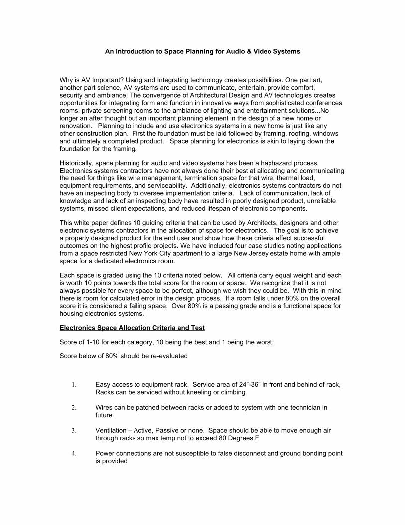
An Introduction to Space Planning for Audio & Video Systems
Why is AV Important? Using and Integrating technology creates possibilities. One part art, another part science, AV systems are used to communicate, entertain, provide comfort, security and ambiance. The convergence of Architectural Design and AV technologies creates opportunities for integrating form and function in innovative ways from sophisticated conferences rooms, private screening rooms to the ambiance of lighting and entertainment solutions...No longer an after thought but an important planning element in the design of a new home or renovation. Planning to include and use electronics systems in a new home is just like any other construction plan. First the foundation must be laid followed by framing, roofing, windows and ultimately a completed product. Space planning for electronics is akin to laying down the foundation for the framing.
Historically, space planning for audio and video systems has been a haphazard process. Electronics systems contractors have not always done their best at allocating and communicating the need for things like wire management, termination space for that wire, thermal load, equipment requirements, and serviceability. Additionally, electronics systems contractors do not have an inspecting body to oversee implementation criteria. Lack of communication, lack of knowledge and lack of an inspecting body have resulted in poorly designed product, unreliable systems, missed client expectations, and reduced lifespan of electronic components.
This white paper defines 10 guiding criteria that can be used by Architects, designers and other electronic systems contractors in the allocation of space for electronics. The goal is to achieve a properly designed product for the end user and show how these criteria effect successful outcomes on the highest profile projects. We have included four case studies noting applications from a space restricted New York City apartment to a large New Jersey estate home with ample space for a dedicated electronics room.
Each space is graded using the 10 criteria noted below. All criteria carry equal weight and each is worth 10 points towards the total score for the room or space. We recognize that it is not always possible for every space to be perfect, although we wish they could be. With this in mind there is room for calculated error in the design process. If a room falls under 80% on the overall score it is considered a failing space. Over 80% is a passing grade and is a functional space for housing electronics systems.
Electronics Space Allocation Criteria and Test
Score of 1-10 for each category, 10 being the best and 1 being the worst.
Score below of 80% should be re-evaluated
1. Easy access to equipment rack. Service area of 24”-36” in front and behind of rack, Racks can be serviced without kneeling or climbing
2. Wires can be patched between racks or added to system with one technician in
future
3. Ventilation – Active, Passive or none. Space should be able to move enough air through racks so max temp not to exceed 80 Degrees F
4. Power connections are not susceptible to false disconnect and ground bonding point
is provided
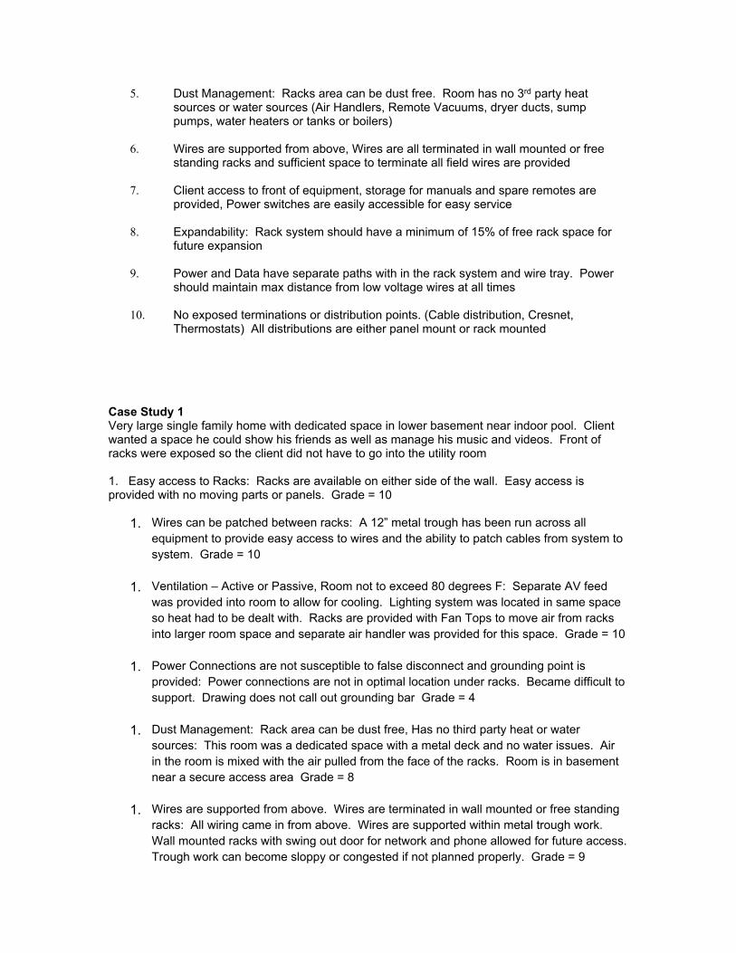
5. Dust Management: Racks area can be dust free. Room has no 3rd party heat sources or water sources (Air Handlers, Remote Vacuums, dryer ducts, sump pumps, water heaters or tanks or boilers)
6. Wires are supported from above, Wires are all terminated in wall mounted or free
standing racks and sufficient space to terminate all field wires are provided
7. Client access to front of equipment, storage for manuals and spare remotes are provided, Power switches are easily accessible for easy service
8. Expandability: Rack system should have a minimum of 15% of free rack space for
future expansion
9. Power and Data have separate paths with in the rack system and wire tray. Power should maintain max distance from low voltage wires at all times
10. No exposed terminations or distribution points. (Cable distribution, Cresnet,
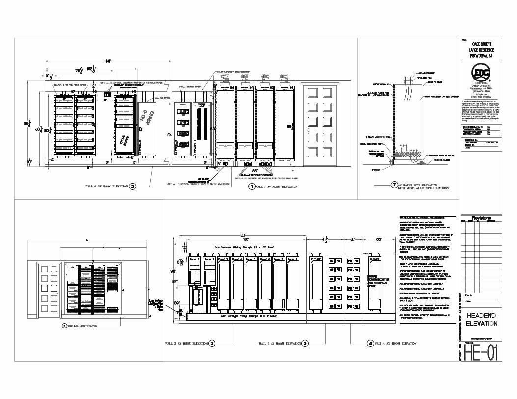
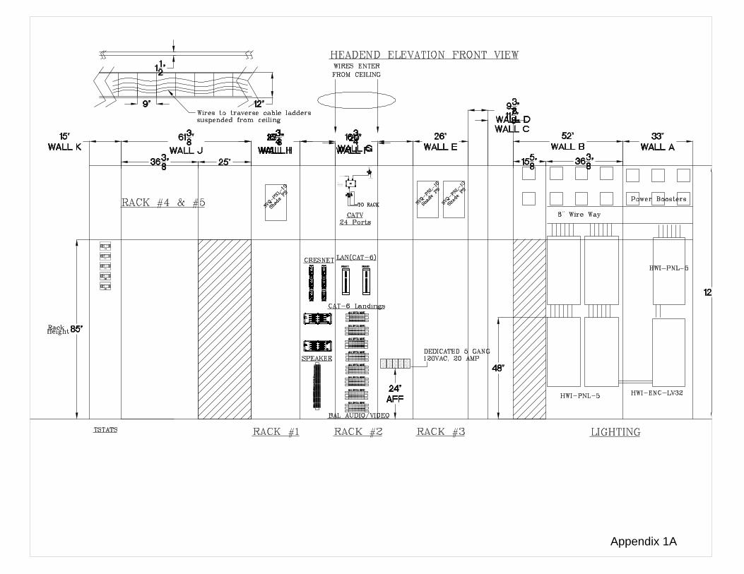
Thermostats) All distributions are either panel mount or rack mounted Case Study 1Very large single family home with dedicated space in lower basement near indoor pool. Client wanted a space he could show his friends as well as manage his music and videos. Front of racks were exposed so the client did not have to go into the utility room 1. Easy access to Racks: Racks are available on either side of the wall. Easy access is provided with no moving parts or panels. Grade = 10
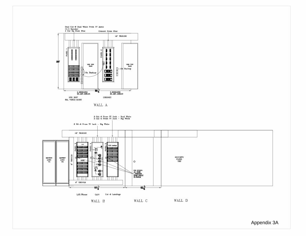
1. Wires can be patched between racks: A 12” metal trough has been run across all equipment to provide easy access to wires and the ability to patch cables from system to system. Grade = 10
1. Ventilation – Active or Passive, Room not to exceed 80 degrees F: Separate AV feed
was provided into room to allow for cooling. Lighting system was located in same space so heat had to be dealt with. Racks are provided with Fan Tops to move air from racks into larger room space and separate air handler was provided for this space. Grade = 10
1. Power Connections are not susceptible to false disconnect and grounding point is
provided: Power connections are not in optimal location under racks. Became difficult to support. Drawing does not call out grounding bar Grade = 4
1. Dust Management: Rack area can be dust free, Has no third party heat or water
sources: This room was a dedicated space with a metal deck and no water issues. Air in the room is mixed with the air pulled from the face of the racks. Room is in basement near a secure access area Grade = 8
1. Wires are supported from above. Wires are terminated in wall mounted or free standing
racks: All wiring came in from above. Wires are supported within metal trough work. Wall mounted racks with swing out door for network and phone allowed for future access. Trough work can become sloppy or congested if not planned properly. Grade = 9
1. Client Access to front of equipment, storage for manuals and spare remotes, Power
switches are provided for easy service: Power switches are accessible from front of rack. Ample storage has been provided for storage of manuals and remotes. Grade = 10
1. Expandability: Systems were provided with ample growth for AV systems. Advanced
wiring rack will support future growth as well. Grade = 10
1. Power and Data have separate paths with in the rack. Power should maintain max distance from low voltage wires: Power had separate paths, power entered racks from the bottom. Low Voltage cables come in from above. Grade = 8
1. No Exposed Terminations or distribution points: This was a high end spaces and
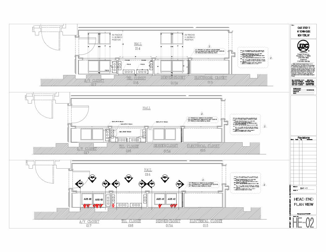
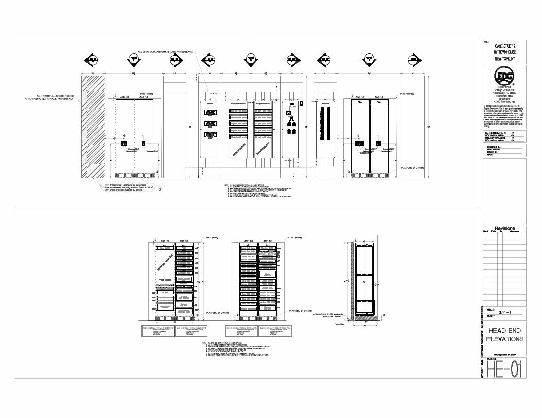
everything had a place and nothing was exposed Grade = 10 Total Grade = 89 Case Study 2Large New York City Town House. Space provided was difficult. A large amount of time went into developing this space. Client wanted to open the doors and have the system shine. All panels and conduits were painted gloss black. All finish grade plywood was used. Enclosures were fitted with plexi glass covers so that all wires could be viewed. 1. Easy access to Racks: Racks are available via pull out rack system. Racks pull out into hallway that is blocked while racks are in service position. Racks are easy to access after they are in service position. Grade = 8 2 Wires can be patched between racks: A 10” metal trough has been run across all equipment to provide easy access to wires and the ability to patch cables from system to system. Racks must be pulled to service position to manage wires Grade = 8 3 Ventilation – Active or Passive, Room not to exceed 80 degrees F: Air from hallway was forced into rack area first. Specific Thermostat was installed into closet. Grade = 10 4 Power Connections are not susceptible to false disconnect and grounding point is provided: Power connections are located in optimal location for pull out racks. Drawing does not call out grounding bar Grade = 6 5 Dust Management: Rack area can be dust free, Has no third party heat or water sources: This closet was a dedicated space Air in the room is mixed with the air pulled from the face of the racks. Room is in basement near a secure access area Grade = 8 6 Wires are supported from above. Wires are terminated in wall mounted or free standing racks: All wiring came in from above. Wires are supported within metal trough work. Pull out racks allow for access to all services. Trough work can become sloppy or congested if not planned properly. Grade = 9 7 Client Access to front of equipment, storage for manuals and spare remotes, Power switches are provided for easy service: Power switches are accessible from front of rack. Ample storage has been provided for storage of manuals and remotes. Grade = 10 8 Expandability: Systems were provided with ample growth for AV systems. Advanced wiring rack will support future growth as well. Grade = 10
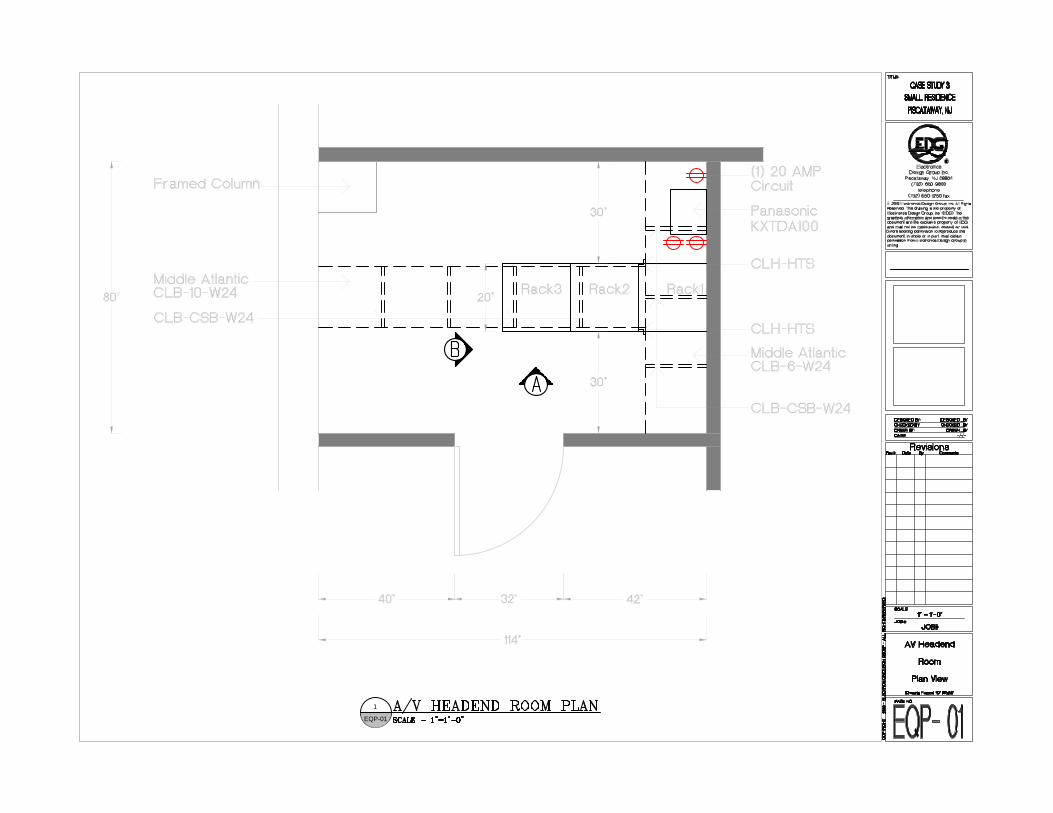
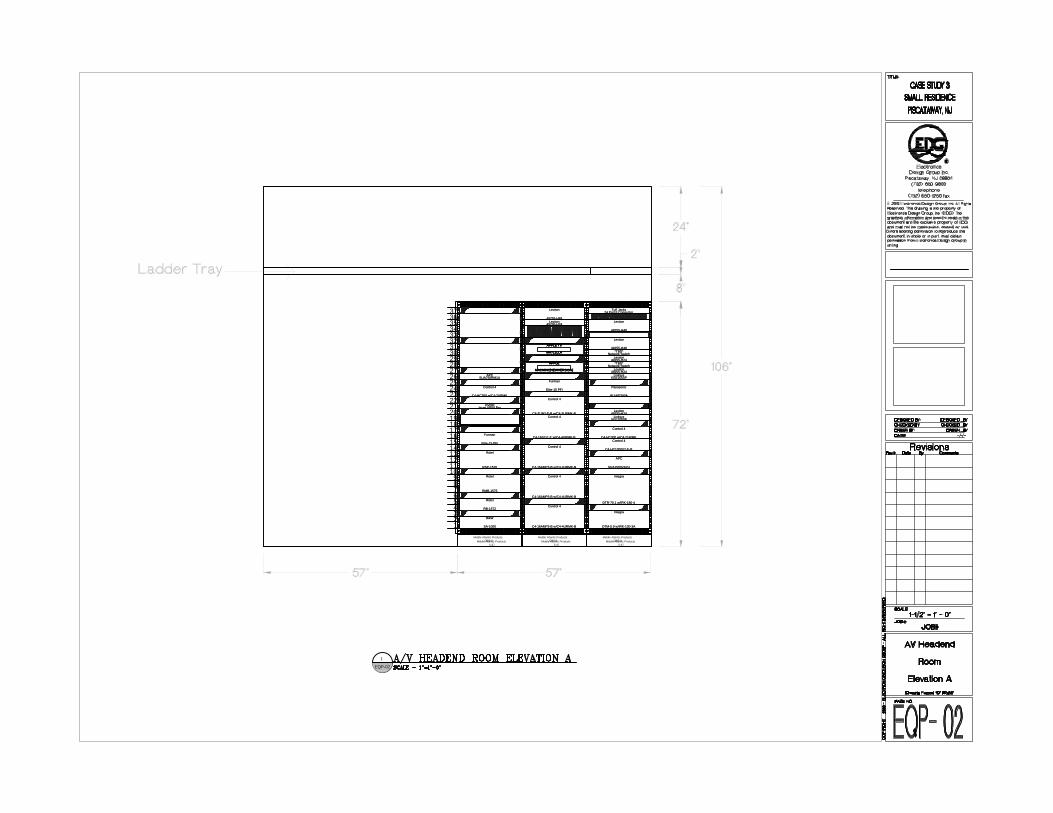
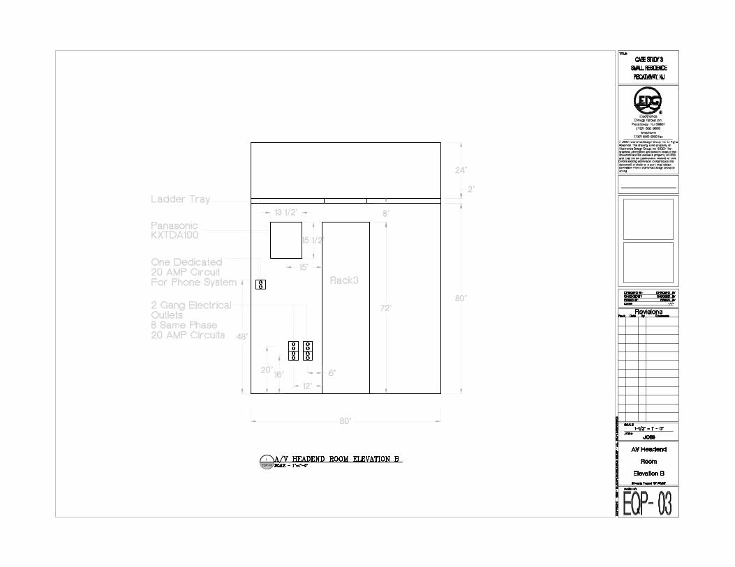
9 Power and Data have separate paths with in the rack. Power should maintain max distance from low voltage wires: Power had separate paths, power entered racks along one side. Low Voltage cables were routed on opposite side. Grade = 8 10 No Exposed Terminations or distribution points: This was a high end spaces and everything had a place and nothing was exposed Grade = 10 Total Grade = 87 Case Study 3Medium sized project in residential single family home. A dedicated space was provided for the best use of the space. This space is nearly perfect. 1. Easy access to Racks: Racks are fixed in the middle of the room. Racks are easy to access. Grade = 10 2 Wires can be patched between racks: A 24” wide metal cable tray has been run across all equipment to provide easy access to wires and the ability to patch cables from system to system. Grade = 10 3 Ventilation – Active or Passive, Room not to exceed 80 degrees F: Air from adjacent HVAC zone was used to cool the room. Grade = 10 4 Power Connections are not susceptible to false disconnect and grounding point is provided: Power connections were located for shortest distance but may still be susceptible to false disconnect. Drawing does not call out grounding bar Grade = 6 5 Dust Management: Rack area can be dust free, Has no third party heat or water sources: This room was a dedicated space Air in the room is mixed with the air pulled from adjacent zone. Room is in basement near a secure access area Grade = 8 6 Wires are supported from above. Wires are terminated in wall mounted or free standing racks: All wiring came in from above. Wires are supported by metal cable tray. Cable Tray must be kept neat, work can become sloppy or congested if not planned properly. Grade = 9 7 Client Access to front of equipment, storage for manuals and spare remotes, Power switches are provided for easy service: Power switches are accessible from front of rack. Ample storage has been provided for storage of manuals and remotes. Grade = 10 8 Expandability: Systems were provided with ample growth for AV systems. Advanced wiring rack will support future growth as well. Grade = 10 9 Power and Data have separate paths with in the rack. Power should maintain max distance from low voltage wires: Power had separate paths, power entered racks along one side. Low Voltage cables were routed on opposite side. Grade = 8 10 No Exposed Terminations or distribution points: This was a high end spaces and everything had a place and nothing was exposed Grade = 10 Total Grade = 91
É
É
É
É
É
EQP-01
1
Middle Atlantic Products5-37
Middle Atlantic ProductsCBS-5Middle Atlantic Products
5-37
Middle Atlantic ProductsCBS-5
Control 4Control 4
C4-HC1000V2-E-BC4-HC1000V2-E-B
Control 4Control 4
C4-HC300 w/C4-2URMKC4-HC300 w/C4-2URMK
Control 4Control 4
C4-16AMP3-B w/C4-4URMK-BC4-16AMP3-B w/C4-4URMK-B
Control 4Control 4
C4-16AMP3-B w/C4-4URMK-BC4-16AMP3-B w/C4-4URMK-B
Control 4Control 4
C4-16AMP3-B w/C4-4URMK-BC4-16AMP3-B w/C4-4URMK-B
Control 4Control 4
C4-16S2-E-E w/C4-4URMK-BC4-16S2-E-E w/C4-4URMK-B
Control 4Control 4
C4-TUN2-E-B w/C4-3URMK-BC4-TUN2-E-B w/C4-3URMK-B
APCAPC
SUA1500VA2USUA1500VA2U
FurmanFurman
Elite-15 PFiElite-15 PFi
LinksysLinksysSGE2000PSGE2000P
APPLE TVAPPLE TVAPPLE TVAPPLE TVAPPLE TV
MA711LLAMA711LLAMA711LLAMA711LLAMA711LLA
APPLEAPPLEAPPLEAPPLEAPPLE
MACMINI [NEWVERSION]MACMINI [NEWVERSION]MACMINI [NEWVERSION]MACMINI [NEWVERSION]MACMINI [NEWVERSION]
IntegraIntegra
DTM-5.9 w/IRK-130-3ADTM-5.9 w/IRK-130-3A
Middle Atlantic Products5-37
Middle Atlantic ProductsCBS-5
123456789
10111213141516171819202122232425262728293031323334353637
RotelRotel
RMB-1575RMB-1575
RotelRotel
RSP-1570RSP-1570
RotelRotel
RB-1572RB-1572
DVDODVDOIscan VP50 ProIscan VP50 Pro
Control 4Control 4
C4-HC300 w/C4-2URMKC4-HC300 w/C4-2URMK
B&WB&W
SA-1000SA-1000
FurmanFurman
Elite-15 PFiElite-15 PFi
APCAPCSUA750RM1USUA750RM1U
IntegraIntegra
DTR-70.1 w/IRK-180-4DTR-70.1 w/IRK-180-4
LevitonLeviton
49255-H4849255-H48
LevitonLeviton49255-H2449255-H24
Tuff JacksTuff Jacks24 Port F Connector24 Port F Connector
LevitonLeviton49255-H2449255-H24
LevitonLeviton49255-H2449255-H24
LinksysLinksysSGE2000PSGE2000P
LevitonLeviton
49255-H4849255-H48
LevitonLeviton
49255-H4849255-H48
LevitonLeviton49255-H2449255-H24
*TBD**TBD*Network SwitchNetwork Switch
*TBD**TBD*Network SwitchNetwork Switch
PanasonicPanasonic
WJ-ND300AWJ-ND300A
É
EQP-02
1
É
EQP-03
1
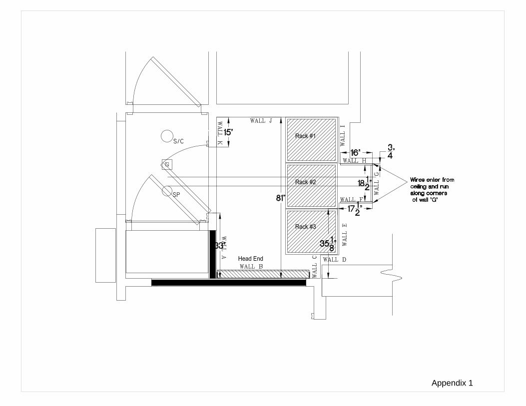
Appendix 1
80 927043
80 927043
80 927043
80 927043
80 927043
From CATV Feed
From Power Supply
To Cable Modem
-3.5dB
+15dB
-7dB
-3.5dB
-7dB -7dB
NOTE:
RG-6 per 100' -4dBRG-59 per 100' -5dB
8dB < At TV < 15dB
-7dB
Appendix 1A
Appendix 2
Appendix 2A
Appendix 3
Appendix 3A
Appendix 4
Appendix 4A
A
Appendix 5
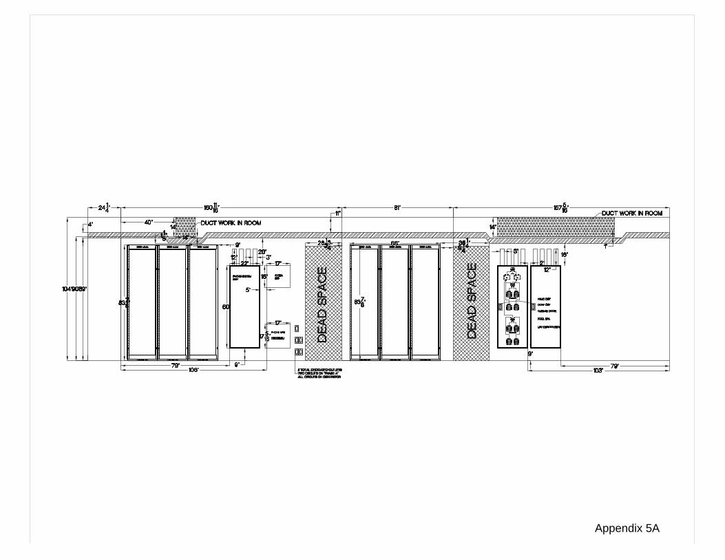
Appendix 5A