Embed Size (px)
Citation preview

Edited by Richard W. Orloff, 01/2001/Page 1
NATIONAL AERONAUTICS AND SPACE ADMINISTRATION
SPACE SHUTTLE MISSION STS-29
PRESS KIT MARCH 1989
TRACKING AND DATA RELAY SATELLITE (TDRS D)
Edited by Richard W. Orloff, 01/2001/Page 2
STS-29 INSIGNIA S88-40316 – The STS-29 insignia was designed to capture and represent the energy and dynamic nature of this nation's space program as America continues to look to the future. The folded ribbon border, the first of its kind in the Shuttle insignia series, gives a sense of three-dimensional depth. The stylistic orbital maneuvering system (OMS) burn symbolizes the powerful forward momentum of the shuttle and a continuing determination to explore the frontiers of space. The colors of the U.S. flag are represented in the insignia's basic red, white, and blue background. In the border, the seven stars between the STS-29 crew names are a tribute to the crew of Challenger. The NASA insignia design for space shuttle flights is reserved for use by the astronauts and for other official use as the NASA Administrator may authorize. Public availability has been approved only in the form of illustrations by the various news media. When and if there is any change in this policy, which we do not anticipate, it will be publicly announced. PHOTO CREDIT: NASA or National Aeronautics and Space Administration.
Edited by Richard W. Orloff, 01/2001/Page 3
RELEASE: 89-23 March, 1989
PUBLIC AFFAIRS CONTACTS
Sarah Keegan/Barbara Selby Office of Space Flight
NASA Headquarters, Washington, DC (Phone: 202/453-2352)
Geoffrey Vincent
Office of Space Operations NASA Headquarters, Washington, DC
(Phone: 202/453-8400)
Lisa Malone Kennedy Space Center, FL
(Phone: 407/867-2468)
Kyle Herring Johnson Space Center, Houston, TX
(Phone: 703/483-5111)
Jerry Berg Marshall Space Flight Center, Huntsville, AL
(Phone: 205/544-0034)
Nancy Lovato Ames-Dryden Flight Research Center, Edwards, CA
(Phone: 805/258-8381)
Jim Elliott Goddard Space Flight Center, Greenbelt, MD
(Phone: 301/286-6256)

Edited by Richard W. Orloff, 01/2001/Page 4
CONTENTS
GENERAL RELEASE 5 GENERAL INFORMATION 7 QUICK LOOK 8 STS-29 MISSION OBJECTIVES 8 SUMMARY OF MAJOR ACTIVITIES 9 LAUNCH PREPARATION, COUNTDOWN AND LIFTOFF
10
MAJOR COUNTDOWN MILESTONES 11 TRAJECTORY SEQUENCE OF EVENTS 13 ABORT MODES 14 LANDING AND POST-LANDING OPERATIONS 15 TRACKING AND DATA RELAY SATELLITE 16 INERTIAL UPPER STAGE 20 SECONDARY PAYLOADS 22 Space Station Heat Pipe Advanced Radiator Element 22 Chromex 24 Protein Crystal Growth Experiment 25 Student Experiments 26 IMAX 27 AMOS 28 OASIS INSTRUMENTATION 29 STS-29 CARGO CONFIGURATION 31 PAYLOAD AND VEHICLE WEIGHT SUMMARY 32 SPACEFLIGHT TRACKING AND DATA NETWORK 33 MCC REAL TIME DATA SYSTEM 34 CREW BIOGRAPHIES 35 SPACE SHUTTLE PROGRAM MANAGEMENT 38

Edited by Richard W. Orloff, 01/2001/Page 5
RELEASE: 89-23 March, 1989
THIRD TRACKING AND DATA RELAY SATELLITE TO BE DEPLOYED BY STS-29
Deployment of the third Tracking and Data Relay Satellite (TDRS-D) will highlight the 28th Space Shuttle mission (STS-29). The assessed launch date is no earlier than March 10, 1989. Three TDRS, operating from geosynchronous orbit, are required to complete the constellation known as the Tracking and Data Relay Satellite System (TDRSS). TDRSS will increase communications, between Earth-orbiting spacecraft and a ground-based tracking station, from 15 to 85 percent per orbit and facilitate a much higher rate of data flow. TDRS-C was successfully deployed on STS-26 in September 1988 and is located in geosynchronous orbit at 171 degrees W. longitude, south of Hawaii. TDRS-D will be located at 41 degrees W. longitude, east of Brazil. TDRS-A, deployed on STS-6 in April 1983, then will be moved to a parking orbit and used only if a failure occurs with one of the remaining two satellites. TDRS-B was lost in the 51-L Challenger accident. Commander of the five-man crew is Michael L. Coats, captain, USN. Coats was pilot of STS 41-D, the maiden flight of orbiter Discovery. John E. Blaha, colonel, USAF, is pilot of the mission. STS-29 will be his first space flight. Rounding out the crew are three mission specialists: James F. Buchli, colonel, USMC; Robert C. Springer, colonel, USMC; and James P. Bagian, M.D. Buchli is making his third Shuttle flight having flown as a mission specialist on STS 51-C, the first Department of Defense Shuttle mission, and STS 61-A, the West German Spacelab flight. Springer and Bagian are making their first Shuttle flights. Discovery, making its eighth flight, is assessed to be ready for launch no earlier than 8:11 a.m. EST, March 10, from the Kennedy Space Center, Fla., launch pad 39-B, into a 160 nautical mile, 28.45 degree orbit. Nominal mission duration is 5 days, 1 hour, 7 minutes. Deorbit is planned on orbit 80, with landing scheduled for 9:48 a.m. EST, March 15, at Edwards Air Force Base, Calif. In the event of a slip in the launch, liftoff would occur 1 minute earlier for each day the launch is delayed. TDRS-D will be deployed 6 hours, 13 minutes into the mission on flight day 1. Two additional deployment opportunities are available on that day and one the following day. An Air Force-developed inertial upper stage (IUS) will boost the TDRS to geosynchronous orbit (22,300 miles above Earth) after deployment from the Shuttle. The IUS is mated to the TDRS-D and the combination spacecraft and upper stage will be spring ejected from the payload bay of the orbiter. Following deployment, Discovery will maneuver to a safe position behind and above the TDRS-D/IUS before the first stage of the two-stage IUS motor ignites about an hour after deployment. The three-axis, stabilized upper stage will maneuver TDRS to the desired attitude where it will be configured for operation by the NASA White Sands Ground Terminal, NM. CONTEL, Atlanta, Ga., owns and operates the TDRSS for NASA. TRW's Defense and Space Systems Group, Redondo Beach, Calif., builds the satellites. The Orbiter Experiments Program Autonomous Supporting Instrumentation System (OASIS) will be flown again on STS-29 to record environmental data in the orbiter payload bay during flight phases. OASIS will measure TDRS vibration, strain, acoustics and temperature during launch ascent using transducers affixed directly to the payload. OASIS flight hardware consists of signal conditioning, multiplexing and recording equipment mounted on a Shuttle adaptive payload carrier behind the TDRS. Command and status interface is achieved through the standard mixed cargo harness and the general purpose computers.

Edited by Richard W. Orloff, 01/2001/Page 6
In addition to TDRS-D and OASIS, Discovery will carry the Space Station Heat Pipe Advanced Radiator Element (SHARE) in the payload bay. Several secondary payloads will be carried in the middeck of Discovery, including the IMAX camera, two student experiments, a protein crystal growth experiment and a chromosome and plant cell division experiment. After landing, Discovery will be towed to the NASA Ames-Dryden Flight Research Facility, hoisted atop the Shuttle Carrier Aircraft and ferried back to the Kennedy Space Center to begin processing for its next flight scheduled for August.
(END OF GENERAL RELEASE; BACKGROUND INFORMATION FOLLOWS.)
Edited by Richard W. Orloff, 01/2001/Page 7
GENERAL INFORMATION NASA Select Television Transmission The schedule for television transmission from the orbiter and for the change-of-shift briefings from Johnson Space Center, Houston, will be available during the mission at Kennedy Space Center, Fla.; Marshall Space Flight Center, Huntsville, AL; Johnson Space Center; and NASA Headquarters, Washington, D.C. The television schedule will be updated daily to reflect changes dictated by mission operations. NASA Select television is available on RCA Satcom F-2R, Transponder 13, located at 72 degrees west longitude. Special Note To Broadcasters Beginning in February and continuing throughout the mission, approximately 7 minutes of audio interview material with the crew of STS-29 will be available to broadcasters by calling 202/269-6572. Status Reports Status reports on countdown and mission progress, on-orbit activities and landing operations will be produced by the appropriate NASA newscenter. Briefings An STS-29 mission press briefing schedule will be issued prior to launch. During the mission, flight control personnel will be on 8-hour shifts. Change-of-shift briefings by the off-going flight director will occur at approximately 8-hour intervals.

Edited by Richard W. Orloff, 01/2001/Page 8
STS-29 QUICK LOOK
Assessed Launch Date: March 10, 1989 Launch Window: 8:11 a.m. - 10:41 a.m. EST Launch Site: KSC, Pad 39B Orbiter: Discovery (OV-103) Altitude: 160 nm Inclination: 28.45 degrees Duration: 5 days, 1 hour, 7 minutes Landing Date/Time: March 15, 1989, 9:48 a.m. EST Primary Landing Site: Edwards AFB, Calif., Runway 17 Alternate Landing Sites:
Return to Launch Site - Kennedy Space Center, FL, Runway 33
Transoceanic Abort Landing - Ben Guerir, Morocco Abort Once Around - Edwards AFB, CA Crew: Michael L. Coats, Commander John E. Blaha, Pilot James F. Buchli, Mission Specialist Robert C. Springer, Mission Specialist James P. Bagian, Mission Specialist Primary Payload: Tracking & Data Relay Satellite (TDRS-D) Secondary Payloads: Space Station Heat Pipe Advanced Radiator Element (SHARE) Chromosomes & Plant Cell Division (CHROMEX) Protein Crystal Growth (PCG) Shuttle Student Involvement Program (SSIP) - 2 experiments Orbiter Experiments - Autonomous Supporting Instrumentation System (OASIS) IMAX Camera
STS-29 MISSION OBJECTIVES The primary objective of this flight is to successfully deploy the Tracking and Data Relay Satellite-D/Inertial Upper Stage (TDRS-D/IUS). TDRS-D is scheduled to be deployed on flight day 1, orbit 6. Several backup deployment opportunities exist during the flight. Secondary objectives are to perform all operations necessary to support the requirements of the middeck and payload bay experiments.
Edited by Richard W. Orloff, 01/2001/Page 9
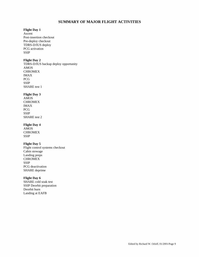
SUMMARY OF MAJOR FLIGHT ACTIVITIES Flight Day 1 Ascent Post-insertion checkout Pre-deploy checkout TDRS-D/IUS deploy PCG activation SSIP Flight Day 2 TDRS-D/IUS backup deploy opportunity AMOS CHROMEX IMAX PCG SSIP SHARE test 1 Flight Day 3 AMOS CHROMEX IMAX PCG SSIP SHARE test 2 Flight Day 4 AMOS CHROMEX SSIP Flight Day 5 Flight control systems checkout Cabin stowage Landing preps CHROMEX SSIP PCG deactivation SHARE deprime Flight Day 6 SHARE cold soak test SSIP Deorbit preparation Deorbit burn Landing at EAFB

Edited by Richard W. Orloff, 01/2001/Page 10
LAUNCH PREPARATIONS, COUNTDOWN AND LIFTOFF After the successful STS-26 mission, Discovery was returned to KSC from Dryden Flight Research Facility on Oct. 8. The next day, Discovery was towed to the processing hangar for post-flight deconfiguration and inspections. As planned, the three main engines were removed in October and taken to the main engine shop in the Vehicle Assembly Building for the replacement of several components. During post-flight inspections, technicians discovered a small leak in the cooling system of the main combustion chamber of the number one main engine. That engine was shipped back to the vendor where repairs could be made and a new engine was shipped from the Stennis Space Center, Miss. Discovery's three main engines were installed before the end of last year. Engine 2031 is installed in the number one position, engine 2022 is in the number two position and engine 2028 is in the number three position. The right hand orbital maneuvering system pod was removed in late October and transferred to the Hypergolic Maintenance Facility where a small internal leak was repaired. One of the orbiter's cooling systems, called the flash evaporator system, was replaced after some in-flight problems. Post-flight inspections revealed that the system was clogged with foreign material. Once the turn-around activities were completed, Discovery was transferred from the Orbiter Processing Facility to the Vehicle Assembly Building on Jan. 19. Solid rocket motor (SRM) segments began arriving at KSC in September, and the first segment - the left aft booster - was stacked on Mobile Launcher 2 in VAB high bay 1 on Oct. 21. Booster stacking operations were completed by early December and the external tank was mated to the two boosters on Dec. 16. The OASIS payload was installed in Discovery's payload bay for flight on Dec. 9. Flight crew members came to KSC to perform the Crew Equipment Interface Test on Dec. 11 to become familiar with Discovery's crew compartment and equipment associated with the mission. The Tracking and Data Relay Satellite (TDRS-D) arrived at the Vertical Processing Facility (VPF) on Nov. 30, and its Inertial Upper Stage (IUS) arrived Dec. 27. The TDRS/IUS were joined together on Dec. 29 and all integrated testing was performed the first week of January. As part of those tests, Astronauts James Bagian and Robert Springer participated in the mission sequence test to verify payload functions that occur post-launch and during deployment. A variety of middeck payloads and experiments, some of which are time critical and installed during the launch countdown, are processed through various KSC facilities. Discovery was moved from the OPF to the VAB on Jan. 23, where it was mated to the external tank and SRBs. A Shuttle Interface Test was conducted to check the mechanical and electrical connections between the various elements of the Shuttle vehicle and onboard flight systems. The assembled Space Shuttle vehicle was rolled out of the VAB aboard its mobile launcher platform for the 4.2 mile trip to Launch Pad 39-B on Feb. 3. TDRS-D and its IUS upper stage were transferred from the VPF to Launch Pad 39-B on Jan. 17. The payload was installed into Discovery's payload bay on Feb. 6. A countdown demonstration test, a dress rehearsal for the STS-29 flight crew and KSC launch team and a practice countdown for the launch, was completed on Feb. 7. Launch preparations scheduled the last 2 weeks prior to launch countdown include change-out of the orbiter SSME liquid oxygen pumps; final vehicle ordnance activities, such as power-on, stray-voltage checks and resistance checks of firing circuits; loading the fuel cell storage tanks; pressurizing the hypergolic propellant tanks aboard the vehicle; final payload closeouts; and a final functional check of the range safety and SRB ignition, safe and arm devices.

Edited by Richard W. Orloff, 01/2001/Page 11
The launch countdown is scheduled to pick up at the T-minus-43-hour mark, leading up to the first Shuttle liftoff for the year. The STS-29 launch will be conducted by a joint NASA/industry team from Firing Room 1 in the Launch Control Center.

Edited by Richard W. Orloff, 01/2001/Page 12
MAJOR COUNTDOWN MILESTONES T-43 Hours Power up the Space Shuttle vehicle. T-34 Hours Begin orbiter and ground support equipment closeouts for launch. T-30 Hours Activate orbiter's navigation aids. T-27 Hours (holding) Enter first built-in hold for 8 hrs. T-27 Hours (counting) Begin preparations for loading fuel cell storage tanks with liquid oxygen and
liquid hydrogen T-25 Hours Load fuel cell liquid oxygen T-22 Hours, 30 Min Load fuel cell liquid hydrogen. T-22 Hours Perform interface check between Mission Control and Merritt Island Launch
Area (MILA) tracking station. T-20 Hours Activate and warm up inertial measurement units (IMUs). T-19 Hours Enter the 8-hour, built-in hold. Activate orbiter comm system. T-11 Hours (holding) Start 18-hour, 10-minute, built-in hold. Check ascent switch list on orbiter flight
and middecks. T-11 Hours (counting) Retract Rotating Service Structure. T-9 Hours Activate orbiter's fuel cells. T-8 Hours Configure Mission Control communications for launch. Start clearing blast danger area. T-6 Hours, 30 Min Perform Eastern Test Range open loop command test. T-6 Hours Enter 1-hour built-in hold. T-6 Hours (counting) Start external tank chilldown and propellant loading. T-5 Hours Start IMU pre-flight calibration. T-4 Hours Perform MILA antenna alignment. T-3 Hours Begin 2-hour built-in hold. Loading external tank completed and tank in stable
replenishment mode. Ice team to pad for inspections. Closeout crew to white room to begin prepping orbiter's cabin for flight crew entry. Wake flight crew (launch minus 4 hours, 55 minutes).
T-3 Hours (counting) Resume countdown.

Edited by Richard W. Orloff, 01/2001/Page 13
MAJOR COUNTDOWN MILESTONES T-2 Hours, 55 Min Flight crew departs O&C Building for 39-B (Launch minus 3 hours, 15
minutes). T-2 Hours, 30 Min Crew enters orbiter vehicle (Launch minus 2 Hours, 50 minutes). T-60 Min Start pre-flight alignment of IMUs. T-20 Min (holding) 10-minute, built-in hold begins. T-20 Min (counting) Configure orbiter computers for launch. T-10 Min White room closeout crew cleared through area roadblocks. T-9 Min (holding) 10-minute, built-in hold begins. Perform status check and receive Mission
Management Team "go." T-9 Min (counting) Start ground launch sequencer. T-7 Min, 30 Sec Retract orbiter access arm. T-5 Min Start auxiliary power units. Arm range safety, SRB ignition systems. T-3 Min, 30 Sec Orbiter goes on internal power. T-2 Min, 55 Sec Pressurize liquid oxygen tank and retract gaseous oxygen vent hood. T-1 Min, 57 Sec Pressurize liquid hydrogen tank. T-31 Sec "Go" from ground computer for orbiter computers to start the automatic launch
sequence. T-28 Sec Start SRB hydraulic power units. T-21 Sec Start SRB gimbal profile test. T-6.6 Sec Main engine start. T-3 Sec Main engines at 90 percent thrust. T-0 SRB ignition, holddown-post release and liftoff. T+7 Sec Shuttle clears launch tower and control switches to Houston.
Edited by Richard W. Orloff, 01/2001/Page 14
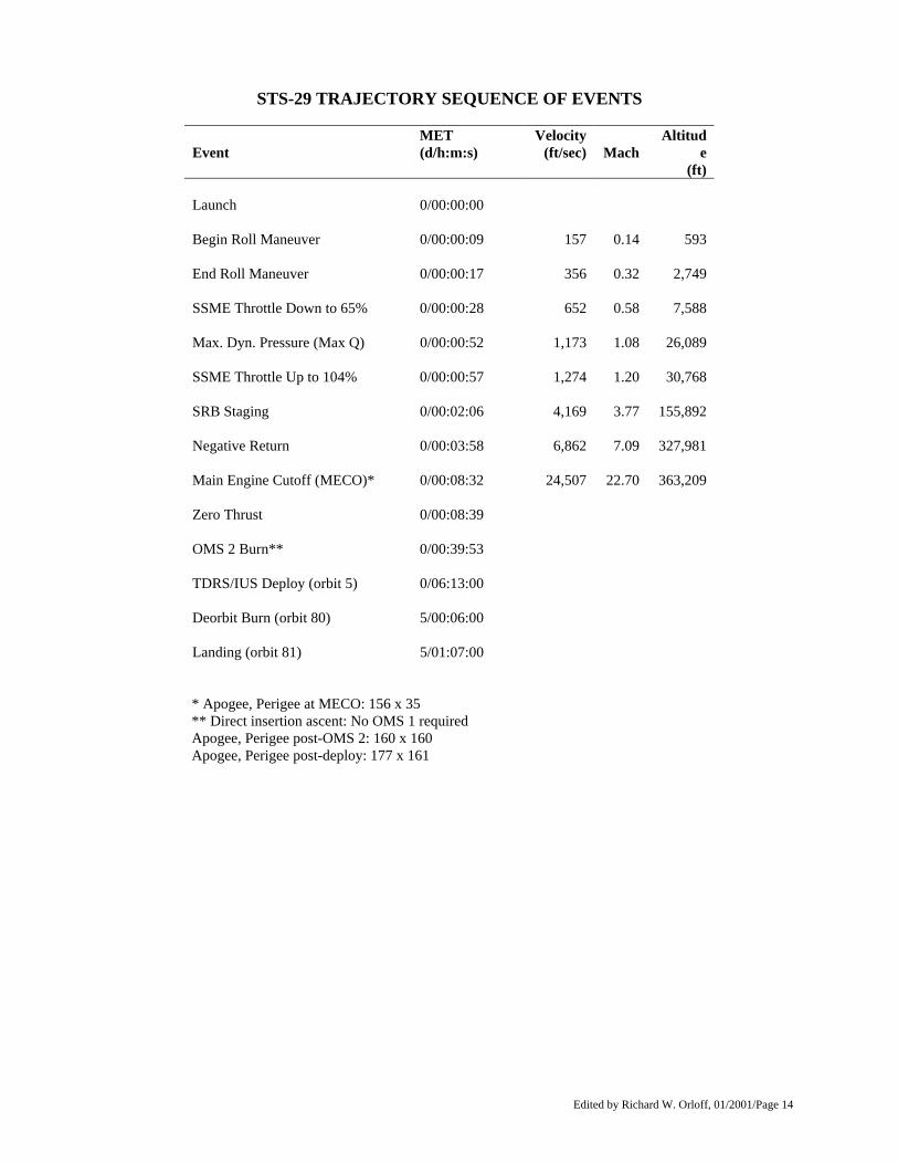
STS-29 TRAJECTORY SEQUENCE OF EVENTS
Event
MET (d/h:m:s)
Velocity (ft/sec)
Mach
Altitude
(ft) Launch 0/00:00:00 Begin Roll Maneuver 0/00:00:09 157 0.14 593 End Roll Maneuver 0/00:00:17 356 0.32 2,749 SSME Throttle Down to 65% 0/00:00:28 652 0.58 7,588 Max. Dyn. Pressure (Max Q) 0/00:00:52 1,173 1.08 26,089 SSME Throttle Up to 104% 0/00:00:57 1,274 1.20 30,768 SRB Staging 0/00:02:06 4,169 3.77 155,892 Negative Return 0/00:03:58 6,862 7.09 327,981 Main Engine Cutoff (MECO)* 0/00:08:32 24,507 22.70 363,209 Zero Thrust 0/00:08:39 OMS 2 Burn** 0/00:39:53 TDRS/IUS Deploy (orbit 5) 0/06:13:00 Deorbit Burn (orbit 80) 5/00:06:00 Landing (orbit 81) 5/01:07:00
* Apogee, Perigee at MECO: 156 x 35 ** Direct insertion ascent: No OMS 1 required Apogee, Perigee post-OMS 2: 160 x 160 Apogee, Perigee post-deploy: 177 x 161
Edited by Richard W. Orloff, 01/2001/Page 15
SPACE SHUTTLE ABORT MODES Space Shuttle launch abort philosophy aims toward safe and intact recovery of flight crew, orbiter and payload. Modes are:
• Abort-To-Orbit (ATO) -- Partial loss of main engine thrust late enough to permit reaching a minimal 105-nm orbit with orbital maneuvering system engines.
• Abort-Once-Around (AOA) -- Earlier main engine shutdown with the capability to allow one orbit around
before landing at Edwards AFB, Calif.; White Sands Space Harbor (Northrup Strip), N.M.; or the Shuttle Landing Facility (SLF) at KSC, Fla.
• Trans-Atlantic Abort Landing (TAL) -- Loss of two main engines midway through powered flight would
force a landing at Ben Guerir, Morocco; Moron, Spain; or Banjul, The Gambia.
• Return-To-Launch-Site (RTLS) -- Early shutdown of one or more engines and without enough energy to reach Ben Guerir, would result in a pitch around and thrust back toward KSC until within gliding distance of the SLF.
STS-29 contingency landing sites are Edwards AFB, White Sands, Kennedy Space Center, Ben Guerir, Moron and Banjul.

Edited by Richard W. Orloff, 01/2001/Page 16
LANDING AND POST-LANDING ACTIVITIES KSC is responsible for ground operations of the orbiter once it has rolled to a stop on the runway at Edwards AFB. Operations include preparing the Shuttle for the return trip to Kennedy. After landing, the flight crew aboard Discovery begins "safing" vehicle systems. Immediately after wheelstop, specially garbed technicians will first determine that any residual hazardous vapors are below significant levels for other safing operations to proceed. A mobile white room is moved into place around the crew hatch once it is verified that there are no concentrations of toxic gases around the forward part of the vehicle. The crew is expected to leave Discovery about 45 to 50 minutes after landing. As the crew exits, technicians enter the orbiter to complete the vehicle safing activity. Once the initial aft safety assessment is made, access vehicles are positioned around the rear of the orbiter so that lines from the ground purge and cooling vehicles can be connected to the umbilical panels on the aft end of Discovery. Freon line connections are completed and coolant begins circulating through the umbilicals to aid in heat rejection and protect the orbiter's electronic equipment. Other lines provide cooled, humidified air to the payload bay and other cavities to remove any residual fumes and provide a safe environment inside Discovery. A tractor will be connected to Discovery and the vehicle will be towed off the runway at Edwards and positioned inside the Mate/Demate Device at the nearby Ames-Dryden Flight Research Facility. After the Shuttle has been jacked and leveled, residual fuel cell cryogenics are drained and unused pyrotechnic devices are disconnected. The aerodynamic tail cone is installed over the three main engines, and the orbiter is bolted on top of the 747 Shuttle Carrier Aircraft for the ferry flight back to Florida. A refueling stop is necessary to complete the journey. Once back at Kennedy, Discovery will be pulled inside the hangar-like facility for post-flight inspections and in-flight anomaly troubleshooting. These operations are conducted in parallel with the start of routine systems reverification to prepare Discovery for its next mission.

Edited by Richard W. Orloff, 01/2001/Page 17
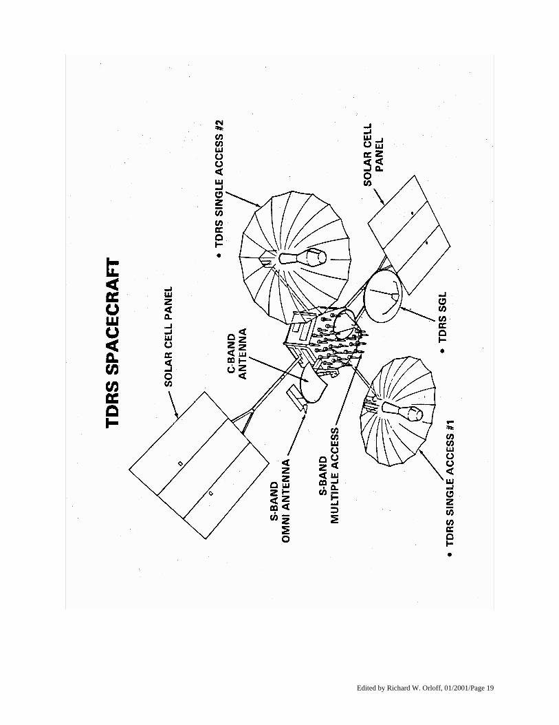
TRACKING AND DATA RELAY SATELLITE SYSTEM The Tracking and Data Relay Satellite, TDRS-D, is the fourth TDRS communications spacecraft to be launched aboard the Space Shuttle and completes the constellation of on-orbit satellites for NASA's advanced space communications system. TDRS-1 was launched during Challenger's maiden flight in April 1983. The second was lost during the Challenger accident in January 1986. TDRS-3 was launched successfully on Sept. 29, 1988, during the landmark mission of Discovery, which returned the Space Shuttle to flight. TDRS-1 is in geosynchronous orbit over the Atlantic Ocean, just east of Brazil (41 degrees west longitude at the equator). When it was launched, it failed to reach its desired orbit because of a failure in the upper-stage booster rocket. A NASA- industry team subsequently conducted a series of delicate spacecraft maneuvers, using on-board thrusters, to place TDRS-1 into the desired 22,300-mile-altitude orbit. TDRS-3 is in geosynchronous orbit over the Pacific Ocean, south of Hawaii (171 degree west longitude, also over the equator). It has performed flawlessly in tests and helped support the STS-27 mission in December 1988. After its launch, TDRS-D will be designated TDRS-4. Following its arrival at geosynchronous orbit and a series of tests, it will replace the partially degraded TDRS-1 over the Atlantic. TDRS-1 then will be moved to 79 degrees west longitude, above the Equator, where it will be used as an on- orbit spare. The two operational TDRS -- those located at 41 and 171 degrees west longitude -- will support up to 23 user spacecraft simultaneously and provide two basic types of service: a multiple-access service that simultaneously relays data from as many as 19 low-data-rate user spacecraft; and a single-access service that provides two high-data-rate communications relays from each satellite. TDRS-4 will be deployed from the orbiter about 6 hours after launch. The solid-propellant Boeing/U.S. Air Force Inertial Upper Stage (IUS) will transfer the satellite to geosynchronous orbit. IUS separation will occur about 13 hours after launch. The concept of using advanced communications satellites was developed in the early 1970s, following studies showing that a system of communications satellites operated from a single ground terminal could support Space Shuttle and other low-Earth-orbit space missions more effectively than a worldwide network of ground stations. The current ground station network can only provide support for a small fraction -- typically 15 to 20 percent -- of the orbits of user spacecraft. The modern, space- based TDRS network covers at least 85 percent of the orbits. The new system also will facilitate a much higher information flow rate between the spacecraft and the ground. This will be particularly important as NASA resumes regular Shuttle flights and launches satellites with high data rates. NASA's Space Tracking and Data Network ground stations, managed by the Goddard Space Flight Center, Greenbelt, Md., will be reduced significantly in number. Three of the network's present ground stations -- Madrid, Spain; Canberra, Australia; and Goldstone, Calif. -- already have been transferred to the Deep Space Network, managed by the Jet Propulsion Laboratory, Pasadena, Calif. The remaining ground stations, except those needed for launch operations, will be closed or transferred to other agencies. The White Sands Ground Terminal (WSGT) is situated on a NASA test site located between Las Cruces and White Sands, N.M. A collocated NASA facility provides the interface between the WSGT and the NASA space network facilities at Goddard Space Flight Center. A technologically advanced second ground terminal is being built near White Sands to provide back-up and additional capability. The tracking and data relay satellites are the largest privately owned telecommunications spacecraft ever built, and the first to handle satellite communications through the S and Ku frequency bands. Each weighs about 2 tons, spans almost 60 feet across its solar panels and contains seven antennas. Each of the two gold-plated, single-access antennas measures 16 feet in diameter and, when fully deployed, spans more than 42 feet from tip to tip. The combination of satellites and ground facilities is referred to as the Tracking and Data Relay Satellite System or TDRSS. NASA leases the TDRSS complement of services from CONTEL, Atlanta, Ga., which is the owner,

Edited by Richard W. Orloff, 01/2001/Page 18
operator and prime contractor. CONTEL's two primary subcontractors are TRW's Space and Technology Group, Redondo Beach, Calif., and the Harris Corporation's Government Communications Systems Division, Melbourne, Fla. TRW designed and built the spacecraft and software for ground terminal operation, and integrated and tested the system. Harris designed and built the ground terminal equipment. The Space Shuttle, LANDSAT Earth Resources satellites, Solar Mesosphere Explorer, Earth Radiation Budget Satellite, Solar Maximum Mission satellite and Spacelab have been primary users of TDRSS. They will be joined in the future by the Hubble Space Telescope, Gamma Ray Observatory, Upper Atmosphere Research Satellite and others.
Edited by Richard W. Orloff, 01/2001/Page 19

Edited by Richard W. Orloff, 01/2001/Page 20

Edited by Richard W. Orloff, 01/2001/Page 21
INERTIAL UPPER STAGE The Inertial Upper Stage (IUS) will be used to place NASA's TDRS-D into geosynchronous orbit during the STS-29 Space Shuttle mission. The STS-29 crew will deploy the combined IUS/TDRS-D payload approximately 6 hours, 13 minutes after liftoff, in a low-Earth orbit of 160 nautical miles. Upper stage airborne support equipment, located in the orbiter payload bay, positions the combined IUS/TDRS-D into its proper deployment attitude -- an angle of 52 degrees -- and ejects it into low-Earth orbit. Deployment from the orbiter will be by a spring-ejection system. Following deployment, the orbiter will move away from the IUS/TDRS-D to a safe distance. The IUS first stage will fire about 1 hour after deployment. After the first stage burn of 146 seconds, the solid fuel motor will shut down. After coasting for about 5 hours, 13 minutes, the first stage will separate and the second stage motor will ignite at 6 hours, 12 minutes after deployment to place the spacecraft in its desired orbit. Following a 108-second burn, the second stage will shut down as the IUS/TDRS-D reaches the predetermined, geosynchronous orbital position. Thirteen hours, 9 minutes after liftoff, the second stage will separate from TDRS-D and perform an anti-collision maneuver with its onboard reaction control system. The IUS has a number of features which distinguish it from previous upper stages. It has the first completely redundant avionics system developed for an unmanned space vehicle. It can correct in-flight features within milliseconds. Other advanced features include a carbon composite nozzle throat that makes possible the high-temperature, long-duration firing of the IUS motors and a redundant computer system. The IUS is 17 ft. long, 9 ft. in diameter and weighs more than 32,500 lb., including 27,400 lb. of solid fuel propellant. The IUS consists of an aft skirt, an aft stage containing 21,400 lb. of solid propellant which generates approximately 42,000 lb. of thrust, an interstage, a forward stage containing 6,000 lb. of propellant generating 18,000 lb. of thrust, and an equipment support section. The equipment support section contains the avionics which provide guidance, navigation, telemetry, command and data management, reaction control and electrical power. The IUS is built by Boeing Aerospace, Seattle, under contract to the U.S. Air Force Systems Command. Marshall Space Flight Center, Huntsville, Ala., is NASA's lead center for IUS development and program management of NASA-configured IUSs procured from the Air Force.

Edited by Richard W. Orloff, 01/2001/Page 22
Edited by Richard W. Orloff, 01/2001/Page 23
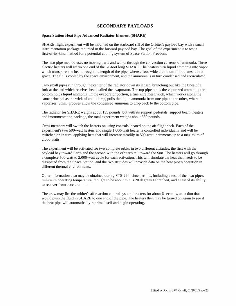
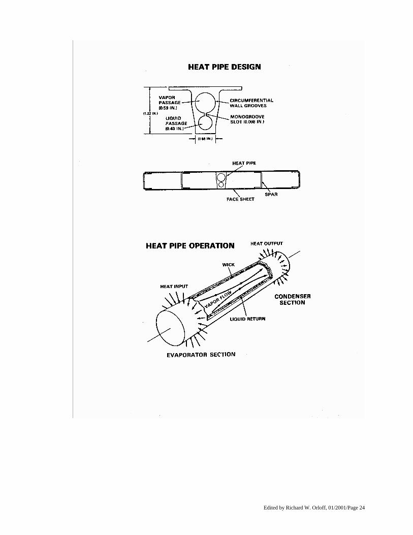
SECONDARY PAYLOADS Space Station Heat Pipe Advanced Radiator Element (SHARE) SHARE flight experiment will be mounted on the starboard sill of the Orbiter's payload bay with a small instrumentation package mounted in the forward payload bay. The goal of the experiment is to test a first-of-its-kind method for a potential cooling system of Space Station Freedom. The heat pipe method uses no moving parts and works through the convection currents of ammonia. Three electric heaters will warm one end of the 51-foot long SHARE. The heaters turn liquid ammonia into vapor which transports the heat through the length of the pipe, where a foot-wide aluminum fin radiates it into space. The fin is cooled by the space environment, and the ammonia is in turn condensed and recirculated. Two small pipes run through the center of the radiator down its length, branching out like the tines of a fork at the end which receives heat, called the evaporator. The top pipe holds the vaporized ammonia; the bottom holds liquid ammonia. In the evaporator portion, a fine wire mesh wick, which works along the same principal as the wick of an oil lamp, pulls the liquid ammonia from one pipe to the other, where it vaporizes. Small grooves allow the condensed ammonia to drop back to the bottom pipe. The radiator for SHARE weighs about 135 pounds, but with its support pedestals, support beam, heaters and instrumentation package, the total experiment weighs about 650 pounds. Crew members will switch the heaters on using controls located on the aft flight deck. Each of the experiment's two 500-watt heaters and single 1,000-watt heater is controlled individually and will be switched on in turn, applying heat that will increase steadily in 500-watt increments up to a maximum of 2,000 watts. The experiment will be activated for two complete orbits in two different attitudes, the first with the payload bay toward Earth and the second with the orbiter's tail toward the Sun. The heaters will go through a complete 500-watt to 2,000-watt cycle for each activation. This will simulate the heat that needs to be dissipated from the Space Station, and the two attitudes will provide data on the heat pipe's operation in different thermal environments. Other information also may be obtained during STS-29 if time permits, including a test of the heat pipe's minimum operating temperature, thought to be about minus 20 degrees Fahrenheit, and a test of its ability to recover from acceleration. The crew may fire the orbiter's aft reaction control system thrusters for about 6 seconds, an action that would push the fluid in SHARE to one end of the pipe. The heaters then may be turned on again to see if the heat pipe will automatically reprime itself and begin operating.
Edited by Richard W. Orloff, 01/2001/Page 24
Edited by Richard W. Orloff, 01/2001/Page 25
Chromex This experiment will determine whether the roots of a plant in microgravity will develop similarly to those on Earth. Root- free shoots of the plants daylily and haplopappus will be used. The experiment will determine whether:
• The normal rate, frequency and patterning of cell division in the root tops can be sustained in space.
• The chromosomes and genetic makeup is maintained during and after exposure to space flight
conditions.
• Aseptically grown tissue cultured materials will grow and differentiate normally in space The criteria for comparison include: number of roots formed, length, weight and quality based on subjective appraisal as well as quantitative morphological and histological examination. Root tip cells will be analyzed for their karyotype, the configuration of chromosomes, upon return. Haplopappus dicatolydon is a unique flowering plant with four chromosomes in its diploid cells (2n=4). Daylily monocatolydon also has specific features of its karyotype 2n=22. Daylily and haplopappus gracilis will be flown in the plant growth unit (PGU), located in the orbiter middeck. The PGU can hold up to six plant growth chambers (PGC). One PGC will be replaced with the atmospheric exchange system that will filter cabin air before pumping through the remaining PGCs. The experimental plan is to collect and treat roots post flight, before the first cell division cycle is completed. Previous observations of some plants grown in space have indicated a substantially lowered level of cell division in primary root tips and a range of chromosomal abnormalities, such as breakage and fusion.

Edited by Richard W. Orloff, 01/2001/Page 26
Protein Crystal Growth Experiment STS-29 protein crystal growth experiments are expected to help advance a technology attracting intense interest from major pharmaceutical houses, the biotech industry and agrochemical companies. A team of industry, university and government research investigators will explore the potential advantages of using protein crystals grown in space to determine the complex, three- dimensional structure of specific protein molecules. Knowing the precise structure of these complex molecules provides the key to understanding their biological function and could lead to methods of altering or controlling the function in ways that may result in new drugs. It is through sophisticated analysis of a protein in crystallized form that scientists are able to construct a model of the molecular structure. The problem is that protein crystals grown on Earth are often small and flawed. Protein crystal growth experiments flown on four previous Space Shuttle missions have already shown promising evidence that superior crystals can be obtained in the microgravity environment of space flight. To further develop the scientific and technological foundation for protein crystal growth in space, NASA's Office of Commercial Programs and the Microgravity Science and Applications Division are co-sponsoring the STS-29 experiments being managed through the Marshall Space Flight Center. During the flight, 60 different crystal growth experiments will be conducted simultaneously using 19 different proteins. The experiment apparatus, first flown aboard Discovery on STS-26, fits into one of the Shuttle orbiter's middeck lockers. Shortly after achieving orbit, a mission specialist astronaut will initiate the crystal growing process which will continue for several days. The experiment apparatus differs from previous protein crystal payloads in that it provides temperature control and automation of some processes. After Discovery's landing, the experiment hardware and protein crystals will be turned over to the investigating team for analysis. Lead investigator for the research team is Dr. Charles E. Bugg of the University of Alabama-Birmingham (UAB). Dr. Bugg is director of the Center for Macromolecular Crystallography, a NASA-sponsored Center for the Commercial Development of Space located at UAB. Flying crystal growth experiments through their affiliation with the UAB Center for Commercial Development of Space are Dupont; Eli Lilly & Company; Kodak; Merck Institute for Therapeutic Research; Schering-Plough Corp.; Smith, Kline and French; Upjohn; and Biocryst Limited.

Edited by Richard W. Orloff, 01/2001/Page 27
Student Experiments Chicken Embryo Development in Space, SE83-9 This experiment, proposed by John C. Vellinger, formerly of Jefferson High School, Lafayette, Ind., will determine the effects of spaceflight on the development of fertilized chicken embryos. Vellinger is now a senior at Purdue University studying mechanical engineering. The experiment is to fly 32 chicken eggs -- 16 fertilized two days prior to launch and the other 16 fertilized 9 days prior to launch -- to see if any changes in the developing embryo can be attributed to weightlessness. All 32 eggs will be placed in an incubator box, designed by Vellinger and flown aboard Discovery, while an identical group of my32 eggs will remain on Earth as a control group. Throughout the mission, Vellinger will attend to the earthbound eggs much as a mother hen would, turning them five times a day to counter the effects of Earth's gravity on the yolk. Upon return to Earth, the spaceflight group will be returned to Vellinger, who will open and examine 16 of them. At the same time he will open and examine half the control group eggs. The examinations are intended to identify any statistically significant differences in cartilage, bone and digit structures, muscle system, nervous system, facial structure and internal organs. The other half of the eggs (16 spaceflight and 16 control) will be hatched at 21 days and their weight, growth rate and reproductive rate will be studied. Vellinger's goal is to determine whether a chicken embryo can develop normally in a weightless environment. The scientific team supporting Vellinger includes: Dr. Cesar Fermin, Tulane University; Dr. Patricia Hester, Purdue University; Dr. Michael Holick, Boston University; Dr. Ronald Hullinger, Purdue University; and Dr. Russell Kerschmann, University of Massachusetts. Stanley W. Poelstra of Jefferson High School is Vellinger's student advisor. Dr. Lisbeth Kraft, NASA Ames Research Center, Mountain View, Calif., is the NASA technical advisor. Kentucky Fried Chicken, Louisville, is sponsoring the experiment. The Effects of Weightlessness on the Healing Bone, SE82-8 This is an experiment proposed by Andrew I. Fras, formerly of Binghamton High School, N.Y., to establish whether the environmental effects of spaceflight inhibit bone healing. Fras is now attending Brown University's Medical School. Observations of rats from previous space flights, as well as non-weight bearing bone studies in gravity using rats, have shown that minerals, calcium in particular, are lost from the body, resulting in a condition similar to osteoporosis. Calcium is the main mineral needed in bone formation. This experiment will fly four Long Evans rats where a minutely small piece of bone will be removed by a veterinarian from a non-weight bearing bone. The effects of weightlessness on the origin, development and differentiation of the osteoblasts (bone cells) and their production of callus will be studied. A matched control group will be Earth-based. Fras, working with scientists and researchers at Orthopaedic Hospital and University of Southern California, will attempt to determine whether bone healing in the rat is impeded by the loss of calcium and the absence of weight bearing during space flight. Andrew Fras is the only student to win the NASA/National Science Teachers Association's Space Science Student Involvement Program twice. His first project, "The Effect of Weightlessness on the Aging of Brain Cells," flew on STS 51-D in 1985. Fras' student advisor is Howard I. Fisher of Binghamton High School. Orthopaedic Hospital/University of Southern California, Los Angeles, is sponsoring the experiment and providing advice, direction and scientific monitoring; the advisors are Dr. June Marshall and Dr. Augusto Sarmiento. Dr. Emily Holton, NASA Ames Research Center, Mountain View, Calif., is serving as the NASA technical advisor.

Edited by Richard W. Orloff, 01/2001/Page 28
IMAX The IMAX project is a collaboration between NASA and the Smithsonian Institution's National Air and Space Museum to document significant space activities using the IMAX film medium. This system, developed by the IMAX Systems Corp., Toronto, Canada, uses specially-designed 70mm film cameras and projectors to record and display very high definition large- screen color motion picture images. IMAX cameras previously have flown on Shuttle missions 41-C, 41-D and 41-G to document crew operations in the payload bay and the orbiter's middeck and flight deck along with spectacular views of space and Earth. Film from those missions form the basis for the IMAX production, "The Dream is Alive." On STS 61- B, an IMAX camera, mounted in the payload bay, recorded extravehicular activities in the EASE/ACCESS space construction demonstrations. The IMAX camera will be used to gather material on the use of observations of the Earth from space for a new IMAX film to succeed "The Dream is Alive."

Edited by Richard W. Orloff, 01/2001/Page 29
AIR FORCE MAUI OPTICAL SITE CALIBRATION TEST (AMOS) The Air Force Maui Optical Site (AMOS) tests allow ground- based electro-optical sensors located on Mt. Haleakala, Maui, Hawaii, to collect imagery and signature data of the orbiter during cooperative overflights. The scientific observations made of the orbiter, while performing reaction control system thruster firings, water dumps or payload bay light activation, are used to support the calibration of the AMOS sensors and the validation of spacecraft contamination models. The AMOS tests have no payload unique flight hardware and only require that the orbiter be in predefined attitude operations and lighting conditions. The AMOS facility was developed by Air Force Systems Command (AFSC) through its Rome Air Development Center, Griffiss Air Force Base, N.Y., and is administered and operated by the AVCO Everett Research Laboratory in Maui. The principal investigator for the AMOS tests on the Space Shuttle is from AFSC's Air Force Geophysics Laboratory, Hanscom Air Force Base, Mass. A co- principal investigator is from AVCO. Flight planning and mission support activities for the AMOS test opportunities are provided by a detachment of AFSC's Space Division at Johnson Space Center, Houston. Flight operations are conducted at JSC Mission Control Center in coordination with the AMOS facilities located in Hawaii.
Edited by Richard W. Orloff, 01/2001/Page 30
ORBITER EXPERIMENTS AUTONOMOUS SUPPORTING INSTRUMENTATION (OASIS)
Special instrumentation to record the environment experienced by Discovery during the STS-29 mission is mounted in the orbiter payload bay. Called OASIS, the instrumentation is designed to collect and record a variety of environmental measurements during various in- flight phases of the orbiter. The primary device is a large tape recorder mounted on the aft port side of the orbiter. The OASIS recorder can be commanded from the ground to store information at a low, medium or high data rate. After Discovery's mission is over, the tapes will be removed for analysis. The information will be used to study the effects on the orbiter of temperature, pressure, vibration, sound, acceleration, stress and strain. It also will be used to assist in the design of future payloads and upper stages. OASIS is about desk-top size, approximately 4 feet in length, 1 foot in width, 3 feet in depth and weighs 230 pounds. The OASIS data is collected from 101 sensors mounted along the sills on either side of the payload bay, on the airborne support equipment of the Inertial IUS and on the tape recorder itself. These sensors are connected to accelerometers, strain gauges, microphones, pressure gauges and various thermal devices on the orbiter. OASIS was launched aboard Discovery on STS-26 in September 1988. Upon return to KSC, the OASIS recorder was removed from the payload bay and the tape analyzed. Use of this data improved efficiency in turnaround of the IUS airborne support equipment for Discovery's STS-29 mission. As more OASIS data is collected, it will be increasingly beneficial for future IUS flights on the Space Shuttle. On STS-29 launch day, the system will be turned on 9 minutes before Discovery's liftoff to begin recording at high speed to recover high fidelity data. Following the first burn of the orbital maneuvering system, the recorder will be switched to the low data rate and will be commanded again to high speed for subsequent OMS burns. Different data rates are to be commanded from the ground at various times during the on-orbit operations. If tape remains, the recorder will operate during descent. NASA is flying OASIS aboard Discovery in support of the IUS program office of the Air Force Space Division. The system was developed by Lockheed Engineering and Management Services Company under a NASA contract. Development was sponsored by the Air Force Space Division.

Edited by Richard W. Orloff, 01/2001/Page 31

Edited by Richard W. Orloff, 01/2001/Page 32

Edited by Richard W. Orloff, 01/2001/Page 33
STS-29 PAYLOAD AND VEHICLE WEIGHTS
Vehicle/Payload
Weight (pounds)
Discovery Orbiter (Empty) 176,019 TDRS-D/IUS 43,212 OASIS I 223 CHROMEX 92 IMAX 276 IUS Support Equipment 204 PCG 81 SHARE 637 SSIP (2) 128 Orbiter and Cargo at SRB Ignition 263,289 Total Vehicle at SRB Ignition 4,525,139 Orbiter Landing Weight 194,616
Edited by Richard W. Orloff, 01/2001/Page 34
SPACEFLIGHT TRACKING AND DATA NETWORK Although primary communications for most activities on STS- 29 will be conducted through the orbiting Tracking and Data Relay Satellites (TDRS-1 and TDRS-3), NASA Spaceflight Tracking and Data Relay Network (STDN)-controlled ground stations will play a key role in several mission activities. In addition, the stations, along with the NASA Communications Network (NASCOM), at Goddard Space Flight Center, Greenbelt, Md., will serve as backups for communications with Space Shuttle Discovery should a problem develop in the satellite communications. Three of the 14 stations serve as the primary communications focal point during the launch and ascent phase of the Shuttle launch from Kennedy Space Center, Fla. They are Merritt Island and Ponce de Leon in Florida and Bermuda downrange from the launch site. For the first minute and 20 seconds, all voice, telemetry and other communications from the Shuttle are relayed to the mission managers at Kennedy and at Johnson Space Center, Houston, by way of the Merritt Island facility. At 1 minute, 20 seconds, the communications are picked up from the Shuttle and relayed to KSC and JSC from the Ponce de Leon facility, 30 miles north of the launch pad. This facility provides the communications for 70 seconds, or during a critical period when exhaust energy from the solid rocket motors "blocks out" the Merritt Island antennas. The Merritt Island facility resumes communications to and from the Shuttle after those 70 seconds and maintains them until 6 minutes, 30 seconds after launch when communications are "switched over" to Bermuda. Bermuda then provides the communications until 8 minutes, 45 seconds after liftoff when the TDRS-1 (East) satellite acquires the Shuttle. Another critical point in the mission is deployment of TDRS- D from the orbiter. Ground stations at Canberra, Australia; Goldstone, Calif.; Hawaii; and Guam provide the communications for the crucial time the satellite is being transferred to geosynchronous orbit, 22,300 miles above Earth. Another time the ground stations will play a key role is during the landing. The facilities at the Ames-Dryden Flight Research Facility and the Goldstone Deep Space Network stations provide primary communications for the Shuttle during its approach and landing at nearby Edwards Air Force Base. More than 1,500 persons will maintain the stations on a 24- hour basis during the 5-day mission. In addition to the 14 ground stations, there are six major computing interfaces located at the Network Control Center and the Flight Dynamics Facility, both at Goddard; Western Space and Missile Center, Vandenberg AFB, Calif.; Air Force Satellite Control Facility, Colorado Springs; White Sands Missile Range, N.M.; and the Eastern Space and Missile Center, Fla. The Merritt Island station provides the data to KSC and JSC {during pre-launch testing and the terminal countdown. In addition to Merritt Island, Ponce de Leon and Bermuda, which provide S-band communications during launch and ascent, C-band facilities at Bermuda; Antigua; Cape Canaveral Air Force Station and Patrick Air Force Base, both in Florida; and Wallops Flight Facility, Va., provide tracking data, both high and low speed, to KSC and JSC. S-band systems carry radio frequency transmissions of command and telemetry. C-band stations provide radar (skin) tracking for orbit determination. Ultra high frequency air/ground (UHF A/G) stations provide astronaut voice communications with the ground. NASA plans to close some of its stations as the satellite tracking system becomes more operational. Stations at Santiago, Chile, and Guam are expected to cease operations on June 30, and Hawaii and Ascension will stop operations Sept. 30, 1989. Currently, Yarragadee, Australia, is part of NASA's laser network and will be available for use in an emergency during NASA missions as a backup to TDRS-West (TDRS-3). Closing of the stations is expected to provide savings of approximately $30 million a year.
Edited by Richard W. Orloff, 01/2001/Page 35
MCC REAL TIME DATA SYSTEM (RTDS) The real time data system is an intelligent, real-time assistant to the flight controllers in the Mission Control Center, Johnson Space Center, during a Shuttle mission. Flight controller expertise is represented in the form of algorithms and expert systems. The expert systems monitor performance of various Shuttle systems. RTDS runs on MASSCOMP mini-computers which have multiple processors. During a mission, the expert systems process Shuttle downlink data and display the results to flight controllers. Information is presented to the flight controllers through familiar graphs and schematics, indicating anomalies through color highlights, text messages and tones. RTDS is significant because much of the monitoring work traditionally done by the flight controller and other staff can now be off-loaded to the expert system, leaving the flight controller free to perform other tasks. RTDS was used during STS-26 to aid flight controllers in monitoring Shuttle main engine performance during the critical ascent phase and the deployment of the Tracking and Data Relay Satellite. Based on the success of RTDS during the STS-26 mission, the system has been expanded and incorporated into other Shuttle flight control disciplines. During STS-29, RTDS will be used to aid the integrated communications officer, booster, mechanical, manipulator and crew systems flight controllers. RTDS displays have been installed into and around the consoles of these three flight control disciplines, providing the information to perform certain flight control tasks. Additionally, the electronic analog of certain cockpit instruments, such as the attitude and direction indicator, are being modeled on the RTDS displays to give flight control personnel an understanding of the information available to the astronauts flying in the Shuttle. RTDS represents the first operational use of real-time expert system technologies for manned spacecraft monitoring and as such, has provided a hands-on understanding of these technologies. The system will be expanded on future flights to include additional controller functions.
Edited by Richard W. Orloff, 01/2001/Page 36
STS-29 CREWMEMBERS
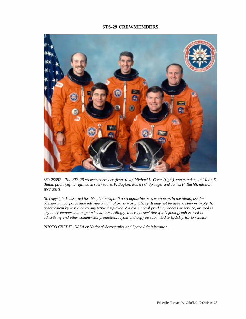
S89-25082 – The STS-29 crewmembers are (front row), Michael L. Coats (right), commander; and John E. Blaha, pilot; (left to right back row) James P. Bagian, Robert C. Springer and James F. Buchli, mission specialists. No copyright is asserted for this photograph. If a recognizable person appears in the photo, use for commercial purposes may infringe a right of privacy or publicity. It may not be used to state or imply the endorsement by NASA or by any NASA employee of a commercial product, process or service, or used in any other manner that might mislead. Accordingly, it is requested that if this photograph is used in advertising and other commercial promotion, layout and copy be submitted to NASA prior to release. PHOTO CREDIT: NASA or National Aeronautics and Space Administration.
Edited by Richard W. Orloff, 01/2001/Page 37
BIOGRAPHICAL DATA MICHAEL L. COATS, 43, captain, USN, is mission commander. Born in Sacramento, Calif., he considers Riverside, Calif., his hometown. Coats is a member of the astronaut class of 1978. Coats was pilot of the 14th Space Shuttle mission (41- D) launched Aug. 30, 1984 marking orbiter Discovery's maiden flight. The 41-D crew earned the nickname "Icebusters" because of their successful removal of hazardous ice particles from the orbiter using the remote manipulator system. The flight included several "firsts:" The first time three communications satellites were deployed during one mission; the first "Frisbee" satellite deployment; and the first time a commercial payload specialist flew aboard the Shuttle. Coats has logged more than 144 hours in space. He earned a B.S. degree from the United States Naval Academy in 1968, a M.S. degree in administration of science and technology from George Washington University in 1977, and a M.S. in aeronautical engineering from the U.S. Naval Postgraduate School in 1979. Coats became a naval aviator in September 1969 and served 25 months as an A-7E pilot aboard the USS Kittyhawk. During that time, he flew 315 combat missions in Southeast Asia. Coats, in 1974, attended test pilot training. Following his training, he was project officer and the test pilot for the A-7 and A-4 aircraft at the Strike Aircraft Test Directorate and served as a flight instructor at the U.S. Naval Test Pilot School from April 1976 to May 1977. He has logged more than 4,700 hours flying time and 400 carrier landings in 22 different types of aircraft. JOHN E. BLAHA, 46, colonel, USAF, is pilot. He was born in San Antonio, Texas. Blaha, making his first flight, is a member of the astronaut class of 1980. He has been an ascent, orbit, planning and entry capsule communicator (CAPCOM) in the Mission Control Center for seven Shuttle flights. Blaha was lead CAPCOM for the STS 41-D and STS 41-G missions. He served as the astronaut office representative of the Space Shuttle ascent/abort reassessment team and the orbital maneuvering system/reaction control system reassessment group. Blaha earned a B.S. degree in engineering science from the U.S. Air Force Academy in 1965 and a M.S. degree in astronautical engineering from Purdue University in 1966. He received his pilot wings in 1967. He then served as an operational pilot flying A-37, F-4, F-102 and F-106 aircraft and completed 361 combat missions in Southeast Asia. Blaha attended the USAF Aerospace Research Pilot School in 1971 and later served as an instructor pilot at the test pilot school. He served as a test pilot working with the Royal Air Force in the United Kingdom for 3 years. Blaha also has worked for the Assistant Chief of Staff, Studies and Analyses at USAF Headquarters in the Pentagon. He has logged 4,300 hours of flying time in 32 different aircraft. JAMES F. BUCHLI, 43, colonel, USMC, is mission specialist one (MS-1). Although born in New Rockford, N.D., Buchli considers Fargo, N.D., his hometown. He is a member of the astronaut class of 1978. Buchli was a mission specialist on STS 51-C launched on Jan. 24, 1985. The first Department of Defense mission included deployment of a modified inertial upper stage from the Space Shuttle Discovery. He next flew Oct. 30, 1985 as a mission specialist on STS 61-A, the West German Spacelab D1 mission. That mission was the first to carry eight crewmembers, the largest crew to fly in space and the first in which payload activities were controlled from outside the United States. Buchli has logged a total of 243 hours in space. He earned a B.S. degree in aeronautical engineering from the U.S. Naval Academy in 1967 and a M.S. degree in aeronautical engineering systems from the University of West Florida in 1975. Following graduation from the U.S. Naval Academy and his commission in the USMC, Buchli served for 1 year in the Republic of Vietnam. He then completed naval flight officer training and was assigned to Marine fighter/attack squadrons in Hawaii, Japan and Thailand. He has logged 3,500 hours flying time, 3,300 hours in jet aircraft.
Edited by Richard W. Orloff, 01/2001/Page 38
BIOGRAPHICAL DATA ROBERT C. SPRINGER, 46, colonel, USMC, is mission specialist two (MS-2). Although born in St. Louis, he considers Ashland, Ohio, his hometown. Springer is a member of the astronaut class of 1980 and will be making his first space flight. He has worked in the Mission Control Center as a CAPCOM for seven flights and was responsible for Astronaut Office coordination of design requirements reviews and design certification reviews, part of the total recertification and reverification of the National Space Transportation System prior to STS-26's return to flight. Springer earned a B.S. degree in naval science from the U.S. Naval Academy in 1964 and a M.S. in operations research and systems analysis from the U.S. Naval Postgraduate School in 1971. After receiving a USMC commission, Springer received his aviator wings in August 1966 and was assigned to VMFA-513 at the Marine Corps Air Station in Cherry Point, N.C., where he flew F-4 aircraft. He then served in Southeast Asia where he flew F-4s and completed 300 combat missions. In June 1968, Springer served as an advisor to the Republic of Korea Marine Corps in Vietnam and flew 250 combat missions in 01 "Bird Dogs" and UH1 "Huey" helicopters. Springer attended Navy Fighter Weapons School (Top Gun) and in 1975 graduated from the U.S. Navy Test Pilot School in Patuxent River, Md. He has served as a test pilot for more than 20 different fixed- and rotary-wing aircraft and performed the first flights in the AHIT helicopter. Springer has logged more than 3,500 hours flying time, including 3,000 hours in jet aircraft. JAMES P. BAGIAN, MD, 36, is mission specialist three (MS- 3). This will be his first space flight. Born in Philadelphia, he is a member of the astronaut class of 1980. Bagian participated in the planning and provision of emergency medical and rescue support for the first six Shuttle flights and has participated in the verification of Space Shuttle flight software. In 1986, Bagian became an investigator for the 51-L accident board and has been responsible for the development of the pressure suit and other crew survival equipment astronauts now use on Shuttle missions. He earned a B.S. degree in mechanical engineering from Drexel University in 1973 and a doctorate in medicine from Thomas Jefferson University in 1977. Bagian worked as a process engineer for the 3M Company in 1973 and later as a mechanical engineer at the U.S. Naval Air Test Center at Patuxent River, Md. He worked as a flight surgeon and research medical officer at the Johnson Space Center in 1978 while completing his studies at the USAF Flight Surgeons School and USAF School of Aerospace Medicine in San Antonio, Texas. An active participant in the mountain rescue community, Bagian has a private pilot's license and has logged more than 1,000 hours flying time in propeller and jet aircraft, helicopters and gliders.
Edited by Richard W. Orloff, 01/2001/Page 39
SPACE SHUTTLE PROGRAM MANAGEMENT NASA HEADQUARTERS Dr. James C. Fletcher Administrator Dale D. Myers Deputy Administrator RADM Richard H. Truly Associate Administrator for Space Flight George W. S. Abbey Deputy Associate Administrator for Space Flight Arnold D. Aldrich Director, National Space Transportation Program Richard H. Kohrs Deputy Director, NSTS Program (located at Johnson Space Center Robert L. Crippen Deputy Director, NSTS Operations (located at Kennedy Space Center) David L. Winterhalter Director, Systems Engineering and Analyses Gary E. Krier Acting Director, Operations Utilization Joseph B. Mahon Deputy Associate Administrator for Space Flight (Flight Systems) Charles R. Gunn Director, Unmanned Launch Vehicles and Upper Stages George A. Rodney Associate Administrator for Safety, Reliability, Maintainability and Quality Assurance Robert O. Aller Associate Administrator for Operations Eugene Ferrick Director, Space Network Division Robert M. Hornstein Director, Ground Network Division JOHNSON SPACE CENTER, HOUSTON, TX Aaron Cohen Director Paul J. Weitz Deputy Director Richard A. Colonna Manager, Orbiter and GFE Projects Donald R. Puddy Director, Flight Crew Operations Eugene F. Kranz Director, Mission Operations Henry O. Pohl Director, Engineering Charles S. Harlan Director, Safety, Reliability and Quality Assurance KENNEDY SPACE CENTER, FL Forrest S. McCartney Director Thomas E. Utsman Deputy Director; Director, Shuttle Management and Operations Robert B. Sieck Launch Director George T. Sasseen Shuttle Engineering Director John J. Talone STS-29 Flow Director James A. Thomas Director, Safety, Reliability and Quality Assurance John T. Conway Director, Payload Management and Operations MARSHALL SPACE FLIGHT CENTER, HUNTSVILLE, AL James R. Thompson Jr. Director Thomas J. Lee Deputy Director William R. Marshall Manager, Shuttle Projects Office Dr. J. Wayne Littles Director, Science and Engineering Alexander A. McCool Director, Safety, Reliability and Quality Assurance Gerald W. Smith Manager, Solid Rocket Booster Project Joseph A. Lombardo Manager, Space Shuttle Main Engine Project Jerry W. Smelser Acting Manager, External Tank Project

Edited by Richard W. Orloff, 01/2001/Page 40
AMES RESEARCH CENTER, MOUNTAIN VIEW, CA Dr. Dale L. Compton Acting Director Victor L. Peterson Acting Deputy Director AMES-DRYDEN FLIGHT RESEARCH FACILITY, EDWARDS, CA Martin A. Knutson Site Manager Theodore G. Ayers Deputy Site Manager Thomas C. McMurtry Chief, Research Aircraft Operations Division Larry C. Barnett Chief, Shuttle Support Office GODDARD SPACE FLIGHT CENTER, GREENBELT, MD Dr. John W. Townsend Director Gerald W. Longanecker Director, Flight Projects Robert E. Spearing Director, Operations and Data Systems Daniel A. Spintman Chief, Networks Division Vaughn E. Turner Chief, Communications Division Dr. Dale W. Harris TDRS Project Manager Charles M. Hunter TDRS Deputy Project Manager Gary A. Morse Network Director

Edited by Richard W. Orloff, 01/2001/Page 41
SHUTTLE FLIGHTS AS OF MARCH 1989 27 TOTAL FLIGHTS OF THE SHUTTLE SYSTEM -- 2 SINCE RETURN TO FLIGHT
STS-51L 01/28/86 STS-61A
10/30/85 - 11/06/85
STS-51F 07/29/85 - 08/06/85
STS-61C 01/12/86 - 01/18/86
STS-51B 04/29/85 - 05/06/85
STS-26 09/29/88 - 10/03/88
STS-9 11/28/83 - 12/08/83
STS-41G 10/05/84 - 10/13/84
STS-51-I 08/27/85 - 09/03/85
STS-5 11/11/82 - 11/16/82
STS-41C 04/06/84 - 04/13/84
STS-51G 06/17/85 - 06/24/85
STS-4 06/27/82 - 07/04/82
STS-41B 02/03/84 - 02/11/84
STS-51D 04/12/85 - 04/19/85
STS-3 03/22/82 - 03/30/82
STS-8 08/30/83 - 09/05/83
STS-51C 01/24/85 - 01/27/85
STS-27 12/02/88 - 12/06/88
STS-2 11/12/81 - 11/14/81
STS-7 06/18/83 - 06/24/83
STS-51A 11/08/84 - 11/16/84
STS-61B 11/26/85 - 12/03/85
STS-1 04/12/81 - 04/14/81
STS-6 04/04/83 - 04/09/83
STS-41D 08/30/84 - 09/05/84
STS-51J 10/03/85 - 10/07/85
OV-102
Columbia (7 flights)
OV-099 Challenger (10 flights)
OV-103 Discovery (7 flights)
OV-104 Atlantis
(3 flights)