Embed Size (px)
Citation preview
Space ShuttleSpace Shuttle

Space Shuttle - DevelopmentSpace Shuttle - Development
Problem:Problem: NASA’s Apollo missions, although NASA’s Apollo missions, although spectacular, required dedicated vehicles with limited spectacular, required dedicated vehicles with limited utility for other space exploration projects. The best utility for other space exploration projects. The best example of that limitation was the Huge Saturn V that example of that limitation was the Huge Saturn V that was best suited for lunar missions.was best suited for lunar missions.
A solution to the problem of space access for research, A solution to the problem of space access for research, academia, industry, and other agencies was thought academia, industry, and other agencies was thought to lie in replacing expendable vehicles with reusable to lie in replacing expendable vehicles with reusable launchers.launchers.
NASA’s solution:NASA’s solution: Develop a universal, reusable booster Develop a universal, reusable booster that could be used for all space flight missions - from that could be used for all space flight missions - from orbital satellites to deep space explorationorbital satellites to deep space exploration

Space Shuttle - DevelopmentSpace Shuttle - Development
One possible solution: One possible solution:
A DynaSoar-like A DynaSoar-like manned glider launched manned glider launched on an inexpensive on an inexpensive expendable booster expendable booster like the Titan or Atlaslike the Titan or Atlas
Problem 1: Problem 1: The USAF needed heavy-lift capability and a high-lift reentry vehicle The USAF needed heavy-lift capability and a high-lift reentry vehicle for its surveillance programsfor its surveillance programs
Problem 2: Problem 2: Budget limitations mandated a combined NASA-USAF launch Budget limitations mandated a combined NASA-USAF launch vehiclevehicle

Space Shuttle - DevelopmentSpace Shuttle - Development
Proposed Proposed solution to solution to Congress: Congress:
Replace all Replace all expendablexpendable boosters e boosters with a with a single, single, reusable, reusable, versatile versatile boosterbooster

Space Shuttle - DevelopmentSpace Shuttle - Development
NASA’s solution approved by Congress:NASA’s solution approved by Congress: Develop a large universal booster for all Develop a large universal booster for all space flight missions - military, orbital and space flight missions - military, orbital and deep spacedeep space
USAF requirement 1:USAF requirement 1: a 15’ x 60’ payload a 15’ x 60’ payload capacitycapacity
USAF requirement 2:USAF requirement 2: Winged vehicle with Winged vehicle with sufficient reentry lift to provide a 1,500 mi sufficient reentry lift to provide a 1,500 mi cross-range capability (land at alternate sites cross-range capability (land at alternate sites and/or land after 1 orbit)and/or land after 1 orbit)

Space Shuttle - DevelopmentSpace Shuttle - Development
Ballistic vehiclesproduce little liftbut high heating.Winged (highlift) vehiclesreduce retentry forces, but increase total heating but with a lower max temp. Mercury,Gemini, Apollocapsules are inbetween.

Space Shuttle - DevelopmentSpace Shuttle - Development
NASA’s ultimate solution: NASA’s ultimate solution: Large, versatile, reusable booster useful for Large, versatile, reusable booster useful for all space flight missions with a 15’ x 60’ payload capacity and a all space flight missions with a 15’ x 60’ payload capacity and a winged reentry vehicle with a 1,500 mi cross-range capability.winged reentry vehicle with a 1,500 mi cross-range capability.
First approximation:First approximation: A large lifting body similar to those tested in the A large lifting body similar to those tested in the 1950s and early 1960s (X-24 and HL-10 gliders shown below), but 1950s and early 1960s (X-24 and HL-10 gliders shown below), but with added boosters.with added boosters.

Space Shuttle - DevelopmentSpace Shuttle - Development
Early design conceptsEarly design concepts

Space Shuttle - DevelopmentSpace Shuttle - Development
Early design conceptsEarly design concepts
Lockheed Star ClipperLockheed Star Clipper

Space Shuttle - DevelopmentSpace Shuttle - Development
Early design concepts Early design concepts Chrysler reusable launcher and orbiterChrysler reusable launcher and orbiter

Space ShuttleSpace Shuttle
Early design Early design concepts concepts
Martin Marietta dual Martin Marietta dual
fly-back booster fly-back booster and orbiterand orbiter

Space Shuttle - DevelopmentSpace Shuttle - Development
Early design Early design concepts concepts
Sketch of processing Sketch of processing
operations operations envisioned at KSC envisioned at KSC circa 1969circa 1969

Space Transportation Space Transportation SystemSystem
Final DesignFinal Design

Space Shuttle - DevelopmentSpace Shuttle - Development
Design concept and approval for NASA Space Design concept and approval for NASA Space Transportation System (STS) was completed in Transportation System (STS) was completed in 19721972
1. Reusable Orbiter with 15’ x 60’ payload bay1. Reusable Orbiter with 15’ x 60’ payload bay
2. Additional propulsion engines attached to the 2. Additional propulsion engines attached to the OrbiterOrbiter
3. External tank to carry propellants3. External tank to carry propellants
4. Solid rocket boosters for majority of lift on first 4. Solid rocket boosters for majority of lift on first stagestage

Space Shuttle - DevelopmentSpace Shuttle - Development
Contracts for the STS were awarded in 1972-73Contracts for the STS were awarded in 1972-73

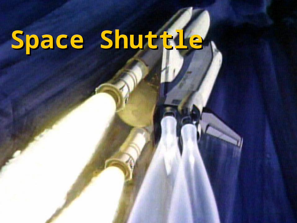
Space Shuttle mission configurationSpace Shuttle mission configuration

Space Shuttle OrbiterSpace Shuttle Orbiter

Space Shuttle OrbiterSpace Shuttle Orbiter
Reusable winged reentry vehicleReusable winged reentry vehicle
Composition – Aluminum alloy similar to commercial aircraftComposition – Aluminum alloy similar to commercial aircraft
Structure - 122' long, 57' high, 78' wingspanStructure - 122' long, 57' high, 78' wingspan
Launch weight - approximately 230,000 lbLaunch weight - approximately 230,000 lb
Cargo bay - 15' x 60' Cargo bay - 15' x 60'
Design lifetime - 100 flightsDesign lifetime - 100 flights
Crew – 5 to 7 (10 max for emergencies)Crew – 5 to 7 (10 max for emergencies)
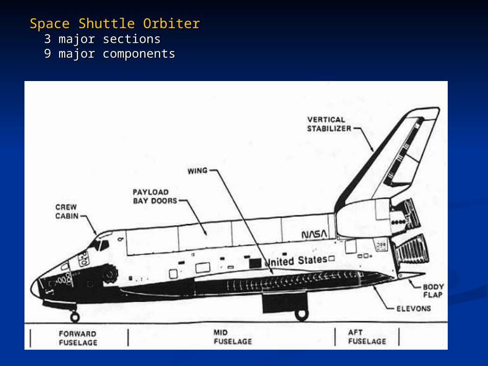
Space Shuttle OrbiterSpace Shuttle Orbiter 3 major sections3 major sections 9 major components 9 major components

Space Shuttle OrbiterSpace Shuttle Orbiter
9 major components
1. Forward fuselage - the top and bottom sections which surrounds the crew compartment
2. Wings - aluminum alloy structure that include elevons for longitudinal control
3. Mid fuselage - 60 ft midsection that is the primary load carrying structure
4. Payload bay doors - graphite epoxy for light weight
5. Aft fuselage - truss-type structure that transfers SSME thrust to mid fuselage and ET
6. Forward Reaction Control System (RCS)
7. Vertical tail - aluminum alloy structure that includes combine rudder and speed brake
8. OMS/RCS systems • OMS - Orbital Maneuvering System used to change or alter orbit (higher thrust
than RCS) • RCS - Reaction Control System is used for spacecraft attitude control
9. Body flap - protect SSMEs during reentry and help provide aerodynamic control

Space Shuttle OrbiterSpace Shuttle Orbiter

Solid Rocket BoostersSolid Rocket Boosters

Space Shuttle Solid Rocket Boosters (SRBs)Space Shuttle Solid Rocket Boosters (SRBs)
Reusable, solid fuel booster pair provides 72% of liftoff thrustReusable, solid fuel booster pair provides 72% of liftoff thrust
Structure – 4 motor sections + recovery frustumStructure – 4 motor sections + recovery frustum
Length – 149.2’Length – 149.2’
Diameter – 12.2’Diameter – 12.2’
Weight – 1,300,000 lb loadedWeight – 1,300,000 lb loaded
Thrust – 3,300,000 lbThrust – 3,300,000 lbff
Burn time – 2 min 10 secBurn time – 2 min 10 sec
Propellant – aluminum powder (fuel) + ammonium perchlorate (oxidizer)Propellant – aluminum powder (fuel) + ammonium perchlorate (oxidizer)
IIspsp – 269 sec – 269 sec
Boost altitude – 150,000’Boost altitude – 150,000’
Recovery – parachute + floatation devicesRecovery – parachute + floatation devices

Space Shuttle Solid Rocket BoostersSpace Shuttle Solid Rocket Boosters

SRB SegmentsSRB Segments - Assembly - Assembly
SRBs are bolted to the Mobile Launcher Platform inside the Vehicle Assembly Building (VAB)

SRB FuelSRB Fuel
SRB solid fuel compositionSRB solid fuel composition
Ammonium perchlorate (oxidizer) 69.6% Ammonium perchlorate (oxidizer) 69.6% Powdered aluminum (fuel) 16% Powdered aluminum (fuel) 16% Iron oxide (catalyst) 0.4% Iron oxide (catalyst) 0.4% HTPB polymer binder 12% HTPB polymer binder 12% Epoxy curing agent 2% Epoxy curing agent 2%

Space Shuttle Main Space Shuttle Main EnginesEngines

SSMEs - OperationsSSMEs - Operations
The Space Shuttle Main Engine (SSME) is a dual-stage (staged), The Space Shuttle Main Engine (SSME) is a dual-stage (staged), regeneratively cooled (circulated propellant), reusable, variable regeneratively cooled (circulated propellant), reusable, variable thrust, high-performance, LOX + LH2 rocket engine with thrust thrust, high-performance, LOX + LH2 rocket engine with thrust vectoring using hydraulic actuatorsvectoring using hydraulic actuators
Each SSME is performance rated and assigned duty for specific Each SSME is performance rated and assigned duty for specific missions based on the vehicle performance requirements missions based on the vehicle performance requirements (primarily the payload mass and orbital inclination) and engine (primarily the payload mass and orbital inclination) and engine performance parametersperformance parameters
All three engines selected for a mission are matched for All three engines selected for a mission are matched for comparable performancecomparable performance

SSMEsSSMEs

Space Shuttle Main Engines (SSME)Space Shuttle Main Engines (SSME)
Reusable, single-start liquid bipropellant enginesReusable, single-start liquid bipropellant engines
Length – 14’Length – 14’
Diameter – 7.5’Diameter – 7.5’
Weight – 7,480 lbWeight – 7,480 lb
Thrust – 513,250 lbThrust – 513,250 lbff (109% in space/vacuum) (109% in space/vacuum)
Burn time – 8 minBurn time – 8 min
PropellantsPropellants Liquid hydrogenLiquid hydrogen Liquid oxygen Liquid oxygen
IIspsp – 452 sec – 452 sec
Lifetime – 100 starts (7.7 hr accumulated operational time)Lifetime – 100 starts (7.7 hr accumulated operational time)
Mixture ratio – 6:1Mixture ratio – 6:1

Space Shuttle Main Space Shuttle Main Engine (SSME)Engine (SSME)

External TankExternal Tank

Space Shuttle External TankSpace Shuttle External Tank
The Space Transportation System’s External Tank is one of the The Space Transportation System’s External Tank is one of the four major components that was contracted for development four major components that was contracted for development and production by NASA in 1972and production by NASA in 1972
Lockheed-Martin won the ET contract and moved its fabrication Lockheed-Martin won the ET contract and moved its fabrication plant to the NASA facilities in Machoud, Louisianaplant to the NASA facilities in Machoud, Louisiana
The Machoud plant’s location on the Gulf of Mexico allowed The Machoud plant’s location on the Gulf of Mexico allowed shipping the completed External Tanks to the Kennedy Space shipping the completed External Tanks to the Kennedy Space Center by bargeCenter by barge The ET is the largest component on the STS, and could not be The ET is the largest component on the STS, and could not be
shipped by rail or by cargo aircraftshipped by rail or by cargo aircraft
The Machoud plant will be turned over to Boeing for The Machoud plant will be turned over to Boeing for conversion into the upper-stage Ares I fabrication facility as conversion into the upper-stage Ares I fabrication facility as the STS project comes to an endthe STS project comes to an end

Space Shuttle External TankSpace Shuttle External Tank
Super-lightweight aluminum-lithium dual tank Super-lightweight aluminum-lithium dual tank and thrust structure (non-reusable)and thrust structure (non-reusable)
Length – 154.2’Length – 154.2’ Diameter – 27.5’Diameter – 27.5’ Weight Weight
1,668,000 lb loaded1,668,000 lb loaded 78,100 lb empty78,100 lb empty
LOX weight – 1,359,000 lbLOX weight – 1,359,000 lb LH2 weight – 226,000 lbLH2 weight – 226,000 lb

ET TransportationET Transportation
Fabricated External Fabricated External Tanks are placed on a Tanks are placed on a barge in the Michoud, barge in the Michoud, Louisiana plant ant Louisiana plant ant towed to the Kennedy towed to the Kennedy Space Center by tugSpace Center by tug

ET – The FutureET – The Future
NASA Ares I and Ares V vehicles were to employ similar NASA Ares I and Ares V vehicles were to employ similar tanks to the ET LH2-LOX structuretanks to the ET LH2-LOX structure
Ares I is the cargo launcher consisting of a 5-segment SRB, with Ares I is the cargo launcher consisting of a 5-segment SRB, with an upper liquid fuel booster an upper liquid fuel booster LH2 & LOX propellantsLH2 & LOX propellants Approximately 1/5 the volume of the STS ETApproximately 1/5 the volume of the STS ET Uses only spray-on insulation since crew vehicle rides on top of the Uses only spray-on insulation since crew vehicle rides on top of the
boosterbooster No insulation shedding hazardNo insulation shedding hazard
Ares V uses two 5-segment SRB boosters with 5 RS-68 second-Ares V uses two 5-segment SRB boosters with 5 RS-68 second-stage engines stage engines RS-68 are used on the Delta IVRS-68 are used on the Delta IV
Second-stage uses the same ET structure with separate LH2 and Second-stage uses the same ET structure with separate LH2 and LOX tanks separated with an intertank structureLOX tanks separated with an intertank structure

Launchers – Past, Present, and FutureLaunchers – Past, Present, and Future

Passive Thermal Passive Thermal Protection SystemProtection System

Orbiter Thermal Protection System
Orbiter TPS - Refractory coated glass tilesOrbiter TPS - Refractory coated glass tiles
Reinforced Carbon-Carbon (RCC)Reinforced Carbon-Carbon (RCC) - Used on the nose cap and wing leading edges - Used on the nose cap and wing leading edges where where reentry temperatures exceed 1260° C (2300° F) reentry temperatures exceed 1260° C (2300° F)
High-temperature Reusable Surface Insulation (HRSI)High-temperature Reusable Surface Insulation (HRSI) - Used - Used primarily on the Orbiter belly where reentry temperatures are below primarily on the Orbiter belly where reentry temperatures are below 1260° C 1260° C
Fibrous Refractory Composite Insulation (FRCI)Fibrous Refractory Composite Insulation (FRCI) - FRCI tiles that - FRCI tiles that have replaced some of the HRSI 22 lb tiles provide improved have replaced some of the HRSI 22 lb tiles provide improved strength, durability, resistance to coating crackingstrength, durability, resistance to coating cracking
Toughened Unipiece Fibrous Insulation (TUFI) Toughened Unipiece Fibrous Insulation (TUFI) - A stronger, more - A stronger, more durable tile that is replacing high and low temperature tiles in high-durable tile that is replacing high and low temperature tiles in high-abrasion areas abrasion areas
Low-temperature Reusable Surface Insulation (LRSI)Low-temperature Reusable Surface Insulation (LRSI) - Originally - Originally used on the upper fuselage, but now mostly replaced by AFRSI used on the upper fuselage, but now mostly replaced by AFRSI

Orbiter Thermal Protection SystemOrbiter Thermal Protection System
Orbiter passive thermal tile typesOrbiter passive thermal tile types
Fibrous blanketsFibrous blankets
Advanced Flexible Reusable Surface Insulation (AFRSI)Advanced Flexible Reusable Surface Insulation (AFRSI) - - Quilted, flexible surface insulation blankets used where Quilted, flexible surface insulation blankets used where reentry temperatures are below 649° C (1200° F) reentry temperatures are below 649° C (1200° F)
Felt reusable surface insulation (FRSI)Felt reusable surface insulation (FRSI) - Nomex felt blankets - Nomex felt blankets that are used on the upper regions of the Orbiter where that are used on the upper regions of the Orbiter where temperatures are below 371° C (700° F)temperatures are below 371° C (700° F)

TPS SurfacesTPS Surfaces
Lower Surface
Upper Surface
TPS Legend
HRSI (Black) TilesLRSI (White) TilesAFRSI Blankets
GlassExposed Metallic Surfaces
FRSIRCC

Bonded TPSBonded TPS
HRSI tiles on the Orbiter ~19,700 (9 lb), 525 (22 lb)
TUFI tiles on the Orbiter 306 (8 lb)
FRCI tiles on the Orbiter 2,950 (12 lb)
LRSI tiles on the Orbiter 725 (9 lb), 77 (12 lb)
FIB blanket area on the Orbiter 2,123 sq ft
FRSI sheet area on the Orbiter 2,024 sq ft

Electrical Power Electrical Power SystemSystem

Orbiter EPSOrbiter EPS
Electrical power for the Orbiter is provided by three fuel cells Electrical power for the Orbiter is provided by three fuel cells powered by liquid hydrogen and liquid oxygenpowered by liquid hydrogen and liquid oxygen
Fuel cells for manned spacecraft were first used in the Gemini Fuel cells for manned spacecraft were first used in the Gemini program program Developed for the Apollo missions because of their byproduct – Developed for the Apollo missions because of their byproduct –
waterwater
Weight savings from not carrying water was a greater Weight savings from not carrying water was a greater advantage than the disadvantages of the added weight, volume advantage than the disadvantages of the added weight, volume and complexity of the cryogenic reactant storageand complexity of the cryogenic reactant storage
To improve the electrical power system (EPS) efficiency and To improve the electrical power system (EPS) efficiency and reliability, the Orbiter’s fuel cell system was designed to power reliability, the Orbiter’s fuel cell system was designed to power the entire STSthe entire STS
EPSEPS

EPS – Fuel CellsEPS – Fuel Cells
Fuel cell advantages over conventional Fuel cell advantages over conventional spacecraft powerspacecraft power
Water byproduct Water byproduct
Efficient conversion of reactant mass into electrical Efficient conversion of reactant mass into electrical energy energy
High power output (7-10 kW per cell) High power output (7-10 kW per cell)
Power output is dependent only on load Power output is dependent only on load requirements (small standby power needed) requirements (small standby power needed)

EPS – Fuel CellsEPS – Fuel Cells
Fuel cell advantages over conventional Fuel cell advantages over conventional spacecraft powerspacecraft power
Modular components could be replaced as necessary Modular components could be replaced as necessary (during processing, not on orbit)(during processing, not on orbit)
Vibration and noise free operation Vibration and noise free operation
Low maintenance required during mission operations Low maintenance required during mission operations
Relatively low weight Relatively low weight
Liquid oxygen was also required for crew life supportLiquid oxygen was also required for crew life support

EPS – Fuel CellsEPS – Fuel Cells
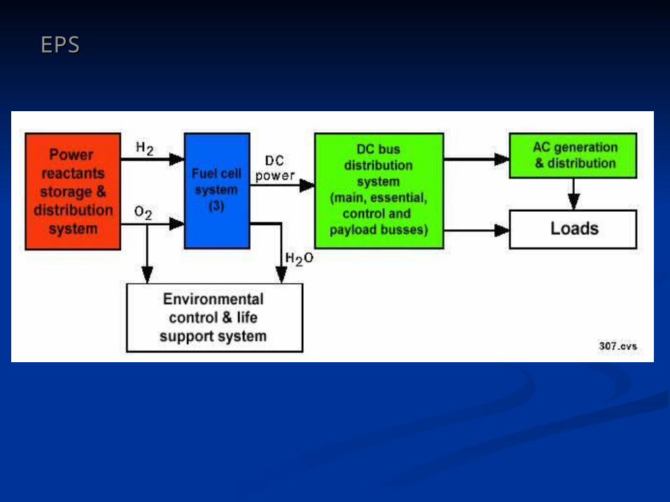
Each fuel cell is Each fuel cell is connected to an connected to an independent, isolated independent, isolated dc busdc bus All three buses have All three buses have
cross-tiescross-ties Crossover circuits are Crossover circuits are
also provided for a also provided for a number of the number of the subdivided busessubdivided buses
Alternating current is Alternating current is generated on three generated on three independent ac buses independent ac buses connected to the three connected to the three main dc bus linesmain dc bus lines

Orbital Maintenance Orbital Maintenance System (OMS) and System (OMS) and
Reaction Control System Reaction Control System (RCS)(RCS)

OMS/RCS SystemOMS/RCS System
Flight control of the Orbiter beyond the atmosphere is provided Flight control of the Orbiter beyond the atmosphere is provided by the OMS and RCS thrustersby the OMS and RCS thrusters
OMS/RCS functions are under the control of the operational OMS/RCS functions are under the control of the operational software used for Guidance Navigation and Control (GN&C)software used for Guidance Navigation and Control (GN&C)
The OMS and RCS thrusters are combined to furnish both high The OMS and RCS thrusters are combined to furnish both high and low thrust for the Orbiter’s two flight functions on orbitand low thrust for the Orbiter’s two flight functions on orbit Orbit change - OMSOrbit change - OMS Attitude control - RCSAttitude control - RCS

OMS/RCS SystemOMS/RCS System

OMS/RCS SystemOMS/RCS System
Both OMS and RCS thrusters use the same propellantsBoth OMS and RCS thrusters use the same propellants Monomethyl hydrazine – fuelMonomethyl hydrazine – fuel Nitrogen tetroxide – oxidizerNitrogen tetroxide – oxidizer
Thruster placementThruster placement OMS – Only aft thrustersOMS – Only aft thrusters RCS – Both fore and aft thrusters RCS – Both fore and aft thrusters
ThrustThrust OMS thrusters OMS thrusters
6,000 lb (2)6,000 lb (2)
RCS thrusters RCS thrusters 870 lb (38)870 lb (38) 24 lb (4)24 lb (4)

Communications SystemCommunications System

Orbiter CommunicationsOrbiter Communications
UHF (voice)UHF (voice)Duplex and simplexDuplex and simplex
S-band (data and S-band (data and voice)voice)DuplexDuplex
Ku-band – video dataKu-band – video dataDuplexDuplex

Orbiter Communications Data TypesOrbiter Communications Data Types
TelemetryTelemetryDownlink data of the Orbiter's operating conditions and configurations, Downlink data of the Orbiter's operating conditions and configurations, systems, payloads and crew biotelemetry measurementssystems, payloads and crew biotelemetry measurements
CommandCommandUplink data directed to the Orbiter systems to perform functional or Uplink data directed to the Orbiter systems to perform functional or configuration changesconfiguration changes
Rendezvous and trackingRendezvous and trackingOnboard radar and communications system for tracking and performing Onboard radar and communications system for tracking and performing rendezvous with orbiting satellites/spacecraftrendezvous with orbiting satellites/spacecraft
Video Video Video imaging is used onboard, or relayed to ground from the crew cabin or on Video imaging is used onboard, or relayed to ground from the crew cabin or on EVA activities, or from the payload bay, or from the remote manipulator armEVA activities, or from the payload bay, or from the remote manipulator arm
Voice communicationsVoice communicationsIntracommunications between the flight crew members, and between the flight Intracommunications between the flight crew members, and between the flight crew and groundcrew and ground
DocumentationDocumentationPrinted data from the Orbiter's thermal impulse printer system (TIPS)Printed data from the Orbiter's thermal impulse printer system (TIPS)

Orbiter Communications Data TypesOrbiter Communications Data Types
The Orbiter communications system bands include The Orbiter communications system bands include
1. S-band 1. S-band PM (Phase Modulation) PM (Phase Modulation) FM (Frequency Modulation) FM (Frequency Modulation) Payload Payload
2. Ku-band2. Ku-band TDRSS data & video communications TDRSS data & video communications Rendezvous radar Rendezvous radar
3. UHF voice3. UHF voice Ground Ground EVA EVA
Note:Note:Voice communications are also available through the military TACAN unitVoice communications are also available through the military TACAN unit
Other frequencies are used for the Orbiter's navigation subsystems and include C-band Other frequencies are used for the Orbiter's navigation subsystems and include C-band for the radar altimeter, L-band for the GPS and TACAN units, and Ku-band for the for the radar altimeter, L-band for the GPS and TACAN units, and Ku-band for the MSBLS landing systemMSBLS landing system

Command and Data Command and Data Handling SystemHandling System

Command & Data Handling System
The Orbiter functions and operations are The Orbiter functions and operations are managed by a computerized data managed by a computerized data management system called the Command management system called the Command and Data Handling Systemand Data Handling System
Primary data management is provided by Primary data management is provided by five identical IBM 101 digital computers five identical IBM 101 digital computers running in parallel for redundancyrunning in parallel for redundancy
Secondary data management is furnished Secondary data management is furnished by a network of 24 computerized system by a network of 24 computerized system management units called management units called Multiplexers/Demultiplexers (MDMs)Multiplexers/Demultiplexers (MDMs)
Two dedicated critical event control units Two dedicated critical event control units supply signal and data management for supply signal and data management for launch, orbit, deorbit, and landing phases launch, orbit, deorbit, and landing phases of the Orbiter and STSof the Orbiter and STS
Two tape drives containing command and Two tape drives containing command and data programs are also provided for data programs are also provided for redundancy in flight operation softwareredundancy in flight operation software

C&DH functional block diagram

Command & Data Handling System – MEDS Glass Cockpit Command & Data Handling System – MEDS Glass Cockpit
A full glass cockpit was introduced to the Orbiter lineup A full glass cockpit was introduced to the Orbiter lineup with the installation of the complete upgrade of Atlantis with the installation of the complete upgrade of Atlantis to a digital cockpit display with 11 full-color flat panel to a digital cockpit display with 11 full-color flat panel screensscreens
First mission of Atlantis with the glass cockpit was an First mission of Atlantis with the glass cockpit was an assembly flight to the ISS on STS-101 in May, 2000assembly flight to the ISS on STS-101 in May, 2000
Each of the four Orbiters has been upgraded to a Each of the four Orbiters has been upgraded to a Multifunction Electronic Display System (MEDS) glass Multifunction Electronic Display System (MEDS) glass cockpit cockpit

Fish-eye view of Fish-eye view of the Orbiter's new the Orbiter's new Multifunction Multifunction Electronic Electronic Display Display Subsystem Subsystem (MEDS) glass (MEDS) glass cockpit shown cockpit shown here in the here in the Johnson Space Johnson Space Center's Shuttle Center's Shuttle Mission Mission SimulatorSimulator

Command & Data Handling System – Portable Computers Command & Data Handling System – Portable Computers
Laptop computers were flown for the first Laptop computers were flown for the first time on the Endeavour Orbiter on the time on the Endeavour Orbiter on the first Hubble Space Telescope servicing first Hubble Space Telescope servicing mission during STS-61mission during STS-61
The first Shuttle IBM ThinkPad 750C The first Shuttle IBM ThinkPad 750C laptops were replaced with the IBM laptops were replaced with the IBM 755C ThinkPad in 1994 to become a 755C ThinkPad in 1994 to become a standard Space Shuttle Payload and standard Space Shuttle Payload and General Support Computer (PGSC) for General Support Computer (PGSC) for astronaut and experiment useastronaut and experiment use
Later replacements to the Shuttle laptop Later replacements to the Shuttle laptop computers includes the IBM ThinkPad computers includes the IBM ThinkPad 760XD and a Rendezvous and Proximity 760XD and a Rendezvous and Proximity Operations Program (RPOP) software Operations Program (RPOP) software package to aid in docking and package to aid in docking and rendezvous operations with the rendezvous operations with the International Space StationInternational Space Station

Space Shuttle ProcessingSpace Shuttle Processing

Space Shuttle ProcessingSpace Shuttle Processing
STS processing is a term used to describe the STS processing is a term used to describe the preparations and procedures for readying the Space preparations and procedures for readying the Space Shuttle for its next missionShuttle for its next mission
The STS processing work cycle begins with the The STS processing work cycle begins with the Orbiter’s return to KSC for its coming flightOrbiter’s return to KSC for its coming flight
The processing cycle actually starts with the The processing cycle actually starts with the development of the flight, equipment, and development of the flight, equipment, and operations manifestoperations manifest Planning begins as early as 5 years before the planned Planning begins as early as 5 years before the planned
mission, or in some cases even longermission, or in some cases even longer

Space Shuttle ProcessingSpace Shuttle Processing
Primary processing facilities are at KSCPrimary processing facilities are at KSC
Supporting facilities includeSupporting facilities include Other KSC sites (transportation, logistics, etc.)Other KSC sites (transportation, logistics, etc.) JSCJSC NASA Center – Washington, D.C.NASA Center – Washington, D.C. NASA CentersNASA Centers Primary contractors – worldwide and nationalPrimary contractors – worldwide and national Federal agencies (FAA, NTSB, DoD, etc.)Federal agencies (FAA, NTSB, DoD, etc.) State agenciesState agencies Local contractorsLocal contractors Educational institutionsEducational institutions Media servicesMedia services

Space Shuttle Processing FacilitiesSpace Shuttle Processing Facilities

Space Shuttle ProcessingSpace Shuttle Processing

STS Assembly & STS Assembly & IntegrationIntegration

STS AssemblySTS Assembly
Assembly base - the Assembly base - the Mobile Launcher Mobile Launcher PlatformPlatform
The Mobile Launcher The Mobile Launcher Platform (MLP) was Platform (MLP) was originally designed and originally designed and used for the Apollo-used for the Apollo-Saturn V missionsSaturn V missions
MLP has similar tail MLP has similar tail service masts that are service masts that are used for umbilical used for umbilical connections between the connections between the Ground Service Ground Service Equipment and the Equipment and the launch vehiclelaunch vehicle
These protective covers These protective covers and connections swing and connections swing away from the vehicle away from the vehicle just before liftoffjust before liftoff

STS Assembly – SRB StackingSTS Assembly – SRB Stacking
The completed pair The completed pair of boosters is then of boosters is then mated with the mated with the External Tank at External Tank at the fore (top) and the fore (top) and aft (bottom) attach aft (bottom) attach points that use a points that use a similar bolt and similar bolt and frangible nut pair frangible nut pair as the aft skirt hold as the aft skirt hold down postsdown posts
Further assembly Further assembly and checkout of and checkout of the SRB is the SRB is completed during completed during the mate of the the mate of the Orbiter, and finally Orbiter, and finally at the launch padat the launch pad

STS Assembly – ETSTS Assembly – ET
After preparation, the After preparation, the External Tank is External Tank is then demated from then demated from the transporter, the transporter, rotated, then lifted rotated, then lifted vertically into the vertically into the high bay and mated high bay and mated with the stacked with the stacked SRB pairSRB pair
Total time for the ET Total time for the ET checkout and checkout and preparation is preparation is approximately 70 approximately 70 daysdays

STS AssemblySTS Assembly
Orbiter AttachmentOrbiter Attachment
This begins with the This begins with the Orbiter's attachment to Orbiter's attachment to the External Tank, the External Tank, which itself has been which itself has been attached to the SRBattached to the SRB Structural isolation of Structural isolation of
the SRB from the the SRB from the Orbiter is necessary Orbiter is necessary because of the because of the separation sequence separation sequence during the ascent phase during the ascent phase of flight, and because of of flight, and because of design requirementsdesign requirements

STS AssemblySTS Assembly
Orbiter lift Orbiter lift
After passing over the After passing over the high bay transom, the high bay transom, the Orbiter is lowered near Orbiter is lowered near the External Tank for the External Tank for attachmentattachment
As the Orbiter attains the As the Orbiter attains the correct alignment with the correct alignment with the ET, the lift is halted and ET, the lift is halted and the attachment the attachment procedures beginprocedures begin
Orbiter attachment Orbiter attachment (integration) takes (integration) takes approximately 5 daysapproximately 5 days

STS Assembly CompletionSTS Assembly Completion
RolloutRollout
The nearly-The nearly-completed STS completed STS mounted on mounted on the Mobile the Mobile Launcher Launcher Platform (MLP) Platform (MLP) is carried out is carried out the the launch the the launch pad by the pad by the Crawler Crawler TransporterTransporter

STS AssemblySTS Assembly
CompletionCompletion
Some of the Some of the separation separation ordinance is ordinance is installed in the installed in the vehicle and checked, vehicle and checked, but not wired into but not wired into the firing circuitry of the firing circuitry of the Master Events the Master Events ControllerController
Final connection and Final connection and testing for the pyro testing for the pyro components are components are made as the Shuttle made as the Shuttle vehicle goes vehicle goes through its final through its final launch preparation launch preparation on the padon the pad

STS Launch PreparationsSTS Launch Preparations
Preparations for launch of the STS on the launch pad take approximately one month
Countdown begins three days before launch

The Launch The Launch