Embed Size (px)
Citation preview

NASA-CR-200777
' UNITEDTECHNOLOGIES
JUL 2 1 1995
!:_', •
S'y_--!SHR 16991REVISION: Basic
DATA RIGHTS N
Date: 14 July 1995
SPACE STATION WATER PROCESSORMOSTLY LIQUID SEPARATOR
(aLS)
Final Report
for
Ion Electronics
Contract # NAS8-38250-12
Prepared By
UNITED TECHNOLOGIES CORPORATION
HAMILTON STANDARD SPACE SYTEMS
INTERNATIONAL INC.
Windsor Locks, CT 06096
https://ntrs.nasa.gov/search.jsp?R=19960017622 2018-07-17T06:47:10+00:00Z

UNITEDTECHNOLOGIES SVHSER 16991
REVISION: BasicDATA RIGHTS N
Date: 14 July 1995
SPACE STATION WATER PROCESSORMOSTLY LIQUID SEPARATOR
(MLS)
Final Report
for
Ion Electronics
Contract # NAS8-38250-12
Prepared By
UNITED TECHNOLOGIES CORPORATION
HAMILTON STANDARD SPACE SYTEMS
INTERNATIONAL INC.
Windsor Locks, CT 06096

UNITEDTECHNOLOGIES SVI-'ISER16991
REVISION: Basic
PAGE I OF 87
DATA RIGHTS N
Date:14Su/y1995
SPACE STATION WATER PROCESSOR
MOSTLY LIQUID SEPARATOR
(MLS)
Final Report
for
Ion Electronics
Contract # NAS8-38250-12
Prepared By
UNITED TECHNOLOGIES CORPORATION
HAMILTON STANDARD SPACE SYTEMS
INTERNATIONAL INC.
Windsor Locks, CT 06096
VrcparcdBy :
,,rov David Parker
Approved By: _7_. Z_ _TZ._2J'_-/_ _ _
Kathy F6_erJ
o=o
_ UNITEDTECHNOLOGIES SVHSER 16991
REVISION: BasicPAGE 5 OF 87
DATA RIGHTS N
2. Abstract
This reportpresents theresultsofthedevelopmenttestingconductedunder thiscontracttothe Space
StationWater Processor(WP) MostlyLiquidSeparator(MLS). The MLS unitsbuiltand modifiedduring
this _'Rng demonstrated acceptable air/water separation results in a variety of water conditions with inlet
flow rates ranging from 60 - 960 LB/hr.
3. Summary
Priortothetestingdescn'bedinthisreport,a prototypeMLS was evaluatedatHSSSI duringtheperiod
from the 2nd quater of 1990 to the 3rd quatcr of 1992. Based upon the favorable results of that effort, thecurrent effort was undertaken to further develop tim MLS" technology. The current program, which began
in March 1994 and concluded in July 1995, was undertaken with the objective of developing the nextgeneration MLS for the requirements of the International Space Station Water Processor (ISS WP). A new
MLS design was created that was sized to operate over the full 60 to 960 ro/bx inlet flow range and thatutilized an improved control mechanism to regulate gas venting. MLS units were built and tested to
demonstrate acceptable performance at higher inlet flow rates (up to 960 lb/hr), under a variety of waterconditions.The use ofdevelopmentMLS unitsmade outoftranslucentplasticmaterialwas instrumental
inthesuccessofthisdevelopmentprogram Performancemapping indicatedthatacceptableperformance
can be achieved at 1900 RPM for any water condition with 0% - 14% air in the inlet stream. Severalhardwa_ modifications wcrc made during the cours_ of the program to improve performance, themajority of which were successRd. Test results suggest that maintaining a near-constant backpressum and
RPM within the MLS is of prime importance in providing acceptable performance. Further developmenteffort is recommended.
4. Introduction
The MLS, item 4703, is an integral component in the Waste Water Orbital Replacement Unit (WWORU).The function of thc WWORU isto convert a waste water stream into potable quality water. Waste water
contains free gas along with many other materiais which are prone to foaming. This gas is problematic tothe water processor,flitisnot removed,performanceofthesystemcan degradesignificantly.This ORU
isdescn'bedfurtherinAppendix I1:MLS PlanofTeston page 59.The MLS isresponm'bleforremoving
thefrecgasfrom thewastewaterstream.Waste water,upon enteringthesysteminlet,flowsimmediately
throughtheMostlyLiquidSeparatorwhere freegasisseparated,coUectedand ventedtothecabin,while
thewastewaterisdeliveredtostorageorisdrawn bytheprocesspump intotheprocessor.
_ UNITEDTECHNOLOGIES SVHSER 16991
REVISION: Basic
PAGE 2 OF 87
DATA RIGHTS N
1. Table of Contents
1. TABLE OF CONTENTS
2. _LBST]RACT__
3. SUMMARY ........
4. INTRODUCTION
======:=====7
6. DESCRIPTION OF TEST ............................................ 9
6.1 C-'IZANWATER................................................................................................................................... 11
6.1.1 TEST PERIOD" Dec 19, 1994 -Jan26, 1995 .......................................................................... 116.1.2 TEST PERIOD: Jan 27, 1995 - Feb 1, 1995 .............................................................................. 11
6.1.3 TEST PERIOD: Feb 2, 1995 - Feb 13, 1995 ............................................................................... 126.1.4 TEST PERIOD: Feb 14, 1995 - Mar 2, 1995 ............................................................................... 146.1.5 TEST PERIOD: Mar 3, 1995 - Mar 12, 1995 .............................................................................. 20
6.2 SOAP& WATER ................................................................................................................................. 22
6.2.1TEST PERIOD: Mar 13,1995 -Mar 14,1995,Water CarryoverPerformance............................22
6.2.2TEST PERIOD: Mar 14,1995 -Mar 28, 1995, Air CarryoverPerformance...............................236.3SHOWER WATER ................................................................................................................................26
6.3.1TEST PERIOD: Mar 29, 1995 -Apr I0,1995,Air CarryoverPerformance................................27
6.3.2TEST PERIOD: Apr 12,1995 -Apr 13,1995,Water CarryoverPerformance............................30
6.3.3TEST PERIOD: Apr 17,1995 -Apr 28, 1995,TestingUsingP/N SVSKI21960-1 InletDisk.....316.4_ED PERFOP._,IANCETESTING....................................................................................................34
6.4.1TEST PERIOD: May I,1995 -May 9,1995,MetalMLS CleanWater Performance..................34
6.4.2TEST PERIOD: May 12,1995 -May 14,1995,Backpressum Valve...........................................38
6.4.3 TEST PERIOD: May 15, 1995 - May 17, 1995, Metal MLS Water Carryover Performance inShower Water ...................................................................................................................................... 39
6.4.4 TEST PERIOD: May 18, 1995 - June 6, 1995, Metal bILS AirCarryover Performance in ShowerWater .................................................................................................................................................. 40
6.4.5 TEST PERIOD: June 7, 1995 - July 6, 1995, Metal MLS Extended Performance Testing ........... 49
6.4.6 TEST PERIOD: July 7, 1995 - July 11, 1995, Metal MLS Post-Test Performance Mapping ........ 49
7. OBSERVATIONS AND CONCLUSIONS ._.53
7.10BSF._VATZONS .................................................................................................................................. 537.2 CONCt.USIONS.................................................................................................................................... 54
$. RECOM2H_NDATIONS_ ................ ---_-..... - ........................ 55
9. APPENDIX I:_ MINI-SPECIFICATION ,56
I0.APPENDIX II:MLS PLAN OF TEST 59
10.1 INTRODUCTION: ...............................................................................................................................62

_ UNITED
TECHNOLOGIES SVHSER 16991REVISION: Basic
PAGE 3 OF 87
DATA RIGHTS N
10.2 BACKGROUND:................................................................................................................................. 6410.3 TESF DESCRIFFION:............................................................................................................................ 64
10.3.1 Tes_ Objectives: .......................................................................................................................... 6410.4 TF.STSCHED_r_: ................................................................................................................................ 6510.5 _ CONDITIONS.............................................................................................................................. 66
10.5.1 _Setup Test, Both Separators: ......................................................................................... 6610.6 PERFORMANCETE,_, BOTH SEPARATORS............................................................................................. 67
10.6.1 STAGE I, Clean Water ............................................................................................................... 67
10.6.2 STAGE 2, VL,gin Igepon Soap .................................................................................................... 7110.6.3 Zero C_a-avityPerfommu¢:_ Plastic MLS Only ............................................................................... 7110.6.4 STAGE 3, Real Waste Water ....................................................................................................... 71
10.7 _ _ST_O, METAL ML,S ONLY....................................................................................................... 7210.8 TESTSYSTEM/ENVIRONME2¢I":.............................................................................................................. 74
10.8.1 Tes_ System: ............................................................................................................................... 7410.9 TESTENVmONMENT:.......................................................................................................................... 74
11. APPENDIX I[I: MLS EXTENDED PERFORMANCE TEST PLAN .............. 75
11.1 IN'_ODUC'_ON ................................................................................................................................ 78
11.2 TY.STDESCRIFTION........................................................................................................................... 78
11.2.1 Test Object_es ......................................................................................................................... 7811.2.2 Test Schedule ........................................................................................................................... 78
11.3 TF.STCONDrFIONS ............................................................................................................................ 79
11.3.1 Checkout .................................................................................................................................. 7911.3.2 Verification .............................................................................................................................. 8111.3.3 Extended Performance Test ...................................................................................................... 83
11.3"4 Check for Performance Degradation ......................................................................................... 8511.4 _ SYSTEM AND ENVIRONMENT.................................................................................................... 86
11.4.1 Test System .............................................................................................................................. 8611.4.2 Test Environment ..................................................................................................................... 86
12. APPENDIX IV: PHOTOGRAPHS .................... 87
_ UNITEDTECHNOLOGIES SVHSER 16991
REVISION: Ba_c
PAGE 4 OF 87
DATA RIGHTS N
Table of Figures
FIGURE 4-I:_ CROSS SECTION .............................
FIGURE 5-1: PROCRAM Scny.n_ ...................][;"IGIJ'RE_.-1: TEST RIG SCHEMATIC ......
FIGURE 6-2FIGURE 6-3
:=:::::=:::: 6
10............. 14
.... 15
_GU_ 6-4 ,16FIGURE 6-5 17
FIGURE 6-6:SVSK120868-1 DIsY_s WrrH VENT SLOTS :FIGURE 6-7
18
: 19
FIGURE 6-8 ,21
FIGURE 6-9 ,23FIGURE 6-10 ..............................................................................................
I_GUR_ 6-11
-.25
,28
I;'IGURE6-12 .... _ ................................................................FIGURE 6-13.FIGURE 6-14 ............................................................
FIGURE 6-15,I_GU_ 6-16
__32__33
.__35
FIGURE 6-17, 37_CURE 6-18, 39
FIGURE 6-19: 40
FIGURE 6-20: NEW BACICPRESSl.q_ VALVEIN PA]_L_ wrrH GATE VALVE ........................................ 41FIGURE6-21 42
FIGURE 6-22 44
I_CURE 6-24: LOC.AT;ONOFBALL VALVE ..... 46
l_ctvm_ 6-25: F_AL METAL MI_ HOR_O_rrAL OR_--'zrA_oN Am CARRYOVER............................... 47FIGURE 6-26: FINAL METAL _ VERTICAL O_ATION AIR CARRYOVER ............. 48FIGURE 6-27: POST-_F._ PF.a_OR,_C_ TEST WATF_ C_YOV_.R PF_a_ORM_C_ ................. 50
I_C_ 6-28: POS'r-_ED PL_O_C_ T_r V_Tx_ ORm_rrA_O_ (IrcL_ DOWN) AmCARRYOVERPF_.R_ORMANCE.... 51
FIGUR_ 6-29: POS'r-EX_F_.D PERFORMANCETEST HORIZONTAL.-OK£ENTATIONAIR CARRYOVER
P_R_)RM._ ........................................ 52F_GURE 10-1: WATER PROCESSOR WASTE WATER ORU ................................................................ 63
FI(;_ 10-2: T_T PROGRAM SC_D_S, 66
FIGURE 10-3: CHECKOUT TEST SCHEMATIC .... :............................................................ 69FIGURE 10-4: I_O_'_C_I._E _ S_aY._A_C ................... 70
I_CUR£ I1-1 ................. 80l_Gtr_ 11-2 84

_ UNITEDTECHNOLOGIES SVHSER 16991
REVISION: Basic
PAGE 6 OF 87
DATA R/GI-Frs N
O0 O0
m

_ UNITEDTECHNOLOGIES SVHSER 16991
REVISION: Basic
PAGE 7 OF 87
DATA RIGHTS N
Figure4-Ishows a crosssectionoftheflightconfigurationoftheMLS. The prototypeIVILSunitsbuilt
and tested contained all of the features of the flight unit except for a flight-style motor, which was
replaced with a variable speed, external, direct drivemotor.
The motor spins a hollow center shaft mounted on journal bearings. A series of _ are attached to theshaft extending radially outward to a diameter that is about 114 inch from the inside diameter of a
cylindrical housing. Each disk has a series of slotted holes emending through the disk near its center. Theshaft has slots cut into its OD so that the space between some of the _ near the center of the stack is
vented to the center of theshaft.The end of the shaft is open to a level control valve arrangement that
connects to the gas vent.
In operation, a mixture of water and air enter the unit tangentially"at a point near the motor end of the
housing. This mixture is forced to spin axound the housing centedine as it follows the cylindrical housingw'AL I.nitialseparationoccursinthisportionofthehousingwith thewatermoving totheoutsideand the
air bubbles moving toward the cemerliae. The partially separated mixture then enters the disk portion of
the housing where the centxifugal action of the spinning _ forces the water to the housing wall
forming a water ring that is maintained in motion by contact with the outer edge of the spinning alck¢.The air moves to the center line and flows through the holes in the _ towards the slots that connect to
the center of the shaft. As the control valve opens, gas is vented from the separator. The water movesalong the outer wall of the housing and exits tangentially, allowing recovery of some pressure head. Water
level in the water ring is maintained by the action of the control valve. A control piston pushes on thecontrol valve element with a force that is proportional to the height and spinning velocity of the water
ring. As the water level increases, the static pressure at the outer diameter increases with respect to thecenterline pressure due to increased depth and due to an in_ rotational velocity resulting fromgreater contact area on the rotating disks. This difference in pressure creates the level control force and is
balanced against a spring to determine the vent valve position-
This report descn'bes the test results, conclusions and recommendations for future action after having builtand tested the MLS units developed and modified under this contract.
The MLS is covered under US Patent # 5,244,479 tiffed Liquid/Gas Separator for Soapy Liquid, dated
September 14,1993.
5. Objective
The overall program objective was to develop the next generation MLS for the requirements of the ISS
WP. These requirements axe descn'bed in Appendix I: MLS Mini-Specification on page 56. The programwas subdivided into a Design/Fabrication phase and a Test phase, and the overall program schexlule is
shown below in Figure 5-I: Program Schedule. The current MLS design was created to fulfill theserequirements. Plastic and metal MLS units were fabricated_ the plastic units would allow visual
observation of the MLS while operating, and the metal units would more closely represent the material
choices used in the actual flight hardware. The plastic MLS was used during development testing, and themetalunitwas used duringan extendedperformanceevaluation.

UNITEDTECHNOLOGIES SVHSER 16991
REVISION: Basic
PAGE $ OF 87
DATA RIGHTS N
-. p
_; ....
i a "" _ = -< " " "
-__
°° i
-:=--:o ......... o ..... o ....... oo- --- _oooo_ooooooooomo=oooooo-oooooo:
¢
!
.......... | .... ,!i! .... {• • • , °• ::1 :
• - ::: : -De e,, o
: : ::: :
• • ;,, -?
:.. T
:- : .....:. • .... _._e
:: ..... : -_
: :: : ., : "_::
°.,. , : -_:
I
-__
- ._
i_
Figure 5-1: Pnognam Schedule

_ UNITEDTECHNOLOGIES SVHSER 16991
REVISION: Basic
PAGE 9 OF 87DATA RIGHTS N
Plans of Test were generated to further define test objectives. As stated in the Plan of Test (see Appendix
rr: MLS Plan of Test), there were four main objectives to the development testing conducted under thiscontract:
* To map the performance of the MLS within the expected operating conditions of the SpaceStation Water Processor. This effort first focused on identifying the lowest RPM at which the
separator would operate without water carry over into the gas outlet line for the full range ofinlet flow rates. As the MLS is designed to operate with a con.s-m_t RPIvI, the lowest posm_oleRPM suitable for all flow rates would then be selected as the operating value. It was believed
that minim;_,g the RPM would lower power consumption and minimize any detrimental
turbulence within the MLS. Using this RPM, the amount of air carried-over in the wateroutlet lines was measured for each inlet flow ra_ and for various percentages of air in theinlet stream. This performance mapping procedure was repeated using cleanwater, soap andwater, and shower water.
• To demonstrate the insensitivity of the MLS unit to gravity. This was accomplished by
orienting the Mt, S in various positions and then mapping its performance.
* To identify potential enhancements to the design or operation of the MLS. Observationsmade during development testing resulted in frequent modifications to the MLS and test rig.
. To evaluatetheextendedporformancecharacteristicsoftheseparator.During thecourseof
thiseffort,a supplementarydocument was createdtofurtherdefinetheextended
performancetesting.See Appendix Ill:MLS ExtendedPerformanceTestPlan.
6. Description of Test
As stmedabove,two TestPlans(seeAppendix IT:MLS Plan ofTeston page 59 and Appendix m: MLS
ExtendedPerformanceTestPlan on page 75) were c'reatedtospecifythetestobjectivesforthisprogram.
The primarypurposeoftheMLS testswere tofurtherdeveloptheMLS technology,characterizeits
performanceand defineitsoperatingrequirements.Due tothedevelopmentalnatureoftheprogram,
modificationstothetestrigand totheMLS were frequentlymade tohelpimprove and verify
performance.The finalconfigurationofthetestrigisshown inFigure6-I.Appendix IV:Photographson
page 8"7shows thetestsetup.To bestunderstandtheknowledge learnedinthisprogram,a chronological
summary oftestobservations,conclusionsand actionsispresented.

_ UNITEDTECHNOLOGIES SVI-ISER 16991
REVISION: Basic
PAC_ I0 OF 87
DATA RIGHTS N
Figure 6-1: Test Rig Schematic

_ UNITEDTECHNOLOGIES SVHSER 16991
REVISION: Basic
PAGE 11 OF 87DATA RIGHTS N
Date: 14 July 1995
6.1 Clean Water
The plasticMLS unitwas assembledand testingbegan usingdistilledwater.A summary ofthisphase of
testingfollows:
6.1.1 TEST PERIOD: Dec 19, 1994 - Jan 26, 1995
SUMMARY:
During initialoperation,which followedthedevicecheckout,excessivewatercarryoverwas
noted. The problem was believed to be an improperly operating diaphragm seal. Upondisassembly,visualinspectionrevealedthe diaphragm tobeconcave.Measurements were takentomeasuretheforcerequiredto"dose" theseal.These measurementsindicatedthat1.8Ibwere
necessary,butanalysisindicatedthatthecontrolpistoncouldonlyprovidea maximum of 1.5lb.
The deformed sealgeometryand therelativeinflex£bilityofthediaphragm were thoughttobe
causingthehigher-than-expectedrequiredsealingforce.The problemwas solvedby usinga
.03linchthickYtuoroelastomcrSeal(differentmaterialand thinnerthan theoriginaldesign).
Sh_mming was added tobothcompensateforthereducedsealthicknessand add .002"ofsqueeze
atbothitsID and OD. The SVSK120861-1 Diaphragm StopWasher was removed and two new
parts,theSVSKI21874-1 ControlPistonStopand SVSKI21873-1 Diaphragm Sleevewere
added tohelppreventthediaphragm from beingdeformedfrom itsdesiredfiatshape.These
modificationscorrectedthe deformed diaphragmsealproblem.
A secondfindingreachedaRer observingtheoperationoftheMLS atthistimewas thatthe
backpressuretotheMLS needed tobe heldconstant.The singlecheckvalvebeinguseddownstream oftheMLS was toosmalland was notcapableofholdingthebackpressuresteady
forallinletflowrates.Itwas thereforereplacedwitha 3/4"gatevalvewhich requiredpressure
regulationby hand.Testrunsindicatedthat1.25- 1.50psiback-pressurecouldbe maintained
acrossallflowratesusingthisnew valve.
CONCLUSIONS REACHED AT THAT TIME:
• The Diaphragm Seal needs to be flat and require _ force to seal.• The backpressure needs to be held constant for all inlet flow rates. A 3/4 inch gate valve was
installed to hand-regulate the backprcssurc.
6.1.2 TEST PERIOD: Jan 27, 1995 - Feb 1, 1995
SUMMARY:
With the diaphragm seal operating properly, testing next focused on finding the minimum RPM
at which water would not carryover in the gas vent line. The procedure used consisted of settingthe flow rate with 14% air, mining offthe air input (thus trapping an air bubble inside the NILS)
and reducingtheRPM untilwatercarryoveroccurred.Using theRPM valueobtained,itwas
verifiedthatno watercarryoverwould occurusinga seriesofinletairpercentagesfrom 0% -
14% A plotwas generatedshowing therelationshipofinletflowratetom/n_mum RPM atwhich
theMLS would properlyfunction.Resultsindicatedthathigherflowratesrequireda higher
RPM topreventwatercarryover.Duringthistesting,itwas observedthatthe gaswould
sometimesventcontinuously,and would sometimesventatdiscreteintervals.Discreteventing
would resultintheback-pressuremomentarilyfallingtonear0 psi.

_ UNITEDTECHNOLOGIES SVHSER 16991
REVISION: Basic
PAGE 12 OF 87
DATA RIGHTS N
After the water carryover was mapped, tasting of the MLS in transient conditions began. Inlet
flow rates were changed as quickly as poss_le (typically 30 - 45 seconds for the complete cycle)f_om 60 - I00 - 60 Ib/hx and fxom 960 - 60 - 960 Ib/hr using 2% and 14% air and several
RPM settings. No water carryover problems were noted, but it was at this time that fine airbubbles in the 15 Ib/hr water outlet line (called the process line) were sometimes noted. These
bubbles were considered to be indicative of excessive air carryover.
q)
CONCLUSIONS REACHED AT THAT TIME:
• Higher flow rates required a higher RPM to prevent water carryover.
• Tmm_ent testing demonstrated no water carryover problem.
• Air bubbles in process line and gas venling OCCmWingat discrete times were seen asimproper functioning of the MLS unit.
6.1.3 TEST PERIOD: Feb 2, 1995 - Feb 13, 1995
SUMMARY:
Investigated the cause for the air bubbles in the process line. It was theorized that the discrete
venting of gas and the proce_ line air bubbles were interrelated. It was observed that the quantityof air in the process line could be diminished or ellm_r_ted by a reduction in RPM. Another
observation was that a change in the control spring setting could eliminate both the discreteventing mode and also in the observed air in the process line (called air carryover). The air
carryover condition was a qualitative determination.
In=honse discussions regarding these issues resulted in two opinions. One was to continue
making performance maps for the minlm)im no_ and m3x_Lln_ s]3ring settings. For eachsetting and for each flow rate, it was beLieved that a min/mum and maximum R_IVi would befound, corresponding to the water carryover and air carryover conditions, respectively. It was
hoped that a constant RPM could be found at some spring setling that would not cause water nor
air carryover at any flow rate. The second idea was that the air in the process line was related tothe outlet pert locations inside the MLS housing. Since no air was vi_'ble in the main wateroutlet line, it was believed that gravity egects might be causing the air in the process water line.
This could be verified easily by reorienting the MLS unit to repnsition the process water outletline in the horizontal plane and the main water outlet line in the vertical plane. Testing was
undertaken to explore both ideas.
After mapping the performance with all spring settings, the remits indicated that no operatingband could be found at either 500 pph or 960 pph inlet flow nsing the nominal or maximum
spring setting. Using the minimum spring setting, air carryover could not be eliminated for all
inlet flow rates. Reorienting the MLS did not significantly change the air carryover in the processline.
Further _ons led to the realization that the SVSK120957-1 End Disk needed minor
modification to allow proper venting of gas. The disk was modified by changing the vent hol_ inthe _ to slots, thus providing an air passage to previously trapped air in an adjoining cavity of
the disk assembly.
A performance map using the modified End Disk and a minimum spring setting was made, but
air carryover was s'tiH noted. In addition, some minor water carryover was noted at 960 pph flow,and turbulence in the vicinity of the End Disk was observed under certain conditions.

_ UNITED
TECHNOLOGIES SVI-ISER 16991
REVISION: BasicPAGE 13 OF 87
DATA RIGHTS N
After reviewing this data, it was concluded that further modifications to the End Disk were
necessary. A new SVSK120987-1 End Disk was modified by enlarging the vent holes to 5/16inch diameter and by removing the paddles. The paddies were removed as they were believed tobe "pumping" air into the water in conditions where the water/air interface moved towards the
outer diameter of the rotating disks. The holes were enlarged as there were concerns that therewas too much restriction in allowing the air to move towards the vent holes in the shaft
Concerns over the fluctuations in the backpressure resumed. It was recognized that hand
regulation ofbackpressure was inadequate, and so it was decided to use both the installed gate
valve and the previously installed check valve in parallel. The gate valve would be used tothrottle the flow while the check valve would be able to respond to the observed minor pressurefluctuations.
Water carryover performance mapping was conducted using the new End Disk and the gate valve
in parallel with the check valve. V'm-ually noted that the air carryover was improved, although not
entirely eliminated. However, minor but consistent water carryover was present at inlet flows
f_om 500 pph and up.
It was concluded that the water carryover was most likely due to leakage past the Rulon bearing
into which the disk assembly shaft fits. The changes to the End Disk were seen as the likelyreason for this new condition, for two reasons. FLrst was the proximity of the ealarged vent holesin the End Disk to the Rulon bearing. As gas was vented, the water ring would be brought closer
to the bearing. Second was the elimination of the paddies, which were included into the original
design to help compensate for the drag effects the end of the internal chamber would have on therotating water ring. Theft elimination further allowed the water ring to contact the Rulon
bearing.
The disk assembly shaft was shortened, chamfered, and polished. A .00g "plastic washer wasfired into the valve seat into which the shaft fits to act as a dynamic seal. Water carryover waseliminated.
CONCLUSIONS REACHED AT THAT TIME:
• The observed air carryover in the process Line needed to be elimi_ted.
• The SVSK120987-1 End Disk needed modifications to remove the paddies and enlarge thevent holes
• The MLS required the addition of a dynamic seal to prevent water carryover past the Rulon
bearing.
• The backpressute needed to be held constam for all inlet flow rates. Fluctuations seen inbackpressure needed to be elimlnuted or at least minimized. Modifications were made to the
test rig to control back-pressure by using a 3/4 inch gate valve in parallel with a check valve.

_ UNITEDTECHNOLOGIES SVHSER 16991
REVISION: BasicPAGE 14 OF 87
DATA RIGHTS N
6.1.4 TEST PERIOD: Feb 14, 1995 - Mar 2, 1995
S_Y:
With new fig and MLS modifications in place,, the clean water perform_c¢ mapping was againgenerated for the minimnm, nominal and maximum spring settings. Air carryover condition wasa qualitative measurement, and therefore subjectively determined. Curves _,mm_riTJng the datagathered follow, with descriptions of the major changes made to the MI.S and rig.
The IvIinimu.mSpringOperatingBand isshowninFigure6-2below.Notethatat960pph inletflow, the curve is plotted using 2% inlet air instead of 14%. This is becanse 14% air still yieldedair carryover at RPMs below those at which water carryoverwas occurring. Using 2% air, an aircarryover RPM above the water carryover KPM could be determined, and this value is thereforeplotted.
Test Date: 2114195
Modifications: End Disk with 5116" vent holes, no paddles
Shaft with .008" dynamic seal
.031" Viton Seal, shimmed
1.25 psi backpressure check valve in parrsllel with gate valve
2% Air [ 14g_:irinlet Flow 60 100 300 500 700 960
Water Can'yover 663 634 955 1166 1350 1402 ] 1315ot 7
Air Carry over 1615 1495 1510 1260 1475 1550 I ?
t600
1600
1400
1200
tO00
$00
600
400
200
0
Min Spring OperaUng Band
• .fl O00A
,..,=.._ •
12 * I 7396_t + a;1
,'_• 0.9904
v
ililili{iA| c,the r={iusk_={_4_ii!i{:i:i
=;ln (
200 400 600
Inlet Flow (pph)
600 1000
Figurt 6-2
' UNITEDTECHNOLOGIES SVHSER 16991
REVISION: Basic
PAGE 15 OF 87
DATA RIGHTS N
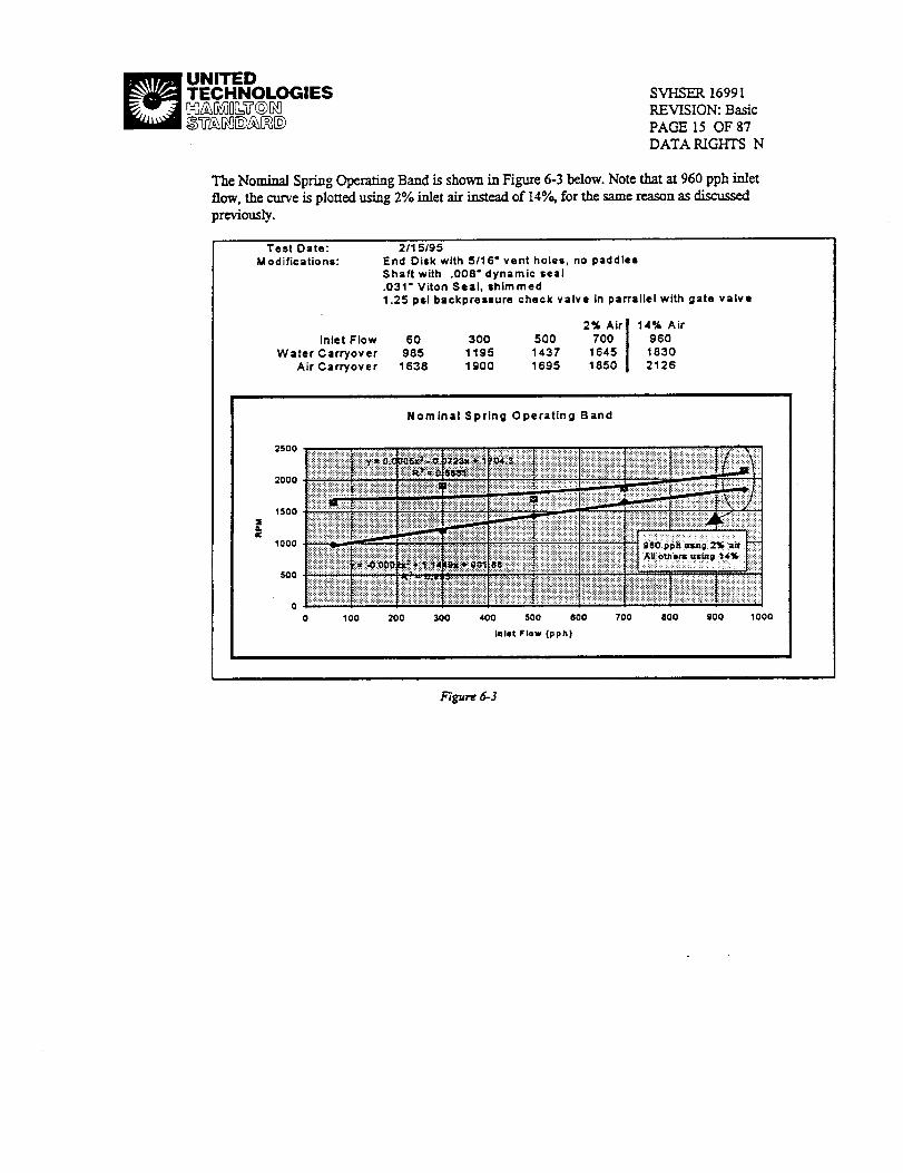
The Nominal Spring Operating Band is shown in Figure 6-3 below. Note that at 960 pph inlet
flow, the curve is plotted using 2% inlet air instead of 14%, for the same reason as discussed
previously.
Test Date:
M odifica tio ns:
Inlet Flow
Water Carryover
Air Carryover
2/1 5195
End Disk with 5116" vent holes, no paddles
Shaft with .008"dynamic seal
.031" Viton Seal, shimmed
1.25 psi batkpreaaure check valve in parrallel with gate valve
2% Airl 14% Air
60 300 500 700 i 960985 1195 1437 1645 1830
1638 1900 1695 1850 2126
r,
2500
2000
15oo
1ooo
500
o
Nominal Spring Operating Band
:.:,:.:,:.:.:.:.:.:.:+:.:.:................:_:H:_:!:_:_:_:_$!:{:!:!:-':" :_:D'_]i_i!!_!i!!!!_i!i_!!i!i!ii_i:.:.:.:.:.:.:.::...:.:...:,.._:_:!8!:_:i:_:i:_:_:_:_:!::::::::::::::::::::::::::::::::
!_i_i_i::_@_!_i_i::::::::::::::::::::::::::::::::::::::::::::::::::::::::::::::::::::::::::................
::::::::::::::::::::::::::::::
::::::::::::::::::::::::::::::::::::::::::..............................,,,.,:.._,...,.....
.:.:.:.:.:+:.:.:.:+:.:.:.:,
::::::::::::::::::::::::::: ......::::::::::::::::::::::::::::::::::::::::::::::::::::::::::_:.:.:.:.:.:.:.:.:.x,:+:,:.i!i:!_i!_!_!i!_i!_:i_i_!":':':':':':':':':':':':':':':'
0 100
iiiiii!iii
iiiiii!iiiI ! ii200 300 400 500
::::::::::::::::::::::::::::::::::::::::::::::::::::::::::i?_::!i:i!iii_iii!!!:i_
.:.:.:x,:.:.:,:.:+:.::..,....,.,...........,...,.,,...,.,..,..,,..,,,..:::::::::::::::::::::::::::::
;!iii!i;iiiiiii!;!!ii!i!iii!i_:::::::::::::::::::::::::::::
i@!iiiiiB@iiiii_iiiiiiiiiiiiiiiiiiiii;i_ii@!!iiiii@
800 700 800 900 1000
Inlet Flow (pph)
a_'3gur_5-3

_ UNITEDTECHNOLOGIES[X]_.,£q08=_@C_
SVHSER 16991REVISION: Basic
PAGE 16 OF 87DATA RIGHTS N
The Maximum SpringOperadagBand isshowninFigure6-4below.Notethatat960pph inlet
flow,thecurveisplottedusing14% airforallinletflowrates.
Test Date:Modifications:
2/15/95End Disk with 5/16" vent holes, no paddlesShaft with .008" dynamic seal.031" Viton Seal, shimmed1.25 psi backpressure check valve in parrallel with gate
Inlet Flow 60Water Carryover 1150
Air Carryover 1935
300 500 700 9601444 1630 1780 19502048 1925 2175 2250
250O
2OOO
1500
RPMooo
,5OO
Maximum Spring Operating Band
......................................................iii ,i ii@@iiii iiiiiii =iiiiiiiiii=:,ii ........................
............... •,..,................... :;::::.:,:::-:.:,: i:i:!:i:_:_:i:i_:i:_:!:_:
!_!_i!!!!_!!i_i_."!i_i!i!ii_:::::::::::::::::::::::::::......................................................!iiii!@i@iii _ _ ..........................._:_i_::::_::_{_:_.............. """""'" :::::::::::::::::::::::::
i_i!!_i_i_i_i_i_i_i_i_i ======================================:::::::::::::::::::::::::::::::::::::::::::::::::::::::: ""' ' '""" ::i:i::iii::ii:_::i!iii::!i!i!il
.............. :::::::::::::::::::::::::
:!@i_i!i!!_!i:i!:!!i::i::iiiii::i:#iiii::iii::i::i::::_:is!,_s!s_s!si:i ..........................i i ======================:!:isis_:!sis_si:!i!i:i_ii!iiii_!_i!:i_!_.........................................s_:_:_s_s_s_s_s::::::_i_!_:!_!_!_:i_!_!_:!_@i_::__i@::;::i@i::i_::: :::::::::::::::::::::::::::::::::::::_:_:::_:S...........................!i!_!!:!_i_i!!_!_!_!!_:i_!Tii!_!i!!!_!!!!:!_i::_ii!_!_!_!i:!_!ii{i_i_:!_i_i!_!::i;!_i_i_!_!_:_i_!_i_i_!_i_i_i_!:::::::::::::::::::::::: ::::::::::::::::::::::::::::::::::::::::::::::::::::!_!_!!!!iii!!i_!!_ii!i_i_i
0 ...... i ........
0 100 200 300 400 500 600 700 800 900 1000
Inlet Flow Coph)
• Water Carryovi
"Air Carryover I
F/gur_ 6-4
Theseresultsimpliedthatanoperatingbandexisted,butthatonecouldnotbefoundtoaccommodatetheend.re60 -960pph rangeofinletflows.Duringameetingheldto
these observations, it was agreed that it would be desirable to flatten and/or lower the watercan'yover ma'vc. If accomplished, this would help to create an operating P,PM band in whichneither water nor air carryoverwould occur for any inlet flow. It was theorized that the first disk(inlet side) in the disk assembly might be too close to the housing, thus restricting water flow atthe higher flow rates. The first disk (that nearest the inlet) was removed and the nominal springperformance map shown in Figure 6-5 was obtained.

UNITEDTECHNOLOGIES SVHSER 16991
REVISION: Basic
PAGE 17 OF 87
DATA RIGHTS N
Test Date:Modifications:
2/I7/95End Diskwith5/16"ventholes,no paddles
Shaftwith .008"dynamicseal.031"VitonSeal,stemmed
1.25psibackpres_Jrecheckvalveinparralle[withgatevane1stDiskNot installed(inletside)
14% AirIrdetRow 60 300 500 700
New Water Carryover 16_ 1750Previous Water Carryover 985 1195 1437 1645
Previous Air Carryover 1638 1900 16_ 1850
2% Air
96O192518302126
NominaJ Spring Operating Band
250O
1 ! I2=o iiiiiiiiiiiiiiiiilliii:iiiiiiiiili:iiiii_=i_i_i_i_i_izi_i_i_i_i_i
" 10C0 :::.:::_T !iiiii_i!i_i!ii_!:!!!:l
0
0 100 _ 300 4_0 500 600 700 800 900 10C0
In_ FZow(p_)
4,Wmr Czn3o_
l_r Carryout
Fi_u_ 6-5
Although the water carryovercurve got worse, itdid sccm to parcel the originalcurve.This
observation suggested thatnot only should the firstdiskbc replaced,but somehow cnhancecL
This conclusion led us toconsider putting an additionalEnd Disk in the firstdisk position It
would, because of itsgeometry, provide both add/aloha]surface area to help rotatethe water ring
further (when compared to originalflatdisk) and provide additionalclearancefzom the housing.
Both featureswere expected to resultin a lowering of the water carryover curve.
ScvcraJ other ideas to improve the MLS performance wcr¢ discussed atthistime. Another idea
relatingto wat_ carryoverwas based on the observation thatas the RPM islowered, the rotating
water ring collapsod onto the disk assembly shaft at the inlet end first, and then progressed
towards the other end. The idea that arose was to move or plug the shaft vent holes nearest the
inlet end in order to delay the onset of water canyovcr.
Itwas alsotheorizedthatan airrestr/ctionmight bc present causing the observed air c_rryovcr.It
was decided to modify a new setof SVSKI20368-1 Disks tochange theirthreevent holes into
vent slots,each extending through ~50 o arc (sccFigure 6-5:SVSKI2086g-I Disks with Vent
Slots).Slotsinsteadof largerholeswere desi.mbl¢as the slotscould increa_ the airflow area
while not moving the vent holes any closerto the air/waterboundary. It_ alsodcc/dcd that

_ UNITEDTECHNOLOGIES SVHSER 16991
REVISION: BasicPAGE 18 OF 87DATA RIGHTS N
theShaft be modified to provide two additional vent holes, making it easier for theairto ventinto theshaft.
Vmt Sio_
Figure 6=6:SWSK120868-1 Disks with Vent SloU
Several iterations of modifications to the MLS and verification tests took place to verify theseideas. In summary, the addition of an End Disk in the firs_ (or second) disk position, the use ofvent slotsinsteadof holes in the _ and the shifting of the shaft's vent holes two disk=positions_ away from the inlet (by using the new four vent-hole shaft with the first two holescovered) presented an improvement to the water carryovercurve, but not to the air carryovercurve, which now had become flatterbut also lower in RPM. These results are summarized inFigure 6-7.

_ UNITEDTECHNOLOGIES SVHSER 16991
REVISION: Basic
PAGE 19 OF 87
DATA RIGHTS N
Test Date:Modifications:
Purpose:
Inlet Row
New Water CarryoverPrevious Water Carryover
Previous Air CarryoverNew Air Carryover
3/2/95
End Disk with 5/16" vent holes, no paddlesShaft with .0(_' dynamic seal.031" V'rton Seal, shimmed
1.25 psi backpres_ure check valve in parrallel with gate valveAll Disks with vent slotsFour Vent-Hole Shaft, 1st Two Holes CoveredEnd Disk In 1st Disk Position, No #2 Flat Disk
Reduce air restriction between disksPrevious data taken Feb 15
14% Air I 2%Air
60 300 500 700 9601052 1207 1358 1482 1643
985 1195 1437 1645 18301638 1900 1E_5 1850 21261573 1579 1738 1736 1838
Not Rotted14% Air
1620
1728
|
25_0
20C0
1500
1000
5OO
Nominal Spdng Operating Band
- ----,z"'-x• NewW==rCmyo_A Pre,rJo_ W:,*erCarr,_wX Prevcu=/WCa_._• Nc,w_Ca'r,/o,_
_ Pmio.=Water
_Pren:x=,_rCaTyo._
Figure 5-7
CONCLUSIONS REACHED AT THAT TEVIE:
• Concerns arose that there might be a water restriction ia the MLS, _y at higher flow rates,
because of the proximity of the first disk to the inlet housing. The use of an End Disk in the first
disk position (that nearest the inlet) was a consequence.
* Concerns arose that there might be an air restriction in the MLS. The flat _ @ere m<xtified to
change the vent holes to dots, and the shaft was modified to add two additional vent holes as a
consequence.
• The observation that the water ring col,lapses onto the shaft at the izdet side first led to the u.s¢ of
the new four-vent-hole shaft, but with the first two vent holes covered (those nearest the inlet

_ UNITED
TECHNOLOGIES SVI-ISER 16991REVISION: Basic
PAGE 20 OF 87DATA RIGHTS N
side). This effectively shifted the shaft's vent hole location two disk "positions" away from theinlet=
• These modifications (i.e.: the inchision of an End Disk in the first or second disk position, the
change to vent slots in the disks, and the shifting of the shaR's vent holes away from the inlet)improved the water carryover performance of the MLS, as evidenced by the lowered RPM values
at which water carryover occtn's for inlet flows of 500 pph and above.
• These modifications had a mixed effect on the air carryover curve in that it was now flatter but
was also lower in RPM than it had been previously, especially at inlet flows of 500 pph and
higher.
6.1.5 TEST PERIOD: Mar 3, 1995 - Mar 12, 1995
SUMMARY:
With the water carryover performance improved, attention focused on air carryover. Theapparent lowering of the air carryover carve was not understood. The decision was made to
quantify the amount of gas present in the water outlet lines (both process line and main outletline). As per the MLS Plan of Te._, the process Line was held at 50 psi downstream of the
process pump, after which it returned to ambient pressure. Air carryover measurements weremade with the process line at 50 psi and at ambient pressure (labeled 0 psi). In addition,measurements were made at 1900 RPM and at 2500 RPM to help document the effect RIM has
on air carryover. The 1900 RPM value is based on the performance mapping using the nomimlspring setting (see Figure 6-3 on page 15); it represents the lowest constant RPM value that will
avoid water carryover for aLl inlet flow rates.
As expected, test data indicated that keeping the process line at ambient pressure resulted in
higher measurable quantities of air at higher flow rates, as the absence of higher pressure did notforcesome percentageofthe air intosolution.All subsequentaircarryovermeasurementswere
made withtheprocesslineatambientpressure,toprovidemore accuratemeasurements andconservativeconclusions.
The effectofRPM on aircarryoverissummaxized inFigure6-8,below.As can be seen,higher
RIMs resultedinhigherpercentagesofairpresentinthewaterlines,cspeciallyathigherflowrates.

_ UNITEDTECHNOLOGIES SVI-ISER 16991
REVISION: Basic
PAGE 21 OF 87
DATA RIGHTS N
ITest Date:
Modfications:
Purpose:
3/8/95
End Disk with 5/16" vent holes, no padd_esShaft wi_ .006- dynamic seal
.031" V'rton Seal, shimmed
1.25 p_ back_'essure check valve in parralld wit_ gate valveAll Disks with vent slots
Four Vent-Hole Shaft, 1st Two Holes Covered
End Disk in 1st Disk Position, No #2 Flat Disk
No Backpressure Regulator Present in Process Line
Measure Air Carryover in Process and Main Water Oulet Lines vs RPM and Inlet FlowConstant: Inlet Air Volumetric Row Rate = 14% of Water Volume_c Flow Rate
Total Air Carryover with 14% Air in Water at inputInlet Row 1900 RPM 2500 RPM
(pph) % Total Air % Total Air60
100 0.020 0. 008300 0. 029 0. 050
500 0. 025 0.038700 0.039 0.105
960 O.042 O.083
0.12
0.10
0.08
0.06
0.04
0.02
0.00
Effect of RPM on Total % Air Carryover
I _nt RPM
""_ X_._
190 RPM
0 100 200 300 400 500 600 7QO 800 900 1000
k_t mow (pph)
F/gure 5-8
The maximum percentage of air allowable in the water carryover had been previously documented to be
0.4%, but this value was based upon the worse value obtained with the pre-development MLS u._itmentioned in Section 3. A review by the HSSSI AaaJysis group established the atlowable percentage of

_ UNITED
TECHNOLOGIES SVHSER 16991
REVISION: Basic
PAGE 22 OF 8"7
DATA RIGHTS N
gas carryover that will go back into solution downstream of the 50 psia process pump to be 4.5% air. Themeasured air carryover was significandy less than this value.
A final observation during this testing was the difficulty in obt_i,l,g repeatable data.
CONCLUSIONS REACHED AT THAT TIME:
• The percentage of air that is carried over into the water outlet lines increases with increasingRPM and inlet flow. Becanse the MLS is designed to be used at a constant RPM, it was
concluded that the RPM chosen needs to be as low as practical (i.e.: the lowest value that willavoid water c_rryover for all flow rates). Based on the performance mapping done with the spring
at the Nomin_ setting, 1900 RPM was chosen as the operating value.
• The air carryover was measurably higher when the process line was not forced to 50 psia, becausethis high pressure forced some percentage of gas into solution. Because the test setup actually
mcasm'ed free gas, air carryover would henceforth be me,asu_ed without the 50 psia segment inthe process line.
• The worse case total percentage of air present at 1900 RPM was 0.083%, when testing wasperformed using clean water. Analysis indicated that a maximum of 4.5% gas carryover would
go back into solution. The actual air carryover was concluded to be at a reasonable level.
Obt_ni,g repeatable air carryover data was di_c_tlt.
6.2 Soap & Water
With the performance of the MLS mapped and an operating RPM chosen, testing of the MLS was begunusing soap and water. Differences in performance were to be documented and compared to those obtained
using clean water. It was expected that the performance of the MLS would be affected by the addition of
soap to the water - of the three water types that would be used during testing (clean water, soap and waterand shower water), the soap and water mixture was expected to result in the highest percentages of aircarryover.
Approximately 30 grams of the soap mixture was added to the 8.5 gallons of water in the test setup.
6.2.1 TEST PERIOD: Mar 13, 1995 - Mar 14, 1995, Water Carryover Performance
SUMMARY:
The water carryover performance using soap and water was mapped, and is summarized in
Figure 6-9. As can be seen, the water carryover curve using soap and water roughly parallels thatfor clean water, but requires 150 - 350 more RPM. Initial stages of carryover typically consisted
of soapy "foam".

' UNITEDTECHNOLOGIES SVHSER 16991
REVISION: Basic
PAGE 23 OF 87
DATA RIGHTS N
lq_r V_-Idnk _IL Is "I_ I_:tcsO_m_
r_d I_ki_ 1._r'h_ Pcl_kn.No#2 F_ r'h_
M_ V_u Ct_O_ inAi-V,_ L__ A_ Vdtmmi: lqc_ R_ = 14%a"_ vat.mini: l:k_ R_
,S_+V_=OcTo_ _ 1330 _ I_ 1"744 l
t
t
12
E
C
i.... _"
//
_._ I*'_ _
_m
0 _ :DO -m 400 ,m m_ _ _ _n ._
_gar¢ 6-9
CONCLUSIONS REACHED AT THAT TIME:
• The change to soap and water required &om 150 - 350 more RPM to prevent water carryover. The
water carryover curve obtained roughly paralleled that made using clean water.
6.2.2 TEST PERIOD: Mar 14, 1995 - Mar 28, 1995, Air Carryover Performance
SUMMAJ_Y:
Began to map the air carryover performance using soap and water. Repeatability of data and
higher than anticipated air carryover results (with total percent air carried as high as 0.9%)

_ UNITEDTECHNOLOGIES SVHSER 16991
REVISION: Basic
PAGE 24 OF 87
DATA RIGHTS N
became themain areasofconcern.Ventingofairwas s011occurringeithercontinuouslyorat
di.scretelimes.Itwas thenobservedthatthecontrolpistondidnotappeartoberespondingtothe
prcssu_changesactingupon itduringventing.Itwas concludedthatthissituationcouldaccount
fortheperformanceseen.Upon disassemblyoftheMLS, itwas foundthatthenutwhich tightens
thecontrolpistondown ontothecontrolassemblyhad loosened,therebyallowingthepistonto
wobbleconsider'ably.Inoperation,thiswould allowthepressuresthatnormallyactupon the
pistontoequalizewithe_ch other,bypassingthepiston.The nutwas tightened,and theair
carD, oves performance again mapped. A "hump" appeared in the air carryover curve, in thatair carryover was elevated in the 150 - 600 pph inlet flow range when compared with the other
values obtained. S¢¢ Figux¢ 6-10.

_ UNITEDTECHNOLOGIES SVHSER 16991
REVISION: BasicPAGE 25 OF 87DATA RIGHTS N
mTest Date:
Moddk:m_or_
Purpo_:
Summ=_.
3t20-28tl_5
End Cia< _ 5/16" vert ho4es, no paO::les
sr_t v_th .008" OF_rn¢ se_
.031" V'lton Seal, I¢_nl"ned
1.25 pc _ ct',eck valve m l:mn'aJ_ wth gate valveAll Dis_ ',_t_ vent slots
Four Vent-Ho_ _ ls¢ T,_o I-k_es Coveted
End E_sk in la Disk Pos_t_'l, No #'2 Rat Disk
Pmce_s L.Jne,,_0 l:_i
Map Corrbned %/_r Carry-OvertaJ¢_ w_ urd in bo_ hortzonal and ver_cal ('inlet down)
Cor_ar¢ lrlet Air VoJ_F3owRat_= 14%dWater Volumetric FlowRa_ 19CORPM
"Bump" in oJrVe for unit in hortzortai po=t_on =t:Utbumd to lg effec= on _ pl_ inlet _ _ _d _
lg e_'ects e_rn_r'_ed I_ tuning unit to vetch.Ro-ctu_x of hodzo¢_ nmJIt= ei_ days lair ¢=_rrm tt_ improve_n_t men in ve_ca_ poBt_n
TotaJ Air Canyover It 1900 RPM and 14%Air at Input
Process I.Jrl (_ O psi. Norm_aJ Spring3rJt_5
Honzor_
Ir_,,t Flcm Clean warm" Soap + Water
(pph I % Total Air % T_I Air60 0.106 0.C_5
100 0.O2O 0.O64
:_0 0.238 0.084
300 0.0:29 0.5_0 0.068
500 0.025 0.4_1 0.0636_0 0.160 0._
700 O.03g 0.C_9 0.041
9_0 O.O,_ 0.0_2 0.043
3/23-27/_5 3r28/95Ve,lX_I 2r, d t-loozorCal
Soap + Wate_ Soap + Water% To_l Air % Total A_r
0.485
0.384
0.(_94
TotaJ % Air Canyov_ I_ 1900 RPM
o=oeu_°°ii_iii:i!i!:!!i_!i!i!i!i!iiiIii!!!i!!i_i!_i_i:_i!i:ii!iIi_ii_i!:_!i!ii_i!:i:_::::_:s_,:_::s_:ss_s_::s:_:_:_s_:_ iiii_!ii!il}ii_!ii_ii_i!iiii[ii_!ii!!!i:_iiiiiii_ii_iiiii:_l::::/:_::_:_:_s_:_s_s_:_:_!ii}:_iiiiiii!_iii!_ii_i-iiiii_i}ii:ii_iiii:iii_ili:_tiiii!i_:_iii}_iiii!i!iiii_!ii;i_ii!_!ii!.i@_!i_i_:_i:._:i!!i!:_ii_:i_i!:i_i_i
a,=,m iiii!iiiiiii!iiiiiiiiii_ili!}iilliiiiii_ili!ii_:iiiilli!_Hiii:!_iiiiiiiii::iii i::iii::iiiil}_;:i!_ii:_i_iii}i_2;i_ii_'!_iiiH@i2i!_iH!i:i!_!i!i!iiii_ii@_2ii£!i_i}!_i!i{i!i!ii_i_i_Ji!iiiiiii!i}_ii!iiiii!!iio.4oo ............... _: :::::::::::::::::::::::........... :::_:__!!:._:.!!!:.;:._:.!:.!_;_!!_;;i!!_!i!;!;_i;!;!:_:;_!ii_;M;!_@!ii!_!_;}:-!:.!_i_:.!i:':'::::::::::::::::::::::::::::::
::::::::::::::::::::::::::: :: ::::::: ::::;:::::::: :::::::::::::;k:. ::{::::::.::::x:::::: :::::::::::: ::::::::::::::::::::::::::
iiii;ii;:i i:, :!::iiiiii;ti:i;;;i;ii;iiiii?;i;;i;;i ;tiiii;;ii;il;i;i;;ii@i;iiiii;iiiiiiiiIii:i;;iii;;iiiiiiiii:liiii;;iiiiiii- - =-,w..,- .,,
= i:;i:@ii,:!.!ii::ii:i,i it
Figur_ 6-I0
Discussions concerning this data led to the conclusion that it was a side-effect of the pre-swirl
chamber. It was believed, and visual observation through the plastic MLS tended to support, that
at low flows (60-100 pph), the water stream merely trickled into the pre-swirl chamber due to itslow inlet velocity. At the high flows (700 -960 pph), the inlet flow swirled entirely around the
perimeter of the pre-swirl chamber due to its high inlet velocity. However, at the intermediateflow ranges, the inlet flow began to travel along the wall of the chamber, but then collapsed due
to gravity, _Jling to the bottom and causing additional aeration of the soap and water solution.As this problem (high air carryover) was not encountered using clean water, it was concluded
that the addition of soap was the enabling factor in causing elevated air carryover. Since a

_ UNITED
TECHNOLOGIES SVI-ISER 16991REVISION: Basic
PAGE 26 OF 87DATA RIGHTS N
redesign of the pre-swirl chamber was impractical within the context of the cuxrent program, itwas decided that the situation could be remedied by designing a disk that would extend into the
pre-swixl chamber from the first disk position. This new disk would help force the inlet streaminto a rotational flow. A new Inlet Disk, SVSK121960-1, was designed to meet these
requirements.
Because the problem with the pre-swirl chamber was essentially a lg effect, it would not be
expected to occur in space, nor would it be expected to occur ffthe MLS were ofiemed vertically.To veri_ this, the MLS was reoriented vertically with the inlet down. The air carryover
performance was again mapped. Referring to Figure 6-10, it can b¢ seen that the "hump"disappears, that the air carryover curve is linear, mad that it is slightly higher than it was withclean water. It was therefore concluded that the =hump" seen was indeed a lg inlet housing
phenomenon.
The pos._'bility existed that the improvement seen in the air carryover was atm"outable to the age
of the soap and water solution (the soap and water solution had been in use for two weeks at thispoint). To verify, the MLS was repositioned in a horizonud orientation and some data points
were obtained. Referring to the points labeled "2rid Horizontal Soap & Water..." in Figure 6-10,it can be seen that the "hump" in the air carryover curve reappears. It was concluded that the
improvement in air carryover seen in the vertical orientation was not atm'butable to an agingeffect of the water.
As has been mentioned previously, it was observed during this portion of testing that the ventingof air would still occur either continuously or discretely, although the discrete mode was observed
as being the predominant one. The ability to obtain repeatable air carryover data was at timesdifficult and a connection between the _te venting and elevated air carryover seemed to exist.These wereareas of concera, but since the overall results were favorable, it was decided to
proceed on to testing with shower water to further assess the effects of different waters onperformance.
CONCLUSIONS REACHED AT THAT TIME:
• The effectiveness of the pre-swirl chamber wus agected by gravity (a I g phenomenon).
• The water and vertical air carryover curves were considered acceptable, and no change to the1900 RPM operating speed of the MLS was considered necessary.
• A new inlet disk (SVSKI21960-1) was designed to correct the lg phenomenon. It would extend
into the pre-swirl chamber and force the in/et stream into rotational flow.• Air venting of the MLS would occur either continuously, or more common/y, at discrete
intervals.
6.3 Shower Water
With the performance of the MLS mapped using soap and water, testing began using collected showerwater, as per the MLS Plan of Test. Until such time that the new SVSK121960-1 Inlet Disk would
become available, air carryover performance was made with the MLS in both the horizontal and inlet-
down vertical positions.

_ UNITED
TECHNOLOGIES SVHSER 16991
REVISION: Basic
PAGE 27 OF 87
DATA RIGHTS N
6.3.1 TEST PERIOD: Mar 29, 1995 - Apr 10, 1995, Air Carryover Performance
SUMMARY:
Began mapping the air canyover performance in the horizontalorientation. Data suggested thatperformance was worsethanithad beenusingsoap and water.The "hump" reappearedasexpected,but
a total air canyover of 1.440% was recorded at 200 pph inlet flow. When the unit was turned to the
vertical (inlet down) orientation, a problem was found with the shaft seal; it was leaking water onto themotor and consequently affecting the RPM control. The motor was removed and cleaned, and testingresumed. Observations indicated that the RPM would s-till flu_mmte with the MLS oriented verlJc_ly. It
was apparent that the RPM fluctuations were directly influenced by the discrete venting cycle.
Since the motor had been repaked, it was decided to re-map the MLS air carryover performance in the
horizontal orientation. The performance was improved. Figure 6-11 shows these results along with theresults obtained with clean water and soap and water for comparison As expected, the magnitude of air
carryover was less using shower water than it was using soap and water. A slight "hump _ was apparent in
the air carryover curve, a.swas seen with soap and water.

_ UNITEDTECHNOLOGIES SVI-ISER 16991
REVISION: BasicPAGE 28 OF 87DATA RIGHTS N
P'uq::os_
4/4/95 - _5,_5
End Disk _ 5/16" veto ho_, no paddes
SPaft ,,,_ .008" d_lmic r,_.031" V'_n Se_ mimmed1_S psJrcx_q::nssum cl_:_ _ in s_rJl_ _*,_ Q_Ix=_/_ C)is_ yam vent s_sFo_Vent-Hole _ 1_ T_to Ho4_
End Dis_ in 1st (:Xr,k Pe=_ No ¢2 Ra¢ DL_Proem= Lm at 0 psi
Map Combned % Air Cany-Ovw. Su_ f_" csean we_'. so_ & rater. _ v,_mrData tak_ ',,_m unit i_ hocizoctta£_ConsKan£ INe(A_r Vo4umetricRowRa_* 14%clFWslm'Vobane_icFlowRat4t, 1900 RPM, NomiraJ ,Sprig SeCbng
Total Ak" Carryover a¢ 1900 RPM and 14%A_r Z Inpu¢
Proem; Line Q 0 psi. Non,We.ad._rlng
In/e( Flow Clan Wa_" Soap + W =*-*
_oh) % Total Air % Tcta! Air
II
4F,_J5
Slx_4." W =*,* I% Total Air I
I
0.116 I
0.023 I0.172
o.112 I0.0800.018 I
0.0100021
m
(;] 0.1C5100 0.020 0.064
200 0.238300 0.029 0.SS0G00 O.025 0.451600 0.160700 0.039 0.0_960 0.042 0 052
Tota_ %A_r ¢atn_r In I._d=_ntal Oden_at_n
I. _na ......................................................
._ !!!!!!!!!!!!!!i!!!!!!!!!!!!!!_i!iii_!iii_i;_i_i_i_i_i_,_ _!i!!iii!!!i!i!i!i!i!i!i!iIi!i!i!i!iiiiiii!)iiiiiiiiiiiii!iiiiiiiiiiiiiiiiitiiiiiii!_iiii_:
ii! ii i:::::::::::::::::::::::::::::_::;i_:/:;i_ii:_iii::_)i::_i_i,:.:.:-:.:-:-::.:.:.:.:.:-:,::':':':':':':':':':'::':'_ ,...........:::::::::::::::::::::::::t:i_!iiiii_i_iEi_ii_!_i_l:i_!E!_ii!!_i!_i_!_!_:
=._m,;":::_-:_ ii::::iiii::_,_==========================================
!i!ii!i!iii!i!iii!i_!iiiii!(iiiiii_iiiiiii!iii!i!iiiiii_!_!i!!!i!i!i!_!i!i!i_i_i!i_i!i!i!i!i!i!iii!i!i!i!i!i!_!i!_!i_i!i!i!_!i_ii!i_i!i_!i!i!i!_i!i!i!i!_!!i!iii!_i_;_i_i_iiiiiiiii!iii_i!_iii!_i_iiiiiiii!i!i!iiiii_i_:_:_:_::_;:_:_:_!i_iiiiiii!iii!_!_ii_iiiiii_!_ii!i!)!i!i!i!i_iii!i!i!i_i!i!i!i!i!i!i!i!iii_i_i!iii_iii!iii_i_ii)ii!!ii!_!i!iiI_!ii!i_i!!!i!_!i!_iiiiii_ii
_i_i_!_i_i_i_i_i_i_i_...........................i_i_i_i_i_i_i_i_i_i_i_i_i_i[i_i_i_i_i_i_i_i_i_i_i_i_i_i[i_i_i_;_i_i_i_i_i___i:i_i_i[i_i_i_i_i_i_i_i_i_i_i_i_i_======================iiiiiiiiiiiiilIiiiiiiiiiiiiiliiiiiiililiii:i
_i!i!iii!i!_i!i!i!i!i!i!i_i!i_i_iiii_i_i_i_!i_i_i!_i_iiiii_ii_iii_i_i!i!i!!!!!_!i!!!i!!!i!i!!!i!i!!!!!_!!!!!!i_i!i!!!i!_!_!_!_!i!i!i!_i!i!_!_!_!_!_!_
In=l 1=1==_1_
Figure 5-11
Ke-mapped the vertical orientation air carryover (inlet down) performazce. Repeatability of datawas again difficult to achieve, and as before the focus was on trying to maintain as constant a
back'pressure as poss_'ble. The idea emerged that the backpressux¢ check valve was sticking.
Impacting the valve sometimes seemed to "correct" this problem. Later observations noted thepresence of severe turbulence within the MLS downstream (from the point of view of the waterrotation) of the main water exit port. Rapid intentional cycling of the solenoid valve seemed to
=correct" this problem. Acceptable data was eventually obtained, and is shown in- Figure 6-12along with similar data for clean water and soap and water. The shower water curve is nearly
identical to the clean water horizontal performance curve.

_ UNITEDTECHNOLOGIES SVHSER 16991
REVISION: BasicPAGE 29 OF 87DATA RIGHTS N
T,,,,d I_IE #6'94 - 4t 1(_1985
Erd Dmk v_ 5'16" _1 holes, no ixmUles
Shd v_h .00r _,_d.031" Vlcn Se_ s_irnnd
t25 _i tx_:n_s_re ,:_s:k v_e in pauid ,,_ _te ,da_e
NI CiS_ v_t,h ',el sk:ts
Four V_t4-ble Shall,IslTwo Hdes O_s_d
End _sk i_ I_ Ci_k I_ ND _ R_ D_k
Map _ % _r C_y-O_. Surnna_e br dem w_er. stop & _', sh=_r wZer
DIa t;d_n w_h unl _nVer_ cmrtaltion
Q:nm_ Ir._ Air VdurTm_ RON Ram - 14% or Wala" Vdu1"eb_ Ro_ Rale, "_00 RRvl, NuTir_ Spdr_ SallJng
Tol_ Air _ :,* I_'_n RPM and 1_%J_Ir ,11Lr'_:u_
_roomL_ _ 0_, Nurr_mJSp_ng
Inl_ RoN QemW_f Soap+ V_r _V_a
¢¢t_ % To_al Ar % T,_ Ai¢ % T_ta Air
_ -Jn"l
0.18) I
GI m I
Gla0 I
G12) I
T4=_al%Air Candour In Vertk:d Qlerll;d_n
_cr_ _ vv_
Jo - . tJ_ O-_orm _aw_a_
Figure 6-I2

_ UNITEDTECHNOLOGIES SVHSER 16991
REVISION: Basic
PAGE 30 OF 87
DATA RIGHTS N
CONCLUSIONS REACI_D AT THAT TIME:
• The horizontal orientation air carryover performance using shower water was simJla.r to thatobtained using soap and water in that a "hump" appeared in 200 - 500 pph inlet flow range. The
overall magnitude of air carryover was less than it was with soap and water.
The vertical orientation air carryover performance using shower water was similar to that using
clean water in a horizontal orientation. Repeatability and point-to-point variation of datacontinued to be areas of concern. Focus was again on trying to maintain as constant backpressure
as possible., as it was believed that doing so would improve performance and repeatability.
• M_int_inlng a constant back-pressure was anticipated to result in improved performance.
• Variations in RPM occurred when the MLS was oriented vertically, and were directly influenced
by the discrete venting cycle.
6.3.2 TEST PERIOD: Apr 12, 1995 - Apr 13, 1995, Water Carryover Performance
SUMMARY:
The water carryover performance using shower water was mapped, and is summarized in Figure6-13. As can be seen, the water carryover curve using shower water is nearly identical to thatclean water.

_ UNITEDTECHNOLOGIES SVI-LSER 16991
REVISION: Basic
PAGE 31 OF 87
DATA RIGHTS N
Test Dam: 4/12 - 13,,'19_6
Mcx:lif'zcst_on¢ En¢l Dis,k ",_r.,_ 5rl 6" v enz _ no _=ddes
SZ'mtt wcgt .C08" dynam/c r,,u_
.031" Y'i'_Z_n,,Sea,L r,_irnmed
1.25 psi I=_-m'_re ¢a_tcX va/vt in parralJel _h _ valve
A_ Dis_. ",_it_ v qmt s_<Xz
Foul Vent-Ho_ Sha_ lstT_ I-k=4es Covered
End D_d_ _ 1st _ F_i_, No #'2 Rat [:Xsk
I,d..at_ Water Carz'y..Ovw in _ V_.'t
Constant: In_t A/r V(:Jume_'_ Fksw Rate = 14% _ W;mw V_ Flow Rate. I.,IomJnal Spring _
_ W;zta¢ 11g_3 11_ 1340 1418 1 _T_,,_ 168,4
S_I= "' Watt' 1:_, 1:3_0 1370 I_0 1744 1975
C_ean Water 1052 1207 1358 1482 I_'0
14_mlnatSt)rlmgwau_rCaz'_vet S_amnazy
Figure 5-13
CONCLUSIONS REACteD AT THAT TIME:
• The change to shower water from clean water required from 60 - 150 additional RPM to
prevent water carryover
• The water and air carryover performance obtained using shower water required no change to
the previously selected1900 RPM operating speecL
6.3.3 TEST PERIOD: Apr 17, 1995 - Apr 28, 1995, Testing Using P/NSVSK121960-1 Inlet Disk
SUM3tA_Y:
The newly designed SVSK121960-1 Inlet Disk was evaluated_ Th_ disk was designed to correct
the lg effect seen in horizontal orientation air carryover using soap and water and shower w_ter.

_ UNITEDTECHNOLOGIES SVHSER 16991
REVISION: Basic
PAGE 32 OF 87
DATA RIGHTS N
The nc_v inlet disk was insmUed in the first disk position (closest to the inlet), and the 2rid fiat
disk was reinstalled (which had not been present when the End Disk was in.s'tailed in the first
positioa, due to interference).
To vm'if-y the performance improvement e,xpected, soap and water was used, as the highest
amounts of aircarryover were demonsWatcd to occur with this water type. The water and air
carryover performance in both tim horizontal and vertical orientations was rrmpped, and the
_sults arc summarized in Figu_ 6-14 and Figure 6-15.
R_E
V_fyNBN_ C_k_JO_S P_k_m__ vw_ c_yo_ "__,wt um _ so_ &v4_¢
P_x_ t_aT_ _1_14¢35
E_ec_olN_v_k_[_s_
RFMat W'k:_W_r Cam/oarOoanNadra Spma ",e/._ at tr_ S:_ &CU_
k-t_R<_ _0 10) ZX) 300 _ 700N_ lr'_ l:7_ 1"_3 1,40@ 1,457 17"i0 _ 1_1
r_i_o_jur-a_ _ 1200 1370 16_ 1744
|w
:_t._(_t_t_¢ J
Figure 6-14

' UNITEDTECHNOLOGIES SVI-LSER 16991
REVISION: Basic
PAGE 33 OF 87DATA RIGHTS N
P_po_
RiifeclM_ce:
4/21-27119S_
End Cit,,k'*,ith 5/16" '_mt ho_,, no I:_aCdl4_S_ft v,im .0Cg" dynan_ .,_.O31" V',=c_ Se_ r_
1.25 i:_ I:lckCru_Q ct_,ck '.'-_ m mrraL_¢ ,,_<h_ml vaJvo.,M C_ ,*_1_veto slo_Four V_-4-k_ _ Ist Two _ Covem:lNew P_ SVSXI21S¢0-t laJet Disk. F_li Disk In No 2 PosJUoa
Pmoms l.ine m 0 I:i
Verify New In_i: _ Iml_'ovm Ptxfci'mar_Map Oxnl:med Air Canyov_x- in Wam_ l._ms umng So_p & Watw, _ & Vw't_aJ l:_e_ons
Inl_ A_rVo_'1_z_c F'iowR411 = 14% of Wa_m'V."_u.'n_r_ Flow R;I_I, Nomiml _oring S4_t_, 19(:0
Prk:_ Configur'at_on HonzontaJ _ma TaJ_m 3r20-_C,_figu_on Ver_cal _ Ta_n 3/23-27/95
Tom4 ._ir Canyov_ z 1SO0 RPM and 14% Abra_ mpu_
Pmc_zs Line _ 0 psi? Nor_nJ Spdn 9
Nmv Irdet CisJ¢t,Mw Inl_ CLs_ Pm'vk_s_ YectJcaJ Ve_ca_
Ininl lqow 019 ÷ WaCe ,SOlo + W_er Soap ÷ W_ Soap + W_e:
_ph) % Total Air % Total _ % Total Air % To_l Air60 0.105 0,090 0,100 0. r'_
100 0,064 0.347 0.202200 0.238 0, 521 0,170 0, 087300 0.590 0.413 0.164 0.068
500 0.451 0.161 0.031 0.063600 0.160 0,149 0.075 0,033
700 0,0_ 0.104 0,010 0.0418OO 0,O'/7 0.03196O O.O52 0.0a6 0.0_
of New Inlet
on Total % Air Can_v_r
/--'. -- Prm4ous Confi_ra_:n _zon_a;
,S<_p & Wal:_r
..,,._,---New In_et DL_ l-4orizo_a_ Soap &Wamx"
_New Inlet DisX VerOc_ Soa_ & Wa'_
_I=_ Co_,gunmon v_ ,Soa_& Water
Fi gur_ 6-15

_ UNITEDTECHNOLOGIES SVI-ISER 16991
REVISION: Basic
PAGE 34 OF 87DATA RIGHTS N
The addition of the new inlet disk was judged to have no effect on water carryover performance.
As can be seen in Figure 6-15, the new inlet disk did not eliminate the "hump" in the horizontal
orientation air carryover carve, which was not expected. Furthermore, it appeared as if the
"hump _ in the curve shifted towards the lower RPMs, with the maximum carryover now_g at 200 pph inlet flow versus the previous maximum at - 350 pph. When oriented in thevertical orientation, the air carryover performance did not approach the performance of the
previous configuration; elevated percentages of air carryover were evident in the 100 - 300 pphinlet flow range were present. Ob_g good air carryover measurements (in both odentatious)
was againdi_cult,ashasbeen previouslydiscussed.
The solenoidvalvefailedtoa closedpositionwhilemeasuringaircarryoveratthelastdatapoint
(960pph),and consequentlyno valueisplotted.
CONCLUSIONS REACHIID AT THAT TIME:• The addition of the new P/N SVSKI21960-1 Inlet Disk did not affect the water carryover
performance of the MLS when tested using soap and water.
• The new P/N SVSK121960-I Inlet Disk did not ellmin_te the "hump" in the horizontal air
carryoverperformance map.
6.4 Extended Performance Testing
As originallyde.finedtheinMLS PlanofTest,an ExtendedPerformanceTestwould be conductedon a
secondMLS unitasthelastpartoftestingunder thisprogram.The primarypurposeofthistestwould be
to gather experience on how the MLS works in near-continuous longer-term operation using "real"water.
All parties agreed that it would be advantageous to begin the Extended Performance Testing as soon aswas practical - it was agreed that a second rig would be set-up to allow further developmental testing tooccur in parallel with the Extended Performance Testing. It was further agreed that shower water would
be used to conduct this testing.
To better reflect these ideas on how the Extended Performance Test should proceed, a supplementary MLS
Extended Performance Test Plan was developed (see Appendix fit_. MI.,S Extended Performance Test
Plan on page 74). The primary objective of this test would be to document the affect extended durationoperation using shower water has on the reliability and operation of the MLS. To help quantify any
changes, the metal MLS unit was to be performance mapped before and after the extended performance
portion of the test.
As descn'bed, a second metal MLS unit was manufactured and assembled for testing. A summary of this
phase of testing follows:
6.4.1 TEST PERIOD: May 1, 1995 - May 9, 1995, Metal MLS Clean Water
Performance
SUMMARY:
The Metal MLS was fitted with a disk assembly that did not use the new P/N SVSKI21960-1
Inlet Disk. The first disk position was occupied by an End Disk, as was previously done with the
plasticunit.The controlpistonassembly(includingthediaphragm sealand itsshims)from the
plasticMI,S was alsoused.Measurements indicatedthatno change tothesealshims were
require& Severalattemptswere made toassembleboththeinlethousingand main housing

_ UNITEDTECHNOLOGIES SVHSER 16991
REVISION: BasicPAGE 35 OF 87DATA RIGHTS N
together - most a_empts resulted in broken beatings and damaged seals. Rather than delay theinitiation of the Extended Performance Test any further, it was decided that it would beacceptable to use the plastic inlet housing with the metal main housing, as these partsmated.
Once assembled, the water and air carryover performance were mapped using clean water. As
can be seen in Figure 6-16, the water carryover performance between the plastic and metal MLS
units is nearly identical. An observation during this period of testing was that slight amounts of
water would "spit" out of the air vent line whenever the RPM was lowered. This was attn'but_ to
problem with the plastic washer seal at the end of the shaR, and was not considered serious. The
use of the plastic washer was only meant as an expedient fix to the water leakage problem
discussed in Section 6.1.3.
Tes_ 55._1_5M:dr-_om 5"dOs'c_ 5'16"_,t h_ mpsCbs
.031" Vain Sml, d'_rr_
,ql [_ksw_,art dds
Four Ve'tJ-lde Sh_ 1_ T,.m I-bes Covmad
I:_ _'_ V_ C_o_ I_ "rd_m Mm_ 2
Figure 6-16

_ UNITEDTECHNOLOGIES SVHSER 16991
REVISION: Basic
PAGE 36 OF 87DATA RIGHTS N
The horizontal orientation air carryover performance using clean water was mapped, and theresults are shown in Figure 6-17. Note that the Metal unit's air carryover performance is
markedly improved versus the plastic unit's. No air carryover was frexluenfly recorded.Observation during these tests noted that virtually no bubbles were seen in the water outlet lines.Recall that it was the observation of such bubbles in the process line when testing the plastic unitthat led to the premature conclusion that the air carryover seen was unacceptable. No explanation
could be provided for this change, although it does suggest that theMLS has theabilityto
remove nearly all fr_ gas from theinlet water stream under similar conditions.

_ UNITEDTECHNOLOGIES SVHSER 16991
REVISION: Basic
PAGE 3"7 OF 8"7
DATA RIGHTS N
P,nx_
F:_dOsk_h,5'16' _ertPdeS nopaddesS_t_th £05"@raTiCSm.CBI"V_n Sin. d'_m'B:l
AIl:]_ks_h_ertskis
Fo.r_/a-tJrldeShaft,IstT_ H:lesC_dErd13skinl_tnskl:_cr_l_b_ RaHlsk
__ _I_ Ptu3rg
Ra_ L_ _ I'_ Tak_ Mard_8
RaslicUrit IV_al_'it
IdetRoN a_'W_al_ aemV_"
_:_ %Tdd _ %Tc_ At.63 QC[2
1(_ O.C_O QCOl303 QQ29 0£035:0 Qa25 QC[_?CO O.CE]g 0033_EO QO<2 QQ_0
Total"/,,AirCm'yo_
oo_ Melalvs Ras_ MLSUrn.
o_ I _,.L. • )
"i' "
Ra;I¢ Lht I-icr_:_a Qm._ WaW %Tcla[_
M_ Ll'it Fo'imr'la (3m.-=V',las"%
Tc=l ,_"
• - - _.F_=Ur_H=mta_=,_Wtw %Tc;fa Ar)
%T<:_ AH
Figure 6-I7

_ UNITED
TECHNOLOGIES SVI-LSER 16991
REVISION: Basic
PAGE 38 OF 87
DATA RIGHTS N
CONCLUSIONS REACHED AT THAT TIME:
• When tested using clean water, the metal MLS unit was identical to the plastic one in terms
of water carryover performance, and was superior in terms of horizontal air carryover
performance.
* No measurable air was present in the water outlet lines for several data points. It was notknown why the air carryover performance was so improved, although these results suggestthat the MLS has the ability to remove nearly all free gas from the inlet water stream undersimilarconditions.
6.4.2 TEST PERIOD: May 12, 1995- May 14, 1995, Backpressure Valve
SUMMARY:
A new Back_ressure Valve Assembly, P/N SVSK121970-1, had been designed to better regulatethe backpressure. Its intended purpose was to maintain a constant backpressure regardless of the
inlet flow rate, thus e)iminating the need to use the check valve in parallel with the gate valve.Better regulation of backpressure was expected to result in improved air carryover performance.The new valve was designed with the ability to vary the height of a spring, thereby allowing the
de_d amount ofback-pressuretobeset.
The new backpressure valve was installed in place of the previously used valves, and cah'brationrtms were made with 60 pph inlet flow and various spring height settings. Using the lowest
spring setting obtainable, the back'pressure was 1.125 psi. When the inlet flow was increased to
700 pph, the back-pressure increased to 2.6 psi.
A complete map ofbackpressure versus inlet flow was then made at this spring setting, and theresults clearly showed that the backpressure was a function of the inlet flow - an undesirable
_ult To document how the valve body without its pressure regulating components responded tothe inlet flow, the P/N SVSK121973-1 Valve Poppet was removed fa'om the back'pressure
assembly, and a similar back'pressure versus inlet flow map made. The results clearly showed thatthe valve body itself was conm'buting to the backpressure, and implied that the diameter of theoutlet line needed to be increased. These results are summa_rized in Figure 6-18.

_ UNITEDTECHNOLOGIES SVHSER 16991
REVISION: Basic
PAGE 39 OF 87
DATA RIGHTS N
Backpressum vs Inlet Flow
w_ _p=ty = ..,3E.4l__ * 0,0_ -0.0474
I_ =o.gg03
- - - w_par_x_ Wil_oui Po_
y = g_.O7x_ * 0.000_ _ 0.I048
I_ - O.gg74
Figure 6-18
CONCLUSIONS REACHED AT THAT TIME:
• The new backpressure valve did not provide a constant backpressure that was independent of
inlet flow.
• The diameter of the main water outlet line may need to be increased.
6.4.3 TEST PERIOD: May 15, 1995 - May 17, 1995, Metal MLS Water Carryover
Performance in Shower Water
SUMMARY:
The new Backpressu_ Regulating Assembly was removed and the previously used gate valve in
parallelwith the check valve assembly was reinstalled.
The test rig was filled with shower water to map the performance of the metal lvfLS unit prior to
the Extended Performance portion of the test. A similar map would be made at the conclusion of
that test, and a comparison between the two would help to document any performance changes.
Water carryover performance was mapped, and the results are shown in Figure 6-19. As can be
seen, water carryover performance was e_endally unchanged.

_ UNITEDTECHNOLOGIES_L£_rlBT@_
SVHSER 16991REVISION: Basic
PAGE 40 OF 87DATA RIGHTS N
Tmr_
Nmm_im'Em
! ==1 ..-_.-_._.r
m_
m u i
F'igur¢ 6-19
CONCLUSIONS REACHED AT THAT TIME:
• Water carryover performance of the metal MLS unit using either clean water or shower
water was essentially unchanged from the results obtained using the plastic MLS unit withwaters.
6.4.4 TEST PERIOD: May 18, 1995 - June 6, 1995, Metal MILS Air CarryoverPerformance in Shower Water
SUMMARY:
Mapping of the air carryover performance in the horizontal orientation indicated excessive air
carryover. An observation was that the gas venting was exclusively occurring in discrete intervalsduring this portion of testing (with the side effect of having the backpress_e momentarily drop to
nearly 0 psi at each venting cycle) - again indicating that unstable hack'pressure and poor air
carryover performance are related.

_ UNITEDTECHNOLOGIES SVHSER 16991
REVISION: Basic
PAGE 41 OF 8"7
DATA RIGHTS N
When testing began with the unit in the vertical (inlet down) orientation, the operation of theMLS became very difficult in that the MLS would frequently get into an operating mode in which
the air carryover performance was significantly impacted. Repeated attempts were frequentlynecessary to get and keep the unit into a "stable" operating environment.
It was decided to remove the check valve and r_lace it with the new SVSKI21970-1
Back'pressure Valve Assembly. It was hoped that this new valve, when used in parallel with thegate valve to regulate back'pressure, would better regulate the backp_. Figure 6-20 shows
this new setup schematically.
i
I II New Backpresaa'eI Valve _bly
Gate Valve
Water
Out
Figu_ 6-20: New Back-pressum Valve in Parallel with Gate Valve
After installation, test results and observations indicated that venting still occurred in discrete
intervals, with no discerm'ble difference in air carryover noted. This result was observed with the
gate valve open or totally closed. Horizontal air carryover performance was as high as 1.4%,These results are seen in Figure 6-21.

_ UNITEDTECHNOLOGIES
_©_©
SVI--T.S:ER16991
R.EVISION: Basic
PAGE 42 OF 87
DATA R.IGHTS N
Rli_,mnl.ICOC
5'18-_F='ldOsk,,_'_5'16"verthd,es,no]:xaddles
J031"V,_n5_1, stWn'n_1.25 i_ bm_0rmsuB d'md( valve in I:ana_ '_h _ v"Jve
MI Osls_'l vet dols
Four Ve_4-ble SlWt, It Two I-Ues Cove_
End Ci_ in la Os_ l:_i_o_ No _ Rat r1_
_l.im_01i
Very _l_l UrnsP_on'ra_ 5/_ ToI='_sScUn]Map_ _r Ca_o_ _.r_ S_v_r W_rO:nCa¢ Lrd__r",,/dun'a_cRowRa_,, 14%or_,er _ Ro,vl_fa,Nomin_Spr_ _ I_0 RI::_4
I:_fJcUr_Ha'bo'tal_ _o,_a"V_mrI:_ TalenAt0n]5
l:_la_icl.,Inil Mel_iUnil lVlemlUr_l.'h'tz0n_ _ 1,_rtic_
Icd_F1o# St'o_rV_ter _"oA_Wa_er S_o,_rV_m_
_oh) %T,'_/_i' %TcmlN,r %T,:_ .Nr60 0.116 0.154 O.Q20
100 0.023 1.455 0.625
200 0.172 1.184
0.112 0.7'14 0.247
500 0.0B0 0.4107 0.174
600 0.018 0.316 0.049
702 0,010 0.057 0.086
_O 0.£R1 0.029 0.050
%::::::::%::::::::
'L4_I ::::::::::::::.':::
%::::::::
:.:.>:<,t(_ '!!:!!
%:::::::::...................
,., ::::::::::
>x.>>i!ili!i!i!i::%:::::::_!!!!!!!!f:
OlO:l _@!i!!
:::::::::::0.4_r ":;::
_!!!i!iii!i::;:::::::::::::::::::
0._00 x,>x.:
0
_,_:,:.:.:.:.:,:-:.:.:.:.:.:.:.:.::::%:::::::::::.........
..................................::::::::::::::::::::..................- i; i ..............
:.:.:.:.:.:+:. :::::::::;:::::.:
;:;;:::'" ;:::;:;:;: :::::::::::::::!'!!'!'_'!_'i]..........-.. L.>:<.:.:.:.:.:............... ,.:.............
"''":" :::_:::::::::::!i_!!_!'!i_ i!i_!_!]:i!_!!_!::i!i!::::_ili:-.!.:-_-_._.:.................................:.x.:.:.::.:.: ...... :.:-:.x.:-:.:. ;.::.:.:.:.:.:.:$!:18_:i:_:f:_@!_K:X: :::::::::::::::::::::::::::::::::::!:i_i_ii::_i::ii_@:_:_ iiiiii!::!::i::!ii:::.::ff:!]!ii_!i::
::5:::::::::::::i:i:i:i:i:i:i:i:ij. I::::::::::::::;:::::::::::::::::
@::!!!:_:_::w_Niiiii::i1:...........i_!_i_i:#:::
i::!i!::i!@..........!i!i!i!!i}iFi!
T_al %Nr Can_o,_"v.4thShov_"'Nal_"Me_l _ Ras_ MI.S Urns
:::::::::::::::::::::::::::::::::::::::::::::::::::::::::::;::::::::::::::::2:::::::::::::::::::::::::2:::::::::::....,..,..., ..:.........................:::::::::::::::::::::::::::::::::::::%:::::::::::::::::::::::::::::::::::::::::::
.:.:.:.:.:.:.:.::.:.:.:.:.:.:.:.:.:.:.:.:.:.:+:.:.:.:.:.:.:.:.::::::::::::::::::::::::::::::::::::::::::::::::::::ii_i_i_!i_i]!!i_i_i_i!ili_i_!_il:_:!r!:[:_:!:_:!:_!]!il]!_i !ii_ili_i_i!!_i_i::::::::::::::::::::::::::::::::::::::::::::::::::::!:!:i:i:::!:!:!:!:f!'::!:!:!:!: !:!:::!:!:!:!:!:i::::::::::::::::::::::::::::::::
>>:,x,x.x .:,>>:,:<,>: ,.,, ..............
!i!iii!iiiiii_!i!_iiM2i!!!i!!i!i!i@i!_!i!iii_iii?!iiiiiiiiiii_iiiiii_iiii!_
:_:_;i:_:_:_:_:_:!:i:i:!:!$!:!:ii:!SiSi:i:_:i:i:iS]:_:!:!:_:i:i:i:_:f:!:!:!:!::::::::::::::::::.:.:.x.:.:.:.: :::;:::::::::::::::::::::::::::::::.'.'.'.'.'.'.'."
::.:.:.::.:: y".".. .::.:.:.:.::: ::::::::::::::: :::::::::::::::......... :.:.:.::.:::.: ............:. ::::.:::::::::::;:::.::::::::::::::
iii!i!i!i! ii!i!i!i!i!ii!i!i!!iii:!!iiiiiiiii!i!i!i!!!i!i!ii!iiii!iiiii!i!iiiii!i!!ii................................iiiiiii@iii!i!iiiii!i!i!................._iii_::i_II;BI.................................._...............s!:::::.:.r.:.:-:-:.'._. • :_:_::8::_:!:_;'_:':':':':':':
:.::.:,:;:.:.:__.:;_.:.:.:.:.:;::::::::::::::::: :.:+:+:.:.: .:.:+:.::.:.:<:+:.:.>:::.
.:.::.:iU.::..................,.................................::.'.:.:: ,.,., . "
Tcml ,¢(r
,,_II,_. I/_i _iII i._ta_il _'1o_r WlI" % T..',-I
Figum 6.-21
Discu_ons concerning these results were held. To reiterate, the general observadon was that the
air primarily vented at discrete times, rather than continuously. The back-pressure would
momentarily go to 0 psi when venting occurred, and the depth of the water ring would increa_

_ UNITEDTECHNOLOGIES_A_B,7@_
SVHSER 16991
REVISION: Basic
PAGE 43 OF 87
DATA RIGHTS N
asthegaswas vented.The RPM would consequentlychange inresponsetothechangingdepthof
the water ring. It was felt that the interaction of each of these responses resulted in the relativeinstabilitysccnintheoperationoftheMLS unit, and thatthisinstabilityafl'cctedaircarryover
performance.Severalsuggestionsemerged.The firstcenteredon thefactthatthemotorRPM
was afl'cctedby thechangingwaterringdcptltscausedby thedi.screteventingcycle.The varying
RPM would affectthepressuresactingupon thecontrolpiston,which inturncontrolledthe
ventingprocess.Inactualapplication,themotor speedwould be constant.Itwould thereforebc
desirabletousea synchronousmotorduringtestingthatwould bc abletoholda constantRPM
regardlessoftheloadapplied;budgetaryand timeconstraintspreventedany furtheractionon
thisprogram.
A secondsuggestionaroseovertheshapeoftheaircarryovercurves.ReferringtoFigu_ 6-2I,it
can bc seenthatthehighestamounts ofaircarryoveroccurredwith 100 pph inletflow,butwere
atorneartheirlowestvaluesat60 pph.Thiswas trueforboththehorizontaland vertical
orientations.Suspicionswcm raisedoverthisobservation,bccansca difl'crentpump was usedto
producethe60 pph flowthanfortheothers.Water flowrateswere regulatedby two bypass
valves,one placedbeforethe pump and one after.The ideaemerged thattoomuch bypasswas
beingused toestablisha low flowcondition(i.e.I00 pph) witha pump sizedtoproduceup to
960 pph,and thatthepump mightbe cavitating:.Itwas decidedtoregulateflowbyusingvariable
pump speedinsteadofbypass and seeifthatchange made an improvement.A variableAC
transformer(VariAC) was thenattachedm thepump power line,and thebypassvalveswere
closed.
A thirdsuggestionwas thatsomethinghad changedwithinthemetalMLS tocauseitspoor
shower water performance, and that it should be disassembled and inspected.
Testing resumed to address the second suggestion. Using a VariAC to regulate flow and the newbackpressure rdief valve in parallel with a gate valve to regulate backpressure, some performance
pointswere takeninboth thehorizontaland verticalorientations.The majority,thoughnotaft,
ofthesepointsshowed improved aircarryover.To furtherassesstheperformanceofthemetal
unit,aperformanocgraph was made showingthebestvaluesyetobtainedforeach inletflow,and
isshown in Figure6-22.

_ UNITEDTECHNOLOGIES SVHSER 16991
REVISION: BasicPAGE 44 OF 87
DATA RIGHTS N
t,umo_
R_IBf_IK
_'18-24_J6
End[:_sk_ 5_16"_ert hoes nol:_UmSt-ett_ .OCt"_yr'emc s_l.mg'_ton Sere ,.r_m'rt_AI Oit_) ,.l_h ,,err _
Four Vert-Ht:m_ 1st T,_o _ CoatredEn_ I_ inI._EIs4P_m_ No #2F_IO_k
Prc_e_ Une a_0 I_Me_ MBn Ftotirg_:_as_ InletI-bLmrgNew _=ure Rdd Va_ rn iwra_ _U_ _am _e
F_w n,_a=d ey Pwre _ (No sy_)
Verity Mel_ Lira= Pe_f,om'B'_eBy_ ToP'e_c Ur'_Map_ _ Carryo.e"L._ Sho_="W=er
C.,waa¢ IrmtAir Vcdurr_ncRo. Ram = 14% ofWamr _ RowRale, NcmrBI Sl:xtr_Sellir_ I_G0 RPM
Ra_c t.rlt Hom,w_ _ _:_er Wa_" Oma Tamn .=¢l_5Pta=_ Ur_ Vedk_ CriertamnSPo.u="Wa_r Ceta Tal4mAl:_ 6-10
•rot=_. ¢=-_w_ =¢lsoo_ andt,¢_Air= t'eu¢
P_=i¢Unit lUnJt
Honzon_
ll_etF'I_ _l'o/,er Wa_ Shoe_ V_tla"
EO 0.116 0.154100 0._23 0.8_'20O (1172 (1901
0.112 0.7145(;0 0.080 0.3_
60:) 0.018 0.3"167C0 0.010 0.057960 0.CZ21 00_
Rasl¢ Lr_ MelalUr'rt
vesta (InletDo_ Ver_c_(fret
_how_m"WaW _Wa_r% Tc_ Air % Tc_ Air
0.022 0.C_0O.0O7 0.34'10.043 0.3010.053 0.159(1014 0.174
(1000 0.¢,49o._ (10860049 0.(3_
M=l:i vs P'mstlcMLS Urdts
J , ,; , '=-: -1 - "-i-
t_lt Row(.e_
Figure 6-22
It was not understood why the horizontal air carryover performance for the metal unit was sodifferent than it was for the plastic unit, or even why it was so d/ffcrent from that obtain¢<l using
clean water. The test rig was emptied and filled with clean water to repeat the horizontal air

_ UNITEDTECHNOLOGIES SVI-ISER 16991
REVISION: Basic
PAGE 45 OF $7
DATA RIGHTS N
carryovermap. The results('labeled5/25/95on thechartbelow)didnot resembletheoriginal
ones.Itwas concludedthatsomethingwithinthe MLS had changed.
The metalMLS was disassembledand inspected,and theonlydiscrepanciesnotedwas thatone
oftheplasticringsusedtoshim theO1:)ofthediaphragm sealhad been damaged, thatthe
SVSKI20993-1 springadjusterwas notcompletelyseatedintheMLS housingbecauseitwas too
tighta fit,and thattheSVSKI20985-1 Antiromionpin (item# 50 on theMLS assembly
drawing)neededminor stz_ghtcning.The springadjusterwas removed and replacedwiththe
one used intheplasticMLS, thedamaged shim replacedand thepinstraightened.The metal
MLS unitwas reassemble/i,and anothercleanwateraircarryoverperformancemap made
(labeled5/30/95on thechartbelow).Although itdidnottotallyduplicatetheoriginaI,itwas
markedlyimproved (andlessthantlmvaluesobtainedwiththeplasticunit)and concludedtobe
acc_tablc.These resultsaxesummaxized inFigure6-23.
Te.M Dam:
kloamcall or_
5,'30-31/96
End D(ek _ 5/lr _,_ h_ rio
Sl_afl Wlh .00r dynamO*
,031" Vllnn S40¢ mlmmed
AJI Oim v41h _mlt/ale
Faur VeV-4-km _ 1,* _ _ Cavered
En4 04t m let C_a lsoeilJan. No IIQ Irlm O_1(
_ Une d0 _d
New lackprm/t -se/Vadvl In pe_rdd wlLh IJe m
Flow ¢_,lrok4 by Verlm_e Pump q.peed
hpeat C_ln Wabr _r Can7 mw abr Sho,_r Waler "reJn9
V4rffy Idelal t,k_'s Show_ Wmw Pork_mmnce is Nat Am_b_a_ to _
Wmer and Com_0_ned Air Carryo.,qr Uedng _,een Warn,
C_nI_-V: hVet ,_r VW Flow Rale _ 14% c_ W met Vc_*amWlc Fk_w Raui. hk_mal ,S_la.0 ,Sting. 1_ RP_I
P'odc Un4 Ho,_nml _mm T_mn Mar¢_ 1
Ta_al AM Cel"yo,_w _ 1904 ItPM and 14% A_r _
Proe_e I.Ine 4D 0 pa, Nominal Sp*V41
_96 _ SrJ_ 31_a5
Pteak Urdl Melm Ue_ k4_ Un_ k4em_ UrW
_rt_on_ I.l_Lt anm_ Har_aneml Hor_onmJ
kMM Flow C_n WW _a_ Wml_" C"_*,m wamr C'_l*'_ Wam¢
U_h) % 'T_m A4r _ To4a_A,Ir _ Tm A,Ir % T_AJr
el0 0. N'_
100 O.O20 0.00'1 0.O73 0.010
300 0. ,'Y'_a 0.000 0.0_ 0.022
0.Q_S 0.000 0.080 0.0'12
700 0.0:_ 0.0_ 0.0_ 0._,,_
_0 0¸042 0.0_ 00_1 0001
Metad Un_ Clean Wa_er Ale CurTyove¢
Nemmvld 811r_ t4% air / IlVm_ 1111_0IUUqA
\
\...... _:'"1
...:_ ....22;-I ..
• • * .... v_ 0 *,<
m_4 n,_ u_ noc_m (2ram w _e
..... _q mmc ua4 _m_ mad c:_ w a14__,,Tu _')
(M _l_ _a_ _e_zmue c_mwa_% TI _
Figure 6- 23

_ UNITEDTECHNOLOGIES SVHSER 16991
REVISION: Basic
PAGE 46 OF 87DATA RIGHTS N
Although thisimprovementwould suggestthatsomethinghad indcedbccn wrong withtheMLS
unit,itisimportanttonotethatduringthecourseofthistesta thirdvalvewas usedtoregulate
thebackpressure.Thiswas a I/2inchballvalvethathad been putinthewateroutletline
downstream ofthetwo valvespreviouslylacingused inparallelThisisshown schematicallyin
Figure 6-24. The ball valve had not been originally installed in the test rig to regulatebackpressure, but was found to yield better results when used to do so during this last test. Thegainvalvewas leftfullyopen.V'm-ualobservationrevealedlessairpresentwithintheMLS. To
verifythatitwas theuse ofthisballvalvethatyieldedtheperformanceimprovement, some data
pointswere againtakenusingthetwo parallelvalves.The resultingaircarryovcrwas a dupLicate
ofthatsccnpreviously(beforetheMLS was disassembledand _'fixcd").
½
I IValve Assembly
C_ate Valve
Figure 6-24: Location of Ball Valve
These realties suggested that using the two valves in parallel to regulate backpressure may havebeen a conm'buting factor in causing unstable operation and unacceptable air carryoverperformance.
The test rig was again Riled with shower water and performance maps of air carryover made inboth the horizontal and vertical orientations using the single ball valve to regulate backpressuxe.The results are shown in Figuxe 6-25 (Horizontal) and Figure 6-26 (Vertical). The results were
very good: the horizontal orientation performance exceeded that of the plastic MLS, and matchedit in the vertical orientation. The only exception was for 960 pph inlet flow in the vertical
orientation, which clearly was producing a lot of air carryover. Repeated attempts to correct thisfailed, and it was decided to proceed to the Extended Performance portion of the test rather thanexplore this anomaly further.

_ UNITEDTECHNOLOGIES SVHSER 16991
REVISION: Basic
PAGE 47 OF 87DATA RIGHTS N
Teu
l_14el_r_qK
Tc_al Air Canyowt a: 1900 RPM a_d 14%A_r Z ln_
5r18-1;_5 _1_5
PLa=_¢Urd: Moral Unit Metal Unit
Ir_ Flow Sho_ W=_" Sh_ W'a_r Sho_ Wa_
(_) % T,'*'=I Air % Total Air % TOI_I Air_10 0.116 0.154 Q.C_2100 0.023 0.8,47 O,OOS
_00 0.172 0.901 (1033300 0.112 0.714 0,_
500 GOeO (1333 0.028(O0 (1018 (1316 0.023_0 0010 0.067 00:29_0 0021 0.029 0021
Figure6-25:FinalMetalMLS HorizontalOrientationAir Carryover

_ UNITEDTECHNOLOGIES SVHSER 16991
REVISION: BasicPAGE 48 OF 8"7DATA RIGHTS N
Re*_rencz
E,_ Olsk wittl 5/lr v*nt h,:,k_ rm _
Sl'mtt wlm. 008" dy'nm'm¢ "-,,.,J.031" V'Clm'*,.%_,
Fore. Vem-Hok, St-raft. 'Ia T',.o l-t:,,kmCo_ emd
E_d Disk in 11 Dis_ Par.i_/,_ #2 Pl_ DiskP_ooss (.in* Z 0 ixiMeal LUSh _ In_ I-k_s_
Baclq_Hsum htk_V_v* k_ pmrmllelwl_ 9 _,* v-_wm_ FJow l_gu_ed By Pump SeNd (No eypass)Ll:Jcpm_un I_g.._aced By 6r_ss Vaw (downsl_mm of C_'ldg_4 valve}
V..ity Mem,I Unit'* _ By Conpwing To _ Un_
M_ Con/_i."_l A_'Can'_v er Using Shov_ Warn"Inlet _ V_urnahc Flow Ra_ • 14% _ Wam¢ Vo_umea'd::Flaw Rat*, Nominal .S_ ..S,e_ng. 1900 RPIM
_ U._ Vedical Orien_mn Shm_w Warm' r'm'_ Ta/_m Aped 6.10
Meca/Ur_I-k_
INe( Flow _ Warm
% TomJ Air_0 0._Z1(0 0.01:820O 0.00;33G) 0. n'_500 0._e_O 0,(223700 0.029
800 0.017g_ 0.021
Un¢ Me_ Unit
Ve¢l_al (Ink_ Dovm) Ver_cal (ln/et Do_)5ho_¢ Wa_¢ Sho_¢ Watw
% Tota_ AJr % Total AJr
0.022 0.0¢00.007 0.040
nO_3 O.OOg0.014 (10130.000 0.0050.02g 0,005
0.04g _0001.075
Plas_ _s I/_al MLS Unlls
Total % Ak" _r in V_ Odmt_on11_0RIlL Nmmlmd5_t_1. "n_ D_.m.14% hnMA_
/
• +-! o n ID
FTgure6-26: Final Metal _ Yer'_'calOrientation Air Carryover
CONCLUSIONS REACHED AT THAT TIM_:
* The air prima_y vented at discrete times, rather than continuously. During venting, the
backpressu_e would momentarily go to 0 psi, and the depth of the water ring wouldconsequently increase. The RPM would then slow in response to the increasing water ring
depth.The interactionofeachofthe_ responsesresultedinthe relative instability seen intheoperationofthe_LS unit,aad thisizstabilityaffectedtheaircarryoverperformance.It
was the_efo_concluded that air carryover performance would be improved by rn_i_t_inin_ a
s_:)le backpressure.
* Although the MLS was designed with the intention of having a constant speed motor, avariable speed motor was not used for testing under this contract. Because of the

_ UNITEDTECHNOLOGIES SVHSER 16991
REVISION: Basic
PAGE 49 OF 8"7
DATA RIGHTS N
aforementioned interaction of motor speed, water ring height and gas venting, it wasconcluded that the operation of the MLS would be more stable if a constant speed motor wasused.
• Controlling water flow by varying the pump speed instead of using water bypass could not
condnsively be shown to produce improvements in air carryover.
• Replacing the check valve with the new P/N SVSK121970-1 Backpressure Valve Assembly(see Figure 6-20: New Backpressure Valve in Parallel with Cats Valve) did not improve air
carryoverperformance.
• Use ofa singleI12inchballvalvetoregulatsbackpressuxe(sccFigure6-24:LocationofBall
Valve) resulted in dramatic improvement in the air carryover performance.
• The use of the two valves in parallel to regulate back-pressure was conm_buting to the
unacceptableaircarryoverperformanceoftheMLS.
6.4.5 TEST PERIOD: June 7, 1995 - July 6, 1995, Metal MLS Extended
Performance Testing
SUMMARY:
Initiated the Extended Performance Test of metal MLS unit. Backpressure was regulated by the
new back-pressure valve assembly. Inlet flow was held at 60 pph, inlet air was held at 14% and
the MLS run at 1900 RPM. Testing frequently ran 24 hrs/day. A total of 296.5 hours wasaccumulated in the Extended Performance Test. No difficulties or unusual conditions were noted.
6.4.6 TEST PERIOD: July 7, 1995 - July 11, 1995, Metal MLS Post-Test
Performance Mapping
Summary:
As definedintheExtendedPerformancePlanofTest,themetalMLS unitwas performance
mapped attheconclusionofthetesttodocument any changesthatmay have occun'edasa result
ofprolongedoperationwithshowerwater.
No changeswere notedinthewatsrcarryover,horizontal-orientationnor inthevertical-
orientationa.ixcarryoverperformanceasshown inFigure6-27:Post-ExtsndedPerformanceTest
Watsr CarryoverPerformance,Figure6-28and Figure6-29,respectively.When mapping the
vertical-orientationaircarryoverat960 pph inletflow,excessiveaircarryoverwas noted.This
conditionwas alsonotedinthepre-testperformancemaps (seeFigure6-26:FinalMetalMLS
VerticalOrientationAirCarryover).No pointisplottedatthisconditionasno rcnsonableresultscouldbe obtained.

_ UNITEDTECHNOLOGIES__@_
SVHS]_R 16991
REVISION: Basic
PAGE 50 OF 87
DATA RIGHTS N
Test Oate:Mo_ficat/or_
Reference:
7/1Q_J5
End Disk with 5/16" ve_t holes,no padresS_aft w_ .0O6"dyrBrn_cseal.031" Vlton ,Seal,_mmed1.25 psibackpmss¢_ check valve in parralleJwith gate vaneAll Disks_ttt ver¢ slotsFourVe_t-Hole Shaft, 1stTv_ HolesCoveredEnd Diskin 1st Disk Pos_on, No #2 Flat ElskProcessUne at 0 _b%=_ Main Hous_c IHet Hou_ngNew C_ad(Backlxecsure R_lief VaJvein parrallel with g_ valveInlet Row Reguhlted By Pump Speed (No Bypass)BactkpressureRegulated By 1/2 inch Bc-_ssValve (dowrLstrean of Ctaddgate valve)
Po_ _ded Performance TestVedfy Metal Urns Performanceis UnchangedBy Comparing To Pre-ExtendedPerfmmance Test [_taMap Water CarryoverUsingShower Wate¢Constant:_et Air Voka'net_ Row Rate = 14% of Water Volume_c Row Rate, Nominal Spr_ Set, rig
Pre-ExtendedPerformanceTest Cata Taken May 16-17
Pre-ExtendedPerfo_ Test 1122 1162 1226 1316 1425 1656Post.ExtendedPerformaceTest 975 10C6 1087 1136 1305 1458
Effect of Extended Perfom-mtmeTest on Water Carryover
_a0oIi iii iiiiii !iiii::!_iiiiiiiii!iiiiiiiii!ii!_iiiiii!i!iiii_iiii:_i::iiiii!i:.iiii::iiiii:.i:_i!ii}iliiii!i!iiiii!ii:.i::!i!
:.:.:.:.:.:.:.x.:.:.::::::::::::::::::::::
..................................!;i!
i .......
_, _iiiii:.i!iii:.iii:.i_,!::..:;.._:;;._ii!i@ii!ii:::,ii?ii@ii!:ii!::,..........i!i!?@i!!iiii..!ii!@i!i!:,ii!@iii:i•_ "i!i!!i!i!i!iii!i!i!i!i_s::i_i!_!_i_::_.........i!iiiiii!ii!iiii!::_,_,,,, :,::,:,:::,:,:,:,,,::,_,,'_'_:,_,'_:_:,:,'_:_,,'_:,;,::::,:;:::::::;:::::iiS!iiii!i_i_ii:200 _;;";;';';"'" ;i:Jrcr2:;J2;r:!22r?J_2':'222!;21i: : " • 12r2£'_ixi22222:?'i
0 ,,:!i!i!:!_!:!!!i!!:: .
0 100 2ao
i_i_il;ii!i;ii!;ii::;_:_i:;i;iiiii::ii!;!i,;i':!i::!::i::iSi::i:ii::S_i!i_
::::::::::::::::::::::::::::::::::::::::::::::::::::::::::::::::::::::::::::::::::::::::
!i!i!iii!iii_ii!i_i!iiiii!i!iiii!iiiiii_i!ii!!!_i!iii!i;i_i_i_i_i;i_i_i_;i_i_i_!i_i_!!i!iiiiiiii!i!iiiii!iiiii!!ii!i!i!i!_ii_!;i_i@_iii_ii_i_iii!i!iiiiii
iiiiil;iiiiiiiililiiiii!i!iiiiiiii!iiiiiiii!i'i'_'!'i_!_'i_'_'!_l""_"___......................_;!ii_iiii!_!;i;;_!_il
3_0 4O0 500 6_0 700 _0 _0 1000
P_f_ T_
F_gure 6-27: Post-E.rtended Performance Tezt Water Carryover Perform_ce

_ UNITEDTECHNOLOGIES SVHSER 16991
REVISION: Basic
PAGE 51 OF 87
DATA RIGHTS N
7/11R5
EndELskv_h 5'16' vert hde_ no padcgesSh=1 v_ .0C6"dyramicseal.031"VC0onSeal, st-invr_1.25 psibadoesaJre d-ed< v-_ve in paTallelv_thgatevalve/_ _ v,_thvert dots
FourVer(-I-t_ _'-_ff, 1stTwo Hdes CoveredEndELskin1stPJsk_ No #2 Flat DiskPn:_Um=O_
MainHou_rg/Ras_ Ir_etHousingNew Clark Bac_re Rallet Valve In parrallelwith gate valveIrd_ RowR_u_aUdByPumpSpe_ (NoBypasslBac_ts=umRsgu_=_By4J2bchBrassv_= {_ o¢C_r_ga_viw-i
Post _ _Test
Vedfy P,t_al L_'s Perfonnarceis _ By _ng To Pre-Exte'ded _ Te_t DataIVepVecdcal(]n_ Co_),e/r _ Udr_ _o,_er Wate¢
InletAir Volume_c Row Rate = 14% of WaLerVolu'net.'icFlow Rate, NominalSpringSeedng.1S00 RPM
Pm-Exterded _ Test DataTai_en6"2-5_
Pm-Te_tk_d UdtVetk_
Idet Flow S_u/ar VV=_
(_h) % Total ,_/r60 0.030
100 n0403OO Eo0g500 0,013
g60 1.075
Post-TestMetzdL_t
Vedacal_-a_v_r VV=er
% Tct__Nr(_0000.013(I000
_0000OO3
LYcbtana_e
Effe_ Of Ex_endedPeftc_m_c_ Tes_an Vetl¢_ Nr _-r_r
tn_ Flow (_)
Figure 6-28: Post-E.rtended Per/'ormm,_ceTe_t Verncal Or_entnffon (Inlet Down) Air Carryover Pec/'ormm'me

_ UNITEDTECHNOLOGIES SVI-tSER 16991
REVISION: Basic
PAGE 52 OF 87
DATA RIGHTS N
Test Date:
M oc%_"_c=_lions:
Purpose:
Re fen=rice:
7/10_J6
EncJ _sk ,mt.h 5/16" ven¢ holes, no pac_es
$1"_rt wi_ .008" dynamic seal
1031" _'_ _.._J, $_'lln_d
1.25 _ I:_.,$q:_ssure check vane in parmtlel ',_th gate vld'_e
AllO_ w1_ ve':(s¢o_
Four Vent-Hole Shaft, l=t Two Hodes Coveted
End Di=k in 1st _sk Po4u_cn, No #2 _ D_r,_
Proce_ LJne at 0 psm
Ue_ll Main Hous=ng/_la#_c InletHousng
New Clark Backprossure Rel|d Valve In i_rmllei _ gad= valve
Inlet Flow Ro_ulated By Pump Speed (No Bypas=)
841dr.l_eSrmre RimguLl_d By 1/2 inch Brass Valve (downsUe_n of Clmmrk/gata vtdve)
Post Extended Perfommtme Test
Verify MetaJ Unit's Perfccmar¢_ i= Unchanged By Compar_g To Pre-Extended Pe=-fromance Test E_lta
Map Honzo_tal Air Carryover Using Shower WaterCociCimt: Ir_et _ V_um_ Flow Rate = 14% o( Wate¢ Volumetric Row Rate, Non_r_l Spring _ 1900 RPM
Pre_ExterKle¢l Performan_ Test Data Taken 6/1,¢J5
Prll.-Te_
Metal Unit !Ho_ I
Irdet Row Shover W=et I
(,o_) % Total ,_r I6O 0.022
100 0.006
200 O.O33
300 0.022
0.028
6C0 O.023
700 0.029
_60 0.021
Po_-Tes_
Metal Unit
HodzorCa_
Shower Water
% Total Air
0.000
0.000
0.004
O.OO7
0.005
0.004
Elfe=t of Extamdecl Pe_formano= Test o(1 Horizontal A_r ¢arq_vur
_.1oo
OJ_O
0.070
0._
0.010 )'
O.gQO0 1¢0 2110 300
ML$ Unit1_mJO(lR _, NG,ninlm_ 14% _ i_Itl)e_
F
I J I I _ ! _ I I I I
i , 1
m m Ull,llt(Pr_,TNl t/411 U(VI
tJne_ (I=mt-T--_ IV,_ Urdt H_==n_
Figure 6-29: P o.s1-_E._endedPerformm_c e Test Ho_izontal-Or_entatz'on Air Carryover Performance

_ UNITEDTECHNOLOGIES SVHSER 16991
REVISION: Basic
PAGE 53 OF 87
DATA RIGHTS N
CONCLUSIONS REACKED AT THAT TIME:
• After operating for approximately 300 hours in a shower water environment, the
performance characteristics of the metal MLS t._l were unchanged.
• The metal MLS unit was unable to provide adequate air/water separation when oriented
vertically (inlet down) for the 960 pph, 14% inlet air case.
7. Observations and Conclusions
7.1 Observations
Final observations concerning the modifications made to the MLS hardwar_ are:
• The Diaphragm Seal needs to be fiat and require _ force to seal. A .031 inch thickFluoroeLastomer _al was used.
• The SVSKI20987-1 End Disk, with paddles removed and enlarged vent holes, improved the air
c_.,-ryov_rperformance.
• A dynamic sealwas nccesmz7toprevenIwaterleakagepasttheRulonjournalbearing.
• The flatdisks,withventholesmodifiedintoslotstoreducetheairflowrestriction,improved air
carryoverperformance.
• The inclusionofan End Disk inthefirstorseconddiskposition(nearesttheinlet)improvedperformance.
• RepositJoningthediskassemblyshaft'sventholestwo positionsfurtheraway from theinletimproved
carryover performance.
• The new back-pressurevalvedid notprovidea constant back-pressurethatwas independentofinletflow.
* The currentfaultdetectionmagnetsand proximityswitchesdidnotprovidethenecessarysensitivity
forproperoperation.
• The airprimarilyventedatdiscretetimes,ratherthancontinuously.When thisoccurred,the
backpressurewould momentarilygo to0 psi,and thedepthofthewaterringwould increaseasthe
gas was vented.The RPM would consequentlychange inresponsetothechanging depthofthewater
ring. It was concluded th_ the interaction of each of these responses resulted in the relative instability
seenattime=intheoperationoftheMLS unit,and thatthisinstabilityaffectedtheaircarryover
performance.Consequently,itwas concludedthattransientbackpressur¢fluctuationsneed tob¢
minimized oreliminatedand thatthebackp_e needstobe heldconstantforallinletflow rates.
• Use ofa singleI/2inchballvalvetoreguLatebackpressur¢(seeFigure6-24:LocationofBallValve)
resultedindramaticimprovcmcm intheaircarryoverperformance.
• Itwas concludedthattheuse ofthetwo valvesinparalleltoregulateback'pressurewas contn'butingto
theunacceptableaircarryoverperformanceoftheMLS.
• The diameter of the main water outlet line may need to be increased to help ensure that baclcp_ecan be independent of inlet flow.
• The use of a manslucent plastic housing was a significant aid in te_ng.

' UNITEDTECHNOLOGIES_&_©_
SVHSHR 16991REVISION: BasicPAGE 54 OF 87DATA RIGHTS N
7.2 Conclusions
The following conclusions are made regarding the performance of the IVIES:
* The performance ofboth MLShmits met the design requirements.
* No performance degradation was noted after an extended-duration performaJace evaluation.
• Higher flow rates required a higher RPM to prevent water carryover.
• The percentage of air that is carried over into the water outlet lines increases with increasing RPMand inlet flow.
• 1900 RPM is an acceptable operating speed.
• The inlet chamber and P/N SVSK121960-1 Inlet Dick_ both affected air carryover performance when
the MLS was oriented horizontally.
• Backpressure instability will adversely affect air carryover performance.
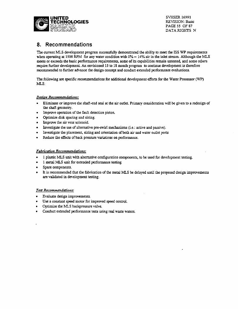
_ UNITED
TECHNOLOGIES
SVHSER 16991
REVISION: Basic
PAGE 55 OF 87
DATA RIGHTS N
8. Recommendations
The current MLS development program successfully demonstrated the ability to meet the ISS WP requirementswhen operating at 1900 RPM for any water condition with 0% - 14% air in the inlet stream. Although the MLS
meets or exceeds the basic performance requirements, some of its capabitifies remain untested, and some othersrequirefurtherdevelopment.An envisioned15to18 month program tocontinuedevelopmentistherefore
recommended to further advance the design concept and conduct extended performance evaluations.
The following axe specific recommendations for additional development efforts for the Water Processor (WP)IvILS:
Design Recommendations:
• Eliminate or improve the shaft-end seal at the air outlet. Primary consideration will be given to a redesign ofthe shaft geometry.
• Improve operation of the fault detection piston
• OpfimiTe disk spacing and sizing.
• Improve the air veto solenoid.
• Investigate the use of alternative pre-swirl mechanisms (i.e.: active and passive).
• Investigate the placement, sizing and orientation of both air and water outlet ports
• Reduce the effects of back pressure variations on performance.
Fabrication Recommenda_'ons:
• 1 plastic MLS unit with alternative configuration components, to be used for development testing.
• 1 metal MLS unit for extended performance testing
• Spare components.
• It is recommended that the fabrication of the metal MLS be delayed until the proposed design improvements
are validated in development testing.
Test Recommendations:
• Evaluate design improvements.
• Use a constant speed motor for improved speed control.
• Optimize the MLS backpressure valve.
• Conduct extended performance tests using real waste waters.

_ UNITEDTECHNOLOGIES_B_@_
SVHSER 16991
REVISION: Basic
PAGE 56 OF 87
DATA RIGHTS N
9. Appendix i: MLS Mini-Specification

_ UNITEDTECHNOLOGIESMAgqDLT@_
SVHSER 16991REVISION: Basic
PAGE 57 OF 87DATA RIGHTS N
MINI SPECIFICATION FOR THE WATER PROCESSOR
(WP) MOSTLY LIQUID SEPARATOR (MI.S)
Punx_:The purpose of this mini spedfication is to define the _ for the next generadon prototype MLS. Thissepam_fs continued development is on a r_earr.h and dcvelopmem contract from Ion mectronics and therefore the
listed am seen as design goals to be achieved through best efforts.
Item Name: Mostly Liquid Separator
Item Number:. 4703, rafenmce WP schematic SVSK116064
Description: Free gas separator with a direct drive motor, air outla solenoid valve, level sensing control and a speedSensor.
Function: Separate the fz_ gas from the WP inlet waste water.
Interfaces:
Mechanical - 1/2" lines (Water inlet & outlet - high flow)- 1/4" _ (Water outlet- low flow, 15-16.Spph)Electrical - 24 vdc
Fluid (1) - Internal ExternalMedia Waste Water & gas_ airTemper-aaa_ 65 to 113 F 65 to 113 F
System Inlet water press 0 to 10 psig N/ANK,S Outlet water press .5 to 10 psig N/A
Max operating presst_ 10 psig 14.7+/.2 psiaMax. particle _ 100 m N/ApH 5-8 N/ATOC 250 N/A
Performance Goals:
Inlet fi-_ gas (2)
MLS Inlet water flow rate
Outlet w'at_ flow ram
Proof pre_ma'e
Burst pressure
separator speed
0% to 100% rain/max
0% to 14% average
0 - 963 pph15 to 16.8 pph to pnx:ess pump, balance to tank
0.4% gas in water outlet0.0% warn" in gas outlet
20 _g40 psig0 -TBD rpm
Operation characteristicsOrientation
Start upLife
as a design goal tI_MLS opu_ inany lg&0g orientation
full ofwa)m or empty
87600 hrs as a design goal

_ UNITED
TECHNOLOGIES
Configuration:
Diaphragm seal
Del_ pr_r_ s_sing
SVHSER 16991
REVISION: Basic
PAGE 58 OF 87
DATA RIGHTS N
Shall be cksigned so as to not be over_
Deltap ports shall be provided for external sensing and separator
operation
Leakage." No vis_le leakage or damage is allowed when exposed to proof pressure for a minim, ma of fl_ minut_
Power consumption:No rcquirgme_ but _ should be m;nirni;,M
(reference flight requimmem = 30watts max, 10 warn nomiml)
Size & weight: TBD
Notes:
1. P,_fer to attachment I (Boeing Envelope Drawing 683-10019 Rev D, Table IV) for complete waste watermodelde/mifio_
2. Asmm_tion: Volumetric flow ram of the air = Vol of water

_ UNITEDTECHNOLOGIES SVHSER 16991
REVISION: BasicPAGE 59 OF 87DATA RIGHTS N
10. Appendix I!: MLS Plan of Test

_ UNITEDTECHNOLOGIES SVI-LSER 16991
REVISION: Basic
PAGE 60 OF 87
DATA RIGHTS N
TPION - 02
SPACE STATION WATER PROCESSOR
MOSTLY LIQUID SEPARATOR
(sis)
TEST PLAN
CONTRACT # NAS8-38250-12
Prepared forION ELECTRONICS6767 MADISON PIKE
HUNTSVILLE, AL 35806
Date issued
September 1994
Prepared byUNITED TECHNOLOGIES CORPORATION
HAMILTON STANDARD SPACE
SYSTEMS INTERNATIONAL INC.
WINDSOR LOCKS, CONNECTICUT 06096

_ UNITEDTECHNOLOGIES
TABLE OF CONTENTS
SVHSER 16991
REVISION: Basic
PAGE 61 OF 87
DATA RIGHTS N
1. INTRODUCTION: .................................... 62
2.BACKGROUND: ............ --=- ........ -.......... 64
3. TEST DESCRIPTION: ................................ -..................... 64
3.1Tr:_'r_: ...............................................................................................................................64
3.2 TESTSCHEDUt£:.................................................................................................................................. 65
4. TEST CONDITIONS ...................... 66
4.1 CHF.L'Xot.rr/SETUPTEST,BOTH S£:PARATORS:......................................................................................... 66
4.2 PE_t_RM_CETEST, BOTH SEPARATORS............................................................................................... 674.2.1 STAGE 1, Clean Water ................................................................................................................. 67
4.2.2 STAGE 2, PTrgin]gepon Soap ....................................................................................................... 71
4.2.3 Zero Gravity Performance, Plastic MZ,3 Only ................................................................................. 714.2.4STAGE3, Real Waste Water .......................................................................................................... 71
4.3 L_'I'F._G, METALMI._ ONLY ........................................................................................................ 72
5. TEST SYSTEM/ENVIROn: ........ 74
5.1 TEST SYSTEM:.....................................................................................................................................745.2 TEST_'_atIRONMENE............................................................................................................................ 74
List ofHgurmFIGURE 1-1: WATER PROCE.SSORWASTE WATER ORU .........................................................................63
FIcuRE 3-1: TEST PROGRAM SCHF_UL_ ............................................................................................... 66
FIGURE 4-1: CIIECKOUT TEST SCHEMATIC ............................................................................................ 69
F1CtrRE 4-2: PERFORM_CE/L_'E TEST SCn_ATXC .............................................................................. 70
List of Tabl¢_
TABLE 4-1:CHECKOUT TEST VERIFICATION LIST .................................................................................. 67
TABLE 4-2: PV._ORMANCE _ CON_DrrIoNs STEADY STATE FLt.rm FLOW .......................................... 68
TABLE 4-3: P_mro_',tA.SC_ TEST CONDrrIoNs TRANSI_CT FLt_ FLOW ............................................... 68
TABLE 4-4: PE_ORMANCE TEST CONDITIONS....................................................................................... 71TABLE 4-5: PERFORIVt_CE TE_ CONDITIONSTRANSIEN'f FLU1:D__,OW ............................................... 71
TABLg 4-6: MX,S _ TEST WASTE WATER .......................................................................................... 73TABLE 4-7: IGEPON SOAP TEST FORMULATION...................................................................................... 74

I UNITEDTECHNOLOGIES SVI-ISER 16991
REVISION: Basic
PAGE 62 OF 87
DATA RIGHTS N
10.1 Introduction:
This testplanhas been genem_ to¢v'alua_theimprovements,developedunderthiscontract,tothe Space
StationWaterProcessor(WP) MostlyLiquidSeparator(MLS).The MLS, item4703,isan _ component
in the Was= Water Orbital R__ Unit (WWORU) of the WP. T]_ WWORU schematic is shown inFigure 1.0-I. This ORU is rcspons_l¢ for rccciviag, degassing, and storage of the Space Station wast= water as
well as it provides the sys_n flow and pressure. The MLS is responsible for removing the free gas fi'om thewast= water. This separator must be capable ofhand_g gp to 900 pph inlet flow rate.
This testplan definesthe testsnecessaryto evaluatetwo new MLSs. (Dn¢ of thesewiZl be fzbdcm=:! fi'om a dea.rplastic_ polysulfone,forassistanceinvisualoperationchecksand theotherwillb¢f_ricatgdfrom flight
capable mamrial_ Parts for a thizd MLS will be available as spares or for use in fimzr¢ pmgr'am_ The twoassembled prototype unitswillbe ev_lumedm verifytheMLS's capability at a variety of operating conditions
including dJgercm inlet wazer aud air flow rat_.The MI.3 evaluationwillbe conductedm Ham/Iton StandardSpace Systems Intern_onars, HSSSI,
Engineering LaboreD' fscilitie_The MLS is covered under US Patem # 5,244,479 tiffed Liquid/Gas Separator For Soapy Liquid dated Sept. 14,1993.

UNITEDTECHNOLOGIES SVHSER 16991
REVISION: Basic
PAGE 63 OF 87
DATA RIGHTS N
\
|
_'TKur¢I0-I:Wafer Proctor ;F_ W_er ORU

_ UNITEDTECHNOLOGIES SVHSER 16991
REVISION: BasicPAGE 64 OF 87
DATA RIGHTS N
10.2 Background:
The MLS in the WP, along with all the otl_m"WWORU componenm, must be capable of surviving the harshenvironment inherant in the wasm wamr stream. In addition, the MLS must have an operational life of _m yearnAs a res_ of thc_ significant challenges for the MLS design, a development program was conduasd at HSSSI
as part of the Space Sta_on Program.A prototypeMI_ was original/ydev_oped fortheSpace StationPotableWater _r (PWP). This ML,S
concept was d_ign_l and fabricamd to handle tlm w'amr conditions of the PWP. Tim major PWP requimmnnmindudcd separating co_ wasm water and air at the maximum inlet flowram of 240 pph. This prototypeNK,S went throughsome cvolu_oninitsselxtrationtechnique.Some ofth_evolutionwas theresultofth_Spac_
Stationconfigurationchangingtoa combinedWaterProcessorCqCP).Th_ finaldc,,v2opedconceptincorporated
aseriesofthinrotating_ whichprovidedthgcentrifugalforcenged_ fortheak/wa_ separation.
Thisprototype,initsvariousconfigurations,was evalua_datFISSSIfrom thesecondquarter1990 to third
quarter1992.
The resultsfi'omthisprototypeindicatedthatthe separator was performingwith ao:x-ptablcmstltsin the
air/wa_ separationbutthattheconn'olmechanism intheMLS _ imp_ to handlethe WP
_mdition_Alsothenextgenerationsepam_r will require _ capacity in order to handle the larger inletflow ram of 900 pph for the WP.
10.3 Test Description:
The following sections identify the test objectives and the tcs_ program schedule.
10.3.1 Test Objectives:
The MLS testplancombinefourobjectives.The primaryobjectiveofthetestingwillbc tomap thepcrformanc_
oftheMI_ withintheexpectedoperatingconditions of the SpaceStationWaterProa:ssor.A s_ond objectiveof the MLS testingisto cl_nonstmmth_ insensitivityof the MLS to gravity,therd_
dcmo_g opcrabitityin a microgr'avity environment The insensitivity of the design to gravity will bedemonsWated by reprtxtadng test results in three different orientations while otxaating in a 1-g envim_
The thirdobjectiveofthetestingwillbe toidentify_ enhancementstotl_designoroperationof the
MLS. Theseenhancementsmay taketheformofopera."g changesorphysicaladjustmentsofthehardware.
The fourth objeai_ of the MLS tastingwillevaluatethelifechamctcd_'csofthemetalseparator.Thist_ing
willonlybe performedasscheduletimepermitsatth_conclu_onoftheperformancetssting_Thc_om the
durationofthistcs_isexpect_xltoonlylast_ w_'.ks.
Not_:Do toth_complexityofthetestprogramitmay benecessarytoalterthelestplandu.nngtcstingbasedontheresultsobtained.Ifthisoccurs,th_documentwillbemdlincdand IonElectronicsand NASA willbc notified
priortoconductingthered-linedtest

1UNITEDTECHNOLOGIES
10.4 Test Schedule:
SVHSER 16991
REVISION: Basic
PAGE 65 OF 87
DATA RIGHTS N
The testprogramscheduleisa_Jz_d inHgum 3-1.The testpmgz-amhas beendividedin)nthreephasesfor
eachofthetwo separator_The plasticseparatorwillbe testedfizstfollowedby themetalseparator.Thiswill
make itpossibletoincorporateinformationlearnedfi'omtheassemblyand operationoftheplasticMLS imo theconstnact/onand testingofth_metalseparator.
Tbe first phase of the t_st program for each _ cons/_ of the sctup/_out test. This phase will v_ifyindividual operation of both the mec]mnical and ¢lect_mechm_cal components within the separator. This_ut/se_zp willvcri_theproperassemblyoftheMLS assembly,limitswitchand solenoidvalveoperationand overallMLS opera,on.
The nextphaseofeach_ testingwillconsistofperformancetestingThe performancetestswillbe divided
intothreestage_The firststageofthepezformazx_testwillusedished water
and air to map the MLS performance at a wi_ varicay of liquid and gas flow _ This performan_ t_ing willalso be evaluating MLS performance versus rotational speed. Therdore this fizst stage of the performancemapping _ be donewith the_ operating between 800 and 1500 rpm.
The secondstageoftheperfornmn_testwillckrplicatemany ofthetestpointsfrom stageIbutwitha changeintheliquidphasecompos/t_on.Insteadofus/ngtl_distilledwaterofstageI,stage2 wig usea _ ofdistilled
water and virginIgepon soap.V'trginsoap and water m/xtums maximize the generationof soap Rxlm.
Tbemfor¢,itisanficipatadthu)thisstagewillcreatethe most di_cultchallengeforseparatorbasedon thelw.-viouspr_otspetest_
The thirdstageoftheperformancemappingwillalsorepeatmany ofthetestpointsfi'omstageI and 2but will
relyon arealwastewaterstreamcombinedwithairtochallengetheMI..S.
The third phase of testing will di_ez for each separaU_. The plastic MLS will be used to evaluam sens/dvity tozero gravity performance while the metal MLS will be Life)astexi on a real waste water solution.

_ UNITEDTECHNOLOGIES
SVHSER 16991
REVISION: BasicPAGE 66 OF 87
DATA RIGI-_S N
, II_k lu mlm_ Ilm
_l am Im hsll ml ,
Ll.*lla.m ll.hm-l_
1._ 1_ lU 3-141+.N i_l.* • |*.q*l.l_
CllSqgoe _ sin:Iv _ _t-lk_+.14 _1., • IO-lml-q,l
IIII_'T lmll,r Rlrr t,t_l _ lli_ s-la_-_t O.G a.l,_l-_
lira _ i_l To Im e.l_m a.* • S-_.14
_r mllm 1-q_-N _l.e • Jz**_l-)l
_ _ m 3-4km-N SSI.O • js.m.N
i*lu.m lee 4 11-w-_1
ILL _ =Ires m*l_._,* J4.o 4 31.#1_*s4
m - iw 1, _ iqw 13-1ml*N tO+e • tl-Jlm.ll
mU NU _. r0ml l_ _mi-N Jo.e • J=.,ll_lt
IILI. mmmT _ 14*l_el | • • )1-I*1._
ILl • I*I_-N S.+
ll,m. ,,IL icl_ ii_ _i ,.41_. i_ii t. Od :l'l .II*,i - I_
* _ "Pro + .I_,._,.gS ++I+.I, • II.W._..
PLI_ t _ mW_FTTI IIA U -_* I_ I+:14 L*LD st• ¢.
l • i j,l I s + 14 ;+) +J J ill
,++14 _
1,1e
m *.m..w.._
g
in
iii
I i
m
llml11_l_l m ll_'lqrsl,11 1 mUl LI_ILI -- (l_.rl.l I +k. I
kllS • + pmr M4_JI_ ...................................
F_gure 10-2: Te_ Program Schedules
10.5 Test Condib'ons
10.5.1 Checkout/Setup Test, Both Separators:
The checkouttestwillconfirmtheproperassemblyand operationofthe g'IXLrator.Table4,1-Icontainsa
detailedlistof theMLS oper_on thatwillbe verifiedduringthecheckza_phase.Figure4.1-Ishows the
simplifiedflow schemaZicthatw/.Ube useddm/ng the checkom phase.All ofthetestphasesw/Ifusea I00
micron_ter installedon the_ _ule__n_ Th_ filterw_l d_licatethelimitW pax_c/c_ found inthe
actualwasterwaterp_. Allofthetestingwillbeperformedwiththeseparatorshaftandaxisofrotationlyinginahor/+zonlalplaneunlessspecificallynotedotberwise_
ThecheckomtestwillbeperformedontheMLS prototypeun/tI (plastichousing)andwillberepeatedfortheprototS_unit2(metalhous/rg).
The _ e:ff_ will be moaitor_ throughom the checkout test. F-.ff_'tiveness will be cvalua_ based on
two prv=nine_ criteria. The _ criteria measures I/qu/d carryover in the _ gas vent. The secondczitc_will monitor g_s ca.,'_vv_ through the Ikl_d effluent lines. A qum_t_v¢ asscsszz_ of the= two c_itcria wi/l
provide an objective measur_mc_ of MLS performan_ at the diffen_ su_y-s_: flow conditions of thecheckout test.

_ UNITEDTECHNOLOGIES
Table 10-1: Checkout Test Verification ListSTEP TEST
SVHSER 16991
REVISION: BasicPAGE 67 OF 87DATA RIGHTS N
1. MLS Assembly
2. Proof Pressure
3.Speed Set
4, Sp_ Check
5. Vertical Mount
Operating Check
6. Low Level High LevelLimit Switch Checkout
7. Iv_,SFurl & Empty
Startup
I. Proper Assembly, No Drag2. Motor Separator Alignment OK, Coupling OK
3. Proper Motor Rotation
4. Speed (_oo-3ooo P,VM) Operation1. Perform proof pressure test to 20 psig, no damage allowed
after 5 minute exposure
R_lu_ment: Determine the minimum RPM which at whichno H20 is carried over in the gas vent for 3 control piston
spring settings (,in, reed& max.) and several gas and liquidflow iates.
1. Vary RPM from 1500 to 800 at each of the spring settings.
2. Select rain.RPM & spring setting._ement: Verify at selectedspring setting and several gas
and liquid flow rates that gas carry-over into the water outlet is0.4% or less.
1. Vary RPM from 800 to 1500 and check for gas in wateroutlet
2.Resclectmira RPM ifnecessary
(rerun step 3 if required)
1. Control piston up, verify operation with water flow at 60pph and 7% gas2. Control piston down, verify operation with water flow at 60
pph and 7% gas
1. Set limit switches to operate within the proper range
2. Verify solenoid valves operate in conjunction with limitswitches
I. "verify startup with no liquid flow
2. Verify startup flooded with water and no gas flow
10. 6 Performance Test, Both Separators
Perforama_ verification of the MI.S will consist of monitoring _mrator perfommace at a series ot"_eta_g
conditions. This section comists of three stages which include operation on dean water, virgin soap and thenreal wa._ water.
10.6.1 STAGE 1, Clean Water
The first stage of the performance test will use a distilled water and air mixtm_ to map the eff_ of the
separator. Table 4.2-1 lists the steady state liquid and gas flow rates to be tested daring this stag_. Tlm testschematicthat_ be used throughout the performance test which isd_gned todc_ly _mula_ operationwithin the waste v_mer p_r is shown in Figure 4-2.

_ UNITEDTECHNOLOGIES SVHSER 16991
REVISION: BasicPAGE 68 OF 87
DATA RIGHTS N
After mapping the su_dy-state flow conditions, the performance testing will investigate the separator'seffectiveness while operating through transien_ conditions. These test will transition from low to high liquid flowin rapid fashion (<5 seconds), operate briefly at the high flow (- 5 minutes) and return to the low liquid flowrat_ Table 4-3 details the transient fluid flows to be tested.
Table 10-2: Performance Test Conditions Steady State Fluid Flow
_qu_fzo_ (pph)
-- 0
60
100
50O
960
gas flow (volume % of liquid flow)
2% 6% 10% 14%
Table 10-3: Performance Test Conditions Transient Fluid Flow
liquid flow (pph) 2% Air 14% Air60 to 100 to 60
60 to 960 to 60

_ UNITEDTECHNOLOGIES_&BS_B_@59
SVHSER 16991
REVISION: Basic
PAGE 69 OF 87
DATA RIGHTS N
Ii
il
10
:i
: i
J
I •
1 ¢
=t
I
i
-" !i " 'r .... _ _
=-.-.
t
Figure 10-3: Checkout Test Scheman'c

_ UNITEDTECHNOLOGIES
SVI--ISER 16991
REVISION: Basic
PAGE 70 OF 87
DATA RIGHTS N
Figure 10-4: Pe_'ormance.:Life lest Scheman'c

_ UNITEDTECHNOLOGIES SVHSER 16991
REVISION: BasicPAGE 71 OF 86DATA RIGHTS N
10.6.2 STAGE 2, Virgin Igepon Soap
Duringthestage2 testingtheliqmdphasewillusea mixtureofdistilledwaterandvirginIgeponsoap.TheoonctmWationofthesoapis.425gmtpoundwater(identicaltothesoaptwa_ratioinhandwashandshowers).The Igepon soap compositionis defined in Table 4.5-2. The first step in the stage 2 testing will be a repeat of timspeed check from the checkom test (Table-4-1, step 4). Following tim speed check the second stage of thepexformam_test will duplicate the testpoints from thestage 1 perfomaa_ce test (Table 4.2).
The second stage performance test will also ctuplic_ tim transition flow test completed at the end of stage 1.These tests will relxat tlmconditions listed in Table 4-3 but wiU use tim distilled water,virgin soap, air mixtureused throughomstage 2.
10.6.3 Zero Gravity Performance, Plastic MI_ Only
Priorto progressingto stage 3 of theperformance test the plastic housing MLS will be evaluated in two alternateorientations to verify insensitivity to thegravity vector. These altmmm orientation tests will still _dy on the samevirgin Igeponsoap_ from stage 2. Both setups will positiontherotating shaft in the vertical plane.Thefirstorientationwillopcramwiththeinletportbelowtheseparator(Ic:controlpistonup).The second
orientationwillolxratewiththein/ctportabovetheseparmor(Ic:controlpistondown).Table4-4liststhesteady state opera/ing conditions for the two orientations.Table 4-5 lists the transient tests that will be performedin the two orientations.
Table 10.-4:Perfo_ 1"_tCo_ru
Steady StateFluidFlawAlterna_eOrientation
_dflow air flow (volmm % of liquid flow)
0% 2% 6%
6O
96O
10% 14%
quidSow60to100to60
60to960to6O
Table10-._PerformanceTestCon_'ioruTransie_FluidFlowAh_wna_Orlentmlon
2% Air 14% Air
10.6.4 STAGE 3, Real Waste Water
Throughout all of the stage 3 testingthe liquid phase will consist of real waste wateras defined in section 4.4.The first step in the stage 3 testing will also repeat the speed check from the checkouttest (Table 4-1, step 4).Next, the stage 3 performance test will then repeat the test points of stage 1 & 2. Table 4-2 _ the stcady-s_atcand Table 4-3 lists the transientliquid and gas flow ratesto be tested.

_ UNITEDTECHNOLOGIES •SVI-ISER 16991
REVISION: Basic
PAGE 72 OF 87
DATA RIGHTS N
10.7 Life Testing, Metal MLS Only
The lE¢tesfmgwillbe performedas frozeallowsand willbe performedalterthecheckoutand performance
mapping ontheMetalML_ unit2.The durationofthelEetestingwillbedeterminedby theremainingschedule
availableattheend ofthecheckoutand pezformancetests.The unitwillbedisassembledand _ afterthe
t=st.Any signsafwear,corrosionand co--on willberecordecL
The cpem_g condidonsforthetestwillbeasfollows:
1. Was_ Wat._ as defined in see'don 4.4
2. Liquid flow rate of 60 pph3. Gas flow at 7% of'liquid vo_c flow
4. Operating time to be 24 houxs per day, 7 days per w_,.k
4.4MLS LifeTestWaste WaterDefinition
The waste wa/ar to be used for the life testing will consist of shower, handwash, vacaaun distilled urine, aud
mouth wash water. The actual make up of the waste wa_ is de_ed in Table 4-6. Igepon soap 6503-454 andCrest toothpaste will be used for the testiag. The Igepon soap formulation is identified in Table 4-7.Oxonc and sulfuricacidwillbe used toprctrcalthedistilledurine.The Oxonc and _alfuricacidpretreat
concentrationsare5.0and 2.3grams/liarofurinerespectively.DeionJzedwaterwillbc used tosimulamthe
miaal flush water. The percemtagc of pretreated udue to flush watea" is 75% and 25% _ty.
Each waste water batch will be monitored and the data recorded for TOC, TC, co_'ty and ph Thiswaste
water will be used for both testing at HSSSI and for tbe suppliers lee tasting

_ UNITEDTECHNOLOGIES
Waste Water
Shower Water
(Igepon 6503-45-4)
Flavor Toottkuas_ )
UrineDistilla_
(Oxone/_SO4 Pretreat)
U_ Flush
I-Iand_ash
Fud C._
Wet Shave
Humidity Condensate
Spare Station 0b/day)
24.00
3.20
13.24
(4)
SVHSER 16991
REVISION: BasicPAGE 73 OF 87
DATA RIGHTS N
Space Station (%Total)
20.20
2.70
11.10
Test Water
(% Total)
50.10
2.70
14.80
4.40 3.70 (5)
24.00 20.20 (1)
11.74 9.90
3.00
20.20
2.30
6.70
100
3.52
24.00
Samples/Checks 2.72
Wash Cloth Bath
Total ]
(1) This water is included in the shower water
(2)Thiswat=risincludedm thefuelcellwater
(3) Deionizedwaterwillbeusedtosimulatethiswater
(4) PretreaI with 5 grams ofOxonc and 2.3 grams of sulfuric acid
(H2S04) b:to 6.25 cc offing*rim.liter of raw urine
32.40
(3)
(1)
(2)
(2)
(1)
100
(5) Mix 33.3°/, urineflush (I)l water) into urine prior todistfll,m'on
Table 10-6: MLS Life Test Waste Water

_ UNITEDTECHNOLOGIES SVHSER 16991
REVISION: Basic
PAGE 74 OF 87
DATA RICA--ITSN
Sh_,_.-la,_va.qhFormulation 650345-4
Ing_em % by weight
sodittm-n-cocon_ acid-n-m_ayl tattra_ (SCMT) 98.75(24% active)
]ecipur 95-F (soybean l_hin) 0.5OkrviquatFC-500 (,polyquatem/um16) 0.75
Table 10.7: Igepon So,zp Test Fo_n
10.8 Test System�Environment:
10.8.1 Test System:
Tbe system test _h_aatics shown in Figure 4-1 will be used for the checkout tests to be initially conducted oneach unit. The system t_ schematic shown in F/gum 4-2 will be used for the steady state and transient
pcrforman_ tc_'ts to be _ on each trail In addition, the schematic in Figu_ 4-2 will be _ed forthe life testing to be performed on the metal MLS at the completion of the ch_.ko= and performance testing. Allof the separator testing except for section 4.2.3 will be conducted with the rota_g shaft of the separator andmotor oriented horizontally.
10.9 Test Environment:
All tests will be conducted at a normal ambient conditions of approximataly:Atmospheric Pressure 14.7 +/- 0.3 psi, l_lativ¢ Humidity 30 - 80°/_
Temperam_ 70 +/- 5 F,

UNITEDTECHNOLOGIES SVHSER 16991
REVISION: BasicPAGE 75 OF 87DATA RIGHTS N
11. Appendix I!1: MLS Extended Performance Test Plan

_ UNITEDTECHNOLOGIES SVHSER 16991
REVISION: Basic
PAGE 76 OF 86DATA RIGHTS N
SPACE STATION WATER PROCESSORMOSTLY LIQUID SEPARATOR
(MLS)Extended Performance TEST PLAN
Contract # NAS8-38250-12
Prepared forION Electronics
6767 Madison Pike
Huntsville, AL 35806
Revised
April 17, 1995
Prepared ByUNITED TECHNOLOGIES CORPORATION
HAMILTON STANDARD SPACE SYSTEMS INTERNATIONAL INC.
WINDSOR LOCKS, CT 06096

_ UNITEDTECHNOLOGIES SvHs_ 16991
_V_@_@ PAGE 77 oF sTDATA RIGHTS N
TABLE OF CONTENTS
I. INTRODUCTION .......................................... 78
2. TEST DESCRIPTION ...................................... 78
.............. 782 1 TEST OBJECTIVES ................... • ........
2.2 TEST SCHEDULE .......................................... 78
3. TEST CONDITIONS ....................................... 79
3.1 CHECKOUT .............................................. 79
3.2 VERIFICATION ........................................... 81
3.2.1 Clean Water ...................................... 81
3.2 2 Shower Water ..................................... 82
3.3 EXTENDED PERFORMANCE TEST ................................ 83
3.4 CHECK FOR PERFORMANCE DEGRADATION ................. , ........ 85
4. TEST SYSTEM AND ENVIRONMENT ........................... 86
4.1 TEST SYSTEM ........................................... 86
4.2 TEST ENVIRONMENT ....................................... 86
Table of Figures
F[GUP.E3-1.............................................................. ................................................................................ 80
I_Gu_z3-2 .............................................................................................................................................. 84

_ UNITEDTECHNOLOGIES SVHSER 16991
REVISION: BasicPAGE 78 OF 87
DATA RIGHTS N
11.1 Introduction
This test plande_'nbestheMLS Extended Performance Testing that wiU be performed using the metal MLS unit. Suchtcstfng is part of a larger MLS test effort, which is descnl0ed in the overall MLS Test Plan, last revised in December
1994. This test plan is meant as a supplement to the overall one. The objective of this document is to define the testconditions to be used during the Extended Performance Testing. In cruses where this document differs from theaforementioned MLS Test Plan, this test plan will supersede the original The overall scope and objcx_tive of the original
test plan are not affected.
The Metal MLS unit is one of two assembled prototype units that are being evaluated to verify the MLS' capabilities in avariety of operating conditions.
This additional test plan is created to take advantage of what has been learned about the operation of the plastic MLSunit thus fax. In addition, it allows Extended Performance Testing to occur in pamllcl with continued performance
testing. This will allow more time in aa Extended Performance Test than originally envisioned, and will also allow timeto explore some further refinement(s) to the plastic MLS unit.
As stated in the overall Test Plan, testing will be conducted at Hamilton Standaxd Space & Sea Systems (HSD S&SS)Advanced Engineering Laboratory.
The MLS is covered under US Patent 5,244,479 tiffed Liquid/Gas Separator For Soapy Liquid, dated Sept 14, 1993.
11.2 Test Description
The following sections identify the test objectives and schedule.
11.2.1 Test Objectives
The objectives of )h_¢ test arc a subset of those described in the overall MLS Test Plan, and arc:
To verify that the performance of the Metal MLS unit is the same as that of the plastic MLS unit (descn'bed and tested
per the overall MLS Test Plan).
To evaluate the endurance characteristics of the Metal MLS unit within the allowable time left for the overall MI.,S
program.Of prime concernistheoperationofthecontrolpistonand thediaphragm air-seal.
To identifyany potenRalenhancementstothedesignoroperationoftheMLS. These enhancementsmay taketheform
ofactualorrecommended operatingchangesorphysicaladjustmentstothehardware.
11.2.2 Test Schedule
The Mete/MLS Testisdividedintofourphases:
The firstphaseWIU consistofthesetup/checkoutofthemetalMLS unit.Pans needingrework to make their
configuration the same as that which currently exists on the plastic MLS unit will be performed, u_li_ng the

_ UNITEDTECHNOLOGIES SVI-/SER 16991
REVISION: Basic
PAGE 79 OF 87DATA RIGHTS N
information learned thus far in MLS operation and testing. This phase will verify the proper operation of both themechanical and ¢lectromechanical components within the separator, and also of the overall assembly.
The second phase will consist of verification of the performance of the Metal MLS unit. This will consist of mapping the
performance of the unit using both clean water and shower water, and comparing the results with those obtained usingthe plastic MLS unit under similar conditions.
The third phase will consist of the actual Extended Performance Testing of the Metal MLS unit. Testing will b¢performed using a low inlet flow (60-100 pph), 14°/. Air in the inlet flow, and shower water. This phase will continuefor the maximum _rne allowable.
The fourth phase will consist of re-mapping the performance of'the unit using shower water after the completion of thethird phase, and comparing the results with those obtained in the second phase of this test. This will document any
performance degradation that may have occurred, and will aid in the post-test teardown inspection and report writ_-up.
11.3 Test Conditions
11.3.1 Checkout
The checkout phase will confirm the proper assembly and operation of the separator. Table 3-1 lists the operational
characteristics to be verified during this test phase. This phase will be conducted using the test rig used for the teeing ofthe plastic MLS unit, shown schematically in Figure 3-1.
All test phases will use a 100 micron falter in the MLS inlet line. This filter will simulate space Right conditions. TheMLS unit will be in a horizontal orientation for this phase.
Table II-I
STEP [I.MLS A._mbty
2. Proof Pressure
TESTI I
1. Proper assembly, No drag_2. MotodSeparator alignment OK
3. Coupling OK
4.PropcrMotor Operation(Speed,Rotation)
I.Performproofpressuretestto20 PSIG, no
damage allowedafter5 minuteexposureat
pressure.

UNITEDTECHNOLOGIESHA_0LT©_
SVI-ISER 16991
REVISION: Bas/c
PAGE 80 OF 87
DATA RIGHTS N
Checkout and Verification Test-SetupSchematic
F/gure 11-1
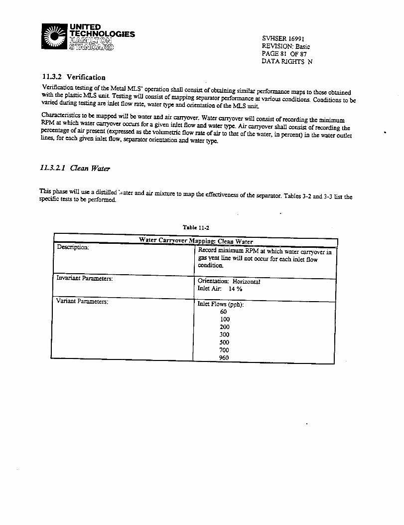
_ UNITED
TECHNOLOGIES SVHSER 16991REVISION: Basic
PAGE 81 OF 87DATA RIGHTS N
11.3.2 Verification
VerificationtestingoftheMetal MLS' operationshallconsistofobtainingsimilarperformancemaps tothoseobtained
with the plastic MLS tait. Testing will con.dst of mapping separator performance at various conditions. Conditions to be
varied during testing are inlet flow rate, water type and orientation of the MLS unit.
Characteristic, to be mapped will be water and air carryover. Water carryov_ will consist of recording the minimumRPM at which water carryover occurs for a given inlet flow and water type. Air carryover shall consist of recording the
percentage of air present (expressed as the volumetric flow rate of air to that of the water, in percent) in the water outletlines, for each given inlet flow, separator orientation and water type.
11.3.2.1 Clean Water
This phase will use a distiUed "rater and air mLxn_ to map the effectiveness of the separator. Tables 3-2 and 3-3 list thespecific tests to be performed.
Table 11-2
Description:
Invariam Parameters:
VariantParameters:
Water Carryover., Mapping: Clean Water
Record minimum RPM at which water carryover ingas yent Line will not occur for each inlet flowcondifiom
Ch_enmdon" Horizontal
Inlet Air:. 14 %
Inlet Flows (pph):6O
I00200
3OO_00
700
960

_ UNITED
TECHNOLOGIES
Table 11-3
SVHSER 16991REVISION: Basic
PAGE 82 OF 87DATA RIGHTS N
Descr/ption:
Invariant Parameters:
Variant Parameters:
Air Carr_ over Ma I)ping: ,Clean WaterRecord Percent Air on Water outlet lines for each
inlet flow condition.
Orientation: Horizontal
Inlet Air: 14 %RPM: 1900
Inlet Flows (pph):60100
2O03O0
50070O
960
11.3.2.2 Shower Water
This phase will use a shower water and air mixture to map the effectiveness of the separator. Tables 3-4 and 3-5 list thespecificteststobe performed. Air carryover data will be collectedwiththeMLS m both the Horizontal and Vertical(inlet down) orientations.
Table 11-4
Dcscripdon:
lavariant Parameters:
Variant Parameters:
Water CarrTover Mapping: Shower Water
Record minimum RPM at which water carryover in gasvent line will not occur for each inlet flow condition.
Inlet Flows (pph):6O
100200
3OO$00
700960
Orientation:Horizontal
Inlet Air:. 14 %

_ UNITEDTECHNOLOGIES
Table 11-5
SVI--ISER16991
REVISION: Basic
PAGE 83 OF 87
DATA RIGHTS N
Description"
Invariant Parameters:
Variant Parameters:
Air Carryover M_ _pping: Shower WaterRecord Percent Air on Water outlet lines for each inletflow condition.
Orientation:Horizontal
InletAir:. 14%RPM: 1900
I.Orientation"
Horizontal
Vertical
2.InletFlows (pph):60
100
2OO
300
5OO
700
960
11.3.3 Extended Performance Test
The Extended Performance Test phase will be performed after the checkout and verification testing is complete, and will
lastfor approximately one month (theactual durationwillbe affectedby theremain/ngscheduleleft in theoverall
program).
Thisphasewillrun theMetal MLS ina testsetupshown schematicallyinFigure3-2.Testingwilloccurapproximately
ninehoursperday and willoccuron workdaysonly.
Replenish.mereofshowerwaterwilloccuron an asnccdcdbasis.
Table3-6 liststhespecificparametersforthistestphase.

_ UNITEDTECHNOLOGIES SVI-ISER 16991
REVISION: Basic
PAGE 84 OF 87
DATA RIGHTS N
C,_rd
v,_,
a- to_
Rd_'V_
Spud
Extended Performance Test-Setup Schematic
F_ 11-2
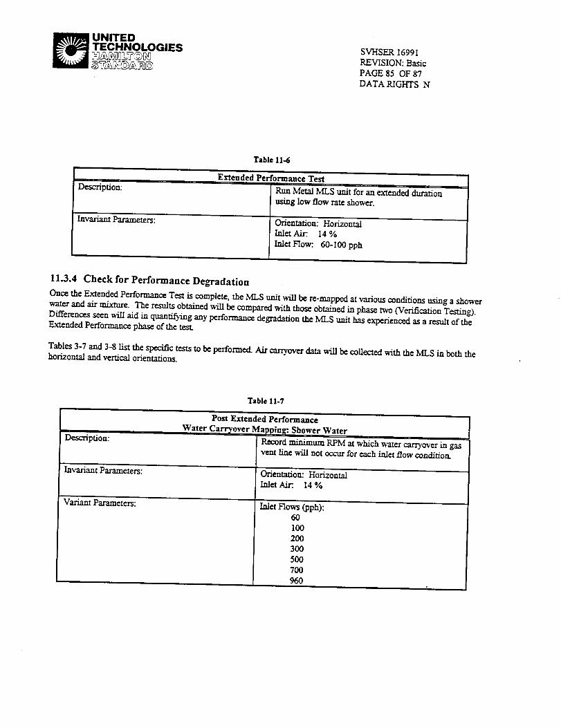
_ UNITED
TECHNOLOGIES SVHSER 16991
REVISION: BasicPAGE 35 OF 87
DATA RIGHTS N
Table 11-6
Description:
Invaxiant Parameters:
Extended Performance Test
Run Metal MLS unit'for an extended duration
using low flow rate shower.
Orientation: HorizontalInlet Air:. 14 %
Inlet Flow: 60-I00 pph
11.3.4 Check for Performance Degradation
Once the Extended Performance Test is complete, the MLS unit will be re-mapped at various conditions using a showerwater and air mixture. The results obtained will be compared with those obtained in phase two (Verification Testing).Differences seen will aid in quantifying any performance degradation the MLS unit has experienced as a result of theExtended Performance phase of the
Tables 3-7 and 3-8 List the specific tests to be performed. Air carryover data will be collected with the MLS in both thehorizontal and vertical orientations.
Table I1-7
II
Description:
Invariant Parameters:
Variant Parameters:
Post Extended Performance
Water Carryover 1_[app|ng: Shower Water
Record minimum RPM at which water carryover in gasvent line will not occur for each inlet flow cond/t/on.
Orientation: Horizontal
Inlet Air:. 14 %
Inlet Flows (pph):6OI00
2O03OO500
7OO
960

_ UNITEDTECHNOLOGIES
Table 11-8
SVHSER 16991REVISION: BasicPAGE 86 OF 87
DATA RIGHTS N
Description:
Invarianl Parameters:
Variant Parameters:
Post Extended Performance
Air Carryover M,"pping: Shower Water
Record percent _ on wa_r outlet lines for each talerflow condition.
Orientation"Horizontal
laletAir:. 14 %
RPM: 1900
I.Orientation:
HorizontalVertical
2. In/et Flows (pph):60I00
2003OO
5007OO960
11.4 Test System and Environment
11,4.1 Test System
The Checkout,Verificationand Post-ExtendedPerformanceTestverificationwillbe conductedon thetestrigusedto
testtheplasticMLS unit.Thissetupisshown schcmatlcailyinFigure3-I.
The Extended Performancetestwillbcconductedon a secondsimplifiedrigset-up,shown schematicallyinFigure3-2.
11.4.2 Test Environment
Alltestswillbcconductedatroom temperatureconditions:Temperature70 + 5 °F,AnnosphcricPressm'c14.7_.+0.3
psi,RelativeHumidity30 -80 % (allapproximate).

_ UNITEDTECHNOLOGIES SVHSER 16991
REVISION: BasicPAGE 87 OF 87
DATA RIGHTS N
12. Appendix IV: Photographs

i-iI

I/)
m
\
i "
!


![Springer Pub. Co. Prototyping on the PC with Programmable ... · and Abbott 1994], the CLP (Configurable Logic Processor) VMEbus machine vision processor [Dunn 1995], the TERAMAC](https://img.pdfslide.net/doc/110x75/5fafa21435003956890f382a/springer-pub-co-prototyping-on-the-pc-with-programmable-and-abbott-1994.jpg)