Embed Size (px)
Citation preview
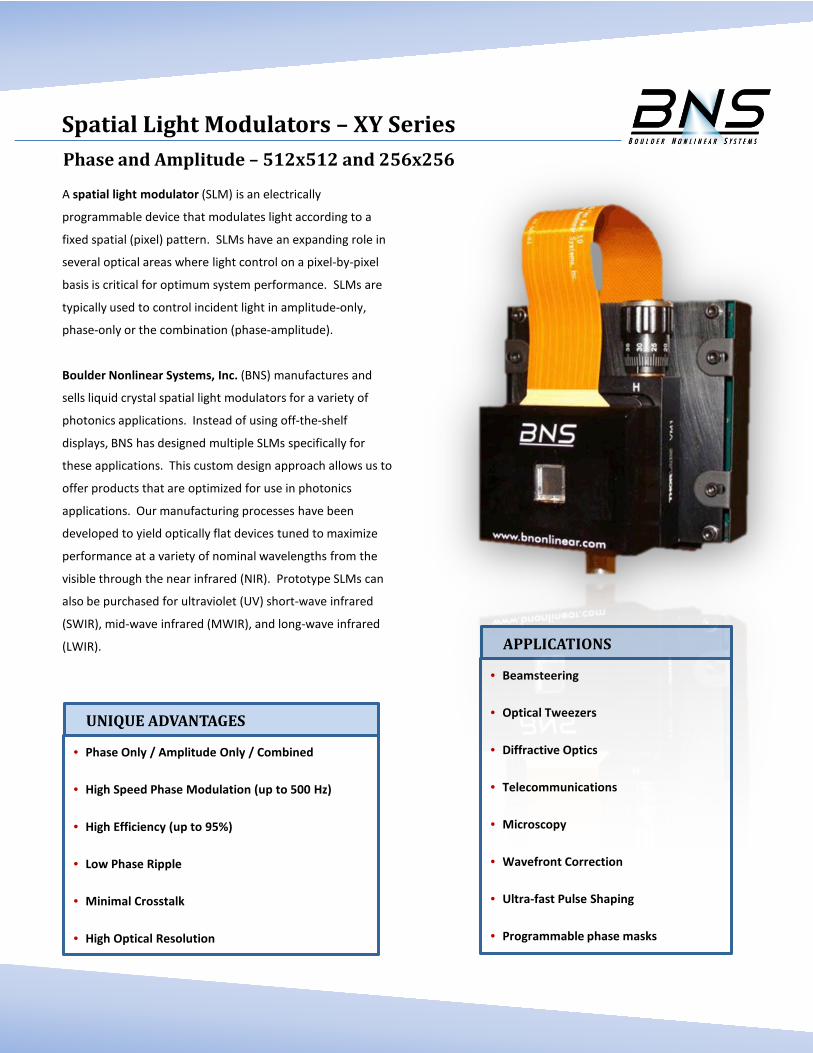
Phase and Amplitude – 512x512 and 256x256
A spatial light modulator (SLM) is an electrically
programmable device that modulates light according to a
fixed spatial (pixel) pattern. SLMs have an expanding role in
several optical areas where light control on a pixel-by-pixel
basis is critical for optimum system performance. SLMs are
typically used to control incident light in amplitude-only,
phase-only or the combination (phase-amplitude).
Boulder Nonlinear Systems, Inc. (BNS) manufactures and
sells liquid crystal spatial light modulators for a variety of
photonics applications. Instead of using off-the-shelf
displays, BNS has designed multiple SLMs specifically for
these applications. This custom design approach allows us to
offer products that are optimized for use in photonics
applications. Our manufacturing processes have been
developed to yield optically flat devices tuned to maximize
performance at a variety of nominal wavelengths from the
visible through the near infrared (NIR). Prototype SLMs can
also be purchased for ultraviolet (UV) short-wave infrared
(SWIR), mid-wave infrared (MWIR), and long-wave infrared
(LWIR).
UNIQUE ADVANTAGES
Spatial Light Modulators – XY Series
• Phase Only / Amplitude Only / Combined
• High Speed Phase Modulation (up to 500 Hz)
• High Efficiency (up to 95%)
• Low Phase Ripple
• Minimal Crosstalk
• High Optical Resolution
APPLICATIONS
• Beamsteering
• Optical Tweezers
• Diffractive Optics
• Telecommunications
• Microscopy
• Wavefront Correction
• Ultra-fast Pulse Shaping
• Programmable phase masks
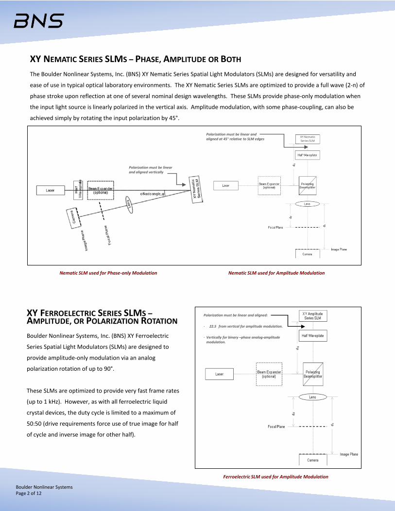
XY NEMATIC SERIES SLMS – PHASE, AMPLITUDE OR BOTH
The Boulder Nonlinear Systems, Inc. (BNS) XY Nematic Series Spatial Light Modulators (SLMs) are designed for versatility and
ease of use in typical optical laboratory environments. The XY Nematic Series SLMs are optimized to provide a full wave (2-п) of
phase stroke upon reflection at one of several nominal design wavelengths. These SLMs provide phase-only modulation when
the input light source is linearly polarized in the vertical axis. Amplitude modulation, with some phase-coupling, can also be
achieved simply by rotating the input polarization by 45°.
Polarization must be linear and aligned at 45° relative to SLM edges
Polarization must be linear and aligned vertically
XY Nematic Series SLM
XY FERROELECTRIC SERIES SLMS – AMPLITUDE, OR POLARIZATION ROTATION
Boulder Nonlinear Systems, Inc. (BNS) XY Ferroelectric
Series Spatial Light Modulators (SLMs) are designed to
provide amplitude-only modulation via an analog
polarization rotation of up to 90°.
These SLMs are optimized to provide very fast frame rates
(up to 1 kHz). However, as with all ferroelectric liquid
crystal devices, the duty cycle is limited to a maximum of
50:50 (drive requirements force use of true image for half
of cycle and inverse image for other half).
Ferroelectric SLM used for Amplitude Modulation
Polarization must be linear and aligned:
∙ 22.5 from vertical for amplitude modulation.
∙ Vertically for binary –phase analog-amplitude modulation.
Nematic SLM used for Phase-only Modulation Nematic SLM used for Amplitude Modulation
Boulder Nonlinear Systems Page 2 of 12
BNS UNIQUE FEATURES
BNS has developed many unique liquid crystal spatial light modulators over the past two decades. Through this development
process, there has been an advancement of SLM performance unmatched by any other company. Such performance
enhancement includes:
• Sub-millisecond frame loading to prevent phase droop and addressing latency
• 100% fill factor to reduce higher-order diffraction
• Intra-pixel-pair modulo-2π phase transitions to maximize space bandwidth
• Customized manufacturing processes to achieve optically flat performance
• Phase-only liquid crystal response times
• 16-bit control electronics provides over 500 linear optical phase levels on the SLM.
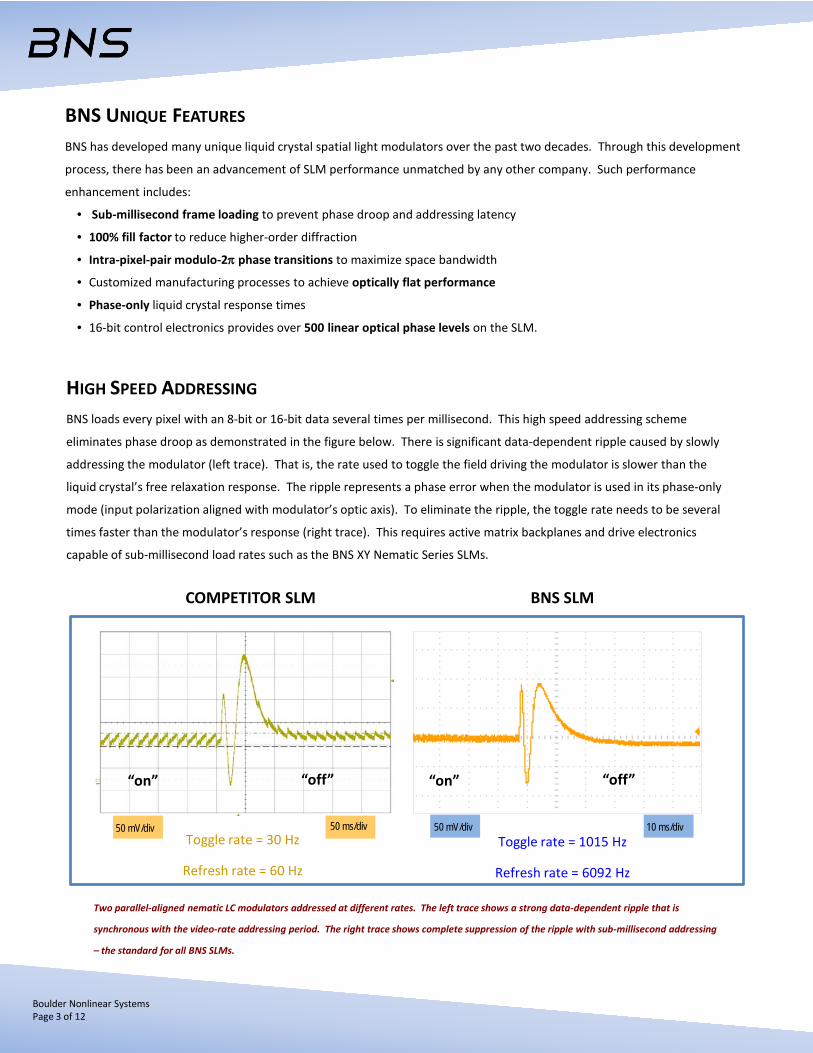
HIGH SPEED ADDRESSING
BNS loads every pixel with an 8-bit or 16-bit data several times per millisecond. This high speed addressing scheme
eliminates phase droop as demonstrated in the figure below. There is significant data-dependent ripple caused by slowly
addressing the modulator (left trace). That is, the rate used to toggle the field driving the modulator is slower than the
liquid crystal’s free relaxation response. The ripple represents a phase error when the modulator is used in its phase-only
mode (input polarization aligned with modulator’s optic axis). To eliminate the ripple, the toggle rate needs to be several
times faster than the modulator’s response (right trace). This requires active matrix backplanes and drive electronics
capable of sub-millisecond load rates such as the BNS XY Nematic Series SLMs.
Toggle rate = 30 Hz
Refresh rate = 60 Hz
Toggle rate = 1015 Hz
Refresh rate = 6092 Hz
50 mV/div 50 ms/div 50 mV/div 10 ms/div
“on” “off” “on” “off”
Two parallel-aligned nematic LC modulators addressed at different rates. The left trace shows a strong data-dependent ripple that is
synchronous with the video-rate addressing period. The right trace shows complete suppression of the ripple with sub-millisecond addressing
– the standard for all BNS SLMs.
COMPETITOR SLM BNS SLM
Boulder Nonlinear Systems Page 3 of 12
Boulder Nonlinear Systems Page 4 of 12
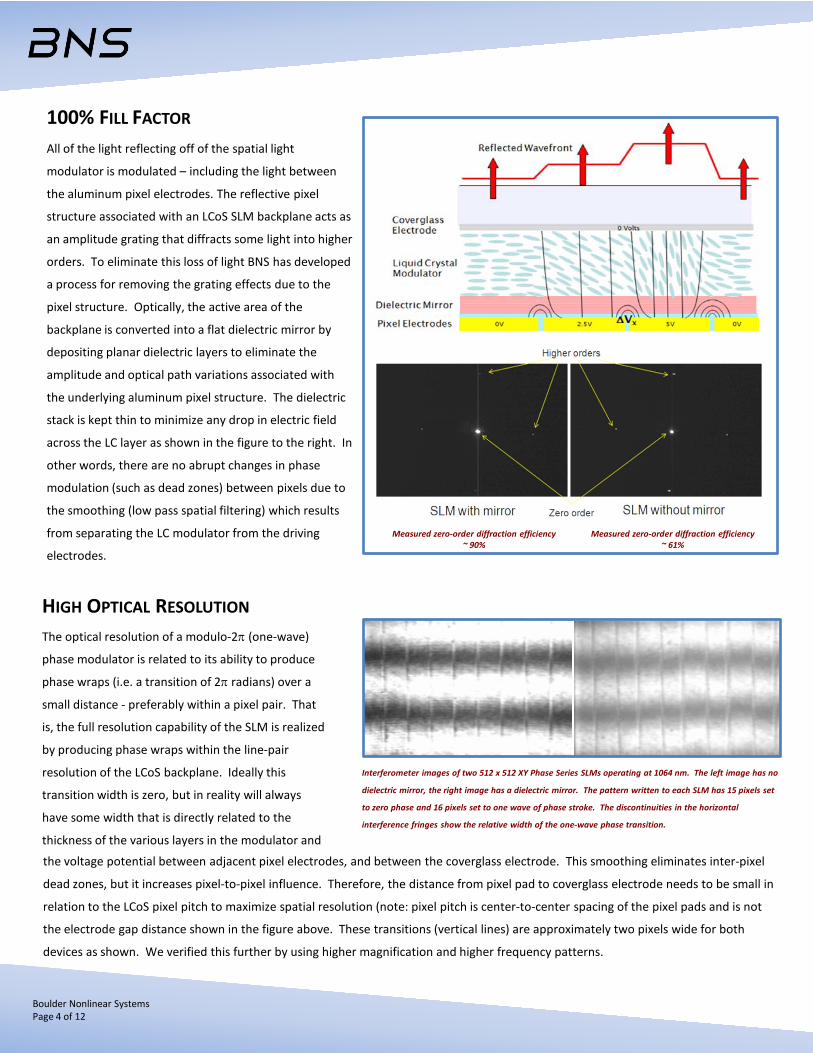
100% FILL FACTOR
All of the light reflecting off of the spatial light
modulator is modulated – including the light between
the aluminum pixel electrodes. The reflective pixel
structure associated with an LCoS SLM backplane acts as
an amplitude grating that diffracts some light into higher
orders. To eliminate this loss of light BNS has developed
a process for removing the grating effects due to the
pixel structure. Optically, the active area of the
backplane is converted into a flat dielectric mirror by
depositing planar dielectric layers to eliminate the
amplitude and optical path variations associated with
the underlying aluminum pixel structure. The dielectric
stack is kept thin to minimize any drop in electric field
across the LC layer as shown in the figure to the right. In
other words, there are no abrupt changes in phase
modulation (such as dead zones) between pixels due to
the smoothing (low pass spatial filtering) which results
from separating the LC modulator from the driving
electrodes.
HIGH OPTICAL RESOLUTION
The optical resolution of a modulo-2π (one-wave)
phase modulator is related to its ability to produce
phase wraps (i.e. a transition of 2π radians) over a
small distance - preferably within a pixel pair. That
is, the full resolution capability of the SLM is realized
by producing phase wraps within the line-pair
resolution of the LCoS backplane. Ideally this
transition width is zero, but in reality will always
have some width that is directly related to the
thickness of the various layers in the modulator and
Interferometer images of two 512 x 512 XY Phase Series SLMs operating at 1064 nm. The left image has no
dielectric mirror, the right image has a dielectric mirror. The pattern written to each SLM has 15 pixels set
to zero phase and 16 pixels set to one wave of phase stroke. The discontinuities in the horizontal
interference fringes show the relative width of the one-wave phase transition.
the voltage potential between adjacent pixel electrodes, and between the coverglass electrode. This smoothing eliminates inter-pixel
dead zones, but it increases pixel-to-pixel influence. Therefore, the distance from pixel pad to coverglass electrode needs to be small in
relation to the LCoS pixel pitch to maximize spatial resolution (note: pixel pitch is center-to-center spacing of the pixel pads and is not
the electrode gap distance shown in the figure above. These transitions (vertical lines) are approximately two pixels wide for both
devices as shown. We verified this further by using higher magnification and higher frequency patterns.
Measured zero-order diffraction efficiency ~ 90%
Measured zero-order diffraction efficiency ~ 61%
Boulder Nonlinear Systems Page 5 of 12
LCoS SLM CONTROLLER INTERFACE OPTIONS
Introduction BNS offers three hardware interface options for our LCoS SLMs: PCI Express (PCIe) 8 and 12-bit, or DVI 16-bit offering added
flexibility to meet the most demanding customer applications. DVI For applications that are not concerned with latency or exact timing, but that desire a standard video interface to the SLM this is
an appropriate hardware choice. This controller provides 16-bit pixel data to the SLM. Calibrations of the nonlinear optical
response of the liquid crystal to voltage can be loaded to the hardware, thus reducing system latency, and minimizing the need for
the customer to understand the procedure to apply the calibration.
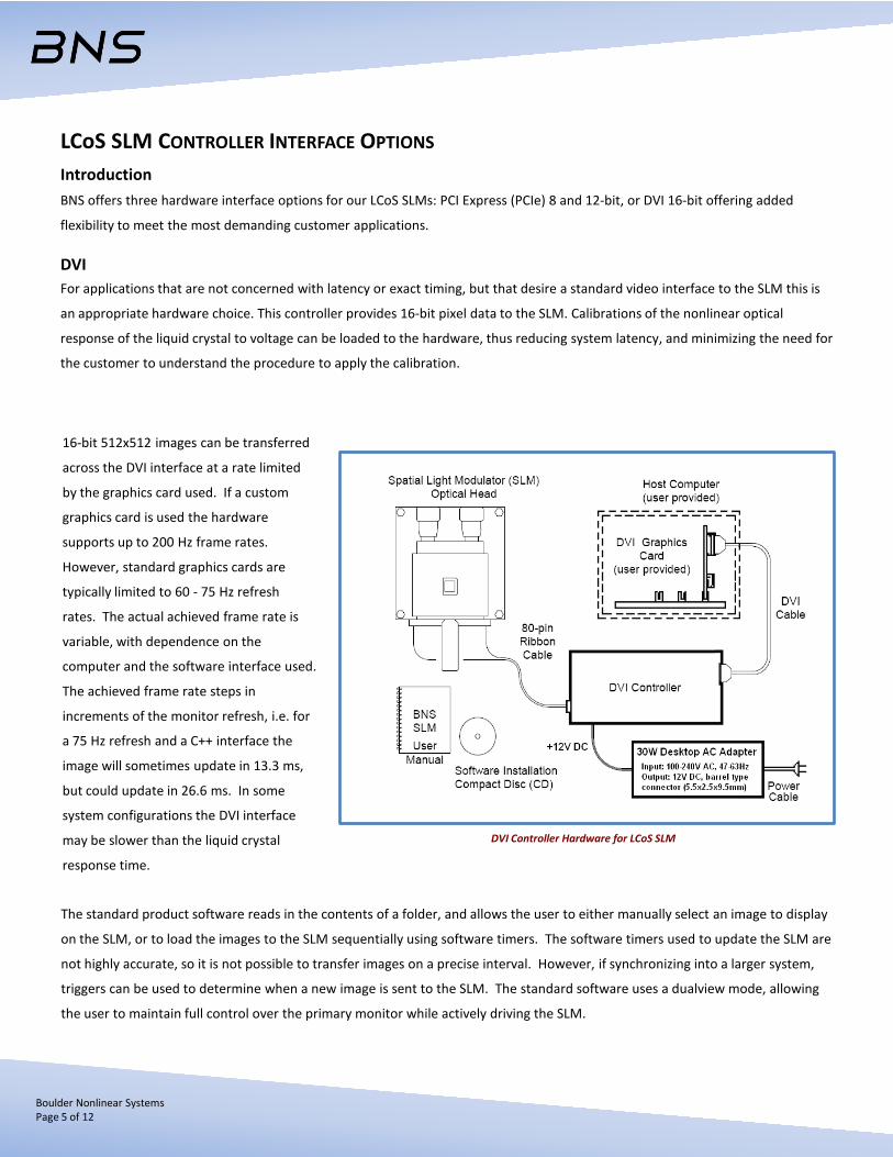
16-bit 512x512 images can be transferred
across the DVI interface at a rate limited
by the graphics card used. If a custom
graphics card is used the hardware
supports up to 200 Hz frame rates.
However, standard graphics cards are
typically limited to 60 - 75 Hz refresh
rates. The actual achieved frame rate is
variable, with dependence on the
computer and the software interface used.
The achieved frame rate steps in
increments of the monitor refresh, i.e. for
a 75 Hz refresh and a C++ interface the
image will sometimes update in 13.3 ms,
but could update in 26.6 ms. In some
system configurations the DVI interface
may be slower than the liquid crystal
response time.
The standard product software reads in the contents of a folder, and allows the user to either manually select an image to display
on the SLM, or to load the images to the SLM sequentially using software timers. The software timers used to update the SLM are
not highly accurate, so it is not possible to transfer images on a precise interval. However, if synchronizing into a larger system,
triggers can be used to determine when a new image is sent to the SLM. The standard software uses a dualview mode, allowing
the user to maintain full control over the primary monitor while actively driving the SLM.
DVI Controller Hardware for LCoS SLM

Boulder Nonlinear Systems Page 6 of 12
LCoS SLM CONTROLLER INTERFACE OPTIONS
DVI continued… In order to support 16-bit operation, 24-bit images are used, where 8-bits are blue, 8-bits are green, and 8-bits are red. The blue
bits are ignored by the hardware, the green bits are the 8 most significant bits, and the red bits are the 8 least significant bits. If 8-
bit images are loaded to the SLM through the BNS software interface, the 8-bits are assigned to the 8 most significant bits. These
images will appear green in the user interface. Images are transferred through the graphics card, meaning that the graphics card
settings are critical to the operation of the SLM. Specifically, using the nVidia NVS 290 256MB dual DVI Graphics card, gamma
must be set to 50% to get the expected mapping of input values to output values after passing through the graphics card, and for
the BNS supplied LUT calibration to function properly. BNS cannot guarantee identical operation for all graphics cards. If a
different graphics card is used it is recommended that the SLM calibrations be verified prior to use. PCIe 8- and 16-bit For applications that require minimal latency such as atmospheric turbulence simulation/correction or real-time optical trapping
systems the PCIe interface is an appropriate choice.
This controller provides 8- or 16-bit pixel data to the SLM. Calibrations of the nonlinear optical response of the liquid crystal to
voltage can be loaded to the hardware, thus reducing system latency, and minimizing the need for the customer to understand
the procedure to apply the calibration.
8-bit 512x512 images can be transferred across the PCIe bus in approximately 600 us using an x4, or larger PCIe slot. 16-bit
512x512 images can be transferred at the same rate but requires a x8, or larger, PCIe slot.
Spatial Light Modulator (SLM) Optical Head
Host Computer (user provided)
PCIe Cable
PCIe Controller Electronics
Software Installation
BNS SLM
User Manual
PCIe Interface
Power Cable
The standard product software reads
in the contents of a folder, and allows
the user to either manually select an
image to display on the SLM, or to load
the images to the SLM sequentially
using software timers. Software
timers are not highly accurate, so it is
not possible to transfer images on a
precise interval. However, if
synchronizing into a larger system,
triggers can be used to determine
when a new image is on the SLM.
PCIe Controller Hardware for LCoS SLM
Boulder Nonlinear Systems Page 7 of 12
HOST COMPUTER REQUIREMENTS
In order to effectively utilize your BNS SLM, basic computing hardware is required. The following components are essential to
properly achieve the full performance of your SLM system.
• Operating system(s): Windows XP Professional SP3 (32-bit), Windows Vista Sp2 (32- and 64-bit) or Windows 7 (32- and 64-bit).
• Dual-core processor and 1 GB of RAM (minimum).
• Depending on the type of controller selected:
- PCIe 8-bit– one open x4, or larger PCIe slot
- PCIe 16-bit- one open x8, or larger PCIe slot
- DVI – Graphics controller with available DVI-D connector. SLM CONSTRUCTION
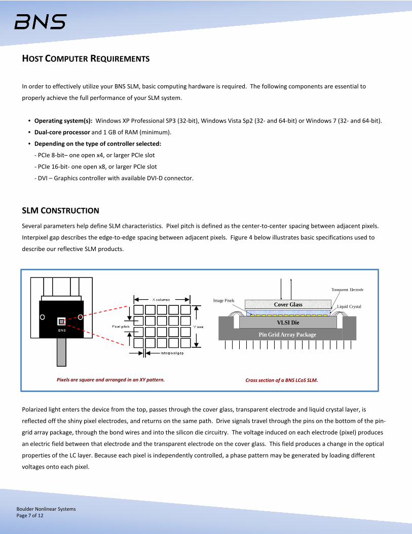
Several parameters help define SLM characteristics. Pixel pitch is defined as the center-to-center spacing between adjacent pixels.
Interpixel gap describes the edge-to-edge spacing between adjacent pixels. Figure 4 below illustrates basic specifications used to
describe our reflective SLM products.
Polarized light enters the device from the top, passes through the cover glass, transparent electrode and liquid crystal layer, is
reflected off the shiny pixel electrodes, and returns on the same path. Drive signals travel through the pins on the bottom of the pin-
grid array package, through the bond wires and into the silicon die circuitry. The voltage induced on each electrode (pixel) produces
an electric field between that electrode and the transparent electrode on the cover glass. This field produces a change in the optical
properties of the LC layer. Because each pixel is independently controlled, a phase pattern may be generated by loading different
voltages onto each pixel.
Pin Grid Array Package
Cover Glass
VLSI Die
Image PixelsLiquid Crystal
Transparent Electrode
Pixels are square and arranged in an XY pattern. Cross section of a BNS LCoS SLM.
Boulder Nonlinear Systems Page 8 of 12
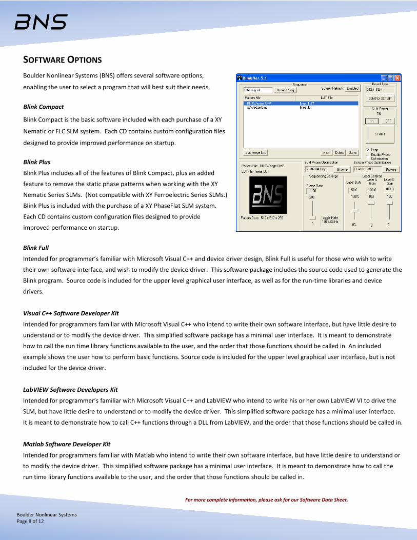
SOFTWARE OPTIONS
Boulder Nonlinear Systems (BNS) offers several software options,
enabling the user to select a program that will best suit their needs.
Blink Compact
Blink Compact is the basic software included with each purchase of a XY
Nematic or FLC SLM system. Each CD contains custom configuration files
designed to provide improved performance on startup.
Blink Plus
Blink Plus includes all of the features of Blink Compact, plus an added
feature to remove the static phase patterns when working with the XY
Nematic Series SLMs. (Not compatible with XY Ferroelectric Series SLMs.)
Blink Plus is included with the purchase of a XY PhaseFlat SLM system.
Each CD contains custom configuration files designed to provide
improved performance on startup.
Blink Full
Intended for programmer’s familiar with Microsoft Visual C++ and device driver design, Blink Full is useful for those who wish to write
their own software interface, and wish to modify the device driver. This software package includes the source code used to generate the
Blink program. Source code is included for the upper level graphical user interface, as well as for the run-time libraries and device
drivers.
Visual C++ Software Developer Kit
Intended for programmers familiar with Microsoft Visual C++ who intend to write their own software interface, but have little desire to
understand or to modify the device driver. This simplified software package has a minimal user interface. It is meant to demonstrate
how to call the run time library functions available to the user, and the order that those functions should be called in. An included
example shows the user how to perform basic functions. Source code is included for the upper level graphical user interface, but is not
included for the device driver.
LabVIEW Software Developers Kit
Intended for programmer’s familiar with Microsoft Visual C++ and LabVIEW who intend to write his or her own LabVIEW VI to drive the
SLM, but have little desire to understand or to modify the device driver. This simplified software package has a minimal user interface.
It is meant to demonstrate how to call C++ functions through a DLL from LabVIEW, and the order that those functions should be called in.
Matlab Software Developer Kit
Intended for programmers familiar with Matlab who intend to write their own software interface, but have little desire to understand or
to modify the device driver. This simplified software package has a minimal user interface. It is meant to demonstrate how to call the
run time library functions available to the user, and the order that those functions should be called in.
For more complete information, please ask for our Software Data Sheet.
Boulder Nonlinear Systems Page 9 of 12
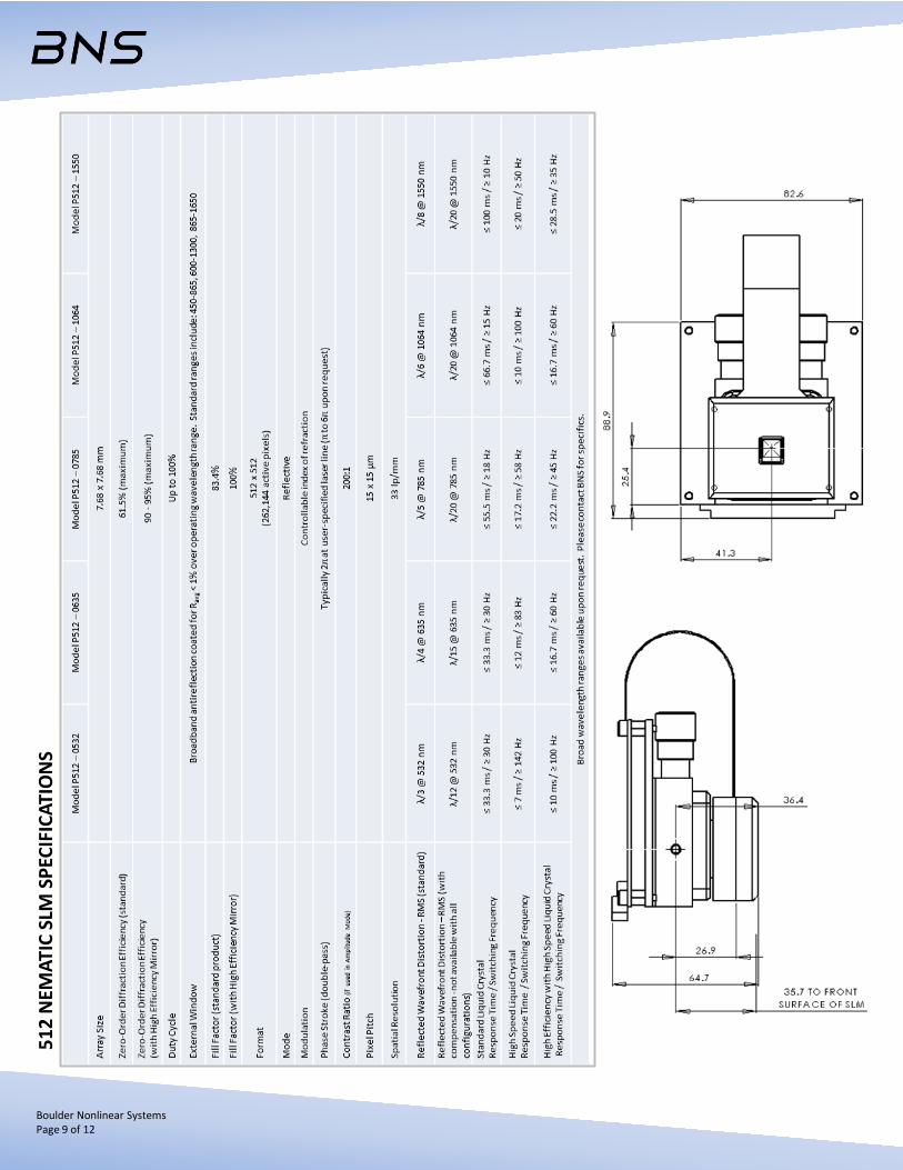
512
NEM
ATIC
SLM
SPE
CIFI
CATI
ON
S
CENTER OF ACTIVE AREA
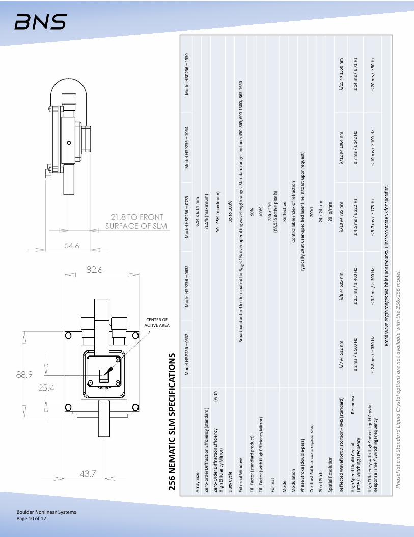
256
NEM
ATIC
SLM
SPE
CIFI
CATI
ON
S
Phas
eFla
t and
Sta
ndar
d Li
quid
Cry
stal
opt
ions
are
not
ava
ilabl
e w
ith th
e 25
6x25
6 m
odel
.
Boulder Nonlinear Systems Page 10 of 12

FLC
SLM
SPE
CIFI
CATI
ON
S
FLC
SLM
s ar
e av
aila
ble
in 5
12x5
12 m
odel
s on
ly.
DRI
VER
SPE
CIFI
CATI
ON
S
Boulder Nonlinear Systems Page 11 of 12
PCIe
8-b
it
PCIe
16-
bit
DV
I
Boulder Nonlinear Systems, Inc. (BNS) is an innovative technology company specializing in dynamic liquid crystal polarization
control solutions for both laser-based and imaging systems. Company strengths in scientific research and development are
leveraged into OEM and standard product offerings target for biomedical, defense, microscopy, optical computing, beamsteering,
telecommunications, wavefront correction and more.
For additional product and company information, please contact:
Boulder Nonlinear Systems, Inc. Telephone: 303-604-0077 450 Courtney Way Toll free: 866-466-0506 Lafayette, Colorado 80026 Fax: 303-604-0066 USA E-mail: [email protected] Website: www.bnonlinear.com
Germany, Austria and Switzerland
Laser 2000 GmbH Argelsrieder Feld 14 82234 Wessling, Germany [email protected] tel: 49 8153 405 0 fax: 49 8153 405 33 web: http://www.laser2000.de Israel
Militram 87 Harav Kook Street Herzliya Israel 46503 [email protected] tel: 972 9 958 1860 fax: 972 9 957 4383 web: http://www.militram.com Netherlands, Belgium and Luxembourg
Laser 2000 BeNeLux C.V Voorbancken 13A 3645 ZJ Vinkeveen, Netherlands [email protected] tel: 31 297 266191 fax: 31 297 266134 web: http://www.laser2000.nl
United Kingdom
Laser 2000 UK Ltd. Britannia House, Ringstead, Denford Road NN144DF Northants, United Kingdom [email protected] tel: 44 1933 461666 fax: 44 1933 461699 web: http://www.laser2000.co.uk Japan
Opto Science, Inc. Naitocho Bldg., 1, Naitocho, Shinjuku-ku, Tokyo 160-0014, Japan [email protected] tel: 81 3 3356 1064 fax: 81 3 3356 3466 web: http://www.optoscience.com China
Aunion Tech Co., Ltd. Room 904 Building 1, No. 1878 West Zhongshan Road Shanghai 200235 China [email protected] tel: 86 21 51083793 fax: 86 21 34241962 web: http://www.haoliangtech.com
Spain and Portugal
Laser 2000, oficina Iberia c/Doctor Palomar 28, 1 A 50002 – Zaragoza, Spain [email protected] tel: 34 976 299 150 fax: 34 976 299 150 web: http://www.laser2000.es France
Laser 2000 SAS Parc d´affaires, 3, rue de la Plaine 78860 Saint-Nom-la-Bretéche, France [email protected] tel: 33 1 3080 0060 fax: 33 1 3080 040 web: http://www.laser2000.fr
World-Wide Distribution