Embed Size (px)
DESCRIPTION
ju
Citation preview
Page 1 sur 62
Toulouse, le 19 Septembre 2003DO/TA - 4159/03Ed.02 du 06/05/2004
ATR 42/72
BORDERAU DE DIFFUSION DE LA
SPECIFICATION TECHNIQUE D'EQUIPEMENT
************************************************************
N° DE SPEC : DO/TA – 4159/03 Ed.02 06/05/2004
DESIGNATION : RECORDING SYSTEM - AIRCRAFT MONITORING SYSTEM
DESCRIPTION : MULTI-PURPOSE COMPUTER (MPC)
************************************************************
DIFFUSION : DO/T C.ORSIDO/TF G.PETITDO/TA D. CLERCDO/TV E.DELESALLEDO/QE F.CAPOVILLADO/PE B.HAAG
Page 2 sur 62
ATR 42 / 72
EQUIPEMENT TECHNICAL SPECIFICATION
************************************************************
N° EQUIP SPEC : DO/TA 4159/03 Ed.02 06/05/2004
SYSTEM : RECORDING SYSTEM – AIRCRAFT MONITORING SYSTEM
EQUIPMENT : MULTI-PURPOSE COMPUTER (MPC)
************************************************************
COMPILED BY : R. TROUILHET APPROVED BY : D. CLERC
P.BERTHELOT G.PETIT
AUTHORIZED BY: C.ORSI
Ce document est CONFIDENTIEL, il est la propriété d’ATR.
Ce document ne peut être, en partie ou en totalité reproduit, ni communiqué à quiquonque, ni utilisé àl'encontre des dites Sociétés.
This document is CONFIDENTIAL, it is the property of ATR.
This document must not be, partially, reproduced, nor lent to a third party, nor used against the aforementioned Companies.
Page 3 sur 62
EQUIPEMENT SPECIFICATION
LIST OF REVISIONS
ISSUE DATE EFFECT ONPAGE PAR
REASON FOR REVISION
1
2
19.09.03
06.05.04
All 1er issue. “Call for tender specification”
2ème Issue
Page 4 sur 62
EQUIPEMENT SPECIFICATION
CURRENT ISSUE OF PAGES
PAGE ISSUE PAGE ISSUE PAGE ISSUE PAGE ISSUE
Page 5 sur 62
INDEX
1. GENERAL
1.1. PURPOSE
1.2. SCOPE
1.3. DATA SUBJECT TO GUARANTEES
1.4. ABBREVIATIONS
1.5. APPLICABLE DOCUMENTS
1.5.1. GENERAL
1.5.2. ATR ATR DOCUMENTS
1.5.2.1. MISCELLANEOUS DOCUMENTS
1.5.2.2. QUALITY REQUIREMENTS DOCUMENTS
1.5.2.3. ARINC DOCUMENTS
1.5.2.4. EUROCAE / FAR AND RTCA DOCUMENTS
1.5.2.5. REGULATION DOCUMENTS
1.5.2.6. COMPANIES DOCUMENTS
1.5.2.7. TECHNICAL REQUIREMENT DOCUMENTS
2. DESIGN REQUIREMENTS AND OPERATING CONDITIONS
2.1. DESCRIPTION
2.1.1. DEFINITIONS, PROVISIONS, DEVELOPMENT SPARES AND GROWTHCAPABILITY
2.1.2. SYSTEM ARCHITECTURE
2.1.3. FUNCTIONS TO BE PERFORMED BY MPC
2.1.3.1 FDAU Part
2.1.3.2 DMU Part
2.1.4. IDENTIFIED PROVISIONS
2.1.4.1. FDAU Part
Page 6 sur 62
2.1.4.2. DMU Part
2.2. CHARACTERISTICS
2.2.1. INTERFACES
2.2.1.1. GENERAL INTERFACE REQUIREMENTS
2.2.1.2. INTERFACE WITH OTHER SYSTEMS OR EQUIPMENTS
2.2.1.3. MECHANICAL INTERFACE
2.2.1.4. HYDRAULIC INTERFACE
2.2.1.5. ELECTRICAL INTERFACE
2.2.1.5.1. Power supply
2.2.1.5.2. Power consumption
2.2.1.5.3. Input / output capacity
2.2.1.5.4. Connection and wiring
2.2.1.5.5. Input/output characteristics and protections
2.2.1.5.6. Circuit breaker characteristics
2.2.1.5.7. Characteristics of signals
2.2.1.6. PNEUMATIC INTERFACE
2.2.2. ERGONOMICS ASPECTS
2.2.2.1. GENERAL
2.2.3. BUILT-IN TEST EQUIPMENT (BITE)
2.2.4. O.B.R.M (ON BOARD REPLACEABLE MODULE)
2.2.5. DATA LOADING
2.2.5.1 GENERAL
2.2.5.2 DATA LOADING METHODOLOGY
2.2.6. INTERCHANGEABILITY
2.2.7. MIXABILITY
2.2.8. NUMBER OF COMPONENTS
2.2.9. LOCKING OF PARTS
2.2.10. BONDING
2.2.11. MISCELLANEOUS DESIGN REQUIREMENTS
Page 7 sur 62
2.3. PERFORMANCE
2.3.1. SYSTEM PERFORMANCE
2.3.2. PERFORMANCE RELATIVE TO POWER CUTS
2.3.3. SYSTEMS RESPONSE TIME
2.3.4. UNIT CAPACITY
2.3.4.1. ADDITIONAL INFORMATION TO DETERMINE THE BASIC UNITCAPACITY
2.3.4.2. PURCHASER DEVELOPMENT SPARES
2.3.4.3. PROCESSING POWER AND MEMORY CAPACITY
2.3.5. GROWTH CAPABILITY
2.4. MATERIALS AND PRODUCTION PROCESSES-CORROSION
2.4.1. GENERAL REQUIREMENTS
2.4.2. FLUIDS AND PRODUCTS USED ON AIRCRAFT
2.4.3. HYDRAULIC FLUID TEMPERATURE
2.4.4. FIRE PROPAGATION
2.4.5. FLAMMABILITY, SMOKE AND TOXIC GAS EMISSION
2.5. LOCATION AND ENVIRONMENT
2.5.1. LOCATION
2.5.2. ENVIRONMENTAL CONDITIONS
2.5.3. HEAT DISSIPATION, VENTILATION, COOLING AND HEATING
2.5.3.1. HEAT DISSIPATION
2.5.3.2. VENTILATION - COOLING
2.6. OPERATIONAL DATA
2.7. INSTALLATION
2.8. NOISE
2.9. MASS
Page 8 sur 62
2.10. VOLUME
2.11. PIN PROGRAMMING
3. SAFETY - RELIABILITY - MAINTAINABILITY
3.1. SAFETY - RELIABILITY
3.1.1. DEFINITION OF TERMS
3.1.2. SAFETY AND RELIABILITY OBJECTIVES
3.1.3. SEGREGATION REQUIREMENTS
3.1.3.1. GENERAL REQUIREMENT
3.1.3.2. PROTECTION AGAINST PHYSICAL DISTURBANCE ON INPUTS /OUTPUTS DEDICATED TO ENGINES
3.1.3.3. CHANNELS SEGREGATION - DISSIMILARITY
3.1.4. SAFETY TESTS
3.1.5. FAILURE ANALYSIS
3.1.5.1. FMEA
3.1.5.2. FMES
3.1.6. HAZARD ANALYSIS
3.1.7. SPECIAL REQUIREMENTS
3.2. RELIABILITY AND MAINTAINABILITY
3.2.1. DEFINITION OF TERMS
3.2.2. RELIABILITY
3.2.3. SERVICE LIFE
3.3. QUALITY ASSURANCE FOR SAFETY AND MAINTAINABILITY
3.4. DEFECT INVESTIGATION ON REJECTED UNIT
4. CERTIFICATION AND QUALIFICATION
4.1. DEFINITION OF TERMS
4.2. REGULATIONS AND CERTIFICATION CONSIDERATIONS
Page 9 sur 62
4.3. QUALIFICATION
4.3.1. GENERAL
4.3.2. UNIT CATEGORY AND CLASSIFICATION
4.3.3. QUALIFICATION DOCUMENTS
4.3.4. MINIMUM QUALIFICATION BEFORE DELIVERY OF THE FIRST UNIT
4.3.5. QUALIFICATION BEFORE FIRST FLIGHT
4.4. CONTINUING AIRWORTHINESS
5. SOFTWARE DEVELOPMENT REQUIREMENTS
5.1. SOFTWARE QUALITY CLAUSES
6. HARDWARE DEVELOPMENT REQUIREMENTS
6.1. DESIGN CAPABILITY EVALUATION OF SUPPLIER
6.2. DESIGN STANDARDS
6.3. HARDWARE TESTABILITY COVERAGE
6.4. SELECTION OF ELECTRONIC COMPONENTS AND ASSEMBLY PROCESSES6.4.1. TECHNOLOGY QUALIFICATION TESTS
6.4.2. TECHNOLOGIES MODIFICATIONS AND REQUALIFICATION
6.5. ELECTRONICS COMPONENTS SCREENING TESTS
6.6. SELECTION OF MATERIALS
6.7. HARDWARE QUALITY CLAUSES
6.8. ASICS QUALITY CLAUSES
7. MANUFACTURING AND TESTS
7.1. MANUFACTURING AND SCREENING
7.1.1. MANUFACTURING
Page 10 sur 62
7.1.2. SCREENING SPECIFICATION
7.2. MANUFACTURING TEST
7.2.1. MANUFACTURING DETAILED TEST SPECIFICATION (DTS)
7.2.2. ACCEPTANCE TEST SPECIFICATION (ATS)
7.2.2.1. ATS DEFINITION
7.2.2.2. ACCEPTANCE TEST AND TEST COVERAGE ANALYSIS APPROVAL
7.2.2.3. TEST COVERAGE REQUIREMENTS
7.2.2.4. MINIMUM ATS CONTENT
7.2.3. ATLAS TEST SPECIFICATION
7.2.4. MAINTENANCE TEST SPECIFICATION (MTS)
7.2.5. ACCEPTANCE TEST DOCUMENTATION DELIVERY
8. QUALITY ASSURANCE
8.1. GENERAL
8.2. QUALITY ASSURANCE PROVISIONS THROUGHOUT THE LIFE CYCLE
9. CONFIGURATION MANAGMENT
9.1. IDENTIFICATION
9.2. CHANGE MANAGEMENT
9.2.1. MODIFICATION WITH SPECIFICATION EVOLUTION (DCR, DCI/EMS)
9.2.2. MODIFICATIONS OF THE UNIT TO SATISFY THE TECHNICALSPECIFICATION
9.2.3. OTHER MODIFICATIONS
9.2.4. SOFTWARE CHANGE IMPLEMENTATION
9.2.5. CHANGE DOCUMENTATION
10. METHOD AND TOOLS
11. TECHNICAL RESPONSIBILITIES ORGANIZATION
11.1. PURCHASER AND SUPPLIER TECHNICAL RESPONSIBILITIES

Page 11 sur 62
11.1.1. GENERAL
11.1.2. PROVISIONS AND DEVELOPMENT SPARES RESPONSIBILITIES
11.1.3. SOFTWARE RESPONSIBILITY
11.1.3.1. SUPPLIER RESPONSIBILITIES
11.1.3.2. PURCHASER RESPONSIBILITIES
11.2. DEVELOPMENT PHASES
11.3. ORGANIZATION - INTEGRATED TEAMS
12. PROJECT MANAGEMENT
12.1. PROGRESS MEETINGS
12.2. TECHNICAL MEETINGS12.3. MANAGEMENT MEETINGS
12.4. REVIEW MEETINGS
12.4.1. REVIEWS LIST
12.4.2. PLANS REVIEW (PR)
12.4.3. PRELIMINARY DESIGN REVIEW (PDR)
12.4.4. CRITICAL DESIGN REVIEW (CDR)
12.4.5. LABORATORY UNIT ACCEPTANCE (LUA)
12.4.6. FIRST FLIGHT ARTICLE REVIEW (FFAR)
12.4.7. CERTIFICATION FIRST ARTICLE REVIEW (CFAR)
12.5. PERFORMANCES ASSESSMENT
12.6. AUDITS
13. STORAGE AND HANDLING
14. SUPPLYING
14.1. DELIVERY STANDARD FOR DEVELOPMENT PHASES

Page 12 sur 62
14.2. TECHNICAL DATA / DOCUMENTATION
14.2.1. GENERAL
14.2.2. SUPPLIER'S TECHNICAL PROPOSAL
14.2.2.1. CONTENTS
14.2.2.2. REQUIRED PROPOSAL PLAN AND FORM
14.2.3. EQUIPMENT DOCUMENTS
14.2.4. SOFTWARE DOCUMENTATION
15. DEVELOPMENT SCHEDULE
Page 13 sur 62
APPENDIX
APPENDIX 1
Aircraft Performances Monitoring Function DO/TF 2049/04 Ed.01
APPENDIX 2
Enhanced Surveillance & ADS-B Function DO/TY 3166/04 Ed.01
APPENDIX 3
AFCS Maintenance Function DO/TY 3167/04 Ed.01
APPENDIX 4
TCAS Maintenance Function DO/TY 3168/04 Ed.01
APPENDIX 5
MFC Maintenance Maintenance Memory ReadingFunction DO/TY 3169/04 Ed.01
APPENDIX 6
Radio Communication / Navigation Maintenance Function DO/TY 3170/04 Ed.01
APPENDIX 7
G-Meter Function DO/TY 3171/04 Ed.01
APPENDIX 8
PEC / EEC Maintenance Function DO/TY 3172/04 Ed.01
Page 14 sur 62
AATTRR 4422 // 7722
RREECCOORRDDIINNGG SSYYSSTTEEMM -- AIRCRAFT MONITORING SYSTEM
1. GENERAL
1.1. PURPOSE
This technical document defines the specification for the “Multi-Purpose Computer (MPC).The role and functions of this computer are described in chapter 2 of this specification.It defines :- the technical requirements the system must satisfy,- the installation characteristics for these items,- the environmental conditions,- the requested documentation.
The supplier shall be entirely responsible contractually for the fulfillment of these requirements.In no case has the supplier proposal any contractual authority.
1.2. SCOPE
This technical document deals with the "MPC” used on all ATR aircraft.
The hardware shall be identical for all type of aircraft.The embedded software :- shall have the capability to be uploaded,- shall be identical for both aircraft, including pin-programmable functions dedicated to specific
applications, if necessary.
1.3. DATA SUBJECT TO GUARANTEES
The technical specification clearly identifies the data subject to guarantees from the supplier.The guaranteed data shall be :- sizes,- weight,- heat dissipation,- electrical consumption,- MTBF,- MTBUR,- service life,- computation performances,- safety objectives.
All the technical data required in this document shall be guaranteed by the supplier.
1.4. ABBREVIATIONS
A/C : AircraftACARS : Aircraft Communications Addressing and Reporting SystemACMS : Airplane Condition Monitoring SystemADL : Airborne Data Loader
Page 15 sur 62
MPC : Multi Purpose ComputerAFDAU : Auxiliary Flight Data Acquisition UnitAIDS : Aircraft Integrated Data SystemARINC : Aeronautical Radio IncBITE : Built In Test EquipmentCSDB : Commercial Standard Digital BusCVR : Cockpit Voice RecorderDFDR : Digital Flight Data RecorderDMT : Display Memory TerminalDMU : Data Management UnitFDAU : Flight Data Acquisition UnitFMEA : Failure Modes Effects AnalysisFMES : Failure Modes Effects SummaryI/O : Input / OutputJAA : Joint Aviation AuthoritiesLRU : Line Replaceable UnitMCDU : Multipurpose Control and Display UnitMPTR : Multipurpose PrinterMTBF : Mean Time between FailuresMTBUR : Mean Time between Unscheduled RemovalsNA : Not ApplicablePC : Personal ComputerPCM : Pulse Code ModulationPCMCIA : Personal Computer Memory Card International AssociationPDL : Portable Data LoaderPTE : Portable Test EquipmentP/N : Part NumberQAR : Quick Access RecorderSSM : Sign & Status MatrixTBA : To Be Answered (by the supplier before the selection)TBC : To Be Confirmed (by the purchaser before the selection and accepted by the supplier)TBD : To Be Defined (by the purchaser before the selection and accepted by the supplier).
1.5. APPLICABLE DOCUMENTS
1.5.1. GENERAL
Unless otherwise specified, the units shall comply with the documents listed hereafter andwith applicable documents referenced in them.
1.5.2. ATR ATR DOCUMENTS
1.5.2.1. MISCELLANEOUS DOCUMENTSNote D00S-322-4001C : Characteristics of ATR 42 electrical generation,MIL-HDBK 217E : Reliability prediction of electronic equipment.Note AS 419.066/82 ATR 42 General Equipment Environmental ConditionsNote AS 419.065/82 ATR 42 General Technical Requirement of Equipment
1.5.2.2. QUALITY REQUIREMENTS DOCUMENTSD-74.01 Supplier Quality Requirements.CG.0084 Suppliers Survey.CG.0073 Suppliers Qualification.M011 Industrial Process Control Evaluation
1.5.2.3. ARINC DOCUMENTSARINC 724B : Aircraft Communication Addressing and Reporting System
(ACARS),ARINC 573 : Aircraft Integrated Data System (AIDS Mark 2),ARINC 429 : Mark 33 Digital Information Transfer System,

Page 16 sur 62
ARINC 600 : Air transports Avionics Equipment Interfaces,ARINC 615-3 : Data Loading,ARINC 739 : Multi purpose Control and Display Unit,ARINC 591 : Quick Access Recorder for AIDS System,ARINC 717 : Flight Data Acquisition and Recording System,ARINC 597 : Communications Addressing and Reporting System.ARINC 615 : Airborne Computer – High Speed Data LoaderARINC 740/744 : Multiple-input Cockpit Printer
1.5.2.4. EUROCAE / FAR AND RTCA DOCUMENTSEUROCAE ED 14 / RTCA DO160 : Environmental Conditions and Tests
Procedures for Airborne Equipment.EUROCAE ED 12 / RTCA D0178 : Software Considerations in Airborne
Systems and equipment Certification.EUROCAE ED 80 / RTCA D0254: Design assurance guidance for airborne
Electronic hardware.
1.5.2.5. REGULATION DOCUMENTSEUROCAE ED 55,FAR 121-344,FAR 25,JAR 25.
1.5.2.6. COMPANIES DOCUMENTS523-0772774-00911R Ed 9 January 14 1998 : Commercial Standard Digital Bus
(CSDB).EB 7013343 : Avionics Standard Communication Bus (ASCB) Version A.
1.5.2.7 TECHNICAL REQUIREMENT DOCUMENTSD-75.03 Identification marking of aircraft items.CG-0163 FEE / DDP processing and distribution.
Page 17 sur 62
2. DESIGN REQUIREMENTS AND OPERATING CONDITIONS
2.1. DESCRIPTION
2.1.1. DEFINITIONS, PROVISIONS, DEVELOPMENT SPARES AND GROWTHCAPABILITY
Basic functions and basic definition :All the functions required in this document, which are not provision are called basicfunctions.Basic functions and their associated requirements define the basic definition.
Identified provisions :Different levels of identified provisions are used according :- to the knowledge of the function with which the provision is associated,- to the probability of implementation of the function in the unit.
There are three types of identified provisions :
1) Space provision :In order to make space provision for a function within a unit, the supplier shall ensurethat :- the overall size of the unit and the size of any associated panel or display for which
the supplier has responsibility are compatible with the inclusion of the function- the size of any electronic card or assembly that is contained within the unit can
accommodate the necessary additional Input/Output, memory and processing capacityneeded to implement the function.
2) System provisionIn order to make system provision for a function within a unit the supplier shall ensurethat :- space provision is made,- all mechanical subassemblies and associated wiring to perform the function are
included in the unit (e.g. switches, controls, and connectors),- on the electronic cards the circuits and associated wiring to accomplish the
input/output task associated with the function are included,- the memories installed in the unit are sufficient to meet the memory needs of the
function,- the processing requirement of the function can be met within the installed processing
capacity of the unit,- the software implementing the basic definition shall be designed to allow an easy
addition of the function (without modification to the software architecture).3) Full provision
In order to make full provision for a function within a unit, the supplier shall ensurethat :- the function is treated as a basic function (as such, it is implemented within the unit).
Identified definition :The basic definition plus the identified provision constitute the identified definition.
Supplier development spares :The supplier may take supplier development spares in order to face his possible errors, forinstance :
Page 18 sur 62
- when defining the characteristics of the unit he considers necessary for the identifieddefinition,
- when developing the unit,- .... .
Basic Unit capacity :The - basic definition,
- identified provisions,- supplier development spares,- and the associated requirements (required performance, for instance), allow the
supplier to define the basic unit capacity.
Growth capability :The growth capability is constituted by the extra provisions, which could be defined by thesupplier in order to ease future development for functions, which are not defined in thepresent document.
Options :An option constitutes an extension of the basic aircraft.It is taken into account in this technical specification either through the basic functions, orthrough the identified provision.The word "option" is reserved for the aircraft system.
2.1.2. SYSTEM ARCHITECTURE
The general architecture of the system is shown on figure1.The MPC includes the following inputs/outputs :- interface from aircraft to MPC,- interface from MPC to aircraft.The organization retained shall enable to accomplish the specified functions in compliancewith the requirements specified including safety objectives and system growth capability.
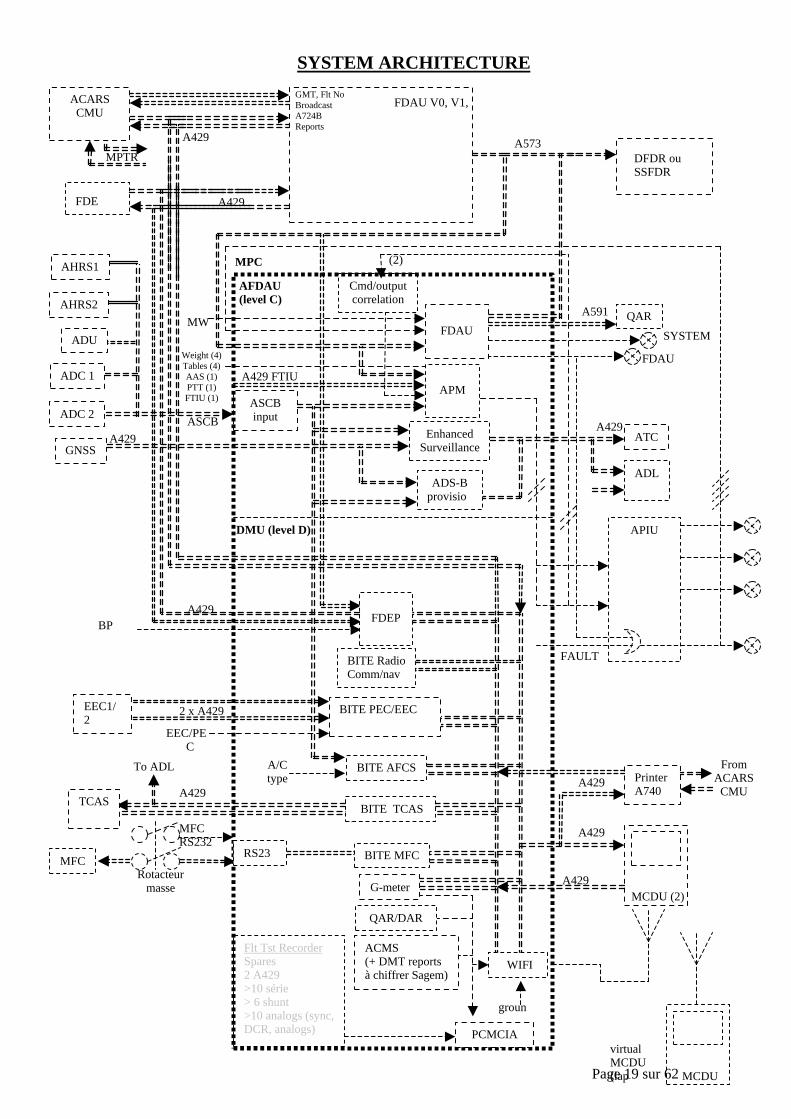
Page 19 sur 62
SYSTEM ARCHITECTURE
FDAU V0, V1,V2
DFDR ouSSFDR
FDEP
MPC
AFDAU(level C)
DMU (level D)
ASCBinput
PCMCIA
ATC
PrinterA740
G-meter
A429
A429
ASCBA429
A429
A573
A429
A429
A429
A429
QARA591
MFC
WIFI
ground
virtualMCDU(laptop)
A/Ctype
BPEVENT
BITE AFCS
FDEP
BITE TCAS
QAR/DAR
BITE MFC
BITE RadioComm/nav
RS232
2 x A429
Rotacteurmasse
ADS-Bprovisio
n
EnhancedSurveillance
A429
MFCRS232ON
APIU
Cmd/outputcorrelation
FAULT
SYSTEM
FDAU
ADL
FDAU
ADC 1
ADC 2
GNSS
AHRS1
AHRS2
ADU
EEC1/2PEC1/2
TCAS
BITE PEC/EEC
ACMS(+ DMT reportsà chiffrer Sagem)
MCDU (2)
FromACARS
CMU
EEC/PECsel
Weight (4)Tables (4)AAS (1)PTT (1)FTIU (1)
MW
(2)
MCDU
APMA429 FTIU
Flt Tst RecorderSpares2 A429>10 série> 6 shunt>10 analogs (sync,DCR, analogs)
GMT, Flt NoBroadcastA724BReports
MPTR
ACARSCMU
To ADL
Page 20 sur 62
2.1.3. FUNCTIONS TO BE PERFORMED BY THE MPC
The MPC shall accomplish the following functions :
2.1.3.1 FDAU Part
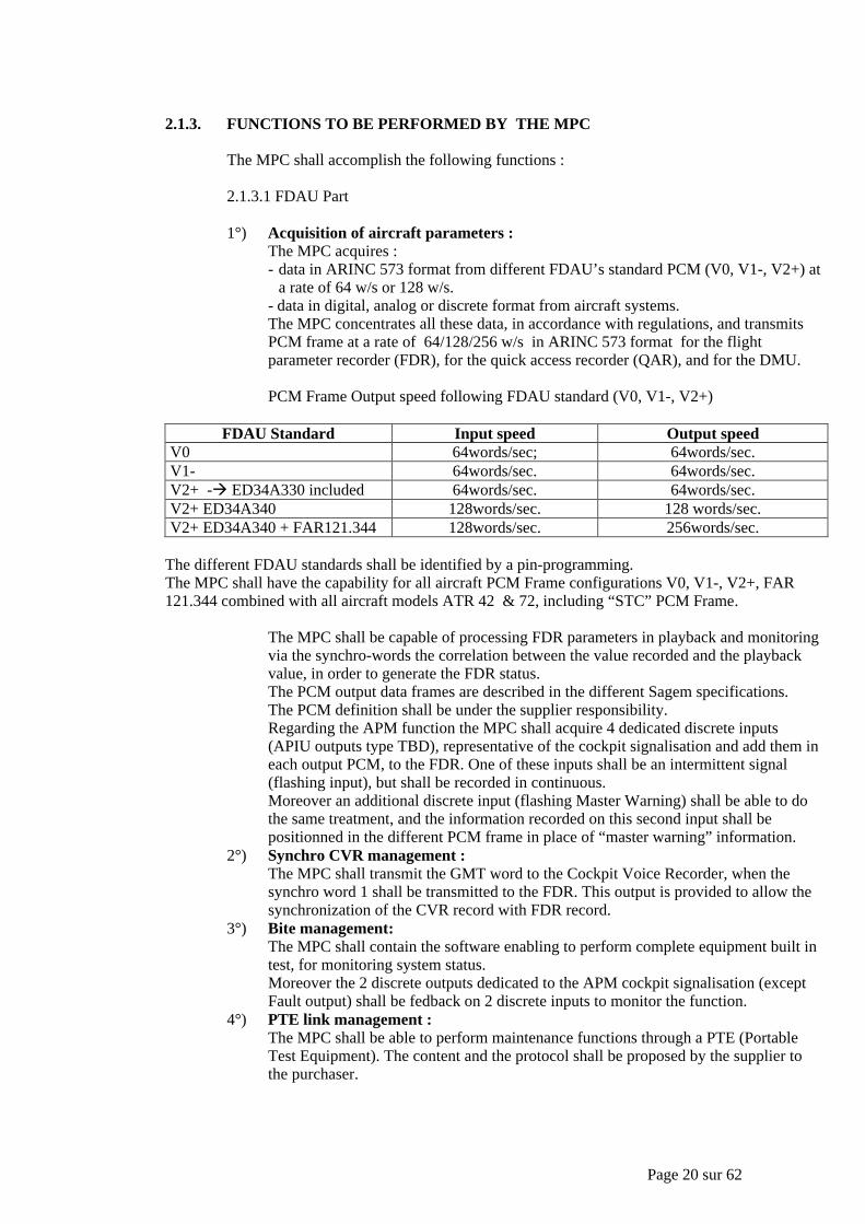
1°) Acquisition of aircraft parameters :The MPC acquires :- data in ARINC 573 format from different FDAU’s standard PCM (V0, V1-, V2+) at
a rate of 64 w/s or 128 w/s.- data in digital, analog or discrete format from aircraft systems.The MPC concentrates all these data, in accordance with regulations, and transmitsPCM frame at a rate of 64/128/256 w/s in ARINC 573 format for the flightparameter recorder (FDR), for the quick access recorder (QAR), and for the DMU.
PCM Frame Output speed following FDAU standard (V0, V1-, V2+)
FDAU Standard Input speed Output speedV0 64words/sec; 64words/sec.V1- 64words/sec. 64words/sec.V2+ -à ED34A330 included 64words/sec. 64words/sec.V2+ ED34A340 128words/sec. 128 words/sec.V2+ ED34A340 + FAR121.344 128words/sec. 256words/sec.
The different FDAU standards shall be identified by a pin-programming.The MPC shall have the capability for all aircraft PCM Frame configurations V0, V1-, V2+, FAR121.344 combined with all aircraft models ATR 42 & 72, including “STC” PCM Frame.
The MPC shall be capable of processing FDR parameters in playback and monitoringvia the synchro-words the correlation between the value recorded and the playbackvalue, in order to generate the FDR status.The PCM output data frames are described in the different Sagem specifications.The PCM definition shall be under the supplier responsibility.Regarding the APM function the MPC shall acquire 4 dedicated discrete inputs(APIU outputs type TBD), representative of the cockpit signalisation and add them ineach output PCM, to the FDR. One of these inputs shall be an intermittent signal(flashing input), but shall be recorded in continuous.Moreover an additional discrete input (flashing Master Warning) shall be able to dothe same treatment, and the information recorded on this second input shall bepositionned in the different PCM frame in place of “master warning” information.
2°) Synchro CVR management :The MPC shall transmit the GMT word to the Cockpit Voice Recorder, when thesynchro word 1 shall be transmitted to the FDR. This output is provided to allow thesynchronization of the CVR record with FDR record.
3°) Bite management:The MPC shall contain the software enabling to perform complete equipment built intest, for monitoring system status.Moreover the 2 discrete outputs dedicated to the APM cockpit signalisation (exceptFault output) shall be fedback on 2 discrete inputs to monitor the function.
4°) PTE link management :The MPC shall be able to perform maintenance functions through a PTE (PortableTest Equipment). The content and the protocol shall be proposed by the supplier tothe purchaser.
Page 21 sur 62
5°) ADL interfaceTwo Arinc 429 lines (one input and one output) and activation discretes shall beprovided to upload software from the ADL/PDL to the AFDAU (Arinc 615-3).
6°) DMU outputOne Arinc 429 bus and asynchronous HDLC line shall be provided to transmit datainternally from the AFDAU to the DMU (the Arinc 429 bus is also external to theMPC).
7°) Discrete outputsThe AFDAU shall provide AFDAU and APM Fail & FDRS Fail outputs (AFDAUfail: steady output, APM fail: flashing output)
8°) Enhanced surveillance & ADS-BThe Enhanced Surveillance and the ADS-B, through acquisition of specificparameters from aircraft computers shall enable the air traffic controller to increaseefficiency in tactically separating aircraft.This function shall be realized with a software DO 178B level C.Detailed information regarding this function shall be given in a dedicated appendix.
9°) Aircraft Performances MonitoringThis function, through acquisition of specific parameters shall enable the monitoringof aircraft performances.This function shall be realized with a software DO 178B level C.Detailed information regarding this function shall be given in a dedicated appendix .
2.1.3.2 DMU Part
1°) MCDU’s interfaceThree Arinc 429 buses (two inputs and one output) shall be provided to manage adialogue with two MCDU’s Arinc 739.Output to MCDUs will be shared with MPTR.
2°) G-Meter functionThis function, through acquisition of specific parameters, shall enable the display, atthe end of the flight, to the crew, of the vertical acceleration value in flight and at thelanding.This function shall be realized with a software DO 178B level D.This function shall be treated as an ACMS standard report.This function shall be available with all FDAU standard versions.Detailed information regarding this function shall be given in a dedicated appendix .
3°) Maintenance function (software DO 178B level D) – see appendixa) TCASb) AFCSc) MFCd) PEC/EEC – bite and trime) rad com/rad navDetailed information regarding this function shall be given in dedicated appendix .
4°) FDEP interfaceThis function shall enable to remove FDEP equipment from aircraft and to replacedthis item by MCDU associated to dedicated menus.This function shall be compatible with all FDAU standards (V0, V1-, V2+)The supplier shall provide the purchaser with a protocol proposition, for agreement.All the functions realized by FDEP/FDAU interface shall be insure by means ofMPC/MCDU interface.Two Arinc 429 lines (one input and one output) shall be provided.Output will be shared with TCAS.
5°) PCMCIA interfaceA PCMCIA interface shall be provided allowing to accept removable type I and IImedia. This PCMCIA shall be used for the internal QAR/DAR/G-meter reportsfunctions.
6°) ADL interface
Page 22 sur 62
Two Arinc 429 lines (one input and one output and a dedicated activation discrete)shall be provided to upload software and download data from the ADL/PDL to theDMU (Arinc 615-3).
7°) A full duplex asynchronous link shall be provided to connect the DMU to a PC basedPortable Test Equipment (PTE).
8°) Discrete outputsThe DMU shall provide 3 discrete outputs.
9°) RS 232 inputThis input shall be used for PTE or for MFC Bite acquisition via an external selectorswitch with dedicated selection pin programThe description of this MFC Bite function shall be described in dedicated appendix.
2.1.5. IDENTIFIED PROVISIONS
All the following identified provisions shall be available in the definition of MPC.
2.1.5.1 QAR output (Arinc 591)The QAR RZ Bipolar output shall send the same PCM frame as FDR PCM framewith a synchronization pulse generated at the end of each on the QAR synchro outputThe same data frame as FDR output one is sent to the QAR. Only the coding isdifferent, it is a RZ Bipolar code. Moreover a QAR synchro output is provided forsynchro pulse generation.
2.1.5.2 MPTR interfaceTwo Arinc 429 buses (one input and one output) shall be provided to manage adialogue with a MPTR , following Arinc 740 or 744 protocol.Output bus is shared with MCDUs
2.1.5.3 Interface with ACARS :Two Arinc 429 buses (one input and one output) shall be provided to transfer/receivedata to/from ACARS (Arinc 724B).
2.1.5.4 WifiThis function is developped under Sagem responsibility.
2.2. CHARACTERISTICS
2.2.1. INTERFACES
2.2.1.1. GENERAL INTERFACE REQUIREMENTSAll interface aspects not defined in this document shall be submitted to thepurchaser for approval.
2.2.1.2. INTERFACE WITH OTHER SYSTEMS OR EQUIPMENTSDue to his function the MPC shall interface with different aircraft systems.Each type of interface shall be in accordance with :- Arinc standards defined in §.1.5.2,- electrical characteristics of inputs/outputs defined in §2.2.1.5.5.
2.2.1.3. MECHANICAL INTERFACEThe dimensions, attaches, cooling, etc... of the MPC shall comply with ARINC600 specification.
2.2.1.4. HYDRAULIC INTERFACEN.A.
2.2.1.5. ELECTRICAL INTERFACE
Page 23 sur 62
2.2.1.5.1. Power supplyThe power supply characteristics are given in note DOOS-322-4001C.The unit shall comply with it.
2.2.1.5.2. Power consumptionThe MPC maximum consumption shall be : 40W
2.2.1.5.3. Input / output capacity
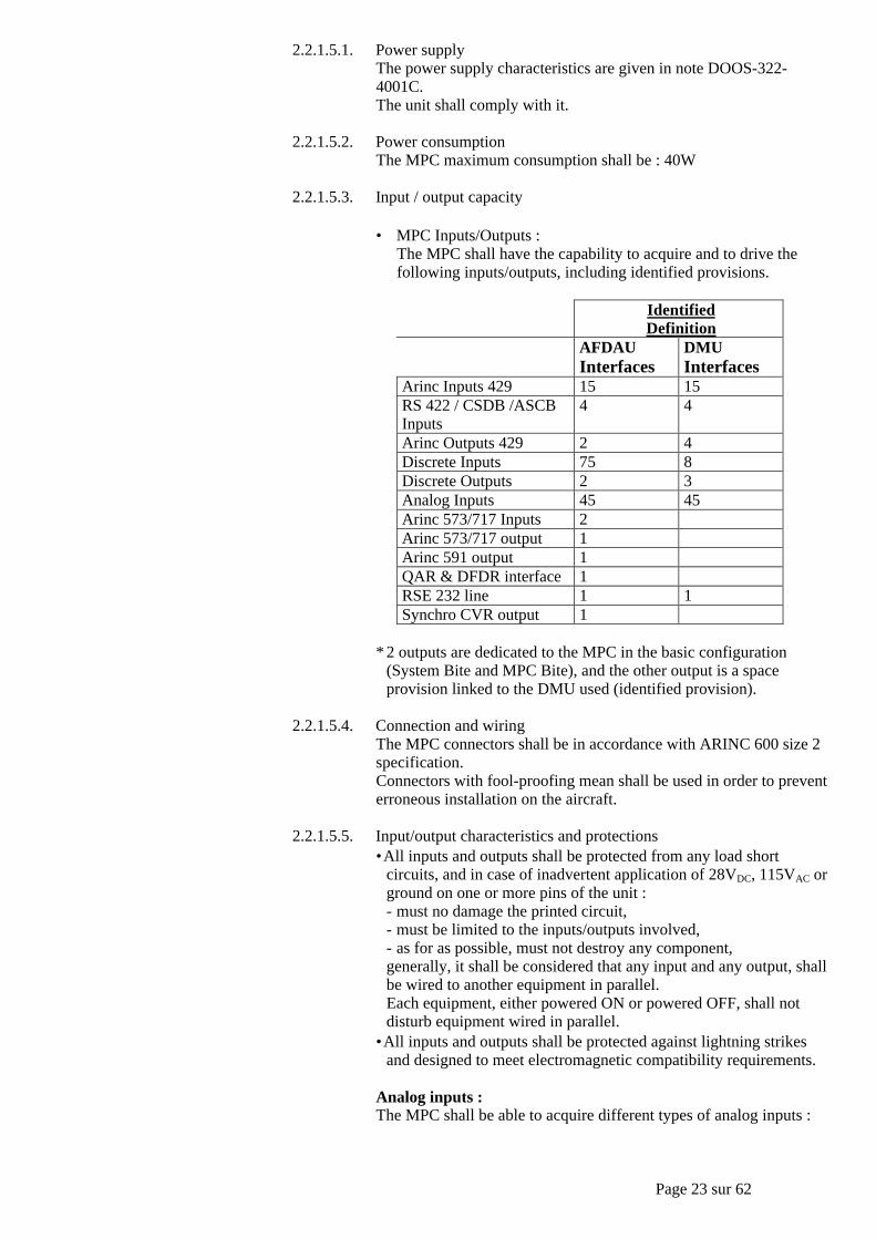
• MPC Inputs/Outputs :The MPC shall have the capability to acquire and to drive thefollowing inputs/outputs, including identified provisions.
IdentifiedDefinition
AFDAUInterfaces
DMUInterfaces
Arinc Inputs 429 15 15RS 422 / CSDB /ASCBInputs
4 4
Arinc Outputs 429 2 4Discrete Inputs 75 8Discrete Outputs 2 3Analog Inputs 45 45Arinc 573/717 Inputs 2Arinc 573/717 output 1Arinc 591 output 1QAR & DFDR interface 1RSE 232 line 1 1Synchro CVR output 1
* 2 outputs are dedicated to the MPC in the basic configuration(System Bite and MPC Bite), and the other output is a spaceprovision linked to the DMU used (identified provision).
2.2.1.5.4. Connection and wiringThe MPC connectors shall be in accordance with ARINC 600 size 2specification.Connectors with fool-proofing mean shall be used in order to preventerroneous installation on the aircraft.
2.2.1.5.5. Input/output characteristics and protections•All inputs and outputs shall be protected from any load short
circuits, and in case of inadvertent application of 28VDC, 115VAC orground on one or more pins of the unit :- must no damage the printed circuit,- must be limited to the inputs/outputs involved,- as for as possible, must not destroy any component,generally, it shall be considered that any input and any output, shallbe wired to another equipment in parallel.Each equipment, either powered ON or powered OFF, shall notdisturb equipment wired in parallel.
•All inputs and outputs shall be protected against lightning strikesand designed to meet electromagnetic compatibility requirements.
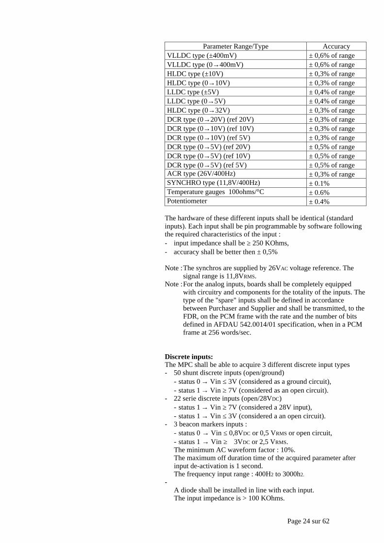
Analog inputs :The MPC shall be able to acquire different types of analog inputs :
Page 24 sur 62
Parameter Range/Type AccuracyVLLDC type (±400mV) ± 0,6% of rangeVLLDC type (0→400mV) ± 0,6% of rangeHLDC type (±10V) ± 0,3% of rangeHLDC type (0→10V) ± 0,3% of rangeLLDC type (±5V) ± 0,4% of rangeLLDC type (0→5V) ± 0,4% of rangeHLDC type (0→32V) ± 0,3% of rangeDCR type (0→20V) (ref 20V) ± 0,3% of rangeDCR type (0→10V) (ref 10V) ± 0,3% of rangeDCR type (0→10V) (ref 5V) ± 0,3% of rangeDCR type (0→5V) (ref 20V) ± 0,5% of rangeDCR type (0→5V) (ref 10V) ± 0,5% of rangeDCR type (0→5V) (ref 5V) ± 0,5% of rangeACR type (26V/400Hz) ± 0,3% of rangeSYNCHRO type (11,8V/400Hz) ± 0.1%Temperature gauges 100ohms/°C ± 0.6%Potentiometer ± 0.4%
The hardware of these different inputs shall be identical (standardinputs). Each input shall be pin programmable by software followingthe required characteristics of the input :- input impedance shall be ≥ 250 KOhms,- accuracy shall be better then ± 0,5%
Note :The synchros are supplied by 26VAC voltage reference. Thesignal range is 11,8VRMS.
Note :For the analog inputs, boards shall be completely equippedwith circuitry and components for the totality of the inputs. Thetype of the "spare" inputs shall be defined in accordancebetween Purchaser and Supplier and shall be transmitted, to theFDR, on the PCM frame with the rate and the number of bitsdefined in AFDAU 542.0014/01 specification, when in a PCMframe at 256 words/sec.
Discrete inputs:The MPC shall be able to acquire 3 different discrete input types- 50 shunt discrete inputs (open/ground)
- status 0 → Vin ≤ 3V (considered as a ground circuit),- status 1 → Vin ≥ 7V (considered as an open circuit).
- 22 serie discrete inputs (open/28VDC)- status 1 → Vin ≥ 7V (considered a 28V input),- status 1 → Vin ≤ 3V (considered a an open circuit).
- 3 beacon markers inputs :- status 0 → Vin ≤ 0,8VDC or 0,5 VRMS or open circuit,- status 1 → Vin ≥ 3VDC or 2,5 VRMS.The minimum AC waveform factor : 10%.The maximum off duration time of the acquired parameter afterinput de-activation is 1 second.The frequency input range : 400H2 to 3000h2.
-A diode shall be installed in line with each input.The input impedance is > 100 KOhms.
Page 25 sur 62
Discrete outputs :The total number of discrete outputs is 5. These outputs are used fordifferent “fault / status” displays.These discrete outputs shall be protected:- against any load shortening,- against lightning strikes.A diode shall be installed in line with each output in the unit.The types of discrete outputs shall be 28VDC / series / shunt circuit.Note :For the discrete inputs and outputs, boards shall be completely
equipped with circuitry and components for the totality of theinputs/outputs.
And except specific definition all the inputs/outputs in "spare" shallbe on the DFDR PCM frame output with a rate of 1pps, whenin a PCM frame at 256 words/sec.
Digital inputs : (see table 2.2.1.5.3)The computer shall be able to receive :- Arinc 429 high or low speed.
The acquisition system shall be designed in order to avoid any lostmessage even if they are arriving simultaneously at the maximumfrequency. Each label used by the MPC shall pass a validity test,on the data except for the discrete words, the refreshmentfrequency, the SSM and the parity shall be also monitored.
- CSDB which are specific acquisitions, compatible with RS422standard and with the Collin's specification (3 of these inputs shallbe hardwired on the electronic card,
- ASCB which is specific acquisitions, following the Honeywellspecification.
- Arinc 573/717 inputs.
Digital outputs : (see table 2.2.1.5.3)The computer shall be able to transmit :- Arinc 429 high speed or low speed,- Arinc 573/717 output,- Synchro CVR output,- QAR & DFDR interface.A short circuit on one output shall not affect any other outputs.
Sensor Power :- different 5VDC/200mA outputs for potentiometer power,- 28VDC output for accelerometer power.
Maintenance interface :- RS 232C bi-directional interface with PTE (test connector).
(one for AFDAU part, one for DMU part)Digital Interfaces- ARINC 429 interface with ARINC 739 MCDU,- ARINC 429 interface with ARINC 744 multi-printer,- ARINC 429 interface with ARINC 724/724B ACARS,- ARINC 429 interface with ARINC 615 ADL,
(one for AFDAU part, one for DMU part)
2.2.1.5.6. Circuit breaker characteristicsN.A.
2.2.1.5.7. Characteristics of signalsThe characteristics of the various signals received by the unit shall begiven in :- specific appendix linked to the different functions
Page 26 sur 62
- AFDAU specification 542.0014/01- Different FDAU standards PCM frames (V0, V1-, V2+)- Spare definition for analog and discrete inputs.
2.2.1.6. PNEUMATIC INTERFACE
N.A.
2.2.2. ERGONOMICS ASPECTS
2.2.2.1. GENERALN.A.
2.2.3. BUILT-IN TEST EQUIPMENT (BITE)
The MPC shall perform permanent, periodic, power-up and maintenance tests :- to guarantee the proper function of the MPC itself,- to aid in trouble shooting of the system.The computer shall store in a non-volatile device the failure of the system and shall transmitthose information to a test equipment.The content of each test shall be defined by the supplier.This test equipment shall be used for :- bite and maintenance word information display (real time and history),- real time display of system inputs/outputs (Arinc 717 inputs/outputs
analog/discrete/digital parameters),- up/down loading.The built in test results control the MPC status output.The breakdown of maintenance word shall be described by the supplier.The BITE data shall be presented on the DFDR PCM Frame. Moreover all detailed faultsshall be stored in non volatile memory and can be displayed by MCDU for DMU faults andby PTE for AFDAU faults.
2.2.4. O.B.R.M (ON BOARD REPLACEABLE MODULE)
N.A.
2.2.5. DATA LOADING
2.2.5.1 GENERALThe data loading shall be considered only as a possibility to change the MPC software.When a software evolution shall be necessary, the airlines shall choose between using thedata loading or the installation of a new MPC already loaded with the correct software.
2.2.5.2 DATA LOADING METHODOLOGYThe MPC in its basic configuration shall have the capability to up load the computersoftware, (and to download AIDS and maintenance data on the DMU part).The data loading shall be achieved by mean of a PDL/ADL and the protocol is defined bythe ARINC 615. The data loading shall also be achieved by mean of a PCMCIA card.This function shall be available on the front panel connector, as well as on the rear panelconnector.The Supplier shall take caution to insure a correct data loading.The data loading result shall be displayed on aircraft by a specific mean different of the toolused for the data loading itself.The data loading identification shall be made by replacement of the software data plate onthe MPC.
2.2.6. INTERCHANGEABILITY
Page 27 sur 62
All units having the same supplier's part number shall be directly and fully interchangeablewith respect to the performance of the unit, and the aircraft installation, without the need forany adjustment.
2.2.7. MIXABILITY
N.A.
2.2.8. NUMBER OF COMPONENTS
N.A.
2.2.9. LOCKING OF PARTS
N.A.
2.2.10. GROUNDING AND BONDING
Bonding shall be achieve by specific wire :- case to mechanical pin resistance ≤ 30m O,- front face to rear face resistance ≤ 25m O- Insulation resistance >= 100Mohms under 50Vdc.- Dielectric strengh : 500V/50Hz.
2.2.11. MISCELLANEOUS DESIGN REQUIREMENTS
N.A.
2.3. PERFORMANCE
2.3.1. SYSTEM PERFORMANCE
N.A.
2.3.2. PERFORMANCE RELATIVE TO POWER CUTS
The unit shall comply with requirement of the note n° DOOS-322-4001C.The supplier shall describe precisely the operation of the computer during the transient untilthe recovery of the correct voltage :• Transient shorter than 200ms :
- No effect on the operation of the computer.• Longer interruption of power (>200ms) :
The MPC shall perform :- A rapid initialization (less then 1 second),- After initialization the PCM frame shall start at the next recognized SYNC word
received from the FDAU input, and the frame counter shall be reset.The supplier shall specified the time at the end of which the computer operate normallyin both cases.
2.3.3. SYSTEMS RESPONSE TIME
N.A.
2.3.4. UNIT CAPACITY
Page 28 sur 62
Purchaser and supplier responsibilities related to the basic and full capacities are describedin §11.1 "purchaser and supplier technical responsibilities".
2.3.4.1. ADDITIONAL INFORMATION TO DETERMINE THE BASIC UNITCAPACITY
N.A.
2.3.4.2. PURCHASER DEVELOPMENT SPARES
Purchaser development spares are required in addition to the "basic unitcapacity" :• processing power :
CPU occupation → TBC by Sagem• memory capacity :
- boot memory → TBC by Sagem,- RAM memory → TBC by Sagem.The MPC shall have the capability for all aircraft PCM Frame configurationsV0, V1-, V2+, FAR 121.344 combined with all aircraft models ATR 42 & 72,including “STC” PCM Frame plus some spare capacity TBC by Sagem
2.3.4.3. PROCESSING POWER AND MEMORY CAPACITY
The supplier shall give the following estimates memory size and processing powerof the unit, detailing the parts dedicated to :- the "basic definition",- the "full provisions",- the "system provisions",- the "space provisions",- the "supplier development spares",- the "purchaser development spares".Detailed description and justification to support the estimated shall be given bythe supplier in his proposal.
2.3.5. GROWTH CAPABILITY
The growth capability concerns the extra capacity : ACMS function.
2.4. MATERIALS AND PRODUCTION PROCESSES-CORROSION
2.4.1. GENERAL REQUIREMENTS
N.A.
2.4.2. FLUIDS AND PRODUCTS USED ON AIRCRAFT
Where applicable, suitable protection shall be provided for the unit
MPCFuels Not applicableHydraulic fluid Not applicableOils Not applicableGreases Not applicableLubricant Not applicableAnti and de-icing agents Not applicable
Page 29 sur 62
Cleaning agents ApplicableDrinks Not applicableWater, Waste Not applicable
2.4.3. HYDRAULIC FLUID TEMPERATURE
N.A.
2.4.4. FIRE PROPAGATION
N.A.
2.4.5. FLAMMABILITY, SMOKE AND TOXIC GAS EMISSION
Components which emit smoke and toxic gases shall be avoided.
2.5. LOCATION AND ENVIRONMENT
2.5.1. LOCATION
The MPC shall be installed in pressurized area, in the electronic bay.
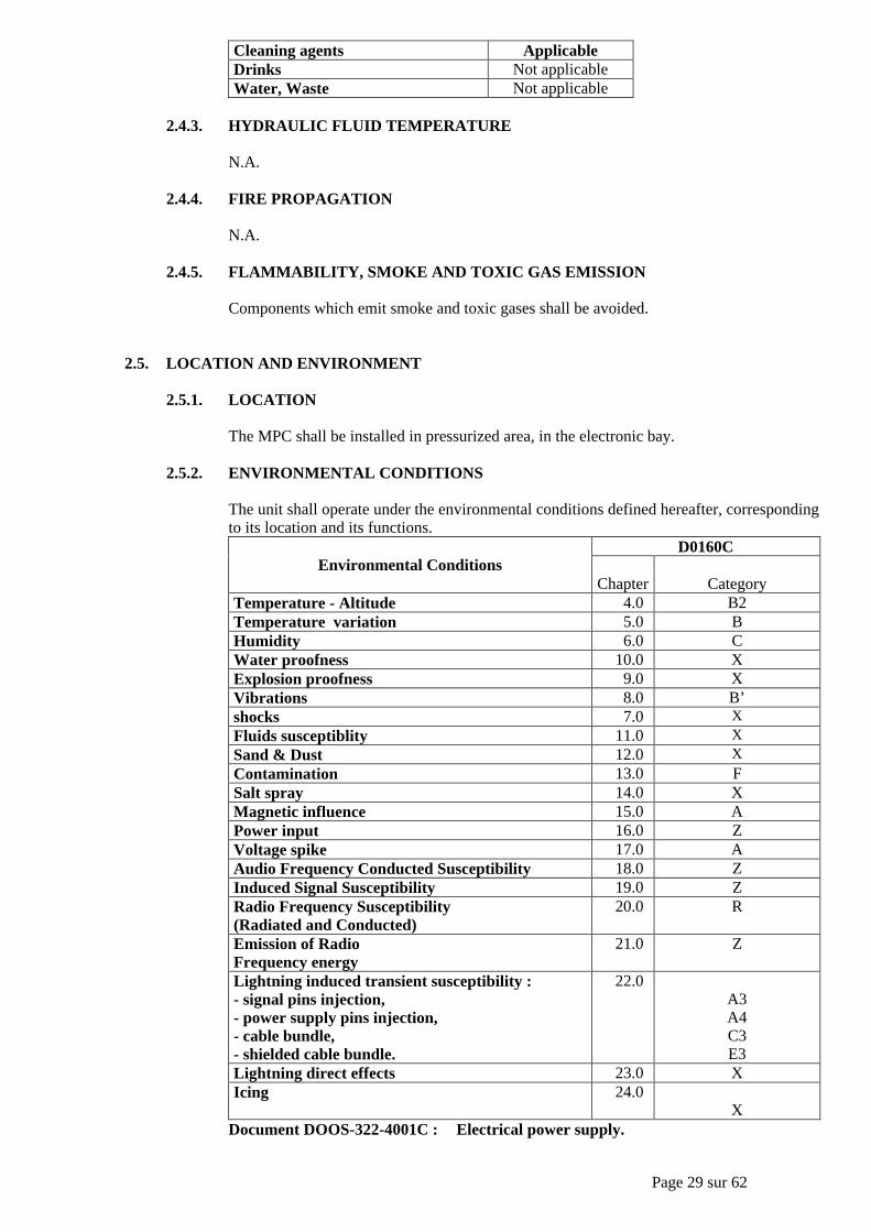
2.5.2. ENVIRONMENTAL CONDITIONS
The unit shall operate under the environmental conditions defined hereafter, correspondingto its location and its functions.
D0160CEnvironmental Conditions
Chapter CategoryTemperature - Altitude 4.0 B2Temperature variation 5.0 BHumidity 6.0 CWater proofness 10.0 XExplosion proofness 9.0 XVibrations 8.0 B’shocks 7.0 XFluids susceptiblity 11.0 XSand & Dust 12.0 XContamination 13.0 FSalt spray 14.0 XMagnetic influence 15.0 APower input 16.0 ZVoltage spike 17.0 AAudio Frequency Conducted Susceptibility 18.0 ZInduced Signal Susceptibility 19.0 ZRadio Frequency Susceptibility(Radiated and Conducted)
20.0 R
Emission of RadioFrequency energy
21.0 Z
Lightning induced transient susceptibility :- signal pins injection,- power supply pins injection,- cable bundle,- shielded cable bundle.
22.0A3A4C3E3
Lightning direct effects 23.0 XIcing 24.0
XDocument DOOS-322-4001C : Electrical power supply.
Page 30 sur 62
2.5.3. HEAT DISSIPATION, VENTILATION, COOLING AND HEATING
2.5.3.1. HEAT DISSIPATIONThe supplier shall take special precautions to solve the problem of the temperatureof the unit. He shall provide the temperature distribution inside the unit, in normaloperating conditions.Heat dissipation shall be minimised.
2.5.3.2. VENTILATION - COOLING
The unit shall comply with Arinc 600 requirements.
2.6. OPERATIONAL DATA
For unit safety and reliability computation, the following data shall be used:• average flight duration :
- fleet 52'- highest 1h50'- lowest 32'
• daily utilization :- fleet 5H 26'- highest 7h59'
2.7. INSTALLATION
The unit shall include a fool-proofing mean in order to prevent erroneous installation on the aircraft.
2.8. NOISE
N.A.
2.9. MASS
The center of gravity shall be indicated by the supplier in this proposal.
2.10. VOLUME
The MPC shall be an Arinc 600 3MCU standard casing.The supplier shall provide an outline drawing.
2.11. PIN PROGRAMMING
The pin programming shall be used to identified all the possible difference in some particularfunctions, and the options.
Page 31 sur 62
3. SAFETY - RELIABILITY - MAINTAINABILITY
3.1. SAFETY - RELIABILITY
3.1.1. DEFINITION OF TERMS
N.A.
3.1.2. SAFETY AND RELIABILITY OBJECTIVES
The supplier shall provide a failure mode and effect analysis.The detailed safety analysis shall give detected and undetected failure rates per function.As the perturbation of aircraft sensors or computers through MPC inputs shall be consideredhaving "Hazardous effects", the supplier shall demonstrate that this type of perturbation isnot possible.
3.1.3. SEGREGATION REQUIREMENTS
3.1.3.1. GENERAL REQUIREMENT
N.A.
3.1.3.2. PROTECTION AGAINST PHYSICAL DISTURBANCE ON INPUTS /OUTPUTS DEDICATED TO ENGINES
Owing to the fact that the unit is a common point to all the engines installed on theaircraft, special care shall be taken in order to comply with the engine isolationcertification requirement (JAR / FAR 25.903 b).Consequently, the interface between the unit and engine dedicated signals shall bedesigned with particular attention to the following points :- Any electrical disturbance shall not propagate through the interface to
inputs/outputs dedicated to engines (electrical disturbance shall be understoodas any external disturbance entering the unit through any external wireinterfacing with it, or as any failure of the unit).
- External disturbance such as short circuit to ground, short circuit betweensignals, inadvertent 28VDC / 5VAC /26VAC / 115VAC voltage, all disturbances onpower supply and on other wires (see environmental conditions) shall beconsidered.
- Failures of the unit to be taken into account shall be determined by the supplierand substantiated to the purchaser.
- There shall be no single failure of the unit affecting the isolation devices onmore than one engine.
3.1.3.3. CHANNELS SEGREGATION - DISSIMILARITY
N.A.
3.1.4. SAFETY TESTS
N.A.
3.1.5. FAILURE ANALYSIS
The supplier shall provide the following documents :
Page 32 sur 62
- a FMEA (Failure Mode and Effects Analysis).The FMEA's shall describe the precise component failure modes and their consequences onthe unit functions. In addition to the functions achieved by the hardware functional blocks(such as power supply, inputs, processor, ...), the main operational functions of the unit haveto be considered.This document shall be reviewed jointly by the purchaser and the supplier according thereview meetings of this specification.A specific analysis document shall be made for the APM & Enhanced surveillance / ADS-Bfunctions.
3.1.5.1. FMEA
The FMEA's shall be in compliance with the following requirement :- it shall give all necessary information to have a clear understanding of the
design of the unit, of its monitoring and safety devices with their fault detectioncoverage, and of its various failure modes.
To reach this goal, the following information will be provided :- a brief but concise description of the unit and its monitoring and failure
detection devices, supported by clear block-diagrams at an "intermediate"complexity level situated between general block-diagrams and electronic cardassembly schematics. The description and the block-diagrams will highlight thebreakdown of the unit into functional blocks,
- an identification of the maid operational functions of the unit,- a reminder of the software architecture,- block-diagrams showing the correlation between the operational functions and
the hardware and software means used to provide these functions,
For each considered elementary failure, the FMEA shall give :- the failure rate per hour, with the origin of the data and the chosen hypothesis
(e.g. : there is an assumption that 10% of the failures of this integrated circuitcan lead to the considered failure mode, for such reasons), plus the physicalconditions (temperature or others) for which the failure rate is given. Thesource from which the reliability data is extracted (e.g. MIL HDBK 217) andthe physical environmental conditions for which the data is given shall beprecised in the FMEA introduction,
- the effect(s) on the unit block to which the component belongs, and the failuredetection means (if the failure cannot be detected, mention it),
- the effect on the operational function(s) of the unit.
The FMEA shall be organized in a legible and structured manner, so as to givestraightforward links with the FMES.
3.1.5.2 FMES
N.A.
3.1.6. HAZARD ANALYSIS
The supplier shall provide a hazard analysis : this document shall identify the hazardsresulting from the unit which their level and the conditions which could lead to it.This document will be reviewed jointly by the purchaser and the supplier according to§12.4. review meetings of this specification.According to the effects on the aircraft identified by the purchaser, a complementaryanalysis will be provided by the supplier.
3.1.7. SPECIAL REQUIREMENTS
N.A.
Page 33 sur 62
3.2. RELIABILITY AND MAINTAINABILITY
3.2.1. DEFINITION OF TERMS
The document applicable for definitions not included in this specification is the worldairlines technical operations glossary (WATOG).•"Failure" and "removal" :
- a unit is considered to have "failed" when it no longer performs the functions for whichit is designed, with the specified performance,
- a failure is said to be confirmed if additional test confirm the failure of the unit. If morethan one failure is discovered within the removed unit it does not constitute anotherfailure,
- a failure is said to be unconfirmed if no component failures are detected and the unitperforms its function nominally,
- an intermediate case exists when the investigation is underway.- "removal" is removal of a unit from the aircraft.
The following actions are not considered to be "removals" :- removing a unit that has been used in conditions other than nominal conditions or that
been damaged during transport or installation,- removing the unit to gain access to another item or equipment or for reasons
unconnected with the function performed by the unit,- removing the unit to embody modifications (retrofit),- crossing of units for trouble shooting purposes,- reracking for any reason.Removal is said to be justified if a failure of the unit is confirmed.
•MTBF (Mean Time Between Failures)The MTBF is obtained by dividing the total number of flight hours logged by all unitsover a certain period of time by the number of confirmed failures which affected all theunits during the same time.
•MTBUR (Mean Time Between Unscheduled Removals)The MTBUR is obtained by dividing the total number of flight hours logged by all unitsover a certain period of time by the number of removals (as defined here above) duringthat same period.
•SERVICE LIFEThe service life of the unit is the time at which it is no longer physically or economicallyfeasible to repair or overhaul the unit to acceptable standards.
3.2.2. RELIABILITY
The supplier shall give and justify the guaranteed MTBF and MTBUR values for acontinuous operation of the unit at the following two ambient temperatures :Calculation of MTBF shall be made according MILHDBK217.The objective for the MTBF guaranteed value is 30000h.
3.2.3. SERVICE LIFE
Service life shall be → TBA.Objective → no limitation (= aircraft service life).
3.3. QUALITY ASSURANCE FOR SAFETY AND MAINTAINABILITY
Compliance with the above mentioned objectives shall be supported by the supplier's answers to thefollowing questionnaire :- safety and maintainability quality check procedure (MQCP questionnaire).

Page 34 sur 62
Reviews related to safety and maintainability are described in §12.4 review meetings.
3.4. DEFECT INVESTIGATION ON REJECTED UNIT
For any rejected unit, and at the request of the purchaser, the supplier shall produce an inspectionreport using a form subject to agreement by the purchaser. This report will be used to inform thepurchaser of investigation on that unit.The supplier shall detail in this report test means used to perform that investigation.
Page 35 sur 62
4. CERTIFICATION AND QUALIFICATION
4.1. DEFINITION OF TERMS
• Type certification :Process to obtain approval by the Airworthiness Authorities that the aircraft with all its unitsinstalled meets the applicable airworthiness requirements.
• Qualification :Process to demonstrate to the Airworthiness Authorities that a unit complies with :- the applicable regulations,- it's specified performance,- within its specified environment.For digital units, software aspects of certification is part of the qualification for certification of theunit. Qualification is part of Type Certification, the other parts being installation of the unit insidethe aircraft, system safety analysis, etc ... .
• Continuing Airworthiness :Process to ensure that the level of airworthiness guaranteed by Type Certification is maintainedfor each individual aircraft at the time of its entry into service (issuance of Certificate ofAirworthiness) and during all its service life. This process involves particularly the control ofaircraft/unit modification beyond the certificated/qualified type design and the corrective actionsneeded to restore, if necessary, the appropriate level of airworthiness.
4.2. REGULATIONS AND CERTIFICATION CONSIDERATIONS
The system is certificated under the responsibility of the purchaser. The applicable airworthinessrequirements are defined in §1.5.3.5. Regulations.
Certification bases (FAR or JAR and additional requirements) can be subject to changes untilcertification.In particular, additional special conditions (which constitute a new regulation) or interpretativematerials (which define acceptable means of compliance to regulations) can be notified through CRIsand issue papers by the airworthiness authorities to cover novel or unusual design features.The rules to be applied are those notified at the time of the certification.
The supplier shall provide the purchaser with the necessary information at the right time in order toshow compliance with these requirements.
4.3. QUALIFICATION
4.3.1. GENERAL
The qualification of the units is under the responsibility of the supplier but has to be agreedby the purchaser and the airworthiness authorities.
• Qualification to environment :
It shall be supported by the demonstration that the unit complies with §2.5. "Locationand Environment" environment requirements.
For this purpose, the supplier shall perform environment tests according to theprocedures defined in DO 160/ED 14, and taking into account the followingrequirements :- Tests shall be carried out with a representative software.
Page 36 sur 62
- The test specimen shall be to production standard. All deviations of the test specimenfrom the production standard shall be listed by the supplier, who shall submit to thepurchaser for approval a written statement evidencing the effects such deviations mayhave on the test results.
- The reasons for defects which occurred during the tests shall be investigated andrecorded by the supplier. They shall be reported to the purchaser when thequalification is delayed.
The following documents shall be provided to the purchaser for the unit :- "Qualification to environment procedures" : it shall include detailed procedures used
for the tests. It shall include the test definition, part of DTS, performed on equipmentbefore and after each environment test.
- "Qualification to environment report" : result of the tests shall be recorded in thisdocument.
• Software aspect of certification :
It shall be supported by the demonstration that the software has been developed incompliance with DO 178 guidelines.DO 178 gives an overview of the software aspects of certification process.
4.3.2. UNIT CATEGORY AND CLASSIFICATION
The unit is classified class C (non-essential).The qualification category is category 2.The software level is C for AFDAU part and D for DMU part.(see definition in DO 178).
4.3.3. QUALIFICATION DOCUMENTS
The following documentation shall be provided by the supplier in English language :• Declaration of Design and Performance (DDP) → it is the master document for the unit
qualification.• Qualification to environment procedures and qualification to environment report.• Software documentation as required by DO 178.• Qualification summary, this document shall summarize :
- the characteristics of the unit relatives to environment, and engine segregationfeature,
- the procedures used to demonstrate compliance to the corresponding requirements,- the results obtained,- the identification of deviations to these requirements, if any.
• In addition, supporting documents or evidence of compliance shall be provided asrequired by the certification authorities.
4.3.4. MINIMUM QUALIFICATION BEFORE DELIVERY OF THE FIRST UNIT
N.A.
4.3.5. QUALIFICATION BEFORE FIRST FLIGHT
N.A.
4.4. CONTINUING AIRWORTHINESS
For any modification (i.e. any unit design evolution including software evolution, new industrialprocesses or new components sources) beyond the qualification standards, and/or for anymodification to operational or maintenance limitations, the supplier has to obtain prior agreementfrom the purchaser.

Page 37 sur 62
The supplier shall provide the purchaser with appropriate information on these modifications ; thework for qualification of the modified unit (and/or modified instructions) shall be proposed by thesupplier and shall be submitted to the purchaser for approval. The supplier shall provide the purchaserwith corresponding justification data.The supplier shall update the unit technical documentation accordingly. The revised qualificationdocuments shall be provided to the purchaser.
In the case of non-compliance with the above, the supplier would bear full liability of theconsequences of the modifications.

Page 38 sur 62
5. SOFTWARE DEVELOPMENT REQUIREMENTS
5.1. SOFTWARE QUALITY CLAUSES
During the development, the supplier shall provide to the purchaser evidence of software qualityclauses.The software level shall be, as defined in §4.3.2, C.
Page 39 sur 62
6. HARDWARE DEVELOPMENT REQUIREMENTS
6.1. DESIGN CAPABILITY EVALUATION OF SUPPLIER
The supplier shall give confidence in the proposal that he will be able to succeed in the technologystep proposed : previous experiences and results, validation or qualification of design andmanufacturing, development in progress, design standards, existing and future tests means.
6.2. DESIGN STANDARDS
The manufacturer shall have, for equipment design, design rules/standards before starting thedevelopment and including as a minimum :- detailed performance hardware definition,- operation and performance simulation / prediction,- verification of signals timing at worst case conditions,- safety analysis part of the design (design repercussions),- maintainability rules at design level,- testability rules at design level,- grounding connection and decoupling design rules for electronic boards,- transients protection / EMC lightning protection,- internal heat management (derating and overheating protection),- circuits board implantation rules,- interconnections rules,- power and signal segregation rules,- design technologies evolutions provisions (margins on max, ex : integration, frequency),- equipment perennially and design impact,- components derating rules for safety margins,- component quality needs definition,- mechanical rigidity,- materials selection versus environment requirements, and protection technologies and safety,- internal design reviews.
6.3. HARDWARE TESTABILITY COVERAGE
The testability shall be developed in parallel to the hardware design in order to obtain a maximumcoverage of the manufacturing tests versus defect risks (functions, performances, hardwareconstituents).The supplier shall calculate and justify the element non-covered.The requirement minimum shall be 98% of coverage.
6.4. SELECTION OF ELECTRONIC COMPONENTS AND ASSEMBLY PROCESSES
6.4.1. TECHNOLOGY QUALIFICATION TESTS
The contractor shall define in his proposal for new/or complex components and assemblytechnologies, the validation or qualification necessary to guarantee the safety reliabilityrequirements (depend of confidence level on result).The validation shall cover :• Components :
- selection rules (standard used, level, list),- components derating rules,- new components qualification tests (standard used, level),- for ASICS qualification shall consider in addition to device qualification :
- design rules,- testability coverage,- functional modes conformity,
Page 40 sur 62
- circuits libraries qualification,- technology qualification procedure (utilization of Technology Characterization
Vehicle (TCV), Standard Evaluation Component (SEC), Parameter Monitoring(PM).
• Technologies and processes :- new assembly technology validation tests,- new processes validation tests.
6.4.2. TECHNOLOGIES MODIFICATIONS AND REQUALIFICATION
After qualification, the technology modifications (or tools having impact on definitions)shall be declared according to §9.2 change management, the validation tests results forperformances and reliability of modifications shall be submitted to the purchaser beforeapplication.After modifications the test specifications will be up-dated and submitted to the purchaser.
6.5. ELECTRONICS COMPONENTS SCREENING TESTS
The contractor shall define and justify the components quality assurance provisions and/or thecomponents screening tests specifications to detect the components potentially failing. This in orderto guarantee the safety reliability requirements of the unit.
The minimum recommended is dynamic burs-in tests for Asics, microprocessors, memories, hybrids,power analog circuits.
6.6. SELECTION OF MATERIALS
N.A.
6.7. HARDWARE QUALITY CLAUSES
The supplier shall establish and maintain a quality assurance plan in compliance with the qualityrequirements of the purchaser.The equipment quality clauses applicable to the unit are defined in the document D-06.01.The supplier shall provide the documents listed in the tables hereafter, corresponding to the categoryof the unit, and in addition to these documents he shall provide the "design development plan"including :- configuration management plan,- qualification plan for certification,- component standardization method.
6.8. ASICS QUALITY CLAUSES
The quality clauses and the documentation applicable for ASICS are defined in quality documentschapter1.5.2.2, and in AFDAU specification 542.0014/01 tables added in chapter 6.8 (complexcomponent).
Page 41 sur 62
7. MANUFACTURING AND TESTS
7.1. MANUFACTURING AND SCREENING
7.1.1. MANUFACTURING
The manufacturing and inspection flow-chart "Industrial production process flow-chart" shallbe compliant with D-74.01 document.This flow chart shall be presented in tree structure form:- Main equipment production phases from the subassemblies manufactured by the supplier or
procured to equipment shipment,- Main subassemnbly production phases.The supplier shall specify in this flow chart the manufacturing , inspection and test operations.The supplier shall manage the configuration of this flow chart,the associated baselines and the
link between the flow chart and the manufacturing and inspection files.
7.1.2. SCREENING SPECIFICATION
• Purpose of screeningThe purpose of the screening shall be to guarantee that the early life failure rate of theequipment and spare parts will not exceed 1/MTBF theoretical value (failure rate constantdue to exponential failure distribution in electronic) and that the infant mortality failureswill be sufficiently reduced.Screening operation are environmental stresses (within the limits of this specification)applied on each item of equipment or sub-assembly in function with duration andconstraints sufficient to eliminate the infant mortality.The supplier guarantees that before and after the screening the equipment operate correctly.
• Screening specification / justificationThe supplier shall define and justify the screening conditions to apply at each unit as part ofmanufacturing tests.The conditions shall be determined by an efficiency analysis of conditions (temperature,time , cycles, power, signals, mechanical, ...) submitted to review by the purchaser.
7.2. MANUFACTURING TEST
7.2.1. MANUFACTURING DETAILED TEST SPECIFICATION (DTS)
• Purpose of the DTSThe purpose of the DTS is to define the requirements for all production tests andinspections to perform on each unit (LRU) and on sub-assembly (SRU), for approval beforedelivery of item of equipment.The tests strategy and specification for the complete item and the sub-assemblies (SRU,components, ...) necessary along production of item to deliver an item of equipment meetingthe requirements are in DTS.
7.2.2. ACCEPTANCE TEST SPECIFICATION (ATS)
The ATS is part of DTS and specify the requirements for the acceptance tests of complete unit(see below).
7.2.2.1. ATS DEFINITION
The purpose of the acceptance test is to guarantee that the item of equipment meetsthe contractual technical specification and its definition dossier.The acceptance tests address the tests of the hardware part of the item of equipmentand the identification of embedded software configuration.
Page 42 sur 62
The aircraft system functions associated with the software are considered to bequalified by software design qualification (as per DO178) and the functional testsperformed for design validation.The acceptance test specification (ATS) defines the requirements for all tests andinspections to be performed on each complete item of equipment (LRU) to authorizedthe release to the purchaser.The ATS includes the location of defects detected by test at SRU (Shop ReplaceableUnit) level.Sub assembly of unit (item of equipment) replaceable without tool ... (e.g. boards,connectors, functional modules, ...).
7.2.2.2. ACCEPTANCE TEST AND TEST COVERAGE ANALYSIS APPROVAL
The ATS and test coverage analysis results shall be submitted to the purchaser forapproval.Revision → The methodology of ATS revision shall be submitted to the purchaser for
approval.→ Each ATS revision shall be submitted to the purchaser for approval.
7.2.2.3. TEST COVERAGE REQUIREMENTS
The objective of the ATS is to test 100% of the hardware of an item of equipment.
If the hardware of the item of equipment cannot be tested 100%, the ATS shall giveacceptable confidence that the item of equipment meets its requirements. In this casethe supplier shall demonstrate the following elements :- coverage of 100% of the hardware functions of the complete item (e.g. : power
supply, Arinc data inputs, analogic data input),- minimum weighted test coverage 92%,- minimum identification of defect at SRU level 80%
In addition the supplier shall provide the identification of components and hardwarefunctions not covered by the tests.The LRU acceptance test duration shall be minimised.The supplier shall propose a test duration which shall be submitted to the purchaserfor approval.The supplier shall indicated the intrinsic minimum test duration part due to the itemof equipment itself and the part due to the test tool.For each testability objective not reached, justifications shall be given to thepurchaser.
• Test coverage analysis demonstration
The test coverage analysis method shall be delivered to the purchaser for review.The coverage analysis results shall be submitted to the purchaser for approval.These elements shall be part of the acceptance criteria for design reviews(Preliminary Design Review and Critical Design Review) : see Design Reviewdefinitions.
- Definition of test coverage ratio (C) → the testing coverage is the ratio (C) of := number of components testeddivided by := total number of existing components.Note → for each multifunction component such as Asic :
- at the numerator the figure to be used will be (% of functions usedwhich are covered by the test),
- at the denominator the figure is 1.- Definition of weighted testing coverage :
To obtain a weighted testing coverage, in the above ratio :- numerator = sum (LAMDAi * Ci) :
Page 43 sur 62
. lamdai = failure rate of component i,
. Ci = % of component functions tested,
. Ci value is between 0 and 1,
. i = 1 to with n = components tested.- denominator :
. sum (LAMDAi),
. i = 1 to t with t = total number of components.
• Acceptable means of compliance
Hardware detailed functional breakdown definition.Identification of detailed hardware functions tested and not-tested.Identification of components tested and not-tested.Note → A component is considered to be tested if all the hardware functions
in which it participates are tested.Calculation of test coverage ratio (C).When necessary, calculation of weighted test coverage.
7.2.2.4. MINIMUM ATS CONTENT
The ATS shall comprise at least the following items :- visual inspection,- physical characteristics,- hardware functions of the complete item of equipment (LRU),- means of identification of embedded software configuration,- the presence of lightning protection devices,- hardware performance.:
. the specified performances of the item of equipment,
. the worst case switching conditions,
. the worst case input / output stimuli conditions,
. the worst case power supply characteristics (e.g. min or max),
. Arinc interfaces,
. input / output insulation,
. grounding.- identification of hardware not covered by the test,- identification of defect at SRU level.
For each test selected the ATS shall describe :- the acceptance criteria,- the test conditions (input stimuli, output),- the test sequences,- the hardware tested,- the parameters tested or checked,- the digital interaction protocols,- the output tolerances,- key parameters to be followed by SPC if applicable (Statistical Process Control),- the outline drawing of specific interfaces, if any,- identification of necessary special test equipment.
• Form of the ATS :The ATS shall be a self-explanatory document and written in clear language inEnglish (ATLAS is not considered as a clear language).The ATS shall be built up per function tested, stimulus applied and type ofmeasurement (analog, discrete, digital signals) in order to facilitate failureinvestigation.The unit part number and the ATR ATR code number shall be indicated in thisdocument.The planning of the various ATS documentation delivery (acceptance testsspecification, tests coverage analysis demonstration, maintenance testspecification, are specified in the contract.
Page 44 sur 62
Note → the supplier shall maintain at the purchaser's disposal the completedocumentation related to the manufacture of his own acceptance testbenches : devices used, specific circuit board drawing, completedocumentation of the specific programs or micro-programs (with code)developed by the supplier for testing.
This documentation shall be sent, on request, to the purchaser.
7.2.3. ATLAS TEST SPECIFICATION
N.A.
7.2.4. MAINTENANCE TEST SPECIFICATION (MTS)
• Purpose :The purpose of the MTS is to define the requirements for all the tests and inspections to beperformed for the maintenance of the item of equipment (LRU).
• MTS requirement :The maintenance test specification shall be identical to the acceptance test specification.
7.2.5. ACCEPTANCE TEST DOCUMENTATION DELIVERY
The planning of the various test documentation delivery are specified in the contract(acceptance test specification and its test coverage analysis demonstration, maintenance testspecification).
Specific appendix to the contract can precise, if necessary, the particular documentation neededfor automatic test equipment program realization.
Page 45 sur 62
8. QUALITY ASSURANCE
8.1. GENERAL
The supplier shall establish and maintain a quality assurance system in compliance with the qualityrequirements of the purchaser mentioned in the directive D-74.01. This quality assurance system shallallow the purchaser to evaluate through an Industrial Process Control Evaluation (see the documentM.011) the quality of the unit development process and to verify, by appropriate test means, that thequality of serial production units is maintained.
This system must be described in a quality assurance plan, a copy of which shall be provided in thesupplier's proposal.
8.2. QUALITY ASSURANCE PROVISIONS THROUGHOUT THE LIFE CYCLE
For each item of equipment, quality assurance is based on establishment by the supplier of qualifyassurance provisions throughout the life cycle of the equipment.
These quality assurance provisions shall allow the purchaser to evaluate the quality of the unitdevelopment (design and industrialization) and to verify that the quality of the serial production unitswill be assured.
Page 46 sur 62
9. CONFIGURATION MANAGEMENT
9.1. IDENTIFICATION
The identification and nameplates of the units shall be permanent and legible.In addition, the country origin of the units shall be indicated on the identification plate with the mention →"Made In ..".
The position of the identification marking shall be submitted to the purchaser for approval, and shall beshown on the outline drawing.
Designation of the unit is "MPC".
The units shall have only 2 plates attached (identification and amendment). The ATR code shall be stated inaccordance with the contract.
This identification shall include hardware and resident software standard identification.The external marking of the product shall be performed in accordance with the directive D-75.03.
9.2. CHANGE MANAGEMENT
The supplier shall comply with the standard methods used by the purchaser for modificationprocedure :- as described hereafter for practical detailed aspects.
9.2.1. MODIFICATION WITH SPECIFICATION EVOLUTION (DCR, DCI/EMS)
The specification evolution is initiated by the "DCR" (Design Change Request) issued bythe purchaser, which indicates :- the reason for the modification,- the new requirement.
• A DCR is a technical request, to allow contractual evaluation (possible cost and lead-time repercussions).
• In this technical reply, the supplier shall indicate the nature of the solution provided andthe incidence on :- weight, volume, reliability, power consumption,- all provisions,- purchaser and supplier's development spares.
• After contractual agreement, a DCR becomes a full part of the specification.• When the purchaser has decided to embody the DCR's, these DCR's are grouped together
into a DCI (Design Change Instruction) or an equivalent document which defines a newunit standard and which is issued by the purchaser.
• DCRs can be issued by the purchaser on the recommendation of the supplier who hassuggested desirable evolutions and/or corrections to the specification.
9.2.2. MODIFICATIONS OF THE UNIT TO SATISFY THE TECHNICALSPECIFICATION
When a unit has to be modified to comply with the technical specification because ofanomalies, there shall be neither contractual repercussions, nor corresponding DCRs.
Anomalies discovered at the purchaser's premises are notified to the supplier through EPR(Equipment Problem Report). All solutions shall be described to the purchaser.
Page 47 sur 62
If these solutions have an impact on specified objectives (MTBF, weight, powerconsumption, installation, qualification tests, ...), the purchaser's agreement has to beobtained before the correction is made.
These corrections can be proposed either by the supplier himself, or by the purchaser. Aparticular procedure shall be jointly agreed for this problem/correction follow-up.The correction shall be described by the supplier on a SDR (System Defect Report) andsubmitted to the purchaser for approval.
The EMS shall reflect these modification.
The same rules shall apply for a modification proposed by the supplier in an area for whichhe is responsible.
9.2.3. OTHER MODIFICATIONS
Any suggested definition change, shall be stated by the supplier and submitted to thepurchaser for agreement in written form. The information shall be sufficient to enable thepurchaser to make a decision.
The decision as to the classification as a unit modification, or as a unit amendment, will bemade by the purchaser after a proposal by the supplier.
When a modification is agreed by the purchaser, an EMS is issued.
9.2.4. SOFTWARE CHANGE IMPLEMENTATION
For software change implementation, the supplier shall use a procedure to allow themodified unit to be made available quickly in Toulouse, with the correspondingdocumentation respecting the specified software quality clauses.As an objective, the supplier should have a tool in Toulouse for updating software (using adata link for software transmission and an emulator to implement the change) and validatingthe implementation of the change (supplier's test bench).
In his reply the supplier shall propose a software change implementation method.
9.2.5. CHANGE DOCUMENTATION
For each new unit standard (Hardware or software change) initiated during development andafter aircraft certification, the supplier shall provide the purchaser with a documentdescribing the changes : system change report.
This document shall describe all the changes (including supplier's changes). The changesshall be identified by comparison with the L0, L1, L2, and L3 standards as defined in §14.1delivery standards for development phases.
The description of changes shall include the reason for the changes, the process affected,identification of the corresponding DCR, EPR and supplier's changes, and, if any, the effectof the changes on the functions interfacing with the aircraft.The document shall also describe the limitations (EPR not corrected, anomalies identifiedby the supplier and not corrected).
In addition, for each standard identified in §14.1 delivery standards for development phases,and each certification standard, the document shall precise :- RAM, ROM and EEPROM memories capacities (available, used, margins),- timing margins.

Page 48 sur 62
The document shall be provided for each new standard no later than the unit delivery duringdevelopment, and before change initiation after certificate. It shall be appended to thesoftware configuration index document (refer to DO 178 for description of this document).

Page 49 sur 62
10. METHOD AND TOOLS
N.A.
Page 50 sur 62
11. TECHNICAL RESPONSIBILITIES ORGANIZATION
11.1. PURCHASER AND SUPPLIER TECHNICAL RESPONSIBILITIES
General responsibilities are defined in the contracts, the general conditions of purchase. In addition,the following applies.
11.1.1. GENERAL
The supplier shall ask the purchaser for any additional information required for making theunit comply with this technical specification if it is not provided in this technicalspecification.
As an "expert", the supplier shall draw the purchaser's attention to any deficiencies oromissions that he feels exist within the specified requirements.
If requested by the purchaser, the supplier shall provide the purchaser with the elements ofthe manufacturing drawings (including blanks), production processes, component ormaterial specifications required for solving any technical problem that might occur.
For any significant unit modification in relationship with the definition indicated in thesupplier technical proposal, the supplier shall inform the purchaser and obtain his agreementin a timely manner to keep the program schedule.
On the supplier's side, all technical matters shall be coordinated by an appointed programmanagement engineer.
11.1.2. PROVISIONS AND DEVELOPMENT SPARES RESPONSIBILITIES
When provisions and development spares are concerned, the following applies :- the definition of the basic unit capacity (see §2.3.4 unit capacity) is the supplier's
responsibility,- the definition of the purchaser development spares (see §2.3.4. unit capacity) is the
purchaser's responsibility,- any change in the purchaser's development spares shall be brought to the purchaser's
knowledge and be submitted to him for approval.
11.1.3. SOFTWARE RESPONSIBILITY
11.1.3.1. SUPPLIER RESPONSIBILITIES
The supplier is responsible for the following activities :- the supplier is responsible for the software level as regards the airworthiness
authorities,- from the purchaser's equipment technical specification and associated
documents (as defined in §1.1 purpose) the supplier is in charge of softwareplanning, software development, verification, configuration management,quality assurance, documentation and all related activities, in accordance withDO 178 and software quality clauses,
- the supplier shall set up all necessary tools to achieve the softwaredevelopment,
- the supplier shall qualify any tool requiring it as defined in DO 178.
11.1.3.2. PURCHASER RESPONSIBILITIES
The purchaser is responsible for the following tasks :
Page 51 sur 62
- the purchaser defines the critically class of the unit,- the purchaser defines the software critically level in agreement with the
airworthiness authorities.
11.2. DEVELOPMENT PHASES
The following development phases shall be considered for the program :• The design phase up to delivery of the first unit by supplier. This phase includes elementary
phases at the supplier's, according to the development cycle defined by him (for example :planning, requirement development, design, tests ...).
• The "mise au point" phase which includes :- preliminary supplier's laboratory tests → their purpose is to validate hardware characteristics
and system architecture,- ground tests, they consist in validation of the units on aircraft on ground tests,- flight tests.
The "mise au point" phase ends with the qualification of the unit which fully meets this technicalspecification and DCRs (see § 9.2. change management) existing at the type certification date.
11.3. ORGANIZATION - INTEGRATED TEAMS
N.A.
Page 52 sur 62
12. PROJECT MANAGEMENT
12.1. PROGRESS MEETINGS
Progress meetings shall be planned, in accordance between purchaser and supplier, during all thedevelopment phases between the purchaser and the supplier's teams.The purpose of these meetings is to make a status report of all the processes of development(specification, evolution, deliveries, ...), to plan necessary technical meetings and to plan DCRsimplementation. Detailed technical discussions shall be avoided during progress meetings. these shalltake place in specific technical meetings.The list of participants shall be established by the purchaser. Results of these meetings shall berecorder in reports including list of actions, due dates and corresponding holders. The reports shall beestablished by the purchaser and co-signed by the supplier.
12.2. TECHNICAL MEETINGS
Specific technical meetings shall take place, on the purchaser request, in order to discuss in detailsspecific technical points between the purchaser and the supplier.Results of these meetings shall be recorded in reports.
12.3. MANAGEMENT MEETINGS
These meetings shall be planned periodically in accordance between purchaser and supplier, duringthe development phases between the purchaser and the supplier program managers. They shall dealwith all the equipment supplied. The purpose of these meetings is to make a status report of maindevelopment points and to decide on actions to be taken in order to solve major problems.Meeting reports shall be established by the purchaser.
12.4. REVIEW MEETINGS
The purpose of the review meetings shall be to materialize the passing of the development steps, andto state if all the works and documents foreseen for these reviews have been performed and areacceptable.
At the beginning of the program : the purpose is mainly to have a presentation of the unit supplier'steams, methods, means and plans, check their adequacy towards the objectives to be achieved andpoint out the potential difficulties.
Formal review meetings shall be organized by the supplier and conducted by the purchaser. Theyshall be planned according to the purchaser's agenda.
Prior to each review, documents produced by the supplier during the elementary phase shall bedelivered to the purchaser 2 weeks before the review meeting in order to prepare the review, thedetailed agenda of the review shall be mutually agreed.
Result of the reviews shall be recorded in reports. Conclusions and actions with due dates shall be co-signed by the supplier and the purchaser.
Each review group shall include participants or specialists not involved directly in unit'sresponsibility and may be constituted of sub-review groups by speciality. This review(s) group(s)shall express recommendations to the unit's responsible.
Page 53 sur 62
For each review a synthesis meeting (review board) shall be held between the responsible after thereview group(s) meeting(s), and shall state if all the works and documents foreseen for these reviewhave been performed and are acceptable.The responsibility of the purchaser is engaged only with the documents he approves.
The minimum reviews to be held shall be as the following. Should the objectives hereafter definednot be met, additional reviews would be planned during the development.
The data to be examined in review shall be based on the detailed checklist here after §12.4.2. to12.4.6. The exact elements to review shall be defined by the review agenda and based on thecontractual "unit data/document".
12.4.1. REVIEWS LIST
N.A.
12.4.2. PLANS REVIEW (PR)
PR synthesis meeting (PR board) → the PR synthesis meeting at equipment level shall beperformed after examination in review group(s) of the following minimum elements :• PR equipment elements
- Design Development and qualification Planning Review (DDPR) with technicaloptions selected and keys dates of those to be selected,
- Asics Quality Assurance Plan Review (AQAPR),participants : supplier responsible and teams - ATR ATR.
• PR software elements- Planning Process Review (PPR). According to the need for the tools qualification (see
DO 178), the following review shall be planned (eventually for each tool) :- Tool Development Planning Review (TDPR),
participants : supplier responsible and teams - ATR ATR.• PR safety and maintainability elements
Included in DDPR.• PR quality assurance elements
- examination of Quality Assurance Plan (QAPR),- examination of organization specific to the product life cycle,- presentation of the manufacturing process control elements to be define and reviewed
before CDR.Participants : supplier responsible and teams - ATR ATR.
12.4.3. PRELIMINARY DESIGN REVIEW (PDR)
• Purpose of PDRValidate that the equipment definition and the supplier equipment specifications, willsatisfy the technical requirement specification from the aircraft manufacturer.The main lines of the equipment design, the test programs of the equipment supplier andthe selected technological options shall be identified. The new technologies to bevalidated shall be identified and presented with a risk analysis.
PDR synthesis meeting (PDR board)The PDR synthesis meeting at equipment level shall be performed after examination inreview group(s) of the following minimum elements :• PDR elements
for each PDR element :- examination of actions defined in previous review (PR),- examination of evolutions from previous reviews (PR).
• PDR equipment design elements (Equipment Preliminary Design Review EPDR) :- equipment specification (supplier),- hardware architecture and hardware performances of the unit,
Page 54 sur 62
- hardware/software sharing and hardware/software interfaces,- input/output design,- EMI and lightning protection,- compliance with segregation requirements,- transient protections,- hardware involved in fault detection and monitoring,- heat dissipation,- equipment design standards and tools (see §2.4),- equipment test strategy justification,- equipment testability coverage definition,- equipment preliminary detailed test specification,- component quality needs definitions : temperature range, quality assurance,
screening, ....- needs for new component qualifications,- Asics preliminary technical requirement specification,- Asics qualification procedure,- needs for new material qualifications,- needs for new technology validations,- needs for new assembly process validations,- needs for manufacturing and inspection documents,- needs for mean and tool validations,- analysis of qualification for certification planning and identification of critical path.Participants : supplier responsible and teams - ATR ATR.
• PDR software elements- Software Requirement Review (SRR)Participants : supplier responsible and teams - ATR ATR.
• PDR safety elements (Safety Preliminary Design Review SPDR)- preliminary architecture analysis with respect to objectives and applicable rules,- planned design precautions,- monitoring design (hardware and software wise) and tests definition,- safety tests definition,- FMEA plan and method for compiling the FMES.Participants : supplier responsible and teams - ATR ATR.
• PDR maintainability elements (Maintainability Preliminary Design Review MPDR)- bite definition and rules application,- failure warning classification.Participants : supplier responsible and teams - ATR ATR.
• PDR quality assurance elements- examination of evolutions of quality assurance plan.Participants : supplier responsible and teams - ATR ATR.
12.4.4. CRITICAL DESIGN REVIEW (CDR)
• Purpose of CDRValidate the detailed design of the equipment and the industrial realization and supplythe necessary justification.
CDR synthesis meeting (CDR board)The CDR synthesis meeting at equipment level shall be performed after examination inreview group(s) of the following minimum elements :• CDR elements
For each CDR element :- examination of actions defined in previous review (PDR),- examination of evolutions from previous review (PDR),- consolidated elements of PDR.
• CDR equipment elements (Equipment Critical Design Review ECDR)- equipment design description documents (part of Definition Dossier DD),- results of verification/simulation of operation and performances at worst case
conditions,
Page 55 sur 62
- first equipment prototype presentation,- manufacturing process and inspections detailed flow-chart,- equipment screening requirements,- Detailed Test Specification (DTS) all along the process,- equipment tests coverage justifications including test strategy,- analysis and validation of stress on components in equipment,- component screening list,- new component qualification summary results,- Asics technical specification,- Asics FMEA,- Asics testability,- Asics qualification results,- new technology qualification summary results,- new material qualification summary results,- new assembly process validation summary results,- program and procedure of equipment qualification to environment,- analysis of qualification for certification planning and identification of critical path,- preliminary results on equipment qualification to environment related to risks
analysis.Note →above justifications may be summarized in a "Definition Justification Dossier"
(DJD).Participants : supplier responsible and teams - ATR ATR.
• CDR software elements- Software Critical Design Review (SW-CDR)Participants : supplier responsible and teams - ATR ATR.
• CDR safety elements Safety Critical Design Review (SCDR)- architecture analysis,- preliminary FMEA/FMES to check the main failure modes assessment,- hazard analysis,- list of failures detected by safety tests (including power on tests),- demonstration of safety tests execution.Participants : supplier responsible and teams - ATR ATR.
• CDR maintainability elements (Maintainability Critical Design Review MCDR)- bite design (hard and soft) for interfaces, maintenance messages, indications for
different classes, cockpit effect,- description of monitoring and fault coverage.Participants : supplier responsible and teams - ATR ATR.
• CDR quality assurance elements- examination of evolutions of quality assurance plan,- evaluation of manufacturing process control including :
- processes risks analysis and key characteristics definition and monitoring,- tests and inspections all along the process,- new technologies,- examination of knowledge, training and respect of QAP,- examination of manufacturing and inspection dossier that will be finalized at
FFAR.Participants : supplier responsible and teams - ATR.
12.4.5. LABORATORY UNIT ACCEPTANCE (LUA)
Purpose of LUA :
Validate that the equipment produced for ATR integration laboratory tests (standard L1,laboratory and ground tests standard see §14.1 delivery standards for development phases),satisfy the specified functions and that the Delivered software has been developed accordingto the methodology agreed at the plan review.Pronounce on the acceptation of the requirement at L1 standard.This meeting shall be planned just before delivery to the purchaser of the L1 standard.
• LUA equipment elements
Page 56 sur 62
- manufacturing acceptance tests results (results of L1 ATP),- functional test results, these tests shall be run on the supplier's benches. For this
purpose a functional tests document shall be written by the supplier and submitted tothe purchaser's approval prior to the meeting.This document shall include :- description of the supplier bench used to run the tests,- detailed description of the test procedures with test conditions (e.g. unit
configuration and inputs applied) and results expected and obtained.The supplier shall run tests before the meeting and inform the purchaser about theresults.
Participants : supplier responsible and teams - ATR.• LUA software elements
- First Delivery Review (FDR), according to the need for the tools qualification (seeDO 178), the following review shall be planned (eventually for each tool),
- Tool Acceptance Review (TAR).Participants : supplier responsible and teams - ATR.
12.4.6. FIRST FLIGHT ARTICLE REVIEW (FFAR)
• Purpose of FFARValidate that the equipment intended for first flight has been produced on industrialprocesses and means defined and validated at CDR, and satisfy the industrial dossier(definition, manufacturing, inspections, tests).Pronounce on the acceptation of equipment first flight standard (L2 see §14.1 deliverystandards for development phases).
FFAR synthesis meeting (FFAR board)The FFAR synthesis meeting at equipment level shall be performed after examination inreview group(s) of following minimum elements :• FFAR elements
For each FFAR element :- examination of actions defined in previous review (CDR),- examination of evolutions from previous review (CDR),- take into account ATR laboratory test results and aircraft ground tests results.
• FFAR equipment elements (Equipment First Flight Article Review EFFAR)- manufacturing acceptance test results (ATP), for first flight standard (L2),- functional test results for L2 (see LUA),- equipment manufacturing and inspection dossiers,- equipment screening results,- manufacturing detailed test results,- equipment manufacturing test coverage demonstration,- analysis of qualification for certification planning and identification of critical patch,- main results of equipment qualification to environment.
→ criteria's :- consequence on design,- risk of immediate dysfunctionning on flight,- consequence on manufacturing process and tests strategy.
Participants : supplier responsible and teams - ATR.• FFAR software elements
- Software First Flight Review (FFR)Participants : supplier responsible and teams - ATR.
• FFAR safety elements (Final Safety Review FSR)- Final review of FMEA/FMES on serial units.Participants : supplier responsible and teams - ATR.
• FFAR maintainability element (Final Maintainability Review FMR)- bite description document,- laboratory test report on L2 (messages management and results).Participants : supplier responsible and teams - ATR.
• FFAR quality assurance elements
Page 57 sur 62
- examination of evolutions of quality assurance plan.Participants : supplier responsible and teams - ATR.
12.4.7. CERTIFICATION FIRST ARTICLE REVIEW (CFAR)
• Purpose of CFCARValidate that the elements necessary to pass successfully the certification are met.
CFAR synthesis meeting (CFAR board)The CFAR synthesis meeting at equipment level shall be performed after examination inreview group(s) of the following minimum elements:• CFAR elements
For each CFAR element :- examination of actions defined in previous review (FFAR),- examination of evolutions from previous review (FFAR),- consolidation of elements of FFAR,- take into account laboratory test results and aircraft flight-tests results.
• Equipment (Equipment Certification First Article Review ECFAR)- final results of equipment qualification to environment,- manufacturing acceptance test results (ATP), for certification standard (L3-see §14.1
delivery standards for development phases),- functional test results for L3 (see LUA),- DDP.Participants : supplier responsible and teams - ATR.
• Software elements- Compliance Review Certification (CRC).According to the need for the tool qualification (see DO 178), the following reviewsshall be planned (eventually for each tool) :- Compliance Review for in House Tool Qualification (CRHQ),- Compliance Review for Commercial Tool Qualification (CRCQ).Participants : supplier responsible and teams - ATR.
• CFAR quality assurance elements- examination of evolutions of quality assurance plan.Participants : supplier responsible and teams - ATR.
12.5. PERFORMANCES ASSESSMENT
N.A.
12.6. AUDITS
During the “development” phase, an audit shall be performed by the purchaser in accordance with thedocument M011, before the delivery of the first items to the final assembly line. During the“production” phase, audits are not planned, but shall be initiated by the purchaser according to theevents.The purpose of audits is to determine whether the supplier's activity, methodology and results complywith the supplier's previous definition and allow the objectives to be achieved.Audits shall be conducted by the purchaser's auditors with the participation of the supplier's projectteams.
An audit could consist of :- reply to a questionnaire,- interviews,- demonstrations,- others.Minutes of the audits will be written by the purchaser.
In addition, see the software quality clauses of software audits

Page 58 sur 62
13. STORAGE AND HANDLING
N.A.
Page 59 sur 62
14. SUPPLYING
14.1. DELIVERY STANDARD FOR DEVELOPMENT PHASES
The following delivery standards are identified for the development phase :- L1 first prototype for flight tests, software level “C” ATR 72 configuration and basic level “D”functions (G-Meter, QAR, DAR and MCDU visualisation)- L2 second prototype for flight tests, software level “C” for ATR 72 configuration & level “D” forall configurations without FDEP function- L3 . third prototype for flight tests software level “C & D” for all aircraft configurations, withFDEP function.- L4 for certification
• L1 → 1st prototype "Red Label" for laboratory, ground and flight tests with sotware level “C” inATR 72 configuration and basic level “D” functions (G-Meter, QAR, DAR and MCDUvisualisation)
This L1 standard shall be used for flight test in airline, for this, the standard shall be covered by an“intermediate certification” regarding DO178 requirements. Minimum tests shall be done, and a statement regarding these tests shall be provided by thesupplier to the purchaser associated to an intermediate DDP, to demonstrate the navigability of theequipment regarding DO160 & DO178.
• L2 → 2nd prototype "Red Label" for ground and flight tests The software implemented shall consist of :- L1 + corrected anomalies (if any),- DCRs implementation (if any),- Adjustement following ground and flight test results (if necessary),- Software level “D” for all aircraft configurations without integrated FDEP function
• L3 → 3rd prototype “Red label” for ground and flight testsThe software implemented shall consist of:- L2 + corrected anomalies (if any),- DCR’s implementation (if any),- Adjustement following ground and flight test results (if necessary), - Software level “C”
for all aircraft configurations.- Software level “D” complete (with integrated FDEP function).
• L4 → certification standardThis standard shall be delivered to purchaser in order to perform certification flights and todelivered to the first customer.the software implemented shall be complete and without anomalies. This standard shall include allagreed DCRs. (The list of DCR shall be submitted to the purchaser of approval).
14.2. TECHNICAL DATA / DOCUMENTATION
14.2.1. GENERAL
All documents and drawing shall be clearly identified with unambiguous reference numbers,issue, date ... . Modifications towards the previous issue of the document shall be clearlyindicated. All documents shall be continuously kept up to date, according to specificationchanges and/or equipment definition evolutions, and sent to the purchaser.
The documents shall be written in English language when required.The supplier shall use international system units (kg, ampere, volt, Newton, seconds, watt,meter, Celcius). His own system units shall be mentioned, if necessary, between brackets.
Page 60 sur 62
14.2.2. SUPPLIER'S TECHNICAL PROPOSAL
14.2.2.1. CONTENTSThe supplier shall quote in his proposal :- the different configurations described in §2.2.2 System Architecture,- the alternative solutions (if any proposed by supplier),- ...The supplier's technical proposal shall included the following data :- An outline drawing which shall comprise :
- all the views required for showing the overall dimensions,- all the interface dimensions or standards,- the labels and marking on the unit,- the space required to remove all the LRU's,- the wiring diagram.
The purchaser may update the space envelope and interface drawing which is partof the contractual specification accordingly. He may use any interface informationincluded in the outline drawing.This outline drawing shall be kept fully representative of the interface between theunit and the aircraft during the development phase, but no modification can bemade to it unless agreed by the purchaser.After the purchaser's approval, the updated outline drawing will be included in theacceptance test procedure.- A full-scale section drawing including all the views required for understanding
the construction and operation of the unit.- A description of the unit including the schematic diagram required for
understanding its operation and the features of the main components, adescription of the technology to be used ; the justification of the maturity of themanufacturing techniques.
- A performance assessment showing that the proposed design fulfils theperformance requirements.
- The basic unit capacity, purchaser development spares and growth capability asrequired by §2.3 Unit Capacity and § Growth Capability and the RelevantSubstantiation.
- The schemes describing the solution to the segregation requirement (see§3.1.3.2 Protection against physical disturbance on inputs/outputs dedicated toengines).
- The unit failure to be taken into account when this segregation is concerned,and the relevant substantiation.
- The description of the possible alternative designs, that might be proposed andtheir quantified advantage in terms of weight, cost ... .
- A detailed weight breakdown.- A part list giving the materials and treatments.- A preliminary failure analysis (FMEA as described in §3.1.5.2 FMEA).- The reliability prediction data.- The maintainability data sheet.- A qualification to environment plan giving the list of the tests proposed, the
number of units and test rigs required, the test laboratories involved.- The quality assurance manual.- A development plan.- The answers to the software quality clauses as listed in §5.1 software quality
clauses.- The description of the tools he intends to use for the software development, test
and configuration management.- The data mentioned as To Be Answered (TBA) in this technical specification
and the relevant substantiation :- power consumption,
Page 61 sur 62
- documents used for environment tests defined in addition to DO 160,- heat dissipation,- noise,- MTBF and MTBUR,- service life,- fatigue life,- qualification program.
14.2.2.2. REQUIRED PROPOSAL PLAN AND FORM
The supplier is required to use exactly the same plan in his proposal as thistechnical specification plan. If this is not possible, the supplier shall draw up atable of cross-references between the § of his proposal and this technicalspecification.
The technical proposal shall be written in English language. Exceptionally,answers in French may be authorized on request from the supplier. If this requestis accepted, the supplier must promise to send the purchaser en English translationof his proposal within 15 days should the purchaser so request.
14.2.3. EQUIPMENT DOCUMENTS
The supplier shall provide the documents listed here after, and agreed between purchaserand supplier.
SRD System SpecificationOID Outline and Interconnection DrawingsPSAC Plan for Software Aspects of QualificationSWDP Software Development Plan including Software Quality Assurance PlanSVP Software Verification PlanSWRD Software SpecificationsSDD Design of softwareETP Engineering Test Procedures for MPC softwareETR Engineering Test Results for MPC softwareCID Configuration Index for MPC softwareSWAS Description of tasks performed throughout the MPC software developmentATP Acceptance Test ProceduresCMM Component Maintenance ManualQTP Qualification Test ProceduresQTR Qualification Test ReportsDDP Declaration of Design and Performances
DDP Intermediate certificationDO178Statement
Intermediate certification
14.2.4. SOFTWARE DOCUMENTATION
The supplier shall provide the necessary documents two weeks before the relevant software reviewaccording to the software quality clauses.

Page 62 sur 62
15. DEVELOPMENT SCHEDULE
Preliminary Specification 12/2003Preliminary Specification Review 03/2004Specification Delivery 26/04/04Final Specification Review 06/05/04Preliminary Design Review (software level “C” for ATR 72) 30/06/04Laboratory Unit Acceptance Review (L1) 30/09/04Preliminary Design Review (software level “C” for ATR 72 + level “D”) 30/10/04Intermediate certification review Nov. 04Laboratory Unit Acceptance Review (L2 without FDEP function) 28/02/05Laboratory Unit Acceptance Review (L2 complete version) 30/03/05Laboratory Unit Acceptance Review (L3) 30/04/05Documentation delivery 30/05/05Certification First Flight Article Review (L4) 30/05/05
Note: Progress Meetings, Technical Meetings, Review Meetings shall be planed in accordance betweenpurchaser and supplier during all the development phase in order to make a status report of all theprocesses of development, to discuss specific technical points, to solve eventual problems.
Reference: DO/TF-2049/04 Ed. 01
This document is CONFIDENTIAL, it is the property of ATR.This document must not be, partially, reproduced, nor lent to a third party, Page 1 sur 24nor used against the afore mentioned Companies
ATR 42 / 72
AIRCRAFT PERFORMANCE MONITORING(APM)
SPECIFICATION
REFERENCE: DO/TF-2049/04 Ed. 01 22/04/2004
SYSTEM: RECORDING SYSTEM – AIRCRAFT MONITORING SYSTEM
EQUIPMENT: MULTI-PURPOSE COMPUTER (MPC)
COMPILED BY: P. BERTHELOT APPROVED BY: G. PETITP. LADAGNOUS
AUTHORIZED BY: C. ORSI
Reference: DO/TF-2049/04 Ed. 01
This document is CONFIDENTIAL, it is the property of ATR.This document must not be, partially, reproduced, nor lent to a third party, Page 2 sur 24nor used against the afore mentioned Companies
CONTENTS1. INTRODUCTION .................................................................................................................................................... 3
2. SPECIFICATION..................................................................................................................................................... 3
2.1. APM PRINCIPLE................................................................................................................................................... 32.2. APM ELECTRIC INPUT / OUTPUT INTERFACE........................................................................................................ 32.3. ATR MODELS ...................................................................................................................................................... 42.4. REQUIRED PARAMETERS...................................................................................................................................... 42.5. ASCB DATA FAILURE.......................................................................................................................................... 42.6. ENGINE FAILURE AND/OR PROPELLER NP INDICATOR FAILURE ........................................................................... 42.7. OTHER PARAMETERS ........................................................................................................................................... 52.8. TAKE OFF WEIGHT ROTATOR................................................................................................................................ 52.9. TAKE OFF WEIGHT COMPUTATION AND VALIDATION ........................................................................................... 52.10. FUEL FLOW AND WEIGHT INTEGRATION........................................................................................................... 52.11. ATMOSPHERIC AND SPEED PARAMETERS ......................................................................................................... 72.12. MINIMUM OPERATIONAL SPEEDS ..................................................................................................................... 82.13. THEORETICAL CRUISE SPEED ........................................................................................................................... 82.14. TRACTION COMPUTATION................................................................................................................................ 9
2.14.1. Thrust coefficient for ATR42-300 and ATR42-320 (14SF propeller) ....................................................... 102.14.2. Thrust coefficient for ATR72-200 (14SF propeller).................................................................................. 112.14.3. Thrust coefficient for ATR72-210 (247F propeller).................................................................................. 122.14.4. Thrust coefficient for ATR42-400, ATR42-500 and ATR72-500 (568F propeller) ................................... 13
2.15. AERODYNAMIC COMPUTATION ...................................................................................................................... 142.16. SMOOTHING AND ALARM ALGORITHM ........................................................................................................... 16
2.16.1. Cruise phase ............................................................................................................................................. 162.16.1.1. First level and “Degraded performance” alarm message ...................................................................................162.16.1.2. Second level and “Cruise Speed Low” alarm message......................................................................................16
2.16.2. Climb and descent phases......................................................................................................................... 172.16.3. APM output levels and messages .............................................................................................................. 172.16.4. Logical diagram........................................................................................................................................ 18
3. VALIDATION ........................................................................................................................................................ 19
3.1. APM VALIDATION BEFORE FLIGHT TESTS.......................................................................................................... 193.2. APM VALIDATION DURING FLIGHT TESTS IN ATR AND SELECTED AIRLINE....................................................... 20
4. ANNEX 1 – TAKE OFF WEIGHT COMPUTATION ....................................................................................... 21
4.1. TOWD PRINCIPLE ............................................................................................................................................. 214.2. WG DETERMINATION (FLAPS 15°) ..................................................................................................................... 21
4.2.1. Parameters................................................................................................................................................ 214.2.2. Wg calculation (Ground Method .............................................................................................................. 22
4.3. FREE AIR METHOD (FLAPS 0°) .......................................................................................................................... 224.3.1. Parameters................................................................................................................................................ 224.3.2. Wa calculation (Free Air method) ............................................................................................................ 23
4.4. LOGICAL DIAGRAM ............................................................................................................................................ 244.4.1. Qualifying WC determination ................................................................................................................... 244.4.2. TOW to be used in the APMU process...................................................................................................... 24
Reference: DO/TF-2049/04 Ed. 01
This document is CONFIDENTIAL, it is the property of ATR.This document must not be, partially, reproduced, nor lent to a third party, Page 3 sur 24nor used against the afore mentioned Companies
1. Introduction
This document provides the specification of the mathematical model for the performance computations of theAPM (Aircraft Performance Monitoring) for each ATR model.The aim of the APM is to monitor the aircraft drags in icing conditions in order to alert the crew of a risk ofsevere icing conditions. The speed in cruise will be also monitored to alert the crew of an abnormal speeddecrease in icing conditions. The APM will check also that the MSIS (Minimum Severe Icing Speed) isrespected.
2. Specification
2.1. APM principle
The APM analysis is conducted if the aircraft is in icing conditions, that is to say if the ICING AOA isilluminated and/or if the airframe de-icing is selected on and/or if ice accretion has been detected.
The APM analysis principle is to compare the aircraft theoretical drag with an “in-flight drag” computedwith measured parameters available in the FDAU (Flight Data Acquisition Unit), and on ASCB bus.
Measured parameters used by the APM are acquired each second and are smoothed over a rollingaverage of 30 seconds to limit noise and error measurements. Then, the drag is calculated over a rollingaverage of 60 seconds. This means that the drag analysis alert would start after at least 90 seconds ofparameter acquisition.
The drag analysis starts as soon as the aircraft entered in icing conditions with landing gears and flapsretracted during climb, cruise and descent. The APM analysis will only be done with both enginesoperating.
A cruise speed monitoring will also be conducted by comparing the measured IAS to a theoreticalmaximum cruise IASth in minimum time mode with both engines at max cruise power.
Different alarm messages would be delivered to the crew depending on the drag difference betweencomputed drag and theoretical drag or on the speed difference between measured IAS and theoreticalIASth.
The alarm messages will not be delivered if the static air temperature is above 5 Celsius degree.
2.2. APM electric input / output interface
The APM electric input / output interface is made of:• one ASCB bus input• one PCM FDAU input• four discrete inputs for weight rotator positions• one discrete output for alarm message : “level 1”• one discrete output for alarm message : “level 2”• one discrete output for APM fault• one discrete input for testing the alarm indicators. When the value is set to 1 then “levels 1 and
2” outputs are directly set to 1 without any computations.• one input ARINC429 for entering drag values, landing gear position or flaps positions during
flight tests• one discrete input to validate the ARINC429 input. When the value is set to 1 then the
ARINC429 input must be used.
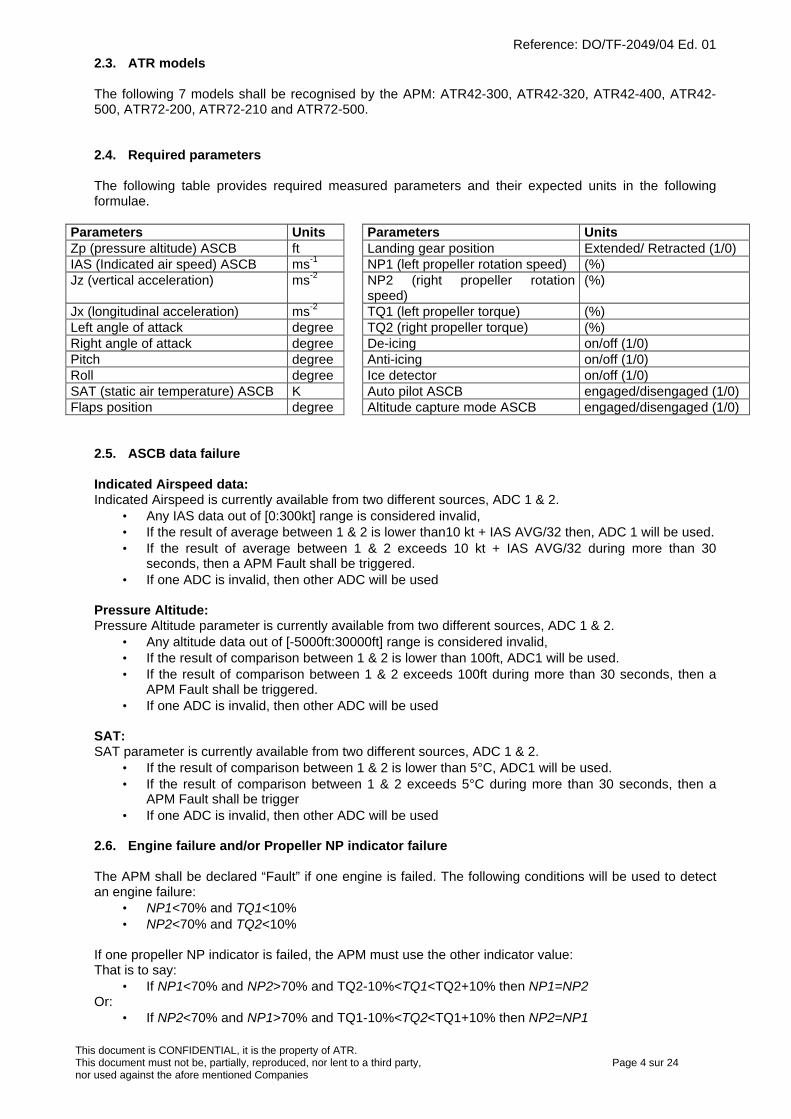
Reference: DO/TF-2049/04 Ed. 01
This document is CONFIDENTIAL, it is the property of ATR.This document must not be, partially, reproduced, nor lent to a third party, Page 4 sur 24nor used against the afore mentioned Companies
2.3. ATR models
The following 7 models shall be recognised by the APM: ATR42-300, ATR42-320, ATR42-400, ATR42-500, ATR72-200, ATR72-210 and ATR72-500.
2.4. Required parameters
The following table provides required measured parameters and their expected units in the followingformulae.
Parameters Units Parameters UnitsZp (pressure altitude) ASCB ft Landing gear position Extended/ Retracted (1/0)IAS (Indicated air speed) ASCB ms-1 NP1 (left propeller rotation speed) (%)Jz (vertical acceleration) ms-2 NP2 (right propeller rotation
speed)(%)
Jx (longitudinal acceleration) ms-2 TQ1 (left propeller torque) (%)Left angle of attack degree TQ2 (right propeller torque) (%)Right angle of attack degree De-icing on/off (1/0)Pitch degree Anti-icing on/off (1/0)Roll degree Ice detector on/off (1/0)SAT (static air temperature) ASCB K Auto pilot ASCB engaged/disengaged (1/0)Flaps position degree Altitude capture mode ASCB engaged/disengaged (1/0)
2.5. ASCB data failure
Indicated Airspeed data:Indicated Airspeed is currently available from two different sources, ADC 1 & 2.
• Any IAS data out of [0:300kt] range is considered invalid,• If the result of average between 1 & 2 is lower than10 kt + IAS AVG/32 then, ADC 1 will be used.• If the result of average between 1 & 2 exceeds 10 kt + IAS AVG/32 during more than 30
seconds, then a APM Fault shall be triggered.• If one ADC is invalid, then other ADC will be used
Pressure Altitude:Pressure Altitude parameter is currently available from two different sources, ADC 1 & 2.
• Any altitude data out of [-5000ft:30000ft] range is considered invalid,• If the result of comparison between 1 & 2 is lower than 100ft, ADC1 will be used.• If the result of comparison between 1 & 2 exceeds 100ft during more than 30 seconds, then a
APM Fault shall be triggered.• If one ADC is invalid, then other ADC will be used
SAT:SAT parameter is currently available from two different sources, ADC 1 & 2.
• If the result of comparison between 1 & 2 is lower than 5°C, ADC1 will be used.• If the result of comparison between 1 & 2 exceeds 5°C during more than 30 seconds, then a
APM Fault shall be trigger• If one ADC is invalid, then other ADC will be used
2.6. Engine failure and/or Propeller NP indicator failure
The APM shall be declared “Fault” if one engine is failed. The following conditions will be used to detectan engine failure:
• NP1<70% and TQ1<10%• NP2<70% and TQ2<10%
If one propeller NP indicator is failed, the APM must use the other indicator value:That is to say:
• If NP1<70% and NP2>70% and TQ2-10%<TQ1<TQ2+10% then NP1=NP2Or:
• If NP2<70% and NP1>70% and TQ1-10%<TQ2<TQ1+10% then NP2=NP1
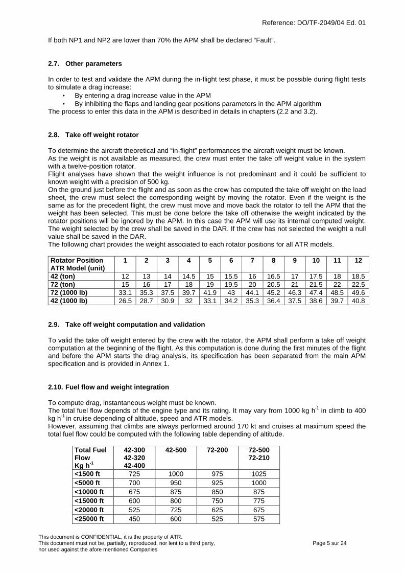
Reference: DO/TF-2049/04 Ed. 01
This document is CONFIDENTIAL, it is the property of ATR.This document must not be, partially, reproduced, nor lent to a third party, Page 5 sur 24nor used against the afore mentioned Companies
If both NP1 and NP2 are lower than 70% the APM shall be declared “Fault”.
2.7. Other parameters
In order to test and validate the APM during the in-flight test phase, it must be possible during flight teststo simulate a drag increase:
• By entering a drag increase value in the APM• By inhibiting the flaps and landing gear positions parameters in the APM algorithm
The process to enter this data in the APM is described in details in chapters (2.2 and 3.2).
2.8. Take off weight rotator
To determine the aircraft theoretical and “in-flight” performances the aircraft weight must be known.As the weight is not available as measured, the crew must enter the take off weight value in the systemwith a twelve-position rotator.Flight analyses have shown that the weight influence is not predominant and it could be sufficient toknown weight with a precision of 500 kg.On the ground just before the flight and as soon as the crew has computed the take off weight on the loadsheet, the crew must select the corresponding weight by moving the rotator. Even if the weight is thesame as for the precedent flight, the crew must move and move back the rotator to tell the APM that theweight has been selected. This must be done before the take off otherwise the weight indicated by therotator positions will be ignored by the APM. In this case the APM will use its internal computed weight.The weight selected by the crew shall be saved in the DAR. If the crew has not selected the weight a nullvalue shall be saved in the DAR.The following chart provides the weight associated to each rotator positions for all ATR models.
Rotator PositionATR Model (unit)
1 2 3 4 5 6 7 8 9 10 11 12
42 (ton) 12 13 14 14.5 15 15.5 16 16.5 17 17.5 18 18.572 (ton) 15 16 17 18 19 19.5 20 20.5 21 21.5 22 22.572 (1000 lb) 33.1 35.3 37.5 39.7 41.9 43 44.1 45.2 46.3 47.4 48.5 49.642 (1000 lb) 26.5 28.7 30.9 32 33.1 34.2 35.3 36.4 37.5 38.6 39.7 40.8
2.9. Take off weight computation and validation
To valid the take off weight entered by the crew with the rotator, the APM shall perform a take off weightcomputation at the beginning of the flight. As this computation is done during the first minutes of the flightand before the APM starts the drag analysis, its specification has been separated from the main APMspecification and is provided in Annex 1.
2.10. Fuel flow and weight integration
To compute drag, instantaneous weight must be known.The total fuel flow depends of the engine type and its rating. It may vary from 1000 kg h-1 in climb to 400kg h-1 in cruise depending of altitude, speed and ATR models.However, assuming that climbs are always performed around 170 kt and cruises at maximum speed thetotal fuel flow could be computed with the following table depending of altitude.
Total FuelFlowKg h-1
42-30042-32042-400
42-500 72-200 72-50072-210
<1500 ft 725 1000 975 1025<5000 ft 700 950 925 1000<10000 ft 675 875 850 875<15000 ft 600 800 750 775<20000 ft 525 725 625 675<25000 ft 450 600 525 575

Reference: DO/TF-2049/04 Ed. 01
This document is CONFIDENTIAL, it is the property of ATR.This document must not be, partially, reproduced, nor lent to a third party, Page 6 sur 24nor used against the afore mentioned Companies
The APM will calculate at each second the instantaneous aircraft weight from the beginning of climb up tothe landing.
Intermediate values will be interpolated.
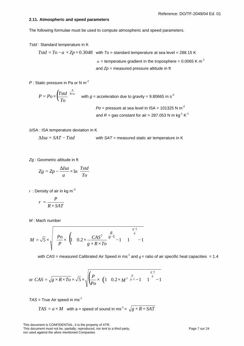
Reference: DO/TF-2049/04 Ed. 01
This document is CONFIDENTIAL, it is the property of ATR.This document must not be, partially, reproduced, nor lent to a third party, Page 7 sur 24nor used against the afore mentioned Companies
2.11. Atmospheric and speed parameters
The following formulae must be used to compute atmospheric and speed parameters.
Tstd : Standard temperature in K
3048.0××−= ZpToTstd α with To = standard temperature at sea level = 288.15 K
α = temperature gradient in the troposphere = 0.0065 K m-1
and Zp = measured pressure altitude in ft
P : Static pressure in Pa or N m-2
( )To
TstdPoPR
gα×
×= with g = acceleration due to gravity = 9.80665 m s-2
Po = pressure at sea level in ISA = 101325 N m-2
and R = gas constant for air = 287.053 N m kg-1 K-1
∆ISA : ISA temperature deviation in K
TstdSATIsa −=∆ with SAT = measured static air temperature in K
Zg : Geometric altitude in ft
×
∆−=
ToTstdIsa
ZpZg lnα
ρ : Density of air in kg m-3
SATRP
×=ρ
M : Mach number
( ) 1112.0152
1
1−+
−
×××+××=
−
−
ToRCAS
PPo
Mγ
γγ γ
γ
with CAS = measured Calibrated Air Speed in ms-1 and γ = ratio of air specific heat capacities = 1.4
or ( )( ) 1112.015 2 1
1
−+
−×+×××××= −
−
MPoP
ToRCAS γγ γ
γ
γ
TAS = True Air speed in ms-1
MaTAS ×= with a = speed of sound in ms-1 = SATR ××γ
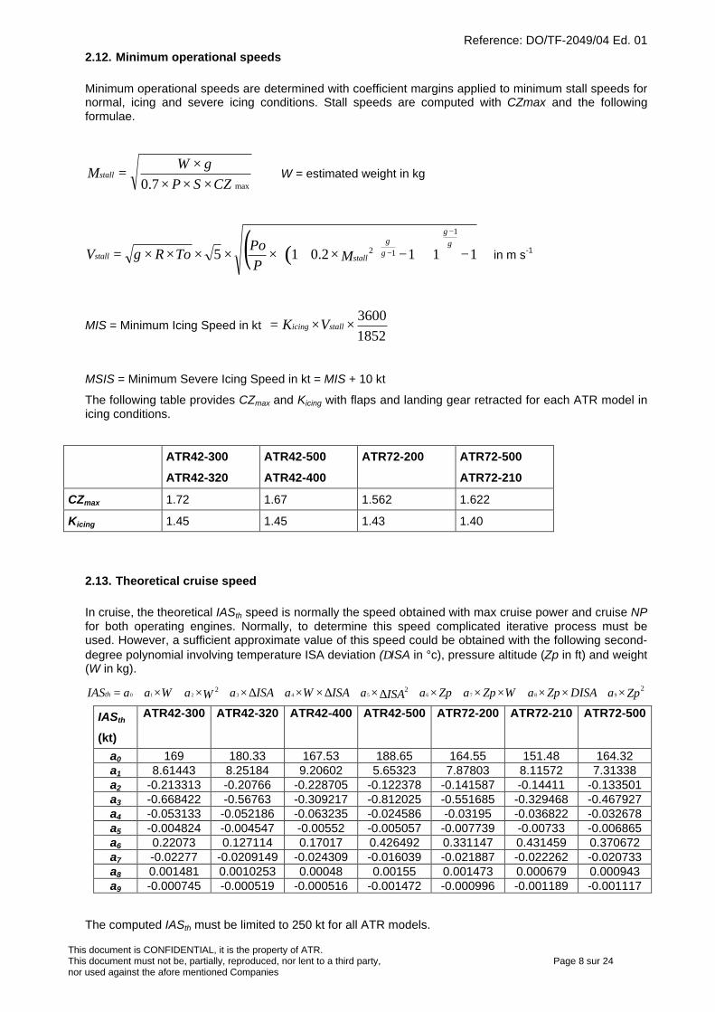
Reference: DO/TF-2049/04 Ed. 01
This document is CONFIDENTIAL, it is the property of ATR.This document must not be, partially, reproduced, nor lent to a third party, Page 8 sur 24nor used against the afore mentioned Companies
2.12. Minimum operational speeds
Minimum operational speeds are determined with coefficient margins applied to minimum stall speeds fornormal, icing and severe icing conditions. Stall speeds are computed with CZmax and the followingformulae.
max7.0 CZSPgW
Mstall×××
×= W = estimated weight in kg
( )( ) 1112.015 2 1
1
−+
−×+×××××= −
−
stallstall MPPo
ToRV γγ γ
γ
γ in m s-1
MIS = Minimum Icing Speed in kt 18523600
××= stallicing VK
MSIS = Minimum Severe Icing Speed in kt = MIS + 10 kt
The following table provides CZmax and Kicing with flaps and landing gear retracted for each ATR model inicing conditions.
ATR42-300
ATR42-320
ATR42-500
ATR42-400
ATR72-200 ATR72-500
ATR72-210
CZmax 1.72 1.67 1.562 1.622
Kicing 1.45 1.45 1.43 1.40
2.13. Theoretical cruise speed
In cruise, the theoretical IASth speed is normally the speed obtained with max cruise power and cruise NPfor both operating engines. Normally, to determine this speed complicated iterative process must beused. However, a sufficient approximate value of this speed could be obtained with the following second-degree polynomial involving temperature ISA deviation (∆ISA in °c), pressure altitude (Zp in ft) and weight(W in kg).
ZpaDISAZpaWZpaZpaISAaISAWaISAaWaWaaIASth222
9876543210 ×+××+××+×+∆×+∆××+∆×+×+×+=
IASth
(kt)
ATR42-300 ATR42-320 ATR42-400 ATR42-500 ATR72-200 ATR72-210 ATR72-500
a0 169 180.33 167.53 188.65 164.55 151.48 164.32a1 8.61443 8.25184 9.20602 5.65323 7.87803 8.11572 7.31338a2 -0.213313 -0.20766 -0.228705 -0.122378 -0.141587 -0.14411 -0.133501a3 -0.668422 -0.56763 -0.309217 -0.812025 -0.551685 -0.329468 -0.467927a4 -0.053133 -0.052186 -0.063235 -0.024586 -0.03195 -0.036822 -0.032678a5 -0.004824 -0.004547 -0.00552 -0.005057 -0.007739 -0.00733 -0.006865a6 0.22073 0.127114 0.17017 0.426492 0.331147 0.431459 0.370672a7 -0.02277 -0.0209149 -0.024309 -0.016039 -0.021887 -0.022262 -0.020733a8 0.001481 0.0010253 0.00048 0.00155 0.001473 0.000679 0.000943a9 -0.000745 -0.000519 -0.000516 -0.001472 -0.000996 -0.001189 -0.001117
The computed IASth must be limited to 250 kt for all ATR models.
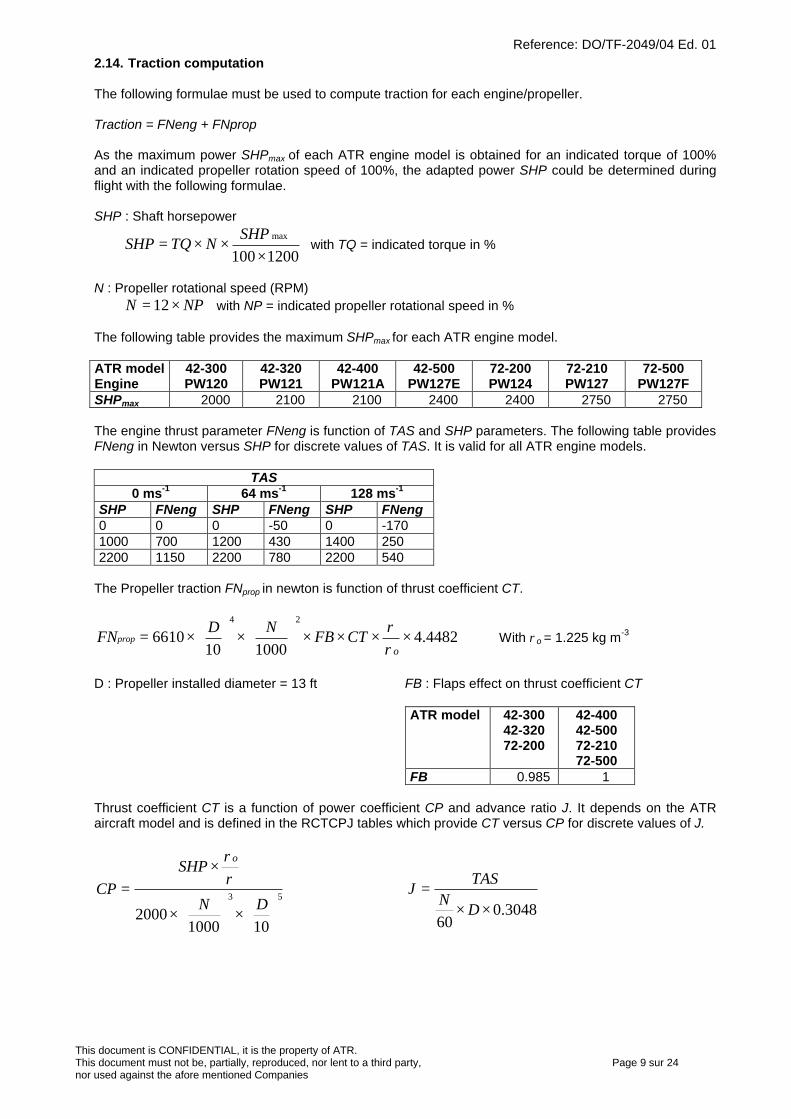
Reference: DO/TF-2049/04 Ed. 01
This document is CONFIDENTIAL, it is the property of ATR.This document must not be, partially, reproduced, nor lent to a third party, Page 9 sur 24nor used against the afore mentioned Companies
2.14. Traction computation
The following formulae must be used to compute traction for each engine/propeller.
Traction = FNeng + FNprop
As the maximum power SHPmax of each ATR engine model is obtained for an indicated torque of 100%and an indicated propeller rotation speed of 100%, the adapted power SHP could be determined duringflight with the following formulae.
SHP : Shaft horsepower
1200100 max
×××=
SHPNTQSHP with TQ = indicated torque in %
N : Propeller rotational speed (RPM)NPN ×= 12 with NP = indicated propeller rotational speed in %
The following table provides the maximum SHPmax for each ATR engine model.
ATR modelEngine
42-300PW120
42-320PW121
42-400PW121A
42-500PW127E
72-200PW124
72-210PW127
72-500PW127F
SHPmax 2000 2100 2100 2400 2400 2750 2750
The engine thrust parameter FNeng is function of TAS and SHP parameters. The following table providesFNeng in Newton versus SHP for discrete values of TAS. It is valid for all ATR engine models.
TAS0 ms-1 64 ms-1 128 ms-1
SHP FNeng SHP FNeng SHP FNeng0 0 0 -50 0 -1701000 700 1200 430 1400 2502200 1150 2200 780 2200 540
The Propeller traction FNprop in newton is function of thrust coefficient CT.
4482.4100010
661024
××××
×
×=
oCTFB
NDFNprop
ρρ
With ρo = 1.225 kg m-3
D : Propeller installed diameter = 13 ft FB : Flaps effect on thrust coefficient CT
ATR model 42-30042-32072-200
42-40042-50072-21072-500
FB 0.985 1
Thrust coefficient CT is a function of power coefficient CP and advance ratio J. It depends on the ATRaircraft model and is defined in the RCTCPJ tables which provide CT versus CP for discrete values of J.
×
×
×=
1010002000
53DN
SHPCP
o
ρρ
3048.060
××=
DN
TASJ
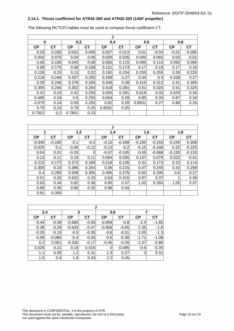
Reference: DO/TF-2049/04 Ed. 01
This document is CONFIDENTIAL, it is the property of ATR.This document must not be, partially, reproduced, nor lent to a third party, Page 10 sur 24nor used against the afore mentioned Companies
2.14.1. Thrust coefficient for ATR42-300 and ATR42-320 (14SF propeller)
The following RCTCPJ tables must be used to compute thrust coefficient CT.
J0 0.2 0.4 0.6 0.8
CP CT CP CT CP CT CP CT CP CT0.03 0.035 0.031 0.005 0.027 0.013 0.01 -0.03 -0.01 -0.095
0.042 0.075 0.04 0.06 0.029 0.035 0.045 0.065 0.02 -0.010.05 0.105 0.043 0.08 0.065 0.115 0.095 0.115 0.092 0.0950.09 0.175 0.08 0.158 0.121 0.173 0.17 0.19 0.17 0.16
0.135 0.23 0.13 0.22 0.192 0.234 0.255 0.255 0.26 0.2250.216 0.246 0.207 0.255 0.268 0.27 0.34 0.3 0.328 0.27
0.29 0.246 0.278 0.265 0.349 0.28 0.415 0.312 0.41 0.3050.355 0.245 0.352 0.264 0.418 0.281 0.51 0.325 0.51 0.325
0.42 0.24 0.42 0.255 0.505 0.281 0.616 0.33 0.625 0.340.495 0.24 0.5 0.255 0.604 0.29 0.85 0.33 0.87 0.340.575 0.24 0.59 0.255 0.82 0.29 0.8501 0.27 0.88 0.29
0.75 0.23 0.78 0.25 0.8201 0.250.7501 0.2 0.7801 0.23
J1 1.2 1.4 1.6 1.8
CP CT CP CT CP CT CP CT CP CT-0.045 -0.165 -0.1 -0.2 -0.15 -0.268 -0.195 -0.255 -0.245 -0.308-0.025 -0.1 -0.06 -0.12 -0.13 -0.2 -0.15 -0.168 -0.22 -0.225
0.04 0.01 -0.03 0 -0.07 -0.105 -0.05 -0.068 -0.135 -0.1330.13 0.11 0.15 0.11 0.064 0.035 0.137 0.075 0.022 -0.01
0.215 0.172 0.272 0.189 0.218 0.135 0.31 0.173 0.23 0.1140.305 0.23 0.386 0.254 0.36 0.215 0.47 0.245 0.42 0.208
0.4 0.285 0.508 0.305 0.495 0.275 0.62 0.295 0.6 0.270.51 0.32 0.632 0.33 0.63 0.315 0.97 0.37 1 0.360.63 0.34 0.92 0.36 0.95 0.37 1.02 0.355 1.05 0.370.89 0.35 0.95 0.32 0.98 0.340.91 0.305
J2.4 3 3.6 7
CP CT CP CT CP CT CP CT-0.44 -0.39 -0.685 -0.59 -0.959 -0.8 -2.4 -1.85-0.38 -0.29 -0.643 -0.47 -0.958 -0.65 -2.35 -1.6-0.25 -0.19 -0.5 -0.35 -0.8 -0.51 -2.05 -1.3-0.09 -0.085 -0.4 -0.25 -0.6 -0.38 -1.71 -1.08
0.2 0.061 -0.335 -0.17 -0.45 -0.25 -1.37 -0.860.525 0.21 0.19 0.015 0 -0.095 -0.6 -0.35
1.1 0.35 1.2 0.31 1.3 0.27 3 0.311.5 0.4 1.9 0.43 2.2 0.45
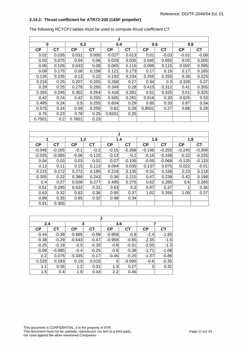
Reference: DO/TF-2049/04 Ed. 01
This document is CONFIDENTIAL, it is the property of ATR.This document must not be, partially, reproduced, nor lent to a third party, Page 11 sur 24nor used against the afore mentioned Companies
2.14.2. Thrust coefficient for ATR72-200 (14SF propeller)
The following RCTCPJ tables must be used to compute thrust coefficient CT.
J0 0.2 0.4 0.6 0.8
CP CT CP CT CP CT CP CT CP CT0.02 0.035 0.031 0.005 0.027 0.013 0.01 -0.03 -0.01 -0.080.03 0.075 0.04 0.06 0.029 0.035 0.045 0.065 0.02 0.0050.05 0.105 0.043 0.08 0.065 0.115 0.095 0.115 0.092 0.0950.09 0.175 0.08 0.158 0.121 0.173 0.17 0.19 0.17 0.165
0.135 0.235 0.13 0.22 0.192 0.234 0.255 0.255 0.26 0.2250.216 0.25 0.207 0.255 0.268 0.27 0.34 0.3 0.328 0.27
0.29 0.25 0.278 0.265 0.349 0.28 0.415 0.312 0.41 0.3050.355 0.245 0.352 0.264 0.418 0.281 0.51 0.325 0.51 0.325
0.42 0.24 0.42 0.255 0.505 0.281 0.616 0.33 0.625 0.330.495 0.24 0.5 0.255 0.604 0.29 0.85 0.33 0.87 0.340.575 0.24 0.59 0.255 0.82 0.29 0.8501 0.27 0.88 0.29
0.75 0.23 0.78 0.25 0.8201 0.250.7501 0.2 0.7801 0.23
J1 1.2 1.4 1.6 1.8
CP CT CP CT CP CT CP CT CP CT-0.045 -0.165 -0.1 -0.2 -0.15 -0.268 -0.195 -0.255 -0.245 -0.308-0.025 -0.085 -0.06 -0.115 -0.13 -0.2 -0.15 -0.168 -0.22 -0.225
0.04 0.03 0.03 0.01 -0.07 -0.105 -0.05 -0.068 -0.135 -0.1330.13 0.11 0.15 0.113 0.064 0.035 0.137 0.075 0.022 -0.01
0.215 0.172 0.272 0.185 0.218 0.135 0.31 0.168 0.23 0.1180.305 0.22 0.386 0.243 0.36 0.215 0.47 0.239 0.42 0.198
0.4 0.27 0.508 0.277 0.495 0.275 0.62 0.285 0.6 0.2650.51 0.295 0.632 0.31 0.63 0.3 0.97 0.37 1 0.360.63 0.32 0.92 0.36 0.95 0.37 1.02 0.355 1.05 0.370.89 0.35 0.95 0.32 0.98 0.340.91 0.305
J2.4 3 3.6 7
CP CT CP CT CP CT CP CT-0.44 -0.39 -0.685 -0.59 -0.959 -0.8 -2.4 -1.85-0.38 -0.29 -0.643 -0.47 -0.958 -0.65 -2.35 -1.6-0.25 -0.19 -0.5 -0.35 -0.8 -0.51 -2.05 -1.3-0.09 -0.085 -0.4 -0.25 -0.6 -0.38 -1.71 -1.08
0.2 0.075 -0.335 -0.17 -0.45 -0.25 -1.37 -0.860.525 0.193 0.19 0.015 0 -0.095 -0.6 -0.35
1.1 0.35 1.2 0.31 1.3 0.27 3 0.311.5 0.4 1.9 0.43 2.2 0.45
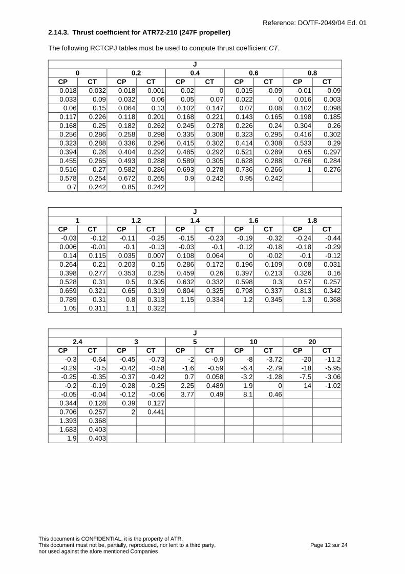
Reference: DO/TF-2049/04 Ed. 01
This document is CONFIDENTIAL, it is the property of ATR.This document must not be, partially, reproduced, nor lent to a third party, Page 12 sur 24nor used against the afore mentioned Companies
2.14.3. Thrust coefficient for ATR72-210 (247F propeller)
The following RCTCPJ tables must be used to compute thrust coefficient CT.
J0 0.2 0.4 0.6 0.8
CP CT CP CT CP CT CP CT CP CT0.018 0.032 0.018 0.001 0.02 0 0.015 -0.09 -0.01 -0.090.033 0.09 0.032 0.06 0.05 0.07 0.022 0 0.016 0.003
0.06 0.15 0.064 0.13 0.102 0.147 0.07 0.08 0.102 0.0980.117 0.226 0.118 0.201 0.168 0.221 0.143 0.165 0.198 0.1850.168 0.25 0.182 0.262 0.245 0.278 0.226 0.24 0.304 0.260.256 0.286 0.258 0.298 0.335 0.308 0.323 0.295 0.416 0.3020.323 0.288 0.336 0.296 0.415 0.302 0.414 0.308 0.533 0.290.394 0.28 0.404 0.292 0.485 0.292 0.521 0.289 0.65 0.2970.455 0.265 0.493 0.288 0.589 0.305 0.628 0.288 0.766 0.2840.516 0.27 0.582 0.286 0.693 0.278 0.736 0.266 1 0.2760.578 0.254 0.672 0.265 0.9 0.242 0.95 0.242
0.7 0.242 0.85 0.242
J1 1.2 1.4 1.6 1.8
CP CT CP CT CP CT CP CT CP CT-0.03 -0.12 -0.11 -0.25 -0.15 -0.23 -0.19 -0.32 -0.24 -0.440.006 -0.01 -0.1 -0.13 -0.03 -0.1 -0.12 -0.18 -0.18 -0.29
0.14 0.115 0.035 0.007 0.108 0.064 0 -0.02 -0.1 -0.120.264 0.21 0.203 0.15 0.286 0.172 0.196 0.109 0.08 0.0310.398 0.277 0.353 0.235 0.459 0.26 0.397 0.213 0.326 0.160.528 0.31 0.5 0.305 0.632 0.332 0.598 0.3 0.57 0.2570.659 0.321 0.65 0.319 0.804 0.325 0.798 0.337 0.813 0.3420.789 0.31 0.8 0.313 1.15 0.334 1.2 0.345 1.3 0.368
1.05 0.311 1.1 0.322
J2.4 3 5 10 20
CP CT CP CT CP CT CP CT CP CT-0.3 -0.64 -0.45 -0.73 -2 -0.9 -8 -3.72 -20 -11.2
-0.29 -0.5 -0.42 -0.58 -1.6 -0.59 -6.4 -2.79 -18 -5.95-0.25 -0.35 -0.37 -0.42 0.7 0.058 -3.2 -1.28 -7.5 -3.06-0.2 -0.19 -0.28 -0.25 2.25 0.489 1.9 0 14 -1.02
-0.05 -0.04 -0.12 -0.06 3.77 0.49 8.1 0.460.344 0.128 0.39 0.1270.706 0.257 2 0.4411.393 0.3681.683 0.403
1.9 0.403
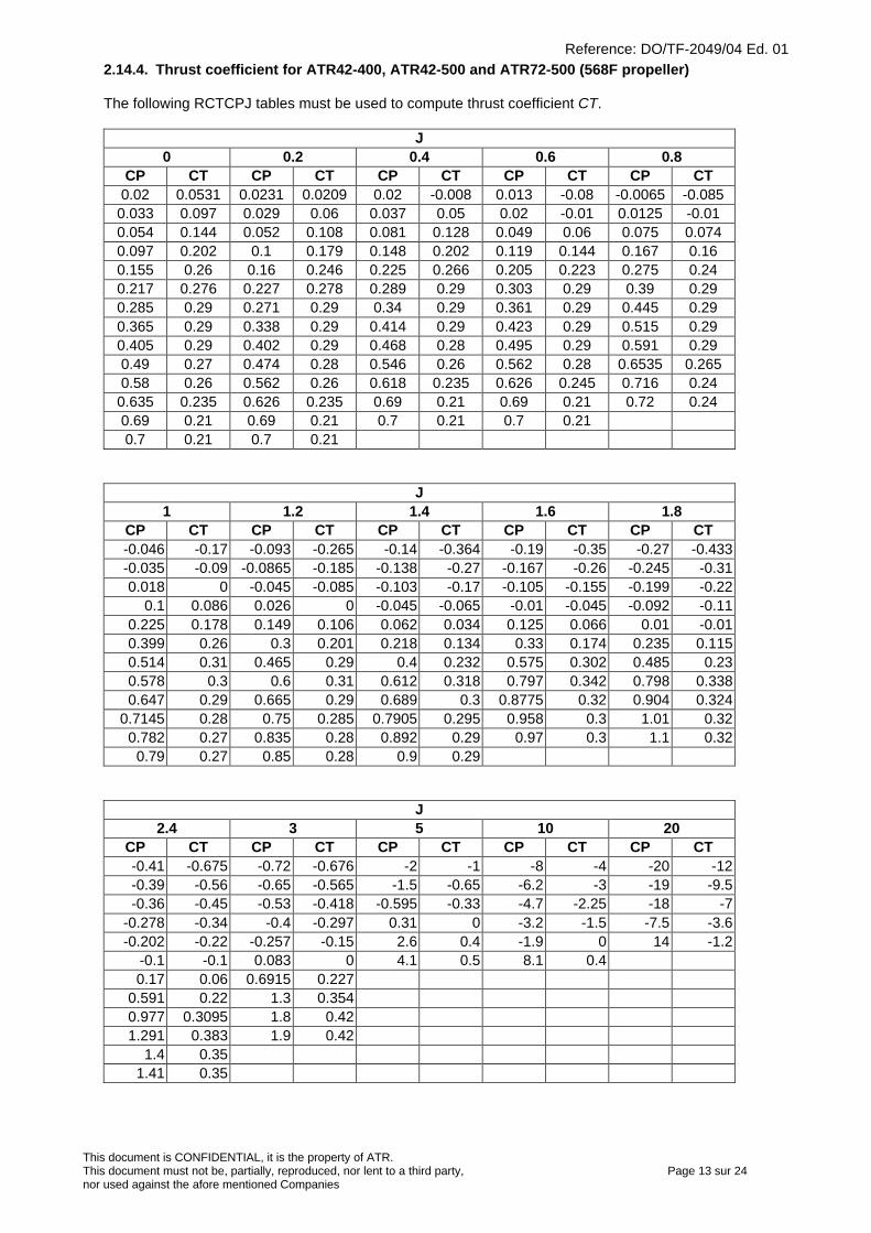
Reference: DO/TF-2049/04 Ed. 01
This document is CONFIDENTIAL, it is the property of ATR.This document must not be, partially, reproduced, nor lent to a third party, Page 13 sur 24nor used against the afore mentioned Companies
2.14.4. Thrust coefficient for ATR42-400, ATR42-500 and ATR72-500 (568F propeller)
The following RCTCPJ tables must be used to compute thrust coefficient CT.
J0 0.2 0.4 0.6 0.8
CP CT CP CT CP CT CP CT CP CT0.02 0.0531 0.0231 0.0209 0.02 -0.008 0.013 -0.08 -0.0065 -0.0850.033 0.097 0.029 0.06 0.037 0.05 0.02 -0.01 0.0125 -0.010.054 0.144 0.052 0.108 0.081 0.128 0.049 0.06 0.075 0.0740.097 0.202 0.1 0.179 0.148 0.202 0.119 0.144 0.167 0.160.155 0.26 0.16 0.246 0.225 0.266 0.205 0.223 0.275 0.240.217 0.276 0.227 0.278 0.289 0.29 0.303 0.29 0.39 0.290.285 0.29 0.271 0.29 0.34 0.29 0.361 0.29 0.445 0.290.365 0.29 0.338 0.29 0.414 0.29 0.423 0.29 0.515 0.290.405 0.29 0.402 0.29 0.468 0.28 0.495 0.29 0.591 0.290.49 0.27 0.474 0.28 0.546 0.26 0.562 0.28 0.6535 0.2650.58 0.26 0.562 0.26 0.618 0.235 0.626 0.245 0.716 0.240.635 0.235 0.626 0.235 0.69 0.21 0.69 0.21 0.72 0.240.69 0.21 0.69 0.21 0.7 0.21 0.7 0.210.7 0.21 0.7 0.21
J1 1.2 1.4 1.6 1.8
CP CT CP CT CP CT CP CT CP CT-0.046 -0.17 -0.093 -0.265 -0.14 -0.364 -0.19 -0.35 -0.27 -0.433-0.035 -0.09 -0.0865 -0.185 -0.138 -0.27 -0.167 -0.26 -0.245 -0.310.018 0 -0.045 -0.085 -0.103 -0.17 -0.105 -0.155 -0.199 -0.22
0.1 0.086 0.026 0 -0.045 -0.065 -0.01 -0.045 -0.092 -0.110.225 0.178 0.149 0.106 0.062 0.034 0.125 0.066 0.01 -0.010.399 0.26 0.3 0.201 0.218 0.134 0.33 0.174 0.235 0.1150.514 0.31 0.465 0.29 0.4 0.232 0.575 0.302 0.485 0.230.578 0.3 0.6 0.31 0.612 0.318 0.797 0.342 0.798 0.3380.647 0.29 0.665 0.29 0.689 0.3 0.8775 0.32 0.904 0.324
0.7145 0.28 0.75 0.285 0.7905 0.295 0.958 0.3 1.01 0.320.782 0.27 0.835 0.28 0.892 0.29 0.97 0.3 1.1 0.32
0.79 0.27 0.85 0.28 0.9 0.29
J2.4 3 5 10 20
CP CT CP CT CP CT CP CT CP CT-0.41 -0.675 -0.72 -0.676 -2 -1 -8 -4 -20 -12-0.39 -0.56 -0.65 -0.565 -1.5 -0.65 -6.2 -3 -19 -9.5-0.36 -0.45 -0.53 -0.418 -0.595 -0.33 -4.7 -2.25 -18 -7
-0.278 -0.34 -0.4 -0.297 0.31 0 -3.2 -1.5 -7.5 -3.6-0.202 -0.22 -0.257 -0.15 2.6 0.4 -1.9 0 14 -1.2
-0.1 -0.1 0.083 0 4.1 0.5 8.1 0.40.17 0.06 0.6915 0.227
0.591 0.22 1.3 0.3540.977 0.3095 1.8 0.421.291 0.383 1.9 0.42
1.4 0.351.41 0.35
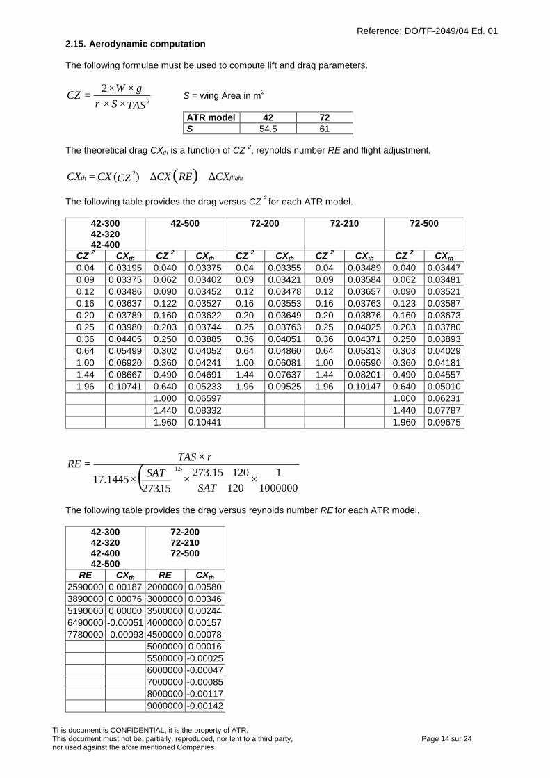
Reference: DO/TF-2049/04 Ed. 01
This document is CONFIDENTIAL, it is the property of ATR.This document must not be, partially, reproduced, nor lent to a third party, Page 14 sur 24nor used against the afore mentioned Companies
2.15. Aerodynamic computation
The following formulae must be used to compute lift and drag parameters.
TASSgW
CZ2
2××
××=
ρS = wing Area in m2
ATR model 42 72S 54.5 61
The theoretical drag CXth is a function of CZ 2, reynolds number RE and flight adjustment.
flightth CXRECXCZCXCX ∆+∆+= )()( 2
The following table provides the drag versus CZ 2 for each ATR model.
42-30042-32042-400
42-500 72-200 72-210 72-500
CZ 2 CXth CZ 2 CXth CZ 2 CXth CZ 2 CXth CZ 2 CXth
0.04 0.03195 0.040 0.03375 0.04 0.03355 0.04 0.03489 0.040 0.034470.09 0.03375 0.062 0.03402 0.09 0.03421 0.09 0.03584 0.062 0.034810.12 0.03486 0.090 0.03452 0.12 0.03478 0.12 0.03657 0.090 0.035210.16 0.03637 0.122 0.03527 0.16 0.03553 0.16 0.03763 0.123 0.035870.20 0.03789 0.160 0.03622 0.20 0.03649 0.20 0.03876 0.160 0.036730.25 0.03980 0.203 0.03744 0.25 0.03763 0.25 0.04025 0.203 0.037800.36 0.04405 0.250 0.03885 0.36 0.04051 0.36 0.04371 0.250 0.038930.64 0.05499 0.302 0.04052 0.64 0.04860 0.64 0.05313 0.303 0.040291.00 0.06920 0.360 0.04241 1.00 0.06081 1.00 0.06590 0.360 0.041811.44 0.08667 0.490 0.04691 1.44 0.07637 1.44 0.08201 0.490 0.045571.96 0.10741 0.640 0.05233 1.96 0.09525 1.96 0.10147 0.640 0.05010
1.000 0.06597 1.000 0.062311.440 0.08332 1.440 0.077871.960 0.10441 1.960 0.09675
( )1000000
112012015.273
152731445.17
51
×++
××
×=
SAT.SAT
TASRE .
ρ
The following table provides the drag versus reynolds number RE for each ATR model.
42-30042-32042-40042-500
72-20072-21072-500
RE CXth RE CXth
2590000 0.00187 2000000 0.005803890000 0.00076 3000000 0.003465190000 0.00000 3500000 0.002446490000 -0.00051 4000000 0.001577780000 -0.00093 4500000 0.00078
5000000 0.000165500000 -0.000256000000 -0.000477000000 -0.000858000000 -0.001179000000 -0.00142
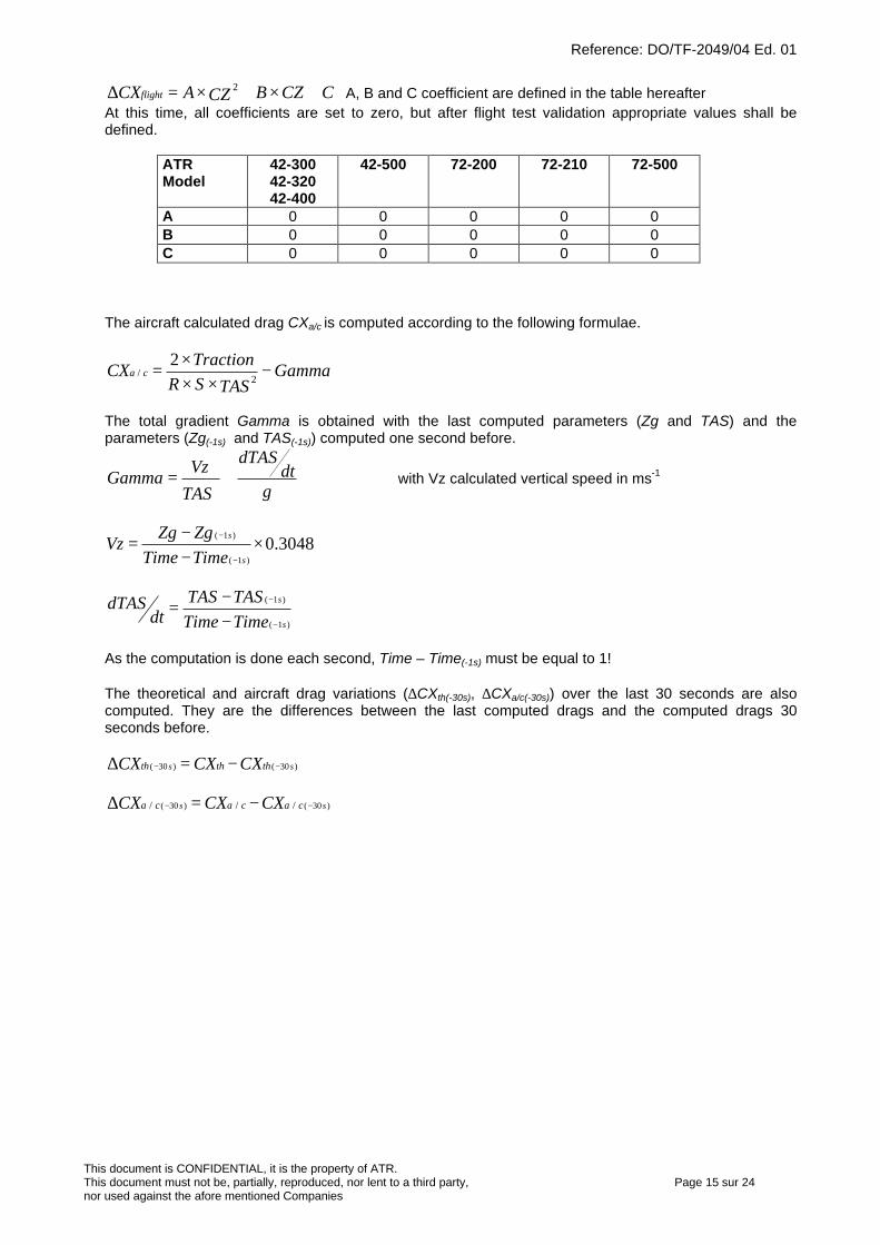
Reference: DO/TF-2049/04 Ed. 01
This document is CONFIDENTIAL, it is the property of ATR.This document must not be, partially, reproduced, nor lent to a third party, Page 15 sur 24nor used against the afore mentioned Companies
CCZBCZACXflight +×+×=∆ 2 A, B and C coefficient are defined in the table hereafterAt this time, all coefficients are set to zero, but after flight test validation appropriate values shall bedefined.
ATRModel
42-30042-32042-400
42-500 72-200 72-210 72-500
A 0 0 0 0 0B 0 0 0 0 0C 0 0 0 0 0
The aircraft calculated drag CXa/c is computed according to the following formulae.
GammaTASSR
TractionCX ca −
×××
=2
/2
The total gradient Gamma is obtained with the last computed parameters (Zg and TAS) and theparameters (Zg(-1s) and TAS(-1s)) computed one second before.
gdt
dTAS
TAS
VzGamma += with Vz calculated vertical speed in ms-1
3048.0)1(
)1(×
−−
=−
−
s
s
TimeTimeZgZg
Vz
)1(
)1(
s
s
TimeTimeTASTAS
dtdTAS
−
−
−−
=
As the computation is done each second, Time – Time(-1s) must be equal to 1!
The theoretical and aircraft drag variations (∆CXth(-30s), ∆CXa/c(-30s)) over the last 30 seconds are alsocomputed. They are the differences between the last computed drags and the computed drags 30seconds before.
)30()30( ss ththth CXCXCX −− −=∆
)30()30( /// ss cacaca CXCXCX −− −=∆
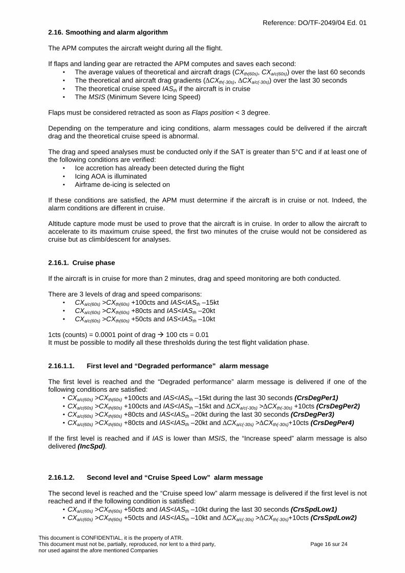
Reference: DO/TF-2049/04 Ed. 01
This document is CONFIDENTIAL, it is the property of ATR.This document must not be, partially, reproduced, nor lent to a third party, Page 16 sur 24nor used against the afore mentioned Companies
2.16. Smoothing and alarm algorithm
The APM computes the aircraft weight during all the flight.
If flaps and landing gear are retracted the APM computes and saves each second:• The average values of theoretical and aircraft drags (CXth(60s), CXa/c(60s)) over the last 60 seconds• The theoretical and aircraft drag gradients (∆CXth(-30s), ∆CXa/c(-30s)) over the last 30 seconds• The theoretical cruise speed IASth if the aircraft is in cruise• The MSIS (Minimum Severe Icing Speed)
Flaps must be considered retracted as soon as Flaps position < 3 degree.
Depending on the temperature and icing conditions, alarm messages could be delivered if the aircraftdrag and the theoretical cruise speed is abnormal.
The drag and speed analyses must be conducted only if the SAT is greater than 5°C and if at least one ofthe following conditions are verified:
• Ice accretion has already been detected during the flight• Icing AOA is illuminated• Airframe de-icing is selected on
If these conditions are satisfied, the APM must determine if the aircraft is in cruise or not. Indeed, thealarm conditions are different in cruise.
Altitude capture mode must be used to prove that the aircraft is in cruise. In order to allow the aircraft toaccelerate to its maximum cruise speed, the first two minutes of the cruise would not be considered ascruise but as climb/descent for analyses.
2.16.1. Cruise phase
If the aircraft is in cruise for more than 2 minutes, drag and speed monitoring are both conducted.
There are 3 levels of drag and speed comparisons:• CXa/c(60s) >CXth(60s) +100cts and IAS<IASth –15kt• CXa/c(60s) >CXth(60s) +80cts and IAS<IASth –20kt• CXa/c(60s) >CXth(60s) +50cts and IAS<IASth –10kt
1cts (counts) = 0.0001 point of drag à 100 cts = 0.01It must be possible to modify all these thresholds during the test flight validation phase.
2.16.1.1. First level and “Degraded performance” alarm message
The first level is reached and the “Degraded performance” alarm message is delivered if one of thefollowing conditions are satisfied:
• CXa/c(60s) >CXth(60s) +100cts and IAS<IASth –15kt during the last 30 seconds (CrsDegPer1)• CXa/c(60s) >CXth(60s) +100cts and IAS<IASth –15kt and ∆CXa/c(-30s) >∆CXth(-30s) +10cts (CrsDegPer2)• CXa/c(60s) >CXth(60s) +80cts and IAS<IASth –20kt during the last 30 seconds (CrsDegPer3)• CXa/c(60s) >CXth(60s) +80cts and IAS<IASth –20kt and ∆CXa/c(-30s) >∆CXth(-30s)+10cts (CrsDegPer4)
If the first level is reached and if IAS is lower than MSIS, the “Increase speed” alarm message is alsodelivered (IncSpd).
2.16.1.2. Second level and “Cruise Speed Low” alarm message
The second level is reached and the “Cruise speed low” alarm message is delivered if the first level is notreached and if the following condition is satisfied:
• CXa/c(60s) >CXth(60s) +50cts and IAS<IASth –10kt during the last 30 seconds (CrsSpdLow1)• CXa/c(60s) >CXth(60s) +50cts and IAS<IASth –10kt and ∆CXa/c(-30s) >∆CXth(-30s)+10cts (CrsSpdLow2)
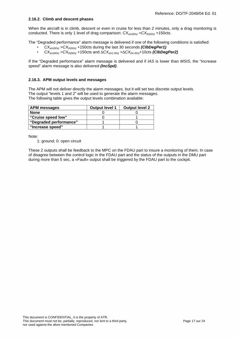
Reference: DO/TF-2049/04 Ed. 01
This document is CONFIDENTIAL, it is the property of ATR.This document must not be, partially, reproduced, nor lent to a third party, Page 17 sur 24nor used against the afore mentioned Companies
2.16.2. Climb and descent phases
When the aircraft is in climb, descent or even in cruise for less than 2 minutes, only a drag monitoring isconducted. There is only 1 level of drag comparison: CXa/c(60s) >CXth(60s) +150cts.
The “Degraded performance” alarm message is delivered if one of the following conditions is satisfied:• CXa/c(60s) >CXth(60s) +150cts during the last 30 seconds (ClbDegPer1)• CXa/c(60s) >CXth(60s) +150cts and ∆CXa/c(-30s) >∆CXth(-30s)+10cts (ClbDegPer2)
If the “Degraded performance” alarm message is delivered and if IAS is lower than MSIS, the “Increasespeed” alarm message is also delivered (IncSpd).
2.16.3. APM output levels and messages
The APM will not deliver directly the alarm messages, but it will set two discrete output levels.The output “levels 1 and 2” will be used to generate the alarm messages.The following table gives the output levels combination available:
APM messages Output level 1 Output level 2None 0 0“Cruise speed low” 0 1“Degraded performance” 1 0“Increase speed” 1 1
Note:1: ground; 0: open circuit
These 2 outputs shall be feedback to the MPC on the FDAU part to insure a monitoring of them. In caseof disagree between the control logic in the FDAU part and the status of the outputs in the DMU partduring more than 5 sec, a «Fault» output shall be triggered by the FDAU part to the cockpit.
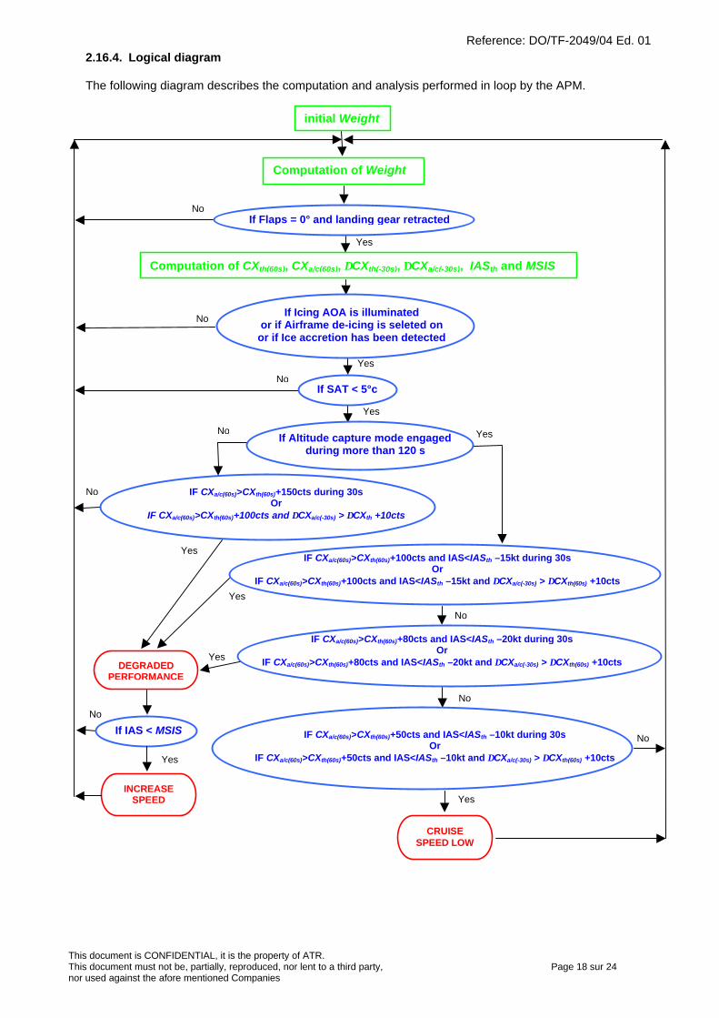
Reference: DO/TF-2049/04 Ed. 01
This document is CONFIDENTIAL, it is the property of ATR.This document must not be, partially, reproduced, nor lent to a third party, Page 18 sur 24nor used against the afore mentioned Companies
2.16.4. Logical diagram
The following diagram describes the computation and analysis performed in loop by the APM.
Computation of Weight
initial Weight
IF CXa/c(60s)>CXth(60s)+150cts during 30sOr
IF CXa/c(60s)>CXth(60s)+100cts and ∆CXa/c(-30s) > ∆CXth +10cts
IF CXa/c(60s)>CXth(60s)+100cts and IAS<IASth –15kt during 30sOr
IF CXa/c(60s)>CXth(60s)+100cts and IAS<IASth –15kt and ∆CXa/c(-30s) > ∆CXth(60s) +10cts
Computation of CXth(60s), CXa/c(60s), ∆CXth(-30s), ∆CXa/c(-30s), IASth and MSIS
INCREASESPEED
Yes
Yes
No
Yes
No
No
No
DEGRADEDPERFORMANCE
Yes
Yes
No
Yes
CRUISESPEED LOW
Yes
No
No
Yes
No
If Flaps = 0° and landing gear retracted
If SAT < 5°cNo
Yes
If Altitude capture mode engagedduring more than 120 s
IF CXa/c(60s)>CXth(60s)+50cts and IAS<IASth –10kt during 30sOr
IF CXa/c(60s)>CXth(60s)+50cts and IAS<IASth –10kt and ∆CXa/c(-30s) > ∆CXth(60s) +10cts
If IAS < MSIS
If Icing AOA is illuminatedor if Airframe de-icing is seleted on
or if Ice accretion has been detected
IF CXa/c(60s)>CXth(60s)+80cts and IAS<IASth –20kt during 30sOr
IF CXa/c(60s)>CXth(60s)+80cts and IAS<IASth –20kt and ∆CXa/c(-30s) > ∆CXth(60s) +10cts
Reference: DO/TF-2049/04 Ed. 01
This document is CONFIDENTIAL, it is the property of ATR.This document must not be, partially, reproduced, nor lent to a third party, Page 19 sur 24nor used against the afore mentioned Companies
3. Validation
3.1. APM validation before flight tests
The APM must be validated using input DFDR or QAR/DAR data that represent real flights for each ATRmodel.The APM must provide the same results as our internal APM simulator.To ease the validation, the APM must save the measured parameters and the following calculatedparameters function of time with a period of one second in the DAR:
• Rotator weight (kg)• Weight (kg)• CZ• CXth(60s) (counts)• CXa/c(60s) (counts)
• IASth(kt)• MSIS (kt)• “Level 1” output• “Level 2” output• “Level 3” output
Additionally, the following internal computation parameters shall be useful to eliminate any discrepanciesbetween the APM drag computations and our APM simulator drag results:
• TAS(kt)• Gamma• Traction
These additional parameters shall be also saved in the DAR.
ATR will provide the input data for the following test cases:• QAR data of MSN 214 (ATR42-300) : 38 flights• QAR data of MSN 461 (ATR72-210) : 31 flights• QAR data of MSN 214 (ATR72-200) : 12 flights• DFDR data of MSN 514 (ATR42-500) : 53 flights• DFDR data of JET AIRWAYS (ATR72-500) : 13 flights
ATR will validate the APM using DAR data generated for those test cases using SAGEM AGS softwareand our internal APM simulator.
However, our APM simulator output results will be provided for two selected flights per ATR model as acomma-separated value file format or a Microsoft Excel file giving the following parameters:
• Time (s)• Weight (kg)• Zp (ft)• Delta ISA• Mach• IAS (kt)• TAS (kt)• TQ1 (%)• TQ2(%)• CZ• CXth(60s) + 100 counts• Cxa/c(60s)
• CXth(60s)
• CXth(60s) + 150 counts• IASth
• Traction
• Gamma• FL• MSIS (kt)• Vz (ft/mn)• ∆CXth(-30s)
• ∆CXa/c(-30s)
• (CrsDegPer1)• (CrsDegPer2)• (CrsDegPer3)• (CrsDegPer4)• (CrsSpdLow1)• (CrsSpdLow2)• (ClbDegPer1)• (ClbDegPer2)• (IncSpd)
The (CrsDegPer1) to (IncSpd) values are set to 0 if the corresponding conditions are not satisfied,otherwise values different from 0 are set.
The APM must be validated with those selected flights before being delivery to ATR for validation.
The APM will be considered valid if the following result parameters are in the following tolerance:• CXth: +/- 2 cts• CXa/c: +/- 2 cts
• IASth: +/- 1 kt• MSIS: +/- 1 kt
Reference: DO/TF-2049/04 Ed. 01
This document is CONFIDENTIAL, it is the property of ATR.This document must not be, partially, reproduced, nor lent to a third party, Page 20 sur 24nor used against the afore mentioned Companies
• Alarm messages : +/- 2 seconds
3.2. APM validation during flight tests in ATR and selected airline
The APM shall be validated using DAR data generated during flight tests conducted in ATR or in selectedairline.The DAR data would be analysed by ATR using SAGEM AGS software and our internal APM simulator.
During the flight test, it must be possible to enter, using the dedicated Arinc 429 input validated bydiscrete input, the following drag increments in the APM to simulate a drag increase and to verify thedelivery of alarm messages.
Drag increments:• 0.003 (30 cts)• 0.006 (60 cts)• 0.009 (90 cts)• 0.011 (110 cts)• 0.013 (130 cts)• 0.016 (160 cts)• 0.019 (190 cts)
Those drag increments will be added by the APM to the normal computed CXa/c at each second.
More, the aircraft drag could be also increased for test by lowering the landing gear or extending flaps. Inthis case the first test in the logical diagram (paragraph 2.16.4) will be skipped.
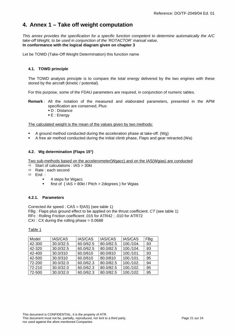
Reference: DO/TF-2049/04 Ed. 01
This document is CONFIDENTIAL, it is the property of ATR.This document must not be, partially, reproduced, nor lent to a third party, Page 21 sur 24nor used against the afore mentioned Companies
4. Annex 1 – Take off weight computation
This annex provides the specification for a specific function competent to determine automatically the A/Ctake-off Weight, to be used in conjunction of the ‘ROTACTOR’ manual value,In conformance with the logical diagram given on chapter 3
Let be TOWD (Take-Off Weight Determination) this function name
4.1. TOWD principle
The TOWD analysis principle is to compare the total energy delivered by the two engines with thesestored by the aircraft (kinetic / potential).
For this purpose, some of the FDAU parameters are required, in conjunction of numeric tables.
Remark : All the notation of the measured and elaborated parameters, presented in the APMspecification are conserved, Plus:§ D : Distance§ E : Energy
The calculated weight is the mean of the values given by two methods:
§ A ground method conducted during the acceleration phase at take-off. (Wg)§ A free air method conducted during the initial climb phase, Flaps and gear retracted.(Wa)
4.2. Wg determination (Flaps 15°)
Two sub-methods based on the accelerometer(Wgacc) and on the IAS(Wgias) are conductedð Start of calculations : IAS > 30ktð Rate : each secondð End :
§ 4 steps for Wgacc§ first of { IAS > 80kt / Pitch > 2degrees } for Wgias
4.2.1. Parameters
Corrected Air speed : CAS = f(IAS) (see table 1)FBg : Flaps plus ground effect to be applied on the thrust coefficient: CT (see table 1)RFc : Rolling Friction coefficient .015 for ATR42 ; .010 for ATR72CXr : CX during the rolling phase = 0.0688
Table 1
Model IAS/CAS IAS/CAS IAS/CAS IAS/CAS FBg42-300 30.0/32.5 60.0/62.5 80.0/82.5 100./104. .9342-320 30.0/32.5 60.0/62.5 80.0/82.5 100./104. .9342-400 30.0/310 60.0/610 80.0/810 100./101. .9342-500 30.0/310 60.0/610 80.0/810 100./101. .9572-200 30.0/32.0 60.0/62.3 80.0/82.5 100./102. .9472-210 30.0/32.0 60.0/62.3 80.0/82.5 100./102. .9572-500 30.0/32.0 60.0/62.3 80.0/82.5 100./102. .95
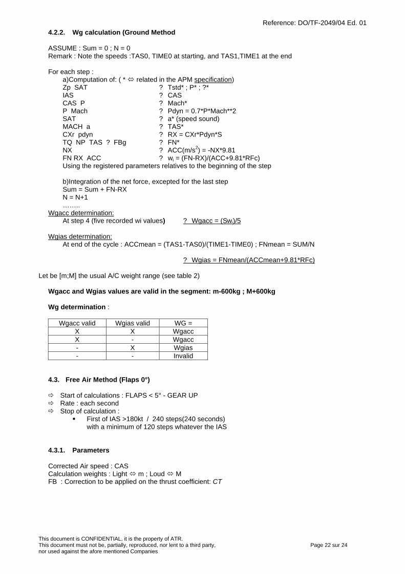
Reference: DO/TF-2049/04 Ed. 01
This document is CONFIDENTIAL, it is the property of ATR.This document must not be, partially, reproduced, nor lent to a third party, Page 22 sur 24nor used against the afore mentioned Companies
4.2.2. Wg calculation (Ground Method
ASSUME : Sum = 0 ; N = 0Remark : Note the speeds :TAS0, TIME0 at starting, and TAS1,TIME1 at the end
For each step :a)Computation of: ( * ó related in the APM specification)Zp SAT ? Tstd* ; P* ; ?*IAS ? CASCAS P ? Mach*P Mach ? Pdyn = 0.7*P*Mach**2SAT ? a* (speed sound)MACH a ? TAS*CXr pdyn ? RX = CXr*Pdyn*STQ NP TAS ? FBg ? FN*NX ? ACC(m/s2) = -NX*9.81FN RX ACC ? wi = (FN-RX)/(ACC+9.81*RFc)Using the registered parameters relatives to the beginning of the step
b)Integration of the net force, excepted for the last stepSum = Sum + FN-RXN = N+1……..
Wgacc determination:At step 4 (five recorded wi values) ? Wgacc = (Swi)/5
Wgias determination:At end of the cycle : ACCmean = (TAS1-TAS0)/(TIME1-TIME0) ; FNmean = SUM/N
? Wgias = FNmean/(ACCmean+9.81*RFc)
Let be [m;M] the usual A/C weight range (see table 2)
Wgacc and Wgias values are valid in the segment: m-600kg ; M+600kg
Wg determination :
Wgacc valid Wgias valid WG =X X WgaccX - Wgacc- X Wgias- - Invalid
4.3. Free Air Method (Flaps 0°)
ð Start of calculations : FLAPS < 5° - GEAR UPð Rate : each secondð Stop of calculation :
§ First of IAS >180kt / 240 steps(240 seconds)with a minimum of 120 steps whatever the IAS
4.3.1. Parameters
Corrected Air speed : CASCalculation weights : Light ó m ; Loud ó MFB : Correction to be applied on the thrust coefficient: CT
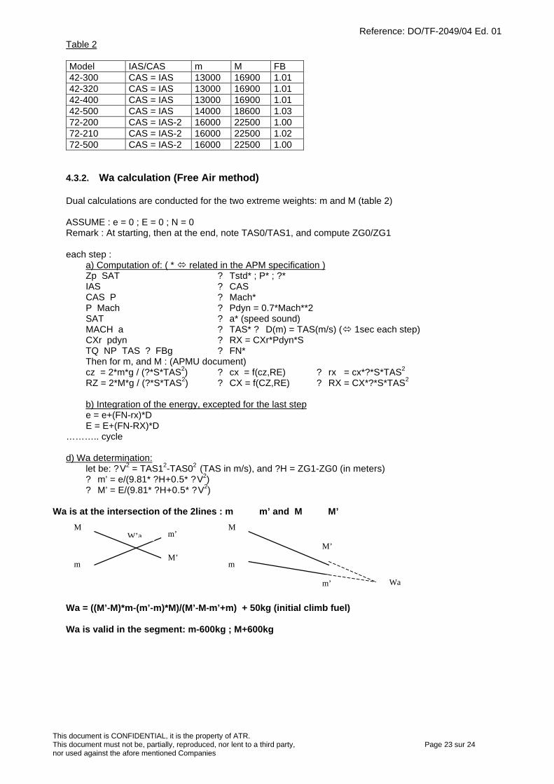
Reference: DO/TF-2049/04 Ed. 01
This document is CONFIDENTIAL, it is the property of ATR.This document must not be, partially, reproduced, nor lent to a third party, Page 23 sur 24nor used against the afore mentioned Companies
Table 2
Model IAS/CAS m M FB42-300 CAS = IAS 13000 16900 1.0142-320 CAS = IAS 13000 16900 1.0142-400 CAS = IAS 13000 16900 1.0142-500 CAS = IAS 14000 18600 1.0372-200 CAS = IAS-2 16000 22500 1.0072-210 CAS = IAS-2 16000 22500 1.0272-500 CAS = IAS-2 16000 22500 1.00
4.3.2. Wa calculation (Free Air method)
Dual calculations are conducted for the two extreme weights: m and M (table 2)
ASSUME : e = 0 ; E = 0 ; N = 0Remark : At starting, then at the end, note TAS0/TAS1, and compute ZG0/ZG1
each step :a) Computation of: ( * ó related in the APM specification )Zp SAT ? Tstd* ; P* ; ?*IAS ? CASCAS P ? Mach*P Mach ? Pdyn = 0.7*Mach**2SAT ? a* (speed sound)MACH a ? TAS* ? D(m) = TAS(m/s) (ó 1sec each step)CXr pdyn ? RX = CXr*Pdyn*STQ NP TAS ? FBg ? FN*Then for m, and M : (APMU document)cz = 2*m*g / (?*S*TAS2) ? cx = f(cz,RE) ? rx = cx*?*S*TAS2
RZ = 2*M*g / (?*S*TAS2) ? CX = f(CZ,RE) ? RX = CX*?*S*TAS2
b) Integration of the energy, excepted for the last stepe = e+(FN-rx)*DE = E+(FN-RX)*D
……….. cycle
d) Wa determination: let be: ?V2 = TAS12-TAS02 (TAS in m/s), and ?H = ZG1-ZG0 (in meters)
? m’ = e/(9.81* ?H+0.5* ?V2)? M’ = E/(9.81* ?H+0.5* ?V2)
Wa is at the intersection of the 2lines : m m’ and M M’
Wa = ((M’-M)*m-(m’-m)*M)/(M’-M-m’+m) + 50kg (initial climb fuel)
Wa is valid in the segment: m-600kg ; M+600kg
M’
M
m
m’W’aM
m
m’
M’
Wa
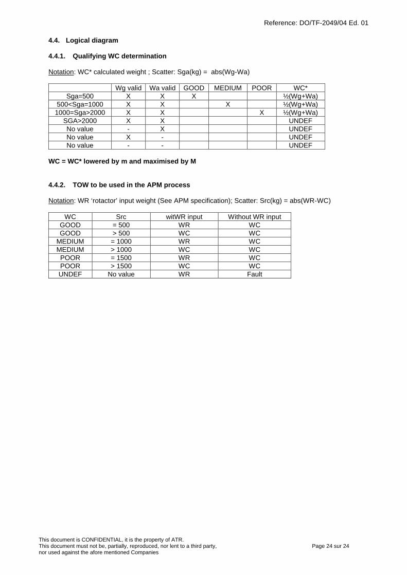
Reference: DO/TF-2049/04 Ed. 01
This document is CONFIDENTIAL, it is the property of ATR.This document must not be, partially, reproduced, nor lent to a third party, Page 24 sur 24nor used against the afore mentioned Companies
4.4. Logical diagram
4.4.1. Qualifying WC determination
Notation: WC* calculated weight ; Scatter: Sga(kg) = abs(Wg-Wa)
Wg valid Wa valid GOOD MEDIUM POOR WC*Sga=500 X X X ½(Wg+Wa)
500<Sga=1000 X X X ½(Wg+Wa)1000=Sga>2000 X X X ½(Wg+Wa)
SGA>2000 X X UNDEFNo value - X UNDEFNo value X - UNDEFNo value - - UNDEF
WC = WC* lowered by m and maximised by M
4.4.2. TOW to be used in the APM process
Notation: WR ‘rotactor’ input weight (See APM specification); Scatter: Src(kg) = abs(WR-WC)
WC Src witWR input Without WR inputGOOD = 500 WR WCGOOD > 500 WC WC
MEDIUM = 1000 WR WCMEDIUM > 1000 WC WCPOOR = 1500 WR WCPOOR > 1500 WC WCUNDEF No value WR Fault
Page 1 sur 5
ENHANCED SURVEILLANCE & ADS-B
SPECIFICATION
REFERENCE DO/TY 3166/04 Ed.01
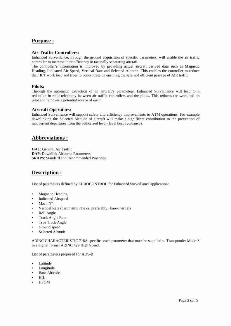
Page 2 sur 5
Purpose :
Air Traffic Controllers:Enhanced Surveillance, through the ground acquisition of specific parameters, will enable the air trafficcontroller to increase their efficiency in tactically separating aircraft.The controller’s information is improved by providing actual aircraft derived data such as MagneticHeading, Indicated Air Speed, Vertical Rate and Selected Altitude. This enables the controller to reducetheir R/T work load and frees to concentrate on ensuring the safe and efficient passage of AIR traffic.
Pilots:Through the automatic extraction of an aircraft’s parameters, Enhanced Surveillance will lead to areduction in ratio telephony between air traffic controllers and the pilots. This reduces the workload onpilot and removes a potential source of error.
Aircraft Operators:Enhanced Surveillance will support safety and efficiency improvements to ATM operations. For exampledownlinking the Selected Altitude of aircraft will make a significant contribution to the prevention ofinadvertent departures from the authorized level (level bust avoidance).
Abbreviations :
GAT: General Air TrafficDAP: Downlink Airborne ParametersSRAPS: Standard and Recommended Practices
Description :
List of parameters defined by EUROCONTROL for Enhanced Surveillance application:
• Magnetic Heading • Indicated Airspeed• Mach N°• Vertical Rate (barometric rate or, preferably , baro-inertial)• Roll Angle• Track Angle Rate• True Track Angle• Ground speed• Selected Altitude
ARINC CHARACTERISTIC 718A specifies each parameter that must be supplied to Transponder Mode-Sin a digital format ARINC 429 High Speed.
List of parameters proposed for ADS-B
• Latitude• Longitude• Baro Altitude• HIL• HFOM
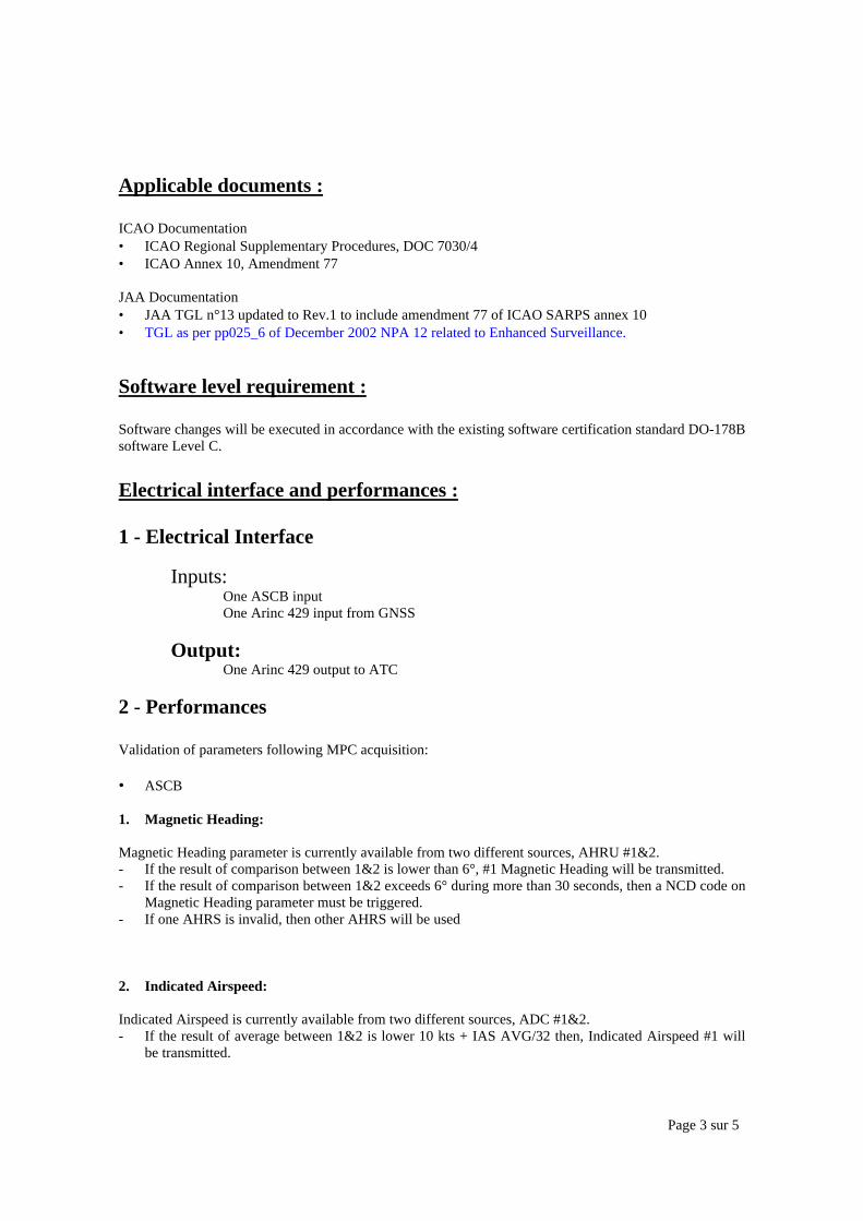
Page 3 sur 5
Applicable documents :
ICAO Documentation• ICAO Regional Supplementary Procedures, DOC 7030/4• ICAO Annex 10, Amendment 77
JAA Documentation• JAA TGL n°13 updated to Rev.1 to include amendment 77 of ICAO SARPS annex 10• TGL as per pp025_6 of December 2002 NPA 12 related to Enhanced Surveillance.
Software level requirement :
Software changes will be executed in accordance with the existing software certification standard DO-178Bsoftware Level C.
Electrical interface and performances :
1 - Electrical Interface
Inputs:One ASCB inputOne Arinc 429 input from GNSS
Output:One Arinc 429 output to ATC
2 - Performances
Validation of parameters following MPC acquisition:
• ASCB
1. Magnetic Heading:
Magnetic Heading parameter is currently available from two different sources, AHRU #1&2.- If the result of comparison between 1&2 is lower than 6°, #1 Magnetic Heading will be transmitted.- If the result of comparison between 1&2 exceeds 6° during more than 30 seconds, then a NCD code on
Magnetic Heading parameter must be triggered.- If one AHRS is invalid, then other AHRS will be used
2. Indicated Airspeed:
Indicated Airspeed is currently available from two different sources, ADC #1&2.- If the result of average between 1&2 is lower 10 kts + IAS AVG/32 then, Indicated Airspeed #1 will
be transmitted.

Page 4 sur 5
- If the result of average between 1&2 exceeds 10 kts + IAS AVG/32 during more than 30 seconds, thena NCD code on Indicated Airspeed parameter must be triggered.
- If one ADC is invalid, then other ADC will be used
• ARINC 429
All parameters taken from HT1000 General Purpose Output Bus N°3, will be automatically transmittedtowards MPC output, excepted Track Angle Rate * parameter that will need to be internally derived fromTrue Track Angle and then output.
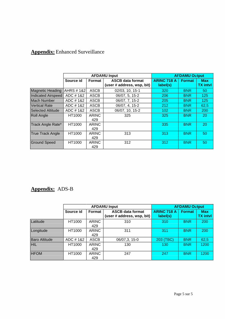
Page 5 sur 5
Appendix: Enhanced Surveillance
AFDAMU Input AFDAMU Output Source id Format ASCB data format
(user # address, wsp, bit)ARINC 718 A
label(s)Format Max
TX intvlMagnetic Heading AHRS # 1&2 ASCB 02/03, 10, 15-1 320 BNR 50Indicated Airspeed ADC # 1&2 ASCB 06/07, 5, 15-2 206 BNR 125Mach Number ADC # 1&2 ASCB 06/07, 7, 15-2 205 BNR 125Vertical Rate ADC # 1&2 ASCB 06/07, 4, 15-2 212 BNR 62,5Selected Altitude ADC # 1&2 ASCB 06/07, 10, 15-2 102 BNR 200Roll Angle HT1000 ARINC
429325 325 BNR 20
Track Angle Rate* HT1000 ARINC429
335 BNR 20
True Track Angle HT1000 ARINC429
313 313 BNR 50
Ground Speed HT1000 ARINC429
312 312 BNR 50
Appendix: ADS-B
AFDAMU Input AFDAMU Output Source id Format ASCB data format
(user # address, wsp, bit)ARINC 718 A
label(s)Format Max
TX intvlLatitude HT1000 ARINC
429310 310 BNR 200
Longitude HT1000 ARINC429
311 311 BNR 200
Baro Altitude ADC # 1&2 ASCB 06/07,3, 15-0 203 (TBC) BNR 62,5HIL HT1000 ARINC
429130 130 BNR 1200
HFOM HT1000 ARINC429
247 247 BNR 1200
Page 1 sur 11
AFCS TROUBLESHOOTING FUNCTION
SPECIFICATION
REFERENCE DO/TY 3167/04 Ed.01
Page 2 sur 11
PurposeThis annex describes the AFCS troubleshooting function to implement in APMU.
AbbreviationsADC Air Data ComputerADU Advisory Display UnitAFCS Automatic Flight Control SystemASCB Avionics Standard Communication BusBITE Built-In TestFFS Flight Fault SumaryGMT Ground Maintenance TestT/S Troubleshooting
DescriptionGeneral:The aim of this function is to help troubleshooting ATR AFCS. It will guide the operator in identifying thereason of the failure. Moreover, it will perform an automatic decoding of FFS.
Principle:This function try to reproduce the T/S approach which is done by a specialist for solving an AFCS trouble.Questions are asked to the operator ; these questions have several possible answers. Depending of operator’schoice, other questions are asked to complete the T/S and suggest the most probable cause.
From MCDU, several menus will be proposed for troubleshooting AFCS:1. a general troubleshooting procedure,2. troubleshooting from ADU messages,3. use of ground maintenance test (GMT) messages,4. decoding of FLIGHT FAULT SUMMARY data ; decoding can be done automatically when FFS message is
displayed on ADU or manually (pilot enters FFS codes)
The program uses files containing the steps/answers and the various decision points.
From an operational point of view:• description text is displayed on MCDU page 1 ; some description may exceed one MCDU page, operator
must use NEXT/PREVIOUS keys to display all pages (example in Description N° 15)• pages indicating relevant choices are displayed after description pages ; page selection will be done via
NEXT/PREVIOUS keys ; the lateral selection keys allow choice of answer.
Note:some lines in files are to be chosen depending of aircraft (example: Description N° 3)
The T/S data are described in 3 files provided in electronic format (tables DESCRIPTION, CHOICE and FFS infile “AFCS tables.xls”) – see sample in appendix :• file DESCRIPTION containing the steps (instructions/comments) for the operator ; its format is:
- an identification number of text to be displayed – this number is the entry point in the table ; first entrypoint id. is:• 101 for general troubleshooting procedure,• 1 for troubleshooting from ADU messages,• 50 for use of GMT,• 202 (for ATR42-300) or 203 (other models) for decoding of FFS,
- the text to be displayed,• file CHOICE listing a number of possible answers (choices) to be selected by the operator ; its format is:
- column A: an identification number of the call (number of the step where the question is asked),
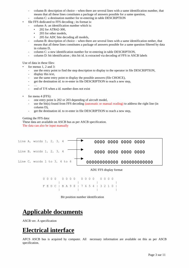
Page 3 sur 11
- column B: description of choice – when there are several lines with a same identification number, thatmeans that all these lines constitutes a package of answers possible for a same question,
- column C: a destination number for re-entering in table DESCRIPTION• file FFS dedicated to FFS decoding ; its format is:
- column A: an identification number which is:• 202 for ATR42-300,• 203 for other models,• 205 for ADC bite decoding all models,
- column B: description of choice – when there are several lines with a same identification nmber, thatmeans that all these lines constitutes a package of answers possible for a same question filtered by datain column D,
- column C: a new identification number for re-entering in table DESCRIPTION,- column D: bit identification ; this bit id. is extracted via decoding of FFS in ASCB labels
Use of data in these files:• for menus 1, 2 and 3:
- use the entry point to find the step description to display to the operator in file DESCRIPTION,- display this text,- use the same entry point to display the possible answers (file CHOICE),- get the destination id. to re-enter in file DESCRIPTION to reach a new step,- …- end of T/S when a id. number does not exist
• for menu 4 (FFS):- one entry point is 202 or 203 depending of aircraft model,- use the bit(s) found from FFS decoding (automatic or manual reading) to address the right line (in
column D),- get the destination id. to re-enter in file DESCRIPTION to reach a new step,
Getting the FFS data:These data are available on ASCB bus as per ASCB specification.The data can also be input manually
Applicable documentsASCB ver. A specification
Electrical interfaceAFCS ASCB bus is acquired by computer. All necessary information are available on this as per ASCBspecification.
0000 0000 0000 0000
0000 0000 0000 0000
000000000000 000000000000
Line A, words 1, 2, 3, 4
Line B, words 1, 2, 3, 4
Line C, words 1 to 3, 4 to 6
ADU FFS display format
0 0 0 0 0 0 0 0 0 0 0 0 0 0 0 0 | | | |F E D C | B A 9 8 | 7 6 5 4 | 3 2 1 0 | | | | |
Bit position number identification

Page 4 sur 11
Software level requirementDO178 level D
Performances

Page 5 sur 11
Appendix
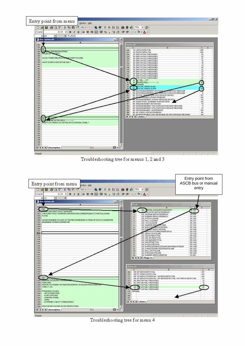
Page 6 sur 11
Entry point fromASCB bus or manual
entry
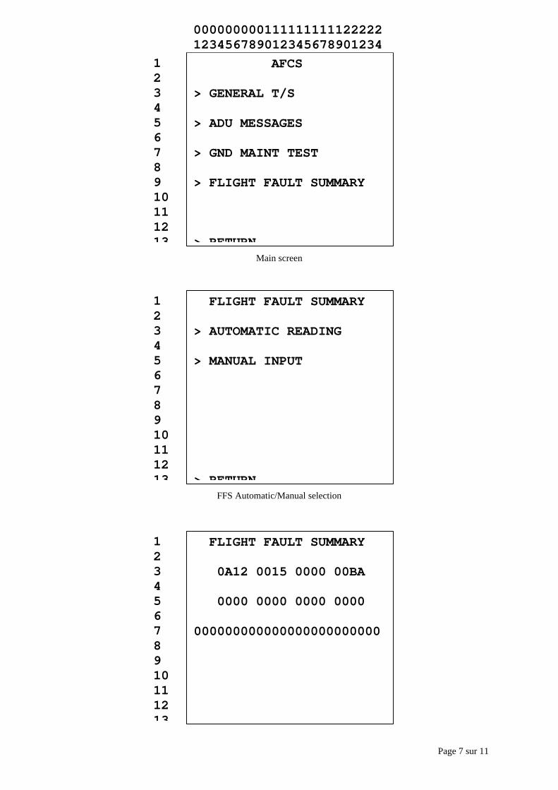
Page 7 sur 11
Main screen
FFS Automatic/Manual selection
AFCS
> GENERAL T/S
> ADU MESSAGES
> GND MAINT TEST
> FLIGHT FAULT SUMMARY
> RETURN
12345678910111213
000000000111111111122222123456789012345678901234
FLIGHT FAULT SUMMARY
> AUTOMATIC READING
> MANUAL INPUT
> RETURN
12345678910111213
FLIGHT FAULT SUMMARY
0A12 0015 0000 00BA
0000 0000 0000 0000
000000000000000000000000
12345678910111213

Page 8 sur 11
FFS manual entry
Example of screens
FIRST MSG AT DISC 1/2
>YD DSNGD YD DSNGD FL<
>AP DSNGD AP DSNGD FL<
>AP/YD DIS AD/YD DIS FL<
>CPL DAT INV ADV FAULT<
>DIS ANNUN DATA FAULT
> RETURN
12345678910111213
000000000111111111122222123456789012345678901234
FIRST MSG AT DISC 2/2
>ENGAGE INHIBIT
>PITCH TRIM FAIL
>PITCH MISTRIM
>RETRIM ROLL AIL MISTRIM
>UNKNOWN
> RETURN
12345678910111213
000000000111111111122222123456789012345678901234
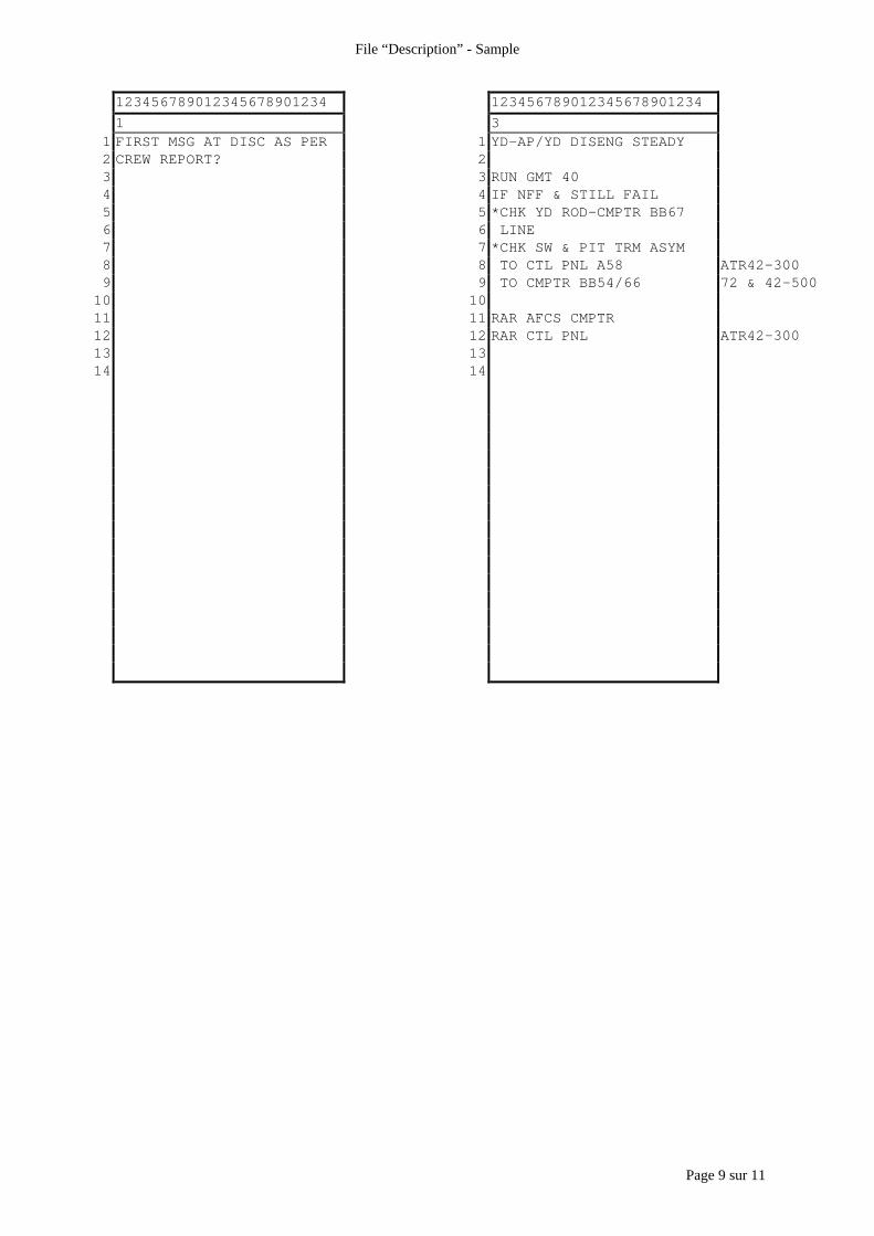
Page 9 sur 11
File “Description” - Sample
123456789012345678901234 1234567890123456789012341 3
1 FIRST MSG AT DISC AS PER 1 YD-AP/YD DISENG STEADY2 CREW REPORT? 23 3 RUN GMT 404 4 IF NFF & STILL FAIL5 5 *CHK YD ROD-CMPTR BB676 6 LINE7 7 *CHK SW & PIT TRM ASYM8 8 TO CTL PNL A58 ATR42-3009 9 TO CMPTR BB54/66 72 & 42-500
10 1011 11 RAR AFCS CMPTR12 12 RAR CTL PNL ATR42-30013 1314 14
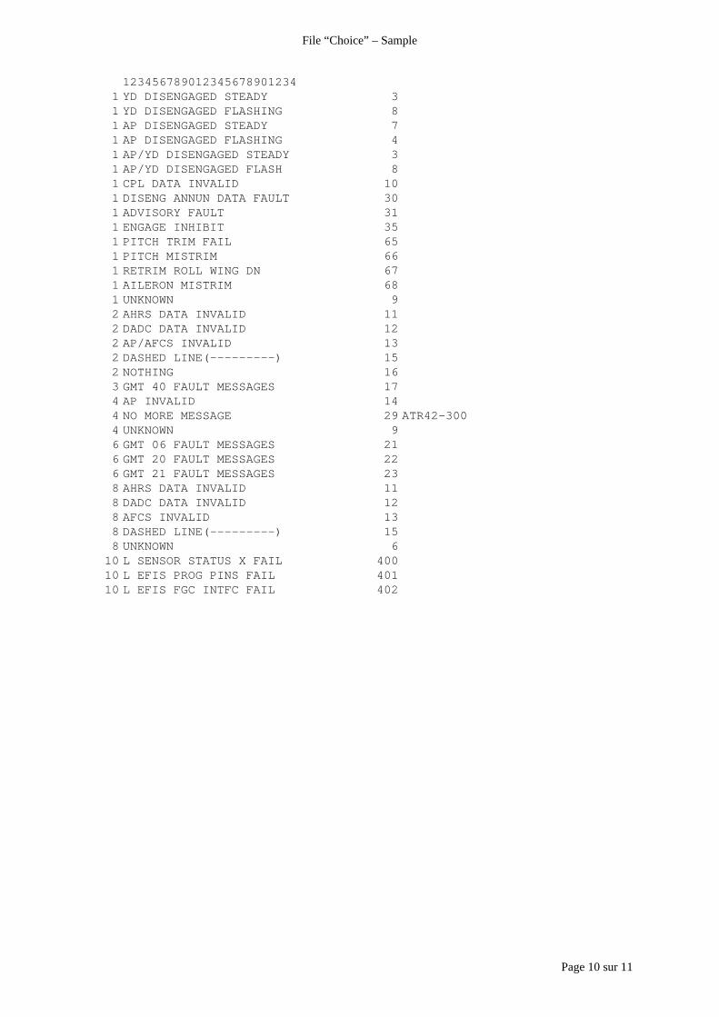
Page 10 sur 11
File “Choice” – Sample
1234567890123456789012341 YD DISENGAGED STEADY 31 YD DISENGAGED FLASHING 81 AP DISENGAGED STEADY 71 AP DISENGAGED FLASHING 41 AP/YD DISENGAGED STEADY 31 AP/YD DISENGAGED FLASH 81 CPL DATA INVALID 101 DISENG ANNUN DATA FAULT 301 ADVISORY FAULT 311 ENGAGE INHIBIT 351 PITCH TRIM FAIL 651 PITCH MISTRIM 661 RETRIM ROLL WING DN 671 AILERON MISTRIM 681 UNKNOWN 92 AHRS DATA INVALID 112 DADC DATA INVALID 122 AP/AFCS INVALID 132 DASHED LINE(---------) 152 NOTHING 163 GMT 40 FAULT MESSAGES 174 AP INVALID 144 NO MORE MESSAGE 29 ATR42-3004 UNKNOWN 96 GMT 06 FAULT MESSAGES 216 GMT 20 FAULT MESSAGES 226 GMT 21 FAULT MESSAGES 238 AHRS DATA INVALID 118 DADC DATA INVALID 128 AFCS INVALID 138 DASHED LINE(---------) 158 UNKNOWN 6
10 L SENSOR STATUS X FAIL 40010 L EFIS PROG PINS FAIL 40110 L EFIS FGC INTFC FAIL 402
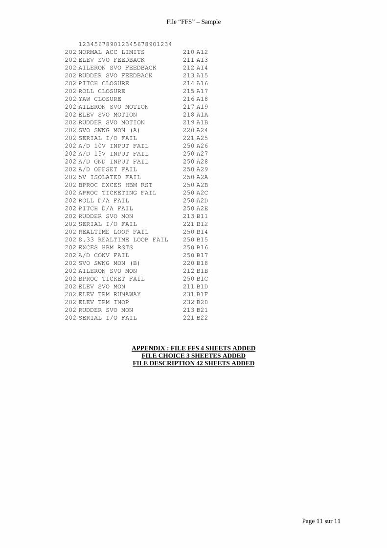
Page 11 sur 11
File “FFS” – Sample
123456789012345678901234202 NORMAL ACC LIMITS 210 A12202 ELEV SVO FEEDBACK 211 A13202 AILERON SVO FEEDBACK 212 A14202 RUDDER SVO FEEDBACK 213 A15202 PITCH CLOSURE 214 A16202 ROLL CLOSURE 215 A17202 YAW CLOSURE 216 A18202 AILERON SVO MOTION 217 A19202 ELEV SVO MOTION 218 A1A202 RUDDER SVO MOTION 219 A1B202 SVO SWNG MON (A) 220 A24202 SERIAL I/O FAIL 221 A25202 A/D 10V INPUT FAIL 250 A26202 A/D 15V INPUT FAIL 250 A27202 A/D GND INPUT FAIL 250 A28202 A/D OFFSET FAIL 250 A29202 5V ISOLATED FAIL 250 A2A202 BPROC EXCES HBM RST 250 A2B202 APROC TICKETING FAIL 250 A2C202 ROLL D/A FAIL 250 A2D202 PITCH D/A FAIL 250 A2E202 RUDDER SVO MON 213 B11202 SERIAL I/O FAIL 221 B12202 REALTIME LOOP FAIL 250 B14202 8.33 REALTIME LOOP FAIL 250 B15202 EXCES HBM RSTS 250 B16202 A/D CONV FAIL 250 B17202 SVO SWNG MON (B) 220 B18202 AILERON SVO MON 212 B1B202 BPROC TICKET FAIL 250 B1C202 ELEV SVO MON 211 B1D202 ELEV TRM RUNAWAY 231 B1F202 ELEV TRM INOP 232 B20202 RUDDER SVO MON 213 B21202 SERIAL I/O FAIL 221 B22
APPENDIX : FILE FFS 4 SHEETS ADDEDFILE CHOICE 3 SHEETES ADDED
FILE DESCRIPTION 42 SHEETS ADDED
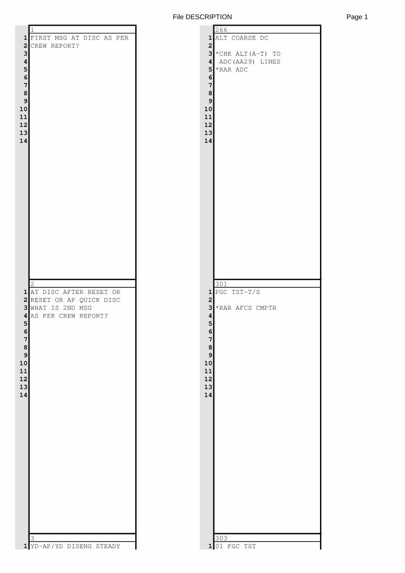
File DESCRIPTION Page 1
1 2661 FIRST MSG AT DISC AS PER 1 ALT COARSE DC2 CREW REPORT? 23 3 *CHK ALT(A-T) TO4 4 ADC(AA29) LINES5 5 *RAR ADC6 67 78 89 9
10 1011 1112 1213 1314 14
2 3011 AT DISC AFTER RESET OR 1 FGC TST-T/S2 RESET OR AP QUICK DISC 23 WHAT IS 2ND MSG 3 *RAR AFCS CMPTR4 AS PER CREW REPORT? 45 56 67 78 89 9
10 1011 1112 1213 1314 14
3 3031 YD-AP/YD DISENG STEADY 1 01 FGC TST
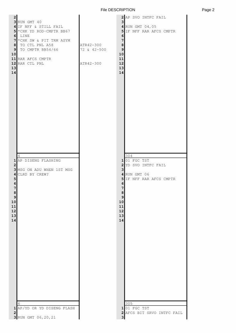
File DESCRIPTION Page 2
2 2 AP SVO INTFC FAIL3 RUN GMT 40 34 IF NFF & STILL FAIL 4 RUN GMT 04,055 *CHK YD ROD-CMPTR BB67 5 IF NFF RAR AFCS CMPTR6 LINE 67 *CHK SW & PIT TRM ASYM 78 TO CTL PNL A58 ATR42-300 89 TO CMPTR BB54/66 72 & 42-500 9
10 1011 RAR AFCS CMPTR 1112 RAR CTL PNL ATR42-300 1213 1314 14
4 3041 AP DISENG FLASHING 1 01 FGC TST2 2 YD SVO INTFC FAIL3 MSG ON ADU WHEN 1ST MSG 34 CLRD BY CREW? 4 RUN GMT 065 5 IF NFF RAR AFCS CMPTR6 67 78 89 9
10 1011 1112 1213 1314 14
6 3051 AP/YD OR YD DISENG FLASH 1 01 FGC TST2 2 AFCS BIT SRVO INTFC FAIL3 RUN GMT 06,20,21 3
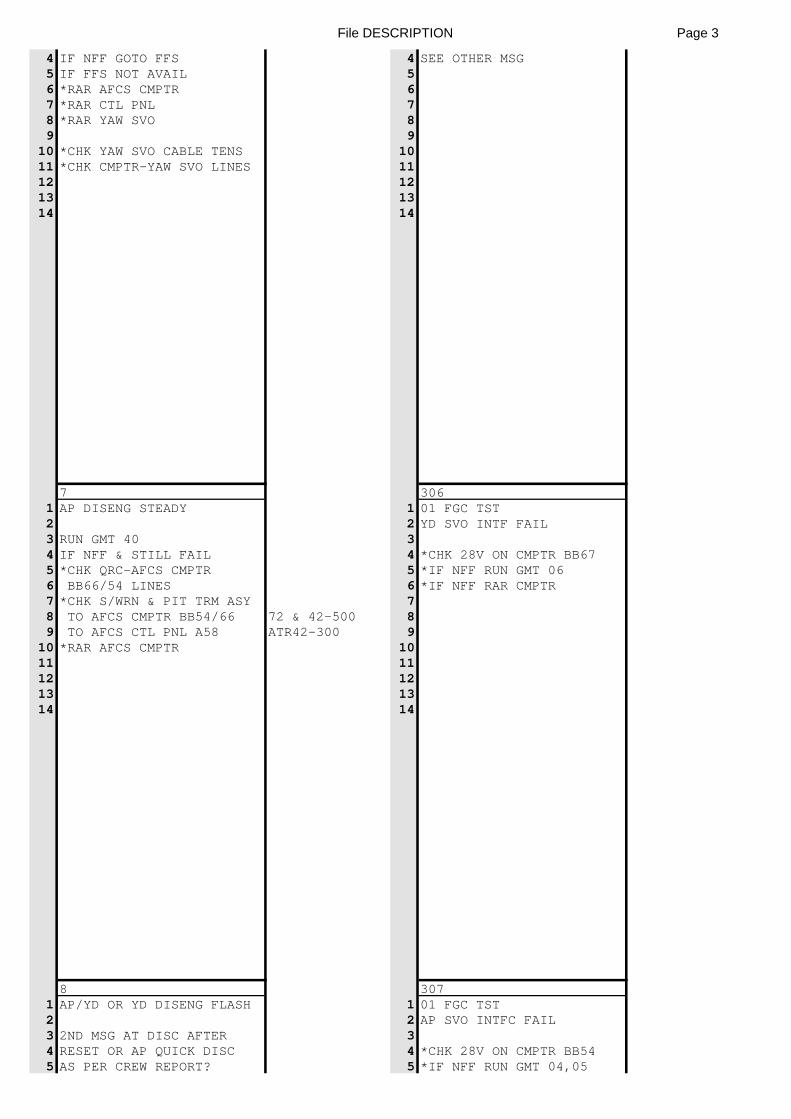
File DESCRIPTION Page 3
4 IF NFF GOTO FFS 4 SEE OTHER MSG5 IF FFS NOT AVAIL 56 *RAR AFCS CMPTR 67 *RAR CTL PNL 78 *RAR YAW SVO 89 9
10 *CHK YAW SVO CABLE TENS 1011 *CHK CMPTR-YAW SVO LINES 1112 1213 1314 14
7 3061 AP DISENG STEADY 1 01 FGC TST2 2 YD SVO INTF FAIL3 RUN GMT 40 34 IF NFF & STILL FAIL 4 *CHK 28V ON CMPTR BB675 *CHK QRC-AFCS CMPTR 5 *IF NFF RUN GMT 066 BB66/54 LINES 6 *IF NFF RAR CMPTR7 *CHK S/WRN & PIT TRM ASY 78 TO AFCS CMPTR BB54/66 72 & 42-500 89 TO AFCS CTL PNL A58 ATR42-300 9
10 *RAR AFCS CMPTR 1011 1112 1213 1314 14
8 3071 AP/YD OR YD DISENG FLASH 1 01 FGC TST2 2 AP SVO INTFC FAIL3 2ND MSG AT DISC AFTER 34 RESET OR AP QUICK DISC 4 *CHK 28V ON CMPTR BB545 AS PER CREW REPORT? 5 *IF NFF RUN GMT 04,05
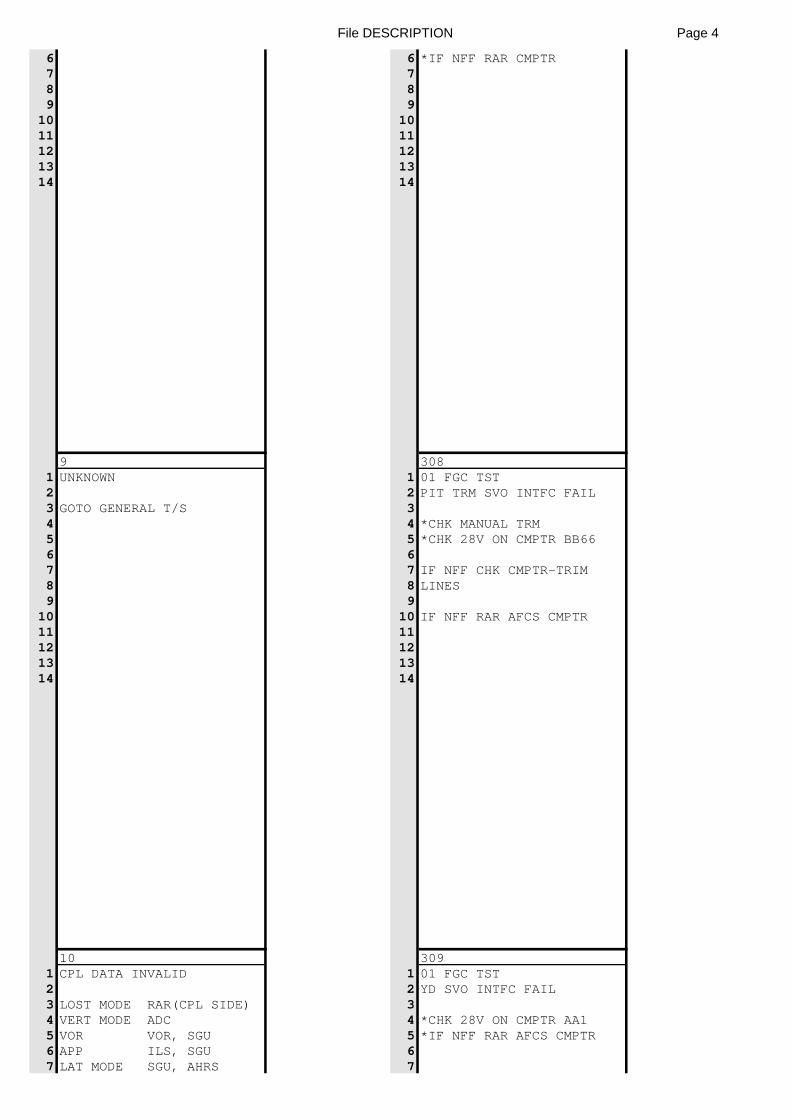
File DESCRIPTION Page 4
6 6 *IF NFF RAR CMPTR7 78 89 9
10 1011 1112 1213 1314 14
9 3081 UNKNOWN 1 01 FGC TST2 2 PIT TRM SVO INTFC FAIL3 GOTO GENERAL T/S 34 4 *CHK MANUAL TRM5 5 *CHK 28V ON CMPTR BB666 67 7 IF NFF CHK CMPTR-TRIM8 8 LINES9 9
10 10 IF NFF RAR AFCS CMPTR11 1112 1213 1314 14
10 3091 CPL DATA INVALID 1 01 FGC TST2 2 YD SVO INTFC FAIL3 LOST MODE RAR(CPL SIDE) 34 VERT MODE ADC 4 *CHK 28V ON CMPTR AA15 VOR VOR, SGU 5 *IF NFF RAR AFCS CMPTR6 APP ILS, SGU 67 LAT MODE SGU, AHRS 7
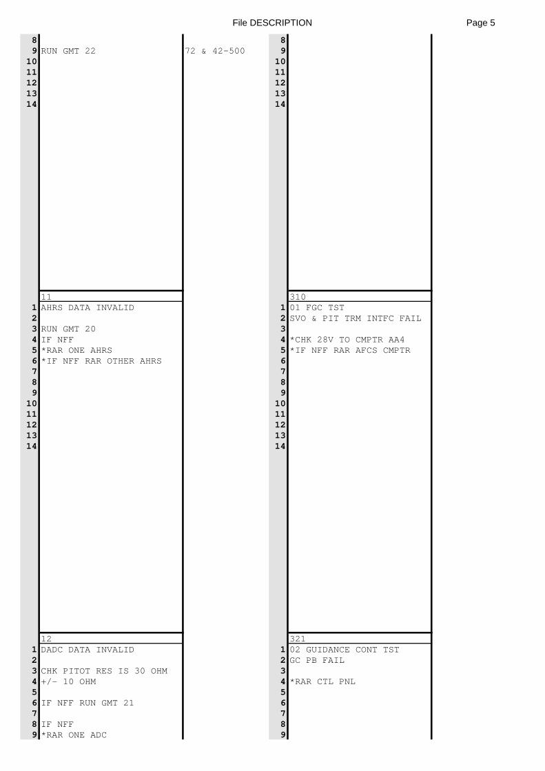
File DESCRIPTION Page 5
8 89 RUN GMT 22 72 & 42-500 9
10 1011 1112 1213 1314 14
11 3101 AHRS DATA INVALID 1 01 FGC TST2 2 SVO & PIT TRM INTFC FAIL3 RUN GMT 20 34 IF NFF 4 *CHK 28V TO CMPTR AA45 *RAR ONE AHRS 5 *IF NFF RAR AFCS CMPTR6 *IF NFF RAR OTHER AHRS 67 78 89 9
10 1011 1112 1213 1314 14
12 3211 DADC DATA INVALID 1 02 GUIDANCE CONT TST2 2 GC PB FAIL3 CHK PITOT RES IS 30 OHM 34 +/- 10 OHM 4 *RAR CTL PNL5 56 IF NFF RUN GMT 21 67 78 IF NFF 89 *RAR ONE ADC 9
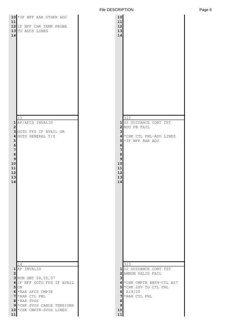
File DESCRIPTION Page 6
10 *IF NFF RAR OTHER ADC 1011 1112 IF NFF CHK TEMP PROBE 1213 TO ADCS LINES 1314 14
13 3221 AP/AFCS INVALID 1 02 GUIDANCE CONT TST2 2 ADU PB FAIL3 GOTO FFS IF AVAIL OR 34 GOTO GENERAL T/S 4 *CHK CTL PNL-ADU LINES5 5 *IF NFF RAR ADU6 67 78 89 9
10 1011 1112 1213 1314 14
14 3231 AP INVALID 1 02 GUIDANCE CONT TST2 2 ANNUN VALID FAIL3 RUN GMT 04,05,07 34 IF NFF GOTO FFS IF AVAIL 4 *CHK CMPTR BB89-CTL A575 OR 5 *CHK 28V TO CTL PNL6 *RAR AFCS CMPTR 6 A19/207 *RAR CTL PNL 7 *RAR CTL PNL8 *RAR SVOS 89 *CHK SVOS CABLE TENSIONS 9
10 *CHK CMPTR-SVOS LINES 1011 11
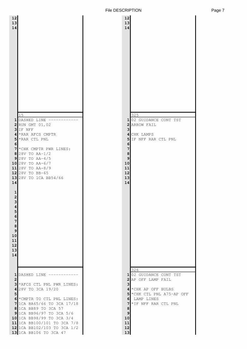
File DESCRIPTION Page 7
12 1213 1314 14
15 3251 DASHED LINE ------------ 1 02 GUIDANCE CONT TST2 RUN GMT 01,02 2 ARROW FAIL3 IF NFF 34 *RAR AFCS CMPTR 4 CHK LAMPS5 *RAR CTL PNL 5 IF NFF RAR CTL PNL6 67 *CHK CMPTR PWR LINES: 78 28V TO AA-1/2 89 28V TO AA-4/5 9
10 28V TO AA-6/7 1011 28V TO AA-8/9 1112 28V TO BB-65 1213 28V TO 1CA BB54/66 1314 14
123456789
1011121314
3261 DASHED LINE ------------ 1 02 GUIDANCE CONT TST2 2 AP OFF LAMP FAIL3 *AFCS CTL PNL PWR LINES: 34 28V TO 3CA 19/20 4 *CHK AP OFF BULBS5 5 *CHK CTL PNL A75-AP OFF6 *CMPTR TO CTL PNL LINES: 6 LAMP LINES7 1CA BA65/66 TO 3CA 17/18 7 *IF NFF RAR CTL PNL8 1CA BB89 TO 3CA 57 89 1CA BB96/97 TO 3CA 5/6 9
10 1CA BB98/99 TO 3CA 3/4 1011 1CA BB100/101 TO 3CA 7/8 1112 1CA BB102/103 TO 3CA 1/2 1213 1CA BB106 TO 3CA 47 13
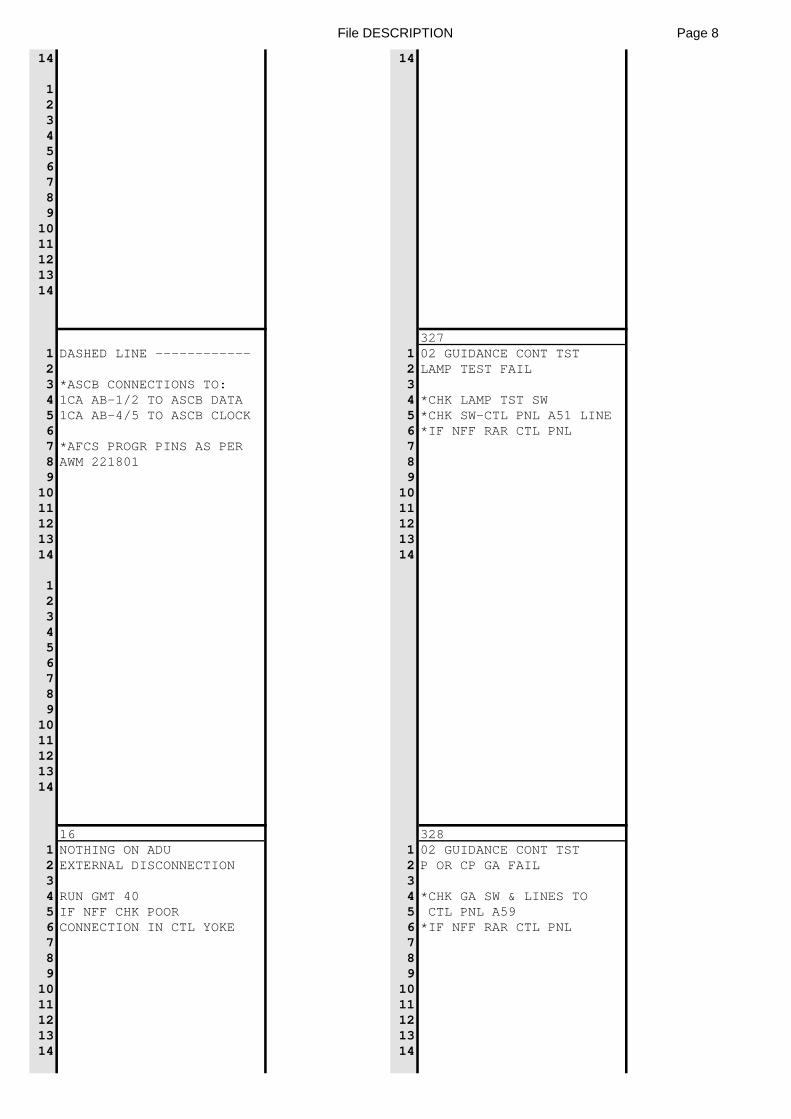
File DESCRIPTION Page 8
14 14
123456789
1011121314
3271 DASHED LINE ------------ 1 02 GUIDANCE CONT TST2 2 LAMP TEST FAIL3 *ASCB CONNECTIONS TO: 34 1CA AB-1/2 TO ASCB DATA 4 *CHK LAMP TST SW5 1CA AB-4/5 TO ASCB CLOCK 5 *CHK SW-CTL PNL A51 LINE6 6 *IF NFF RAR CTL PNL7 *AFCS PROGR PINS AS PER 78 AWM 221801 89 9
10 1011 1112 1213 1314 14
123456789
1011121314
16 3281 NOTHING ON ADU 1 02 GUIDANCE CONT TST2 EXTERNAL DISCONNECTION 2 P OR CP GA FAIL3 34 RUN GMT 40 4 *CHK GA SW & LINES TO5 IF NFF CHK POOR 5 CTL PNL A596 CONNECTION IN CTL YOKE 6 *IF NFF RAR CTL PNL7 78 89 9
10 1011 1112 1213 1314 14
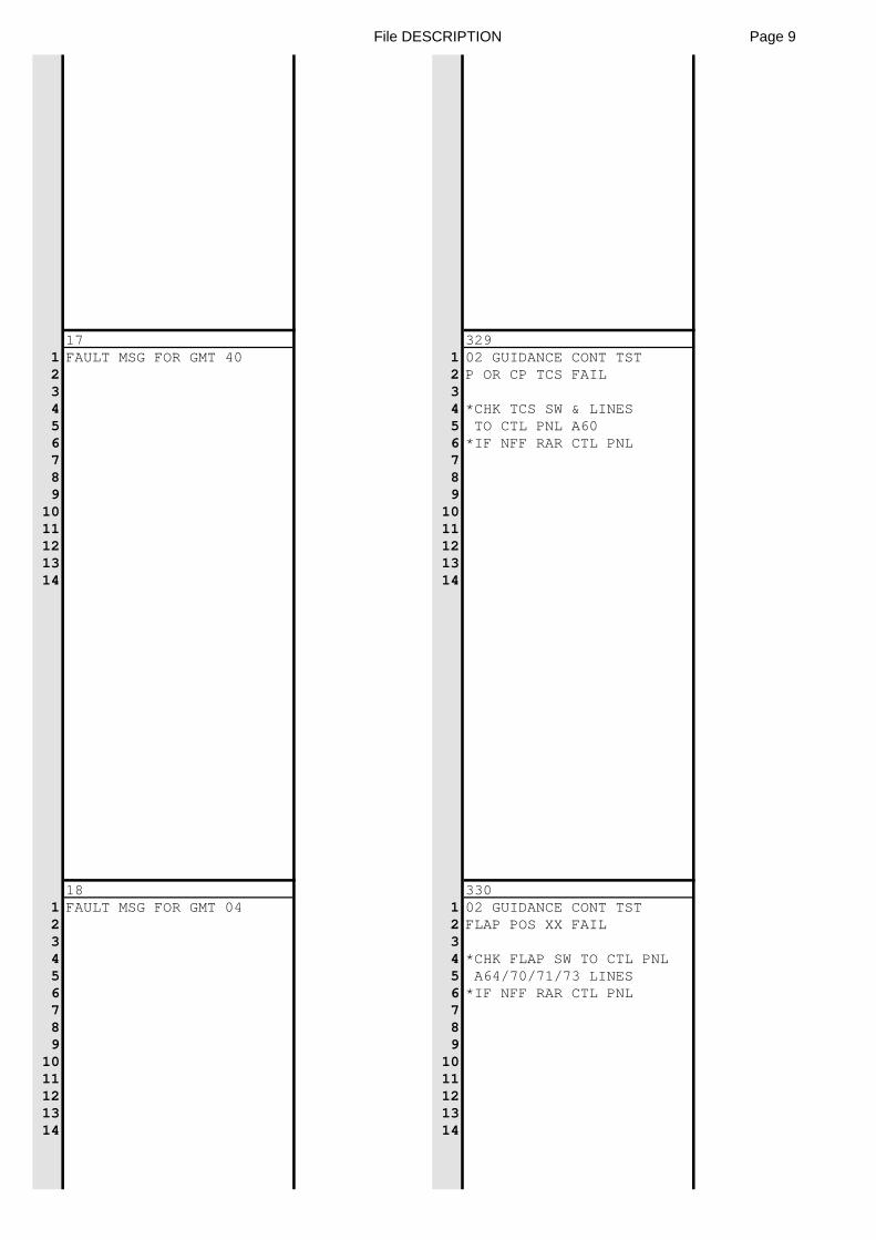
File DESCRIPTION Page 9
17 3291 FAULT MSG FOR GMT 40 1 02 GUIDANCE CONT TST2 2 P OR CP TCS FAIL3 34 4 *CHK TCS SW & LINES5 5 TO CTL PNL A606 6 *IF NFF RAR CTL PNL7 78 89 9
10 1011 1112 1213 1314 14
18 3301 FAULT MSG FOR GMT 04 1 02 GUIDANCE CONT TST2 2 FLAP POS XX FAIL3 34 4 *CHK FLAP SW TO CTL PNL5 5 A64/70/71/73 LINES6 6 *IF NFF RAR CTL PNL7 78 89 9
10 1011 1112 1213 1314 14
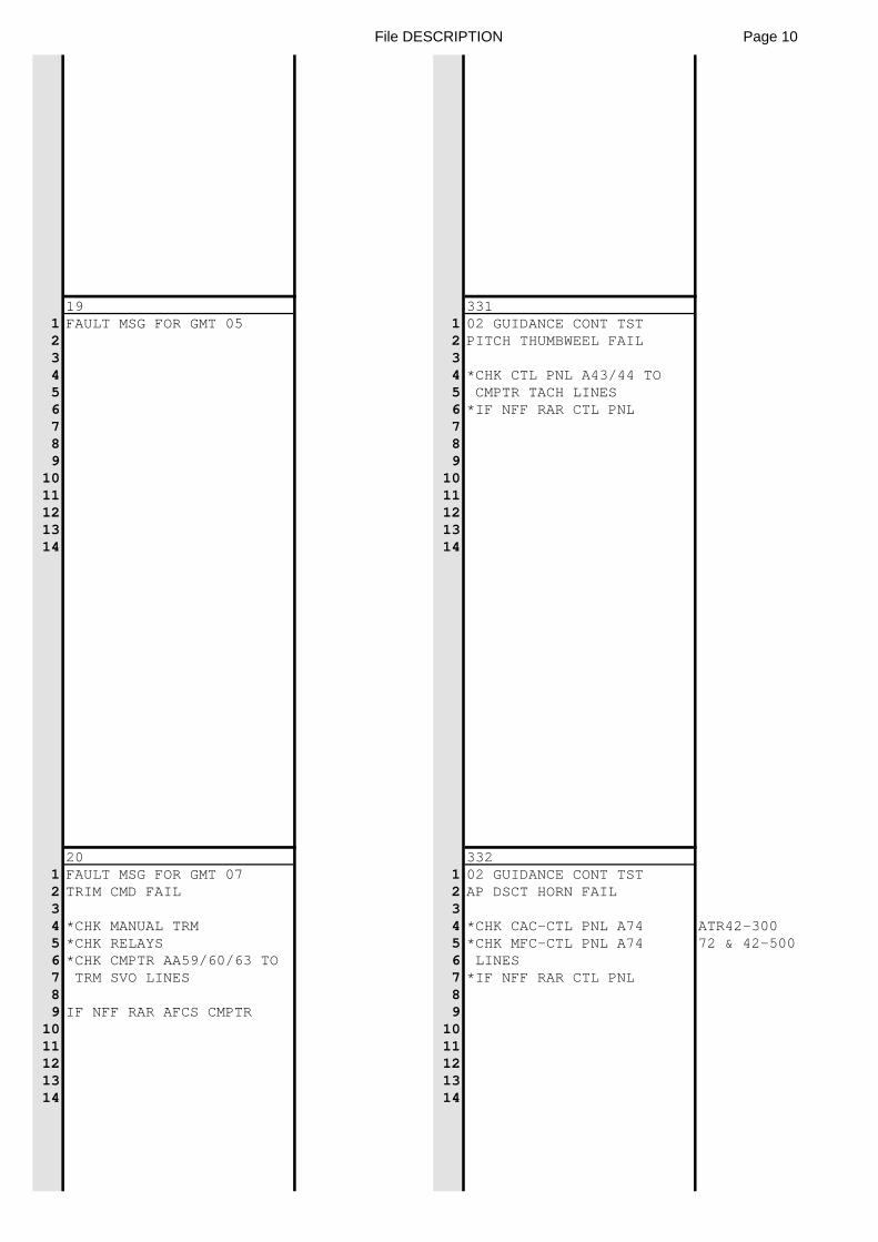
File DESCRIPTION Page 10
19 3311 FAULT MSG FOR GMT 05 1 02 GUIDANCE CONT TST2 2 PITCH THUMBWEEL FAIL3 34 4 *CHK CTL PNL A43/44 TO5 5 CMPTR TACH LINES6 6 *IF NFF RAR CTL PNL7 78 89 9
10 1011 1112 1213 1314 14
20 3321 FAULT MSG FOR GMT 07 1 02 GUIDANCE CONT TST2 TRIM CMD FAIL 2 AP DSCT HORN FAIL3 34 *CHK MANUAL TRM 4 *CHK CAC-CTL PNL A74 ATR42-3005 *CHK RELAYS 5 *CHK MFC-CTL PNL A74 72 & 42-5006 *CHK CMPTR AA59/60/63 TO 6 LINES7 TRM SVO LINES 7 *IF NFF RAR CTL PNL8 89 IF NFF RAR AFCS CMPTR 9
10 1011 1112 1213 1314 14
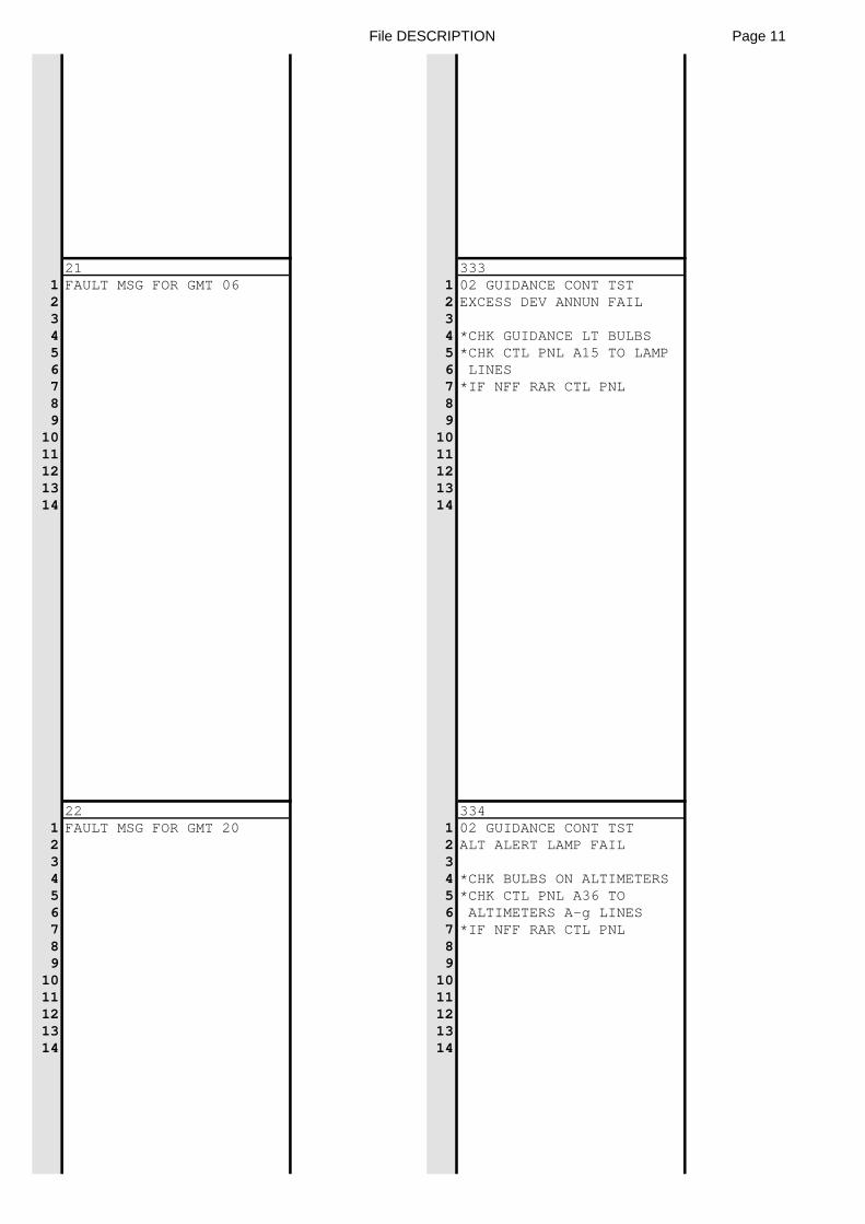
File DESCRIPTION Page 11
21 3331 FAULT MSG FOR GMT 06 1 02 GUIDANCE CONT TST2 2 EXCESS DEV ANNUN FAIL3 34 4 *CHK GUIDANCE LT BULBS5 5 *CHK CTL PNL A15 TO LAMP6 6 LINES7 7 *IF NFF RAR CTL PNL8 89 9
10 1011 1112 1213 1314 14
22 3341 FAULT MSG FOR GMT 20 1 02 GUIDANCE CONT TST2 2 ALT ALERT LAMP FAIL3 34 4 *CHK BULBS ON ALTIMETERS5 5 *CHK CTL PNL A36 TO6 6 ALTIMETERS A-g LINES7 7 *IF NFF RAR CTL PNL8 89 9
10 1011 1112 1213 1314 14
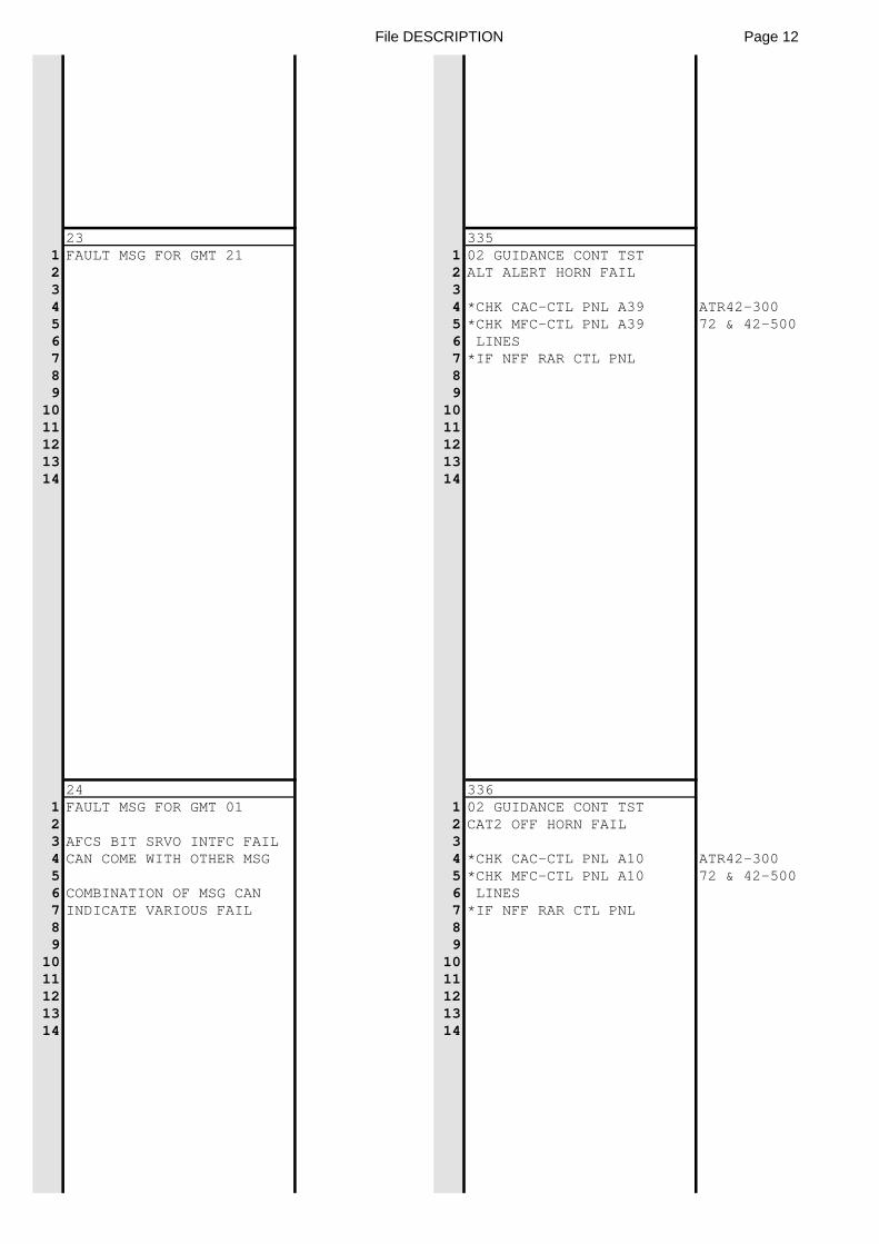
File DESCRIPTION Page 12
23 3351 FAULT MSG FOR GMT 21 1 02 GUIDANCE CONT TST2 2 ALT ALERT HORN FAIL3 34 4 *CHK CAC-CTL PNL A39 ATR42-3005 5 *CHK MFC-CTL PNL A39 72 & 42-5006 6 LINES7 7 *IF NFF RAR CTL PNL8 89 9
10 1011 1112 1213 1314 14
24 3361 FAULT MSG FOR GMT 01 1 02 GUIDANCE CONT TST2 2 CAT2 OFF HORN FAIL3 AFCS BIT SRVO INTFC FAIL 34 CAN COME WITH OTHER MSG 4 *CHK CAC-CTL PNL A10 ATR42-3005 5 *CHK MFC-CTL PNL A10 72 & 42-5006 COMBINATION OF MSG CAN 6 LINES7 INDICATE VARIOUS FAIL 7 *IF NFF RAR CTL PNL8 89 9
10 1011 1112 1213 1314 14
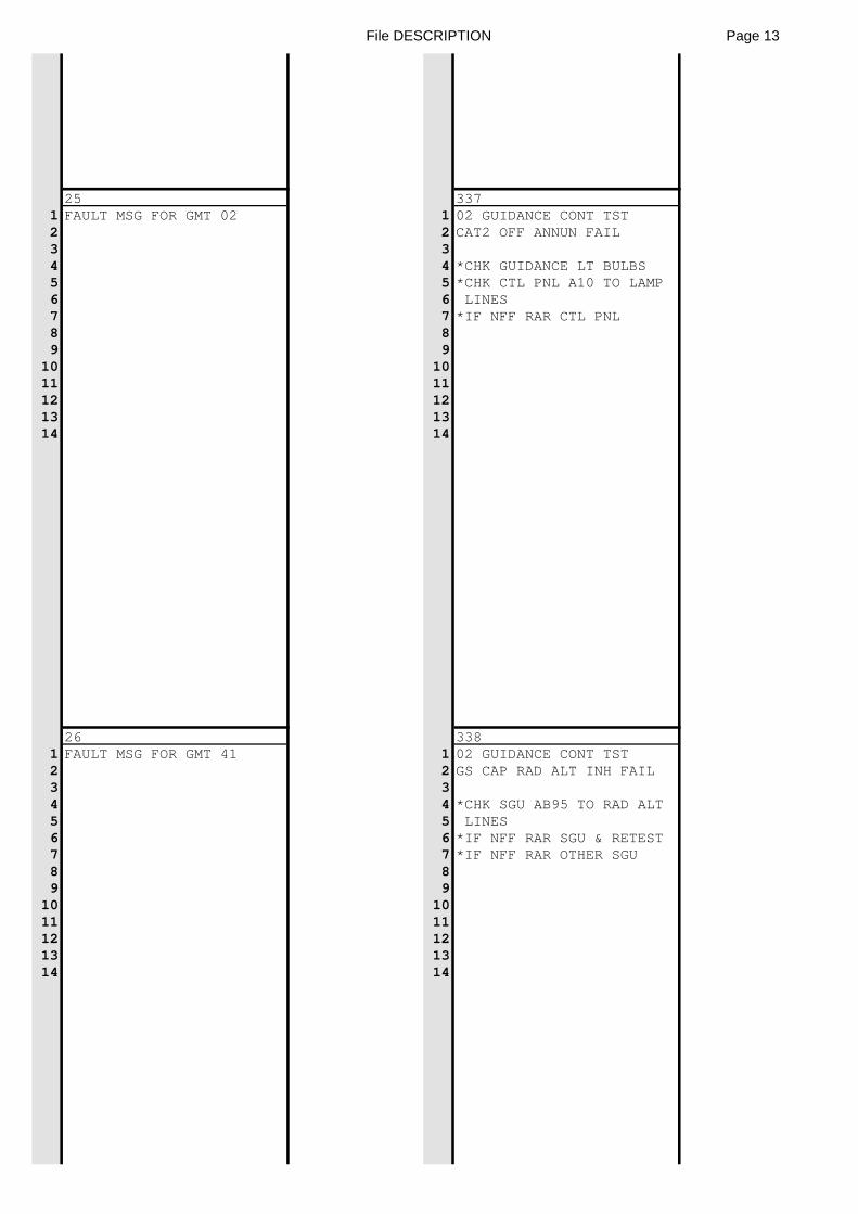
File DESCRIPTION Page 13
25 3371 FAULT MSG FOR GMT 02 1 02 GUIDANCE CONT TST2 2 CAT2 OFF ANNUN FAIL3 34 4 *CHK GUIDANCE LT BULBS5 5 *CHK CTL PNL A10 TO LAMP6 6 LINES7 7 *IF NFF RAR CTL PNL8 89 9
10 1011 1112 1213 1314 14
26 3381 FAULT MSG FOR GMT 41 1 02 GUIDANCE CONT TST2 2 GS CAP RAD ALT INH FAIL3 34 4 *CHK SGU AB95 TO RAD ALT5 5 LINES6 6 *IF NFF RAR SGU & RETEST7 7 *IF NFF RAR OTHER SGU8 89 9
10 1011 1112 1213 1314 14
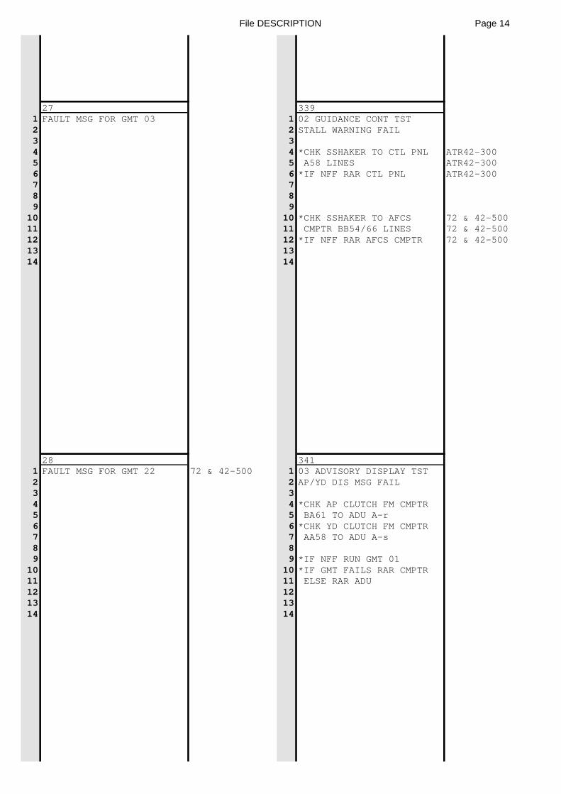
File DESCRIPTION Page 14
27 3391 FAULT MSG FOR GMT 03 1 02 GUIDANCE CONT TST2 2 STALL WARNING FAIL3 34 4 *CHK SSHAKER TO CTL PNL ATR42-3005 5 A58 LINES ATR42-3006 6 *IF NFF RAR CTL PNL ATR42-3007 78 89 9
10 10 *CHK SSHAKER TO AFCS 72 & 42-50011 11 CMPTR BB54/66 LINES 72 & 42-50012 12 *IF NFF RAR AFCS CMPTR 72 & 42-50013 1314 14
28 3411 FAULT MSG FOR GMT 22 72 & 42-500 1 03 ADVISORY DISPLAY TST2 2 AP/YD DIS MSG FAIL3 34 4 *CHK AP CLUTCH FM CMPTR5 5 BA61 TO ADU A-r6 6 *CHK YD CLUTCH FM CMPTR7 7 AA58 TO ADU A-s8 89 9 *IF NFF RUN GMT 01
10 10 *IF GMT FAILS RAR CMPTR11 11 ELSE RAR ADU12 1213 1314 14
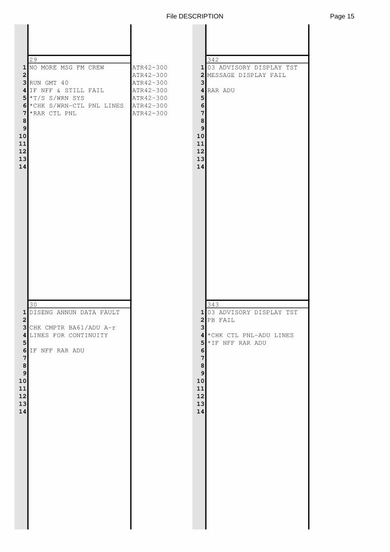
File DESCRIPTION Page 15
29 3421 NO MORE MSG FM CREW ATR42-300 1 03 ADVISORY DISPLAY TST2 ATR42-300 2 MESSAGE DISPLAY FAIL3 RUN GMT 40 ATR42-300 34 IF NFF & STILL FAIL ATR42-300 4 RAR ADU5 *T/S S/WRN SYS ATR42-300 56 *CHK S/WRN-CTL PNL LINES ATR42-300 67 *RAR CTL PNL ATR42-300 78 89 9
10 1011 1112 1213 1314 14
30 3431 DISENG ANNUN DATA FAULT 1 03 ADVISORY DISPLAY TST2 2 PB FAIL3 CHK CMPTR BA61/ADU A-r 34 LINES FOR CONTINUITY 4 *CHK CTL PNL-ADU LINES5 5 *IF NFF RAR ADU6 IF NFF RAR ADU 67 78 89 9
10 1011 1112 1213 1314 14
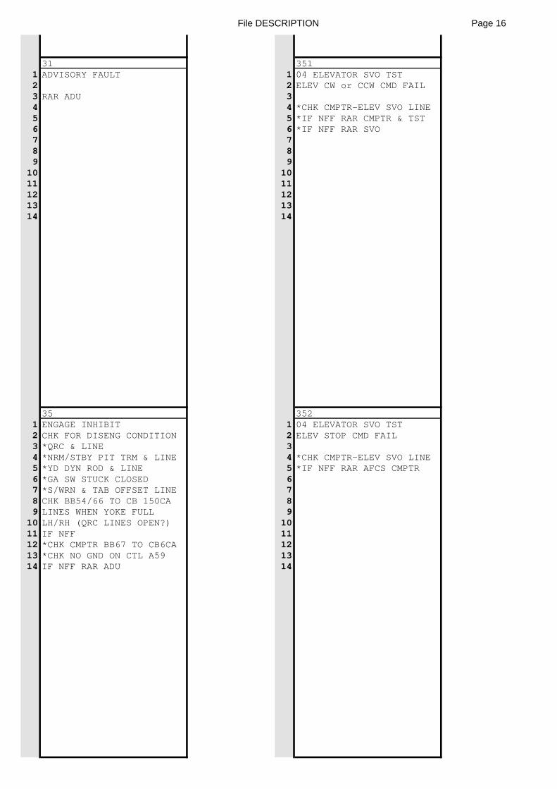
File DESCRIPTION Page 16
31 3511 ADVISORY FAULT 1 04 ELEVATOR SVO TST2 2 ELEV CW or CCW CMD FAIL3 RAR ADU 34 4 *CHK CMPTR-ELEV SVO LINE5 5 *IF NFF RAR CMPTR & TST6 6 *IF NFF RAR SVO7 78 89 9
10 1011 1112 1213 1314 14
35 3521 ENGAGE INHIBIT 1 04 ELEVATOR SVO TST2 CHK FOR DISENG CONDITION 2 ELEV STOP CMD FAIL3 *QRC & LINE 34 *NRM/STBY PIT TRM & LINE 4 *CHK CMPTR-ELEV SVO LINE5 *YD DYN ROD & LINE 5 *IF NFF RAR AFCS CMPTR6 *GA SW STUCK CLOSED 67 *S/WRN & TAB OFFSET LINE 78 CHK BB54/66 TO CB 150CA 89 LINES WHEN YOKE FULL 9
10 LH/RH (QRC LINES OPEN?) 1011 IF NFF 1112 *CHK CMPTR BB67 TO CB6CA 1213 *CHK NO GND ON CTL A59 1314 IF NFF RAR ADU 14
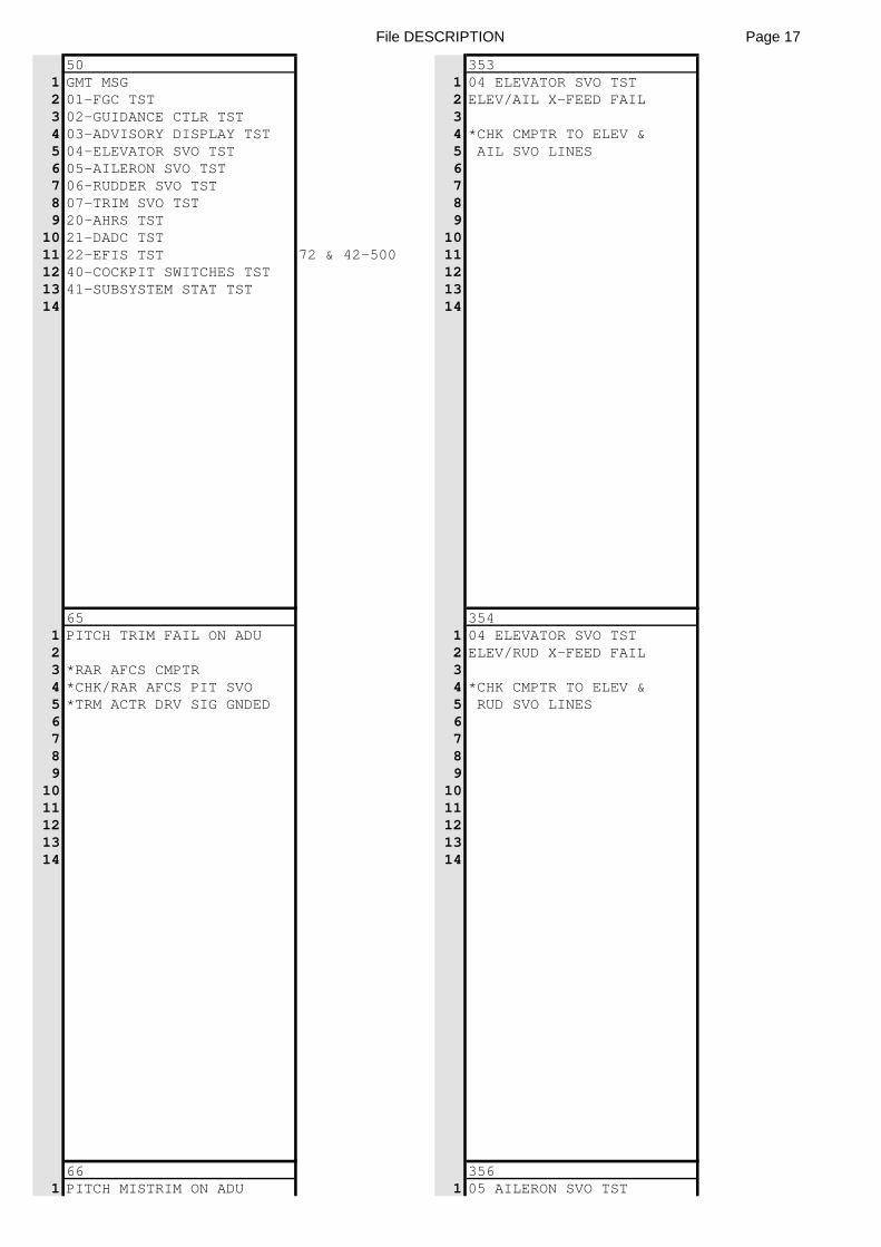
File DESCRIPTION Page 17
50 3531 GMT MSG 1 04 ELEVATOR SVO TST2 01-FGC TST 2 ELEV/AIL X-FEED FAIL3 02-GUIDANCE CTLR TST 34 03-ADVISORY DISPLAY TST 4 *CHK CMPTR TO ELEV &5 04-ELEVATOR SVO TST 5 AIL SVO LINES6 05-AILERON SVO TST 67 06-RUDDER SVO TST 78 07-TRIM SVO TST 89 20-AHRS TST 9
10 21-DADC TST 1011 22-EFIS TST 72 & 42-500 1112 40-COCKPIT SWITCHES TST 1213 41-SUBSYSTEM STAT TST 1314 14
65 3541 PITCH TRIM FAIL ON ADU 1 04 ELEVATOR SVO TST2 2 ELEV/RUD X-FEED FAIL3 *RAR AFCS CMPTR 34 *CHK/RAR AFCS PIT SVO 4 *CHK CMPTR TO ELEV &5 *TRM ACTR DRV SIG GNDED 5 RUD SVO LINES6 67 78 89 9
10 1011 1112 1213 1314 14
66 3561 PITCH MISTRIM ON ADU 1 05 AILERON SVO TST
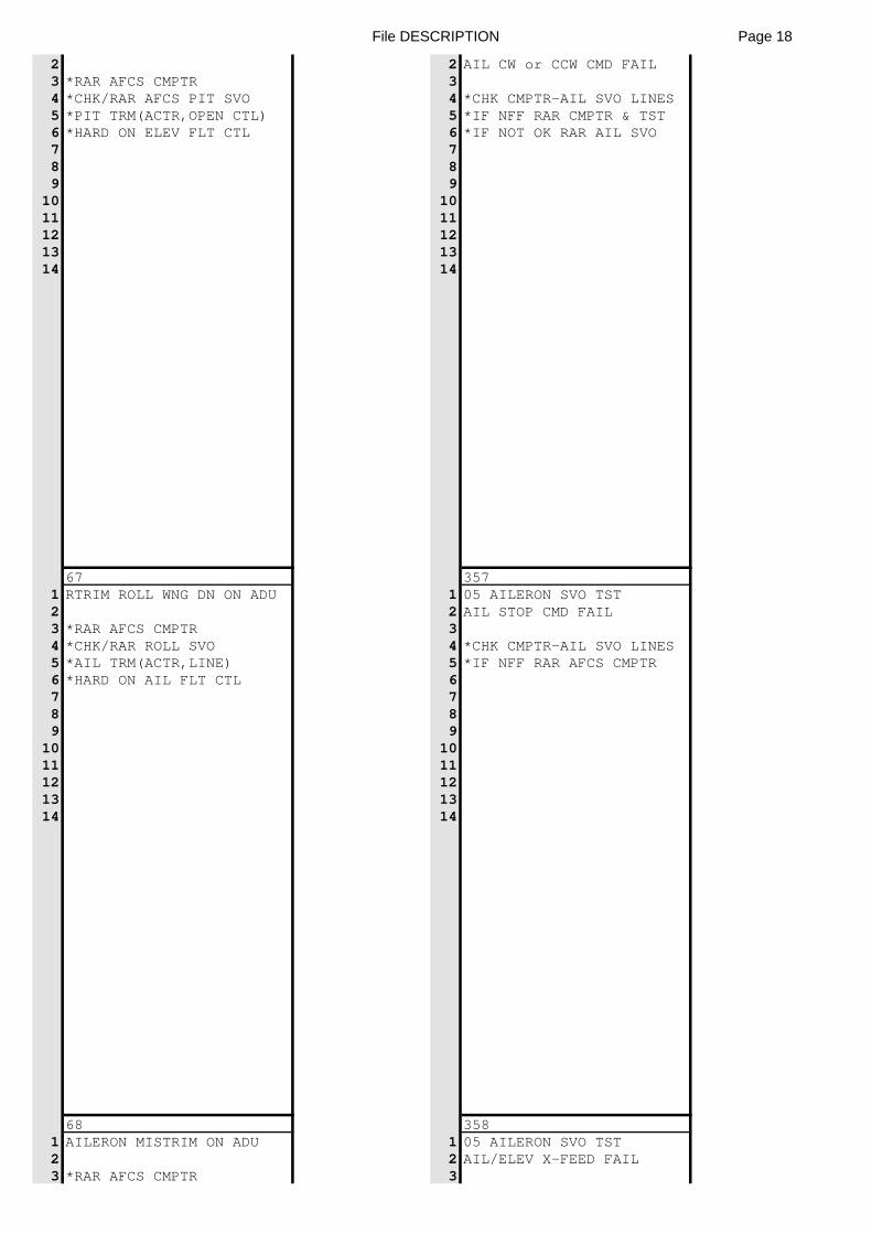
File DESCRIPTION Page 18
2 2 AIL CW or CCW CMD FAIL3 *RAR AFCS CMPTR 34 *CHK/RAR AFCS PIT SVO 4 *CHK CMPTR-AIL SVO LINES5 *PIT TRM(ACTR,OPEN CTL) 5 *IF NFF RAR CMPTR & TST6 *HARD ON ELEV FLT CTL 6 *IF NOT OK RAR AIL SVO7 78 89 9
10 1011 1112 1213 1314 14
67 3571 RTRIM ROLL WNG DN ON ADU 1 05 AILERON SVO TST2 2 AIL STOP CMD FAIL3 *RAR AFCS CMPTR 34 *CHK/RAR ROLL SVO 4 *CHK CMPTR-AIL SVO LINES5 *AIL TRM(ACTR,LINE) 5 *IF NFF RAR AFCS CMPTR6 *HARD ON AIL FLT CTL 67 78 89 9
10 1011 1112 1213 1314 14
68 3581 AILERON MISTRIM ON ADU 1 05 AILERON SVO TST2 2 AIL/ELEV X-FEED FAIL3 *RAR AFCS CMPTR 3
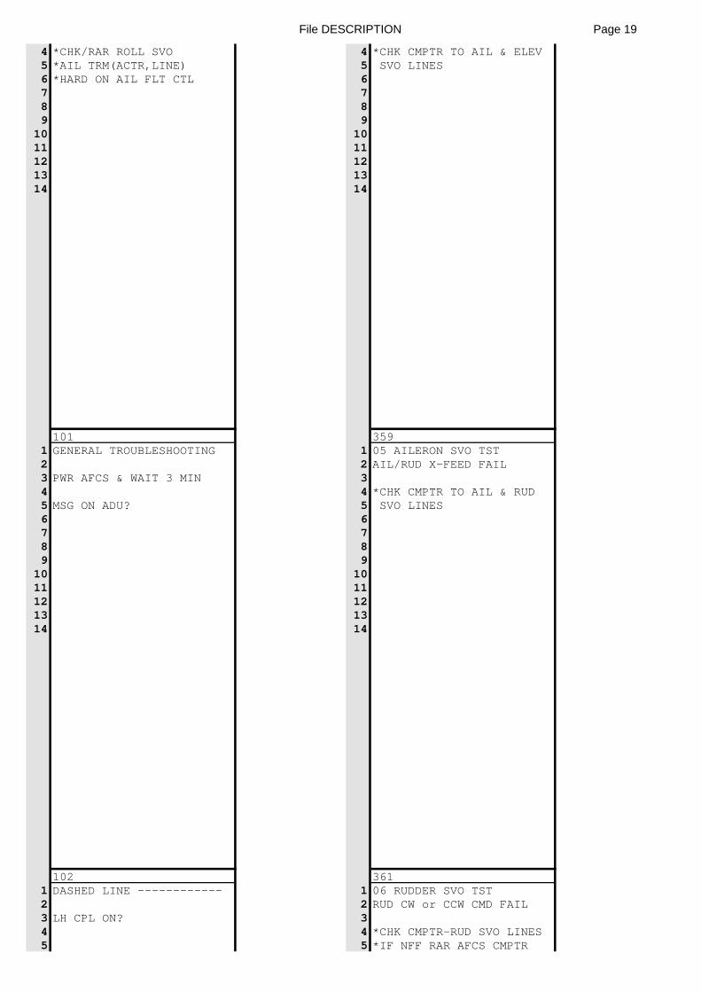
File DESCRIPTION Page 19
4 *CHK/RAR ROLL SVO 4 *CHK CMPTR TO AIL & ELEV5 *AIL TRM(ACTR,LINE) 5 SVO LINES6 *HARD ON AIL FLT CTL 67 78 89 9
10 1011 1112 1213 1314 14
101 3591 GENERAL TROUBLESHOOTING 1 05 AILERON SVO TST2 2 AIL/RUD X-FEED FAIL3 PWR AFCS & WAIT 3 MIN 34 4 *CHK CMPTR TO AIL & RUD5 MSG ON ADU? 5 SVO LINES6 67 78 89 9
10 1011 1112 1213 1314 14
102 3611 DASHED LINE ------------ 1 06 RUDDER SVO TST2 2 RUD CW or CCW CMD FAIL3 LH CPL ON? 34 4 *CHK CMPTR-RUD SVO LINES5 5 *IF NFF RAR AFCS CMPTR
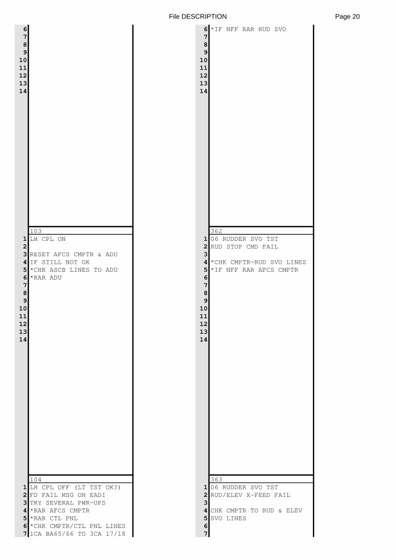
File DESCRIPTION Page 20
6 6 *IF NFF RAR RUD SVO7 78 89 9
10 1011 1112 1213 1314 14
103 3621 LH CPL ON 1 06 RUDDER SVO TST2 2 RUD STOP CMD FAIL3 RESET AFCS CMPTR & ADU 34 IF STILL NOT OK 4 *CHK CMPTR-RUD SVO LINES5 *CHK ASCB LINES TO ADU 5 *IF NFF RAR AFCS CMPTR6 *RAR ADU 67 78 89 9
10 1011 1112 1213 1314 14
104 3631 LH CPL OFF (LT TST OK?) 1 06 RUDDER SVO TST2 FD FAIL MSG ON EADI 2 RUD/ELEV X-FEED FAIL3 TRY SEVERAL PWR-UPS 34 *RAR AFCS CMPTR 4 CHK CMPTR TO RUD & ELEV5 *RAR CTL PNL 5 SVO LINES6 *CHK CMPTR/CTL PNL LINES 67 1CA BA65/66 TO 3CA 17/18 7
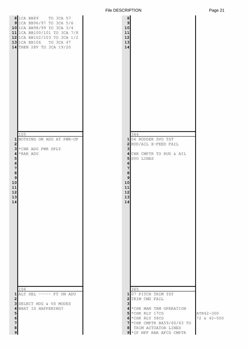
File DESCRIPTION Page 21
8 1CA BB89 TO 3CA 57 89 1CA BB96/97 TO 3CA 5/6 9
10 1CA BB98/99 TO 3CA 3/4 1011 1CA BB100/101 TO 3CA 7/8 1112 1CA BB102/103 TO 3CA 1/2 1213 1CA BB106 TO 3CA 47 1314 THEN 28V TO 3CA 19/20 14
105 3641 NOTHING ON ADU AT PWR-UP 1 06 RUDDER SVO TST2 2 RUD/AIL X-FEED FAIL3 *CHK ADU PWR SPLY 34 *RAR ADU 4 CHK CMPTR TO RUD & AIL5 5 SVO LINES6 67 78 89 9
10 1011 1112 1213 1314 14
106 3651 ALT SEL ----- FT ON ADU 1 07 PITCH TRIM TST2 2 TRIM CMD FAIL3 SELECT HDG & VS MODES 34 WHAT IS HAPPENING? 4 *CHK MAN TRM OPERATION5 5 *CHK RLY 17CG ATR42-3006 6 *CHK RLY 58CG 72 & 42-5007 7 *CHK CMPTR BA59/60/63 TO8 8 TRIM ACTUATOR LINES9 9 *IF NFF RAR AFCS CMPTR
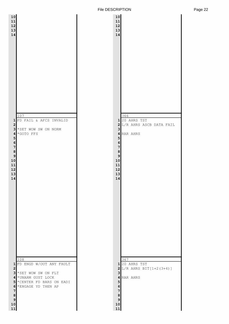
File DESCRIPTION Page 22
10 1011 1112 1213 1314 14
107 3661 FD FAIL & AFCS INVALID 1 20 AHRS TST2 2 L/R AHRS ASCB DATA FAIL3 *SET WOW SW ON NORM 34 *GOTO FFS 4 RAR AHRS5 56 67 78 89 9
10 1011 1112 1213 1314 14
108 3671 FD ENGD W/OUT ANY FAULT 1 20 AHRS TST2 2 L/R AHRS BIT[1+2(3+4)]3 *SET WOW SW ON FLT 34 *UNARM GUST LOCK 4 RAR AHRS5 *CENTER FD BARS ON EADI 56 *ENGAGE YD THEN AP 67 78 89 9
10 1011 11
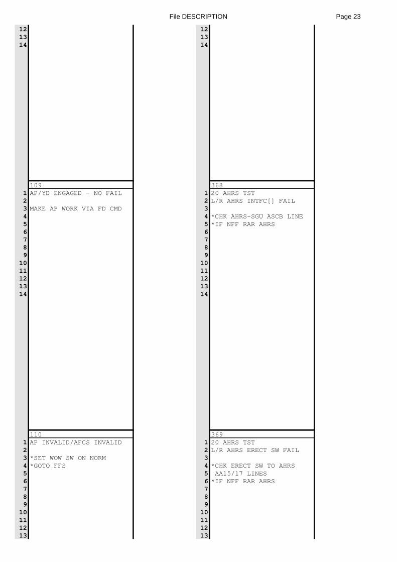
File DESCRIPTION Page 23
12 1213 1314 14
109 3681 AP/YD ENGAGED - NO FAIL 1 20 AHRS TST2 2 L/R AHRS INTFC[] FAIL3 MAKE AP WORK VIA FD CMD 34 4 *CHK AHRS-SGU ASCB LINE5 5 *IF NFF RAR AHRS6 67 78 89 9
10 1011 1112 1213 1314 14
110 3691 AP INVALID/AFCS INVALID 1 20 AHRS TST2 2 L/R AHRS ERECT SW FAIL3 *SET WOW SW ON NORM 34 *GOTO FFS 4 *CHK ERECT SW TO AHRS5 5 AA15/17 LINES6 6 *IF NFF RAR AHRS7 78 89 9
10 1011 1112 1213 13
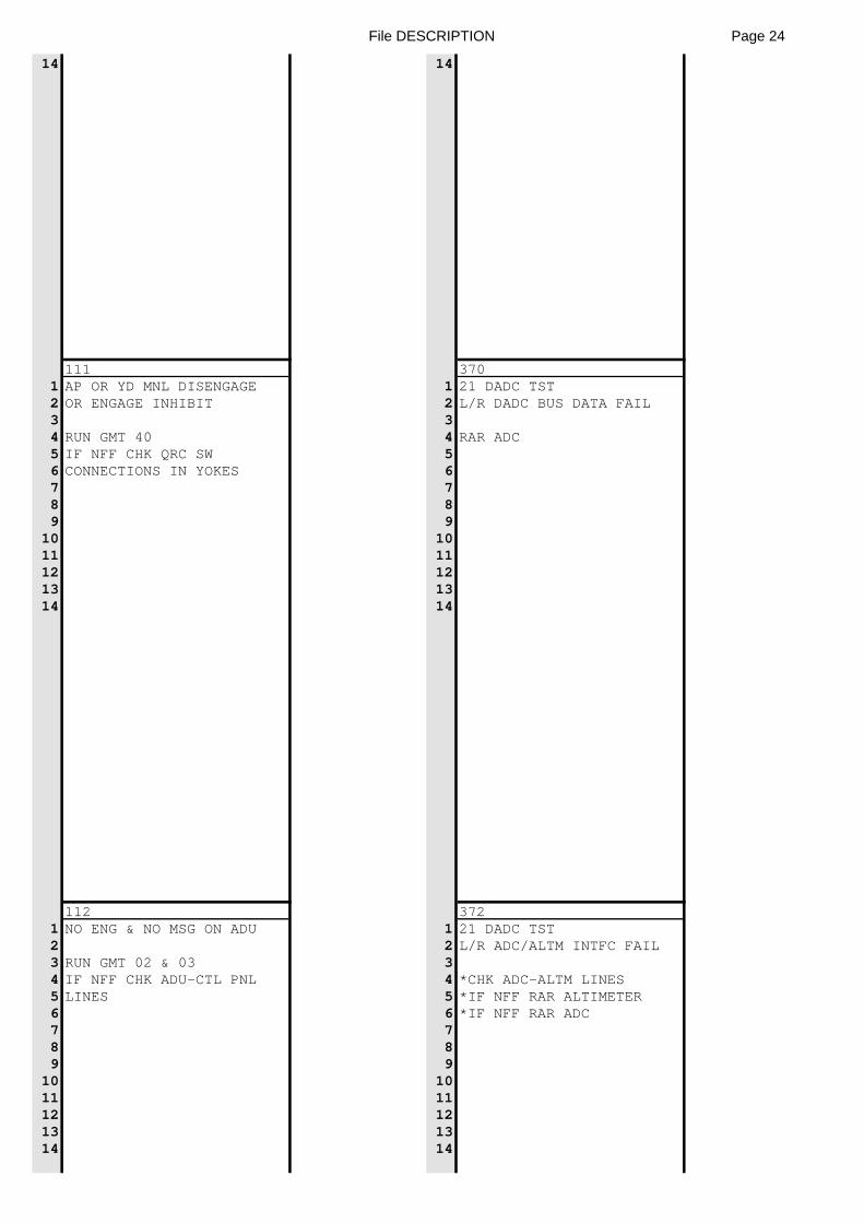
File DESCRIPTION Page 24
14 14
111 3701 AP OR YD MNL DISENGAGE 1 21 DADC TST2 OR ENGAGE INHIBIT 2 L/R DADC BUS DATA FAIL3 34 RUN GMT 40 4 RAR ADC5 IF NFF CHK QRC SW 56 CONNECTIONS IN YOKES 67 78 89 9
10 1011 1112 1213 1314 14
112 3721 NO ENG & NO MSG ON ADU 1 21 DADC TST2 2 L/R ADC/ALTM INTFC FAIL3 RUN GMT 02 & 03 34 IF NFF CHK ADU-CTL PNL 4 *CHK ADC-ALTM LINES5 LINES 5 *IF NFF RAR ALTIMETER6 6 *IF NFF RAR ADC7 78 89 9
10 1011 1112 1213 1314 14
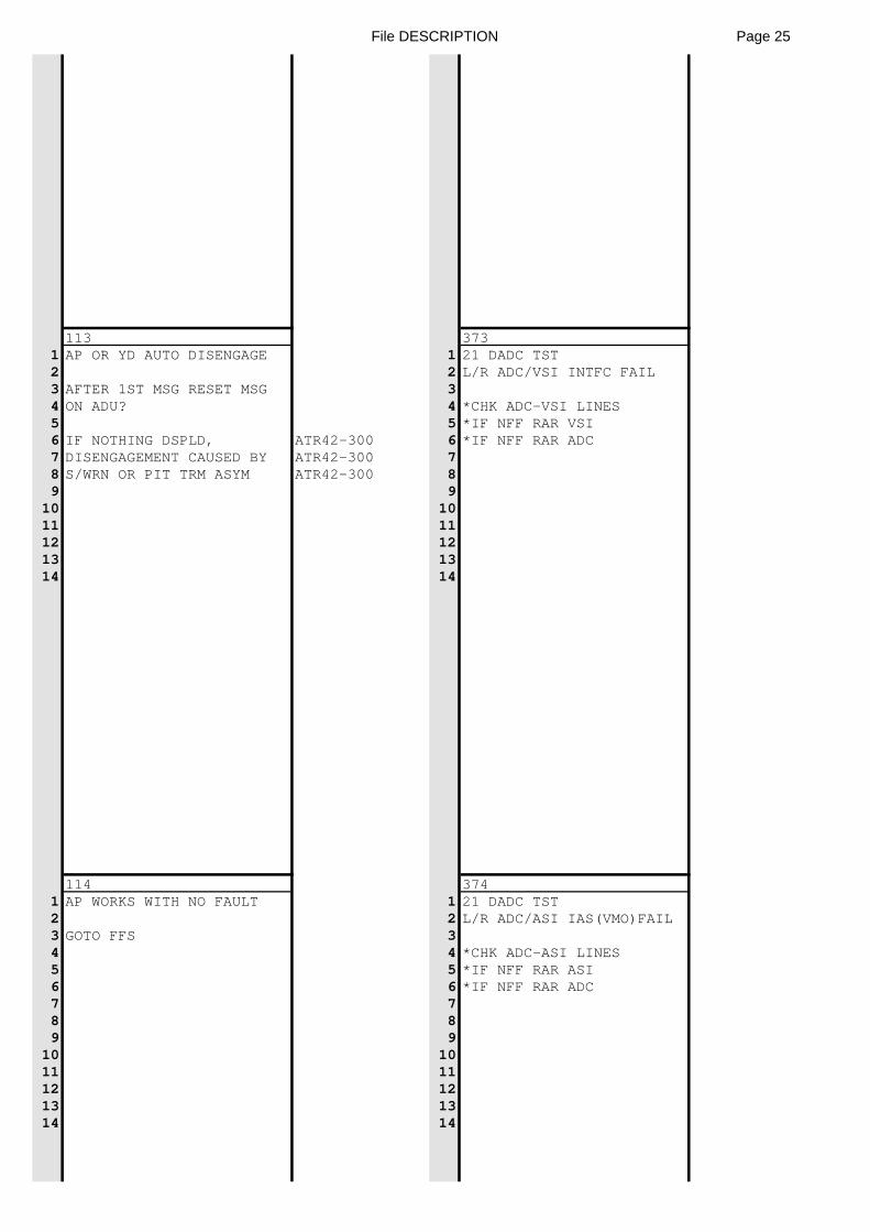
File DESCRIPTION Page 25
113 3731 AP OR YD AUTO DISENGAGE 1 21 DADC TST2 2 L/R ADC/VSI INTFC FAIL3 AFTER 1ST MSG RESET MSG 34 ON ADU? 4 *CHK ADC-VSI LINES5 5 *IF NFF RAR VSI6 IF NOTHING DSPLD, ATR42-300 6 *IF NFF RAR ADC7 DISENGAGEMENT CAUSED BY ATR42-300 78 S/WRN OR PIT TRM ASYM ATR42-300 89 9
10 1011 1112 1213 1314 14
114 3741 AP WORKS WITH NO FAULT 1 21 DADC TST2 2 L/R ADC/ASI IAS(VMO)FAIL3 GOTO FFS 34 4 *CHK ADC-ASI LINES5 5 *IF NFF RAR ASI6 6 *IF NFF RAR ADC7 78 89 9
10 1011 1112 1213 1314 14
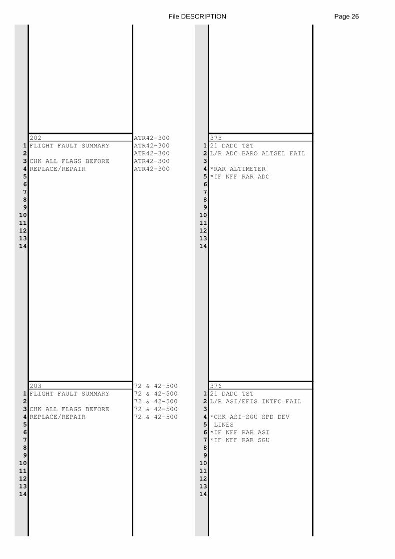
File DESCRIPTION Page 26
202 ATR42-300 3751 FLIGHT FAULT SUMMARY ATR42-300 1 21 DADC TST2 ATR42-300 2 L/R ADC BARO ALTSEL FAIL3 CHK ALL FLAGS BEFORE ATR42-300 34 REPLACE/REPAIR ATR42-300 4 *RAR ALTIMETER5 5 *IF NFF RAR ADC6 67 78 89 9
10 1011 1112 1213 1314 14
203 72 & 42-500 3761 FLIGHT FAULT SUMMARY 72 & 42-500 1 21 DADC TST2 72 & 42-500 2 L/R ASI/EFIS INTFC FAIL3 CHK ALL FLAGS BEFORE 72 & 42-500 34 REPLACE/REPAIR 72 & 42-500 4 *CHK ASI-SGU SPD DEV5 5 LINES6 6 *IF NFF RAR ASI7 7 *IF NFF RAR SGU8 89 9
10 1011 1112 1213 1314 14
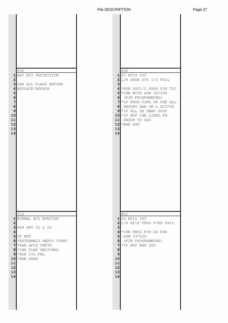
File DESCRIPTION Page 27
205 4001 ADC BIT DEFINITION 1 22 EFIS TST2 2 L/R SNSR STS 1/2 FAIL3 CHK ALL FLAGS BEFORE 34 REPLACE/REPAIR 4 *RUN SGU1/2 PROG PIN TST5 5 *CHK WITH ASM 3472006 6 (PIN PROGRAMMING)7 7 *IF PROG PINS OK CHK ALL8 8 SNSORS ARE ON & ACTIVE9 9 *IF ALL OK SWAP SGUS
10 10 *IF NFF CHK LINES FM11 11 SNSOR TO SGU12 12 *RAR SGU13 1314 14
210 4011 NORMAL ACC MONITOR 1 22 EFIS TST2 2 L/R EFIS PROG PINS FAIL3 RUN GMT 02 & 20 34 4 *CHK PROG PIN AS PER5 IF NFF 5 ASM 3472006 *EXTREMELY HEAVY TURB? 6 (PIN PROGRAMMING)7 *RAR AFCS CMPTR 7 *IF NFF RAR SGU8 *CHK FLAP SWITCHES 89 *RAR CTL PNL 9
10 *RAR AHRS 1011 1112 1213 1314 14
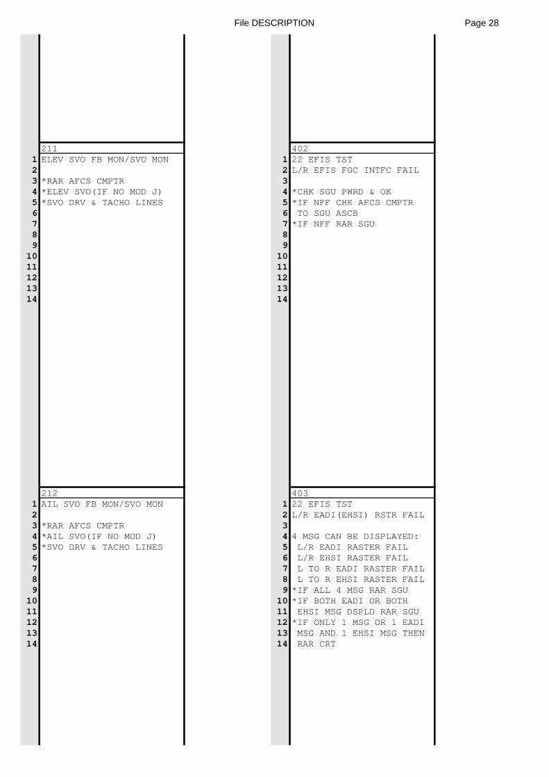
File DESCRIPTION Page 28
211 4021 ELEV SVO FB MON/SVO MON 1 22 EFIS TST2 2 L/R EFIS FGC INTFC FAIL3 *RAR AFCS CMPTR 34 *ELEV SVO(IF NO MOD J) 4 *CHK SGU PWRD & OK5 *SVO DRV & TACHO LINES 5 *IF NFF CHK AFCS CMPTR6 6 TO SGU ASCB7 7 *IF NFF RAR SGU8 89 9
10 1011 1112 1213 1314 14
212 4031 AIL SVO FB MON/SVO MON 1 22 EFIS TST2 2 L/R EADI(EHSI) RSTR FAIL3 *RAR AFCS CMPTR 34 *AIL SVO(IF NO MOD J) 4 4 MSG CAN BE DISPLAYED:5 *SVO DRV & TACHO LINES 5 L/R EADI RASTER FAIL6 6 L/R EHSI RASTER FAIL7 7 L TO R EADI RASTER FAIL8 8 L TO R EHSI RASTER FAIL9 9 *IF ALL 4 MSG RAR SGU
10 10 *IF BOTH EADI OR BOTH11 11 EHSI MSG DSPLD RAR SGU12 12 *IF ONLY 1 MSG OR 1 EADI13 13 MSG AND 1 EHSI MSG THEN14 14 RAR CRT
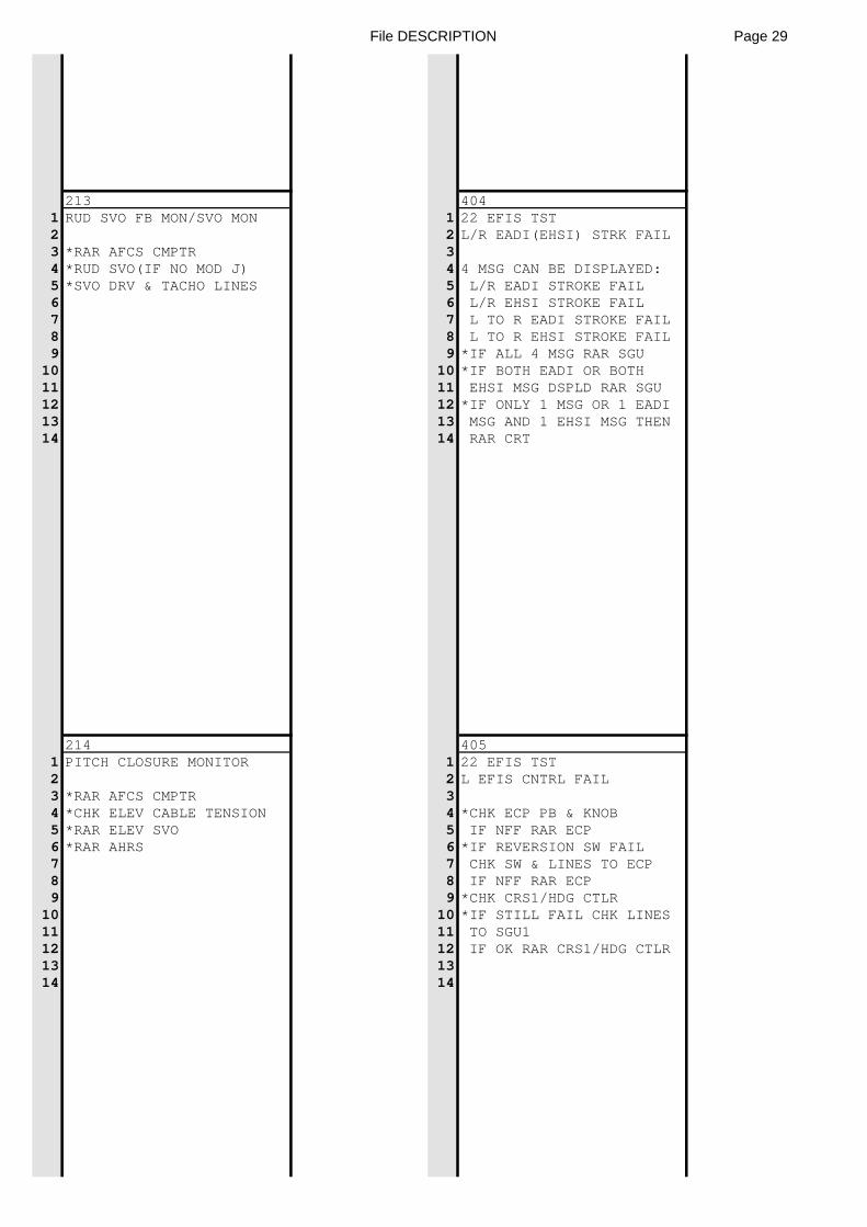
File DESCRIPTION Page 29
213 4041 RUD SVO FB MON/SVO MON 1 22 EFIS TST2 2 L/R EADI(EHSI) STRK FAIL3 *RAR AFCS CMPTR 34 *RUD SVO(IF NO MOD J) 4 4 MSG CAN BE DISPLAYED:5 *SVO DRV & TACHO LINES 5 L/R EADI STROKE FAIL6 6 L/R EHSI STROKE FAIL7 7 L TO R EADI STROKE FAIL8 8 L TO R EHSI STROKE FAIL9 9 *IF ALL 4 MSG RAR SGU
10 10 *IF BOTH EADI OR BOTH11 11 EHSI MSG DSPLD RAR SGU12 12 *IF ONLY 1 MSG OR 1 EADI13 13 MSG AND 1 EHSI MSG THEN14 14 RAR CRT
214 4051 PITCH CLOSURE MONITOR 1 22 EFIS TST2 2 L EFIS CNTRL FAIL3 *RAR AFCS CMPTR 34 *CHK ELEV CABLE TENSION 4 *CHK ECP PB & KNOB5 *RAR ELEV SVO 5 IF NFF RAR ECP6 *RAR AHRS 6 *IF REVERSION SW FAIL7 7 CHK SW & LINES TO ECP8 8 IF NFF RAR ECP9 9 *CHK CRS1/HDG CTLR
10 10 *IF STILL FAIL CHK LINES11 11 TO SGU112 12 IF OK RAR CRS1/HDG CTLR13 1314 14
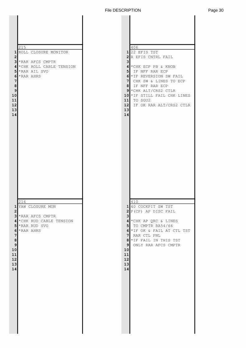
File DESCRIPTION Page 30
215 4061 ROLL CLOSURE MONITOR 1 22 EFIS TST2 2 R EFIS CNTRL FAIL3 *RAR AFCS CMPTR 34 *CHK ROLL CABLE TENSION 4 *CHK ECP PB & KNOB5 *RAR AIL SVO 5 IF NFF RAR ECP6 *RAR AHRS 6 *IF REVERSION SW FAIL7 7 CHK SW & LINES TO ECP8 8 IF NFF RAR ECP9 9 *CHK ALT/CRS2 CTLR
10 10 *IF STILL FAIL CHK LINES11 11 TO SGU212 12 IF OK RAR ALT/CRS2 CTLR13 1314 14
216 4101 YAW CLOSURE MON 1 40 COCKPIT SW TST2 2 P(CP) AP DISC FAIL3 *RAR AFCS CMPTR 34 *CHK RUD CABLE TENSION 4 *CHK AP QRC & LINES5 *RAR RUD SVO 5 TO CMPTR BA54/666 *RAR AHRS 6 *IF OK & FAIL AT CTL TST7 7 RAR CTL PNL8 8 *IF FAIL IN THIS TST9 9 ONLY RAR AFCS CMPTR
10 1011 1112 1213 1314 14
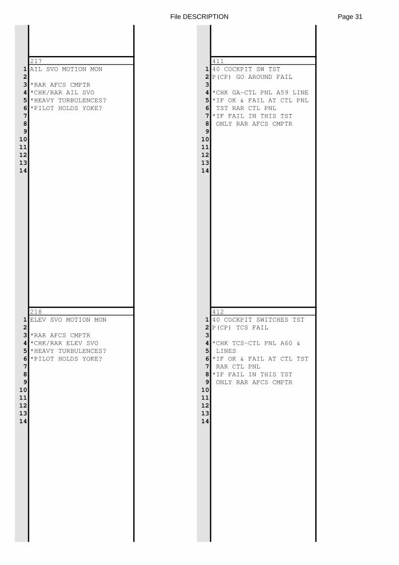
File DESCRIPTION Page 31
217 4111 AIL SVO MOTION MON 1 40 COCKPIT SW TST2 2 P(CP) GO AROUND FAIL3 *RAR AFCS CMPTR 34 *CHK/RAR AIL SVO 4 *CHK GA-CTL PNL A59 LINE5 *HEAVY TURBULENCES? 5 *IF OK & FAIL AT CTL PNL6 *PILOT HOLDS YOKE? 6 TST RAR CTL PNL7 7 *IF FAIL IN THIS TST8 8 ONLY RAR AFCS CMPTR9 9
10 1011 1112 1213 1314 14
218 4121 ELEV SVO MOTION MON 1 40 COCKPIT SWITCHES TST2 2 P(CP) TCS FAIL3 *RAR AFCS CMPTR 34 *CHK/RAR ELEV SVO 4 *CHK TCS-CTL PNL A60 &5 *HEAVY TURBULENCES? 5 LINES6 *PILOT HOLDS YOKE? 6 *IF OK & FAIL AT CTL TST7 7 RAR CTL PNL8 8 *IF FAIL IN THIS TST9 9 ONLY RAR AFCS CMPTR
10 1011 1112 1213 1314 14
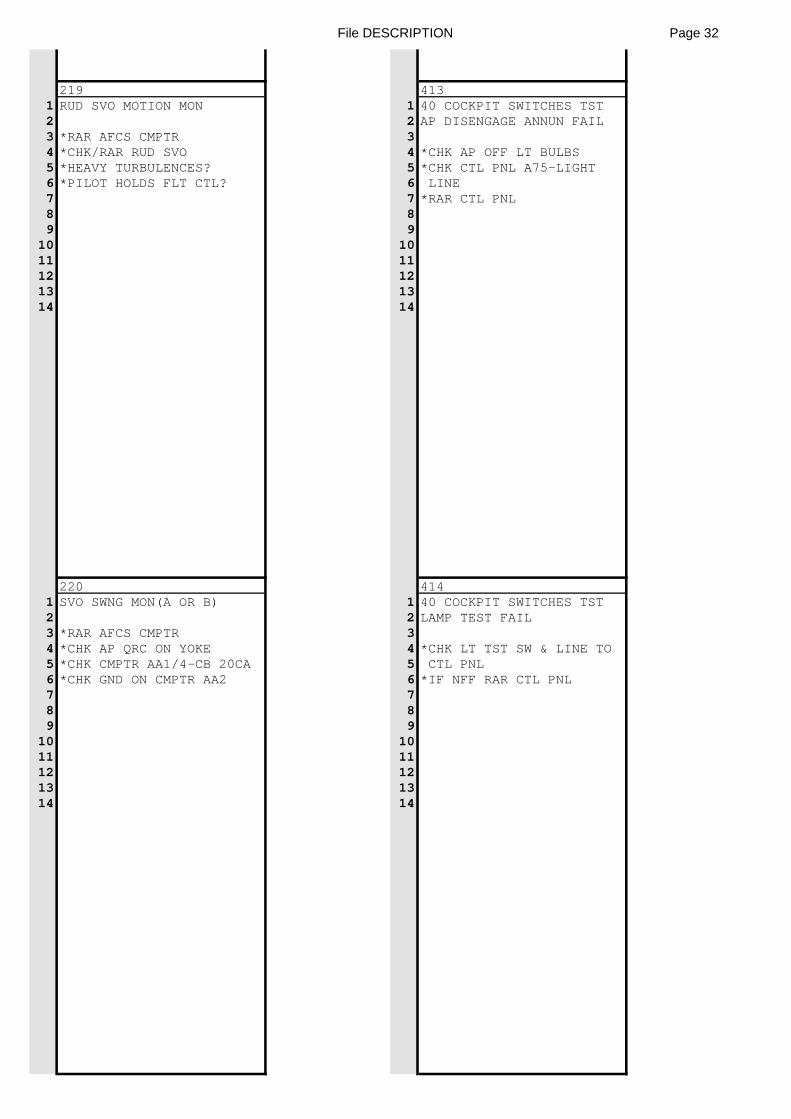
File DESCRIPTION Page 32
219 4131 RUD SVO MOTION MON 1 40 COCKPIT SWITCHES TST2 2 AP DISENGAGE ANNUN FAIL3 *RAR AFCS CMPTR 34 *CHK/RAR RUD SVO 4 *CHK AP OFF LT BULBS5 *HEAVY TURBULENCES? 5 *CHK CTL PNL A75-LIGHT6 *PILOT HOLDS FLT CTL? 6 LINE7 7 *RAR CTL PNL8 89 9
10 1011 1112 1213 1314 14
220 4141 SVO SWNG MON(A OR B) 1 40 COCKPIT SWITCHES TST2 2 LAMP TEST FAIL3 *RAR AFCS CMPTR 34 *CHK AP QRC ON YOKE 4 *CHK LT TST SW & LINE TO5 *CHK CMPTR AA1/4-CB 20CA 5 CTL PNL6 *CHK GND ON CMPTR AA2 6 *IF NFF RAR CTL PNL7 78 89 9
10 1011 1112 1213 1314 14
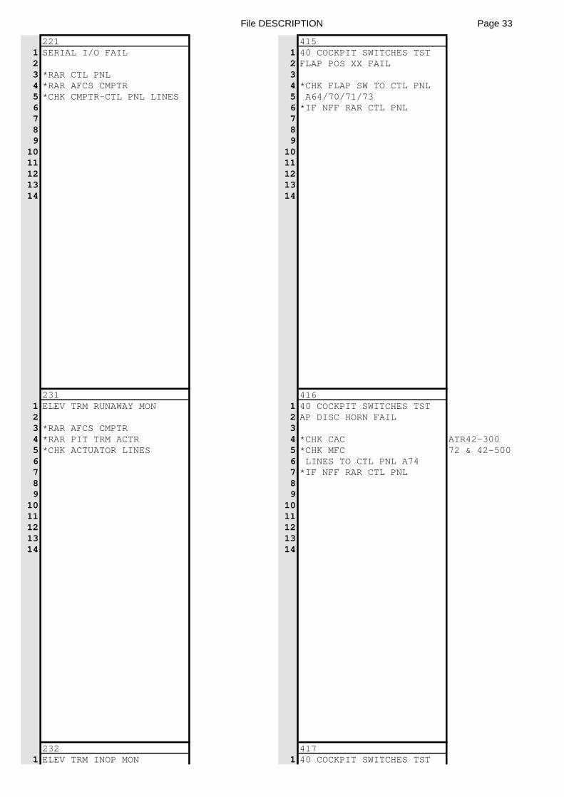
File DESCRIPTION Page 33
221 4151 SERIAL I/O FAIL 1 40 COCKPIT SWITCHES TST2 2 FLAP POS XX FAIL3 *RAR CTL PNL 34 *RAR AFCS CMPTR 4 *CHK FLAP SW TO CTL PNL5 *CHK CMPTR-CTL PNL LINES 5 A64/70/71/736 6 *IF NFF RAR CTL PNL7 78 89 9
10 1011 1112 1213 1314 14
231 4161 ELEV TRM RUNAWAY MON 1 40 COCKPIT SWITCHES TST2 2 AP DISC HORN FAIL3 *RAR AFCS CMPTR 34 *RAR PIT TRM ACTR 4 *CHK CAC ATR42-3005 *CHK ACTUATOR LINES 5 *CHK MFC 72 & 42-5006 6 LINES TO CTL PNL A747 7 *IF NFF RAR CTL PNL8 89 9
10 1011 1112 1213 1314 14
232 4171 ELEV TRM INOP MON 1 40 COCKPIT SWITCHES TST
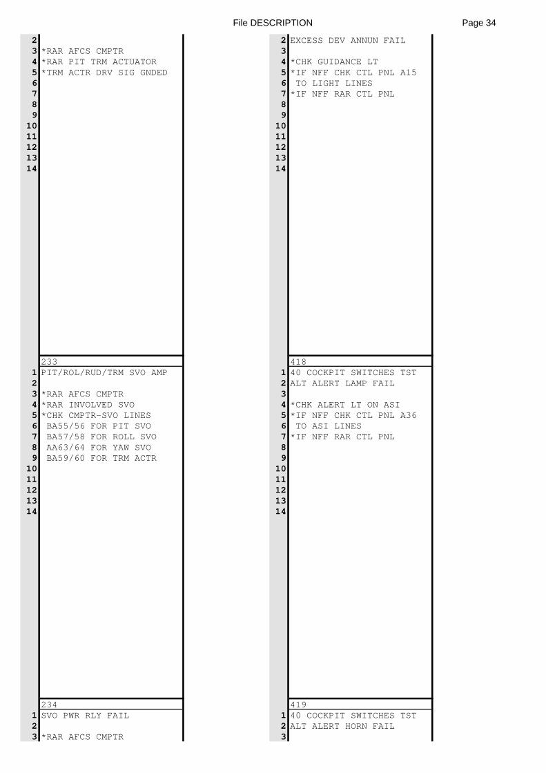
File DESCRIPTION Page 34
2 2 EXCESS DEV ANNUN FAIL3 *RAR AFCS CMPTR 34 *RAR PIT TRM ACTUATOR 4 *CHK GUIDANCE LT5 *TRM ACTR DRV SIG GNDED 5 *IF NFF CHK CTL PNL A156 6 TO LIGHT LINES7 7 *IF NFF RAR CTL PNL8 89 9
10 1011 1112 1213 1314 14
233 4181 PIT/ROL/RUD/TRM SVO AMP 1 40 COCKPIT SWITCHES TST2 2 ALT ALERT LAMP FAIL3 *RAR AFCS CMPTR 34 *RAR INVOLVED SVO 4 *CHK ALERT LT ON ASI5 *CHK CMPTR-SVO LINES 5 *IF NFF CHK CTL PNL A366 BA55/56 FOR PIT SVO 6 TO ASI LINES7 BA57/58 FOR ROLL SVO 7 *IF NFF RAR CTL PNL8 AA63/64 FOR YAW SVO 89 BA59/60 FOR TRM ACTR 9
10 1011 1112 1213 1314 14
234 4191 SVO PWR RLY FAIL 1 40 COCKPIT SWITCHES TST2 2 ALT ALERT HORN FAIL3 *RAR AFCS CMPTR 3
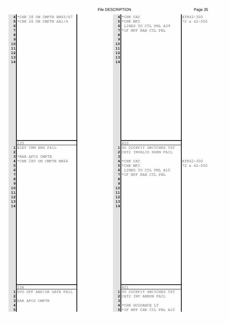
File DESCRIPTION Page 35
4 *CHK 28 ON CMPTR BB65/67 4 *CHK CAC ATR42-3005 *CHK 28 ON CMPTR AA1/4 5 *CHK MFC 72 & 42-5006 6 LINES TO CTL PNL A397 7 *IF NFF RAR CTL PNL8 89 9
10 1011 1112 1213 1314 14
235 4201 ELEV TRM ENG FAIL 1 40 COCKPIT SWITCHES TST2 2 CAT2 INVALID HORN FAIL3 *RAR AFCS CMPTR 34 *CHK 28V ON CMPTR BB66 4 *CHK CAC ATR42-3005 5 *CHK MFC 72 & 42-5006 6 LINES TO CTL PNL A107 7 *IF NFF RAR CTL PNL8 89 9
10 1011 1112 1213 1314 14
236 4211 SVO OFF AND/OR GATE FAIL 1 40 COCKPIT SWITCHES TST2 2 CAT2 INV ANNUN FAIL3 RAR AFCS CMPTR 34 4 *CHK GUIDANCE LT5 5 *IF NFF CHK CTL PNL A10
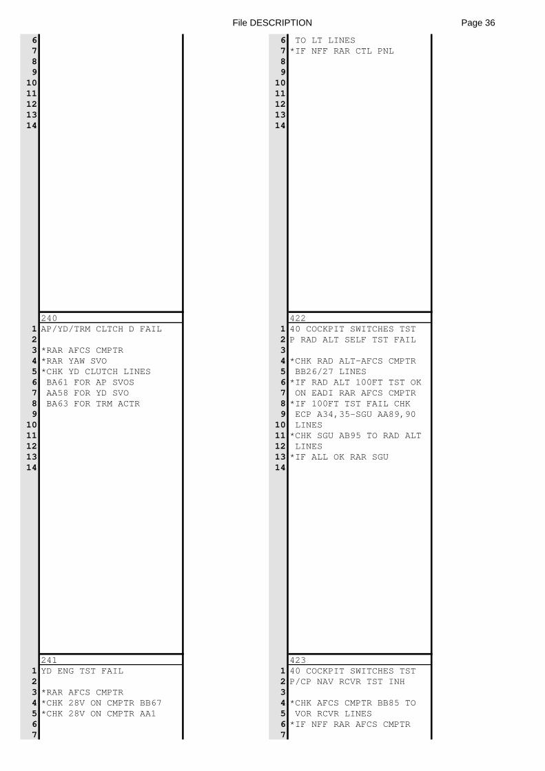
File DESCRIPTION Page 36
6 6 TO LT LINES7 7 *IF NFF RAR CTL PNL8 89 9
10 1011 1112 1213 1314 14
240 4221 AP/YD/TRM CLTCH D FAIL 1 40 COCKPIT SWITCHES TST2 2 P RAD ALT SELF TST FAIL3 *RAR AFCS CMPTR 34 *RAR YAW SVO 4 *CHK RAD ALT-AFCS CMPTR5 *CHK YD CLUTCH LINES 5 BB26/27 LINES6 BA61 FOR AP SVOS 6 *IF RAD ALT 100FT TST OK7 AA58 FOR YD SVO 7 ON EADI RAR AFCS CMPTR8 BA63 FOR TRM ACTR 8 *IF 100FT TST FAIL CHK9 9 ECP A34,35-SGU AA89,90
10 10 LINES11 11 *CHK SGU AB95 TO RAD ALT12 12 LINES13 13 *IF ALL OK RAR SGU14 14
241 4231 YD ENG TST FAIL 1 40 COCKPIT SWITCHES TST2 2 P/CP NAV RCVR TST INH3 *RAR AFCS CMPTR 34 *CHK 28V ON CMPTR BB67 4 *CHK AFCS CMPTR BB85 TO5 *CHK 28V ON CMPTR AA1 5 VOR RCVR LINES6 6 *IF NFF RAR AFCS CMPTR7 7
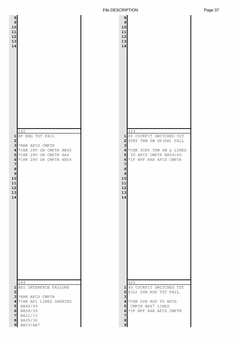
File DESCRIPTION Page 37
8 89 9
10 1011 1112 1213 1314 14
242 4241 AP ENG TST FAIL 1 40 COCKPIT SWITCHES TST2 2 STBY TRM SW UP(DN) FAIL3 *RAR AFCS CMPTR 34 *CHK 28V ON CMPTR BB65 4 *CHK STBY TRM SW & LINES5 *CHK 28V ON CMPTR AA4 5 TO AFCS CMPTR BB54/666 *CHK 28V ON CMPTR BB54 6 *IF NFF RAR AFCS CMPTR7 78 89 9
10 1011 1112 1213 1314 14
243 4251 ADI INTERFACE FAILURE 1 40 COCKPIT SWITCHES TST2 2 R(L) DYN ROD TST FAIL3 *RAR AFCS CMPTR 34 *CHK ADI LINES SHORTED 4 *CHK DYN ROD TO AFCS5 BB48/49 5 CMPTR BB67 LINES6 BB58/59 6 *IF NFF RAR AFCS CMPTR7 BA12/13 78 BA35/36 89 BB53/AA7 9
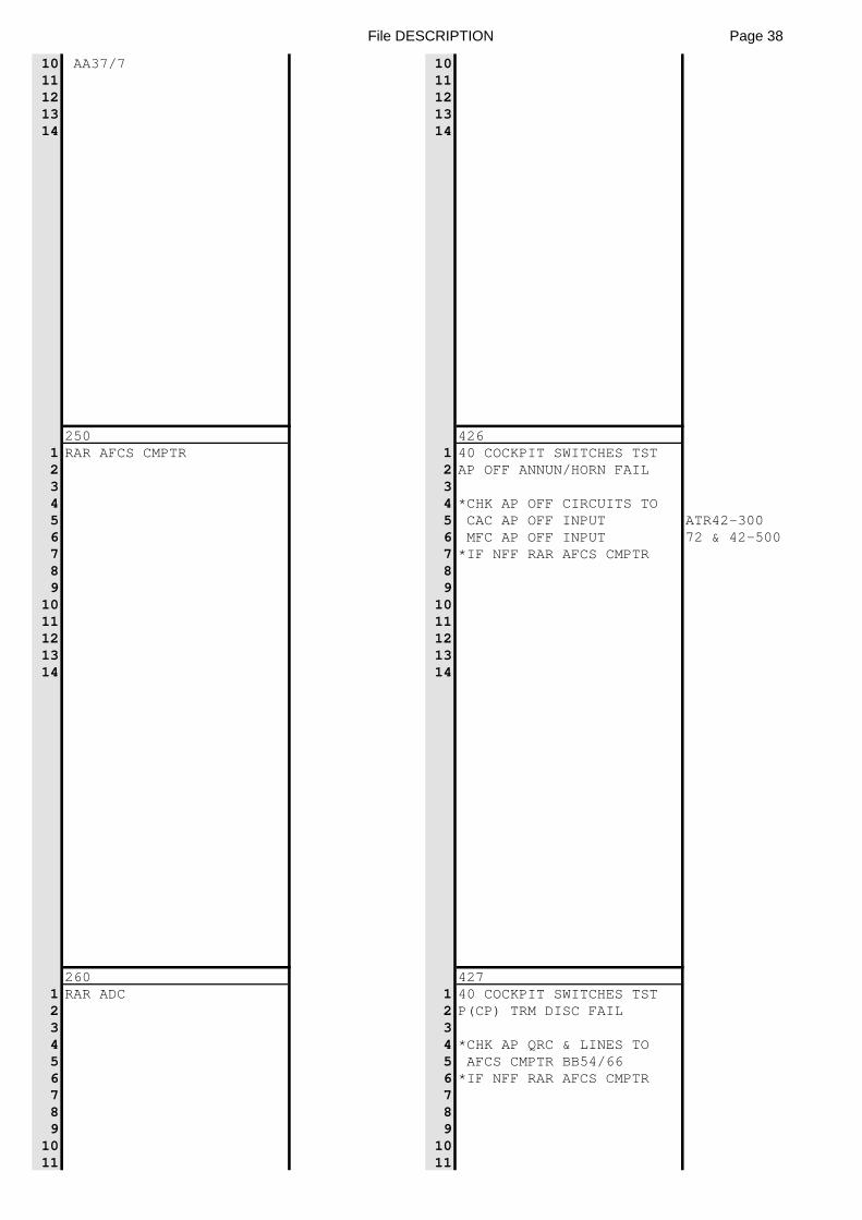
File DESCRIPTION Page 38
10 AA37/7 1011 1112 1213 1314 14
250 4261 RAR AFCS CMPTR 1 40 COCKPIT SWITCHES TST2 2 AP OFF ANNUN/HORN FAIL3 34 4 *CHK AP OFF CIRCUITS TO5 5 CAC AP OFF INPUT ATR42-3006 6 MFC AP OFF INPUT 72 & 42-5007 7 *IF NFF RAR AFCS CMPTR8 89 9
10 1011 1112 1213 1314 14
260 4271 RAR ADC 1 40 COCKPIT SWITCHES TST2 2 P(CP) TRM DISC FAIL3 34 4 *CHK AP QRC & LINES TO5 5 AFCS CMPTR BB54/666 6 *IF NFF RAR AFCS CMPTR7 78 89 9
10 1011 11
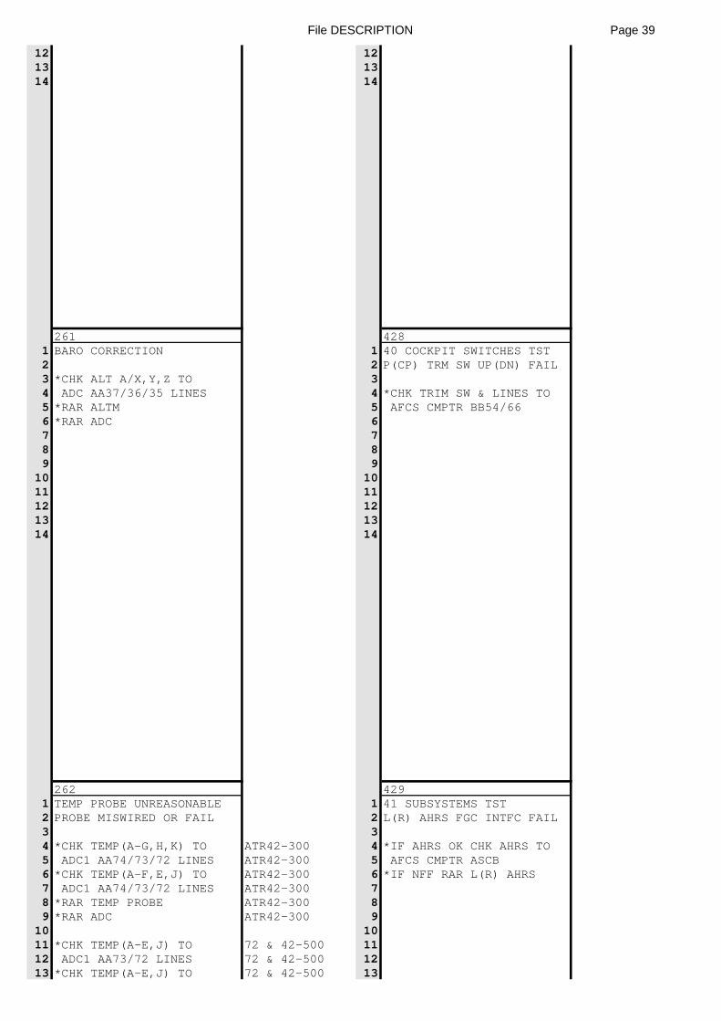
File DESCRIPTION Page 39
12 1213 1314 14
261 4281 BARO CORRECTION 1 40 COCKPIT SWITCHES TST2 2 P(CP) TRM SW UP(DN) FAIL3 *CHK ALT A/X,Y,Z TO 34 ADC AA37/36/35 LINES 4 *CHK TRIM SW & LINES TO5 *RAR ALTM 5 AFCS CMPTR BB54/666 *RAR ADC 67 78 89 9
10 1011 1112 1213 1314 14
262 4291 TEMP PROBE UNREASONABLE 1 41 SUBSYSTEMS TST2 PROBE MISWIRED OR FAIL 2 L(R) AHRS FGC INTFC FAIL3 34 *CHK TEMP(A-G,H,K) TO ATR42-300 4 *IF AHRS OK CHK AHRS TO5 ADC1 AA74/73/72 LINES ATR42-300 5 AFCS CMPTR ASCB6 *CHK TEMP(A-F,E,J) TO ATR42-300 6 *IF NFF RAR L(R) AHRS7 ADC1 AA74/73/72 LINES ATR42-300 78 *RAR TEMP PROBE ATR42-300 89 *RAR ADC ATR42-300 9
10 1011 *CHK TEMP(A-E,J) TO 72 & 42-500 1112 ADC1 AA73/72 LINES 72 & 42-500 1213 *CHK TEMP(A-E,J) TO 72 & 42-500 13
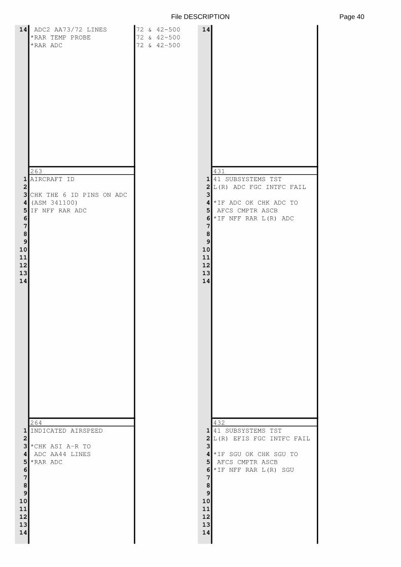
File DESCRIPTION Page 40
14 ADC2 AA73/72 LINES 72 & 42-500 14*RAR TEMP PROBE 72 & 42-500*RAR ADC 72 & 42-500
263 4311 AIRCRAFT ID 1 41 SUBSYSTEMS TST2 2 L(R) ADC FGC INTFC FAIL3 CHK THE 6 ID PINS ON ADC 34 (ASM 341100) 4 *IF ADC OK CHK ADC TO5 IF NFF RAR ADC 5 AFCS CMPTR ASCB6 6 *IF NFF RAR L(R) ADC7 78 89 9
10 1011 1112 1213 1314 14
264 4321 INDICATED AIRSPEED 1 41 SUBSYSTEMS TST2 2 L(R) EFIS FGC INTFC FAIL3 *CHK ASI A-R TO 34 ADC AA44 LINES 4 *IF SGU OK CHK SGU TO5 *RAR ADC 5 AFCS CMPTR ASCB6 6 *IF NFF RAR L(R) SGU7 78 89 9
10 1011 1112 1213 1314 14
File DESCRIPTION Page 41
2651 ALT FINE RESOLVER23 *CHK ASI(A-U,V) TO4 ADC(AA26/27) LINES5 *RAR ADC6789
1011121314
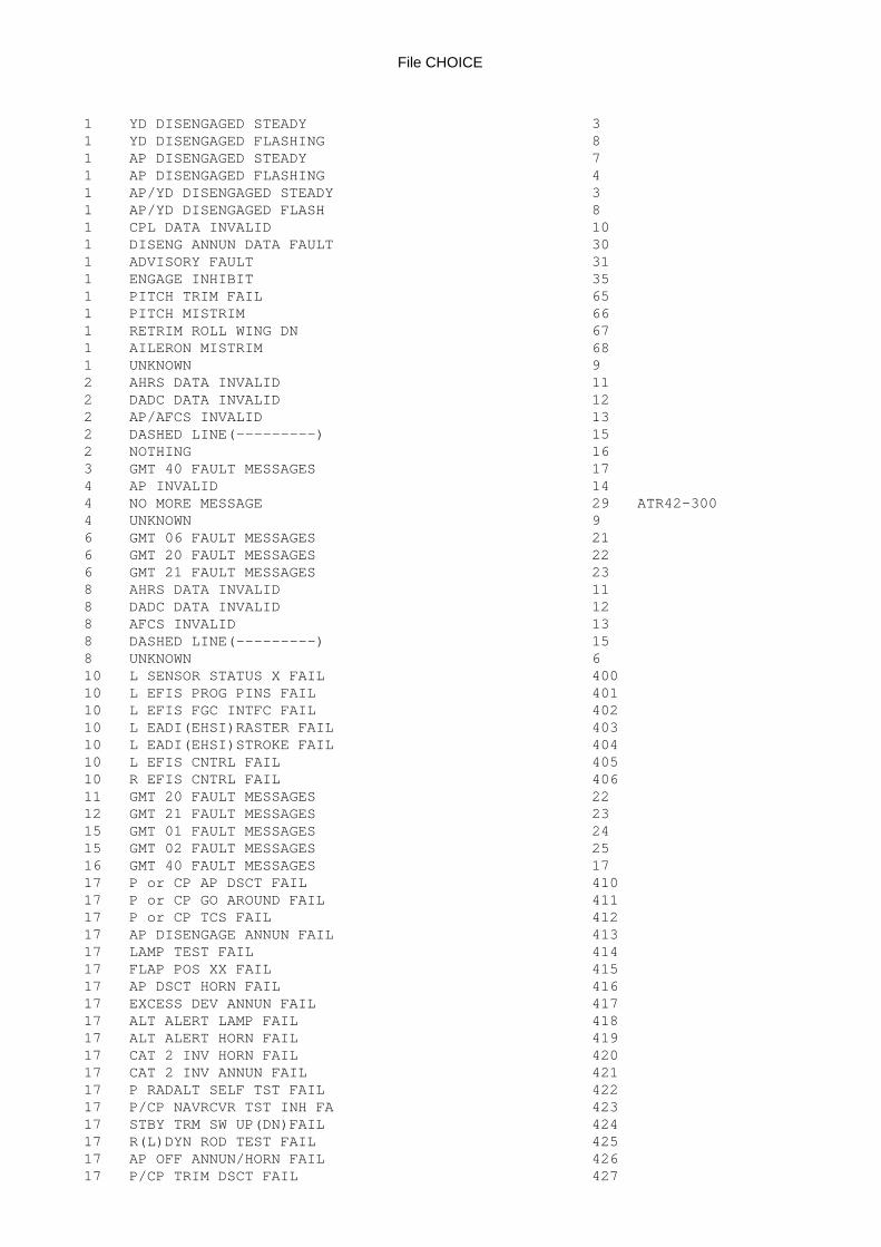
File CHOICE
1 YD DISENGAGED STEADY 31 YD DISENGAGED FLASHING 81 AP DISENGAGED STEADY 71 AP DISENGAGED FLASHING 41 AP/YD DISENGAGED STEADY 31 AP/YD DISENGAGED FLASH 81 CPL DATA INVALID 101 DISENG ANNUN DATA FAULT 301 ADVISORY FAULT 311 ENGAGE INHIBIT 351 PITCH TRIM FAIL 651 PITCH MISTRIM 661 RETRIM ROLL WING DN 671 AILERON MISTRIM 681 UNKNOWN 92 AHRS DATA INVALID 112 DADC DATA INVALID 122 AP/AFCS INVALID 132 DASHED LINE(---------) 152 NOTHING 163 GMT 40 FAULT MESSAGES 174 AP INVALID 144 NO MORE MESSAGE 29 ATR42-3004 UNKNOWN 96 GMT 06 FAULT MESSAGES 216 GMT 20 FAULT MESSAGES 226 GMT 21 FAULT MESSAGES 238 AHRS DATA INVALID 118 DADC DATA INVALID 128 AFCS INVALID 138 DASHED LINE(---------) 158 UNKNOWN 610 L SENSOR STATUS X FAIL 40010 L EFIS PROG PINS FAIL 40110 L EFIS FGC INTFC FAIL 40210 L EADI(EHSI)RASTER FAIL 40310 L EADI(EHSI)STROKE FAIL 40410 L EFIS CNTRL FAIL 40510 R EFIS CNTRL FAIL 40611 GMT 20 FAULT MESSAGES 2212 GMT 21 FAULT MESSAGES 2315 GMT 01 FAULT MESSAGES 2415 GMT 02 FAULT MESSAGES 2516 GMT 40 FAULT MESSAGES 1717 P or CP AP DSCT FAIL 41017 P or CP GO AROUND FAIL 41117 P or CP TCS FAIL 41217 AP DISENGAGE ANNUN FAIL 41317 LAMP TEST FAIL 41417 FLAP POS XX FAIL 41517 AP DSCT HORN FAIL 41617 EXCESS DEV ANNUN FAIL 41717 ALT ALERT LAMP FAIL 41817 ALT ALERT HORN FAIL 41917 CAT 2 INV HORN FAIL 42017 CAT 2 INV ANNUN FAIL 42117 P RADALT SELF TST FAIL 42217 P/CP NAVRCVR TST INH FA 42317 STBY TRM SW UP(DN)FAIL 42417 R(L)DYN ROD TEST FAIL 42517 AP OFF ANNUN/HORN FAIL 42617 P/CP TRIM DSCT FAIL 427
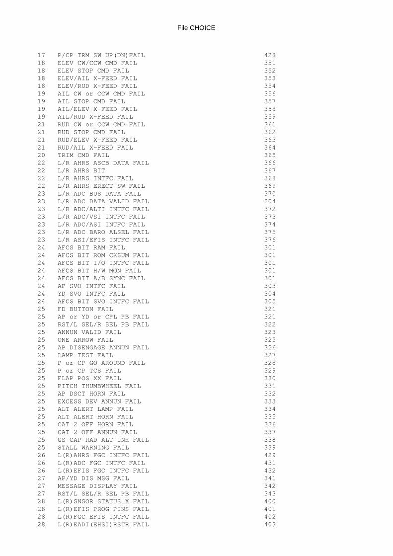
File CHOICE
17 P/CP TRM SW UP(DN)FAIL 42818 ELEV CW/CCW CMD FAIL 35118 ELEV STOP CMD FAIL 35218 ELEV/AIL X-FEED FAIL 35318 ELEV/RUD X-FEED FAIL 35419 AIL CW or CCW CMD FAIL 35619 AIL STOP CMD FAIL 35719 AIL/ELEV X-FEED FAIL 35819 AIL/RUD X-FEED FAIL 35921 RUD CW or CCW CMD FAIL 36121 RUD STOP CMD FAIL 36221 RUD/ELEV X-FEED FAIL 36321 RUD/AIL X-FEED FAIL 36420 TRIM CMD FAIL 36522 L/R AHRS ASCB DATA FAIL 36622 L/R AHRS BIT 36722 L/R AHRS INTFC FAIL 36822 L/R AHRS ERECT SW FAIL 36923 L/R ADC BUS DATA FAIL 37023 L/R ADC DATA VALID FAIL 20423 L/R ADC/ALTI INTFC FAIL 37223 L/R ADC/VSI INTFC FAIL 37323 L/R ADC/ASI INTFC FAIL 37423 L/R ADC BARO ALSEL FAIL 37523 L/R ASI/EFIS INTFC FAIL 37624 AFCS BIT RAM FAIL 30124 AFCS BIT ROM CKSUM FAIL 30124 AFCS BIT I/O INTFC FAIL 30124 AFCS BIT H/W MON FAIL 30124 AFCS BIT A/B SYNC FAIL 30124 AP SVO INTFC FAIL 30324 YD SVO INTFC FAIL 30424 AFCS BIT SVO INTFC FAIL 30525 FD BUTTON FAIL 32125 AP or YD or CPL PB FAIL 32125 RST/L SEL/R SEL PB FAIL 32225 ANNUN VALID FAIL 32325 ONE ARROW FAIL 32525 AP DISENGAGE ANNUN FAIL 32625 LAMP TEST FAIL 32725 P or CP GO AROUND FAIL 32825 P or CP TCS FAIL 32925 FLAP POS XX FAIL 33025 PITCH THUMBWHEEL FAIL 33125 AP DSCT HORN FAIL 33225 EXCESS DEV ANNUN FAIL 33325 ALT ALERT LAMP FAIL 33425 ALT ALERT HORN FAIL 33525 CAT 2 OFF HORN FAIL 33625 CAT 2 OFF ANNUN FAIL 33725 GS CAP RAD ALT INH FAIL 33825 STALL WARNING FAIL 33926 L(R)AHRS FGC INTFC FAIL 42926 L(R)ADC FGC INTFC FAIL 43126 L(R)EFIS FGC INTFC FAIL 43227 AP/YD DIS MSG FAIL 34127 MESSAGE DISPLAY FAIL 34227 RST/L SEL/R SEL PB FAIL 34328 L(R)SNSOR STATUS X FAIL 40028 L(R)EFIS PROG PINS FAIL 40128 L(R)FGC EFIS INTFC FAIL 40228 L(R)EADI(EHSI)RSTR FAIL 403
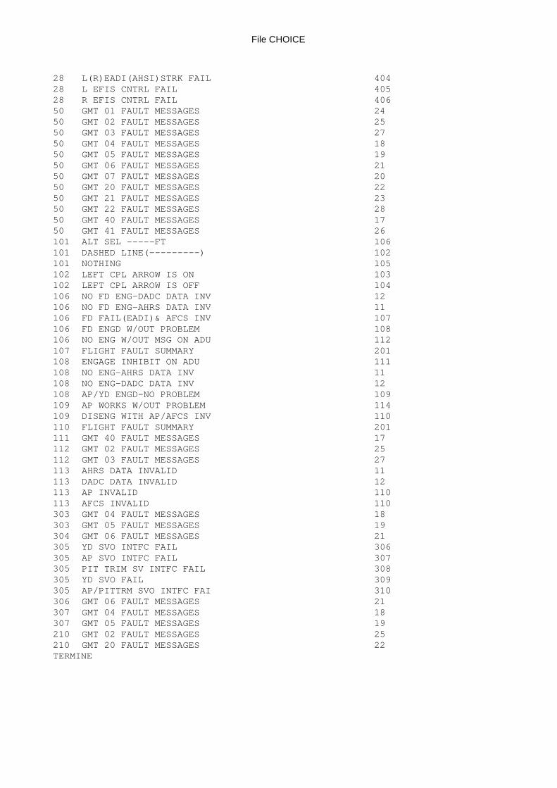
File CHOICE
28 L(R)EADI(AHSI)STRK FAIL 40428 L EFIS CNTRL FAIL 40528 R EFIS CNTRL FAIL 40650 GMT 01 FAULT MESSAGES 2450 GMT 02 FAULT MESSAGES 2550 GMT 03 FAULT MESSAGES 2750 GMT 04 FAULT MESSAGES 1850 GMT 05 FAULT MESSAGES 1950 GMT 06 FAULT MESSAGES 2150 GMT 07 FAULT MESSAGES 2050 GMT 20 FAULT MESSAGES 2250 GMT 21 FAULT MESSAGES 2350 GMT 22 FAULT MESSAGES 2850 GMT 40 FAULT MESSAGES 1750 GMT 41 FAULT MESSAGES 26101 ALT SEL -----FT 106101 DASHED LINE(---------) 102101 NOTHING 105102 LEFT CPL ARROW IS ON 103102 LEFT CPL ARROW IS OFF 104106 NO FD ENG-DADC DATA INV 12106 NO FD ENG-AHRS DATA INV 11106 FD FAIL(EADI)& AFCS INV 107106 FD ENGD W/OUT PROBLEM 108106 NO ENG W/OUT MSG ON ADU 112107 FLIGHT FAULT SUMMARY 201108 ENGAGE INHIBIT ON ADU 111108 NO ENG-AHRS DATA INV 11108 NO ENG-DADC DATA INV 12108 AP/YD ENGD-NO PROBLEM 109109 AP WORKS W/OUT PROBLEM 114109 DISENG WITH AP/AFCS INV 110110 FLIGHT FAULT SUMMARY 201111 GMT 40 FAULT MESSAGES 17112 GMT 02 FAULT MESSAGES 25112 GMT 03 FAULT MESSAGES 27113 AHRS DATA INVALID 11113 DADC DATA INVALID 12113 AP INVALID 110113 AFCS INVALID 110303 GMT 04 FAULT MESSAGES 18303 GMT 05 FAULT MESSAGES 19304 GMT 06 FAULT MESSAGES 21305 YD SVO INTFC FAIL 306305 AP SVO INTFC FAIL 307305 PIT TRIM SV INTFC FAIL 308305 YD SVO FAIL 309305 AP/PITTRM SVO INTFC FAI 310306 GMT 06 FAULT MESSAGES 21307 GMT 04 FAULT MESSAGES 18307 GMT 05 FAULT MESSAGES 19210 GMT 02 FAULT MESSAGES 25210 GMT 20 FAULT MESSAGES 22TERMINE
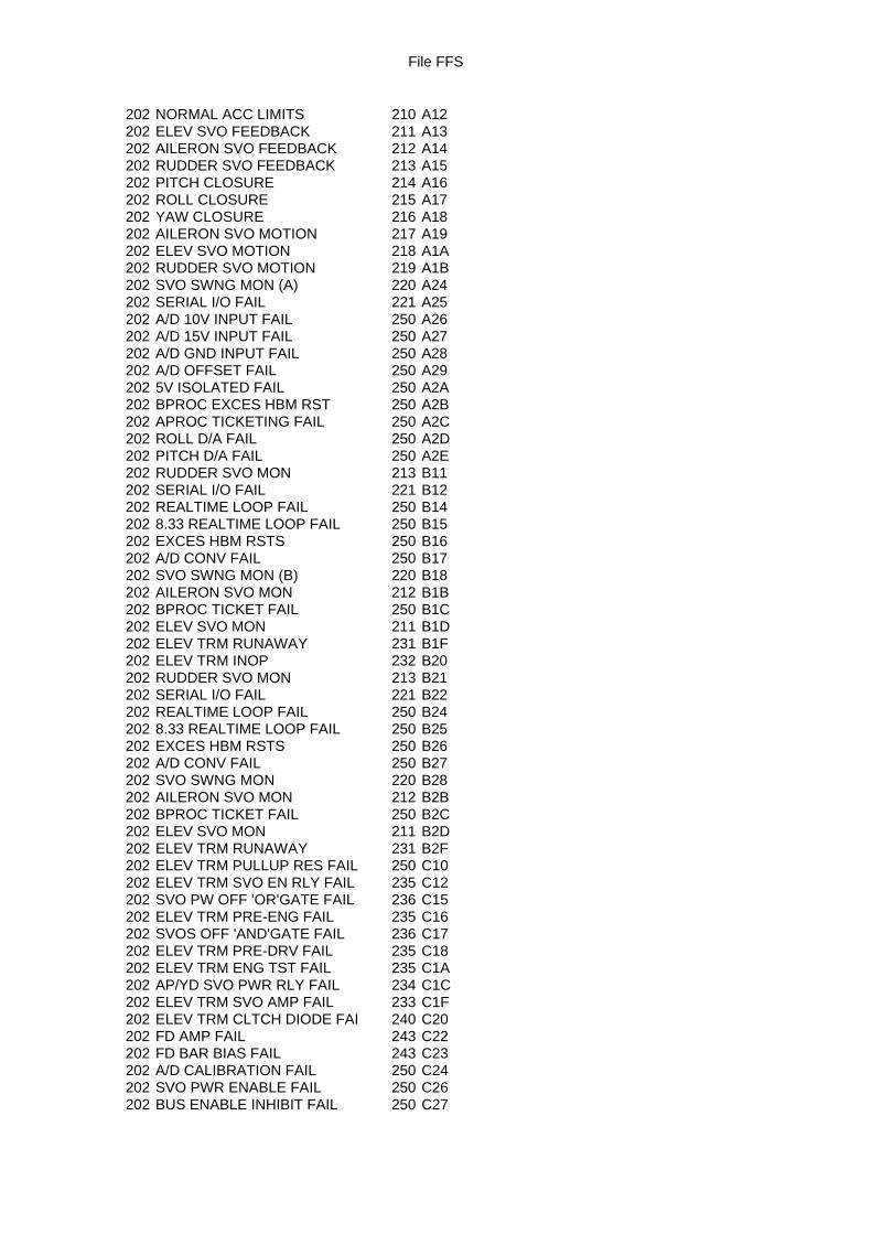
File FFS
202 NORMAL ACC LIMITS 210 A12202 ELEV SVO FEEDBACK 211 A13202 AILERON SVO FEEDBACK 212 A14202 RUDDER SVO FEEDBACK 213 A15202 PITCH CLOSURE 214 A16202 ROLL CLOSURE 215 A17202 YAW CLOSURE 216 A18202 AILERON SVO MOTION 217 A19202 ELEV SVO MOTION 218 A1A202 RUDDER SVO MOTION 219 A1B202 SVO SWNG MON (A) 220 A24202 SERIAL I/O FAIL 221 A25202 A/D 10V INPUT FAIL 250 A26202 A/D 15V INPUT FAIL 250 A27202 A/D GND INPUT FAIL 250 A28202 A/D OFFSET FAIL 250 A29202 5V ISOLATED FAIL 250 A2A202 BPROC EXCES HBM RST 250 A2B202 APROC TICKETING FAIL 250 A2C202 ROLL D/A FAIL 250 A2D202 PITCH D/A FAIL 250 A2E202 RUDDER SVO MON 213 B11202 SERIAL I/O FAIL 221 B12202 REALTIME LOOP FAIL 250 B14202 8.33 REALTIME LOOP FAIL 250 B15202 EXCES HBM RSTS 250 B16202 A/D CONV FAIL 250 B17202 SVO SWNG MON (B) 220 B18202 AILERON SVO MON 212 B1B202 BPROC TICKET FAIL 250 B1C202 ELEV SVO MON 211 B1D202 ELEV TRM RUNAWAY 231 B1F202 ELEV TRM INOP 232 B20202 RUDDER SVO MON 213 B21202 SERIAL I/O FAIL 221 B22202 REALTIME LOOP FAIL 250 B24202 8.33 REALTIME LOOP FAIL 250 B25202 EXCES HBM RSTS 250 B26202 A/D CONV FAIL 250 B27202 SVO SWNG MON 220 B28202 AILERON SVO MON 212 B2B202 BPROC TICKET FAIL 250 B2C202 ELEV SVO MON 211 B2D202 ELEV TRM RUNAWAY 231 B2F202 ELEV TRM PULLUP RES FAIL 250 C10202 ELEV TRM SVO EN RLY FAIL 235 C12202 SVO PW OFF 'OR'GATE FAIL 236 C15202 ELEV TRM PRE-ENG FAIL 235 C16202 SVOS OFF 'AND'GATE FAIL 236 C17202 ELEV TRM PRE-DRV FAIL 235 C18202 ELEV TRM ENG TST FAIL 235 C1A202 AP/YD SVO PWR RLY FAIL 234 C1C202 ELEV TRM SVO AMP FAIL 233 C1F202 ELEV TRM CLTCH DIODE FAI 240 C20202 FD AMP FAIL 243 C22202 FD BAR BIAS FAIL 243 C23202 A/D CALIBRATION FAIL 250 C24202 SVO PWR ENABLE FAIL 250 C26202 BUS ENABLE INHIBIT FAIL 250 C27
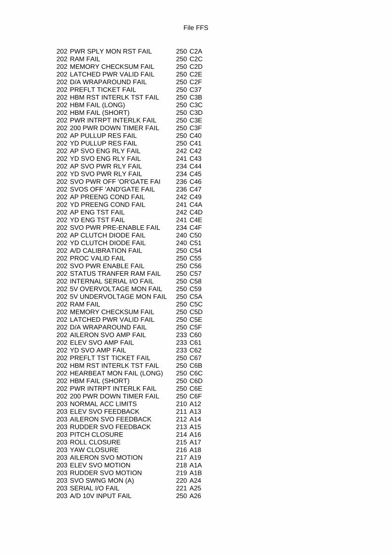
File FFS
202 PWR SPLY MON RST FAIL 250 C2A202 RAM FAIL 250 C2C202 MEMORY CHECKSUM FAIL 250 C2D202 LATCHED PWR VALID FAIL 250 C2E202 D/A WRAPAROUND FAIL 250 C2F202 PREFLT TICKET FAIL 250 C37202 HBM RST INTERLK TST FAIL 250 C3B202 HBM FAIL (LONG) 250 C3C202 HBM FAIL (SHORT) 250 C3D202 PWR INTRPT INTERLK FAIL 250 C3E202 200 PWR DOWN TIMER FAIL 250 C3F202 AP PULLUP RES FAIL 250 C40202 YD PULLUP RES FAIL 250 C41202 AP SVO ENG RLY FAIL 242 C42202 YD SVO ENG RLY FAIL 241 C43202 AP SVO PWR RLY FAIL 234 C44202 YD SVO PWR RLY FAIL 234 C45202 SVO PWR OFF 'OR'GATE FAI 236 C46202 SVOS OFF 'AND'GATE FAIL 236 C47202 AP PREENG COND FAIL 242 C49202 YD PREENG COND FAIL 241 C4A202 AP ENG TST FAIL 242 C4D202 YD ENG TST FAIL 241 C4E202 SVO PWR PRE-ENABLE FAIL 234 C4F202 AP CLUTCH DIODE FAIL 240 C50202 YD CLUTCH DIODE FAIL 240 C51202 A/D CALIBRATION FAIL 250 C54202 PROC VALID FAIL 250 C55202 SVO PWR ENABLE FAIL 250 C56202 STATUS TRANFER RAM FAIL 250 C57202 INTERNAL SERIAL I/O FAIL 250 C58202 5V OVERVOLTAGE MON FAIL 250 C59202 5V UNDERVOLTAGE MON FAIL 250 C5A202 RAM FAIL 250 C5C202 MEMORY CHECKSUM FAIL 250 C5D202 LATCHED PWR VALID FAIL 250 C5E202 D/A WRAPAROUND FAIL 250 C5F202 AILERON SVO AMP FAIL 233 C60202 ELEV SVO AMP FAIL 233 C61202 YD SVO AMP FAIL 233 C62202 PREFLT TST TICKET FAIL 250 C67202 HBM RST INTERLK TST FAIL 250 C6B202 HEARBEAT MON FAIL (LONG) 250 C6C202 HBM FAIL (SHORT) 250 C6D202 PWR INTRPT INTERLK FAIL 250 C6E202 200 PWR DOWN TIMER FAIL 250 C6F203 NORMAL ACC LIMITS 210 A12203 ELEV SVO FEEDBACK 211 A13203 AILERON SVO FEEDBACK 212 A14203 RUDDER SVO FEEDBACK 213 A15203 PITCH CLOSURE 214 A16203 ROLL CLOSURE 215 A17203 YAW CLOSURE 216 A18203 AILERON SVO MOTION 217 A19203 ELEV SVO MOTION 218 A1A203 RUDDER SVO MOTION 219 A1B203 SVO SWNG MON (A) 220 A24203 SERIAL I/O FAIL 221 A25203 A/D 10V INPUT FAIL 250 A26
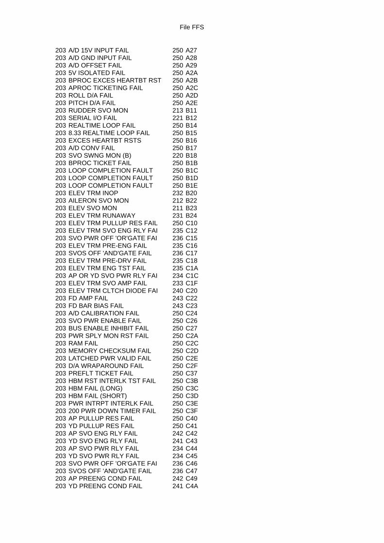
File FFS
203 A/D 15V INPUT FAIL 250 A27203 A/D GND INPUT FAIL 250 A28203 A/D OFFSET FAIL 250 A29203 5V ISOLATED FAIL 250 A2A203 BPROC EXCES HEARTBT RST 250 A2B203 APROC TICKETING FAIL 250 A2C203 ROLL D/A FAIL 250 A2D203 PITCH D/A FAIL 250 A2E203 RUDDER SVO MON 213 B11203 SERIAL I/O FAIL 221 B12203 REALTIME LOOP FAIL 250 B14203 8.33 REALTIME LOOP FAIL 250 B15203 EXCES HEARTBT RSTS 250 B16203 A/D CONV FAIL 250 B17203 SVO SWNG MON (B) 220 B18203 BPROC TICKET FAIL 250 B1B203 LOOP COMPLETION FAULT 250 B1C203 LOOP COMPLETION FAULT 250 B1D203 LOOP COMPLETION FAULT 250 B1E203 ELEV TRM INOP 232 B20203 AILERON SVO MON 212 B22203 ELEV SVO MON 211 B23203 ELEV TRM RUNAWAY 231 B24203 ELEV TRM PULLUP RES FAIL 250 C10203 ELEV TRM SVO ENG RLY FAI 235 C12203 SVO PWR OFF 'OR'GATE FAI 236 C15203 ELEV TRM PRE-ENG FAIL 235 C16203 SVOS OFF 'AND'GATE FAIL 236 C17203 ELEV TRM PRE-DRV FAIL 235 C18203 ELEV TRM ENG TST FAIL 235 C1A203 AP OR YD SVO PWR RLY FAI 234 C1C203 ELEV TRM SVO AMP FAIL 233 C1F203 ELEV TRM CLTCH DIODE FAI 240 C20203 FD AMP FAIL 243 C22203 FD BAR BIAS FAIL 243 C23203 A/D CALIBRATION FAIL 250 C24203 SVO PWR ENABLE FAIL 250 C26203 BUS ENABLE INHIBIT FAIL 250 C27203 PWR SPLY MON RST FAIL 250 C2A203 RAM FAIL 250 C2C203 MEMORY CHECKSUM FAIL 250 C2D203 LATCHED PWR VALID FAIL 250 C2E203 D/A WRAPAROUND FAIL 250 C2F203 PREFLT TICKET FAIL 250 C37203 HBM RST INTERLK TST FAIL 250 C3B203 HBM FAIL (LONG) 250 C3C203 HBM FAIL (SHORT) 250 C3D203 PWR INTRPT INTERLK FAIL 250 C3E203 200 PWR DOWN TIMER FAIL 250 C3F203 AP PULLUP RES FAIL 250 C40203 YD PULLUP RES FAIL 250 C41203 AP SVO ENG RLY FAIL 242 C42203 YD SVO ENG RLY FAIL 241 C43203 AP SVO PWR RLY FAIL 234 C44203 YD SVO PWR RLY FAIL 234 C45203 SVO PWR OFF 'OR'GATE FAI 236 C46203 SVOS OFF 'AND'GATE FAIL 236 C47203 AP PREENG COND FAIL 242 C49203 YD PREENG COND FAIL 241 C4A
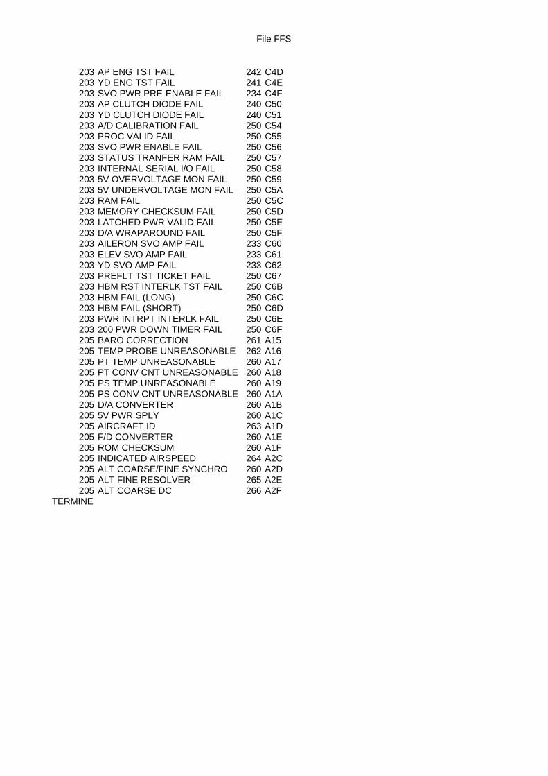
File FFS
203 AP ENG TST FAIL 242 C4D203 YD ENG TST FAIL 241 C4E203 SVO PWR PRE-ENABLE FAIL 234 C4F203 AP CLUTCH DIODE FAIL 240 C50203 YD CLUTCH DIODE FAIL 240 C51203 A/D CALIBRATION FAIL 250 C54203 PROC VALID FAIL 250 C55203 SVO PWR ENABLE FAIL 250 C56203 STATUS TRANFER RAM FAIL 250 C57203 INTERNAL SERIAL I/O FAIL 250 C58203 5V OVERVOLTAGE MON FAIL 250 C59203 5V UNDERVOLTAGE MON FAIL 250 C5A203 RAM FAIL 250 C5C203 MEMORY CHECKSUM FAIL 250 C5D203 LATCHED PWR VALID FAIL 250 C5E203 D/A WRAPAROUND FAIL 250 C5F203 AILERON SVO AMP FAIL 233 C60203 ELEV SVO AMP FAIL 233 C61203 YD SVO AMP FAIL 233 C62203 PREFLT TST TICKET FAIL 250 C67203 HBM RST INTERLK TST FAIL 250 C6B203 HBM FAIL (LONG) 250 C6C203 HBM FAIL (SHORT) 250 C6D203 PWR INTRPT INTERLK FAIL 250 C6E203 200 PWR DOWN TIMER FAIL 250 C6F205 BARO CORRECTION 261 A15205 TEMP PROBE UNREASONABLE 262 A16205 PT TEMP UNREASONABLE 260 A17205 PT CONV CNT UNREASONABLE 260 A18205 PS TEMP UNREASONABLE 260 A19205 PS CONV CNT UNREASONABLE 260 A1A205 D/A CONVERTER 260 A1B205 5V PWR SPLY 260 A1C205 AIRCRAFT ID 263 A1D205 F/D CONVERTER 260 A1E205 ROM CHECKSUM 260 A1F205 INDICATED AIRSPEED 264 A2C205 ALT COARSE/FINE SYNCHRO 260 A2D205 ALT FINE RESOLVER 265 A2E205 ALT COARSE DC 266 A2F
TERMINE
Page 1 sur 10
TCAS MAINTENANCE FUNCTION
SPECIFICATION
REFERENCE DO/TY 3168/04 Ed.01
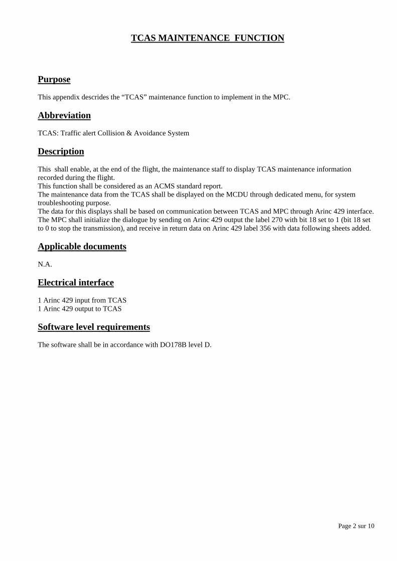
Page 2 sur 10
TCAS MAINTENANCE FUNCTION
Purpose
This appendix descrides the “TCAS” maintenance function to implement in the MPC.
Abbreviation
TCAS: Traffic alert Collision & Avoidance System
Description
This shall enable, at the end of the flight, the maintenance staff to display TCAS maintenance informationrecorded during the flight.This function shall be considered as an ACMS standard report.The maintenance data from the TCAS shall be displayed on the MCDU through dedicated menu, for systemtroubleshooting purpose.The data for this displays shall be based on communication between TCAS and MPC through Arinc 429 interface.The MPC shall initialize the dialogue by sending on Arinc 429 output the label 270 with bit 18 set to 1 (bit 18 setto 0 to stop the transmission), and receive in return data on Arinc 429 label 356 with data following sheets added.
Applicable documents
N.A.
Electrical interface
1 Arinc 429 input from TCAS1 Arinc 429 output to TCAS
Software level requirements
The software shall be in accordance with DO178B level D.
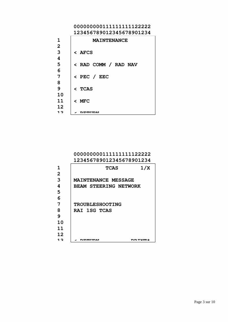
Page 3 sur 10
TCAS 1/X
MAINTENANCE MESSAGEBEAM STEERING NETWORK
TROUBLESHOOTINGRAI 1SG TCAS
< RETURN PRINT*
12345678910111213
000000000111111111122222123456789012345678901234
MAINTENANCE
< AFCS
< RAD COMM / RAD NAV
< PEC / EEC
< TCAS
< MFC
< RETURN
12345678910111213
000000000111111111122222123456789012345678901234
Page 4 sur 10
TCAS 1/X
MAINTENANCE MESSAGERA DISPLAY BUS 2 WRAP A.
TROUBLESHOOTINGWRG 10FL2 VSI-2/1SG TCASRAI 10FL2 VSI-2
12345678910111213
000000000111111111122222123456789012345678901234
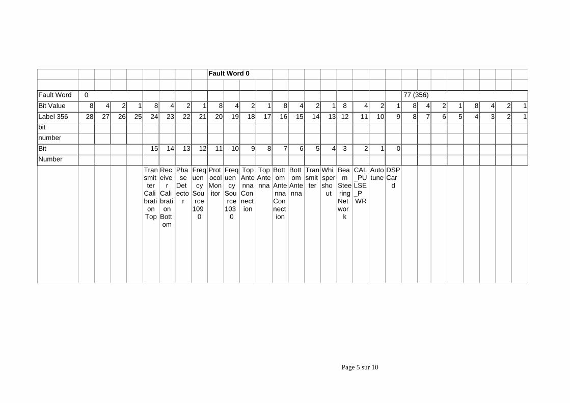
Page 5 sur 10
Fault Word 0
Fault Word 0 77 (356)
Bit Value 8 4 2 1 8 4 2 1 8 4 2 1 8 4 2 1 8 4 2 1 8 4 2 1 8 4 2 1
Label 356 28 27 26 25 24 23 22 21 20 19 18 17 16 15 14 13 12 11 10 9 8 7 6 5 4 3 2 1
bit
number
Bit 15 14 13 12 11 10 9 8 7 6 5 4 3 2 1 0
Number
Transmitter
Calibration
Top
Receive
rCalibration
Bottom
Phase
Detecto
r
Frequency
Source
1090
ProtocolMonitor
Frequency
Source
1030
TopAntennaConnection
TopAntenna
Bottom
AntennaConnection
Bottom
Antenna
Transmitter
Whispersho
ut
Beam
SteeringNetwor
k
CAL_PULSE_PWR
Autotune
DSPCar
d
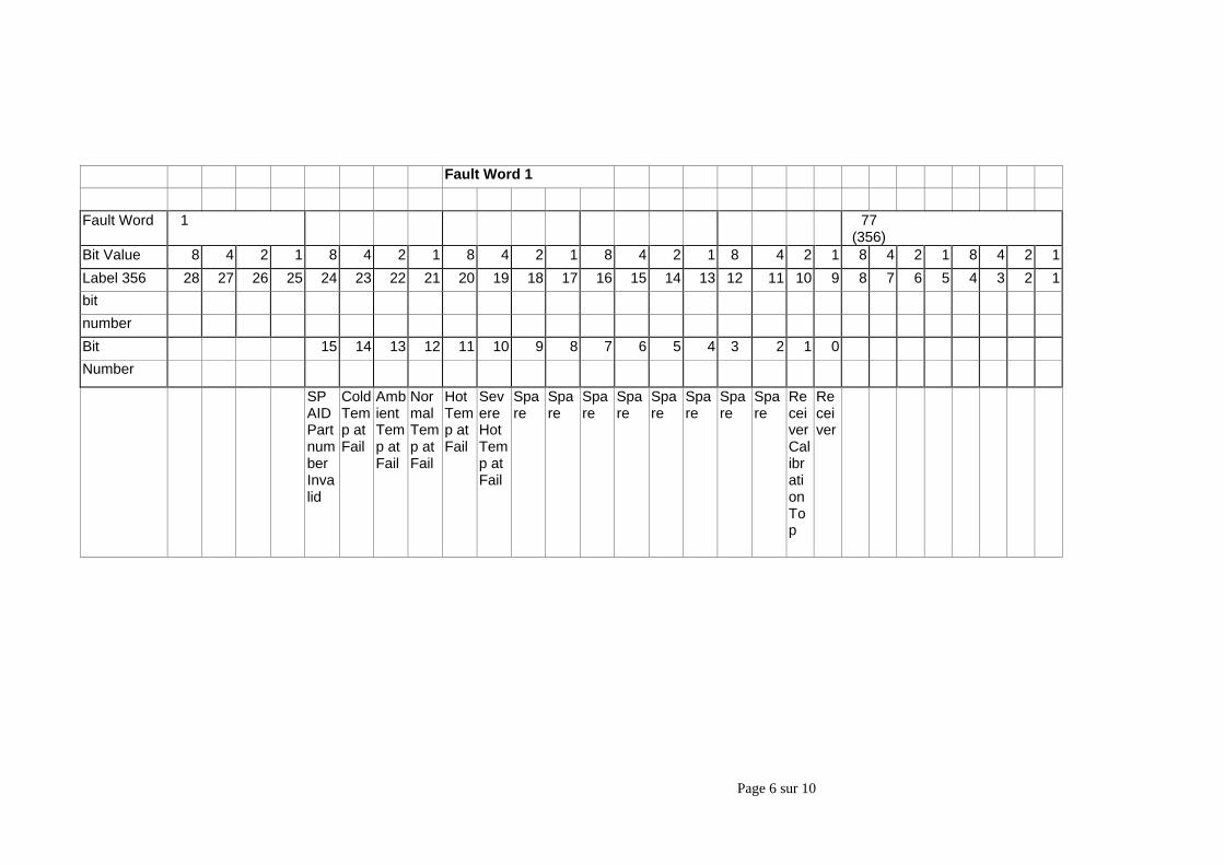
Page 6 sur 10
Fault Word 1
Fault Word 1 77(356)
Bit Value 8 4 2 1 8 4 2 1 8 4 2 1 8 4 2 1 8 4 2 1 8 4 2 1 8 4 2 1
Label 356 28 27 26 25 24 23 22 21 20 19 18 17 16 15 14 13 12 11 10 9 8 7 6 5 4 3 2 1
bit
number
Bit 15 14 13 12 11 10 9 8 7 6 5 4 3 2 1 0
Number
SPAIDPartnumberInvalid
ColdTemp atFail
AmbientTemp atFail
NormalTemp atFail
HotTemp atFail
SevereHotTemp atFail
Spare
Spare
Spare
Spare
Spare
Spare
Spare
Spare
ReceiverCalibrationTop
Receiver
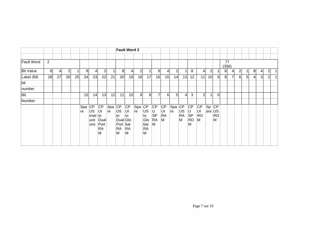
Page 7 sur 10
Fault Word 2
Fault Word 2 77(356)
Bit Value 8 4 2 1 8 4 2 1 8 4 2 1 8 4 2 1 8 4 2 1 8 4 2 1 8 4 2 1
Label 356 28 27 26 25 24 23 22 21 20 19 18 17 16 15 14 13 12 11 10 9 8 7 6 5 4 3 2 1
bit
number
Bit 15 14 13 12 11 10 9 8 7 6 5 4 3 2 1 0
Number
Spare
CPUSInstructions
CPUItoDualPortRAM
Spare
CPUStoDualPortRAM
CPUItoGlobalRAM
Spare
CPUStoGlobalRAM
CPUSPRAM
CPUIRAM
Spare
CPUSRAM
CPUSPROM
CPUIROM
Spare
CPUSROM
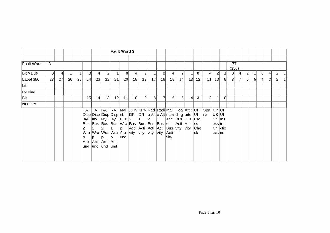
Page 8 sur 10
Fault Word 3
Fault Word 3 77(356)
Bit Value 8 4 2 1 8 4 2 1 8 4 2 1 8 4 2 1 8 4 2 1 8 4 2 1 8 4 2 1
Label 356 28 27 26 25 24 23 22 21 20 19 18 17 16 15 14 13 12 11 10 9 8 7 6 5 4 3 2 1
bit
number
Bit 15 14 13 12 11 10 9 8 7 6 5 4 3 2 1 0
Number
TADisplayBus2WrapAround
TADisplayBus1WrapAround
RADisplayBus2WrapAround
RADisplayBus1WrapAround
Maint.BusWrapAround
XPNDR2BusActivity
XPNDR1BusActivity
Radio Alt2BusActivity
Radio Alt1BusActivity
Maintenance.BusActivity
HeadingBusActivity
AttitudeBusActivity
CPUICrossCheck
Spare
CPUSCrossCheck
CPUIInstructions
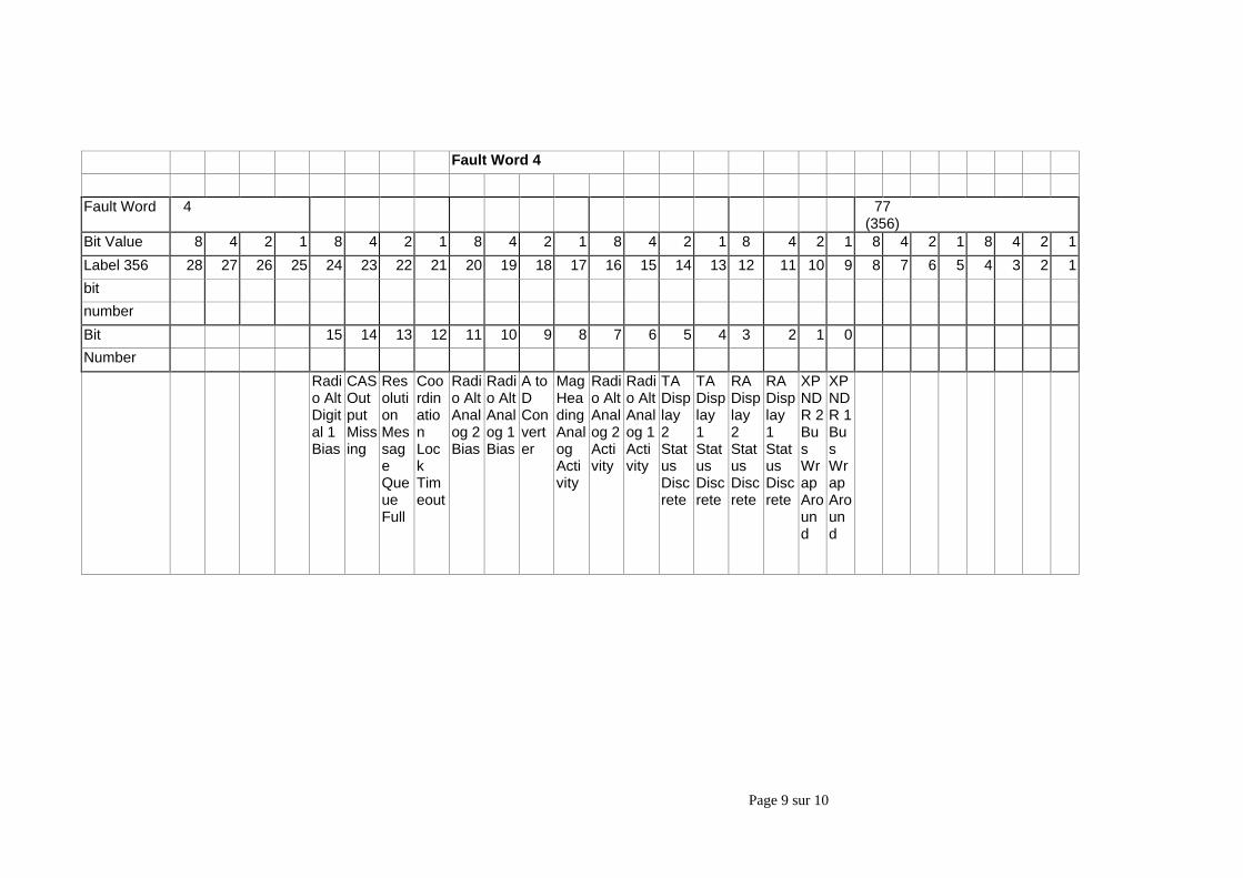
Page 9 sur 10
Fault Word 4
Fault Word 4 77(356)
Bit Value 8 4 2 1 8 4 2 1 8 4 2 1 8 4 2 1 8 4 2 1 8 4 2 1 8 4 2 1
Label 356 28 27 26 25 24 23 22 21 20 19 18 17 16 15 14 13 12 11 10 9 8 7 6 5 4 3 2 1
bit
number
Bit 15 14 13 12 11 10 9 8 7 6 5 4 3 2 1 0
Number
Radio AltDigital 1Bias
CASOutputMissing
ResolutionMessageQueueFull
CoordinationLockTimeout
Radio AltAnalog 2Bias
Radio AltAnalog 1Bias
A toDConverter
MagHeadingAnalogActivity
Radio AltAnalog 2Activity
Radio AltAnalog 1Activity
TADisplay2StatusDiscrete
TADisplay1StatusDiscrete
RADisplay2StatusDiscrete
RADisplay1StatusDiscrete
XPNDR 2BusWrapAround
XPNDR 1BusWrapAround
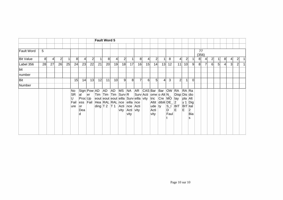
Page 10 sur 10
Fault Word 5
Fault Word 5 77(356)
Bit Value 8 4 2 1 8 4 2 1 8 4 2 1 8 4 2 1 8 4 2 1 8 4 2 1 8 4 2 1
Label 356 28 27 26 25 24 23 22 21 20 19 18 17 16 15 14 13 12 11 10 9 8 7 6 5 4 3 2 1
bit
number
Bit 15 14 13 12 11 10 9 8 7 6 5 4 3 2 1 0
Number
NoSRUFailure
SignalProcessorDead
PowerUpFail
ADTimeoutHeading
ADTimeoutRALT 2
ADTimeoutRALT 1
MSSurveillanceActivity
NARSurveillanceActivity
ARSurveillanceActivity
CASActivity
BarometricAltitudeActivity
Baro AltCredibility
OWN_MODE_S_IDFault
RADisplay2BITE
RADisplay 1BITE
RadioAltDigital2Bias
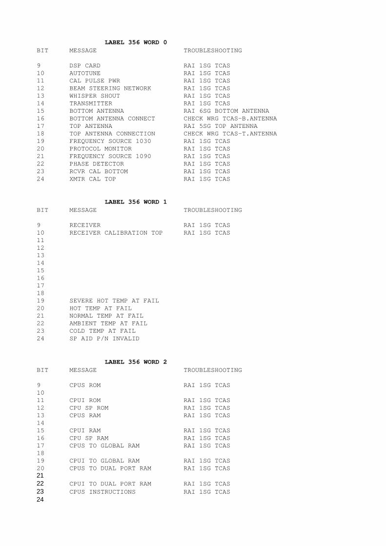
LABEL 356 WORD 0BIT MESSAGE TROUBLESHOOTING
9 DSP CARD RAI 1SG TCAS10 AUTOTUNE RAI 1SG TCAS11 CAL PULSE PWR RAI 1SG TCAS12 BEAM STEERING NETWORK RAI 1SG TCAS13 WHISPER SHOUT RAI 1SG TCAS14 TRANSMITTER RAI 1SG TCAS15 BOTTOM ANTENNA RAI 6SG BOTTOM ANTENNA16 BOTTOM ANTENNA CONNECT CHECK WRG TCAS-B.ANTENNA17 TOP ANTENNA RAI 5SG TOP ANTENNA18 TOP ANTENNA CONNECTION CHECK WRG TCAS-T.ANTENNA19 FREQUENCY SOURCE 1030 RAI 1SG TCAS20 PROTOCOL MONITOR RAI 1SG TCAS21 FREQUENCY SOURCE 1090 RAI 1SG TCAS22 PHASE DETECTOR RAI 1SG TCAS23 RCVR CAL BOTTOM RAI 1SG TCAS24 XMTR CAL TOP RAI 1SG TCAS
LABEL 356 WORD 1BIT MESSAGE TROUBLESHOOTING
9 RECEIVER RAI 1SG TCAS10 RECEIVER CALIBRATION TOP RAI 1SG TCAS111213141516171819 SEVERE HOT TEMP AT FAIL20 HOT TEMP AT FAIL21 NORMAL TEMP AT FAIL22 AMBIENT TEMP AT FAIL23 COLD TEMP AT FAIL24 SP AID P/N INVALID
LABEL 356 WORD 2BIT MESSAGE TROUBLESHOOTING
9 CPUS ROM RAI 1SG TCAS1011 CPUI ROM RAI 1SG TCAS12 CPU SP ROM RAI 1SG TCAS13 CPUS RAM RAI 1SG TCAS1415 CPUI RAM RAI 1SG TCAS16 CPU SP RAM RAI 1SG TCAS17 CPUS TO GLOBAL RAM RAI 1SG TCAS1819 CPUI TO GLOBAL RAM RAI 1SG TCAS20 CPUS TO DUAL PORT RAM RAI 1SG TCAS2122 CPUI TO DUAL PORT RAM RAI 1SG TCAS23 CPUS INSTRUCTIONS RAI 1SG TCAS24
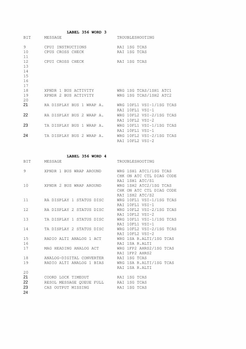
LABEL 356 WORD 3BIT MESSAGE TROUBLESHOOTING
9 CPUI INSTRUCTIONS RAI 1SG TCAS10 CPUS CROSS CHECK RAI 1SG TCAS1112 CPUI CROSS CHECK RAI 1SG TCAS131415161718 XPNDR 1 BUS ACTIVITY WRG 1SG TCAS/1SH1 ATC119 XPNDR 2 BUS ACTIVITY WRG 1SG TCAS/1SH2 ATC22021 RA DISPLAY BUS 1 WRAP A. WRG 10FL1 VSI-1/1SG TCAS
RAI 10FL1 VSI-122 RA DISPLAY BUS 2 WRAP A. WRG 10FL2 VSI-2/1SG TCAS
RAI 10FL2 VSI-223 TA DISPLAY BUS 1 WRAP A. WRG 10FL1 VSI-1/1SG TCAS
RAI 10FL1 VSI-124 TA DISPLAY BUS 2 WRAP A. WRG 10FL2 VSI-2/1SG TCAS
RAI 10FL2 VSI-2
LABEL 356 WORD 4BIT MESSAGE TROUBLESHOOTING
9 XPNDR 1 BUS WRAP AROUND WRG 1SH1 ATC1/1SG TCASCHK ON ATC CTL DIAG CODERAI 1SH1 ATC/S1
10 XPNDR 2 BUS WRAP AROUND WRG 1SH2 ATC2/1SG TCASCHK ON ATC CTL DIAG CODERAI 1SH2 ATC/S2
11 RA DISPLAY 1 STATUS DISC WRG 10FL1 VSI-1/1SG TCASRAI 10FL1 VSI-1
12 RA DISPLAY 2 STATUS DISC WRG 10FL2 VSI-2/1SG TCASRAI 10FL2 VSI-2
13 TA DISPLAY 1 STATUS DISC WRG 10FL1 VSI-1/1SG TCASRAI 10FL1 VSI-1
14 TA DISPLAY 2 STATUS DISC WRG 10FL2 VSI-2/1SG TCASRAI 10FL2 VSI-2
15 RADIO ALTI ANALOG 1 ACT WRG 1SA R.ALTI/1SG TCAS16 RAI 1SA R.ALTI17 MAG HEADING ANALOG ACT WRG 1FP2 AHRS2/1SG TCAS
RAI 1FP2 AHRS218 ANALOG-DIGITAL CONVERTER RAI 1SG TCAS19 RADIO ALTI ANALOG 1 BIAS WRG 1SA R.ALTI/1SG TCAS
RAI 1SA R.ALTI2021 COORD LOCK TIMEOUT RAI 1SG TCAS22 RESOL MESSAGE QUEUE FULL RAI 1SG TCAS23 CAS OUTPUT MISSING RAI 1SG TCAS24
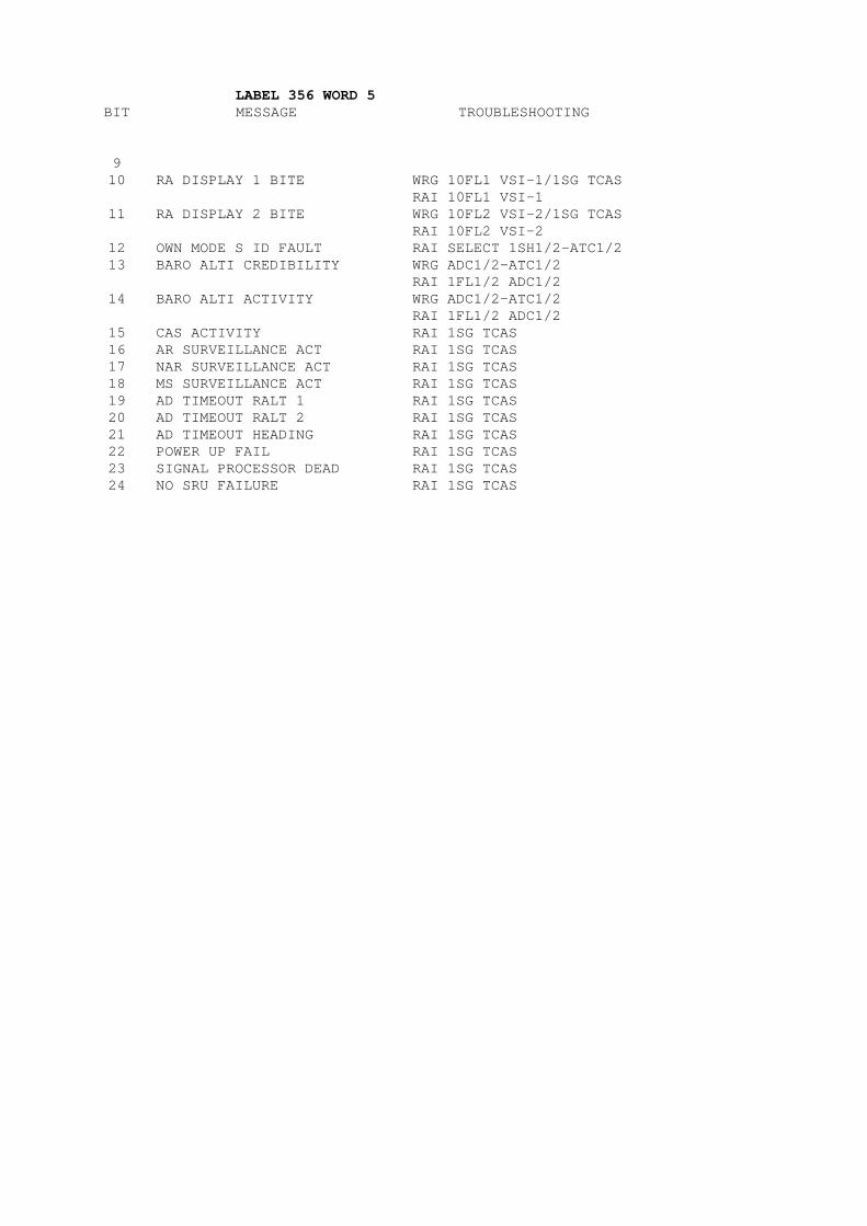
LABEL 356 WORD 5BIT MESSAGE TROUBLESHOOTING
910 RA DISPLAY 1 BITE WRG 10FL1 VSI-1/1SG TCAS
RAI 10FL1 VSI-111 RA DISPLAY 2 BITE WRG 10FL2 VSI-2/1SG TCAS
RAI 10FL2 VSI-212 OWN MODE S ID FAULT RAI SELECT 1SH1/2-ATC1/213 BARO ALTI CREDIBILITY WRG ADC1/2-ATC1/2
RAI 1FL1/2 ADC1/214 BARO ALTI ACTIVITY WRG ADC1/2-ATC1/2
RAI 1FL1/2 ADC1/215 CAS ACTIVITY RAI 1SG TCAS16 AR SURVEILLANCE ACT RAI 1SG TCAS17 NAR SURVEILLANCE ACT RAI 1SG TCAS18 MS SURVEILLANCE ACT RAI 1SG TCAS19 AD TIMEOUT RALT 1 RAI 1SG TCAS20 AD TIMEOUT RALT 2 RAI 1SG TCAS21 AD TIMEOUT HEADING RAI 1SG TCAS22 POWER UP FAIL RAI 1SG TCAS23 SIGNAL PROCESSOR DEAD RAI 1SG TCAS24 NO SRU FAILURE RAI 1SG TCAS
Page 1 sur 12
MFC MAINTENANCE MEMORY READINGFUNCTION
REFERENCE DO/TY 3169/04
Page 2 sur 12
PurposeThis annex describes maintenance code reading inside the Multifunction Computer.
Tasks to be performed are:- reading maintenance codes,- presenting the codes in plain text,- erasing the maintenance memory.
AbbreviationsFIFO First In First OutFFM Flight Fault MemoryMCDU Multifunction Control and Display UnitMFC MultiFunction ComputerWOW Weight On Wheel
DescriptionDescription of MFC maintenance memory:MFC concentrates maintenance codes from peripheral aircraft systems in a maintenance memory.This maintenance memory is divided in two areas (ref figure 1):
• The first area called "Basic Memory":It is divided into 10 systems, each system being able to record 14 different failure codes.When failures occur in the same system, they will be stored following the chronological order.Each failure is stored only once, even if the failure has been encountered several times,
• The second area called "Flight Fault Memory":It is divided into 9 parts corresponding to the last 9 flights and is able to store the failures of the 10 systems.Failures occuring during the first flight are stored in the first part,failures occuring during the second flight are stored in the second part,and so on.At the 10th flight, codes are written in the older memory area (FIFO principle).
MFC memory areas are at the following addresses:
Basic memory :
Memory addresses sys 1 : 4100 … 410F sys 2 : 4110 … 411F sys 3 : 4120 … 412F sys 4 : 4130 … 413F sys 5 : 4140 … 414F sys 6 : 4150 … 415F sys 7 : 4160 … 416F sys 8 : 4170 … 417F sys 9 : 4180 … 418F sys10 : 4190 … 419F
Flight fault memory :Implementation is identical from address 41B0 to 474F dispatched in 9 blocs:
Memory addresses bloc 1 : 41B0 … 424F
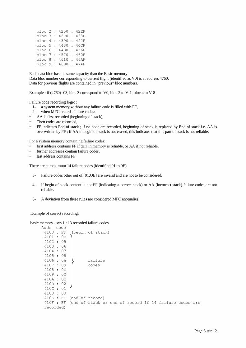
Page 3 sur 12
bloc 2 : 4250 … 42EF bloc 3 : 42F0 … 438F bloc 4 : 4390 … 442F bloc 5 : 4430 … 44CF bloc 6 : 44D0 … 456F bloc 7 : 4570 … 460F bloc 8 : 4610 … 46AF bloc 9 : 46B0 … 474F
Each data bloc has the same capacity than the Basic memory.Data bloc number corresponding to current flight (identified as V0) is at address 4760.Data for previous flights are contained in “previous” bloc numbers.
Example : if (4760)=03, bloc 3 correspond to V0, bloc 2 to V-1, bloc 4 to V-8
Failure code recording logic :1- a system memory without any failure code is filled with FF,2- when MFC records failure codes:
• AA is first recorded (beginning of stack),• Then codes are recorded,• FF indicates End of stack ; if no code are recorded, beginning of stack is replaced by End of stack i.e. AA is
overwritten by FF ; if AA in begin of stack is not erased, this indicates that this part of stack is not reliable.
For a system memory containing failure codes:• first address contains FF if data in memory is reliable, or AA if not reliable,• further addresses contain failure codes,• last address contains FF
There are at maximum 14 failure codes (identified 01 to 0E)
3- Failure codes other out of [01;OE] are invalid and are not to be considered.
4- If begin of stack content is not FF (indicating a correct stack) or AA (incorrect stack) failure codes are notreliable.
5- A deviation from these rules are considered MFC anomalies
Example of correct recording:
basic memory - sys 1 : 13 recorded failure codes Addr code
4100 : FF (begin of stack)4101 : 0B4102 : 054103 : 064104 : 074105 : 084106 : 0A failure4107 : 09 codes4108 : 0C4109 : 0D410A : 0E410B : 02410C : 01410D : 03410E : FF (end of record)410F : FF (end of stack or end of record if 14 failure codes arerecorded)
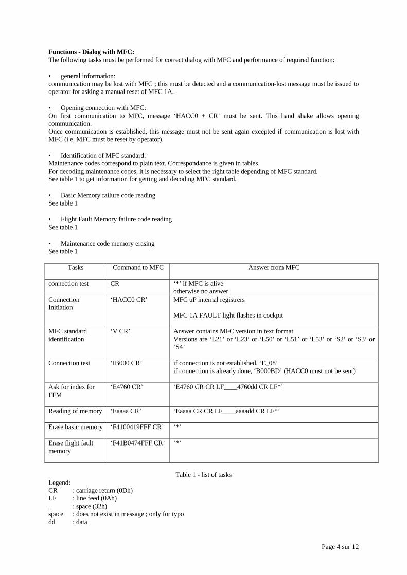
Page 4 sur 12
Functions - Dialog with MFC:The following tasks must be performed for correct dialog with MFC and performance of required function:
• general information:communication may be lost with MFC ; this must be detected and a communication-lost message must be issued tooperator for asking a manual reset of MFC 1A.
• Opening connection with MFC:On first communication to MFC, message ‘HACC0 + CR’ must be sent. This hand shake allows openingcommunication.Once communication is established, this message must not be sent again excepted if communication is lost withMFC (i.e. MFC must be reset by operator).
• Identification of MFC standard:Maintenance codes correspond to plain text. Correspondance is given in tables.For decoding maintenance codes, it is necessary to select the right table depending of MFC standard.See table 1 to get information for getting and decoding MFC standard.
• Basic Memory failure code readingSee table 1
• Flight Fault Memory failure code readingSee table 1
• Maintenance code memory erasingSee table 1
Tasks Command to MFC Answer from MFC
connection test CR ‘*’ if MFC is aliveotherwise no answer
ConnectionInitiation
‘HACC0 CR’ MFC uP internal registrers
MFC 1A FAULT light flashes in cockpit
MFC standardidentification
‘V CR’ Answer contains MFC version in text formatVersions are ‘L21’ or ‘L23’ or ‘L50’ or ‘L51’ or ‘L53’ or ‘S2’ or ‘S3’ or‘S4’
Connection test ‘IB000 CR’ if connection is not established, ‘E_08’if connection is already done, ‘B000BD’ (HACC0 must not be sent)
Ask for index forFFM
‘E4760 CR’ ‘E4760 CR CR LF____4760dd CR LF*’
Reading of memory ‘Eaaaa CR’ ‘Eaaaa CR CR LF____aaaadd CR LF*’
Erase basic memory ‘F4100419FFF CR’ ‘*’
Erase flight faultmemory
‘F41B0474FFF CR’ ‘*’
Table 1 - list of tasksLegend:CR : carriage return (0Dh)LF : line feed (0Ah)_ : space (32h)space : does not exist in message ; only for typodd : data
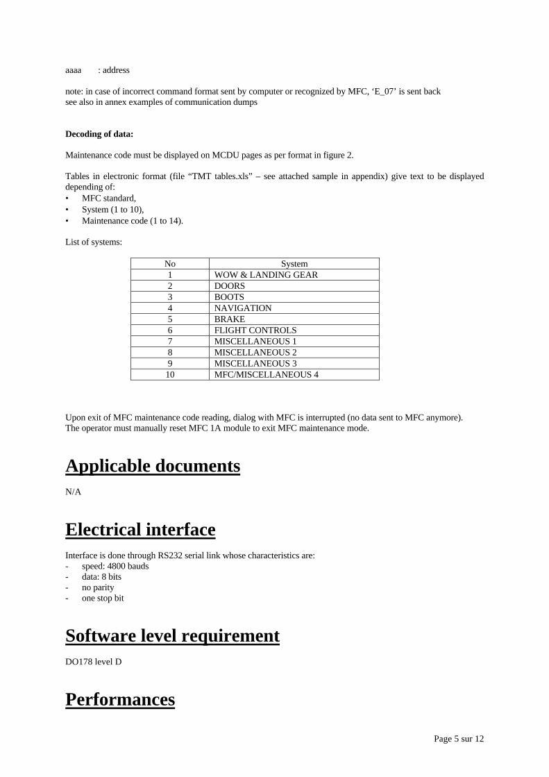
Page 5 sur 12
aaaa : address
note: in case of incorrect command format sent by computer or recognized by MFC, ‘E_07’ is sent backsee also in annex examples of communication dumps
Decoding of data:
Maintenance code must be displayed on MCDU pages as per format in figure 2.
Tables in electronic format (file “TMT tables.xls” – see attached sample in appendix) give text to be displayeddepending of:• MFC standard,• System (1 to 10),• Maintenance code (1 to 14).
List of systems:
No System1 WOW & LANDING GEAR2 DOORS3 BOOTS4 NAVIGATION5 BRAKE6 FLIGHT CONTROLS7 MISCELLANEOUS 18 MISCELLANEOUS 29 MISCELLANEOUS 3
10 MFC/MISCELLANEOUS 4
Upon exit of MFC maintenance code reading, dialog with MFC is interrupted (no data sent to MFC anymore).The operator must manually reset MFC 1A module to exit MFC maintenance mode.
Applicable documentsN/A
Electrical interfaceInterface is done through RS232 serial link whose characteristics are:- speed: 4800 bauds- data: 8 bits- no parity- one stop bit
Software level requirementDO178 level D
Performances

Page 6 sur 12

Page 7 sur 12
Appendix
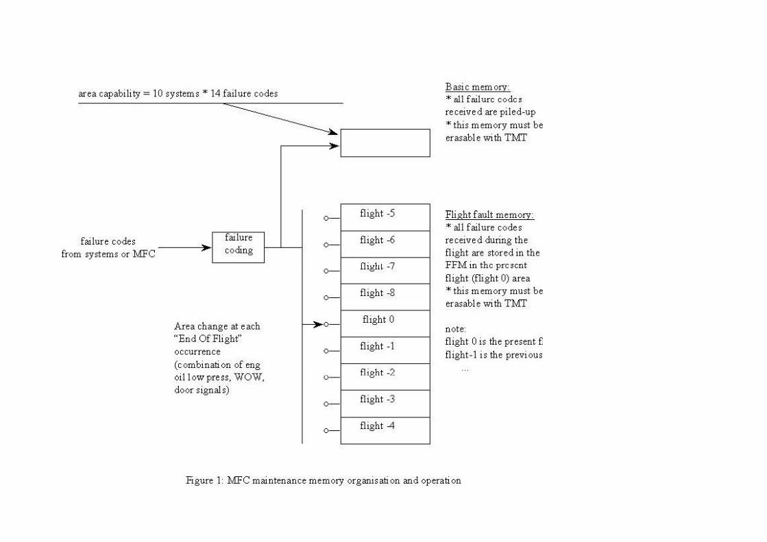
Page 8 sur 12
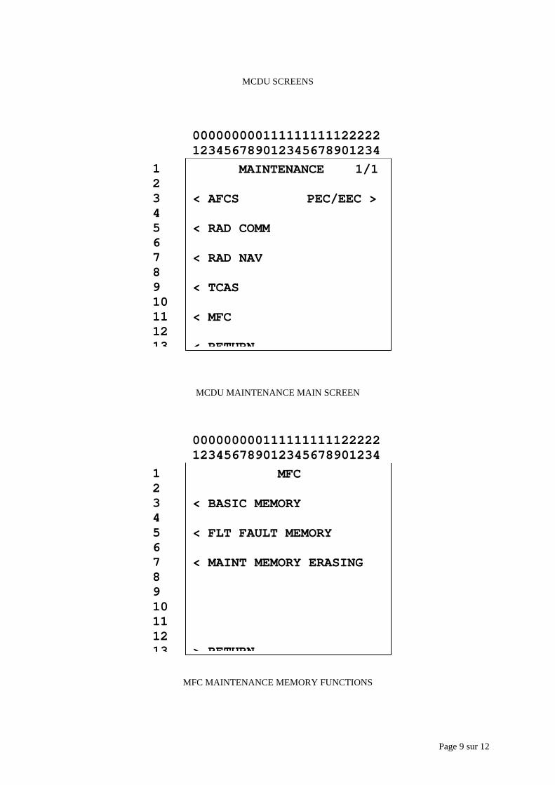
Page 9 sur 12
MCDU SCREENS
MCDU MAINTENANCE MAIN SCREEN
MFC MAINTENANCE MEMORY FUNCTIONS
MAINTENANCE 1/1
< AFCS PEC/EEC >
< RAD COMM
< RAD NAV
< TCAS
< MFC
< RETURN
12345678910111213
000000000111111111122222123456789012345678901234
MFC
< BASIC MEMORY
< FLT FAULT MEMORY
< MAINT MEMORY ERASING
> RETURN
12345678910111213
000000000111111111122222123456789012345678901234
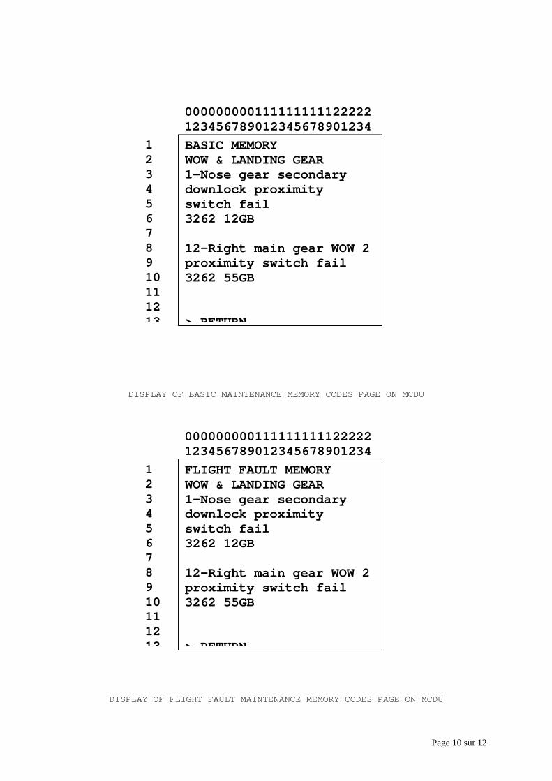
Page 10 sur 12
DISPLAY OF BASIC MAINTENANCE MEMORY CODES PAGE ON MCDU
DISPLAY OF FLIGHT FAULT MAINTENANCE MEMORY CODES PAGE ON MCDU
BASIC MEMORYWOW & LANDING GEAR1-Nose gear secondarydownlock proximityswitch fail3262 12GB
12-Right main gear WOW 2proximity switch fail3262 55GB
> RETURN
12345678910111213
000000000111111111122222123456789012345678901234
FLIGHT FAULT MEMORYWOW & LANDING GEAR1-Nose gear secondarydownlock proximityswitch fail3262 12GB
12-Right main gear WOW 2proximity switch fail3262 55GB
> RETURN
12345678910111213
000000000111111111122222123456789012345678901234
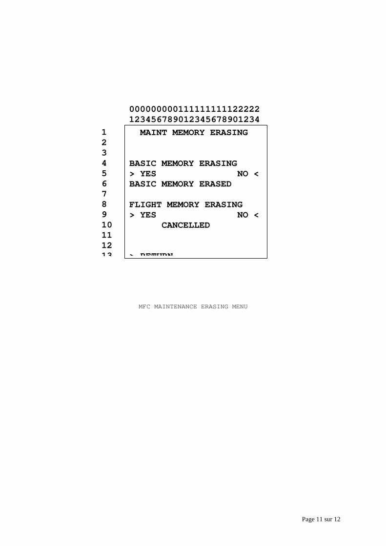
Page 11 sur 12
MFC MAINTENANCE ERASING MENU
MAINT MEMORY ERASING
BASIC MEMORY ERASING> YES NO <BASIC MEMORY ERASED
FLIGHT MEMORY ERASING> YES NO < CANCELLED
> RETURN
12345678910111213
000000000111111111122222123456789012345678901234
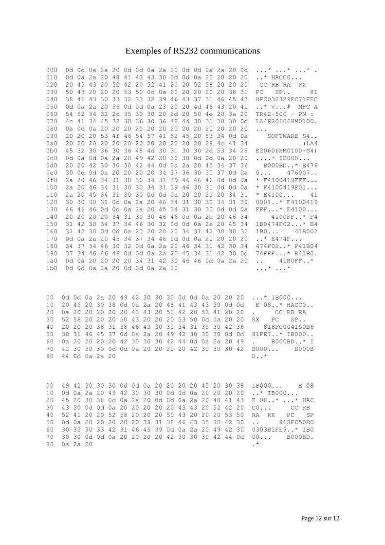
Page 12 sur 12
Exemples of RS232 communications
000 0d 0d 0a 2a 20 0d 0d 0a 2a 20 0d 0d 0a 2a 20 0d ...* ...* ...* .010 0d 0a 2a 20 48 41 43 43 30 0d 0d 0a 20 20 20 20 ..* HACC0...020 20 43 43 20 52 42 20 52 41 20 20 52 58 20 20 20 CC RB RA RX030 50 43 20 20 20 53 50 0d 0a 20 20 20 20 20 38 31 PC SP.. 81040 38 46 43 30 33 32 33 32 39 46 43 37 31 46 45 43 8FC032329FC71FEC050 0d 0a 2a 20 56 0d 0d 0a 23 20 20 4d 46 43 20 41 ..* V...# MFC A060 54 52 34 32 2d 35 30 30 20 2d 20 50 4e 20 3a 20 TR42-500 - PN :070 4c 41 34 45 32 30 36 30 36 48 4d 30 31 30 30 0d LA4E20606HM0100.080 0a 0d 0a 20 20 20 20 20 20 20 20 20 20 20 20 20 ...090 20 20 20 53 4f 46 54 57 41 52 45 20 53 34 0d 0a SOFTWARE S4..0a0 20 20 20 20 20 20 20 20 20 20 20 20 28 4c 41 34 (LA40b0 45 32 30 36 30 36 48 4d 30 31 30 30 2d 53 34 29 E20606HM0100-S4)0c0 0d 0a 0d 0a 2a 20 49 42 30 30 30 0d 0d 0a 20 20 ....* IB000...0d0 20 20 42 30 30 30 42 44 0d 0a 2a 20 45 34 37 36 B000BD..* E4760e0 30 0d 0d 0a 20 20 20 20 34 37 36 30 30 37 0d 0a 0... 476007..0f0 2a 20 46 34 31 30 30 34 31 39 46 46 46 0d 0d 0a * F4100419FFF...100 2a 20 46 34 31 30 30 34 31 39 46 30 31 0d 0d 0a * F4100419F01...110 2a 20 45 34 31 30 30 0d 0d 0a 20 20 20 20 34 31 * E4100... 41120 30 30 30 31 0d 0a 2a 20 46 34 31 30 30 34 31 39 0001..* F4100419130 46 46 46 0d 0d 0a 2a 20 45 34 31 30 30 0d 0d 0a FFF...* E4100...140 20 20 20 20 34 31 30 30 46 46 0d 0a 2a 20 46 34 4100FF..* F4150 31 42 30 34 37 34 46 30 32 0d 0d 0a 2a 20 45 34 1B0474F02...* E4160 31 42 30 0d 0d 0a 20 20 20 20 34 31 42 30 30 32 1B0... 41B002170 0d 0a 2a 20 45 34 37 34 46 0d 0d 0a 20 20 20 20 ..* E474F...180 34 37 34 46 30 32 0d 0a 2a 20 46 34 31 42 30 34 474F02..* F41B04190 37 34 46 46 46 0d 0d 0a 2a 20 45 34 31 42 30 0d 74FFF...* E41B0.1a0 0d 0a 20 20 20 20 34 31 42 30 46 46 0d 0a 2a 20 .. 41B0FF..*1b0 0d 0d 0a 2a 20 0d 0d 0a 2a 20 ...* ...*
00 0d 0d 0a 2a 20 49 42 30 30 30 0d 0d 0a 20 20 20 ...* IB000...10 20 45 20 30 38 0d 0a 2a 20 48 41 43 43 30 0d 0d E 08..* HACC0..20 0a 20 20 20 20 20 43 43 20 52 42 20 52 41 20 20 . CC RB RA30 52 58 20 20 20 50 43 20 20 20 53 50 0d 0a 20 20 RX PC SP..40 20 20 20 38 31 38 46 43 30 30 34 31 35 30 42 36 818FC004150B650 38 31 46 45 37 0d 0a 2a 20 49 42 30 30 30 0d 0d 81FE7..* IB000..60 0a 20 20 20 20 42 30 30 30 42 44 0d 0a 2a 20 49 . B000BD..* I70 42 30 30 30 0d 0d 0a 20 20 20 20 42 30 30 30 42 B000... B000B80 44 0d 0a 2a 20 D..*
00 49 42 30 30 30 0d 0d 0a 20 20 20 20 45 20 30 38 IB000... E 0810 0d 0a 2a 20 49 42 30 30 30 0d 0d 0a 20 20 20 20 ..* IB000...20 45 20 30 38 0d 0a 2a 20 0d 0d 0a 2a 20 48 41 43 E 08..* ...* HAC30 43 30 0d 0d 0a 20 20 20 20 20 43 43 20 52 42 20 C0... CC RB40 52 41 20 20 52 58 20 20 20 50 43 20 20 20 53 50 RA RX PC SP50 0d 0a 20 20 20 20 20 38 31 38 46 43 35 30 42 30 .. 818FC50B060 30 33 30 33 42 31 46 45 39 0d 0a 2a 20 49 42 30 0303B1FE9..* IB070 30 30 0d 0d 0a 20 20 20 20 42 30 30 30 42 44 0d 00... B000BD.80 0a 2a 20 .*
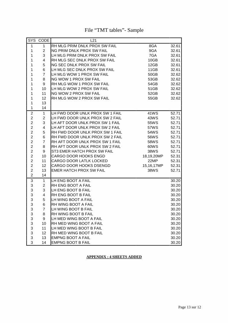
Page 13 sur 12
File “TMT tables”- Sample
SYS CODE L211 1 RH MLG PRIM DNLK PROX SW FAIL 8GA 32.611 2 NG PRIM DNLK PROX SW FAIL 9GA 32.611 3 LH MLG PRIM DNLK PROX SW FAIL 7GA 32.611 4 RH MLG SEC DNLK PROX SW FAIL 10GB 32.611 5 NG SEC DNLK PROX SW FAIL 12GB 32.611 6 LH MLG SEC DNLK PROX SW FAIL 11GB 32.611 7 LH MLG WOW 1 PROX SW FAIL 50GB 32.621 8 NG WOW 1 PROX SW FAIL 53GB 32.621 9 RH MLG WOW 1 PROX SW FAIL 54GB 32.621 10 LH MLG WOW 2 PROX SW FAIL 51GB 32.621 11 NG WOW 2 PROX SW FAIL 52GB 32.621 12 RH MLG WOW 2 PROX SW FAIL 55GB 32.621 131 142 1 LH FWD DOOR UNLK PROX SW 1 FAIL 41WS 52.712 2 LH FWD DOOR UNLK PROX SW 2 FAIL 43WS 52.712 3 LH AFT DOOR UNLK PROX SW 1 FAIL 55WS 52.712 4 LH AFT DOOR UNLK PROX SW 2 FAIL 57WS 52.712 5 RH FWD DOOR UNLK PROX SW 1 FAIL 54WS 52.712 6 RH FWD DOOR UNLK PROX SW 2 FAIL 56WS 52.712 7 RH AFT DOOR UNLK PROX SW 1 FAIL 58WS 52.712 8 RH AFT DOOR UNLK PROX SW 2 FAIL 60WS 52.712 9 ST3 EMER HATCH PROX SW FAIL 38WS 52.712 10 CARGO DOOR HOOKS ENGD 18,19,20MP 52.312 11 CARGO DOOR LATLK LOCKED 22MP 52.312 12 CARGO DOOR HOOKS DSENGD 15,16,17MP 52.312 13 EMER HATCH PROX SW FAIL 38WS 52.712 143 1 LH ENG BOOT A FAIL 30.203 2 RH ENG BOOT A FAIL 30.203 3 LH ENG BOOT B FAIL 30.203 4 RH ENG BOOT B FAIL 30.203 5 LH WING BOOT A FAIL 30.203 6 RH WING BOOT A FAIL 30.203 7 LH WING BOOT B FAIL 30.203 8 RH WING BOOT B FAIL 30.203 9 LH MED WING BOOT A FAIL 30.203 10 RH MED WING BOOT A FAIL 30.203 11 LH MED WING BOOT B FAIL 30.203 12 RH MED WING BOOT B FAIL 30.203 13 EMPNG BOOT A FAIL 30.203 14 EMPNG BOOT B FAIL 30.20
APPENDIX : 4 SHEETS ADDED
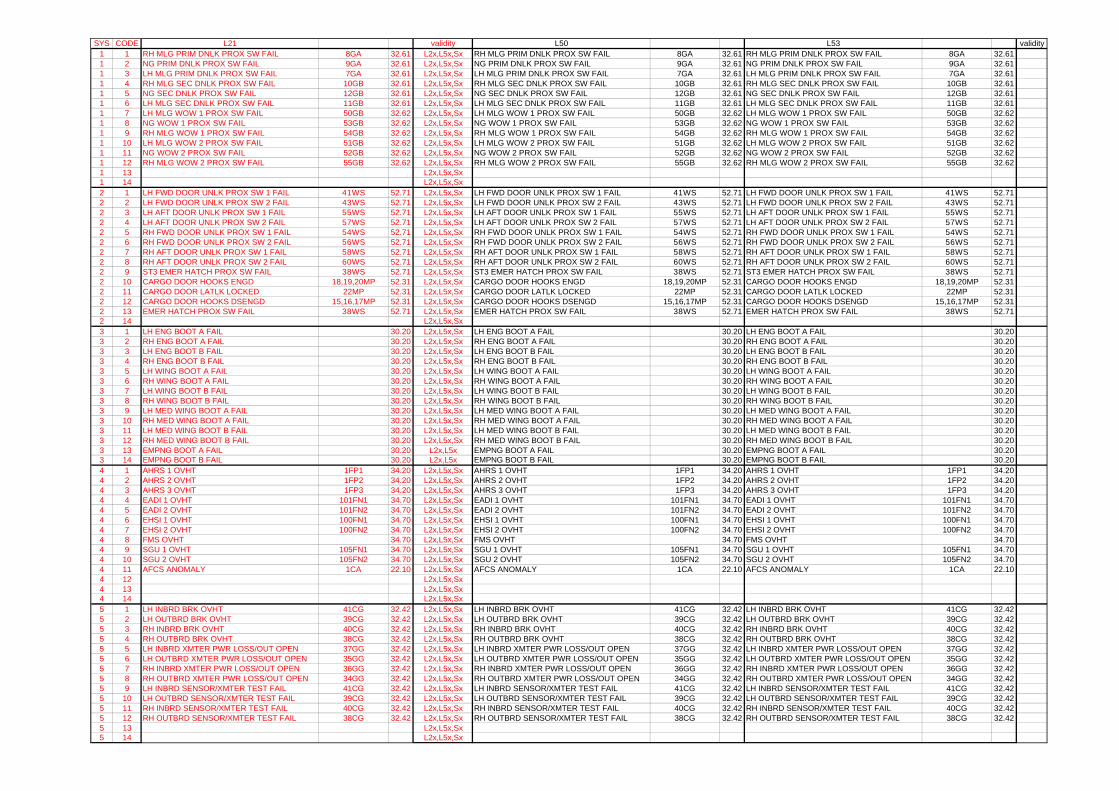
SYS CODE L21 validity L50 L53 validity1 1 RH MLG PRIM DNLK PROX SW FAIL 8GA 32.61 L2x,L5x,Sx RH MLG PRIM DNLK PROX SW FAIL 8GA 32.61 RH MLG PRIM DNLK PROX SW FAIL 8GA 32.611 2 NG PRIM DNLK PROX SW FAIL 9GA 32.61 L2x,L5x,Sx NG PRIM DNLK PROX SW FAIL 9GA 32.61 NG PRIM DNLK PROX SW FAIL 9GA 32.611 3 LH MLG PRIM DNLK PROX SW FAIL 7GA 32.61 L2x,L5x,Sx LH MLG PRIM DNLK PROX SW FAIL 7GA 32.61 LH MLG PRIM DNLK PROX SW FAIL 7GA 32.611 4 RH MLG SEC DNLK PROX SW FAIL 10GB 32.61 L2x,L5x,Sx RH MLG SEC DNLK PROX SW FAIL 10GB 32.61 RH MLG SEC DNLK PROX SW FAIL 10GB 32.611 5 NG SEC DNLK PROX SW FAIL 12GB 32.61 L2x,L5x,Sx NG SEC DNLK PROX SW FAIL 12GB 32.61 NG SEC DNLK PROX SW FAIL 12GB 32.611 6 LH MLG SEC DNLK PROX SW FAIL 11GB 32.61 L2x,L5x,Sx LH MLG SEC DNLK PROX SW FAIL 11GB 32.61 LH MLG SEC DNLK PROX SW FAIL 11GB 32.611 7 LH MLG WOW 1 PROX SW FAIL 50GB 32.62 L2x,L5x,Sx LH MLG WOW 1 PROX SW FAIL 50GB 32.62 LH MLG WOW 1 PROX SW FAIL 50GB 32.621 8 NG WOW 1 PROX SW FAIL 53GB 32.62 L2x,L5x,Sx NG WOW 1 PROX SW FAIL 53GB 32.62 NG WOW 1 PROX SW FAIL 53GB 32.621 9 RH MLG WOW 1 PROX SW FAIL 54GB 32.62 L2x,L5x,Sx RH MLG WOW 1 PROX SW FAIL 54GB 32.62 RH MLG WOW 1 PROX SW FAIL 54GB 32.621 10 LH MLG WOW 2 PROX SW FAIL 51GB 32.62 L2x,L5x,Sx LH MLG WOW 2 PROX SW FAIL 51GB 32.62 LH MLG WOW 2 PROX SW FAIL 51GB 32.621 11 NG WOW 2 PROX SW FAIL 52GB 32.62 L2x,L5x,Sx NG WOW 2 PROX SW FAIL 52GB 32.62 NG WOW 2 PROX SW FAIL 52GB 32.621 12 RH MLG WOW 2 PROX SW FAIL 55GB 32.62 L2x,L5x,Sx RH MLG WOW 2 PROX SW FAIL 55GB 32.62 RH MLG WOW 2 PROX SW FAIL 55GB 32.621 13 L2x,L5x,Sx1 14 L2x,L5x,Sx2 1 LH FWD DOOR UNLK PROX SW 1 FAIL 41WS 52.71 L2x,L5x,Sx LH FWD DOOR UNLK PROX SW 1 FAIL 41WS 52.71 LH FWD DOOR UNLK PROX SW 1 FAIL 41WS 52.712 2 LH FWD DOOR UNLK PROX SW 2 FAIL 43WS 52.71 L2x,L5x,Sx LH FWD DOOR UNLK PROX SW 2 FAIL 43WS 52.71 LH FWD DOOR UNLK PROX SW 2 FAIL 43WS 52.712 3 LH AFT DOOR UNLK PROX SW 1 FAIL 55WS 52.71 L2x,L5x,Sx LH AFT DOOR UNLK PROX SW 1 FAIL 55WS 52.71 LH AFT DOOR UNLK PROX SW 1 FAIL 55WS 52.712 4 LH AFT DOOR UNLK PROX SW 2 FAIL 57WS 52.71 L2x,L5x,Sx LH AFT DOOR UNLK PROX SW 2 FAIL 57WS 52.71 LH AFT DOOR UNLK PROX SW 2 FAIL 57WS 52.712 5 RH FWD DOOR UNLK PROX SW 1 FAIL 54WS 52.71 L2x,L5x,Sx RH FWD DOOR UNLK PROX SW 1 FAIL 54WS 52.71 RH FWD DOOR UNLK PROX SW 1 FAIL 54WS 52.712 6 RH FWD DOOR UNLK PROX SW 2 FAIL 56WS 52.71 L2x,L5x,Sx RH FWD DOOR UNLK PROX SW 2 FAIL 56WS 52.71 RH FWD DOOR UNLK PROX SW 2 FAIL 56WS 52.712 7 RH AFT DOOR UNLK PROX SW 1 FAIL 58WS 52.71 L2x,L5x,Sx RH AFT DOOR UNLK PROX SW 1 FAIL 58WS 52.71 RH AFT DOOR UNLK PROX SW 1 FAIL 58WS 52.712 8 RH AFT DOOR UNLK PROX SW 2 FAIL 60WS 52.71 L2x,L5x,Sx RH AFT DOOR UNLK PROX SW 2 FAIL 60WS 52.71 RH AFT DOOR UNLK PROX SW 2 FAIL 60WS 52.712 9 ST3 EMER HATCH PROX SW FAIL 38WS 52.71 L2x,L5x,Sx ST3 EMER HATCH PROX SW FAIL 38WS 52.71 ST3 EMER HATCH PROX SW FAIL 38WS 52.712 10 CARGO DOOR HOOKS ENGD 18,19,20MP 52.31 L2x,L5x,Sx CARGO DOOR HOOKS ENGD 18,19,20MP 52.31 CARGO DOOR HOOKS ENGD 18,19,20MP 52.312 11 CARGO DOOR LATLK LOCKED 22MP 52.31 L2x,L5x,Sx CARGO DOOR LATLK LOCKED 22MP 52.31 CARGO DOOR LATLK LOCKED 22MP 52.312 12 CARGO DOOR HOOKS DSENGD 15,16,17MP 52.31 L2x,L5x,Sx CARGO DOOR HOOKS DSENGD 15,16,17MP 52.31 CARGO DOOR HOOKS DSENGD 15,16,17MP 52.312 13 EMER HATCH PROX SW FAIL 38WS 52.71 L2x,L5x,Sx EMER HATCH PROX SW FAIL 38WS 52.71 EMER HATCH PROX SW FAIL 38WS 52.712 14 L2x,L5x,Sx3 1 LH ENG BOOT A FAIL 30.20 L2x,L5x,Sx LH ENG BOOT A FAIL 30.20 LH ENG BOOT A FAIL 30.203 2 RH ENG BOOT A FAIL 30.20 L2x,L5x,Sx RH ENG BOOT A FAIL 30.20 RH ENG BOOT A FAIL 30.203 3 LH ENG BOOT B FAIL 30.20 L2x,L5x,Sx LH ENG BOOT B FAIL 30.20 LH ENG BOOT B FAIL 30.203 4 RH ENG BOOT B FAIL 30.20 L2x,L5x,Sx RH ENG BOOT B FAIL 30.20 RH ENG BOOT B FAIL 30.203 5 LH WING BOOT A FAIL 30.20 L2x,L5x,Sx LH WING BOOT A FAIL 30.20 LH WING BOOT A FAIL 30.203 6 RH WING BOOT A FAIL 30.20 L2x,L5x,Sx RH WING BOOT A FAIL 30.20 RH WING BOOT A FAIL 30.203 7 LH WING BOOT B FAIL 30.20 L2x,L5x,Sx LH WING BOOT B FAIL 30.20 LH WING BOOT B FAIL 30.203 8 RH WING BOOT B FAIL 30.20 L2x,L5x,Sx RH WING BOOT B FAIL 30.20 RH WING BOOT B FAIL 30.203 9 LH MED WING BOOT A FAIL 30.20 L2x,L5x,Sx LH MED WING BOOT A FAIL 30.20 LH MED WING BOOT A FAIL 30.203 10 RH MED WING BOOT A FAIL 30.20 L2x,L5x,Sx RH MED WING BOOT A FAIL 30.20 RH MED WING BOOT A FAIL 30.203 11 LH MED WING BOOT B FAIL 30.20 L2x,L5x,Sx LH MED WING BOOT B FAIL 30.20 LH MED WING BOOT B FAIL 30.203 12 RH MED WING BOOT B FAIL 30.20 L2x,L5x,Sx RH MED WING BOOT B FAIL 30.20 RH MED WING BOOT B FAIL 30.203 13 EMPNG BOOT A FAIL 30.20 L2x,L5x EMPNG BOOT A FAIL 30.20 EMPNG BOOT A FAIL 30.203 14 EMPNG BOOT B FAIL 30.20 L2x,L5x EMPNG BOOT B FAIL 30.20 EMPNG BOOT B FAIL 30.204 1 AHRS 1 OVHT 1FP1 34.20 L2x,L5x,Sx AHRS 1 OVHT 1FP1 34.20 AHRS 1 OVHT 1FP1 34.204 2 AHRS 2 OVHT 1FP2 34.20 L2x,L5x,Sx AHRS 2 OVHT 1FP2 34.20 AHRS 2 OVHT 1FP2 34.204 3 AHRS 3 OVHT 1FP3 34.20 L2x,L5x,Sx AHRS 3 OVHT 1FP3 34.20 AHRS 3 OVHT 1FP3 34.204 4 EADI 1 OVHT 101FN1 34.70 L2x,L5x,Sx EADI 1 OVHT 101FN1 34.70 EADI 1 OVHT 101FN1 34.704 5 EADI 2 OVHT 101FN2 34.70 L2x,L5x,Sx EADI 2 OVHT 101FN2 34.70 EADI 2 OVHT 101FN2 34.704 6 EHSI 1 OVHT 100FN1 34.70 L2x,L5x,Sx EHSI 1 OVHT 100FN1 34.70 EHSI 1 OVHT 100FN1 34.704 7 EHSI 2 OVHT 100FN2 34.70 L2x,L5x,Sx EHSI 2 OVHT 100FN2 34.70 EHSI 2 OVHT 100FN2 34.704 8 FMS OVHT 34.70 L2x,L5x,Sx FMS OVHT 34.70 FMS OVHT 34.704 9 SGU 1 OVHT 105FN1 34.70 L2x,L5x,Sx SGU 1 OVHT 105FN1 34.70 SGU 1 OVHT 105FN1 34.704 10 SGU 2 OVHT 105FN2 34.70 L2x,L5x,Sx SGU 2 OVHT 105FN2 34.70 SGU 2 OVHT 105FN2 34.704 11 AFCS ANOMALY 1CA 22.10 L2x,L5x,Sx AFCS ANOMALY 1CA 22.10 AFCS ANOMALY 1CA 22.104 12 L2x,L5x,Sx4 13 L2x,L5x,Sx4 14 L2x,L5x,Sx5 1 LH INBRD BRK OVHT 41CG 32.42 L2x,L5x,Sx LH INBRD BRK OVHT 41CG 32.42 LH INBRD BRK OVHT 41CG 32.425 2 LH OUTBRD BRK OVHT 39CG 32.42 L2x,L5x,Sx LH OUTBRD BRK OVHT 39CG 32.42 LH OUTBRD BRK OVHT 39CG 32.425 3 RH INBRD BRK OVHT 40CG 32.42 L2x,L5x,Sx RH INBRD BRK OVHT 40CG 32.42 RH INBRD BRK OVHT 40CG 32.425 4 RH OUTBRD BRK OVHT 38CG 32.42 L2x,L5x,Sx RH OUTBRD BRK OVHT 38CG 32.42 RH OUTBRD BRK OVHT 38CG 32.425 5 LH INBRD XMTER PWR LOSS/OUT OPEN 37GG 32.42 L2x,L5x,Sx LH INBRD XMTER PWR LOSS/OUT OPEN 37GG 32.42 LH INBRD XMTER PWR LOSS/OUT OPEN 37GG 32.425 6 LH OUTBRD XMTER PWR LOSS/OUT OPEN 35GG 32.42 L2x,L5x,Sx LH OUTBRD XMTER PWR LOSS/OUT OPEN 35GG 32.42 LH OUTBRD XMTER PWR LOSS/OUT OPEN 35GG 32.425 7 RH INBRD XMTER PWR LOSS/OUT OPEN 36GG 32.42 L2x,L5x,Sx RH INBRD XMTER PWR LOSS/OUT OPEN 36GG 32.42 RH INBRD XMTER PWR LOSS/OUT OPEN 36GG 32.425 8 RH OUTBRD XMTER PWR LOSS/OUT OPEN 34GG 32.42 L2x,L5x,Sx RH OUTBRD XMTER PWR LOSS/OUT OPEN 34GG 32.42 RH OUTBRD XMTER PWR LOSS/OUT OPEN 34GG 32.425 9 LH INBRD SENSOR/XMTER TEST FAIL 41CG 32.42 L2x,L5x,Sx LH INBRD SENSOR/XMTER TEST FAIL 41CG 32.42 LH INBRD SENSOR/XMTER TEST FAIL 41CG 32.425 10 LH OUTBRD SENSOR/XMTER TEST FAIL 39CG 32.42 L2x,L5x,Sx LH OUTBRD SENSOR/XMTER TEST FAIL 39CG 32.42 LH OUTBRD SENSOR/XMTER TEST FAIL 39CG 32.425 11 RH INBRD SENSOR/XMTER TEST FAIL 40CG 32.42 L2x,L5x,Sx RH INBRD SENSOR/XMTER TEST FAIL 40CG 32.42 RH INBRD SENSOR/XMTER TEST FAIL 40CG 32.425 12 RH OUTBRD SENSOR/XMTER TEST FAIL 38CG 32.42 L2x,L5x,Sx RH OUTBRD SENSOR/XMTER TEST FAIL 38CG 32.42 RH OUTBRD SENSOR/XMTER TEST FAIL 38CG 32.425 13 L2x,L5x,Sx5 14 L2x,L5x,Sx
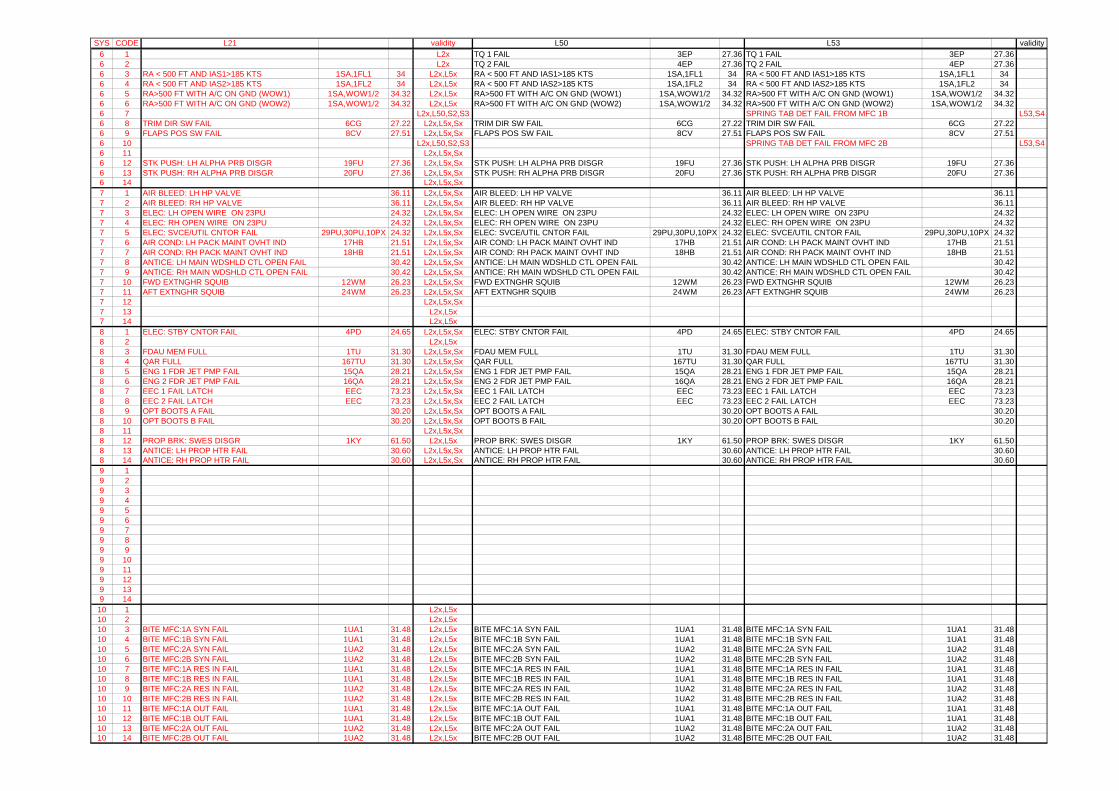
SYS CODE L21 validity L50 L53 validity6 1 L2x TQ 1 FAIL 3EP 27.36 TQ 1 FAIL 3EP 27.366 2 L2x TQ 2 FAIL 4EP 27.36 TQ 2 FAIL 4EP 27.366 3 RA < 500 FT AND IAS1>185 KTS 1SA,1FL1 34 L2x,L5x RA < 500 FT AND IAS1>185 KTS 1SA,1FL1 34 RA < 500 FT AND IAS1>185 KTS 1SA,1FL1 346 4 RA < 500 FT AND IAS2>185 KTS 1SA,1FL2 34 L2x,L5x RA < 500 FT AND IAS2>185 KTS 1SA,1FL2 34 RA < 500 FT AND IAS2>185 KTS 1SA,1FL2 346 5 RA>500 FT WITH A/C ON GND (WOW1) 1SA,WOW1/2 34.32 L2x,L5x RA>500 FT WITH A/C ON GND (WOW1) 1SA,WOW1/2 34.32 RA>500 FT WITH A/C ON GND (WOW1) 1SA,WOW1/2 34.326 6 RA>500 FT WITH A/C ON GND (WOW2) 1SA,WOW1/2 34.32 L2x,L5x RA>500 FT WITH A/C ON GND (WOW2) 1SA,WOW1/2 34.32 RA>500 FT WITH A/C ON GND (WOW2) 1SA,WOW1/2 34.326 7 L2x,L50,S2,S3 SPRING TAB DET FAIL FROM MFC 1B L53,S46 8 TRIM DIR SW FAIL 6CG 27.22 L2x,L5x,Sx TRIM DIR SW FAIL 6CG 27.22 TRIM DIR SW FAIL 6CG 27.226 9 FLAPS POS SW FAIL 8CV 27.51 L2x,L5x,Sx FLAPS POS SW FAIL 8CV 27.51 FLAPS POS SW FAIL 8CV 27.516 10 L2x,L50,S2,S3 SPRING TAB DET FAIL FROM MFC 2B L53,S46 11 L2x,L5x,Sx6 12 STK PUSH: LH ALPHA PRB DISGR 19FU 27.36 L2x,L5x,Sx STK PUSH: LH ALPHA PRB DISGR 19FU 27.36 STK PUSH: LH ALPHA PRB DISGR 19FU 27.366 13 STK PUSH: RH ALPHA PRB DISGR 20FU 27.36 L2x,L5x,Sx STK PUSH: RH ALPHA PRB DISGR 20FU 27.36 STK PUSH: RH ALPHA PRB DISGR 20FU 27.366 14 L2x,L5x,Sx7 1 AIR BLEED: LH HP VALVE 36.11 L2x,L5x,Sx AIR BLEED: LH HP VALVE 36.11 AIR BLEED: LH HP VALVE 36.117 2 AIR BLEED: RH HP VALVE 36.11 L2x,L5x,Sx AIR BLEED: RH HP VALVE 36.11 AIR BLEED: RH HP VALVE 36.117 3 ELEC: LH OPEN WIRE ON 23PU 24.32 L2x,L5x,Sx ELEC: LH OPEN WIRE ON 23PU 24.32 ELEC: LH OPEN WIRE ON 23PU 24.327 4 ELEC: RH OPEN WIRE ON 23PU 24.32 L2x,L5x,Sx ELEC: RH OPEN WIRE ON 23PU 24.32 ELEC: RH OPEN WIRE ON 23PU 24.327 5 ELEC: SVCE/UTIL CNTOR FAIL 29PU,30PU,10PX 24.32 L2x,L5x,Sx ELEC: SVCE/UTIL CNTOR FAIL 29PU,30PU,10PX 24.32 ELEC: SVCE/UTIL CNTOR FAIL 29PU,30PU,10PX 24.327 6 AIR COND: LH PACK MAINT OVHT IND 17HB 21.51 L2x,L5x,Sx AIR COND: LH PACK MAINT OVHT IND 17HB 21.51 AIR COND: LH PACK MAINT OVHT IND 17HB 21.517 7 AIR COND: RH PACK MAINT OVHT IND 18HB 21.51 L2x,L5x,Sx AIR COND: RH PACK MAINT OVHT IND 18HB 21.51 AIR COND: RH PACK MAINT OVHT IND 18HB 21.517 8 ANTICE: LH MAIN WDSHLD CTL OPEN FAIL 30.42 L2x,L5x,Sx ANTICE: LH MAIN WDSHLD CTL OPEN FAIL 30.42 ANTICE: LH MAIN WDSHLD CTL OPEN FAIL 30.427 9 ANTICE: RH MAIN WDSHLD CTL OPEN FAIL 30.42 L2x,L5x,Sx ANTICE: RH MAIN WDSHLD CTL OPEN FAIL 30.42 ANTICE: RH MAIN WDSHLD CTL OPEN FAIL 30.427 10 FWD EXTNGHR SQUIB 12WM 26.23 L2x,L5x,Sx FWD EXTNGHR SQUIB 12WM 26.23 FWD EXTNGHR SQUIB 12WM 26.237 11 AFT EXTNGHR SQUIB 24WM 26.23 L2x,L5x,Sx AFT EXTNGHR SQUIB 24WM 26.23 AFT EXTNGHR SQUIB 24WM 26.237 12 L2x,L5x,Sx7 13 L2x,L5x7 14 L2x,L5x8 1 ELEC: STBY CNTOR FAIL 4PD 24.65 L2x,L5x,Sx ELEC: STBY CNTOR FAIL 4PD 24.65 ELEC: STBY CNTOR FAIL 4PD 24.658 2 L2x,L5x8 3 FDAU MEM FULL 1TU 31.30 L2x,L5x,Sx FDAU MEM FULL 1TU 31.30 FDAU MEM FULL 1TU 31.308 4 QAR FULL 167TU 31.30 L2x,L5x,Sx QAR FULL 167TU 31.30 QAR FULL 167TU 31.308 5 ENG 1 FDR JET PMP FAIL 15QA 28.21 L2x,L5x,Sx ENG 1 FDR JET PMP FAIL 15QA 28.21 ENG 1 FDR JET PMP FAIL 15QA 28.218 6 ENG 2 FDR JET PMP FAIL 16QA 28.21 L2x,L5x,Sx ENG 2 FDR JET PMP FAIL 16QA 28.21 ENG 2 FDR JET PMP FAIL 16QA 28.218 7 EEC 1 FAIL LATCH EEC 73.23 L2x,L5x,Sx EEC 1 FAIL LATCH EEC 73.23 EEC 1 FAIL LATCH EEC 73.238 8 EEC 2 FAIL LATCH EEC 73.23 L2x,L5x,Sx EEC 2 FAIL LATCH EEC 73.23 EEC 2 FAIL LATCH EEC 73.238 9 OPT BOOTS A FAIL 30.20 L2x,L5x,Sx OPT BOOTS A FAIL 30.20 OPT BOOTS A FAIL 30.208 10 OPT BOOTS B FAIL 30.20 L2x,L5x,Sx OPT BOOTS B FAIL 30.20 OPT BOOTS B FAIL 30.208 11 L2x,L5x,Sx8 12 PROP BRK: SWES DISGR 1KY 61.50 L2x,L5x PROP BRK: SWES DISGR 1KY 61.50 PROP BRK: SWES DISGR 1KY 61.508 13 ANTICE: LH PROP HTR FAIL 30.60 L2x,L5x,Sx ANTICE: LH PROP HTR FAIL 30.60 ANTICE: LH PROP HTR FAIL 30.608 14 ANTICE: RH PROP HTR FAIL 30.60 L2x,L5x,Sx ANTICE: RH PROP HTR FAIL 30.60 ANTICE: RH PROP HTR FAIL 30.609 19 29 39 49 59 69 79 89 99 109 119 129 139 14
10 1 L2x,L5x10 2 L2x,L5x10 3 BITE MFC:1A SYN FAIL 1UA1 31.48 L2x,L5x BITE MFC:1A SYN FAIL 1UA1 31.48 BITE MFC:1A SYN FAIL 1UA1 31.4810 4 BITE MFC:1B SYN FAIL 1UA1 31.48 L2x,L5x BITE MFC:1B SYN FAIL 1UA1 31.48 BITE MFC:1B SYN FAIL 1UA1 31.4810 5 BITE MFC:2A SYN FAIL 1UA2 31.48 L2x,L5x BITE MFC:2A SYN FAIL 1UA2 31.48 BITE MFC:2A SYN FAIL 1UA2 31.4810 6 BITE MFC:2B SYN FAIL 1UA2 31.48 L2x,L5x BITE MFC:2B SYN FAIL 1UA2 31.48 BITE MFC:2B SYN FAIL 1UA2 31.4810 7 BITE MFC:1A RES IN FAIL 1UA1 31.48 L2x,L5x BITE MFC:1A RES IN FAIL 1UA1 31.48 BITE MFC:1A RES IN FAIL 1UA1 31.4810 8 BITE MFC:1B RES IN FAIL 1UA1 31.48 L2x,L5x BITE MFC:1B RES IN FAIL 1UA1 31.48 BITE MFC:1B RES IN FAIL 1UA1 31.4810 9 BITE MFC:2A RES IN FAIL 1UA2 31.48 L2x,L5x BITE MFC:2A RES IN FAIL 1UA2 31.48 BITE MFC:2A RES IN FAIL 1UA2 31.4810 10 BITE MFC:2B RES IN FAIL 1UA2 31.48 L2x,L5x BITE MFC:2B RES IN FAIL 1UA2 31.48 BITE MFC:2B RES IN FAIL 1UA2 31.4810 11 BITE MFC:1A OUT FAIL 1UA1 31.48 L2x,L5x BITE MFC:1A OUT FAIL 1UA1 31.48 BITE MFC:1A OUT FAIL 1UA1 31.4810 12 BITE MFC:1B OUT FAIL 1UA1 31.48 L2x,L5x BITE MFC:1B OUT FAIL 1UA1 31.48 BITE MFC:1B OUT FAIL 1UA1 31.4810 13 BITE MFC:2A OUT FAIL 1UA2 31.48 L2x,L5x BITE MFC:2A OUT FAIL 1UA2 31.48 BITE MFC:2A OUT FAIL 1UA2 31.4810 14 BITE MFC:2B OUT FAIL 1UA2 31.48 L2x,L5x BITE MFC:2B OUT FAIL 1UA2 31.48 BITE MFC:2B OUT FAIL 1UA2 31.48
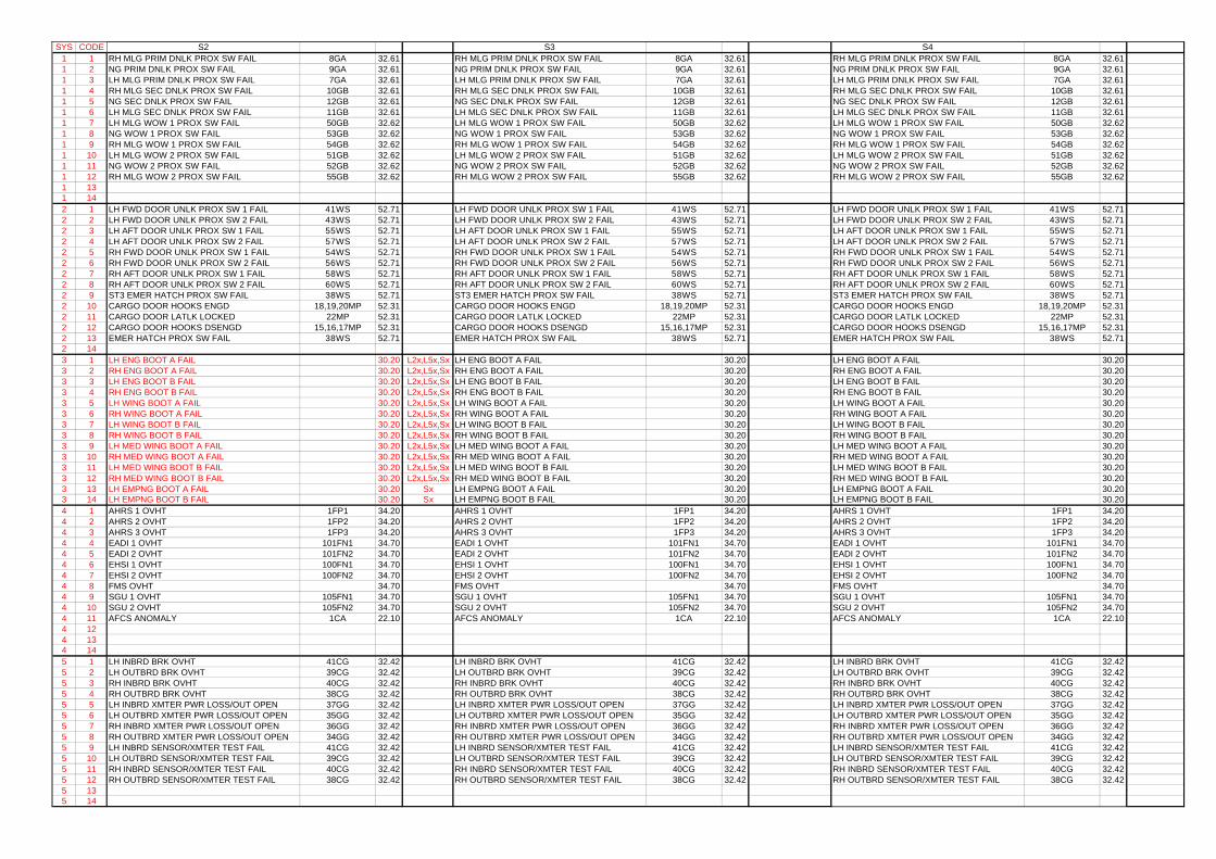
SYS CODE1 11 21 31 41 51 61 71 81 91 101 111 121 131 142 12 22 32 42 52 62 72 82 92 102 112 122 132 143 13 23 33 43 53 63 73 83 93 103 113 123 133 144 14 24 34 44 54 64 74 84 94 104 114 124 134 145 15 25 35 45 55 65 75 85 95 105 115 125 135 14
S2 S3 S4RH MLG PRIM DNLK PROX SW FAIL 8GA 32.61 RH MLG PRIM DNLK PROX SW FAIL 8GA 32.61 RH MLG PRIM DNLK PROX SW FAIL 8GA 32.61NG PRIM DNLK PROX SW FAIL 9GA 32.61 NG PRIM DNLK PROX SW FAIL 9GA 32.61 NG PRIM DNLK PROX SW FAIL 9GA 32.61LH MLG PRIM DNLK PROX SW FAIL 7GA 32.61 LH MLG PRIM DNLK PROX SW FAIL 7GA 32.61 LH MLG PRIM DNLK PROX SW FAIL 7GA 32.61RH MLG SEC DNLK PROX SW FAIL 10GB 32.61 RH MLG SEC DNLK PROX SW FAIL 10GB 32.61 RH MLG SEC DNLK PROX SW FAIL 10GB 32.61NG SEC DNLK PROX SW FAIL 12GB 32.61 NG SEC DNLK PROX SW FAIL 12GB 32.61 NG SEC DNLK PROX SW FAIL 12GB 32.61LH MLG SEC DNLK PROX SW FAIL 11GB 32.61 LH MLG SEC DNLK PROX SW FAIL 11GB 32.61 LH MLG SEC DNLK PROX SW FAIL 11GB 32.61LH MLG WOW 1 PROX SW FAIL 50GB 32.62 LH MLG WOW 1 PROX SW FAIL 50GB 32.62 LH MLG WOW 1 PROX SW FAIL 50GB 32.62NG WOW 1 PROX SW FAIL 53GB 32.62 NG WOW 1 PROX SW FAIL 53GB 32.62 NG WOW 1 PROX SW FAIL 53GB 32.62RH MLG WOW 1 PROX SW FAIL 54GB 32.62 RH MLG WOW 1 PROX SW FAIL 54GB 32.62 RH MLG WOW 1 PROX SW FAIL 54GB 32.62LH MLG WOW 2 PROX SW FAIL 51GB 32.62 LH MLG WOW 2 PROX SW FAIL 51GB 32.62 LH MLG WOW 2 PROX SW FAIL 51GB 32.62NG WOW 2 PROX SW FAIL 52GB 32.62 NG WOW 2 PROX SW FAIL 52GB 32.62 NG WOW 2 PROX SW FAIL 52GB 32.62RH MLG WOW 2 PROX SW FAIL 55GB 32.62 RH MLG WOW 2 PROX SW FAIL 55GB 32.62 RH MLG WOW 2 PROX SW FAIL 55GB 32.62
LH FWD DOOR UNLK PROX SW 1 FAIL 41WS 52.71 LH FWD DOOR UNLK PROX SW 1 FAIL 41WS 52.71 LH FWD DOOR UNLK PROX SW 1 FAIL 41WS 52.71LH FWD DOOR UNLK PROX SW 2 FAIL 43WS 52.71 LH FWD DOOR UNLK PROX SW 2 FAIL 43WS 52.71 LH FWD DOOR UNLK PROX SW 2 FAIL 43WS 52.71LH AFT DOOR UNLK PROX SW 1 FAIL 55WS 52.71 LH AFT DOOR UNLK PROX SW 1 FAIL 55WS 52.71 LH AFT DOOR UNLK PROX SW 1 FAIL 55WS 52.71LH AFT DOOR UNLK PROX SW 2 FAIL 57WS 52.71 LH AFT DOOR UNLK PROX SW 2 FAIL 57WS 52.71 LH AFT DOOR UNLK PROX SW 2 FAIL 57WS 52.71RH FWD DOOR UNLK PROX SW 1 FAIL 54WS 52.71 RH FWD DOOR UNLK PROX SW 1 FAIL 54WS 52.71 RH FWD DOOR UNLK PROX SW 1 FAIL 54WS 52.71RH FWD DOOR UNLK PROX SW 2 FAIL 56WS 52.71 RH FWD DOOR UNLK PROX SW 2 FAIL 56WS 52.71 RH FWD DOOR UNLK PROX SW 2 FAIL 56WS 52.71RH AFT DOOR UNLK PROX SW 1 FAIL 58WS 52.71 RH AFT DOOR UNLK PROX SW 1 FAIL 58WS 52.71 RH AFT DOOR UNLK PROX SW 1 FAIL 58WS 52.71RH AFT DOOR UNLK PROX SW 2 FAIL 60WS 52.71 RH AFT DOOR UNLK PROX SW 2 FAIL 60WS 52.71 RH AFT DOOR UNLK PROX SW 2 FAIL 60WS 52.71ST3 EMER HATCH PROX SW FAIL 38WS 52.71 ST3 EMER HATCH PROX SW FAIL 38WS 52.71 ST3 EMER HATCH PROX SW FAIL 38WS 52.71CARGO DOOR HOOKS ENGD 18,19,20MP 52.31 CARGO DOOR HOOKS ENGD 18,19,20MP 52.31 CARGO DOOR HOOKS ENGD 18,19,20MP 52.31CARGO DOOR LATLK LOCKED 22MP 52.31 CARGO DOOR LATLK LOCKED 22MP 52.31 CARGO DOOR LATLK LOCKED 22MP 52.31CARGO DOOR HOOKS DSENGD 15,16,17MP 52.31 CARGO DOOR HOOKS DSENGD 15,16,17MP 52.31 CARGO DOOR HOOKS DSENGD 15,16,17MP 52.31EMER HATCH PROX SW FAIL 38WS 52.71 EMER HATCH PROX SW FAIL 38WS 52.71 EMER HATCH PROX SW FAIL 38WS 52.71
LH ENG BOOT A FAIL 30.20 L2x,L5x,Sx LH ENG BOOT A FAIL 30.20 LH ENG BOOT A FAIL 30.20RH ENG BOOT A FAIL 30.20 L2x,L5x,Sx RH ENG BOOT A FAIL 30.20 RH ENG BOOT A FAIL 30.20LH ENG BOOT B FAIL 30.20 L2x,L5x,Sx LH ENG BOOT B FAIL 30.20 LH ENG BOOT B FAIL 30.20RH ENG BOOT B FAIL 30.20 L2x,L5x,Sx RH ENG BOOT B FAIL 30.20 RH ENG BOOT B FAIL 30.20LH WING BOOT A FAIL 30.20 L2x,L5x,Sx LH WING BOOT A FAIL 30.20 LH WING BOOT A FAIL 30.20RH WING BOOT A FAIL 30.20 L2x,L5x,Sx RH WING BOOT A FAIL 30.20 RH WING BOOT A FAIL 30.20LH WING BOOT B FAIL 30.20 L2x,L5x,Sx LH WING BOOT B FAIL 30.20 LH WING BOOT B FAIL 30.20RH WING BOOT B FAIL 30.20 L2x,L5x,Sx RH WING BOOT B FAIL 30.20 RH WING BOOT B FAIL 30.20LH MED WING BOOT A FAIL 30.20 L2x,L5x,Sx LH MED WING BOOT A FAIL 30.20 LH MED WING BOOT A FAIL 30.20RH MED WING BOOT A FAIL 30.20 L2x,L5x,Sx RH MED WING BOOT A FAIL 30.20 RH MED WING BOOT A FAIL 30.20LH MED WING BOOT B FAIL 30.20 L2x,L5x,Sx LH MED WING BOOT B FAIL 30.20 LH MED WING BOOT B FAIL 30.20RH MED WING BOOT B FAIL 30.20 L2x,L5x,Sx RH MED WING BOOT B FAIL 30.20 RH MED WING BOOT B FAIL 30.20LH EMPNG BOOT A FAIL 30.20 Sx LH EMPNG BOOT A FAIL 30.20 LH EMPNG BOOT A FAIL 30.20LH EMPNG BOOT B FAIL 30.20 Sx LH EMPNG BOOT B FAIL 30.20 LH EMPNG BOOT B FAIL 30.20AHRS 1 OVHT 1FP1 34.20 AHRS 1 OVHT 1FP1 34.20 AHRS 1 OVHT 1FP1 34.20AHRS 2 OVHT 1FP2 34.20 AHRS 2 OVHT 1FP2 34.20 AHRS 2 OVHT 1FP2 34.20AHRS 3 OVHT 1FP3 34.20 AHRS 3 OVHT 1FP3 34.20 AHRS 3 OVHT 1FP3 34.20EADI 1 OVHT 101FN1 34.70 EADI 1 OVHT 101FN1 34.70 EADI 1 OVHT 101FN1 34.70EADI 2 OVHT 101FN2 34.70 EADI 2 OVHT 101FN2 34.70 EADI 2 OVHT 101FN2 34.70EHSI 1 OVHT 100FN1 34.70 EHSI 1 OVHT 100FN1 34.70 EHSI 1 OVHT 100FN1 34.70EHSI 2 OVHT 100FN2 34.70 EHSI 2 OVHT 100FN2 34.70 EHSI 2 OVHT 100FN2 34.70FMS OVHT 34.70 FMS OVHT 34.70 FMS OVHT 34.70SGU 1 OVHT 105FN1 34.70 SGU 1 OVHT 105FN1 34.70 SGU 1 OVHT 105FN1 34.70SGU 2 OVHT 105FN2 34.70 SGU 2 OVHT 105FN2 34.70 SGU 2 OVHT 105FN2 34.70AFCS ANOMALY 1CA 22.10 AFCS ANOMALY 1CA 22.10 AFCS ANOMALY 1CA 22.10
LH INBRD BRK OVHT 41CG 32.42 LH INBRD BRK OVHT 41CG 32.42 LH INBRD BRK OVHT 41CG 32.42LH OUTBRD BRK OVHT 39CG 32.42 LH OUTBRD BRK OVHT 39CG 32.42 LH OUTBRD BRK OVHT 39CG 32.42RH INBRD BRK OVHT 40CG 32.42 RH INBRD BRK OVHT 40CG 32.42 RH INBRD BRK OVHT 40CG 32.42RH OUTBRD BRK OVHT 38CG 32.42 RH OUTBRD BRK OVHT 38CG 32.42 RH OUTBRD BRK OVHT 38CG 32.42LH INBRD XMTER PWR LOSS/OUT OPEN 37GG 32.42 LH INBRD XMTER PWR LOSS/OUT OPEN 37GG 32.42 LH INBRD XMTER PWR LOSS/OUT OPEN 37GG 32.42LH OUTBRD XMTER PWR LOSS/OUT OPEN 35GG 32.42 LH OUTBRD XMTER PWR LOSS/OUT OPEN 35GG 32.42 LH OUTBRD XMTER PWR LOSS/OUT OPEN 35GG 32.42RH INBRD XMTER PWR LOSS/OUT OPEN 36GG 32.42 RH INBRD XMTER PWR LOSS/OUT OPEN 36GG 32.42 RH INBRD XMTER PWR LOSS/OUT OPEN 36GG 32.42RH OUTBRD XMTER PWR LOSS/OUT OPEN 34GG 32.42 RH OUTBRD XMTER PWR LOSS/OUT OPEN 34GG 32.42 RH OUTBRD XMTER PWR LOSS/OUT OPEN 34GG 32.42LH INBRD SENSOR/XMTER TEST FAIL 41CG 32.42 LH INBRD SENSOR/XMTER TEST FAIL 41CG 32.42 LH INBRD SENSOR/XMTER TEST FAIL 41CG 32.42LH OUTBRD SENSOR/XMTER TEST FAIL 39CG 32.42 LH OUTBRD SENSOR/XMTER TEST FAIL 39CG 32.42 LH OUTBRD SENSOR/XMTER TEST FAIL 39CG 32.42RH INBRD SENSOR/XMTER TEST FAIL 40CG 32.42 RH INBRD SENSOR/XMTER TEST FAIL 40CG 32.42 RH INBRD SENSOR/XMTER TEST FAIL 40CG 32.42RH OUTBRD SENSOR/XMTER TEST FAIL 38CG 32.42 RH OUTBRD SENSOR/XMTER TEST FAIL 38CG 32.42 RH OUTBRD SENSOR/XMTER TEST FAIL 38CG 32.42
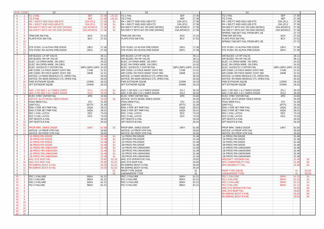
SYS CODE1 16 16 26 36 46 56 66 76 86 96 106 116 126 136 147 17 27 37 47 57 67 77 87 97 107 117 127 137 148 18 28 38 48 58 68 78 88 98 108 118 128 138 149 19 29 39 49 59 69 79 89 99 109 119 129 139 14
10 110 210 310 410 510 610 710 810 910 1010 1110 1210 1310 14
S2 S3 S4TQ 1 FAIL 3EP 27.36 L5x,Sx TQ 1 FAIL 3EP 27.36 TQ 1 FAIL 3EP 27.36TQ 2 FAIL 4EP 27.36 L5x,Sx TQ 2 FAIL 4EP 27.36 TQ 2 FAIL 4EP 27.36RA < 500 FT AND IAS1>185 KTS 1SA,1FL1 27.36 Sx RA < 500 FT AND IAS1>185 KTS 1SA,1FL1 27.36 RA < 500 FT AND IAS1>185 KTS 1SA,1FL1 27.36RA < 500 FT AND IAS2>185 KTS 1SA,1FL2 27.36 Sx RA < 500 FT AND IAS2>185 KTS 1SA,1FL2 27.36 RA < 500 FT AND IAS2>185 KTS 1SA,1FL2 27.36RA>500 FT WITH A/C ON GND (WOW1) 1SA,WOW1/2 27.36 Sx RA>500 FT WITH A/C ON GND (WOW1) 1SA,WOW1/2 27.36 RA>500 FT WITH A/C ON GND (WOW1) 1SA,WOW1/2 27.36RA>500 FT WITH A/C ON GND (WOW2) 1SA,WOW1/2 27.36 Sx RA>500 FT WITH A/C ON GND (WOW2) 1SA,WOW1/2 27.36 RA>500 FT WITH A/C ON GND (WOW2) 1SA,WOW1/2 27.36
SPRING TAB DET FAIL FROM MFC 1B 27.72TRIM DIR SW FAIL 6CG 27.22 TRIM DIR SW FAIL 6CG 27.22 TRIM DIR SW FAIL 6CG 27.22FLAPS POS SW FAIL 8CV 27.51 FLAPS POS SW FAIL 8CV 27.51 FLAPS POS SW FAIL 8CV 27.51
SPRING TAB DET FAIL FROM MFC 2B 27.72
STK PUSH: LH ALPHA PRB DISGR 19FU 27.36 STK PUSH: LH ALPHA PRB DISGR 19FU 27.36 STK PUSH: LH ALPHA PRB DISGR 19FU 27.36STK PUSH: RH ALPHA PRB DISGR 20FU 27.36 STK PUSH: RH ALPHA PRB DISGR 20FU 27.36 STK PUSH: RH ALPHA PRB DISGR 20FU 27.36
AIR BLEED: LH HP VALVE 36.11 AIR BLEED: LH HP VALVE 36.11 AIR BLEED: LH HP VALVE 36.11AIR BLEED: RH HP VALVE 36.11 AIR BLEED: RH HP VALVE 36.11 AIR BLEED: RH HP VALVE 36.11ELEC: LH OPEN WIRE ON 23PU 24.32 ELEC: LH OPEN WIRE ON 23PU 24.32 ELEC: LH OPEN WIRE ON 23PU 24.32ELEC: RH OPEN WIRE ON 23PU 24.32 ELEC: RH OPEN WIRE ON 23PU 24.32 ELEC: RH OPEN WIRE ON 23PU 24.32ELEC: SVCE/UTLY CNTOR FAIL 29PU,30PU,10PX 24.32 ELEC: SVCE/UTLY CNTOR FAIL 29PU,30PU,10PX 24.32 ELEC: SVCE/UTLY CNTOR FAIL 29PU,30PU,10PX 24.32AIR COND: LH PACK MAINT OVHT IND 17HB 21.51 AIR COND: LH PACK MAINT OVHT IND 17HB 21.51 AIR COND: LH PACK MAINT OVHT IND 17HB 21.51AIR COND: RH PACK MAINT OVHT IND 18HB 21.51 AIR COND: RH PACK MAINT OVHT IND 18HB 21.51 AIR COND: RH PACK MAINT OVHT IND 18HB 21.51ANTICE: LH MAIN WDSHLD CTL OPEN FAIL 30.42 ANTICE: LH MAIN WDSHLD CTL OPEN FAIL 30.42 ANTICE: LH MAIN WDSHLD CTL OPEN FAIL 30.42ANTICE: RH MAIN WDSHLD CTL OPEN FAIL 30.42 ANTICE: RH MAIN WDSHLD CTL OPEN FAIL 30.42 ANTICE: RH MAIN WDSHLD CTL OPEN FAIL 30.42FWD EXTNGHR SQUIB 12WM 26.23 FWD EXTNGHR SQUIB 12WM 26.23 FWD EXTNGHR SQUIB 12WM 26.23AFT EXTNGHR SQUIB 24WM 26.23 AFT EXTNGHR SQUIB 24WM 26.23 AFT EXTNGHR SQUIB 24WM 26.23
ADC 1 OR ADC 1 & 2 SWES DISGR 1FL1 30.20 Sx ADC 1 OR ADC 1 & 2 SWES DISGR 1FL1 30.20 ADC 1 OR ADC 1 & 2 SWES DISGR 1FL1 30.20ADC 2 OR ADC 2 & 1 SWES DISGR 1FL2 30.20 Sx ADC 2 OR ADC 2 & 1 SWES DISGR 1FL2 30.20 ADC 2 OR ADC 2 & 1 SWES DISGR 1FL2 30.20ELEC: STBY CNTOR FAIL 4PD 24.65 ELEC: STBY CNTOR FAIL 4PD 24.65 ELEC: STBY CNTOR FAIL 4PD 24.65ANTICE: AUTO MODE SWES DISGR 30.20 Sx ANTICE: AUTO MODE SWES DISGR 30.20 ANTICE: AUTO MODE SWES DISGR 30.20FDAU MEM FULL 1TU 31.30 FDAU MEM FULL 1TU 31.30 FDAU MEM FULL 1TU 31.30QAR FULL 167TU 31.30 QAR FULL 167TU 31.30 QAR FULL 167TU 31.30ENG 1 FDR JET PMP FAIL 15QA 28.21 ENG 1 FDR JET PMP FAIL 15QA 28.21 ENG 1 FDR JET PMP FAIL 15QA 28.21ENG 2 FDR JET PMP FAIL 16QA 28.21 ENG 2 FDR JET PMP FAIL 16QA 28.21 ENG 2 FDR JET PMP FAIL 16QA 28.21EEC 1 FAIL LATCH EEC 73.23 EEC 1 FAIL LATCH EEC 73.23 EEC 1 FAIL LATCH EEC 73.23EEC 2 FAIL LATCH EEC 73.23 EEC 2 FAIL LATCH EEC 73.23 EEC 2 FAIL LATCH EEC 73.23OPT BOOTS A FAIL 30.20 OPT BOOTS A FAIL 30.20 OPT BOOTS A FAIL 30.20OPT BOOTS B FAIL 30.20 OPT BOOTS B FAIL 30.20 OPT BOOTS B FAIL 30.20
PROP BRK: SWES DISGR 14KY 61.50 Sx PROP BRK: SWES DISGR 14KY 61.50 PROP BRK: SWES DISGR 14KY 61.50ANTICE: LH PROP HTR FAIL 30.60 ANTICE: LH PROP HTR FAIL 30.60 ANTICE: LH PROP HTR FAIL 30.60ANTICE: RH PROP HTR FAIL 30.60 ANTICE: RH PROP HTR FAIL 30.60 ANTICE: RH PROP HTR FAIL 30.60 1A PROG PIN DISGR 31.48 Sx 1A PROG PIN DISGR 31.48 1A PROG PIN DISGR 31.48 1B PROG PIN DISGR 31.48 Sx 1B PROG PIN DISGR 31.48 1B PROG PIN DISGR 31.48 2A PROG PIN DISGR 31.48 Sx 2A PROG PIN DISGR 31.48 2A PROG PIN DISGR 31.48 2B PROG PIN DISGR 31.48 Sx 2B PROG PIN DISGR 31.48 2B PROG PIN DISGR 31.48 1A PROG PIN UNKNOWN 31.48 Sx 1A PROG PIN UNKNOWN 31.48 1A PROG PIN UNKNOWN 31.48 1B PROG PIN UNKNOWN 31.48 Sx 1B PROG PIN UNKNOWN 31.48 1B PROG PIN UNKNOWN 31.48 2A PROG PIN UNKNOWN 31.48 Sx 2A PROG PIN UNKNOWN 31.48 2A PROG PIN UNKNOWN 31.48 2B PROG PIN UNKNOWN 31.48 Sx 2B PROG PIN UNKNOWN 31.48 2B PROG PIN UNKNOWN 31.48ANC SYS INOP FAIL 25.82 S2,S3 ANC SYS OPERATIVE FAIL 25.82 AIRCRAFT VERSION FAIL 31.48 S4ANC SYS INOP FAIL 25.82 S2,S3 ANC SYS INOP FAIL 25.82 MFC COMPATIBILITY FAIL 31.48 S4RH EMPNG BOOT A FAIL 30.20 S2,S3 RH EMPNG BOOT A FAIL 30.20 MFC MIXABILITY FAIL 31.48 S4RH EMPNG BOOT B FAIL 30.20 S2,S3 RH EMPNG BOOT B FAIL 30.20
S2 PROP TYPE DISGR 61 PROP TYPE DISGR 61 S3,S4S2 UNKWNPROP TYPE 61 UNKWNPROP TYPE 61 S3,S4
PEC 1 FAILURE 50KH 61.21 PEC 1 FAILURE 50KH 61.21 PEC 1 FAILURE 50KH 61.21 SxPIU 1 FAILURE 95KH 61.21 PIU 1 FAILURE 95KH 61.21 PIU 1 FAILURE 95KH 61.21 SxPEC 2 FAILURE 50KH 61.21 PEC 2 FAILURE 50KH 61.21 PEC 2 FAILURE 50KH 61.21 SxPIU 2 FAILURE 96KH 61.21 PIU 2 FAILURE 96KH 61.21 PIU 2 FAILURE 96KH 61.21 Sx
ANC SYS OPERATIVE FAIL 25.82 S4ANC SYS INOP FAIL 25.82 S4RH EMPNG BOOT A FAIL 30.20 S4RH EMPNG BOOT B FAIL 30.20 S4
Page 1 sur 5
COM/NAV MAINTENANCEDIAGNOSTIC CODES
REFERENCE DO/TY 3170/04 Ed.01
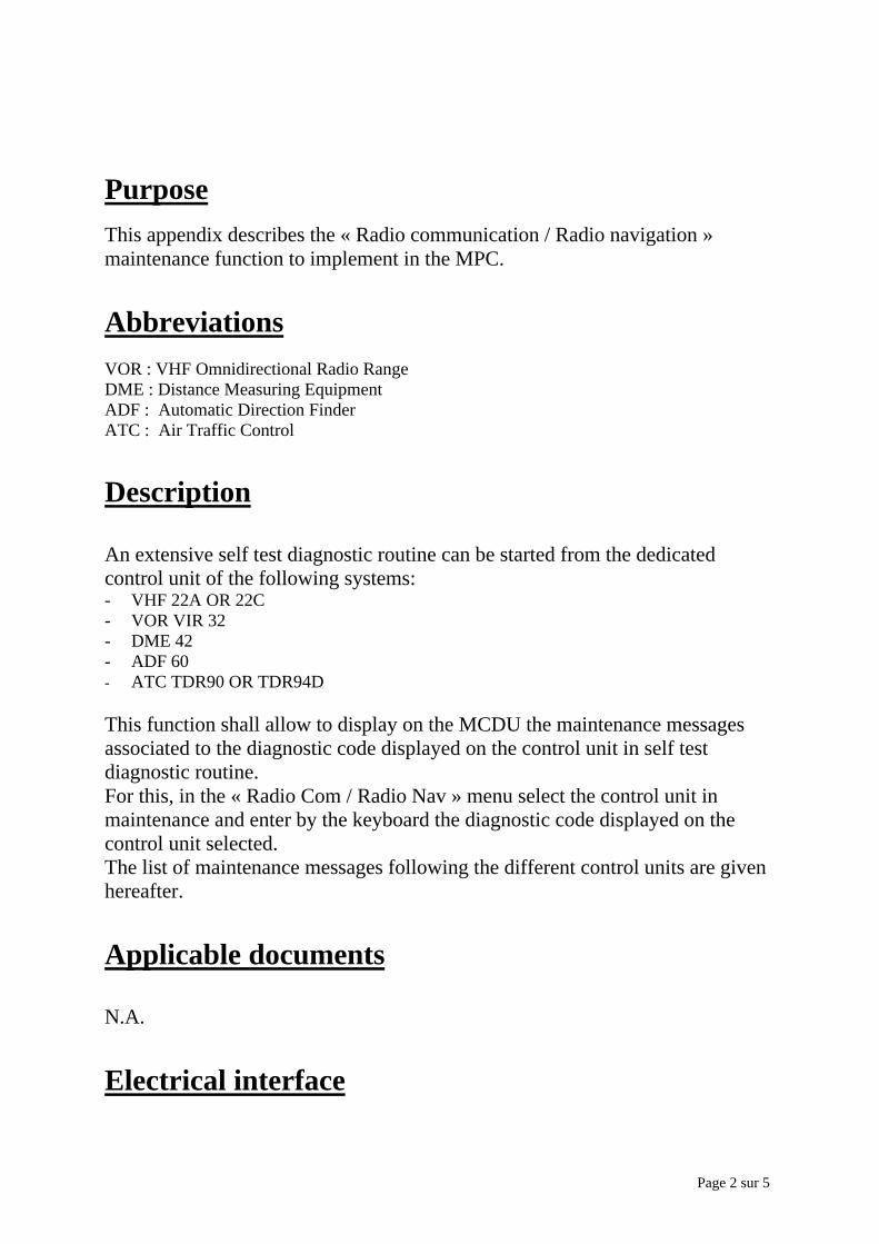
Page 2 sur 5
PurposeThis appendix describes the « Radio communication / Radio navigation »maintenance function to implement in the MPC.
AbbreviationsVOR : VHF Omnidirectional Radio RangeDME : Distance Measuring EquipmentADF : Automatic Direction FinderATC : Air Traffic Control
Description
An extensive self test diagnostic routine can be started from the dedicatedcontrol unit of the following systems:- VHF 22A OR 22C- VOR VIR 32- DME 42- ADF 60- ATC TDR90 OR TDR94D
This function shall allow to display on the MCDU the maintenance messagesassociated to the diagnostic code displayed on the control unit in self testdiagnostic routine.For this, in the « Radio Com / Radio Nav » menu select the control unit inmaintenance and enter by the keyboard the diagnostic code displayed on thecontrol unit selected.The list of maintenance messages following the different control units are givenhereafter.
Applicable documents
N.A.
Electrical interface

Page 3 sur 5
N.A.
Software level requirement
The software shall be in accordance with DO178B level D.
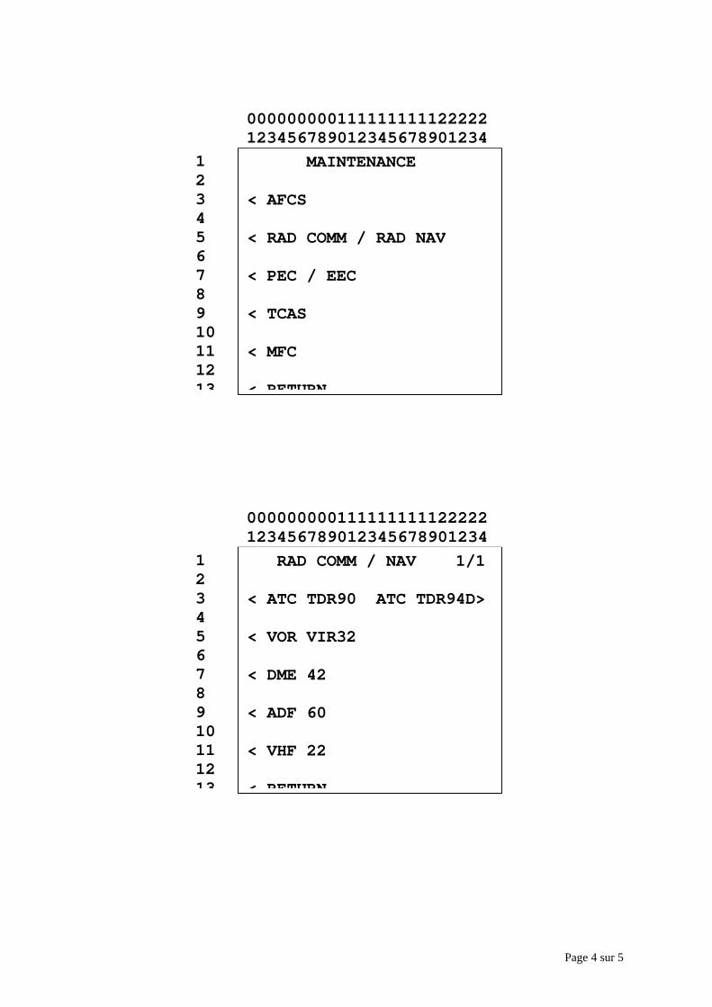
Page 4 sur 5
RAD COMM / NAV 1/1
< ATC TDR90 ATC TDR94D>
< VOR VIR32
< DME 42
< ADF 60
< VHF 22
< RETURN
12345678910111213
000000000111111111122222123456789012345678901234
MAINTENANCE
< AFCS
< RAD COMM / RAD NAV
< PEC / EEC
< TCAS
< MFC
< RETURN
12345678910111213
000000000111111111122222123456789012345678901234
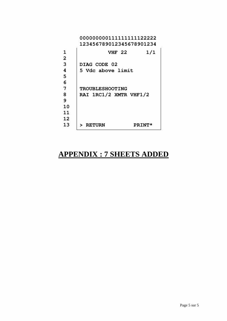
Page 5 sur 5
APPENDIX : 7 SHEETS ADDED
VHF 22 1/1
DIAG CODE 02 5 Vdc above limit
TROUBLESHOOTINGRAI 1RC1/2 XMTR VHF1/2
> RETURN PRINT*
1234567891011121314
000000000111111111122222123456789012345678901234

ADF 60CODE DESCRIPTION TROUBLESHOOTING
00 No fault found02 RAM test FAILED RAI 151RP1/2 ADAPTER ADF03 No serial sync RAI 3RP1/2 CTL ADF04 No serial data RAI 3RP1/2 CTL ADF05 No label received RAI 3RP1/2 CTL ADF06 I/O port 1 failure RAI 151RP1/2 ADAPTER ADF07 I/O port 2 failure RAI 151RP1/2 ADAPTER ADF08 Illegal ADF frequency RAI 3RP1/2 CTL ADF09 Serial input failed RAI 151RP1/2 or 3RP1/210 ADF not locked RAI 1RP1/2 or 151RP1/2
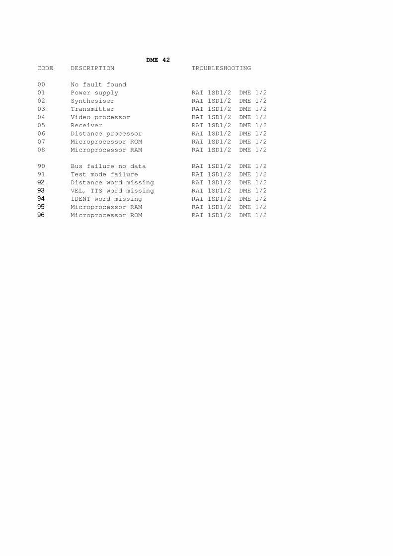
DME 42CODE DESCRIPTION TROUBLESHOOTING
00 No fault found01 Power supply RAI 1SD1/2 DME 1/202 Synthesiser RAI 1SD1/2 DME 1/203 Transmitter RAI 1SD1/2 DME 1/204 Video processor RAI 1SD1/2 DME 1/205 Receiver RAI 1SD1/2 DME 1/206 Distance processor RAI 1SD1/2 DME 1/207 Microprocessor ROM RAI 1SD1/2 DME 1/208 Microprocessor RAM RAI 1SD1/2 DME 1/2
90 Bus failure no data RAI 1SD1/2 DME 1/291 Test mode failure RAI 1SD1/2 DME 1/292 Distance word missing RAI 1SD1/2 DME 1/293 VEL, TTS word missing RAI 1SD1/2 DME 1/294 IDENT word missing RAI 1SD1/2 DME 1/295 Microprocessor RAM RAI 1SD1/2 DME 1/296 Microprocessor ROM RAI 1SD1/2 DME 1/2
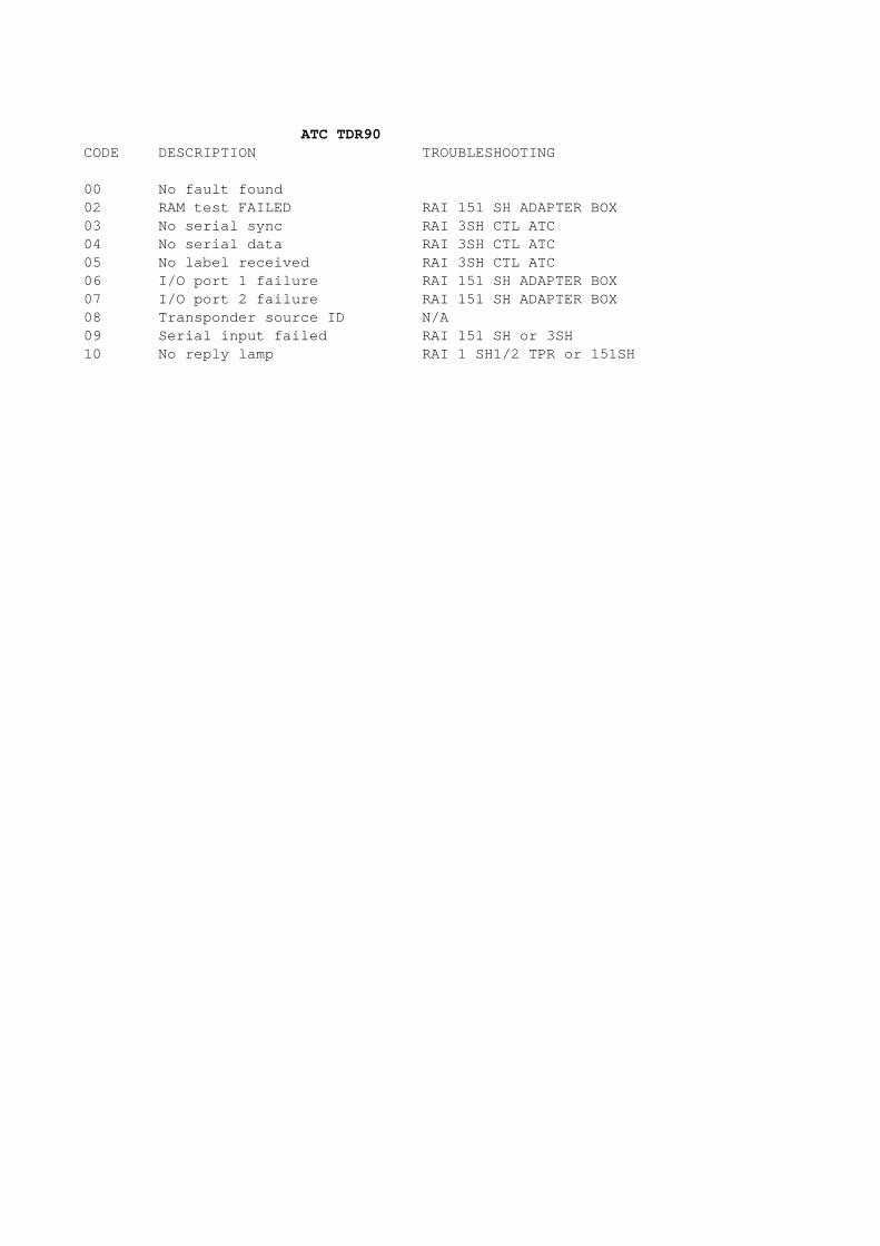
ATC TDR90CODE DESCRIPTION TROUBLESHOOTING
00 No fault found02 RAM test FAILED RAI 151 SH ADAPTER BOX03 No serial sync RAI 3SH CTL ATC04 No serial data RAI 3SH CTL ATC05 No label received RAI 3SH CTL ATC06 I/O port 1 failure RAI 151 SH ADAPTER BOX07 I/O port 2 failure RAI 151 SH ADAPTER BOX08 Transponder source ID N/A09 Serial input failed RAI 151 SH or 3SH10 No reply lamp RAI 1 SH1/2 TPR or 151SH
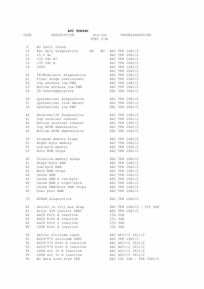
ATC TDR94DCODE DESCRIPTION sta tus TROUBLESHOOTING
STBY F/W
0 No fault found10 Pwr Sply diagnostics NO NO RAI TPR 1SH1/211 +5 V dc RAI TPR 1SH1/212 +70 Vdc B7 RAI TPR 1SH1/213 +35 Vdc B RAI TPR 1SH1/214 LVPS RAI TPR 1SH1/2
RAI TPR 1SH1/220 TX/Modulator diagnostics RAI TPR 1SH1/221 Final stage overcurrent RAI TPR 1SH1/222 Top antenna low PWR RAI TPR 1SH1/223 Bottom antenna low PWR RAI TPR 1SH1/224 TX Overtemperature RAI TPR 1SH1/2
30 Synthetizer diagnostics RAI TPR 1SH1/231 Synthetizer lock detect RAI TPR 1SH1/232 Synthetizer low PWR RAI TPR 1SH1/2
40 Receiver/IF diagnostics RAI TPR 1SH1/241 Top receiver channel RAI TPR 1SH1/242 Bottom receiver channel RAI TPR 1SH1/243 Top DPSK demodulator RAI TPR 1SH1/244 Bottom DPSK demodulator RAI TPR 1SH1/2
50 Program memory Diags RAI TPR 1SH1/251 Hight-byte memory RAI TPR 1SH1/252 Low-byte memory RAI TPR 1SH1/253 Both ROM chips RAI TPR 1SH1/2
60 Volatile memory diags RAI TPR 1SH1/261 Hight-byte RAM RAI TPR 1SH1/262 Low-byte RAM RAI TPR 1SH1/263 Both RAM chips RAI TPR 1SH1/264 Cache RAM RAI TPR 1SH1/265 Cache RAM & low-byte RAI TPR 1SH1/266 Cache RAM & hight-byte RAI TPR 1SH1/267 Cache RAM/both RAM chips RAI TPR 1SH1/268 Dual port RAM RAI TPR 1SH1/2
70 NVRAM diagnostics RAI TPR 1SH1/2
80 Serial in ctrl bus diag RAI TPR 1SH1/2 - CTL 3SH81 Arinc 429 control UART RAI TPR 1SH1/282 A429 Port A inactive CTL 3SH83 A429 Port B inactive CTL 3SH84 A429 Port C inactive CTL 3SH85 CSDB Port A inactive CTL 3SH
90 Serial altitude input RAI ADC1/2 1FL1/291 A429/575 altitude UART RAI TPR 1SH1/292 A429/575 Port A inactive RAI ADC1/2 1FL1/293 A429/575 Port B inactive RAI ADC1/2 1FL1/294 CSDB alt In A inactive RAI ADC1/2 1FL1/295 CSDB alt In B inactive RAI ADC1/2 1FL1/299 No data rcvd from TDR RAI CTL 3SH - TPR 1SH1/2
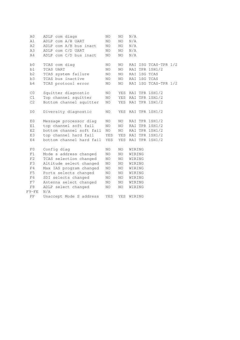
A0 ADLP com diags NO NO N/AA1 ADLP com A/B UART NO NO N/AA2 ADLP com A/B bus inact NO NO N/AA3 ADLP com C/D UART NO NO N/AA4 ADLP com C/D bus inact NO NO N/A
b0 TCAS com diag NO NO RAI ISG TCAS-TPR 1/2b1 TCAS UART NO NO RAI TPR 1SH1/2b2 TCAS system failure NO NO RAI 1SG TCASb3 TCAS bus inactive NO NO RAI 1SG TCASb4 TCAS protocol error NO NO RAI 1SG TCAS-TPR 1/2
C0 Squitter diagnostic NO YES RAI TPR 1SH1/2C1 Top channel squitter NO YES RAI TPR 1SH1/2C2 Bottom channel squitter NO YES RAI TPR 1SH1/2
D0 Diversity diagnostic NO YES RAI TPR 1SH1/2
E0 Message processor diag NO NO RAI TPR 1SH1/2E1 top channel soft fail NO NO RAI TPR 1SH1/2E2 bottom channel soft fail NO NO RAI TPR 1SH1/2E3 top channel hard fail YES YES RAI TPR 1SH1/2E4 bottom channel hard fail YES YES RAI TPR 1SH1/2
F0 Config diag NO NO WIRINGF1 Mode s address changed NO NO WIRINGF2 TCAS selection changed NO NO WIRINGF3 Altitude select changed NO NO WIRINGF4 Max IAS program changed NO NO WIRINGF5 Ports selects changed NO NO WIRINGF6 SDI selects changed NO NO WIRINGF7 Antenna select changed NO NO WIRINGF8 ADLP select changed NO NO WIRING
F9-FE N/AFF Unaccept Mode S address YES YES WIRING
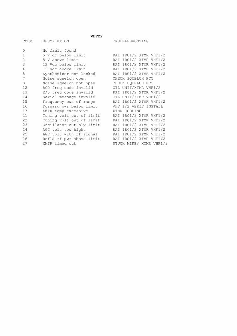
VHF22CODE DESCRIPTION TROUBLESHOOTING
0 No fault found1 5 V dc below limit RAI 1RC1/2 XTMR VHF1/22 5 V above limit RAI 1RC1/2 XTMR VHF1/23 12 Vdc below limit RAI 1RC1/2 XTMR VHF1/24 12 Vdc above limit RAI 1RC1/2 XTMR VHF1/25 Synthetizer not locked RAI 1RC1/2 XTMR VHF1/27 Noise squelch open CHECK SQUELCH FCT8 Noise squelch not open CHECK SQUELCH FCT12 BCD freq code invalid CTL UNIT/XTMR VHF1/213 2/5 freq code invalid RAI 1RC1/2 XTMR VHF1/214 Serial message invalid CTL UNIT/XTMR VHF1/215 Frequency out of range RAI 1RC1/2 XTMR VHF1/216 Forward pwr below limit VHF 1/2 VERIF INSTALL17 XMTR temp excessive XTMR COOLING21 Tuning volt out of limit RAI 1RC1/2 XTMR VHF1/222 Tuning volt out of limit RAI 1RC1/2 XTMR VHF1/223 Oscillator out blw limit RAI 1RC1/2 XTMR VHF1/224 AGC volt too hight RAI 1RC1/2 XTMR VHF1/225 AGC volt with rf signal RAI 1RC1/2 XTMR VHF1/226 Refld rf pwr above limit RAI 1RC1/2 XTMR VHF1/227 XMTR timed out STUCK MIKE/ XTMR VHF1/2
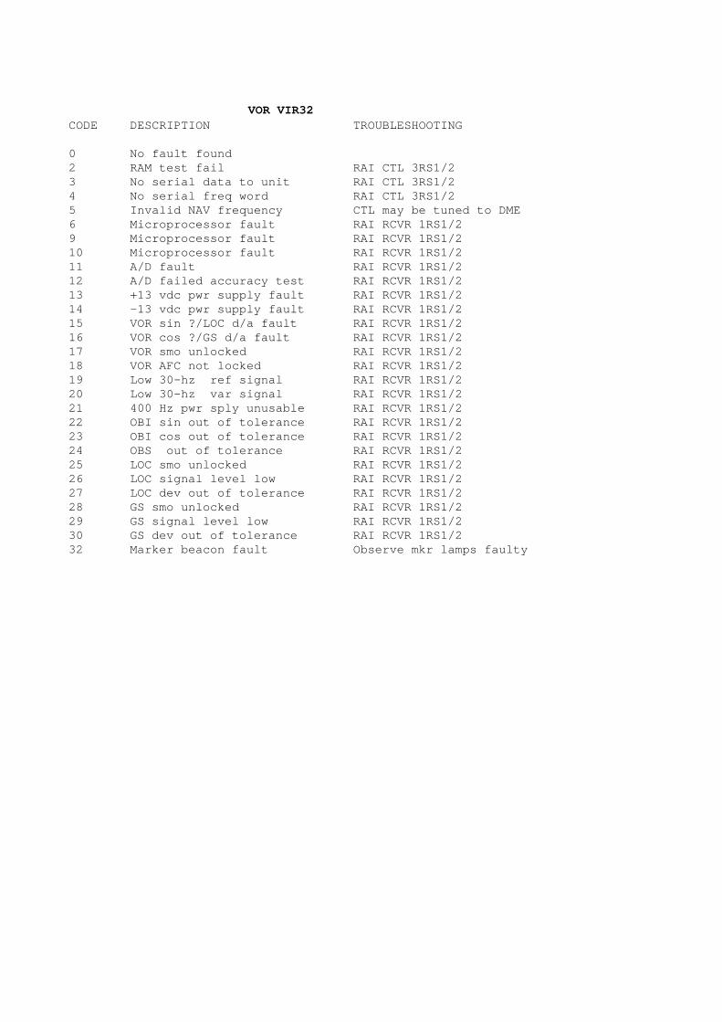
VOR VIR32CODE DESCRIPTION TROUBLESHOOTING
0 No fault found2 RAM test fail RAI CTL 3RS1/23 No serial data to unit RAI CTL 3RS1/24 No serial freq word RAI CTL 3RS1/25 Invalid NAV frequency CTL may be tuned to DME6 Microprocessor fault RAI RCVR 1RS1/29 Microprocessor fault RAI RCVR 1RS1/210 Microprocessor fault RAI RCVR 1RS1/211 A/D fault RAI RCVR 1RS1/212 A/D failed accuracy test RAI RCVR 1RS1/213 +13 vdc pwr supply fault RAI RCVR 1RS1/214 -13 vdc pwr supply fault RAI RCVR 1RS1/215 VOR sin ?/LOC d/a fault RAI RCVR 1RS1/216 VOR cos ?/GS d/a fault RAI RCVR 1RS1/217 VOR smo unlocked RAI RCVR 1RS1/218 VOR AFC not locked RAI RCVR 1RS1/219 Low 30-hz ref signal RAI RCVR 1RS1/220 Low 30-hz var signal RAI RCVR 1RS1/221 400 Hz pwr sply unusable RAI RCVR 1RS1/222 OBI sin out of tolerance RAI RCVR 1RS1/223 OBI cos out of tolerance RAI RCVR 1RS1/224 OBS out of tolerance RAI RCVR 1RS1/225 LOC smo unlocked RAI RCVR 1RS1/226 LOC signal level low RAI RCVR 1RS1/227 LOC dev out of tolerance RAI RCVR 1RS1/228 GS smo unlocked RAI RCVR 1RS1/229 GS signal level low RAI RCVR 1RS1/230 GS dev out of tolerance RAI RCVR 1RS1/232 Marker beacon fault Observe mkr lamps faulty
Page 1 sur 7
G-METER FUNCTION
SPECIFICATION
REFERENCE DO/TY 3171/04 Ed.01
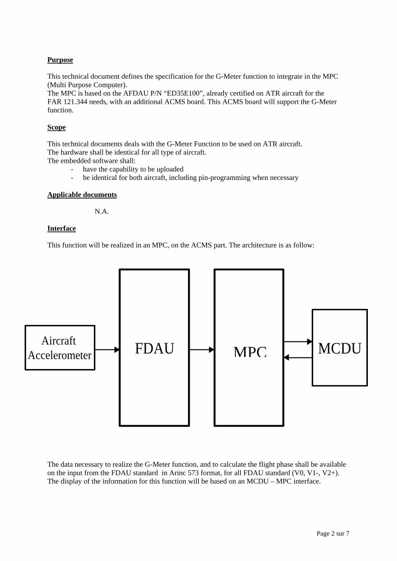
Page 2 sur 7
Purpose
This technical document defines the specification for the G-Meter function to integrate in the MPC(Multi Purpose Computer).The MPC is based on the AFDAU P/N “ED35E100”, already certified on ATR aircraft for theFAR 121.344 needs, with an additional ACMS board. This ACMS board will support the G-Meterfunction.
Scope
This technical documents deals with the G-Meter Function to be used on ATR aircraft.The hardware shall be identical for all type of aircraft.The embedded software shall:
- have the capability to be uploaded- be identical for both aircraft, including pin-programming when necessary
Applicable documents
N.A.
Interface
This function will be realized in an MPC, on the ACMS part. The architecture is as follow:
The data necessary to realize the G-Meter function, and to calculate the flight phase shall be availableon the input from the FDAU standard in Arinc 573 format, for all FDAU standard (V0, V1-, V2+).The display of the information for this function will be based on an MCDU – MPC interface.
FDAUAircraft Accelerometer AFDAU MCDU MPC
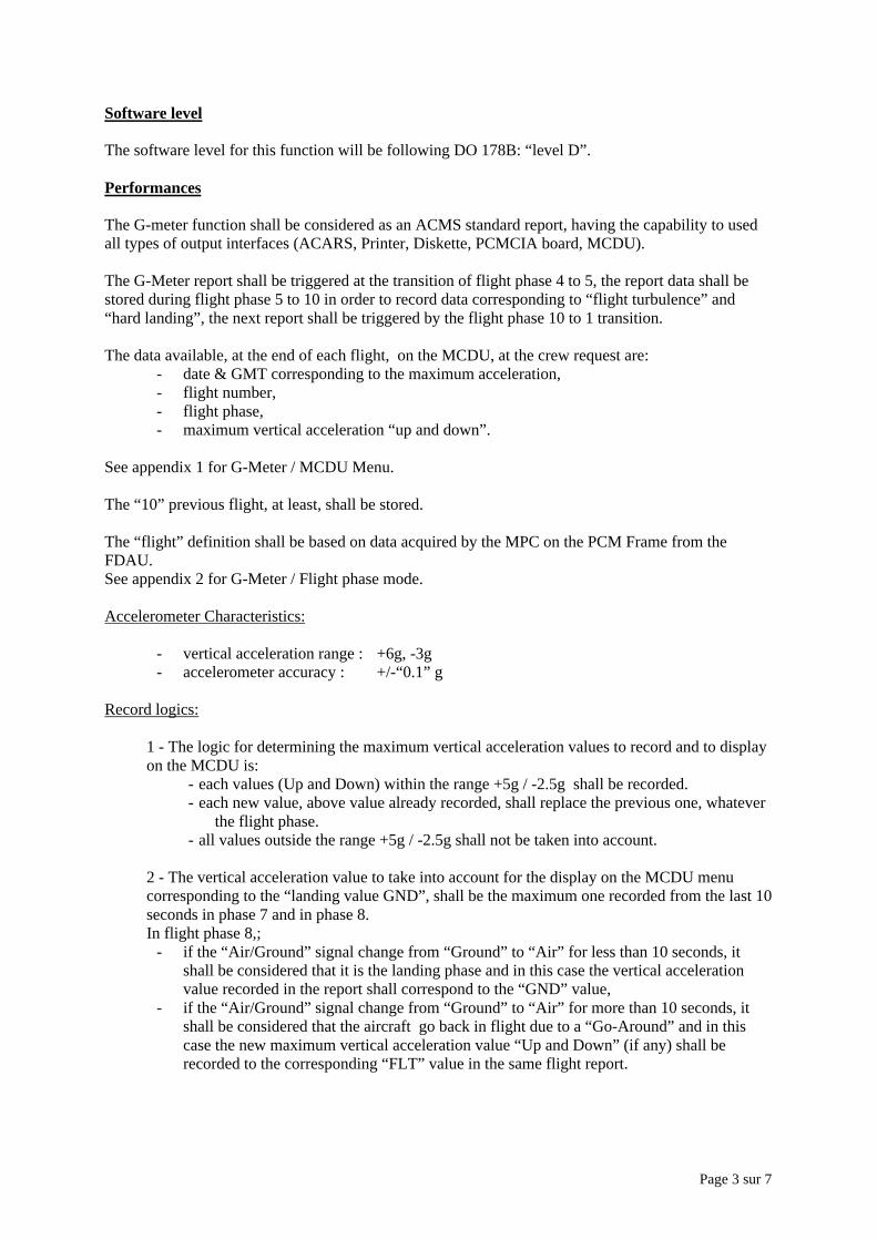
Page 3 sur 7
Software level
The software level for this function will be following DO 178B: “level D”.
Performances
The G-meter function shall be considered as an ACMS standard report, having the capability to usedall types of output interfaces (ACARS, Printer, Diskette, PCMCIA board, MCDU).
The G-Meter report shall be triggered at the transition of flight phase 4 to 5, the report data shall bestored during flight phase 5 to 10 in order to record data corresponding to “flight turbulence” and“hard landing”, the next report shall be triggered by the flight phase 10 to 1 transition.
The data available, at the end of each flight, on the MCDU, at the crew request are:- date & GMT corresponding to the maximum acceleration,- flight number,- flight phase,- maximum vertical acceleration “up and down”.
See appendix 1 for G-Meter / MCDU Menu.
The “10” previous flight, at least, shall be stored.
The “flight” definition shall be based on data acquired by the MPC on the PCM Frame from theFDAU.See appendix 2 for G-Meter / Flight phase mode.
Accelerometer Characteristics:
- vertical acceleration range : +6g, -3g- accelerometer accuracy : +/-“0.1” g
Record logics:
1 - The logic for determining the maximum vertical acceleration values to record and to displayon the MCDU is:
- each values (Up and Down) within the range +5g / -2.5g shall be recorded.- each new value, above value already recorded, shall replace the previous one, whatever
the flight phase.- all values outside the range +5g / -2.5g shall not be taken into account.
2 - The vertical acceleration value to take into account for the display on the MCDU menucorresponding to the “landing value GND”, shall be the maximum one recorded from the last 10seconds in phase 7 and in phase 8.In flight phase 8,;
- if the “Air/Ground” signal change from “Ground” to “Air” for less than 10 seconds, itshall be considered that it is the landing phase and in this case the vertical accelerationvalue recorded in the report shall correspond to the “GND” value,
- if the “Air/Ground” signal change from “Ground” to “Air” for more than 10 seconds, itshall be considered that the aircraft go back in flight due to a “Go-Around” and in thiscase the new maximum vertical acceleration value “Up and Down” (if any) shall berecorded to the corresponding “FLT” value in the same flight report.

Page 4 sur 7
Accelerometer test logic:
- At the flight phase 9 to 10 transition, on ground, the MPC shall check the validity of theaccelerometer in the 3 axis. The average values shall be computed on the 3 parametersduring 8 seconds:
- Vertical acceleration, result OK if value = 1+/- 0.2g- Lateral acceleration, result OK if value = 0+/-0.2g- Longitudinal acceleration, result OK if value = 0+/-0.2g
Result shall be presented in the G-Meter report at the end of the flight.
The menus to manage and to display this function are following description in appendix 1 .
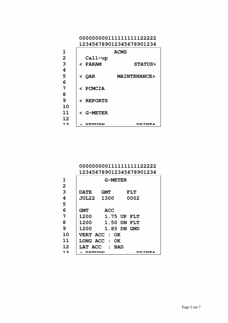
Page 5 sur 7
G-METER
DATE GMT FLTJUL22 1300 0002
GMT ACC1200 1.75 UP FLT1200 1.50 DN FLT1200 1.85 DN GNDVERT ACC : OKLONG ACC : OKLAT ACC : BAD< RETURN PRINT*
12345678910111213
000000000111111111122222123456789012345678901234
ACMS Call-up< PARAM STATUS>
< QAR MAINTENANCE>
< PCMCIA
< REPORTS
< G-METER
< RETURN PRINT*
12345678910111213
000000000111111111122222123456789012345678901234
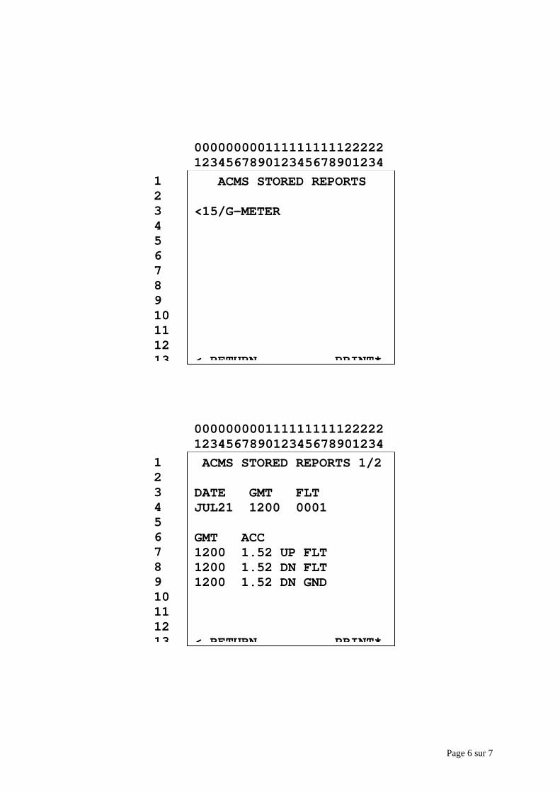
Page 6 sur 7
ACMS STORED REPORTS
<15/G-METER
< RETURN PRINT*
12345678910111213
000000000111111111122222123456789012345678901234
ACMS STORED REPORTS 1/2
DATE GMT FLT JUL21 1200 0001
GMT ACC1200 1.52 UP FLT1200 1.52 DN FLT1200 1.52 DN GND
< RETURN PRINT*
12345678910111213
000000000111111111122222123456789012345678901234
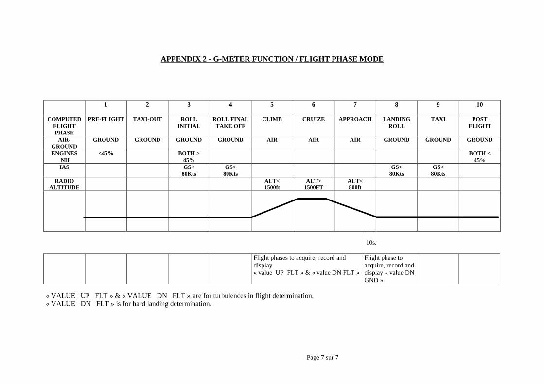
Page 7 sur 7
APPENDIX 2 - G-METER FUNCTION / FLIGHT PHASE MODE
1 2 3 4 5 6 7 8 9 10
COMPUTEDFLIGHTPHASE
PRE-FLIGHT TAXI-OUT ROLLINITIAL
ROLL FINALTAKE OFF
CLIMB CRUIZE APPROACH LANDINGROLL
TAXI POSTFLIGHT
AIR-GROUND
GROUND GROUND GROUND GROUND AIR AIR AIR GROUND GROUND GROUND
ENGINES NH
<45% BOTH >45%
BOTH <45%
IAS GS<80Kts
GS>80Kts
GS>80Kts
GS<80Kts
RADIOALTITUDE
ALT<1500ft
ALT>1500FT
ALT<800ft
10s.
Flight phases to acquire, record anddisplay« value UP FLT » & « value DN FLT »
Flight phase toacquire, record anddisplay « value DNGND »
« VALUE UP FLT » & « VALUE DN FLT » are for turbulences in flight determination,« VALUE DN FLT » is for hard landing determination.

Page 1 sur 19
PEC / EEC MAINTENANCE
SPECIFICATION
REFRENCE DO/TY 3172/04 Ed.01
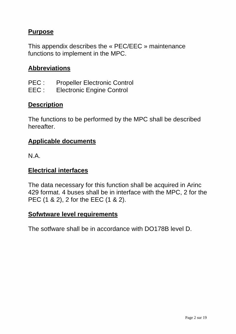
Page 2 sur 19
Purpose
This appendix describes the « PEC/EEC » maintenancefunctions to implement in the MPC.
Abbreviations
PEC : Propeller Electronic ControlEEC : Electronic Engine Control
Description
The functions to be performed by the MPC shall be describedhereafter.
Applicable documents
N.A.
Electrical interfaces
The data necessary for this function shall be acquired in Arinc429 format. 4 buses shall be in interface with the MPC, 2 for thePEC (1 & 2), 2 for the EEC (1 & 2).
Sofwtware level requirements
The sotfware shall be in accordance with DO178B level D.
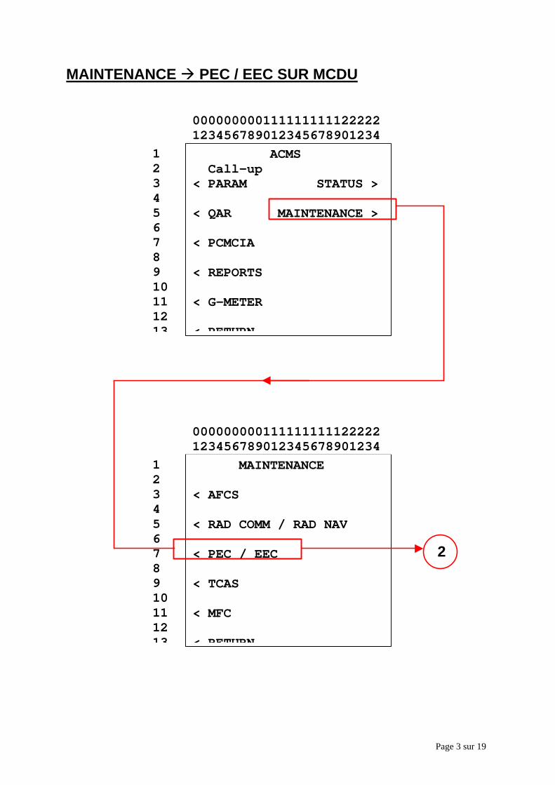
Page 3 sur 19
MAINTENANCE à PEC / EEC SUR MCDU
ACMS Call-up< PARAM STATUS > < QAR MAINTENANCE >
< PCMCIA
< REPORTS
< G-METER
< RETURN
12345678910111213
000000000111111111122222123456789012345678901234
MAINTENANCE
< AFCS
< RAD COMM / RAD NAV
< PEC / EEC
< TCAS
< MFC
< RETURN
12345678910111213
000000000111111111122222123456789012345678901234
2
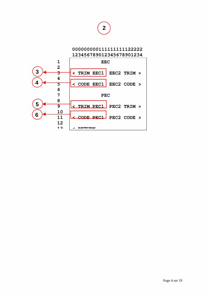
Page 4 sur 19
2
EEC
< TRIM EEC1 EEC2 TRIM >
< CODE EEC1 EEC2 CODE >
PEC
< TRIM PEC1 PEC2 TRIM >
< CODE PEC1 PEC2 CODE >
< RETURN
12345678910111213
000000000111111111122222123456789012345678901234
3
4
5
6
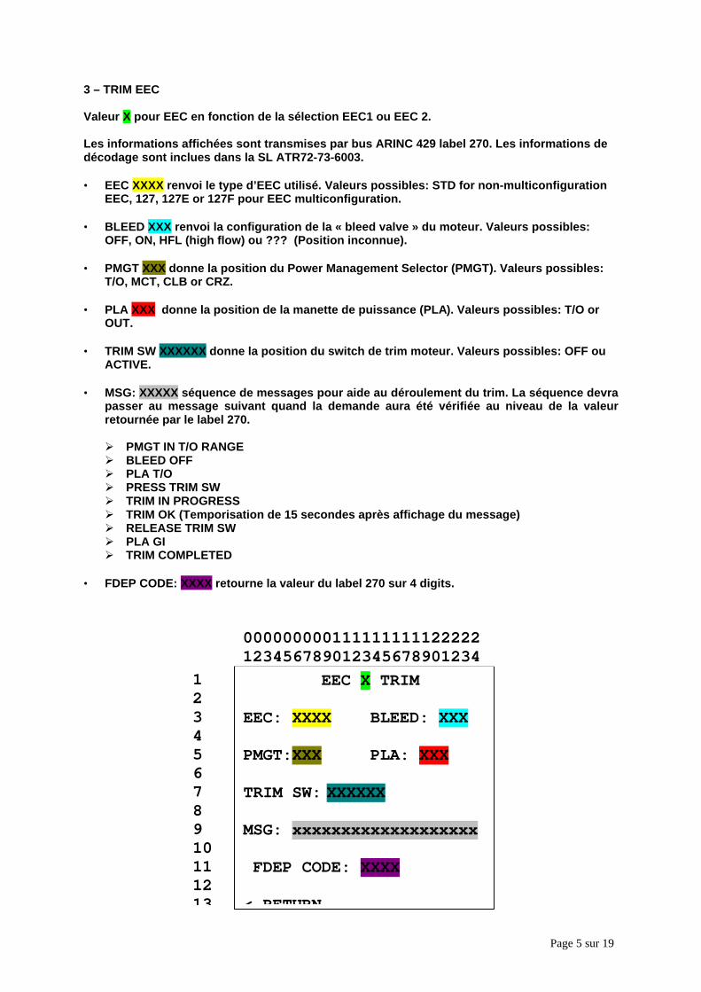
Page 5 sur 19
3 – TRIM EEC
Valeur X pour EEC en fonction de la sélection EEC1 ou EEC 2.
Les informations affichées sont transmises par bus ARINC 429 label 270. Les informations dedécodage sont inclues dans la SL ATR72-73-6003.
• EEC XXXX renvoi le type d’EEC utilisé. Valeurs possibles: STD for non-multiconfigurationEEC, 127, 127E or 127F pour EEC multiconfiguration.
• BLEED XXX renvoi la configuration de la « bleed valve » du moteur. Valeurs possibles:OFF, ON, HFL (high flow) ou ??? (Position inconnue).
• PMGT XXX donne la position du Power Management Selector (PMGT). Valeurs possibles:T/O, MCT, CLB or CRZ.
• PLA XXX donne la position de la manette de puissance (PLA). Valeurs possibles: T/O orOUT.
• TRIM SW XXXXXX donne la position du switch de trim moteur. Valeurs possibles: OFF ouACTIVE.
• MSG: XXXXX séquence de messages pour aide au déroulement du trim. La séquence devrapasser au message suivant quand la demande aura été vérifiée au niveau de la valeurretournée par le label 270.
Ø PMGT IN T/O RANGEØ BLEED OFFØ PLA T/OØ PRESS TRIM SWØ TRIM IN PROGRESSØ TRIM OK (Temporisation de 15 secondes après affichage du message)Ø RELEASE TRIM SWØ PLA GIØ TRIM COMPLETED
• FDEP CODE: XXXX retourne la valeur du label 270 sur 4 digits.
EEC X TRIM
EEC: XXXX BLEED: XXX
PMGT:XXX PLA: XXX
TRIM SW: XXXXXX
MSG: xxxxxxxxxxxxxxxxxxx
FDEP CODE: XXXX
< RETURN
12345678910111213
000000000111111111122222123456789012345678901234
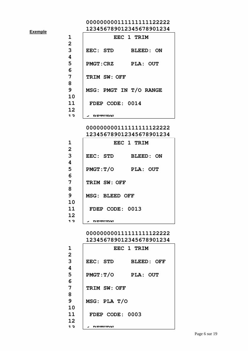
Page 6 sur 19
Exemple EEC 1 TRIM
EEC: STD BLEED: ON
PMGT:CRZ PLA: OUT
TRIM SW: OFF
MSG: PMGT IN T/O RANGE
FDEP CODE: 0014
< RETURN
12345678910111213
000000000111111111122222123456789012345678901234
EEC 1 TRIM
EEC: STD BLEED: ON
PMGT:T/O PLA: OUT
TRIM SW: OFF
MSG: BLEED OFF
FDEP CODE: 0013
< RETURN
12345678910111213
000000000111111111122222123456789012345678901234
EEC 1 TRIM
EEC: STD BLEED: OFF
PMGT:T/O PLA: OUT
TRIM SW: OFF
MSG: PLA T/O
FDEP CODE: 0003
< RETURN
12345678910111213
000000000111111111122222123456789012345678901234
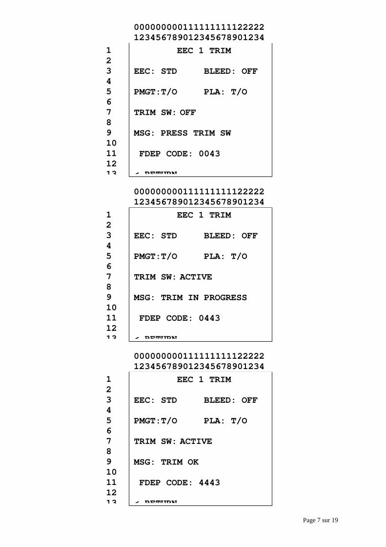
Page 7 sur 19
EEC 1 TRIM
EEC: STD BLEED: OFF
PMGT:T/O PLA: T/O
TRIM SW: OFF
MSG: PRESS TRIM SW
FDEP CODE: 0043
< RETURN
12345678910111213
000000000111111111122222123456789012345678901234
EEC 1 TRIM
EEC: STD BLEED: OFF
PMGT:T/O PLA: T/O
TRIM SW: ACTIVE
MSG: TRIM IN PROGRESS
FDEP CODE: 0443
< RETURN
12345678910111213
000000000111111111122222123456789012345678901234
EEC 1 TRIM
EEC: STD BLEED: OFF
PMGT:T/O PLA: T/O
TRIM SW: ACTIVE
MSG: TRIM OK
FDEP CODE: 4443
< RETURN
12345678910111213
000000000111111111122222123456789012345678901234
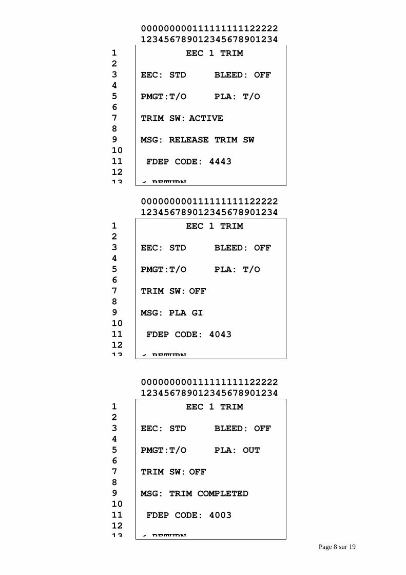
Page 8 sur 19
EEC 1 TRIM
EEC: STD BLEED: OFF
PMGT:T/O PLA: T/O
TRIM SW: ACTIVE
MSG: RELEASE TRIM SW
FDEP CODE: 4443
< RETURN
12345678910111213
000000000111111111122222123456789012345678901234
EEC 1 TRIM
EEC: STD BLEED: OFF
PMGT:T/O PLA: T/O
TRIM SW: OFF
MSG: PLA GI
FDEP CODE: 4043
< RETURN
12345678910111213
000000000111111111122222123456789012345678901234
EEC 1 TRIM
EEC: STD BLEED: OFF
PMGT:T/O PLA: OUT
TRIM SW: OFF
MSG: TRIM COMPLETED
FDEP CODE: 4003
< RETURN
12345678910111213
000000000111111111122222123456789012345678901234
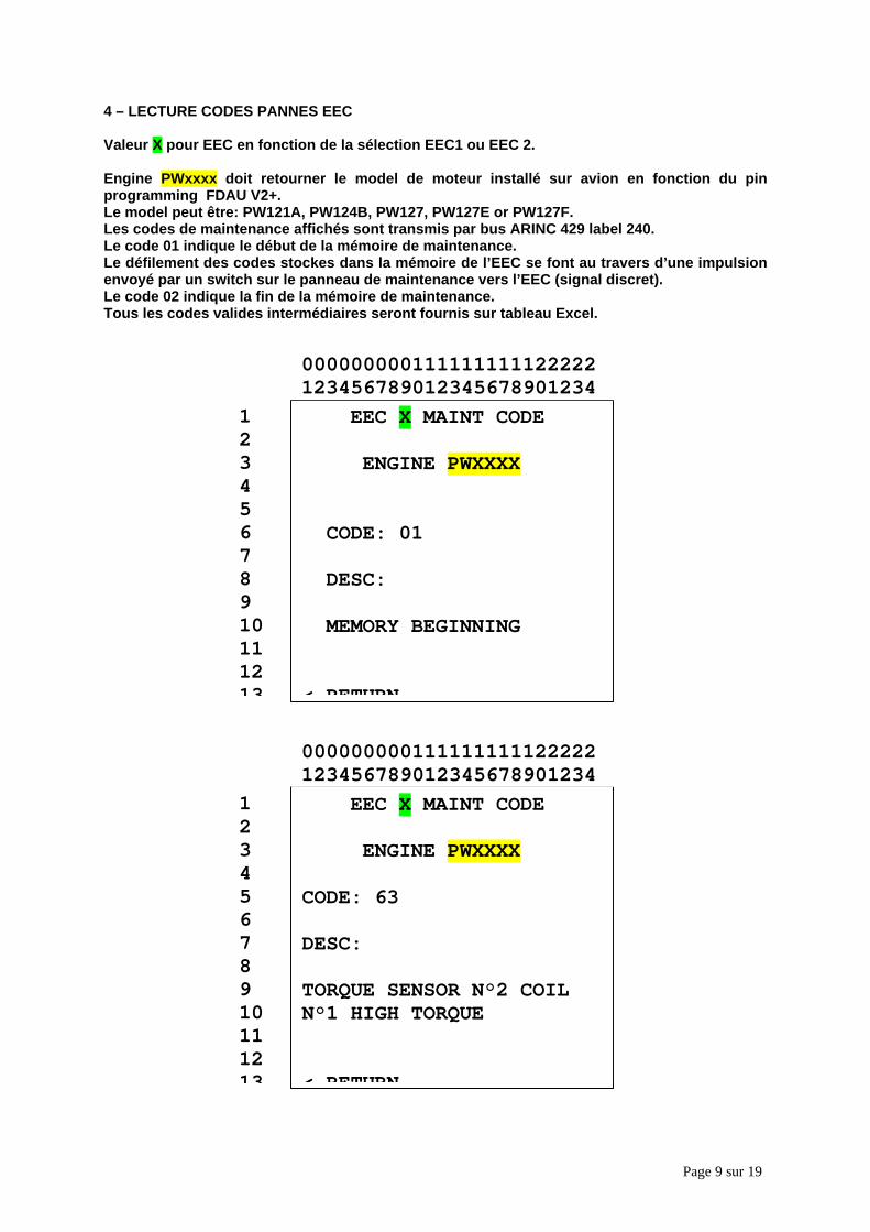
Page 9 sur 19
4 – LECTURE CODES PANNES EEC
Valeur X pour EEC en fonction de la sélection EEC1 ou EEC 2.
Engine PWxxxx doit retourner le model de moteur installé sur avion en fonction du pinprogramming FDAU V2+.Le model peut être: PW121A, PW124B, PW127, PW127E or PW127F.Les codes de maintenance affichés sont transmis par bus ARINC 429 label 240.Le code 01 indique le début de la mémoire de maintenance.Le défilement des codes stockes dans la mémoire de l’EEC se font au travers d’une impulsionenvoyé par un switch sur le panneau de maintenance vers l’EEC (signal discret).Le code 02 indique la fin de la mémoire de maintenance.Tous les codes valides intermédiaires seront fournis sur tableau Excel.
EEC X MAINT CODE
ENGINE PWXXXX
CODE: 01
DESC:
MEMORY BEGINNING
< RETURN
12345678910111213
000000000111111111122222123456789012345678901234
EEC X MAINT CODE
ENGINE PWXXXX
CODE: 63
DESC:
TORQUE SENSOR N°2 COILN°1 HIGH TORQUE
< RETURN
12345678910111213
000000000111111111122222123456789012345678901234
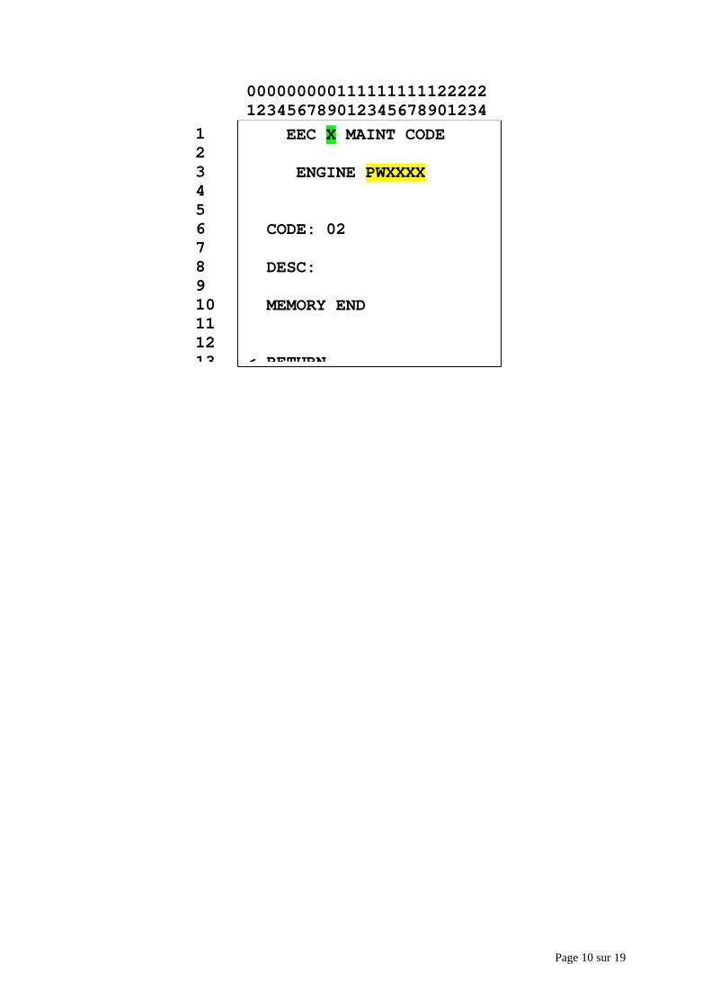
Page 10 sur 19
EEC X MAINT CODE
ENGINE PWXXXX
CODE: 02
DESC:
MEMORY END
< RETURN
12345678910111213
000000000111111111122222123456789012345678901234
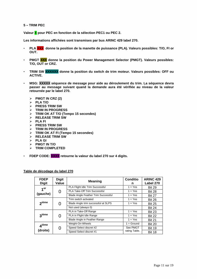
Page 11 sur 19
5 – TRIM PEC
Valeur X pour PEC en fonction de la sélection PEC1 ou PEC 2.
Les informations affichées sont transmises par bus ARINC 429 label 270.
• PLA XXX donne la position de la manette de puissance (PLA). Valeurs possibles: T/O, FI orOUT.
• PMGT XXX donne la position du Power Management Selector (PMGT). Valeurs possibles:T/O, OUT or CRZ.
• TRIM SW XXXXXX donne la position du switch de trim moteur. Valeurs possibles: OFF ouACTIVE.
• MSG: XXXXX séquence de message pour aide au déroulement du trim. La séquence devrapasser au message suivant quand la demande aura été vérifiée au niveau de la valeurretournée par le label 270.
Ø PMGT IN CRZ (2)Ø PLA T/OØ PRESS TRIM SWØ TRIM IN PROGRESSØ TRIM OK AT T/O (Tempo 15 secondes)Ø RELEASE TRIM SWØ PLA FIØ PRESS TRIM SWØ TRIM IN PROGRESSØ TRIM OK AT FI (Tempo 15 secondes)Ø RELEASE TRIM SWØ PLA GIØ PMGT IN T/OØ TRIM COMPLETED
• FDEP CODE: XXXX retourne la valeur du label 270 sur 4 digits.
Table de décodage du label 270
FDEPDigit
DigitValue Meaning Conditio
nARINC 429Label 270
PLA Flight Idle Trim Successful 1 = Yes Bit 29PLA Take-Off Trim Successful 1 = Yes Bit 281er
(gauche) 0Blade Angle Feather Trim Successful 1 = Yes Bit 27Trim switch activated 1 = Yes Bit 26Blade Angle trim successful at SLPS 1 = Yes Bit 252ième 0Not used (always 0) Bit 24PLA in Take-Off Range 1 = Yes Bit 23PLA in Flight Idle Range 1 = Yes Bit 223ième 0Blade Angle in Feather Range 1 = Yes Bit 21Weight-On-Wheels 1 = Ground Bit 20Speed Select discret #2 Bit 194ième
(droite) 0Speed Select discret #1
See PMGTrating Table. Bit 18
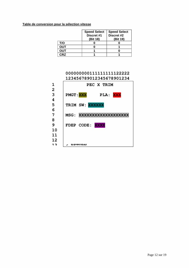
Page 12 sur 19
Table de conversion pour la sélection vitesse
Speed SelectDiscret #1
(Bit 18)
Speed SelectDiscret #2
(Bit 19)T/O 0 0OUT 0 1OUT 1 0CRZ 1 1
PEC X TRIM
PMGT:XXX PLA: XXX
TRIM SW: XXXXXX
MSG: XXXXXXXXXXXXXXXXXXX
FDEP CODE: XXXX
< RETURN
12345678910111213
000000000111111111122222123456789012345678901234
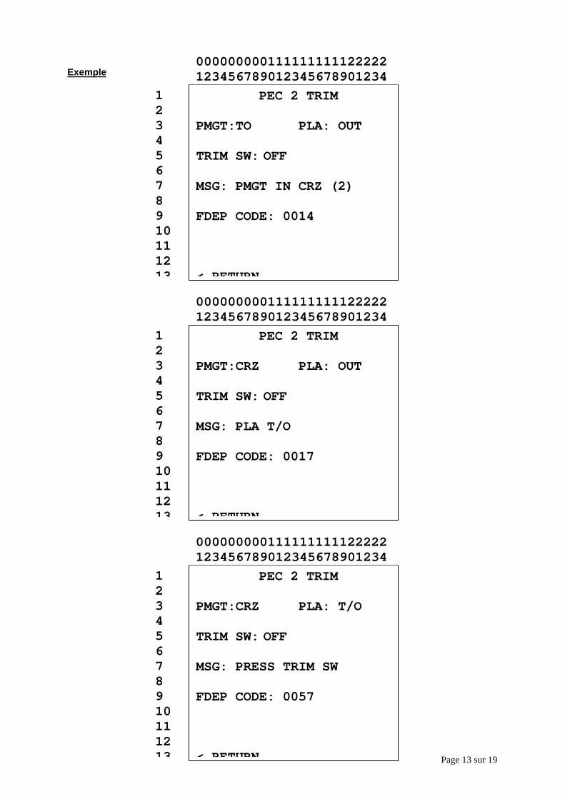
Page 13 sur 19
Exemple
PEC 2 TRIM
PMGT:TO PLA: OUT
TRIM SW: OFF
MSG: PMGT IN CRZ (2)
FDEP CODE: 0014
< RETURN
12345678910111213
000000000111111111122222123456789012345678901234
PEC 2 TRIM
PMGT:CRZ PLA: OUT
TRIM SW: OFF
MSG: PLA T/O
FDEP CODE: 0017
< RETURN
12345678910111213
000000000111111111122222123456789012345678901234
PEC 2 TRIM
PMGT:CRZ PLA: T/O
TRIM SW: OFF
MSG: PRESS TRIM SW
FDEP CODE: 0057
< RETURN
12345678910111213
000000000111111111122222123456789012345678901234
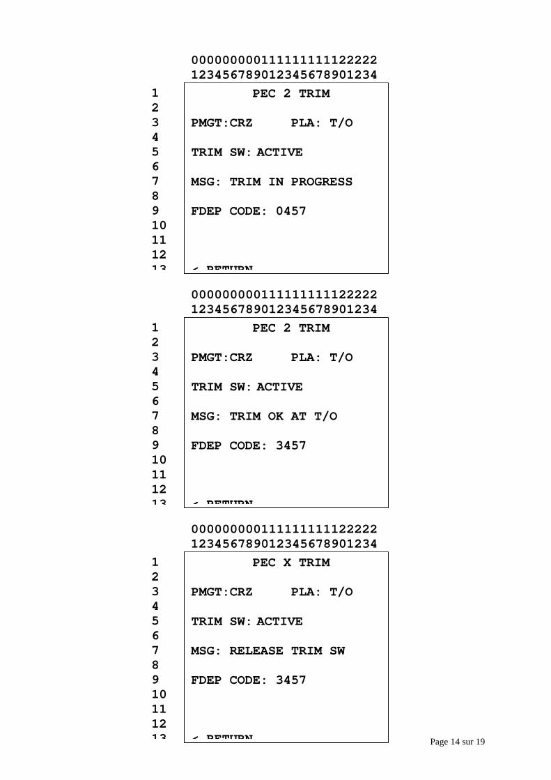
Page 14 sur 19
PEC 2 TRIM
PMGT:CRZ PLA: T/O
TRIM SW: ACTIVE
MSG: TRIM IN PROGRESS
FDEP CODE: 0457
< RETURN
12345678910111213
000000000111111111122222123456789012345678901234
PEC 2 TRIM
PMGT:CRZ PLA: T/O
TRIM SW: ACTIVE
MSG: TRIM OK AT T/O
FDEP CODE: 3457
< RETURN
12345678910111213
000000000111111111122222123456789012345678901234
PEC X TRIM
PMGT:CRZ PLA: T/O
TRIM SW: ACTIVE
MSG: RELEASE TRIM SW
FDEP CODE: 3457
< RETURN
12345678910111213
000000000111111111122222123456789012345678901234
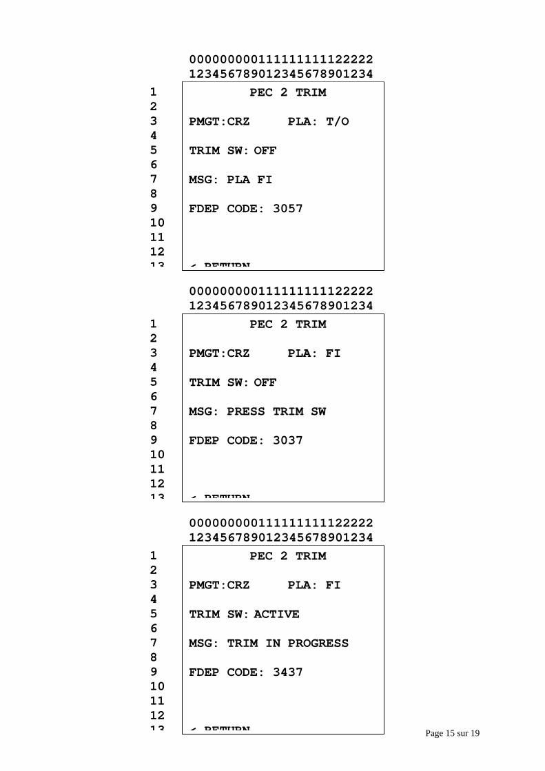
Page 15 sur 19
PEC 2 TRIM
PMGT:CRZ PLA: T/O
TRIM SW: OFF
MSG: PLA FI
FDEP CODE: 3057
< RETURN
12345678910111213
000000000111111111122222123456789012345678901234
PEC 2 TRIM
PMGT:CRZ PLA: FI
TRIM SW: OFF
MSG: PRESS TRIM SW
FDEP CODE: 3037
< RETURN
12345678910111213
000000000111111111122222123456789012345678901234
PEC 2 TRIM
PMGT:CRZ PLA: FI
TRIM SW: ACTIVE
MSG: TRIM IN PROGRESS
FDEP CODE: 3437
< RETURN
12345678910111213
000000000111111111122222123456789012345678901234
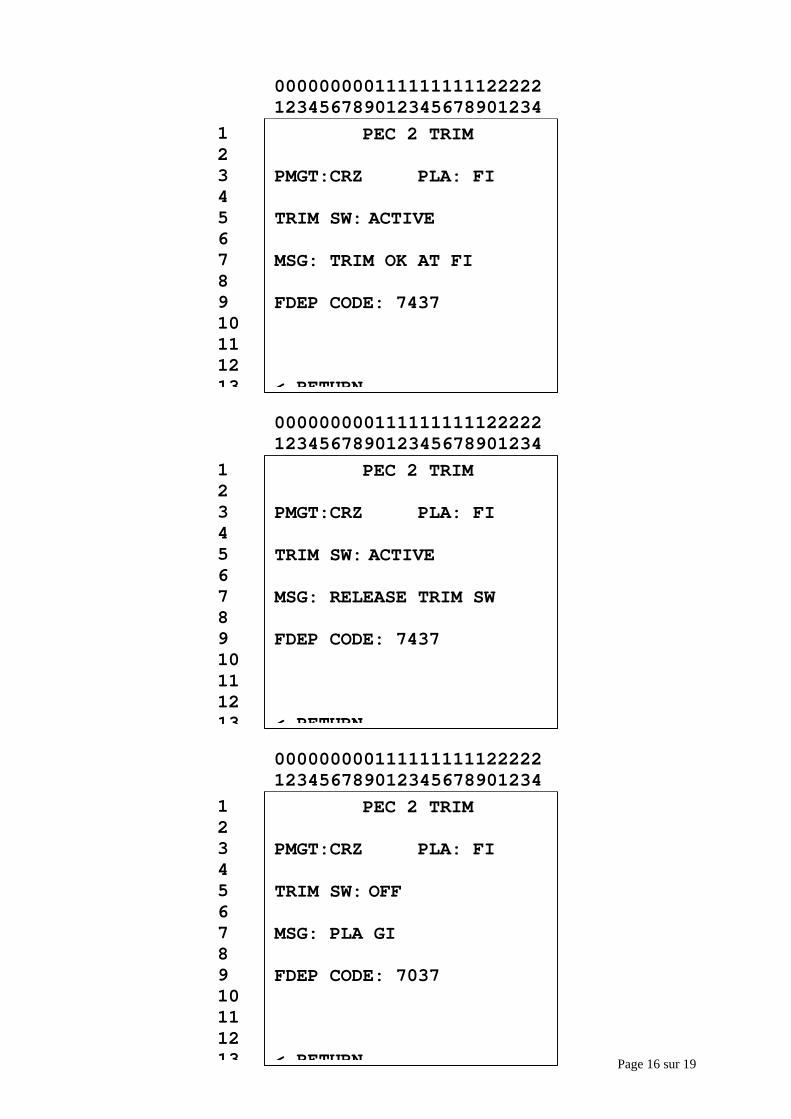
Page 16 sur 19
PEC 2 TRIM
PMGT:CRZ PLA: FI
TRIM SW: ACTIVE
MSG: TRIM OK AT FI
FDEP CODE: 7437
< RETURN
12345678910111213
000000000111111111122222123456789012345678901234
PEC 2 TRIM
PMGT:CRZ PLA: FI
TRIM SW: ACTIVE
MSG: RELEASE TRIM SW
FDEP CODE: 7437
< RETURN
12345678910111213
000000000111111111122222123456789012345678901234
PEC 2 TRIM
PMGT:CRZ PLA: FI
TRIM SW: OFF
MSG: PLA GI
FDEP CODE: 7037
< RETURN
12345678910111213
000000000111111111122222123456789012345678901234
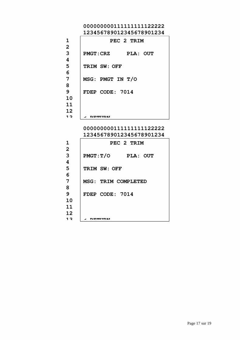
Page 17 sur 19
PEC 2 TRIM
PMGT:CRZ PLA: OUT
TRIM SW: OFF
MSG: PMGT IN T/O
FDEP CODE: 7014
< RETURN
12345678910111213
000000000111111111122222123456789012345678901234
PEC 2 TRIM
PMGT:T/O PLA: OUT
TRIM SW: OFF
MSG: TRIM COMPLETED
FDEP CODE: 7014
< RETURN
12345678910111213
000000000111111111122222123456789012345678901234
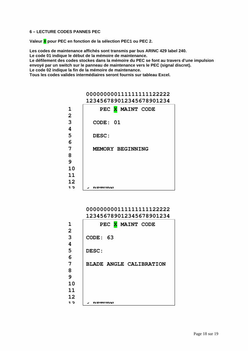
Page 18 sur 19
6 – LECTURE CODES PANNES PEC
Valeur X pour PEC en fonction de la sélection PEC1 ou PEC 2.
Les codes de maintenance affichés sont transmis par bus ARINC 429 label 240.Le code 01 indique le début de la mémoire de maintenance.Le défilement des codes stockes dans la mémoire du PEC se font au travers d’une impulsionenvoyé par un switch sur le panneau de maintenance vers le PEC (signal discret).Le code 02 indique la fin de la mémoire de maintenance.Tous les codes valides intermédiaires seront fournis sur tableau Excel.
PEC X MAINT CODE
CODE: 63
DESC:
BLADE ANGLE CALIBRATION
< RETURN
12345678910111213
000000000111111111122222123456789012345678901234
PEC X MAINT CODE
CODE: 01
DESC:
MEMORY BEGINNING
< RETURN
12345678910111213
000000000111111111122222123456789012345678901234
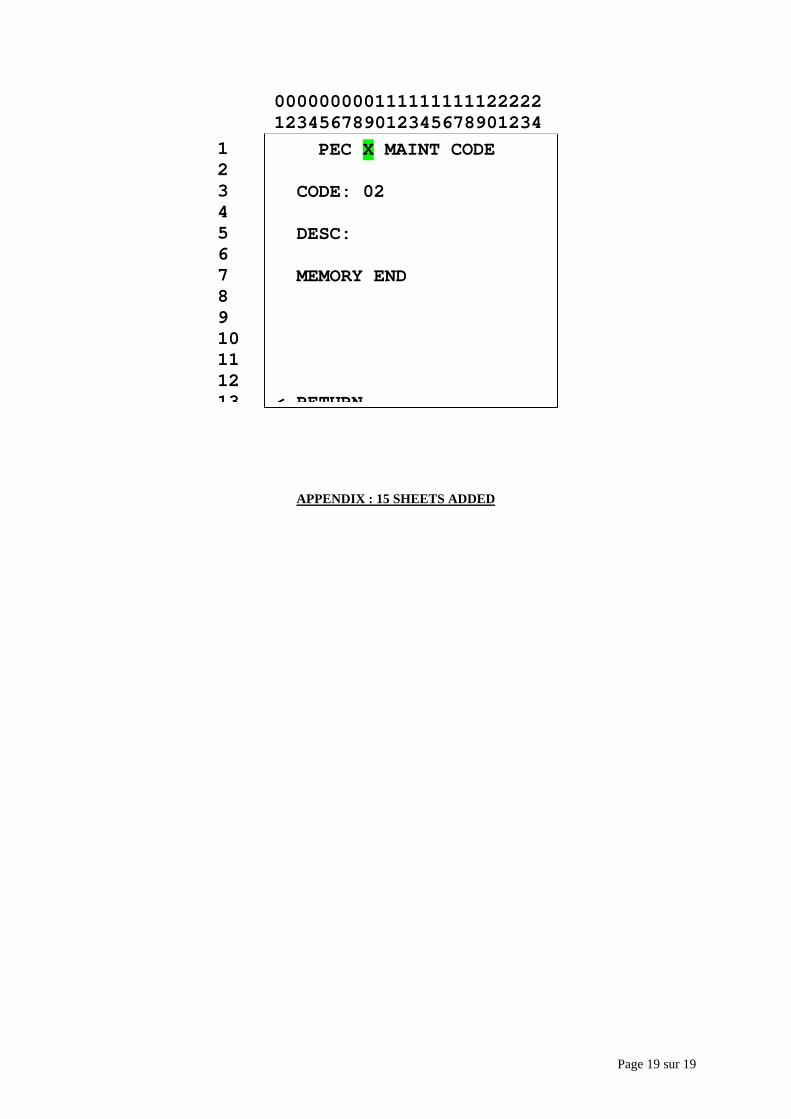
Page 19 sur 19
APPENDIX : 15 SHEETS ADDED
PEC X MAINT CODE
CODE: 02
DESC:
MEMORY END
< RETURN
12345678910111213
000000000111111111122222123456789012345678901234
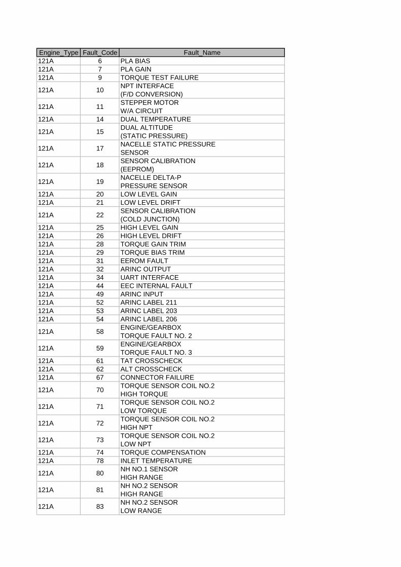
Engine_Type Fault_Code Fault_Name121A 6 PLA BIAS121A 7 PLA GAIN121A 9 TORQUE TEST FAILURE
121A 10NPT INTERFACE(F/D CONVERSION)
121A 11STEPPER MOTORW/A CIRCUIT
121A 14 DUAL TEMPERATURE
121A 15DUAL ALTITUDE(STATIC PRESSURE)
121A 17NACELLE STATIC PRESSURESENSOR
121A 18SENSOR CALIBRATION(EEPROM)
121A 19NACELLE DELTA-PPRESSURE SENSOR
121A 20 LOW LEVEL GAIN121A 21 LOW LEVEL DRIFT
121A 22SENSOR CALIBRATION(COLD JUNCTION)
121A 25 HIGH LEVEL GAIN121A 26 HIGH LEVEL DRIFT121A 28 TORQUE GAIN TRIM121A 29 TORQUE BIAS TRIM121A 31 EEROM FAULT121A 32 ARINC OUTPUT121A 34 UART INTERFACE121A 44 EEC INTERNAL FAULT121A 49 ARINC INPUT121A 52 ARINC LABEL 211121A 53 ARINC LABEL 203121A 54 ARINC LABEL 206
121A 58ENGINE/GEARBOXTORQUE FAULT NO. 2
121A 59ENGINE/GEARBOXTORQUE FAULT NO. 3
121A 61 TAT CROSSCHECK121A 62 ALT CROSSCHECK121A 67 CONNECTOR FAILURE
121A 70TORQUE SENSOR COIL NO.2HIGH TORQUE
121A 71TORQUE SENSOR COIL NO.2LOW TORQUE
121A 72TORQUE SENSOR COIL NO.2HIGH NPT
121A 73TORQUE SENSOR COIL NO.2LOW NPT
121A 74 TORQUE COMPENSATION121A 78 INLET TEMPERATURE
121A 80NH NO.1 SENSORHIGH RANGE
121A 81NH NO.2 SENSORHIGH RANGE
121A 83NH NO.2 SENSORLOW RANGE
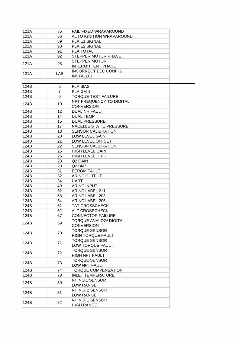
121A 85 FAIL FIXED WRAPAROUND121A 86 AUTO IGNITION WRAPAROUND121A 89 PLA E1 SIGNAL121A 90 PLA E2 SIGNAL121A 91 PLA TOTAL121A 92 STEPPER MOTOR PHASE
121A 93STEPPER MOTORINTERMITTENT PHASE
121A LABINCORRECT EEC CONFIG.INSTALLED
124B 6 PLA BIAS124B 7 PLA GAIN124B 9 TORQUE TEST FAILURE
124B 10NPT FREQUENCY TO DIGITALCONVERSION
124B 12 DUAL NH FAULT124B 14 DUAL TEMP124B 15 DUAL PRESSURE124B 17 NACELLE STATIC PRESSURE124B 18 SENSOR CALIBRATION124B 20 LOW LEVEL GAIN124B 21 LOW LEVEL OFFSET124B 22 SENSOR CALIBRATION124B 25 HIGH LEVEL GAIN124B 26 HIGH LEVEL DRIFT124B 28 Q2 GAIN124B 29 Q2 BIAS124B 31 EEROM FAULT124B 32 ARINC OUTPUT124B 34 UART124B 49 ARINC INPUT124B 52 ARINC LABEL 211124B 53 ARINC LABEL 203124B 54 ARINC LABEL 206124B 61 TAT CROSSCHECK124B 62 ALT CROSSCHECK124B 67 CONNECTOR FAILURE
124B 69TORQUE ANALOG/ DIGITALCONVERSION
124B 70TORQUE SENSORHIGH TORQUE FAULT
124B 71TORQUE SENSORLOW TORQUE FAULT
124B 72TORQUE SENSORHIGH NPT FAULT
124B 73TORQUE SENSORLOW NPT FAULT
124B 74 TORQUE COMPENSATION124B 78 INLET TEMPERATURE
124B 80NH NO.1 SENSORLOW RANGE
124B 81NH NO. 2 SENSORLOW RANGE
124B 82NH NO. 1 SENSORHIGH RANGE
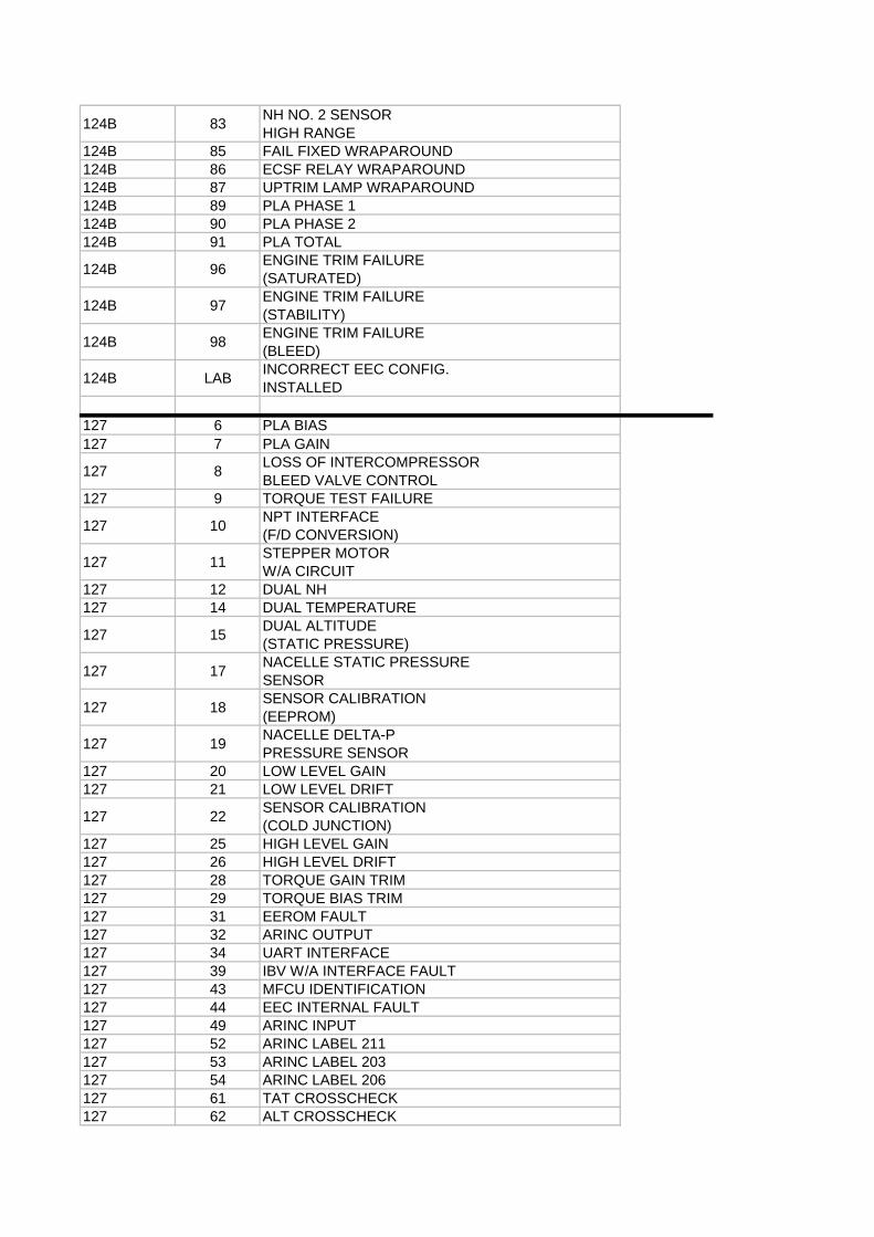
124B 83NH NO. 2 SENSORHIGH RANGE
124B 85 FAIL FIXED WRAPAROUND124B 86 ECSF RELAY WRAPAROUND124B 87 UPTRIM LAMP WRAPAROUND124B 89 PLA PHASE 1124B 90 PLA PHASE 2124B 91 PLA TOTAL
124B 96ENGINE TRIM FAILURE(SATURATED)
124B 97ENGINE TRIM FAILURE(STABILITY)
124B 98ENGINE TRIM FAILURE(BLEED)
124B LABINCORRECT EEC CONFIG.INSTALLED
127 6 PLA BIAS127 7 PLA GAIN
127 8LOSS OF INTERCOMPRESSORBLEED VALVE CONTROL
127 9 TORQUE TEST FAILURE
127 10NPT INTERFACE(F/D CONVERSION)
127 11STEPPER MOTORW/A CIRCUIT
127 12 DUAL NH127 14 DUAL TEMPERATURE
127 15DUAL ALTITUDE(STATIC PRESSURE)
127 17NACELLE STATIC PRESSURESENSOR
127 18SENSOR CALIBRATION(EEPROM)
127 19NACELLE DELTA-PPRESSURE SENSOR
127 20 LOW LEVEL GAIN127 21 LOW LEVEL DRIFT
127 22SENSOR CALIBRATION(COLD JUNCTION)
127 25 HIGH LEVEL GAIN127 26 HIGH LEVEL DRIFT127 28 TORQUE GAIN TRIM127 29 TORQUE BIAS TRIM127 31 EEROM FAULT127 32 ARINC OUTPUT127 34 UART INTERFACE127 39 IBV W/A INTERFACE FAULT127 43 MFCU IDENTIFICATION127 44 EEC INTERNAL FAULT127 49 ARINC INPUT127 52 ARINC LABEL 211127 53 ARINC LABEL 203127 54 ARINC LABEL 206127 61 TAT CROSSCHECK127 62 ALT CROSSCHECK
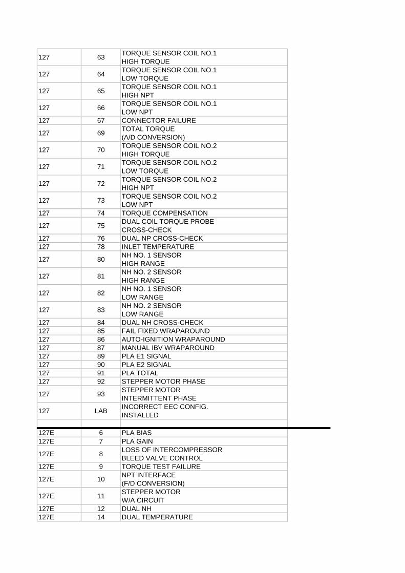
127 63TORQUE SENSOR COIL NO.1HIGH TORQUE
127 64TORQUE SENSOR COIL NO.1LOW TORQUE
127 65TORQUE SENSOR COIL NO.1HIGH NPT
127 66TORQUE SENSOR COIL NO.1LOW NPT
127 67 CONNECTOR FAILURE
127 69TOTAL TORQUE(A/D CONVERSION)
127 70TORQUE SENSOR COIL NO.2HIGH TORQUE
127 71TORQUE SENSOR COIL NO.2LOW TORQUE
127 72TORQUE SENSOR COIL NO.2HIGH NPT
127 73TORQUE SENSOR COIL NO.2LOW NPT
127 74 TORQUE COMPENSATION
127 75DUAL COIL TORQUE PROBECROSS-CHECK
127 76 DUAL NP CROSS-CHECK127 78 INLET TEMPERATURE
127 80NH NO. 1 SENSORHIGH RANGE
127 81NH NO. 2 SENSORHIGH RANGE
127 82NH NO. 1 SENSORLOW RANGE
127 83NH NO. 2 SENSORLOW RANGE
127 84 DUAL NH CROSS-CHECK127 85 FAIL FIXED WRAPAROUND127 86 AUTO-IGNITION WRAPAROUND127 87 MANUAL IBV WRAPAROUND127 89 PLA E1 SIGNAL127 90 PLA E2 SIGNAL127 91 PLA TOTAL127 92 STEPPER MOTOR PHASE
127 93STEPPER MOTORINTERMITTENT PHASE
127 LABINCORRECT EEC CONFIG.INSTALLED
127E 6 PLA BIAS127E 7 PLA GAIN
127E 8LOSS OF INTERCOMPRESSORBLEED VALVE CONTROL
127E 9 TORQUE TEST FAILURE
127E 10NPT INTERFACE(F/D CONVERSION)
127E 11STEPPER MOTORW/A CIRCUIT
127E 12 DUAL NH127E 14 DUAL TEMPERATURE
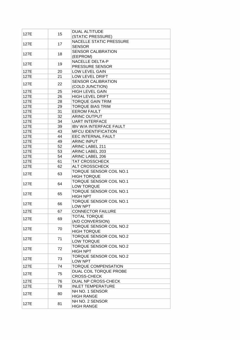
127E 15DUAL ALTITUDE(STATIC PRESSURE)
127E 17NACELLE STATIC PRESSURESENSOR
127E 18SENSOR CALIBRATION(EEPROM)
127E 19NACELLE DELTA-PPRESSURE SENSOR
127E 20 LOW LEVEL GAIN127E 21 LOW LEVEL DRIFT
127E 22SENSOR CALIBRATION(COLD JUNCTION)
127E 25 HIGH LEVEL GAIN127E 26 HIGH LEVEL DRIFT127E 28 TORQUE GAIN TRIM127E 29 TORQUE BIAS TRIM127E 31 EEROM FAULT127E 32 ARINC OUTPUT127E 34 UART INTERFACE127E 39 IBV W/A INTERFACE FAULT127E 43 MFCU IDENTIFICATION127E 44 EEC INTERNAL FAULT127E 49 ARINC INPUT127E 52 ARINC LABEL 211127E 53 ARINC LABEL 203127E 54 ARINC LABEL 206127E 61 TAT CROSSCHECK127E 62 ALT CROSSCHECK
127E 63TORQUE SENSOR COIL NO.1HIGH TORQUE
127E 64TORQUE SENSOR COIL NO.1LOW TORQUE
127E 65TORQUE SENSOR COIL NO.1HIGH NPT
127E 66TORQUE SENSOR COIL NO.1LOW NPT
127E 67 CONNECTOR FAILURE
127E 69TOTAL TORQUE(A/D CONVERSION)
127E 70TORQUE SENSOR COIL NO.2HIGH TORQUE
127E 71TORQUE SENSOR COIL NO.2LOW TORQUE
127E 72TORQUE SENSOR COIL NO.2HIGH NPT
127E 73TORQUE SENSOR COIL NO.2LOW NPT
127E 74 TORQUE COMPENSATION
127E 75DUAL COIL TORQUE PROBECROSS-CHECK
127E 76 DUAL NP CROSS-CHECK127E 78 INLET TEMPERATURE
127E 80NH NO. 1 SENSORHIGH RANGE
127E 81NH NO. 2 SENSORHIGH RANGE
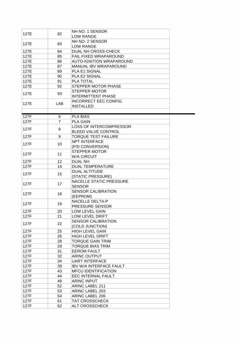
127E 82NH NO. 1 SENSORLOW RANGE
127E 83NH NO. 2 SENSORLOW RANGE
127E 84 DUAL NH CROSS-CHECK127E 85 FAIL FIXED WRAPAROUND127E 86 AUTO-IGNITION WRAPAROUND127E 87 MANUAL IBV WRAPAROUND127E 89 PLA E1 SIGNAL127E 90 PLA E2 SIGNAL127E 91 PLA TOTAL127E 92 STEPPER MOTOR PHASE
127E 93STEPPER MOTORINTERMITTENT PHASE
127E LABINCORRECT EEC CONFIG.INSTALLED
127F 6 PLA BIAS127F 7 PLA GAIN
127F 8LOSS OF INTERCOMPRESSORBLEED VALVE CONTROL
127F 9 TORQUE TEST FAILURE
127F 10NPT INTERFACE(F/D CONVERSION)
127F 11STEPPER MOTORW/A CIRCUIT
127F 12 DUAL NH127F 14 DUAL TEMPERATURE
127F 15DUAL ALTITUDE(STATIC PRESSURE)
127F 17NACELLE STATIC PRESSURESENSOR
127F 18SENSOR CALIBRATION(EEPROM)
127F 19NACELLE DELTA-PPRESSURE SENSOR
127F 20 LOW LEVEL GAIN127F 21 LOW LEVEL DRIFT
127F 22SENSOR CALIBRATION(COLD JUNCTION)
127F 25 HIGH LEVEL GAIN127F 26 HIGH LEVEL DRIFT127F 28 TORQUE GAIN TRIM127F 29 TORQUE BIAS TRIM127F 31 EEROM FAULT127F 32 ARINC OUTPUT127F 34 UART INTERFACE127F 39 IBV W/A INTERFACE FAULT127F 43 MFCU IDENTIFICATION127F 44 EEC INTERNAL FAULT127F 49 ARINC INPUT127F 52 ARINC LABEL 211127F 53 ARINC LABEL 203127F 54 ARINC LABEL 206127F 61 TAT CROSSCHECK127F 62 ALT CROSSCHECK
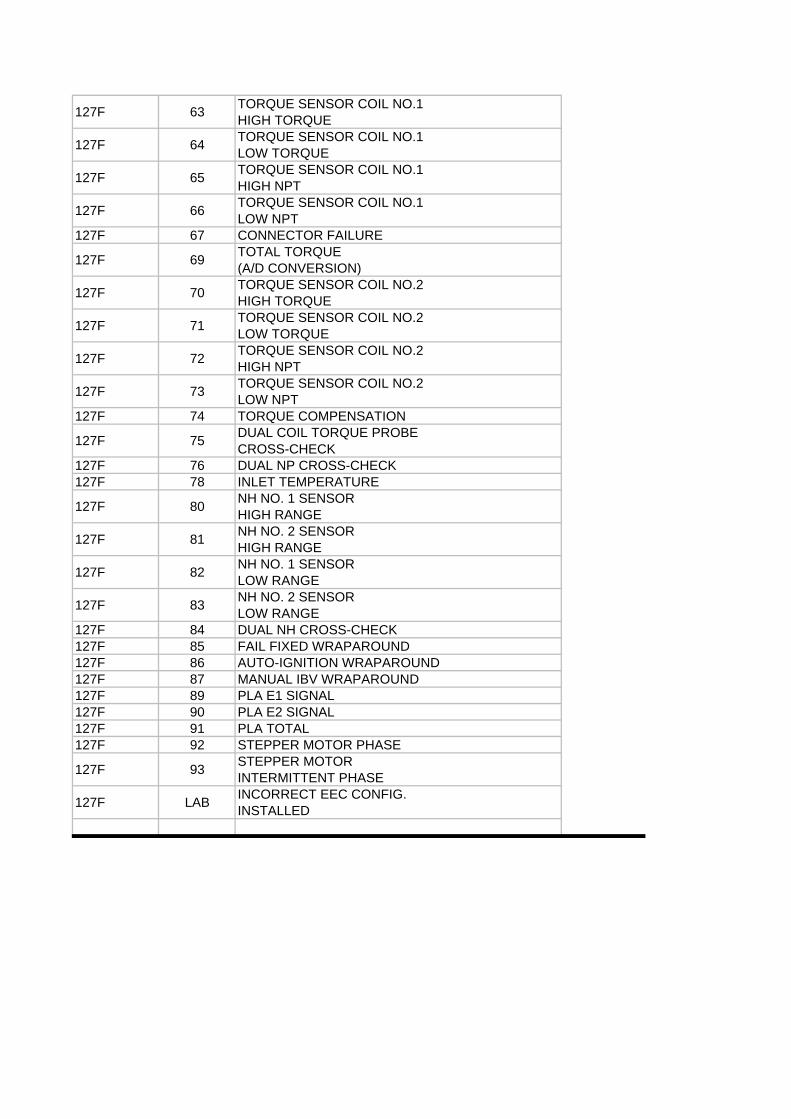
127F 63TORQUE SENSOR COIL NO.1HIGH TORQUE
127F 64TORQUE SENSOR COIL NO.1LOW TORQUE
127F 65TORQUE SENSOR COIL NO.1HIGH NPT
127F 66TORQUE SENSOR COIL NO.1LOW NPT
127F 67 CONNECTOR FAILURE
127F 69TOTAL TORQUE(A/D CONVERSION)
127F 70TORQUE SENSOR COIL NO.2HIGH TORQUE
127F 71TORQUE SENSOR COIL NO.2LOW TORQUE
127F 72TORQUE SENSOR COIL NO.2HIGH NPT
127F 73TORQUE SENSOR COIL NO.2LOW NPT
127F 74 TORQUE COMPENSATION
127F 75DUAL COIL TORQUE PROBECROSS-CHECK
127F 76 DUAL NP CROSS-CHECK127F 78 INLET TEMPERATURE
127F 80NH NO. 1 SENSORHIGH RANGE
127F 81NH NO. 2 SENSORHIGH RANGE
127F 82NH NO. 1 SENSORLOW RANGE
127F 83NH NO. 2 SENSORLOW RANGE
127F 84 DUAL NH CROSS-CHECK127F 85 FAIL FIXED WRAPAROUND127F 86 AUTO-IGNITION WRAPAROUND127F 87 MANUAL IBV WRAPAROUND127F 89 PLA E1 SIGNAL127F 90 PLA E2 SIGNAL127F 91 PLA TOTAL127F 92 STEPPER MOTOR PHASE
127F 93STEPPER MOTORINTERMITTENT PHASE
127F LABINCORRECT EEC CONFIG.INSTALLED
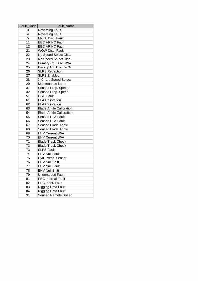
Fault_Code Fault_Name3 Reversing Fault4 Reversing Fault5 Maint. Disc. Fault11 EEC ARINC Fault12 EEC ARINC Fault21 WOW Disc. Fault22 Np Speed Select Disc.23 Np Speed Select Disc.24 Primary Ch. Disc. W/A25 Backup Ch. Disc. W/A26 SLPS Retraction27 SLPS Enabled28 X-Chan. Speed Select29 Maintenance Lamp31 Sensed Prop. Speed32 Sensed Prop. Speed51 OSG Fault61 PLA Calibration62 PLA Calibration63 Blade Angle Calibration64 Blade Angle Calibration65 Sensed PLA Fault66 Sensed PLA Fault67 Sensed Blade Angle68 Sensed Blade Angle69 EHV Current W/A70 EHV Current W/A71 Blade Track Check72 Blade Track Check73 SLPS Fault74 EHV Null Fault75 Hyd. Press. Sensor76 EHV Null Shift77 EHV Null Fault78 EHV Null Shift79 Underspeed Fault81 PEC Internal Fault82 PEC Ident. Fault83 Rigging Data Fault84 Rigging Data Fault91 Sensed Remote Speed
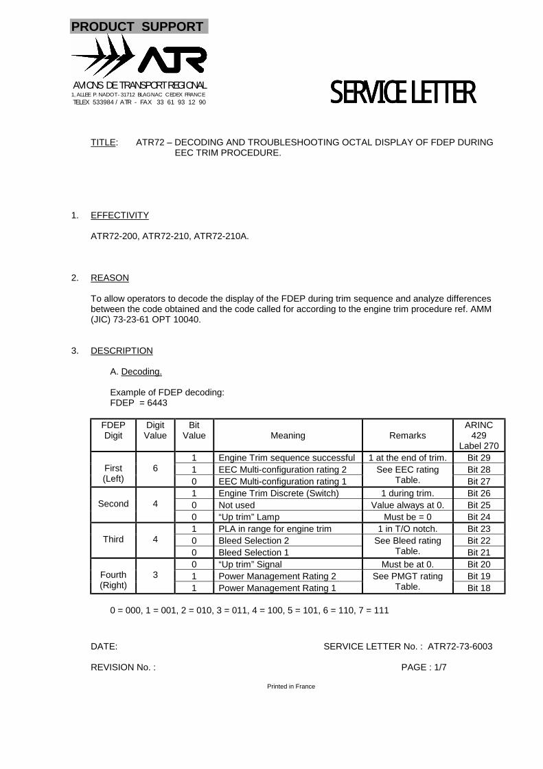
PRODUCT SUPPORT
AVIONS DE TRANSPORT REGIONAL1, ALLEE P. NADOT - 31712 BLAGNAC CEDEX FRANCE TELEX 533984 / ATR - FAX 33 61 93 12 90
DATE: SERVICE LETTER No. : ATR72-73-6003
REVISION No. : PAGE : 1/7
Printed in France
SERVICE LETTERSERVICE LETTERSERVICE LETTERSERVICE LETTERTITLE: ATR72 – DECODING AND TROUBLESHOOTING OCTAL DISPLAY OF FDEP DURING
EEC TRIM PROCEDURE.
1. EFFECTIVITY
ATR72-200, ATR72-210, ATR72-210A.
2. REASON
To allow operators to decode the display of the FDEP during trim sequence and analyze differencesbetween the code obtained and the code called for according to the engine trim procedure ref. AMM(JIC) 73-23-61 OPT 10040.
3. DESCRIPTION
A. Decoding.
Example of FDEP decoding:FDEP = 6443
FDEPDigit
DigitValue
BitValue Meaning Remarks
ARINC429
Label 2701 Engine Trim sequence successful 1 at the end of trim. Bit 291 EEC Multi-configuration rating 2 Bit 28First
(Left)6
0 EEC Multi-configuration rating 1See EEC rating
Table. Bit 271 Engine Trim Discrete (Switch) 1 during trim. Bit 260 Not used Value always at 0. Bit 25Second 40 “Up trim” Lamp Must be = 0 Bit 241 PLA in range for engine trim 1 in T/O notch. Bit 230 Bleed Selection 2 Bit 22Third 40 Bleed Selection 1
See Bleed ratingTable. Bit 21
0 “Up trim” Signal Must be at 0. Bit 201 Power Management Rating 2 Bit 19Fourth
(Right)3
1 Power Management Rating 1See PMGT rating
Table. Bit 18
0 = 000, 1 = 001, 2 = 010, 3 = 011, 4 = 100, 5 = 101, 6 = 110, 7 = 111
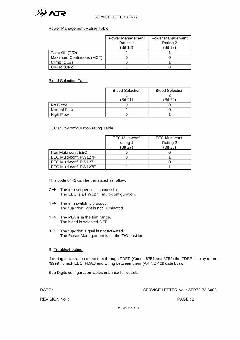
DATE : SERVICE LETTER No. : ATR72-73-6003
REVISION No. : PAGE : 2
Printed in France
SERVICE LETTER ATR72
Power Management Rating Table
Power ManagementRating 1(Bit 18)
Power ManagementRating 2(Bit 19)
Take Off (T/O) 1 1Maximum Continuous (MCT) 0 0Climb (CLB) 0 1Cruise (CRZ) 1 0
Bleed Selection Table
Bleed Selection1
(Bit 21)
Bleed Selection2
(Bit 22)No Bleed 0 0Normal Flow 1 0High Flow 0 1
EEC Multi-configuration rating Table
EEC Multi-conf.rating 1(Bit 27)
EEC Multi-conf.Rating 2(Bit 28)
Non Multi-conf. EEC 0 0EEC Multi-conf. PW127F 0 1EEC Multi-conf. PW127 1 0EEC Multi-conf. PW127E 1 1
This code 6443 can be translated as follow:
7 ! The trim sequence is successful.The EEC is a PW127F multi-configuration.
4 ! The trim switch is pressed.The “up-trim” light is not illuminated.
4 ! The PLA is in the trim range.The bleed is selected OFF.
3 ! The “up-trim” signal is not activated.The Power Management is on the T/O position.
B. Troubleshooting.
If during initialization of the trim through FDEP (Codes 8751 and 8752) the FDEP display returns“9999”, check EEC, FDAU and wiring between them (ARINC 429 data bus).
See Digits configuration tables in annex for details.
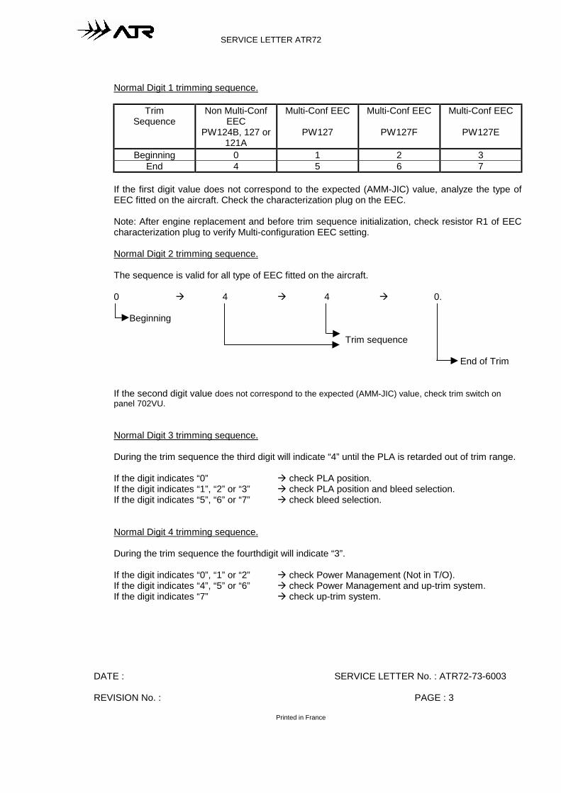
DATE : SERVICE LETTER No. : ATR72-73-6003
REVISION No. : PAGE : 3
Printed in France
SERVICE LETTER ATR72
Normal Digit 1 trimming sequence.
TrimSequence
Non Multi-ConfEEC
PW124B, 127 or121A
Multi-Conf EEC
PW127
Multi-Conf EEC
PW127F
Multi-Conf EEC
PW127E
Beginning 0 1 2 3End 4 5 6 7
If the first digit value does not correspond to the expected (AMM-JIC) value, analyze the type ofEEC fitted on the aircraft. Check the characterization plug on the EEC.
Note: After engine replacement and before trim sequence initialization, check resistor R1 of EECcharacterization plug to verify Multi-configuration EEC setting.
Normal Digit 2 trimming sequence.
The sequence is valid for all type of EEC fitted on the aircraft.
0 ! 4 ! 4 ! 0.
Beginning
Trim sequence
End of Trim
If the second digit value does not correspond to the expected (AMM-JIC) value, check trim switch onpanel 702VU.
Normal Digit 3 trimming sequence.
During the trim sequence the third digit will indicate “4” until the PLA is retarded out of trim range.
If the digit indicates “0” ! check PLA position.If the digit indicates “1”, “2” or “3” ! check PLA position and bleed selection.If the digit indicates “5”, “6” or “7” ! check bleed selection.
Normal Digit 4 trimming sequence.
During the trim sequence the fourthdigit will indicate “3”.
If the digit indicates “0”, “1” or “2” ! check Power Management (Not in T/O).If the digit indicates “4”, “5” or “6” ! check Power Management and up-trim system.If the digit indicates “7” ! check up-trim system.
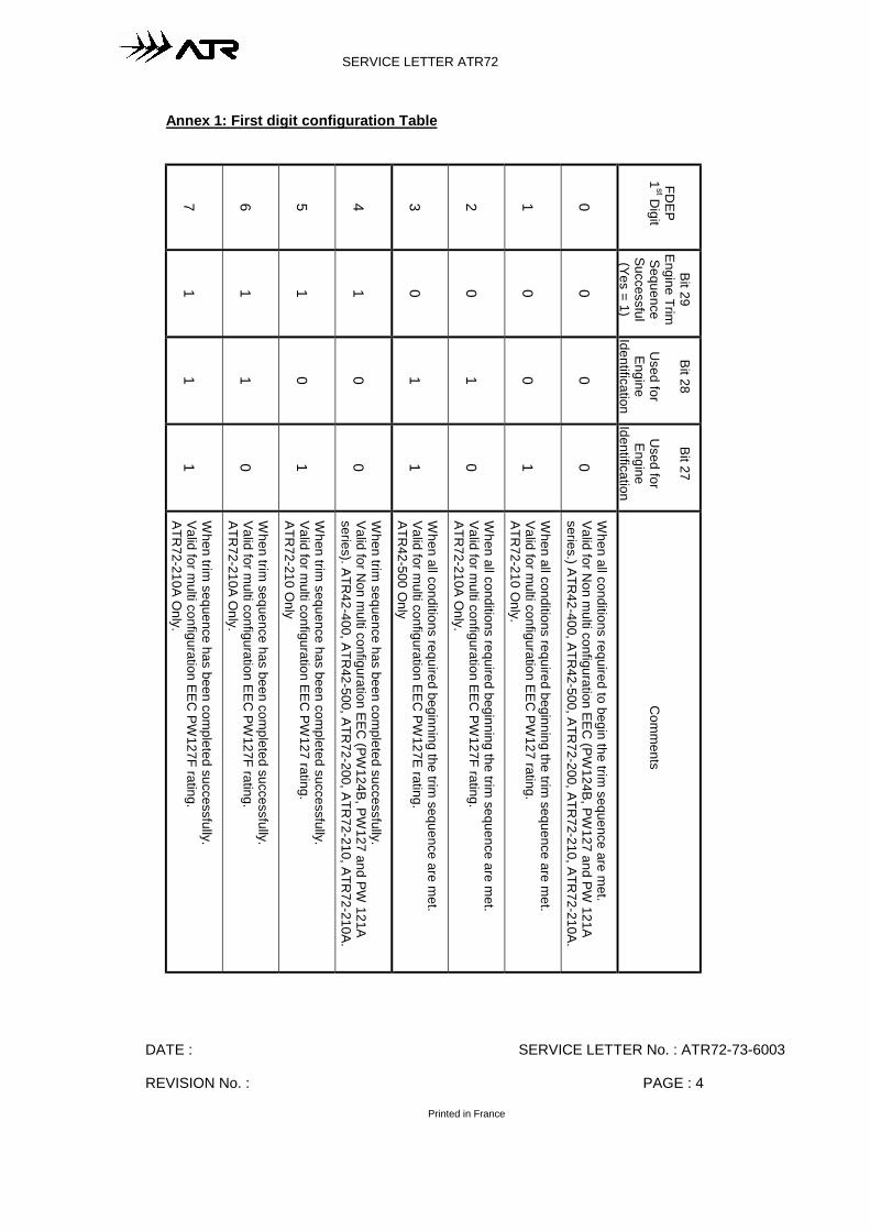
DATE : SERVICE LETTER No. : ATR72-73-6003
REVISION No. : PAGE : 4
Printed in France
SERVICE LETTER ATR72
Annex 1: First digit configuration Table
7 6 5 4 3 2 1 0
FDEP
1st D
igit
1 1 1 1 0 0 0 0
Bit 29Engine TrimSequenceSuccessful(Yes = 1)
1 1 0 0 1 1 0 0
Bit 28
Used for
EngineIdentification
1 0 1 0 1 0 1 0
Bit 27
Used for
EngineIdentification
When trim
sequence has been completed successfully.
Valid for multi configuration EEC
PW127F rating.
ATR72-210A O
nly.
When trim
sequence has been completed successfully.
Valid for multi configuration EEC
PW127F rating.
ATR72-210A O
nly.
When trim
sequence has been completed successfully.
Valid for multi configuration EEC
PW127 rating.
ATR72-210 O
nly
When trim
sequence has been completed successfully.
Valid for Non m
ulti configuration EEC (PW
124B, PW127 and PW
121Aseries). ATR
42-400, ATR42-500, ATR
72-200, ATR72-210, ATR
72-210A.
When all conditions required beginning the trim
sequence are met.
Valid for multi configuration EEC
PW127E rating.
ATR42-500 O
nly
When all conditions required beginning the trim
sequence are met.
Valid for multi configuration EEC
PW127F rating.
ATR72-210A O
nly.
When all conditions required beginning the trim
sequence are met.
Valid for multi configuration EEC
PW127 rating.
ATR72-210 O
nly.
When all conditions required to begin the trim
sequence are met.
Valid for Non m
ulti configuration EEC (PW
124B, PW127 and PW
121Aseries.) ATR
42-400, ATR42-500, ATR
72-200, ATR72-210, ATR
72-210A.
Com
ments
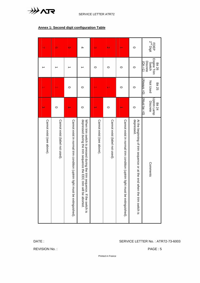
DATE : SERVICE LETTER No. : ATR72-73-6003
REVISION No. : PAGE : 5
Printed in France
SERVICE LETTER ATR72
Annex 1: Second digit configuration Table
7 6 5 4 3 2 1 0
FDEP
2nd D
igit
1 1 1 1 0 0 0 0
Bit 26Engine Trim
Switch
Discrete
(On =1)
1 1 0 0 1 1 0 0
Bit 25
Not U
sed
(Always =0)
1 0 1 0 1 0 1 0
Bit 24U
ptrim Lam
pD
iscrete
(Must be =0)
Cannot exist (see above).
Cannot exist (label not used).
Cannot exist in norm
al trim condition (uptrim
light must be extinguished).
When trim
switch is pressed during the trim
sequence. If the switch is
depressed during the trim sequence the EEC
trim w
ill be aborted.
Cannot exist (see above).
Cannot exist (label not used).
Cannot exist in norm
al trim condition (uptrim
light must be extinguished).
At the beginning of trim sequence or at the end w
hen the trim sw
itch isdepressed.
Com
ments
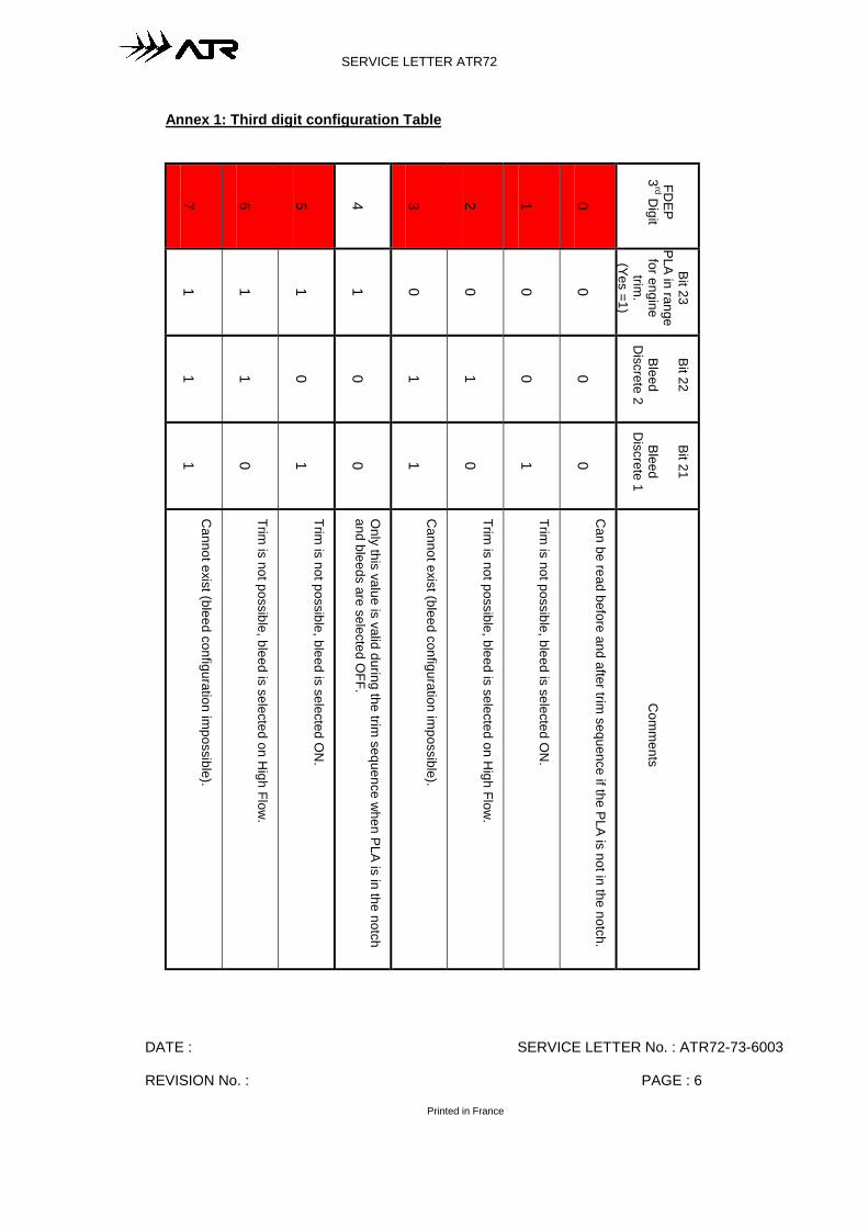
DATE : SERVICE LETTER No. : ATR72-73-6003
REVISION No. : PAGE : 6
Printed in France
SERVICE LETTER ATR72
Annex 1: Third digit configuration Table
7 6 5 4 3 2 1 0
FDEP
3rd D
igit
1 1 1 1 0 0 0 0
Bit 23PLA in range
for enginetrim
.(Yes =1)
1 1 0 0 1 1 0 0
Bit 22
BleedD
iscrete 2
1 0 1 0 1 0 1 0
Bit 21
BleedD
iscrete 1
Cannot exist (bleed configuration im
possible).
Trim is not possible, bleed is selected on H
igh Flow.
Trim is not possible, bleed is selected O
N.
Only this value is valid during the trim
sequence when PLA is in the notch
and bleeds are selected OFF.
Cannot exist (bleed configuration im
possible).
Trim is not possible, bleed is selected on H
igh Flow.
Trim is not possible, bleed is selected O
N.
Can be read before and after trim
sequence if the PLA is not in the notch.
Com
ments
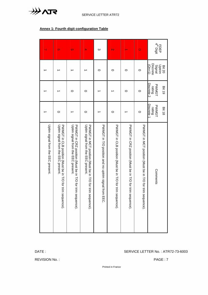
DATE : SERVICE LETTER No. : ATR72-73-6003
REVISION No. : PAGE : 7
Printed in France
SERVICE LETTER ATR72
Annex 1: Fourth digit configuration Table
7 6 5 4 3 2 1 0
FDEP
4th D
igit
1 1 1 1 0 0 0 0
Bit 20U
ptrimSignal
Discrete
(On=1)
1 1 0 0 1 1 0 0
Bit 19
PWM
GT
ratingD
iscrete 2
1 0 1 0 1 0 1 0
Bit 18
PWM
GT
ratingD
iscrete 1
Uptim
signal from the EEC
present.
PWM
GT in C
LB position (Must be in T/O
for trim sequence).
Uptim
signal from the EEC
present.
PWM
GT in C
RZ position (M
ust be in T/O for trim
sequence).U
ptim signal from
the EEC present.
PWM
GT in M
CT position (M
ust be in T/O for trim
sequence).U
ptim signal from
the EEC present.
PWM
GT in T/O
position and no uptrim signal from
EEC.
PWM
GT in C
LB position (Must be in T/O
for trim sequence).
PWM
GT in C
RZ position (M
ust be in T/O for trim
sequence).
PWM
GT in M
CT position (M
ust be in T/O for trim
sequence).
Com
ments