Embed Size (px)
Citation preview

390F LHydraulic Excavator
Engine
Engine Model Cat® C18 ACERT™
Power – ISO 14396 (metric) 405 kW (551 PS)
Power – ISO 9249 (metric) 391 kW (532 PS)
Drive
Maximum Travel Speed 4.5 km/h
Maximum Drawbar Pull 590 kN
Operating Weights
Minimum – Reach Confi guration 86 275 kg
Maximum – Mass Confi guration 92 020 kg

2
The 390F L is built to keep your production numbers up and your owning and operating costs down.
Not only does the machine’s C18 ACERT engine meet EU Stage IV emission standards, but it does so while giving you all the power, fuel efficiency, and reliability you need to succeed.
Where the real power comes in is through the hydraulic system. You can literally move tons of material all day long with a great deal of speed and precision. In fact, the hydraulic system and engine work together to keep fuel consumption to an absolute minimum – all without impacting your productivity.
When you add in a quiet operator environment that keeps you comfortable and productive, service points that make your routine maintenance quick and easy, and multiple Cat work tools that help you take on a variety of jobs, you simply won’t find a better 90 ton machine.
ContentsReliable and Productive .....................................4
Fuel Effi cient ........................................................6
Easy to Operate ...................................................8
Durable Structures ...........................................10
Durable Linkages ..............................................11
Versatile ..............................................................12
Integrated Technologies ..................................14
Safe Work Environment ...................................16
Serviceable ........................................................17
Sustainable ........................................................18
Complete Customer Care .................................18
Specifi cations ....................................................19
Standard Equipment .........................................32
Optional Equipment...........................................33
Notes ...................................................................34

3

Hydraulic Horsepower, a Cat AdvantageHydraulic horsepower is the actual machine power available to
do work through implements and work tools. It’s much more than
just the engine power under the hood – it’s a core strength that
differentiates Cat machines from other brands. In fact, pump and
other system components work to put more power to the ground,
in a highly controlled, user-friendly way. This means you will
move more material in less time and keep more money in your
pocket at the end of the day.
Control Like No OtherThe new Cat Adaptive Control System (ACS) valve optimizes
performance by intelligently managing restrictions and fl ows to
control machine motion, which means your operators will have
the power and precision they need and expect. It opens slowly
when your range of joystick lever movement is small and opens
rapidly when movement is high. It smartly puts fl ow exactly
where you need it when you need it, which leads to smoother
operation, greater effi ciency, and lower fuel consumption.
4
Reliable and ProductivePower to move your material with speed and precision

SmartBoom™
Reduces Stress and Vibrations Transmitted to the Machine
Rock Scraping (1)Scraping rock and fi nishing work is easy and fast. SmartBoom simplifi es the task and allows the
operator to fully concentrate on the stick and bucket while the boom freely goes up and down without
using pump fl ow.
Hammer Work (2)It has never been this productive and operator-friendly. The front parts automatically follow the hammer
while penetrating the rock. Blank shots or excessive force on the hammer are avoided, resulting in
longer life for the hammer and machine. Similar advantages are applicable when using vibratory plates.
Truck Loading (3)Loading trucks from a bench is more productive and fuel effi cient as the return cycle is reduced while
the boom down function does not require pump fl ow.
5
1 2 3
Auxiliary Hydraulics for Added VersatilityAuxiliary hydraulics give you greater tool versatility so you can
take on more work with just one machine, and there are several
options from which you can choose. A quick coupler circuit,
for example, will allow you to switch from one tool to another
in a matter of minutes.

6
Fuel EfficientEngineered to lower your operating costs

Proven TechnologyThe right technologies fi ne-tuned for the right applications result in:
• Improved Fluid Effi ciency – Up to 5% improvement over Stage IIIB products
(including Diesel Exhaust Fluid consumption).
• High Performance across a variety of applications.
• Enhanced Reliability through commonality and simplicity of design.
• Maximized Uptime and Reduced Cost with world-class Cat dealer support.
• Minimized Impact of Emission Systems with no operator interaction required.
• Durability with long service life.
• Better Fuel Economy with minimized maintenance costs.
• Same great power and response.
The Cat C18 ACERT engine meets EU Stage IV emission standards and it does so without
interrupting your job process. Simply turn the engine on and go to work. It will look for opportunities
in your work cycle to regenerate itself, and it will give you plenty of power for the task at hand –
all to help keep your owning and operating costs to an absolute minimum.
Fuel Savers That Add UpThe 390F L features two power modes to help manage fuel consumption: standard power
and economy. Two additional fuel-saving features are on-demand engine power and engine
idle shutdown. On-demand engine power keeps speed low during light loading and idling;
it automatically adjusts speed up when it senses a heavier load. Engine idle shutdown
automatically shuts the engine off when idling for more than a specifi ed amount of time
that you set, which can save signifi cant amounts of fuel and reduce emissions.
Biodiesel Not a ProblemThe C18 ACERT engine can run on biodiesel fuel up to B20 blended with ULSD. Just fi ll it up and go.
A Smart Design for Any TemperatureThe 390F L features a new side-by-side cooling system that allows you to put the machine to
work in extremely hot and cold conditions. The system is completely separated from the engine
compartment to reduce noise and heat. Plus it features easy-to-clean cores and a new variable-
speed fan that reverses to blow out unwanted debris that may accumulate during your work day.
7

8
Easy to OperateComfort and convenience to keep you productive all day long

Safe and Quiet CabThe cab contributes to your comfort thanks to special viscous
mounts and special roof lining and sealing, that limit vibration
and unnecessary sound.
Operators will enjoy the quietness and comfort of the all-new
cab that’s insulated to reduce sound inside by 3 dB over the
previous model.
Excellent ErgonomicsWide seats with air suspension and heat/cooling options, include
a reclining back, upper and lower slide adjustments, and height
and tilt angle adjustments to meet your needs for maximum
comfort. The fully automatic climate control system keeps operators
comfortable and productive all day long in either hot or cold
weather. Storage spaces are located in the front, rear, and side
consoles of the cab. A drink holder accommodates a large mug,
and a shelf behind the seat stores large lunch or toolboxes.
Power supply sockets are available for charging your electronic
devices like an MP3 player, a cell phone, or even a tablet.
Controls Just for YouThe right and left joystick consoles can be adjusted to improve your
comfort and productivity during the course of a day. The right
joystick features a button that will reduce engine speed when
you are not working to help save fuel. Touch it once and speed
reduces; touch it again and speed increases for normal operation.
9
Easy to Navigate MonitorThe new LCD monitor is easy to see and navigate. Not only can it memorize
up to 10 different work tools, it’s also programmable in up to 42 languages
to meet today’s diverse workforce. The monitor clearly displays critical
information you need to operate effi ciently and effectively. Plus it projects
the image from the standard rearview camera to help you see what’s going
on around you so you can stay safely focused on the job at hand.

10
Durable StructuresDesigned to work in your tough, heavy-duty applications
Stable UndercarriageLong variable gauge undercarriage
contributes signifi cantly to its outstanding
stability and durability, and it adjusts to
reduce shipping width.
Track shoes, links, rollers, idlers, and
fi nal drives are all built with high-tensile-
strength steel for long-term durability.
Cat GLT4 track link protects moving parts
by keeping water, debris, and dust out and
grease sealed in, which delivers longer
wear life and reduced noise when traveling.
Robust FramesThe 390F L is a robust, well-built machine
designed to give you a very long service
life. The upper frame includes special
mountings made specifi cally to support
the heavy-duty cab. It’s also reinforced
around areas that take on a lot of stress
like the boom foot, skirt, and counterweight
removal system.
Positive Pin Retention 2 (PPR2) prevents
looseness of the track pin in the track
link, reduces stress concentrations, and
eliminates pin walking for increased
service life.
Optional three-piece guide guards help
maintain track alignment to improve your
machine’s overall performance – whether
you’re traveling on a fl at, heavy bed of
rock or a steep, wet fi eld of mud.
Great WeightThe pressed 12 400 kg fi xed or removable
counterweights are built with thick steel
plates and reinforced fabrications to
make them less susceptible to damage,
and both have curved surfaces that
match the machine’s sleek, smooth
appearance along with integrated
housings to help protect the standard
rearview camera.

11
Built to LastThe 390F L is offered with a range of reach (R) and mass (ME)
booms and sticks. Each is built with internal baffl e plates and is
stress relieved for added durability, and each undergoes ultrasound
inspection to ensure quality and reliability. Large box-section
structures with thick, multi-plate fabrications, castings, and
forgings are used in high-stress areas such as the boom nose,
boom foot, boom cylinder, and stick foot to improve durability.
Also, the boom nose pin retention method is a captured fl ag
design for enhanced durability.
Booms, Sticks and Bucket Linkage for Any JobAn extra-long 10.0 m Reach boom (with 5.5 m or 4.4 m sticks) or
an 8.4 m General Purpose boom (with 5.5 m, 4.4 m or 3.4 m sticks)
offer you excellent all-around versatility for general excavation
work like multipurpose digging and loading. A 7.25 m Mass boom
(with 3.4 m or 2.92 m sticks) offer you enhanced performance in
heavy-duty material like rock. They provide higher digging forces
due to special boom and stick geometry, and bucket linkage and
cylinders are built for greater durability.
Sticks are matched to the boom. Longer sticks are better when
you need to dig deep or load trucks.
Bucket linkages with or without a lifting eye are available.
PinsAll front linkage pins have thick chrome plating, giving them
high wear resistance. Each pin diameter is made to distribute
the shear and bending loads associated with the stick and to
help ensure long pin, boom and stick life.
Talk to your Cat dealer to pick the best front linkage options
for your applications.
Durable LinkagesOptions to take on your far-reaching or up-close tasks

12
VersatileDo more jobs with one machine

1 2
3 4
Get the Most from One MachineThe Cat combination of machine and tool provides a
total solution for just about any application. Work tools
can be mounted either directly to the machine or to a quick
coupler, making it fast and easy to release one work tool
and pick up another.
Change Jobs QuicklyCat quick coupler brings the ability to quickly change
attachments and switch from job to job. The CW dedicated
coupler is the secure way to decrease downtime and
increase job site fl exibility and overall productivity.
Available tool control remembers pressures and fl ows for
up to 10 tools. Simply toggle through the monitor, select the
tool, and go to work for maximum effi ciency.
Dig, Rip and LoadA wide range of buckets dig everything from basic top
soil to extreme, harsh material like ore and high quartzite
granite. Rip through rock as an alternative to blasting in
quarries. High-capacity buckets load trucks in a minimum
number of passes for maximum productivity.
Break, Demolish and ScrapA hydraulic hammer ably equips your machine for breaking
rock in quarries. It will also make taking down bridge pillars
and heavily reinforced concrete on road demolition jobs
no problem.
Multi-processor and pulverizer attachments make your
390F L ideal for demolition jobs and processing the resulting
debris. Shears with 360° rotation mount to the machine
for processing scrap steel and metal.
Set Up Your Machine for ProfitabilityYour Cat dealer can install hydraulic kits to properly operate
all Cat Work Tool attachments, maximizing the machine’s
uptime and your profi t. All Cat Work Tool attachments
are supported by the same Cat dealer network as your
Cat machine.
1) General Duty (GD) 2) Heavy Duty (HD)3) Severe Duty (SD) 4) Extreme Duty (XD)
13
14
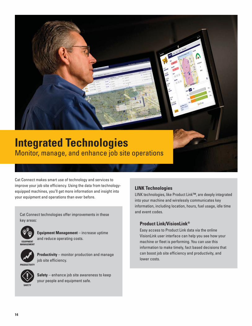
Integrated TechnologiesMonitor, manage, and enhance job site operations
Cat Connect makes smart use of technology and services to
improve your job site effi ciency. Using the data from technology-
equipped machines, you’ll get more information and insight into
your equipment and operations than ever before.
Cat Connect technologies offer improvements in these
key areas:
Equipment Management – increase uptime
and reduce operating costs.
Productivity – monitor production and manage
job site effi ciency.
Safety – enhance job site awareness to keep
your people and equipment safe.
LINK TechnologiesLINK technologies, like Product Link™, are deeply integrated
into your machine and wirelessly communicates key
information, including location, hours, fuel usage, idle time
and event codes.
Product Link/VisionLink®
Easy access to Product Link data via the online
VisionLink user interface can help you see how your
machine or fl eet is performing. You can use this
information to make timely, fact based decisions that
can boost job site effi ciency and productivity, and
lower costs.

15
GRADE TechnologiesGrade technologies combine digital design data and in-cab
guidance to help you reach target grade quickly and
accurately, with minimal staking and checking. That means
you’ll be more productive, complete jobs faster, in fewer
passes, using less fuel, at a lower cost.
Cat Grade Control Depth and SlopeThe integrated Cat Grade Control system delivers 2D bucket
tip elevation guidance to the cab to help operators create
precise planes and slopes. Real-time bucket tip elevation
guidance on the standard cab monitor indicates how much to
cut or fi ll. Fast response sensors deliver immediate feedback,
while optional integrated joystick buttons help operators make
quick adjustments to maintain grade. Built-in alerts can be set
to warn the operator if the linkage or bucket approaches a
predefi ned elevation or depth, such as when working in areas
with low ceilings, or digging near water lines. Staking and
checking is minimized, which reduces ground crews
and enhances job site safety.
Works best in simple 2D applications, such as digging trenches
and basements or grading steep embankments.
Cat AccuGrade™The dealer-installed AccuGrade system uses a dedicated
monitor with a digital design plan for 3D bucket tip positioning
and elevation guidance. AccuGrade indicates precisely where
to work and how much to cut or fi ll – eliminating staking
and checking.
Plug and play capability on the 390F L simplifi es upgrading.
Choose from satellite (GNSS) or total station (UTS) control
for large projects with complex designs.

Great ViewsAmple glass, coupled with the standard parallel wiper system, gives you
excellent visibility out front and to the side.
Halogen lights provide plenty of illumination. Cab and boom lights can be
programmed to stay on for up to 90 seconds after the engine has been turned
off to help you safely exit the machine. Optional High Intensity Discharge (HID)
lights are available for enhanced night-time visibility.
The standard rear vision camera greatly enhances visibility behind the
machine to help the operator work more productively. A panoramic rearview
is automatically displayed on the new multi-function monitor during reverse
travel. As an option, a second display can be added, providing a dedicated
full-time rearview of the job site.
Secure Contact PointsMultiple large steps as well as hand and guard
rails will get you into the cab as well as a leg up
to the catwalks and compartments. Extended hand
and guard rails allow you to safely climb to the
upper deck. Anti-skid plates on the catwalks,
the surface of the upper structure, and the top
of the storage box area reduce your slipping
hazards in all types of weather conditions.
They can be removed for cleaning.
Safe Work EnvironmentFeatures to help protect you day in and day out
16

17
Convenient Access Built InYou can reach routine maintenance items
like greasing points and a concentrated
remote greasing block on boom foot from
ground level.
Compartments feature wide service doors
designed to help prevent debris entry, and
they also securely latch in place to help
make your service work simpler.
Machine’s slip-resistant 500 mm wide
catwalks stretch the length of the 390F L
to provide safe access to major and
grouped service points, such as fuel
and oil fi lters, and fl uid taps.
Quick and Convenient Fluids ServiceOil sample and pressure ports provide
easy checking of machine condition
and are standard on every machine.
You can ensure fast, easy, and secure
changing of engine and hydraulic oil
with the QuickEvac™ option.
The fuel tank’s drain cock makes it easy
and simple for you to remove water and
sediment during routine maintenance.
Plus an integrated fuel level indicator
pops up to help you reduce the possibility
of fuel tank overfi lling.
An optional fast fi ll port accessible from
ground level can make refueling even
easier and faster.
A Smart Cooling DesignThe 390F L features a new side-by-
side cooling system with easy-to-clean
cores and a new variable-speed fan that
reverses to blow out unwanted debris that
may accumulate during your work day.
A Fresh IdeaSelecting ventilation inside the cab allows
outside to air enter through the fresh air
fi lter. The fi lter is conveniently located
on the side of the cab to make it easy to
reach and replace, and it is protected by
a lockable door that can be opened with
the engine key.
ServiceableDesigned to make your maintenance quick and easy
18
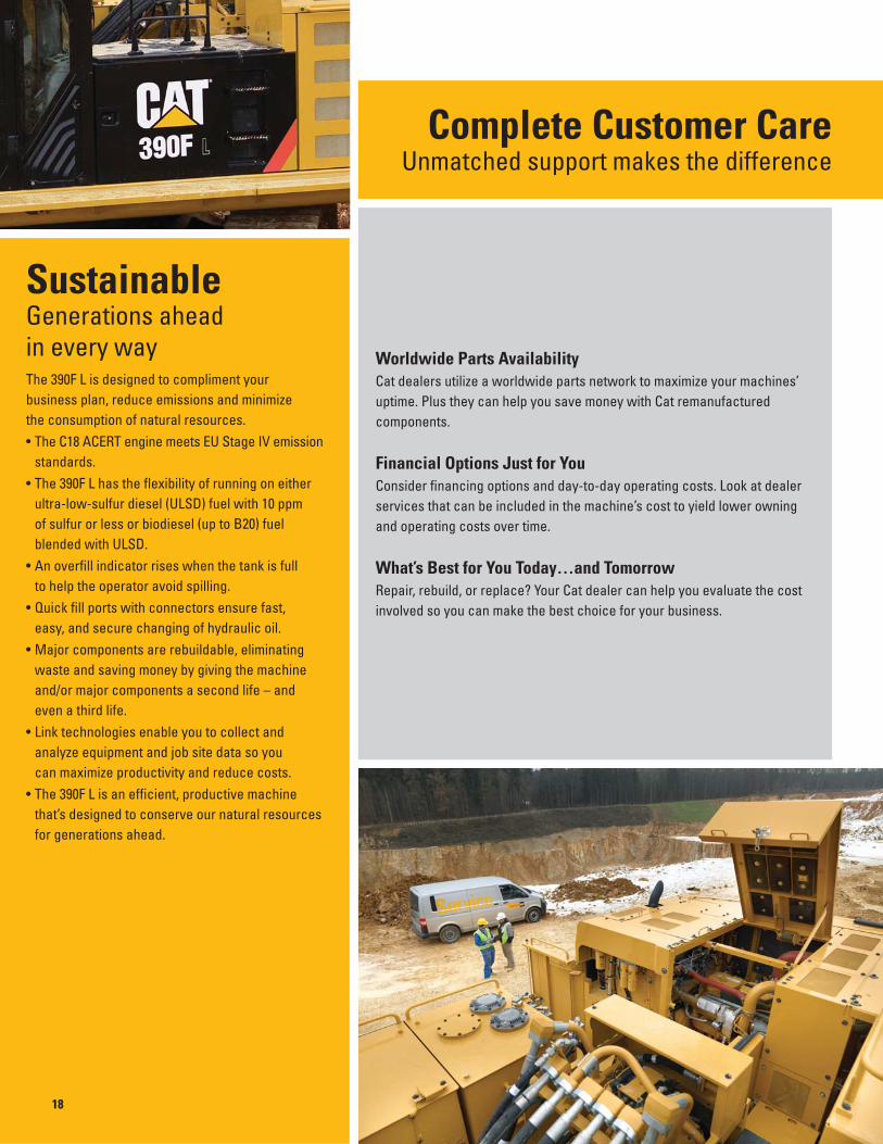
Worldwide Parts AvailabilityCat dealers utilize a worldwide parts network to maximize your machines’
uptime. Plus they can help you save money with Cat remanufactured
components.
Financial Options Just for YouConsider fi nancing options and day-to-day operating costs. Look at dealer
services that can be included in the machine’s cost to yield lower owning
and operating costs over time.
What’s Best for You Today…and TomorrowRepair, rebuild, or replace? Your Cat dealer can help you evaluate the cost
involved so you can make the best choice for your business.
SustainableGenerations ahead in every wayThe 390F L is designed to compliment your
business plan, reduce emissions and minimize
the consumption of natural resources.
• The C18 ACERT engine meets EU Stage IV emission
standards.
• The 390F L has the fl exibility of running on either
ultra-low-sulfur diesel (ULSD) fuel with 10 ppm
of sulfur or less or biodiesel (up to B20) fuel
blended with ULSD.
• An overfi ll indicator rises when the tank is full
to help the operator avoid spilling.
• Quick fi ll ports with connectors ensure fast,
easy, and secure changing of hydraulic oil.
• Major components are rebuildable, eliminating
waste and saving money by giving the machine
and/or major components a second life – and
even a third life.
• Link technologies enable you to collect and
analyze equipment and job site data so you
can maximize productivity and reduce costs.
• The 390F L is an effi cient, productive machine
that’s designed to conserve our natural resources
for generations ahead.
Complete Customer CareUnmatched support makes the difference

Engine
Engine Model Cat C18 ACERT
Power – ISO 14396 (metric) 405 kW (551 PS)
Power – ISO 9249 (metric) 391 kW (532 PS)
Bore 145 mm
Stroke 183 mm
Displacement 18.1 L
• The 390F L meets EU Stage IV emission standards.• No engine power derating required below 2300 m altitude.• Rating at 1,700 rpm (Implement).
Operating Weights
Gradeability 30°/70%
Minimum – Reach Confi guration 86 275 kg
Maximum – Mass Confi guration 92 020 kg
Drive
Maximum Travel Speed 4.5 km/h
Maximum Drawbar Pull 590 kN
Track
Track Options 900 mm/750 mm/650 mm
Number of Shoes Each Side 51
Number of Track Rollers Each Side 9
Number of Carrier Rollers Each Side 3
Swing Mechanism
Swing Speed 6.2 rpm
Swing Torque 260 kN∙m
Service Refill Capacities
Fuel Tank Capacity 1240 L
Cooling System 74 L
Engine Oil 60 L
Swing Drive (each) 19 L
Final Drive (each) 21 L
Hydraulic System Oil Capacity (including tank)
997 L
Hydraulic Tank Oil 813 L
DEF Tank 48 L
Hydraulic System
Main System – Maximum Flow (total)
Implement 952 L/min
Travel 1064 L/min
Swing System – Maximum Flow No swing pump
Maximum Pressure
Equipment – Normal 35 000 kPa
Travel 35 000 kPa
Swing 26 000 kPa
Pilot System
Maximum Flow 67 L/min
Maximum Pressure 4.0-4.4 MPa
Boom Cylinder
Bore 210 mm
Stroke 1967 mm
Stick Cylinder
Bore 220 mm
Stroke 2262 mm
HB2 – Family Bucket Cylinder
Bore 200 mm
Stroke 1451 mm
JC – Family Bucket Cylinder
Bore 220 mm
Stroke 1586 mm
Sound Performance
Operator Sound Pressure Level ISO 6396 74 dB(A)
Exterior Sound Power Level ISO 6395 109 dB(A)*
* Per European Union Directive 2000/14/EC as amended by 2005/88/EC.
• When properly installed and maintained, the cab offered by Caterpillar, when tested with doors and windows closed according to ANSI/SAE J1166 OCT98, meets OSHA and MSHA requirements for operator sound exposure limits in effect at time of manufacture.
• Hearing protection may be needed when operating with an open operator station and cab (when not properly maintained or doors/windows open) for extended periods or in a noisy environment.
Standards
Brakes SAE J1026/APR90
Cab/FOGS SAE J1356/FEB88 ISO 10262
DEF ISO 22241
390F L Hydraulic Excavator Specifications
19

20
390F L Hydraulic Excavator Specifications
DimensionsAll dimensions are approximate.
8
1
7
612
10
9
2
43
5
11
13 13
Boom Options Reach Boom GP Boom Mass Boom10.0 m 8.4 m 7.25 m
Stick Options R5.5 m R4.4 m R5.5 m R4.4 m G3.4 m M3.4 m M2.92 m
1 Height – with boom/stick installed mm 5490 5070 5840 5290 5160 5310 4890
2 Guardrail Height mm 3830 3830 3830 3830 3830 3830 3830
3 Counterweight Clearance mm 1640 1640 1640 1640 1640 1640 1640
4 Ground Clearance mm 900 900 900 900 900 900 900
5 Length – with boom/stick installed mm 16 290 16 330 14 500 14 690 14 720 13 550 13 690
6 Track Length mm 6358 6358 6358 6358 6358 6358 6358
7 Length to Center of Rollers mm 5120 5120 5120 5120 5120 5120 5120
8 Tail Swing Radius mm 4700 4700 4700 4700 4700 4700 4700
9 Track Gauge – retracted mm 2750 2750 2750 2750 2750 2750 2750
Track Gauge – extended mm 3510 3510 3510 3510 3510 3510 3510
10 Undercarriage Width – without steps
650 mm Shoes mm 4160 4160 4160 4160 4160 4160 4160
750 mm Shoes mm 4260 4260 4260 4260 4260 4260 4260
900 mm Shoes mm 4410 4410 4410 4410 4410 4410 4410
Undercarriage Width – including steps
650 mm Shoes mm 4450 4450 4450 4450 4450 4450 4450
750 mm Shoes mm 4450 4450 4450 4450 4450 4450 4450
900 mm Shoes mm 4450 4450 4450 4450 4450 4450 4450
11 Upperframe Width – without walkways mm 3470 3470 3470 3470 3470 3470 3470
12 Upperframe Width – with walkways mm 4510 4510 4510 4510 4510 4510 4510
13 Walkway Width (each) mm 520 520 520 520 520 520 520
Bucket Type GD GD GD GD SD SDV SDV
Bucket Capacity m3 3.9 3.9 4.6 4.6 4.6 6.0 6.0
Bucket Tip Radius mm 2424 2424 2319 2319 2319 2505 2505
Dimensions may vary depending on bucket selection.

390F L Hydraulic Excavator Specifications
21
Working RangesAll dimensions are approximate.
Boom Options 1
Reach Boom
2
GP Boom
3
Mass Boom10.0 m 8.4 m 7.25 m
Stick Options R5.5 m R4.4 m R5.5 m R4.4 m G3.4 m M3.4 m M2.92 m
1 Maximum Digging Depth mm 11 800 10 700 10 750 9650 8680 7640 7160
2 Maximum Reach at Ground Line mm 17 250 16 230 15 730 14 690 13 910 12 690 12 240
3 Maximum Loading Height mm 10 960 10 530 9730 9280 9100 8210 7990
4 Maximum Cutting Height mm 15 180 14 750 14 000 13 540 13 470 12 580 12 360
5 Minimum Loading Height mm 3320 4420 1950 3050 4030 3210 3680
6 Maximum Depth Cut for 2240 mm Level Bottom mm 11 700 10 590 10 650 9540 8550 7510 7020
7 Maximum Vertical Wall Digging Depth mm 8380 7380 7860 6850 6180 5090 4690
Bucket Digging Force (ISO) kN 364.8 363.3 364.8 363.3 470.9 470.9 470.4
Stick Digging Force (ISO) kN 235.9 276.0 235.9 276.0 325.5 325.5 356.3
Bucket Type GD GD GD GD SD SDV SDV
Bucket Capacity m3 3.9 3.9 4.6 4.6 4.6 6.0 6.0
Bucket Tip Radius mm 2424 2424 2319 2319 2319 2505 2505
Dimensions may vary depending on bucket selection.
1
2
3
4
5
6
7
8
9
10
11
12121315 10 911 8 7 6 5 4 3 2 1 0 -2 -3-1 Meters
0
1
2
3
4
5
6
7
8
9
4
5
6
7
8
9
10
11
12
Meters
13
14
15
16
1416171819
1
76
3
4
5
2
R5.5 m
R4.4 m
1
1
2
3
4
5
6
7
8
9
10
11
12121315 10 911 8 7 6 5 4 3 2 1 0 -2 -3-1 Meters
0
1
2
3
4
5
6
7
8
9
4
5
6
7
8
9
10
11
12
Meters
13
14
15
16
1416171819
1
7
6
3
4
5
2
R5.5 m
R4.4 m
G3.4 m
2
1
2
3
4
5
6
7
8
9
10
11
12121315 10 911 8 7 6 5 4 3 2 1 0 -2 -3-1 Meters
0
1
2
3
4
5
6
7
8
9
4
5
6
7
8
9
10
11
12
Meters
13
14
15
16
1416171819
1
7
6
3
4
5
2
M3.4 m
M2.92 m
3

22
390F L Hydraulic Excavator Specifications
Operating Weights and Ground Pressures
Boom Stick Bucket
900 mm Shoe 750 mm Shoe 650 mm Shoe
WeightGround
Pressure WeightGround
Pressure WeightGround
Pressure
R10.0 m R5.5 m 3.9 m3 89 827 kg 88.1 kPa 88 780 kg 104.5 kPa 87 906 kg 119.4 kPa
R10.0 m R4.4 m 3.9 m3 89 319 kg 87.6 kPa 88 272 kg 103.9 kPa 87 398 kg 118.7 kPa
GP8.4 m R5.5 m 4.6 m3 88 704 kg 87.0 kPa 87 657 kg 103.2 kPa 86 783 kg 117.8 kPa
GP8.4 m R4.4 m 4.6 m3 88 196 kg 86.5 kPa 87 149 kg 102.6 kPa 86 275 kg 117.2 kPa
GP8.4 m G3.4 m 4.6 m3 90 603 kg 88.9 kPa 89 556 kg 105.4 kPa 88 682 kg 120.4 kPa
M7.25 m M3.4 m 6.0 m3 92 022 kg 90.3 kPa 90 975 kg 107.1 kPa 90 101 kg 122.4 kPa
M7.25 m M2.92 m 6.0 m3 91 764 kg 90.0 kPa 90 717 kg 106.8 kPa 89 843 kg 122.0 kPa
Major Components Weights
Base Machine (with counterweight, without front linkage, without bucket)* kg
650 mm Tracks 66 739
750 mm Tracks 67 613
900 mm Tracks 68 660
Two Boom Cylinders 1804
Counterweight
Removal Type 12 400
Non-removal Type 12 400
Boom (includes lines, pins, stick cylinder)
Reach Boom – 10.0 m 9839
General Purpose Boom – 8.4 m 8392
Mass Boom – 7.25 m 8437
Stick (includes lines, pins, bucket cylinder, linkage)
R5.5 m 5430
R4.4 m 4922
G3.4 m 5186
M3.4 m 5447
M2.92 m 5189
Bucket
3.9 m3 GD 4094
4.6 m3 GD 4418
6.0 m3 SDV 7674
* Base machine includes 75 kg operator weight and 90% fuel weight, and undercarriage with center guard.

390F L Hydraulic Excavator Specifications
23
Reach Boom Lift Capacities – Counterweight: 12.4 mt – Without Bucket
1500 mm 3000 mm 4500 mm 6000 mm 7500 mm
mm
12 000 mm kg *9600 *9600 11 83010 500 mm kg *9300 *9300 12 880
9000 mm kg *9150 9050 13 6807500 mm kg *9150 8150 14 2806000 mm kg *19 800 *19 800 *9250 7500 14 6904500 mm kg *28 600 *28 600 *22 050 22 000 *9500 7050 14 9503000 mm kg *20 000 *20 000 *24 050 20 300 *9900 6800 15 0501500 mm kg *15 650 *15 650 *25 400 18 950 *10 450 6700 14 990
0 mm kg *16 950 *16 950 *25 950 18 150 10 650 6700 14 790–1500 mm kg *11 250 *11 250 *20 650 *20 650 *25 800 17 700 10 950 6900 14 420–3000 mm kg *12 200 *12 200 *16 750 *16 750 *26 100 24 700 *24 950 17 500 11 550 7300 13 880–4500 mm kg *17 800 *17 800 *22 900 *22 900 *28 300 24 950 *23 400 17 600 *11 800 7950 13 140–6000 mm kg *24 050 *24 050 *30 050 *30 050 *25 150 *25 150 *21 100 17 850 *11 500 9050 12 170–7500 mm kg *24 250 *24 250 *20 850 *20 850 *17 700 *17 700 *10 850 *10 850 10 910–9000 mm kg *14 850 *14 850 *12 650 *12 650 *9250 *9250 9230
9000 mm 10 500 mm 12 000 mm 13 500 mm 15 000 mm
mm
12 000 mm kg *9600 *9600 11 83010 500 mm kg *12 100 12 000 *9300 *9300 12 880
9000 mm kg *13 350 *13 350 *12 550 11 850 *10 050 9300 *9150 9050 13 6807500 mm kg *14 000 *14 000 *12 900 11 500 *12 100 9150 *9150 8150 14 2806000 mm kg *16 850 *16 850 *14 850 13 900 *13 400 11 100 *12 350 8900 *9250 7500 14 6904500 mm kg *18 250 16 750 *15 750 13 200 *14 000 10 600 *12 700 8600 *9500 7050 14 9503000 mm kg *19 550 15 650 *16 600 12 450 *14 550 10 100 12 800 8300 *10 250 6850 *9900 6800 15 0501500 mm kg *20 550 14 750 *17 300 11 850 14 950 9650 12 450 8000 *10 450 6700 14 990
0 mm kg *21 100 14 100 *17 700 11 350 14 600 9300 12 200 7750 10 650 6700 14 790–1500 mm kg *21 150 13 650 17 400 11 000 14 300 9050 12 050 7600 10 950 6900 14 420–3000 mm kg *20 650 13 450 17 200 10 800 14 200 8950 12 000 7550 11 550 7300 13 880–4500 mm kg *19 550 13 450 *16 450 10 800 *13 850 8950 *11 800 7950 13 140–6000 mm kg *17 700 13 650 *14 800 10 950 *11 900 9200 *11 500 9050 12 170–7500 mm kg *14 800 14 050 *11 800 11 400 *10 850 *10 850 10 910–9000 mm kg *9800 *9800 *9250 *9250 9230
* Indicates that the load is limited by hydraulic lifting capacity rather than tipping load. The above loads are in compliance with hydraulic excavator lift capacity standard ISO 10567:2007. They do not exceed 87% of hydraulic lifting capacity or 75% of tipping load. Weight of all lifting accessories must be deducted from the above lifting capacities. Lifting capacities are based on the machine standing on a firm, uniform supporting surface. The use of a work tool attachment point to handle/lift objects, could affect the machine lift performance.
Lift capacity stays with ±5% for all available track shoes.
Always refer to the appropriate Operation and Maintenance Manual for specific product information.
ISO 10567
R5.5 m
R5.5HB
10.0 m
3510 mm Extended
650 mm Double Grouser
6358 mm
5120 mm

24
390F L Hydraulic Excavator Specifications
Reach Boom Lift Capacities – Counterweight: 12.4 mt – Without Bucket
3000 mm 4500 mm 6000 mm 7500 mm
mm
12 000 mm kg *12 950 *12 950 10 51010 500 mm kg *12 450 12 200 11 680
9000 mm kg *12 250 10 500 12 5607500 mm kg *12 250 9400 13 2106000 mm kg *28 100 *28 100 *21 950 *21 950 *12 450 8600 13 6604500 mm kg *24 050 21 100 12 400 8100 13 9403000 mm kg *25 700 19 650 12 050 7800 14 0401500 mm kg *26 450 18 700 11 950 7700 13 980
0 mm kg *13 250 *13 250 *26 400 18 200 12 100 7750 13 760–1500 mm kg *20 150 *20 150 *25 600 18 000 12 550 8050 13 370–3000 mm kg *18 050 *18 050 *28 450 25 550 *24 200 18 050 *13 050 8600 12 780–4500 mm kg *26 900 *26 900 *25 800 *25 800 *22 100 18 250 *12 800 9500 11 970–6000 mm kg *24 450 *24 450 *22 000 *22 000 *19 100 18 700 *12 150 11 100 10 900–7500 mm kg *16 750 *16 750 *14 650 *14 650 *10 750 *10 750 9460
9000 mm 10 500 mm 12 000 mm 13 500 mm
mm
12 000 mm kg *13 000 *13 000 *12 950 *12 950 10 51010 500 mm kg *14 450 *14 450 *12 450 12 200 11 680
9000 mm kg *14 750 14 750 *13 800 11 500 *12 250 10 500 12 5607500 mm kg *17 150 *17 150 *15 300 14 250 *14 050 11 300 *12 250 9400 13 2106000 mm kg *18 400 17 350 *16 100 13 650 *14 500 10 900 13 300 8800 *12 450 8600 13 6604500 mm kg *19 700 16 300 *16 900 12 950 *14 950 10 500 13 050 8600 12 400 8100 13 9403000 mm kg *20 750 15 350 *17 600 12 350 *15 350 10 100 12 800 8350 12 050 7800 14 0401500 mm kg *21 450 14 650 *18 050 11 850 15 000 9750 12 600 8100 11 950 7700 13 980
0 mm kg *21 650 14 150 17 850 11 450 14 750 9450 12 400 7950 12 100 7750 13 760–1500 mm kg *21 300 13 900 17 650 11 200 14 550 9300 12 550 8050 13 370–3000 mm kg *20 350 13 850 *17 200 11 150 *14 500 9300 *13 050 8600 12 780–4500 mm kg *18 750 14 000 *15 750 11 250 *12 800 9500 11 970–6000 mm kg *16 150 14 300 *13 100 11 650 *12 150 11 100 10 900–7500 mm kg *11 850 *11 850 *10 750 *10 750 9460
* Indicates that the load is limited by hydraulic lifting capacity rather than tipping load. The above loads are in compliance with hydraulic excavator lift capacity standard ISO 10567:2007. They do not exceed 87% of hydraulic lifting capacity or 75% of tipping load. Weight of all lifting accessories must be deducted from the above lifting capacities. Lifting capacities are based on the machine standing on a firm, uniform supporting surface. The use of a work tool attachment point to handle/lift objects, could affect the machine lift performance.
Lift capacity stays with ±5% for all available track shoes.
Always refer to the appropriate Operation and Maintenance Manual for specific product information.
ISO 10567
R4.4 m
R4.4HB
10.0 m
3510 mm Extended
650 mm Double Grouser
6358 mm
5120 mm

390F L Hydraulic Excavator Specifications
25
GP Boom Lift Capacities – Counterweight: 12.4 mt – Without Bucket
1500 mm 3000 mm 4500 mm 6000 mm 7500 mm
mm
12 000 mm kg *8950 *8950 9840 10 500 mm kg *8350 *8350 11 080
9000 mm kg *8050 *8050 12 0107500 mm kg *7950 *7950 12 6806000 mm kg *7950 *7950 13 1504500 mm kg *26 650 *26 650 *21 800 *21 800 *8100 *8100 13 4403000 mm kg *31 000 *31 000 *24 350 22 750 *8450 *8450 13 5501500 mm kg *34 200 29 800 *26 450 21 500 *8900 8850 13 490
0 mm kg *18 900 *18 900 *35 800 28 500 *27 750 20 600 *9600 8950 13 260–1500 mm kg *14 150 *14 150 *23 150 *23 150 *35 900 27 800 *28 150 20 000 *10 550 9250 12 840–3000 mm kg *16 300 *16 300 *20 100 *20 100 *29 350 *29 350 *34 700 27 600 *27 550 19 750 *12 050 9950 12 230–4500 mm kg *22 150 *22 150 *27 000 *27 000 *37 700 *37 700 *32 150 27 700 *25 850 19 750 *14 300 11 050 11 390–6000 mm kg *35 500 *35 500 *35 100 *35 100 *28 000 *28 000 *22 650 20 000 *14 450 13 050 10 250–7500 mm kg *26 500 *26 500 *21 600 *21 600 *17 150 *17 150 *13 200 *13 200 8710
9000 mm 10 500 mm 12 000 mm 13 500 mm 15 000 mm
mm
12 000 mm kg *8950 *8950 9840 10 500 mm kg *10 850 *10 850 *8350 *8350 11 080
9000 mm kg *12 900 *12 900 *8050 *8050 *8050 *8050 12 0107500 mm kg *14 300 *14 300 *11 400 *11 400 *7950 *7950 12 6806000 mm kg *17 300 *17 300 *15 850 14 750 *13 400 11 650 *7950 *7950 13 1504500 mm kg *18 800 18 200 *16 800 14 200 *15 250 11 350 *8100 *8100 13 4403000 mm kg *20 400 17 300 *17 800 13 650 *15 950 11 000 *8850 *8850 *8450 *8450 13 5501500 mm kg *21 750 16 500 *18 650 13 100 15 950 10 650 *8900 8850 13 490
0 mm kg *22 700 15 850 19 150 12 700 15 650 10 400 *9600 8950 13 260–1500 mm kg *23 000 15 400 18 800 12 350 15 450 10 200 *10 550 9250 12 840–3000 mm kg *22 550 15 200 18 650 12 250 *15 350 10 200 *12 050 9950 12 230–4500 mm kg *21 150 15 200 *17 250 12 300 *14 300 11 050 11 390–6000 mm kg *18 250 15 450 *14 450 13 050 10 250–7500 mm kg *13 200 *13 200 8710
* Indicates that the load is limited by hydraulic lifting capacity rather than tipping load. The above loads are in compliance with hydraulic excavator lift capacity standard ISO 10567:2007. They do not exceed 87% of hydraulic lifting capacity or 75% of tipping load. Weight of all lifting accessories must be deducted from the above lifting capacities. Lifting capacities are based on the machine standing on a firm, uniform supporting surface. The use of a work tool attachment point to handle/lift objects, could affect the machine lift performance.
Lift capacity stays with ±5% for all available track shoes.
Always refer to the appropriate Operation and Maintenance Manual for specific product information.
ISO 10567
R5.5 m
R5.5HB
8.4 m
3510 mm Extended
650 mm Double Grouser
6358 mm
5120 mm

26
390F L Hydraulic Excavator Specifications
GP Boom Lift Capacities – Counterweight: 12.4 mt – Without Bucket
1500 mm 3000 mm 4500 mm 6000 mm
mm
10 500 mm kg *11 350 *11 350 9800 9000 mm kg *10 900 *10 900 10 8307500 mm kg *10 700 *10 700 11 5806000 mm kg *10 750 *10 750 12 0904500 mm kg *30 400 *30 400 *11 050 10 650 12 4003000 mm kg *34 100 30 700 *11 500 10 250 12 5201500 mm kg *36 200 29 150 *12 200 10 150 12 460
0 mm kg *36 500 28 400 *13 300 10 350 12 210–1500 mm kg *24 050 *24 050 *35 450 28 100 *14 850 10 850 11 760–3000 mm kg *23 500 *23 500 *33 450 *33 450 *33 200 28 150 *16 450 11 800 11 080–4500 mm kg *33 150 *33 150 *36 200 *36 200 *29 500 28 500 *16 050 13 500 10 140–6000 mm kg *28 650 *28 650 *23 900 *23 900 *14 950 *14 950 8840
7500 mm 9000 mm 10 500 mm 12 000 mm
mm
10 500 mm kg *15 400 *15 400 *11 350 *11 350 9800 9000 mm kg *17 300 *17 300 *13 350 *13 350 *10 900 *10 900 10 8307500 mm kg *18 000 *18 000 *16 850 14 800 *10 700 *10 700 11 5806000 mm kg *21 850 *21 850 *19 200 18 600 *17 450 14 450 *11 750 11 450 *10 750 *10 750 12 0904500 mm kg *24 200 23 500 *20 600 17 800 *18 200 14 000 *15 150 11 250 *11 050 10 650 12 4003000 mm kg *26 400 22 200 *21 900 17 050 *19 000 13 550 16 300 11 000 *11 500 10 250 12 5201500 mm kg *28 000 21 200 *22 950 16 400 *19 550 13 100 16 000 10 750 *12 200 10 150 12 460
0 mm kg *28 650 20 550 *23 450 15 900 19 250 12 800 15 850 10 600 *13 300 10 350 12 210–1500 mm kg *28 300 20 200 *23 200 15 600 19 050 12 600 *14 850 10 850 11 760–3000 mm kg *26 850 20 150 *22 050 15 550 *18 050 12 600 *16 450 11 800 11 080–4500 mm kg *24 150 20 350 *19 600 15 750 *16 050 13 500 10 140–6000 mm kg *19 400 *19 400 *14 950 *14 950 8840
* Indicates that the load is limited by hydraulic lifting capacity rather than tipping load. The above loads are in compliance with hydraulic excavator lift capacity standard ISO 10567:2007. They do not exceed 87% of hydraulic lifting capacity or 75% of tipping load. Weight of all lifting accessories must be deducted from the above lifting capacities. Lifting capacities are based on the machine standing on a firm, uniform supporting surface. The use of a work tool attachment point to handle/lift objects, could affect the machine lift performance.
Lift capacity stays with ±5% for all available track shoes.
Always refer to the appropriate Operation and Maintenance Manual for specific product information.
ISO 10567
R4.4 m
R4.4HB
8.4 m
3510 mm Extended
650 mm Double Grouser
6358 mm
5120 mm

390F L Hydraulic Excavator Specifications
27
GP Boom Lift Capacities – Counterweight: 12.4 mt – Without Bucket
4500 mm 6000 mm 7500 mm 9000 mm 10 500 mm
mm
10 500 mm kg *15 450 *15 450 8740 9000 mm kg *18 750 18 750 *14 500 *14 500 9890 7500 mm kg *21 450 *21 450 *19 250 18 350 *17 150 14 050 *14 100 13 550 10 7106000 mm kg *28 700 *28 700 *23 350 *23 350 *20 200 17 750 *18 250 13 800 *14 050 12 200 11 2604500 mm kg *32 800 31 050 *25 500 22 400 *21 400 17 050 *18 800 13 400 *14 250 11 400 11 5903000 mm kg *27 300 21 250 *22 450 16 350 *19 300 13 000 *14 800 10 950 11 7201500 mm kg *28 250 20 450 *23 100 15 800 19 150 12 650 *15 650 10 900 11 650
0 mm kg *33 250 27 850 *28 200 20 000 *23 100 15 450 18 900 12 450 16 850 11 150 11 380–1500 mm kg *21 450 *21 450 *33 300 27 900 *27 150 19 850 *22 300 15 350 *18 250 12 400 *17 050 11 850 10 900–3000 mm kg *35 400 *35 400 *30 150 28 150 *24 900 20 000 *20 350 15 450 *16 600 13 200 10 170–4500 mm kg *29 450 *29 450 *25 450 *25 450 *21 000 20 400 *16 050 15 900 *15 500 *15 500 9130 –6000 mm kg *18 000 *18 000 *13 500 *13 500 *13 000 *13 000 7610
* Indicates that the load is limited by hydraulic lifting capacity rather than tipping load. The above loads are in compliance with hydraulic excavator lift capacity standard ISO 10567:2007. They do not exceed 87% of hydraulic lifting capacity or 75% of tipping load. Weight of all lifting accessories must be deducted from the above lifting capacities. Lifting capacities are based on the machine standing on a firm, uniform supporting surface. The use of a work tool attachment point to handle/lift objects, could affect the machine lift performance.
Lift capacity stays with ±5% for all available track shoes.
Always refer to the appropriate Operation and Maintenance Manual for specific product information.
ISO 10567
G3.4 m
G3.4JC
8.4 m
3510 mm Extended
650 mm Double Grouser
6358 mm
5120 mm

28
390F L Hydraulic Excavator Specifications
Mass Boom Lift Capacities – Counterweight: 12.4 mt – Without Bucket
3000 mm 4500 mm 6000 mm 7500 mm 9000 mm
mm
10 500 mm kg *17 250 *17 250 6970 9000 mm kg *21 550 *21 550 *15 800 *15 800 8380 7500 mm kg *23 200 *23 200 *18 850 18 400 *15 200 *15 200 9330 6000 mm kg *29 000 *29 000 *24 600 24 400 *21 850 18 050 *15 100 *15 100 9960 4500 mm kg *45 150 *45 150 *32 650 *32 650 *26 450 23 350 *22 700 17 500 *15 450 13 950 10 3303000 mm kg *35 800 31 100 *28 100 22 250 *23 500 16 950 *16 200 13 350 10 4801500 mm kg *37 200 29 750 *29 050 21 400 *23 850 16 400 *17 450 13 300 10 400
0 mm kg *27 900 *27 900 *36 650 29 100 *28 900 20 900 *23 450 16 100 *19 400 13 700 10 100–1500 mm kg *23 500 *23 500 *41 650 *41 650 *34 200 28 900 *27 250 20 700 *21 650 16 000 *19 450 14 800 9550 –3000 mm kg *38 650 *38 650 *36 350 *36 350 *29 650 29 150 *23 550 20 850 *18 450 17 050 8700 –4500 mm kg *26 650 *26 650 *22 050 *22 050 *15 900 *15 900 7450
* Indicates that the load is limited by hydraulic lifting capacity rather than tipping load. The above loads are in compliance with hydraulic excavator lift capacity standard ISO 10567:2007. They do not exceed 87% of hydraulic lifting capacity or 75% of tipping load. Weight of all lifting accessories must be deducted from the above lifting capacities. Lifting capacities are based on the machine standing on a firm, uniform supporting surface. The use of a work tool attachment point to handle/lift objects, could affect the machine lift performance.
Lift capacity stays with ±5% for all available track shoes.
Always refer to the appropriate Operation and Maintenance Manual for specific product information.
ISO 10567
M3.4 m
M3.4JC
7.25 m
3510 mm Extended
650 mm Double Grouser
6358 mm
5120 mm

390F L Hydraulic Excavator Specifications
29
Mass Boom Lift Capacities – Counterweight: 12.4 mt – Without Bucket
3000 mm 4500 mm 6000 mm 7500 mm 9000 mm
mm
10 500 mm kg *21 000 *21 000 6290 9000 mm kg *22 700 *22 700 *19 000 *19 000 7820 7500 mm kg *24 400 *24 400 *18 200 *18 200 8830 6000 mm kg *39 800 *39 800 *30 550 *30 550 *25 650 24 200 *22 750 17 950 *18 150 16 350 9500 4500 mm kg *34 050 32 600 *27 350 23 150 *23 400 17 450 *18 550 15 000 9890 3000 mm kg *36 700 30 800 *28 800 22 200 *23 950 16 950 *19 550 14 350 10 0401500 mm kg *37 450 29 650 *29 400 21 450 *24 100 16 500 *21 150 14 250 9960
0 mm kg *26 100 *26 100 *36 200 29 200 *28 800 21 000 *23 250 16 250 *20 900 14 800 9640 –1500 mm kg *40 200 *40 200 *33 100 29 150 *26 600 20 900 *20 550 16 300 *20 250 16 150 9060 –3000 mm kg *33 150 *33 150 *27 850 *27 850 *21 950 21 250 *18 800 *18 800 8170 –4500 mm kg *18 750 *18 750 *15 650 *15 650 6740
* Indicates that the load is limited by hydraulic lifting capacity rather than tipping load. The above loads are in compliance with hydraulic excavator lift capacity standard ISO 10567:2007. They do not exceed 87% of hydraulic lifting capacity or 75% of tipping load. Weight of all lifting accessories must be deducted from the above lifting capacities. Lifting capacities are based on the machine standing on a firm, uniform supporting surface. The use of a work tool attachment point to handle/lift objects, could affect the machine lift performance.
Lift capacity stays with ±5% for all available track shoes.
Always refer to the appropriate Operation and Maintenance Manual for specific product information.
ISO 10567
M2.92 m
M2.92JC
7.25 m
3510 mm Extended
650 mm Double Grouser
6358 mm
5120 mm

30
390F L Hydraulic Excavator Specifications
Bucket Specifications and Compatibility
Linkage
Width Capacity Weight Fill Reach Boom GP Boom Mass Boom
mm m3 kg % R5.5 m R4.4 m R5.5 m R4.4 m G3.4 m M3.4 m M2.92 m
Without Quick Coupler
General Duty (GD) HB2 1100 2.2 2856 100% – – –
HB2 1350 2.9 3187 100% – – –
HB2 1650 3.7 3650 100% – – –
HB2 1900 4.3 3923 100% – – –
HB2 2000 4.6 4032 100% – – –
Heavy Duty (HD) JC 1750 4.1 4799 100% – – – –
Severe Duty (SD) JC 2300 5.4 6809 90% – – – –
JC 2400 5.7 7015 90% – – – –
JC 2500 6.0 7342 90% – – – –
Extreme Duty (XD) JC 2200 5.0 6557 90% – – – –
JC 2300 5.4 7733 90% – – – –
JC 2400 5.7 7968 90% – – – –
Maximum dynamic load pin on (payload + bucket) kg 6350 7535 8850 10 420 11 430 14 600 15 850
With Quick Coupler (CW-70)
Severe Duty (SD) JC 2300 5.4 6559 90% – – – –
JC 2400 5.7 6765 90% – – – –
Maximum dynamic load with CW coupler (payload + bucket) kg 4930 6115 7430 9000 10 010 13 180 14 430
The above figures are based on maximum recommended dynamic working weights with front linkage fully extended at ground line with bucket curled. They do not exceed a stability ratio of 1.25.
Maximum Material Density
2100 kg/m3 or greater
1800 kg/m3 or greater
1500 kg/m3 or less
1200 kg/m3 or less
Capacity based on ISO 7451. 900 kg/m3 or less
Bucket weights include HD Long tips. Not Recommended
Caterpillar recommends using appropriate work tools to maximize the value customers receive from our products. Use of work tools, including buckets, which are outside of Caterpillar’s recommendations or specifications for weight, dimensions, flows, pressures, etc. may result in less-than-optimal performance, including but not limited to reductions in production, stability, reliability, and component durability. Improper use of a work tool resulting in sweeping, prying, twisting and/or catching of heavy loads will reduce the life of the boom and stick.

390F L Hydraulic Excavator Specifications
31
Work Tool Offering Guide*
Boom Type Reach Boom – 10.0 m GP Boom – 8.4 m Mass Boom – 7.25 m
Stick Size R5.5 m R4.4 m R5.5 m R4.4 m R3.4 m M3.4 m M2.92 m
Multi-Processor MP40 MP40 MP40 MP40 MP40 MP40 MP40
Mobile Scrap and Demolition Shear S385C** S385C** S385C** S385C** S385C** S385C** S385C**
CW Quick Coupler CW70 CW70 CW70 CW70 CW70 CW70 CW70
Rippers These work tools are available for the 390F L. Consult your Cat dealer for proper match.
*Matches are dependent on excavator configurations. Consult your Cat dealer for proper work tool match.
**Pin on only.

32
390F L Standard Equipment
CAB
• Parallel wiper and washer• Mirrors• Pressurized operator station
with positive fi ltration• Laminated glass front upper window
and tempered other windows• Sliding upper door window
(left-hand cab door)• Removable lower windshield
with in cab storage bracket• Openable skylight• Interior:
– Glass-breaking safety hammer – Coat hook – Beverage holder – Literature holder – Interior lighting – AM/FM radio mounting (DIN size) – Two 12V stereo speakers – Storage shelf suitable for lunch or toolbox – Power supply with 12V, two power outlets (10 amp) – Thumb wheel modulation joystick for use with combined auxiliary control – Sun screen – Air conditioner, heater and defroster with climate control
• Seat: – Seatbelt, 76 mm – Adjustable armrest – Height adjustable joystick consoles – Neutral lever (lock out) for all controls – Travel control pedals with removable hand levers – Capability of installing two additional pedals – Two speed travel – Floor mat, washable
• Monitor: – Clock – Video ready – Color LCD display with warning, fi lter/fl uid change, and working hour information – Language display (full graphic and full color display) – Machine condition, error code and tool mode setting information – Start-up level check for engine oil, engine coolant and hydraulic oil – Warning, fi lter/fl uid change and working hour information – Fuel consumption meter
ELECTRICAL
• 80 amp alternator• Circuit breaker• Battery, standard
ENGINE
• C18 ACERT diesel engine• EU Stage IV emission standards• 2300 m altitude capability with no derate• Up to B20 Biodiesel capable• Automatic engine speed control• Electric priming pump with switch• Water separator in fuel line including
water level sensor and indicator• Economy and standard power modes• Air cleaner• Side-by-side cooling system• Steel wall between engine
and pump compartment• Primary fi lter with water separator
and water separator indicator switch• Starting kit, cold weather, –18° C• Primary fuel fi lter• Secondary fuel fi lter• Tertiary fuel fi lter• Quick drains, engine and hydraulic oil
(QuickEvac)
HYDRAULIC SYSTEM
• Reverse swing dampening valve• Automatic swing parking brake• High-performance hydraulic return fi lter• Regeneration circuit for boom and stick• Capability of installing additional
auxiliary circuits• Reversing cooling fan• Bio oil capable• SmartBoom
LIGHTS
• Cab and boom lights with time delay• Exterior lights integrated into storage box
UNDERCARRIAGE/UPPERFRAME
• Grease Lubricated Track with PPR2 GLT4, resin seal
• Heavy duty track roller and idler• Track motor guards• Towing eye on base frame• Heavy duty bottom guards on upperframe• Counterweight with lifting eyes
(fi xed or removable)
SAFETY AND SECURITY
• Cat one key security system• Door locks• Cap locks on fuel and hydraulic tanks• Lockable external tool/storage box• Signaling/warning horn• Secondary engine shutoff switch• Mirrors• Rear window for emergency exit• Rear vision camera• Capability to connect a beacon• Bolt on FOGS capability• Service walkways• Safety hammer for breaking cab glass
INTEGRATED TECHNOLOGIES
• Product Link• Rear vision camera
Standard Equipment
Standard equipment may vary. Consult your Cat dealer for details.

33
390F L Optional Equipment
FRONT LINKAGE
• Reach boom 10.0 m (with or without BLCV/SLCV): – R5.5HB2 (with or without CGC) – R4.4HB2 (with or without CGC) – HB2 – family bucket linkage (with or without lifting eye)
• General Purpose boom 8.4 m (with or without BLCV/SLCV): – R5.5HB2 (with or without CGC) – R4.4HB2 (with or without CGC) – G3.4JC – HB2 – family bucket linkage (with or without lifting eye) – JC – family bucket linkage (with or without lifting eye)
• Mass boom 7.25 m (with or without BLCV/SLCV): – M3.4JC – M2.92JC – JC – family bucket linkage (with or without lifting eye)
TRACK
• Double grouser, Heavy Duty, 650 mm• Double grouser, Heavy Duty, 750 mm• Double grouser, Heavy Duty, 900 mm
GUARDS
• FOGS (Falling Object Guard System) including overhead and windshield guards
• TOP guard including overhead guards• Track guiding guards:
– Full length, 2 pieces – Segmented, 3 pieces – Center section
LIGHTS
• Cab working lights, halogen• Cab working lights, HID• Boom working lights, halogen• Boom working lights, HID
CAB
• Seat: – Adjustable high-back, heated seat with air suspension – Adjustable high-back, heated and ventilated seat with air suspension
• Cab front rain protector• Windshield:
– 70-30 split, sliding – One-piece, fi xed
• Straight travel pedal
HYDRAULIC SYSTEM
• Boom and stick lowering control devices with SmartBoom
• Counterweight removal device• HP hydraulic lines for boom and stick• MP hydraulic lines for boom and stick• QC hydraulic lines for boom and stick• CW dedicated QC control
ELECTRICAL
• Cold weather starting package, 240V• Travel alarm• Electric refueling pump
INTEGRATED TECHNOLOGIES
• Cat Grade Control depth and slope
ENGINE
• Fast fi ll port for fuel
Optional Equipment
Optional equipment may vary. Consult your Cat dealer for details.

34
Notes

35
Notes

For more complete information on Cat products, dealer services, and industry solutions, visit us on the web at www.cat.com
© 2015 Caterpillar
All rights reserved
Materials and specifi cations are subject to change without notice. Featured machines in photos may include additional equipment. See your Cat dealer for available options.
CAT, CATERPILLAR, SAFETY.CAT.COM, their respective logos, “Caterpillar Yellow” and the “Power Edge” trade dress, as well as corporate and product identity used herein, are trademarks of Caterpillar and may not be used without permission.
VisionLink is a trademark of Trimble Navigation Limited, registered in the United States and in other countries.
AEHQ7250-02 (08-2015)Replaces AEHQ7250-01
(Europe)