Embed Size (px)
Citation preview

A Partnership of:
US/DOE
India/DAE
Italy/INFN
UK/UKRI-STFC
France/CEA, CNRS/IN2P3
Poland/WUST
Special Cooling Systems Design
Maurice Ball/Jerzy (Yurick) Czajkowski
PIP-II LINAC Complex Mechanical Fluid
Systems PDR
April 21, 2021
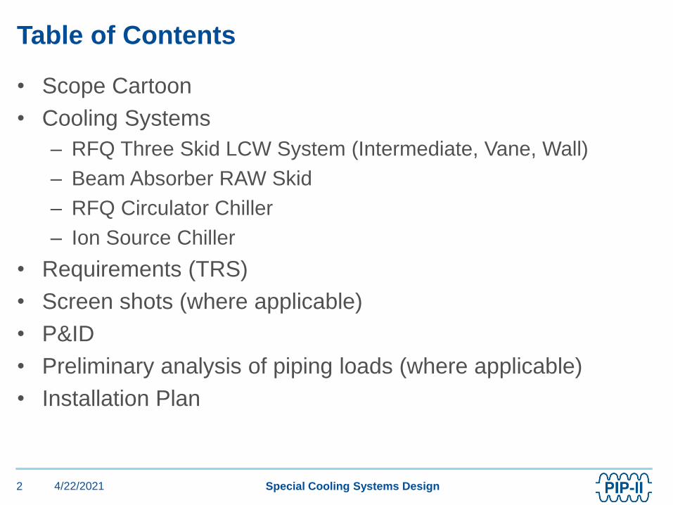
• Scope Cartoon
• Cooling Systems
– RFQ Three Skid LCW System (Intermediate, Vane, Wall)
– Beam Absorber RAW Skid
– RFQ Circulator Chiller
– Ion Source Chiller
• Requirements (TRS)
• Screen shots (where applicable)
• P&ID
• Preliminary analysis of piping loads (where applicable)
• Installation Plan
Table of Contents
4/22/20212 Special Cooling Systems Design

Four Specialized Cooling Systems - Locations
F-37
To Booster
Cooling
Towers
Utility Plant
Utility Bridge
HB650 LB650 SSR1WARM FRONT
END
SSR2
Low Conductivity Water (LCW)
Ion Source Chiller
RFQ Cooling Skids (3)
RFQ Circulator Chiller
Absorber RAW Skid
Process Clean Cooling Water (PCW)
Linac Complex
4/22/20213 Special Cooling Systems Design
RFQ Cooling Skids (3)Absorber RAW Skid
RFQ Circulator ChillerIon Source Chiller

A Partnership of:
US/DOE
India/DAE
Italy/INFN
UK/UKRI-STFC
France/CEA, CNRS/IN2P3
Poland/WUST
RFQ 3 Skid System Design
Maurice Ball/Jerzy (Yurick) Czajkowski
PIP-II LINAC Complex Mechanical Fluid
Systems PDR
April 21, 2021

• Three Separate cooling skids work together as one system
• 304 Stainless Steel and Copper piping material
• Vane and Wall Skids
– Used during PIP2IT operations. Will be reused for PIP-II
operations
– Recirculate cooling water through Vane and Wall areas of the
RFQ
– Heat exchange with Intermediate skid
• Intermediate Skid heat exchanges with 45°F Facility Chilled
Water
• Special flow control valve and flow meter under PLC program
to provide tight +/- 0.5 °F tolerance requirement
RFQ 3 Skid System - Highlights
4/22/20215 Special Cooling Systems Design

• Building Infrastructure shall provide the RFQ Intermediate
cooling water skid according to the following specifications:
• Discharge Pressure = 100 PSIG
• Suction Pressure = 15 PSIG
• Supply Temperature = 70°F +/- 1.0 ⁰F
• Delta T (ΔT) = 21.0 F⁰
• Total Heat Load = 71 KW
• Nominal Flow Required = 49 GPM
• Resistivity = 2 MOhm-CM
• Full flow Particulate filtration at 1 micron
Technical Requirements for RFQ Intermediate Skid
4/22/20216 Special Cooling Systems Design

RFQ 3 Skid LCW System Block Diagram
4/22/20217 Special Cooling Systems Design

• Building Infrastructure shall provide the RFQ Vane cooling
water skid according to the following specifications:
• Discharge Pressure = 100 PSIG
• Suction Pressure = 15 PSIG
• Supply Temperature = 86°F +/- 0.5 ⁰F
• Delta T (ΔT) = 5.0 F⁰
• Nominal Heat Load = 29 KW
• Nominal Flow Required = 65 GPM
• Resistivity = 2 MOhm-CM
• Full flow Particulate filtration at 1 micron
Technical Requirements for RFQ Vane Skid
4/22/20218 Special Cooling Systems Design
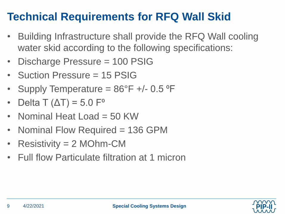
• Building Infrastructure shall provide the RFQ Wall cooling
water skid according to the following specifications:
• Discharge Pressure = 100 PSIG
• Suction Pressure = 15 PSIG
• Supply Temperature = 86°F +/- 0.5 ⁰F
• Delta T (ΔT) = 5.0 F⁰
• Nominal Heat Load = 50 KW
• Nominal Flow Required = 136 GPM
• Resistivity = 2 MOhm-CM
• Full flow Particulate filtration at 1 micron
Technical Requirements for RFQ Wall Skid
4/22/20219 Special Cooling Systems Design

Intermediate RFQ LCW Skid P&ID
4/22/202110 Special Cooling Systems Design
Legend:PT – Pressure TransmitterPI – Pressure IndicatorTT – Temperature TransmitterTI – Temperature IndicatorRT – Resistivity TransmitterDI – DI BottleF1 – Pre-FilterF2 – After-FilterFG – Flow IndicatorPRV – Pressure Relief Valve

RFQ WALL LCW Skid & Intermediate Skid
4/22/202111 Special Cooling Systems Design
Legend:PT – Pressure TransmitterTT – RTD Temperature TransmitterFT – Flow Meter/TransmitterFV – Flow/Temperature Control ValveRT – Resistivity Transmitter

RFQ VANE LCW Cooling Skid
4/22/202112 Special Cooling Systems Design
Legend:PT – Pressure TransmitterTT – RTD Temperature TransmitterFT – Flow Meter/TransmitterFV – Flow/Temperature Control ValveRT – Resistivity Transmitter

• Reusing the Vane and Wall skids from PIP2IT
• After RFQ testing completed, Vane and Wall skids
disconnected and moved to storage
• For PIP-II installation, Vane and Wall skids brought out of
storage and installed in High Bay ground floor in cooling skid
alcove
• Piping manifolds and hose assemblies from PIP2IT operation
reused
• New Intermediate Skid will be built to replace existing skid.
• Once cooling skids, piping manifolds, and hose assemblies
are installed and connected, perform pneumatic and
hydrostatic pressure tests
Installation Plan
4/22/202113 Special Cooling Systems Design

Photo Image - RFQ Vane Wall Skids at CMTF
4/22/202114 Special Cooling Systems Design

Photo Image - RFQ Wall skid at CMTF
4/22/202115 Special Cooling Systems Design

Photo Image - RFQ Vane skid at CMTF
4/22/202116 Special Cooling Systems Design

Photo Image - RFQ Vane Wall Flowmeters at CMTF
4/22/202117 Special Cooling Systems Design

Photo Image - RFQ Intermediate skid at CMTF
4/22/202118 Special Cooling Systems Design

Photo Image - RFQ Intermediate skid at CMTF
4/22/202119 Special Cooling Systems Design

A Partnership of:
US/DOE
India/DAE
Italy/INFN
UK/UKRI-STFC
France/CEA, CNRS/IN2P3
Poland/WUST
RFQ Circulator/Loads Chiller System Design
Maurice Ball/Jerzy (Yurick) Czajkowski
PIP-II LINAC Complex Mechanical Fluid
Systems PDR
April 21, 2021

• Off the shelf portable chiller
• Self-contained
• Air-cooled chiller
• Special supply temperature control needs (83°F)
• RFQ amplifiers cooled separately using PCW System
RFQ Circulator Chiller Highlights
4/22/202121 Special Cooling Systems Design

• Building Infrastructure shall provide the cooling water system,
including supply and return piping, valves, and
instrumentation, for the RFQ circulator and loads according to
the following specifications:
• Discharge Pressure = 100 PSIG
• Suction Pressure = 15 PSIG
• Supply Temperature = 83°F +/- 1.0 ⁰F
• Delta T (ΔT) = 10 F⁰
• Total Heat Load = 29 KW
• Total Flow Required = 20 GPM
• Resistivity = n/a
Technical Requirements for RFQ Circulator Chiller
4/22/202122 Special Cooling Systems Design

PIP-II RFQ Circulator/Loads Chiller P&ID
4/22/202123 Special Cooling Systems Design
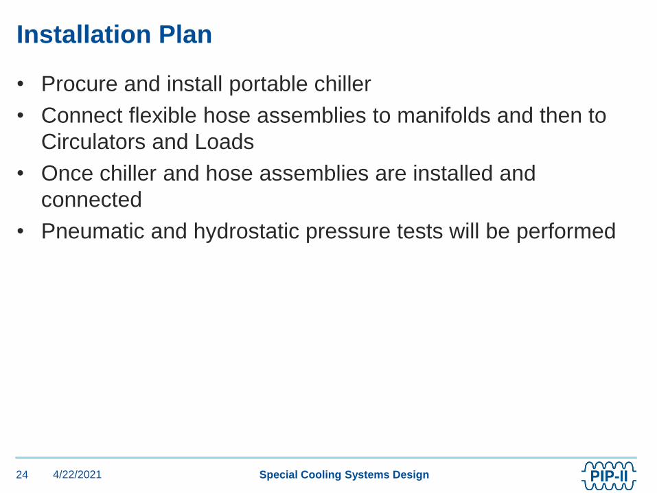
• Procure and install portable chiller
• Connect flexible hose assemblies to manifolds and then to
Circulators and Loads
• Once chiller and hose assemblies are installed and
connected
• Pneumatic and hydrostatic pressure tests will be performed
Installation Plan
4/22/202124 Special Cooling Systems Design

A Partnership of:
US/DOE
India/DAE
Italy/INFN
UK/UKRI-STFC
France/CEA, CNRS/IN2P3
Poland/WUST
Beam Absorber Skid and Piping System Design
Maurice Ball/Jerzy (Yurick) Czajkowski
PIP-II LINAC Complex Mechanical Fluid
Systems PDR
April 21, 2021

• Radioactive Water system
• Cools the Beam Absorber located in the Beam Transfer Line
(BTL)
• Normal Fluid Service
• Nitrogen gas used as tank blanket and to purge Hydrogen
gas from system
• Magnetically driven circulating pump, no leaky seals
• Containment basin located under RAW skid, sized to contain
entire RAW system volume
Beam Absorber RAW Skid - Highlights
4/22/202126 Special Cooling Systems Design

• Building Infrastructure shall design the Absorber RAW cooling
system, including supply and return piping, valves, and
instrumentation for the Absorber according to the following
specifications:
• Discharge Pressure = 100 PSIG
• Suction Pressure = 15 PSIG
• Supply Temperature = 100°F +/- 1 ⁰F
• Delta T (ΔT) = 23.5 F⁰
• Total Heat Load = 25 KW
• Total Flow Required = 20 GPM
• Resistivity = n/a
• Full flow particulate filtration at 5 micron
Technical Requirements for Beam Absorber RAW
Skid
4/22/202127 Special Cooling Systems Design

Beam Absorber Skid and System P&ID
4/22/202128 Special Cooling Systems Design
Legend:PI – Pressure IndicatorTI – Temperature IndicatorLT – Level TransmitterPT – Pressure TransmitterTT – Temperature TransmitterFT - Flow Meter/Transmitter
1 ½” RAW RETURN 123.5 degF
1 ½” RAW SUPPLY 100 degF

• Example of a similarly
designed Absorber RAW
Skid at NML
Beam Absorber RAW Skid – Highlights (Continued)
4/22/202129 Special Cooling Systems Design

Preliminary Analysis Of Designed Absorber RAW
Piping
4/22/202130 Special Cooling Systems Design

Preliminary Analysis Of Designed Absorber RAW
Piping (Continued)
4/22/202131 Special Cooling Systems Design
Primary piping wall thickness (T) exceeds minimum wall thickness (tm) requirements

• Coordinate delivery of RAW skid to Absorber RAW Room
• Supply stainless steel piping interconnecting Absorber to
RAW cooling skid
• Once both skid and piping system are installed and
connected, pneumatic and hydrostatic pressure tests will be
performed.
Installation Plan
4/22/202132 Special Cooling Systems Design

A Partnership of:
US/DOE
India/DAE
Italy/INFN
UK/UKRI-STFC
France/CEA, CNRS/IN2P3
Poland/WUST
Ion Source Chiller and Piping System Design
Maurice Ball/Jerzy (Yurick) Czajkowski
PIP-II LINAC Complex Mechanical Fluid
Systems PDR
April 21, 2021

• Used during PIP2IT
• Will be reused in PIP-II
• Self-contained
• Air-cooled chiller
• Piping manifold will be reused in PIP
• Special supply temperature control needs (70°F)
Ion Source Chiller Highlights
4/22/202134 Special Cooling Systems Design

• Building Infrastructure shall provide the Ion Source LCW
System according to the following specifications:
• Discharge Pressure ≥ 70 PSIG
• Suction Pressure = 15 PSIG
• Supply Temperature = 70⁰F +/- 1.0⁰F
• Delta T (ΔT) = 7.2 F⁰
• Total Heat Load = 12 KW
• Total Flow Required = 14 GPM
• Resistivity = 4 MOhm-CM
• Built-in particulate filtration at 5 micron
Technical Requirements for Ion Source Chiller
4/22/202135 Special Cooling Systems Design

PIP-II Ion Source Skid and System P&ID
4/22/202136 Special Cooling Systems Design

• Reusing the Ion Source Chiller from PIP2IT
• After Ion Source testing completed, chiller disconnected and
moved to storage
• For PIP-II installation, chiller brought out of storage and
installed in High Bay ground floor in cooling skid alcove
• Piping manifolds from PIP2IT operation reused.
• New hose assemblies created
• Once chiller, piping manifolds, and hose assemblies are
installed and connected, pneumatic and hydrostatic pressure
tests will be performed
Installation Plan
4/22/202137 Special Cooling Systems Design

Photo Image - Ion Source Skid at CMTF
4/22/202138 Special Cooling Systems Design

Photo Image - – Ion Source to LEBT Transition at
CMTF
4/22/202139 Special Cooling Systems Design

Photo Image – LEBT to RFQ Transition at CMTF
4/22/202140 Special Cooling Systems Design

Photo Image – RFQ at CMTF
4/22/202141 Special Cooling Systems Design

• RFQ Cooling (Right image)
• LEBT Cooling (Bottom image)
Photo Image – East Wall CMTF Cave
4/22/202142 Special Cooling Systems Design

• MEBT Cooling (Right and
Bottom)
Photo Image - Warm Front End Process Fluids
Cooling at CMTF
4/22/202143 Special Cooling Systems Design