Embed Size (px)
Citation preview

Vol. 130 (2016) ACTA PHYSICA POLONICA A No. 1
Special issue of the 2nd International Conference on Computational and Experimental Science and Engineering (ICCESEN 2015)
Determination of Imbalance Problem in Electric Motorand Centrifugal Pump by Vibration Analysis
R. Kiliç∗
SASKİ General Directorate, Kentpark İçi, PK 144, Sakarya
In this study, general characteristics of imbalance problem in electric motor and centrifugal pumps and thevibrations caused by these faults are discussed. The fact that frequencies would yield vibrations which were causedby imbalance problems was investigated in detail. In addition, the vibration behavior formed by the electric motorand centrifugal pump running in water pumping mode are presented as a sample case. It is observed that theimbalance problem which have occurred in the electric motor and centrifugal pump could be easily determinedusing the vibration analysis.
DOI: 10.12693/APhysPolA.130.487PACS/topics: 43.40
1. Introduction
Solution of vibration problems in the electric motorsand centrifugal pumps is important for proper operationand performance. Excessive vibrations seen in the elec-tric motors and centrifugal pumps shorten the life of themachine and lead to the mechanical fatigue and even todamage of the machine. The causes of these vibrationsin the electric motors and centrifugal pumps may be me-chanical, fluid-borne or electromechanical [1]. Many ofthe mechanical and electromechanical-borne vibrationsare directly related to the machine speed and can bedetermined by vibration analysis [2]. It is necessary tocarry out the measurements in order to determine thesource of vibrations. The source of the vibration can bedetermined by examining the relationships among dataobtained from these measurements in the time and fre-quency domains.
Imbalance is one of the vibration sources in the elec-tric motors and centrifugal pumps. The main causes ofthis problem in the electric motors and the pumps are:defects during manufacturing, corrosion in the pump fan,partial permanent pollution of the pump fan blade, theunbalanced mounting of one of the pump bearings carry-ing the whole loads of pump fan, improper mass distri-bution in the rotor arms and blades of the electric mo-tor, the bending of the pump and electric motor shaft.The imbalance problem encountered in electric motorand centrifugal pumps causes negative effects on pumpefficiency [3]. In this study, the vibrations of an electricmotor and centrifugal pump were evaluated in the timeand frequency domain. As a result of this evaluation,the direction and the frequencies, at which the peaks ofvibration were formed by imbalance, was obtained in thefrequency domain and the effects of these peak values inthe time domain were plotted.
∗e-mail: [email protected]
2. Identification of imbalance problem
The state of equilibrium of all forces formed by the ro-tating machine elements is called equilibrium (balance).Any change in this state of equilibrium creates imbal-ance. Imbalance is the most common source of vibrationseen in machines [4].
Imbalance is a linear problem. If a rotor is unbalanced,it will have the same amount of imbalance throughout thecycle of 360 degrees. Each cycle in the time domain willhave the same amplitude, at the same time, the image ofthe time signal will have a sinusoidal structure [5]. Im-balance may appear in two ways: static and dynamic.In case of static imbalance, centrifugal force is appliedon bearings at 1X frequency. The 1X force here is di-rectly proportional to the square of rotor speed. Imbal-ance forces in electric motors and centrifugal pumps al-ways cause vibration in the manner that there will be 90degrees of phase difference between bearings, tangentialand radial 1X components [6]. This is the definite testof imbalance and it is used for determination of imbal-ance due to misalignment and in analysis of the vibrationplots.
In the vibration analysis, imbalance always createshigh vibration amplitudes at 1X RPM. If imbalance is se-vere, it manifests itself in the frequency spectrum alongwith imbalance at operating speed. These frequenciescan sometimes make it difficult to test the imbalance,however, the existence of the imbalance cannot be men-tioned without any evidence of vibration amplitude at1X RPM frequency. If there is 1X RPM component inthe frequency spectrum, imbalance will be at the begin-ning of the list of probable causes [5].
While analyzing the vibration spectra, vibration peaksshowing imbalance in the radial and tangential directionshould be compared. Vibration peaks in the radial direc-tion will have larger amplitude than the vibration peaksin the tangential direction. The severity of the imbalancewill be indicated by the closeness of these peaks in bothdirections, which are the imbalance indicators, to eachother. Vibration peaks in the axial direction will haveextremely low amplitude [7].
(487)

488 R. Kiliç
Attention should be paid to this topic in the analy-sis of vibration of the motor pumps which are verticallymounted. Since the back part of engine is not mountedon anything, the 1X vibration occurs in the engine.While determining the motor imbalance, 1X measure-ments should be made by firstly removing the couplingand starting the motor alone, in order to isolate the im-balance of the motor from the imbalance of the pump.In this case, the problem is in motor if 1X levels of freeside of the engine are high. Otherwise the problem is inthe pump [8]. The discussed features of the imbalancemeasurement are summarized in Table I.
TABLE I
Imbalance malfunctions dashboard.
Dominant vibration frequencyMeasurement
direction•Vibration peaks at radial and tangential1X RPM, vibration peaks with low ampli-tude and low axial vibration at 2X RPMand 3X RPM.
Radial
•The time signal has a sinusoidal form.•1X RPM peaks should occur in the samedirection on both bearings.•1X RPM peaks in the radial direction aregreater than the 1X RPM peaks in the tan-gential direction
Tangential
•Approximate imbalance values:1X RPM radial > 4 mm/s1X RPM tangential > 3 mm/sLow axial value.If the ratio between radial and tangential isgreater than 0.25 and smaller than 4, thereis an imbalance.
Axial
3. Materials and methods
PREDICT-DLI DCA-20 data collector program for thedetermination of the imbalance problem in the electricmotors and centrifugal pumps and ExpertALERT forVoyager programs were used in this study. PREDICT-DLI DCA-20 data collector system consists of two parts,hardware central processing unit and the software.
By using PREDICT-DLI DCA-20 data collector sys-tem, one or more measurement points can be defined oneach electric motor and centrifugal pump. PREDICT-DLI DCA-20 data collector can make measurementsalong 3 axes or only one axis, the point to be measuredcan be easily identified using a barcode. Measurementcan be made in the range of 40–60 kHz and a 6400-linespectrum can be taken.
ExpertALERT for Voyager program which was usedin the study is composed of two components. The firstcomponent is the program file, and the second sectionis the database where facility information, motor-pumpinformation, the results and report information obtainedfrom measurement are stored. All features of the electric
motor and centrifugal pumps (speed, being horizontal orvertical, the drive unit, etc.) can be introduced sepa-rately to the program.
In our study carried out to determine the imbalanceproblem in electric motors and centrifugal pumps with vi-bration analysis, first the vibration measurement pointsand measurement directions were determined. Determi-nation of measurement points before making vibrationanalysis of electric motors and centrifugal pumps helps todetermine the best data collection points for the analysisand to define the potential sources of the vibration [9].For this purpose, the closest points to the bearings inelectric motors and centrifugal pumps were selected asmeasurement points. While selecting these points, areasof metal to metal joints, painted surfaces, unloaded bear-ing areas, split and cracked bearings and the structuralspaces were avoided.
Fig. 1. Schematic view and measurement directions ofthe accurate measurement points near ball bearings.
Fig. 2. Acceleration detector and mounting pad usedin vibration measurement.
Taking the vibration measurements always in samepoint and directions is very important in terms of stor-ing the vibration data obtained from the electric motorsand centrifugal pumps for comparative purposes and formonitoring the trend curves [10]. The acceleration detec-tor and the assembly block are shown in detail in Fig. 2.Detector sensors were designed to be oriented always in
Determination of Imbalance Problem in Electric Motor and Centrifugal Pump. . . 489
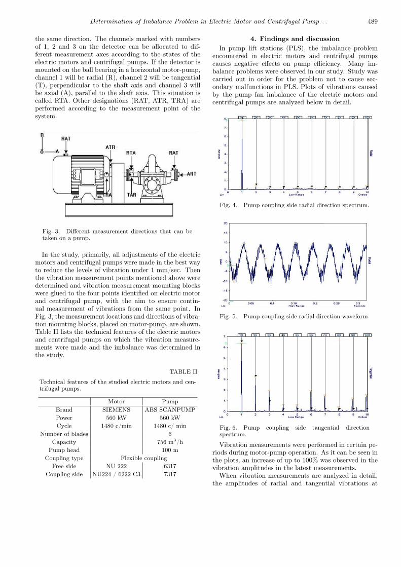
the same direction. The channels marked with numbersof 1, 2 and 3 on the detector can be allocated to dif-ferent measurement axes according to the states of theelectric motors and centrifugal pumps. If the detector ismounted on the ball bearing in a horizontal motor-pump,channel 1 will be radial (R), channel 2 will be tangential(T), perpendicular to the shaft axis and channel 3 willbe axial (A), parallel to the shaft axis. This situation iscalled RTA. Other designations (RAT, ATR, TRA) areperformed according to the measurement point of thesystem.
Fig. 3. Different measurement directions that can betaken on a pump.
In the study, primarily, all adjustments of the electricmotors and centrifugal pumps were made in the best wayto reduce the levels of vibration under 1 mm/sec. Thenthe vibration measurement points mentioned above weredetermined and vibration measurement mounting blockswere glued to the four points identified on electric motorand centrifugal pump, with the aim to ensure contin-ual measurement of vibrations from the same point. InFig. 3, the measurement locations and directions of vibra-tion mounting blocks, placed on motor-pump, are shown.Table II lists the technical features of the electric motorsand centrifugal pumps on which the vibration measure-ments were made and the imbalance was determined inthe study.
TABLE II
Technical features of the studied electric motors and cen-trifugal pumps.
Motor PumpBrand SIEMENS ABS SCANPUMPPower 560 kW 560 kWCycle 1480 c/min 1480 c/ min
Number of blades 6Capacity 756 m3/h
Pump head 100 mCoupling type Flexible coupling
Free side NU 222 6317Coupling side NU224 / 6222 C3 7317
4. Findings and discussionIn pump lift stations (PLS), the imbalance problem
encountered in electric motors and centrifugal pumpscauses negative effects on pump efficiency. Many im-balance problems were observed in our study. Study wascarried out in order for the problem not to cause sec-ondary malfunctions in PLS. Plots of vibrations causedby the pump fan imbalance of the electric motors andcentrifugal pumps are analyzed below in detail.
Fig. 4. Pump coupling side radial direction spectrum.
Fig. 5. Pump coupling side radial direction waveform.
Fig. 6. Pump coupling side tangential directionspectrum.
Vibration measurements were performed in certain pe-riods during motor-pump operation. As it can be seen inthe plots, an increase of up to 100% was observed in thevibration amplitudes in the latest measurements.
When vibration measurements are analyzed in detail,the amplitudes of radial and tangential vibrations at

490 R. Kiliç
1X RPM of motor speed (Figs. 4, 6, 8 and 10) leadus to suspicions that there might be an imbalance prob-lem. The mechanical space and the coupling misalign-ment produce vibrations at the same frequency.
Fig. 7. Pump coupling side tangential direction wave-form.
Fig. 8. Pump impeller side radial direction spectrum.
Fig. 9. Pump coupling side radial direction waveform.
When looking at the spectra of the vibration measure-ments taken from both free side of the pump (Figs. 8and 10) and coupling side of the pump (Figs. 4 and 6),the amplitude value at 1X RPM frequency in the vibra-tion plots in radial direction is greater than the ampli-tude value at 1X RPM frequency in tangential direction,
Fig. 10. Pump impeller side tangential directionspectrum.
Fig. 11. Pump impeller side tangential directionwaveform.
Fig. 12. Comparison of pump coupling side radial di-rection spectra.
Fig. 13. Comparison of pump coupling side radial di-rection spectra.

Determination of Imbalance Problem in Electric Motor and Centrifugal Pump. . . 491
Fig. 14. Comparison of pump impeller side radial di-rection spectra.
Fig. 15. Comparison of pump impeller side tangentialdirection spectra.
which increases the likelihood of imbalance. Moreoverthe measurements of amplitude values in the radial di-rection taken from both sides (Figs. 4 and 8) are greaterthan 4 mm/s, which reinforces this possibility. In thiscase, vibration plots should be examined in the frequencyand time domains. When looking at the vibration plots ofpump free side and coupling side in the time domain, thesignal has a sinusoidal structure (Figs. 5, 7, 9 and 11).This situation is exactly the evidence of the imbalanceproblem.
In Figs. 12–15, the changes of the vibration amplitudesin the radial and tangential direction of both pump freeside and pump coupling side can be observed during theoccurrence of malfunction.
After this discovery, the pump was stopped and thenecessary intervention was performed. When the pumpwas opened, it was observed that two of the fan bladeswere corroded. It was seen that this imbalance wascaused by the corrosion on pump blades.
5. Conclusions
Imbalance is one of the major problems encounteredin the electric motors and centrifugal pumps. In orderto discover the imbalance by the vibration analysis, thefollowing points should be noted.
• The points to be measured on the system must bedetermined accurately.
• Reference measurement points should not bechanged.
• While detecting the imbalance by vibration analy-sis, results should be viewed in both, the time andvibration frequency domains.
• According to the importance of the measured sys-tem, the vibration analysis should be done usingdetermined reference values.
• Permanent measurement points must be deter-mined for critical electric motors and centrifugalpumps. Online measurement must be made atthis points and it must be saved to the database.The recorded data must be evaluated by the soft-ware to do the necessary analysis.
References
[1] N. Aktürk, R. Gohar, Proc. Instn. Mech. Engrs.212, 101 (1998).
[2] J. Piotrowski, Why Shaft Misalignment Contin-ues To Befuddle And Undermine Even The BestCBM And Pro-Active Maintenance Programs, www.maintenanceresources.com, 2001.
[3] B. Leimkuhler, Vibration Monitoring of Electric Mo-tor Bearing, SKF Condition Monitoring, Inc. Tech-nical Paper CM1007, 1999.
[4] S. Orhan, Teknoloji 3, 41 (2003).[5] W. Victor, Machinery Vibration Measurement and
Analysis, McGraw Hill Book Company, 1991.[6] J.I. Taylor, The Vibration Analysis Handbook, Vibra-
tion Consultants, 1994.[7] D.W. Gelen, Introduction To Machine Vibration, DLI
Engineering Corp., 1993.[8] R.L. Eshleman, Machinery Vibration Analysis II,
Vipress, 1996.[9] S.R. Bognatz, Alignment of Critical and Noncritical
Machines, www.bently.com, 2000.[10] D. Yu, J. Cheng, Y. Yang, Mech. Syst. Signal Proc.
19, 259 (2005).