Embed Size (px)
Citation preview
59 AO
Special Report ETL.SR-71-2
UTILIZATION OF A PHOTOGRAM WETRIC FAaUTY (PF)
IN HUMAN ENGINEERING LABORATORIES BATTALION ARTILLERY
TEST NUMBER TWO (HELBAT U)
by
1LT Rkhard E. Sduieck
August 1971
AffnmtA lor fakkk rdtme: &tA*6tm wdmikti
D O C u
im 1 ♦ «•;.--<;.•.♦< i'
NA1IOHAL TECH^:CAL INFORMATION SE^VsCE
US ARMY ENGINEER TOPOGRAPHIC LABORATORIES FORT 8ELV0IR, VIRGINIA
^
laEtsioü ST
A D^troy this report when no longer needed. Do not return it to the originator.
The citation in this report of trade names of commercially available products does not constitute official endorsement or approval of the use of such products.
LSJCMSSIHED S^cuntyCUmMÜcmücm
DOCUMENT CONTROL DATA d & D (JiemHr elmMHIeamm «I Uttm. fco* 0/ ehittmtt mud indmjjng mimoimiiait mumt b* mtt^m* whmn th* owll report IM elmmiHfd)
S£. RCPOMT bCCUNlTV CkASSIPlC* TlON
I'ticlassifirtl t. OftistNAriHO ACTIVITY (Cofpormlm tmOmt}
V. S. Army fjigiiitfr Toftographic LaltioraltiirifS Fort »ilvoir. Virpnia 22060 lb. 6ROUP
N/A 9- MCROMT TITLC
UTILIZATIUN OF A PHüT(K;RAMMFTKI(: FACILITY (IT) IN HI MAN KMJINKKKIVi LABORATORIES BATTALION ARTILLKRV TKST M MBKR VM) (IIFLBATII)
4. OCICRIPTIVC NOTCSfTVy« of Mporf MtT jbcli**^« Aiftaj
Spcda! Rrpur1! >. SETWoigi (ntmtmam, mSSSSi SUSS» 55?
Richard E, Schn«"ck
• MK^OMT DATS
AiigM 1971 7m. TOTAL NO. Or PA«C5
24
7b. ».o OF «CF»
•a. OmeiMATOA'S MC«>ORT NUM»CRiS)
•.»WUCCTNO. 4A662707IJ853 ETLSR7I2
OTHCA ACPONT MO<r> (Atf »*^ WiMlft>i* OlAf «Mr *• •»•»01*4
!•- OttTMauTtOM STATSfJCtjT
A|)|iro%i*ti for pubSic nlra» , distrihutiun uitlimited.
II- SUP^LCWCMTARV MOTKS 12- SPONSORINQ MILITARY ACTIVITY
I . S. Arm» Ktifrinrrr 'iiifiogruphir l.iit»onilorir.' Fort Ifclvoir. Virginia 22000
• a. ABSTRACT
This nrporl rovers t^ts of Ihc tapabililv of phoCogrammetnt- cquipmriu antl tct Imiqiif > lo provirlt- pusilioiuJ «lala rt-quirt'd by Field Arlillen opiTations. Commereial grade photogramiuetrii- iMpiiftiiieiil nas a^emUed and installed by Ihe t. S. Army Eiijdiitrr Topographie LaboraU rie.^ and HJ> operal4*d U\ nilistcd personnel from the 30th Engineer Battalion (BT). The test was designed and implernenled IK Ihr ilninan Engineering Laboratories in eoneert with an organizational readiness training lest imoKiiig Ih« I'irst Vrmorfd Division Artillery at Fort Hood, Tcxa». during February 1971. Results of ihr total testiugrffort. Human Engineering Uboratories Battalion Artillery Test Number Two (HKLBAT II). an- reported in a separate documenl by the Human Engineering Laboratories, Aberdeen, Maryland.
The high visibility given the concept, equipment, and operations of the Pliolo^animctri« Kaeilily (IM) during HELBAT II resulted in subjective evaluation at all levels of command which wa* sijiniliumf in llu- general Jiereplanee of tin- PF*s potential for military support. Sufficient data for numerical analvsis were
gathered only for Forward iJbserver and target positioning exercises, but other polenfitll a|)|)lirali<m> \srrc examined. Terf data indicate a 30% improvement in the capability to locate Forward Observer* a« compared with the doctrinal map spot techniques, but a degradation in the abilih to position targets wa* noted.
■%#% MM 4 M *§*% S»«RI AC«» oo fomm i4Ti. I JAM M, VKr i «•« M14 /^ •••ei.KT« row AHMT US«.
). «MICH IS
23 UNCLASSiriKI)
8«curity ClasalflcAtion'
INCLASSIKIKI) Security ClassifjcaUon
KEY WORDS
INCLASSIKIKI) 24 Security Clsssificstion
1 3-4 -;t4.3(ts- Kt Belvoir
l). S. ARMY ENGINEER TOPOGRAPHIC LABORATORIES FORT BELVOIR, VIRGINIA
Special Report ETL.SR-71-2
UTILIZATION OF A PHOTOGRAMMETRIC FACILITY (PF) IN HUMAN ENGINEERING LABORATORIES BATTALION ARTILLERY
TEST NUMBER TWO (HELBATII)
Project 4A662707D853
August 1971
Distributed by
The Commanding Officer U. S. Army Engineer Topographic Laboratories
Prepared by
1LT Richard E. Schneck Surveying and Geodesy Divisic n
Approved for public release; dLstribution unlimited.
FOREWORD
This report was prepared under the authority of Project 4A662707I)853, Mapping and Geodesy.
Hie report was prepared by 1LT Richard K. Schneck, Research and Development Coordinator, assigned to the Surveying and Geodesy Division, under the direction of Mr. Melvin Crowell, Jr., Chairman, ETTL STAND Working Group, and under the generaJ direction of Mr. Gilbert G. Lorenz, Technical Director, Engineer Topographic Labora- tories, U. S. Army Topographic Command, Fort Belvoir, Virginia.
Testing activities reported in this document were coordinated with Mr. Gary L. Horley, Aberdeen Research and Development Center (ARDC), Human Engineering Laboratories (HEL), Aberdeen Proving («round, Maryland.
During the conduct of IIELBATII, the equipment system was operated by SP5 Warren E. Smith and SP4 Alan F. Chamberlain, 30th Engineer Battalion Rase Topo. LTC J. R. Lund, Commanding,
Configuration and acquisition of the system equipment were accomplished primär- ily through the efforts of Mr. F. R. Norvcllc, a member of the STANO Working Group. Engineer Topographic Laboratories (ETL).
Personnel using the graphic materials during the conduct of the HELBAT II Tests were provided by the First Armored Division Artillery, Colonel R. (J. Trefry, Commanding.
in
SUMMARY
This report covers tests of the capability of photogrammetric equipment and tech- niques to provide positional data required by Field Artillery operations. Commercial- grade photogrammetric equipment was assembled and installed by the U. S. Army Engi- neer Topographic Laboratories and was operated by enlisted personnel from the 30th Engineer Battalion (BT). The test was designed and implemented by the Human Engi- neer! ; Laboratories, Aberdeen Research and Development Center, in concert with an organizational readiness training test involving the First Armored Division Artillery at Fort Hood, Texas, during February 1971. Results of the total testing effort, Human Engineering Laboratories Battalion Artillery Test Number Two (HELBATII), are re- ported in a £?parate document by the Human Engineering Laboratories, Abeideen, Maryland.
The high visibility given the concept, equipment, and operations of the Photogram- metric Facility (PF) during HELBAT II resulted in subjective evaluation at all levels of command which was significant in the general acceptance of the PF's potential for mili- tary support. Sufficient data for numerical analysis were gathered only for I orward Ob- server and target positioning exercises, but other potential applications were examined. Test data indicate a 30% improvement in the capability to locate Forward Observers as compared with the doctrinal map-shot techniques, but a degradation in the ability to position 'argots was noted.
ii
CONTENTS
Section Title Page
SUMMARY ii
FOREWORD iii
ILLUSTRATIONS v
I INTRODUCTION
1. Purpose 1 2. Background 1
II INVESTIGATION
3. Test Site 3 4. Equipment Description 3 5. DataBase 7 6. Graphic Materials 8 7. Training 8 8. Operational Procedures 12
III DISCUSSION
9. General 13 10. Data Analysis 14 11. Test Results 15
IV CONCLUSIONS
12. Conclusions 22
IV
ILLUSTRATIONS
Figure Title Page
1 Photogrammetric Facility Components 4
2 PF Field Secup 5
3 Photopac Index Photograph 9
4 Photopac Enlargement 10
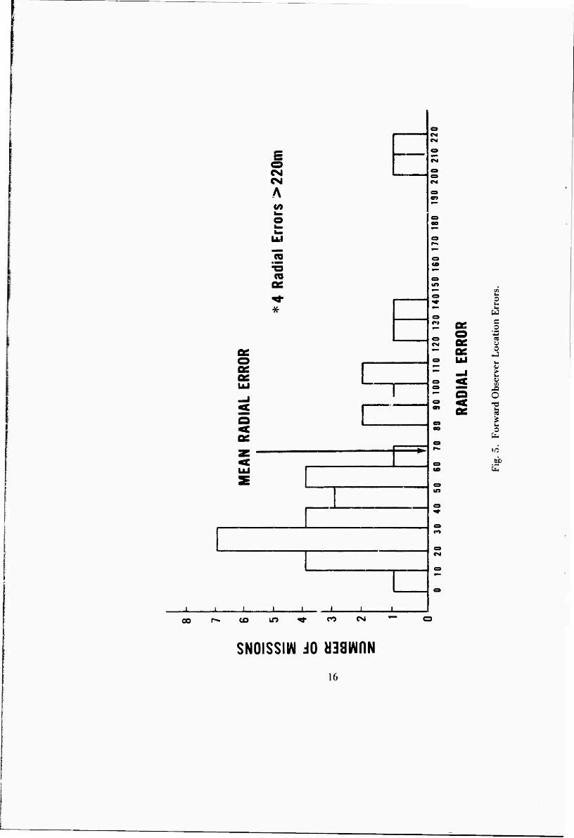
o Forward Observer Location Errors 16
6 Target Location Errors 17
UTILIZATION OF A PHOTOGRAMMfcTRIC FACILITY (PF) IN HUMAN ENGINEERING LABORATORIES BATTALION ARTILLERY
TEST NUMBER TWO (HELBATII)
I. INTRODUCTION
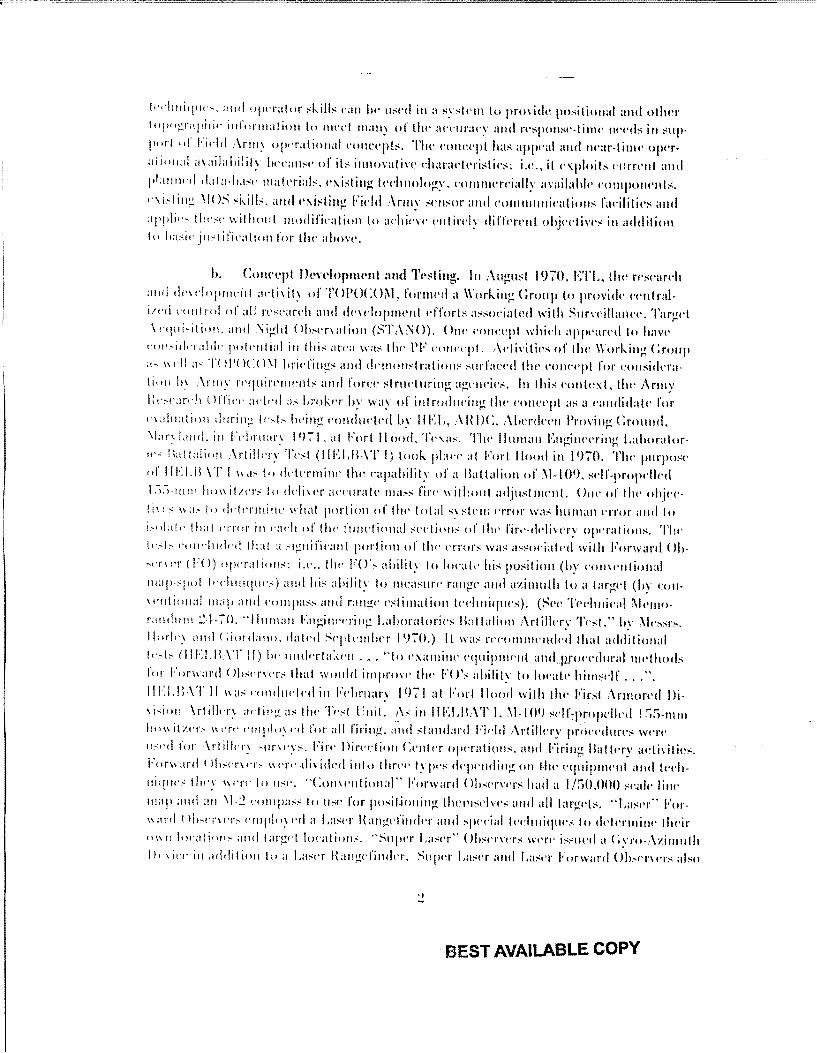
1. Purpose. This report examines the results of the utilization of a Photogram- metric Facility (PF) supplied by the U. S. Army Engineer Topographic Laboratories (ETL) for the Human Engineering Laboratories Battalion Artillery Test Number Two (HELBAT II) which was conducted at Fort Hood, Texas, during February 1971. The primary purpose of ETL's participation in HELBAT II was to determine whether photo- grammetric techniques and equipment could be effectively used to improve the position- ing capabilities of the Field Artillery.
2. Background. The U. S. Army Topographic Command (TOPOCOM), in the course of meeting the mission to provide positional and other topographic support to the Field Army, has become involved in the creation of new concepts for the generation of modern topographic materials. The new concepts permit a time-phased topographic readiness capability according to world-wide threat analyses and base-plant production capacity. Implementation of these concepts is predicated upon the availability and pro- cessing of select imagery, known as data base materials, used in CONUS based facilities.
a. Photogrammetric Facility Concept. It occurred to TOPOCOM that there was an opportunity to exploit these same data base materials and related base plant operational technology for direct application to Field Army requirements. The generalized concept is contained in ETL Technical Report 56-TR, "Photogrammetric Applications to Field Artillery," by Messrs. Eugene P. Griffin, Donald R. Barnes, and James E. Stillwell, dated March 1970. The theme of this concept stresses the points that data-base materials, available by virtue of the TOPOCOM mapping missions, can be made available to Field Army users; that data-base materials can be used in the field employing standard photogrammetric techniques developed in conjunction with base plant production procedures; that commercial-grade photogrammetric equipments are available and suitable for accommodating the data-base materials; that the data-base materials are of such scale and resolution characteristics that when used with the com- mercial equipment and standard photogrammetric techniques an entire Division area of responsibility can be attended in a single "model" setup; that present CON ARC train- ing exists for teaching the skills necessary to operate the photogrammetric equipment and, in fact, is employed in the standard training of Engineer Topo Units; that the state of commercial-grade mini-computers is such as to enable a reasonable dimensional con- figuration, memory size, and operating speed compatible with Field Army operational objectives; and that such data-base materials, photogrammetric equipment, computers,
1
;=cccc.=c================================
k··hnitpw:-. and opnalor :-:kill~ t"<lll lw u:-:t•d in a sy;;lt•m to providt~ positional and other
fopogr;•pili•· infonnaliun to llH'd many of tlw at·t·ura•·y ami n·sponst•-tinw m·t•ds ill sup
purl of Fidd .\nn: o1wratioual t·onct·pts. Tlw t'ollcl'pl has appt·a! and IH'ar-timt· opcr;tiion;d ;nailahdit; lw\'arr::t• of it~ innovative dwrat·kristi<'s: i.t•., it <'\ploits t'IIITI'Ill and
!•larrrwd da!a-ha:'t' rnalt'rial:-:. t'\istirw lt•duwltwv. t'Oilltlll'rriallv availahk t'OHI(HliH'Jrts. ,.... ,...._ ..
,., i."l itt~ \!()~;;kills. and t'\i~titl" Field :\rrm· st~n:->or and t'OIIllllllttil'alion:-> fa('ilities and . ~ . ;ippli•·- tlw:'t' without modifi('ation to :whit'\t' Pnlirl'!y difft•rt•nt objcdin·" in addition lo l>a,;i•· ju:-'1 ifit·ati!Hl for the above.
h. CotH't•pl lh•n•lopnwnt and Tt•sting. In :\ul!ust 1970. ETL, tlw rPst'<m·h
<!ltd dndnpnwirl adi,ity of TOPOC0\1, fornwd a \\'orh.irrg <:roup to providt· !'l'rrlralilni I'Utt!rol of all rc,;l'ardt and dt·\doprnent t·fforts a;;soeialetl with SmveillatH·e. Targd \ •·cpti~i!ion. and :\ighl Oh,.wnation (;-';'I':\ NO). On•· conct•pt which appeared to havt•
l'lll!•idn;dd·· pokntial in this <trt•a wa~ tlw PF C'OIH'c·pt. ,\l'!ivilit•s or tht~ Working Croup "' 11 1·ll a~ T( )!'( H :( l\1 l>ridirrg~ and dt•mon:-<lralion:-< ,.;mfact·d tlH• t'otwt·pl for corrsidnalitHI h1 .\rn1~ n·quircnwnts and fon·t• :->tnlt'turing ag!'rrdt•,.;, In this t•onkxL tlw Army lk~1·an·lt ( lffin· ac-lt-d ;~,; kok1·r by way of introdttt·in~ tht' eonl't'pl as a t·arrdidatt· for na!ttation durin;_! It•,;[.; !wing condw·tcd by IIEL, ABDC, ~\berdt•t•n Proving C:round, \l;~r: land. i11 Ft·hntary I 1)71. ;d Fort II ootl. Tt·:~.a:'. Tlw llunwu EngintTring Lahoralorw< Hal !<!lion \rtilkry Tt',;l (II ELIL\T I) took plat·t· at Forl llood in I 970. Tlw pmpo .. ·w
of 111-:l.n \T I'"'" 1., ddnmirw llw t'apability of a Ballalion of l\1-101), ,;df-propdkd l.i.i ltltll lt•JIIit;.n,.; to ddi11'1' ;wt·uralt• 111a,;:-; firt· 1\ithottl adjtt!'tllrt~tll. One of tlw ohjt•t·!ill'" 11<1.• to ddntnittt• \•lt;tl p•>rlion of tlw total :-:y:-:lt·rn t•rror was hurnan nror and lo
!•olak !lt:tl l'tTor in f·;1ch of llw funl'tional ,.:t•<·tion,.: of llw l'ir,·-tklin·r; op••r:tlion,.:. Tlw l•·,.f,. •·ondt11kd !Ira! a ,.;ignifit·ant portion of tlw nror:-: was a;;:->ot·ialt'tl with Forward Oh,._n, n ( H l) npn;il io11,:: i.,· .. tlw FO',.: ability to ltwak hi;; position (by t'ottwttlioual
tnap·,.pol !t·chniqrw:-:) and hi:-: ahilit: to mcasurt· rattgt· and azimuth to a targt'l (by t:ou
'''nlional map ;nJtl t·ompa,.;:-; attd rangt· t•;;limation ll'..!rniqul's). (~l't' TPt·hnical \lcrrro· r:nulurn ;!.J.-70. ··Jiunwn E11~irwning Lalmratorit·:-: Baltaliott Arlillt·ry 'J',·,-r." by \lt-s:-:rs. ll"rl•·; and ( :iordano. datt·d St·plt·mlwr I 1)70.) IL wa;-; rt'I'OIIllllt'tHicd that additional
lt·•t:- <111·:!.11.\T II) lw tttl!h'l'ta:,,.,t ... "to <'Xalnittt• <'<flripml·nl and!lfOt'l'duralnwtii<Jds for Forw;~rd 0},,-n,n,.; that wotdd imprmT tlw FO\ ability to ltwaLt• hirn:-;df ... ".
Ill-:! ,I\ \T ll 11a,.: •·•~trdtwlt'd in Ft·lmtan !1)71 at Fort llood with thP Fir;-;1 Annorl'd l)j.
,j,..ioll \rttlln~ ading ;1,: tiw Tr·:-:1 l 1ttrl. 1\!' in IIELIL\T L \1-LO'J ,:l'lf:propcllt·tl ! :iS-nun Ito\' itzn• lilT'' t'I!Jf'l"~ ··d for all firing. and standard Fit·ld Artillny prot·t·dnn·s wne ~~~~·d for \rtilln; 'lirlt'.""· Fin· Din·dion C<·ntn opnations. and Firing Ballt'ry activities. Fon' ani t lh:-'1'!'\t'r~ 1\Tf(' ~li,idc·d into tlm·f' lyjH's dqwwlinf,': on 1-lw equipnwnt and lt·ch
lti:ptt'" tl~t·y ~~··n· lo ll:'t'. "Conwntional'' Forward Oh:'<TVI'rs had a I /:)0,000 :"r:dt· li1w tnap ;111d an \1-:.: t·ornpa"'' !o tt:-'1' i'or po.~it.ioning tht'l'l:->dvc•s mtd a!ltargt'l:->. ''La:-;n"" For
\\;Jrrl t ll•~rnn.- t·mplo: •·d a Lasn 1\angl'findn and ='P~'~'ial l<'clrniqtw,.; to d<'ft>rnri1w th1·ir Ill\ I! lol'aliorl- anrl !argl'! location.•. ··~lqwr La,.;n" ()b:"t'J'\'1'1';; WCI'I' i ... StH·d a c:yro-Azimuth llni•T in ;1rldition to <1 La~n Hangdindn. ~tqwr La,-t•r and Las.·r Forward ()!J,-,·nn,; al,.;o
BEST AVAILABLE COPY
c•.-:limale-d !ildr local ions ancl targd locations for :til missions using a map a!Hit·olll(Ht~s. l•:adr of !lw fo·rr Ballalions l!·sll·d wus in tlu~ fidd ahoul :.!~1 davs. and tlw Forward ( )f,. snn·rs mo 1'1•d I o III'W positions llm~1: I i mes d11rin~ this JHTiod. •
Throug:h t:ollaboratioll hetwt'l'll IIEL and ETL. a PF was suhj1Tkd lo l'valualion dming Jflo:LBAT II for it~ potential Fidd Artillery application:- and, slw«·iric·· ;dly. for its polt'ntial to reduct• llw ~~rrors in llw FO's ability tc1 locak hirmwlf, llwn·h: irnprminr.; lh<· df<·<:livcnt•ss of Arlilll'ry fire.
II. IN V ESTICATION
;3, Test SitP. IIELBNJ' II was <·ondui:kd on thl' firin~ range at Fort llood, T<·xas. i\!1 firing during th<' test was condw:t<~d in the w<·stcrn half of llw rtiiiJ.!t wilh tht: FO's oct·11pying: ol):-:!'r\'alion po . .;fs locat<>d on hills )i\lrroundill).!; thl' Impact Zorw. '!'It~· lotal <IIT<I of opnatiorti' <'OVI'I'«'d appr·oxirrwtdy 10 l1y 14 kilornd1:rs. Tlw PF wa;o; posiliotwd <1!1 \lilnninl! ~lotrnl<lin at t!w WPslcrn <"d~~~ of llt1~ Impact Zorw.
All <IITU!'acy analy:-:1~;-; for IIELBAT II opnations we'IT has1:d upon fourlhordiT •\ri illny snrve·ys.
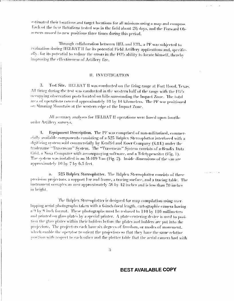
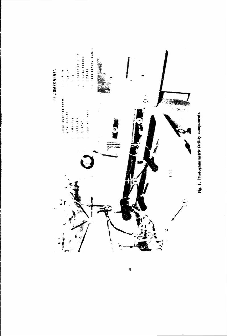
:J.. Equipment Descriplion. Tlw I'F was <·onrprhwd of non-militnrize1l, cornmn-~·ially availabll· compmwnts consisting of a :'i2S Balplcx Stl'rPoploltcr interfa<·<·d with a digitizin).: ,.;ysl<'lll sold cotnnwrTially hy Kmrff,·l and Esser Company (K8d•:) rrndn llw trad<"nanw "Travt•rscan" Sysl<·m. Tlw "Trawrs1·an" System consists of a-4-kndix Data (:rid. a :'\ova Computer with :tt'I'Onl(lllll)'ing sol'lwan:, and a Tcl<~typnwril!•r (Fig:. 1). Tlw syslc-nl WHO' insiHIIc·rl in an ~1-100 Van (Fig. 2). lnsidP dimeni->ions of lh<" van an· appro:-.inrakly I 0 by 7 by o.S f('pt,
a. 52!) Balplex Stereoploth~r. Tlw Balph:x S!cn:oplolln coni->isls of lhn·1· pn·1·i;;ion projc<·tors. a support l·ar and frame, a tra<:ing surface•, and a lr:wing tabk. Tlw instrunwnl ot"!'Upic'.~ an nn·a approxinrutdy !i(> l>y 11·2 irwlws and is k:-:s than iO irwlw:-in lwi~-!111.
Tl~t· 1\:dplt·x SliT('oplollt•r is <ksign<·d for 111ap cornpilulion usif1g owr· lilpptn~ ;wri<ll pho!og:raplt:-; lak!'n with :r (J-indr·f'(lcal knl!th. l'arlogruphie !'llllll'nt having a 1
) h; 4J iwh formal. Th~·s«' plwlographs !lilt"! he~ ITd!H~t·d to I 10 by 110 rnillimdcrs and printed on ~!its-; plait';-; hy a spt'i:ial prinlt'r. A plah··t't'nlcrin~ dnit·<· is usctllo posit inn llw gla:.::.: plates within their lwldns ht'fon~ lh1~ plall's <UHI holdns .ar<' put into llw pr"jt•t•lors. Tlw projiTinr:- t•ach havl' six dq!;I'I'I'S of f'n·Pdom, or modt•s of 1110\'!'rrtl'lll.
\d:idt t•rwbk Ill(' opn;1(or lo oril'nl llu· pmj~·~·t·m.~ ~o llwl I hey hav1· llw sanw rTlaliv<· position with rt'.~jH'I'I lo c•ad1 otlwr and !Itt• plolln l:tl.!<· th:tl tlu• ;wrial ranwra had with
:I
BEST AVAILABLE COPY
• s
1 r^
I
^
a. 3
2
a.
n'spt rt lo thf ground when the photographs were taken. The projected imagery from the overlapping photographs can then form a 3-dimensional stereomodel of the original photoiTaphs.
The operator achieves a stereo view of the terrain photographed by us- ing a special viewing system called the Stereo Image Alternator (SIA). The effect of the SIA is to permit only one eye to see an image from only one projector at any instant. This is accomplished by using synchronous motors to rotate slotted cylinders. By alter- nating the images viewed in this manner, the operator is provided a stereoscopic view of the terrain photographed.
The operator uses a tracing table for making 3-dimensional measurements in the stereomodel. The table contains a horizontal surface (platen) on which the pro- jected imagery is viewed and which has at its center a small hole that is illuminated from below to serve as a reference dot for measuring the stereomodel. The reference dot can be moved horizontally by moving the entire tracing table, and the dot can be moved vertically by means of a knob on the back of the tracing table which causes the platen to be raised or lowered. Horizontal positions can be recorded on the tracing surface by means of a pencil lead which is located directly below the reference dot.
b. Traverscan System. The Traverscan System consists of a Bendix Data Grid, a Nova Computer, a Teletypewriter, and accompanying software. It is, for the most part, mechanically independent of the stereoplotter. There are two items which are attached directly to the tracing table. One is a Z-shaft encoder which measures the elevation of the tracing table platen. This value corresponds directly to sea level eleva- tions in the stereomodel. The other item is a cursor which Is mounted at the base of the tracing table and is centered on the reference-light dot on the platen. This cursor emits an oscillating signal which is picked up by the Bendix Data Grid.
The Bendix Data Grid is used to replace the conventional table-top sur- face of the stereoplotter. and its function is to sense horizontal coordinates taken from the stereoplotter. As the cursor, which is mounted on the tracing table, moves across the lop of the tracing surface, the signal which it is emitting is picked up by a matrix of wires which is embedded in the Data Grid. The position ot the cursor with respect to the Data Grid is digitized to a precision of 0.001 inch, and these values correspond to horizontal positions in the terrain model.
The X, Y, and Z digitized signals are supplied to a Nova Computer which provides a 2-dimensional rotation, a translation, and a scaling operation to express Data Grid coordinates from the Stereomodel in terms of UTM coordinates and sea level eleva- tions. The software also provides a polar mode of operation where the operator can de- termine the range and azimuth between any two points in the stereomodel.
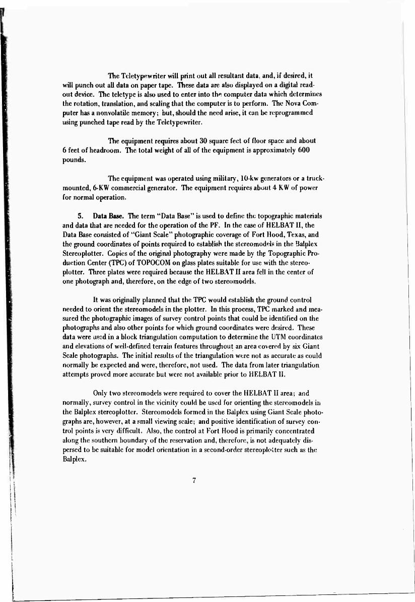
The Teletypewriter will print out all resultant data, and, if desired, it Hill punch out all data on paper tape. These data are also displayed on a digital read- out device. The teletype is also used to enter into the computer data which determines the rotation, translation, and scaling that the computer is to perform. The Nova Com- puter has a nonvolatile memory; but, should the need arise, it can be reprogrammcd using punched tape read by the Teletypewriter.
The equipment requires about 30 square feet of floor space and about 6 feet of headroom. The total weight of all of the equipment is approximately 600 pounds.
The equipment was operated using military, 10-kw generators or a truck- mounted, 6-KW commercial generator. The equipment requires about 4 KW of power for normal operation.
5. Data Base. The term "Data Base" is used to define the topographic materials and data that are needed for the operation of the PF. In the case of HELBATII, the Data Base consisted of "Giant Scale" photographic coverage of Fort Hood, Texas, and the ground coordinates of points required to establish the stereomodels in the Balplex Stereoplotter. Copies of the original photography were made by thp Topographic Pro- duction Center (TPC) of TOPOCOM on glass plates suitable for use with the stereo- plotter. Three plates were required because the HELBAT II area fell in the center of one photograph and, therefore, on the edge of two stereomodels.
It was originally planned that the TPC would establish the ground control needed to orient the stereomodels in the plotter. In this process, TPC marked and mea- sured the photographic images of survey control points that could be identified on the photographs and also other points for which ground coordinates were desired. These data were used in a block triangulation computation to determine the UTM coordinates and elevations of well-defined terrain features throughout an area covered by six Giant Scale photographs. The initial results of the triangulation were not as accurate as could normally be expected and were, therefore, not used. The data from later triangulation attempts proved more accurate but were not available prior to HELBAT II.
Only two stereomodels were required to cover the HELBAT II area; and normally, survey control in the vicinity could be used for orienting the stereomodels in the Balplex stereoplotter. Stereomodels formed in the Balplex using Giant Scale photo- graphs are, however, at a small viewing scale; and positive identification of survey con- trol points is very difficult. Also, the control at Fort Hood is primarily concentrated along the southern boundary of the reservation and, therefore, is not adequately dis- persed to be suitable for model orientation in a second-order stereoplotter such as the Balplex.
As aii expedient, it was decided to triangulate the necessary control data us- ing the AS-11A stereoplotter. The AS-l IA is a first-order instrument and it has a zoom optical system which permits large scale viewing to aid in the point identification pro- cess. The two stereomodels that covered the HELBAT II test area were oriented in the instrument to survey control points that could be identified on the photographs; and with this accomplished, the instrumental coordinates of other well-defined and well- dispersed terrain features (road intersections primarily) were read and recorded. The instrumental coordinates of the survey control points were compared with their known values to determine the transformation required to convert instrument coordinates to I TM values. This transformation was then applied to the othe* unknown points (15 in all) to determine their UTM coordinates. These data were used during HELBAT II to control the stereomodels in the Balplex Stereoplotter.
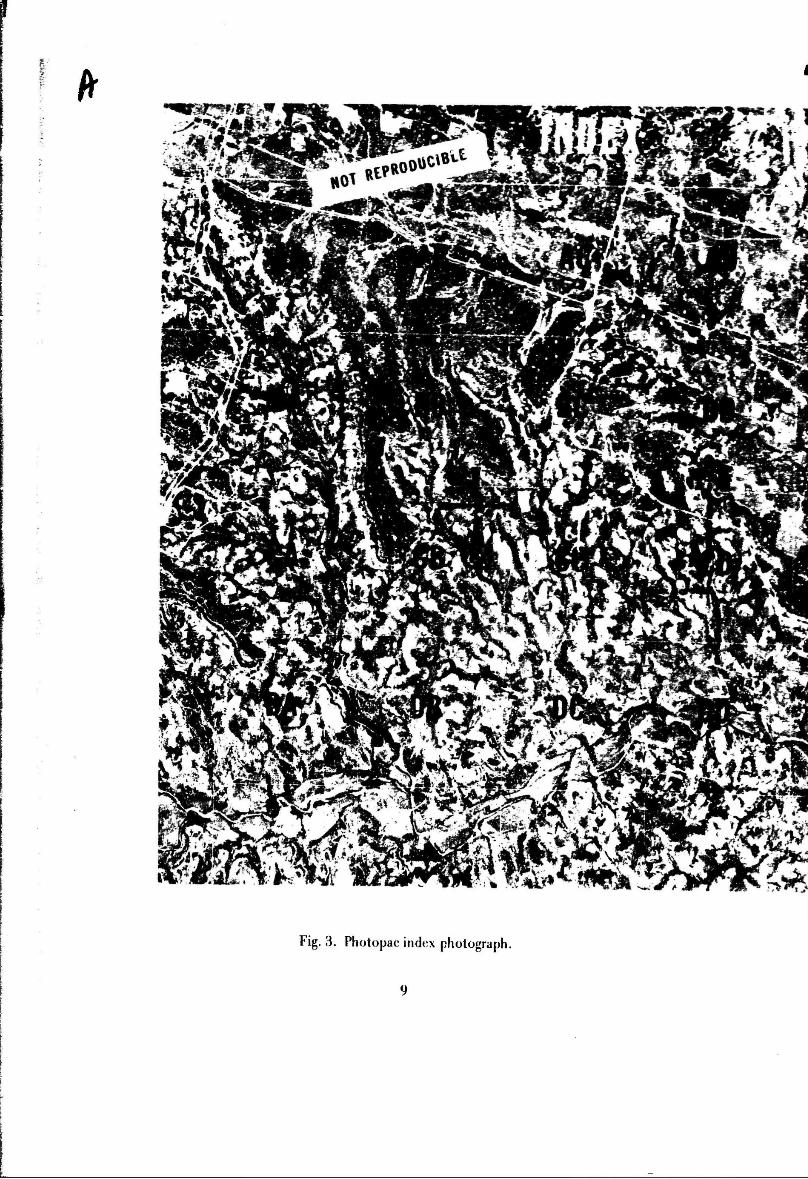
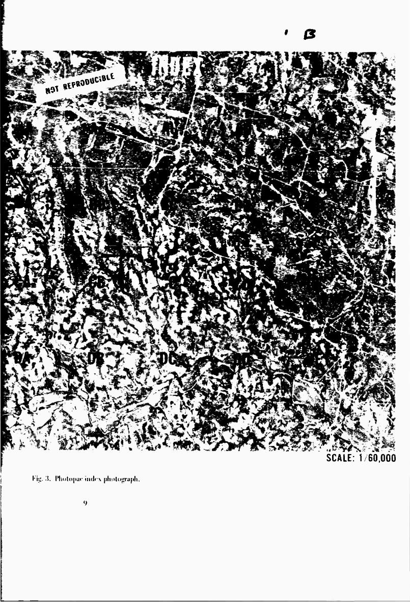
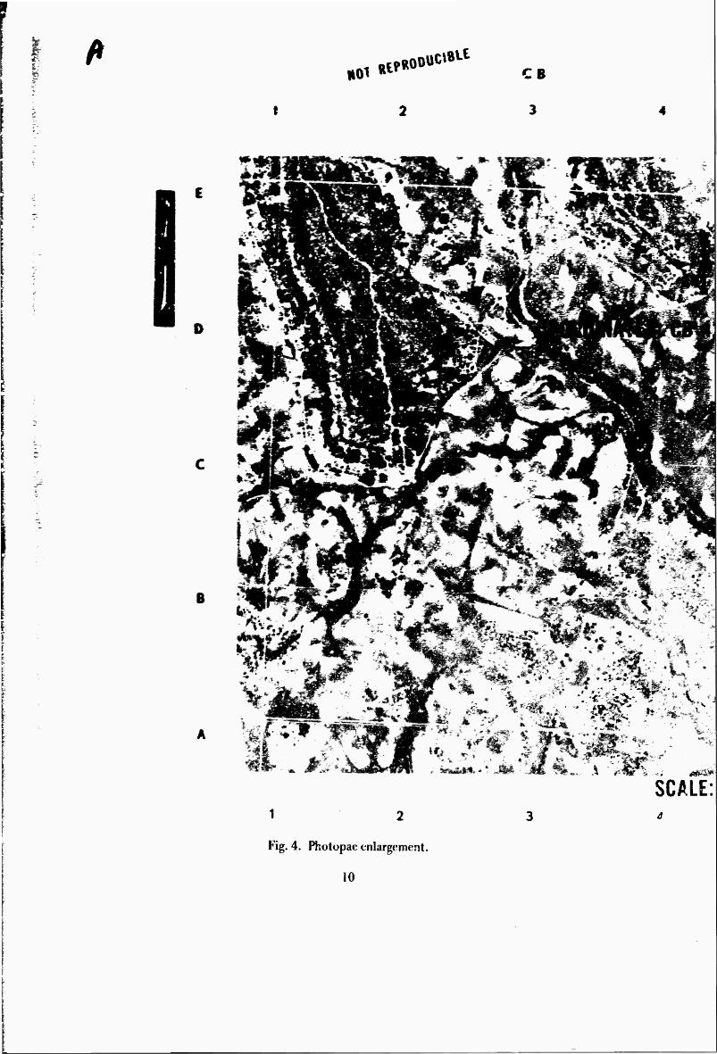
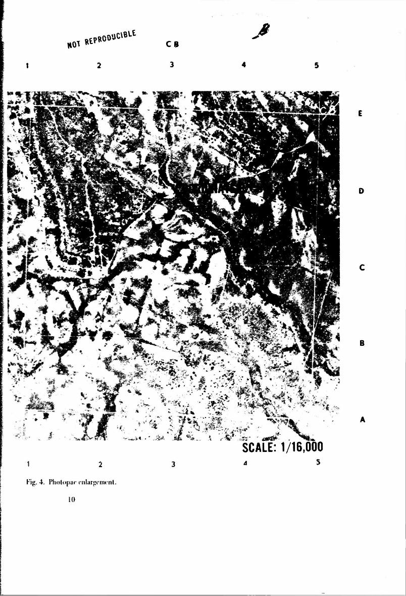
6. Graphic Materials. The graphic materials used in HELBAT !I represented a hasty design of a graphic aid for use in conjunction with the PF. These graphic materials, called Photopacs, were prepared from the same aerial photography (data base) used to make the glass plates for the Balplex projectors. Each Photopac consisted of 21 photo- graphs, one film overlay, and a cover sheet. There was one index photograph of about 1/60,000 scale which included all the forward observer positions and the target area. The index photograph was covered by a 4-centimeter grid which had its lines running approximately North-South and East-West. Each grid square had a letter designation on the film overlay (Fig. 3). For each of the labeled grid squares o* the index photo- graph, there was an enlargement of about 1/16,000 scale. These enlargements also had a 4-centimeter grid on them with the North-South lines designated by a number (1, 2, 3 . . ., etc.) and the East-West lines designated by a letter (A, B, C ..., etc.) (Fig. 4). The 4-centimeter grid size was chosen because it is the standard size grid for a 1/25,000 scale map. and this made it possible to use standard map coordinate scales for determin- ing coordinates. One sample point is indicated on Figs. 3 and 4. The resulting product was a small book of photographs. The photographs were on a substance called Chrona- paque-a lough, film-based type of printing paper. Each page was 10 by 10 inches, and the book was approximately ^-inch thick Chronapaque was used rather than regular photographic printing paper because of the extremes of weather and the hard usage the photographs would probably be exposed lo.
7. Training. Two different types of training were required for the HELBAT II operations. The firsi type of training was that which was provided for the men who wrc to actually operate the PF during HELBAT II, and the other type was given to the Fthv/ard Observers who were to provide input data to the PF through the use of the Photopac.
a. PF Operators. The men who were to operate the PF during the lest were lo sperm about 6,/2 days actually working with the equipment at Fort Belvoir before
8
aNe
ft
Fig. 3. Photopac index photograph.
*w:^ -%>&&.
i%'.
'»■acr 1
SCALE: 1 60,000
Kit:, i. Iliotopar iiid#'\ pliuto^raph.
I: 'P. «01
RipR00 uc«»»-t CB
B
SCALE: 1 2
Fig. 4. Photopac enlargement.
10
HO^ RtPROO'. UCtBLt
C8 ß
i\ ?:
^ .- &* . #■
1 2
Fig. 4. Photopar rnlargfim'nl.
10
SCALE: 1/16,000 4 3
D
B
it was shipped to Fort Hood. Tour enlisted men from the 30th Enginwr Haitaiion (Base Topo) arrived at ETL on 11 January 1971 to begpn training on the PP. All «f these men had previous military training and experienee with stereopiottin|: te(*hiiKpK^ and equipment. Their initial training consisted of a grneral introduetio» tu ihi* PK «(»n- oept, HELBAT11, and related background information. Their work on the «ntiiat equipment was also preceded by some training »n radio procedures sad famiiiari^tton with the Photopac.
The training on the PF equipment covered all phases of the oiieration including setting up and orientation of the stereomodeK entering computer control values for the model, and reading in computer program tapes. Several day- Here spent practicing the image matching technique and becoming generally familiar with the area covered by the stereomodd. The procedure used during (his period was similar to that which was expected to be used during the actual test. One man would choose any point in one of the enlargements in the Photopac and scale off its coordinates. These coordi- nates were then told to the ether man who replotted the point« in their own Photopaes. After plotting the points on their photos, the men went to the stereomodel and d^-h-r- mined the coordinates of the pjnt which they had plotted. These ITM coordinates and the visual location of the points were then compared to the location as determined by the person who originally picked the point.
At the end of the training period, two of the four men who had been trained were selected to actually participate in HELBAT II at Fort Hood.
b. Forward Observer Training. The FO's received different amounts «f training depending on whether they were •'Conventional" FO's. "Laser" FO's or ''Super Laser" FO's. The "Conventional" FO's were those who had only a 1/50.000 scale topo- graphic line map and an M-2 Compas* to use for determining locations. The ^I^aser** FO's used a Laser Hangefinder along with their map and compass. The "Super Laser" FO's had an ARK-1 Gyrocompass as well as a Laser Rangefindcr. map. and compass. The "Conventional" FO's were inadvertently excluded from about 3/4 of the training given to the other FO's because they did not need to receive any special training from the HEL personnel before the test.
The Laser and Super Laser FO's received a total of about 1 hour of train- ing. This was split into three sessions. The first session, which lasted about !44iour. consisted of an introduction to the PF concept, the equipment, and the associated graph- ic aids. The Super and l*aser FO's were shown the PF equipment, and the procedure for its use was explained to them. They were told how to extract coordinates from the Photopacs and how to use the stereograms which they had been given. Photopacs. co- ordinate scales, grease pencils, stereograms, and glasses were issued to the Super and Laser FO's during this period.
11
---
Tht• st"l'ond training pniod, w hit'h lasll'd about IS rninules, also indudt·d onlv tlw ~lljH'r and La:-wr FO\. It t·onsisll'd, primarily, of a dwt'k to st·t~ if thl'y 1111dn,;tood how to :-walt· t·oordinalt:s from tltt' photographs in the Photopac.
Tlw third t rai11ing Sl':-;:-;ion la:-;Lt•d about IS rnilltltt•s and indrult~d all of tlw F< )",.;front t•adt Battalion. Ont' of thl'sc st•s:-;ions was t'ondudt'd for c'twh Ballalion's
FO\ _jt1st l1don· lht'_v ntovt·d out to thl'ir ohsnvatio11 posts. This period constituted thl' only fr;titting rt'tTiH·d by tl~t• Convt•ntional FO's, and it was timing this st•ssion that they ,;aw tilt' l'ltotopat· and tht' stneogrant for the first time. This was primarily a gt~llt'ral rt~' WI\ of tlw prtlt'l'dtlrt' for ,;caling t:oordinall's from tlu~ Photopacs.
H. 0 pt•ra tiona! Procedures. Tlw P F was t'lll ployt'd print:i pally for determining ol'"''n;t!ion po,;ts and targt·t coonlinatt•s: but tlw dt'lnmination of BattPry Ct·ntns tkotl!..':h tlw tlst• of Polaroid photographs taken from a helicopter and tltt~ imagl'-matdt
ttTint!qlw and st'lling •rp dwck-points for liSI' with th<~ Improved Position Lol'ator (lPL) I\ t'IT al,;o t•:--arnirwd.
a. Observation Po.sl and Target Location. The op_t~rational procedure which I\ a,; t'lltpl(l: f'd to tlt-tnrnillt' Forward Oh,;t'I'Vt'r/Obst'rvation Post Locations or targd lot:ati'"'"' I\ a,; ''""''lltialh' tlw san1<·. The prol'cdurc was as follows:
(I) Forward oh;;t'l'\'iT plot It'd his position or targl'l position 011 what ht• IJI'Iint·d \\a,; tlw t'OITI'cl t'lllargt'lll<'lll i11 his Photopac.
(:2) l.'orward Obsnvn tlw11 scakd off the photo coordinates of tlw point plot lt·d a:' his po~ition or targd po;;ition ttsin~ normal proc(•tlttrc for <kkr
rnining rnap ('oordinat('s by rrwa:-;uring I. 1. tltt~ l•:a;;tillg and lltt•n lht' Northing.
(:1) lll·:LIL\T l'orttrolln then rccord('d lhe photo coordinat(~S 011 tiH' d;tLt t·ard !'or ll1at mi,.:,;ion.
(-!.) [lata cards wt·n· t:ollt~t:l<·d w!t!'n co11trolkrs came in from llw fi('ld ;111d tlw plto[o dala was cupit•d ..
\.1) !'oint;; wcn~ IIH·n plot lt·d in Plwtopacs at tlw PF.
((l) l 'sing an inwg(~ rnatdring tct:hlli()IH~, point in photograph image was f()IIIHI in ,.:ttT('Otllodd.
(7) Cornpult·r tltt'tl gav!' printout of LJT:\1 coordinates and devation of p~>int.
12 BEST AVAILABLE COPY
r
This procedurc was rqH atnl for t•aeh data samplt~ which was rt·t·or·tl!•d.
b. Loe<ttion of Battery Ct~nters. Another pr01:edun• whi«'h was trit·d was to tt,.:c! lw inlagt··rnalch !t'l:hniq!H' in conjunt:lion with Polaroid photographs lakt·n from a !wlit·t)ptn to lol'a!c b:tttl'ry centers. Tlw procedure was as follows:
(I) A Polaroid pidnn~ was taken of a Firin~ Bat!t'ry from a lwlil'optn
:1! an a!titudt' of approximately SOO fed and an :mglt~ of .j.;) to 60 dq.~rt·t·s from the vntical.
(2) The prints wert~ returned to the PF.
(;~) Tht· approximate Batlny location was found in the stercomodt·l and the lor.·ation of the Battery Center was est irnalt'd.
(:1.) ,;, , .,;;;pukr printout of the UTi\1 coordinalt's amltlw dt·vation of tlw t•slimatcd Ba!lnv C1~nkr were obtained.
e. IPL Checkpoints. Several dwd~points WITt' t•stablislwd alonl! an lrn· proved Position Locator (IPL) route as rdt~r·erHTs in all atktnpt tu t•valuall' tlw df1..-( of varying types vf lnrain on the necuracy of the IPL. Thcsl' <'hc<"kpoints could lw t'X· JWc!<'d to lw alTllralP within 20 rneters.
Ill. DISCU:-;SION
9. General. Tlw principallwnefiL f'('Sillting from utilization of llw PF in IIELBAT II ('amc in the form of I'XJHNtfl' of the sysl<·m ami cont'l'(ll to a laq!;t' llttllllwr of Fil'ld ·\rti!lt·r: pnsonrwl. In general. llw \'isilors to tlw PF dttrirrg 111-:LBAT II Wl'!'l' \l'ry I'll·
ll111sia~t i(' a!HHtl its pot('ntial applications. This intt'n~st wa:-; cxpn·~st•d by HH'll at all li'\TL~ of t•ornm:md. ;~nd lhl' prirnary point of dii'Wtlssion was nol wlwtlwr a r·apabilily :'licit :tc: I h:t! dt·rnonslrall'd II\' tll1· PF should IH~ mad!' a\ailabk lo tlw Fit•ld t\rtill<'n. Juri . . rather, tlw urganizalionallev1~l at which this capability c:ltould lw ckplo;.Ttl.
As a lt·c:t for tlw PF I'IHH:l'pl and t'quipmcnt, IIELBAT II was of somPwhat lt·ss
vahw lwt':lltSI' !ll!' PF was eonsidncd for II ELBAT II onlv a short tinw lwfon· tlw !t•sl. . ... ~
BtTaus!' of this, the PF had to he act~onnnodatcd in Hll t·stabl·islwd Tc:-;1 Plan. Con."t'· quclltly. the PF was not an integral pari of IH:LIL\T II bur was givt'll a rolt· for subjt•t·livc
n:duatirm rat!H"r th:w a ri;,;orous operational !t•sl. Dala for the I'F wa~ ~atlwn·d primarily
una noninl<~rl'l'rt•ru:c basit'. which nwarrt that at soml' lirnt•s the FO's Wl'rt' altlt• to tak1· tlwir tinw and do a l'ardul job and at ullll'r tim<'s thl'y had fo rush so that tlwy t·ould ~l:trl planning llwir next mi;;sion. Tlw llt'ar lol:tll:wk of training of i'ionw FO's in tlw
BEST AVAILABLE COPY
lililil;tli.,,, ol ;wri;d pho!o;!raph,.; with tlw point dt·,.;i~rwtion eoordina!t•:-; in t•onjrrndion
'' ith !Ill' pn·"-"llrt' i•• '"'r~, rapidly rrndorrb!cdly corrrpromi:-;t•d pnfortrlalll't'. Orw n•:-;ult 11f tlw !.':t'll<'r;d lad .. of •·rnpha,;i,.; on lht' PF durin~ tlw frainin~ pniod pn•et·din~ tlw tt·,;t ''·'~ IIJ;tl nun\ .. !' tlw Hl'~ "''''llH'd to f,·,·lthattlw PF and their data for it wa:-; tlw lt•a:-;t irnp .. rLIIJ! p;tr! uf t!lt'ir imoht·nwnt in IIELIL\T II.
I 0. llata :\naly:-;i:-;. II El.lt\T II prodrrn·d tlw fir:-;! data wlridr can be rr:-;t•d to ,-,;dli;Jt,· tlw PF', pnlt-11tial applit·atioll:-; within tlw Fidd Artillery. Tlwn· wen• two typt•:-; of 111i~~ion:-; for "hid1 ,.;uffit·it'lll data wnc t'olh-dt·d for nrrnwril'al analysi:-;: (I) wht•n· lilt' H l dt"tnmirwd hi,; own lot·ation:-; ll:<illl! tlw Photopat': and(:!) whPrt' till' FO ddn· rnillt'd t .1r::t'l ltw;!lion,: in tlw ,:anw lllaiiiH'r. .. \lthotr~h thl':o;e l'XI'I'l~l'S did rt'tprire use of llw inla!.':t'·IIJ;Jt•·hin~ 1t'dllli1Jllt' f,y tlw PF opnator:<. tlw primary rt':<trlt was an indit·ation .. r till' ,·;qlabilit: of tlw FO to tr:<e anial photographs (Photopaes) to dt'lt'rmirw location:-; in til,· fidd. 1\,·,·atl"t' tilt' primary t•mpha,:i:-; in tlw:<t' Forward Oh:-;ern·r mis:-;ions was on tlw H ~-~ •·;ql;Ji,ilit: It: ,l,·inrnirw loe;~lion:-; u,:in~ :tnial photo~raphic ima~ny. an at lt'mpl '' ;1,: madt· to dt·lt'rmirw wlwtlwr a11:· of tl~t· · -'tdtmg crrors Wt'rt' t·au:-;Pd hy can~le:-;srwss in "t·;dill!.': and n·t·ording t'oordinatt•,.; or otlwr human nrors ratlwr than an inability to ;ltTtJr;J!t·h pinpoint a ltwalion within thc imagny.
a. .-\nalysi:-; Proet"dure. Tlw ,.;anw gcrrcral proccdure was wwd in tlw cvaltr:1· lion ~~r d;1L1 for both Fl'rward Oh,.;nvcr and lar~d ltwation mi:-;:-;ions. As was pn·viously II It'll! it lilt d. tlw phol<; t'nnrdinatt·~ which the FO\ had recorded in the field wt~n· taken In till' 1'1.-. <IIJd l '1.\1 ,., .. ,rdinalt•,.; wnt· dt'lnmirwd through the imagt'·lllaldt prot~t·s,.; and
!II,· ''"Ill fit! In IT<Jdo11l. Tlw,:t l"T\1 l'oordina!t•,.; of oh,.;nvalion posts and targets were
tllt'n t'll!llp;trt·d 11itii fumllt-ordn ;•: lillt-ry smn·y,; whit·lt had lwt•n rtllt to all ohsnva!ion
il"'l' <IIJd Llr!.':<'l". lilt' ~111'\t'_l tL:ta """ 11:-'t'd a,; tlw lta,.;i,- for all nror anal.'"''"· Tlw varia· 1ion, in l·:;t,:l l!.': <IIIII l"ortltin~ Wt'IT t·onvcrtcd lo radial nrors, and then individual stand;trd dt·li;t!it>ll" wn•· <·;tlntlal:·d usin~ all of lite data for t•aeh of till' two t~·pt•s of missions.
Tl'"·''' daLt "<lllif,:(., wlti•·;t wnt• found to lw greatn than three tirncs tlw standard di'Vialitlll 1\t'l'l' ,.,,l!"idt·n·d to lw o11tlins and wen· n;f'iudcd from the t·alt-ulation of tlw nwan r; 11 i i; rl '·1-r' , .. '11 d !lit· I{ \I:-;.
h. Forward Ohl'erver Lo<::t.lion. The forward ohscrvn location nrors of lht' J.'() '"'';II i1111 rni~.,inll." ;trt· a:' folio\\~:
:-;, 1>. (:\II)
\il·::\\ IL\J)IAL 1-:H.HOH Hl\lS
14 BEST AVAILABLE COPY
The data from foui nissioiis wc*rt* diM'fiuntrii bfcaUüf* thev were proven to contain i-rrurs which resulted from cardetisneiw in M aliu«; ami recording coordinates rather than from an inability to det^rminr the O.P. location on the photograph. In fhree cases, these errors were the product of a combination of carelessness and the con- figiiration of one enlargement in the Pfiolop. *-. Tliree of the data samples, found to be greater than three times the standard deviation, were considered outliers and were not «wed lo calculate the mean radial error and the RMS. These three dr*a samples consti- tuted approximately H'J of the total data. Figure 5 shows the distribution of radial errors from tie Forward Observer location missions.
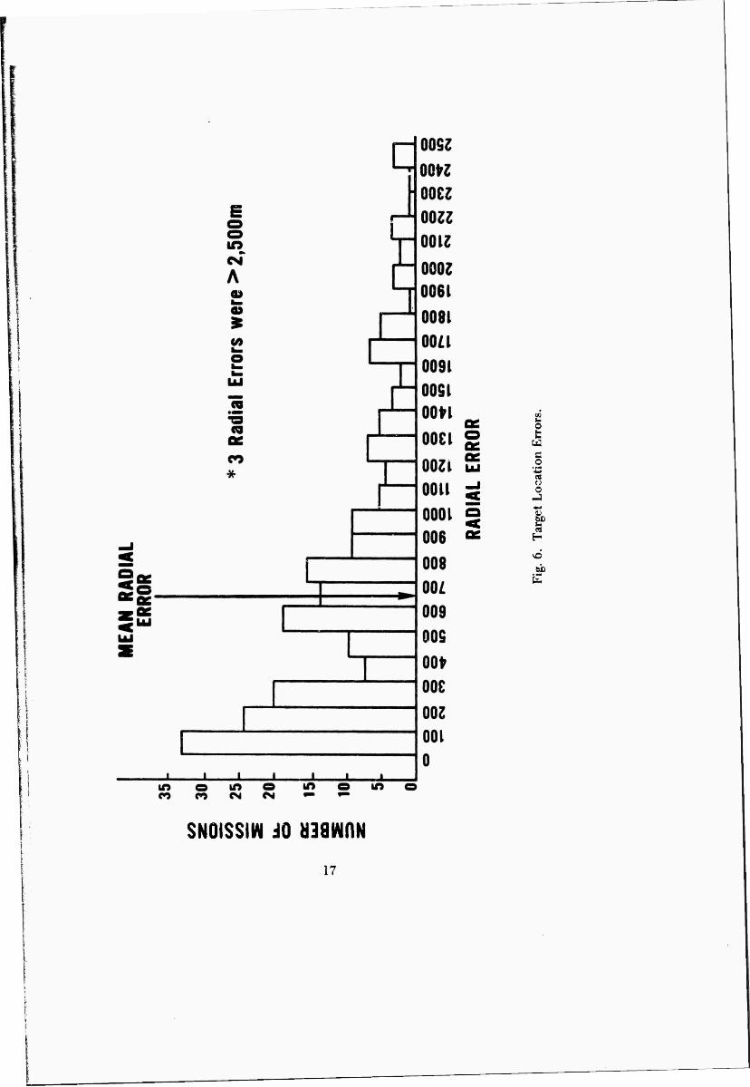
c. Target Location. The results of the target location missions arc as follows:
Number of Missions 210
S. U. (All) 647rn
15 Samples > 3 x .S. I).
MEAN RADIAL ERROR RMS
604ni 786ni
All of the data were assumed to he valid, because it was impossible to determine conclu- ffivciy whether any were compromised purely through improper scaling techniques.
Fifteen data samples, or about 7f/t of the total, were found to exceed 2hree times the standard deviation and were considered outliers. The distribution of the radial errors M shown in Fig. 6.
d. Battery Center Location. Only a small amount of data were collected on the process of determining the coordinates of firing battery centers by using Polaroid snapshots of the batteries taken from helicopters. The only results obtained were ar- rived at while the computer was inoperable; and, even then, only two exercises were performed.
11. Test Results. Utilization of the PF in IIELBAT II yielded what should be consi'1 red indications rather than conclusive results. The basis for this statement is dis- cussed in paragraph 9.
a. Equipment. Considering that the equipment which comprised the PF was commercial, off-the-shelf equipment, il performed quite well during 11KLBA7 II. KTL originally stated that the equipment would require environmental control (65° to 75° F temperature and 'i5 lo 55^ humidity) whon operating, but it was soon discovered that these constraints could not be met at Fort Hood during the test. The temperature in
15
CM CM
A </>
o
is CO
cz
CM
CM
2 os
o u ä a o
UJ t u
o S3 Urn
00 CO in CO CM
SNOISSIW JO «awnN
16
I :
[ ;
: j
w B O
a o
vd
SNOISSIW dO naawfiN
17
the PF Van ranged from about 45° to 93° F, and the humidity varied by about 50%. The Baiplex Stereoplotter and the SIA functioned perfectly at all times, but operating difficulties were experienced with the Traverscan System at both temperature extremes. Humidity variations did not seem to affect the equipment. Dust was also abundant, but it was not possible to determine if it affected the equipment.
The equipment was subjected to several power losses and at least one series of surges as a result of generator operator error. The computer apparently had. a partial memory loss as a result of one generator stoppage, but the program tapes were read-in after eeveral attempts and the system resumed normal operation. The power supplied tu the equipment ranged from about 109 volts to 120 volts. It was discovered that the computer would not function properly at less than 109 to 110 volts.
The PF Van and equipment were moved several times while at Fort Hood. Each move called for partial disassembly (removing the projectors from the frame) and bracing of all equipment which required about 30 minutes to complete. Several hours were required to reset the Stereomodel and resume operation after mov- ing. The time required for setting up the model would have been greatly reduced if the new computer program which would eliminate the need for scaling the Stereomodd had been received.
A serious computer malfunction occurred three days before the test was scheduled to end. A technical representative from Keuffel and Esser (K&E) came to Fort Hood to correct the problem. This malfunction may have resulted from the operating conditions, but this assumption cannot be stated definitely at this time.
The Stereoplotting Equipment functioned perfectly during the entire test. Befor. HELBATII, there was some question about how well the delicate project- ors would stand up to dust, extreme temperature and humidity variations, and move- ment in a military vehicle. The results were very encouraging, and ev^n the constant flow of visitors in and out of the PF Van and the rocking of the Van by the wind which was expected to cause problems in keeping the projectors aligned had negligible effect.
Detailed tests of the accuracy of ground (UTM) coordinates determined by the PF were not possible, although some survey control which could be identified by personnel stationed at Fort Hood was compared to the listed survey coordinates. The coordinates as determined by the PF varied from the survey data by about 6 to 12 m in Easting and Northing.
The experience gained from participation in HELBAT II led to the con- clusion that several equipment modifications would help to improve the overall efficiency and etfectiveness of the PF. Some of the suggested changes are:
18
(1) Ruggedizcd teletype
(2) Continuous visual coordinate readout
(3) Better balance for the tracing table and a larger platen
(4) Heater/air conditioner to stabilize environrnenta' conditions
(5) Method of permanently fastening Bendix Data Grid to Stereo- plotter frame.
b. Graphic Materials. One area in which HE LB AT U was expected to shed some lig'it was the capability of people without any photo interpretation (PI) experience to make effective use of aerial photography in the field. Most of the people who were exposed to the Photopacs during HELBATII had no previous experience with aerial photography. Their degree of success in using the Photopac seemed to depend more on attitude and the desire or lack of desire to perform well than on any other factor. That the Photopacs could be used successfully was first demonstrated by personnel from HEL prior to this start of HELBATII. It was necessary for the HEL people to determine the best routes to all of the OP's to be used during the test, and they soon discovered that the 1/50,000 scale line maps which they first triod to use were of little help. After be- ing given Photopacs, these men, none of whom had previous PI experience, were able to find every OP without difficulty. On the other hand, there were several cases where the FO's made gross positioning errors simply through carelessness. In one instance, the FO held the Photopac upside down while measuring coordinates thus introducing approxi- mately a 650 m error in both Easting and Northing (each grid square on the enlargements was approximately 650 x 650 m). In at least three other cases, FO's correctly identified their positions on the index photograph but then scaled off coordinates for a different ground feature on the enlargement because in their haste they chose a prominent feature which happened to be in the center of the enlargement rather than their actual position which was up in one corner. (See point indicated in Figs. 3 and 4.)
In general, the design of the HELBAT II Photopac was somewhat less than ideal. The primary problem was that the small area covered by an indridual en- largement seemed to confuse some of the users. This was particularly true for target location missions because there were relatively few features in the impact area which an FO could use to help orient the photographs. Also, the loss of resolution which resulted from the 10X enlargement of the original photography to the 1/16,000 scale used for the eriargements caused some difficulty for the inexperienced users. HELBAT II indi- cated that in future experiments it might be wise to test graphics which are printed on a larger size base material to include a larger area and are printed at a slightly smaller scale (say 1/25,000) to improve resolution.
19
c. Operational Procedures. Since HELBAT II provided the first field test of the PF concept, there were no established operational procedures to follow. These procedures were, therefore, established and revised as the test progressed. It became evident that the primary problem with respect to the operational setup in HELBAT 11 stemmed from the absence of direct communication between the FCVs and the PF. This situation made it difficult to evaluate the responsiveness of the PF to incoming data. Those data which were relayed back to the PF by the Div Arty umpires at the OP*s were frequently different than the corresponding information on the HELBAT data cards. Another benefit which direct communciation with the FCTs would have produced became apparent when the photo coordinate data were being processed at the PF. In many cases, the coordinates which an FO had given as being those «. his own position were found to be in error as soon as they were located in the Stereomodel. They were obviously in error because the points were located either in such a low posi- tion that they would not be chosen as observation posts or else they were in such a po- sition that the observer could not possibly see the area of interest which he had been assigned. Had direct contact been established, the FCTs could have been told to check and/or correct their location estimate.
HELBAT II experience provided a basis from which techniques and pro- cedures can be developed for future tests.
d. Potential Applications. Quite a few possible applications for the PF concept have become evident as a result of its development and exposure. Those which became most obvious during HELBAT II include the following:
(1) Forward Observer/Observation Post and Target Location. Use of the PF in conjunction with graphics given to the Forward Observer has shown defi- nite promise, and it is felt that a man with some photo interpretation training or experience could use aerial photograph imagery to even greater advantage. The table shows a comparison of the mean radial errors achieved during HELBAT II by Forward Observers using 1/50,000 scale line maps alone and the Photopac in conjunction with the PF.
Comparison of Mean Radial Errors
Photopac/PF Line Map (1/50,000)
F. 0. Location Target Lontior
67m i 604in
97m 479m
The poor results in the target location missions sing the Photopac are difficult to evaluate. Much of the error probably was caused by the difficulty of working with
20
the small area covered by the enlargements, but other factors were also involved. The first two Battalions tested had a target location RMS of 463 m, but the intro- duction of data from the last two Battalions resulted in a total RMS of 785 m for the four Battalions. Aside from some inclement weather conditions which the final Battalion was exposed to, there is no apparent reason for the extreme degrad- ation of accuracy. More testing, particularly with other types of graphics, is re- quired to determine the value of aerial photographic products in the field.
(2) Battery Center Location. The feasibility of using reconnaissance photography of emplaced firing batteries to ctermine battery centers was demon- strated during HELBATII. The photography used was taken by a Polaroid camera in a helicopter. The photography was difficult to use because of the poor resolu- tion and the oblique nature of the photography necessitated by the small field of view of the camera. Never'Heless, in those instances where it was attempted, loca- tion of the area in the Stereomodel was achieved. With higher quality, wide angle lens cameras and panelled points, this procedure could probably be accomplished very satisfactorily.
(3) Establishing Reference Points. Reference points for use with the Laser Resection techniques or techniques using Lasers and Azimuth Determining Instruments can be established by the PF. Although the PF was not used to estab- lish reference points for use in these procedures during HELBAT IT, the techniques proved to be very accurate for determining FO locations when refereicc points es- tablished by fourth-order ArtiUery Survey methods were used.
(4) IPL Checkpoints. The accuracy and range of the IPL can easily be complemented by the PF. Any point which can be identified in the Stereomodel and on the ground can be used as an initialization or check point for the IPL
(5) Terrain Analyses. The Stereomodel can be used to perform general terrain analyses, route reconnaissance, situation studies, etc., since all information in the aerial photograph imagery is viewed in three dimensions.
(6) Unit Boundaries, No-Fire Lines, etc., can be established and the coordinates of their boundaries determined with the PF.
These are just the principal Field Artillery applications which were dis- cussed during HELBAT II and by no means do they represent all of the potential appli- cations for PF-type equipment.
21
IV. CONCLUSIONS
12. Conclusions. It is concluded that:
a. The experience ol HELBAT I! has reinforced the belief that photogram- metric equipment and techniques can be used in the field to help provide solutions to many Field Artillery survey/positioning problems as well as to provide a source of ter- rain information to be used in making command decisions.
b. By subjective analyses, the capabilities offered by deployment of a Type PF go beyond Field Artillery positional needs and, in fact, have appliation to many Field Army operational needs.
c. Analyses of test results and operating procedures indicate that for future testing, improvements can be made with regard to the data base materials, the PF hard- ware and software components, and Jhe associated graphic materials which should result in enhanced capability and utility.
d. Personnel with no experience in using aciial photographs should at least be given some familiarization in photo interpretation techniques before being expected to make use of them in the field.
22