Embed Size (px)
Citation preview

69th International Astronautical Congress (IAC), Bremen, Germany, 1-5 October 2018.
IAC-18 Page 1 of 16
IAC-18
Special Testing and Test Strategies for Unique Space Hardware Developments
Patric Seefeldt*, Tom Spröwitz, Jan Thimo Grundmann, Eugen Ksenik, Eugen Mikulz, Siebo Reershemius, Kaname Sasaki, Maciej Sznajder
German Aerospace Center (DLR), Institute of Space Systems, Robert-Hooke-Str. 7, 28359 Bremen, Germany * Corresponding Author
Abstract
Hardware developments for new and innovative space applications require extensive testing in order to demonstrate the functionality under the expected environmental conditions. Within several projects the German Aerospace Center (DLR), Institute of Space Systems used its test capabilities for unique tests campaigns that went beyond standard qualification testing.
Several developments in recent years focused on deployable components and corresponding mechanisms. Examples are Solar Sail developments in DLR’s Gossamer-1 project, Drag Sail developments in ESA funded projects Deployable Membrane and ADEO, the test of an articulated boom in the ESA project ABDS (Articulated Booms –Large Ultrastable Deployable Structures), separation and deployment tests of the HP3 instrument used on NASA/JPL Mars mission Insight, the MASCOT (Mobile Asteroid Surface Scout) on JAXA’s Hayabusa2 spacecraft, and most recently such research and development is continued in DLR’s Gossamer Solar Array (GoSolAr) project.
Especially in the development phase but also for life-cycle testing non-standard tests are required for hardware verification in addition to standard qualification tests (vibration, shock and thermal-vacuum). These tests included venting of stowed membranes, deployment under different thermal-vacuum conditions, shaker tests under cryogenic conditions and radiation tests with electromagnetic radiation as well as protons and electrons. Furthermore, a deployment test rig with the possibility of deployment force measurement was built in a clean room ISO 8 environment. In addition, the combination of all test-facilities allows life-cycle tests according to a test-as-you-fly approach. High-fidelity characterization tests for flight operations planning of critical mission phases were performed at the fully integrated system-level for small spacecraft, including extensive mission environment simulators and multiple-topic instrumentation within one test campaign. Such integrated testing becomes more important as small spacecraft become more and more organically integrated.
For the above mentioned projects and missions different test approaches are described. Test setups, deployment test rigs and other Mechanical and Electrical Ground Support Equipment are shown and the tests as they were carried out are described.
As a result of these test campaigns new technologies were brought to Technology Readiness Level 4 and 5, some are approaching a first flight demonstration and others already proved and still prove themselves in flight, even in interplanetary space. Furthermore, the established know-how and test facilities are being used more and more frequently for unique technology developments.
Keywords: Qualification, Testing, Deployment, Gossamer-1, GoSolAr, ADEO, MASCOT, Insight Acronyms/Abbreviations
German Aerospace Center (DLR) Gossamer Solar Array (GoSolAr) Mobile Asteroid Surface Scout (MASCOT) Articulated Booms - Large Ultrastable Deployable
Structures (ABDS) Euglena Combined Regenerative Organic Food
Production in Space (EU:CROPIS) Closed Life Support System (CLSS) Atomic Oxygen (AO) Ultra Violet (UV) Vacuum Ultra Violet (VUV) Engineering Qualification Model (EQM) Flight Model (FM) Flight Spare (FS)
Structural Thermal Model (STM) Proto Flight Model (PFM) Space Craft (S/C) Hold Down and Release Mechanisms (HDRM) Preload Release Mechanism (PRM) Thermal Vacuum (TVAC) Instrument Deployment System (IDS) Complex Irradiation Facility (CIF) Single layer insulation (SLI) Equivalent Sun Hours (ESH)
INTRODUCTION
At DLR’s Institute of Space Systems [1] several projects were carried out in which hardware for space applications was developed. Some of these projects
69th International Astronautical Congress (IAC), Bremen, Germany, 1-5 October 2018.
IAC-18 Page 2 of 16
were carried out together with other agencies such as JAXA and NASA, others were carried out in a partnership with German industry and some were internally funded R&D projects. One aspect in these projects was development and verification testing. For such activities the project teams can make use of different in-house test facilities. Being a research institute the developments are often not comparable to standard space hardware developments. The missions and project always have an experimental and research character which often requires special tests to ensure certain functionalities under the expected environment. After a brief description of the test capabilities in Section 2, different test campaigns are addressed with respect to special testing activities in Section 3. As a result of these activities several hardware developments reached a TRL of 4 and 5 after environmental testing and some developments now are already proving there functionality in space. With Section 4 a short conclusion and an outlook to future activities is given.
2. IN-HOUSE TEST FACILITIES For the development and qualification the above
mentioned missions in-house laboratories were used [2]. This includes facilities for mechanical-dynamical testing, thermal-vacuum testing, radiation testing and deployment testing. The following subsections give a brief description of the available laboratories.
2.1 Mechanical-Dynamical Test Laboratory
The mechanical-dynamical test laboratory is typically used to verify the mechanical design of space components or systems to withstand high dynamical loads especially during launch. In the laboratory dynamical loads (sinusoidal, random, half-sine shocks) can be tested using electromagnetic vibration shakers. There are shakers of size 37 kN and 89 kN (see Fig. 1 left) available in the laboratory
High transient loads (pyroshock events) can be tested in the pyroshock test stand (see Fig. 1 right) consisting of an Aluminium ringing plate for load transmission and a pyrotechnical nail gun for shock initiation.
Fig. 1: Left: 89 kN Vibration Shaker with mounted Eu:CROPIS Structural Model; Right: Pyroshock test stand during a shock initiation
In combination with the infrastructure for thermal-vacuum tests mechanical-dynamical tests can be performed under different temperature boundary conditions like temperatures that can be reached with liquid nitrogen.
2.2 Thermal and Thermal-Vacuum Laboratories
The thermal-vacuum laboratory consists of several vacuum chambers of different size. To mention are the Space Simulation Chamber and the Sun Simulation Chamber.
The Space Simulation Chamber as shown in Fig. 2 is a diameter 2.1 m, length 4 m recipient with a shroud and different cold plates. The shroud is divided into four segments where individual temperatures can be set between -180°C and +120°C. Cold plate temperatures can be varied using a Huber thermostat in different ranges depending on the cooling fluid selection. The chamber furthermore features a Sun simulator obtaining a hexagonal irradiation area of 1 m outscribed diameter with maximum one solar constant.
Besides standard thermal-vacuum testing the facility is increasingly used for venting tests and deployment tests in thermal-vacuum environment for a wide range of applications as will be presented in later paragraphs.
Fig. 2: Closed recipient of the Space Simulation
Chamber The Sun Simulation Chamber is a diameter 0.45 m
and length 0.8 m recipient consisting of a shroud that can be cooled with liquid nitrogen leading to -180°C shroud temperature and different cold plates together with Huber thermostats are used. The facility also features a Sun simulator achieving one solar constant on a circular area of diameter 100 mm.
Both facilities provide numerous different costumer feedthroughs to ensure functional testing of the different test items.
2.3 Complex Irradiation Facility
The Complex Irradiation Facility (CIF) as shown in Fig. 3 is used to investigate material surface degradation due to solar irradiation [2]. Possible use cases are the changes in reflectivity of metallized surfaces on membranes for Solar Sailing caused by the hydrogen blistering effect [3,4] or the changing emissivity and

69th International Astronautical Congress (IAC), Bremen, Germany, 1-5 October 2018.
IAC-18 Page 3 of 16
absorptivity for spacecraft thermal design. Test samples can be irradiated with VUV, UV, visible light and IR together with electrons and protons at varying temperature levels. The electromagnetic sources are an Argon lamp for VUV, a Deuterium lamp for UV as well as a set of Xenon lamps for visible light and IR.
Determination of the surface degradation is performed ex-situ by measuring the hemispherical emissivity and the solar absorptivity of the test items using a Bruker Vertex 80v spectrometer.
2.4 Deployment Test Rig
The test rig, as shown in Fig. 4, has been developed to test the packaging and deployment of large membrane structures. Typical use cases are the deployment of large areas for solar sailing (Gossamer-1), for drag sails (ADEO-1, ESA GSTP 4000112253/14/NL/SW) or for solar arrays (GoSolAr).
Fig. 3: Complex Irradiation Facility with the
different irradiation sources The facility consists of up to four 5 m long linear
drives which can be arranged in a cross-like configuration. They are used either to represent or to support deploying booms which are typically not designed to support themselves under Earth gravity environment. The linear drives are equipped with force gauges having a Bluetooth link to a central data acquisition system. This allows for a monitoring and recording of deployment forces which are mandatory input for mechanisms, booms and membranes design tasks.
Fig. 4: Principle representation of the deployment
test, here an arrangement for the deployment of a half Gossamer-1 Sail with two linear drive units and one boom. Three-axis force measurement is possible on each drive unit.
3. TEST CAMPAIGNS
This section provides an overview of the tests carried out for various projects. The test strategy and particularities are highlighted and the tests itself and their results are described. 3.1 Gossamer-1 and GoSolAr
In the last several years, the further development of scalable deployment technology for gossamer spacecraft systems, suitable for autonomous and controlled deployment was pursued at the German Aerospace Center (DLR) in the Gossamer-1 project and it is now continued in the Gossamer Solar Array (GoSolAr) project. An overview of the Gossamer-1 technology and the mission behind it is presented in [6]. The aim of the project was to develop a deployment system for space applications with a focus on solar sailing and secondary use cases as a flexible photovoltaic array and drag sail. The development was carried out for a 5 m x 5 m technology demonstrator that should in principal allow for up-scaling to 50 m x 50 m. The sail is based on a crossed boom configuration with four triangular sail segments. The deployment technology was subject to an environmental test campaign and reached a TRL of 5.
According to the design presented in [6, 7] an engineering qualification model (EQM) of one deployment unit was built that could be subjected to environmental tests. The EQM included all mechanisms, electronics, two sail segments and one boom (half the sail). Due to funding reasons it did not include a battery and operational photovoltaic arrays on the deployment unit walls. Instead mass dummies for these components were used and the power supply came through the EGSE plug on the backside of the deployment unit.
According to a test-as-you-fly strategy the following tests were carried out in that specific order:
69th International Astronautical Congress (IAC), Bremen, Germany, 1-5 October 2018.
IAC-18 Page 4 of 16
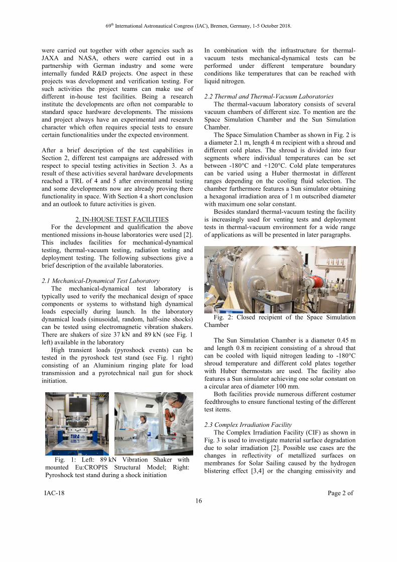
Mechanical Vibration Testing Venting Thermal Cycling Ambient Deployment
The EQM was mounted on a test adapter using the hold down and release mechanisms as presented in [6]. The adjacent sail spools that would be mounted on the other deployment units were mounted on this test adapter in the representative way. The EQM mounted on the test adapter just before testing is shown in Fig. 5. The testing is described in [8]. In the context of special testing it the venting test and the ambient deployment as well as material radiation tests are presented in the next paragraphs.
3.1.1 Venting Test The venting test is made by interconnecting a small
venting chamber (0.7 m3) to a big vacuum chamber (17 m3) with a valve (see Fig. 6). The Gossamer-1 project had to deal with uncertainties regarding possible launch vehicles, included modified military missiles. The pressure decrease chosen for the venting test as shown in Fig. 7 was therefore much stronger then what would be expected for conventional launch vehicles like the VEGA or Ariane 5 launcher (see launcher manuals).
Fig. 5: Gossamer-1 EQM deployment unit.
Fig. 6: Gossamer-1 EQM venting test setup, small
vacuum chamber is vented into the already evacuated big space simulation chamber.
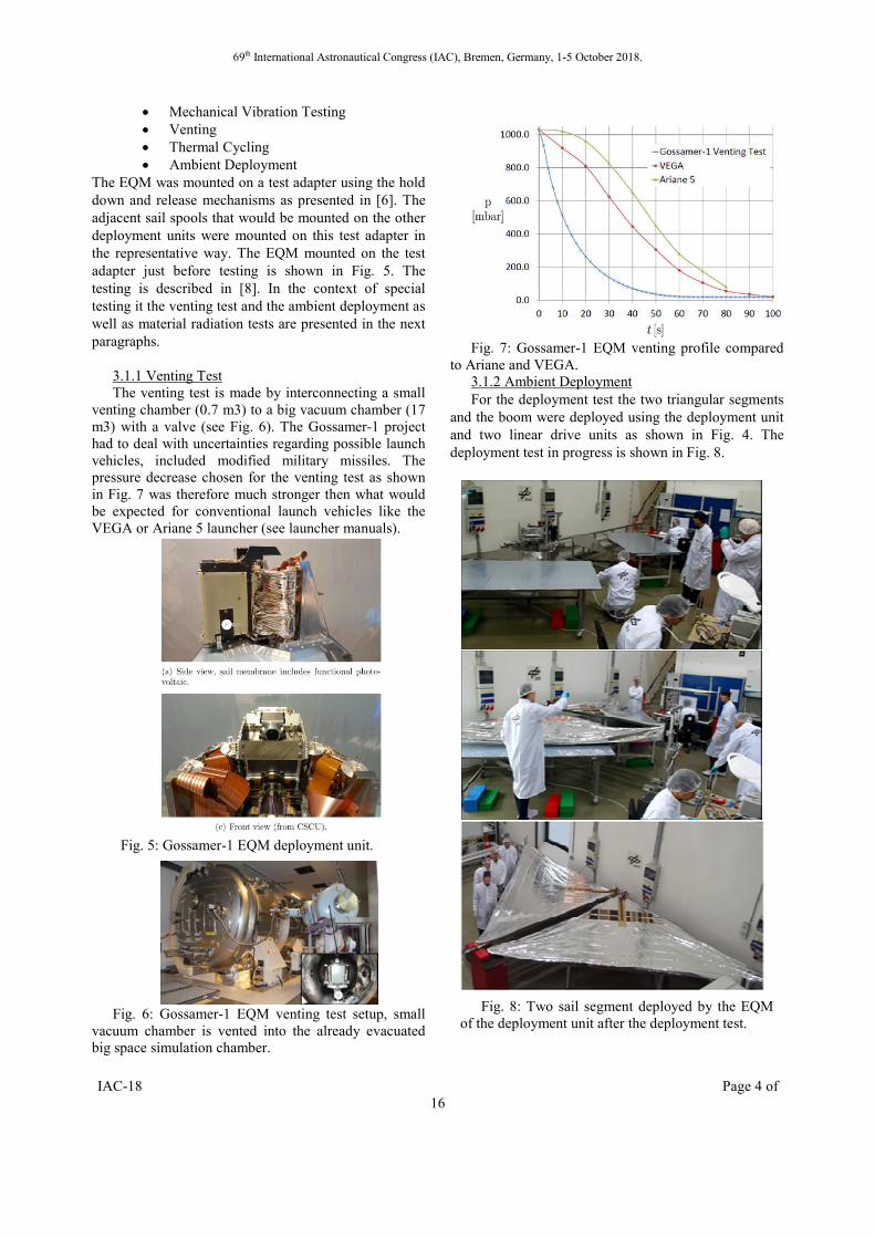
Fig. 7: Gossamer-1 EQM venting profile compared
to Ariane and VEGA. 3.1.2 Ambient Deployment For the deployment test the two triangular segments
and the boom were deployed using the deployment unit and two linear drive units as shown in Fig. 4. The deployment test in progress is shown in Fig. 8.
Fig. 8: Two sail segment deployed by the EQM of the deployment unit after the deployment test.
69th International Astronautical Congress (IAC), Bremen, Germany, 1-5 October 2018.
IAC-18 Page 5 of 16
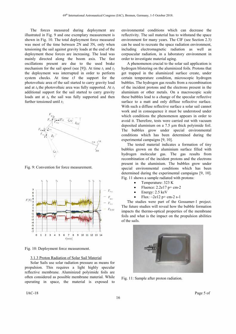
The forces measured during deployment are illustrated in Fig. 9 and one exemplary measurement is shown in Fig. 10. The total deployment force measured was most of the time between 2N and 3N, only when tensioning the sail against gravity loads at the end of the deployment these forces are increasing. The load was mainly directed along the boom axis. The fast oscillations present are due to the used brake mechanism for the sail spool (see [9]). At time t1 and t2 the deployment was interrupted in order to perform system checks. At time t3 the support for the photovoltaic area of the sail started to carry gravity load and at t4 the photovoltaic area was fully supported. At t5
additional support for the sail started to carry gravity loads ant at t6 the sail was fully supported and then further tensioned until t7.
Fig. 9: Convention for force measurement.
Fig. 10: Deployment force measurement.
3.1.3 Proton Radiation of Solar Sail Material Solar Sails use solar radiation pressure as means for
propulsion. This requires a light highly specular reflective membrane. Aluminized polyimide foils are often considered as possible membrane material. While operating in space, the material is exposed to
environmental conditions which can decrease the reflectivity. The sail material has to withstand the space environment for many years. The CIF (see Section 2.3) can be used to recreate the space radiation environment, including electromagnetic radiation as well as corpuscular radiation, in a laboratory environment in order to investigate material aging.
A phenomenon crucial to the solar sail application is hydrogen blistering on the aluminized foils. Protons that get trapped in the aluminized surface create, under certain temperature condition, microscopic hydrogen bubbles. The hydrogen gas results from a recombination of the incident protons and the electrons present in the aluminium or other metals. On a macroscopic scale these bubbles lead to a change of the specular reflective surface to a matt and only diffuse reflective surface. With such a diffuse reflective surface a solar sail cannot work and in consequence it must be understood under which conditions the phenomenon appears in order to avoid it. Therefore, tests were carried out with vacuum deposited aluminium on a 7.5 µm thick polyimide foil. The bubbles grow under special environmental conditions which has been determined during the experimental campaigns [9, 10].
The tested material indicates a formation of tiny bubbles grown on the aluminium surface filled with hydrogen molecular gas. The gas results from recombination of the incident protons and the electrons present in the aluminium. The bubbles grow under special environmental conditions which has been determined during the experimental campaigns [9, 10]. Fig. 11 shows a sample radiated with protons:
Temperature: 323 K Fluence: 2.2e17 p+ cm-2 Energy: 2.5 keV Flux: ~2e12 p+ cm-2 s-1
The studies were part of the Gossamer-1 project. The future studies will reveal how the bubble formation impacts the thermo-optical properties of the membrane foils and what is the impact on the propulsion abilities of the sails.
Fig. 11: Sample after proton radiation.

69th International Astronautical Congress (IAC), Bremen, Germany, 1-5 October 2018.
IAC-18 Page 6 of 16
3.2 Deployable Membrane Within the ESA project Deployable Membrane
(ESA 4000112241/14/NL/SW) the membrane material has been exposed to both the corpuscular (neutral Atomic Oxygen (AO)) and electromagnetic radiation. The membrane material was an Upilex SN 12µm polyimide foil produced by the company UBE and covered one side with the 500 nm vacuum deposited aluminium layer.
Few of the samples had artificially made “defects” representing materials defects caused by handling or deploying the membrane in the Low Earth Orbit environment.
First of the defect is a folding line. It appears on the surface material when a membrane is stowed and packed into the deployment unit, see Fig. 12. The upper and the lower line have a positive and a negative curvature, respectively. Along both, one can indicate tiny yellow dots which are in fact polyimide foil substrate. Both of the lines were done by use of a procedure where a weight of specified mass was laying on a bent material for a given period of time. Such simple procedure reviled an important fact of the aluminium layer. It cracks while being bent and pressed. The uncoated polyimide material is then unprotected against environmental factors which can ultimately cause tearing of the material.
Fig. 12: Two folding lines artificially made on a test
material.
Second type of the defect is a sample area stricken by a debris object under laboratory conditions, see Fig. 13. Additionally, two folding lines have been made. Here, one can clearly see areas where the polyimide substrate becomes uncoated and can be easily degraded by the radiation.
Fig. 13: Sample area exposed to space debris object (middle) as well as two artificially made folding lines, with negative (left) and positive (right) curvature.
The corpuscular radiation test was performed at the
ESA/ESTEC laboratory. The radiation consists of neutral Atomic Oxygen (AO). The energy of the atoms was approx. 5 eV in order to simulate the environmental conditions of the material at the Low Earth Orbit. The flux and the irradiation time ware chosen in order to simulate 20 years of the mission time. That time period is an equivalent of 1021 AO cm-2.
Surface morphology expertise made by an electron microscope clearly show that the aluminium layer withstand the exposure to the AO bombardment.
The next part of the test was to expose the specimens to the electromagnetic radiation for over 7400 Equivalent Sun Hours (ESH) at the Complex Irradiation Facility in Bremen, Germany. That number corresponds to approx. 3 years of material exposure to the light conditions at the Low Earth Orbit environment [11]. The test was intended to irradiate the samples in the most broad wavelength range possible. Therefore, three light sources of the facility have been used: the so-called VUV-source [12], which works in the range of 40 nm to 410 nm, the Deuterium-lamp which generates light within the range of 112 to 410 nm and a Xenon-lamp which works in the range of 200 nm to 2150 nm. The combined radiation of the three light sources illuminates the specimens in a wide wavelength range from 40 nm to 2150 nm. Such test exceeds standard electromagnetic irradiation tests, since they are usually performed by use of Deuterium lamps with a combination of Xenon lamps. Here, by use of the VUV-source, the test material has been exposed to radiation with much higher energies of the photons than dose generated by the standard Deuterium lamps. Such approach provides a unique possibility to examine material response to VUV light.
The electromagnetic radiation test results clearly show that the aluminium does not degrade by the radiation even when the incident light has a wavelength range lower that 100 nm. However, the folding lines degrade in places where the polyimide substrate was uncoated resulting with material structure break. Places stricken by the debris degrade as well, the edge of the hole uncoated by the aluminium become dark brown and some of the cracks present along the radius of the hole become longer. Such results reveal a need of heaving crack propagation stoppers which may prevent ultimately the tear down of the membrane structure. 3.3 ADEO
Together with the HPS GmbH and the HTS GmbH, DLR’s Gossamer-1 technology was adapted for a drag sail application with the ESA project ADEO (GSTP 4000112253/14/NL/SW). A passively stabilized drag sail with a drag area of 5m x 5m was built in order to deorbit a roughly 1tonne satellite from a 700km orbit.
69th International Astronautical Congress (IAC), Bremen, Germany, 1-5 October 2018.
IAC-18 Page 7 of 16
Within the follow-on project ADEO 2 that started in August 2018 a Proto-Flight Modell (PFM) will be built. The sail can be used to de-orbit medium sized satellites of several 100kg in a Low Earth Orbits.
The sail design is described in [13]. It is based on a crossed boom configuration comparable to the Gossamer-1 design but the deployment is driven from a central deployment unit. Besides standard qualification testing all mechanisms needed to be verified in the thermal hot-case and cold-case. On the one hand this required firing of the Hold Down and Release Mechanisms (HDRM) and on the other hand the deployment needed to be demonstrated under thermal-vacuum conditions. These tests were carried out in the SSC (see Section 2.2). The test flow was as follows:
Hot case firing of HDRM Reset of System Cold case firing of HDRM Cold case partial deployment Hot case continuation of deployment Mount partially deployed sail on ambient
deployment test rig Complete deployment under ambient
conditions The HDRM is based on a pin puller designed and manufactured by the HTS GmbH. During the hot case firing of the HDRM the pin puller was at 40°C
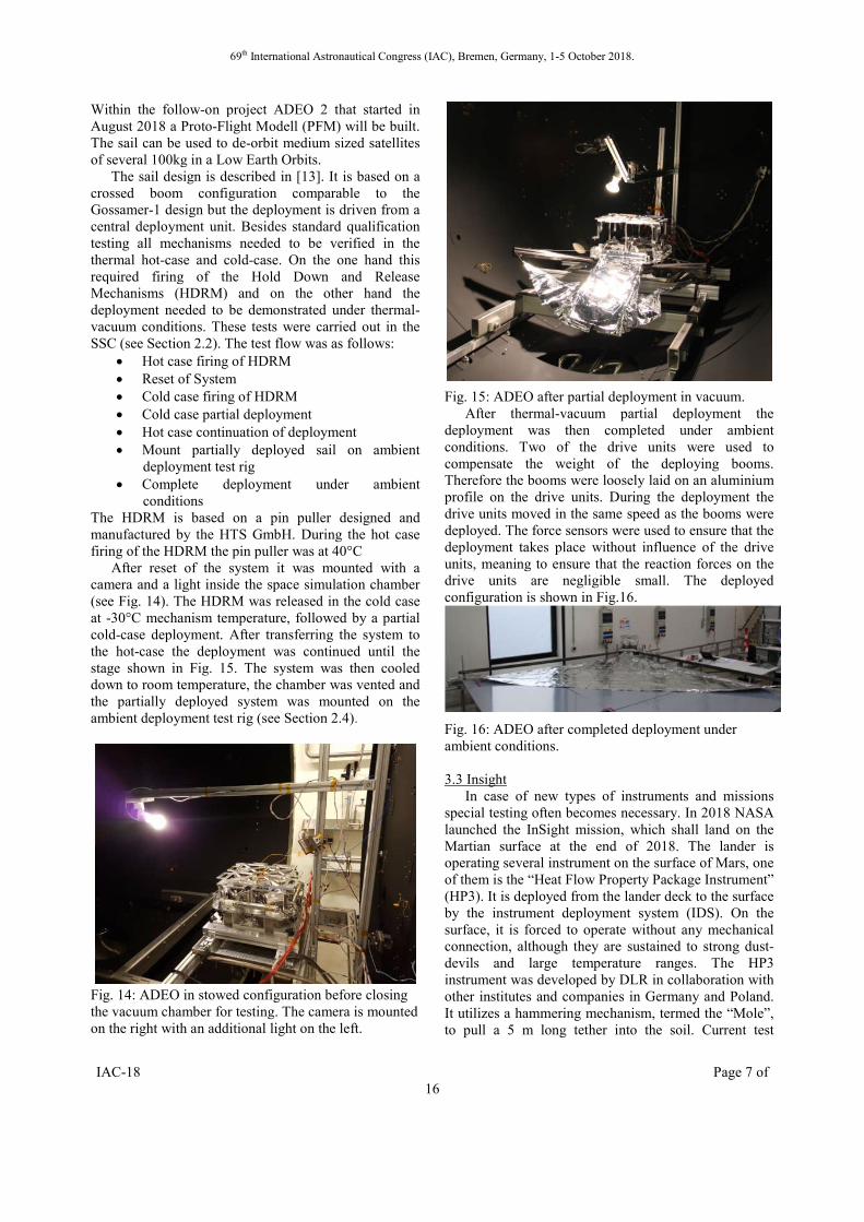
After reset of the system it was mounted with a camera and a light inside the space simulation chamber (see Fig. 14). The HDRM was released in the cold case at -30°C mechanism temperature, followed by a partial cold-case deployment. After transferring the system to the hot-case the deployment was continued until the stage shown in Fig. 15. The system was then cooled down to room temperature, the chamber was vented and the partially deployed system was mounted on the ambient deployment test rig (see Section 2.4).
Fig. 14: ADEO in stowed configuration before closing the vacuum chamber for testing. The camera is mounted on the right with an additional light on the left.
Fig. 15: ADEO after partial deployment in vacuum. After thermal-vacuum partial deployment the
deployment was then completed under ambient conditions. Two of the drive units were used to compensate the weight of the deploying booms. Therefore the booms were loosely laid on an aluminium profile on the drive units. During the deployment the drive units moved in the same speed as the booms were deployed. The force sensors were used to ensure that the deployment takes place without influence of the drive units, meaning to ensure that the reaction forces on the drive units are negligible small. The deployed configuration is shown in Fig.16.
Fig. 16: ADEO after completed deployment under ambient conditions. 3.3 Insight
In case of new types of instruments and missions special testing often becomes necessary. In 2018 NASA launched the InSight mission, which shall land on the Martian surface at the end of 2018. The lander is operating several instrument on the surface of Mars, one of them is the “Heat Flow Property Package Instrument” (HP3). It is deployed from the lander deck to the surface by the instrument deployment system (IDS). On the surface, it is forced to operate without any mechanical connection, although they are sustained to strong dust-devils and large temperature ranges. The HP3 instrument was developed by DLR in collaboration with other institutes and companies in Germany and Poland. It utilizes a hammering mechanism, termed the “Mole”, to pull a 5 m long tether into the soil. Current test

69th International Astronautical Congress (IAC), Bremen, Germany, 1-5 October 2018.
IAC-18 Page 8 of 16
strategies cannot verify full functionality during operation. Therefore, the verification campaign was extended by the following tests: Separation Tests from the lander deck in cold environment and under various tilting angles; Tether Deployment Tests, under various temperatures, foldings and routings; Feet Sliding Resistance Tests, which determine the motion of the instrument in sand under inclined conditions on the Martian surface.
Fig. 17 Overview of the test setup for the Cradle to
Support System Separation Test
The separations between the instrument and the lander deck as well as the lifting of the instrument are the first critical operations of the instrument. The release includes the breaking of two bolts (one at the front and one at the back end of the instrument), which causes a small motion due to the release of the pre-loaded structure. Afterwards the instrument is lifted by the IDS. It is required to be able to perform this sequence of operations at -40°C and at a tilting angle of the lander of 15 deg. The “Support System – Cradle Separation Test” has been designed to verify the separation and lifting force for different temperatures and tilting directions. The test setup as shown in Fig. 17 consists of a metallic frame with a carbon fiber plate resembling the lander deck located in a climate chamber. The tilting angle of the plate can be adjusted. The instrument is bolted to the top side of the plate. A rope is connected to the lifting point of the instrument and guided by two rollers outside the chamber. Outside the chamber the rope is attached to a force measurement device which is bolted to a linear drive system. The test sequence starts with a separation of the bolts, followed by an activation of the linear drive. The linear drive pulls the rope, which results in a lifting of the structure. This test was performed at -40°C, +20°C and +40°C and different tilting directions. With the test the principal functionality of the system during this part of operation was demonstrated. It has been discovered with this test that the feet of the instrument might snag at the interface to the lander (“Cradles”) for specific tilting direction.
This doubles the lifting force of the instrument. As a result Kapton covers have been applied to the sidewalls of the Cradles in order to prevent this situation.
During the next step of deployment operation a 3 m flex wire, the so called “Engineering Tether”, is pulled-out of the instrument during lifting and transfer to the surface. It consists of three separate flex wire cables connected to each other at single locations. Within this transfer the instrument can rotate and tilt in different directions due to a combination of wind loads and a flexible connection to the IDS. A test setup has been designed to support design decisions concerning the folding and routing inside the system, and to verify the final design in terms of uncontrolled deployment or too high pull-out forces. The test setup as shown in Fig. 18 uses a linear drive and a climate chamber to imitate the deployment during mission. The instrument is placed with different tilting angles inside the chamber. The engineering tether is guided through a feet-out and mounted to a force measurement device attached to the sledge of the linear drive. The linear drive pulls the engineering tether about 3 m out of the instrument and records the forces at the same time. For verification the test is conducted for tilting angles up to 45 deg horizontally and up to 25 deg laterally. The temperature range varied between -60°C and +20°C. The test turned out to be very useful for verification and design as it was, for example, able to discover high force peaks at the original planed inter tether connection.
As the instrument is connected to the lander only by the flexible engineering tether, it can move on the surface as a result of the shocks coming from the hammering mechanism and an up to 15 deg tilted landing site. Too large travel can jeopardize the scientific output, as the tip of the Mole might travel above rocks or the Mole itself may get too much inclined and tether will snag in the support system. The Feet Sliding Resistance test is designed to verify the basic functionality on the Martian surface. The test setup is shown in Fig. 19. A box filled with cohesion less WF34 quartz-sand is placed on an inclined platform. Cohesion less soil is used as a worst case approximation of the Martian surface. The instrument is placed in the middle of the box onto the sand and rotated by 90 deg at every test run in order to simulate
Fig. 18 Overview of the test setup for the "Engineering Tether pull-out test"
69th International Astronautical Congress (IAC), Bremen, Germany, 1-5 October 2018.
IAC-18 Page 9 of 16
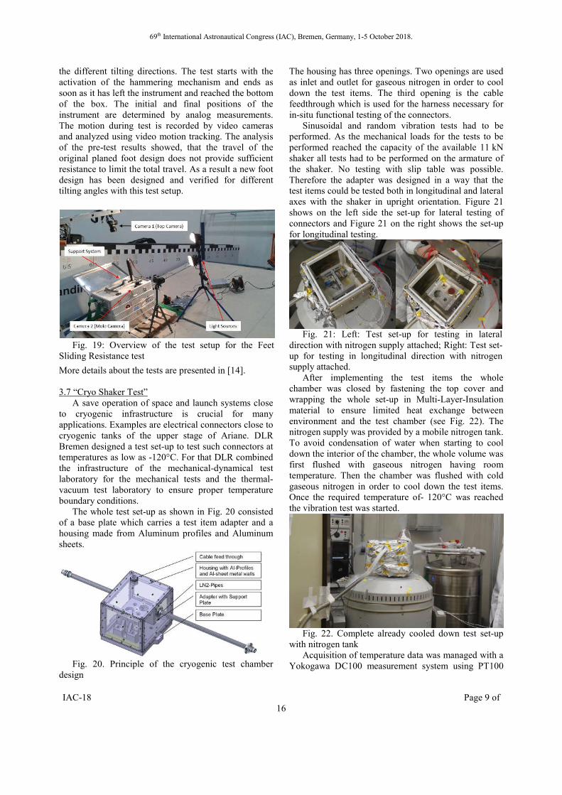
the different tilting directions. The test starts with the activation of the hammering mechanism and ends as soon as it has left the instrument and reached the bottom of the box. The initial and final positions of the instrument are determined by analog measurements. The motion during test is recorded by video cameras and analyzed using video motion tracking. The analysis of the pre-test results showed, that the travel of the original planed foot design does not provide sufficient resistance to limit the total travel. As a result a new foot design has been designed and verified for different tilting angles with this test setup.
More details about the tests are presented in [14]. 3.7 “Cryo Shaker Test”
A save operation of space and launch systems close to cryogenic infrastructure is crucial for many applications. Examples are electrical connectors close to cryogenic tanks of the upper stage of Ariane. DLR Bremen designed a test set-up to test such connectors at temperatures as low as -120°C. For that DLR combined the infrastructure of the mechanical-dynamical test laboratory for the mechanical tests and the thermal-vacuum test laboratory to ensure proper temperature boundary conditions.
The whole test set-up as shown in Fig. 20 consisted of a base plate which carries a test item adapter and a housing made from Aluminum profiles and Aluminum sheets.
Fig. 20. Principle of the cryogenic test chamber
design
The housing has three openings. Two openings are used as inlet and outlet for gaseous nitrogen in order to cool down the test items. The third opening is the cable feedthrough which is used for the harness necessary for in-situ functional testing of the connectors.
Sinusoidal and random vibration tests had to be performed. As the mechanical loads for the tests to be performed reached the capacity of the available 11 kN shaker all tests had to be performed on the armature of the shaker. No testing with slip table was possible. Therefore the adapter was designed in a way that the test items could be tested both in longitudinal and lateral axes with the shaker in upright orientation. Figure 21 shows on the left side the set-up for lateral testing of connectors and Figure 21 on the right shows the set-up for longitudinal testing.
Fig. 21: Left: Test set-up for testing in lateral
direction with nitrogen supply attached; Right: Test set-up for testing in longitudinal direction with nitrogen supply attached.
After implementing the test items the whole chamber was closed by fastening the top cover and wrapping the whole set-up in Multi-Layer-Insulation material to ensure limited heat exchange between environment and the test chamber (see Fig. 22). The nitrogen supply was provided by a mobile nitrogen tank. To avoid condensation of water when starting to cool down the interior of the chamber, the whole volume was first flushed with gaseous nitrogen having room temperature. Then the chamber was flushed with cold gaseous nitrogen in order to cool down the test items. Once the required temperature of- 120°C was reached the vibration test was started.
Fig. 22. Complete already cooled down test set-up
with nitrogen tank Acquisition of temperature data was managed with a
Yokogawa DC100 measurement system using PT100
Fig. 19: Overview of the test setup for the Feet Sliding Resistance test

69th International Astronautical Congress (IAC), Bremen, Germany, 1-5 October 2018.
IAC-18 Page 10 of 16
temperature sensors which are located on each test item. A cool down curve and temperature stability during the vibration test is shown in Figure 23. As no accelerometers for a temperature down to -120°C were available the excitation level inside the thermal chamber was not being measured during the presence of thermal environment. Therefore, the equivalent input level for two determined measurement points outside the chamber (Control 1, Control 2) was defined and verified by conducting pre-tests at room temperature. These pre-tests were divided in two steps:
1. Reverse Test: Accelerometers on the test items were in control loop and Control sensors 1 / 2 were measurement channels.
2. Verification Test: Control sensors 1 / 2 in control loop following the measured response from “Reverse Test” and test item sensors inside as measurement channels which shall show the required loads on the test items.
Fig. 23: Temperature profile during cool down and
vibration test The test chamber design including the selected
technique for test item cooling as well as the control strategy of the vibration loads, needed due to a lack of appropriate acceleration sensors, proved well suited for the successful execution of such kind of test.
3.8 MASCOT
The Mobile Asteroid Surface Scout (MASCOT) is a nano-scale asteroid lander aboard the JAXA asteroid sample-return mission, HAYABUSA2 (HY2), to asteroid (162173) Ryugu. [15] It is currently in the final landing preparations for its on-asteroid mission. MASCOT is a 9.8 kg, 29 · 28 · 21 cm³ self-contained small spacecraft carrying 4 fully fledged science instruments; though smaller in format, as many as its mothership, HY2. Next to a magnetometer with heritage from Mercury to Jupiter heliocentric distances [19], the instruments include a thermal IR multichannel radiometer, [20] a near- to mid-IR hyperspectral microscope, [21, 23] and a high dynamic range visual to near-IR range camera.
[22] Their performance is inherently sensitive to the thermal environment.
Also, to exclude as many environment-related risks as possible (cf. the PHILAE landing(s)’ experience [16]), MASCOT operates from a non-rechargeable Li-SOCl2 battery [17] and relies on a high degree of autonomy [18] to complete its scouting mission which is expected to cover 2 asteroid days of 7.6 hours, each. Due to the brief mission, there are few, if any, opportunities for ground-based intervention. The properties of long-term storable high-performance battery cells also depend decisively on the thermal conditions during storage and operation. The autonomous vehicle manager software has to derive certain trigger signals related to battery performance to adjust operations accordingly.
All these properties of the system components have to be thoroughly characterized in an as representative as possible environment, for dependable as well as optimized mission planning. The operating environment of MASCOT is further characterized by the very small gravity of the asteroid. Ryugu’s mass is not yet precisely known but the escape velocity will be of order few 10’s cm/s. Thus, all motions have to be very slow, and MASCOT has to separate from HY2 at 5 cm/s. This is not possible with separable structures stressed to withstand launch loads because their structural elasticity alone would already accelerate MASCOT to higher release velocities. Thus, structural retention pre-loads have to be released in flight, after launch and before separation.
The typical features and particular missions of MASCOT-like landers generally require non-standard development, qualification and characterization testing. [25, 26, 24] They are fundamentally constraints-driven designs in which the capabilities possible within the given design envelopes are at the same time margins on the minimum mission and to be fully utilized in extended mission phases and performance, leading to a very high efficiency in many aspects. For example, the net payload fraction of MASCOT is >31%. [15]
50
20
30
40
10
-20
-10
0
-40
-30
0 -10 -20 -30 -40 -50 -60 -70 -80 -90 10 -100
Se
para
tio
n
Sta
rt H
Y d
esc
en
t
Checkout and Release Preparation
MASCOT Preheating Home position
Sta
rt L
N2
pu
mp
ing
Masc
ot
ON
Time from MASCOT Separation [h]
Battery temperature
En
d o
f o
pera
tio
n
Heati
ng
MA
SC
OT a
nd
Ch
am
ber
Separation Preheating
Tem
per
atu
re [°C
]
20
Fig. 24: MASCOT On-Asteroid Thermal Vacuum Test Sequence

69th International Astronautical Congress (IAC), Bremen, Germany, 1-5 October 2018.
IAC-18 Page 11 of 16
3.8.1 MASCOT On-Asteroid TVAC Thus, in addition to the standard thermal vacuum
tests, MASCOT went through a thermal vacuum test simulating the asteroid thermal environment of the entire in-situ mission, preceded by a compressed but representative timeline of the delivery and pre-separation operations.
The objective of this test was to verify MASCOT operability under the dynamic thermal environment during the MASCOT on-asteroid operation phase as well as the pre-separation phase. Fig. 24 shows the overview of the thermal vacuum test flow, with the battery temperature as the reference point. At the beginning of the test, the vacuum chamber is pumped down and its shroud is cooled by LN2. MASCOT battery temperature is maintained by the survival heaters. After temperatures reach steady state conditions, the MASCOT system is pre-heated by changing the cruise survival heater set-point for preparing the MASCOT ON. Afterwards, MASCOT performs necessary pre-separation activities, including the battery maintenance and final check-out of each instrument. Before the separation, the battery is heated again to reach the optimal operational temperature, and then MASCOT starts operations for the release and on-asteroid phase.
This test required specific surrounding temperature control, which was realized by the support equipment shown in Fig. 25.
Fig. 25: MASCOT On-Asteroid Thermal Vacuum
Test Configuration
Heat inputs and temperature boundary conditions on the radiator and the single layer insulation (SLI) on each side were controlled by the test heaters. The temperature boundary condition on the bottom side was imitated by the boxed shape support equipment, named Soil Imitator. In addition, thermal impact to the payload compartment was imitated by the movable device, called +Y Gate. This equipment thermally protects MASCOT payloads during the pre-separation phase. After the MASCOT separation, it moves outwards and exposes the payloads to the external environment.
Fig. 26 shows the temperature control result of Soil Imitator, which has one of the most significant effects
on the MASCOT thermal behaviour. Because of the asteroid day-night cycle, the Soil Imitator temperature was required to be controlled dynamically during the asteroid phase. The result shows that the actual temperature followed target temperature and a MASCOT temperature sensor on the bottom side was clearly influenced by the surrounding environment.
Fig.: 26 Surrounding Temperature Control Result
3.8.2 MASCOT in-System Battery Characterization A series of battery characterization tests in table-top
setups, in, Climate Chamber, and in TVAC was conducted for MASCOT to determine the optimal operational parameters for its on-asteroid mission and the preceding battery management operations aboard HY2. The cell characteristics depend on the state of charge as well as ageing, and – compared to rechargeable batteries – are extremely dependent on the cell-internal temperature. At cell level, fresh cells had been already characterized by the project to guide the test planning. [27] By self-heating during discharge, which is load-dependent and also dependent on temperature and state of charge, the cell properties feedback on themselves in that cell and its thermally connected neighbours, creating a complex cross-coupled system also influenced by the dissipation of the various power-consuming units. Thus, regimes of operation had to be confirmed or found in which the battery as a whole is at the same time operating efficiently and in a stable thermal evolution.
The first tests included a unit-level Battery TVAC to characterize the self-heating of and thermal coupling between the 9 individual battery cells of a flight-like MASCOT Battery, using the full standard Pt100 thermal sensor channels capability of the SSA vacuum chamber plus the 4 thermal sensors of the battery itself. This test identified the locations most indicative of the relevant temperatures and heat flow paths.
Due to the nano-scale construction of MASCOT, thermal coupling between all subsystems can be expected and indeed does occur at relevant levels to some extent. Thus, almost all battery-related testing was conducted using the fully integrated MASCOT Flight Spare (FS) which is a 1:1 copy of the MASCOT Flight Model (FM) in space. It was equipped with flight-like
69th International Astronautical Congress (IAC), Bremen, Germany, 1-5 October 2018.
IAC-18 Page 12 of 16
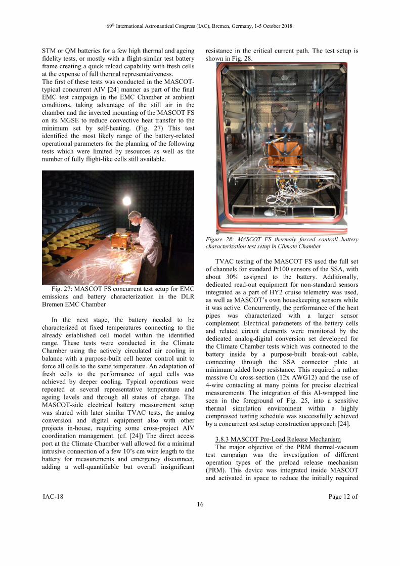
STM or QM batteries for a few high thermal and ageing fidelity tests, or mostly with a flight-similar test battery frame creating a quick reload capability with fresh cells at the expense of full thermal representativeness. The first of these tests was conducted in the MASCOT-typical concurrent AIV [24] manner as part of the final EMC test campaign in the EMC Chamber at ambient conditions, taking advantage of the still air in the chamber and the inverted mounting of the MASCOT FS on its MGSE to reduce convective heat transfer to the minimum set by self-heating. (Fig. 27) This test identified the most likely range of the battery-related operational parameters for the planning of the following tests which were limited by resources as well as the number of fully flight-like cells still available.
Fig. 27: MASCOT FS concurrent test setup for EMC
emissions and battery characterization in the DLR Bremen EMC Chamber
In the next stage, the battery needed to be characterized at fixed temperatures connecting to the already established cell model within the identified range. These tests were conducted in the Climate Chamber using the actively circulated air cooling in balance with a purpose-built cell heater control unit to force all cells to the same temperature. An adaptation of fresh cells to the performance of aged cells was achieved by deeper cooling. Typical operations were repeated at several representative temperature and ageing levels and through all states of charge. The MASCOT-side electrical battery measurement setup was shared with later similar TVAC tests, the analog conversion and digital equipment also with other projects in-house, requiring some cross-project AIV coordination management. (cf. [24]) The direct access port at the Climate Chamber wall allowed for a minimal intrusive connection of a few 10’s cm wire length to the battery for measurements and emergency disconnect, adding a well-quantifiable but overall insignificant
resistance in the critical current path. The test setup is shown in Fig. 28.
Figure 28: MASCOT FS thermaly forced controll battery characterization test setup in Climate Chamber
TVAC testing of the MASCOT FS used the full set of channels for standard Pt100 sensors of the SSA, with about 30% assigned to the battery. Additionally, dedicated read-out equipment for non-standard sensors integrated as a part of HY2 cruise telemetry was used, as well as MASCOT’s own housekeeping sensors while it was active. Concurrently, the performance of the heat pipes was characterized with a larger sensor complement. Electrical parameters of the battery cells and related circuit elements were monitored by the dedicated analog-digital conversion set developed for the Climate Chamber tests which was connected to the battery inside by a purpose-built break-out cable, connecting through the SSA connector plate at minimum added loop resistance. This required a rather massive Cu cross-section (12x AWG12) and the use of 4-wire contacting at many points for precise electrical measurements. The integration of this Al-wrapped line seen in the foreground of Fig. 25, into a sensitive thermal simulation environment within a highly compressed testing schedule was successfully achieved by a concurrent test setup construction approach [24].
3.8.3 MASCOT Pre-Load Release Mechanism The major objective of the PRM thermal-vacuum
test campaign was the investigation of different operation types of the preload release mechanism (PRM). This device was integrated inside MASCOT and activated in space to reduce the initially required

69th International Astronautical Congress (IAC), Bremen, Germany, 1-5 October 2018.
IAC-18 Page 13 of 16
preload force of ca. 3 kN for the successful MASCOT launch phase in order to withstand high mechanical loads. The initially adjusted force should be significantly reduced to provide a smooth separation of the landing module from the main HAYABUSA2 space craft. The preload force reduction was realised with the aid of a thermal melting process, as a result of the PRM activation in space.
After the major preload force reduction to the required rest force, during the cruise phase to the destination and before the separation process, the rest force significantly changes due to the thermal cycles within the landing module. The rest force will be either increased due to the thermal expansion at increasing ambient temperature or decreased by thermal shrinking caused by environmental cooling within MASCOT. In order to define the best feasible rest preload force setting for the cruise phase and the final separation process, several PRM activation processes under consideration of different thermal conditions were simulated, which were close to the real space conditions during the flight.
The qualification thermal-vacuum test campaign was performed inside the SSA facility, see Fig. 29. The simulated space environmental conditions were realized by the aid of the thermally regulated vacuum chamber, where the controlled melting of the thermoplastic material inside the preload release mechanism, in consequence of the PRM activation was performed.
Fig. 29: Overview of the PRM TVAC test setup.
The chamber pressure during the test phase was reduced to p ≤ 10-4 mbar, and the simulated ambient temperature was -55°C to meet the cold case and +65°C for the hot case, to cover expected thermal cycles during the space flight, as shown in Fig. 30. The measured parameters of the PRM, such as the temperature of the molten thermoplastic, the clamping force and the electrical contacts response of the PRM was recorded by the data acquisition system to verify the system level requirements, shown in figure 3.5c.
Fig. 30: Simplified expected thermal cycles for the
PRM qualification test campaign.
Fig.: 31: Processed PRM parameters to verify the system level requirements for the MASCOT mission. 3.9 Eu:CROPIS On-Orbit Simulation Test
EU:CROPIS (Euglena Combined Regenerative Organic Food Production in Space) is a compact satellite project of the DLR Institute of Space Systems in Bremen. Eu:CROPIS was built to demonstrate a closed life support system (CLSS) that can be operated and reinitiated under various gravity conditions (Moon and Mars). The satellite’s dimensions were 1100x1100x1300mm (lenght x width x height) with a total mass of 233kg.
To demonstrate the survivability of the satellite during a full-autonomous operation in the LEOP (Launch and Early Orbit Phase) an on-orbit simulation was carried out in the Space Simulation Chamber with
69th International Astronautical Congress (IAC), Bremen, Germany, 1-5 October 2018.
IAC-18 Page 14 of 16
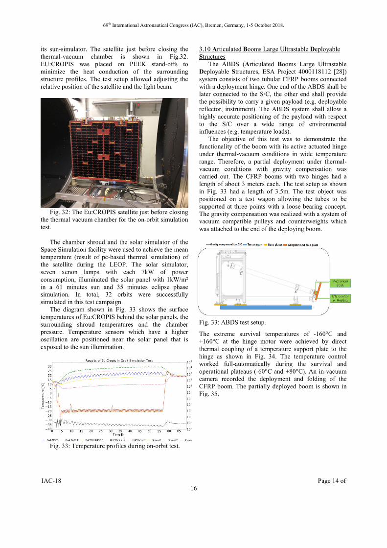
its sun-simulator. The satellite just before closing the thermal-vacuum chamber is shown in Fig.32. EU:CROPIS was placed on PEEK stand-offs to minimize the heat conduction of the surrounding structure profiles. The test setup allowed adjusting the relative position of the satellite and the light beam.
Fig. 32: The Eu:CROPIS satellite just before closing
the thermal vacuum chamber for the on-orbit simulation test.
The chamber shroud and the solar simulator of the
Space Simulation facility were used to achieve the mean temperature (result of pc-based thermal simulation) of the satellite during the LEOP. The solar simulator, seven xenon lamps with each 7kW of power consumption, illuminated the solar panel with 1kW/m² in a 61 minutes sun and 35 minutes eclipse phase simulation. In total, 32 orbits were successfully simulated in this test campaign.
The diagram shown in Fig. 33 shows the surface temperatures of Eu:CROPIS behind the solar panels, the surrounding shroud temperatures and the chamber pressure. Temperature sensors which have a higher oscillation are positioned near the solar panel that is exposed to the sun illumination.
Fig. 33: Temperature profiles during on-orbit test.
3.10 Articulated Booms Large Ultrastable Deployable Structures
The ABDS (Articulated Booms Large Ultrastable Deployable Structures, ESA Project 4000118112 [28]) system consists of two tubular CFRP booms connected with a deployment hinge. One end of the ABDS shall be later connected to the S/C, the other end shall provide the possibility to carry a given payload (e.g. deployable reflector, instrument). The ABDS system shall allow a highly accurate positioning of the payload with respect to the S/C over a wide range of environmental influences (e.g. temperature loads).
The objective of this test was to demonstrate the functionality of the boom with its active actuated hinge under thermal-vacuum conditions in wide temperature range. Therefore, a partial deployment under thermal-vacuum conditions with gravity compensation was carried out. The CFRP booms with two hinges had a length of about 3 meters each. The test setup as shown in Fig. 33 had a length of 3.5m. The test object was positioned on a test wagon allowing the tubes to be supported at three points with a loose bearing concept. The gravity compensation was realized with a system of vacuum compatible pulleys and counterweights which was attached to the end of the deploying boom.
Fig. 33: ABDS test setup.
The extreme survival temperatures of -160°C and +160°C at the hinge motor were achieved by direct thermal coupling of a temperature support plate to the hinge as shown in Fig. 34. The temperature control worked full-automatically during the survival and operational plateaus (-60°C and +80°C). An in-vacuum camera recorded the deployment and folding of the CFRP boom. The partially deployed boom is shown in Fig. 35.

69th International Astronautical Congress (IAC), Bremen, Germany, 1-5 October 2018.
IAC-18 Page 15 of 16
Fig. 34: Thermal coupling of the hinge in order to reach -160°C and +160°C.
Fig. 35: Partially deployed boom after test.
4. CONCLUSIONS AND OUTLOOK
Within several activities space hardware was brought to TRL 5 and 6 with the required environmental testing. This often required special test setups, especially when handling deployable components.
Another challenge is material testing under space radiation environment. Test campaigns that aimed for an aging analysis of coated thin-films were carried out considering electromagnetic radiation as well as corpuscular radiation and atomic oxygen.
With the projects MASCOT, Insight and Eu:CROPIS the next demonstrations in space and on mars are ahead. In ADEO-2 a PFM drag sail is now build with industry partners in an ESA GSTP project. DLR’s GoSolAr project is now focusing on the development of large deployable photovoltaic arrays which will require all expertise in the field of environmental testing, ranging from material and component level up to system level testing.
The test facilities are constantly improved. Within the ongoing activities the camera system in the space simulation chamber will be updated. Here it is also intended to use an infrared camera during test in order to evaluate for example temperature distributions
through the test object. Within an ongoing cooperation with NASA Langley Research Center (LaRC) DLR looks further into the aging of solar sail material which will include the measurement of specular reflectance in addition to the thermo-optical properties. For photovoltaic qualification and characterisation the test facilities are adapted for AM0 characterization and evaluation of the photovoltaic behaviour under radiation environment.
ACKNOLOGEMENTS
We are thanking all partners for good and fruitful cooperation.
REFERENCES
[1] DLR, Institute of Space Systems, http://www.dlr.de/irs/en (accessed 21.08.16).
[2] DLR, Institute of Space Systems, Test Facilities, https://www.dlr.de/irs/Portaldata/46/Resources/2015_dokumente/mts_test_facilities_engl_2016_06_13/MTS_Test_Facilities_engl_2016-08-26.pdf (accessed 21.069.16).
[3] T. Renger, M. Sznajder, A. Witzke, U. Geppert, The Complex Irradiation Facility at DLR-Bremen, Journal of Materials Science and Engineering A. 4 (2014): 1-9.
[4] M. Sznajder, U. Geppert, M. Dudek, Degradation of metallic surfaces under space conditions, with particular emphasis on Hydrogen recombination processes, Advances in Space Research. 56 (2015) 71-84.
[5] M. Sznajder, U. Geppert, M. Dudek, Hydrogen blistering under extreme radiation conditions, npj Materials Degradation. 2 (2018) 1-8
[6] P. Seefeldt, P. Spietz, T. Spröwitz et al., Gossamer-1: Mission concept and technology for a controlled deployment of gossamer spacecraft, Advances in Space Research. 59.1 (2016): 434-456
[7] P. Seefeldt. A stowing and deployment strategy for large membrane space systems on the example of Gossamer-1, Advances in Space Research. 60.6 (2017): 1345-1362
[8] P. Seefeldt, T. Spröwitz, J.-T. Grundmann. Verification Testing of the Gossamer-1 Deployment Demonstrator, IAC 2016
[9] M. Sznajder, U. Geppert, M. Dudek. Degradation of metallic surfaces under space conditions, with particular emphasis on Hydrogen recombination processes, Advances in Space Research. 56 (2015) 71-84.
[10] M. Sznajder, U. Geppert, M. Dudek, Hydrogen blistering under extreme radiation conditions, npj Materials Degradation. 3 (2018) 1-8
[11] European Cooperation for Space Standardization, ECSS-Q-ST-70-06C, Particle and UV radiation testing for space materials, 2008.

69th International Astronautical Congress (IAC), Bremen, Germany, 1-5 October 2018.
IAC-18 Page 16 of 16
[12] M. Sznajder, T. Renger, A. Witzke et al., Design and performance of a vacuum-UV simulator for material testing under space conditions, Advances in Space Research. 52 (2013): 1993-2005.
[13] T. Sinn, P. Seefeldt, A. Riemer et al. Design, Analysis and Testing of the ADEO Passive De-Orbit Subsystem Demonstrator. Proceedings of the14th European Conference on Spacecraft Structures, Materials and Environmental Testing (ECSSMET), 2016
[14] S. Reershemius, M. Fittock, T. Spröwitz et al. Development of the Support System Used on the HP3 Instrument for Insight Mars Mission, ECSSMET 2016
[15] Tra-Mi Ho, Volodymyr Baturkin, Christian Grimm, Jan Thimo Grundmann, et al. MASCOT - The Mobile Asteroid Surface Scout Onboard the HAYABUSA2 Mission; Space Science Reviews, 2016, DOI 10.1007/s11214-016-0251-6
[16] J. Biele, S. Ulamec, M. Maibaum, et al. The landing(s) of Philae and inferences about comet surface mechanical properties, Science, Vol.349, issue 6247, aaa9816-1 (2015).
[17] J.T. Grundmann, J. Biele, R. Findlay et al. One Shot to an Asteroid – MASCOT and the Design of an Exclusively Primary Battery Powered Small Spacecraft in Hardware Design Examples and Operational Considerations, № 3051, European Space Power Conference 2014
[18] F. Cordero, J. Marx, E. Baumstark et al. MASCOT lander operational concept and its autonomy, general services and resource optimisation implementation in the on-board software, 14th International Conference on Space Operations, 2016, ISBN 9781624104268
[19] D. Herčík, H.-U. Auster, J. Blum et al. The MASCOT Magnetometer; Space Science Reviews, 2016, DOI 10.1007/s11214-016-0236-5
[20] M. Grott, J. Knollenberg, B. Borgs et al. The MASCOT Radiometer MARA for the Hayabusa 2 Mission, Space Science Reviews, 2016, DOI 10.1007/s11214-016-0272-1
[21] J.-P. Bibring, V. Hamm, Y. Langevin et al. The MicrOmega investigation onboard Hayabusa2. Space Sci. Rev. 208, 401-412 (2017)
[22] R. Jaumann, N. Schmitz, A. Koncz, et al. The Camera of the MASCOT Asteroid Lander on Board Hayabusa2; Space Science Reviews, 2016, DOI 10.1007/s11214-016-0263-2
[23] L. Riu, J-P. Bibring, V. Hamm, et al., Calibration of MicrOmega Hayabusa-2 Flight Model – First Results, 47th LPSC 2016, #2109.
[24] C.D. Grimm, J.T. Grundmann, J. Hendrikse, et al. From Idea to Flight – A Review of the MASCOT Development and a Comparison to Historical Fast-
Paced Space Programs, 2018, Progress in Aerospace Sciences (submitted)
[25] C. Lange, J. Biele, S. Ulamec et al. MASCOT2 –
A small body lander to investigate the interior of 65803 Didymos′ moon in the frame of the
AIDA/AIM mission, Acta Astronautica 149 (2018) 25–34.
[26] C. Lange, T.-M. Ho, C. Grimm et al. Exploring Small Bodies: Nano- and microlander options derived from the Mobile Asteroid Surface Scout, 2018, Advances in Space Research.
[27] Elisabet Wejmo. Development of an Algorithm to Estimate the Remaining Energy of a Primary Battery During an Autonomous Asteroid Mission, Luleå University of Technology, Master Thesis, August 2014.
[27] Elisabet Wejmo. Development of an Algorithm to Estimate the Remaining Energy of a Primary Battery During an Autonomous Asteroid Mission, Luleå University of Technology, Master Thesis, August 2014.
[28]European Space Agency (ESA), Articulated Booms Large Ultrastable Deployable Structures (ABDS), http://www.esa.int/spaceinimages/Images/2018/08/Shaker_testing_of_an_articulated_deployable_boom_demonstrator, (accessed 31.08.16).