Embed Size (px)
Citation preview
Page 1 of 13
TECHNICAL APPROVALS FOR CONSTRUCTION
APPROVAL
INSPECTION
TESTING
CERTIFICATION
Specialist Building Products Ltdt/a KestrelBceBillet LaneNormanby Enterprise ParkNormanby RoadScunthorpeNorth Lincolnshire DN15 9YHTel: 01724 400440 Fax: 01724 280241e-mail: [email protected]: www.kestrelbce.co.uk
British Board of Agrément tel: 01923 665300Bucknalls Lane fax: 01923 665301Watford [email protected] WD25 9BA www.bbacerts.co.uk©2015
The BBA is a UKAS accredited certification body — Number 113. The schedule of the current scope of accreditation for product certification is available in pdf format via the UKAS link on the BBA website at www.bbacerts.co.uk
Readers are advised to check the validity and latest issue number of this Agrément Certificate by either referring to the BBA website or contacting the BBA direct.
SPECIALIST BUILDING PRODUCTS CLADDING SYSTEMS
KESTREL PVC-UE CLADDING SYSTEM
This Agrément Certificate Product Sheet(1) relates to the Kestrel PVC-UE Cladding System, comprising white PVC-UE cladding planks and PVC-U trims for use on external walls of buildings as a decorative and protective facing fixed either horizontally, vertically or diagonally.(1) Hereinafter referred to as ‘Certificate’.
CERTIFICATION INCLUDES:• factors relating to compliance with Building
Regulations where applicable• factors relating to additional non-regulatory
information where applicable• independently verified technical specification• assessment criteria and technical investigations• design considerations• installation guidance• regular surveillance of production• formal three-yearly review.
KEY FACTORS ASSESSEDStrength and stability — when installed in accordance with the requirements of this Certificate, onto battens at 600 mm spacings, the cladding can withstand dynamic wind pressures shown in Table 2 (see section 6).
Performance in relation to fire —the system achieved a reaction to fire classification* of D-s3, d2/(AVM) to BS EN 13501-1 : 2007 (see section 7).
Durability — the system will retain its decorative qualities for a period in excess of 35 years with only minor changes in surface appearance and will retain adequate impact resistance for a period of 35 years (see section 11).
Agrément Certificate11/4839
Product Sheet 1
The BBA has awarded this Certificate to the company named above for the system described herein. This system has been assessed by the BBA as being fit for its intended use provided it is installed, used and maintained as set out in this Certificate.
On behalf of the British Board of Agrément
Date of Second issue: 16 September 2015 John Albon — Head of Approvals Claire Curtis-Thomas
Originally certificated on 11 July 2011 Construction Products Chief Executive
Page 2 of 13
In the opinion of the BBA, the Kestrel PVC-UE Cladding System, if installed, used and maintained in accordance with this Certificate, can satisfy or contribute to satisfying the relevant requirements of the following Building Regulations (the presence of a UK map indicates that the subject is related to the Building Regulations in the region or regions of the UK depicted):
The Building Regulations 2010 (England and Wales) (as amended)
Requirement: A1 Loading
Comment: The system is acceptable for use as set out in sections 4.2 to 4.4 and 6.1 to 6.5 of this Certificate.Requirement: B3(2)(4) Internal fire spread (structure)Requirement: B4(1) External fire spread
Comment: The system achieved a reaction to fire classification* of D-s3, d2/(AVM) and so its use is restricted under this Requirement. See sections 7.1 to 7.4 of this Certificate.
Requirement: C2(b)(c) Resistance to moisture
Comment: The system does not form a watertight or airtight facing. To achieve a waterproof barrier on exposed substrates a breather membrane must be provided. See sections 4.7 and 8 of this Certificate.
Regulation: 7 Materials and workmanship
Comment: The system is acceptable. See section 11.1 and the Installation part of this Certificate.
The Building (Scotland) Regulations 2004 (as amended)
Regulation: 8(1)(2) Durability, workmanship and fitness of materials
Comment: The system is acceptable. See sections 10 and 11.1 and the Installation part of this Certificate.Regulation: 9 Building standards applicable to constructionStandard: 1.1(a)(b) Structure
Comment: The system can contribute to satisfying this Standard, with reference to clause 1.1.1(1)(2) as set out in sections 4.2 to 4.4 and 6.1 to 6.5 of this Certificate.
Standard: 2.4 CavitiesStandard: 2.6 Spread to neighbouring buildingsStandard: 2.7 Spread on external walls
Comment: The system is restricted by these Standards, with reference to clauses, 2.4.2(1)(2), 2.4.4(1), 2.4.7(1), 2.4.9(2), 2.6.2(1)(2), 2.6.4(1)(2), and 2.7.1(1)(2) respectively as set out in sections 7.1 to 7.3 and 7.5 of this Certificate.
Standard: 3.10 Precipitation
Comment: The system does not form a watertight or airtight facing. To achieve a weatherproof barrier on exposed substrates, a breather membrane must be provided. See section 8 of this Certificate.
Standard: 3.15 Condensation
Comment: Provided there is provision for adequate drainage and ventilation behind the cladding, and a breather membrane is incorporated, as required, the system can contribute to satisfying this Standard, with reference to clauses 3.15.4(1) and 3.15.5(1). See sections 4.7 and 8 of this Certificate.
Standard: 7.1(a) Statement of sustainability
Comment: The system can contribute to satisfying the relevant requirements of Regulation 9, Standards 1 to 6, and, therefore, will contribute to a construction meeting a bronze level of sustainability as defined in this Standard.
Regulation: 12 Building standards applicable to conversions
Comment: All comments given for this system under Regulation 9, Standards 1 to 6, also apply to this Regulation, with reference to clause 0.12.1(1)(2) and Schedule 6(1)(2).
(1) Technical Handbook (Domestic). (2) Technical Handbook (Non-Domestic).
The Building Regulations (Northern Ireland) 2012 (as amended)
Regulation: 23 Fitness of materials and workmanship
Comment: The system is acceptable. See section 11.1 and the Installation part of this Certificate.Regulation: 28(b) Resistance to moisture and weather
Comment: The system does not form a watertight or airtight facing. To achieve a weatherproof barrier on exposed substrates, a breather membrane must be provided. See sections 4.7 and 8 of this Certificate.
Regulation: 29 Condensation
Comment: Provided there is provision for adequate drainage and ventilation behind the cladding, and a breather membrane is incorporated, as required, the system can contribute to satisfying this Standard. See sections 4.7 and 8 of this Certificate.
Regulation: 30 Stability
Comment: The system is acceptable for use as set out in sections 4.2 to 4.4 and 6.1 to 6.5 of this Certificate.Regulation: 35(2)(3) Internal fire spread — StructureRegulation: 36(a) External fire spread
Comment: The system achieved a reaction to fire classification* of D-s3, d2/(AVM) and so its use is restricted under this Regulation. See sections 7.1 to 7.4 of this Certificate.
Regulations
Page 3 of 13
Construction (Design and Management) Regulations 2015
Construction (Design and Management) Regulations (Northern Ireland) 2007
Information in this Certificate may assist the client, Principal Designer/CDM co-ordinator, designer and contractors to address their obligations under these Regulations.See section: 13 General (13.4) of this Certificate.
Additional Information
NHBC Standards 2014NHBC accepts the use of Kestrel PVC-UE Cladding System provided it is installed, used and maintained in accordance with this Certificate, in relation to NHBC Standards, Part 6 Substructure (excluding roofs) Chapter 6.1 External masonry walls (section D14 — Cladding) and Chapter 6.2 External timber framed walls.
CE markingThe Certificate holder has taken the responsibility of CE marking the system, in accordance with harmonised European Standard BS EN 13245 : 2008. An asterisk (*) appearing in this Certificate indicates that data shown are given in the manufacturer’s Declaration of Performance.
Technical Specification
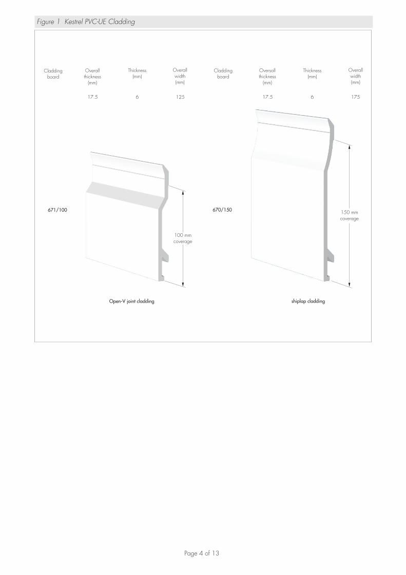
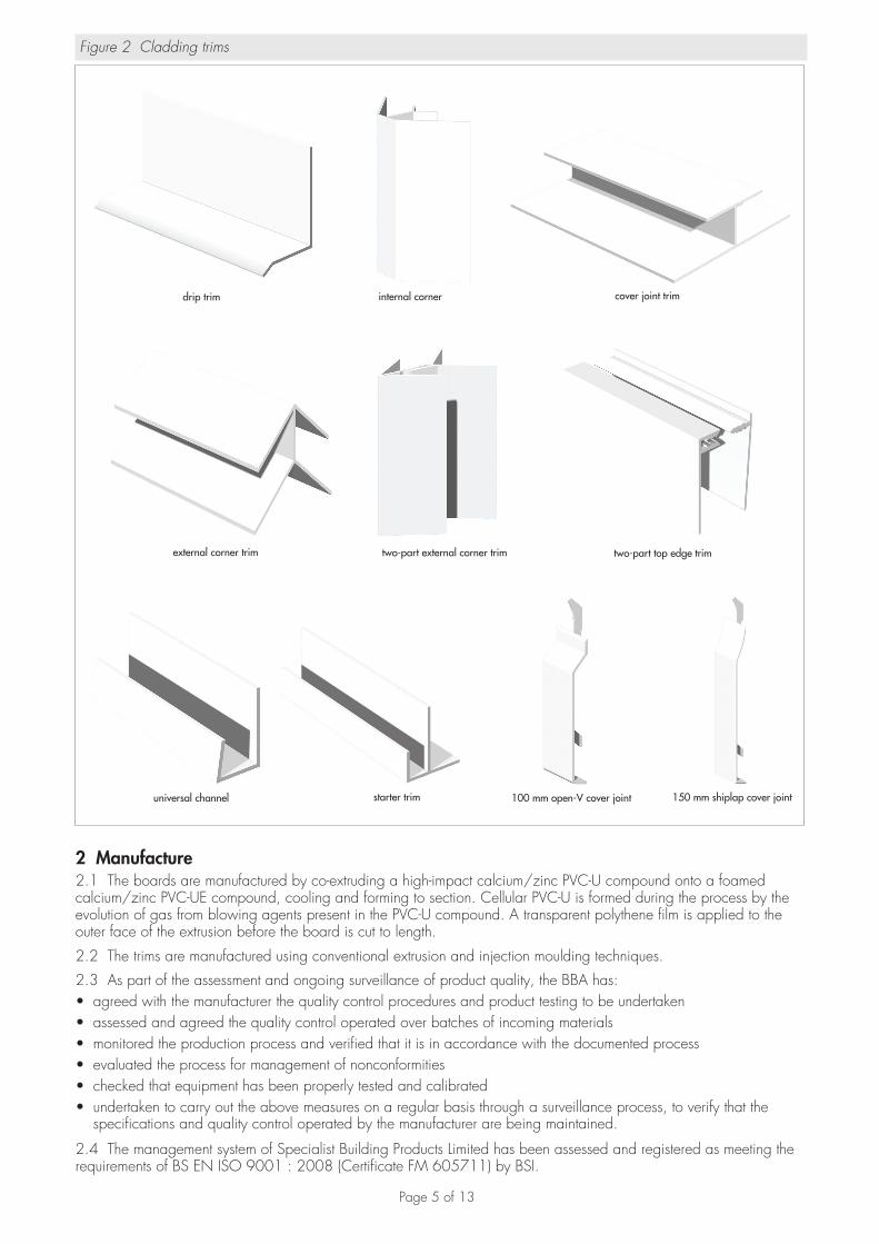
1 Description1.1 The Kestrel PVC-UE Cladding System comprises white PVC-UE cladding planks with matching rigid PVC-U trims (see Figures 1 and 2). The components of the system are available in three shades of white: standard white, dove and brilliant white.
1.2 The planks are composed of a cellular PVC-U core beneath an impact modified, outer weathering PVC-U skin. The trims consist of extrusions in impact modified PVC-U or injection mouldings in PVC-U.
1.3 The planks are available in two designs, Open-V and Shiplap, with the characteristics given in Table 1.
Table 1 Characteristics of planks
Characteristics (units) Open-V Shiplap
Standard length (m) 5 5
Cover width (mm) 100 150
Nominal thickness (mm) 6 6
Nominal thickness of rigid outer surface (mm) 0.6 0.6
Nominal weight per metre (kg·m–1) 0.49 0.63
Average density (kg·m–3) 420 420
1.4 Ancillary items specified for use with the system but outside the scope of this Certificate include:• stainless steel, annular ring-shank pins (2.0 mm shank diameter) — used to secret fix cladding planks and extruded
trims to timber studs or battens. Sizes available are 30 mm by 2 mm (used to fix planks to studs, or to battens with cross-sections not less than 19 mm by 38 mm) and 25 mm (used to fix planks to battens with cross-sections less than 19 mm by 38 mm) and 20 mm by 2 mm (used to fix trims)
• breather membrane — for use with the system on non weathertight substrates• timber battens — preservative treated to provide support for cladding.
Page 4 of 13
Figure 1 Kestrel PVC-UE Cladding
Claddingboard
Overallthickness
(mm)
Thickness(mm)
Overallwidth(mm)
Claddingboard
Oversallthickness
(mm)
Thickness(mm)
Overallwidth(mm)
671/100
17.5 6 125
670/150
17.5 6 175
100 mmcoverage
150 mmcoverage
Open-V joint cladding shiplap cladding
Page 5 of 13
Figure 2 Cladding trims
drip trim internal corner cover joint trim
external corner trim two-part external corner trim two-part top edge trim
universal channel starter trim 100 mm open-V cover joint 150 mm shiplap cover joint
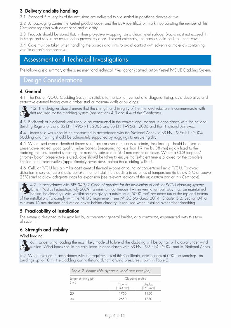
2 Manufacture2.1 The boards are manufactured by co-extruding a high-impact calcium/zinc PVC-U compound onto a foamed calcium/zinc PVC-UE compound, cooling and forming to section. Cellular PVC-U is formed during the process by the evolution of gas from blowing agents present in the PVC-U compound. A transparent polythene film is applied to the outer face of the extrusion before the board is cut to length.
2.2 The trims are manufactured using conventional extrusion and injection moulding techniques.
2.3 As part of the assessment and ongoing surveillance of product quality, the BBA has:• agreed with the manufacturer the quality control procedures and product testing to be undertaken• assessed and agreed the quality control operated over batches of incoming materials• monitored the production process and verified that it is in accordance with the documented process• evaluated the process for management of nonconformities• checked that equipment has been properly tested and calibrated• undertaken to carry out the above measures on a regular basis through a surveillance process, to verify that the
specifications and quality control operated by the manufacturer are being maintained.
2.4 The management system of Specialist Building Products Limited has been assessed and registered as meeting the requirements of BS EN ISO 9001 : 2008 (Certificate FM 605711) by BSI.
Page 6 of 13
3 Delivery and site handling3.1 Standard 5 m lengths of the extrusions are delivered to site sealed in polythene sleeves of five.
3.2 All packaging carries the Kestrel product code, and the BBA identification mark incorporating the number of this Certificate together with description and quantity.
3.3 Products should be stored flat, in their protective wrapping, on a clean, level surface. Stacks must not exceed 1 m in height and should be restrained to prevent collapse. If stored externally, the packs should be kept under cover.
3.4 Care must be taken when handling the boards and trims to avoid contact with solvents or materials containing volatile organic components.
Assessment and Technical Investigations
The following is a summary of the assessment and technical investigations carried out on Kestrel PVC-UE Cladding System.
Design Considerations
4 General4.1 The Kestrel PVC-UE Cladding System is suitable for horizontal, vertical and diagonal fixing, as a decorative and protective external facing over a timber stud or masonry walls of buildings.
4.2 The designer should ensure that the strength and integrity of the intended substrate is commensurate with that required for the cladding system (see sections 4.3 and 4.4 of this Certificate).
4.3 Brickwork or blockwork walls should be constructed in the conventional manner in accordance with the national Building Regulations and BS EN 1996-1-1 : 2005 and BS EN 1996-3 : 2006 and their National Annexes.
4.4 Timber stud walls should be constructed in accordance with the National Annex to BS EN 1995-1-1 : 2004. Studding and framing should be adequately supported by noggings to ensure rigidity.
4.5 When used over a sheathed timber stud frame or over a masonry substrate, the cladding should be fixed to preservative-treated, good quality timber battens (measuring not less than 19 mm by 38 mm) rigidly fixed to the studding (not unsupported sheathing) or masonry substrate at 600 mm centres or closer. Where a CCB (copper/chrome/boron) preservative is used, care should be taken to ensure that sufficient time is allowed for the complete fixation of the preservative (approximately seven days) before the cladding is fixed.
4.6 Cellular PVC-U has a similar coefficient of thermal expansion to that of conventional rigid PVC-U. To avoid distortion in service, care should be taken not to install the cladding in extremes of temperature (ie below 5ºC or above 25ºC) and to allow adequate gaps for expansion (see relevant sections of the Installation part of this Certificate).
4.7 In accordance with BPF 349/2 Code of practice for the installation of cellular PVC-U cladding systems (British Plastics Federation, July 2009), a minimum continuous 19 mm ventilation pathway must be maintained behind the cladding, with ventilation slots giving a minimum of 5000 mm2 per metre run at the top and bottom
of the installation. To comply with the NHBC requirement (see NHBC Standards 2014, Chapter 6.2, Section D4) a minimum 15 mm drained and vented cavity behind cladding is required when installed over timber sheathing.
5 Practicability of installationThe system is designed to be installed by a competent general builder, or a contractor, experienced with this type of system.
6 Strength and stabilityWind loading
6.1 Under wind loading the most likely mode of failure of the cladding will be by nail withdrawal under wind suction. Wind loads should be calculated in accordance with BS EN 1991-1-4 : 2005 and its National Annex.
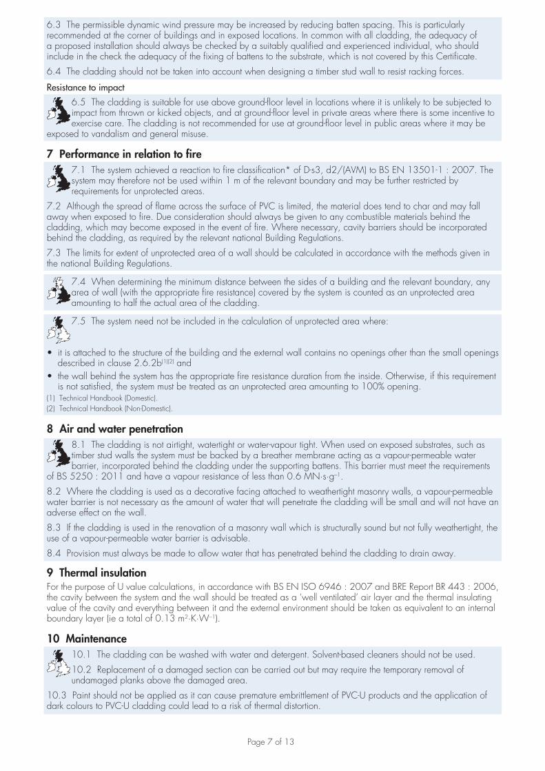
6.2 When installed in accordance with the requirements of this Certificate, onto battens at 600 mm spacings, on buildings up to 10 m, the cladding can withstand dynamic wind pressures shown in Table 2.
Table 2 Permissible dynamic wind pressures (Pa)
Length of fixing pin(mm)
Cladding profile
Open-V(100 mm)
Shiplap(150 mm)
25 1750 1150
30 2650 1750
Page 7 of 13
6.3 The permissible dynamic wind pressure may be increased by reducing batten spacing. This is particularly recommended at the corner of buildings and in exposed locations. In common with all cladding, the adequacy of a proposed installation should always be checked by a suitably qualified and experienced individual, who should include in the check the adequacy of the fixing of battens to the substrate, which is not covered by this Certificate.
6.4 The cladding should not be taken into account when designing a timber stud wall to resist racking forces.
Resistance to impact
6.5 The cladding is suitable for use above ground-floor level in locations where it is unlikely to be subjected to impact from thrown or kicked objects, and at ground-floor level in private areas where there is some incentive to exercise care. The cladding is not recommended for use at ground-floor level in public areas where it may be
exposed to vandalism and general misuse.
7 Performance in relation to fire7.1 The system achieved a reaction to fire classification* of D-s3, d2/(AVM) to BS EN 13501-1 : 2007. The system may therefore not be used within 1 m of the relevant boundary and may be further restricted by requirements for unprotected areas.
7.2 Although the spread of flame across the surface of PVC is limited, the material does tend to char and may fall away when exposed to fire. Due consideration should always be given to any combustible materials behind the cladding, which may become exposed in the event of fire. Where necessary, cavity barriers should be incorporated behind the cladding, as required by the relevant national Building Regulations.
7.3 The limits for extent of unprotected area of a wall should be calculated in accordance with the methods given in the national Building Regulations.
7.4 When determining the minimum distance between the sides of a building and the relevant boundary, any area of wall (with the appropriate fire resistance) covered by the system is counted as an unprotected area amounting to half the actual area of the cladding.
7.5 The system need not be included in the calculation of unprotected area where:
• it is attached to the structure of the building and the external wall contains no openings other than the small openings described in clause 2.6.2b(1)(2) and
• the wall behind the system has the appropriate fire resistance duration from the inside. Otherwise, if this requirement is not satisfied, the system must be treated as an unprotected area amounting to 100% opening.
(1) Technical Handbook (Domestic).(2) Technical Handbook (Non-Domestic).
8 Air and water penetration8.1 The cladding is not airtight, watertight or water-vapour tight. When used on exposed substrates, such as timber stud walls the system must be backed by a breather membrane acting as a vapour-permeable water barrier, incorporated behind the cladding under the supporting battens. This barrier must meet the requirements
of BS 5250 : 2011 and have a vapour resistance of less than 0.6 MN·s·g–1.
8.2 Where the cladding is used as a decorative facing attached to weathertight masonry walls, a vapour-permeable water barrier is not necessary as the amount of water that will penetrate the cladding will be small and will not have an adverse effect on the wall.
8.3 If the cladding is used in the renovation of a masonry wall which is structurally sound but not fully weathertight, the use of a vapour-permeable water barrier is advisable.
8.4 Provision must always be made to allow water that has penetrated behind the cladding to drain away.
9 Thermal insulationFor the purpose of U value calculations, in accordance with BS EN ISO 6946 : 2007 and BRE Report BR 443 : 2006, the cavity between the system and the wall should be treated as a ‘well ventilated’ air layer and the thermal insulating value of the cavity and everything between it and the external environment should be taken as equivalent to an internal boundary layer (ie a total of 0.13 m2·K·W–1).
10 Maintenance10.1 The cladding can be washed with water and detergent. Solvent-based cleaners should not be used.
10.2 Replacement of a damaged section can be carried out but may require the temporary removal of undamaged planks above the damaged area.
10.3 Paint should not be applied as it can cause premature embrittlement of PVC-U products and the application of dark colours to PVC-U cladding could lead to a risk of thermal distortion.
Page 8 of 13
11 Durability11.1 The cladding is as durable as conventional rigid PVC and will retain adequate impact resistance for a period of 35 years.
11.2 The cladding will retain its decorative function for a period in excess of 35 years with only minor changes in surface appearance. However, staining will result from contact with certain materials or substances (eg creosote or bitumen).
12 Reuse and recyclabilityThe PVC-U profile material can be recycled.
Installation
13 General13.1 The substrate for the Kestrel PVC-UE Cladding System should be checked to ensure that it is as prescribed in section 4.2 of this Certificate. Installation must be carried out in accordance with the Certificate holder’s instructions and the requirements of this Certificate.
13.2 Installation should not be carried out in extremes of temperature. For installation, a temperature range of between 5°C and 25°C is recommended by the Certificate holder.
13.3 The components can be worked using normal woodworking tools for cutting, drilling and shaping. Hand-held and bench-mounted power tools with a carbide-tipped blade should be run at speeds similar to, or higher than, those normally used for timber.
13.4 Where necessary, trims and planks are cut to size and shape with a fine-toothed saw. When using power tools to cut or shape the components, eye protection and a coarse-particle dust mask should be used.
13.5 Adequate provision should be made for ventilation and drainage behind the cladding (see sections 4.7 and 8.4 of this Certificate).
13.6 Where butt joints are made between planks, the ends of both planks should be fixed to battens.
14 ProcedurePreparation14.1 Before installation commences, the cladding operation should be thoroughly planned and prepared.
14.2 A final inspection of the substrate should be made to confirm that it is as prescribed in section 4.2 of this Certificate.
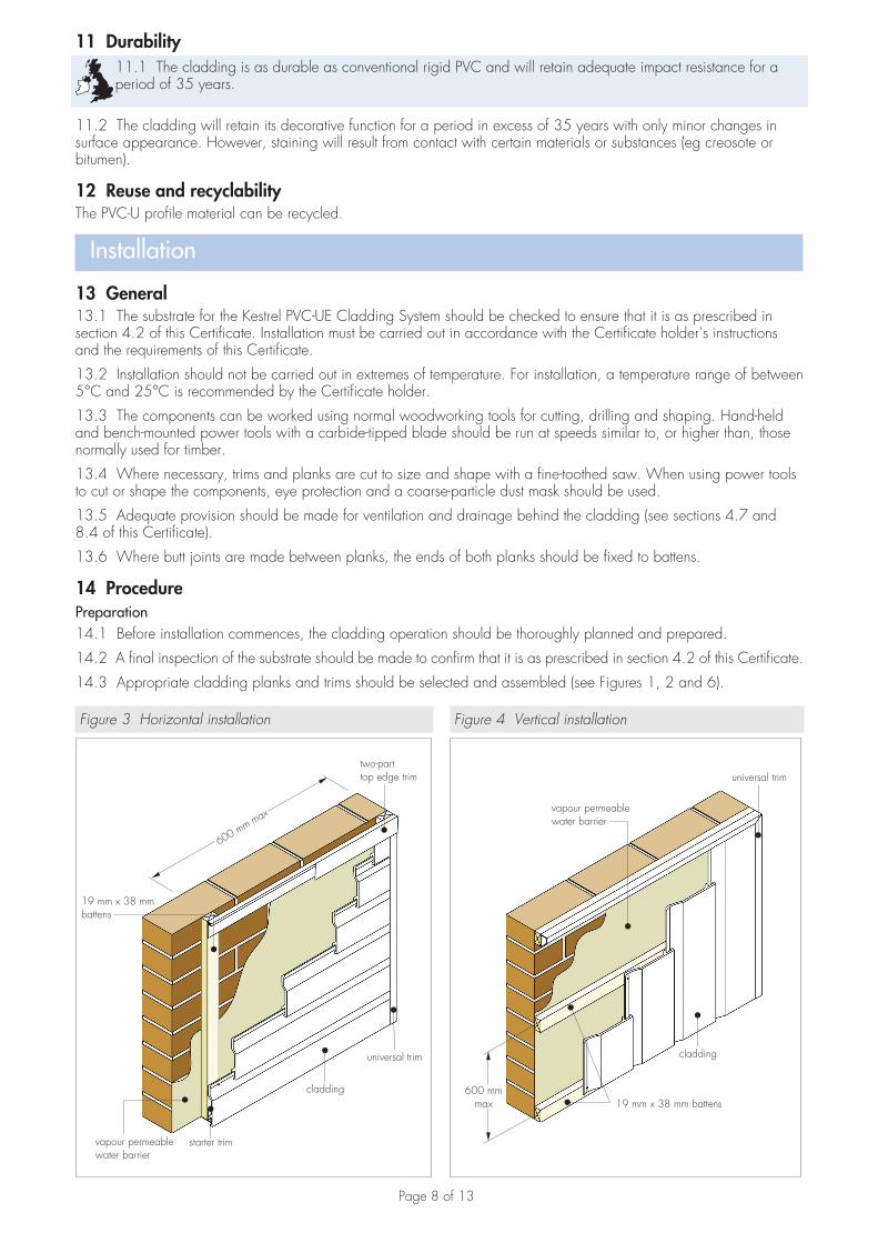
14.3 Appropriate cladding planks and trims should be selected and assembled (see Figures 1, 2 and 6).
Figure 3 Horizontal installation
starter trim
two-parttop edge trim
19 mm x 38 mmbattens
vapour permeablewater barrier
universal trim
cladding
600 mm max
Figure 4 Vertical installation
vapour permeablewater barrier
universal trim
cladding
19 mm x 38 mm battens600 mm
max
Page 9 of 13
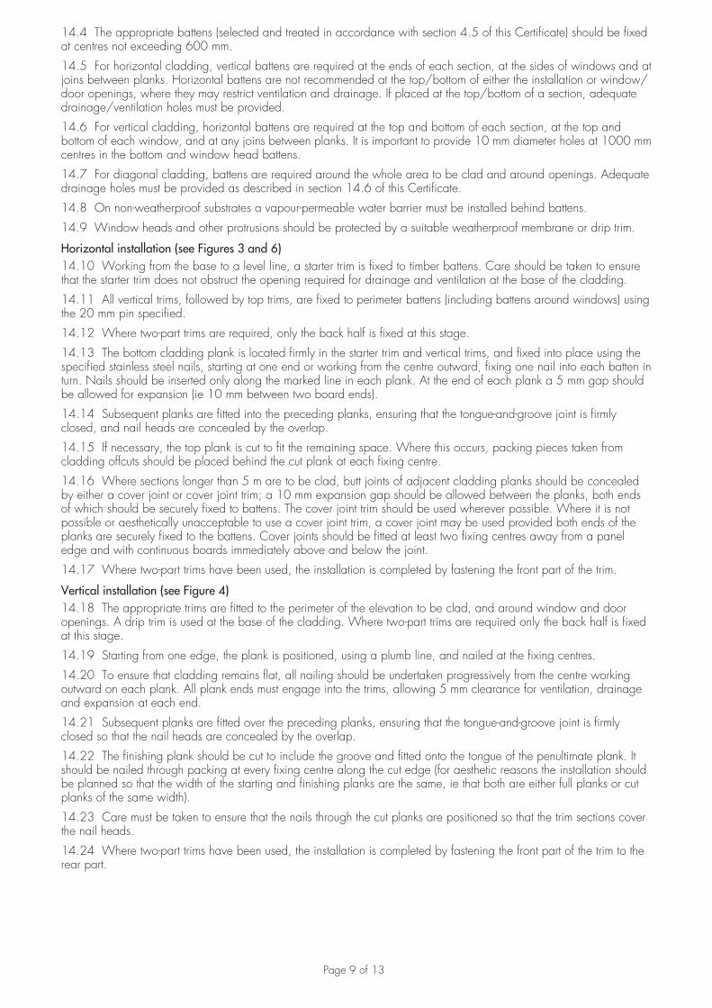
14.4 The appropriate battens (selected and treated in accordance with section 4.5 of this Certificate) should be fixed at centres not exceeding 600 mm.
14.5 For horizontal cladding, vertical battens are required at the ends of each section, at the sides of windows and at joins between planks. Horizontal battens are not recommended at the top/bottom of either the installation or window/door openings, where they may restrict ventilation and drainage. If placed at the top/bottom of a section, adequate drainage/ventilation holes must be provided.
14.6 For vertical cladding, horizontal battens are required at the top and bottom of each section, at the top and bottom of each window, and at any joins between planks. It is important to provide 10 mm diameter holes at 1000 mm centres in the bottom and window head battens.
14.7 For diagonal cladding, battens are required around the whole area to be clad and around openings. Adequate drainage holes must be provided as described in section 14.6 of this Certificate.
14.8 On non-weatherproof substrates a vapour-permeable water barrier must be installed behind battens.
14.9 Window heads and other protrusions should be protected by a suitable weatherproof membrane or drip trim.
Horizontal installation (see Figures 3 and 6)14.10 Working from the base to a level line, a starter trim is fixed to timber battens. Care should be taken to ensure that the starter trim does not obstruct the opening required for drainage and ventilation at the base of the cladding.
14.11 All vertical trims, followed by top trims, are fixed to perimeter battens (including battens around windows) using the 20 mm pin specified.
14.12 Where two-part trims are required, only the back half is fixed at this stage.
14.13 The bottom cladding plank is located firmly in the starter trim and vertical trims, and fixed into place using the specified stainless steel nails, starting at one end or working from the centre outward, fixing one nail into each batten in turn. Nails should be inserted only along the marked line in each plank. At the end of each plank a 5 mm gap should be allowed for expansion (ie 10 mm between two board ends).
14.14 Subsequent planks are fitted into the preceding planks, ensuring that the tongue-and-groove joint is firmly closed, and nail heads are concealed by the overlap.
14.15 If necessary, the top plank is cut to fit the remaining space. Where this occurs, packing pieces taken from cladding offcuts should be placed behind the cut plank at each fixing centre.
14.16 Where sections longer than 5 m are to be clad, butt joints of adjacent cladding planks should be concealed by either a cover joint or cover joint trim; a 10 mm expansion gap should be allowed between the planks, both ends of which should be securely fixed to battens. The cover joint trim should be used wherever possible. Where it is not possible or aesthetically unacceptable to use a cover joint trim, a cover joint may be used provided both ends of the planks are securely fixed to the battens. Cover joints should be fitted at least two fixing centres away from a panel edge and with continuous boards immediately above and below the joint.
14.17 Where two-part trims have been used, the installation is completed by fastening the front part of the trim.
Vertical installation (see Figure 4)14.18 The appropriate trims are fitted to the perimeter of the elevation to be clad, and around window and door openings. A drip trim is used at the base of the cladding. Where two-part trims are required only the back half is fixed at this stage.
14.19 Starting from one edge, the plank is positioned, using a plumb line, and nailed at the fixing centres.
14.20 To ensure that cladding remains flat, all nailing should be undertaken progressively from the centre working outward on each plank. All plank ends must engage into the trims, allowing 5 mm clearance for ventilation, drainage and expansion at each end.
14.21 Subsequent planks are fitted over the preceding planks, ensuring that the tongue-and-groove joint is firmly closed so that the nail heads are concealed by the overlap.
14.22 The finishing plank should be cut to include the groove and fitted onto the tongue of the penultimate plank. It should be nailed through packing at every fixing centre along the cut edge (for aesthetic reasons the installation should be planned so that the width of the starting and finishing planks are the same, ie that both are either full planks or cut planks of the same width).
14.23 Care must be taken to ensure that the nails through the cut planks are positioned so that the trim sections cover the nail heads.
14.24 Where two-part trims have been used, the installation is completed by fastening the front part of the trim to the rear part.
Page 10 of 13
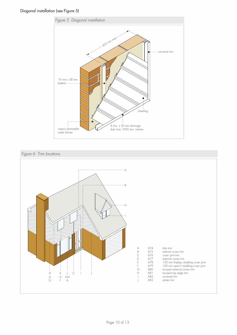
Diagonal installation (see Figure 5)
Figure 5 Diagonal installation
universal trim
19 mm x 38 mmbattens
vapour permeablewater barrier
cladding
425 mm max
4 mm x 30 mm drainageslots max 1000 mm centres
Figure 6 Trim locations
A 674 drip trimB 675 internal corner trimC 676 cover joint trimD 677 external corner trimE 678 150 mm shiplap cladding cover joint
G 680 two-part external corner trimH 681 two-part top edge trimI 682 universal trimJ 683 starter trim
F 679 100 mm open-V cladding cover joint
H
B
H
I
JICJandA
EorF
DorG
Page 11 of 13
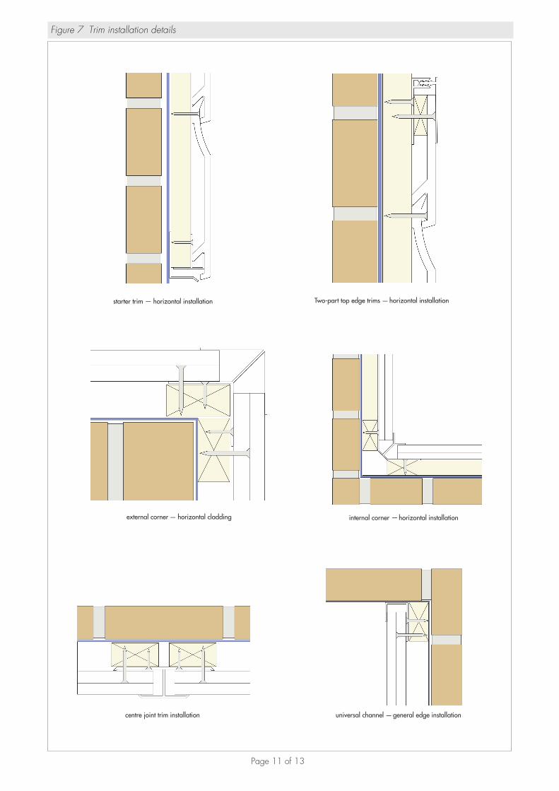
Figure 7 Trim installation details
starter trim horizontal installation— Two-part top edge trims horizontal installation
external corner horizontal cladding internal corner horizontal installation
centre joint trim installation universal channel general edge installation
—
——
—

Page 12 of 13
14.25 Horizontal battens are fixed to the substrate at maximum spacings of 425 mm to give a 600 mm distance between fixing centres on the diagonal cladding.
14.26 The appropriate trims are fixed to battens; use of two-part trims facilitates the installation. Only the back half of these trims is fixed at this stage.
14.27 The cladding planks are cut to size and fixed across the section at the required angle, starting with the smallest plank at the bottom corner.
14.28 To ensure that cladding remains flat, all nailing should be undertaken progressively from the centre working outward on each plank. All plank ends must engage into the trims, allowing 5 mm clearance for expansion at each end.
14.29 Subsequent planks are fitted into the preceding planks, ensuring that the tongue-and-groove joint is firmly closed so that the nail heads are concealed by the overlap.
14.30 Where two-part trims have been used, the installation is completed by fastening the front part of the trim.
Technical Investigations
15 TestsTests were carried out on planks and trims to determine:• Vicat softening temperature• density• weight per linear metre• ash content• tensile impact strength• Izod impact strength• impact resistance (cladding panel)• dimensional stability• tensile strength/elongation• modulus of elasticity• impact strength, dehydrochlorination (DHC) and appearance after UV ageing• impact strength, dehydrochlorination (DHC) and appearance after heat ageing• impact strength, dehydrochlorination (DHC) and appearance after watersoak• nail pull-through• heat reversion• acetone resistance• stress relief.
16 Investigations16.1 Permissible dynamic wind pressures were calculated from nail pull-through data.
16.2 The dimensions of cladding planks and trims were checked.
16.3 An examination was made of data relating to:• performance of the cladding to fire• colour stability.
16.4 The manufacturing process was examined, including the methods adopted for quality control, and details were obtained of the quality and composition of the materials used.
16.5 The practicability of installation was assessed.
BibliographyBS 5250 : 2011 Code of practice for control of condensation in buildingsBS EN 1991-1-4 : 2005 : 2010 Eurocode 1: Actions on structures — General actions — Wind actionsNA to BS EN 1991-1-4 : 2005 UK National Annex to Eurocode 1: Actions on structures — General actions — Wind actionsNA to BS EN 1995-1-1 : 2004 UK National Annex to Eurocode 5: Design of timber structures — General — Common rules and rules for buildings BS EN 1996-1-1 : 2005 Eurocode 6: Design of masonry structures — General rules for reinforced and unreinforced masonry structuresNA to BS EN 1996-1-1 : 2005 UK National Annex to Eurocode 6: Design of masonry structures — General rules for reinforced and unreinforced masonry structures
Page 13 of 13
BS EN 1996-3 : 2006 Eurocode 6: Design of masonry structures — Simplified calculation methods for unreinforced masonry structuresNA to BS EN 1996-3 : 2006 UK National Annex to Eurocode 6: Design of masonry structures — Simplified calculation methods for unreinforced masonry structuresBS EN 13245 : 2008 Plastics — Unplasticized poly(vinyl chloride) (PVC-U) profiles for building applications — PVC-U profiles and PVC-UE profiles for internal and external wall and ceiling finishesBS EN 13501-1 : 2007 : 2009 Fire classification of construction products and building elements — Classification using test data from reaction to fire testsBS EN ISO 6946 : 2007 Building components and building elements — Thermal resistance and thermal transmittance — Calculation methodBS EN ISO 9001 : 2008 Quality management systems — RequirementsBRE Report (BR 443 : 2006) Conventions for U-value calculations
Conditions of Certification
17 Conditions17.1 This Certificate:• relates only to the product/system that is named and described on the front page• is issued only to the company, firm, organisation or person named on the front page — no other company, firm,
organisation or person may hold or claim that this Certificate has been issued to them• is valid only within the UK• has to be read, considered and used as a whole document — it may be misleading and will be incomplete to be
selective• is copyright of the BBA• is subject to English Law.
17.2 Publications, documents, specifications, legislation, regulations, standards and the like referenced in this Certificate are those that were current and/or deemed relevant by the BBA at the date of issue or reissue of this Certificate.
17.3 This Certificate will remain valid for an unlimited period provided that the product/system and its manufacture and/or fabrication, including all related and relevant parts and processes thereof:• are maintained at or above the levels which have been assessed and found to be satisfactory by the BBA• continue to be checked as and when deemed appropriate by the BBA under arrangements that it will determine• are reviewed by the BBA as and when it considers appropriate.
17.4 The BBA has used due skill, care and diligence in preparing this Certificate, but no warranty is provided.
17.5 In issuing this Certificate, the BBA is not responsible and is excluded from any liability to any company, firm, organisation or person, for any matters arising directly or indirectly from:• the presence or absence of any patent, intellectual property or similar rights subsisting in the product/system or any
other product/system• the right of the Certificate holder to manufacture, supply, install, maintain or market the product/system• actual installations of the product/system, including their nature, design, methods, performance, workmanship and
maintenance• any works and constructions in which the product/system is installed, including their nature, design, methods,
performance, workmanship and maintenance• any loss or damage, including personal injury, howsoever caused by the product/system, including its manufacture,
supply, installation, use, maintenance and removal• any claims by the manufacturer relating to CE marking.
17.6 Any information relating to the manufacture, supply, installation, use, maintenance and removal of this product/system which is contained or referred to in this Certificate is the minimum required to be met when the product/system is manufactured, supplied, installed, used, maintained and removed. It does not purport in any way to restate the requirements of the Health and Safety at Work etc. Act 1974, or of any other statutory, common law or other duty which may exist at the date of issue or reissue of this Certificate; nor is conformity with such information to be taken as satisfying the requirements of the 1974 Act or of any statutory, common law or other duty of care.
British Board of Agrément tel: 01923 665300Bucknalls Lane fax: 01923 665301Watford [email protected] WD25 9BA www.bbacerts.co.uk©2015