Embed Size (px)
DESCRIPTION
Vetco Grey
Citation preview

imagination at work
Specialty Connectors & Pipe For land, platform, jackup, floater and deepwater applications

2 3
Pioneers of connector excellence
VetcoGray, a GE Oil & Gas business, is the pioneer in fast, simple and economical conductor and casing joint makeup for all drilling applications in both threaded and mechanical connectors.
VetcoGray’s threaded connectors are precision tool joints that simplify makeup of large diameter casing to save valuable rig time. Quick, accurate stabbing and virtual elimination of cross threading during initial engagement are ensured by the com-bination of the thread form and the tapered connector profile. A resilient seal in most threaded connectors ensures a high-pressure seal with a minimum of torque for increased opera-tional safety. For drilling applications that require non-rotation, reusable, mechanical connectors, the Squnch Joint® product line has become the choice of operators worldwide.
Regardless of whether they are threaded or mechanical, all VetcoGray conductor and casing connectors are designed and verified by extensive testing and analysis for compatibility with the strength and capacities of the pipe. The variety of sizes and field-proven styles available in our connector product line allows selection of the most suitable and economical connector for any type of application.
We offer a complete system approach through design, engineering analysis, and supply. Working together with our customers, we can establish requirements, such as applications, pipe sizes, coating, handling, circulation and installation; thus optimizing the complete drilling operation.
VetcoGray has an industry approved Quality Assurance pro-gram to ensure that connectors are manufactured to stringent design specifications. All connectors are machined on state-of-the-art numerically controlled equipment. Each connector is inspected for dimensional accuracy and reliability.
Specialty Connectors & Pipe
Table of contents
Specialty Connectors & Pipe . . . . . . . . . . . . . . . . . . 3
Complete joint service . . . . . . . . . . . . . . . . . . . . . . . . 4
Rental & running tools . . . . . . . . . . . . . . . . . . . . . . . . 5
Field service . . . . . . . . . . . . . . . . . . . . . . . . . . . . . . . . 5
Training . . . . . . . . . . . . . . . . . . . . . . . . . . . . . . . . . . . . 5
Technical and test data . . . . . . . . . . . . . . . . . . . . . . . . 6
Complete analytical services . . . . . . . . . . . . . . . . . . . 7
RapidLock™ (RL) connectors . . . . . . . . . . . . . . . . . . . 8
Quarter-turn makeup & connector reference chart . . . . . . . 9
Connector descriptions
RL-4TM connector . . . . . . . . . . . . . . . . . . . . . . . .10
RL-4C & 1C connectors . . . . . . . . . . . . . . . . . . . . . . . . 11
RL-4F & 1F connectors . . . . . . . . . . . . . . . . . . . . . . . . . 12
RL-4S & 1S connectors . . . . . . . . . . . . . . . . . . . . . . . . 13
RL-4H *superceded by the RL-2HCX . . . . . . . . . . . . . . . . . 14
RL-2HCX connector . . . . . . . . . . . . . . . . . . . . . . . . . . . . . 14
RL-3M connector . . . . . . . . . . . . . . . . . . . . . . . . . . . . . . . . 15
SR-20TM connector . . . . . . . . . . . . . . . . . . . . . . . . . . . . . . 16
ALT-2 Squnch Joint® . . . . . . . . . . . . . . . . . . . . . . . . . . 17
ALT-2HT Squnch Joint® . . . . . . . . . . . . . . . . . . . . . . . . 17
ALT-2HT HC Squnch Joint® . . . . . . . . . . . . . . . . . . . . . 17
ST-2 Squnch Joint® . . . . . . . . . . . . . . . . . . . . . . . . . . . 18
DMR & DMR-T connectors . . . . . . . . . . . . . . . . . . . . . . 19
TTR connector . . . . . . . . . . . . . . . . . . . . . . . . . . . . . . 20
SMAC connector . . . . . . . . . . . . . . . . . . . . . . . . . . 21
Connector standard specifications for pin & box sets
RL-4™ . . . . . . . . . . . . . . . . . . . . . . . . . . . . . . 22
RL-4 RB . . . . . . . . . . . . . . . . . . . . . . . . . . . . 22
RL-4C & RL-1C . . . . . . . . . . . . . . . . . . . . . . . . . . 22
RL-4F & RL-1F . . . . . . . . . . . . . . . . . . . . . . . . . . 23
RL-4S & RL-1S. . . . . . . . . . . . . . . . . . . . . . . . . . . . . . 23
RL-2HCX . . . . . . . . . . . . . . . . . . . . . . . . . . . 24
RL-3M . . . . . . . . . . . . . . . . . . . . . . . . . . . . . . 24
SR™-20 . . . . . . . . . . . . . . . . . . . . . . . . . . . . . 25
ALT-2 . . . . . . . . . . . . . . . . . . . . . . . . . . . . . . 26
ALT-2HT . . . . . . . . . . . . . . . . . . . . . . . . . . . 26
ST-2 . . . . . . . . . . . . . . . . . . . . . . . . . . . . . . . 26
ST-2RB . . . . . . . . . . . . . . . . . . . . . . . . . . . . . 26
ST-2HP . . . . . . . . . . . . . . . . . . . . . . . . . . . . . 27
ST-2HP RB . . . . . . . . . . . . . . . . . . . . . . . . . . 27
DMR . . . . . . . . . . . . . . . . . . . . . . . . . . . . . . . 28
DMR-T . . . . . . . . . . . . . . . . . . . . . . . . . . . . . 28
TTR . . . . . . . . . . . . . . . . . . . . . . . . . . . . . . . . 28
SMAC . . . . . . . . . . . . . . . . . . . . . . . . . . . . . . 28
Pipe body capacity tables
Grade B . . . . . . . . . . . . . . . . . . . . . . . . . . . . . 29
X-42 . . . . . . . . . . . . . . . . . . . . . . . . . . . . . . 29
X-52 . . . . . . . . . . . . . . . . . . . . . . . . . . . . . . 30
X-56 . . . . . . . . . . . . . . . . . . . . . . . . . . . . . 31
X-60 . . . . . . . . . . . . . . . . . . . . . . . . . . . . . . 32
X-65 . . . . . . . . . . . . . . . . . . . . . . . . . . . . . . . 32
X-80 . . . . . . . . . . . . . . . . . . . . . . . . . . . . . . . 33
Corporate overview . . . . . . . . . . . . . . . . . . . . . . 34
We supply field-proven connectors and accessories for every drilling area in the world.
Specialty Connectors & Pipe
VetcoGray connectors save time and money on the rig. For example, running time for the 20” RL-4S can average less than 4 minutes per joint from pick up to fill up, versus 12 to 14 minutes per joint for 20” buttress.
32

4 5
Rental and running toolsComplete joint service
Cost saving advantages
The time and cost saving advantages of large diameter con-ductor and casing connectors are enhanced by the availability of the worldwide VetcoGray Complete Joint Service. Eliminat-ing the need for field welding and inspection, connectors are welded to customer specified pipe prior to shipment. Welding and inspection processes are performed under ideal condi-tions and full documentation on pipe material and weld quality is provided as required.
Our expertise in materials, welding and inspection ensures that the material properties of the connector, weld and pipe are maintained throughout the manufacturing process of a complete joint.
Thorough control and documentation of the welding and inspection processes assure traceability and verification of the material properties and provide consistent, demonstrable quality.
VetcoGray provides heavy-duty protectors that prevent dam-age to the connectors from the time they leave the plant until they are used on the rig floor.
Prompt delivery of tubulars and connectors is assured from our worldwide manufacturing facilities, such as those in Texas, Scotland, Singapore and Brazil.
Rental and running tools
VetcoGray has rental and running tools, including drive subs, elevators, circulating heads, bull tongs and crossover subs available to rent for all tubular products.
• Drivesubstointerfacewithhydraulicandpneumatic hammers for a variety of VetcoGray connectors
• Heavydutyelevatorsforhandling30”pipeforALT-2andST-2 Squnch Joint connectors and RL-4’s
• CirculatingheadstocrossoverfromVetcoGrayconnectorsto 2” line pipe or Weco Union connections to permit washout operations after cementing
• Adjustable,chaintypebulltongsforeasymakeupof threaded connections
• CrossoversubstoconvertVetcoGrayconnectorstobuttressand 8-RD thread forms
Field service
Field service technicians are on call twenty-four hours a day, 365 days a year, at all our locations worldwide. Repair and testing services are available, in addition to our standard installation service. VetcoGray offers services that include maintenance programs, field inspection of existing equipment and engineering backup for unique situations.
Training
We offer complete, practical, up to date product and systems technical training courses in the design configuration, instal-lation and operation of drilling equipment for jackup, platform, floater and deepwater applications. Courses feature the latest methods for increasing operational efficiency, reliability and safety in basic product lines.
Welders are trained and certified to ensure the integrity of the materials.

6 7
Dedication to quality
When VetcoGray systems are combined in projects, they meet customer requirements in the most dependable, cost effective manner. Our expert engineering staff designs, develops, and tests new products to meet the ever changing needs of the industry while supporting a full line of standard proven products already tested and used extensively throughout the world.
Engineering, testing and analysis utilize modern engineer-ing tools, such as Pro/Engineer, CAD, finite element analysis, internally-developed design computer programs, metallurgical laboratories, elastomer laboratories, as well as a completely outfitted Research & Engineering laboratory for functional and
load testing. Load testing equipment includes tension, com-pression and bending test fixtures, bending fatigue test fixtures and a variety of pressure testing fixtures. Functional testing includes makeup, breakout, and stabbing tests. The results of all these tests are compared with the analysis to establish rated capacities. Test data is available on request.
All VetcoGray conductor and casing connectors are subjected to comprehensive functional and full-scale structural test pro-grams to prove the functionality of each connector and verify the analytical design techniques used.
Design and strength assessment
Since 1980, VetcoGray has been offering complete analytical services to assist customers in the design and strength assessment of conductors, risers, and tieback strings for specific applications. Capabilities include analyses of riser or conductor static strength and pile driving response as well as fatigue and fracture mechanics assessment. Predictive models used for these applications can include intermediate support points, gaps at the support points, intermediate strings, and soil stiffness.
We use the latest analysis techniques available to the industry. Some of the software programs used are ANSYS1 for linear elastic Finite Element Analysis (FEA), STARIS2 for marine drilling and production risers analysis, PATRAN3 for 3-D finite element modeling, and ABAQUS4 for analysis of large deflection and non-linear material problems. Various other software programs and hardware are available to support complete project execution and reporting.
Each riser or conductor system and application is significantly different and has its own particular analysis requirements. However, common to all applications is the strength and stability
check on the outer string. In all cases, the outer string plus at least one of the inner strings are modeled on ANSYS. From the FEA, the maximum bending moment and stress at any loca-tion may be obtained.
Fatigue or fracture mechanics analysis is generally done only for long-term applications, such as platform wells. The fatigue life of a system can be calculated using classical stress or strain life techniques. Fatigue life can also be assessed using fracture mechanics methods and NASCRAC – the industry accepted coding. Total damage or life for any point in the structure can be obtained for conductor, welds and connectors.
A system can be assessed for effects of a pile-driving hammer on a conductor. This analysis calculates the peak pipe wall stress during driving to determine if the conductor material strength is acceptable.
By working closely with design, manufacturing and field service, VetcoGray analysts are able to provide practical results that assist customers in selecting structurally adequate and cost effective equipment designs.
VetcoGray’s R&E testing yard: bending capacity testing machines with tubulars.
Our experienced, expert engineers can perform complete analysis on all the components that go into the various riser systems to provide the strength and fatigue related data needed to understand the structural behavior of different system configurations and applications.
Complete analytical servicesTechnical and test data
von Mises Stress contour plot of RL-4™ connector subjected to maximum operating tensile load.
1 ANSYS is a registered trademark of Ansys Inc.2 STARIS is a registered trademark of Starmark Offshore.3 PATRAN is a registered trademark of The MacNeal-Schwendler Corporation.4 ABAQUS is a registered trademark of Hibbitt, Karlsson and Sorensen, Inc.

8 9
Unique self-locking connectors
The RapidLock thread form is a unique, self locking connector that creates a pre-load force between the pin and the box. The RapidLock connector has a helix angle less than the critical coefficient of friction in a ratio similar to that of 4-1/2” API IF drill pipe. Testing has confirmed the application of pulsed torque to 97% of the breakout torque value with no back off. The positive stop on the connector and the five degree back-rake angle of the thread form combine to reduce any belling tendency. The load flanks contact only after the connector is fully stabbed, and since the minimum rotation for makeup reduces metal-to-metal friction, the potential for thread galling is greatly reduced.
For driven or tieback applications, all RL-4 conductor connectors as well as RL-4S casing connectors can be equipped with a secondary locking system where four integral locking tabs
are machined on the box and four slots in the pin. This pro-vides added protection against connector back off without the use of strapping or thread-locking compound. The RL-4 style connectors feature four-start threads that provide makeup with only 1/4 to 1/2 turn of the suspended pipe. The RL-1 style connectors have a single start thread that makes-up in 1-1/3 to 2-1/3 turns.
After makeup, the box tab is cut to fit with a portable, hand held locking tool that shears the tab and forces it into the corresponding slot on the pin. To release, the anti-rotation tab can be pried out, cut out with the releasing head on the locking tool or cut with an acetylene torch. As an alternative, additional torque above that of the makeup torque, can be applied to overcome the locking tabs. The connector can then be released and reused.
Quarter-turn makeup
RL-4 anti-rotation tab and hand-held locking tool
Quarter-turn makeup & Connector reference chartRapidLock™ RL connectors
RL-4 pin and box
Four separate, identi-cal interlocking threads start 90 degrees apart at the beginning of the thread form and engage simultaneously.
1
Initial stab
Self-aligning dual stab guides on the pin and box bring the connector into full alignment before the threads engage, pre-venting cross threading.
2
Self-alignment
Easy stabbing is assured by the geometry of the connectors, which allows over 95% of the pin to be swallowed by the box before rotation. Weight is slacked off before rotation.
3
Fully stabbed before rotation
One quarter-turn at the recommended makeup torque fully shoulders and pre-loads the con-nection and energizes the seal. Positive makeup is visually verified.
4
After quarter- turn makeup
* Connectors may be used in applications other than noted.
Connector Reference Chart
LAND PLATFORM JACKUP FLOATER DEEPWATER
RL-4 X X X X
RL-4RB X X X X
RL-4C X X X X
RL-1C X X X X
RL-4F X X X X
RL-1F X X X X
RL-4S X X X X X
RL-1S X X X X
RL-2HCXB X X X X
RL-3M X X X X
SR-20 X X
ALT-2 X X X
ALT-2HT X X
ST-2 X X X
ST-2RB X X X
ST-2HP X X X
ST-2HP RB X X X
DMR X
TTR X X X
SMAC X X

10 11
Pre-loaded, compact connectorPre-loaded, high strength connector
RL-4™ connector
The rigid, pre-loaded RL-4 high strength connector has been the overwhelming choice of Platform and Floater operators since its introduction to the drilling industry in the early 1980’s. In Jackup applications, the RL-4 is very effective as the large-diameter connector, recommended for use with long conductor strings or in areas with high currents. The RL-4 connector features four-start threads, which provide makeup with only 1/4 to 1/2 turn of the suspended pipe. The RL-4 is ideal for deepwater, multi-slot applications.
RL-4 conductor connectors are equipped with a secondary locking system where four integral locking tabs are machined on the box to align with four slots on the pin. This integral anti-rotation feature provides added protection against connector back-off without the use of weld-on straps or thread- locking compounds. Engagement of the anti-rotation feature is particularly valuable in driving, tieback, high current or deepwater applications.
Standard specifications for pin and box sets, see page 22. Pipe body capacities, see pages 29-33.
RL-4C & RL-1C connectors
The RL-4C is recommended to save valuable running time for non-driven casing strings. This pre-loaded, light, compact, economical connector is compatible with the strength and capacity of the pipe and is for use in Land, Platform, Jackup and Floater applications. The RL-4C connector features four-start threads, which provide makeup with only 1/4 to 1/2 turn of the suspended pipe. The RL-1C single start thread connection makes up in 1-1/3 to 2-1/3 turns.
Standard specifications for pin and box sets, see page 22. Pipe body capacities, see pages 29-33.
RL-4™ connector
Positive stopload shoulder
(Drive shoulder)
Stab guide
O-ring seal
Self-aligningthread profile
Self-lockingthread form
Anti-rotationfeature
Stab guide
Elevator shoulder
RL-4CTM connector
Makeup indicator
Stab guide
Self-lockingthread profile
Self-aligningthread form
O-ring seal
Stab guide
Positive stopload shoulder
Elevator shoulder
Features & benefits
• Fast1/4turnmakeup
• Self-locking,four-startthreadform
• Self-aligningthreadprofiletoprevent cross threading
• Highstabanglewithdualstabguides
• Pre-loadedforstrengthandrigidity
• Positivestoploadshoulder
• Availablein28”-42”diameters
• Driveable,releasable,reusable
• Integralanti-rotationfeature
• Excellentinharshenvironmentalconditions
• Availableinreducedboreconfiguration
• Accessthroughrestrictedareas
• Negativebackrakeangleonthreadreduces belling tendency
• Eliminatesneedforpowertongsand casing crews
• DualO-ringversionavailablefor thread protections
Features & benefits
• Fast1/4turnmakeup
• Patented,self-locking,four-startthreadform
• Self-aligningthreadprofiletopreventcrossthreading
• Highstabanglewithdualstabguides
• Pre-loadedforstrengthandrigidity
• Positivestoploadshoulder
• Visualverificationmakeupindicator
• Availablein16”-20”diameter
• 16”passesthroughastandardsubsea wellhead housing
• 20”passesthrougha21-1/4”annularBOPor diverter and accepts standard mudline equipment
• Negativebackrakeangleonthreadreduces belling tendency
• Eliminatesneedforpowertongsandcasingcrews

12 13
Pre-loaded, high strength connectorPre-loaded, high strength connector
RL-4F & RL-1F connectors
The RL-4F pre-loaded, high strength connector has a flush outside diameter for jetting, driving and drilling in Platform, Jackup, Floater and Deepwater applications. The RL-4F connector features four-start threads, which provide makeup with only 1/4 to 1/2 turn of the suspended pipe. The RL-1F single start thread connection makes up in one to two turns. An anti-rotation key is installed at the pin and box interface to provide additional torque resistance.
Standard specifications for pin and box sets, see page 23. Pipe body capacities, see pages 29-33.
RL-4S & RL-1S connectors
The RL-4S pre-loaded, high strength connector has been field-proven in many different applications, environments and drilling programs for Land, Platform, Jackup and Floater applications, including highly deviated deep wells. The RL-4S connector features four-start threads, which provide makeup with only 1/4 to 1/2 turn of the suspended pipe. The RL-1S single start thread connection makes up in 1-1/3 to 2-1/3 turns.
RL-4S casing connectors are equipped with a secondary locking system where four integral locking tabs are machined on the box to align with four slots on the pin. This integral anti-rotation feature provides added protection against connector back off without the use of weld-on straps or thread-locking compounds. Activation of the anti-rotation feature is recommended in driving, tieback, high current, or deepwater applications.
Standard specifications for pin and box sets, see page 23. Pipe body capacities, see pages 29-33.
RL-4FTM connector
Anti-rotation key
Positive stopload shoulder
(drive shoulder)
Stab guide
Self-lockingthread profile
Self-aligningthread form
O-ring seal
Stab guide
RL-4STM connector
Makeup indicator
Stab guide
Anti-rotationfeature (slot/tab)
Self-aligningthread profile
Self-lockingthread form
O-ring seal
Stab guide
Positive stopload shoulder
Elevatorshoulder
Anti-rotation keystandard on RL-4F style
connectors
Features & benefits
• Fast1/4turnmakeup
• Patented,self-locking,four-startthreadform
• Self-aligningthreadprofiletopreventcrossthreading
• Highstabanglewithdualstabguides
• Pre-loadedforstrengthandrigidity
• Positivestoploadshoulder
• Flushshoulderonpinprovidesverificationof proper makeup
• Availablein16”-26”diameters
• Driveable,releasable,reusable
• Highstrengthanti-rotationtabs
• 20”acceptsstandardmudlineequipment
• Negativebackrakeangleonthreadreduces belling tendency
• Eliminatesneedforpowertongsandcasingcrews
• DualO-ringversionavailableforthreadprotection
Features & benefits
• Fast1/4turnmakeup
• Patented,self-locking,four-start thread form
• Self-aligningthreadprofiletoprevent cross threading
• Highbendingcapacity
• Pre-loadedforstrengthandrigidity
• Highstrengthanti-rotationkeys
• Availablein24”-36”diameters
• FlushODforjetting,drivinganddrilling through restricted areas

14 15
Metal-to-metal seal, high strength connectorPre-loaded, high strength connector
RL-2HCX connector
The RL-2HCX pre-loaded, high strength connectors are the strongest connectors available for DDCV, TLP and Deepwa-ter Drillships requiring high bending and fatigue capabilities, and are also for use in Platform and Jackup applications. The RL-2HCX connector feature two-start threads, which provide makeup of less than 1 turn of the suspended pipe.
The RL-2HCX connector shoulder out on the OD at the pin and box interface and have a secondary shoulder on the inside. Anti-rotation keys are installed at the pin and box interface to provide additional torque resistance.
Standard specifications for pin and box sets, see page 24. Pipe body capacities, see pages 29-33.
RL-3M connector
The RL-3M pre-loaded, high strength connector has a Primary metal-to-metal seal at the pin nose based on the proven RL-P design with an O-ring backup. A dual O-ring version is avail-able for full thread isolation. The RL-3M connector features three-start threads, which provide makeup with only 9/16 to 7/8 turn of the suspended pipe.
These high strength connectors are self-aligning with stab guides that protect the metal-to-metal seal during makeup. The RL-3M connectors shoulder out on the OD at the pin and box interface. Anti-rotation keys are installed at the pin and box interface to provide additional torque resistance.
Standard specifications for pin and box sets, see page 24. Pipe body capacities, see pages 29-33.
RL-2HCX connector
High-torque anti-rotation key
Positive stopload shoulder
Stab guide
O-ring seal
Improved high-capacity thread form
Optionallip seal
Elevator shoulder
RL-3M connector
High-torque anti-rotation key
Positive stopload shoulder
High-integrity metal to metal seal
Stab guide
Optional secondaryo-ring seal
Improved high-capacity thread form
O-ring seal
Elevator shoulder
Anti-rotation keystandard on RL-2HCX style
connectors
Anti-rotation keystandard on RL-3M style
connectors
Features & benefits
• Fast<1turnmakeup
• Self-aligningthreadprofiletoprevent cross threading
• Highstabanglewithdualstabguides
• Pre-loadedforstrengthandrigidityandgood fatigue characteristics
• Positivestoploadshoulder
• Availablein36”,otherdiametersavailable upon request
• Driveable,releasable,reusable
• Excellentinharshenvironmentalconditions
• Negativeback-rakeangleonthreadreduces belling tendency
• Dualsealoptionforfullthreadisolation
• Lipsealeliminatesbleedportrequirementindual seal configuration
• Largeradiusfilletsandstressreliefgroovesfor improved fatigue life
Features & benefits
• Primarymetal-to-metalsealatpinnosebasedon proven RL-P design
• Self-aligningthreadprofiletopreventcrossthreading
• Pre-loadedforstrengthandrigidityandhigh fatigue characteristics
• Positivestoploadshoulder
• Availablein20”&22”diameters
• Driveable,releasable,reusable
• Fast9/16turnmakeup
• Excellentfordeepwaterandharshenvironments
• Negativebackrakeangleonthreadreduces belling tendency
• Eliminatesneedforpowertongsandcasingcrews
• DualO-ringversionavailableforfullthreadisolation

16 17
Pre-loaded, high strength connector
SR-20 connector
The pre-loaded, high strength SR-20 is especially designed for long term fatigue applications on Platforms and Jackups, the central element of a platform conductor system that is simple, economical and efficient.
Standard specifications for pin and box sets, see page 25. Pipe body capacities, see pages 29-33.
SR-20 connector
Clamp groove
Load shoulder
Metal-to-metal seal
O-ring seal
Centralizingthread profile
Pressureinjection port
O-ring seal
Metal-to-metal seal
Clamp grooveAlignment key standard on
SR-20 style connectors
Features & benefits
• Patentedtwo-startinterference-fitthreadform
• Highradialpre-loadforstrength,rigidityandlongtermfatigue life
• Dualmetal-to-metalsealingforcorrosionprotection
• Highstabangle
• Availablein20”-32”diameters
• Fast,snap-togethermakeupinlessthanonesecondusingspecial clamp tool; One turn release
• Highdrivingefficiency,releasable,reusable
Weight set connector
ALT-2/ALT-2HT/ALT-2HT HC Squnch Joint®
For over 25 years, Squnch Joints have been used in non-rotation, weight-set applications on Floaters, Jackups and Platforms. When higher bending capacity is needed in a non-rotating connection, the ALT-2 can be used for connecting pipe joints up to 42”.
The ALT-2HT is designed for use in deepwater dynamically positioned applications where high torque resistance may be needed to compensate for rig movement and rotation.
Another option is the ALT-2HT HC 110ksi, which was developed for high bending loads where unconsolidated seabed condi-tions exist.
Standard specifications for pin and box sets, see page 26. Pipe body capacities, see pages 29-33.
ALT-2HT connector
Shoulder
Stab guide
O-ring seal
Lock ring
Releasingscrew hole
Anti-rotationkey
Elevator shoulder
ALT-2 connector
Shoulder
Stab guide
O-ring seal
Lock ring
Releasingscrew holes
Anti-rotationpin/slot
Anti-rotationvisual indicator
Elevator shoulder
Features & benefits
• Heavy-duty
• Compatiblewithlargerwallthicknessandhigherstrengthconductor pipe
• Availablein20”-42”diameters
• Wideshoulderfordrivingapplications
• Anti-rotationpinandslotpreventrotationaftermakeup
• 20”utilizedwith18-3/4”housingasahighpressure extension for high bending loads
• AvailableinHighTorqueresistantconfiguration.
• Fouranti-rotationkeysforhightorqueresistance
• Availablein20”-36”diameters

18 19
Weight set connector
ST-2 Squnch Joint®
Squnch Joints have been used for over 25 years in non-rotation, non-driving, weight-set applications for Floaters, Jackups and Platforms. Recommended for non-rotation makeup on con-ductor strings that are run into a pre-drilled hole and cemented into place.
The ST-2 is a reusable, mechanical release connector that has been field-proven worldwide. The ST-2 is available with a reduced bore configuration for passage through restricted areas, as well as a high performance option for use in increased load applications.
Standard specifications for pin and box sets, see pages 26-27. Pipe body capacities, see pages 29-33.
ST-2 connector
Releasingscrew holes
Lock ring
Stab guide
O-ring seal
Anti-rotationpin/slot
Anti-rotationvisual indicator
Elevator shoulder
Features & benefits
Standard duty
• Fastreleasecapability
• Availablein30”diameter
• Reusable
• Weight-setforeasystabbingoperation.Norotation required
• Anti-rotationpinandslotpreventrotationaftermakeup
• Inmostcases,thepinandboxconnectorsare interchangeable, regardless of wall thickness
• Availableinreducedboreconfiguration.Accessthrough restricted areas
• Availableinhighperformanceoption.Increasedload applications
Remote release connector
DMR connector
The DMR is a driveable, mudline, releasable connector specifi-cally designed for Jackup drilling applications where diverless release of the large diameter conductor is required. When the DMR is remotely released, a box connection is left on the well. At a later date, the well can be tied back using the DMR-T pin to re-establish the connection.
Standard specifications for pin and box sets, see page 28. Pipe body capacities, see pages 29-33.
DMR connector
Debris shield
Locking lug
Releasingscrew holes
O-ring seal
Lock ringgroove profile
Load shoulder
DMR-T pin fortieback applications
Integral debrisshield
Locking lugs (4)
Shear pin slots (4)
Shipping boltreceptacle
Shear pinreceptacle
Locking lugin final position
DMRbox
DMRpin
Features & benefits
• Simple,reliable,lowtorquerelease
• Pre-determineddisconnectpoint
• Positivelockingofconnectionduringjointhandling and driving
• Doesnottightenduringdriving
• Noseparatemechanismsorcablesrequiredtorelease
• Deepstab–ampledrivingreboundallowancepreventsdamage to connector during driving
• Availablein26”-30”diameters
• EasytiebackusingDMR-Tpin
• Pinreusableonacontinuedwelltowellprogram
20 21
TTR connector
Positive stopload shoulder
(drive shoulder)
Stab guide
Stab guide
O-ring seal
Self-aligningthread profile
Self-lockingthread form
Elevator shoulder
Remote release connector
TTR connector
The pre-loaded, remote release TTR connector is recommended to save valuable running time for non-driven casing strings in Land, Platform, and Jackup applications. This light, compact, and economical connector is compatible with the strength and capacity of the pipe. The TTR features the same four-start threads as the RL-4, which provide makeup with only 1/4 to 1/2 turn of the suspended pipe.
Standard specifications for pin and box sets, see page 28. Pipe body capacities, see pages 29-33.
Features & benefits
• Simplifiesrecoveryoperations
• Eliminatestheneedforpipecutting
• EquivalentinstrengthtoanRL-4
• Availablein30”diameters
• Left-handthreadforright-handrelease
• Pre-loadedforhigherfatiguelife
• DualO-ringsprotectthreadsfromcorrosion
• Integralsecondarylockingdeviceavailablefor driving applications
Remote release connector
SMAC connector
The hydraulically released Sub-Mudline Abandonment Con-nector (SMAC) operates in standard applications for use in approximately 300 to 400m water depth and deep water ap-plications to 1000m water depth.
The SMAC separates 30” x 1-1/2” wall X 56” conductor pipe ap-proximately 3-5m below mud line.
SMAC connector can withstand minimum 2,000,000 ft lbs bending x 500,000 lbs tension.
Safely supports conductor running operation.
Loss of hydraulic lines shall not cause premature disconnect.
Standard specifications for pin and box sets, see page 28. Pipe body capacities, see pages 29-33.
SMAC connector
SMAC pin
Visual indicator
View port
Piston
Latch ring
SMAC box
Features & benefits
• Straightstabmechanicalmakeup(noHydraulicsrequired)
• Remotehydraulicrelease
• Canbemadeuphorizontallyorverticallywith visual confirmation
• Hydrauliclinesareshroudedinside30”wellheadextension
• Norotationrequiredtodisconnectbelowmudline
• Noexteriormechanismsbelowmudline
• Wellheadextensionwithreusablepincoatedtopreventadhesion of cement
• Canbemaintainedonlocationforre-use
• Optionalanti-rotation

22 23
Connector standard specifications
Pin and box sets
(1) Yield and ultimate capacities are calculated based on minimum material properties, under single load conditions, and are based on test and/or analysis.
(2) All ratings include weld preps.NOTE: Other wall size and application connectors available.
Nominal O.D.
Wall Thickness
Material Yield
StrengthConnector
O.D.Connector
I.D.Length
Made UpConnector
Weight
Tensile Yield
Capacity (1) (2)
Bending Yield
Capacity (1) (2)
Internal Yield
Pressure (1) (2)
Ultimate Tensile
Capacity (2)
Ultimate Bending Capacity
(2)
in mm in mm ksi in mm in mm in mm lb N kips MN kip-ft kN.m psi MPa kips MN kip-ft kN.m
30 762.0 1.000 25.4 70 30.80 782.3 26.50 673.1 12.88 327.2 623 2771 4600 20.46 2800 3796 4670 32.2 8100 36.03 5190 7037
30 762.0 1.000 25.4 95 30.80 782.3 26.50 673.1 12.88 327.2 623 2771 6240 27.76 3800 5152 5000 34.5 10900 48.48 7280 9870
30 762.0 1.500 38.1 95 30.80 782.3 26.00 660.4 12.88 327.2 643 2860 6240 27.76 3800 5152 5000 34.5 10900 48.48 7280 9870
36 914.4 1.000 25.4 95 36.81 935.0 31.75 806.5 17.00 431.8 1048 4662 10000 44.48 5250 7118 3900 26.9 13500 60.05 14070 19076
36 914.4 1.500 38.1 95 36.81 935.0 31.75 806.5 17.00 431.8 1099 4888 10000 44.48 5250 7118 3900 26.9 13500 60.05 14070 19076
RL-4RB (Reduced Bore)
Nominal O.D.
Wall Thickness
Material Yield
StrengthConnector
O.D.Connector
I.D.Length
Made UpConnector
Weight
Tensile Yield
Capacity (1) (2)
Bending Yield
Capacity (1) (2)
Internal Yield
Pressure (1) (2)
Ultimate Tensile
Capacity (2)
Ultimate Bending Capacity
(2)
in mm in mm ksi in mm in mm in mm lb N kips MN kip-ft kN.m psi MPa kips MN kip-ft kN.m
*16 406.4 0.438 11.1 60 17.12 434.8 14.84 376.9 7.64 194.1 106 471 1066 4.74 405 549 3500 24.1 1650 7.34 770 1044
16 406.4 0.500 12.7 60 17.12 434.8 14.87 377.7 7.64 194.1 107 476 1066 4.74 413 560 4000 27.6 1800 8.01 770 1044
18-5/8 473.1 0.438 11.1 60 19.75 501.7 17.65 448.3 7.64 194.1 117 520 1004 4.47 555 752 3000 20.7 1925 8.56 900 1220
18-5/8 473.1 0.500 12.7 60 19.75 501.7 17.59 446.8 7.64 194.1 120 534 1188 5.28 628 851 3400 23.4 2120 9.43 900 1220
20 508.0 0.438 11.1 60 21.00 533.4 18.75 476.3 7.64 194.1 125 556 1340 5.96 644 873 2750 19.0 2070 9.21 1005 1363
20 508.0 0.500 12.7 60 21.00 533.4 18.75 476.3 7.64 194.1 130 578 1340 5.96 728 987 3150 21.7 2250 10.01 1005 1363
20 508.0 0.625 15.9 60 21.00 533.4 18.63 473.2 7.64 194.1 134 596 1464 6.51 802 1087 3600 24.8 2250 10.01 1005 1363
RL-4C
Nominal O.D.
Wall Thickness
Material Yield
StrengthConnector
O.D.Connector
I.D.Length
Made UpConnector
Weight
Tensile Yield
Capacity (1) (2)
Bending Yield
Capacity (1) (2)
Internal Yield
Pressure (1) (2)
Ultimate Tensile
Capacity (2)
Ultimate Bending Capacity
(2)
in mm in mm ksi in mm in mm in mm lb N lb MN kip-ft kN.m psi MPa kips MN kip-ft kN.m
20 508.0 0.438 11.1 60 21.00 533.4 18.75 476.3 7.64 194.1 125 556 1340 5.96 644 873 2750 19.0 2070 9.21 1005 1363
20 508.0 0.500 12.7 60 21.00 533.4 18.75 476.3 7.64 194.1 130 578 1340 5.96 728 987 3150 21.7 2250 10.01 1005 1363
20 508.0 0.625 15.9 60 21.00 533.4 18.63 473.2 7.64 194.1 134 596 1464 6.51 802 1087 3600 24.8 2250 10.01 1005 1363
RL-1C
Nominal O.D.
Wall Thickness
Material Yield
StrengthConnector
O.D.Connector
I.D.Length
Made UpConnector
Weight
Tensile Yield
Capacity (1) (2)
Bending Yield
Capacity (1) (2)
Internal Yield
Pressure (1) (2)
Ultimate Tensile
Capacity (2)
Ultimate Bending Capacity
(2)
in mm in mm ksi in mm in mm in mm lb N kips MN kip-ft kN.m psi MPa kips MN kip-ft kN.m
*22 558.8 0.625 15.9 110 23.88 606.6 19.00 482.6 18.00 457.2 670 2980 4617 20.54 2000 2712 5470 37.7 – – – –
*22 558.8 0.812 20.6 110 23.88 606.6 19.00 482.6 18.00 457.2 685 3047 5625 25.02 2531 3432 7100 49.0 – – – –
*22 558.8 1.000 25.4 110 23.88 606.6 18.50 469.9 18.00 457.2 702 3122 5625 25.02 2578 3495 8700 60.0 – – – –
*28 711.2 0.625 15.9 70 29.88 759.0 26.12 663.4 20.75 527.1 517 2300 3210 14.28 1550 2101 2600 17.9 – – – –
*28 711.2 0.750 19.1 70 29.88 759.0 26.12 663.4 20.75 527.1 522 2322 3210 14.28 1550 2101 2600 17.9 – – – –
*30 762.0 0.625 15.9 70 31.63 803.4 27.88 708.2 13.36 339.3 565 2513 4040 17.97 2420 3281 2915 20.1 6150 27.36 2835 3844
*30 762.0 0.750 19.1 70 31.63 803.4 27.88 708.2 13.36 339.3 565 2513 4600 20.46 2800 3796 3500 24.1 6150 27.36 3360 4555
*30 762.0 1.000 25.4 70 31.63 803.4 27.50 698.5 13.36 339.3 625 2780 4600 20.46 2800 3796 4670 32.2 8100 36.03 4600 6237
*30 762.0 1.000 25.4 95 31.63 803.4 27.50 698.5 13.36 339.3 625 2780 6240 27.76 3800 5152 5000 34.5 10900 48.48 6450 8745
*30 762.0 1.250 31.8 95 31.63 803.4 26.97 685.0 13.36 339.3 705 3136 6240 27.76 3800 5152 5000 34.5 10900 48.8 6450 8745
*30 762.0 1.500 38.1 95 31.63 803.4 26.97 685.0 13.36 339.3 725 3225 6240 27.76 3800 5152 5000 34.5 10900 48.8 6450 8745
RL-4™
*RL-4 SLIMLINE
Connector standard specifications
Pin and box sets
(1) Yield and ultimate capacities are calculated based on minimum material properties, under single load conditions, and are based on test and/or analysis.
(2) All ratings include weld preps.NOTE: Other wall size and application connectors available.
Nominal O.D.
Wall Thickness
Material Yield
StrengthConnector
O.D.Connector
I.D.Length
Made UpConnector
Weight
Tensile Yield
Capacity (1) (2)
Bending Yield
Capacity (1) (2)
Internal Yield
Pressure (1) (2)
in mm in mm ksi in mm in mm in mm lb N kips MN kip-ft kN.m psi MPa
24 609.6 0.750 19.1 70 24.02 610.0 20.13 511.2 16.38 416.1 535 2380 2857 12.71 1593 2160 5360 37.0
24 609.6 1.000 25.4 70 24.02 610.0 20.13 511.2 16.38 416.1 555 2469 2857 12.71 1593 2160 5360 37.0
24 609.6 1.000 25.4 95 24.02 610.0 20.13 511.2 16.38 416.1 555 2469 3877 17.24 2162 2931 7270 50.1
24 609.6 1.250 31.8 95 24.02 610.0 20.13 511.2 16.38 416.1 580 2580 3877 17.24 2162 2931 7270 50.1
26 660.4 0.750 19.1 70 26.02 660.8 22.13 562.0 16.38 416.1 585 2602 3128 13.91 1881 2550 4870 33.6
26 660.4 1.000 25.4 70 26.02 660.8 22.13 562.0 16.38 416.1 605 2691 3128 13.91 1881 2550 4870 33.6
26 660.4 1.000 25.4 95 26.02 660.8 22.13 562.0 16.38 416.1 605 2691 4245 18.88 2552 3460 6600 45.5
30 762.0 1.000 25.4 70 30.02 762.4 26.13 663.6 16.38 416.1 730 3247 5305 16.32 3119 3430 4670 28.5
30 762.0 1.000 25.4 95 30.02 762.4 26.13 663.6 16.38 416.1 730 3247 7200 22.15 4233 4654 6330 38.6
30 762.0 1.500 38.1 95 30.02 762.5 26.13 663.7 16.38 416.1 765 3403 7200 22.15 4233 4654 8400 38.6
36 914.4 1.000 25.4 95 36.03 915.2 31.35 796.3 19.50 495.3 1190 5293 6623 29.46 6297 8537 4600 31.7
36 914.4 1.500 38.1 95 36.03 915.2 31.35 796.3 19.50 495.3 1250 5560 10954 48.72 6297 8537 5000 34.5
RL-4F & RL-1F
Nominal O.D.
Wall Thickness
Material Yield
StrengthConnector
O.D.Connector
I.D.Length
Made UpConnector
Weight
Tensile Yield
Capacity (1) (2)
Bending Yield
Capacity (1) (2)
Internal Yield
Pressure (1) (2)
Ultimate Tensile
Capacity (2)
Ultimate Bending Capacity
(2)
in mm in mm ksi in mm in mm in mm lb N kips MN kip-ft kN.m psi MPa kips MN kip-ft kN.m
16 406.4 0.438 11.1 70 17.50 444.5 14.97 380.2 8.71 221.2 177 787 1210 5.38 420 569 4000 27.6 1750 7.78 1240 1681
16 406.4 0.500 12.7 70 17.50 444.5 14.82 376.4 8.71 221.2 188 836 1210 5.38 530 719 4700 32.4 2000 8.90 1500 2034
16 406.4 0.625 15.9 70 17.50 444.5 14.63 371.6 8.71 221.2 198 881 1210 5.38 650 881 5900 40.7 2000 8.90 1600 2169
18-5/8 473.1 0.438 11.1 70 20.38 517.7 17.65 448.3 8.71 221.2 234 1041 1350 6.00 650 881 3400 23.4 2050 9.12 1440 1952
18-5/8 473.1 0.500 12.7 70 20.38 517.7 17.59 446.8 8.71 221.2 236 1050 1350 6.00 780 1058 4000 27.6 2350 10.45 1600 2169
20 508.0 0.438 11.1 70 21.50 546.1 18.63 473.2 8.71 221.2 290 1290 1800 8.01 750 1017 3200 22.1 2200 9.79 1650 2237
20 508.0 0.500 12.7 70 21.50 546.1 18.63 473.2 8.71 221.2 290 1290 1800 8.01 850 1152 3650 25.2 2500 11.12 1700 2305
20 508.0 0.625 15.9 70 21.50 546.1 18.63 473.2 8.71 221.2 294 1308 1800 8.01 850 1152 4100 28.3 2500 11.12 1700 2305
20 508.0 0.750 19.1 70 21.50 546.1 18.38 466.9 8.95 227.3 312 1388 1800 8.01 1149 1558 5230 36.1 2500 11.12 1700 2305
20 508.0 0.750 19.1 95 21.50 546.1 18.38 466.9 8.95 227.3 312 1388 2440 10.85 1560 2115 7100 49.0 3500 15.57 2440 3308
20 508.0 0.812 20.6 70 21.50 546.1 18.25 463.6 8.95 227.3 325 1446 1800 8.01 1149 1558 5520 38.1 2500 11.12 1700 2305
20 508.0 0.812 20.6 95 21.50 546.1 18.25 463.6 8.95 227.3 325 1446 2440 10.85 1560 2115 7500 51.7 3500 15.57 2440 3308
22 558.8 0.625 15.9 70 23.25 590.6 20.25 514.4 10.03 254.8 240 1068 1953 8.69 1446 1960 3980 27.4 2287 10.17 1693 2295
22 558.8 0.625 15.9 95 23.25 590.6 20.25 514.4 10.03 254.8 240 1068 2650 11.79 1963 2661 5400 37.2 3207 14.26 2376 3221
22 558.8 1.000 25.4 95 23.25 590.6 19.88 505.0 10.03 254.8 261 1161 2650 11.79 1963 2661 5400 37.2 3207 14.26 2376 3221
24 609.6 0.500 12.7 70 25.25 641.4 22.25 565.2 9.33 237.1 315 1401 2060 9.16 1239 1680 3850 26.5 3400 15.12 3000 4067
24 609.6 0.625 15.9 70 25.25 641.4 22.25 565.2 9.33 237.1 320 1423 2060 9.16 1360 1844 3850 26.5 3400 15.12 3000 4067
24 609.6 0.688 17.5 70 25.25 641.4 22.25 565.2 9.33 237.1 322 1432 2060 9.16 1360 1844 3900 26.9 3400 15.12 3000 4067
24 609.6 0.688 17.5 95 25.25 641.4 22.25 565.2 9.33 237.1 322 1432 2800 12.45 1845 2501 5290 36.5 4770 21.22 4210 5708
24 609.6 0.750 19.1 95 25.25 641.4 22.25 565.2 9.33 237.1 340 1512 2800 12.45 1845 2501 5290 36.5 4770 21.22 4210 5708
26 660.4 0.625 15.9 70 27.25 692.2 24.25 616.0 9.92 252.0 365 1624 2300 10.23 1900 2576 3000 20.7 3630 16.15 3500 4745
26 660.4 0.750 19.1 70 27.25 692.2 24.25 616.0 9.92 252.0 368 1637 2300 10.23 1900 2576 3000 20.7 3630 16.15 3500 4745
26 660.4 0.750 19.1 95 27.25 692.2 24.25 616.0 9.92 252.0 368 1637 3120 13.88 2570 3484 4050 27.9 4920 21.88 4750 6440
26 660.4 1.000 25.4 95 27.25 692.2 23.88 606.6 9.92 252.0 405 1801 3150 14.01 2980 4040 6000 41.4 4920 21.88 5200 7050
RL-4S & RL-1S

24 25
Connector standard specifications
Pin and box sets
(1) Yield and ultimate capacities are calculated based on minimum material properties, under single load conditions, and are based on test and/or analysis.
(2) All ratings include weld preps.NOTE: Other wall size and application connectors available.
Nominal O.D.
Wall Thickness
Material Yield
StrengthConnector
O.D.Connector
I.D.Length
Made UpConnector
Weight
Tensile Yield
Capacity (1) (2)
Bending Yield
Capacity (1) (2)
Internal Yield
Pressure (1) (2)
in mm in mm ksi in mm in mm in mm lb N kips MN kip-ft kN.m psi MPa
20 508.0 0.625 15.9 75 21.38 543.1 18.00 457.2 12.70 322.6 278 1237 3000 13.34 1145 1552 4190 28.9
20 508.0 0.812 20.6 75 21.38 543.1 18.00 457.2 13.00 330.2 294 1308 3000 13.34 1380 1871 5600 38.6
20 508.0 1.000 25.4 75 21.38 543.1 18.00 457.2 13.30 337.8 310 1379 3000 13.34 1380 1871 5600 38.6
22 558.8 0.625 15.9 95 23.25 590.6 19.25 489.0 15.75 400.1 510 2268 3987 17.73 1727 2341 4830 33.3
22 558.8 0.750 19.1 95 23.25 590.6 19.25 489.0 16.25 412.8 530 2357 4855 21.60 2079 2819 5770 39.8
22 558.8 1.000 25.4 95 23.25 590.6 19.25 489.0 16.75 425.5 550 2446 6000 26.69 2700 3661 7400 51.0
22 558.8 1.250 31.8 95 23.25 590.6 19.25 489.0 17.25 438.2 569 2531 6000 26.69 2700 3661 7400 51.0
RL-3M
Nominal O.D.
Wall Thickness
Material Yield
StrengthConnector
O.D.Connector
I.D.Length
Made UpConnector
Weight
Tensile Yield
Capacity (1) (2)
Bending Yield
Capacity (1) (2)
Internal Yield
Pressure (1) (2)
in mm in mm ksi in mm in mm in mm lb N kips MN kip-ft kN.m psi MPa
36 914.4 1.500 38.1 95 36.88 936.8 31.30 795.0 23.00 584.2 1720 7651 14800 65.83 10500 14236 1000 6.9
36 914.4 2.000 50.8 95 36.88 936.8 31.30 795.0 24.00 609.6 1823 8109 14800 65.83 10500 14236 1000 6.9
RL-2HCX
Connector standard specifications
Pin and box sets
(1) Yield and ultimate capacities are calculated based on minimum material properties, under single load conditions, and are based on test and/or analysis.
(2) All ratings include weld preps.NOTE: Other wall size and application connectors available.
Nominal O.D.
Wall Thickness
Connector O.D.
Connector I.D.
Length Made Up
Connector Weight
Internal Rated Pressure
Tensile Yield
Capacity (1) (2)
Bending Yield
Capacity (1) (2)
Compressive Yield
Capacity (1) (2)
in mm in mm in mm in mm in mm lb N psi MPa kips MN kip-ft kN.m psi MPa
20 508.0 1.000 25.4 21.00 533.4 18.00 457.2 14.94 379.5 314 1397 2700 18.6 2246 9.99 1140 1546 3383 23.3
20 508.0 0.500 12.7 21.63 549.4 18.63 473.2 14.94 379.5 366 1628 2700 18.6 2320 10.32 1200 1627 3473 23.9
20 508.0 0.625 15.9 21.63 549.4 18.63 473.2 14.94 379.5 366 1628 2700 18.6 2320 10.32 1200 1627 3473 23.9
21 533.4 0.500 12.7 22.63 574.8 19.63 498.6 14.94 379.5 392 1744 2700 18.6 2542 11.31 1302 1765 3652 25.2
21 533.4 0.625 15.9 22.63 574.8 19.63 498.6 14.94 379.5 392 1744 2700 18.6 2542 11.31 1302 1765 3652 25.2
21 533.4 0.750 19.1 22.63 574.8 19.50 495.3 14.94 379.5 392 1744 2700 18.6 2542 11.31 1302 1765 3652 25.2
24 609.6 1.000 25.4 24.00 609.6 20.80 528.3 17.77 451.4 460 2046 2000 13.8 3506 15.59 1787 2423 3877 26.7
24 609.6 1.250 31.8 24.00 609.6 20.80 528.3 17.77 451.4 460 2046 2000 13.8 3506 15.59 1787 2423 3877 26.7
24 609.6 1.500 38.1 24.00 609.6 20.80 528.3 17.77 451.4 460 2046 2000 13.8 3506 15.59 1787 2423 3877 26.7
26 660.4 0.500 12.7 26.25 666.8 23.25 590.6 16.37 415.8 522 2322 2000 13.8 3063 13.62 1746 2367 4248 29.3
26 660.4 0.625 15.9 26.25 666.8 23.25 590.6 16.37 415.8 532 2366 2000 13.8 3063 13.62 1746 2367 4248 29.3
26 660.4 0.750 19.1 26.25 666.8 23.25 590.6 16.37 415.8 538 2393 2000 13.8 3063 13.62 1746 2367 4248 29.3
26 660.4 1.000 25.4 26.25 666.8 23.25 590.6 16.37 415.8 551 2451 2000 13.8 3063 13.62 1746 2367 4248 29.3
26 660.4 1.125 28.6 26.25 666.8 23.25 590.6 16.37 415.8 559 2486 2000 13.8 3063 13.62 1746 2367 4248 29.3
26 660.4 1.250 31.8 26.25 666.8 23.25 590.6 16.37 415.8 568 2526 2000 13.8 3063 13.62 1746 2367 4248 29.3
27 685.8 0.500 12.7 27.53 699.3 24.50 622.3 17.37 441.2 493 2193 2000 13.8 3700 16.46 2200 2983 4800 33.1
27 685.8 0.625 15.9 27.53 699.3 24.50 622.3 17.37 441.2 508 2260 2000 13.8 3700 16.46 2200 2983 4800 33.1
27 685.8 0.750 19.1 27.53 699.3 24.50 622.3 17.37 441.2 522 2322 2000 13.8 3700 16.46 2200 2983 4800 33.1
27 685.8 1.000 25.4 27.53 699.3 24.50 622.3 17.37 441.2 514 2286 2000 13.8 3700 16.46 2200 2983 4800 33.1
27 685.8 1.125 28.6 27.53 699.3 24.50 622.3 17.37 441.2 564 2509 2000 13.8 3700 16.46 2200 2983 4800 33.1
27 685.8 1.250 31.8 27.53 699.3 24.50 622.3 17.37 441.2 575 2558 2000 13.8 3700 16.46 2200 2983 4800 33.1
28 711.2 1.000 25.4 28.03 712.0 24.58 624.3 20.34 516.6 737 3278 2000 13.8 5878 26.15 3230 4379 5760 39.7
28 711.2 1.125 28.6 28.03 712.0 24.58 624.3 20.34 516.6 737 3278 2000 13.8 5878 26.15 3230 4379 5760 39.7
30 762.0 0.500 12.7 30.00 762.0 27.00 685.8 17.37 441.2 538 2393 2000 13.8 4000 17.79 2560 3471 5000 34.5
30 762.0 0.625 15.9 30.00 712.0 27.00 685.8 17.37 441.2 548 2438 2000 13.8 4000 17.79 2560 3471 5000 34.5
30 762.0 0.750 19.1 30.00 712.0 27.00 685.8 17.37 441.2 554 2464 2000 13.8 4000 17.79 2560 3471 5000 34.5
30 762.0 1.000 25.4 30.00 712.0 27.00 685.8 17.37 441.2 567 2522 2000 13.8 4000 17.79 2560 3471 5000 34.5
30 762.0 1.125 28.6 30.00 712.0 27.00 685.8 17.37 441.2 575 2558 2000 13.8 4000 17.79 2560 3471 5000 34.5
30 762.0 1.250 31.8 30.00 712.0 27.00 685.8 17.37 441.2 584 2598 2000 13.8 4000 17.79 2560 3471 5000 34.5
30 762.0 1.500 38.1 30.00 712.0 27.00 685.8 17.37 441.2 600 2669 2000 13.8 4000 17.79 2560 3471 5000 34.5
32 812.8 0.500 12.7 32.53 826.3 29.50 749.3 17.37 441.2 583 2593 2000 13.8 4000 17.79 2800 3796 5400 37.2
32 812.8 0.625 15.9 32.53 826.3 29.50 749.3 17.37 441.2 596 2651 2000 13.8 4000 17.79 2800 3796 5400 37.2
32 812.8 0.750 19.1 32.53 826.3 29.50 749.3 17.37 441.2 611 2718 2000 13.8 4000 17.79 2800 3796 5400 37.2
32 812.8 1.000 25.4 32.53 826.3 29.50 749.3 17.37 441.2 639 2842 2000 13.8 4000 17.79 2800 3796 5400 37.2
32 812.8 1.125 28.6 32.53 826.3 29.50 749.3 17.37 441.2 656 2918 2000 13.8 4000 17.79 2800 3796 5400 37.2
32 812.8 1.250 31.8 32.53 826.3 29.50 749.3 17.37 441.2 667 2967 2000 13.8 4000 17.79 2800 3796 5400 37.2
SR-20

26 27
Connector standard specifications
Pin and box sets
(1) Yield and ultimate capacities are calculated based on minimum material properties, under single load conditions, and are based on test and/or analysis.
(2) All ratings include weld preps.NOTE: Other wall size and application connectors available.
Nominal O.D.
Wall Thickness
Connector O.D.
Connector I.D.
Length Made Up
Connector Weight
Tensile Yield
Capacity (1)
Bending Yield
Capacity (1)
Internal Yield
Pressure (1)
in mm in mm in mm in mm in mm lb N kips MN kip-ft kN.m psi MPa
20 508.0 0.500 12.7 23.50 596.9 18.50 469.9 15.32 389.1 629 2798 2430 10.81 1120 1518 4000 27.6
20 508.0 0.625 15.9 23.50 596.9 18.50 469.9 15.32 389.1 663 2949 2430 10.81 1120 1518 5000 34.5
24 609.6 0.500 12.7 27.75 704.9 21.97 558.0 17.15 435.6 776 3452 3510 15.61 1680 2278 3200 22.1
24 609.6 0.750 19.1 27.75 704.9 21.97 558.0 17.15 435.6 792 3523 4540 20.19 2130 2888 3200 22.1
24 609.6 1.000 25.4 27.75 704.9 21.50 546.1 17.15 435.6 869 3865 4540 20.19 2500 3390 4200 29.0
26 660.4 0.625 15.9 29.65 753.1 23.78 604.0 18.05 458.5 870 3870 3600 16.01 2440 3308 4500 31.0
26 660.4 0.750 19.1 29.65 753.1 23.00 584.2 18.05 458.5 985 4381 3600 16.01 2810 3810 4500 31.0
26 660.4 1.000 25.4 29.65 753.1 23.00 584.2 18.05 458.5 1000 4448 3600 16.01 3660 4962 4500 31.0
30 762.0 1.000 25.4 33.75 857.3 27.40 696.0 19.87 504.7 1360 6049 5720 25.44 4000 5423 2500 17.2
30 762.0 1.500 38.1 34.38 873.3 26.65 676.9 19.87 504.7 1509 6712 6200 27.58 4200 5690 3000 20.7
36 914.4 1.000 25.4 40.00 1016.0 31.00 787.4 21.25 539.8 2194 9759 7320 32.56 5056 6847 2500 17.2
36 914.4 1.500 38.1 40.00 1016.0 31.00 787.4 21.25 539.8 2271 10101 7320 32.56 5056 6847 2500 17.2
*42 1066.8 2.000 50.8 45.00 1143.0 36.50 927.1 21.25 539.8 2865 12744 12490 55.56 11220 15212 3510 24.2
ALT-2
Nominal O.D.
Wall Thickness
Connector O.D.
Connector I.D.
Length Made Up
Connector Weight
Tensile Yield
Capacity (1)
Bending Yield
Capacity (1)
Internal Yield
Pressure (1)
in mm in mm in mm in mm in mm lb N kips MN kip-ft kN.m psi MPa
30 762.0 1.500 38.1 34.38 873.3 26..65 676.9 23.87 606.2 6200 27.58 4200 5694 3000 20.7
ALT-2HT (High Torque)
Nominal O.D.
Wall Thickness
Connector O.D.
Connector I.D.
Length Made Up
Connector Weight
Tensile Yield
Capacity (1)
Bending Yield
Capacity (1)
Internal Yield
Pressure (1)
in mm in mm in mm in mm in mm lb N kips MN kip-ft kN.m psi MPa
30 762.0 0.500 12.7 33.00 838.2 28.00 711.2 15.17 385.3 729 3243 2130 9.47 1680 2278 1500 10.3
30 762.0 0.625 15.9 33.00 838.2 28.00 711.2 15.17 385.3 746 3318 2130 9.47 1900 2576 1500 10.3
30 762.0 0.750 19.1 33.00 838.2 28.00 711.2 15.17 385.3 753 3349 2130 9.47 1900 2576 1500 10.3
30 762.0 0.875 22.2 33.00 838.2 28.00 711.2 15.17 385.3 761 3385 2130 9.47 1900 2576 1500 10.3
30 762.0 1.000 25.4 33.00 838.2 28.00 711.2 15.17 385.3 768 3416 2130 9.47 1900 2576 1500 10.3
ST-2™
Nominal O.D.
Wall Thickness
Connector O.D.
Connector I.D.
Length Made Up
Connector Weight
Tensile Yield
Capacity (1)
Bending Yield
Capacity (1)
Internal Yield
Pressure (1)
in mm in mm in mm in mm in mm lb N kips MN kip-ft kN.m psi MPa
30 762.0 0.500 12.7 32.00 812.8 27.00 685.8 15.12 384.0 743 3305 2430 10.81 1810 2454 1500 10.3
30 762.0 0.625 15.9 32.0 812.8 27.00 685.8 15.12 384.0 758 3372 2430 10.81 1810 2454 1500 10.3
30 762.0 0.750 19.1 32.0 812.8 27.00 685.8 15.12 384.0 772 3434 2430 10.81 1810 2454 1500 10.3
30 762.0 0.875 22.2 32.0 812.8 27.00 685.8 15.12 384.0 783 3483 2430 10.81 1810 2454 1500 10.3
30 762.0 1.000 25.4 32.0 812.8 27.00 685.8 15.12 384.0 787 3501 2430 10.81 1810 2454 1500 10.3
ST-2RB (Reduced Bore)
Connector standard specifications
Pin and box sets
(1) Yield and ultimate capacities are calculated based on minimum material properties, under single load conditions, and are based on test and/or analysis.
(2) All ratings include weld preps.NOTE: Other wall size and application connectors available.
Nominal O.D.
Wall Thickness
Connector O.D.
Connector I.D.
Length Made Up
Connector Weight
Tensile Yield
Capacity (1)
Bending Yield
Capacity (1)
Internal Yield
Pressure (1)
in mm in mm in mm in mm in mm lb N kips MN kip-ft kN.m psi MPa
30 762.0 0.500 12.7 33.00 838.2 28.00 711.2 15.17 385.3 729 3243 3370 14.99 2660 3606 2375 16.4
30 762.0 0.625 15.9 33.00 838.2 28.00 711.2 15.17 385.3 743 3305 3370 14.99 3010 4081 2375 16.4
30 762.0 0.750 19.1 33.00 838.2 28.00 711.2 15.17 385.3 753 3349 3370 14.99 3010 4081 2375 16.4
30 762.0 0.875 22.2 33.00 838.2 28.00 711.2 15.17 385.3 760 3380 3370 14.99 3010 4081 2375 16.4
30 762.0 1.000 25.4 33.00 838.2 28.00 711.2 15.17 385.3 768 3416 3370 14.99 3010 4081 2375 16.4
ST-2HP (High Performance)
Nominal O.D.
Wall Thickness
Connector O.D.
Connector I.D.
Length Made Up
Connector Weight
Tensile Yield
Capacity (1) (2)
Bending Yield
Capacity (1)
Internal Yield
Pressure (1)
in mm in mm in mm in mm in mm lb N kips MN kip-ft kN.m psi MPa
30 762.0 0.500 12.7 32.00 812.8 27.00 685.8 15.12 384.0 743 3305 3300 14.68 2460 3335 2375 16.4
30 762.0 0.625 15.9 32.00 812.8 27.00 685.8 15.12 384.0 758 3372 3300 14.68 2460 3335 2375 16.4
30 762.0 0.750 19.1 32.00 812.8 27.00 685.8 15.12 384.0 772 3434 3300 14.68 2460 3335 2375 16.4
30 762.0 0.875 22.2 32.00 812.8 27.00 685.8 15.12 384.0 783 3483 3300 14.68 2460 3335 2375 16.4
30 762.0 1.000 25.4 32.00 812.8 27.00 685.8 15.12 384.0 797 3545 3300 14.68 2460 3335 2375 16.4
ST-2HP RB (High Performance Reduced Bore)

28 29
Connector standard specifications
Pin and box sets
(1) Yield and ultimate capacities are calculated based on minimum material properties, under single load conditions, and are based on test and/or analysis.
(2) All ratings include weld preps.NOTE: Other wall size and application connectors available.
Nominal O.D.
Wall Thickness
Connector O.D.
Connector I.D.
Length Made Up
Connector Weight
Tensile Yield
Capacity (1)
Bending Yield
Capacity (1)
Internal Yield
Pressure (1)
in mm in mm in mm in mm in mm lb N kips MN kip-ft kN.m psi MPa
26 660.4 0.750 19.1 30.38 771.7 23.00 584.2 24.09 611.9 1620 7206 905 4.03 1240 1681 1590 11.0
26 660.4 0.812 20.6 30.38 771.7 23.00 584.2 24.09 611.9 1630 7250 905 4.03 1240 1681 1590 11.0
26 660.4 1.000 25.4 30.38 771.7 23.00 584.2 24.09 611.9 1640 7295 905 4.03 1240 1681 1590 11.0
30 762.0 1.000 25.4 34.38 873.3 27.50 689.5 25.69 652.5 1945 8651 900 4.00 1800 2440 1200 8.3
30 762.0 1.250 31.8 34.38 873.3 26.97 685.0 25.69 652.5 2110 9385 900 4.00 1800 2440 1200 8.3
30 762.0 1.500 38.1 34.38 873.3 26.97 685.0 25.69 652.5 2125 9452 900 4.00 1800 2440 1200 8.3
DMR
Nominal O.D.
Wall Thickness
Connector O.D.
Connector I.D.
Length Made Up
Connector Weight
Tensile Yield
Capacity (1)
Bending Yield
Capacity (1)
Internal Yield
Pressure (1)
in mm in mm in mm in mm in mm lb N kips MN kip-ft kN.m psi MPa
30 762.0 1.000 25.4 34.38 873.3 27.50 698.5 25.69 652.5 1945 8651 5720 25.44 4000 5423 2500 17.2
30 762.0 1.250 31.8 34.38 873.3 26.97 685.0 25.69 652.5 2110 9385 6200 27.58 4200 5694 3000 20.7
30 762.0 1.500 38.1 34.38 873.3 26.97 685.0 25.69 652.5 2125 9452 6200 27.58 4200 5694 3000 20.7
DMR-T for Tiebacks
Nominal O.D.
Wall Thickness
Connector O.D.
Connector I.D.
Length Made Up
Connector Weight
Tensile Yield
Capacity (1) (2)
Bending Yield
Capacity (1) (2)
Internal Yield
Pressure (1) (2)
Ultimate Tensile
Capacity (2)
Ultimate Bending Capacity
(2)
in mm in mm in mm in mm in mm lb N kips MN kip-ft kN.m psi MPa kips MN kip-ft kN.m
30 762.0 0.625 15.9 31.63 803.4 27.88 708.2 13.36 339.3 565 2513 4040 17.97 2420 3281 2915 20.1 6150 27.36 2835 3844
30 762.0 0.750 19.1 31.63 803.4 27.88 708.2 13.36 339.3 565 2513 4600 20.46 2800 3796 3500 24.1 6150 27.36 3360 4555
30 762.0 1.000 25.4 31.63 803.4 27.50 698.5 13.36 339.3 625 2780 4600 20.46 2800 3796 4670 32.2 8100 36.03 4600 6237
30 762.0 1.000 25.4 31.63 803.4 27.50 698.5 13.36 339.3 625 2780 6240 27.76 3800 5152 5000 34.5 10900 48.48 6450 8745
30 762.0 1.250 31.8 31.63 803.4 26.97 685.0 13.36 339.3 705 3136 6240 27.76 3800 5152 5000 34.5 10900 48.48 6450 8745
30 762.0 1.500 38.1 31.63 803.4 26.97 685.0 13.36 339.3 725 3225 6240 27.76 3800 5152 5000 34.5 10900 48.48 6450 8745
TTR
Nominal O.D.
Wall Thickness
Connector O.D.
Connector I.D.
Length Made Up
Connector Weight
Tensile Yield
Capacity (1) (2)
Bending Yield
Capacity (1) (2)
Internal Yield
Pressure (1) (2)
in mm in mm in mm in mm in mm lb N kips MN kip-ft kN.m psi MPa
34 863.6 1.500 38.1 34.00 863.6 22.00 558.8 57.10 1450.3 15400 7000 500 2.23 2000 2711 1000 6.9
SMAC
Pipe body capacity tables
The tension, internal pressure and collapse ratings are calculated per API Bulletin 5C3, using minimum yield strengths, nominal OD, and nominal wall thickness for tension, and minimal wall thickness for internal pressure. The
bending capacities are based on material minimum yield strength, nominal OD, and nominal wall thickness.
Nominal O.D.
P.E. Weight
Wall Thickness
Inside Diameter
Tensile Yield
Capacity
Bending Yield
Capacity
Internal Yield
Pressure Collapse Pressure
in mm lb/ft N/m in mm in mm kips MN kip-ft kN.m psi MPa psi MPa
20 508.0 91.51 1335 0.438 11.1 19.12 485.6 942 4.19 376 510 1340 9.2 520 3.6
20 508.0 104.13 1520 0.500 12.7 19.00 482.6 1072 4.77 425 576 1530 10.5 750 5.2
20 508.0 129.33 1887 0.625 15.9 18.75 476.3 1331 5.92 521 706 1910 13.2 1210 8.3
24 609.6 125.49 1831 0.500 12.7 23.00 584.2 1292 5.75 620 841 1280 8.8 440 3.0
24 609.6 156.03 2277 0.625 15.9 22.75 577.9 1606 7.14 762 1033 1600 11.0 820 5.7
24 609.6 186.23 2718 0.750 19.1 22.50 571.5 1917 8.53 901 1222 1910 13.2 1210 8.3
26 660.4 169.38 2472 0.625 15.9 24.75 628.7 1744 7.76 900 1220 1470 10.1 670 4.6
26 660.4 202.25 2951 0.750 19.1 24.50 622.3 2082 9.26 1065 1444 1770 12.2 1030 7.1
26 660.4 267.00 3896 1.000 25.4 24.00 609.6 2749 12.23 1379 1870 2360 16.3 1810 12.5
28 711.2 182.73 2666 0.625 15.9 26.75 679.5 1881 8.37 1050 1424 1370 9.4 550 3.8
28 711.2 218.27 3185 0.750 19.1 26.50 673.1 2247 9.99 1243 1685 1640 11.3 880 6.1
30 762.0 157.53 2299 0.500 12.7 29.00 736.6 1622 7.21 980 1329 1020 7.0 220 1.5
30 762.0 196.08 2861 0.625 15.9 28.75 730.3 2019 8.98 1210 1641 1280 8.8 440 3.0
30 762.0 234.29 3419 0.750 19.1 28.50 723.9 2412 10.73 1434 1944 1530 10.5 750 5.2
30 762.0 272.17 3972 0.875 22.2 28.25 717.6 2802 12.46 1652 2240 1790 12.3 1050 7.2
30 762.0 309.72 4520 1.000 25.4 28.00 711.2 3189 14.18 1865 2529 2040 14.1 1360 9.4
30 762.0 383.81 5601 1.250 31.8 27.50 698.5 3952 17.58 2272 3080 2550 17.6 2140 14.8
30 762.0 456.57 6662 1.500 38.1 27.00 685.8 4701 20.91 2659 3605 3060 21.1 3000 20.7
36 914.4 373.80 5455 1.000 25.4 34.00 863.6 3848 17.12 2730 3701 1700 11.7 950 6.6
36 914.4 552.69 8065 1.500 38.1 33.00 838.2 5690 25.31 3927 5324 2550 17.6 2140 14.8
42 1066.8 437.88 6390 1.000 25.4 40.00 1016.0 4508 20.05 3761 5099 1460 10.1 660 4.6
42 1066.8 854.40 12468 2.000 50.8 38.00 965.2 8796 39.12 6999 9489 2920 20.1 2750 19.0
Grade B (35 ksi yield)
Nominal O.D.
P.E. Weight
Wall Thickness
Inside Diameter
Tensile Yield
Capacity
Bending Yield
Capacity
Internal Yield
Pressure Collapse Pressure
in mm in mm in mm in mm kips MN kip-ft kN.m psi MPa psi MPa
18-5/8 473.1 84.51 1233 0.435 11.0 17.76 451.1 1044 4.64 387 525 1720 11.9 630 4.3
18-5/8 473.1 96.79 1412 0.500 12.7 17.63 447.8 1196 5.32 440 597 1970 13.6 930 6.4
18-5/8 473.1 120.15 1753 0.625 15.9 17.38 441.5 1484 6.60 539 731 2470 17.0 1500 10.3
20 508.0 78.60 1147 0.375 9.5 19.25 489.0 971 4.32 390 529 1380 9.5 320 2.2
20 508.0 91.51 1335 0.438 11.1 19.12 485.6 1131 5.03 451 611 1610 11.1 520 3.6
20 508.0 104.13 1520 0.500 12.7 19.00 482.6 1286 5.72 510 691 1840 12.7 770 5.3
20 508.0 129.33 1887 0.625 15.9 18.75 476.3 1598 7.11 625 847 2300 15.9 1300 9.0
24 609.6 156.03 2277 0.625 15.9 22.75 577.9 1928 8.58 915 1241 1910 13.2 860 5.9
24 609.6 171.29 2500 0.688 17.5 22.62 574.5 2116 9.41 999 1354 2110 14.5 1080 7.4
26 660.4 169.38 2472 0.625 15.9 24.75 628.7 2093 9.31 1080 1464 1770 12.2 680 4.7
26 660.4 202.25 2951 0.750 19.1 24.50 622.3 2499 11.12 1278 1733 2120 14.6 1100 7.6
28 711.2 182.73 2666 0.625 15.9 26.75 679.5 2258 10.04 1259 1707 1640 11.3 550 3.8
28 711.2 218.27 3185 0.750 19.1 26.50 673.1 2697 12.00 1491 2021 1970 13.6 920 6.3
X-42

30 31
Pipe body capacity tables
The tension, internal pressure and collapse ratings are calculated per API Bulletin 5C3, using minimum yield strengths, nominal OD, and nominal wall thickness for tension, and minimal wall thickness for internal pressure. The
bending capacities are based on material minimum yield strength, nominal OD, and nominal wall thickness.
Nominal O.D.
P.E. Weight
Wall Thickness
Inside Diameter
Tensile Yield
Capacity
Bending Yield
Capacity
Internal Yield
Pressure Collapse Pressure
in mm in mm in mm in mm kips MN kip-ft kN.m psi MPa psi MPa
18-5/8 473.1 84.51 1233 0.435 11.0 17.76 451.1 1293 5.75 479 649 2130 14.7 630 4.3
18-5/8 473.1 96.79 1412 0.500 12.7 17.63 447.8 1480 6.58 544 738 2440 16.8 960 6.6
18-5/8 473.1 120.15 1753 0.625 15.9 17.38 441.5 1838 8.18 667 904 3050 21.0 1650 11.4
20 508.0 91.51 1335 0.438 11.1 19.12 485.6 1400 6.23 558 757 1990 13.7 520 3.6
20 508.0 104.13 1520 0.500 12.7 19.00 482.6 1593 7.09 631 856 2280 15.7 770 5.3
20 508.0 129.33 1887 0.625 15.9 17.75 476.3 1978 8.80 774 1049 2840 19.6 1410 9.7
21 533.4 109.47 1597 0.500 12.7 20.00 508.0 1674 7.45 699 948 2170 15.0 660 4.6
21 533.4 136.00 1985 0.625 15.9 19.25 489.0 2080 9.25 858 1163 2710 18.7 1260 8.7
21 533.4 162.20 2367 0.750 19.1 19.50 495.3 2481 11.04 1011 1371 3250 22.4 1880 13.0
22 558.8 142.68 2082 0.625 15.9 20.75 527.1 2182 9.71 945 1281 2590 17.9 1120 7.7
22 558.8 170.21 2484 0.750 19.1 20.50 520.7 2604 11.58 1115 1512 3100 21.4 1710 11.8
22 558.8 224.28 3273 1.000 25.4 20.00 508.0 3431 15.26 1436 1947 4140 28.5 3200 22.1
24 609.6 125.49 1831 0.500 12.7 23.00 584.2 1920 8.54 921 1249 1900 13.1 440 3.0
24 609.6 156.03 2277 0.625 15.9 22.75 577.9 2387 10.62 1133 1536 2370 16.3 870 6.0
24 609.6 186.23 2718 0.750 19.1 22.50 571.5 2849 12.67 1338 1814 2840 19.6 1410 9.7
26 660.4 136.17 1987 0.500 12.7 25.00 635.0 2083 9.27 1086 1472 1750 12.1 350 2.4
26 660.4 169.38 2472 0.625 15.9 24.75 628.7 2591 11.52 1338 1814 2190 15.1 680 4.7
26 660.4 202.25 2951 0.750 19.1 24.50 622.3 3094 13.76 1582 2145 2630 18.1 1170 8.1
26 660.4 267.00 3896 1.000 25.4 24.00 609.6 4084 18.17 2049 2778 3500 24.1 2160 14.9
26 660.4 298.87 4361 1.125 28.6 23.75 603.3 4572 20.34 2271 3079 3940 27.2 2860 19.7
26 660.4 330.41 4822 1.250 31.8 23.50 596.9 5054 22.48 2487 3372 4380 30.2 3610 24.9
27 685.8 141.51 2065 0.500 12.7 26.00 660.4 2165 9.63 1173 1590 1690 11.7 310 2.1
27 685.8 176.05 2569 0.625 15.9 25.75 654.1 2693 11.98 1446 1960 2110 14.5 610 4.2
27 685.8 210.26 3068 0.750 19.1 25.50 647.7 3216 14.30 1711 2320 2530 17.4 1050 7.2
27 685.8 277.68 4052 1.000 25.4 25.00 635.0 4247 18.89 2219 3009 3370 23.2 2020 13.9
27 685.8 310.89 4537 1.125 28.6 24.75 628.7 4755 21.15 2461 3337 3790 26.1 2610 18.0
27 685.8 343.76 5016 1.250 31.8 24.50 622.3 5258 23.39 2697 3657 4210 29.0 3330 23.0
28 711.2 182.73 2666 0.625 15.9 26.75 679.5 2795 12.43 1559 2114 2030 14.0 550 3.8
28 711.2 218.27 3185 0.750 19.1 26.50 673.1 3339 14.85 1846 2503 2440 16.8 950 6.6
28 711.2 288.36 4208 1.000 25.4 26.00 660.4 4411 19.62 2396 3248 3250 22.4 1880 13.0
28 711.2 322.90 4712 1.125 28.6 25.75 654.1 4939 21.97 2659 3605 3660 25.2 2380 16.4
28 711.2 357.11 5211 1.250 31.8 25.50 647.7 5462 24.29 2915 3952 4060 28.0 3070 21.2
28 711.2 424.53 6195 1.500 38.1 25.00 635.0 6494 28.89 3404 4615 4880 33.6 4460 30.8
30 762.0 157.53 2299 0.500 12.7 29.00 736.6 2410 10.72 1457 1975 1520 10.5 220 1.5
30 762.0 196.08 2861 0.625 15.9 28.75 730.3 2999 13.34 1798 2438 1900 13.1 440 3.0
30 762.0 234.29 3419 0.750 19.1 28.50 723.9 3584 15.94 2131 2889 2280 15.7 770 5.3
30 762.0 272.17 3972 0.875 22.2 28.25 717.6 4163 18.52 2455 3328 2650 18.3 1200 8.3
30 762.0 309.72 4520 1.000 25.4 28.00 711.2 4738 21.07 2770 3756 3030 20.9 1630 11.2
30 762.0 346.93 5063 1.125 28.6 27.75 704.9 5307 23.61 3077 4172 3410 23.5 2060 14.2
30 762.0 383.81 5601 1.250 31.8 27.50 698.5 5871 26.11 3376 4577 3790 26.1 2610 18.0
30 762.0 456.57 6662 1.500 38.1 27.00 685.8 6984 31.06 3950 5355 4550 31.4 3900 26.9
32 812.8 168.21 2455 0.500 12.7 31.00 787.4 2573 11.44 1663 2255 1420 9.8 180 1.2
32 812.8 209.43 3056 0.625 15.9 30.75 781.1 3203 14.25 2054 2785 1780 12.3 360 2.5
32 812.8 250.31 3653 0.750 19.1 30.50 774.7 3829 17.03 2436 3303 2130 14.7 630 4.3
32 812.8 331.08 4831 1.000 25.4 30.00 762.0 5064 22.52 3172 4301 2840 19.6 1410 9.7
32 812.8 370.96 5413 1.125 28.6 29.75 755.7 5674 25.24 3526 4781 3200 22.1 1820 12.5
32 812.8 410.51 5990 1.250 31.8 29.50 749.3 6279 27.93 3872 5250 3550 24.5 2230 15.4
36 914.4 373.80 5455 1.000 25.4 34.00 863.6 5718 25.43 4057 5500 2530 17.4 1050 7.2
36 914.4 552.69 8065 1.500 38.1 33.00 838.2 8454 37.60 5834 7910 3790 26.1 2610 18.0
X-52
Pipe body capacity tables
Nominal O.D.
P.E. Weight
Wall Thickness
Inside Diameter
Tensile Yield
Capacity
Bending Yield
Capacity
Internal Yield
Pressure Collapse Pressure
in mm in mm in mm in mm kips MN kip-ft kN.m psi MPa psi MPa
16 406.4 72.80 1062 0.438 11.1 15.12 384.0 1199 5.33 378 512 2680 18.5 1020 7,0
16 406.4 82.77 1208 0.500 12.7 15.00 381.0 1363 6.06 427 579 3060 21.1 1450 10,0
16 406.4 102.63 1498 0.625 15.9 14.75 374.7 1691 7052 521 706 3830 26.4 2320 16,0
18-5/8 473.1 84.51 1233 0.438 11.1 17.76 451.1 1392 6.19 516 700 2290 15.8 630 4,3
18-5/8 473.1 96.79 1412 0.500 12.7 17.63 447.8 1594 7.09 586 794 2630 18.1 960 6,6
18-5/8 473.1 120.15 1753 0.625 15.9 17.38 441.5 1979 8.80 718 973 3290 22.7 1710 11,8
20 508.0 91.51 1335 0.438 11.1 19.12 485.6 1507 6.70 601 815 2150 14.8 520 3,6
20 508.0 104.13 1520 0.500 12.7 19.00 482.6 1715 7.63 680 922 2450 16.9 770 5,3
20 508.0 129.33 1887 0.625 15.9 18.75 476.3 2130 9.47 834 1131 3060 21,1 1450 10,0
20 508.0 154.19 2250 0.750 19.1 18.50 469.9 2540 11.30 982 1331 3680 25.4 2140 14,8
20 508.0 166.40 2428 0.812 20.6 18.38 466.9 2741 12.19 1053 1428 3980 27,4 2510 17,3
20 508.0 178.72 2608 0.875 22.2 18.25 463.6 2944 13.09 1124 1524 4290 29.6 3040 21,0
20 508.0 202.92 2961 1.000 25.4 18.00 457.2 3343 14.87 1260 1708 4900 33.8 4090 28,2
22 558.8 142.68 2082 0.625 15.9 20.75 527.1 2350 10.45 1018 1380 2780 19.2 1130 7,8
22 558.8 170.21 2484 0.750 19.1 20.50 520.7 2804 12.47 1200 1627 3340 23.0 1770 12,2
22 558.8 224.28 3273 1.000 25.4 20.00 508.0 3695 16.44 1546 2096 4450 30.7 3330 23,0
24 609.6 125.49 1831 0.500 12.7 23.00 584.2 2067 9.19 991 1344 2040 14.1 440 3,0
24 609.6 156.03 2277 0.625 15.9 22.75 577.9 2570 11.43 1220 1654 2550 17.6 870 6,0
24 609.6 186.23 2718 0.750 19.1 22.50 571.5 3068 13.65 1441 1954 3060 21.1 1450 10,0
24 609.6 201.09 2934 0.812 20.6 22.38 568.5 3313 14.74 1548 2099 3320 22.9 1740 12,0
24 609.6 216.10 3153 0.875 22.2 22.25 565.2 3560 15.83 1655 2244 3570 24.6 2030 14,0
24 609.6 245.64 3585 1.000 25.4 22.00 588.8 4046 18.00 1862 2524 4080 28.1 2690 18,5
26 660.4 136.17 1987 0.500 12.7 25.00 635.0 2243 9.98 1169 1585 1880 13.0 350 2,4
26 660.4 169.38 2472 0.625 15.9 24.75 628.7 2790 12.41 1440 1952 2360 16.3 680 4,7
26 660.4 202.25 2951 0.750 19.1 24.50 622.3 3332 14.82 1704 2310 2830 19.5 1180 8,1
26 660.4 267.00 3896 1.000 25.4 24.00 609.6 4398 19.56 2206 2991 3770 26.0 2250 15,5
26 660.4 298.87 4361 1.125 28.6 23.75 603.3 4923 21.90 2446 3316 4240 29.2 2960 20,4
26 660.4 330.41 4822 1.250 31.8 23.50 596.9 5443 24.21 2678 3631 4710 32.5 3770 26,0
27 685.8 141.51 2065 0.500 12.7 26.00 660.4 2331 10.37 1264 1714 1810 12.5 310 2,1
27 685.8 176.05 2569 0.625 15.9 25.75 654.1 2900 12.90 1558 2112 2270 15.7 610 4,2
27 685.8 210.26 3068 0.750 19.1 25.50 647.7 3464 15.41 1843 2499 2720 18.8 1060 7,3
27 685.8 277.68 4052 1.000 25.4 25.00 635.0 4574 20.35 2389 3239 3630 25.0 2090 14,4
27 685.8 310.89 4537 1.125 28.6 24.75 628.7 5121 22.78 2651 3594 4080 28.1 2690 18,5
27 685.8 343.76 5016 1.250 31.8 24.50 622.3 5663 25.19 2904 3937 4540 31.3 3470 23,9
28 711.2 182.73 2666 0.625 15.9 26.75 679.5 3010 13.39 1679 2276 2190 15.1 550 3,8
28 711.2 218.27 3185 0.750 19.1 26.50 673.1 3596 16.00 1988 2695 2630 18.1 950 6,6
28 711.2 288.36 4208 1.000 25.4 26.00 660.4 4750 21.13 2580 3498 3500 24.1 1950 13,4
28 711.2 322.90 4712 1.125 28.6 25.75 654.1 5319 23.66 2863 3882 3940 27,2 2440 16,8
28 711.2 357.11 5211 1.250 31.8 25.50 647.7 5883 26.17 3139 4256 4380 30.2 3190 22,0
28 711.2 424.53 6195 1.500 38.1 25.00 635.0 6993 31.10 3666 4970 5250 36.2 4690 32,3
30 762.0 157.53 2299 0.500 12.7 29.00 736.6 2595 11.54 1569 2127 1630 11.2 220 1,5
30 762.0 196.08 2861 0.625 15.9 28.75 730.3 3230 14.37 1936 2625 2040 14.1 440 3,0
30 762.0 234.29 3419 0.750 19.1 28.50 723.9 3859 17.16 2295 3112 2450 16.9 770 5,3
30 762.0 309.72 4520 1.000 25.4 28.00 711.2 5102 22.69 2983 4044 3270 22.5 1680 11,6
30 762.0 346.93 5063 1.125 28.6 27.75 704.9 5715 25.42 3314 4493 3680 25.4 2140 14,8
30 762.0 383.81 5601 1.250 31.8 27.50 698.5 6322 28.12 3636 4930 4080 28.1 2690 18,5
30 762.0 456.57 6662 1.500 38.1 27.00 685.8 7521 33.45 4254 5768 4900 33.8 4090 28,2
36 914.4 373.80 5455 1.000 25.4 34.00 863.6 6158 27.39 4369 5923 2720 18.8 1060 7,3
36 914.4 552.69 8065 1.500 38.1 33.00 838.2 9104 40.49 6283 8518 4080 28.1 2690 18,5
36 914.4 640.13 9341 1.750 44.5 32.50 825.5 10545 46.90 7177 9731 4760 32.8 3860 26,6
36 914.4 726.24 10598 2.000 50.8 32.00 812.8 11963 53.21 8031 10888 5440 37.5 5020 34,6
X-56
The tension, internal pressure and collapse ratings are calculated per API Bulletin 5C3, using minimum yield strengths, nominal OD, and nominal wall thickness for tension, and minimal wall thickness for internal pressure. The
bending capacities are based on material minimum yield strength, nominal OD, and nominal wall thickness.

32 33
Pipe body capacity tables
Nominal O.D.
P.E. Weight
Wall Thickness
Inside Diameter
Tensile Yield
Capacity
Bending Yield
Capacity
Internal Yield
Pressure Collapse Pressure
in mm in mm in mm in mm kips MN kip-ft kN.m psi MPa psi MPa
30 762.0 309.72 4520 1.000 25.4 28.00 711.2 5466 24.31 3196 4333 3500 24.1 1730 11.9
30 762.0 346.93 5063 1.125 28.6 27.75 704.9 6123 27.24 3551 4814 3940 27.2 2220 15.3
30 762.0 383.81 5601 1.250 31.8 27.50 698.5 6774 30.13 3896 5282 4380 30.2 2760 19.0
30 762.0 456.57 6662 1.500 38.1 27.00 685.8 8058 35.84 4558 6180 5250 36.2 4260 29.4
30 762.0 527.99 7705 1.750 44.5 26.50 673.1 9319 41.45 5184 7028 6130 42.3 5770 39.8
30 762.0 598.08 8727 2.000 50.8 26.00 660.4 10556 46.95 5776 7831 7000 48.3 7270 50.1
36 914.4 373.80 5455 1.000 25.4 34.00 863.6 6597 29.34 4681 6346 2920 20.1 1060 7.3
36 914.4 463.91 6770 1.125 31.8 33.50 850.9 8188 36.42 5729 7767 3650 25.2 1890 13.0
36 914.4 552.69 8065 1.500 38.1 33.00 838.2 9755 43.39 6732 9127 4380 30.2 2760 19.0
36 914.4 640.13 9341 1.750 44.5 32.50 825.5 11298 50.25 7690 10426 5100 35.2 4010 27.6
36 914.4 726.42 10600 2.000 50.8 32.00 812.8 12818 57.01 8604 11665 5830 40.2 5270 36.3
38 965.2 395.16 5766 1.000 25.4 36.00 914.4 6974 31.02 5238 7102 2760 19.0 900 6.2
38 965.2 490.61 7159 1.250 31.8 35.50 901.7 8659 38.52 6419 8703 3450 23.8 1670 11.5
38 965.2 584.73 8533 1.500 38.1 35.00 889.0 10320 45.90 7551 10238 4140 28.5 2460 17.0
38 965.2 677.51 9887 1.750 44.5 34.50 876.3 11958 53.19 8635 11707 4840 33.4 3550 24.5
38 965.2 768.96 11221 2.000 50.8 34.00 863.6 13572 60.37 9673 13115 5530 38.1 4740 32.7
38 965.2 859.07 12536 2.250 57.2 33.50 850.9 15162 67.44 10666 14461 6220 42.9 5930 40.9
X-60
Nominal O.D.
P.E. Weight
Wall Thickness
Inside Diameter
Tensile Yield
Capacity
Bending Yield
Capacity
Internal Yield
Pressure Collapse Pressure
in mm in mm in mm in mm kips MN kip-ft kN.m psi MPa psi MPa
30 762.0 309.72 4520 1.000 25.4 28.00 711.2 5922 26 3463 4695 3790 26 1770 12.2
30 762.0 346.93 5063 1.125 28.6 27.75 704.9 6633 30 3847 5216 4270 29 2310 15.9
30 762.0 383.81 5601 1.250 31.8 27.50 698.5 7339 33 4220 5721 4740 33 2850 19.7
30 762.0 456.57 6662 1.500 38.1 27.00 685.8 8730 39 4938 6695 5690 39 4470 30.8
30 762.0 527.99 7705 1.750 44.5 26.50 673.1 10095 45 5616 7614 6640 46 6110 42.1
30 762.0 598.08 8727 2.000 50.8 26.00 660.4 11435 51 6258 8485 7580 52 7740 53.4
36 914.4 373.80 5455 1.000 25.4 34.00 863.6 7147 32 5071 6875 3160 22 1060 7.3
36 914.4 463.91 6770 1.250 31.8 33.50 850.9 8870 39 6207 8415 3950 27 1950 13.4
36 914.4 552.69 8065 1.500 38.1 33.00 838.2 10568 47 7293 9888 4740 33 2850 19.7
36 914.4 640.13 9341 1.750 44.5 32.50 825.5 12239 54 8331 11295 5530 38 4200 29.0
36 914.4 726.42 10600 2.000 50.8 32.00 812.8 13886 62 9322 12639 6320 44 5560 38.0
38 965.2 395.16 5766 1.000 25.4 36.00 914.4 7556 34 5675 7694 2990 21 900 6.2
38 965.2 490.61 7159 1.250 31.8 35.50 901.7 9381 42 6954 9428 3740 26 1720 11.9
38 965.2 584.73 8533 1.500 38.1 35.00 889.0 11180 50 8180 11090 4490 31 2560 17.7
38 965.2 677.51 9887 1.750 44.5 34.50 876.3 12954 58 9354 12682 5240 36 3690 25.4
38 965.2 768.96 11221 2.000 50.8 34.00 863.6 14703 65 10479 14207 5990 41 4990 34.4
38 965.2 859.07 12536 2.250 57.2 33.50 850.9 16426 73 11555 15666 6740 46 6280 43.3
X-65
The tension, internal pressure and collapse ratings are calculated per API Bulletin 5C3, using minimum yield strengths, nominal OD, and nominal wall thickness for tension, and minimal wall thickness for internal pressure. The
bending capacities are based on material minimum yield strength, nominal OD, and nominal wall thickness.
Pipe body capacity tables
Nominal O.D.
P.E. Weight
Wall Thickness
Inside Diameter
Tensile Yield
Capacity
Bending Yield
Capacity
Internal Yield
Pressure Collapse Pressure
in mm in mm in mm in mm kips MN kip-ft kN.m psi MPa psi MPa
20 508.0 129.33 1887 0.625 15.9 18.75 476.3 3043 14 1191 1615 4380 30 1530 10.5
20 508.0 154.19 2250 0.750 19.1 18.50 469.9 3629 16 1403 1902 5250 36 2520 17.4
20 508.0 166.40 2428 0.812 20.6 18.38 466.8 3916 17 1504 2039 5680 39 3020 20.8
20 508.0 178.72 2608 0.875 22.2 18.25 463.6 4206 19 1606 2177 6130 42 3520 24.3
20 508.0 202.92 2961 1.000 25.4 18.00 457.2 4775 21 1801 2442 7000 48 4990 34.4
22 558.8 142.68 2082 0.625 15.9 20.75 527.1 3358 15 1454 1971 3980 27 1140 7.9
22 558.8 224.28 3278 1.000 25.4 20.00 508.0 5278 23 2209 2995 6360 44 3870 26.7
22 558.8 277.01 4042 1.250 31.8 19.50 495.3 6519 29 2668 3617 7950 55 6670 46.0
30 762.0 307.72 4490 1.000 25.4 28.00 711.2 7288 32 4262 5778 4670 32 1850 12.8
30 762.0 383.81 5601 1.250 31.8 27.50 698.5 9032 40 5194 7042 5830 40 3190 22.0
30 762.0 456.57 6662 1.500 38.1 27.50 685.8 10744 48 6077 8239 7000 48 4990 34.4
30 762.0 527.99 7705 1.750 44.5 26.50 673.1 12425 55 6912 9371 8170 56 7040 48.5
36 914.4 373.80 5455 1.000 25.4 34.00 863.6 8796 39 6241 8462 3890 27 1060 7.3
36 914.4 552.69 8065 1.500 38.1 33.00 838.2 13006 58 8976 12170 5830 40 3190 22.0
36 914.4 726.24 10598 2.000 50.8 32.00 812.8 17090 76 11473 15555 7780 54 6350 43.8
X-80
The tension, internal pressure and collapse ratings are calculated per API Bulletin 5C3, using minimum yield strengths, nominal OD, and nominal wall thickness for tension, and minimal wall thickness for internal pressure. The
bending capacities are based on material minimum yield strength, nominal OD, and nominal wall thickness.
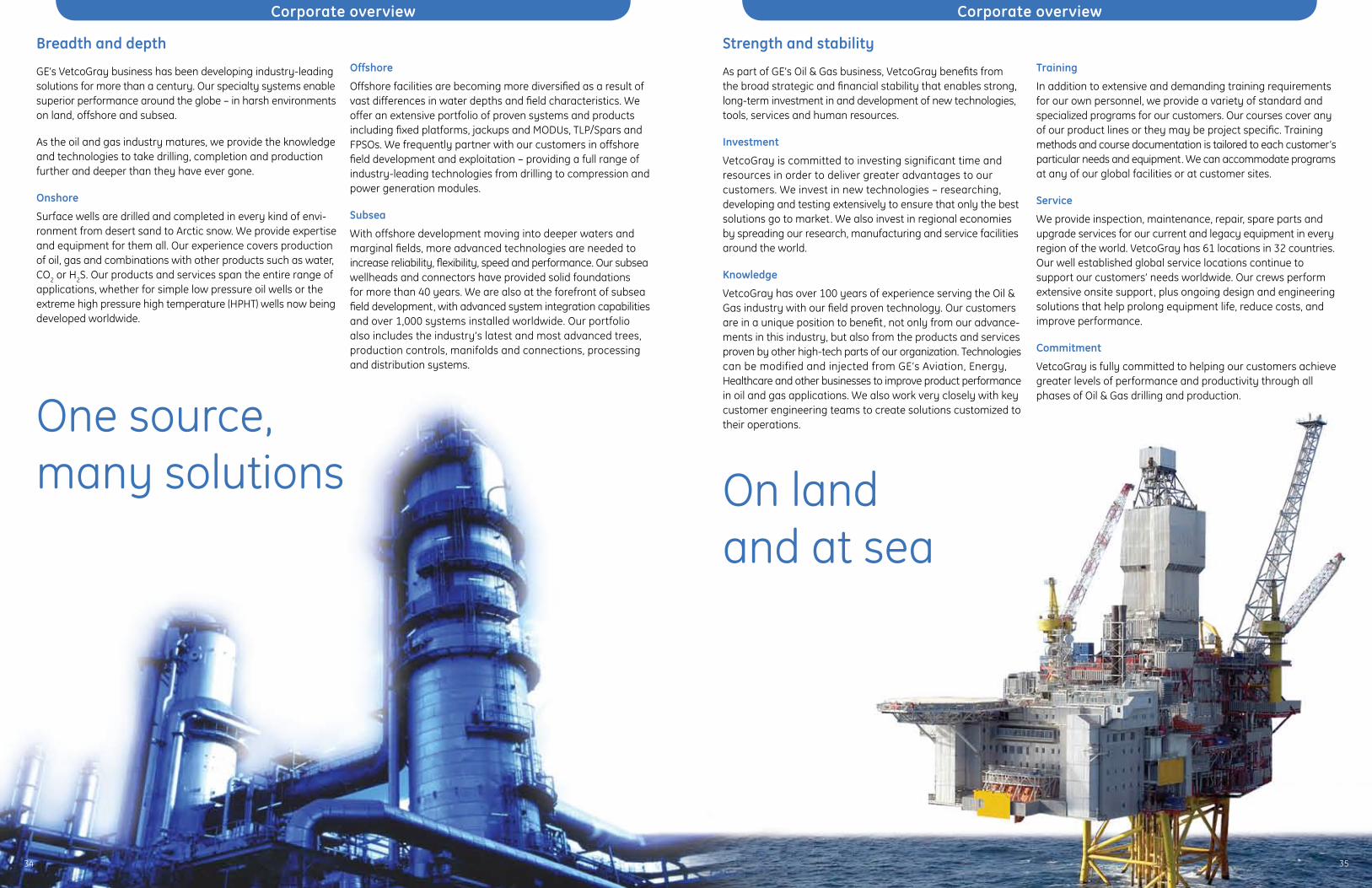
34 35
Corporate overview Corporate overview
Breadth and depth
GE’s VetcoGray business has been developing industry-leading solutions for more than a century. Our specialty systems enable superior performance around the globe – in harsh environments on land, offshore and subsea.
As the oil and gas industry matures, we provide the knowledge and technologies to take drilling, completion and production further and deeper than they have ever gone.
Onshore
Surface wells are drilled and completed in every kind of envi-ronment from desert sand to Arctic snow. We provide expertise and equipment for them all. Our experience covers production of oil, gas and combinations with other products such as water, CO2 or H2S. Our products and services span the entire range of applications, whether for simple low pressure oil wells or the extreme high pressure high temperature (HPHT) wells now being developed worldwide.
Offshore
Offshore facilities are becoming more diversified as a result of vast differences in water depths and field characteristics. We offer an extensive portfolio of proven systems and products including fixed platforms, jackups and MODUs, TLP/Spars and FPSOs. We frequently partner with our customers in offshore field development and exploitation – providing a full range of industry-leading technologies from drilling to compression and power generation modules.
Subsea
With offshore development moving into deeper waters and marginal fields, more advanced technologies are needed to increase reliability, flexibility, speed and performance. Our subsea wellheads and connectors have provided solid foundations for more than 40 years. We are also at the forefront of subsea field development, with advanced system integration capabilities and over 1,000 systems installed worldwide. Our portfolio also includes the industry’s latest and most advanced trees, production controls, manifolds and connections, processing and distribution systems.
Strength and stability
As part of GE’s Oil & Gas business, VetcoGray benefits from the broad strategic and financial stability that enables strong, long-term investment in and development of new technologies, tools, services and human resources.
Investment
VetcoGray is committed to investing significant time and resources in order to deliver greater advantages to our customers. We invest in new technologies – researching, developing and testing extensively to ensure that only the best solutions go to market. We also invest in regional economies by spreading our research, manufacturing and service facilities around the world.
Knowledge
VetcoGray has over 100 years of experience serving the Oil & Gas industry with our field proven technology. Our customers are in a unique position to benefit, not only from our advance-ments in this industry, but also from the products and services proven by other high-tech parts of our organization. Technologies can be modified and injected from GE’s Aviation, Energy, Healthcare and other businesses to improve product performance in oil and gas applications. We also work very closely with key customer engineering teams to create solutions customized to their operations.
Training
In addition to extensive and demanding training requirements for our own personnel, we provide a variety of standard and specialized programs for our customers. Our courses cover any of our product lines or they may be project specific. Training methods and course documentation is tailored to each customer’s particular needs and equipment. We can accommodate programs at any of our global facilities or at customer sites.
Service
We provide inspection, maintenance, repair, spare parts and upgrade services for our current and legacy equipment in every region of the world. VetcoGray has 61 locations in 32 countries. Our well established global service locations continue to support our customers’ needs worldwide. Our crews perform extensive onsite support, plus ongoing design and engineering solutions that help prolong equipment life, reduce costs, and improve performance.
Commitment
VetcoGray is fully committed to helping our customers achieve greater levels of performance and productivity through all phases of Oil & Gas drilling and production.
One source,many solutions On land
and at sea
34 35

GE Oil & Gas
Headquarters Nuovo Pignone S.p.A. Via Felice Matteucci 2 50127 Florence Italy T +39 055 423 211 F +39 055 423 2800 [email protected]
VetcoGray Inc. Headquarters 3010 Briarpark Avenue, Suite 300 Houston, Texas 77042 P.O. Box 2291 Houston, Texas 77252-2291 T +1 713 683 2400 F +1 713 683 2421
For complete contact information, please refer to our website.
www.geoilandgas.com/vetcogray
The information contained herein is general in nature and is not intended for specific construction, installation or application purposes. GE reserves the right to make changes in specifications or add improvements at any time without notice or obligation.
©2008 General Electric Company
All Rights Reserved
GEOG_SCP_Brochure_011108_V2
GE imagination at work