Embed Size (px)
Citation preview

DM710
Digital Automatic Voltage Regulator (AVR)
SPECIFICATION AND CONTROLS
English Original Instructions 5-2020 A065B341 (Issue 1)

5-2020
A065B341 Issue 1 2 Copyright © 2020 Cummins Inc.
Table of Contents 1 Description .................................................................................................................... 3
1.1 Self-Excited AVR Controlled Alternators ............................................................................ 3 1.1.1 Main Stator Powered AVR ................................................................................................. 3
2 Specification .................................................................................................................. 3 2.1 DM710 Technical Specification ......................................................................................... 3
3 Controls ........................................................................................................................ 5 3.1 Initial AVR Setup ............................................................................................................... 7 3.2 Adjust the AVR [VOLTS] Voltage Control ......................................................................... 8 3.3 Adjust the AVR [STAB] Stability Control ........................................................................... 9 3.4 Adjust the AVR [kVA] Max kVA Control ............................................................................ 9

5-2020
A065B341 Issue 1 3 Copyright © 2020 Cummins Inc.
1 Description 1.1 Self-Excited AVR Controlled Alternators
1.1.1 Main Stator Powered AVR The AVR provides closed loop control by sensing the alternator output voltage at the main stator windings and adjusting the exciter stator field strength. Voltage induced in the exciter rotor, rectified by the rotating diodes, magnetises the rotating main field which induces voltage in the main stator windings. A self-excited AVR receives power from the alternator output terminals or a special auxiliary winding in the main stator winding.
2 Specification 2.1 DM710 Technical Specification
Sensing Input o Voltage: 195 VAC to 280 VAC (delta) or 360 VAC to 485 VAC (star) o Frequency: 50 Hz to 60 Hz nominal
Power Input o Voltage: 70VAC to 140VAC 1 phase only o Frequency: 50 Hz to 60 Hz nominal
Power Output o Voltage: maximum 100 VDC at 115 VAC input o Current o continuous: 5 A o Transient: 12 A for 8 seconds o Resistance: 6 Ω minimum
No Description No Description . .
1 Main field (rotor) 5 AVR
2 Rotating diodes 6 Main armature (stator) or auxiliary winding (if fitted)
3 Exciter armature (rotor) 7 Output
4 Exciter field (stator) 8 Rotor shaft

5-2020
A065B341 Issue 1 4 Copyright © 2020 Cummins Inc.
Regulation o +/- 0.5% RMS with Linear Load
Thermal Drift o Typically, 0.0125% per 1 °C change in AVR ambient temperature
Typical Response o AVR response in 5 ms o Machine Volts to 97% in 300 ms
External Voltage Adjustment o +/-5% with 100 kΩ trimmer
Unit Power Dissipation o Max 8 W at 5 ADC output
Build-up Voltage o 3 VAC at AVR terminals
Under-Frequency Protection o Set point to 95% Hz of nominal value (50 or 60Hz)
Output voltage limitation in case of highly unbalanced loads o Phase not loaded cannot increase the voltage beyond 13% of the setup voltage o Red LED blinking
Over-excitation voltage control o AVR protects the alternator by limiting the excitation (Calibrated in factory at moment of final
inspection) Short-circuits protection
o Alarm set points: 3-phase 8 sec, phase-phase 5 sec, phase-neutral 2 sec High AVR operating temperature
o If the AVR temperature exceeds 70°C the output Voltage is limited until the AVR temperature falls below 70°C and at 85°C or above, there is a sudden Voltage drop and to reset the alarm the Genset must be stopped. Environmental
o Operating temperature: -20 °C to +70 °C o Relative Humidity: 0 °C to 70 °C: 95% o Storage temperature: -40 °C to +85 °C
Weight: 460g

5-2020
A065B341 Issue 1 5 Copyright © 2020 Cummins Inc.
3 Controls DANGER
Live Electrical Conductors Live electrical conductors can cause serious injury or death by electric shock and burns. To prevent injury and before removing covers over electrical conductors, isolate the generator set from all energy sources, remove stored energy and use lock out/tag out safety procedures.
DANGER Live Electrical Conductors Live electrical conductors at output, AVR and AVR accessory terminals, and AVR heat sink can cause serious injury or death by electric shock and burns. To prevent injury, take suitable precautions to prevent contact with live conductors including personal protective equipment, insulation, barriers and insulated tools.
NOTICE Refer to alternator wiring diagram for connection details.
Ref. Control Function Turn potentiometer CLOCKWISE to
P1 AVR (Volts) Adjust alternator output Voltage Increase voltage
Re (opt) Remote AVR Volts Adjustment Potentiometer (100kΩ)
Adjust alternator output Voltage remotely
Increase voltage by AVR voltage adjustment pot Re (opt)
P2 AVR (Stab) Adjust stability to prevent Voltage hunting. (Calibrated in factory at moment of final inspection)
Increase damping effect
P3 AVR (Droop) Function currently not available N/A
P5 Maximum kVA AVR protects the alternator by limiting the excitation (Calibrated in factory during final inspection)
N/A
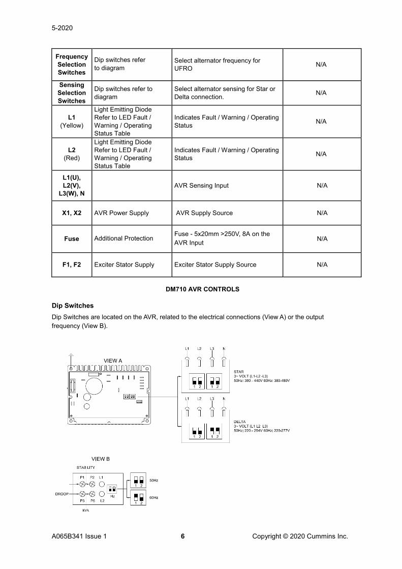
P1 P2 L1
P3 P5 L2
FUSE
SENSINGSELECTION
FREQUENCY SELECTION
VIEW BVIEW A
Re (opt)
5-2020
A065B341 Issue 1 6 Copyright © 2020 Cummins Inc.
Frequency Selection Switches
Dip switches refer to diagram
Select alternator frequency for UFRO N/A
Sensing Selection Switches
Dip switches refer to diagram
Select alternator sensing for Star or Delta connection. N/A
L1 (Yellow)
Light Emitting Diode Refer to LED Fault / Warning / Operating Status Table
Indicates Fault / Warning / Operating Status N/A
L2 (Red)
Light Emitting Diode Refer to LED Fault / Warning / Operating Status Table
Indicates Fault / Warning / Operating Status N/A
L1(U), L2(V),
L3(W), N AVR Sensing Input N/A
X1, X2 AVR Power Supply AVR Supply Source N/A
Fuse Additional Protection Fuse - 5x20mm >250V, 8A on the AVR Input N/A
F1, F2 Exciter Stator Supply Exciter Stator Supply Source N/A
DM710 AVR CONTROLS
Dip Switches Dip Switches are located on the AVR, related to the electrical connections (View A) or the output frequency (View B).
5-2020
A065B341 Issue 1 7 Copyright © 2020 Cummins Inc.
NOTICE Attention! If You are going to change the factory setting be very careful to set them correctly. Correct settings are reported later in the wiring diagram of this manual and also in the quick reference label stuck on the bottom side of the terminal box cover. Adjust the Dip Switch gently using an appropriate screwdriver: once the ON-OFF position has been reached, do not force further.
LED Fault / Warning / Operating Status
led status Alarm * cause AVR action Alarm reset **
L1, L2 ON, OFF --- • None (regular operation) --- ---
L1 blinking W0 • Underspeed operation Decreases the output voltage
Auto
L2 blinking A1 • Unbalanced voltages (due to unbalanced load)
Limits the output voltage Auto
L2 2x blinking
A2 • Prolonged overload • high winding temperature • wrong P5 setting
Limits the excitation current (and consequently voltage and power)
Auto
L2 3x blinking
A3 • High AVR temperature >70°C
Limits the excitation current (and consequently voltage and power)
Auto
L2 ON A4 • Heavy overload • short-circuit • AVR temperature > 85 °C • lack of sensing connection • unidentified electrical
connection
Abruptly drops the voltage Manual
* L1 and L2 status LEDs can indicate alarms simultaneously, so warning W0 (L1 blinking) can show with alarms A1-A4.
** Auto: alarm will stop once the fault that caused it is removed. Manual: The genset needs to be switched off and restarted after having removed the fault. (wait 10 seconds once the fault has been removed before starting up).
3.1 Initial AVR Setup NOTICE
The AVR must be setup only by authorized, trained service engineers. Do not exceed the designed safe operating voltage, shown on the alternator rating plate.
The AVR controls are set at the factory for initial running tests. Check that the AVR settings are compatible with your required output. To set up a replacement AVR, follow these steps:
1. Stop and isolate the generator set.
2. Install and connect the AVR.
3. Turn the AVR [VOLTS] volts control P1 fully counter-clockwise.
4. Turn the hand trimmer (if fitted) to 50%, the midway position.
5. Turn the AVR [STAB] stability control P2 to 50%, the midway position.

5-2020
A065B341 Issue 1 8 Copyright © 2020 Cummins Inc.
6. Connect a suitable voltmeter (0 to 300 VAC range) between one output phase and neutral.
7. Start the generator set with no load.
8. Adjust speed to nominal frequency (50 to 53 Hz or 60 to 63 Hz).
9. Carefully turn AVR [VOLTS] control P1 clockwise until the voltmeter shows rated voltage.
10. If voltage is unstable, adjust the AVR [STAB] stability control P2.
11. Re-adjust the AVR [VOLTS] control P1, as needed.
3.2 Adjust the AVR [VOLTS] Voltage Control NOTICE
Do not exceed the designed safe operating voltage, shown on the alternator rating plate.
NOTICE Hand trimmer terminals may be above earth potential. Do not ground any of the hand trimmer terminals. Grounding hand trimmer terminals could cause equipment damage.
To set the output voltage AVR [VOLTS] control on the AVR:
1. Check the alternator nameplate to confirm the designed safe operating voltage.
2. Set the AVR [VOLTS] control P1 to minimum the fully counter-clockwise position.
3. Check that the remote hand trimmer is fitted.
NOTICE
If a remote hand trimmer is connected, set it to 50%, the midway position.
4. Turn the AVR [STAB] control P2 to 50%, the midway position.
5. Start the alternator and set at the correct operating speed.
6. Adjust the AVR [VOLTS] control P1 slowly clockwise to increase the output voltage.
NOTICE
If the voltage is unstable set the AVR stability before proceeding
7. Adjust the output voltage to the desired nominal value (VAC).
8. If instability is present at rated voltage, refer to the AVR [STAB] adjustment P2, then adjust AVR [VOLTS] P1 again, if necessary.
9. If a remote hand trimmer is connected, check its operation.
NOTICE 0% to 100% rotation corresponds to 95% to 105% VAC
The AVR [VOLTS] control is now set.

5-2020
A065B341 Issue 1 9 Copyright © 2020 Cummins Inc.
3.3 Adjust the AVR [STAB] Stability Control 1. Check the nameplate to confirm the power rating of the alternator.
2. Set the AVR [STAB] control P2 to approximately 75% position.
3. Start the alternator and set at the correct operating speed.
4. Verify that the alternator voltage is within safe limits.
NOTICE
If the voltage is unstable go immediately to step 5.
5. Adjust the AVR [STAB] control P2 slowly counter-clockwise until the output voltage becomes unstable.
6. Adjust the AVR [STAB] control P2 slowly clockwise until the voltage is stable.
7. Adjust the AVR [STAB] control P2 a further 5% clockwise.
The AVR [STAB] control is now set.
3.4 Adjust the AVR [kVA] Max kVA Control NOTICE
The AVR [kVA] control is set at the factory to protect the alternator from over-excitation usually caused by overload. Incorrect AVR [kVA] control setting could damage the alternator components. Depending on the alternator model it must be set in the correct specific position, as detailed below.
P5 [kVA] limits the maximum excitation voltage of the alternator and therefore the maximum output power of the generator. This parameter is an integral over time, allowing a 200%-300% overload for a few seconds without limiting and illuminating L2 (Red LED blinking 3 times) or a slight overload for a longer period.
Alternatormodel
P5
N10G4 7
N15G4 6
N20G4 8
NOTICE
Readjust the voltage level if necessary (see Section 3.2 on page 8).

5-2020
A065B341 Issue 1 10 Copyright © 2020 Cummins Inc.
It is adjusted to an excitation voltage which corresponds to approximately 105% at operating temperature. This means that the generator can also give 110-115% of the nominal power when the machine is cold without P5 function limiting.

5-2020
A065B341 Issue 1 11 Copyright © 2020 Cummins Inc.