Embed Size (px)
Citation preview

IS 13947 ( Part 3 ) : 1993
IEC Pub 947-3 ( 1990 ) [ Superseding IS 4064 ( Parts 1 and 2 ) ]
SPECIFICATION FOR LOW-VOLTAGE SWITCHGEAR AN,D
CONTROLGEAR
PART 3 SWITCHES, DISCONNdCTORS, SWIS’CH DISCONNECTORS AND
FUSE COMBINATION UNITS * ‘k
( Second Reprint MAY 1997 )
UDC 621’316’542’064’241 : 621’316’923
s @I BIS 1993
AJREI~:~ 0F INDIAN STANDARDS MANAK BH;PVAN 9 BAYADUR SHAH ZAFAR MARG
NEW DELHI 110002
June 1993 Price Grou’p 14
-

IS 13947 ( Part 3 ) : 1993
IEC Pub 947-3 ( 1990)
Indian Standard
SPECIFICATION FOR LOW-VOLTAGE SWITCHGEAR AND
CONTROLGEAR
PART 3 SWITCHES, DISCONNECTORS. SWITCH DISCONNECTORS AND
FUSE COMBINATION UNITS
NATIONAL FOREWORD
This Indian Standard ( Part 3 ) which is identical with IEC Pub 947-3 ( 1990 ) is one in the series of standards on LV switchgear equipment covering requirements for switches and their family of items together with fuse combination units. This standard shall be read in conjunctron with Part 1 of this standard covering general requirements.
The text of the IEC Standard has been considered and approved by ET 07, Low Voltage Switch- gear and Controlgear Sectional Committee of BIS, as suitable for publication as Indian Standard, superseding the contents of IS 4064 ( Parts 1 and 2 ).
With reference to the definitions contained in 2.5 and 2.6 ,>f this standard, it is stated that the terms ‘Switchfuse’ and ‘Fuseswitch’ have been defined in these clauses due ta these terms being in vogue though however no distinction is being made in so far as requirements and tests for compliance are concerned.
CROSS REFERENCE
In this Indian Standard the following International Standards are referred to. Read in their respective place the following:
International Standard ( IEC ) Indian Standard
50 (441) (1984) IS 1885 ( Part 17 )
417 ( 1973 ) Nil
617-7 ( 1983 ) IS 12032 ( Part 7 )
In the case of IEC Pub 417, noting that Indian Standard identical to this is under print, the Technical Committee responsible for this standard has decided that it is acceptable for use in conjunction with this standard.

As in the Original Standard, this Page is Intentionally Left Blank

IS 13947 ( Part 3 ) : 1993 IEC Pub 947 - 3 ( 1990 )
CONTENTS
Page
Clause
1. General . . . . . . . . . . . . . . . . . . . . . . . . . . . . . . . . . . . . . . . . . . . . . . . . . . . . . . .
1.1 Scope . . . . . . . . . . . . . . . . . . . . . . . . . . . . . . . . . . . . . . . . . . . . . . . . . . . . 1.2 Object . . . . . . . . . . . . . . . . . . . . . . . . . . . . . . . . . . . . . . . . . . . . . . . . . . . .
2. Definitions . . . . . . . . . . . . . . . . . . . . . . . . . . . . . . . . . . . . . . . . . . . . . . . . . . . . & .$
3. Classification . . . . . . . . . . . . . . . . . . . . . . . . . . . . . . . . . . . . . . . . . . . . . . . . . . , 1.. ‘,
4. Characteristics . . . . . . . . . . . . . . . . . . . . .._.........................
4.1 Summary of characteristics ...............................
4.2 Type of equipment .......................................
4.3 Rated and limiting values for the main circuit .............
4.4 Utilization category .......................................
4.5 Control circuits .......................................... 4.6 Auxiliary circuits .........................................
4.7 Relays and releases ......................................
4.8 Vacant ................................................... 4.9 Switching overvoltages ...................................
5. Product information ............................................ 14
5.1 Nature of information ..................................... 14
5.2 Marking .................................................. 14
5.3 Instructions for installation, operation and maintenance ... 15
6. Normal service, mounting, and transport condi.
7. Constructional and performance requirements
7.1 Constructional requirements . . . . . . . . . . .
tions . . . . . . . . . . . .
..................
..................
7.2 Performance requirements ..................... ). ..........
7.2.1 Operating conditions ......... ., .....................
7.2.2 Temperature-rise ..................................
7.2.3 Dielectr+ic properties ...............................
7.2,4 Ability, to make and break under no-load, normal load and overload conditions .......................
7.2.5 Abilit$: to make, break or withstand short-circuit currenlts ..........................................
7.2.6 Switching overvoltages ............................
7.2; 7 Additional performance requirements for equipment suitable for isolation ...............................
5
5
6
6
9
9
1:
10
12
:z
14
i4 14
15
16
16
17
17
17
17
17
20
21
21
3

IS 13947 (Part 3 ) : 1993 IEC Pub 947 - 3 i 1990 )
‘Clause
8. Tests .........................................................
8.1 Kinds of tests ........................................... 8.2 Type tests for constructional requirements ................
8.3 Type tests for performance ...............................
8.3.1 Test sequences .................................... 8.3.2 General test conditions ............................
8.3.3 Test sequence I: General performance character- istics ..............................................
8.3.4 Test sequence I I i Operational performance capability .........................................
8.3.5 Test sequence Ill: Short-circuit performance capability .........................................
8.3.6 Test sequence IV: Conditional short-circuit current ...........................................
8.4 Routine tests ............................................ 8.5 Special tests ... :+. ......... :f ...........................
j Y,,
APPENDIX A - Equipment for direct switching of a single motor .....
APPENDIX B - Clearances and creepage distances ...................
APPENDIX C - Items subject to agreement between manufacturer and user ............................................
TABLES
I.
II.
III.
IV.
V.
VI.
VII.
VIII
IX.
X.
Xl.
XII.
Summary of equipment definitions ............................
Utilization categories ........................................
Verification of rated making and breaking capacities - Conditions for making and breaking corresponding to the various utilization categories .................................
Verification of operational performance - Number of operating cycles corresponding to the rated operational current ........
Test circuit parameters for Table IV .........................
Actuator test force ...........................................
List of type tests applicable to a given equipment ...........
Overall scheme of test sequences ............................
Test sequence I : General performance characteristics .......
Dielectric tegt voltage corresponding to the rated insulation voltage . . . . . . . . . . . . . . . . . . . . . . . . . . . . . . . . . . . . . . . . . . . . . . . . . . . . . .
Test seque,qce I I : Operational perfor’mance capability . . . . . , . . .
Test sequeice 1 I I : Short-circuit performance capability . . . . . .
XIII. Test sequence IV: Conditional short-circuit current . . . . . . . , . . . 41
Page
21
21
21
25
25 25
26 ,
32
35
40
42
43,
44
52
54
8
13
18
19
20
22
24
25
27
29
33
36
4

IS 13947 (Part 3) : 1993 IEC Pub 947 - 3 ( 1990 )
General
The provisions of the general rules dealt with in Part 1 (IEC Pu- blication 947-l) are applicable to this standard, where specifically called for. Clauses and sub-clauses, tables, figures and appendices of
the general rules thus applicable are identified by reference to Part 1,
e.g., Sub-clause 1.2.3 of Part 1, Table IV of Part 1, or Appendix A of Part 1.
Il. 1 Scope 4 3 .
This standard applies to swi&hes, disconnktors, switch-disconnec- tors and fuse-combination units to be used in distribution circuits and motor circuits of which the rated voltage does not exceed 1 000 V a.c.
or 1 500 V d.c.
The manufacturer shall specify the type, ratings and characteristics according to the relevant standard of any incorporated fuses.
This standard does not apply to equipment coming within the scope of IEC Publications 947-2, 947-4-l and 947-5-1; however, when switches and fuse-combination units coming into the scope of this standard are normally used to start, accelerate and/or stop an indi- vidual motor they shall also comply with the additional requirements given in Appendix A.
This standard does not include the additional requirements necessary for electrical apparatus for explosive gas atmospheres.
No tcs l.- Depending on its design, a switch (or disconnector) can be
referred to as "a rotary switch (disconnector)", "cam-
operated switch (disconnector)", "knife--switch (disconnec-
for)", etc.
2.- If they are not manually operated, switches and discon-
nectors may have to comply with additional requirements.
3.- In this standard, the word "switch" also applies to the
apparatus'referred to in French as "commutateurs", intended
! to modify the connections between several circuits and
inter al.ta to substitute a part of a circuit for another.
i 4.- In general, throughout this standard switches, disconnec-
tors, switch-disconnectors and fuse-combination units will .
be referred to as "equipment".

IS 13947 (Part 3 ) : 1993 IEC Pub 947 - 3 ( 1990 )
1.2 Object
The object of this standard is to state:
a) the characteristics of the equipment;
6) the conditions with which the equipment shall comply with refer- ence to:
1) operation and behaviour in normal service;
2) operation and behaviour in case of specified abnormal conditions, e.g. short circuit;
3) dielectric properties;
c) the tests for confirming that these conditions have been met and the methods to be adopted for these tests;
d) the information to be marked on the equipment or made ‘available by the manufactur4r, e.g. inphe catalogue.
* I,. .,
2. Definitions
For the majority of the definitions required in connection with this standard, see Clause 2 of Part 1.
Necessary additional definitions are given in this clause together with pertinent device definitions. The device definitions are also summarised in Table I.
2.1 Switch (mechanical) (IEV 441-14-10)
A mechanical switching device capable of making, carrying and breaking currents under normal circuit conditions which may include specified operating overload conditions and also carrying for a specified time currents under specified abnormal circuit conditions such as those of short-circuit.
Note.- A switch may be capable of making, but not breaking, short-
circuit currents.
2.2 Disconnector
A mechanical switching device which, in the open position, complies with the requirements specified for the- isolating function.
Notes l.- This definition differs from IEV 441-14-05 by referring to
I isolating function instead of isolating distance.
2..-, A disconnector is capable of opening and closing a circuit
i when either a negligible current is broken or made, or when
no significant change in the voltage across the terminals
of each of the poles of the disconnector occurs. It is also
capable of carrying currents under normal circuit con-
ditions and carrying for a specified time currents under'
abnormal conditions such as those of short circuit.

IS 13947(Part3):1993 IEC Pub947-3(1990)
2.3 Switch-disconnector (IEV 441-74-72)
A switch which, in the open position, satisfies the isolating requiremer,ts s’pecified for a disconnector.
2.4 Fuse-combination unit (IEV 441- 14-04)
A combination of a mechanical switching device and one or more fuses in a composite unit, assembled by the manufacturer or in accord- ance with his instructions.
Note.- (Not included in IEV 441-14-04). This is a general term for fuse switching devices (see also Sub-clauses 2.5 to 2.10 and
Table I).
2.5 Switch-fuse (IEV 441-14-14)
A switch in which one or more poles have a fuse in series in a composite unit.
2.6 Fuse-switch (IEV 441-14-17) & .#
A switch in which a fuse-linkior a fuse-carrier with fuse-link forms the moving contact.
2.7 Disconnector-fuse [IEV 441-14-15)
A disconnector in which one or more poles have a fuse in series in a. composite unit.
2.8 Fuse-disconnector (IEV 441-14-18)
A disconnector in which a fuse-link or fuse-carrier with fuse-link forms the moving contact.
2.9 Switch-disconnector-fuse (IEV 441-14-16)
A switch-disconnector in which one or more poles have a fuse in series in a composite unit.
2.10 Fuse-switch-disconnector (IEV 441-14-19)
A switch-disconnector in which a fuse-link or a fuse-carrier with fuse-link forms the moving contact.
2.11 Dependent manual operation (of a mechanical switching device) (IEV 441-16-13)
An operation solely by means of directly applied manual energy such that the speed and force of the operation are dependent upon the action of the operator.
2.12 Independent manualr operation (of a mechanical switching device) (IEV 441.-16- 16)
A stored energy speration where the energy originates from manual power, stored and released in one continuous operation , such that the speed and force of the operation are independent of the action of the operator. .
7

IS 13947 ( Part 3 ) : 1993 IEC Pub 947 - 3 ( 1990 )
2.13 Semi-independent manual operation
An operation solely by means of directly applied manual energy such that the manual force is increased up to a threshold value beyond which the independent switching operation is achieved unless deliber- ately delayed by the operator.
2.14 Stored energy operation (of a mechanical switching device) (IEV 441-16-15)
An operation by means of energy stored in the mechanism itself prior to the completion of the operation and sufficient to complete it under predetermined conditions.
Note.-- This kind of operation may be subdivided according to:
1. the manner of storing the energy (spring, weight, etc.);
2. the origit&f the eneygy (manual, electric, etc.);
3. the mannqr,, of releasing the energy (manual, electric,
etc.).
TABLE I
Summary of equipment definitions
Making and breaking current
Function
Isolating Making, breaking and isolating
&itch Disconnector Switch - disconnector
2.1 2.2 2.3
--C- --C- -A-
Fuse-combination unit 2.4
Switch-fuse Disconnector-fuse Switch- disconnector-fuse
2.5 2.7 2.9
.+-:' -E/L' -ELLJ
E
Fuse-switch Fuse-disconnector Fuse-switch
. 6 disconnector
;
2.6 2.8 2.10
-J&L-- -&-
8

IS 13947 (Part 3 ) : 1993 IEC Pub 947 - 3 ( 1990 )
3.
3.1
3.2
3.3
3.4
4.
4.1
No fes l.- The fuse may be on either side of or in a stationary
position between the contacts of the equipment.
i.- All equipment may be single-break or multi-break.
3.- Numbers are sub-clause references of the relevant
definitions.
4.- Symbols are based on IEC Publication 617-7,
Classification
According to the utilization category
See Sub-clause 4.4.
According to the method of ope&ion of ma&ally operated equipment
dependent manual operation (s%e Sub-clause“2.11);
independent manual operation (see Sub-clause 2.12);
semi.-independent manual operation (see Sub-clause 2.13).
Note. - The method of operation on closing may be different from the
method for opening.
According to suitability for isolation
suitable for isolation (see Sub-clause 7.1.6 of Part 1 and Sub-clause 7.1.6.1);
not suitable for isolation.
According to the degree of protection provided
See Sub-clause 7.1.11 of Part 1.
Characteristics
Summary of characteristics
The characteristics of the equipment shall be stated in terms of the following as applicable:
type of equipment
rated and limiting
(Sub-clause 4.2);
values for the main circuit (Sub-clause 4.3).
utilization category (Sub-clause 4.4);
control circuits (SCb-clause 4.5);
auxiliary circuits (Sub-clause 4.6) ;
switching overvoltages (Sub-clause 4.9).

IS 13947 (Part 3 ) : 1993 IEC Pub 947 - 3 ( 1990 )
4.2 Type of equipment
The following shall be stated:
4.2.1 Number of poles
4.2.2 Kind of current
Kind of current (a.c. or d.c.) and, in the case of a.c., number of phases and rated frequency.
4.2.3 Number of positions of the main contacts (if more than two)
4.3 Rated and limiting values for the main circuit
Rated values are assigned by the manufacturer. They shall be stated in accordance with Sub-clauses 4.3.1 to 4.3.6.4 but it may not be necessary to establishall the rate$ values listed.
4.3.1 Rated voltages
, Y.,
An equipment is defined by the following rated voltages:
4.3.1 . 1 Rated operational voltage (Ue)
Sub-clause 4.3.1 .l. of Part 1 applies.
4.3.1 .2 Rated insulation voltage (Ui)
Sub-clause 4.3.1.2. of Fart 1 applies.
4.3.1.3 Rated impulse withstand voltage ((limp)
Sub-clause 4.3.1.3. of Part 1 applies.
4.3.2 Currents
An equipment is defined by the following currents:
4.3.2.1 Conventional free air thermal current (IthI
Sub-clause 4.3.2.1 of Part 1 applies.
4.3.2.2 Conventional enclosed thermaL current (Ithe)
Sub-clause 4.3.2.2 of Part 1 applies.
4.3..2.3 Rated operational currents (I,] (or rated operational powers)
Sub-claljse 4.3.2.3 of Part 1 applies. L‘
4.3.2.4 Rated uninterrupted current (lu)
Sub-clause 4.3.2.4 of Part 1 applies.

IS 13947 ( Part 3 ) : 1993 IEC Pub 947 - 3 ( 1990 )
4.3.3 Rated frequency
Sub-clause 4.3.3 of Part 1 applies.
4.3.4 Rated duty
The rated duties considered as normal are as follows:
4.3.4.1 Eight-hour duty
Sub-clause 4.3.4.1 of Part 1 applies.
4.3.4.2 Uninterrupted duty
Sub-clause 4.3.4.2 of Part 1 applies.
4.3.5 Normal load and overload characteristics
4.3.5.1 Ability to withstand motor
*I* .$
F$+tching overload currents
See Appendix A.
4.3.5.2 Rated making capacity
Sub-clause 4.3.5.2 of Part 1 applies with the following additions:
The rated making capacity is stated by reference to the rated operational voltage and rated operational current and to the utilization category according to Table Ill, Sub-clause 7.2.4.1.
Note. - In the case of disconnectors having a making capacity, although
they are of utilization category AC-20 or DC-20, this value may
be stated separately by the manufacturer together with the
relevant test parameters.
4.3.5.3 Rated breaking capacity
Sub-clause 4.3.5.3 of Part 1 applies with the following
The rated breaking capacity is stated by reference operational voltage and rated operational current and to category according to Table III, Sub-clause 7.2.4.1.
additions :
to the rated the utilization
Note.- In the case 'of disconnectors having a breaking capacity,
although they are of utilization category AC-20 or DC-20, this
value may be_,stated separately by the manufacturer together
with the relev i nt test parameters.
11

IS 13947 (Part 3 ) : 1993 IEC Pub 947 - 3 ( 1990 )
4.3.6 Short-circuit characteristics
4.3.6.1 Rated short-time withstand current (loI
The rated short-time withstand current of a switch, a disconnector or a switch-disconnector is the value of short-time withstand current, assigned by the manufacturer, that the equipment can carry without any damage under the test conditions of Sub-clause 8.3.5.1.
The value of the rated short-time withstand current shall be not less than twelve times the maximum rated operational current and, unless otherwise stated by the manufacturer, the duration of the ‘current shall be 1 s.
For a.c., the value of the current is the r.m.s. value of the a.c. component and it is assumed that the highest peak value likely to occur does not exceed n times this r.m.s. value, the factor n being given by Table XVI of @t-t 1.
4
4.3.6.2 Rated short-circuit making capacity (I cm
)
The rated short-circuit making capacity of a switch or a switch- disconnector is the value of short-circuit making capacity assigned to the equipment by the manufacturer for the rated operational voltage, at rated frequency (if any) and at a specified power-factor (or time- constant). It is expressed as the maximum prospective peak current.
For a.c., the relationship between power-factor, prospective peak current and r.m.s. current shall be in accordance with Table XVI Part 1.
4.3.6.3 Vacant
4.3.6.4 Rated conditional -short-circuit current
Sub-clause 4.3.6.4 of Part 1 applies.
4.4 iJ tilization category
The utilization categories define the intended applications and are given in Table II.
Each utilization category is characterized by the values of the currents and voltages, expressed as multiples of the rated operational current and the rated operational voltage, as well as the power-factors or time-constants of the circuit. The conditions for making and breaking given in Table III correspond in principle to the applications listed in Table II.
t 1
The desihation of utilization categories is completed by the suffix A or B according to whether the intended applications require frequent or infrequent operations (see Table IV).
l
12

IS 13947 ( Part 3 ) : 1993 IEC Pub 947 - 3 ( 1990 )
Utilization categories with suffix B are appropriate for devices which, due to design or application, are only intended for infrequent operation. This could apply, for example, to disconnectors normally only operated to provide isolation for maintenance work or switching devices where the fuse-link blade forms the moving contact.
TABLE II
Utilization categories
Nature of current
Utilization category
Frequent Infrequent operation operation
AC-ZOA( * I AC-203~.* ’
Typical applications
Connecting and disconnecting und& no-load conditions
Alternating current
AC-21A
AC-22A
AC-Zlfj #,,
AC-22B
Switching of resistive loads including moderate overloads
. Switching of mixed resistive and inductive loads, including moderate overloads
AC-23A AC-23B . Switching of motor loads or other highly inductive loads
DC-2OA( * 1 DC-2OB( * 1 . Connecting and disconnecting under no-load conditions
Direct current
DC-21A
DC-22A
DC-21B
DC-22B
. Switching of resistive loads including moderate overloads
- Switching of mixed resistive and inductive loads, including moder- ate overloads (e.g. shunt motors)
DC-23A DC-23B Switching of highly inductive loads (e.g. series motors I
t*) The use of these utilization categories is not permitted in the United States of America.
Category AC-23 includes occasional switching of individual motors. The switching of capacitors or of tungsten filament lamps shall be subject to agreement between manufacturer and user.
The utilization categories referred to in Tables II and III do not apply to an equipment normally used to start, accelerate and/or stop individual motors. The utilization categories for such an equipment are dealt with in Appendix A.
4.5 Control circuits
Sub-clause 4.5 of
4.6 Auxiliary circuits
‘Sub-clause 4.6 of
Par+ 1 applies.
Part 1 applies.
13

IS 13947 ( Part 3 ) : 1993
IEC Pub 947 - 3 (1990)
4.7 Relays and releases
Sub-clause 4.7 of Part 1 applies.
4.8 Vacant
4.9 Switching overvoltages
Sub-clause 4.9 of Part 1 applies.
5. Product information
5.1 Nature of information
Sub-clause 5.1 of Part 1 applies as appropriate for a particular design.
5.2 Marking
Each equipment shall’be marked in a durable and legible manner with the following data:
a) Indication of the open and closed position. The open or closed position shall be respectively indicated by the graphical sym- bols 417-IEC-5007 or 417-IEC-5008 of IEC Publication 417 (see Sub-clause 7.1 .5.1 of Part 1);
6) Suitability for iso!ation.
The appropriate symbols of Table i shall be used.
c) Additional marking for disconnectors:
Devices of utilization category AC-20A, AC-20B, DC-20A and DC-20B shall be marked “Do not open under load” unless the device is interlocked to prevent such opening.
Note. - Symbols of the various types of equipment are given in
Table I.
The markings shall be on the equipment itself or on a nameplate or nameplates attached to the equipment, and shall be located at a place such that they are visible and legible from the front after mounting (see Sub-clause 6.3 of Part 1).
The following data shall also be marked on the equipment but need not be visible from the front when the equipment is mounted:
. I
d) manufacturer’s name or trade mark;
e) type designation or serial number;
14

IS 13947 (Part 3 ) : 1993 IEC Pub 947 - 3 ( 1990 )
rated operational currents (or rated powers) at the rated oper- ational voltage and utilization category (see Sub-clauses 4.3.1, 4.3.2 and 4.4);
value (or range), of the rated frequency or the indication “d.c. ” (or the symbol ); ----
for fuse-combination units, the fuse type and maximum rated current and the power loss of the fuse-link;
IEC 947-3, if the manufacturer claims compliance with this standard;
degree of protection of enclosed equipment (see Appendix C of Part 1);
The following terminals shall be identified:
k) line and load terminals Sub-clause 8.3.3.3.1);
u less the cjnnection is immaterial (see *!+
/) neutral pole terminal, if a*$plicable, by the letter “N” (see Sub- clause 7.1.7.4 of Part 1);
m) protective earth terminal (see Sub-clause 7.1.9.3 of Part 1);
The following data shall be made available in the manufacturer’s published information:
nl rated insulation voltage;
01 rated impulse withstand voltage for equipment suitable for isolation or when determined;
p) pollution degree, if different from 3;
9) rated duty;
r1 rated short-time withstand current and duration, where applicable;
s) rated short-circuit making capacity, where applicable;
t1 rated conditional short-circuit current, where applicable.
5.3 Instructions for installation, operation and maintenance
Sub-clause 5.3 of Part 1 applies.
6. Normal service, mounting, and transport conditions I
Clause 6 of Part 1( applies with the following addition:
Pol lution degree (see Sub-clause 6.1.3.2 of Part 1).
15

IS 13947 (Part 3 ) : 1993 IEC Pub 947 - 3 ( 1990 )
Unless otherwise stated by the manufacturer, the equipment is intended for installation under environmental conditions of pollution degree 3.
7. Constructional and performance requirements
7.1 Constructional requirements
Note.- Further requirements concerning materials and current-carrying parts are under consideration for Sub-clauses 7.1.1 and 7.1.2
of Part 1. Their application to this standard will be subject to further consideration.
Sub-clause 7.1 of Part 1 applies, with the following additions:
7.1.3 Clearances and creepage distances
& I For equipment for which the manufacturer has declared a value of
rated impulse withstand; voltage (Uimp), minimum values are given in
Tables XIII and XV of Part 1.
For other equipment, guidance for minimum values is given in
Appendix 6.
7.1.6.1 Additional constructional requirements for equipment suitable for isolation
The equipment shall be marked according to Sub-clause 5.26).
For equipment of rated operational voltage greater than 50 V, the strength of the actuating mechanism and the reliability of the indi- cation of the open position shall be checked according to Sub- clause 8.2.5. Moreover, when means are provided to lock the
equipment in the open position, locking shall only be possible when the main contacts are in the open position (see Sub-clause 8.2.5).
This requirement does not apply to equipment where the main contact position is visible in the open position and/or the open position is indicated by another means than the actuator.
When no indication is provided, all the main contacts shall be clearly visible in the open position.
The clearance across the open contacts of the same pole when in the open position shall not be less than the minimum clearances given in Table XIII of Part 1 and shall also comply with the requirements of Sub-clause’7.2.3.16) of Part 1.
. L
1‘
Note. - If auxiliary contacts are provided for interlocking purposes,
the operating time of the auxiliary contacts should be declared
by the manufacturer. l
16

IS 13947 (Part 3 ) : 1993 IEC Pub 947 - 3 ( 1990 )
7.1 .8 Additional requirements for equipment provided with a neutral pole
Sub-clause 7.1 .8 of Part 1 applies except for the note referring to an overcurrent release.
7.2 Performance requirements
7.2.1 Operating conditions
7.2.1.1 Genera/
Sub-clause 7.2.1 .l of Part 1 applies.
7.2.2 Temperature rise
7.2 3 Dielectric properties
7.2 4 Ability to make and break under conditions
7.2 4.1 Making and breaking capacities
Sub-clause 7.2.2 of Part 1 applies with the following addition:
.& $’ For fuse-combination units, the temperature rise of the fuse-link
contacts during the test according to Sub-ilause 8.3.3.1 shall not cause any damage of a nature which impairs the subsequent perform- ance of the equipment in test sequence I.
If the manufacturer has declared a value of the rated impulse
withstand voltage (Uimp ), the requirements of Sub-clause 7.2..3 of
Part 1 apply and the equipment shall satisfy the dielectric tests specified in Sub-clause 8.3.3.4 of Part 1.
If no value of the rated impulse withstand voltage has been de- clared, and for the verification of dielectric withstand specified in the relevant sub-clauses of this standard, the equipment shall satisfy the dielectric tests specified in Sub-clauses 8.3.3.2.1, 8.3.3.2.2, 8.3.3.2.3 and 8.3.3.2.4 of this standard.
no-load, normal load and overload
The rated making and breaking capacities are stated by reference to the rated operational voltage and rated operational current and to the utilization category according to Table III.
The test conditions are specified in Sub-clause 8.3.3.3.1.
17

I * I
!
TABLE III
Verification of rated making and breaking capacities (see Sub-clause 8.3.3.3) Conditions for making and breaking corresponding to the various utilization categories
Rated operational Making (1) Make-break
Number of Utilization category
current m -.- I/I u/u cos@ e
I/I cos$ .operating cycles
e e u,/u
e
AC-20AC2) - AC-20B(2) All values
AC-21A - AC-21B All values 1.5 1.05 0.95 1.5 1.05 0.95 5
AC-22A - AC-22B All values 3 1.05 0.65 3 1.05 0:65 5
AC-23A - AC-23B 0 < I I 1OOA 10 1.05 0.45 . Y+
1.05 0.45 5 e
1OOA < I 10 1.05 0.35 “8'< 1.05 0.35 3 e
Utilization category Rated operational I/I u/u L/R L/R Number of
current e e
(ms)
I/I e
u,/u e
(ms) operating cycles
DC-20A(2> - DC-20B(2) / All values 1 -
DC-21A - DC-21B All values 1.5 ; 1.05
ir. 1 1.5 1.05 1 5
DC-22A - DC-22B All values 4 1.05 2.5 . 4 1.05 2.5 5
DC-23A - DC-23B All values 4 1.05 15 4 1.05 15 5
I = Making current
I q Breaking current
IC = Rated' operational current e
u = Applied voltage
u = Rated operational voltage e
u = Power frequency or d.c. recovery voltage r
(1) For a.c. the making current is expressed by the r.m.5. value of the periodic component
of the current.
(2) Theyse of these utilization categories is not permitted in the United States of America.
9-

IS 13947 (Part 3 ) : 1993 IEC Pub 947 - 3 ( 1990 )
7.2.4.2 Operational performance
Tests concerning the verification of the operational performance of an equipment are intended to verify that the equipment is capable of making and breaking without failure, the currents flowing in its main circuit for the intended use.
The number of operating cycles and the test circuit parameters for the operational performance test for the various utilization categories are given in Tables IV and V.
The test conditions are specified in Sub-clause 8.3.4.1.
TABLE IV
Verification of operational performance Number of operatin&. cycles corresponding to
the rated operational &rrent
(1)
Rated operational current Ie
O<I < 100 100 < I8 2 315 < I=
315 7 630
630 < I = 2 2 500 ! 500 < I"e -
i 1. ‘.
(2) (31 (4) 15) (6) (7) 181
Number of operating cycles Number of operating AC and DC AC and DC cycles A categories 8 categories
per hour Without With current current
I
120 8 500 1 500 120 7 000 1 000 60 4 000 1 000 20 2 500 500 10 1 500 500
The values in the table apply to all utilization categories except AC-20A, AC-20B, DC-20A and DC-20B. These categories shall comply with the total number of operating cycles in columns 5 or 8, but all without current unless some breaking and/or making capacity is claimed (see notes to Sub-clauses 4.3.5.2 and 4.3.5.3). In this case the verification shall be made at the values of voltage, current and power-factor claimed and for the number of operating cycles given in the table. Column 2 gives the minimum operating rate. The operating rate for any utilization category may be increased with the consent of the manufacturer.
19

IS 13947 (Part 3) : 1993 IEC Pub 947 - 3 ( 1990 )
TABLE V
Test circuit parameters for Table IV
Value of the Making (11 Breaking Utilization rated operational . category current Ie I/I, UNe COSQ, Ic'Ie "rNe COSQ,
AC-21A AC-ZlB All values 1 1 0.95 1 1 0.95 AC-22A AC-22B All values 1 1 0.8 1 1 0.8 AC-23A AC-23B All values 1 1 8.65 1 1 0.65
I/I UN L/R Ic'Ie "r'"c
L/R e e Lms) Ims)
DC-21A DC-PlB All values 1 1 1 1 1 1 DC-22A DC-220 All values 1 1 2 1 1 2 DC-23A DC-238 All values 1 1 7.5 1 1 7.5
I q Making current
Ic = Breaking current 4
P
Ie = Rated operational y;rent
U = Voltage before make (Applied voltage)
U e
= Rated operational voltage
"r = Power frequency or d.c. recovery voltage
(11 For a.c., the making current is expressed by the r.m.s. value of the periodic component of the current.
7.2.4.3 Mechanical durability
Sub-clause 7.2.4.3.1 of Part 1 applies. Test conditions are specified in Sub-clause 8.5.1.
7.2.4.4 Electrical durability
Sub-clause 7.2.4.3.2 of Part 1 applies. Test conditions are specified in Sub-clause 8.5.2.
7.2.5 Ability to make, break or withstand short-circuit currents
The equipment shall be so constructed as to be capable of with- standing, under the conditions specified in this standard, the thermal, dynamic and electrical stresses resulting from short-circuit currents.
Short-circuit currents may be encountered during current making, current carrying in the closed position and current interruption.
The abil,ity of the equipment to make, carry and break short-circuit currents isi stated in terms of one or more of the following ratings:
1. Rated short-time withstand current (see Sub-clause 4.3.6.1) .
2. Rated short-circuit making capacity (see Sub-clause 4.3.6.2).
20

IS 13947 ( Part 3 ) : 1993 lEC Pub 947 - 3 ( 1990 )
3. Rated conditional short-circuit current (see Sub-clause 4.3.6.4).
7.2.6 Switching overvoltages
Sub-clause 7.2.6 of Part 1 applies.
7.2.7 Additional performance requirements for equipment suitabie for isolation
These requirements only apply to equipment with rated operational voltage greater than 50 V.
With the equipment in new condition and the contacts in the open position the equipment shall withstand the dielectric test of Sub- clause 8.3.3.2.
If tests according to Sub-clauses 8.3.3.3 and 8.3.4.1 have been made, the equipment in the condition after the tests shall meet the leakage current requirements of Sub-clause 8.3.3.5.
8. Tests
8.1 Kind of tests
8.1.1
8.1.2
General
Sub-clause 8.1.1 of Part 1 applies.
Type tests
Sub-clause 8.1.2 of Part 1 applies. Type tests are given in Table VI I of this standard.
8. 1.3 Routine tests
Sub-clause 8.1.3 of Part 1 applies. Routine tests are specified in Sub-clause 8.4.
8. 1.4 Sampling tests
Sampling tests for clearance verification according to Sub-
clause 8.3.3.4.3 of Part 1 are under consideration.
8.1.5 Special tests
Special tests Sub-clause 8.5.
(see Sub-clause 2.6.4 of Part 1) are specified in
8.2 Type tes$s for
E
constructional
Sub-clause 8 2 ‘if Part 1 clause 7.1. > i
requirements
applies. (See however note of Sub-
21

IS 13947 (Part 3 ) : 1993 IEC Pub 947 - 3 ( 1990 )
8.2.5 Verification of the strength of actuator mechanism and position indicating device
This sub-clause only applies to equipment suitable for isolation with a rated operational voltage greater than 50 V.
8.2.5.1 Condition of equipment for tests
The test on the actuator shall be part of test sequence I (see Sub-clause 8.3.3 and Table IX).
8.2.5.2 Method of test
The necessary force F for opening shall first be measured and the force should be applied to the extremity of the actuator.
With the equipment in the closed position, fixed and moving contacts of the pole for which the test is deemed to be the. most severe shall be kept closed by appropriate means. The actuator shall be submitted to the test force as defined in Table VI according to its type.
*. .$
This force shall be “applied without shock to the actuator in a direction to open the contacts for a period of 10 s.
The direction of the force, as shown in Figure 1, shall be maintained throughout the test.
If locking means are provided to lock the actuator in the open position it shall not be possible to lock the actuator in this position while the test force is applied.
8.2 5.3 Condi:ion of equipment after test
After the test and when the test force is no longer applied to the actuator with the actuator being left free, the indication of the open position shall not be wrongly given.
TABLE VI
Actuator test force
Type of actuator force
(N) -
Pushbuttolr Fig. la 3F 50 150 One-finger operated Fig. lb 3F 50 150 Two-finger operated Fig. lc 3F 100 200 One-hand operated 3F 150 400 Fig. Id and,le Two-hand op,erated Fig. If 3F L- ,
200 600 Two-hand operated Fig. lg 3F 200 600
S F is the normal operating force in new condition. The test force shall be JF with the stated minimum and maximum values and be applied as shown in Figure 1. .
Maximum test
22

900
P F
(a)
/ / 90" F
/ /
’ /’ ,‘. / *N P
(e)
IS 1,3947 (Part 3 ) : 1993 IJW Pub 947 - 3 ( 1990 )
. 900
. Oi- fit- F 900
F
(cl (d)
If) (9)
Fig. 1. - Actuator applied force F.
23


IS 13947 (Part 3) : 1993 IEC Pub 947 - 3 ( 1990 )
8.3 Type tests for performance
Performance type tests to which equipment may be submitted accord- ing to its kind are listed in Tabie VII.
8.3.1 Test sequences
Type tests are grouped together in a number of sequences as shown in .Table Vlii.
For each sequence, tests shall be made in the order listed in accord- ance with the requirements of ‘the appropriate sub-clause.
TABLE VIII
Overall scheme of test sequences
- 1.. “\‘
Sequence
General performance characteristidsY’ (see Sub-clause 8.3.3 and Table IX)
7 Tests
Temperature-rise Dielectric properties Making and breaking capacities (11 Dielectric verification Ill Leakage current ( 2 t Temperature-rise verification (1) Strength of actuator mechanism (21
Operational performance capability (see Sub-clause 8.3.4 and Table XII
Operational performance Dielectric verification Leakage current (21 Temperature-rise verification
Short-circuit performance capability (31 Short-time withstand current (see Sub-clause 8.3.5 and Table XII) Short-circuit making capacity
Dielectric verification Leakage current (2) Temperature-rise verification
Conditional short-circuit currant (31 (see Sub-clause 8.3.6 and Table XIII)
Fuse protected short-circuit withstand
Fuse protected short-circuit making
Dielectric verification Leakage current f 2 1 Temperature-rise verification
-
(1) Not required for disconnectors (AC-20 or DC-201. See notes of Sub-clauses 4.3.5.2 and 4.3.5.3.
(21 Only required for equipment suitable for isolation of rated voltage greater than 50 V.
(31 Either test sequence TII or test sequence IV to be made according to the ratings stated by the manufacturer.
--___
3.3.2 General test conhitions
8.3.2.1 General requitemen ts
i Sub-clause 8.3.2.1 of Part 1 applies to all type tests as applicable.
The equipment at the start of any test sequence shall be in new, and clean condition.

IS13947(Part.3):1993
IEC Pub 947 - 3 ( 1990 )
The force applied for any opening operation shall not be greater than the test force determined in Sub-clause 8.2.5.2 and shall be applied in the same manner without shock.
Where doubt exists as to the correct opening operation, no more than three attempts to operate the equipment to the open position are allowed.
8.3,2.2 Test quantities
Sub-clause 8.3.2.2 of Part 1 applies.
8.3.2.3 Evaluation of test results
The behaviour of the equipment during the tests and its condition after the tests are specified in the appropriate test clause.
8.3.2.4 Test report 4. f
Sub-clause 8.3.2.4 of Part 1 applies. \, 1 yp
8.3.3 Test sequence I: General performance characteristics
This test sequence applies to the types of equipment listed in Table IX and comprises the tests according to the table.
8.3.3.1 Temperature-rise
Sub-clause 8.3.3.3 of Part 1 applies with the following additions:
The test shall be made at the conventional enclosed thermal current I the (see Sub-clause 4.3.2.2 of Part 1).
Fuse-combination units shall be fitted with fuse-links having a rated current equal to the conventional thermal current of the combination unit.
The fuse-link shall have a power loss not exceeding the maximum value specified by the equipment manufacturer.
Note. - The test may be made with a "dummy" fuse-link of essentially
similar design to the standardized fuse-link and having the
-specified power loss.
Details of the fuse-links used for the test, i.e. the manufacturer’s name and reference, the rated current, the power loss of the fuse-link, and+ the breaking capacity, shall be given in the test
report. The ty,pe test with the specified fuse-links shall be deemed to cover the use of any other fuse-link having a power loss, at the
conventional thtermal current of the combination unit, not exceeding the power loss of i!he fuse-link used for the test.
26


IS 13947 (Part 3 ) : 1993 IEC Pub 947 - 3 ( 1990 )
0.3.3.2 Test ot dielectric properties
The test shall be made:
in accordance with Sub-clause 8.3.3.4 of Part 1 ii the manufac- turer has declared a value of the rated impulse withstand voltage u.
Imp (see Sub-clause 4.3.1.3);
in accordance with Sub-clauses 8.3.3.2.1, 8.3.3.2.2, 8.3.3.2.3 and
8.3.3.2.4, if no value of Uimp has been declared, and for the
verification of dielectric withstand in the relevant sub-clauses of this standard.
Equipment suitable for isolation shall be tested according to Sub- clause 8.3.3.4 of Part 1, with a value of test voltage as specified in
Table XIV of Part 1 and corresponding to the value of Uim declared
by the manufacturer. This requirement does not apply to P he verifi-
cation of dielectric withstand made during test sequences. & .$
8.3.3.2.1 Condition of the ‘kbuiptnent for tests
Dielectric tests shall be made on new equipment mounted approxi- mately as under usual service conditions, including internal wiring, and in a dry condition.
When the base of the equipment is of insulating material, metallic parts shall be placed at all the fixing points in accordance with the conditions of normal installation of the equipment and these parts shall be considered as part of the frame of the equipment. When the equip- ment is in an insulating enclosure, the latter shall be covered by a metal foil connected to the frame. If the operating handle is metallic,~ it shall be connected to the frame; if it is of insulating material, it shall be covered by a metal foil connected to the frame.
Equipment not supplied with an. enclosure but intended to be used in an enclosure shall be tested in an enclosure stated by the manufac- turer to be equivalent to the smallest that is applicable in service.
When the dielectric strength of the equipment is dependent upon the taping of leads or the use of special insulation, such taping or special insulation shall also be used during the tests.
8.3.3.2.2 Application of the test voltage
The test voltage shall be applied for 1 min as follows:
a) With the.,main contacts closed:
1) between all live parts of all poles connected together and the franle of the equipment;
2) between each pole and all the other poles connect’ed to the frame of the equipment.
28

IS 13947 (Part 3) : 1993 IECPub947-3(1990)
On equipment having more than one closed position, the test shall be carried out in each closed position.
b) With the main contacts open:
1) between all live parts of frame of the equipment;
2) between the terminals of
all poles connected together and the
one side connected together and the
terminals of the other side connected together.
For the purpose of the above tests, an insulated neutral is to be considered as a pole of the equipment.
,
On equipment having more than one open position, the test shall be carried out in each open position.
8.3.3.2.3 Value of the test voltage
The test voltage shall have a practically sinusoidal waveform and a frequency between 45 Hz an4 62 Hz. .$
The high-voltage transfor*mer used for the test shall be so designed that, when the output terminals are short-circuited after the output voltage has been adjusted to the appropriate test voltage, the output current is at least 200 mA.
The overcurrent relays shall not trip when the output current is less than 100 mA.
Glow discharges without drops in voltage are neglected.
Unless otherwise specified, the value of the test voltage shall be as given in Table X.
TABLE X
Dielectric test voltage corresponding to the rated insulation voltage
Rated insulation
voltage U. 1
Dielectric
test voltage
Ca.c)
(r.m.s.1
U.I 60
66 < U' I 300
30.0 < u' I 660
640 < u' I 800 a’d,o < ut 5 i 000
1 odo < ul I 1 500* 1
9c For d.c. only
29

IS 13947 (Part 3 ) : 1993 IECPub947-3(1990)
8.3.3.2.4 Results to be obtained
The test is considered to have been passed if there is no puncture or flash-over.
8.3.3.3 Making and breaking capacities
8.3.3.3.1 Test values and conditions
Sub-clause 8.3.3.5 of Part 1 applies regarding equipment provided with a neutral pole.
The test values are stated in Table Ill, Sub-clause 7.2.4.1, accord- ing to the utilization category.
The stated number of make-break operating cycles shall be made with a time interval between,’ close-open cycles of 30 s 2 10 s except that for equipment of conventional thermal current of 400 A or more, the time interval may be increased by agreement between manufacturer and user-and the intervaI3haII be sta#ed in the test report.
During each make-break operating cycle, equipment need only stay in the closed position for a period long enough to allow the switching o’peration to be completed and to enable the current value to be establi,shed and the moving parts of the equipment to come to rest. After each ape-rating cycle, the recovery voltage shall be maintained for at least 0.05 s.
For convenience of testing, equipment of utilization categories AC-23A
and AC-23 8 make-break operating cycles may be replaced, with the
agreement of the manufacturer, by the stated number of 10 I, make
cycles followed by the same number of 8 I, make-break cycles.
For a.c. the power-factor of the test circuit shall be determined in accordance with Sub-clause 8.3.4.1.3 of Part 1. The values shall be in accordance with Table Ill, Sub-clause 7.2.4.1.
For d.c. the time-constant of the test circuit shall be determined in accordance with Sub-clause 8.3.4.1.4 of Part 1. The values shall be in accordance with Table Ill, Sub-clause 7.2.4.1.
The test voltage and the load shall be applied to the appropriate terminals of the equipment. For equipment in which a moving contact remains connected to one of the terminals when the equipment is in the open ( position, this test shall be repeated with the supply and load connections interchanged, unless the terminals are specifically and clearly marked f”r load and supply.
.
30

In the case of tests may be replaced by electrically equivalent manufacturer.
8.3.3.3.2 Test circuit
IS 13947 (Part 3 ) : 1993 IEC Pub 947 - 3 ( 1990 )
carried out on fuse-combination units, fuse-links suitable copper links of dimensions and mass to those of the fuse-links recommended by the
Sub-clause 8.3.3.5.2 of Part 1 applies.
8.3.3.3.3 Trunsient recovery voltage
8.3
Sub-clause 8.3.3.5.3 of Part 1 applies only to utilization categories AC-22 and AC-23. For tests for utilization categories DC-22 and DC-23 the test circuit load may be replaced by a motor producing the specified current and time constant value if agreed between manufac- turer and user.
3.3.4 Switching overvoltage&
Under consideration. * a*
4
8.3.3.3.5 Be!laviour of equipment during making and breaking capacity tests
The equipment shall perform during the above tests in such a manner as not to endanger an operator or cause damage to adjacent equipment.
There shall be no permanent arcing or flash-over between poles or between poles and frame and no melting of the fuse in the detection circuit.
The equipment shall remain mechanically operable. Contact welding, such as to prevent an opening operation using normal operating means, is not permitted.
8.3.3.3.6 Condition of equipment after the making and breaking capacity tests
It shall be demonstrated immediately after the test that the equip- ment will close and open satisfactorily during a no-load close/open operation.
A closing operation is considered satisfactory when normal operation of the handle through its full stroke will close the contacts sufficiently for the equipment to be able to carry its rated operational current.
After the test and without maintenance the equipment shall comply with the requirements of Sub-clause 8.3.3.4.
The contacts shall be in a suitable condition to carry the rated operatiohal current without maintenance and shall comply with the temperature-rise derification of Sub-clause 8.3.3.6.
If the equipmeht is suitable for isolation, it shall comply with Sub-clauses 8.3.3.5 and 8.3.3.7.
31

IS 13947 (Part 3 ) : 1993 IEC Pub 947 - 3 ( 1990 )
8.3.3.4 Dielectric verification
8.3 3.5 Leakage current
After the test according to Sub-clause 8.3.3.3, a test shall be made to check that the equipment shall be capable, without maintenance, of withstanding a voltage equal to twice its rated insulation voltage according to Sub-clause 8.3.3.2.2.
This test is made only on equipment suitable for isolation of rated
operational voltage U, greater than 50 V. The leakage current shall be
checked across each contact gap and from each terminal to the frame.
The value of leakage current, with a test voltage equal to 1 .l times the rated operational voltage of equipment shall not exceed:
0.5 mA per pole for equipment of utilization category AC-20A, AC-20B, DC-20A or w-208; .$
2 mA per pole for equipment of all other utilization categories.
8.3.3.6 Temperature-rise verification
After the tests according to Sub-clause 8.3.3.3, the temperature-rise of the main terminals shall be checked according to Sub-clause 8.3.3.1, The terminals shall not exceed 80 K temperature-rise at the rated operational current of the utilization category of the equipment tested.
8.3.3.7 Strength of actuator mechanism
Sub-clause 8.2.5 applies to equipment suitable for isolation of rated operational voltage greater than 50 V.
8.3.4 Test sequence II: Operational performance capability
This test sequence applies to the types of equipment listed in Table Xl and comprises the tests according to this table.
They are made to verify compliance with Sub-clause 7.2.4.2.
a. 3.4.1 Operational performance test
8.3.4.1.1 Test values and conditions
The test values are stated in Tables IV and V, Sub-clause 7.2.4.2 according to the utilization category.
‘! The time ir/iterval between Table IV operating cycles with current
and without current and the sequential order of the tests shall be stated in the test report.
32

TABLE XI
Test sequence II: Operational performance capability
I,---
Type of equipment and oi-der of tests
Test sub- Fuse-switch Discormector- Switch-
clause No. Switd-, and Discomnzctor fuse and Switch- discornector-
switch-fuse fuse- discotnector fuse and
"r $$mnmector fuse-switch-
discornector
Operational performance 8.3.4.1 1 1 (1) 11) 1 1
Dielectric verification 8.3.4.2 2 2 1 1 2 2
Leakage current (2) 8.3.4.3 2 ur. 2 3 3
Tmperature-rise 8.3.4.4 3 3 3 verification _' 3 4 4
III Load-breaking operations are not recpired for category AC-20 and DC-20. see also notes of S&-clauses 4.3.5.2 and 4.3.5.3 as applicable.
(2) Test required only for Ue greater than 50 V.

IS 13947 (Part 3 ) : 1993 IEC Pub 947 - 3 ( 1990 )
During each make-break operating cycle, the equipment need only stay in the closed position for a period long enough to allow the switching operation to be completed and to enable the current’value to be established and the moving parts of the equipment to come to rest. After each operating cycle, the recovery voltage shall be maintained
for at least 0.05 s.
For a.c. the power-factor of the test circuit shall be determined in accordance with Sub-clause 8.3.4.1.3 of Part 1. The values shall be in accordance with Table V, Sub-clause 7.2.4.2.
For d.c. the time-constant of the test circuit shall be determined in accordance with Sub-clause 8.3.4.1.4 of Part 1. The values shall be in accordance with Table V, Sub-clause 7.2.4.2.
8.3.4.1.2 Test circuit 2. .$
Sub-clause 8.3.3.5.2 of Part 1 applies. ’
8.3.4.1.3 Transient recovery voltage
It is not necessary to adjust the transient recovery voltage.
8.3.4.1.4 Switching overvoltages
Under consideration.
8.3.4.1.5 Behaviour of the equipment during the operational performance test
The equipment shall perform during the above tests manner as not to endanger an operator or cause damage equipment.
in such a to adjacent
There shall be no permanent arcing or flash-over between poles or between poles and frame and no melting of the fuse in the detection circuit.
The equipment shall remain mechanically operable. Contact welding, such as to prevent an opening operation using normal operating means, is not permitted.
Some wear on the mechanism and contacts is allowed provided that the equipment functions correctly.
8.3.4.1 ,6 ! Condition of the equipment after the operational performance test
. L
It shall be idemonstrated immediately after the test that the equipment will close and open satisfactorily during a no-load close/open operation.
l
34

IS 13947 (Part 3 ) : 1993 IEC Pub 947 - 3 ( 1990 )
A closing operation is considered satisfactory when normal operation of the handle through its full stroke will close the contacts sufficiently for the equipment to be able to carry its rated operational current.
After the tests and without maintenance the equipment shall comply with the requirements of Sub-clause 8.3.4.2.
The contacts shall be in a suitable condition to carry the rated operational current without maintenance and shall comply with the temperature-rise verification of Sub-clause 8.3.4.4.
If the equipment is suitable for isolation, it shall comply with Sub-clause 8.3.4.3.
8.3.4.2 Dielectric verification
Sub-clause 8.3.3.4 applies.
8.3.4.3 Leakage current
Sub-clause 8 3 3 5 applies? . . . # I’
8.3.4.4 Temperature-rise verification
Sub-clause 8.3.3.6 applies.
8.3.5 Test sequence Ill: Short-circuit performance capability
This test sequence applies to the types of equipment listed in Table XII and comprises the tests according to this table.
This test sequence is not mandatory if a value of rated short-circuit making capacity is not stated by the manufacturer (see .Sub-clause 8.3.5.2.1) and test sequence IV (Sub-clause 8.3.6) is carried out.
The tests are made to verify compliance with Sub-clause 7.2.5.
8.3.5.1 Short- time withstand current test
8.3.5.1.1 Test values and conditions
The test conditions of Sub-clause 8.3.4.3 of Part 1 apply.
The test current shall be the rated short-time withstand current stated according to Sub-clause 4.3.6.1.
8.3.5.1.2 Test circuit
Sub-clause 8.3.4.1.2 of Part 1 applies.
For a.c., the with Sub-clause
For d.c., the with Sub-clause
power-factor of the test circuit shall be in accordance 8++3.4.1.3 of Part 1.
time-constant of the test circuit shall be in accordance 8.3.4.1.4 of Part 1.
35

TABLE XII
Test sequence III: Short-circuit performance capability
Type of equipment and order of tests
Test !%I.& Switch-
clause No. Fuse-switch Discumector-
fuse and Switch- discomector-
Switch and Discotmector switch-fuse fuse- disanmector
fuse and
disamiector fuse-switch-
discomector
Short-time withstand 8.3.5.1 1 1 1 wrrw?t
Short-circuit making 8.3.5.2 2 2 capacity 11) (21 Not Not Not
Dielectric verification 8.3.5.3 3 2 3 applicable
Leakage current 135) applicable applicable
8.3.5.4 3 4
Temperature-rise 8.3.5.5 4 4 5 verification
111 Test sequence III is not mandatory if test sequence IV is carried out.
f2) Switches and switch-dis comectors not having a rated short-circuit tnakiw capacity lsee ~-clause 2.1) shall meet the l-ecpiremen ts of test secpance IV lsee Table XIII).
I31 Test required only for Ue greater than 50 V.

IS 13947 ( Part 3 ) : 1993 IEC Pub 947 - 3 ( 1990 )
8.3.5.1.3 Test circuit calibration
3.3 5.1.4 Test procedure
The calibration of the test circuit is carried out by placing temporary connections B of negligible impedance as close as resonably possible to the terminals provided for connecting the eqllipment under test.
For a.c., resistors R 1 and reactors X are adjusted so as to obtain, at the applied voltage, a current equal to the rated short-time withstand current as well as the power-factor as indicated in Sub- clause 8.3.4.1.3 of Part 1.
For d.c., resistors R 1 and reactors X are adjusted so as to obtain, at the applied voltage, a current the maximum value of which is equal to the rated short-time withstand current as well as the time-constant as indicated in Sub-clause 8.3.4.1.4 of Part 1.
The temporary connection&B are redaced by the equipment under test and the test current is, applied for fhe specified time with the equipment in the closed positbn.
8.3.5.1.5 Behaviour of the equipment during the test
The equipment shall perform during the test in such a manner as not to endanger an operator or cause damage to adjacent equipment.
There shall be no permanent arcing or flash-over between poles or between poles and frame and no melting of the fuse in the detection circuit.
The equipment shall remain mechanically operable. Contact welding, such as to prevent an opening operation using normal operating means, is not permitted.
8.3.5.1.6 Conditions of the equipment after the test
It shall be demonstrated immediately after the test that the equipment will close and open satisfactorily during a no-load close/open operation.
A ciosing operation is considered satisfactory when normal operation of the handle through its full stroke will close the contacts sufficiently for the equipment to be able to carry its rated operational current.
After the test and without maintenance if the equipment is a switch or a switch-disconnector, it shall be subjected to the short-circuit making capacity test, Sub-clause 8.3.5.2, as listed in Table XII.
If the equipment is suitable for isolation, it shall comply without maintenance wid:~ .the dielectric verification of Sub-clause 8.3.5.3.
The contacts df a disconnector shall be in a suitable condition without maintenance to carry the rated operational current and shall comply with the temperature-rise of Sub-clause 8.3.5.5. .
37

IS 13947 ( Part 3 ) : 1993 IEC Pub 947 - 3 ( 1990 )
8.3.5.2 Short-circuit making capacity test
8.3.5.2. ‘I Test values and conditions
The test shall be made on the same equipment as for the test of Sub-clause 8.3.5.1 without any maintenance.
The test current shall be that assigned by the manufacturer as stated in Sub-clause 4.3.6.2.
8.3.5.2.2 Test circuit
Sub-clause 8.3.5.1.2 applies.
8.3.5.2.3 Test circuit calibration
The calibration of the test circuit is carried out by placing temporary connections B of negligible impedance as close as reasonably possible to the terminals provided for connecting the equipment under test. -4 c$
Depending upon whether the equipment is rated a.c. or d.c. the calibration is made as foll&ws:
‘a) For a.c.:
The tests shall be made at the rated frequency of the equipment.
The prospective current shall be applied for at least 0.05 s and its value is the r.m.s. value determined from the calibration record. This value shall be equal to or higher than the specified value in at least one pole.
The average value of all phases shall comply with the tolerances in Sub-clause 8.3.2.2 of Part 1.
The highest peak value of the prospective current during its first cycle shall be not less than n times the rated short-circuit current, the value of n being as stated in the third column of Table XVI, Sub-clause 8.3.4.1.3 of Part 1.
b) For d.c.:
The current shall be applied for the specified time and its mean value, determined from the record, shall be at least equal to the specified value.
If the testing station is unable to make these tests on d.c., they
may, if agreed between manufacturer and user, be made on a.c., provided kuitable precautions are taken, for instance, the peak
: value of current shall not exceed the permissible current.
For an equipment having the same rated current for a.c. and d.c. the a.c. test shall be taken as valid for the d.c. rating.
38

IS 13947 (Part 3 ) : 1993 IEC Pub 947 - 3 ( 1990 )
8.3.5.2.4 Test procedure
The temporary connections B are replaced by the equipment under test and the equipment shall be closed twice with an interval of approximately 3 min between these operatiorls on a prospective peak current not less :than the rated short-circuit making capacity of the equipment. The current shall be maintained for at least 0.05 s.
The closing mechanism shall be operated so as to simulate service conditions as-closely as possible.
8.3.5.2.5 Behaviour of the equipment during the test
The equipment shall perform during the above tests manner as not to endanger an operator or cause damage equipment.
in such a to adjacent
There shall not be perma ?
nt arcing gr flash-over between poles or between poles and frame an no melting of the fuse in the detection circuit.
\ 1 ‘h
The equipment shall remain mechanically operable. Contact welding, such as to prevent an opening operation using normal operating means, is, not permitted.
8.3.5.2.6 Condition of the equipment after the test
It shall be demonstrated immediately after the test that the equipment will open and close satisfactorily during a no-load open/close operation.
A closing operation is considered satisfactory when normal operation of the handle through its full stroke will close the contacts sufficiently for the equipment to be able to carry its rated operational current.
After the test and without maintenance the equipment shall comply with the dielectric verification of Sub-clause 8.3.5.3.
The contacts shall be in a suitable condition without maintenance to carry the highest rated operational current and shall coinply with the temperature-rise verification of Sub-clause 8.3.5.4.
8.3 5.3 Dielectric verification
8.3.5.4 Leakage currqnt
Sub-clause 8.3.3.4 applies.
Sub-c’lause 8.3.3.5 applies, except that the maximum value of leakage current shall not *exceed 2 mA per pole for all utilization categories.
4
8.3.5.5 Temperature-rise verification
Sub-clause 8.3.3.6 applies.
.
39

IS 13947 (Part 3) : 1993 IEC Pub 947 - 3 ( 1990 )
8.3.6 Test sequence IV: Conditional short-circuit current
This test sequence applies to the types of equipment listed in Table XII I and comprises the tests according to the table.
This test sequence is not mandatory if a value of rated conditional short-circuit current is not stated by the manufacturer and test sequence III (see Sub-clause 8.3.5) is carried out.
For switches, disconnectors and switch-disconnectors the short- circuit protective device of the equipment may be a circuit-breaker or a fuse and shall be arranged on the load side of the equipment under test.
The type of circuit breaker or fuse shall be that stated by the manufacturer as suitable for the equipment.
Details of the protective device used for the test i.e. manufacturer’s name, type designation, rated voltage, current and short-circuit breaking capacity shall be given in the test report.
& P
The type test with the,(;pecified protective device shall be deemed to cover the use of any other protective device having a Joule integral (/‘t) and cut-off current at the rated voltage, prospective current and power-factor not exceeding the specified values for the type of pro- tective device used for the test.
The tests are made to verify compliance with Sub-clause 7.2:5.
8.3.6.1 Circuit-breaker protected short-circuit withstand
Under consideration.
8.3.6.2 Fuse protected short-circuit withstand
0.3.6.2.1 Test values and conditions
The fuse-links shall be of the rated maximum current and rated breaking capacity deemed suitable by the manufacturer for use with the equipment.
The test shall be made as follows:
a) Withstand test
A prospective current corresponding to the rated conditional short-circuit current stated by the manufacturer shall be applied with the equipment in the closed position.
6) Making test
After the; withstand test a) all equipment except disconnectors according ‘to Table XIII shall be fitted with new fuse-links and closed on to the rated conditional short-circuit current.
40

TABLE XIII
Test sequence IV: Conditional short-circuit current
Type of equipment and order of tests
P- - Tar-t !Ci&-
Fuse-switch Discomector- Switch-
clause No. *itch and Discomector fuse and Switch- disaxnector-
(1) switch-fuse (1) fuse- discornector
fuse and
discommctor (1) fuse-switch-
discomector
Fuse protected short- 8.3.6.2.1 1 1 circuit withstand a)
1. L 1 1 1
" f
Fuse protected short- 8.3.6.2.1 2 2 2 2 2 circuit making b)
Dielectric verification 8.3.6.3 3 3 2 3 3 3
Leakage current (2) 8.3.6.4 Y
3 4 4 4
Tenparature-rise 8.3.6.5 4 4 4 ,' 5 5 5 verification
(1) Test secpence IV is not mandatory if test secpence III is carried out lsee Table XII).
(2) Test recpired only for Ue greater than 50 V.

IS 13947 ( Part 3 ) : 1993 IEC Pub 947 - 3 ( 1990 )
8.3.6.2.2 Test circuit
Sub-clause 8.3.5.1.2 applies.
8.3.6.2.3 Test circuit calibration
Sub-clause 8.3.5.2.3 applies.
8.3.6.2.4 Test procedure
The temporary connections are replaced by the-equipment under test and the test current applied according to Sub-clause 8.3.6.2.1.
The recovery voltage shall be maintained for at least 0.05 s after interruption of the test current by the fuse.
8.3.6.2.5 Behaviour of the equipment during the test
Sub-clause 8.3.5.2.5 amlies. B
8.3.6.2.6 Condition of the equipment after she test
Sub-clause 8.3.5.2.6 applies.
8.3.6.3 Dielectric verification
Sub-clause 8.3.3.4 applies.
8.3.6.4 Leakage current
Sub-clause 8.3.5.4 applies.
8.3.6.5 Temperature-rise verification
Sub-clause 8.3.3.6 applies.
0.4 Routine tests
8.4.1 General
Routine tests shall be carried out on equipment in clean, new con- dition, suitably mounted to carry out the tests and generally in accordance with Sub-clause 8.3.2.1 of Part 1, as applicable.
8.4.2 Mechanical operational test
A test shall be made to verify the correct mechanical operation of the equipment bly five closing and opening operations.
8.4.3 Dielectric te$ t 4
The method of .Sub-clause 8.3.3.4 applies. The value of the test voltage shall be in accordance with Table X and the duration of application of the test voltage may be reduced to 1 s.
42
IS 13947 ( Part 3 ) : 1993 IEC Pub 947 - 3 ( 1990 )
8.5 Special tests
Resistance to mechanical and/or electrical wear is demonstrated by the operational performance test detailed in Sub-clause 8.3.4.1.
Where abnormal service conditions are expected (see also note to Sub-clause 7.24.3 of Part 11, the following tests may be necessary:
8.5.1 Mechanical durability
The mechanical durability test (see Sub-clauses 7.2.4.3 and 8.1.5), where required, is made in accordance with the appropriate require- ments of Sub-clause 8.3.4.1, except that for equipment suitable for isolation, the maximum value of leakage current shall not exceed 6 mA per pole for all utilization categories.
The total number of operating cycles shall be as declared by the manufacturer.
8.5.2 Electrical durability 4. %
The electrical durabili.ty te@t (see Sub-clauses 7.2.4.4 and 8.1 .5), where required, is made in accordance with the appropriate require- ments of Sub-clause 8.3.4.1, except that for equipment suitable for isolation, the maximum value of leakage current shall not exceed 6 mA per pole for utilization categories AC-21, AC-22, AC-23, DC-21, DC-22 and DC-23.
Equipment of utilization categories AC-20A, AC-20B, DC-20A and DC-20B is not submitted to this test.
The total number of operating cycles shall be as declared by the manufacturer.
i
43

1s 13947 (Part 3 ) : 1993 IEC Pub 947 - 3 ( 1990 )
APPENDIX A
EQUIPMENT FOR DIRECT SWITCHING OF A SINGLE MOTOR
Switches, switch-disconnectors and fuse-combination units normally intended for- direct switching of individual motors shall comply with the additional requirements of this appendix. These requirements are essentially the same as the appropriate sub-clauses of IEC Publi- cation 947-4-l and equipment complying with this appendix may state on the nameplate the appropriate utilization category according to Table Al.
A4.3.4 Rated duty
Additional rated duties considered as standard are as follows:
4. A4.3.4.3 Intermittent periodic duty or in:ermittent duty
Sub-clause 4.3.4.3 of Pd;t 1 applies with.the following additions:
A4.3 .‘4.3.1 Classes of intermittent duty
According to the number of operating cycles which they shall be capable of carrying out per hour, equipment is divided into the following classes :
Class 1: up to 1 operating cycle per hour;
Class 3: up to 3 operating cycles per hour;
Class 12: up to 12 operating cycles per hour;
Class 30: up to 30 operating cycles per hour;
Class 120: up to 120 operating cycles per hour.
A4.3.4.4 Temporary duty
Sub-clause 4.3.4.4 of Part 1 applies.
A4.3.5 Making and breaking capacities
An equipment is defined by its making and breaking capacities, in accordance with utilization categories as specified in Table All (see Sub-clause A4.4). I
A4.4 Utilization category
The’ utilization categories as given in Table Al are considered standard in this; appendix. Any other type of utilization category shall be based on agqeement between manufacturer and user but information given in the manufacturer’s catalogue or tender may take the place of such an agreement. .
44

IS13947(Part3):1993
IECPub947-3(1990)
Each utilization category is characterized by the values of the currents and voltages, expressed as multiples of the rated operational current and of the rated operational voltage, and by the power-factors or time-constants as shown in Table All and other test conditions used in the definitions of the rated making and breaking capacities.
For equipment defined by their utilization category, it is therefore unnecessary to specify separately the rated making and breaking capacities as these values depend directly on the utilization category as shown in Table All.
The utilization categories of Table All correspond in principle to the
applications listed in Table Al.
TABLE Al
U tilidhtion categhies
1 I&
Utilirati.on
category Typical applications
AC-2 Slip-ring motors: starting, plugging (11,
switching off
AC AC-3 Squirrel-cage motors: starting, switching off
of motors during running
AC-4 Squirrel-cage motors: starting, plugging (11,
inching (2)
DC
DC-3 Shunt motors: starting, plugging (11, inching (21,
dynamic breaking of d.c. motors
DC-5 Series-motors: starting, plugging (11,
inching (21, dynamic breaking of d.c. motors
(1) Plugging is understood to mean stopping or reversing the
motor rapidly by reversing motor primary connections while
the motor is running.
c.2) Inching (jogging) is understood to mean energizing a motor
once or repeatedly for short periods to obtain small movements
of the driven mechanism.
4
Note.- The switching of rotor circuits, capacitors or tungsten
filament+Jamps shall be subject to special agreement
I between m t nufacturer and user.
45

Is 13947 (Part 3 ) : 1993 IEC Pub 947 - 3 ( 1990 )
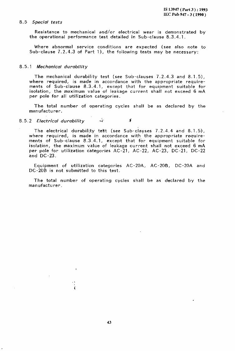
TABLE All
Rated making and breaking capacity conditions corresponding to several utilization categories
Make and break conditions
Util- ization ?/I, "rNe co5 @ On-time Off-time Number of
ategory operating
cycles (51 (21 (51
AC-2 4.0 1.05 0.65 0.05 (31 50
AC-3L51 8.0 1.05 (1) 0.05 (31 50 AC-4(51 10.0 1.05 111 0.05 (31 50
L/R (msl
DC-3 4.0 1.05 2.5 0.05 13s 50(61 DC-5 4.0 1.05 15.0 0.05 (31 50(6)
& Ms$e conditions
Util- I/I, U/u 6s
coso On-time Off-time Number of
ization operating
ategory cycles
(5) (2) ,Lsl
AC-3 10 1.05(41 (11 0.05 10 50 AC-4 12 1.05141 (11 0.05 10 50
I = Current made. The making current is expressed in d.c. or a.c. r.m.s. symnatrical values but it is understood that for a.c. the peak value of the asymmetrical current corresponding to the power- factor of that circuit may assume a higher value.
I, = Current made and broken , expressed in d.c. or a.c. r.m.s.
symmetrical values.
*e = Rated operational current.
U = Applied voltage.
"r = Power frequency or d.c. recovery voltage.
"e = Rated operational voltage.
COSQ = Power-factor of test circuit.
L/R = Time-constant of test circuit.
Ill cos@ = 0.45 for Ie 2 100 A, 0.35 for Ie > 100 A.
12) Time may be less than 0.05 s provided that contacts are allowed to become properly seated before re-opening.
(3) See Table AIII.
(41 For U/U, a tolerance of +20% is accepted.
(51 The make conditions shall also be verified but may be combined with the make and break test if agreed by the manufacturer. The making current multiples are to be as shown for I/I and the breaking current as shown for 1,/I,. The off-time is PO be taken from TableiAIII.
(61 Twenty-five operating cycles with one polarity and twenty-five operating cycles with reverse polarity.
46
,

IS 13947 (Part 3 ) : 1993 IEC Pub 947 - 3 ( 1990 )
A7. ,2.4.2 Operational performance
TABLE AIII
Relationship between current broken I,
and off-time for the verification
of the rated making and breaking capacities
-
Current broken Ic
(A)
I s 100
100 < IC s 200 C
200 < Ic 5 300
300 < I I 400 C
400 < I S 4600 c
600 < I 5 ,,800
800 < Ic s 1 000 C
1 000 < I s 1 300 c
1 300 < I 5 1 600 C
1 600 < I C
Off-time
(s)
10
20
30
40
60 $
1, 80
100
140
180
240
The values of off-time may be reduced if agreed by the manu- factu rer.
Sub-clause 7.2.4.2 of Part 1 applies with the following additions:
Equipment shall be capable of making and breaking currents without failure under the conventional conditions stated in Table AIV for the required utilization categories and the number of operations indicated therein.
47
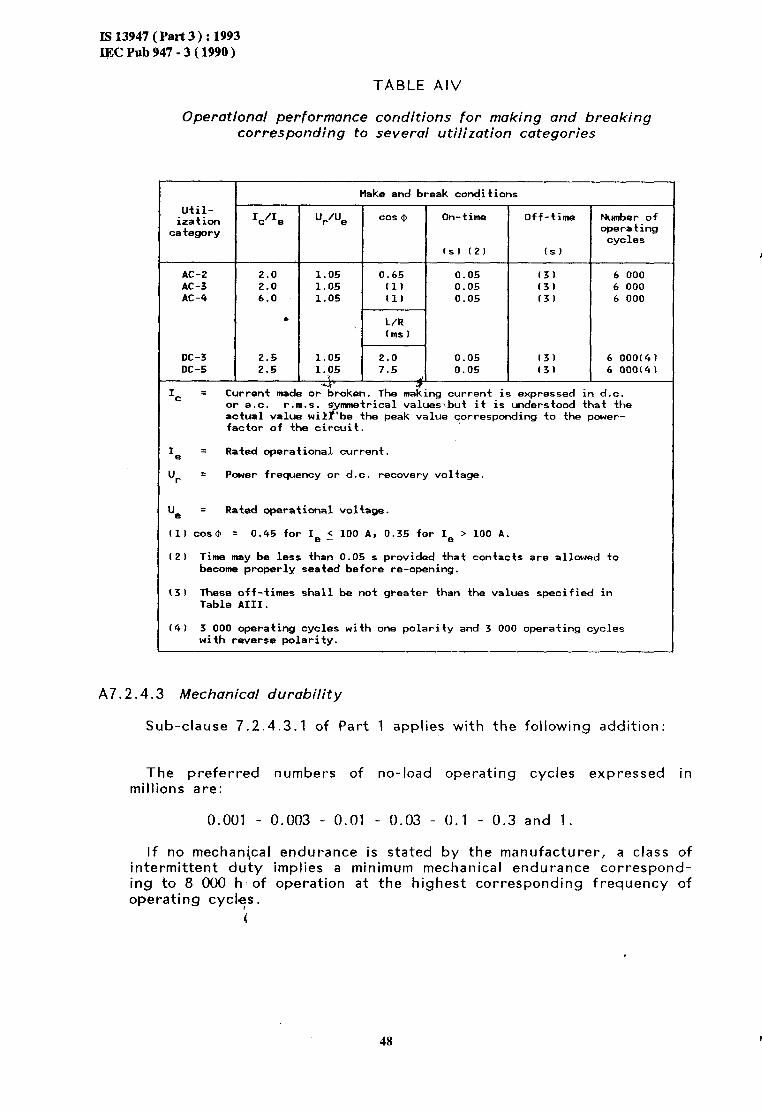
IS 13947 (Part 3 ) : 1993 IIX Pub 947 - 3 ( 1990 )
TABLE AIV
Operational performance conditions for making and breaking corresponding to several utilization categories
Util- ization
category
Off-time Number of operating cycles
AC-2 2.0 1.05 AC-3 2.0 1.05 AC-4 6.0 1.05
DC-3 2.5 1.05 DC-5 2.5 1.05
l
0.65 I11 (11 r L/R lmsl
2.0 7.5
I 0.05 (31 6 000 0.05 (31 6 000 0.05 (31 6 000
0.05 I31 6 OOO(4) 0.05 (31 6 OOO(41
rs; Ic = Current made or broken. The mazing current is expressed in d.c.
or a.c. r.m.s. 9' mmetrical values>.but it is understood that the actual value wik F be the peak value corresponding to the power- factor of the circuit.
Ie = Rated operational current.
ur = Power frequency or d.c. recovery voltage.
ue q Rated operational voltage.
(11 cos@ = 0.45 for Ie ( 100 A, 0.35 for Ie > 100 A.
(21 Time may be less than 0.05 s provided that contacts are allowed to become properly seated before re-opening.
(31 These off-times shall be not greater than the values specified in Table AIII.
(41 3 000 operating cycles with one polarity and 3 000 operating cycles with reverse polarity.
A7.2.4.3 Mechanical durability
Sub-clause 7.2.4.3.1 of Part 1 applies with the following addition:
The preferred numbers of no-load ‘operating cycles expressed millions are:
0.001 - 0.003 - 0.01 - 0.03 - 0.1 - 0.3 and 1.
If no mechanical intermittent duty ing to 8 000 h of operating cycles.
i
in
endurance is stated by the manufacturer, a class of implies a minimum mechanical endurance correspond- operation at the highest corresponding frequency of
48

is 13947 ( Part 3 ) : 1993 IEC Pub 947 - 3 ( 1990 )
A7.2.4.4 Electrical durability
Sub-clause 7.2.4.3.2 of Part 1 applies with the following addition:
The total number of on-load operating cycles shall be as declared by the manufacturer.
A8.3.3.3 Verification of making and breaking capacities
See Sub-clause 8.3.3.3 except that the test values shall be in accordance with Tables All and Alll.
A8.3.4,1 Operational performance test
See Sub-clause 8.3.4.1 except that the test conditions shall be in accordance with Table AIV.
A8.5 Special tests & $
Resistance to mechanical and/or ele.ctrical ,.wear is demonstrated by the operational performance teSk detailed in Sub-clause A8.3.4.1.
Where abnormal service conditions are expected (see also note to Sub-clause 7.2.4.3 of Part 1) the following tests may be necessary:
A8.5.1 Mechanical durability test
A8.5.1.1 Condition of the equipment for tests
The equipment shall .be installed as for normal service; in particular, the conductors shall be connected in the same manner as for normal use.
During the test there shall be no voltage or current in the main circuit. The equipment may be lubricated before the test if lubrication is prescribed in normal service.
A8.5.1.2 Operating conditions
The equipment shall be operated as in normal service.
A8.5.1.3 Test procedure
bl
The tests are carried out at the frequency of operations corre- sponding to the class of intermittent duty. However, if the manu- facturer considers that the equipment can satisfy the required conditions when using a higher frequency of operations, he may do so. i
The number of ,pperating cycles to be carried out shall be not less than the number of no-load operating cycles stated by the manu- facturer.
49

Is 13947 (Part 3) : 1993 IEC Pub 947 - 3 ( 1990 )
c) After each tenth of the total number of operations has been carried out, it is permissible before carrying on with the test:
to clean the whole equipment without dismantling;
to lubricate parts for which lubrication is prescribed by the manufacturer for normal service;
to adjust the travel and the pressure of the contacts if the design of the equipment enables this to be done.
d) This maintenance work shall not include any replacement of parts.
A8.5.1.4 Results to be obtained
Following the tests of mechanical durability, the equipment shall still be capable of complying *with the normal operating conditions at room temperature. There sh?#l be no loosening of the parts used for connecting the conductorg;. \,
A8.5.2 Electrical durability test
With respect to its resistance to electrical wear, an equipment is, by convention, characterized by the number of on-load operating cycles, corresponding to the different utilization categories given in Table AV which can be made without repair or replacement.
In all cases, the speed and number of operating cycles shall be chosen by the manufacturer.
The tests shall be taken as valid if the values recorded in the test report differ from the values specified only within the tolerances stated in Sub-clause 8.3.2.2.2 of Part 1.
Tests shall be carried out with the equipment under the appropriate conditions of Sub-clauses A8.5.1 .l and A8.5.1.2 using the test pro- cedure, where applicable, of Sub-clause A8.5.1.3, except that replace- ment of contacts is not permitted.
After the test, the equipment shall fulfil the normal operating
conditions and withstand a dielectric test voltage of twice the rated
operational voltage U,, but not less than 900 V, applied only as specified in Sub-clause 8.3.3.2.2 items a)1 and a)2.
IO
IS 13947 ( Part 3 ) : 1993 IEC Pub 947 - 3 ( 1990 )
TABLE AV
Verification of the number of on-load operating cycles Conditions for making and breaking
corresponding to several utilization categories
Util- value of the Make Break
ization rated operational category current I/I, u/u, coso Ic'Ie "Pe cos@
(1) (1)
AC-Z All values 2.5 1 0.65 2.5 1 0.65
AC-3 I, 5 17A 6 1 0.65 1 0.17 0.65
Ie > 176 6 1 0.35 1 0.17 0.35
AC-4 Ie 5 17A 6 1 0.65 6 1 0.65
I, > 17A 6 1 0.35 6 1 0.35
I/I, u/u, L/R (2) (ms)
v, “t-‘“e L/R (2) (ms)
DC-3 All values c,, 2.5 1 2 2.5 1 2
DC-5 All values 2.5 1 7.5 2.5 1 7.5
Ie = Rated operational current.
"e = Rated operational voltage.
I = Current made. In a.c. the conditions for making are expressed in r.m.s. symmetrical values but it is understood that the peak value of asymmetri- cal current, corresponding the power-factor of the circuit, may assume a higher value.
U = Applied voltage.
"r = Power frequency and d.c. recovery voltage.
I, = Current broken.
(11 Tolerance for cos@ : 20.05.
(21 Tolerance for L/R : 215%.
51

IS 13947 (Part 3 ) : 1993 IEC Pub 947 - 3 ( 1990 )
APPENDIX B
CLEARANCES AND CREEPAGE DISTANCES
Bl. General
Bl. 1 Suitable values for clearances great extent on variable factors type of insulation employed,- the .
and creepage distances depend, to a such as atmospheric conditions, the
disposition of the creepage paths and conditions of the system in which the equipment is to be used. For these reasons, the selection of the proper values. is the responsibility of the manufacturer.
B1.2 It is recommended that the surface of the insulating parts should be designed with ridges so arranged as to break the continuity of conduc- tive deposits which may form.
4 P
B1.3 Conductinq parts cover4 only with varnish or enamel, or protected
Bl
_ . only by oxidation or a similar process, should not be considered as being insulated from the point of v’iew of clearances .and creepage distances.
4 Clearances and creepage distances shall be maintained under the following circumstances:
al
bl
cl
On the one hand, without external electrical connections, and on the other hand, when conductors, either insulated or bare, of the type and of any dimensions specified for the equipment, are inst- stalled according to the ‘manufacturer’s instructions, if .any.
After interchangeable parts have been changed, taking into account maximum permissible manufacturing tolerances.
Taking into consideration possible deformations either due to the effect of temperature, ageing, shocks, vibrations or due to short-circuit conditions which the equipment is intended to endure.
82. Determination of c’learances and creepage distances
In determining clearances and creepage distances, it is recommended that the following points be considered:.
B2.1 In determining creepage distances, grooves at least 2 mm wide and 2 mm deep are measured along their contour. Grooves having any dimension less than these dimensions and any groove liable to be clogged with dirt are neglected and only the direct distance is measured. *’
i
52
. . . .
‘a.
._ ., .
..‘.+_. . . . :..,’ : IS 13947 (Part 3 ) : 1993 IEC Pub 947 - 3 ( 1990 )
B2.2 I n determining creepage distances, ridges less than 2 mm high are neglected. Those at least 2 mm high:
are measured along their contour, if they are an integral part of a component in insulating material (for instance by moulding or welding) ;
are measured along the shorter of two paths: length of joint or profile of ridge, if they are not integral parts of a component in insulating material.
B2.3 The application of the foregoing recommendations is illustrated by examples 1 to 11 of Appendix G of Part 1.
4
53

. .
IS13947(Part3):1993
IECPub947-3(1990)
APPENDIX C
ITEMS SUBJECT TO AGREEMENT BETWEEN MANUFACTURER AND USER
Note. - For the purpose of this appendix:
"agreement" is used in a very wide sense;
"user" includes testing stations.
Appendix J of Part 1 applies with regard to clauses and sub-clauses of this standard, with the following additions:
Clause or - sub-clause number
of this standard
4.4
7.1.6.1 Note
Switching 6f capacitors or of tungsten filament lamps
Operating time of auxiliary contacts provided for inter- locking
7.2.4.2 Increase of the operating rate for the verification of and Table IV the operational performance
8.3.3.1 Time interval greater than 30 s + 10 s between close-open cycles for making and breaking capacity test of equipment of Ith > 400 A
8.3.3.3.3
8.3.5.2.3
Appendix A A4.4
Table AI
.$ I tern
For categories AC-23A and AC-23B testing of making and breaking capacities by make cycles at 10 I the same number of make-break cycles at 8 Be
followed by
Verification of making and breaking capacities for utilization categories DC-22 and DC-23: replacement of the load of the test circuit by a motor
A.c. test circuit calibration for the short-circuit making capacity test in the case of d.c. equipment
Utilization categories other than those listed in Table AI1
Switching of rotor circuits
54

PIureai~ of Indian Standards
BIS is a statutory institution established under the Bureau of Indian Standards Act, 1986 to promote harmonious development of the activities of standardization, marking and quality certification of goods and attending to connected matters in the country.
Copyright
BIS has the copyright of all its publications. No part of these publications may be reproduced in any form without the prior permission in writing of BIS. This does not preclude the free use, in the course of implementing the standard, of necessary details, such as symbols and sizes, type or grade designalions. Enquiries relating to copyright be addressed to the Director (Publication), BIS.
Review of Indian Standards !
Amendments are issued to standards as the need arises on the basis of comments. Standards are also reviewed periodically; a standard along with amendments is reaffirmed when such review indicates that no changes are needed; if the review indicates that changes are needed, it is taken up for revision. Users of Indian Standards should ascertain that they are in possession of the latest amendments or edition by referring to the latest issue of ‘BIS Handbook’ and ‘Standards Monthly Additions’.
This Indian Standard has been developed fro-m Dot: No. ET17 (3496)
Amend&nts Issued Since P‘bblication
Amend No. Date of Issue Text Affected
BUREAU OF INDIAN STANDARDS Headquarters:
Manak Bhavan, 9 Bahadur Shah Zafar Marg, New Delhi 110002 Telephones: 323 0131,323 33 75,323 94 02
Regional Offices:
Central : Manak Bhavan, 9 Bahadur Shah Zafar Marg NEW DELHI 110002
Eastern : l/14 C.I.T. Scheme VII M, V.I.P. Road, Maniktola CALCUTTA 700054
Northern : SC0 335336, Sector 34-A, CHANDIGARH 160022
Southern : C.I.T. Campus, IV Cross Road, CHENNAI 600113
Western : Manakalaya, E9,MIDC, Marol, Andheri (East) MUMBAI 400093
Branches : AHMADAI~AD. BANGALORE. BHOPAL. BHUBANESHWAR. COIMBATORh. FARIDABAD. GHAZIABAD. GUWAHATI. HYDERABAD. JAIPUR. KANPUR. LUCKNOW. NAGPUR. PATNA. PUNE. THIRUVANANTHAPU,RAM.
Telegrams: Manaksanstha (Common to all offices)
Telephone
323 76 17,323 38 41
{ 337 337 84 86 99,337 26,337
85 9120 61
{ 60 60 38 20 43 25
{ 235 235 02 15 16,235 19,235 04 23 42 15
{ 832 832 92 78 95,832 91,832 78 78 58 92
Printed at Dee Kay Pripers, New Delhi, India