Embed Size (px)
Citation preview
Specification – MV Switchboard
Standard Number: HPC-8DJ-23-0001-2013

DM# 3698380 Page 2 of 88 Print Date 21/01/2014
© Horizon Power Corporation – Document Number: HPC-8DJ-23-0001-2013
Uncontrolled document when printed. Printed copy expires one week from print date. Refer to Document No. for current version.
Document Control
Author Name: Viswa Easwaran
Position: Standards Engineer
Document Owner
(May also be the Process Owner)
Name: Justin Murphy
Position: Manager Asset Management Support
Approved By * Name: Justin Murphy
Position: Manager Asset Management Support
Date Created/Last Updated January 2014
Review Frequency ** 5 yearly
Next Review Date ** January 2019
* Shall be the Process Owner and is the person assigned authority and responsibility for managing the whole process, end-to-end, which may extend across more than one division and/or functions, in order to deliver agreed business results.
** Frequency period is dependent upon circumstances– maximum is 5 years from last issue, review, or revision whichever is the latest. If left blank, the default shall be 1 year unless otherwise specified.
Revision Control
Revision Date Description
0 21/01/2014 First Issue
STAKEHOLDERS The following positions shall be consulted if an update or review is required:
Manager Engineering Services
Manager Capacity Management Support
Manager Asset Management Support
DM# 3698380 Page 3 of 88 Print Date 21/01/2014
© Horizon Power Corporation – Document Number: HPC-8DJ-23-0001-2013
Uncontrolled document when printed. Printed copy expires one week from print date. Refer to Document No. for current version.
TABLE OF CONTENTS
1 SCOPE ......................................................................................................... 6
2 NORMATIVE REFERENCES ....................................................................... 6
2.1 Standards ............................................................................................................... 6
2.2 Definitions and Abbreviations ................................................................................. 7
2.2.1 Definitions .......................................................................................................................... 7
2.2.2 Abbreviations ..................................................................................................................... 8
3 REQUIREMENTS ......................................................................................... 8
3.1 Power System Particulars ....................................................................................... 8
3.1.1 Design Fault Levels ........................................................................................................... 8
3.1.2 Nominal System Frequency ............................................................................................... 8
3.1.3 System Insulation Levels ................................................................................................... 9
3.1.4 Standard Operating Conditions .......................................................................................... 9
3.1.5 Clearances & Insulation ..................................................................................................... 9
3.1.6 Dimensions ...................................................................................................................... 10
4 SWITCHBOARD DESIGN AND CONSTRUCTION ................................... 10
4.1 General Requirements.......................................................................................... 10
4.1.1 Partition Class ................................................................................................................. 10
4.1.2 Loss of Service Continuity ................................................................................................ 10
4.2 Switchboard Layout .............................................................................................. 11
4.2.1 Rated Parameters and Performance ................................................................................ 11
4.2.2 Enclosure ........................................................................................................................ 11
4.2.3 Compartments ................................................................................................................. 11
4.2.3.1 General Requirement ..................................................................................................................... 11
4.2.3.2 Doors ............................................................................................................................................ 12
4.2.4 Shutters ........................................................................................................................... 13
4.2.5 Fixing of Equipment on Side Walls ................................................................................... 13
4.2.6 Venting ............................................................................................................................ 13
4.2.6.1 Internal Arc Classification (IAC) ...................................................................................................... 13
4.2.6.2 Explosion Relief Chamber and Ducting ........................................................................................... 14
4.2.7 Earthing ........................................................................................................................... 14
4.2.7.1 Earthbar ........................................................................................................................................ 14
4.2.7.2 Accessory Earthing ........................................................................................................................ 14
4.2.7.3 Circuit Breaker Earthing ................................................................................................................. 15
4.2.7.4 Cable Earthing ............................................................................................................................... 15
4.2.7.5 Bus Duct Earthing .......................................................................................................................... 15
4.2.7.6 Earthing Switches .......................................................................................................................... 15
4.2.8 Interlocks ......................................................................................................................... 16
4.2.9 Busbars and Primary Connections ................................................................................... 17

DM# 3698380 Page 4 of 88 Print Date 21/01/2014
© Horizon Power Corporation – Document Number: HPC-8DJ-23-0001-2013
Uncontrolled document when printed. Printed copy expires one week from print date. Refer to Document No. for current version.
4.2.10 Cable Termination............................................................................................................ 18
4.2.10.1 Cable Glands................................................................................................................................. 18
4.2.11 Current Transformers ....................................................................................................... 18
4.2.12 Voltage Transformers ...................................................................................................... 19
4.2.13 Rating Plates and Designation Labels .............................................................................. 19
4.2.14 Painting ........................................................................................................................... 20
4.3 Circuit Breaker ...................................................................................................... 20
4.4 Auxiliary Equipment .............................................................................................. 20
4.4.1 Auxiliary Equipment Compartment ................................................................................... 20
4.4.2 General Requirements for Control Circuit Elements.......................................................... 21
4.4.3 Wiring .............................................................................................................................. 21
4.4.3.1 General ......................................................................................................................................... 21
4.4.3.2 Secondary Wiring .......................................................................................................................... 22
4.4.4 General Protection Control Requirements ........................................................................ 22
4.4.4.1 General ......................................................................................................................................... 22
4.4.4.2 Protection Relay ............................................................................................................................ 23
4.4.4.3 Trip and Control Relays ................................................................................................................. 23
4.4.4.4 Trip Supply Supervision ................................................................................................................. 23
4.4.4.5 Trip Circuit Wiring and Supervision ................................................................................................. 24
4.4.4.6 Non Operation for Interruption / Restoration of Measuring or Trip Supplies ...................................... 24
4.4.4.7 Arc Detection Protection System Equipment ................................................................................... 24
4.4.4.8 Masking of Alarm Conditions .......................................................................................................... 25
4.4.4.9 Pre-wired Lead Supervision ........................................................................................................... 25
5 ELECTRICAL TESTS................................................................................. 25
5.1 General ................................................................................................................ 26
5.1.1 Manufacturer’s Testing Capabilities .................................................................................. 26
5.1.1.1 Witnessing of Tests ....................................................................................................................... 26
5.1.1.2 Test instruments and Apparatus ..................................................................................................... 27
5.1.1.3 Test Certificates............................................................................................................................. 27
5.2 Type Tests............................................................................................................ 27
5.2.1 Routine Tests .................................................................................................................. 27
5.2.1.1 Switchgear .................................................................................................................................... 27
5.2.1.2 Current and Voltage Transformers ................................................................................................. 28
5.2.1.3 Insulation Tests ............................................................................................................................. 28
5.2.2 Tests Prior to Completion of Defects Liability Period......................................................... 28
6 STORAGE .................................................................................................. 28
7 RELIABILITY .............................................................................................. 28
8 ENVIRONMENTAL CONSIDERATIONS ................................................... 28
9 DOCUMENTATION .................................................................................... 29
9.1 Type Test Certificates/Reports ............................................................................. 29

DM# 3698380 Page 5 of 88 Print Date 21/01/2014
© Horizon Power Corporation – Document Number: HPC-8DJ-23-0001-2013
Uncontrolled document when printed. Printed copy expires one week from print date. Refer to Document No. for current version.
10 PACKAGING REQUIREMENTS ................................................................ 29
11 SPARE EQUIPMENT ................................................................................. 29
APPENDIX A – ADDITIONAL REQUIREMENTS ............................................................................................. 30
A.1 Current Transformers ..................................................................................................................... 30
A.2 Voltage Transformers .................................................................................................................... 30
A.3 Circuit Breaker ............................................................................................................................... 31
A.4 General Requirements for Control Circuit Elements ........................................................................ 37
A.5. Secondary Wiring .......................................................................................................................... 41
APPENDIX B – REVISION INFORMATION ..................................................................................................... 44
APPENDIX C – QUALITY ASSURANCE (TO BE COMPLETED BY STORES) ................................................. 45
APPENDIX D – TECHNICAL SCHEDULES A & B FOR EQUIPMENT .............................................................. 47
D.1 Standard panel configuration for switchboards ........................................................................................... 47
D.2 Technical Schedule for 22 kV switchboard operating at 11/ 6.6 kV ............................................................. 48
D.3 Technical Schedule for 22 kV switchboard operated at 22 kV ..................................................................... 56
D.4 Technical Schedule for 33 kV switchboard operated at 33 kV ..................................................................... 64
APPENDIX E – COMPLIANCE DOCUMENT ................................................................................................... 71
APPENDIX F – DEPARTURES FROM TECHNICAL SPECIFICATION............................................................. 75
APPENDIX G – MISCELLANEOUS INFORMATION ........................................................................................ 76

DM# 3698380 Page 6 of 88 Print Date 21/01/2014
© Horizon Power Corporation – Document Number: HPC-8DJ-23-0001-2013
Uncontrolled document when printed. Printed copy expires one week from print date. Refer to Document No. for current version.
1 SCOPE
This specification covers Horizon Power's requirements for new factory-assembled medium voltage (MV) switchboard including circuit breakers, instrument transformers, protection relays, auxiliary equipment and circuitry for rated voltages from 6.6 kV up to and including 33 kV.
Tests prescribed will evaluate the performance of the switchgear, and shall comply with this specification.
Approval in terms of this specification shall be obtained by one or a combination of the following:
a) successful completion of the appropriate tests required by this specification by an independent and accredited test authority.
b) provision of test certificates from an independent and accredited test authority based upon an alternative specification, with test requirements at least equivalent to this specification.
NOTE: Verification of accreditation of the test authority shall be provided by NATA (National Association of Testing Authorities) accredited test house or by a test house possessing accreditation from a NATA MRA (Mutual Recognition Agreement) partner.
2 NORMATIVE REFERENCES
2.1 Standards
The following documents contain provisions that, through reference in the text, constitute requirements of this specification. At the time of publication, the editions indicated were valid. All standards and specifications are subject to revision, and vendors are encouraged to investigate the possibility of applying the most recent editions of the documents listed below. Information on currently valid national and international standards and specifications can be obtained from SAI Global – Standards On-Line data base or equivalent standards database.
Table 1: List of Applicable Standards -
STANDARD DESCRIPTION
AS 1125 Conductors in insulated electric cables and flexible cords
AS 2312-2002 (incl. Amdt 1:2004)
Guide to the protection of structural steel against atmospheric corrosion by the use of protective coatings
AS 1824.1-1995 (incl. Amdt.1-
1997)
Insulation coordination: Part 1 – Definitions, principles, and rules
AS 1931.1 High voltage testing techniques
Part 1 - General definitions and test requirements
DM# 3698380 Page 7 of 88 Print Date 21/01/2014
© Horizon Power Corporation – Document Number: HPC-8DJ-23-0001-2013
Uncontrolled document when printed. Printed copy expires one week from print date. Refer to Document No. for current version.
STANDARD DESCRIPTION
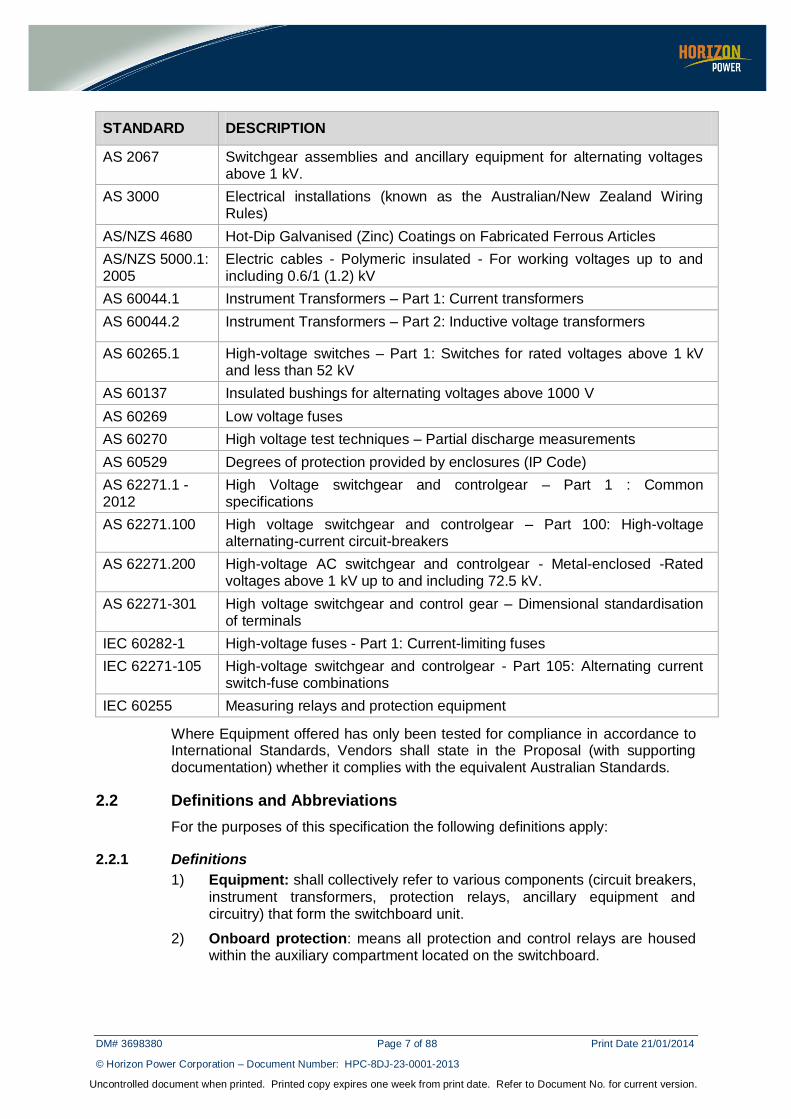
AS 2067 Switchgear assemblies and ancillary equipment for alternating voltages above 1 kV.
AS 3000 Electrical installations (known as the Australian/New Zealand Wiring Rules)
AS/NZS 4680 Hot-Dip Galvanised (Zinc) Coatings on Fabricated Ferrous Articles
AS/NZS 5000.1:2005
Electric cables - Polymeric insulated - For working voltages up to and including 0.6/1 (1.2) kV
AS 60044.1 Instrument Transformers – Part 1: Current transformers
AS 60044.2 Instrument Transformers – Part 2: Inductive voltage transformers
AS 60265.1 High-voltage switches – Part 1: Switches for rated voltages above 1 kV and less than 52 kV
AS 60137 Insulated bushings for alternating voltages above 1000 V
AS 60269 Low voltage fuses
AS 60270 High voltage test techniques – Partial discharge measurements
AS 60529 Degrees of protection provided by enclosures (IP Code)
AS 62271.1 - 2012
High Voltage switchgear and controlgear – Part 1 : Common specifications
AS 62271.100 High voltage switchgear and controlgear – Part 100: High-voltage alternating-current circuit-breakers
AS 62271.200 High-voltage AC switchgear and controlgear - Metal-enclosed -Rated voltages above 1 kV up to and including 72.5 kV.
AS 62271-301 High voltage switchgear and control gear – Dimensional standardisation of terminals
IEC 60282-1 High-voltage fuses - Part 1: Current-limiting fuses
IEC 62271-105 High-voltage switchgear and controlgear - Part 105: Alternating current switch-fuse combinations
IEC 60255 Measuring relays and protection equipment
Where Equipment offered has only been tested for compliance in accordance to International Standards, Vendors shall state in the Proposal (with supporting documentation) whether it complies with the equivalent Australian Standards.
2.2 Definitions and Abbreviations
For the purposes of this specification the following definitions apply:
2.2.1 Definitions
1) Equipment: shall collectively refer to various components (circuit breakers,
instrument transformers, protection relays, ancillary equipment and circuitry) that form the switchboard unit.
2) Onboard protection: means all protection and control relays are housed within the auxiliary compartment located on the switchboard.

DM# 3698380 Page 8 of 88 Print Date 21/01/2014
© Horizon Power Corporation – Document Number: HPC-8DJ-23-0001-2013
Uncontrolled document when printed. Printed copy expires one week from print date. Refer to Document No. for current version.
3) Off board protection: means all protection and control relays and
associated circuitry are housed away from the front of the switchboard in a separate room.
2.2.2 Abbreviations
1) AS: Australian Standard
2) CB: Circuit Breaker
3) CT: Current Transformer
4) IAC: Internal Arc Classification
5) kV: kilo Volts (1,000 volts)
6) LED: Light Emitting Diode
7) LV: Low Voltage <1000 volts AC
8) MV: Medium Voltage >1000 volts AC; <36 000 volts AC
9) MVAr: Mega Volt Amp reactive (1,000,000 Volt Amp reactive)
10) MW: Mega Watts (1,000,000 Watts)
11) pf: power factor
12) SCADA: Supervisory Control and Data Acquisition
13) VT: Voltage Transformer
3 REQUIREMENTS
3.1 Power System Particulars
The Equipment shall be suitable for continuous connection to a power system with the characteristics covered below.
3.1.1 Design Fault Levels
The Maximum short circuit withstand currents are as follows:
North West Interconnected System:
1) 16 kA rms / 3 second for 33 kV systems
2) 25 kA rms / 3 second for 22, 11 kV and 6.6 kV systems
Non Interconnected System:
Individual fault levels vary for the different networks. The short circuit fault requirement will be specified in Schedule A of the document (see note below).
NOTE: Most vendors offer standard equipment with a minimum fault level of
16 kA for 22 kV and 33 kV. For systems with very low fault current, it is recommended to use the 16 kA rated equipment. This is to avoid separate type testing costs associated with a lower fault rated equipment.
3.1.2 Nominal System Frequency
The nominal system frequency is 50 Hz.

DM# 3698380 Page 9 of 88 Print Date 21/01/2014
© Horizon Power Corporation – Document Number: HPC-8DJ-23-0001-2013
Uncontrolled document when printed. Printed copy expires one week from print date. Refer to Document No. for current version.
3.1.3 System Insulation Levels
The system Basic Impulse Insulation Levels (BIL) are as follows:
Table 2: System Insulation Levels
Nominal System Voltage (kV rms)
System Highest Voltage (kV peak)
Lightning Impulse withstand Voltage (kV peak)
Power Frequency withstand Voltage (kV peak)
6.6 7.2 60 20
11.0 12.0 75 28
22.0 24.0 125 50
33.0 36.0 170 70
Equipment rated at 24 kV (Does not apply to VT’s) need to be capable of being continuously operated at 6.6 kV and 11 kV nominal voltages without any restrictions. If any extra provisions are required for 24 kV rated Equipment to be operated at 6.6 kV or 11 kV, details of such shall be provided by the Vendor in the Proposal.
3.1.4 Standard Operating Conditions
The Equipment shall be suitable for continuous operation under the service conditions for indoor switchgear as per AS 62271.1 with the following additions:
Table 3: Additional Operating Requirements
Condition Requirement
Maximum and Minimum
Air temperatures
55°C maximum –5°C minimum
Vendors shall submit with the Proposal, documentation (evidence, test reports, etc.) to demonstrate that the Equipment offered meets the environmental service conditions. Vendors shall clearly state in the Proposal, any Equipment that does not meet the environmental service conditions and provide the maximum environmental service conditions the Equipment if capable of withstanding.
3.1.5 Clearances & Insulation
The minimum electrical clearance in air to earth for all high voltage parts of the Equipment shall be not less than that specified in AS 2067-2008.
Vendors that offer Equipment with cast resin (or similar material) encapsulated current carrying MV conductors shall provide test reports to demonstrate that the cast resin or similar material shall not be affected by the operation of the Equipment under the service conditions detailed in this Specification. In particular, load cycling due to the different coefficient of expansion of the metallic conductor and the insulation material at different temperatures over time.

DM# 3698380 Page 10 of 88 Print Date 21/01/2014
© Horizon Power Corporation – Document Number: HPC-8DJ-23-0001-2013
Uncontrolled document when printed. Printed copy expires one week from print date. Refer to Document No. for current version.
3.1.6 Dimensions
Preference shall be given to equipment having dimensions that do not exceed the maximum height of 2300 mm for 24 kV and 36 kV Equipment.
In addition, the switchgear must also meet the dimension requirements for specific compartments as described in the different sections of this specification.
NOTE: The height of the equipment does not include the explosion exhaust
chamber/ducts that may be installed for arc venting purposes.
4 SWITCHBOARD DESIGN AND CONSTRUCTION
4.1 General Requirements
The complete switchgear shall be of a metal clad design in accordance with AS 62271.1 and AS 62271.200-2005.
All circuit breakers shall be fully withdrawable. Fixed breakers shall be considered however Horizon Power will evaluate the information and make a determination to accept or reject the proposal.
Oil shall not be used either as an insulating or interrupting medium. Air blast circuit breakers shall not be accepted.
The switchgear will be complete with circuit breakers, protection relays, ancillary equipment and circuitry as defined by the specification.
The vendor shall ensure that the switchgear is designed to readily facilitate installation without the need for special blanking plates, fittings, temporary secondary wiring arrangements or other accessories.
4.1.1 Partition Class
The switchgear shall adhere to partition class PM. All open compartments must be surrounded by earthed metallic partitions and/or metallic shutters.
4.1.2 Loss of Service Continuity
The switchgear must comply with category LSC2B as defined by AS 622671.200. When any accessible compartment in a functional unit is open, all other functional units must remain energized and operate normally. Access to individual compartments shall be such that work may be carried out safely in that compartment while all other adjacent circuits are in service.
Trained and authorized persons shall be able to carry out the following operations on energised switchboard, without danger of direct contact with live parts:
1. control and reset of relays and disconnecting switch, inspection of signalling devices and instruments;
2. working and testing with breaker in test / service condition;
3. replacement of auxiliary fuses, lamps, and.;

DM# 3698380 Page 11 of 88 Print Date 21/01/2014
© Horizon Power Corporation – Document Number: HPC-8DJ-23-0001-2013
Uncontrolled document when printed. Printed copy expires one week from print date. Refer to Document No. for current version.
4. voltage, current measurements and location of failures, carried out with the proper instruments adequately insulated.
4.2 Switchboard Layout
4.2.1 Rated Parameters and Performance
The Equipment shall meet the rated parameters specified in Appendix D Schedule A included with this document.
4.2.2 Enclosure
The entire switchboard enclosure shall be free standing, floor mounted and be designed to ensure maximum safety during all operation conditions, inspection and or maintenance activities. Vertical units shall be assembled to form a continuous line up of uniform height and depth.
It shall be possible to bolt the structure of the switchboard to beams, which are cast-in or are part of the station floor.
The design of the switchboard and control gear assembly shall make it possible to install extension panels at either end without shutting down the switchgear until bus bar connection is required. Extension shall be possible without the need to drill holes in the connecting surfaces or in the structural frame. Ends of bus bars shall be suitably modified for this purpose.
The enclosure covering plates shall be fixed such that an internal explosion shall never cause any movement of these plates. Removable cover plates shall be fixed with bolted connections only. Any other construction using ‘’hook on’’ or fixing by means of swivels is not acceptable. When removing bolted panels, it shall not be necessary to first gain access behind the panels to hold bolts or nuts. The weight of the panel should not have to be relieved from the bolts when loosening them.
The switchgear and control gear panel shall have a minimum degree of ingress protection IP52. If necessary, opening for natural ventilation / exhaust ducting
shall be provided. These shall be louvered with wire mesh. However the IP rating shall not be affected due to this.
Suitable eye bolts for lifting of panel shall be provided. If eyebolts are removable caps shall be provided to seal any opening on the surface of the switchboard.
4.2.3 Compartments
4.2.3.1 General Requirement
The switchgear shall be made up of individual switchgear panels. The individual switchgear panels shall be fully segregated into four compartment types as follows:
1) The main switching devices that is the circuit breakers;
2) Components connected to one side of the main switching device, which is the external cable circuit and current transformers;
3) Components connected to the other side of the main switching device, that is the busbars; and

DM# 3698380 Page 12 of 88 Print Date 21/01/2014
© Horizon Power Corporation – Document Number: HPC-8DJ-23-0001-2013
Uncontrolled document when printed. Printed copy expires one week from print date. Refer to Document No. for current version.
4) Auxiliary equipment compartment to house Control and Protection equipment (on-board protection) or Indication circuits (off-board protection), (Section 4.4 for details) etc.
Compartments shall be of a fabricated, rigidly braced, structural steel framework. Where compartment walls or doors have cut-outs for the mounting of Protection, Control and Supervisory equipment, the thickness of sheet shall be increased or stiffeners provided to maintain panel rigidity equivalent to the uncut sheet, if required.
The compartmenting shall be designed so that the separation between the adjacent busbar, and or circuit breaker/ starter, and or the cable termination compartment is retained when the circuit breaker is withdrawn.
Compartment for cable connection shall allow cable pulling, termination and connection work with switchgear energised. Vendor shall offer suitable method for access to rear covers.
The Auxiliary Equipment compartment shall be mounted directly above its associated circuit breaker compartment, and be accessible from the front of the switchboard. Particular attention should be taken to ensure that the protection relay does not foul the opening of the compartment.
Access to CT’s within compartments shall be easily accomplished by removing the bolted cover, it shall not be necessary to disconnect any of the primary or secondary cables to gain access.
4.2.3.2 Doors
Door seals shall comprise a neoprene or identical non sticking poly material section held in a metal channel on the door and compressed by a dished edge on the fixed enclosure, when the door is closed. All doors shall be equipped with a lockable latch; high doors shall have a dual latching system.
All doors shall be able to open to at least 120°, regardless of the status of adjacent doors, handles, levers or accessories.
Doors shall be provided with “stay bars” which positively locate them when open, and not foul wiring or equipment when closed.
All doors shall be hinged on the left side of their associated compartment. Doors greater than 1200 mm high shall have three hinges.
In addition the circuit breaker doors shall comply with the following requirements:
1) Access to any equipment, items, locks, levers or devices associated with circuit breaker carriage racking operations shall be accessible from the front or right hand side of the breaker carriage. That is, with the door open and located to the left side of the carriage, the operator shall enjoy complete freedom of access to all items at the front and right hand side of the carriage.
2) The door, if removable shall have lift off chrome plated hinges and shall be designed to meet the requirements of Section 4.2.6.1 and interlock requirements of Section 4.2.8.
DM# 3698380 Page 13 of 88 Print Date 21/01/2014
© Horizon Power Corporation – Document Number: HPC-8DJ-23-0001-2013
Uncontrolled document when printed. Printed copy expires one week from print date. Refer to Document No. for current version.
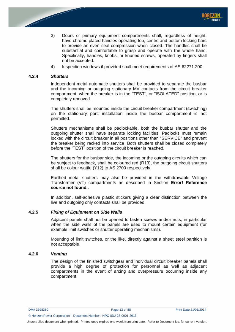
3) Doors of primary equipment compartments shall, regardless of height, have chrome plated handles operating top, centre and bottom locking bars to provide an even seal compression when closed. The handles shall be substantial and comfortable to grasp and operate with the whole hand. Specifically, handles, knobs, or knurled screws, operated by fingers shall not be accepted.
4) Inspection windows if provided shall meet requirements of AS 62271.200.
4.2.4 Shutters
Independent metal automatic shutters shall be provided to separate the busbar and the incoming or outgoing stationary MV contacts from the circuit breaker compartment, when the breaker is in the "TEST", or "ISOLATED" position, or is completely removed.
The shutters shall be mounted inside the circuit breaker compartment (switching) on the stationary part; installation inside the busbar compartment is not permitted.
Shutters mechanisms shall be padlockable, both the busbar shutter and the outgoing shutter shall have separate locking facilities. Padlocks must remain locked with the circuit breaker in all positions other than "SERVICE" and prevent the breaker being racked into service. Both shutters shall be closed completely before the ‘TEST” position of the circuit breaker is reached.
The shutters for the busbar side, the incoming or the outgoing circuits which can be subject to feedback, shall be coloured red (R13), the outgoing circuit shutters shall be colour wattle (Y12) to AS 2700 respectively.
Earthed metal shutters may also be provided in the withdrawable Voltage Transformer (VT) compartments as described in Section Error! Reference source not found..
In addition, self-adhesive plastic stickers giving a clear distinction between the live and outgoing only contacts shall be provided.
4.2.5 Fixing of Equipment on Side Walls
Adjacent panels shall not be opened to fasten screws and/or nuts, in particular when the side walls of the panels are used to mount certain equipment (for example limit switches or shutter operating mechanisms).
Mounting of limit switches, or the like, directly against a sheet steel partition is not acceptable.
4.2.6 Venting
The design of the finished switchgear and individual circuit breaker panels shall provide a high degree of protection for personnel as well as adjacent compartments in the event of arcing and overpressure occurring inside any compartment.

DM# 3698380 Page 14 of 88 Print Date 21/01/2014
© Horizon Power Corporation – Document Number: HPC-8DJ-23-0001-2013
Uncontrolled document when printed. Printed copy expires one week from print date. Refer to Document No. for current version.
4.2.6.1 Internal Arc Classification (IAC)
The switchgear shall be designed to conform with the requirements of arc-fault venting in accordance with AS 62271.200 Annex A.2 Accessibility Type A.
Operators of the Equipment shall be protected against the effects of an arcing fault in any of the MV compartment at all times, including during any racking operations. Full arc containment shall be possible under these conditions.
The equipment must be designed to handle arc containment for the maximum design fault current as per Section 3.1.1 for a duration one (1) sec.
The Vendor shall provide in the Proposal the IAC accessibility type including sides (Front, Lateral & Rear) and internal arc current and duration with supporting test reports demonstrating IAC compliance. The equipment must meet all IAC test criteria as defined by AS 62271-200 (A-6).
4.2.6.2 Explosion Relief Chamber and Ducting
An explosion exhaust chamber shall be incorporated, such that the gases resulting from the internal arcing in the compartments always escape in a direction, away from the operator standing in front of switchboard. Each MV compartment shall have its own relief facility and designed such that the hot ionized gases from the compartments are directly conducted to the outside of the switchboard into the exhaust chamber, without reaching any other compartments of the switchboard. All relief valves shall be vermin proof.
The vendor shall make recommendation on the design of the explosion chamber. If the danger exists that gases of an internal explosion, released in the
switchroom space can harm the operator, for instance because of its limited dimensions, additional ducting shall be quoted for separately, to conduct the gases to the outside of the building. Vendor shall state when this facility is required, free height of ceiling, free space over and to the rear of the switchboard.
4.2.7 Earthing
All earthing must comply with the requirements as defined in AS 62271.1 and AS 62271.200 in addition to the following:
4.2.7.1 Earthbar
The completed switchgear shall have an earth bar with a minimum cross section of 40 mm x 5 mm and shall be rated to carry the maximum fault current running throughout the length of the switchboard. It must be made of hard drawn high conductivity copper and should have provision for a minimum of 4 connections to the distribution substation earth.
The earth bar shall not be insulated or be interrupted (interconnected). It shall have branches to all circuit breakers, starter units or and other main electrical equipment such as but not limited to: current transformers, earthing switches and the switchboard structure and enclosure itself.

DM# 3698380 Page 15 of 88 Print Date 21/01/2014
© Horizon Power Corporation – Document Number: HPC-8DJ-23-0001-2013
Uncontrolled document when printed. Printed copy expires one week from print date. Refer to Document No. for current version.
4.2.7.2 Accessory Earthing
All doors shall be grounded by means of a flexible, stranded copper wire (see Appendix G for wiring requirements), and connected to the stationary part of the switchboard. Earthing connections through the hinges are not acceptable.
Panel mounted equipment with exposed metal parts such as indicating lights, push buttons and relays shall be separately earthed.
Earth wiring connecting electrical equipment and exposed metal parts to the earth bar or metal enclosure frame shall be sized in accordance with AS 3000 in relation to the size of the largest active conductor.
All metal shutters shall be earthed to the earth bar of the switchboard, using a flexible connection which will not hamper the operating mechanism.
4.2.7.3 Circuit Breaker Earthing
The trucks of the circuit breakers shall have a direct connection with the earth bar, both in the test position and the fully engaged position, as well as during travelling to and from these positions.
All circuit breakers shall be grounded by means of a copper brush or sliding contact, which shall be mounted on the switchboard structure and connected to the earth bar.
The fixed earthing part shall be silver-plated to prevent corrosion.
4.2.7.4 Cable Earthing
An earthing strip of 25 mm x 5 mm size connected to the distribution substation earth bar shall be installed inside the cable compartment for earthing the cable screen and shall be insulated from the switchgear frame earth. It shall be clearly labelled as being the cable screen earthing bar. The switchboard shall be provided with one separated earthing screw for each cable to connect cable armour earthing where applicable.
4.2.7.5 Bus Duct Earthing
The structure of the bus duct shall be connected through a flexible braiding, having the same cross section as the main earth bar, to a copper branch of the main earth bar, having the same dimension as the main earth bar.
The connection point shall be at the connecting flange. The flexible braiding is part of the switchboard supply.
4.2.7.6 Earthing Switches
Each panel in the switchgear shall include a suitable fault making earthing device to earth its MV cable circuit and busbar. Vendors shall state clearly what types of earthing devices are proposed.
An earthing switch shall be capable of making the full short circuit current, the operating mechanism shall be charged spring operated in both directions.

DM# 3698380 Page 16 of 88 Print Date 21/01/2014
© Horizon Power Corporation – Document Number: HPC-8DJ-23-0001-2013
Uncontrolled document when printed. Printed copy expires one week from print date. Refer to Document No. for current version.
The operating mechanism of the earthing switch shall be accessible from the front only, with all doors or covers closed. Preferably access to operating shafts shall be prevented when the circuit breaker is closed, this to avoid damage to the interlocking mechanism.
The contacts of the earthing switch shall be directly connected through a copper connection with main earthing bar; the flexible braided conductor shall jump the shaft mechanism.
The earthing switch shall be interlocked mechanically with its upstream circuit breaker such that mutual inadvertent closing is impossible.
All earthing devices must either be capable of being viewed so that visible indication of earthing is given or indicating devices must be positively linked to the earth switch operating mechanism. The position of each earthing switch shall be visible from the front, without opening doors or covers. Two spare auxiliary switches shall be provided on each earthing device which can be used for remotely indicating the operating position of the earth switch. Each switch shall be wired out to the terminal block strip in the associated auxiliary equipment compartment.
If the circuit breaker is used to provide the earth connection it shall not be possible to trip the circuit breaker from a remote position whilst in the earthed position. Breakers used for earthing shall be manual trip only.
The earth switch shall be capable of at least two operations at rated fault-make current before repair or replacement becomes necessary. Each switch shall be capable of being locked with a padlock in either the open or closed position.
4.2.8 Interlocks
Interlock mechanisms shall be mechanical and manually operated. They shall be provided with permanently lasting labels which are readily visible and which contain clear and concise instructions to operators.
Interlocks shall be provided to prevent the following operations:
1) The truck portion from being withdrawn from or inserted into the “SERVICE” position when the circuit breaker is closed. Attempted withdrawal shall not trip a closed circuit breaker.
2) The closing of the circuit breaker unless the truck portion is correctly positioned in the selected location, or fully isolated or withdrawn from the equipment.
3) The circuit breaker being closed in the ‘SERVICE” position without completing the appropriate auxiliary circuits between the fixed portion and the circuit breaker truck.
4) The circuit breaker truck being plugged into the fixed portion unless it is correctly positioned.
5) Between the circuit breaker assembly and the control cable plug if required so that that the plug only can be removed in the test position of the circuit breaker and prevent moving of the circuit breaker to the engaged position without the plug locked in.

DM# 3698380 Page 17 of 88 Print Date 21/01/2014
© Horizon Power Corporation – Document Number: HPC-8DJ-23-0001-2013
Uncontrolled document when printed. Printed copy expires one week from print date. Refer to Document No. for current version.
6) The fault-make earthing switch from being closed unless the associated circuit breaker is in the “ISOLATED” position.
7) The circuit breaker from being closed while in the “SERVICE” position when its associated fault-make earthing switch is in the closed position.
8) The auxiliary circuits being disconnected with the circuit breaker closed in the “SERVICE” position.
9) The circuit breaker of a lower current rating from being inserted into the fixed portion of a higher normal current rating.
10) The fault-make earthing switch from being closed on a live busbar.
11) The front door (if applicable) of the circuit breaker compartment shall not be opened until the circuit breaker is in the “ISOLATED” position.
Vendors shall provide full details of Equipment interlocks. Interlock schemes which result in tripping of the circuit breaker while attempting an illegal operation are not preferred.
Interlock mechanisms shall function positively without the need to physically manipulate them to achieve the desired result.
Dead front protection shall be maintained throughout the withdrawal operation. Such interlocks shall not prevent the circuit breaker being fully functional in the “TEST” position.
4.2.9 Busbars and Primary Connections
The busbars shall be designed and constructed in accordance with AS 62271.1 and be of hard drawn, high conductivity copper of uniform cross section throughout the switchgear.
The busbar system includes the connections to and from the horizontal conductors and the incoming and the outgoing cables, both to or from the fixed contacts of the switching device.
Joints shall be bolted and have provision to maintain contact pressure. Busbars should be supplied complete with bridging pieces for connection of transportable sections and provision made to accommodate any thermal expansions. Bolted joints shall be silver surfaced; ring-plating will not be permitted. Bolts and associated hardware shall be of non-magnetic, corrosion-resistant material. Any busbar bolt holes shall be drilled. Punching shall not be accepted, as this is known to lead to point or line contacts and bus bar failure. All related fixing torques shall be indicated in the maintenance manual.
The busbar compartments shall be fitted with removable covers to provide access to busbars and joints at all circuit cubicle.
Primary busbar conductors and connections shall be covered with insulation material and coloured red R13 to AS 2700. Insulators for busbar supports shall be made of high quality non-hygroscopic insulating material, suitable to withstand the occurring dynamic forces. A soft rubber gasket shall be applied between the vertical sections of a busbar compartment.

DM# 3698380 Page 18 of 88 Print Date 21/01/2014
© Horizon Power Corporation – Document Number: HPC-8DJ-23-0001-2013
Uncontrolled document when printed. Printed copy expires one week from print date. Refer to Document No. for current version.
Materials shall be supplied for insulating the busbars at joints between compartment units separated for shipment. Busbars shall be arranged relative to the front of the switchgear top to bottom/left to right/back to front, as appropriate.
4.2.10 Cable Termination
All switchgear panels requiring MV cable terminations shall be fitted with cable boxes. The boxes shall be suitable for cable sizes specified in Appendix D-Schedule A of the document. Primary cables shall be separated from each other and from the cables of other circuits via barriers.
The cable boxes will be downward pointing. The dimensions of the cable box shall completely contain the cable termination. Vendor shall verify that the cable termination, made according to the installation instructions of its manufacturer, amply fits into the available cable termination space of the switchboard. The termination of cables is to be carried out by Horizon Power’s approved contractor.
The cable termination palms should preferably be 1 metre above floor level and suitable for connecting the cables which rise vertically from the switchroom cable trench below.
A metallic cable support system shall be provided to fix and support the weight of all incoming and outgoing cables within and on the outside of the switchboard.
They shall be fitted with an undrilled removable gland plate for each cable to allow the cables to be laid into and removed from the box without the need to thread the cables through the gland entry.
The cable box entry for single core cables shall be designed to minimise the possibility of eddy current heating.
Primary cable compartments shall be large enough to accommodate cable stress cones, and shall include cable connectors and cable supports.
For panels with more than one power cable termination, the set of terminals nearest to the circuit breaker shall be designated ‘A’ with the next set of terminals designated ‘B’ and ‘C’ if applicable. All terminals must comply with dimensions defined as per AS 62271-301.
4.2.10.1 Cable Glands
Where multiple cable glands are fitted to the cable box a minimum clear separation of 100 mm shall be maintained between glands. The minimum distance from the bottom of the cable gland to floor level shall be 300 mm. The gland plates are to have insulated cable glands to suit the cables specified and approved means of supporting the cables. There shall be no damages to the cable due to rough edges of the gland plate. Suitable rubber grommets shall be provided if this is the case.
Attention shall be paid to the insulation and earthing of the gland and the gland plate, if core balance earth fault protection is required. If single core cable or steel tape armour is applied, the cable gland shall be approved for use by Horizon Power.

DM# 3698380 Page 19 of 88 Print Date 21/01/2014
© Horizon Power Corporation – Document Number: HPC-8DJ-23-0001-2013
Uncontrolled document when printed. Printed copy expires one week from print date. Refer to Document No. for current version.
4.2.11 Current Transformers
Refer Appendix A1.
4.2.12 Voltage Transformers
Refer Appendix A2.
4.2.13 Rating Plates and Designation Labels
The rating plates shall be made of stainless steel and fixed to the surface by permanent fasteners. Adhesive fixing is not acceptable.
The rating information shall be engraved on the surface of the plates. Engraving shall be filled with non-deteriorating black paint. The maker’s rating plate shall be in accordance with AS 62771.200.
Main circuit labels shall be fixed to the front and rear of each switchgear unit. Such labels shall be approximately 240 mm x 75 mm with 25 mm black lettering on a white background. In addition, the Vendor shall fit an operating label 65 mm x 25 mm immediately above or below the circuit breaker control switch. The labels shall contain the circuit designations of the switchboard single line diagram.
VT marshalling boxes shall be labelled on the external surface of the door so as to clearly identify and associate it with the VT to which it is wired. The label shall include the associated bus bar name (e.g.) Front, Rear, A, B, as appropriate.
The Vendor shall provide and install labels adjacent to every item of equipment (e.g. relays, selector switches, fuses, links, MMLG Test Blocks, MCB’s, etc) which contain the circuit designation, function and such other details as may be relevant to facilitate identification from either side of the panel. These labels shall have black letters engraved on a white background, using white - black - white laminated engraving sheets.
Labels shall be fixed to the mounting plate using a suitable adhesive. Embossed, punched and/or self-adhesive labels are not acceptable. Labels should not be mounted on any removable surface or panel cover, which could be removed and then replaced onto another section of the switchgear.
Labels shall be positioned such that they can be read from the front of the switchgear or compartment without parallax error, or confusion of association with the labelled item. For this purpose, labels shall always be as close to their associated item as possible, with at least twice as much space to any other item. The labels shall not be concealed by wiring or any other items.
Fuses and links shall have their identification labels fixed to the mounting plate either above or below the fuse or link. The labels must be easily visible, whether mounted above or below the fuses and links. The rear identification labels, for fuses and links, shall be located between the connection studs and fixed to the mounting plate.
Any relays with LCD displays shall have, immediately below them, a space to allow Horizon Power to mount a label. Horizon Power shall engrave on the label

DM# 3698380 Page 20 of 88 Print Date 21/01/2014
© Horizon Power Corporation – Document Number: HPC-8DJ-23-0001-2013
Uncontrolled document when printed. Printed copy expires one week from print date. Refer to Document No. for current version.
the relevant fault indications likely to appear on the relay LCD. The space shall be at least the width of the relay being labelled, and at least 100 mm in height.
Warning labels shall be provided in those locations where normal isolating procedures may not ensure that the equipment is completely `dead', e.g. at anti-condensation heaters, at compartment mounted terminals where the voltage exceeds 110 volts, and at access covers to high voltage compartments. Such labels shall consist of lettering not less than 6 mm high and shall be red letters on a white background.
The details of all labels shall be submitted to Horizon Power for approval.
4.2.14 Painting
All internal and external surfaces shall be protected against corrosion. All exposed metal surfaces shall be protected by the application of a painting system at least equivalent to ISO Category 4-5 and suitable for severe marine environments as specified in AS 2312. Colours shall be to AS 2700 or equivalent as below:
External of switchboards Parchment Y43.
The manufacturer shall specify in the offer the standard colour offered and the additional cost implied upon for the specified colour code
4.3 Circuit Breaker
Refer Appendix A3.
4.4 Auxiliary Equipment
Protection and control schemes shall no longer be installed on switchboards. They shall be installed “off-board” in a separate room to ensure safety of
operators. (See DM# 3683084 for additional information).
However, in certain situations where it is physically not possible to provide for off-board protection / control schemes in a separate control room (i.e extension to existing switchboards), the option for “on-board” schemes mounted on the
Auxiliary compartment (Low Voltage compartment) may be considered. However the designer must obtain prior approval before employing this scheme into the system.
The method of protection will be specified in Schedule A of the document.
4.4.1 Auxiliary Equipment Compartment
An auxiliary equipment compartment shall be supplied above each circuit breaker and forms part of each circuit breaker panel.
For off- board protection/control scheme,
Terminal blocks, fuses and isolation links shall be mounted within the auxiliary compartment chamber.
The door panel shall be used to mount indicating lights only.

DM# 3698380 Page 21 of 88 Print Date 21/01/2014
© Horizon Power Corporation – Document Number: HPC-8DJ-23-0001-2013
Uncontrolled document when printed. Printed copy expires one week from print date. Refer to Document No. for current version.
The following auxiliary supplies shall be provided via ducts/control buses consisting of insulated cables running along the entire length of each switchgear assembly:
110 V DC supply for indicating lights.
240 V AC to supply the anti-condensation heaters, power for the charging motors of the circuit breaker stored energy mechanisms and power to operate elevating mechanisms of vertical lift-type breakers, if applicable.
For on-board protection/control scheme,
All control and protection equipment are to be housed within the auxiliary equipment compartment in separate areas, with the protection equipment preferably occupying the lower levels.
The door panel shall be used to mount protection relays, any meters, indicating lights, control switches, MMLG test blocks and earth links. All auxiliary equipment including auxiliary relays, terminals fuses and isolation links shall be mounted within the compartment chamber.
The following auxiliary supplies shall be provided via ducts/control buses consisting of insulated cables running along the entire length of each switchgear assembly:
50 V DC for SCADA
110 V DC for alarm circuits, control and protection relays
240 V AC to supply the anti-condensation heaters, power for the charging motors of the circuit breaker stored energy mechanisms and power to operate elevating mechanisms of vertical lift-type breakers, if applicable.
In general, all MMLG test blocks, terminals, fuses, isolation links and earth links shall be accessible with the equipment in service. A minimum vertical distance of 60 mm shall be maintained between the cut-outs of adjacent flush mounted relays to enable device identification labels to be conveniently fixed. The Vendor shall submit panel arrangement drawings for approval by Horizon Power.
NOTE: 230 V AC supply shall not be used for any equipment mounted
on the door panel of switchboard.
4.4.2 General Requirements for Control Circuit Elements
Refer Appendix A4.
4.4.3 Wiring
4.4.3.1 General
The Vendor shall make provision for wiring required to connections external of switchboard: Power supplies DC and AC, SCADA and other Horizon Power equipment as necessary. All wiring to auxiliary compartment and protection control (located separately or within auxiliary compartment) shall also be provided by the vendor and detailed in the submission.

DM# 3698380 Page 22 of 88 Print Date 21/01/2014
© Horizon Power Corporation – Document Number: HPC-8DJ-23-0001-2013
Uncontrolled document when printed. Printed copy expires one week from print date. Refer to Document No. for current version.
4.4.3.2 Secondary Wiring
Refer Appendix A5.
4.4.4 General Protection Control Requirements
4.4.4.1 General
The Vendor shall use only relays and ancillary devices that are approved by Horizon Power. Approved devices are listed in Appendix D Schedule A. The settings of time/current characteristics, current pick up and time multipliers for overcurrent and earth fault protection shall be supplied by Horizon Power.
All relay terminals shall be screw type and not push on.
Each relay shall have an adjacent label indicating its schematic reference code. Relays shall have minimal operating power requirements, shall operate reliably on voltages as per table below and shall be rated for continuous energisation at the upper limit of this working range.
Table 4: Operating Limits of Control Voltages for Protection Relays
Battery Voltage Upper Limit Lower Limit
110 V 137.5 V 88.0 V
48 V 58 V 41 V
All protection relays with indications and readouts shall be flush mounted on the front surface of the equipment compartment. Each relay shall have a removable transparent cover or cover with a transparent window making the front of the relay visible.
Protection relays with indicators shall be mounted such that the bottom of such is not lower than 1000 mm and the top not higher than 2000 mm from floor level.
Test facilities for each AC current secondary circuit so as to provide access for testing of the protective relay and its associated circuits. This shall be provided on the terminal block and will consist of isolation links on the current transformer and voltage transformer circuits and suitable terminals for insertion of test leads banana terminals for injection of secondary current and voltage.
The rear terminals of flush mounted protection relays shall have a minimum clearance of 25 mm from any other item (except another relay or MMLG test block) or compartment surface when the compartment door is closed.
Control and auxiliary relays without flagging or operation indicators may be mounted on surfaces inside the corresponding compartment.
The control of the switching devices shall be as per control schematics attached to the requisition. This setup shall ensure proper protection tripping and safe interlocking of the operation of the switching device. Adaptations to the given schematics may be required due to particular material requirements, such as the time required for activating of the closing and or tripping mechanisms.

DM# 3698380 Page 23 of 88 Print Date 21/01/2014
© Horizon Power Corporation – Document Number: HPC-8DJ-23-0001-2013
Uncontrolled document when printed. Printed copy expires one week from print date. Refer to Document No. for current version.
4.4.4.2 Protection Relay
The principal protection relay approved for use in Horizon Power switchboards is the SEL751A relay. This will provide Over Current, Earth Fault, Sensitive earth fault, Trip Circuit Supervision and CB fail (local backup) functions. In addition it can also provide Auto Reclose and Under Frequency Load Shedding which may be required in feeder circuits.
The optoisolator input of the SEL751A relay shall be used for trip Circuit Supervision. Two fused DC supply shall be used; one for all DC connections and Breaker monitoring and the other for local control and indication.
Arc flash detection option shall be selected for SEL751A relay used in feeder/incoming protection circuits. See Section 4.4.4.7 for details.
The position of the circuit breaker, i.e. racked-in or withdrawn shall be indicated, as well as status, i.e. whether open or closed as well as the status of the earth switch.
Alstom MFAC34 shall be used for bus differential and bus zone protection.
4.4.4.3 Trip and Control Relays
Additional relays shall be selected by the designer for trip supply supervision, trip relays and other control relays. The electrical protective relays shall be of Numeric design and shall comply with IEC 60255. Each protection relay shall be equipped with adequate electrically independent contacts of adequate rating for Trip and alarm functions. The relay shall also have adequate number of LEDs to assign each of the available protection functions. Relay operation due to system fault, shall be indicated by a Red LED and the fault details (flags) shall be displayed on the interface. Both the relay fault flags and red LED shall be reset via reset push buttons without opening the relay Cover.
Each relay shall have a removable transparent cover or cover with a transparent window making the front of the relay visible.
Relays contacts shall make firmly without bounce and the whole of the relay mechanism shall be as far as possible unaffected by vibration or external magnetic fields.
The relay thermal rating should be such that the fault current clearance times on any combination of current and time multiplier setting shall not exceed the thermal withstand capability of the relay (Maximum Fault current= 25 kA or 31.5 kA).
Relays contacts shall be suitable for making and breaking the maximum currents, which they may be required to control in normal service. Where contacts of the protective relays are unable to deal directly with the tripping currents, Auxiliary Trip relays shall be provided. This will ensure safety for the protection relays output contacts.
4.4.4.4 Trip Supply Supervision
Any sub-fused 110 V DC protection wiring, or wiring which performs a protection function of the switchgear shall be provided with a trip supply supervision

DM# 3698380 Page 24 of 88 Print Date 21/01/2014
© Horizon Power Corporation – Document Number: HPC-8DJ-23-0001-2013
Uncontrolled document when printed. Printed copy expires one week from print date. Refer to Document No. for current version.
function. Should a loss of 110 V DC within the sub-fused protection wiring be detected, the supervision function shall generate a hand reset indication at the affected auxiliary equipment compartment and an alarm input to the associated protection relay or SCADA peripheral card from a self reset contact.
Wiring of the trip supply supervision should be arranged as shown in the relevant typical protection drawings.
4.4.4.5 Trip Circuit Wiring and Supervision
Each circuit breaker of the switchgear shall be provided with a trip circuit supervision function. Should a trip circuit fault be detected, the supervision function shall generate a hand reset indication at the equipment auxiliary compartment and an alarm.
Wiring of the trip circuitry and the trip circuit supervision relay should be arranged as shown in the relevant drawings attached.
When the circuit breaker carriage is in the out of service position, the trip circuit supervision relay will operate, due to the trip circuit being broken, generating a hand reset indication at the equipment auxiliary compartment as described above. However, the corresponding alarm shall be masked by means of an auxiliary carriage switch, or other appropriate arrangement.
4.4.4.6 Non Operation for Interruption / Restoration of Measuring or Trip Supplies
As a general policy, the interruption, restoration or disturbance of any protection power supplies or measured quantities shall not result in operation of any protection scheme or device, unless a primary fault condition exists.
This philosophy shall apply to the removal, replacement, or operation of:
supply fuses;
isolation links;
MCB’s;
MMLG test blocks; and
racking operations or disconnection of VT’s.
If for any reason this requirement cannot be met, such items shall be prominently labelled with a yellow warning label with black lettering, the wording of which shall be approved by Horizon Power.
In addition, instructions for the correct operation of such items to avoid tripping shall be included in the maintenance and operation manuals.
4.4.4.7 Arc Detection Protection System Equipment
Each switchboard shall make provision for the fitment of arc detection sensors. In the case of on-board protection and control schemes, the arc sensor for each compartment of incomer and feeder panels shall be wired directly to the arc flash card supplied with the SEL751A relay. For off-board protection a slave relay configuration may be required. In this case, the arc sensor shall be wired to terminals in the auxiliary compartment and then wired to the appropriate arc detection relay.

DM# 3698380 Page 25 of 88 Print Date 21/01/2014
© Horizon Power Corporation – Document Number: HPC-8DJ-23-0001-2013
Uncontrolled document when printed. Printed copy expires one week from print date. Refer to Document No. for current version.
All arc sensors applicable to a particular switchboard shall be fitted by the supplier as per advice from Horizon Power. The switchgear manufacturer shall install the cables between the relays and the sensors in accordance with the relay instructions and the arc detection protection scheme design.
Point sensors shall be installed inside the switchboard on the busbar compartment, MV cable compartment, CT compartment (if separate) and circuit breaker compartment. The sensors shall be mounted flush on the switchgear cabinet wall, using a standard 1/4-inch hole. Wiring shall be done as per Section 4.4.3.
The arc sensor for the VT compartment of the VT panel shall be wired to their respective slave relays in accordance with the arc detection protection scheme design.
Where vacuum circuit breakers are used, the arc sensors shall be positioned such that light emitted from the arc inside the vacuum interrupter during operation does not cause spurious operation of the arc detection protection system.
NOTE: For the arc flash detection inputs to be included in the SEL751A the Fast High Current Interrupting Output mode must be selected while ordering the relay
4.4.4.8 Masking of Alarm Conditions
An alarm condition arising in any particular circuit of the switchgear shall not mask or prevent alarms arising in other circuits from being annunciated.
4.4.4.9 Pre-wired Lead Supervision
Where use is made of pre-wired leads or cables which are “detachable”, provision shall be made to supervise the state of the leads. For example, such supervision would be able to detect that such a lead was unplugged.
Should an unplugged lead be detected, the supervision function shall generate a hand reset indication at the bus bar protection compartment and an alarm input to the associated protection relay or SCADA peripheral card from a self reset contact.
5 ELECTRICAL TESTS
All Equipment offered shall have been fully type tested in accordance with AS 62271.200.
Where the Vendor considers that tests previously performed meet the type test requirements of all or of particular tests specified, then these type tests will be acceptable only if the Equipment offered to the Specification is of identical design in every detail and to the same material specification as the original equipment on which the type tests were performed.
Where a Vendor offers a switchboard which has not been fully type tested, the Proposal shall state whether the Equipment is of identical design and material specification of a switchboard which has previously been fully type tested.

DM# 3698380 Page 26 of 88 Print Date 21/01/2014
© Horizon Power Corporation – Document Number: HPC-8DJ-23-0001-2013
Uncontrolled document when printed. Printed copy expires one week from print date. Refer to Document No. for current version.
Prior to packaging and shipment of each section of the switchboard from the factory, the Vendor shall give Horizon Power four week notice of the readiness of the switchboard for inspection.
Horizon Power shall, at its option, send a nominated representative to the factory for the purpose of inspection and witnessing of tests
All protective relays shall be tested at the Vendor’s premises. Test procedures are available from Horizon Power on request. Certificates to verify the results of the tests shall be provided and supplied to Horizon Power.
For each relay the test certificates shall describe:
The date and time of the test
The type of relay tested
The serial number of the relay tested
The tests performed and the methods followed
The test results in terms of measured quantities (eg) pick up in amperes, time delay in seconds. That is, not just ‘pass/fail’, or ‘in accordance with specification’ type of results.
If the relay testing is separate from the testing described below, then a Horizon Power Representative will attend the factory for the purpose of inspection and witnessing of tests. Horizon Power shall be given 4 weeks notice of the tests.
5.1 General
5.1.1 Manufacturer’s Testing Capabilities
The manufacturer shall be fully responsible for performing or having performed all the required tests as specified. Tenderers shall confirm the manufacturer’s capabilities in this regard when submitting tenders. Any limitations shall be clearly stated. The manufacturer shall bear all additional costs related to not being able to test as tendered.
5.1.1.1 Witnessing of Tests
Horizon Power reserves the right to be present at any of the tests specified.
The contractor shall ascertain the sequence of tests required in each particular case and whether witnessing of tests is required, and, after completion of all works preliminary tests, shall then give the purchaser not less than 14 days notice of the firm date when the switchboard and associated apparatus will be ready for the witnessing of testing. For overseas suppliers the minimum required notification time period is 8 weeks. As many tests as possible shall be arranged to take place on the same day.
No switchboard shall be despatched from the manufacturer's works without the purchaser's approval of its testing and overall quality.
Any costs incurred by the contractor as a result of abortive or protracted visits by the purchaser's representatives, due to poor organisation on the part of the manufacturer or test failures, shall be for the contractor's account.

DM# 3698380 Page 27 of 88 Print Date 21/01/2014
© Horizon Power Corporation – Document Number: HPC-8DJ-23-0001-2013
Uncontrolled document when printed. Printed copy expires one week from print date. Refer to Document No. for current version.
The purchaser shall be notified as soon as possible of all test failures and corrective measures. This shall take the form of abbreviated reports that shall, upon request, be supported by more detailed reports. It is desirable that the purchaser is notified of test failures to allow in situ inspection if desired.
5.1.1.2 Test instruments and Apparatus
The testing apparatus shall subject to the purchaser's approval, and, where required, instruments shall be re-calibrated by an agreed independent body at the contractor's expense.
All apparatus shall be arranged and operated with due regard to the safety of personnel and so as to minimize damage to the test object in case of breakdown.
5.1.1.3 Test Certificates
Four copies of test certificates in English shall be supplied to the purchaser within 30 days of the completion of the works tests.
A copy of the test certificate shall be incorporated into each maintenance/operating manual provided for that transformer.
5.2 Type Tests
Certificates of type tests shall be submitted to Horizon Power. These type tests shall include those outlined in AS 62271.100 and AS 62271.200.
Temperature rise tests will only be accepted where the Vendor can show that the test has been performed either as a complete switchboard or that the test on an individual unit has taken into account the effect of the adjacent units under full load conditions.
The Vendor should also submit evidence of any cyclic loading tests performed on the Equipment offered.
5.2.1 Routine Tests
In addition to the routine tests required on the circuit breaker by AS 62271.100 and those normally performed by the Vendor, the switchgear shall also be subjected by the Vendor to the routine tests specified below:
5.2.1.1 Switchgear
Each complete section of switchgear shall be subjected to:
1) Insulation resistance test of all circuits with the associated circuit breakers both open and closed at an ambient temperature not exceeding 45°C. The insulation resistance, measured at not less than 1 kV to frame, shall be not less than 5000 MΩ for primary conductors and 30 MΩ for secondary wiring grouped together.
2) Power frequency voltage withstand test as prescribed in AS 62271.100 Clause 6.2.6.1.

DM# 3698380 Page 28 of 88 Print Date 21/01/2014
© Horizon Power Corporation – Document Number: HPC-8DJ-23-0001-2013
Uncontrolled document when printed. Printed copy expires one week from print date. Refer to Document No. for current version.
5.2.1.2 Current and Voltage Transformers
All current transformers shall be routine tested as prescribed in AS 60044.1, and all voltage transformers shall be routine tested as prescribed in AS 60044.2.
5.2.1.3 Insulation Tests
1) Bushing insulation shall be routine tested as prescribed in AS 60137.
2) All insulation composed of synthetic material shall be subject to tests for the measurement of partial discharge in accordance with the provision of AS 60270. Such tests shall demonstrate that the insulation is free of discharges of magnitude greater than 20 pC, when subject to a test voltage of 23 kV rms. Reports of these tests shall be supplied with test reports of other routine tests. If the required level of discharge magnitude cannot be achieved, the levels that can be guaranteed shall be stated in.
Horizon Power reserves the right to witness any test. The Vendor shall provide at least 7 days notice of when each and every test is to be carried out.
One certified copy of all test results shall be supplied to Horizon Power immediately after the completion of the tests.
5.2.2 Tests Prior to Completion of Defects Liability Period
Immediately prior to the completion of the Defects Liability Period the switchgear may be subject to an insulation test by means of a 1000 Volts insulation tester, by Horizon Power.
Any piece of apparatus showing an insulation resistance of less than 1000 MΩ will be subject to a high voltage test in accordance with AS 2067. Any piece of apparatus breaking down on this subsequent test shall be replaced by the Vendor free of cost.
6 STORAGE
Components shall be capable of being stored without deterioration within the temperature range of -10 °C to + 50 °C for at least 24 months.
7 RELIABILITY
Vendors shall provide information on the reliability of the Equipment and the performance of the materials offered over an operational life of 30 years under the specified field of application and conditions of service.
Information provided shall evidence the claimed reliability and performance for the Equipment offered, including information on Failure Mode and Effect Analysis.
8 ENVIRONMENTAL CONSIDERATIONS
Vendors shall provide information on the environmental soundness of the design and the materials used in the manufacture of the Equipment offered. In particular, information must address such issues as recyclability and disposability at the end of service life as well as disposability of materials supplied.

DM# 3698380 Page 29 of 88 Print Date 21/01/2014
© Horizon Power Corporation – Document Number: HPC-8DJ-23-0001-2013
Uncontrolled document when printed. Printed copy expires one week from print date. Refer to Document No. for current version.
9 DOCUMENTATION
9.1 Type Test Certificates/Reports
Test certificates, test reports or any other supporting documents supplied shall be made available in English.
10 PACKAGING REQUIREMENTS
The Equipment shall be suitably packaged, such that it is “fit for use” at any location in Horizon Power’s operational area. Packaging shall be capable of preventing damage whilst in storage and during transit to remote locations. The Vendor is required to nominate standard pack quantities and standard packs shall be clearly marked with the following information:
1) Manufacturer’s name
2) Manufacturer’s part reference number
3) Horizon Power Order Number
4) Horizon Power Stock Number (if available)
5) Gross weight in kg
6) Nett weight in kg
7) Date of manufacture
8) Manufacturer’s Serial Numbers of all packaged equipment (to facilitate
traceability)
Very strong consideration shall be given to appropriate packaging provided with any Equipment offered under this specification, with respects to satisfying the “fit for use” criteria mentioned above.
In addition the package shall contain:
a) an installation instruction;
b) all necessary components and consumables required to complete the installation in accordance with the instruction;
c) a bill of materials;
d) Material Safety Data Sheets (MSDS)
11 SPARE EQUIPMENT
Separate prices are required with the offer for the following:
1) Any spares necessary for the continuous operation of each item of Equipment; and
2) Any special tools or handling equipment required for installation and/or maintenance shall be stated in Appendix F of the enquiry document.
All spares must be labelled with manufacturer’s part number.
It is required that the validity period of the Proposal, as far as spares are concerned, be extended until such time as Horizon Power places an order for spares.

DM# 3698380 Page 30 of 88 Print Date 21/01/2014
© Horizon Power Corporation – Document Number: HPC-8DJ-23-0001-2013
Uncontrolled document when printed. Printed copy expires one week from print date. Refer to Document No. for current version.
APPENDIX A – ADDITIONAL REQUIREMENTS
A.1 Current Transformers
Current transformers shall comply with AS 60044.1 and shall be bar primary type having 1 amp secondary. Transformer terminals shall be clearly marked.
The CT terminal box shall have provision for sealing facilities.
The current transformers shall be of the dry type using cast resin or similar insulation and shall be mounted in the stationary part of the switchgear only.
The individual cores of the current transformers in the same enclosure shall be magnetically independent of each other. Current transformer secondary wiring within the MV compartment shall be suitably protected against flashover due to insulation failure of MV equipment.
Current circuits for measurement and protection purposes shall always be galvanically separated, unless specifically indicated on the drawings.
The transformers shall maintain sufficient accuracy under all overload and short circuit conditions, ensuring proper protection relay operation, maintaining the discrimination as required.
Provisions shall be made whereby all current transformers may be removed with ease. Vendors shall give details of the methods to be used to mount current transformers.
Current transformers shall have thermal and mechanical ratings and insulation class not less than those of the associated circuit breakers. Accuracy shall be as specified herein or as determined by the Vendor's design approved by Horizon Power.
The rated output of the current transformer shall be selected to match to the actual burden, taking into account all possible impedances, including the external cabling.
The current transformers shall be selected as specified in Appendix D- Schedule A of the document.
The transformers shall be capable of withstanding the rated and peak momentary current as specified for the switchboard.
A.2 Voltage Transformers
Voltage transformers for protection and measurement purposes shall be:
1) of withdrawable design;
2) situated in a separate dedicated panel;
3) connected directly to the busbar; and
4) accessible from the front.

DM# 3698380 Page 31 of 88 Print Date 21/01/2014
© Horizon Power Corporation – Document Number: HPC-8DJ-23-0001-2013
Uncontrolled document when printed. Printed copy expires one week from print date. Refer to Document No. for current version.
The voltage transformers shall be moulded dry type, provided with current-limiting high interrupting capacity primary fuses, with accuracy as specified herein and comply with AS 60044-2.
When the withdrawable voltage transformer is isolated, the secondary circuit wiring shall be broken to prevent energising of the voltage transformer.
All Voltage Transformers shall be of Class 0.5 M and Category B type.
Voltage transformers shall be provided with adjacent marshalling boxes to house protective LV MCB’s and terminal block for external connections. Secondary MCB’s shall only be omitted if specifically indicated in the control diagrams.
The voltage transformers shall be readily disconnectable without taking the busbars out of service. The MV fuses shall only be removable when the voltage transformer is fully isolated. The MCB’s shall be accessible with the switchgear fully energised.
Voltage transformers may be provided with devices for disconnecting and automatically earthing the transformers and fuses when they are withdrawn. Earthed metal padlockable shutters shall cover the access to live terminals automatically, as the voltage transformers are drawn out. The VT bus bar shutters shall be signal red, colour R13 to AS 2700.
The secondary wiring between the potential or service transformer and the protecting MCB shall be as short as possible. Each wire of this part of the secondary side shall be double insulated.
A.3 Circuit Breaker
A.3.1 General
Each panel shall contain only one circuit breaker. A tiered arrangement shall not be acceptable for switchgear to this Specification. The circuit breaker bushings shall be contained in the circuit breaker chamber and shall not enter the cable or busbar compartments.
The switchgear shall only use the following as the interrupting medium:
1) Vacuum; or
2) SF6,
All circuit breakers shall be of the 3 pole type, all poles shall operate simultaneously. The breakers shall have at least 6 NO & 6 NC spare auxiliary contacts. All auxiliary contacts shall be wired up to terminal block. They shall also be equipped with self-aligning silver-plated primary and secondary disconnecting devices, earthing contacts, operation counters and position indicators.
Stored energy mechanism: Circuit breakers shall be electrically-operated, trip-
free as defined by AS 62271.100, and will be equipped with a stored-energy closing mechanism which shall include a manual charging device.
The circuit breaker stored energy mechanism shall be automatically discharged when the breaker is moved towards the ISOLATED position without movement

DM# 3698380 Page 32 of 88 Print Date 21/01/2014
© Horizon Power Corporation – Document Number: HPC-8DJ-23-0001-2013
Uncontrolled document when printed. Printed copy expires one week from print date. Refer to Document No. for current version.
of the main contacts. A mechanical interlock shall be provided to prevent moving of the circuit breaker when the springs are still loaded.
The stored energy closing mechanism shall include a manual charging device by which the mechanism may be fully charged. Means shall also be provided for slow closing of the circuit breaker for maintenance purposes only.
Earthing contacts: Circuit breakers shall be provided with self-aligning contacts
for earthing the removable elements when they are inserted in the housings or in the "TEST" position. The contacts shall be self-aligning, ensuring a sure and good contact and optimum contact pressure. The surface of the contact, both on the fixed and the movable part shall be silver-plated. The contact arms of the circuit breaker shall be fully insulated.
Electrical connections: All electrical control connections between the stationary
and withdrawable part have to be made by means of contacts blocks or a socket and plug, such that the circuit breaker can be withdrawn without disconnecting any wiring or using tools. The sockets will be mounted on the moveable portion and the plug contacts on the fixed portion. No spring load fingers will be permitted on the fixed (or busbar) portion.
If a flexible conduit containing the control wiring between the circuit breaker and the connection plug is applied, this flexible conduit shall be protected by the circuit breaker body itself against flashovers.
Anti-pump control: The circuit breaker shall have anti-pump control, preventing undesired operation, when a trip command is present and (repeated) close commands are given. The anti-pump feature shall be maintained despite the loss of the busbar voltage during a fault. The circuit breaker shall not close even when operated mechanically.
Emergency tripping: The circuit breaker mechanisms shall allow for emergency
manual mechanical closing and tripping. The closing mechanism shall include the disconnection or the blocking of the electrical closing operations.
Compatibility: All circuit breakers of the same rating shall be fully
interchangeable, also with regard to the auxiliary contacts, the sequence of terminal connects, the number of auxiliary contacts and the control circuit diagram and components.
Circuit breakers of differing continuous current and voltage rating, or differing functionality shall be physically keyed so as to not be interchangeable. Also, such circuit breakers shall be clearly marked with their ratings so as to avoid being interchanged by accident.
Circuit Breaker Racking: The circuit breaker assembly or truck is to be supported and to be guided by the switchboard structure until the fully drawn out position, ready for lifting or moving the assembly or truck from the stationary part. The draw-out assembly shall permit handling by one man without excessive effort. Heavy circuit breakers shall not be directly manually moved, but they shall be driven via a hand operated gear. Motor driven truck operation shall only be provided if specified in the requisition. See Section A.3.5 for racking mechanism.

DM# 3698380 Page 33 of 88 Print Date 21/01/2014
© Horizon Power Corporation – Document Number: HPC-8DJ-23-0001-2013
Uncontrolled document when printed. Printed copy expires one week from print date. Refer to Document No. for current version.
A.3.2 Classification of Circuit Breakers
The classification of circuit-breakers as a function of its capabilities shall be in accordance with Table 4 and as per definitions in AS 62271.100-2008.
Table 5: Operating Tolerances for Circuit Breaker Operation
Circuit Breaker
Application
Circuit Breaker
Class **
Electrical
Endurance
Capacitive switching (restrike performance)
Mechanical
Endurance
X/R ratio***
Transformer/ Bus Tie
S2** E2 C1 M2 14***
Capacitor bank*
S2** E2 C2 M2 14***
Feeder S2** E2**** C2 M2 14***
* - See Section 4.3.3 on particular capacitor bank circuit breaker requirements.
** - Class S2 circuit-breakers are restricted to systems of rated voltages equal to or higher than 15 kV and less than 100 kV – in accordance with AS/NZS 62271-100. All circuit-breakers for use at 11 kV are therefore classified as class S1 circuit-breakers.
*** - X/R ratio of 25 shall be used in the North West Interconnected System wherein the switchboard is located in close proximity to the generation source (to be specified in Schedule A of the document).
****- Breakers with electrical endurance E1 shall be selected if auto reclosing capability is to be included.
A.3.3 Capacitive Switching currents and Requirements for Capacitor Bank Breakers
All circuit-breakers classified shall be capable of switching capacitor banks with either low probability (class C1) or very low probability (class C2) of restrike during capacitive current as per Table 4. The circuit-breaker shall be capable of switching single capacitor banks as well as back-to-back capacitor banks and rated as per Appendix D Schedule A of this document. Capacitor switching shall be possible without the need for controlled opening and/or closing.
Shunt capacitor banks in general will be connected to the substation busbar. Current-limiting reactors are normally installed between the circuit-breaker and the shunt capacitor bank being switched in order to obtain transient currents of manageable proportions. However the circuit breakers will have to satisfactorily switch the capacitive currents associated with the shunt capacitor banks. Shunt capacitor bank circuit-breaker will be required to switch more than once a day – in a single and/or back to-back situation of the rating specified.
Preference will be given by Horizon Power towards circuit breakers that are general purpose and can be used for feeder and capacitor bank applications. However vendor shall supply special purpose circuit breakers that will specifically meet the requirement for the capacitor banks.

DM# 3698380 Page 34 of 88 Print Date 21/01/2014
© Horizon Power Corporation – Document Number: HPC-8DJ-23-0001-2013
Uncontrolled document when printed. Printed copy expires one week from print date. Refer to Document No. for current version.
A.3.4 Operating Requirements
Design of the circuit breakers shall be such that they shall provide successful interruption of low magnetising currents, as well as high load currents and short-circuit currents. The short circuit capacity and momentary peak value of the short circuit current shall be given on Appendix D Schedule A of the document.
The circuit breakers shall be capable of 10,000 operating cycles (close and trip) without replacement of parts and 5,000 operating cycles without maintenance. Switching operation counters shall be provided on each circuit breaker.
The circuit breaker must operate according to the following operating sequence as per Section 4.104 of AS 62271-100.
O – t – CO – t’– CO
t – 0.3 seconds at all times
t’ – 1 min. Preference will be given to circuit breakers which have a lower
time interval for t’.
The circuit breaker must be guaranteed to operate within the following tolerance limits of the control voltage:
Table 6: Operating Tolerances for Circuit Breaker Operation
Battery Voltage
Trip operation
Closing operation
110 V 70-120% 85-120%
Indicators: Circuit breaker removable elements shall have three (3) distinct positions in their housings colour coding and indications as per AS 62271.100 shall be provided.
1) "SERVICE", ready for operation;
2) "TEST", primary contacts separated a safe distance, shutters closed and capable of being locked closed, and secondary contacts connected, breaker available for tripping and closing as required;
3) "ISOLATED", primary contacts separated a safe distance and secondary contacts disconnected.
Also a separate indicating device needs to be provided for the state of the stored energy mechanism, “CHARGED” -when the mechanism is in the condition to close the circuit breaker and ‘DISCHARGED” -when it is in any other condition.
The mechanical indicating devices or methods described above shall be visible, by means of transparent fittings, from the front of the switchgear even when all compartment doors are closed, and shall not be subject to parallax error.
A.3.5 Racking Mechanism
The mechanism shall include sufficient limit switches for protection and remote indication purposes included in other parts of this Specification.

DM# 3698380 Page 35 of 88 Print Date 21/01/2014
© Horizon Power Corporation – Document Number: HPC-8DJ-23-0001-2013
Uncontrolled document when printed. Printed copy expires one week from print date. Refer to Document No. for current version.
Provision shall be made so that all circuit breakers can be easily disconnected and removed from a busbar by mechanical means such as racking out or lowering. A suitably designed handle shall be provided for the switchboard which will enable the racking in and out of circuit breakers of all ratings by a single operator with a force not exceeding 200 newtons.
Circuit breaker trucks used to achieve this shall be of either the four or three wheel type with wheels suitable for making sharp turns. It shall be possible for a single operator to line up and insert the circuit breaker truck into the fixed portion of the switchgear without the need for excessive force or manipulation or the need for levelling rails.
It shall not be necessary to use portable ramps when removing circuit breakers from the compartments. The floor of each compartment shall be designed such that the transition to the switchroom floor is smooth and does not jar the circuit breaker trolley.
The insertion and withdrawal of the movable portion of the circuit breaker will automatically and positively operate the shutters which will close as soon as the withdrawn contacts are clear and well before the movable portion reaches the “test” position. Each set shall be capable of being independently manually operated to expose the fixed contacts, close automatically on release and be lockable in the closed position. When padlocked closed they will be capable of withstanding the racking of the moveable portion towards the “service” position without damage to any item of plant.
The wheels or rollers of the circuit breaker carriage shall not be subject to binding or clogging due to sand or dust present on the floor. The wheels or rollers of the circuit breaker carriage, together with the self aligning feature of the racking mechanism shall ensure that the circuit breaker can be moved into position for insertion or removal without the need for an operator to apply more than 55 Nm in any direction.
If circuit breaker carriages cannot be easily “steered”, without lifting the wheels from the floor, whilst being moved around in the vicinity of the switchboard suitable “tilt and steer” accessories shall be provided.
The racking mechanism of the circuit breaker shall be designed to eliminate misalignment problems and be operable with the compartment door closed. Removable breakers of the vertical-lift type shall have individual motorised elevating mechanisms, in addition to manual means for raising and lowering them.
No stage of the racking process shall involve the use of leverage to achieve movement or displacement of the circuit breaker carriage. Rather, the racking movement shall be achieved by gentle guiding forces applied by the operator and/or screwing of worm gears, shafts or drives.
Provision shall be made to enable padlocking of the circuit breaker carriage in the “ISOLATE” and “TEST” positions. This provision is in addition to the shutter padlocking facilities described elsewhere in this Specification.

DM# 3698380 Page 36 of 88 Print Date 21/01/2014
© Horizon Power Corporation – Document Number: HPC-8DJ-23-0001-2013
Uncontrolled document when printed. Printed copy expires one week from print date. Refer to Document No. for current version.
A.3.6 Requirement for Circuit Breakers
A.3.6.1 Vacuum Circuit Breakers
The contacts for the interrupter shall be positively driven in both the open and closed directions and in no way be dependent on the interrupter vacuum.
The vacuum bottles shall be sealed for life. They shall be fitted with an appropriate means of checking contact wear in-situ. The contactor shall be designed so that the effect of current chopping is not eliminated, nor there be a restrike when the contactor is being opened. The value at which current chopping occurs shall be minimal. It shall not be necessary to fit surge arresters to limit switching over voltages generated by the vacuum interrupters.
Vendors shall state the method by which Horizon Power may carry out in-situ tests on the integrity of vacuum in the bottles. The level of x-rays emitted shall meet requirements of AS 62271-1.
If the switching action of the contactor cannot be completed when activated by a pulse contact of 200 ms, Vendor shall provide a time delayed action to ensure that the started action is completed.
Vendors shall outline the precautions and tests carried out during manufacture to ensure the long term maintenance of the vacuum and long term integrity of the vacuum bottles. They shall guarantee the shelf life of the vacuum bottles. Vendors shall guarantee the number of circuit breaker operations at rated short circuit current before replacement of the vacuum bottle is necessary.
Vendors shall state whether the vacuum switchgear offered is subject to any random flashovers across the contact gap of an open bottle under voltage conditions less than or equal to the switchgear test and service voltages specified in this Specification.
The detailed procedure for replacing a vacuum bottle shall be stated in the instruction manual.
The Vendor shall maintain the same make and type of vacuum bottle for all circuit breakers of the same rating throughout the Standing Offer period. The make and type of vacuum bottles shall not be changed without the prior approval of Horizon Power.
A.3.6.2 SF6 Circuit Breakers
The SF6 gas used shall comply with the requirements of AS 62271-200. In addition:
Vendor shall guarantee, in his quotation, that processing/recycling of the contaminated SF6 gas is possible through his organization. The circuit breaker shall be serviceable, by Vendors organization at site.
Each enclosure containing SF6 shall be provided with:
1) A pressure indicator having a green and red indicating field.
2) Lockable check valve for filling and purging purposes.

DM# 3698380 Page 37 of 88 Print Date 21/01/2014
© Horizon Power Corporation – Document Number: HPC-8DJ-23-0001-2013
Uncontrolled document when printed. Printed copy expires one week from print date. Refer to Document No. for current version.
3) A minimum pressure switch, this switch shall be wired into the circuit breakers control system, it shall prevent closing and tripping under adverse conditions.
The minimum pressure switch shall operate directly a lockout relay with a flag indicator, preventing operation of the circuit breaker and activating the external alarm indication.
Filling and bleeding facilities for the SF6 gas shall be provided, these facilities shall each be provided with a sealing cap. If these facilities are not available, Vendor shall state in writing how and where the contactors can be serviced.
In any case Vendors service organization shall be capable of overhauling the contactor unit without any danger for the environment and recycling of the SF6 gas.
A.3.6.3 Loss of Insulating/Switching Medium
Vendors shall state the consequences of loss of SF6 gas or of loss of vacuum on:
1) The voltage withstand capability (across contact and to earth) of an open circuit breaker,
2) The ability of the Equipment to switch load current; and
3) The ability of the Equipment to switch fault current.
The statement shall include the effects on the switchboard panel, on adjacent switchboard panels, and on operating personnel standing adjacent to the failed switchboard panel, of such operations.
A.4 General Requirements for Control Circuit Elements
A.4.1 Fuses
All control circuit fuses shall be HRC type conforming with the requirements of Clause 5.8 of AS 60269. All fuse carriers shall be fitted with the appropriate HRC fuse.
All fuse assemblies (bases and carriers) shall be of the GEC RS20P fuse type respectively (GEC Red Spot type). Fuse bases and carriers shall be black. Bases and carriers of a different colour painted black will not be accepted. The SAFECLIP type, or any types similar to SAFECLIP, is not acceptable.
DC supply fuses shall be wired such that the top end of the fuse holder is “live”, and the bottom end is wired to the load. Fuses shall be located such that fuse replacement may be carried out in safety while all Equipment is live.
Fuses for AC supplies shall be spaced from those for DC supplies by at least the width of two carrier bases.
All control circuit fuses shall be located in the auxiliary equipment compartment.
All fuses shall be provided with identification labels which advise of the fuse rating. Two labels, for front and rear mounting, shall be provided for each back

DM# 3698380 Page 38 of 88 Print Date 21/01/2014
© Horizon Power Corporation – Document Number: HPC-8DJ-23-0001-2013
Uncontrolled document when printed. Printed copy expires one week from print date. Refer to Document No. for current version.
connected device and only one front mounted label is required for front connected devices.
A.4.2 Isolation Links
Isolation links (sliding Links) shall be provided on the trip circuits, alarm and on the VT circuits to allow easy isolation of these circuits without disconnecting the wires from the terminal block.
All isolation link assemblies (bases and carriers) shall be of the GEC RS20P white link type (GEC Red Spot type). The SAFECLIP type, or any types similar to SAFECLIP, is not acceptable.
Link bases and carriers shall be white. Bases and carriers of a different colour painted white will not be accepted.
The link carriers shall be fitted with tinned copper links having minimum continuous and short time current ratings equivalent to the fuse carrier rating and equal to or in excess of 20 amps continuous.
Isolation links shall be wired such that the wire to the top end of the link holder originates from the positive DC supply rail, and the wire from the bottom end of the link holder goes to the isolated item.
DC supply fuses and protection isolation links shall be mounted in rows on the inside rear surfaces of the auxiliary equipment compartment with the bottom of such not lower than 900 mm above floor level and top of such not higher than 1600 mm above floor level, unless otherwise approved by Horizon Power. The intent of this requirement is to enable ease of removal and replacement of the fuses and links, from the front of the switchgear.
Fuses shall be grouped and separated from similarly grouped isolation links by at least the width of two carrier bases. Likewise, at the end of a row of fuses or links, there shall be a space of at least the width of two carrier bases to other items or compartment surfaces.
In addition to these spacing requirements, provision shall be made for future expansion of the fuse and link requirements by at least 10%, or two additional carriers to each group, whichever is the greater, and still meet the spacing requirements specified above.
Isolation links, which are associated with bus zone protection functions or circuit breaker failure functions, shall be grouped separately by at least the width of two carrier bases from any other isolation links. Furthermore, the location of such links shall be consistent throughout all compartments of the switchgear.
All links shall be provided with identification labels. Two labels, for front and rear mounting, shall be provided for each back connected device and only one front mounted label is required for front connected devices.

DM# 3698380 Page 39 of 88 Print Date 21/01/2014
© Horizon Power Corporation – Document Number: HPC-8DJ-23-0001-2013
Uncontrolled document when printed. Printed copy expires one week from print date. Refer to Document No. for current version.
A.4.3 Miniature Circuit Breakers
MCB’s shall be used to protect all VT secondary wiring.
MCB’s shall be wired such that the wire to the top end of the MCB originates from the VT, and the wire from the bottom end of the MCB goes to the isolated item or voltage rail.
MCB auxiliary contacts shall be wired to the bus bar VT supervision scheme, or bus bar protection peripheral card, as appropriate, in order to provide the required alarms.
Miniature circuit breakers for the protection of VT secondary wiring shall be housed in VT marshalling boxes. The boxes shall be located as closely as possible to the VT whose secondary is protected by them. The MCB’s shall be mounted in rows on the inside rear surfaces of the VT marshalling boxes.
MCB’s shall be located such that operation and inspection of them may be carried out in safety while all Equipment is live.
A.4.4 Test Blocks
Test blocks shall be of the GEC MMLG type, supplied with corresponding MMLB plugs and leads.
Test blocks, and any other test links, shall be flush mounted on the front surface of the auxiliary equipment compartment with the bottom of such not lower than 900 mm above floor level and top of such not higher than 1600 mm above floor level, unless otherwise approved by Horizon Power.
A.4.5 Control Switches
Control switches shall be provided on the door of the auxiliary equipment compartment for each circuit only in the on-board protection configuration. Two switches shall be provided per circuit. One for remote control selection and one for trip/close operation of the circuit breaker.
The switches shall comply with AS 62271.200 and AS 3947.5. They shall be Category DC-12, have silver-plated heavy duty wiping-action contacts with a no-load mechanical endurance of not less than 30,000 cycles and an electrical endurance of at least 120 cycles per hour.
The trip/close switch shall be of the three position spring return-to-neutral type. The neutral position will be located at 12 O’clock and turn anticlockwise to trip and clockwise to close.
The local/remote control selector switch shall have local and remote positions engraved on the switch panel and shall be lockable in both positions.
The selection switch shall be snap-action and have functions in clockwise order Local, Remote.

DM# 3698380 Page 40 of 88 Print Date 21/01/2014
© Horizon Power Corporation – Document Number: HPC-8DJ-23-0001-2013
Uncontrolled document when printed. Printed copy expires one week from print date. Refer to Document No. for current version.
A.4.6 Indicating Lights
Indication lamps shall be provided on the front of the auxiliary equipment compartment to indicate status of the circuit breaker. They shall indicate circuit breaker closed and open position.
Lamps shall:
1) have LED globes with coloured lenses or coloured LED lights.
2) have a bayonet cap mounting;
3) comply with AS 3947.5.3 and the colours to be used shall be: RED for circuit ON, GREEN for circuit OFF, AMBER for circuit AUTO TRIP;
4) be fused separately from other control circuits; and
5) have a lamp test facility incorporated into the system.
A.4.7 Terminal Blocks
Terminals shall be the moulded type with recessed clamps. Approved terminals are listed in Appendix G. Only one wire shall be terminated in each terminal clamp. Connections of two or more leads shall be arranged by using a group of bridged or linked terminals. Bridging shall be achieved with screw fittings. Press fit bridges shall not be acceptable.
All terminals for voltages exceeding 110 volts shall be shrouded and labelled to prevent inadvertent contact by personnel. No more than one wire shall be terminated at one terminal point.
All screwed terminals shall be re-tightened at least 48 hours after the Equipment has been assembled.
All control, protection, supervisory, indication and Circuit Breaker auxiliary wiring and cables shall be terminated on approved terminals grouped on terminal rails.
The terminals shall be grouped according to the circuit voltages with dividers or spaces between each group. A 20% excess of spare terminals of each voltage level shall be left in each compartment, with an extra 30% terminal strip space for future compartment wiring.
The maximum number of terminals in one row shall be 150. The minimum distance between terminals and wiring ducts shall be 80 mm. Terminals in each compartment shall be numbered consecutively from top to bottom, left to right, including spares.
Terminals shall be grouped into:
Circuits.
Voltages.
Function.
so that safe access to particular terminals can be obtained while the remaining terminals remain alive.
Terminals containing control wiring shall not be mounted in compartments containing primary circuit components.

DM# 3698380 Page 41 of 88 Print Date 21/01/2014
© Horizon Power Corporation – Document Number: HPC-8DJ-23-0001-2013
Uncontrolled document when printed. Printed copy expires one week from print date. Refer to Document No. for current version.
A.4.8 Anti-Condensation Heaters
Vendors shall submit proposals for the use of anti-condensation heaters suitable for use with 240 V AC supply.
1) Heaters shall be of the low temperature type, each with an individual single-pole circuit breaker. The heaters shall be sized to keep the air inside the compartment above its dew point.
2) Heaters shall be arranged in at least two groups, for example, one group for each section of the switchgear. The heaters shall be controlled by external thermostats, each controlling the heaters in their respective group of the switchgear assembly. Anti condensation heaters shall not be installed in circuit breaker compartments.
3) Heaters shall be mechanically protected, live parts shall be shrouded, and suitably inscribed warning labels shall be provided. All exposed metal shall be earthed. The heaters shall be situated so that no deterioration to the Equipment or wiring can occur. The surface temperature of any heater(s) shall not exceed 65°C.
A.5. Secondary Wiring
All secondary wiring shall be single core, unsheathed multi-stranded, PVC insulated copper conductor and be in accordance with AS 3000 except as amended in the Specification.
The minimum size, stranding and colour coding of single core cubicle and panel wiring shall be as defined in Appendix G. Protection and control wiring shall not be less than seven stranded copper wire with 75°C 0.6/1 kV insulation. The insulation shall be flame retardant, self-extinguishing, and shall not support combustion.
Wiring between terminals of the various devices shall be point to point. Splices or tee-connection will not be acceptable. Wire runs from the duct to the device shall be neatly trucked or clamped.
Wiring passing through compartments containing primary equipment shall be segregated as per AS 62271.1
The wiring in auxiliary compartments shall be run in ducts with removable covers. The ducts shall be sized such that a maximum of 60% duct volume is occupied.
The Vendor shall state clearly in the offer the method of installing small wiring. Separate cable ducts or conduits shall be provided for incoming cables, outgoing cables and inter-compartmental wiring.
Current transformer secondary wiring shall be continuous with no intermediate connections between the primary equipment and the compartment for the connected relays and transducers.
Metering and protection functions are to be completely independent of each other. The sharing of cable wiring, test blocks, terminal strips, relays, switches etc. will not be permitted.
All wiring shall be identified alphanumerically at each end. “C-Type” clip on wire numbers are not acceptable.
The wire identification shall be with white wire marking ferrules with engraved letters and numerals filled with non-deteriorating black paint, and shall correspond with the coding on approved drawings. Ferrules shall be

DM# 3698380 Page 42 of 88 Print Date 21/01/2014
© Horizon Power Corporation – Document Number: HPC-8DJ-23-0001-2013
Uncontrolled document when printed. Printed copy expires one week from print date. Refer to Document No. for current version.
mounted as close as practicable to the termination point and assembled so that they may be read right-way-up from the normal viewing position.
If applicable; all control devices, isolation links, MMLG test blocks and interlocking contacts shall be on the positive side of the operating coil of each relay and circuit breaker for DC operation, and on the active side for AC operation.
All switchgear control wiring shall be brought to terminal blocks. Terminal blocks shall be of a material which will neither support combustion nor propagate flame. Such terminals shall be numbered.
Protection in the form of cable softeners, or grommets, shall be provided for cables that rest on or cross finished edges.
Wiring must be installed such that it cannot suffer damage from stretching, pinching, fatigue or accidental interference during normal operation or maintenance.
A.5.1 CT Wiring on Terminal Blocks
All secondary terminals, including the intermediate ratio taps, used or unused, of each current transformer shall be wired directly to grouped terminal blocks. These blocks shall be located in the associated auxiliary equipment compartment, in accordance with other relevant clauses.
The terminal blocks should be grouped such that the CT wiring from a set of related CT cores can be grouped. For example, where a set of CT’s contains protection cores and metering cores, the wiring associated with the protection function would be terminated on terminal blocks grouped (and separated, and separately labelled) from the wiring and terminal blocks of the metering wiring. To achieve grouping, a barrier shall be installed between groups.
The star point, or neutral, of each set of current transformers shall be formed on these terminal blocks by means of screwed shorting (bridging) bars.
The three phases (of the tap ratio selected) and the resulting neutral shall then be wired from the terminal blocks to an MMLG test block, and from there, be wired to the associated relays or transducers within their auxiliary equipment compartment.
At the terminal blocks where the star point, or neutral is formed, the neutral shall be wired to earth, via a sliding earth lin. The purpose of this link is to:
Provide a single point at which the CT secondary’s are earthed
Provide a means of separating the CT secondary’s from earth during megger testing without disturbing wiring.
If the secondary windings are delta connected then they shall be earthed only when they are short circuited at the MMLG test block. The earth shall be via an approved link. Unit protection schemes shall have only one earth point, the location to be approved by Horizon Power.
The terminal block shall be mounted immediately next to the terminal blocks on which the neutral is formed.
DM# 3698380 Page 43 of 88 Print Date 21/01/2014
© Horizon Power Corporation – Document Number: HPC-8DJ-23-0001-2013
Uncontrolled document when printed. Printed copy expires one week from print date. Refer to Document No. for current version.
A.5.2 Voltage Transformer Wiring on Terminal Blocks
All VT secondary terminals shall be wired directly to grouped terminal blocks in the associated VT marshalling boxes.
The star point, or neutral, of each set of VT’s shall be formed on these terminal blocks by means of screwed shorting (bridging) bars.
The three phases and the resulting neutral shall then be wired from the terminal blocks to single phase MCB’s and from there be wired back to the terminal blocks to meet outgoing cabling, as required by the function.
At the terminal blocks where the star point, or neutral is formed, the neutral shall be wired to earth, via a sliding earth link. The purpose of this link is to:
Provide a single point at which the VT secondary’s are earthed
Provide a means of separating the VT secondary’s from earth during megger testing without disturbing wiring.
The earth link shall be mounted immediately next to the terminal blocks on which the neutral is formed.
The earth link shall be labelled so as to be clearly associated with the particular VT cores from which the neutral it is earthing, originates.
It should be noted that the earth link is electrically connected before the VT wiring reaches the MCB’s. Hence, operation of the MCB’s will not remove the earth reference of the VT wiring.
Voltage circuits for measurement and protection purposes may be derived from the same transformer, provided that the indicating circuits are protected with their own MCB, such that protection circuits remain live in case of an indicating circuit failure.
A.5.3 Wiring Access
Multi-core control, indication and protection cables shall be terminated in a readily accessible position. Cables shall be supported at a point approximately 300 mm above the bottom of the enclosure. Provision of horizontally mounted Uni-strut will satisfy this requirement.
The compartment shall be provided with undrilled gland plates at the top and bottom to permit multi-core cable entry from the top or bottom as required. Gland plates must be minimum of 3 mm thickness brass or aluminium.
It shall be possible to access secondary cable terminations, within the bounds of Horizon Power Corporation Safety Instructions with the circuit ON and live. Means shall also be provided for lifting the cable ends for cable testing.

DM# 3698380 Page 44 of 88 Print Date 21/01/2014
© Horizon Power Corporation – Document Number: HPC-8DJ-23-0001-2013
Uncontrolled document when printed. Printed copy expires one week from print date. Refer to Document No. for current version.
APPENDIX B – REVISION INFORMATION
(Informative) Horizon Power has endeavoured to provide standards of the highest quality and would appreciate notification if any errors are found or even queries raised.
Each Standard makes use of its own comment sheet which is maintained throughout the life of the standard, which lists all comments made by stakeholders regarding the standard.
A comment sheet found in DM: 3644591 can be used to record any errors or queries found in or pertaining to this standard, which can then be addressed whenever the standard gets reviewed.
Date Rev No. Notes
05/07/2013 0 First Issue

DM# 3698380 Page 45 of 88 Print Date 21/01/2014
© Horizon Power Corporation – Document Number: HPC-8DJ-23-0001-2013
Uncontrolled document when printed. Printed copy expires one week from print date. Refer to Document No. for current version.
APPENDIX C – QUALITY ASSURANCE (TO BE COMPLETED BY STORES)
DOCUMENT NUMBER HPC-8DJ-23-0001-2013
QUALITY ASSURANCE DM NUMBER
DEVICE DESCRIPTION
LABEL MATERIAL NO.
DISTRIBUTION TRANSFORMER
PURCHASE
ASSET OWNER
ASSET ID/
STOCK NO
MANUFACTURER DIMENSION
ITEM OPERATION/EQUIPMENT/FACILITY DOCUMENT
REF. WHO
CHECKS INITIAL
DATE/ TIME
QUALITY ASSURANCE CRITERIA
PASS Y/N
COMMENTS
1
1.1 Name of Manufacturer *******
1.2 Week & Year of Manufacture *******
1.3 Horizon Power Order Number *******
1.4 Horizon Power Stock Number *******
1.5 Rating Plate Voltage *******
1.6 Physical Appearance
1.6.1 Paint Colour/Galvanising External – Parchment (Y 43)
Internal - White
1.6.2 Paint Chips *******

DM# 3698380 Page 46 of 88 Print Date 21/01/2014
© Horizon Power Corporation – Document Number: HPC-8DJ-23-0001-2013
Uncontrolled document when printed. Printed copy expires one week from print date. Refer to Document No. for current version.
1.6.3 Physical Damage *******
1.7 Packaging (if not already assembled) Fit for transport to site
2 DOCUMENTATION
2.1 Material Safety Data Sheets Clear, Legible and in English
2.2 Switchboard Documentation & Drawings Clear, Legible and in English
2.3 Test and Inspection Reports Clear, Legible and in English
2.3.1 Switchgear (including IAC tests) *******
2.3.2 Circuit Breakers *******
2.3.3 Current Transformer *******
2.3.4 Voltage transformer *******
2.3.5 Insulation Tests *******
SYMBOLS AND ABBREVIATIONS
H = HOLD POINT S = SUPERVISOR
W = WITNESS POINT T = TECHNICIAN, EL = ELECTRICIAN REVISION
V = VERIFICATION POINT E = ENGINEER DATE
S/C = SUBCONTRACTOR PM = PROJECT MANAGER APPROVED BY

DM# 3698380 Page 47 of 88 Print Date 21/01/2014
© Horizon Power Corporation – Document Number: HPC-8DJ-23-0001-2013
Uncontrolled document when printed. Printed copy expires one week from print date. Refer to Document No. for current version.
APPENDIX D – TECHNICAL SCHEDULES A & B FOR EQUIPMENT
D.1 Standard panel configuration for switchboards
(To be completed along with the technical schedule)

DM# 3698380 Page 48 of 88 Print Date 21/01/2014
© Horizon Power Corporation – Document Number: HPC-8DJ-23-0001-2013
Uncontrolled document when printed. Printed copy expires one week from print date. Refer to Document No. for current version.
Schedule A: Purchaser’s specific requirements
Schedule B: Guarantee and Technical particulars of equipment offered
D.2 Technical Schedule for 22 kV switchboard operating at 11/ 6.6 kV
Switchboard Assembly (Common Requirements of all Components)
PARTICULARS UNIT/
RESPONSE
SCHEDULE A SCHEDULE B
Rated voltage/highest equipment voltage kV 22
Rated insulation level
Lightning impulse withstand voltage
- To earth and between phases
- Across the isolating distance
One minute power frequency withstand voltage
- To earth and between poles
- Across the isolating distance
kV
kV
kV
kV
125
145
50
60
Rated frequency Hz 50
Number of phases 3
Rated 3 second short circuit withstand current kA 251
Rated peak withstand current kA 62.51
Rated 1 sec Internal Arc withstand current kA 25
Nominal Current
Busbar
Transformer circuit
Feeder circuit
Bus tie feeder circuit
A
A
A
A
20002
20002
6302
20002
Earth bar cross section sq. mm 40 mm * 5 mm
Partial discharge level
Each panel assembled with CB at 14 kV rms
Fully assembled switchgear at 14 kV rms
pC
XXXXXXXXXXXX
XXXXXXXXXXXX

DM# 3698380 Page 49 of 88 Print Date 21/01/2014
© Horizon Power Corporation – Document Number: HPC-8DJ-23-0001-2013
Uncontrolled document when printed. Printed copy expires one week from print date. Refer to Document No. for current version.
Degree of protection
Relay panels
Circuit breaker in service position
Circuit breaker in test position
Circuit breaker in withdrawn position
IP
IP
IP
IP
52
52
52
52
Cable box insulation XXXXXXXXXXXX
Control Voltages
Trip and Close Circuit
Spring Charging circuit
Indication circuit
Cubicle heating circuit
V (DC)
V (AC)
V (DC)
V (AC)
110
240
110
240
Have all components been fully type tested with respect to design/materials and manufacturing
process
YES/NO XXXXXXXXXXXX
Are the sizes of protection/control wiring as per Specification?
YES/NO XXXXXXXXXXXX
Make and type of current transformer circuit links to be provided
XXXXXXXXXXXX
Are the current transformer circuit links push-pull
disconnecting type?
YES/NO XXXXXXXXXXXX
Location of test plugs / links Provide details XXXXXXXXXXXX
Are flaps provided in each chamber for arc fault
pressure relief?
YES/NO XXXXXXXXXXXX
Circuit Breaker
PARTICULARS UNIT/
RESPONSE
SCHEDULE A SCHEDULE B
Rated short circuit breaking current (3 sec)
AC component
DC component 60 ms from initiation of short circuit
kA rms
%
251
Figure 9 of AS 62271.100 for a
time constant of 45 ms
X/R ratio 14
Rated short circuit making current (3 sec) kA 62.51
First pole to clear factor 1.5

DM# 3698380 Page 50 of 88 Print Date 21/01/2014
© Horizon Power Corporation – Document Number: HPC-8DJ-23-0001-2013
Uncontrolled document when printed. Printed copy expires one week from print date. Refer to Document No. for current version.
Rated operating sequence O t CO t’ CO
O – 0.3 s – CO – 1 min – CO
Maximum break time ms 100
Rated small inductive breaking current: A (rms) 20
Rated back-to-back capacitor bank breaking current A 400
Rated cable charging breaking current A 31.5
Rated out of phase breaking current kA (rms) As per Section 4.106 of
AS 62271.100
Rated out of phase recovery voltage V As per Section 4.106 of
AS 62271.100
Rated transient recovery voltage V As per Table 24 of AS 62271.100
Rated capacitor bank inrush making current (for back to back switching)
kAp As per Table 5 of AS 62271.100
Minimum Breaker Opening time at:
100% auxiliary supply voltage
70% auxiliary supply voltage
ms
ms
XXXXXXXXXXX
XXXXXXXXXXX
Is the circuit breaker fixed trip or trip free? XXXXXXXXXXX
Duration of fault current let through on a C-O operation ms XXXXXXXXXXX
Resistance of trip coil at 20 C ohms XXXXXXXXXXX
Tripping current at rated DC voltage A XXXXXXXXXXX
Trip coil voltage operating range
Upper limit
Lower limit
%
%
120
70
Minimum current to hold trip coil in after energisation mA XXXXXXXXXXX
Resistance of closing coil at 20 C ohms XXXXXXXXXXX
Closing current at rated DC voltage A XXXXXXXXXXX
Closing coil voltage operating range
upper limit
lower limit
%
%
120
85
Do the circuit breakers meet the requirements for single phase short circuit testing to AS 62271.100? If
not, what is the maximum short circuit breaking current for this case?
XXXXXXXXXXX

DM# 3698380 Page 51 of 88 Print Date 21/01/2014
© Horizon Power Corporation – Document Number: HPC-8DJ-23-0001-2013
Uncontrolled document when printed. Printed copy expires one week from print date. Refer to Document No. for current version.
Rating of auxiliary switches
Make and carry continuously
Break inductive current (time constant 40 ms) at 110 V DC
A
A
10
2
Number of operations permitted without inspection/maintenance
(1 close + 1 open = 1 operation)
At rated normal current
At rated short circuit breaking current
At 50% rated short circuit breaking current
At rated capacitor breaking current
5,000
________
________
________
Operating mechanisms
Inspection free interval
Maintenance free interval
months
months
XXXXXXXXXXX
XXXXXXXXXX
Number of spare auxiliary contacts available to
Purchaser
Normally open
Normally closed
6
6
Guaranteed number of close-open operations prior to
interrupter replacement.
At rated normal current
At rated short circuit current
10,000
________
Have the circuit breakers of each rating been fully type tested as per AS 62271.100
YES/NO XXXXXXXXXX
For vacuum circuit breakers:
Make of vacuum bottle
What is the shelf life of the bottle?
What method is used to check integrity of the vacuum?
What method is used to check contact wear?
X-radiation with kV rms applied across interrupter
Voltage withstand capacity across the contacts on loss
of vacuum
Percentage of rated normal current which can be switched on loss of vacuum
XXXXXXXXXXX
XXXXXXXXXX
XXXXXXXXXX
XXXXXXXXXX
XXXXXXXXXX
XXXXXXXXXX
XXXXXXXXXX

DM# 3698380 Page 52 of 88 Print Date 21/01/2014
© Horizon Power Corporation – Document Number: HPC-8DJ-23-0001-2013
Uncontrolled document when printed. Printed copy expires one week from print date. Refer to Document No. for current version.
For SF6 circuit breakers:
Material used to absorb arc products and moisture
Amount of SF6 per circuit breaker
Rated SF6 pressure at 20 C
Lower limit of SF6 pressure for no reduction in
breaking/making capacity
Pressure at which low pressure alarm operates.
Pressure at which low pressure lockout alarm operates
Maximum rate of loss of SF6 per annum.
Percentage of rated normal current which can be switched on loss of SF6 gas (i.e. In air)
XXXXXXXXXX
XXXXXXXXXX
XXXXXXXXXX
XXXXXXXXXX
XXXXXXXXXX
XXXXXXXXXX
XXXXXXXXXX
XXXXXXXXXX
Type of arc quenching method XXXXXXXXXX
Do the circuit breakers rack out horizontally or vertically?
XXXXXXXXXX
Number of main contacts in parallel per phase for circuit breaker.
XXXXXXXXXX
Material of insulating phase barriers. XXXXXXXXXX
Restrike performance of Capacitor bank breakers conforms to requirements in Section 4.3.2 and 4.3.3 of
this specification.
YES/NO XXXXXXXXXX
Fault-Make Earth Switch
PARTICULARS UNIT/
RESPONSE
SCHEDULE A SCHEDULE B
Rated fault making current kAp 62.51
Rated 3 second withstand current kA rms 251
Number of fault-make operations prior to:
Maintenance
Replacement
2
Current Transformers
PARTICULARS UNIT/
RESPONSE
SCHEDULE A SCHEDULE B
TRANSFORMER FEEDER/ CAPACITOR
INTERCONNECTOR/ BUS TIE SECTION
TX FDR/
CAP
BUS
TIE SECTION

DM# 3698380 Page 53 of 88 Print Date 21/01/2014
© Horizon Power Corporation – Document Number: HPC-8DJ-23-0001-2013
Uncontrolled document when printed. Printed copy expires one week from print date. Refer to Document No. for current version.
Advise CT parameters and classifications:
Core A ratios
Core A class
Main
Protection
2000/1 3
0.05PX400R5
2000/1 3
0.05PX400R5
Core B ratios
Core B class
Bus Zone 2000/1 3
0.05PX400R5
2000/1 3
0.05PX400R5
2000/1 3
0.05PX400R5
Core C ratios
Core C class
Metering/ Backup Protection
2000/1 MR 3
0.5M/2.5P300F30
600/1 MR 3
0.5M/2.5P300F30
2000/1 MR 3
0.5M/2.5P300F30
Core D ratios
Core D class
Metering 2000/1 MR 3
0.2M, 15VA
600/1 MR 3
0.2M, 15VA
200/1 MR 3
0.2M, 15VA
Secondary withstand voltage
Thermal limit
secondary current
Number of cores per phase
Physical configuration of cores
2 kV for one minute
2 A
______________
______________
2 kV for one minute
2 A
____________
____________
2 kV for one minute
2 A
____________
____________
Is core balance transformer required
for cables?
YES/NO XXXXXXXXXX XXXXXXXXXX XXXXXXXXXX
Partial discharge level 1.1 x rated line to
neutral rated voltage
pC XXXXXXXXXX XXXXXXXXXX XXXXXXXXXX
Can each core be
operated continuously with open circuited secondary?
YES/NO XXXXXXXXXX XXXXXXXXXX XXXXXXXXXX
Is the current transformer within HV compartment shielded
from flashover due to primary faults?
YES/NO XXXXXXXXXX XXXXXXXXXX XXXXXXXXXX
Voltage Transformers
PARTICULARS UNIT/
RESPONSE
SCHEDULE A SCHEDULE B
Advise VT parameters and
classifications:
Rated phase to primary voltage
Rated phase to phase secondary voltage
Connections
Category of performance
kV
V
11/6.6
110
YN/yn
B
0.2M

DM# 3698380 Page 54 of 88 Print Date 21/01/2014
© Horizon Power Corporation – Document Number: HPC-8DJ-23-0001-2013
Uncontrolled document when printed. Printed copy expires one week from print date. Refer to Document No. for current version.
Accuracy class
Rated burden/output
Rated voltage factor and duration
50
1.9
Partial discharge level at 1.1 x rated line to neutral voltage (alternatively 1.1 x rated line to line voltage for “V” connected
voltage transformer)
pC XXXXXXXXXX XXXXXXXXXX
Lightning impulse withstand voltage of primary neutral
kVp 60/75
One minute power frequency withstand voltage of primary neutral
kV rms 20/28
Can the HV neutral be operated unearthed?
YES/NO XXXXXXXXXX XXXXXXXXXX
Are the voltage transformers fused on the
HV side?
YES/NO XXXXXXXXXX XXXXXXXXXX
Cable box
PARTICULARS UNIT/
RESPONSE
SCHEDULE A SCHEDULE B
Dedicated feeders
Power cable size
Power cable type
Power cable quantity
Normal feeders
Power cable size
Power cable type
Power cable quantity
Transformer circuits
Power cable size
Power cable type
Power cable quantity
Protection Requirements
PARTICULARS UNIT/
RESPONSE
SCHEDULE A SCHEDULE B
PROTECTION REQUIREMENTS
Configuration for protection Onboard
Off board
Bus Zone Protection
- Type of Relay and Functions
Local Control
- Type of Relay and Functions
Note 1- Refer Section 3.2.1 for short time withstand current of non interconnected systems.

DM# 3698380 Page 55 of 88 Print Date 21/01/2014
© Horizon Power Corporation – Document Number: HPC-8DJ-23-0001-2013
Uncontrolled document when printed. Printed copy expires one week from print date. Refer to Document No. for current version.
Note 2- Nominal current values are based on traditional requirements for Horizon Power.
The designer must confirm if the values meet the project requirements prior to submission.
Note 3 - CT ratios are indicative only and are for the nominal current values specif ied in the Schedule. MR indicates Multi ratio and the designer shall select appropriate ratios as per the design requirements.
SIGNATURE OF TENDERER: ___________________________________________
DATE: ________________________

DM# 3698380 Page 56 of 88 Print Date 21/01/2014
© Horizon Power Corporation – Document Number: HPC-8DJ-23-0001-2013
Uncontrolled document when printed. Printed copy expires one week from print date. Refer to Document No. for current version.
D.3 Technical Schedule for 22 kV switchboard operated at 22 kV
Switchboard Assembly (Common Requirements of all Components)
PARTICULARS UNIT/
RESPONSE
SCHEDULE A SCHEDULE B
Rated voltage/highest equipment voltage kV 22
Rated insulation level
Lightning impulse withstand voltage
- To earth and between phases
- Across the isolating distance
One minute power frequency withstand voltage
- To earth and between poles
- Across the isolating distance
kV
kV
kV
kV
125
145
50
60
Rated frequency Hz 50
Number of phases 3
Rated 3 second short circuit withstand current kA 251
Rated peak withstand current kA 62.51
Rated 1 sec Internal Arc withstand current kA 251
Nominal Current
Busbar
Transformer circuit
Feeder circuit
Bus tie feeder circuit
A
A
A
A
20002
16002
6302
16002
Earth bar cross section sq. mm 40 mm * 5 mm
Partial discharge level
Each panel assembled with CB at 14 kV rms
Fully assembled switchgear at 14 kV rms
pC
XXXXXXXXXXXXXX
XXXXXXXXXXXXXX
Degree of protection
Relay panels
Circuit breaker in service position
Circuit breaker in test position
Circuit breaker in withdrawn position
IP
IP
IP
IP
52
52
52
52

DM# 3698380 Page 57 of 88 Print Date 21/01/2014
© Horizon Power Corporation – Document Number: HPC-8DJ-23-0001-2013
Uncontrolled document when printed. Printed copy expires one week from print date. Refer to Document No. for current version.
Cable box insulation XXXXXXXXXXXXX
Control Voltages
Trip and Close Circuit
Spring Charging circuit
Indication circuits
Cubicle heating circuit
V (DC)
V (AC)
V (DC)
V (AC)
110
240
110
240
Have all components been fully type tested with respect to design/materials and manufacturing process
YES/NO XXXXXXXXXXXXXX
Are the sizes of protection/control wiring as per Specification?
YES/NO XXXXXXXXXXXXXXX
Make and type of current transformer circuit links to be provided
XXXXXXXXXXXXXXX
Are the current transformer circuit links push-pull disconnecting type?
YES/NO XXXXXXXXXXXXXXX
Location of test plugs / links Provide details XXXXXXXXXXXXXXX
Are flaps provided in each chamber for arc fault pressure relief?
YES/NO XXXXXXXXXXXXXXX
Circuit Breaker
PARTICULARS UNIT/
RESPONSE
SCHEDULE A SCHEDULE B
Rated short circuit breaking current (3 sec)
AC component
DC component 60 ms from initiation of short circuit
kA rms
%
251
Figure 9 of AS 62271.100 for a time constant of 45 ms
Rated short circuit making current (3 sec) kA 62.51
X/R ratio 14
First pole to clear factor 1.5
Rated operating sequence O t CO t’ CO
O – 0.3 s – CO – 1 min – CO
Maximum break time ms 100
Rated small inductive breaking current: A (rms) 20
Rated back-to-back capacitor bank breaking current A ______400______

DM# 3698380 Page 58 of 88 Print Date 21/01/2014
© Horizon Power Corporation – Document Number: HPC-8DJ-23-0001-2013
Uncontrolled document when printed. Printed copy expires one week from print date. Refer to Document No. for current version.
Rated cable charging breaking current A 31.5
Rated out of phase breaking current kA (rms) As per Section 4.106 of AS 62271.100
Rated out of phase recovery voltage V As per Section 4.106 of AS 62271.100
Rated transient recovery voltage V As per Table 24 of AS 62271.100
Rated capacitor bank inrush making current (for back
to back switching)
kAp As per Table 5 of
AS 62271.100
Minimum Breaker Opening time at:
100% auxiliary supply voltage
70% auxiliary supply voltage
ms
ms
XXXXXXXXXXXX
XXXXXXXXXXXX
Is the circuit breaker fixed trip or trip free? XXXXXXXXXXXX
Duration of fault current let through on a C-O operation ms XXXXXXXXXXXX
Resistance of trip coil at 20 C ohms XXXXXXXXXXXX
Tripping current at rated DC voltage A XXXXXXXXXXXX
Trip coil voltage operating range
Upper limit
Lower limit
%
%
120
70
Minimum current to hold trip coil in after energisation mA XXXXXXXXXXXX
Resistance of closing coil at 20 C ohms XXXXXXXXXXXX
Closing current at rated DC voltage A XXXXXXXXXXXX
Closing coil voltage operating range
upper limit
lower limit
%
%
120
85
Do the circuit breakers meet the requirements for single phase short circuit testing to AS 62271.100? If not, what is the maximum short circuit breaking current
for this case?
XXXXXXXXXXX
Rating of auxiliary switches
Make and carry continuously
Break inductive current (time constant 40 ms) at 110 V DC
A
A
10
2

DM# 3698380 Page 59 of 88 Print Date 21/01/2014
© Horizon Power Corporation – Document Number: HPC-8DJ-23-0001-2013
Uncontrolled document when printed. Printed copy expires one week from print date. Refer to Document No. for current version.
Number of operations permitted without inspection/maintenance
(1 close + 1 open = 1 operation)
At rated normal current
At rated short circuit breaking current
At 50% rated short circuit breaking current
At rated capacitor breaking current
5,000
________
________
________
Operating mechanisms
Inspection free interval
Maintenance free interval
months
months
XXXXXXXXXXX
XXXXXXXXXX
Number of spare auxiliary contacts available to
Purchaser
Normally open
Normally closed
6
6
Guaranteed number of close-open operations prior to
interrupter replacement.
At rated normal current
At rated short circuit current
10,000
________
Have the circuit breakers of each rating been fully type tested as per AS 62271.100
YES/NO XXXXXXXXXX
For vacuum circuit breakers:
Make of vacuum bottle
What is the shelf life of the bottle?
What method is used to check integrity of the vacuum?
What method is used to check contact wear?
X-radiation with 33 kV rms applied across interrupter
Voltage withstand capacity across the contacts on loss of vacuum
Percentage of rated normal current which can be switched on loss of vacuum
XXXXXXXXXXX
XXXXXXXXXX
XXXXXXXXXX
XXXXXXXXXX
XXXXXXXXXX
XXXXXXXXXX
XXXXXXXXXX
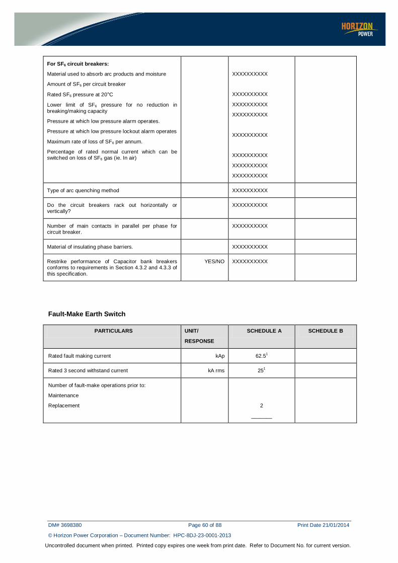
DM# 3698380 Page 60 of 88 Print Date 21/01/2014
© Horizon Power Corporation – Document Number: HPC-8DJ-23-0001-2013
Uncontrolled document when printed. Printed copy expires one week from print date. Refer to Document No. for current version.
For SF6 circuit breakers:
Material used to absorb arc products and moisture
Amount of SF6 per circuit breaker
Rated SF6 pressure at 20 C
Lower limit of SF6 pressure for no reduction in
breaking/making capacity
Pressure at which low pressure alarm operates.
Pressure at which low pressure lockout alarm operates
Maximum rate of loss of SF6 per annum.
Percentage of rated normal current which can be switched on loss of SF6 gas (ie. In air)
XXXXXXXXXX
XXXXXXXXXX
XXXXXXXXXX
XXXXXXXXXX
XXXXXXXXXX
XXXXXXXXXX
XXXXXXXXXX
XXXXXXXXXX
Type of arc quenching method XXXXXXXXXX
Do the circuit breakers rack out horizontally or vertically?
XXXXXXXXXX
Number of main contacts in parallel per phase for circuit breaker.
XXXXXXXXXX
Material of insulating phase barriers. XXXXXXXXXX
Restrike performance of Capacitor bank breakers conforms to requirements in Section 4.3.2 and 4.3.3 of
this specification.
YES/NO XXXXXXXXXX
Fault-Make Earth Switch
PARTICULARS UNIT/
RESPONSE
SCHEDULE A SCHEDULE B
Rated fault making current kAp 62.51
Rated 3 second withstand current kA rms 251
Number of fault-make operations prior to:
Maintenance
Replacement
2
_______

DM# 3698380 Page 61 of 88 Print Date 21/01/2014
© Horizon Power Corporation – Document Number: HPC-8DJ-23-0001-2013
Uncontrolled document when printed. Printed copy expires one week from print date. Refer to Document No. for current version.
Current Transformers
PARTICULARS UNIT/
RESPONSE
SCHEDULE A SCHEDULE B
TRANSFORMER FEEDER/ CAPACITOR
INTERCONNECTOR / BUS TIE
TX FDR/ CAP
BUS
TIE SEC
Advise CT parameters and
classifications:
Core A ratios
Core A class
Main Protection
1600/1 3
0.05PX400R5
1600/1 3
0.05PX400R5
Core B ratios
Core B class
Bus Zone 1600/1 3
0.05PX400R5
1600/1 3
0.05PX400R5
1600/1 3
0.05PX400R5
Core C ratios
Core C class
Metering/
Backup Protection
1600/1 MR 3
0.5M/2.5P300F30
600/1 MR 3
0.5M/2.5P300F30
1200/1 MR 3
0.5M/2.5P300F30
Core D ratios
Core D class
Metering 1600/1 MR 3
0.2M, 15VA
600/1 MR 3
0.2M, 15VA
1200/1 MR 3
0.2M, 15VA
Secondary withstand voltage
Thermal limit secondary current
Number of cores per
phase
Physical configuration of cores
kV
A
2 kV for one minute
2 A
_____________
_____________
2 kV for one minute
2 A
___________
_____________
2 kV for one minute
2 A
____________
_____________
Is core balance transformer required for cables?
YES/NO XXXXXXXXXX XXXXXXXXXX XXXXXXXXXX
Partial discharge level 1.1 x rated line to
neutral rated voltage
pC XXXXXXXXXX XXXXXXXXXX XXXXXXXXXX
Can each core be operated continuously
with open circuited secondary?
YES/NO XXXXXXXXXX XXXXXXXXXX XXXXXXXXXX
Is the current transformer within HV compartment shielded
from flashover due to primary faults?
YES/NO XXXXXXXXXX XXXXXXXXXX XXXXXXXXXX

DM# 3698380 Page 62 of 88 Print Date 21/01/2014
© Horizon Power Corporation – Document Number: HPC-8DJ-23-0001-2013
Uncontrolled document when printed. Printed copy expires one week from print date. Refer to Document No. for current version.
Voltage Transformers
PARTICULARS UNIT/
RESPONSE
SCHEDULE A SCHEDULE B
Advise VT parameters and classifications:
Rated phase to primary voltage
Rated phase to phase secondary voltage
Connections
Category of performance
Accuracy class
Rated burden/output
Rated voltage factor and duration
kV
V
22
110
YN/yn
B
0.2M
50
1.9
Partial discharge level at 1.1 x rated line to neutral voltage (alternatively 1.1 x rated line to line voltage for “V” connected
voltage transformer)
pC XXXXXXXXXX
Lightning impulse withstand voltage of primary neutral
kVp 125
One minute power frequency withstand voltage of primary neutral
kV rms 50
Can the HV neutral be operated unearthed?
YES/NO XXXXXXXXXX
Are the voltage transformers fused on the
HV side?
YES/NO XXXXXXXXXX
Cable box
PARTICULARS UNIT/
RESPONSE
SCHEDULE A SCHEDULE B
Dedicated feeders
Power cable size
Power cable type
Power cable quantity
Normal feeders
Power cable size
Power cable type
Power cable quantity
Transformer circuits
Power cable size Vendor specified
Power cable type Vendor specified
Power cable quantity Vendor specified
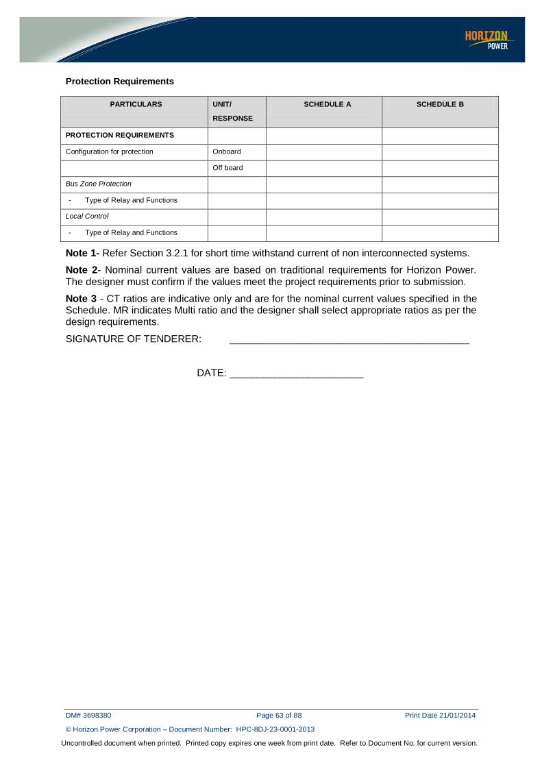
DM# 3698380 Page 63 of 88 Print Date 21/01/2014
© Horizon Power Corporation – Document Number: HPC-8DJ-23-0001-2013
Uncontrolled document when printed. Printed copy expires one week from print date. Refer to Document No. for current version.
Protection Requirements
PARTICULARS UNIT/
RESPONSE
SCHEDULE A SCHEDULE B
PROTECTION REQUIREMENTS
Configuration for protection Onboard
Off board
Bus Zone Protection
- Type of Relay and Functions
Local Control
- Type of Relay and Functions
Note 1- Refer Section 3.2.1 for short time withstand current of non interconnected systems.
Note 2- Nominal current values are based on traditional requirements for Horizon Power.
The designer must confirm if the values meet the project requirements prior to submission.
Note 3 - CT ratios are indicative only and are for the nominal current values specif ied in the Schedule. MR indicates Multi ratio and the designer shall select appropriate ratios as per the design requirements.
SIGNATURE OF TENDERER: ___________________________________________
DATE: ________________________

DM# 3698380 Page 64 of 88 Print Date 21/01/2014
© Horizon Power Corporation – Document Number: HPC-8DJ-23-0001-2013
Uncontrolled document when printed. Printed copy expires one week from print date. Refer to Document No. for current version.
D.4 Technical Schedule for 33 kV switchboard operated at 33 kV
Switchboard Assembly (Common Requirements of all Components)
PARTICULARS UNIT/
RESPONSE
SCHEDULE A SCHEDULE B
Rated voltage/highest equipment voltage kV 33
Rated insulation level
Lightning impulse withstand voltage
- To earth and between phases
- Across the isolating distance
One minute power frequency withstand voltage
- To earth and between poles
- Across the isolating distance
kV
kV
kV
kV
170
195
70
80
Rated frequency Hz 50
Number of phases 3
Rated 3 second short circuit withstand current kA 161
Rated peak withstand current kA 501
Rated 1 sec Internal Arc withstand current kA 161
Nominal Current
Busbar
Transformer circuit
Feeder circuit
Bus tie feeder circuit
A
A
A
A
12502
12502
6302
12502
Earth bar cross section sq. mm 40 mm * 5 mm
Partial discharge level
Each panel assembled with CB at 14 kV rms
Fully assembled switchgear at 14 kV rms
pC
XXXXXXXXXXXXX
XXXXXXXXXXXXX
Degree of protection
Relay panels
Circuit breaker in service position
Circuit breaker in test position
Circuit breaker in withdrawn position
IP
IP
IP
IP
52
52
52
52
Cable box insulation XXXXXXXXXXXXX

DM# 3698380 Page 65 of 88 Print Date 21/01/2014
© Horizon Power Corporation – Document Number: HPC-8DJ-23-0001-2013
Uncontrolled document when printed. Printed copy expires one week from print date. Refer to Document No. for current version.
Control Voltages
Trip and Close Circuit
Spring Charging circuit
Indication circuit
Cubicle heating circuit
V (DC)
V (AC)
V (DC)
V (AC)
110
240
110
240
Have all components been fully type tested with
respect to design/materials and manufacturing process
YES/NO XXXXXXXXXXXXXX
Are the sizes of protection/control wiring as per
Specification?
YES/NO XXXXXXXXXXXXXX
Make and type of current transformer circuit links
to be provided
XXXXXXXXXXXXXX
Are the current transformer circuit links push-pull
disconnecting type?
YES/NO XXXXXXXXXXXXXX
Location of test plugs / links Provide details XXXXXXXXXXXXXX
Are flaps provided in each chamber for arc fault pressure relief?
YES/NO XXXXXXXXXXXXXX
Circuit Breaker
PARTICULARS UNIT/
RESPONSE
SCHEDULE A SCHEDULE B
Rated short circuit breaking current (3 sec)
AC component
DC component 60 ms from initiation of short circuit
kA rms
%
161
Figure 9 of
AS 62271.100 for a time constant of 45 ms
Rated short circuit making current (3 sec) kA 501
X/R ratio 14
First pole to clear factor 1.5
Rated operating sequence O t CO t’ CO
O – 0.3s – CO – 1min – CO
Maximum break time ms 100
Rated small inductive breaking current: A (rms) 20
Rated back-to-back capacitor bank breaking current A _______400_____
Rated cable charging breaking current A 50

DM# 3698380 Page 66 of 88 Print Date 21/01/2014
© Horizon Power Corporation – Document Number: HPC-8DJ-23-0001-2013
Uncontrolled document when printed. Printed copy expires one week from print date. Refer to Document No. for current version.
Rated out of phase breaking current kA (rms) As per Section 4.106 of AS 62271.100
Rated out of phase recovery voltage V As per Section 4.106 of
AS 62271.100
Rated transient recovery voltage V As per Table 24 of AS 62271.100
Rated capacitor bank inrush making current (for back to back switching)
kAp As per Table 5 of AS 62271.100
Minimum Breaker Opening time at:
100% auxiliary supply voltage
70% auxiliary supply voltage
ms
ms
XXXXXXXXXXXX
XXXXXXXXXXXX
Is the circuit breaker fixed trip or trip free? XXXXXXXXXXXX
Duration of fault current let through on a C-O operation ms XXXXXXXXXXXX
Resistance of trip coil at 20 C ohms XXXXXXXXXXXX
Tripping current at rated DC voltage A XXXXXXXXXXXX
Trip coil voltage operating range
Upper limit
Lower limit
%
%
120
70
Minimum current to hold trip coil in after energisation mA XXXXXXXXXXXX
Resistance of closing coil at 20 C ohms XXXXXXXXXXXX
Closing current at rated DC. voltage A XXXXXXXXXXXX
Closing coil voltage operating range
upper limit
lower limit
%
%
120
85
Do the circuit breakers meet the requirements for
single phase short circuit testing to AS 62271.100? If not, what is the maximum short circuit breaking current for this case?
XXXXXXXXXXX
Rating of auxiliary switches
Make and carry continuously
Break inductive current (time constant 40 ms) at 110 V
DC
A
A
10
2
Number of operations permitted without inspection/maintenance
(1 close + 1 open = 1 operation)
At rated normal current
At rated short circuit breaking current
At 50% rated short circuit breaking current
At rated capacitor breaking current
5,000
________
________
________

DM# 3698380 Page 67 of 88 Print Date 21/01/2014
© Horizon Power Corporation – Document Number: HPC-8DJ-23-0001-2013
Uncontrolled document when printed. Printed copy expires one week from print date. Refer to Document No. for current version.
Operating mechanisms
Inspection free interval
Maintenance free interval
months
months
XXXXXXXXXXX
XXXXXXXXXXX
Number of spare auxiliary contacts available to
Purchaser
Normally open
Normally closed
6
6
Guaranteed number of close-open operations prior to
interrupter replacement.
At rated normal current
At rated short circuit current
10,000
________
Have the circuit breakers of each rating been fully type tested as per AS 62271.100
YES/NO XXXXXXXXXX
For vacuum circuit breakers:
Make of vacuum bottle
What is the shelf life of the bottle?
What method is used to check integrity of the vacuum?
What method is used to check contact wear?
X-radiation with 33 kV rms applied across interrupter
Voltage withstand capacity across the contacts on loss of vacuum
Percentage of rated normal current which can be
switched on loss of vacuum
XXXXXXXXXXX
XXXXXXXXXX
XXXXXXXXXX
XXXXXXXXXX
XXXXXXXXXX
XXXXXXXXXX
XXXXXXXXXX
For SF6 circuit breakers:
Material used to absorb arc products and moisture
Amount of SF6 per circuit breaker
Rated SF6 pressure at 20 C
Lower limit of SF6 pressure for no reduction in
breaking/making capacity
Pressure at which low pressure alarm operates.
Pressure at which low pressure lockout alarm operates
Maximum rate of loss of SF6 per annum.
Percentage of rated normal current which can be switched on loss of SF6 gas (i.e. In air)
XXXXXXXXXX
XXXXXXXXXX
XXXXXXXXXX
XXXXXXXXXX
XXXXXXXXXX
XXXXXXXXXX
XXXXXXXXXX
XXXXXXXXXX
Type of arc quenching method XXXXXXXXXX

DM# 3698380 Page 68 of 88 Print Date 21/01/2014
© Horizon Power Corporation – Document Number: HPC-8DJ-23-0001-2013
Uncontrolled document when printed. Printed copy expires one week from print date. Refer to Document No. for current version.
Do the circuit breakers rack out horizontally or vertically?
XXXXXXXXXX
Number of main contacts in parallel per phase for
circuit breaker.
XXXXXXXXXX
Material of insulating phase barriers. XXXXXXXXXX
Restrike performance of Capacitor bank breakers conforms with requirements in Section 4.3.2 and 4.3.3 of this specification.
YES/NO XXXXXXXXXX
Fault-Make Earth Switch
PARTICULARS UNIT/
RESPONSE
SCHEDULE A SCHEDULE B
Rated fault making current kAp 501
Rated 3 second withstand current kA rms 161
Number of fault-make operations prior to:
Maintenance
Replacement
2
________
Current Transformers
PARTICULARS UNIT/
RESPONSE
SCHEDULE A SCHEDULE B
TRANSFORMER FEEDER/ CAPACITOR
BUS SECTION TX FDR
/ CAP
BUS
TIE SECTION
Advise CT parameters and classifications:
Core A ratios
Core A class
Main Protection
1200/1 3
0.05PX400R5
1200/1 3
0.05PX400R5
Core B ratios
Core B class
Bus Zone 1200/1 3
0.05PX400R5
1200/1 3
0.05PX400R5
1200/1 3
0.05PX400R5
Core C ratios
Core C class
Metering/ Backup
Protection
1200/1 MR 3
0.5M/2.5P300F30
600/1 MR 3
0.5M/2.5P300F30
1200/1 MR 3
0.5M/2.5P300F30
Core D ratios
Core D class
Metering 1200/1 MR 3
0.2M, 15VA
600/1 MR 3
0.2M, 15VA
1200/1 MR 3
0.2M, 15VA
Secondary withstand voltage
Thermal limit
secondary current
Number of cores per phase
Physical configuration of cores
kV
A
2 kV for one minute
2 A
_____________
_____________
2 kV for one minute
2 A
___________
_____________
2 kV for one minute
2 A
____________
_____________

DM# 3698380 Page 69 of 88 Print Date 21/01/2014
© Horizon Power Corporation – Document Number: HPC-8DJ-23-0001-2013
Uncontrolled document when printed. Printed copy expires one week from print date. Refer to Document No. for current version.
Is core balance transformer required for cables?
YES/NO XXXXXXXXXX XXXXXXXXXX XXXXXXXXXX
Partial discharge level 1.1 x rated line to neutral rated voltage
pC XXXXXXXXXX XXXXXXXXXX XXXXXXXXXX
Can each core be operated continuously with open circuited
secondary?
YES/NO XXXXXXXXXX XXXXXXXXXX XXXXXXXXXX
Is the current
transformer within HV compartment shielded from flashover due to primary faults?
YES/NO XXXXXXXXXX XXXXXXXXXX XXXXXXXXXX
Voltage Transformers
PARTICULARS UNIT/
RESPONSE
SCHEDULE B SCHEDULE B
Advise VT parameters and classifications:
Rated phase to primary voltage
Rated phase to phase secondary voltage
Connections
Category of performance
Accuracy class
Rated burden/output
Rated voltage factor and duration
kV
V
33
110
YN/yn
B
0.2M
50
1.9
Partial discharge level at 1.1 x rated line to neutral voltage (alternatively 1.1 x rated line to line voltage for “V” connected
voltage transformer)
pC XXXXXXXXXX
Lightning impulse withstand voltage of
primary neutral
kVp 170
One minute power frequency withstand voltage of primary neutral
kV rms 70
Can the HV neutral be operated unearthed?
YES/NO XXXXXXXXXX
Are the voltage transformers fused on the HV side?
YES/NO XXXXXXXXXX

DM# 3698380 Page 70 of 88 Print Date 21/01/2014
© Horizon Power Corporation – Document Number: HPC-8DJ-23-0001-2013
Uncontrolled document when printed. Printed copy expires one week from print date. Refer to Document No. for current version.
Cable box
PARTICULARS UNIT/
RESPONSE
SCHEDULE A SCHEDULE B
Dedicated feeders
Power cable size
Power cable type
Power cable quantity
Normal feeders
Power cable size
Power cable type
Power cable quantity
Transformer circuits
Power cable size Vendor specified
Power cable type Vendor specified
Power cable quantity Vendor specified
Protection Requirements
PARTICULARS UNIT/
RESPONSE
SCHEDULE A SCHEDULE B
PROTECTION REQUIREMENTS
Configuration for protection
Onboard
Off board
Bus Zone Protection
- Type of Relay and Functions
Local Control
- Type of Relay and Functions
Note 1- Refer Section 3.2.1 for short time withstand current of non interconnected systems.
Note 2- Nominal current values are based on traditional requirements for Horizon Power.
The designer must confirm if the values meet the project requirements prior to submission.
Note 3 - CT ratios are indicative only and are for the nominal current values specified in the Schedule. MR indicates Multi ratio and the designer shall select appropriate ratios as per the design requirements.
SIGNATURE OF TENDERER: ___________________________________________
DATE: ________________________

DM# 3698380 Page 71 of 88 Print Date 21/01/2014
© Horizon Power Corporation – Document Number: HPC-8DJ-23-0001-2013
Uncontrolled document when printed. Printed copy expires one week from print date. Refer to Document No. for current version.
APPENDIX E – COMPLIANCE DOCUMENT
The Vendor shall indicate below whether this offer is fully compliant with the nominated clause in this Specification. A YES shall ONLY be indicated if the offer is 100% compliant with the relevant Clause. If NO is indicated and supporting documents are submitted, then mark the ATT box with the attachment number. Details of departure shall be provided in Appendix F.
CLAUSE NUMBER YES NO ATT.
1. SCOPE
2. NORMATIVE REFERENCES 2.1 Standards 2.2 Definitions and Abbreviations 2.2.1 Definitions 2.2.2 Abbreviations
3 REQUIREMENTS 3.1 General 3.2 Power System Particulars
3.2.1 Design Fault Levels 3.2.2 Nominal System Frequency 3.2.3 System Insulation Levels 3.2.4 Operating Conditions 3.2.5 Clearances & Insulation 3.2.6 Dimensions 4 SWITCHBOARD DESIGN AND CONSTRUCTION 4.1 General Requirements 4.1.1 Partition Class 4.1.2 Loss of Service Continuity 4.2 Switchboard Layout 4.2.1 Rated Parameters and Performance 4.2.2 Enclosure
4.2.3 Compartments 4.2.3.1 General requirement 4.2.3.2 Doors 4.2.4 Shutters 4.2.5 Fixing of Equipment on Side Walls 4.2.6 Venting 4.2.6.1 Internal Arc Classification (IAC) 4.2.6.2 Explosion Relief Chamber and Ducting
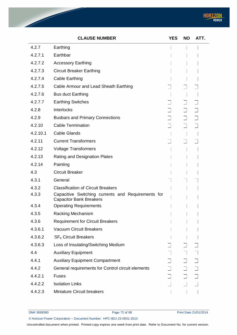
DM# 3698380 Page 72 of 88 Print Date 21/01/2014
© Horizon Power Corporation – Document Number: HPC-8DJ-23-0001-2013
Uncontrolled document when printed. Printed copy expires one week from print date. Refer to Document No. for current version.
CLAUSE NUMBER YES NO ATT.
4.2.7 Earthing 4.2.7.1 Earthbar 4.2.7.2 Accessory Earthing 4.2.7.3 Circuit Breaker Earthing 4.2.7.4 Cable Earthing 4.2.7.5 Cable Armour and Lead Sheath Earthing 4.2.7.6 Bus duct Earthing 4.2.7.7 Earthing Switches 4.2.8 Interlocks 4.2.9 Busbars and Primary Connections 4.2.10 Cable Termination 4.2.10.1 Cable Glands 4.2.11 Current Transformers 4.2.12 Voltage Transformers 4.2.13 Rating and Designation Plates 4.2.14 Painting 4.3 Circuit Breaker 4.3.1 General 4.3.2 Classification of Circuit Breakers 4.3.3 Capacitive Switching currents and Requirements for
Capacitor Bank Breakers
4.3.4 Operating Requirements 4.3.5 Racking Mechanism 4.3.6 Requirement for Circuit Breakers 4.3.6.1 Vacuum Circuit Breakers 4.3.6.2 SF6 Circuit Breakers 4.3.6.3 Loss of Insulating/Switching Medium 4.4 Auxiliary Equipment 4.4.1 Auxiliary Equipment Compartment 4.4.2 General requirements for Control circuit elements 4.4.2.1 Fuses 4.4.2.2 Isolation Links 4.4.2.3 Miniature Circuit breakers
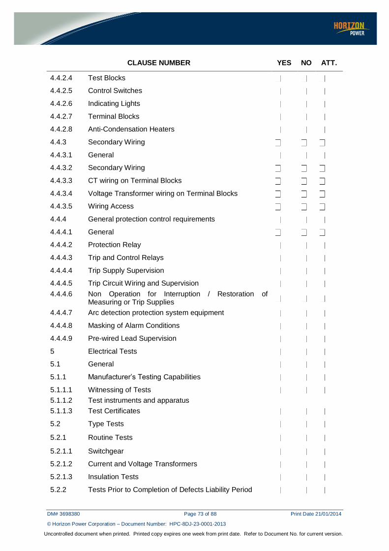
DM# 3698380 Page 73 of 88 Print Date 21/01/2014
© Horizon Power Corporation – Document Number: HPC-8DJ-23-0001-2013
Uncontrolled document when printed. Printed copy expires one week from print date. Refer to Document No. for current version.
CLAUSE NUMBER YES NO ATT.
4.4.2.4 Test Blocks 4.4.2.5 Control Switches 4.4.2.6 Indicating Lights 4.4.2.7 Terminal Blocks 4.4.2.8 Anti-Condensation Heaters 4.4.3 Secondary Wiring 4.4.3.1 General 4.4.3.2 Secondary Wiring 4.4.3.3 CT wiring on Terminal Blocks 4.4.3.4 Voltage Transformer wiring on Terminal Blocks 4.4.3.5 Wiring Access 4.4.4 General protection control requirements 4.4.4.1 General 4.4.4.2 Protection Relay 4.4.4.3 Trip and Control Relays 4.4.4.4 Trip Supply Supervision 4.4.4.5 Trip Circuit Wiring and Supervision 4.4.4.6 Non Operation for Interruption / Restoration of
Measuring or Trip Supplies
4.4.4.7 Arc detection protection system equipment 4.4.4.8 Masking of Alarm Conditions 4.4.4.9 Pre-wired Lead Supervision 5 Electrical Tests 5.1 General 5.1.1 Manufacturer’s Testing Capabilities 5.1.1.1 Witnessing of Tests 5.1.1.2 Test instruments and apparatus
5.1.1.3 Test Certificates 5.2 Type Tests 5.2.1 Routine Tests 5.2.1.1 Switchgear 5.2.1.2 Current and Voltage Transformers 5.2.1.3 Insulation Tests 5.2.2 Tests Prior to Completion of Defects Liability Period

DM# 3698380 Page 74 of 88 Print Date 21/01/2014
© Horizon Power Corporation – Document Number: HPC-8DJ-23-0001-2013
Uncontrolled document when printed. Printed copy expires one week from print date. Refer to Document No. for current version.
CLAUSE NUMBER YES NO ATT.
6 STORAGE
7 RELIABILITY
8 ENVIRONMENTAL CONSIDERATIONS
9 DOCUMENTATION 9.1 Type Test Certificates/Reports 10 PACKAGING REQUIREMENTS
11 SPARE EQUIPMENT

DM# 3698380 Page 75 of 88 Print Date 21/01/2014
© Horizon Power Corporation – Document Number: HPC-8DJ-23-0001-2013
Uncontrolled document when printed. Printed copy expires one week from print date. Refer to Document No. for current version.
APPENDIX F – DEPARTURES FROM TECHNICAL SPECIFICATION
The Vendor shall nominate the Clause and describe the departure:
CLAUSE NO DEPARTURE

DM# 3698380 Page 76 of 88 Print Date 21/01/2014
© Horizon Power Corporation – Document Number: HPC-8DJ-23-0001-2013
Uncontrolled document when printed. Printed copy expires one week from print date. Refer to Document No. for current version.
APPENDIX G – MISCELLANEOUS INFORMATION
SIZE AND VOLTAGE GRADE OF WIRES FOR PANEL WIRING
APPLICATION SIZE
VOLTAGE GRADE
COLOUR AREA (mm²) STRANDING
(mm)
VT Secondary Circuits
CT Secondary Circuits (1 A)
CT Secondary Circuits (5 A)
240 V AC Power Circuits *
415 V AC Power Circuits *
1.5
1.5
1.5
1.5
1.5
7/0.5
7/0.5
7/0.5
7/0.5
7/0.5
0.6/1 kV
0.6/1 kV
0.6/1 kV
0.6/1 kV
0.6/1 kV
} Phase:
} R, W, B
}
} Neutral
} Bk
}
110, 230, 250 volt DC
control and Indication
circuits.
50 V DC Control indication
and Telemetry Circuits
32 V DC Control circuits
1.5
0.5
4
7/0.5
16/0.2 or 7/0.3
7/0.85
0.6/1 kV
50V
0.6/1 kV
Grey
Brown
-
Power Circuits 6
6
35
7/1.04
7/1.7
19/1.53
0.6/1 kV
0.6/1 kV
0.6/1 kV
} Phase
} R, W, B
} Neutral:
} Bk
Wires sizes are minimum permissible. Wire must be sized to suit load current and/or voltage drop requirements.

DM# 3698380 Page 77 of 88 Print Date 21/01/2014
© Horizon Power Corporation – Document Number: HPC-8DJ-23-0001-2013
Uncontrolled document when printed. Printed copy expires one week from print date. Refer to Document No. for current version.
TERMINALS
The standard range of terminals is as listed below. For special applications the manufacturers catalogues should be consulted for the appropriate terminal type. Phoenix terminals equivalent to Klippon are acceptable.
APPLICATION APPROVED TERMINALS
CT and VT secondary circuits DC control
WDU 4 (4 mm2 32 A)
WDU 4 / ZR (4 mm2 32 A)
WTR 4 StB (4 mm2 32 A Disconnect)
WTL 6/1 StB (6 mm2 41 A Earth link)
AC and DC power WDU 4 (4 mm2 32 A)
WDU 4 / ZR (4 mm2 32 A
WTR 4 StB (4 mm2 32 A Disconnect)
WDU 6 (6 mm2 41 A)
WDU 16 (16 mm2 76 A)
WDU 35 (35 mm2 125 A)
Circuits up to 41 A subject to vibration
(see Section 7.4)
WDU 4 SL (4 mm2 32 A)
WDU 6 SL (6 mm2 41 A)
Light current (control, indication, alarm, metering, telephone)
KRONE 6468 5 (on STRs only)*
WDU 4 (4 mm2 32 A)
WTR 4 StB (4 mm2 32 A Disconnect)
*New sites will use Krone blocks. Other sites will use terminals to match existing fittings.

DM# 3698380 Page 78 of 88 Print Date 21/01/2014
© Horizon Power Corporation – Document Number: HPC-8DJ-23-0001-2013
Uncontrolled document when printed. Printed copy expires one week from print date. Refer to Document No. for current version.
CORRELATION BETWEEN ALPHANUMERIC NOTATION, SYMBOLS AND COLOURS
DESIGNATION OF CONDUCTORS
ALPHANUMERIC NOTATION COLOUR
Alternating current system
Phase 1
Supply Phase 2
Phase 3
L1
L2
L3
Red
White
Blue
Neutral N Black
Phase 1
Apparatus Phase 2
Phase 3
U
V
W
Red
White
Blue
Battery Supply
Positive
Negative
Mid-wire
L +
L –
M
Red
Black
Blue
Earth E Green/Yellow
COLOURS FOR SMALL WIRING
COLOUR OF WIRE
CIRCUIT PARTICULARS
Red
White
Blue
Phase connections, whether earthed or unearthed, either directly connected to the primary circuit, or connected to secondary circuits of current and voltage transformers.
Black AC neutral connections, earthed or unearthed, either directly connected to the primary circuit or connected to the secondary circuit of current and voltage transformers. AC connections other than those above and connections in AC/DC circuits.
Green/Yellow Connections to earth.
Grey Connections in 110 V and 230 V DC protection circuits for No. 1 battery.
Grey Connections in 110 V and 230 V DC protection circuits for No. 2 battery.

DM# 3698380 Page 79 of 88 Print Date 21/01/2014
© Horizon Power Corporation – Document Number: HPC-8DJ-23-0001-2013
Uncontrolled document when printed. Printed copy expires one week from print date. Refer to Document No. for current version.
Brown All 50 V DC control circuits, indication, alarm, supervisory, telephone.
Pink All 110 V AC control circuits, Pilots and connections between protection equipment components including 110 V
Brown Telemetering circuits including outputs from transformer/rectifier units.
CIRCUIT FUNCTION LETTERS AND WIRE NUMBERS
FUNCTION
LETTER
CIRCUIT FUNCTION WIRE NUMBERS
A Current transformers for primary protection excluding overcurrent.
10 to 29 – Red Phase
30 to 49 – White Phase
50 to 69 – Blue Phase
70 to 89 – Residual circuits and Neutral current transformers
90 – Earth wire directly connected to the earth bar
91 – 99 Test windings normally inoperative
B Current transformers for busbar protection.
C Current transformers for overcurrent, earth fault protection and instruments.
D Current transformers for metering and voltage control.
E Reference voltage for instruments, metering and protection.
F Reference voltage for voltage control.
G Reference voltage for synchronising.
DE DC side of metering transducers for voltage.
Any number > 1.
DD DC side of metering transducers for current.
DF DC side of frequency transducers.
DP DC side of power factor transducers.
DR DC side of metering transducers, for reactive power.
DW DC side of metering transducers for real power.
DT DC side of metering transducers for temperature.

DM# 3698380 Page 80 of 88 Print Date 21/01/2014
© Horizon Power Corporation – Document Number: HPC-8DJ-23-0001-2013
Uncontrolled document when printed. Printed copy expires one week from print date. Refer to Document No. for current version.
H AC supplies. As for A-G but within the following range:
110 V Unearthed or Centre Tapped Earth:
(200-339)
240 V and 415 V
(400-799)
Other:
(800-899)
J DC supplies. 50 V Circuits
No. 1 Battery (1-199)
No. 2 Battery (400-599)
110 V Circuits
No. 1 Battery (200-399)
No. 2 Battery (600-799)
230 V Circuits
No. 1 Battery (200-399)
No. 2 Battery (600-799)
Other
(800-999)
K Closing and tripping control circuits excluding those for light current remote selection and control covered under W
As for J
L Alarm and indication circuits initiated by auxiliary switches and relay contacts, excluding those for light current remote general indication and alarm equipment covered under X.
As for J
M Auxiliary and control motor devices e.g., governor motor rheostat motor, generator automatic voltage regulator control, spring charging motors, transformer cooler motor control, motors for isolator operation.
As for J
N Tap-change control, including automatic voltage control, tap position and progress indications.
As for J

DM# 3698380 Page 81 of 88 Print Date 21/01/2014
© Horizon Power Corporation – Document Number: HPC-8DJ-23-0001-2013
Uncontrolled document when printed. Printed copy expires one week from print date. Refer to Document No. for current version.
O An indication that the ferruling is not in accordance with the general scheme and that if it is not altered double ferruling will be required for co-ordination with the remaining equipment in the station.
P DC tripping circuits used solely for busbar protection.
R Interlock circuits not covered above.
S DC instruments (with the exception of output from watts, amps, volts, power factor frequency, VAr transducers) and relays, exciter and field circuits for generators e.g. fault recorders.
T Pilot conductors and connections between protection equipment components (incl. directly associated connections) between panels independent of the distance between them e.g. Pilot wire protection (for DC inter-tripping use K.)
U Spare cores and connections to spare contacts
V Automatic switching circuits not integral with circuit breaker control schemes ie separately supplied, or isolatable from the circuit breaker control scheme.
W Control connections in light current circuits.
X Alarm and indication connections associated with remote light current general indication and selective control schemes.
Y Telephones
NOTE: If for functions A-G and H more numbers are required, add multiples of one
hundred e.g. 10-29 may be extended to 110-129, 210-229, 410-429 but excluding numbers 310-329 which are reserved for duplicate primary protection.
DM# 3698380 Page 82 of 88 Print Date 21/01/2014
© Horizon Power Corporation – Document Number: HPC-8DJ-23-0001-2013
Uncontrolled document when printed. Printed copy expires one week from print date. Refer to Document No. for current version.
SPECIFIC REQUIREMENTS FOR PROTECTION DRAWINGS
Auxiliary compartment equipment arrangement
A scaled drawing shall show when viewed from the front the layout of all Equipment contained on or within each compartment.
Each item of Equipment, including the compartment itself, terminal strip and labels shall be identified with a number referenced to an Equipment list.
Equipment label inscription details may be shown on a separate schedule in a similar format to drawing SS1/14/1/63/1
Terminal arrangement in compartment
The arrangement of each terminal strip shall be shown on a drawing detailing:
1. The sequence and grouping of terminals in which they are installed in the equipment.
2. Detail type of terminal. 3. Detail wire number and terminal number if not same.
Terminal diagrams shall be shown in a similar format to drawing SS1/14/1/64/1.
Schematic circuit diagrams
Schematic diagrams shall be supplied for all Equipment unless approval for non-supply is granted.
Schematic diagrams for protection circuits shall show the Current Transformer and Voltage Transformer AC circuitry and DC circuitry from the 110 V battery all on separate drawings.
Cross referencing between drawings shall be to the satisfaction of the HP and shall generally be only between three types of drawings listed above.
Symbols for coils, contacts, devices etc. shall be in accordance with AS 1102.
The Schematic diagrams shall be arranged to read from left to right or top to bottom with power flow or positive to negative in the case of DC circuits, or order of operating sequence.
The schematic diagrams shall be similar to the drawings provided and shall detail the following:
1. Each item of equipment component identified (may be abbreviated to the satisfaction of HP).
2. All wire numbers and terminal numbers. 3. Ratings and ratios of windings, fuses, resistors, motors, heaters, etc. 4. Relationship of coils and associated contacts and multi-contacts switches. 5. This shall preferably be by dotted line.
Block representation of equipment shall not be used without approval of the HP generally will only be acceptable for electronic devices. In any case input and output/function terminals must be identified, as well as the current paths relevant to the drawing.

DM# 3698380 Page 83 of 88 Print Date 21/01/2014
© Horizon Power Corporation – Document Number: HPC-8DJ-23-0001-2013
Uncontrolled document when printed. Printed copy expires one week from print date. Refer to Document No. for current version.
Compartment drawings
Drawings for compartment equipment other than the Approved relays and devices listed in this Specification shall include drawings of:
1. Outline showing principle dimensions and all parts affecting electrical clearances, mounting details and terminal details.
2. Details of module or card locations in the case of solid state equipment. 3. Interconnection wiring between modules (where applicable). 4. Schematics of all circuits and modules to component level, with
component specifications and terminal details. 5. Layout of components on cards or modules (where applicable).
SPECIFIC REQUIREMENTS FOR LABEL INSCRIPTIONS
SCHED14.DGN – a drawing combining material list and label inscription shall be used.
Label information, e.g., size, colour, quantity and inscription, may be detailed on the following black schedules, which are in CADAD area [240,100]
TP-REF:
SCHED10.DGN - Fuse Label Schedule
SCHED11.DGN - Link Label Schedule
SCHED12.DGN - Label Schedule (2 line inscriptions)
Inscriptions
General
In the label inscriptions schedule, the inscription on a particular line, will be separated from those on other lines by commas, which shall NOT be included on the label when engraved.
Where abbreviations are used, full stops shall NOT be included in the inscription. Abbreviations shall be identical to those used on the schematic diagrams. Refer to drawing number SS119/15/1/3 Relay Abbreviations.
Relays
The word relay, or any abbreviation thereof, should not be included in the inscription of a label defining the type relay with which it is associated. The main function of the relay should be shown on the first line and ancillary information on subsequent lines. The inscription shall include, in brackets, the relay abbreviation that appears on the associated link label eg. for a local back-up trip relay the label inscription should be “TRIP (LBU1TR), LOAL BACK-UP NO1”
The rear mounted relay identification label shall be size 8 on drawing number
SS1-14-0-69-1 and be inscribed with line 1 inscription on the front label eg. “TRIP (LBU1TR)”.

DM# 3698380 Page 84 of 88 Print Date 21/01/2014
© Horizon Power Corporation – Document Number: HPC-8DJ-23-0001-2013
Uncontrolled document when printed. Printed copy expires one week from print date. Refer to Document No. for current version.
Fuses
Main supply fuse labels should show the material list Ref. No., circuit function, the voltage, the polarity or phase, the rating and the fuse number e.g.
“[4] PROT1, 110 V, +,20 A, FS21” or
“[6] DIST PROT, 110 V, R, 6 A, FS8” or
“[30] ISOL 853.3, 440 V, Y, 20 A, FS20”
For all fuses, the label inscription shall be shown for the size 3 label on drawing number SS1-14-0-69-1. A second label for rear identification of back connected fuses, shall be inscribed with just the fuse number, as shown for the size 5 label on the same drawing.
For front connected fuses, only one label is required.
Sub-circuit fuse labels should show the sub-circuit function, the voltage, the polarity or phase, the rating and the fuse number e.g.
“CB CTRL, 110 V, +, 6 A, FS23” or
“NO VOLT, INT’LOCK, 110 V, R, 6 A, FS81”
The words phase, positive, negative or any abbreviations or symbols for these words shall not be used, except that + or – shall be used to indicate polarity in DC schemes.
Isolation Links
The label inscription should provide sufficient information for the link’s purpose to be clearly understood. Because of space limitations, inscriptions must be concise without losing their meaning to staff familiar with the equipment. To attain this, the following information only should be displayed.
Circuit Isolation Links
On the first line of the inscription shown, in abbreviated form, the name of the relay which will be rendered inoperable when the link is opened. If there is more than one such relay, these shall be shown on subsequent lines. The polarity or phase should then be shown, followed by the link number e.g. “BLBU1, +, LK3”.
Relay, MCB etc, Contact Isolating Links
Where a relay is caused to operate by a contact in another device, the first line of the inscription will show in abbreviated form the name of the relay which is caused to operate by the contact, the next line will shown in abbreviated form the name of the relay, MCB, etc., in which the contact will be found. This description shall be enclosed in brackets. The last line will be the link number. Where links are provided on each side of a relay contact, the label inscription shall be same for both, except for the link number. In some cases the opening of a link will prevent a circuit breaker closing or tripping. In these cases the circuit breaker number will be used in the space reserved for the relay name in the label inscription.
Separation Links
These are links used to separate schemes from each other but the opening of which does not render either scheme inoperable, (e.g. HV and LV protection on a transformer), and are usually referred to as inter-tripping links. Such links shall be provided with labels inscribed as follows. The first line will show the name of the plant protected by the schemes, the next line will show the protection involved, the following line will be

DM# 3698380 Page 85 of 88 Print Date 21/01/2014
© Horizon Power Corporation – Document Number: HPC-8DJ-23-0001-2013
Uncontrolled document when printed. Printed copy expires one week from print date. Refer to Document No. for current version.
engraved "INTERTRIP” and the last line will show the link number e.g. in a transformer protection scheme with inter-tripping facilities between the HV and LV protection, the inscription on the label for the inter-tripping links shall be “T1 HV-LV, PROT 2, INTERTRIP, LK26”.
Links which cannot be included in any of the above categories shall be provided with labels having an inscription based as nearly as possible on the principles stated above.
Characters Per Line
When used, opening and closing brackets shall not be counted when determining the number of letters in a line. Where the number of letters in a description exceeds the allowable number for one line, the continuation of the description on the next line shall be indicated by the use of the oblique stroke “/” followed immediately by a comma indicating the end of the inscription on that line.
Test Blocks
The label inscription for test blocks should show the block number, the description of the circuit in which the blocks are located and the function of the blocks e.g., for current test links in a distance protection scheme, the inscription should be “CLK3 DIST PROT”. The label for the associated earth link should read “ELK3 DIST PROT”. In busbar protection schemes, the primary circuit identification 9 e.g. WT81) will also be included in the label inscription. In cases where VT secondaries are also connected to test blocks, similar information shall be displayed on a separate label as that displayed for current transformer secondaries eg. “CLK3 DIST PROT, VT918”.
Other Items
Other items, such as VT test terminals, interposing VT’s and CT’s and similar items should be provided with a label inscribed to follow the general principles outlined above. Meters, telemeters and transducers should not have the word “meter” etc. included in the description eg. for a megawatt telemeter, the inscription would be “MEGAWATTS”, for a kilowatt hour meter “kWh EXPORT.”. Transducers should be provided with labels inscribed “LINE VOLTS” or “LINE AMPS”.
The labels for VT test terminals should indicate the scheme in which the terminal is located and the voltage source e.g. “DIST PORT, VT807b”. If the terminals are not colour coded, separate labels to indicate phasing should be added.
Modular Protection
Where possible, label inscriptions for modular protection equipment shall conform to the requirements detailed above. However, due to the compactness of modular equipment, it may be necessary to use smaller labels with consequent reductions of the inscriptions. In these cases, the standard abbreviations will have to be to Horizon Power approval.

DM# 3698380 Page 86 of 88 Print Date 21/01/2014
© Horizon Power Corporation – Document Number: HPC-8DJ-23-0001-2013
Uncontrolled document when printed. Printed copy expires one week from print date. Refer to Document No. for current version.
WIRING IDENTIFICATION SCHEME
General
The small wiring shall have colours in accordance with the above table. Each wire shall have a prefix letter to denote its function, e.g. control of circuit breaker, current transformer for primary protection, voltage for instruments, metering and protection. The function letter shall be followed by a number identifying the individual wire. Every branch of every connection shall bear the same identification mark. Where it is necessary to identify branches which are common (e.g. current transformer leads), different identification marks for the branches shall be employed only if they are commoned through links, or are connected to separate terminals which are then commoned by removable connections.
The circuit function letters and wire numbers are listed above.
Ferrules
Identification ferrules shall preferably be white insulating material, having a glossy finish to prevent adhesion of dirt. Alternative methods of ferruling can be offered and any such proposal will require the approval of HP. Ferrules and markings shall not be affected by damp or oil and characters shall be clearly and permanently marked in black or with a contrasting colour.
Prefix Letters
These circuit function letters shall be used in accordance with the following:
(i) Circuit Common To More Than One Function
Where part of a circuit is common to more than one function, letters in the table shall be used for the common part. Where the circuits split at a separate contact, (e.g. fuse, link, switch or relay contact) the function letter should change if necessary from the splitting point onwards.
(ii) Circuits Having Functions Not Included In the Table
Circuits having functions not included in the function letter table shall not have prefix letters. For example, circuit or device which provide a continuous indication, such as remote winding temperature indicators or resistance thermometers, should not have a prefix letter unless the circuit of the particular indication already has a function letter. Where, however, an indication or alarm is initiated by the opening or closing of an auxiliary contact prefix ‘L’ or ‘X’ should be used as appropriate.
(iii) Circuits Having Functions Not Assigned by the Purchaser
Where the manufacturer has been unable to ascertain from the Purchaser the function letters and numbering to be assigned to equipment wiring by the time that wiring is required, the manufacturer should himself provide wire numbers preceded by the letter ‘O’. Where the appropriate function letter can only be determined, it shall be preceded by an ‘O’ and followed by the manufacturer’s own number. The same procedure may be applied to equipment or parts of equipment not assigned to specific contracts at the time of manufacture, subject to the purchaser’s approval and to the use of ferruling in accordance with approved standard diagrams as far as they are applicable.

DM# 3698380 Page 87 of 88 Print Date 21/01/2014
© Horizon Power Corporation – Document Number: HPC-8DJ-23-0001-2013
Uncontrolled document when printed. Printed copy expires one week from print date. Refer to Document No. for current version.
(iv) Circuits Employing Relays
Where relays are employed, the coil and the contact circuits do not necessarily bear the same function letter, this could be determined by the function of the individual circuit e.g. the coil circuit of a series flag relay may be ‘K’ by the contact circuits may bear letters such as ‘X’, ‘L’ or ‘N’ as appropriate.
(v) Current Transformers for Protection
Prefix ‘C’ should be used for all types of over current protection (whether used as primary or back-up protection), standby earth fault, generator negative phase sequence, transformer winding temperature protection and instruments fed from separate current transformers. Where duplicate primary protection is applied prefix ‘A’ shall be used for both, with the No. 2 protection being distinguished by adding 300 to the number.
(vi) Current Transformer Connections for Line Drop Compensation or Compounding
Prefix ‘D’ shall be used for these circuits including the primary current side of the isolating transformer, where applicable. The connections to the voltage circuit from this transformer shall be prefix ‘F’.
(vii) Interposing and Auxiliary Transformers
The function letters shall follow through any interposing and auxiliary current and voltage transformers, including such transformers when used for light current circuits, provided that these are not used as isolating transformers to couple circuits which have differing functions.
(viii) Voltage Transformer Connections for Automatic Voltage Control
Prefix ‘F’ shall be used for these circuits.
(ix) Light Current Control Connections
Light current equipment may require numbering schemes differing from the above for complete identification. In such cases, where connections from such equipment are associated with power equipment wire in accordance with this instruction, the numbering of such connections should include the appropriate prefix letter (J, W, X or Y) to distinguish them. The letter ‘W’ is generally used for the light current side of interposing relays for control purposes.
Wire Numbers
The wire numbers may consist of one or more digits as required and as detailed in the following tables.
The 110 V DC battery wiring for the protection needs to be in accordance with the following:
Protection (+) J601
Protection (-) J602
DC supplies from a positive source shall bear odd numbers and DC supplies from a negative source shall bear even numbers. Where coils or resistors are connected in series, the change from odd to even shall be made at the coil or resistor lead nearest to the negative supply.

DM# 3698380 Page 88 of 88 Print Date 21/01/2014
© Horizon Power Corporation – Document Number: HPC-8DJ-23-0001-2013
Uncontrolled document when printed. Printed copy expires one week from print date. Refer to Document No. for current version.
Suffix Letters
Where similarly numbered leads from separate primary equipment are taken to a common panel (e.g. bus zone protection) suffixes A, B, C, etc. shall be used to distinguish them. When more than two sets of leads require are to be distinguished, specific wire numbering schemes appropriate to the case shall be issued by means of an overall diagram showing the scheme to be adopted.