Embed Size (px)
Citation preview
i - i TNA 151: July 1996
Specification TNA 151
Telecom Telephone
Network
Transmission Plan
Access Standards
Spark New Zealand Limited
Wellington
New Zealand
July 1996
Copyright Spark New Zealand Limited 1996
i - ii TNA 151: July 1996
Section/Page
CONTENTS i - i
FIGURES i - iii
RELATED DOCUMENTS i - iv
DATES OF ISSUE i - v
TELECOM DISCLAIMER i - vi
FOREWORD i - vii
1 GENERAL 1.1 International obligations 1 - 1 1.2 Transmission plans 1 - 1 1.3 Telecom network interface specifications 1 - 1 1.4 Telepermit requirements 1 - 2
2 SCOPE 2.1 Transmission Plan 2 - 1 2.2 Objective 2 - 1 2.3 Digital network 2 - 1 2.4 Transmission aspects 2 - 2 2.4.1 Issues 2 - 2 2.4.2 Overall loss 2 - 2 2.4.3 Digital integrity 2 - 2 2.4.4 Echo 2 - 3 2.4.5 Transmission impairment 2 - 3 2.4.6 Noise 2 - 3 3 DEFINITIONS 3
4 NETWORK CONFIGURATIONS 4.1 International telephone connection 4 - 1 4.2 Telecom network and the national system 4 - 1 4.3 Network relationships 4 - 1 4.4 Rules for connection of two end users 4 - 2 4.5 Integrated services digital network 4 - 2 5 REFERENCE POINTS 5.1 General 5 - 1
6 OVERALL NETWORK TRANSMISSION PERFORMANCE 6.1 Transmission Plan 6 - 1 6.2 Loudness rating (LR) 6 - 1 6.3 Overall loudness rating (OLR) 6 - 3 6.4 Sidetone 6 - 3 6.5 Attenuation distortion 6 - 4 6.6 Group delay distortion 6 - 4 6.7 Timing and synchronisation 6 - 4 7 TRANSMISSION LOSS 7.1 Loss plan 7 - 1 7.2 Digital network 7 - 1
8 NOISE AND CROSSTALK 8.1 Digital processes 8 - 1 8.2 Analogue noise components 8 - 1 8.3 Crosstalk 8 - 1
i - iii TNA 151: July 1996
9 ECHO AND STABILITY 9.1 Echo 9 - 1 9.2 Impedance 9 - 1 9.3 Delay 9 - 2 9.4 Echo loss 9 - 2 9.5 Stability loss 9 - 3 9.6 Telephone transmit and receive levels 9 - 4 10 DIGITAL TRANSMISSION IMPAIRMENT 10.1 Quantising distortion units (QDU's) 10 - 1 11 OTHER NETWORKS 11.1 General 11 - 1 11.2 PABX networks 11 - 1 11.3 Other Telecom Networks 11 - 2 12 NETWORK ASSISTANCE OPERATOR'S CIRCUITS 12.1 Loudness rating 12 - 1 12.2 Connection 12 - 1
APPENDICES
Appendix 1 Excerpt from “FINAL ACTS OF THE WORLD ADMINISTRATIVE TELEGRAPH AND TELEPHONE CONFERENCE (WATTC-88), MELBOURNE, 1988

i - iv TNA 151: July 1996
FIGURES
FIG. 1 MAKE-UP OF TYPICAL INTERNATIONAL TELEPHONE CONNECTION FIG. 2 TYPICAL INTERCONNECTIONS BETWEEN NETWORKS FIG. 3 EXAMPLE OF REFERENCE LEVELS ON AN INTERNATIONAL DIGITAL CONNECTION FIG. 4 LOUDNESS RATING AND ECHO LOSS FIG. 5 TELECOM STANDARD IMPEDANCE NETWORKS FIG. 6 EFFECT OF OPERATOR'S CIRCUIT ON RETURN LOSS
i - v TNA 151: July 1996
RELATED DOCUMENTS
ITU-T Recommendations and the current CCITT Blue Book Recommendations:- G. 100 - 191 General Characteristics of International Telephone Connections and Circuits G. 701 - 797 General Aspects of Digital Transmission Systems G. 801 - 958 Digital Networks, Digital Sections and Digital Line Systems O. 41 Phosphometer for Use On Telephone Type Circuits P. 31 Transmission Characteristics for Digital Telephones P. 76 - 79 Determination of Loudness Rating Q. 44 - 45 General Characteristics for International Telephone Connections and Circuits - Signalling & Switching Q. 511 - 522 Exchange Interfaces, Functions and Connections Q. 551 - 554 Transmission Characteristics of Digital Exchanges
• References in this document are to the published ITU-T Recommendations or the CCITT Blue Book Recommendations where they have not been superseded by the respective ITU-T equivalent. They are both referred to as "Recommendations" in the text.
Telecom Specifications TNA 102 Telecom Public Switched Telephone Network (PSTN) Analogue Line Interface PTC 109 PABX Transmission Requirements PTC 110 PABX Network Requirements PTC 200 Requirements for Connection of Customer Equipment to Analogue Lines PTC 217 Requirements for Bandwidth Management Devices PTC 301 Telephone Network Interconnection (using MFC signalling) PTC 331 Telephone Network Interconnection (using ITU No. 7 signalling) PTC 332 Local Network Interconnection
i - vi TNA 151: July 1996
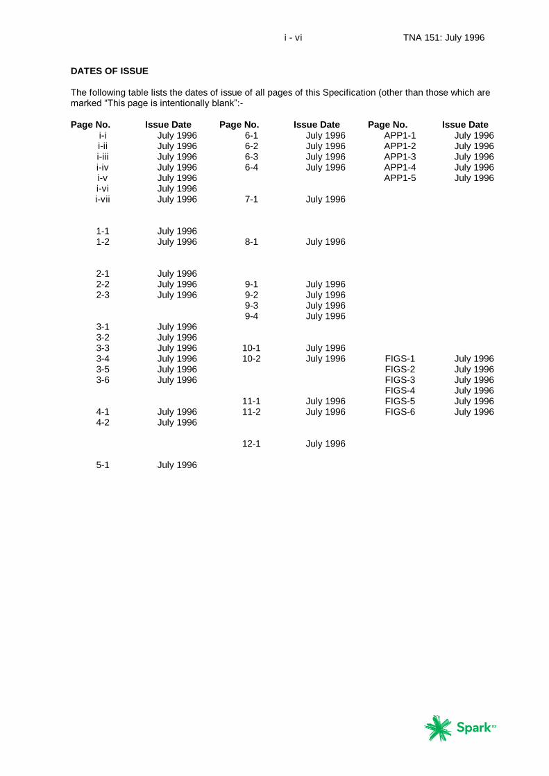
DATES OF ISSUE The following table lists the dates of issue of all pages of this Specification (other than those which are marked “This page is intentionally blank”:- Page No. Issue Date Page No. Issue Date Page No. Issue Date
i-i July 1996 6-1 July 1996 APP1-1 July 1996 i-ii July 1996 6-2 July 1996 APP1-2 July 1996 i-iii July 1996 6-3 July 1996 APP1-3 July 1996 i-iv July 1996 6-4 July 1996 APP1-4 July 1996 i-v July 1996 APP1-5 July 1996 i-vi July 1996 i-vii July 1996 7-1 July 1996
1-1 July 1996 1-2 July 1996 8-1 July 1996
2-1 July 1996 2-2 July 1996 9-1 July 1996 2-3 July 1996 9-2 July 1996
9-3 July 1996 9-4 July 1996
3-1 July 1996 3-2 July 1996 3-3 July 1996 10-1 July 1996 3-4 July 1996 10-2 July 1996 FIGS-1 July 1996 3-5 July 1996 FIGS-2 July 1996 3-6 July 1996 FIGS-3 July 1996
FIGS-4 July 1996 11-1 July 1996 FIGS-5 July 1996
4-1 July 1996 11-2 July 1996 FIGS-6 July 1996 4-2 July 1996
12-1 July 1996
5-1 July 1996

i - vii TNA 151: July 1996
TELECOM DISCLAIMER
Telecom makes no representation or warranty, express or implied, with respect to the
sufficiency, accuracy, or utility of any information or opinion contained in this
Specification. Telecom expressly advises that any use of or reliance on such
information is at the risk of the person concerned.
Telecom shall not be liable for any loss (including consequential loss), damage or
injury incurred by any person or organisation arising out of the sufficiency, accuracy, or
utility of any such information or opinion.
i - viii TNA 151: July 1996
FOREWORD
The primary purpose of this document is to advise telecommunications equipment
suppliers and network operators of the transmission plan being followed by Telecom
in the development of its Public Switched Telephone Network (PSTN). The plan forms
the basis for the more detailed transmission requirements contained in Telecom's
Permit To Connect (PTC) and Telecom Network Advisory (TNA) series of
specifications, which cover the connection of customer premises equipment and
private networks to the Telecom PSTN network, and interconnection with other
network operators. It also reflects into interconnection agreements and other
arrangements.
Transmission plans are used by telecommunications administrations and network
operators to ensure that any two customers, regardless of their location either
nationally or internationally, can satisfactorily communicate via the public switched
network. International consistency between plans is achieved through alignment,
where practicable, with the recommendations of the International Telecommunications
Union, now known as ITU-T recommendations and previously CCITT
recommendations. Country specific and/or network operator specific variations will be
found within plans.
PSTN networks, private networks, customer equipment, and the technologies used
are continually evolving and expanding. Transmission plans consequently need to be
adjusted at intervals. A number of changes have been made to Telecom's Telephone
Transmission Plan since TNA 151 was first published in 1990, and these have now
been incorporated into this document together with the results of a recent review.
Consequently the transmission plan reflects current objectives. However, the existing
Telecom PSTN, private networks, and customer equipment may not necessarily meet
these latest requirements in all respects. Upgrading will generally take place when
equipment addition and/or replacement occurs in line with this 1996 plan.
Readers should direct any queries about this document and its application to Telecom
Access Standards.
References in this document are to the published ITU-T Recommendations or the
CCITT Blue Book Recommendations where they have not been superseded by the
respective ITU-T equivalent. They are both referred to as "Recommendations" in
the text.

i - ix TNA 151: July 1996
THIS PAGE IS INTENTIONALLY BLANK
1 - 1 TNA 151: July 1996
1
GENERAL
1.1
International obligations
(1) The New Zealand Government is a member of the International
Telecommunications Union (ITU) and, along with all other members, agreed at the
1988 World Administrative Telegraph and Teleconference (WATTC-88) in Melbourne
to ensure “that administrations cooperate” and in the international network “a
satisfactory quality of service should be maintained to the greatest extent practicable,
corresponding to relevant ITU-T Recommendations" - see Appendix 1. Accordingly
the Telecom Transmission Plan is in general consistent with Recommendations of the
ITU-T.
(2) This Plan is designed to ensure that any customer connected to the Telecom
PSTN can satisfactorily communicate with any other customer within their own or any
other interconnecting network, including that of an overseas country. The Plan also
covers connections via an individual PABX, or a PABX network, connected to the
Telecom PSTN. Telecom will advise the interconnection requirements for private
networks and negotiate with other network operators to achieve satisfactory
communications.
1.2
Transmission plans
(1) For satisfactory operation it is essential that the transmission performance of any
switched telephone network be properly planned so that an acceptable quality of
signal (speech or data) is achieved for all possible types of call connection.
(2) Other network operators are encouraged to develop their transmission plans in
accordance with ITU-T Recommendations to enable the full range of digital services to
be switched nationally and internationally through a mix of networks as selected by
the customer.
(3) Telecom will continue to update the Plan as technology and customer service
requirements develop.
1.3
Telecom network interface specifications
(1) As will be understood from the issues outlined in this document, the Transmission
Plan is one of the primary bases on which the Telecom PSTN is designed. The plan
also provides a reference for the interconnection of the Telecom PSTN with other
public and private networks within New Zealand.
(2) As there needs to be close correlation between the network and its terminal
equipment if this plan is to be met, Telecom defines its interfaces for the information of
terminal equipment designers in the form of TNA Specifications, of which this is just
one. Telecom’s network interface specifications, especially TNA 102: 1996, are based
on and aligned with this 1996 PSTN Transmission Plan.

1 - 2 TNA 151: July 1996
1.4
Telepermit requirements
Telecom’s Telepermit requirements for customer premises equipment are published in
a series of PTC Specifications. For the analogue network, the primary document is
PTC 200: 1996. The transmission requirements of PTC 200 are also based on and
aligned with this 1996 PSTN Transmission Plan. This should ensure that new
privately-supplied terminal equipment (Customer Premises Equipment or “CPE”) will
progressively be brought into line with this plan.
2 - 1 TNA 151: July 1996
2
SCOPE
2.1
Transmission Plan
(1) This document details the 1996 Transmission Plan for the Telecom Public
Switched Telephone Network (PSTN). Compliance with the Plan should ensure
satisfactory transmission performance for telephony purposes between any two
telephone customers in the Telecom Network, or between any Telecom customer and
customers in other public and private networks, including the International PSTN.
(2) The Plan represents Telecom’s current objectives, and the existing Telecom
PSTN, private networks, and customer equipment may not meet these objectives in all
respects. This is largely a result of refinements which have been necessary as the
technologies used have evolved and been deployed. The process of meeting
changed objectives is one of evolution as the installed base is progressively extended,
rearranged or replaced. Changes to the Plan are made in such a way as to ensure
that transmission quality is maintained.
(3) This Plan places an emphasis on voice telephony transmission requirements.
Digital data in the form of ISDN is covered. Voice band data performance is largely
constrained by provision made for voice telephony.
(4) For the purposes of this plan, mobile cellular networks are not considered to be
part of the PSTN. Further, while the requirements of international connections are
taken into account in this plan, Telecom’s international links are not considered to be
part of the Telecom PSTN.
(5) The Telecom Telephone Transmission Plan is referred to as the "Plan" throughout
the remainder of this document.
2.2
Objective
The objectives of the Plan are to:
(a) Minimise the number of customers experiencing difficulty on any
connection through the network.
(b) Maximise the number of connections falling within the customers' range of
preferred losses.
(c) Provide for a digital switched network capable of terminating both the
integrated services digital network (ISDN) lines and the existing analogue
customers' lines.
2.3
Digital network
2 - 2 TNA 151: July 1996
(1) The existing (1996) PSTN operated by Telecom New Zealand Limited consists in
the main of digital switching nodes interconnected by digital transmission links, and
the very few remaining analogue switches are expected to be replaced by the end of
1998. For this reason the main thrust of this document is directed towards defining
the transmission quality of an all-digital network.
(2) It will however be some years before analogue components are completely
replaced in the customer access network. For this reason it is necessary to
accommodate the use of analogue transmission processes at network interfaces.
2.4
Transmission aspects
2.4.1
There are several aspects which must be considered when designing a transmission
plan if the overall objectives given in clause 2.2 above are to be met. These are
described in the following subclauses.
2.4.2
Overall loss
(1) The total combination of distributed losses between customers and their local
exchanges, and the losses incurred in the intermediate switches, links between
switches and any associated mismatches, should fall within the customers' range of
preferred losses.
(2) Since loss is independent of distance in digital systems, loss considerations in this
Plan apply to the analogue sections of the network.
2.4.3
Digital integrity
(1) Telecom uses A-law 8-bit encoding to convert analogue speech signals into
64 kbit/s digital signals.
(2) The objective is to provide 64 kbit/s transmission paths customer to customer for
the ISDN.
(3) Low bit rate encoding in the Telecom telephone switched network (i.e., PSTN
excluding the customer access network) is not permitted. Digital processing will occur
in digital cross-connect, digital multiplexers and proposed asynchronous transfer
mode systems, but the 64 kbit/s integrity is maintained. Digital compression may be
used on a restricted basis in the customer access network, but the objective is to
provide a full 64 kbit/s circuit to the customer.
(4) Digital processing and compression on international routes from 64 kbit/s to
32 kbit/s is generally accepted. When ISDN signalling is received two 32 kbit/s
circuits are allocated for full 64 kbit/s integrity. When facsimile is detected it may be
decoded and transported digitally for re-encoding at the distant end.
2 - 3 TNA 151: July 1996
(5) Transmission performance is particularly important when interconnecting two or
more networks and it is required under interconnect agreements that interconnection
be digital and at 64 kbit/s or above to avoid any degradation.
2.4.4
Echo
(1) Echo is caused by reflections in combination with transmission delay. Reflections
are due to impedance mismatches which can arise at 2w/4w transitions. These
commonly occur in the analogue customer's loop, either at the interface with a digital
exchange or derived bearer system, or at the interface with a digital PABX, or other
customer equipment. Other transmission attributes such as signal delays, low circuit
losses and high signal levels add to customer awareness of any echo produced. Echo
control measures are required where the accumulated delay becomes significant.
(2) All digital equipment introduces delay and this is added to by the propagation time
of the signals transmitted. Propagation time is particularly significant whenever
satellite systems are used due to the additional distance the signals are required to
travel.
(3) Path delays within New Zealand have not been a major problem in the past, but
are becoming longer. An increasingly common source of delay is digital signal
processing in customer terminal equipment (e.g. 8 and 13 kbit/s encoders in digital
mobile equipment and bandwidth management equipment in private networks).
2.4.5
Transmission impairment
Digital encoding/decoding processes produce a degree of degradation in transmission
quality and it is necessary to specify overall limits which are acceptable to customers.
To achieve such a satisfactory overall quality, this degradation needs to be
apportioned between various sections of the network, and also between individual
networks, both nationally and internationally. This degradation, is called quantisation
distortion.
• Present methods of assessment of quantisation distortion are under review by ITU-T following development of new and improved algorithms for encoding.
2.4.6
Noise
Digital switches and transmission systems are essentially free of traditional noise
sources (e.g. line noise, etc) so long as the bit error rate is satisfactory. Some noise is
introduced by digital processing such as quantisation distortion and conversion noise,
but these are controllable. Once derived, digital signals can remain noise free
irrespective of distance and the number of links involved.

2 - 4 TNA 151: July 1996
THIS PAGE IS INTENTIONALLY BLANK
3 - 1 TNA 151: July 1996
3
DEFINITIONS AND ABBREVIATIONS
The following terms are defined to ensure clarity of interpretation. Where appropriate
ITU-T or current CCITT references are included.
Adaptive differential pulse code modulation (ADPCM): is a transcoding technique
consisting of a form of differential PCM using adaptive quantising .
• See also "differential pulse code modulation”.
Balance return loss: is the portion of the loss over the a-t-b path (see Fig. 4) which
is attributed to the degree of mismatch between the 2-wire terminal impedance and
the balance impedance of the terminating hybrid. The terminal balance return loss
(TBRL) is the balance return loss measured against a specified impedance. • For measurement of balance return loss, the ‘T’ and ‘R’ pads shown in Fig. 4 must be set to zero. • Reference Recommendation G. 122.
Bit error ratio (BER): is the ratio of the number of bit errors to the total number of
bits in a digital signal transmitted in a given time interval.
• Reference Recommendation G. 701, clause 2.2 "error ratio".
Customer access circuit: the circuit linking the customer’s premises to the Telecom
switch serving that customer.
• Customer access circuits may comprise copper cable, transmission systems, or some combination thereof. While the switch may be located at some distance from the customer’s premises, there could be relatively short lengths of copper cable between the 2-wire/4-wire point and the customer’s equipment.
dBm: is the absolute power level in decibels (dB's) relative to 1 mW.
dBm0: is the absolute power level in decibels referred to a point of zero relative level.
dBm0p: is the absolute psophometric power level in decibels referred to a point of
zero relative level.
• Psophometric weighting for use on telephone-type circuits is to Recommendation 0.41.
dBr: is the nominal relative power level in decibels referred to a point of zero relative
level.
• See also the definition of "Transmission reference point". • "dBr" is sometimes further defined as the level relative to a point at which the long term average power is assumed to be -15 dBm. However, more recent studies by the ITU-T have indicated that there is disparity in the mean active speech power between different countries and it appears that - 19
3 - 2 TNA 151: July 1996
dBm0 or lower may be a more realistic recommended level. For this 1996 Transmission Plan, telephone Loudness Ratings have been “quietened” to achieve a level at the 0 dBr point closer to the - 19 dBm level. • Relative power level is defined in, Recommendation G. 101, clause 2.3. • dBr, dBm0 and dBm at any given point are related as follows: dBm = dBm0 + dBr, Recommendation G. 101 Annex A.
Digital reference sequence (DRS): is a PCM code sequence that, when decoded by
an ideal decoder, produces an analogue sinusoidal signal of 1020 Hz at a level of
0 dBm0. • Conversely, an analogue sinusoidal signal of 1020 Hz at a dBm0 applied to the input of an ideal coder will generate a PCM digital reference sequence. • Reference, Recommendation G. 101, clause .2.9.1.
Echo: is a reflected signal which is of sufficient magnitude for it to be noticeable to
the user of a telecommunication circuit.
Echo loss: is an expression of the loss between points a - b in a 4-wire transmission
path derived from the measured losses at various frequencies in the range 300 Hz -
3400 Hz, 'a' and 'b' are at the 0 dBr reference points in the two directions of
transmission (see also Fig. 4).
• Reference Recommendation G. 122 • Return loss and echo loss are the result of impedance mismatch occurring in the 2-wire path of any network
Echo return loss: is the echo loss averaged with 1/f power weighted over the
telephone band, 300 - 3400 Hz.
Echo balance return loss (EBRL): is the balance return loss averaged with 1/f
power weighted over the telephone band, 300 - 3400 Hz
• Reference Recommendation G. 122.
Encoding/decoding pair: A pair of devices, physically separated in the network
which enables a digital or analogue signal to be encoded to, and then decoded from a
particular digital signal format.
Encoding laws (A-law or µ-law): are two alternative methods of encoding samples
of analogue signals into a binary form for pulse code modulation.
• The standard adopted in New Zealand is A-law, in common with European countries, Australia, and many other parts of the world. The North American standard is µ-law • Reference , Recommendation G. 711.
3 - 3 TNA 151: July 1996
4-wire path: is a section or series of sections of a transmission link using a separate
path, frequency band, or time interval for each direction of transmission.
• Reference Recommendation G. 101.
Gateway (or International) Exchange (IX): is an interconnection point between the
Telecom network and the international network, providing switching, international call
charging and international traffic assistance facilities.
Integrated services digital network (ISDN): is a network in which digitally switched
connections are used for the transmission of digital signals. The same switches and
digital paths are used to establish connections for different services in the Telecom
network.
• ISDN provides digital connections between user/network interfaces and enables different services such as telephony and data to pass over the same connection facility.
Interconnect: is the formal description of connection between two networks made by
means of a connection equivalent to that of inter-exchange trunks to a transit
exchange.
• This is also sometimes referred to as "trunkside interconnection".
Jitter: is the short term variation of the significant instants of a digital signal from their
ideal position in time.
• See also "wander". • Reference Recommendation G. 823.
Local exchange(LX): is a telephone exchange which provides local customer
switching.
• In the Figures associated with this document, the term “switch” is commonly used in place of “local exchange”. “Switch” more clearly represents the fact that the “local” exchange may be many kilometres from the customer’s premises due to the use of a transmission system to provide all or part of the customer access circuit.
LX MDF: Telephone exchange main distribution frame (2-wire copper cable circuits).
• With the trend to use distributed multiplex to extend the digital path closer to the customer terminal, the point equivalent to the LX MDF may now be at some distance from the LX switch or even in the customers premises.
Loudness rating(LR): is a measure, expressed in decibels, for characterising the
loudness performance of complete telephone connections, or parts thereof, such as
the sending system, line, or receiving system.
• Loudness rating is an internationally accepted concept, also used for measuring the performance of telephones in a completely objective way, such that computer-controlled measuring equipment can be
3 - 4 TNA 151: July 1996
used to make quick, accurate and, above all, repeatable tests (ref. Recommendations G. 111, G. 121 and P. 76 - 79). • A loudness rating is the result of a calculation based on fourteen separate measurements made, to a reference point in a network, at predetermined frequencies within the normal telephony frequency range. Each measurement is "weighted" according to its effect as perceived by the human ear when listening to normal spoken words. • The loudness rating measurement is actually the loss involved in the circuit under test, relative to the internationally accepted reference standard (IRS). Thus the higher the loudness rating the quieter the perceived signal volume. A negative value occurs when the loss is actually less than that of the reference standard.
Network: is any telecommunications link or combination of links and switching
equipment operated by an organisation for the purposes of providing
telecommunications services.
Network operator: is any person declared by the Governor General by Order-in-
Council to be a network operator under Section 2A of the Telecommunications
Amendment Act 1988.
• The full definition is as given in the above Act.
PABX (Private Automatic Branch Exchange): is any form of telecommunications
switching system installed in or intended to be installed in a customer's premises.
PABX trunk: is any circuit connecting a PABX with the local exchange.
Private network: is any telecommunications link or combination of links and
switching equipment operated by an organisation for the purposes of providing private
telecommunications services which may or may not be interconnected with the PSTN.
• The simplest an most common form of private network is a PABX network.
Public Switched Telephone Network (PSTN): is a network, accessible to the public,
which is primarily used for the switching and transmission of telephone traffic. It
includes the Telecom PSTN and the PSTN networks of other network operators.
Services carried include plain ordinary telephone service (POTS) and ISDN.
Quantising distortion: is distortion resulting from the process of quantising samples
of an analogue signal, within the working amplitude range, into a limited number of
discrete steps, and its decoding back to the analogue form. Quantisation distortion
also occurs with digital compression where the bit rate is changed and averaging
takes place to establish a new bit rate.
Quantising distortion unit (QDU): is a basic reference unit of distortion produced by
a single 8-bit PCM process consisting of one coder and one decoder, using either A-
law or µ-law.
• The QDU is used as a means of assessing the overall transmission impairment of mixed digital and analogue networks (not including distortion of analogue paths).
3 - 5 TNA 151: July 1996
Return loss: is a quantity associated with the degree of match between two
impedances in a 2-wire speech path given by the expression:-
Return loss of Z1 versus Z2 = 20 log10 (Z1 + Z2)/(Z1 - Z2 ) dB
• Reference Recommendation G. 122, Annex B.1, which also covers other related terms such as "echo loss" and "stability loss".
Service operator: is any organisation, operating a telecommunications network or
service, which enters into an interconnection contract with one or more network
operators.
• For ease of reference in this Specification, the term is used as a general term to describe any operator of a telecommunications network or service, notwithstanding whether that operator is a "network operator" in the legal sense, and whether that operator actually owns the network concerned or leases it from another party.
Sidetone: is the reproduction in a telephone receiver of sounds picked up by the
microphone of the same telephone. From a customer's perception it may include echo
reflected from some distant point of a telephone connection.
• A measure of sidetone performance is "sidetone masking rating (STMR)" reference Recommendations G. 121 and P. 76.
Specialised networks: is a general term to describe the various networks, which
need to be connected to the public switched network for their function, but which use
separate specialised types of equipment for their operation.
• Examples of 'specialised networks' are PABX cellular radio, voice mail, paging, store and forward facsimile, intelligent networks, etc.
Stability loss: is the least value of measured loss in the band 0 - 4 kHz between
points 'a' and 'b' in a 4-wire transmission path where a and 'b' are 0 dBr reference
points in the two directions of transmission respectively.
• Reference Recommendation G. 122 Annex B.6.
Telecom: Telecom New Zealand Limited or any of its subsidiary companies.
Telecom network: is any part of a network owned and operated by the Telecom
Corporation of New Zealand Limited or any of its subsidiaries, whether for public or
private use.
Telecom Public Switched Telephone Network: is that part of the Public Switched
Telephone Network (PSTN) owned and operated by Telecom.
Terminal balance return loss (TBRL): see “Balance return loss”.
3 - 6 TNA 151: July 1996
Transmission reference point (TRP): is a hypothetical point used as a relative level
point in the computation of levels for the transmission of signals through a
telecommunication network.
• See also definition of "dBr" • Reference Recommendation G. 101, clause 2.2.
2-wire path: is a section or series of sections of a transmission link using the same
path, frequency band, or time interval for both directions of transmission.
Wander: is the long term variation of the significant instants of a digital signal from
their ideal position in time.
• See also 'Jitter”. • Reference Recommendation G. 823.
TNA 151: July 1996
4 - 1
4
NETWORK CONFIGURATIONS
4.1
International telephone connection
A complete international telephone connection is comprised of three basic sections
(ref. Fig. 1) as follows:-
(a) Originating national system,
(b) International chain (or system),
(c) Terminating national system.
4.2
Telecom network and the national system
(1) The intent of this document is to specify the transmission requirements of the
Telecom telephone network as they relate to both the international network and the
networks of other operators within New Zealand. Because international telephone
connections may be incoming to, or outgoing from New Zealand, the Telecom
telephone network incorporates facilities which should satisfy requirements for both
originating and terminating national systems referred to above in clause 4.1.
(2) The New Zealand national system incorporates Telecom and all other service
operator networks within New Zealand which are interconnected and have access
either directly or indirectly to the international network. International access may be
via Telecom or another network operator (see Fig. 2).
(3) Because the New Zealand national system comprises several networks
interconnected with one another, it is desirable for a transmission network standard to
be established which will embrace all possible telephone connections within the
country.
4.3
Network relationships
(1) Figure 2 shows typical relationships within the Telecom network and to networks
of other service operators which together make up the national system.
(2) The switching and conversion processes used to connect two customers via a
network introduces various impairments to voice band signals. These impairments
are cumulative and therefore the overall performance of a connection is dependent on
the number of such processes involved. Guidelines for the impairments permitted in
the Telecom network are given in subsequent sections.
(3) This document addresses, primarily, the all-digital national system. The
international network is also rapidly becoming all-digital with the deployment of optical
fibre submarine cable and digital satellites.
TNA 151: July 1996
4 - 2
• The most significant area where analogue links are likely to remain for some years is in the customer access circuit, in particular the "last kilometre" between customers and the local exchange or digital multiplex point.
4.4
Rules for connection of two end users
(1) In an all digital network the number of inter exchange links in tandem are no
longer relevant. What is important is the accumulation of transmission impairments
due to digital processes and propagation time due to distance and those processes.
(2) There is a limit to the quantisation distortion on any international telephone
connection including the New Zealand national system.
(3) There is a limit to the propagation time acceptable on any international and
national connection before echo control is required.
(4) The propagation time for 2-way speech over two or more satellite hops is
regarded as being less than desirable. Nevertheless it is recognised that there are
situations in a national network that necessitate a satellite hop (giving the possibility of
2 satellite hops on an international connection), and hence dispensation is given to
one national satellite hop.
4.5
Integrated services digital network
(1) The all-digital network provides the platform for the objective switched ISDN
network. Provision of 64 kbit/s customer-to-customer on the switched and bearer
network, internationally and nationally, works towards this objective.
(2) The ISDN network provides for an increasing number of application such as video
conferencing, etc, using basic rate ISDN (2B+D)
(3) Interconnection between service operators must be at basic or primary rate for
ISDN connections.
(4) ISDN connections to and through PABX's require ISDN signalling in addition to
64 kbit/s integrity .
5 - 1 TNA 151: July 1996
5
REFERENCE POINTS
5.1
General
(1) For the purpose of establishing and maintaining overall loss and noise standards
in an all-digital network, a number of points in the network are nominated as
transmission reference points (TRP's) to which fixed relative levels are assigned.
• Reference Recommendation G. 101, clause 2.2.
(2) Many of these points are hypothetical because they cannot be directly accessed.
However, they do serve as a convenient means of planning and establishing the
performance of various sections of any network.
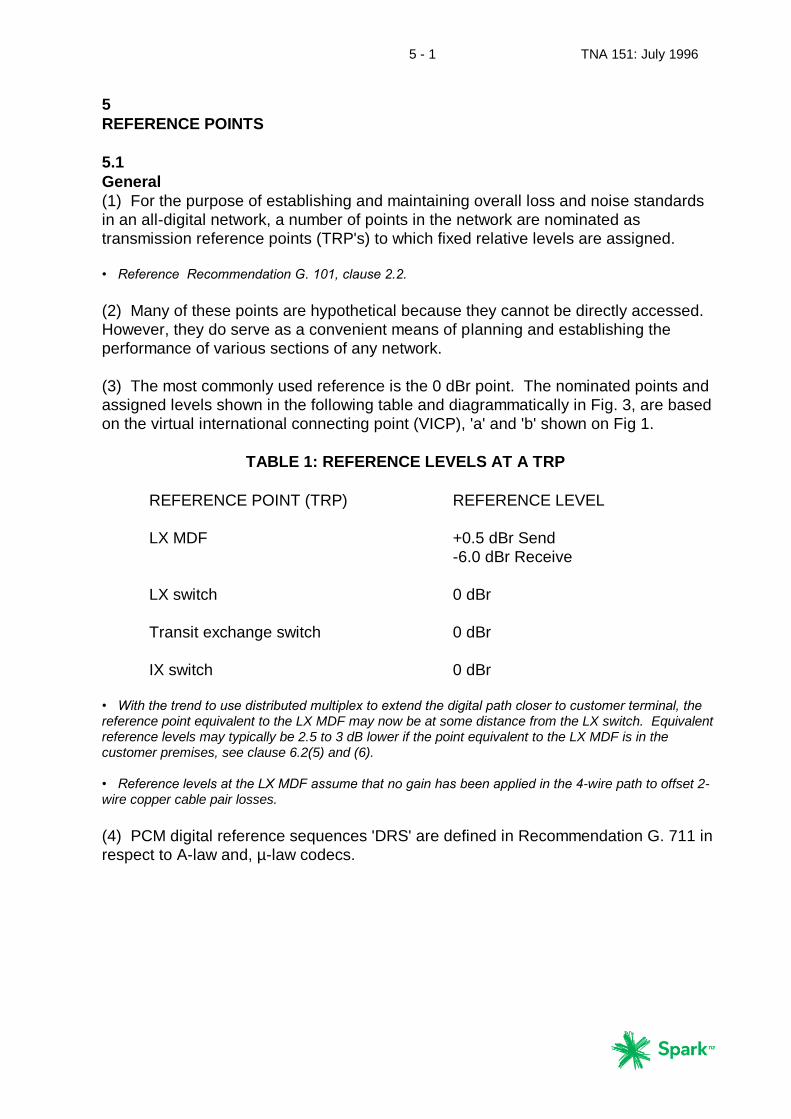
(3) The most commonly used reference is the 0 dBr point. The nominated points and
assigned levels shown in the following table and diagrammatically in Fig. 3, are based
on the virtual international connecting point (VICP), 'a' and 'b' shown on Fig 1.
TABLE 1: REFERENCE LEVELS AT A TRP
REFERENCE POINT (TRP) REFERENCE LEVEL
LX MDF +0.5 dBr Send
-6.0 dBr Receive
LX switch 0 dBr
Transit exchange switch 0 dBr
IX switch 0 dBr
• With the trend to use distributed multiplex to extend the digital path closer to customer terminal, the reference point equivalent to the LX MDF may now be at some distance from the LX switch. Equivalent reference levels may typically be 2.5 to 3 dB lower if the point equivalent to the LX MDF is in the customer premises, see clause 6.2(5) and (6). • Reference levels at the LX MDF assume that no gain has been applied in the 4-wire path to offset 2-wire copper cable pair losses.
(4) PCM digital reference sequences 'DRS' are defined in Recommendation G. 711 in
respect to A-law and, µ-law codecs.

5 - 2 TNA 151: July 1996
THIS PAGE IS INTENTIONALLY BLANK

5 - 3 TNA 151: July 1996
6 - 1 TNA 151: July 1996
6
OVERALL NETWORK TRANSMISSION PERFORMANCE
6.1
Transmission Plan
(1) For satisfactory end-to-end transmission where there is interworking between
networks, whether nationally or internationally, it is essential that performance l imits
be properly defined. This applies to the transmission performance between network
interfaces where customers can place calls that transit two or more networks.
• The telephone connection transmission performance objectives for national networks connected to the international network, either directly or indirectly, are outlined in Recommendations G. 101 and detailed in G. 120 to G. 135, G. 171 to G. 174.
(2) This section specifies the requirements for network transmission performance
applicable at particular interfaces. Other performance limits are given in Sections 7 -
11.
(3) The general transmission characteristics for circuits of international connections
are described by Recommendations G. 111 to 117. They cover loudness ratings,
noise limits, crosstalk, distortion, impairment and factors affecting stability and echo.
These Recommendations are used to define the New Zealand interface with the
international network.
(4) All international connections with New Zealand shall be equipped with devices at
the international gateway exchange to control echo originating in the New Zealand
network.
• Reference Recommendation G. 114, G. 131 and G. 165
6.2
Loudness rating (LR)
(1) The loudness ratings in the Telecom network have been apportioned as shown in
Fig 4:-
(a) Send and receive loudness rating of the telephone instrument (SLR and
RLR ) on a zero length line, and
(b) Circuit loudness rating (CLR) of the customer access circuit, and
(c) Switched circuit loss comprising the R and T pads.
• Principles and methods for determination of loudness ratings are given in Recommendations P. 76 to P. 79. • Minimum technical requirements, including loudness ratings for telephony products connected to the Telecom network are given in Telecom Specification PTC 200.
6 - 2 TNA 151: July 1996
(2) It is convenient to extend this concept to define performance through a network,
and particularly at the interface with other networks. This approach is used by the
ITU-T and is given in Recommendations G. 111 and G. 121.
(3) The loudness rating limits stated in this section are expressed for convenience
relative to a 0 dBr point. They include the customer access CLR and the effects of the
R and T pads shown in Figs. 3 and 4.
• Recommendation G. 121 describes the use of "R” and “T" pads and indicates values used by the former NZ Post Office in New Zealand as 7 dB and 0.5 dB respectively. The published 'R' value is however incorrect. The values actually used by Telecom, are 6.0 dB and 0.5 dB for the 'R' and 'T' pads respectively.
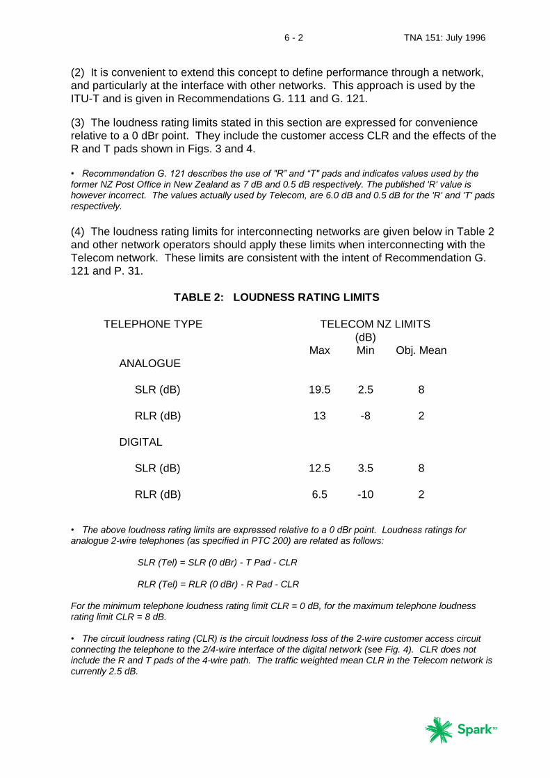
(4) The loudness rating limits for interconnecting networks are given below in Table 2
and other network operators should apply these limits when interconnecting with the
Telecom network. These limits are consistent with the intent of Recommendation G.
121 and P. 31.
TABLE 2: LOUDNESS RATING LIMITS
TELEPHONE TYPE TELECOM NZ LIMITS
(dB)
Max Min Obj. Mean
ANALOGUE
SLR (dB) 19.5 2.5 8
RLR (dB) 13 -8 2
DIGITAL
SLR (dB) 12.5 3.5 8
RLR (dB) 6.5 -10 2
• The above loudness rating limits are expressed relative to a 0 dBr point. Loudness ratings for analogue 2-wire telephones (as specified in PTC 200) are related as follows: SLR (Tel) = SLR (0 dBr) - T Pad - CLR RLR (Tel) = RLR (0 dBr) - R Pad - CLR For the minimum telephone loudness rating limit CLR = 0 dB, for the maximum telephone loudness rating limit CLR = 8 dB. • The circuit loudness rating (CLR) is the circuit loudness loss of the 2-wire customer access circuit connecting the telephone to the 2/4-wire interface of the digital network (see Fig. 4). CLR does not include the R and T pads of the 4-wire path. The traffic weighted mean CLR in the Telecom network is currently 2.5 dB.
6 - 3 TNA 151: July 1996
• Maximum SLR limit for analogue telephones exceeds ITU-T Recommendation G.121 nominal SLR maximum for average size countries by 3 dB. It is however acceptable to add manufacturing tolerances
(which can be as large as 3 dB) to nominal values when setting limits for individual telephone sets.
Further, the percentage of connections containing both limiting lines and limiting telephones is expected to be small. The maximum value of SLR is 14.5 dB for limiting customer access lines with a CLR of 8 dB when using telephones complying with the design target area indicated in PTC 200. • RLR limits include the full range of any receive volume control fitted. This applies to both analogue and digital telephones. The preferred RLR limit for telephones with no receive volume control is -2 dB. • Use of non-regulated analogue telephones is preferred and a regulation of less than 3 dB is recommended for new types of telephones. This reduces the possibility of overloading the encoder when being fed by limited current feed bridges.
(5) The 4-wire digital path is being extended to customers premises. PABX's and
multiplex equipment in the customers premises derive the 2-wire analogue circuit. To
meet objective loudness ratings the R and T pads are required in the 4-wire path,
together with an additional 2.5 to 3 dB of loss in either the 2-wire or 4-wire path, to
provide the objective OLR (overall loudness rating) and to reduce the effects of echo.
(6) Likewise cable television networks providing telephony will have the 2/4-wire
interface in the customers premises and will also need to incorporate the correct R
and T pads together with a 2.5 to 3 dB loss.
6.3
Overall loudness rating (OLR)
(1) The overall loudness rating of a telephone connection is simply the sum of the
SLR of one party, the RLR of the other party and any additional losses incurred,
including mismatch losses, over the connection between. If both SLR and RLR of the
respective parties are referred to the same 0 dBr reference point then:
OLR = SLR + RLR
This applies separately in each direction of transmission.
(2) ITU-T Recommendation G.111 notes that for connections under practical
conditions a suitable value of OLR in most cases seems to be 10 dB for the traffic
weighted mean. Further, a long term objective range of 8 - 12 dB for the traffic
weighted mean is specified. Networks should be designed such that at least 90 % of
call connections satisfy this objective requirement.
(3) The loudness ratings contained in Table 2 above are designed to meet these
objectives.
6.4
Sidetone
ITU-T specifies sidetone masking rating (STMR) as a measure of the sidetone loss as
experienced by the user of a telephone. The preferred range for STMR for 2-wire
telephone sets is 7 to 12 dB for a complete connection, and 15 5 dB for digital 4-wire
telephone sets for near-end introduced sidetone.

6 - 4 TNA 151: July 1996
• Telecom's impedance strategy and PTC stability requirements for telephones and other devices inherently limit sidetone. There is no mandatory STMR limit imposed for Telepermit purposes, but it is recommended that STMR for 2-wire telephones be no less than 7 dB. • Reference Recommendation G. 111 and G. 121 for sidetone experienced on 2-wire telephone sets. • The fundamental principles for determination of STMR are given in Recommendation P. 76.
6.5
Attenuation distortion
(1) In an all digital network, attenuation distortion can be expected to satisfy ITU-T
requirements if the requirements of section 9 of this document are satisfied.
• Reference Recommendation G. 113 and G. 132.
(2) The requirements for individual digital exchanges shall comply with
Recommendations Q. 552 and Q. 553.
6.6
Group delay distortion
(1) In an all digital network, group delay distortion can be expected to satisfy ITU-T
requirements if the requirements of section 9 of this document are satisfied.
• Reference Recommendation G. 113.
(2) For overall group delay distortion in a mixed analogue/digital network, the
requirements of Recommendation G. 133 shall be satisfied.
(3) The requirements for individual digital exchanges shall comply with
Recommendations Q. 552 and Q. 553.
6.7
Timing and synchronisation
Design objectives and performance limits for synchronisation and the control of timing,
jitter, wander, slip and bit errors in digital networks shall comply with
Recommendations G. 810 to G. 812 and G. 821 to G. 826.
7 - 1 TNA 151: July 1996
7
TRANSMISSION LOSS
7.1
Loss plan
(1) Any network can be regarded as a number of individual links connected together
in tandem to provide a connection between two terminal stations. In order to provide a
satisfactory overall network performance it is necessary to specify the performance
requirements for each type of individual link and switch making up that network.
(2) The losses on analogue customer lines are specified by the loudness rating limits
given in Section 6.
• The objective maximum loss on Telecom local access lines is 8 dB CLR. Other constraints placed on cable circuits may limit permitted maximum losses on many Telecom lines to less than 8 dB CLR.
7.2
Digital network
(1) A nominal loss of 0 dB is specified in the digital 4-wire path, see Fig 3.
(2) A fixed loss of 6.5 dB is specified between 2-wire analogue interfaces with the
digital network, 6 dB in the receive path and 0.5 dB in the send path (assuming that no
gain has been applied in the 4-wire path to offset 2-wire copper cable pair losses).
• Additional loss is required in either the 2-wire or 4-wire path if the 2-wire interface is in the customer's premises, ref clauses 6.2, (5) and (6) above.
(3) If digital customer loops are used (e.g. ISDN or digital PABX trunks) then the
connection has 0 dB loss to the customer premises. The digital telephone loudness
ratings given in Table 2 (Clause 6.2) apply if digital telephones are connected to such
customer loops. It is assumed that any additional loss required to meet the limits
given in Table 2 will be incorporated into the digital telephone instrument itself.

7 - 2 TNA 151: July 1996
THIS PAGE IS INTENTIONALLY BLANK
8 - 1 TNA 151: July 1996
8
NOISE AND CROSSTALK
8.1
Digital processes
(1) In an all digital network the predominant noise present is that produced by the
digital coding and decoding processes. Requirements for these are covered in
Section 10.
(2) The noise and crosstalk of individual digital exchanges shall comply with
Recommendations Q. 551 to Q. 553.
8.2
Analogue noise components
(1) In a predominantly all digital network analogue noise components are limited to
the analogue telephone and customer's local access line. Noise measurements are
made using a psophometer with telephone type weighting in accordance with
Recommendation O. 41.
(2) Local circuit noise, which is that produced by a combination of customer premises
equipment and the local access line, is measured at the local exchange MDF.
• Provisional limits are circuit noise -65 dBm and ground noise -5 dBm.
8.3
Crosstalk
In a predominantly digital network audible crosstalk is restricted to the 2-wire customer
access circuit. Linear crosstalk shall comply with G. 151.

8 - 2 TNA 151: July 1996
THIS PAGE IS INTENTIONALLY BLANK
9 - 1 TNA 151: July 1996
9
ECHO AND STABILITY
9.1 Echo
(1) Echo is not usually a problem in an all-digital network terminated with 4-wire
digital terminal devices. However, while some analogue 2-wire components including
telephones remain, it is necessary for all network operators to take the effects of echo
into account. Parameters which affect echo are impedance mismatch, circuit loss,
delay (or propagation time) due to distance and/or digital processes, and telephone
transmit and receive levels. It is noted that acoustic echo is a significant factor in the
operation of handsfree mobile cellular customer terminals.
(2) Noticeable echo is disturbing to telephone users. With short round-trip times
reflections are perceived as sidetone, rather than echo. However, reflections are
perceived as echo when round trip delay times exceed about 20 ms. This becomes
significant on long distance or international calls where signal delay causes the echo
to be much more noticeable to a telephone user.
(3) Also, the introduction of digital components into the international network has
accentuated the effect of echo because of processing delays inherent in digital coding
and decoding. Thus, in the mixed analogue/digital network which exists in the
international network, it is extremely important to limit both the cause of echo and the
effect it produces. This situation is likely to exist for several years yet.
• The effects of echo and method of measurement are described in Recommendation G. 122.
(4) The objective of this plan on international and national connections is to limit the
overall probability of objectionable echo being encountered to less than 1%, and to
tolerate a probability of not more than 10% in any specific situation. This is consistent
with Recommendation G. 131.
9.2
Impedance
(1) The major source of echo is signal reflections at impedance mismatches. These
can occur at both ends of a connection between the terminal customer loop and the
hybrid balance network. Assessment of this mismatch is achieved by measurement of
echo loss as indicated in Recommendation G. 122 (see also Fig. 4).
(2) To minimise mismatch Telecom specifies an objective standard impedance for the
input impedance of telephones, input impedance of digital switches, and balance
networks associated with 2-wire/4-wire hybrids. The objective standard impedance is
represented by a 370 Ω resistor in series with the parallel combination of a 620 Ω
resistor and a 310 nF capacitor (see Fig 5a). This impedance, which originated in the
British Telecom network, is commonly known as "BT 3".
• Telecom switches and transmission systems use a number of alternative balance networks from which the best match can be selected for individual customer line conditions. BT 3 is however an all round compromise and is now increasingly being used.
9 - 2 TNA 151: July 1996
9.3
Delay
(1) Consideration will be given to fitting echo control devices for national calls where
the delay within the Telecom network exceeds 10 ms mean one way propagation time
(MOPT).
(2) It is expected that any party which introduces significant additional delay into a
call will be responsible for the control of echo, even if the signal reflection which gives
rise to that echo is produced by customer equipment connected to a network operated
by another party.
(3) Echo control devices are used on all international calls as per Recommendation
G. 114. The following are the recommended limits for the mean one way propagation
times for any call through the national or international PSTN where appropriate echo
control devices, i.e. echo cancellers, are used:-
(a) 0 to 150 ms, acceptable for most user applications.
(b) 150 to 400 ms acceptable providing the impact on transmission quality of
user applications is recognised.
(c) above 400 ms, unacceptable for network planning purposes.
(4) For Recommendation G. 114 to be achieved, there should not be more than one
satellite link used in any given call through the national or international network.
However it is recognised that for special cases a second satellite link may be used for
domestic calls, i.e. Chatham Islands and Scott Base.
(5) The contribution of individual network components to the one-way propagation
time is given in Recommendation G. 114, Table A.1.
9.4
Echo loss
(1) Echo is made up of several components. The echo loss at the 2w/4w point, any
impedance mismatches due to customer access circuit discontinuities, and the return
loss at the customer’s 2-wire termination. This is further contributed to by any 2w/4w
conversions within the customer’s premises.
(2) The minimum echo loss at any transmission system 2-wire analogue port is
measured at the four-wire path (0 dBr point) with the two-wire port terminated in the
nominal impedance (BT3) and with adjusting pads set to zero.
(3) The minimum echo loss shall be no less than 12 dB in the band 300 to 600 Hz
and no less than 15 dB in the band 600 to 3400 Hz.
(4) To ensure adequate performance of the hybrid and its balance network, the
terminal balance return loss (TBRL) is measured, as in (2) against BT3, shall be no
less than:-
9 - 3 TNA 151: July 1996
(a) 13 dB in the band 300 to 500 Hz, and
(b) 18 dB in the band 500 to 2500 Hz, and
(c) 14 dB in the band 2500 to 3400 Hz.
• Reference Recommendation G. 712 clauses 5.2 and 16.1.
(5) The reflections caused by line mismatches are kept to a minimum by appropriate
design and are not usually significant in comparison with echo loss and return loss.
(6) The minimum return loss of the telephone against the impedance BT 3 shall be no
less than 10 dB at any frequency in the band 200 to 1000 Hz or 12 dB in the band
1000 to 3400 Hz. The echo return loss of the telephone against the impedance BT3
shall be no less than 14 dB.
• Reference PTC 200.
9.5
Stability loss
(1) Instability is the specific result of echo when signals can recirculate without being
diminished because the sum of the losses around the four-wire loop is less than the
sum of the gains. To prevent instability, it is necessary to ensure that there is an
adequate net loss around any four-wire path.
(2) To avoid instability on international and national connections, it is necessary to
limit the risk of an echo loss (a - b in Fig. 1) of 0 dB or less at any frequency 0 - 4 kHz.
The objective of this plan is to ensure that the probability of such a loss occurring
does not exceed 6 in 1000 calls.
(3) Use of R and T pads as stated in clause 6.2 normally ensures that an adequate
stability loss margin is maintained. Application of gain to offset losses in the 2-wire
customer access circuit reduces both stability and echo margins (see clause 9.1).
• Application of gain in the 4-wire path reduces stability and echo loss margins by twice the level of gain applied. Effect of gain applied in the 2-wire path is less but of the same order. However, amplifiers placed in the two wire path may additionally become unstable during call set up and clear down, hence it is preferred that gain be located in the 4-wire path. • Gain applied in either the 2-wire or 4-wire path to offset loss in new 2-wire copper cable customer access circuits is limited to a maximum of 4 dB. Existing customer access circuits may have up to 6 dB of gain applied. • Echo control devices typically require an echo loss (a - b) of 6 dB or greater for effective operation.
(4) Digital transmission systems forming separate permanent 4-wire loops in a
connection shall have a 2-wire to 2-wire loss of 2 dB
• Gain is not applied in conjunction with transmission systems to offset loss in copper cable extensions.
9 - 4 TNA 151: July 1996
9.6
Telephone transmit and receive levels
(1) Maximum telephone transmit and receive levels are specified in Section 6.
Excessive transmit and/or receive levels will result in the perception of any echo
present being enhanced.
• Excessive send levels also result in overloading of encoders. Excessive receive loudness levels increase the contrast in loudness with other telephones and may reduce listener comfort. • Receive volume controls provided on many telephones can be used to reduce the perception of any echo effects present by being turned down.
(2) The transmission performance of analogue-connected CPE is specified in
Specification PTC 200: 1996.
10 - 1 TNA 151: July 1996
10
DIGITAL TRANSMISSION IMPAIRMENT
10.1
Quantising distortion units (QDU's)
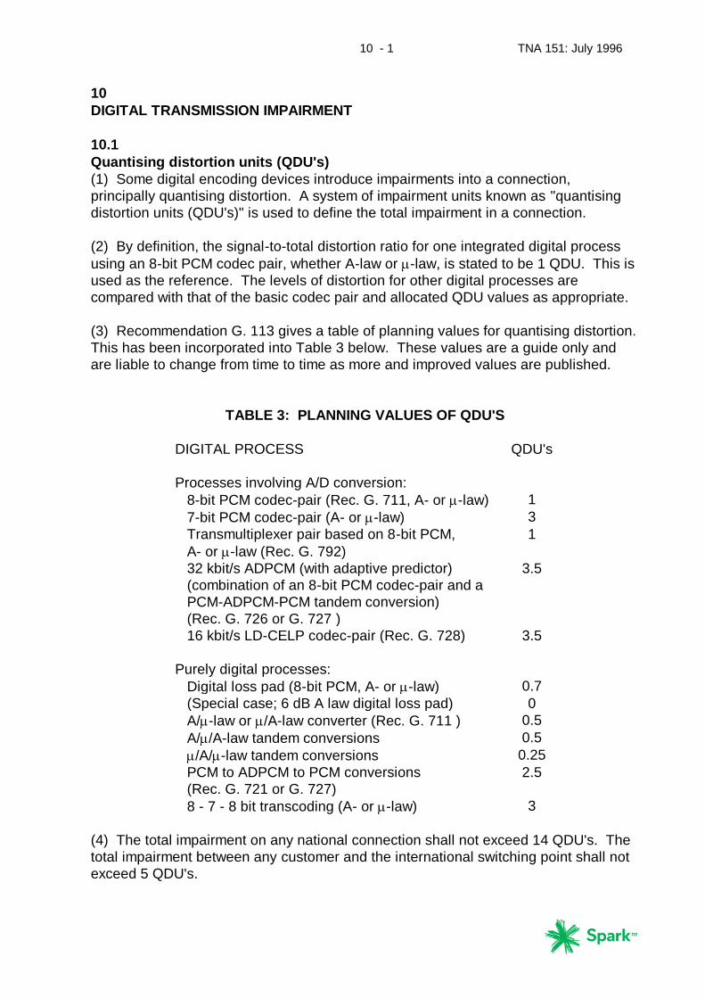
(1) Some digital encoding devices introduce impairments into a connection,
principally quantising distortion. A system of impairment units known as "quantising
distortion units (QDU's)" is used to define the total impairment in a connection.
(2) By definition, the signal-to-total distortion ratio for one integrated digital process
using an 8-bit PCM codec pair, whether A-law or -law, is stated to be 1 QDU. This is
used as the reference. The levels of distortion for other digital processes are
compared with that of the basic codec pair and allocated QDU values as appropriate.
(3) Recommendation G. 113 gives a table of planning values for quantising distortion.
This has been incorporated into Table 3 below. These values are a guide only and
are liable to change from time to time as more and improved values are published.
TABLE 3: PLANNING VALUES OF QDU'S
DIGITAL PROCESS QDU's
Processes involving A/D conversion:
8-bit PCM codec-pair (Rec. G. 711, A- or -law) 1
7-bit PCM codec-pair (A- or -law) 3
Transmultiplexer pair based on 8-bit PCM,
A- or -law (Rec. G. 792)
1
32 kbit/s ADPCM (with adaptive predictor)
(combination of an 8-bit PCM codec-pair and a
PCM-ADPCM-PCM tandem conversion)
(Rec. G. 726 or G. 727 )
3.5
16 kbit/s LD-CELP codec-pair (Rec. G. 728) 3.5
Purely digital processes:
Digital loss pad (8-bit PCM, A- or -law) 0.7
(Special case; 6 dB A law digital loss pad) 0
A/-law or /A-law converter (Rec. G. 711 ) 0.5
A//A-law tandem conversions 0.5
/A/-law tandem conversions 0.25
PCM to ADPCM to PCM conversions
(Rec. G. 721 or G. 727)
2.5
8 - 7 - 8 bit transcoding (A- or -law) 3
(4) The total impairment on any national connection shall not exceed 14 QDU's. The
total impairment between any customer and the international switching point shall not
exceed 5 QDU's.
10 - 2 TNA 151: July 1996
(5) The total impairment contribution by any customer system or private network from
which calls are extended to or received from the PSTN shall not exceed 3.5 QDU's.
• Ref. PTC 110.
(6) The total impairment contributed by any interconnecting network between the
customer and point of interconnection shall not exceed 3 QDU's.
• In theory (5) and (6) above could result in 6.5 QDU's being added between the customer and the international switching point. However this is expected to be rare in practice. Most connections will only encounter 0.5 or 1.5 QDU's within the Telecom network to the international switching point, or to the point of interconnection with other networks.
(7) Certain multiple synchronous digital conversions can be assigned a total
impairment equal to that of a single digital conversion if the following conditions are
satisfied (see Recommendation G. 113):-
(a) All conversions are synchronous, and
(b) the same algorithm is used throughout, and
(c) Only 64 kbit/s/s PCM is used between conversions.
• One example of this is ADPCM, where an allocation of 2.5 QDU's can be made for a chain consisting of PCM - ADPCM - PCM - ADPCM - PCM conversions, if it satisfies the above conditions.
(8) It is noted that the use of QDU’s is under review by ITU-T. The intent of this Plan
is to generally limit the use of sub 64 kbit/s encoding processes to one encoding pair
within cellular mobile networks, to one encoding/decoding pair within private networks,
and to one encoding/decoding pair within the Telecom PSTN or national PSTN
networks of other operators.
• One encoding/decoding pair is taken to include a number of systems in tandem where the additional encoding/decoding stages in the chain do not introduce any further degradation. An example is ADPCM, see sub-clause (7) above.

11 - 1 TNA 151: July 1996
11
OTHER NETWORKS
11.1
General
(1) When PABXs or other devices/services (e.g. radio telephone systems) are
connected to function as a specialised network associated with the Telecom PSTN,
the combined performance of the PSTN and the specialised network shall be within
the limits specified in this document.
(2) While operators of private networks which are in no way connected to a public
network need not comply with (1) above, it is important to note that such networks
rarely remain independent of a public network. In the circumstances, compliance with
the requirements of this Plan should ensure adequate performance if connection to a
public network occurs at a future date.
• See PTC 110.
11.2
PABX networks
(1) Any PABX networks connected to the PSTN shall comply with the ITU-T
Recommendations as follows:-
(a) Analogue or mixed analogue/digital PABX networks shall comply with
Recommendation G. 171, clauses 1 - 9.
(b) All digital PABX networks shall comply with Recommendation G. 171,
clauses 10 and 11.
(2) For all PABX networks, the loudness rating between any PABX extension
telephone and the PSTN exchange to which it is connected shall be within the limits
specified in Section 6. This requirement applies whether the PABX is stand-alone or
is networked with other PABX's.
• Reference Recommendation G. 171, clauses 7.& 11.
(3) For digital PABX's, the recommended TRP (known as the "Ports TRP" or PTRP) is
0 dBr, the same as for the LX.
• A PTRP of 0 dBr simplifies digital connection of the PABX to the PSTN. • Where analogue trunks are used between PABX and LX, the 0 dBr points are reference points only. In practice they will usually be at different levels.
(4) Echo is a frequent problem in mixed analogue/digital PABX networks. It is
therefore important that echo be carefully controlled when such a network is
connected to the PSTN, see Section 9.
• Reference Recommendation G. 171, clause 11.
11 - 2 TNA 151: July 1996
11.3
Other Telecom Networks
(1) Telecom has two mobile networks that interconnect with the Telecom PSTN:-
(a) cellular mobile telephone network.
(b) land mobile radio dispatch network.
The transmission aspects of these networks are defined in their separate plans.
(2) The transmission aspects of future Digital Public Land Mobile Networks as defined
by the ITU-T are covered in Recommendation G. 173.
(3) Network transmission plans will evolve to incorporate future services and
applications like personal communications service (PCS) and universal personal
telecommunications (UPT), but are expected to be based on this Plan.
12 - 1 TNA 151: July 1996
12
NETWORK ASSISTANCE OPERATOR'S CIRCUITS
12.1
Loudness rating
The objective operator circuit loudness ratings referenced to a 0 dBr point are as
follows:
Max Min Obj. Mean
Send loudness rating SLR (dB) 11.5 3.5 8
Receive loudness rating RLR (dB) 6.5 -10 2
• The RLR includes the full range of receive volume control fitted.
12.2
Connection
(1) The operator's circuit in a digital exchange is connected at a 0 dBr transmission
reference point and as shown in Fig. 6.
(2) Any additional loss introduced into a connection by the operator's circuit shall not
exceed the following:
Monitoring condition 0.3 dB
Speaking condition 1.0 dB
(3) Connection of the operator's circuit shall not degrade the return loss requirements
stated in Section 9, see Fig. 6.

12 - 2 TNA 151: July 1996
THIS PAGE IS INTENTIONALLY BLANK
TNA 151: July 1996
APP1 - 1
APPENDIX 1
Excerpts from:-
FINAL ACTS
OF THE WORLD ADMINISTRATIVE
TELEGRAPH AND TELEPHONE
CONFERENCE (WATTC-88)
MELBOURNE, 1988
NOTE: Emphasis has been added to the key clauses of this document which
relate to the Telecom New Zealand Transmission Plan
TNA 151: July 1996
APP1 - 2
INTERNATIONAL TELECOMMUNICATION REGULATIONS
PREAMBLE
While the sovereign right of each country to regulate its telecommunications is fully
recognised, the provisions of the present Regulations supplement the international
Telecommunications Convention, with a view to attaining the purposes of the
lnternational Telecommunication Union in promoting the development of
telecommunication services and their most efficient operation while harmonising the
development of facilities for world-wide telecommunications.
Article 1
PURPOSE AND SCOPE OF THE REGULATIONS
1.1.1 These Regulations establish general principles which relate to the provision
and operation of international telecommunication services offered to the public as well
as to the underlying international telecommunication transport means used to provide
such services. They also set rules applicable to administrations•.
1.1.2 These Regulations recognise in Article 9 the right of Members to allow special
arrangements.
1.2 In these Regulations, "the public" is used in the sense of the population,
including governmental and legal bodies.
1.3 These Regulations are established with a view to facilitating global:
interconnection and interoperability of telecommunication facilities and to promoting
the harmonious development and efficient operation of technical facilities, as well as
the efficiency, usefulness and availability to the public of international
telecommunication services.
1.4 References to CClTT Recommendations and lnstructions in these Regulations
are not to be taken as giving to those Recommendations and lnstructions the same
legal status as the Regulations.
1.5 Within the framework of the present Regulations, the provision and operation of
international telecommunication services in each relation pursuant to mutual
agreement between administrations•.
1.6 In impIementing the principles of these Regulations, administrations•
should comply with, to the greatest extent practicable, the relevant CCITT
Recommendations, including any Instructions forming part of or derived from
these Recommendations.
TNA 151: July 1996
APP1 - 3
1.7 (a) These Regulations recognise the right of any Member, subject to
national law and should it decide to do so, to require that
administrations and private operating agencies, which operate in its
territory and provide an international telecommunication service to the
public, be authorised by that Member.
(b) The Member concerned shall, as appropriate, encourage the
application of relevant CCITT Recommendations by such service
providers.
(c) The Members, where appropriate, shall cooperate in implementing the
International Telecommunications Regulations (For interpretation, also
see Resolution No. PL/2).
1.8 The Regulations shall apply, regardless of the means of transmission used, so
far as the Radio Regulations do not provide otherwise.
Article 2
2.8 Accounting rate: The rate agreed between administrations• in a given relation
that is used for the establishment of international accounts.
2.9 Connection charge: The charge established and collected by an
administration• from its customers for the use of an international telecommunication
service.
2,10 Instructions: A collection of provisions drawn from one or more CCITT
Recommendations dealing with practical operational procedures for the handling of
telecommunication traffic (e.g. acceptance, transmission, accounting).
TNA 151: July 1996
APP1 - 4
Article 3
INTERNATIONAL NETWORK
3.1 Members shall ensure that administrations• cooperate in the
establishment, operation and maintenance of the international network to
provide a satisfactory quality of service.
3.2 Administrations• shall endeavour to provide sufficient telecommunication
facilities to meet the requirements of and demand for international telecommunication
services.
3.3 Administrations• shall determine by mutual agreement which international
routes are to be used. Pending agreement and provided that there is no direct route
existing between the terminal administrations• concerned, the origin administration
has the choice to determine the routing of its outgoing telecommunication traffic,
taking into account the interests of the relevant transit and destination
administrations•.
3.4 Subject to national law, any user, by having access to the international network
established by an administration•, has the right to send traffic. A satisfactory quality
of service should be maintained to the greatest extent practicable,
corresponding to relevant CCITT Recommendations.
TNA 151: July 1996
APP1 - 5
Article 4
INTERNATlONAL TELECOMMUNICATION SERVICES
4.1 Members shall promote the implementation of international telecommunication
services and shall endeavour to make such services generally available to the public
in their national network(s).
4.2 Members shall ensure that administrations• cooperate within the framework of
these Regulations to provide by mutual agreement, a wide range of international
telecommunication services which should conform, to the greatest extent
practicable, to the relevant CCITT Recommendations.
4.3 Subject to national law, Members shall endeavour to ensure that
administrations• provide and maintain, to the greatest extent practicable, a minimum
quality of service corresponding to relevant CCITT Recommendations with
respect to:
(a) access to the international network by users using terminals which are
permitted to be connected to the network and which do not cause harm
to technical facilities and personnel;
(b) international telecommunication facilities and services available to
customers for their dedicated use;
(c) at least a form of telecommunication which is reasonably accessible to
the public, including those who may not be subscribers to a specific
telecommunication service; and
(d) a capability for interworking between different services, as appropriate,
to facilitate international communications.
• or recognised private operating agency(ies).
END OF APPENDIX 1

TNA 151: July 1996
APP1 - 6
THIS PAGE IS INTENTIONALLY BLANK

TNA 151: July 1996
FIGS - 1