Embed Size (px)
Citation preview
Reference Number:336069-007US
Intel® C620 Series Chipset Platform Controller Hub Specification Update
April 2019
2 Intel® C620 Series Chipset Platform Controller HubApril 2019 Specification Update
Legal Lines and DisclaimersIntel technologies’ features and benefits depend on system configuration and may require enabled hardware, software or service activation. Learn more at Intel.com, or from the OEM or retailer.No computer system can be absolutely secure. Intel does not assume any liability for lost or stolen data or systems or any damages resulting from such losses.You may not use or facilitate the use of this document in connection with any infringement or other legal analysis concerning Intel products described herein. You agree to grant Intel a non-exclusive, royalty-free license to any patent claim thereafter drafted which includes subject matter disclosed herein.No license (express or implied, by estoppel or otherwise) to any intellectual property rights is granted by this document.The products described may contain design defects or errors known as errata which may cause the product to deviate from published specifications. Current characterized errata are available on request.Intel disclaims all express and implied warranties, including without limitation, the implied warranties of merchantability, fitness for a particular purpose, and non-infringement, as well as any warranty arising from course of performance, course of dealing, or usage in trade.Copies of documents which have an order number and are referenced in this document may be obtained by calling 1-800-548-4725 or by visiting www.intel.com/design/literature.htm.Intel and the Intel logo are trademarks of Intel Corporation in the U.S. and/or other countries.*Other names and brands may be claimed as the property of others.Copyright © 2019, Intel Corporation. All Rights Reserved.
Contents
Intel® C620 Series Chipset Platform Controller Hub 3Specification Update April 2019
Contents
Revision History ........................................................................................................4
Preface ......................................................................................................................5
Summary Tables of Changes......................................................................................6
Identification Information ....................................................................................... 10
Errata ...................................................................................................................... 11
Specification Changes.............................................................................................. 26
Specification Clarifications ...................................................................................... 27
Documentation Changes .......................................................................................... 28
Revision History
4 Intel® C620 Series Chipset Platform Controller HubApril 2019 Specification Update
Revision History
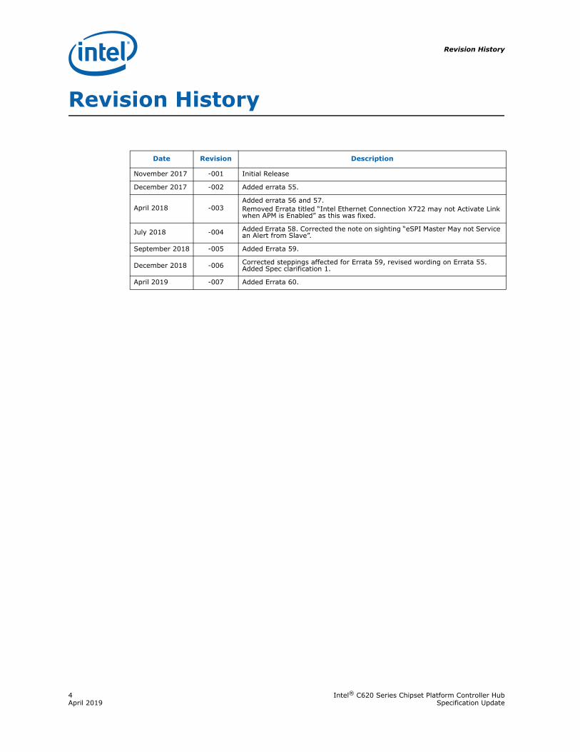
Date Revision Description
November 2017 -001 Initial Release
December 2017 -002 Added errata 55.
April 2018 -003Added errata 56 and 57.Removed Errata titled “Intel Ethernet Connection X722 may not Activate Link when APM is Enabled” as this was fixed.
July 2018 -004 Added Errata 58. Corrected the note on sighting “eSPI Master May not Service an Alert from Slave”.
September 2018 -005 Added Errata 59.
December 2018 -006 Corrected steppings affected for Errata 59, revised wording on Errata 55. Added Spec clarification 1.
April 2019 -007 Added Errata 60.
Intel® C620 Series Chipset Platform Controller Hub 5Specification Update April 2019
Preface
Preface
This document is an update to the specifications contained in the Affected Documents table below. This document is a compilation of device and documentation errata, specification clarifications and changes. It is intended for hardware system manufacturers and software developers of applications, operating systems, or tools.
Information types defined in Nomenclature are consolidated into the specification update and are no longer published in other documents.
This document may also contain information that was not previously published.
Affected Documents
NomenclatureErrata are design defects or errors. These may cause the Product Name’s behavior to deviate from published specifications. Hardware and software designed to be used with any given stepping must assume that all errata documented for that stepping are present on all devices.
Specification Changes are modifications to the current published specifications. These changes will be incorporated in any new release of the specification.
Specification Clarifications describe a specification in greater detail or further highlight a specification’s impact to a complex design situation. These clarifications will be incorporated in any new release of the specification.
Documentation Changes include typos, errors, or omissions from the current published specifications. These will be incorporated in any new release of the specification.
Note: Errata remain in the specification update throughout the product’s lifecycle, or until a particular stepping is no longer commercially available. Under these circumstances, errata removed from the specification update are archived and available upon request. Specification changes, specification clarifications and documentation changes are removed from the specification update when the appropriate changes are made to the appropriate product specification or user documentation (datasheets, manuals, and so forth).
Document Title Document Number/Location
Intel® C620 Series Chipset Platform Controller Hub Datasheet 336067
Summary Tables of Changes
6 Intel® C620 Series Chipset Platform Controller HubApril 2019 Specification Update
Summary Tables of Changes
The following tables indicate the errata, specification changes, specification clarifications, or documentation changes which apply to the Product Name product. Intel may fix some of the errata in a future stepping of the component, and account for the other outstanding issues through documentation or specification changes as noted. These tables uses the following notations:
Codes Used in Summary Tables
Stepping
X: Errata exists in the stepping indicated. Specification Change or Clarification that applies to this stepping.
(No mark)
or (Blank box): This erratum is fixed in listed stepping or specification change does not apply to listed stepping.
Page
(Page): Page location of item in this document.
Status
Doc: Document change or update will be implemented.
Plan Fix: This erratum may be fixed in a future stepping of the product.
Fixed: This erratum has been previously fixed.
No Fix: There are no plans to fix this erratum.
Row
Change bar to left of table row indicates this erratum is either new or modified from the previous version of the document.
Intel® C620 Series Chipset Platform Controller Hub 7Specification Update April 2019
Summary Tables of Changes
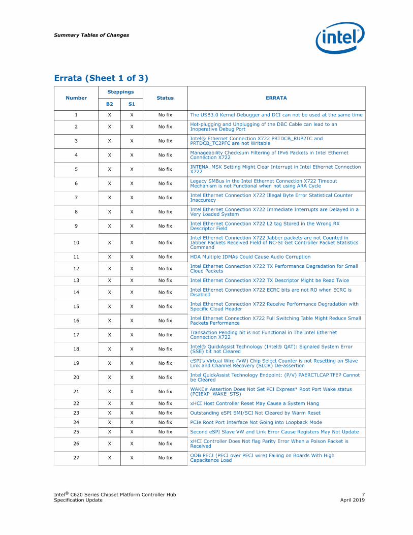
Errata (Sheet 1 of 3)
NumberSteppings
Status ERRATAB2 S1
1 X X No fix The USB3.0 Kernel Debugger and DCI can not be used at the same time
2 X X No fix Hot-plugging and Unplugging of the DBC Cable can lead to an Inoperative Debug Port
3 X X No fix Intel® Ethernet Connection X722 PRTDCB_RUP2TC and PRTDCB_TC2PFC are not Writable
4 X X No fix Manageability Checksum Filtering of IPv6 Packets in Intel Ethernet Connection X722
5 X X No fix INTENA_MSK Setting Might Clear Interrupt in Intel Ethernet Connection X722
6 X X No fix Legacy SMBus in the Intel Ethernet Connection X722 Timeout Mechanism is not Functional when not using ARA Cycle
7 X X No fix Intel Ethernet Connection X722 Illegal Byte Error Statistical Counter Inaccuracy
8 X X No fix Intel Ethernet Connection X722 Immediate Interrupts are Delayed in a Very Loaded System
9 X X No fix Intel Ethernet Connection X722 L2 tag Stored in the Wrong RX Descriptor Field
10 X X No fixIntel Ethernet Connection X722 Jabber packets are not Counted in Jabber Packets Received Field of NC-SI Get Controller Packet Statistics Command
11 X X No fix HDA Multiple IDMAs Could Cause Audio Corruption
12 X X No fix Intel Ethernet Connection X722 TX Performance Degradation for Small Cloud Packets
13 X X No fix Intel Ethernet Connection X722 TX Descriptor Might be Read Twice
14 X X No fix Intel Ethernet Connection X722 ECRC bits are not RO when ECRC is Disabled
15 X X No fix Intel Ethernet Connection X722 Receive Performance Degradation with Specific Cloud Header
16 X X No fix Intel Ethernet Connection X722 Full Switching Table Might Reduce Small Packets Performance
17 X X No fix Transaction Pending bit is not Functional in The Intel Ethernet Connection X722
18 X X No fix Intel® QuickAssist Technology (Intel® QAT): Signaled System Error (SSE) bit not Cleared
19 X X No fix eSPI’s Virtual Wire (VW) Chip Select Counter is not Resetting on Slave Link and Channel Recovery (SLCR) De-assertion
20 X X No fix Intel QuickAssist Technology Endpoint: (P/V) PAERCTLCAP.TFEP Cannot be Cleared
21 X X No fix WAKE# Assertion Does Not Set PCI Express* Root Port Wake status (PCIEXP_WAKE_STS)
22 X X No fix xHCI Host Controller Reset May Cause a System Hang
23 X X No fix Outstanding eSPI SMI/SCI Not Cleared by Warm Reset
24 X X No fix PCIe Root Port Interface Not Going into Loopback Mode
25 X X No fix Second eSPI Slave VW and Link Error Cause Registers May Not Update
26 X X No fix xHCI Controller Does Not flag Parity Error When a Poison Packet is Received
27 X X No fix OOB PECI (PECI over PECI wire) Failing on Boards With High Capacitance Load
Summary Tables of Changes
8 Intel® C620 Series Chipset Platform Controller HubApril 2019 Specification Update
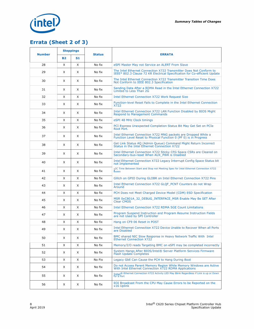
28 X X No fix eSPI Master May not Service an ALERT From Slave
29 X X No fix The Intel Ethernet Connection X722 Transmitter Does Not Conform to IEEE* 802.3 Clause 72 KR Electrical Specification for Co-efficient Update
30 X X No fix The Intel Ethernet Connection X722 Transmitter Transition Time Does Not Conform to IEEE 802.3 Specification
31 X X No fix Sending Data After a RDMA Read in the Intel Ethernet Connection X722 Limited to Less Than 2G
32 X X No fix Intel Ethernet Connection X722 Work Request Size
33 X X No fix Function-level Reset Fails to Complete in the Intel Ethernet Connection X722
34 X X No fix Intel Ethernet Connection X722 LAN Function Disabled by BIOS Might Respond to Management Commands
35 X X No fix eSPI 48 MHz Clock timings
36 X X No fix PCI Express Unexpected Completion Status Bit May Get Set on PCIe Root Port.
37 X X No fix Intel Ethernet Connection X722 MNG packets are Dropped While a Function Level Reset to Physical Function 0 (PF 0) is in Progress
38 X X No fix Get Link Status AQ (Admin Queue) Command Might Return Incorrect Status in the Intel Ethernet Connection X722
39 X X No fix Intel Ethernet Connection X722 Sticky CFG Space CSRs are Cleared on Secondary-bus-reset When AUX_PWR is Disabled
40 X X No fix Intel Ethernet Connection X722 Legacy Interrupt Config Space Status bit not Implemented
41 X X No fix I2C Time Between Start and Stop not Meeting Spec for Intel Ethernet Connection X722 Buses
42 X X No fix Glitch on GPIO During GLOBR on Intel Ethernet Connection X722 Pins
43 X X No fix Intel Ethernet Connection X722 GLQF_PCNT Counters do not Wrap Around
44 X X No fix PCH Does not Meet Charged Device Model (CDM) ESD Specification
45 X X No fix MSR 0xC801A_32_DEBUG_INTERFACE_MSR Enable May Be SET After Clear CMOS
46 X X No fix Intel Ethernet Connection X722 RDMA SGE Count Limitations
47 X X No fix Program Suspend Instruction and Program Resume Instruction Fields are not Used by SPI Controller
48 X X No fix Hang on CF9 06 Reset in POST
49 X X No fix Intel Ethernet Connection X722 Device Unable to Recover When all Ports are Disabled
50 X X No fix BMC shared NIC Slow Response in Heavy Network Traffic With Intel Ethernet Connection X722
51 X X No fix Memory/I/O reads Targeting BMC on eSPI may be completed incorrectly
52 X X No fix System Hangs After BIOS/Intel® Server Platform Services Firmware Flash Update Completes
53 X X No Fix Legacy GbE Can Cause the PCH to Hang During Boot
54 X X No fix Do not Access Parent Memory Region While Memory Windows are Active With Intel Ethernet Connection X722 RDMA Applications
55 X X No fix Intel® Ethernet Connection X722 Activity LED May Blink Regardless if Link is up or Down for a Port
56 X X No fix EOI Broadcast From the CPU May Cause Errors to be Reported on the x16 Uplink
Errata (Sheet 2 of 3)
NumberSteppings
Status ERRATAB2 S1
Intel® C620 Series Chipset Platform Controller Hub 9Specification Update April 2019
Summary Tables of Changes
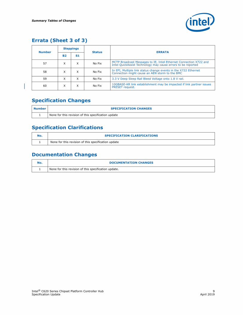
57 X X No Fix MCTP Broadcast Messages to IE, Intel Ethernet Connection X722 and Intel QuickAssist Technology may cause errors to be reported
58 X X No Fix In EFI, Multiple link status change events in the X722 Ethernet Connection might cause an AEN storm to the BMC
59 X X No Fix 3.3 V Deep Sleep Rail Bleed Voltage onto 1.8 V rail.
60 X X No Fix 10GBASE-KR link establishment may be impacted if link partner issues PRESET request.
Specification ChangesNumber SPECIFICATION CHANGES
1 None for this revision of this specification update
Specification ClarificationsNo. SPECIFICATION CLARIFICATIONS
1 None for this revision of this specification update
Documentation ChangesNo. DOCUMENTATION CHANGES
1 None for this revision of this specification update.
Errata (Sheet 3 of 3)
NumberSteppings
Status ERRATAB2 S1
Identification Information
10 Intel® C620 Series Chipset Platform Controller HubApril 2019 Specification Update
Identification Information
Component Identification via Programming InterfaceSee the Intel C620 series Chipset Platform Controller Datasheet for this information.
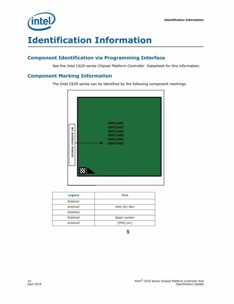
Component Marking InformationThe Intel C620 series can be identified by the following component markings.
:
§
Legend Text
Gripline1
Gripline2 Intel {R} SKU
Gripline3
Gripline4 Sspec number
Gripline5 {FPO] [e1}
Intel® C620 Series Chipset Platform Controller Hub 11Specification Update April 2019
Errata
Errata
1. The USB3.0 Kernel Debugger and DCI can not be used at the same timeProblem: When both DCI and kernel debugger are enabled, DCI will take precedence over the
kernel debugger. This keeps kernel debugger from being used.Implication: BIOS may not be able to use the USB 3.0 kernel debugger if DCI is enabled.Workaround: Disabling DCI via BIOS if you want to use the USB3.0 kernel debugger.Status: No Fix.
2. Hot-plugging and Unplugging of the DBC Cable can lead to an Inoperative Debug Port
Problem: If the DBC cable is plugged and unplugged while in the S0 state, in approximately oneout of 100 cases it is possible to get into a condition where the debug port gets to astate where it locks up and only a power cycle will restore functionality.
Implication: Plugging and unplugging the DBC cable while the system is in S0 state can lead to aninoperative debug port.
Workaround: Connect or disconnect the cable when the system is off.Status: Will not fix. The use case of hot-plugging the cable is not a standard operating
procedure for debugging with the DBC cable.
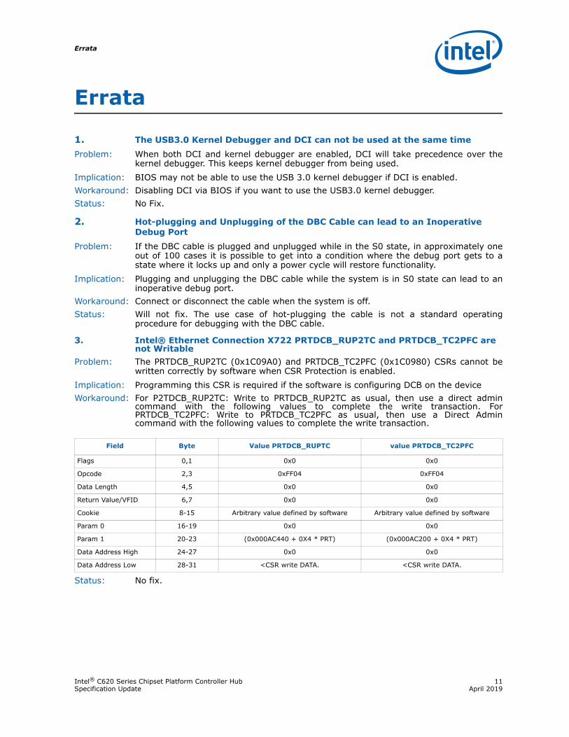
3. Intel® Ethernet Connection X722 PRTDCB_RUP2TC and PRTDCB_TC2PFC are not Writable
Problem: The PRTDCB_RUP2TC (0x1C09A0) and PRTDCB_TC2PFC (0x1C0980) CSRs cannot bewritten correctly by software when CSR Protection is enabled.
Implication: Programming this CSR is required if the software is configuring DCB on the deviceWorkaround: For P2TDCB_RUP2TC: Write to PRTDCB_RUP2TC as usual, then use a direct admin
command with the following values to complete the write transaction. ForPRTDCB_TC2PFC: Write to PRTDCB_TC2PFC as usual, then use a Direct Admincommand with the following values to complete the write transaction.
Status: No fix.
Field Byte Value PRTDCB_RUPTC value PRTDCB_TC2PFC
Flags 0,1 0x0 0x0
Opcode 2,3 0xFF04 0xFF04
Data Length 4,5 0x0 0x0
Return Value/VFID 6,7 0x0 0x0
Cookie 8-15 Arbitrary value defined by software Arbitrary value defined by software
Param 0 16-19 0x0 0x0
Param 1 20-23 (0x000AC440 + 0X4 * PRT) (0x000AC200 + 0X4 * PRT)
Data Address High 24-27 0x0 0x0
Data Address Low 28-31 <CSR write DATA. <CSR write DATA.
Errata
12 Intel® C620 Series Chipset Platform Controller HubApril 2019 Specification Update
4. Manageability Checksum Filtering of IPv6 Packets in Intel Ethernet Connection X722
Problem: The IPv6 checksum calculation could be incorrect for received packets that containeither a Routing (type 2) Extension Header or a Destination Options Extension headerthat includes a home address option.
Implication: If the manageability filtering is configured to drop packets with checksum errors, IPv6manageability packets with the extension headers described above could be incorrectlydropped.
Workaround: Do not enable checksum filtering for manageability if the IPv6 Extension Headersdescribed above are used on manageability traffic.
For SMBus: The Enable Xsum Filtering to MNG bit should be 0b in the Update Management Receive filter parameters command, and in the Set Common Filters Receive Control Bytes command if these commands are used.
For NC-SI: Do not use the Enable Checksum Offloading command (Intel OEM command 0x23)
Status: No fix.
5. INTENA_MSK Setting Might Clear Interrupt in Intel Ethernet Connection X722 Problem: A write access to an xxINT_DYN_CTLx CSR with INTENA_MSK bit (bit31) ==1’b0 clears
the corresponding interrupt bit in the PBA array.Implication: There is a possibility of missing an interrupt. However, current Intel software
implementation has this bit set to 1 except when enabling or disabling interrupts. Workaround: INTENA_MSK should be set in all CSR write accesses other than INTENA bit change. Status: No fix
6. Legacy SMBus in the Intel Ethernet Connection X722 Timeout Mechanism is not Functional when not using ARA Cycle
Problem: In Legacy SMBus mode, the BMC may get an indication of outstanding events throughthe ALERT line. The BMC should then do an ARA cycle to get the indicating function. Itcan instead read the status of all functions. If the BMC fails to do read the status of allports, and only reads a single function status, then the ALERT line will never de-assert,even if the timeout expires.
Implication: Alert is not de-asserted.Workaround: Poll all functions’ status. Status: No fix.
7. Intel Ethernet Connection X722 Illegal Byte Error Statistical Counter Inaccuracy
Problem: Short packets with bad symbols that arrive back-to-back might not be counted byGLPRT_ILLERRC.
Implication: GLPRT_ILLERRC is inaccurate.Workaround: None.Status: No Fix.

Intel® C620 Series Chipset Platform Controller Hub 13Specification Update April 2019
Errata
8. Intel Ethernet Connection X722 Immediate Interrupts are Delayed in a Very Loaded System
Problem: In a case where the are ten or more active queues in the system, and some of thequeues are assigned with immediate interrupts, the interrupt delay may exceed thevalue specified in the EDS (“ITR and Immediate interrupts jitter” table).
Implication: Low performance impact.Workaround: None.Status: No fix.
9. Intel Ethernet Connection X722 L2 tag Stored in the Wrong RX Descriptor Field
Problem: If two L2 tags (for example VLAN and S-TAG) are programmed to be extracted to thereceive descriptor, and the receive descriptor includes only a single L2 tag, theextracted L2 tag is always posted in the L2TAG1 field if L2TSEL is set to 1b, or toL2TAG2 if L2TSEL is set to 0b.
Implication: In the following cases, there are no implications:
• If the receive data flow always includes two L2 tags. • If the receive data might include packets with a single L2 tag, but are always the
same tag type (first or second).
If the receive data flow that might include packets with only one L2 tag (which can be either the first or second tag), software cannot identify which of the two enabled L2 tags was extracted to the receive descriptor.
Workaround: If the receive data flow includes packets with only one L2 tag, and software is not ableto identify if it is the first or second tag, it should not enable more than a single L2 tagto be extracted to the receive descriptor.
Status: No fix.
10. Intel Ethernet Connection X722 Jabber packets are not Counted in Jabber Packets Received Field of NC-SI Get Controller Packet Statistics Command
Problem: Upon issuing NC-SI Get Controller Packet Statistics command, return value counter 12 - Jabber Packets Received should reflect the number of packets received which arelarger than the maximum frame size. This counter does not work and the return valueis always 0.
Implication: Cannot get the number of jabber packets received using the NC-SI Get ControllerPacket Statistics command.
Workaround: None.Status: No fix.
11. HDA Multiple IDMAs Could Cause Audio CorruptionProblem: When there are multiple IDMA operations in progress, and if the total bandwidth
occupied by the multiple IDMAs are fully subscribing the max SDI bandwidth of 424bytes, there may be data corruption observed in the IDMA where its data is transferrednear the end of the Intel® High Definition Audio (Intel® HD Audio) 48 kHz frame boundary.
Implication: Corrupted audio input streamWorkaround: Write 0x1C to the INPAY register at 0006h.Status: No fix.
Errata
14 Intel® C620 Series Chipset Platform Controller HubApril 2019 Specification Update
12. Intel Ethernet Connection X722 TX Performance Degradation for Small Cloud Packets
Problem: This is for GRE+IPv6+TCP packets without payload. Aggregate TX performancedecreases to 33 Gb/s instead of 34 Gb/s.
Implication: It is possible to get less than expected Tx performance. Since this is not a typicalpacket formant it is not expect to be observed in most use cases.
Workaround: None.Status: No fix.
13. Intel Ethernet Connection X722 TX Descriptor Might be Read Twice Problem: A TX Descriptor might be read more than once in corner case conditions.Implication: Negligible.Workaround: None.Status: No fix.
14. Intel Ethernet Connection X722 ECRC bits are not RO when ECRC is DisabledProblem: ECRC bits in the PCIe* AER registers are writable even when ECRC is disabled.Implication: Does not meet specification, but no impact.Workaround: None.Status: No fix.
15. Intel Ethernet Connection X722 Receive Performance Degradation with Specific Cloud Header
Problem: A small performance degradation is expected when receiving back-to-backGRE+IPv6+TCP cloud frames with 128-byte header and almost no payload.
Implication: Aggregate performance reduces from 34 Gb/s to 33 Gb/s.Workaround: None.Status: No fix.
16. Intel Ethernet Connection X722 Full Switching Table Might Reduce Small Packets Performance
Problem: If the switching table is relatively full, it might reduce performance with a continuousstream of packets smaller than 160 bytes. A data stream that includes a mix of smalland big packets should not experience any degradation.
Implication: Small packets performance impact.Workaround: Avoid filling up the switching table.Status: No fix
17. Transaction Pending bit is not Functional in The Intel Ethernet Connection X722
Problem: The transaction pending indications and their reflection in the VMPEND registers do notreflect the right value of transaction pending for the PF (Physical Function)/VF (Virtualfunction) access.
Implication: Wrong indication of the transaction pending status.Workaround: Use a timeout mechanism to ensure no transactions are pending.Status: No fix.
Intel® C620 Series Chipset Platform Controller Hub 15Specification Update April 2019
Errata
18. Intel® QuickAssist Technology (Intel® QAT): Signaled System Error (SSE) bit not Cleared
Problem: Intel QuickAssist Technology SSE device status registers PPCISTS and VPCISTS cannotbe cleared with a single write.
Implication: The interrupt would not be cleared and the interrupt handler would continue to becalled to service the interrupt.
Note: This issue only impacts Intel C620 series chipset PCH SKUs that support Intel QuickAssist Technology and only when the Operating System (OS) has Advanced Error Reporting (AER) disabled.
Workaround: OS or Bus Drivers have to consecutively write twice to clear SSE.Status: No fix.
19. eSPI’s Virtual Wire (VW) Chip Select Counter is not Resetting on Slave Link and Channel Recovery (SLCR) De-assertion
Problem: When two eSPI slaves are enabled, and there is a fatal link on the VW packet to port 0caused by the slave on Port 0, after slave recovery the next downstream VS message isonly sent to the second slave.
Implication: When this situation occurs a fatal error will be logged and escalated to a global reset.Workaround: None.Status: No fix.
20. Intel QuickAssist Technology Endpoint: (P/V) PAERCTLCAP.TFEP Cannot be Cleared
Problem: The First Error Pointer (TFEP) field in the PF and VF PCI Express* AER Control andCapability Register (PAERCLT.CAP) Control Status Register (CSR) does not get clearedwhen the corresponding error is cleared.
Implication: The TFEP field we never be cleared after the first error shows up. This behavior doesnot follow the guidance of the PCIe Specification.
Note: This issue only impacts the Intel C620 Chipset SKUs that support the Intel QuickAssist Technology.
Workaround: A reset event will clear the field to its default value.Status: No fix.
21. WAKE# Assertion Does Not Set PCI Express* Root Port Wake status (PCIEXP_WAKE_STS)
Problem: When the WAKE# pin is asserted to indicate a PCI Express root port wakeup event, thePCI Express* Wake Status Bit (B0:D31:F2: Offset 0x0, bit 14) is not set as expected.
Implication: The wake even will still occur, but the status will not be logged in the PCI Express WakeStatus Bit. BIOS should not rely on PCI Express Wake Status bit to be set after WAKE# assertion.
Workaround: None.Status: No fix.
22. xHCI Host Controller Reset May Cause a System Hang Problem: xHCI Host Controller may not respond following system software setting (Bit 1 = ‘1’)
the Host Controller Reset (HCRST) of the USB Command Register (xHCIBAR + 80h).Implication: CATERR# may occur resulting in a system hang.Workaround: 1ms delay is necessary following System Software setting (Bit 1 = ‘1’) Host Controller
Reset (HCRST) of the USB Command Register (xHCIBAR + 80h). Status: No Fix.
Errata
16 Intel® C620 Series Chipset Platform Controller HubApril 2019 Specification Update
23. Outstanding eSPI SMI/SCI Not Cleared by Warm ResetProblem: Before a host warm reset entry, if the BMC/EC sends an SMI#/SCI# assertion eSPI
Virtual Wire (VW) message without following with a deassertion SMI#/SCI# VW, laterwhen the system exits the warm reset and if the BMC/EC sends another SCMI#/SCI#assertion VW, the new assertion SMI#/SCI# will be lost.
Implication: In the above corner case, the first SMI#/SCI# VW from the BMC/EC will be lost afterwarm reset exits.
Workaround: 1) The BMC/EC always sends a deassertion SMI#/SCI# VW before it acknowledges thewarm reset’s HOST_RST_WARN handshake, 2) On warm reset exit, SW triggers adummy SMI#/SCI# assertion/deassertion at the beginning of the boot.
Status: No fix.
24. PCIe Root Port Interface Not Going into Loopback ModeProblem: When the PCIe root ports are set up for loopback mode, and the port is configured as
either a x4 or x2, the PCIe controller will not get into the “Loopback Active” state.Implication: The PCIe port will not go into loopback mode, which is a requirement of PCIe Rx
compliance testing.Workaround: Reconfigure the port to be 4x1. Loopback mode will work when configured that way.Status: No fix.
25. Second eSPI Slave VW and Link Error Cause Registers May Not UpdateProblem: When eSPI detects either NON-FATAL or Type 2 FATA or Type 1 Link FATA error on the
first slave virtual wire channel followed by the same error on the second eSPI slavebefore the first eSPI slave error status is cleared, the cause of the second slave errorwill not be updated in the cause register.
Implication: Software my not be able to determine that an error on the second eSPI slave alsooccurred.
Workaround: None.Status: No fix.
26. xHCI Controller Does Not flag Parity Error When a Poison Packet is ReceivedProblem: The Detected Parity Error bit (D20:F0:06 bit 15) in the xHCI controller will not be set
when a parity error is received and the Parity Error Response bit (D20:F0:04, bit 6) isset to 1’b0. The Detected Parity Error bit should be set regardless of the state of theParity Error Response bit.
Implication: A parity error will not be logged properly in the device status register if the Parity ErrorResponse bit is not set.
Workaround: Always set the Parity Error Response bit.Status: No fix.
27. OOB PECI (PECI over PECI wire) Failing on Boards With High Capacitance Load
Problem: On boards with higher capacitance loads, for example 300+ pF as found in 4S and 8Ssystems, the delay in the falling edge of the PECI signal can cause internal logic toincorrectly read the wrong value on the wire, causing a check failure.
Implication: The PECI controller will see a lost arbitration error and halt all further PECI transactionsuntil reset. No problems are seen with dual socket boards. Four socket boards could bemarginal. Eight socket boards will mostly fail.
Workaround: Decrease the value of the pull-down resistor on four sockets boards to 220 ohms. Oneight socket boards, in-band PECI (PECI over DMI) will need to be used.
Status: No fix.
Intel® C620 Series Chipset Platform Controller Hub 17Specification Update April 2019
Errata
28. eSPI Master May not Service an ALERT From SlaveProblem: If two slave devices are used on the eSPI interface, an ALERT from a slave may be
incorrectly ignored, preventing the eSPI controller from issuing a GET_STATUScommand.
Implication: The eSPI controller may stall if slave ALERT is ignored.Workaround: A workaround has been implemented to send dummy virtual wire commands (Index
0x43) periodically to avoid a eSPI channel stall. The dummy virtual wire commands aresent when the eSPI interface is enabled, PLTRST# is deasserted, and periodically atleast every 10 mS.
Note: This issue only impacts eSPI with two slave devices. This workaround can be enabled or disabled with PCH soft strap #121, bit 9. Set to 1 when eSPI interface is used with two slave devices. Set to 0 when eSPI interface used with only a single SPI Flash.
Status: No fix.
29. The Intel Ethernet Connection X722 Transmitter Does Not Conform to IEEE* 802.3 Clause 72 KR Electrical Specification for Co-efficient Update
Problem: The X722 KR transmitter does conform to IEEE 802.3 KR electrical specification asmentioned in section 72.7.1 with exception on following requirements:
• According to section 72.7.1.11 - For any coefficient update, the magnitudes of the changes in v1, v2, and v3 shall be within 5 mV of each other. In X722 magnitude of changes in v1, v2, and v3 is within 11 mV of each other.
• According to Table 72-8 - Pre cursor equalization ratio (Rpre) for preset coefficient settings [c(1) - disabled, c(0) - maximum, c(-1) - disabled] to be in range 0.95 - 1.05. In X722 Rpre ratio at preset coefficient settings range is 0.95 to 1.08.
Implication: Compliance Specification not met and possible impact on choice of transmittercoefficient setting and Rx equalization during training. When using POR link partnersthere was no impact on performance observed.
Workaround: None.Status: No fix.
30. The Intel Ethernet Connection X722 Transmitter Transition Time Does Not Conform to IEEE 802.3 Specification
Problem: The X722 transmitter does not conform to IEEE 802.3 clause 70 1000BASE-Xspecification for transition time compliance. The specification states that the transitiontime should be between 60 ps and 320 ps. The worst case has been found to be fasterthan specification at approximately 36 ps.
Implication: Compliance Specification not met and possible higher reflections on low insertion losschannels. When using POR link partners there was no impact on performance observed.
Workaround: None.Status: No fix.
31. Sending Data After a RDMA Read in the Intel Ethernet Connection X722 Limited to Less Than 2G
Problem: While an RDMA Read is outstanding, sending a large amount of data (2 GB or more)can cause the QP (Queue Pair) to hang.
Implication: When this occurs the traffic for that QP may hang.Workaround: When using an RDMA Read, limit the amount of subsequent data being transmitted to
less than 2 GB until the Read completes. This problem is less likely to occur on lowlatency networks.
Status: No fix.
Errata
18 Intel® C620 Series Chipset Platform Controller HubApril 2019 Specification Update
32. Intel Ethernet Connection X722 Work Request SizeProblem: Send and Receive Work Requests are limited to 3 fragments. Send Work Requests can
support inline data size of 48 bytes.Implication: Three fragments may be limiting for some applications.Workaround: When more than three fragments are required, break the message into multiple work
requests. Since vendors have different size of inline data, applications should alreadybe able to adjust for different inline data sizes.
Status: No fix.
33. Function-level Reset Fails to Complete in the Intel Ethernet Connection X722Problem: In rare cases, a function-level reset - Physical Function Reset (PFR), Virtual Function
Reset (VFR), or Virtual Machine Reset (VMR) might fail to complete.Implication: PFR: Software times out while waiting for the PFR to complete. The firmware gets stuck
and the firmware watchdog timer expires, triggering an Embedded ManagementProcessor Reset (EMPR).
VFR/VMR: Software times out while waiting for the reset to complete.Workaround: PFR: Re-initialize the device after the EMPR.
VFR/VMR: After a timeout waiting for the reset to complete, clear and then set the reset trigger bit (GLGEN_VFRTRIG.VFSWR for VFR or VSIGEN_RTRIG.VMSWR for VMR) to retry the reset. Restart the polling for reset completion. After three attempts, abort with an error.
Status: No fix.
34. Intel Ethernet Connection X722 LAN Function Disabled by BIOS Might Respond to Management Commands
Problem: The X722 Ethernet Controller LAN functions can be disabled by the BIOS. However,when the LAN function is disabled, management commands sent to the disabledfunction might receive a response instead of being ignored.
Implication: The X722 might respond to a management command from the BMC for a port than hasbeen disabled by BIOS.
Workaround: Do not disable a LAN function in BIOS if used for management communication.Status: No fix.
35. eSPI 48 MHz Clock timingsProblem: The eSPI specification lists the clock period as being 40/60. When running at 48 MHz,
the PCH will not meet this spec. The clock period can be 34 high/66 low. Other eSPIclock periods are not affected. This issue is only on 48 MHz eSPI. The PCH will spec theclock times for 48 MHz as being 34/66.
Implication: eSPI devices that can not support a clock period of 34/66 may not function.Workaround: Reduce eSPI bus speed to 30 MHz.Status: No fix.
36. PCI Express Unexpected Completion Status Bit May Get Set on PCIe Root Port.Problem: A PCI Express device replaying a completion TLP may incorrectly cause an Unexpected
Completion error.
Note: This has only been observed when a PCIe device causes frequent link corruptions and recovery events to occur.
Implication: Bit 16 Unexpected Completion Status (UC) may get set in the Uncorrectable ErrorStatus (UES) Register. (D28:F0/F1/F2/F3/F4/F5/F6/F7; D29:F0/F1/F2/F3/F4/F5/F6/F7;D27:F0/F1/F2/F3 Offset 104h).
Intel® C620 Series Chipset Platform Controller Hub 19Specification Update April 2019
Errata
Workaround: System software may set the Unexpected Completion Mask (UC) (bit 16) in theUncorrectable Error Mask (UEM) Registers (D28:F0/F1/F2/F3/F4/F5/F6/F7; D29:F0/F1/F2/F3/F4/F5/F6/F7; D27:F0/F1/F2/F3 Offset 108h).
Status: No fix.
37. Intel Ethernet Connection X722 MNG packets are Dropped While a Function Level Reset to Physical Function 0 (PF 0) is in Progress
Problem: When a Function Level Reset (FLR) is applied to PF 0, it also resets the LAN-to-BMCpass-through flow.
Implication: LAN-to-BMC pass-through traffic stops while FLR is applied to PF 0.Workaround: None.Status: No fix.
38. Get Link Status AQ (Admin Queue) Command Might Return Incorrect Status in the Intel Ethernet Connection X722
Problem: If there is an I2C access error when executing the Get Link Status AQ command, theX722 might falsely provide a link down response.
Implication: A transient error in accessing the external module via I2C causes the software devicedriver to report a link flap to the system.
Workaround: If a Get Link Status AQ response shows a link de-assertion, the Get Link Statuscommand should be repeated.
Status: No fix.
39. Intel Ethernet Connection X722 Sticky CFG Space CSRs are Cleared on Secondary-bus-reset When AUX_PWR is Disabled
Problem: The hot reset and PERST are merged before it enters PCIe cluster, this violates the PCIebase specification which states that when AUX_PWR is disabled these bits should notget reset by hot reset (secondary_bus_reset).
Implication: This violates the sticky bit conditions when AUX_PWR is disabled when asserting hotreset.
Workaround: None.Status: No fix.
40. Intel Ethernet Connection X722 Legacy Interrupt Config Space Status bit not Implemented
Problem: Legacy interrupt status bit in PCIe config primary status register, offset 0x6, is notimplemented and will not be set as described in the PCIe Base Specification.
Implication: System will not be able to determine which legacy device has issued an interrupt.Workaround: None.Status: No fix.
41. I2C Time Between Start and Stop not Meeting Spec for Intel Ethernet Connection X722 Buses
Problem: I2C Tbuf parameter (time between Start and Stop) is less than the 20 us defined in theSff-8431 Specification.
Implication: The SFF-8431 Specification requires that the minimum time between STOP and STARTon an I2C bus (Tbuf) should be at least 20 us. The time measured in the 722 Series isless than required by the specification. No functional implication should be expected
Workaround: None.Status: No fix.
Errata
20 Intel® C620 Series Chipset Platform Controller HubApril 2019 Specification Update
42. Glitch on GPIO During GLOBR on Intel Ethernet Connection X722 PinsProblem: GPIO pins that are defined as SDP outputs (PIN_FUNC is 000b and PIN_DIR is 1b in
GLGEN_GPIO_CTL) can have a high-to-low glitch during GLOBR if OUT_CTL is 0b. Thesame applies when the port specified in GLGEN_GPIO_CTL.PRT_NUM is enabled/disabled.
Implication: The implication depends on the use of the SDP. For example, an SDP used as a QSFP+reset signal might cause the module to malfunction due to a short reset assertion.
Workaround: One of the following:
• If the SDP is supposed to be high during GLOBR, set OUT_CTL to 1b.
• For a general-purpose 2-state SDP output (PHY_PIN_NAME is 0x3F), set PIN_FUNC to 001b (LED) and use the LED_MODE field (0000b or 1111b) to control the output value.
Status: No fix.
43. Intel Ethernet Connection X722 GLQF_PCNT Counters do not Wrap AroundProblem: GLQF_PCNT counters do not wrap around.Implication: The implication depends on the use of the SDP. For example, an SDP used as a QSFP+
reset signal might cause the module to malfunction due to a short reset assertion. TheGLQF_PCNT counters saturate at the maximum value (0xFFFFFFFF). This means thatSW has to periodically clear the counters. However, the counters are cleared by a write,so there can be packet counts missed between the last read of the counter and thewrite that clears it.
Workaround: Software should periodically clear these counters by writing any value.Status: No fix.
44. PCH Does not Meet Charged Device Model (CDM) ESD Specification Problem: PCH fails when tested to an ESD level of 250V for Charged Device Model (CDM) testing
on the high speed differential signals (USB3, SATA, SSATA, DMI, PCIe). The maximumESD passing level is 200V.
Implication: The PCH does not meet JEDEC CDM specification target level of 250V. Workaround: None.Status: No fix.
45. MSR 0xC801A_32_DEBUG_INTERFACE_MSR Enable May Be SET After Clear CMOS
Problem: After clear CMOS, the C620 Chipset may send an incorrect message to the CPU, whichcould cause the MSR 0xC80 IA_32_DEBUG_INTERFACE_MSR enable bit to be set.
Implication: After clear CMOS, debug may be inadvertently enabled. Intel® Trusted ExecutionTechnology (Intel® TXT) launch would fail.
Workaround: Addressed in Intel® Server Platform Services release 4.0.3.202.0 or later.Status: No fix.
Intel® C620 Series Chipset Platform Controller Hub 21Specification Update April 2019
Errata
46. Intel Ethernet Connection X722 RDMA SGE Count LimitationsProblem: The maximum number of Scatter Gather Elements (SGEs) for Send and Receive Work
Queue Elements (WQEs) is 3. This also limits amount of inline data to 48 bytes.Implication: The amount of inline data and the number of SGEs supported for Send and Receive
WQEs varies across devices and vendors. It is normal for applications to query thedevice for its characteristics and the industry standard APIs have queries for thispurpose. Applications are already expected to be written flexibly to use a variablenumber of SGEs.
Workaround: If an application needs more than 3 SGEs, it will need to break the message intomultiple messages.
Status: No fix.
47. Program Suspend Instruction and Program Resume Instruction Fields are not Used by SPI Controller
Problem: The thirteenth double word (DW) of the Serial Flash Descriptor Parameter (SFDP)contains the opcodes used for Suspend Instruction [31:24] (write or erase typeoperation), Resume instruction [23:16] (write or erase type operation), ProgramSuspend Instruction [15:8] (program operation), and Program Resume Instruction[7:0] (program operation). The Intel C620 Series Chipset PCH SPI controller only readsbits [31:16], and ignores bits [15:0].
Implication: If bits [31:16] are different than bits [15:0], then the suspend/resume feature cannotbe used.
Note: A survey of the major flash vendors has shown they program bits [31:16] the same as bits [15:0].
Workaround: Disable the suspend/resume feature using the appropriate soft strap.Status: No fix.
48. Hang on CF9 06 Reset in POSTProblem: It is possible to power gate DFX logic via the Host SW PG Control Register 1
(HSWPGCR1) in the PMC memory mapped registers.Implication: If power gating is enabled, hangs during warm resets have been seen.Workaround: Keep bit 0 of HSWPGCR (the DFX SW PG Req control bit) cleared to 0.Status: No fix.
49. Intel Ethernet Connection X722 Device Unable to Recover When all Ports are Disabled
Problem: When all four ports of the LAN device are disabled from the BIOS, the LAN device goesinto a hung state and cannot be recovered. Ports can not be re-enabled.
Implication: LAN device does not recover, possible boot impairments.Workaround: At least have one port enabled at all times if BIOS is being used to enabled/disable
ports. If all 4 ports need to be disabled, use the descriptor method.Status: No fix.
50. BMC shared NIC Slow Response in Heavy Network Traffic With Intel Ethernet Connection X722
Problem: In PXE mode, when the Intel Ethernet Connection X722 LAN’s Rx pipe is set to no-dropmode, packets are held in pipe until processed by the host. The BMC traffic in the MACreceive data buffer shares the same pipe with host traffic. While the MAC is receivingheavy traffic such as ARP packet storm, since the UEFI driver processes packets veryslowly, the BMC traffic is delayed/dropped in the Rx pipe.
Implication: Because the BMC traffic is delayed/dropped in the Rx pipe, the ICMP packet would getDestination Unreachable or Time Exceeded, and BMC would fail in DHCP.
Errata
22 Intel® C620 Series Chipset Platform Controller HubApril 2019 Specification Update
Workaround: There is a partial fix in X722 NVM version 3.49 or later that applies a dynamic dropmode mechanism. It detects congestion in Rx buffer in such case then it switches Rx-path into drop mode periodically. Dynamic drop mode improves the BMC shared NICslow response so that the issue cannot be reproduced in managed switch or receivingmoderate APP traffic. In a critical test case like ARP packet storm, the BMC can still getDHCP failures or response ICMP packet timeout.
Status: No fix.
51. Memory/I/O reads Targeting BMC on eSPI may be completed incorrectlyProblem: If the following sequence of steps occurs:
1. Any TPM read.2. PCI configuration write to D31:F5 (SPI controller) and there is no PCI configuration
read or memory read to D31:F5 before step 1.3. I/O read/write cycle to BMC on eSPI.
Then memory I/O cycles targeting the BMC may be completed incorrectly. Once in this state, the error condition can only be cleared by a global reset. Host resets will not clear out the SPI/eSPI logic.
If LPC is used instead of eSPI, there is no problem.Implication: Incorrect data will be returned from the BMC with unpredictable results.Workaround: After step 1 or step 2 do a configuration or memory read to D31:F5 (SPI controller).Status: No fix.
52. System Hangs After BIOS/Intel® Server Platform Services Firmware Flash Update Completes
Problem: If a global reset occurs during a SPI erase cycle, the SPI flash component will notrespond back to a SPI SFDP read properly because it is busy doing a SPI erase.
Implication: The read of the descriptor will fail, so no soft straps or Intel ME FW will be loaded,resulting in various failure signatures based upon the system design. If power gating isenabled, hangs during warm resets have been seen.
In a system with no X722 LAN, it is possible to not have the 25 MHz crystal populated and this will result in a hang condition.
If the LAN crystal is populated:
1. Soft straps will fail to load that could cause invalid system configurations and global resets.
2. Intel ME may not load PMC patch/FW resulting in an invalid system configuration.Workaround: If the global reset is the result of FW initiating it, FW will need to wait until the SPI
device has finished the erase cycle and is ready to take further actions.
If the global reset is the result of a HW initiated reset, there is no workaround.Status: No fix.
Intel® C620 Series Chipset Platform Controller Hub 23Specification Update April 2019
Errata
53. Legacy GbE Can Cause the PCH to Hang During BootProblem: If the legacy GbE controller is enabled via fuse/soft strap, then the PMC can enter a
hang condition causing the PCH to hang during boot. In order to avoid this situation,the default soft straps for enabling the legacy GbE was redefined to be reserved = 0,keeping the legacy GbE disabled and a new soft strap was defined for the PMC to readin order to enable the legacy GbE later on.
Implication: A new softstrap location was defined for enabling/disabling GbE. This was done andimplemented in FITC and the SPI Programming Guide at the time of distribution ofC620 A0 parts.
BIOS enable/disable of the legacy GbE works in conjunction with the original soft strap. Since that must be kept as 0, disabling legacy GbE, the BIOS enabling and disabling of the legacy GbE will not function anymore.
Workaround: If the legacy GbE needs to be disabled, it must be done via Soft Strap. Status: No fix.
54. Do not Access Parent Memory Region While Memory Windows are Active With Intel Ethernet Connection X722 RDMA Applications
Problem: Using memory windows while at the same time referencing the parent memory regionfrom RNIC hardware is not common but it is legal. RDMA applications need to avoid this scenario.
Implication: When using memory windows, referencing the parent memory region via SQ, RQ orremote operations may cause system hangs.
Workaround: The parent memory region should not be accessed from a remote application. To avoidremote reference to a local parent memory region, an RDMA application should notadvertise the parent memory region’s STag to the remote application.
Status: No fix.
55. Intel® Ethernet Connection X722 Activity LED May Blink Regardless if Link is up or Down for a Port
Problem: X722 Activity LEDs toggle as a result of BMC/HOST transmit packets, regardless of theport link state. Activity LEDs are MAC_ACT or FILTER_ACT (set by the field LED_MODE- 1101 or 1110, respectively).
Implication: The Activity LED may be blinking even if the link is down.Workaround: BMC/HOST should transmit packets only when the link is up.Status: No Fix.
56. EOI Broadcast From the CPU May Cause Errors to be Reported on the x16 Uplink
Problem: When the CPU broadcasts the EOI message down the PCIe x16 uplink to the PCH, andthe 10/1 GbE LAN and all three Intel® QuickAssist Technology (Intel® QAT) endpointsaren’t enabled, then the PSF error handlers will report an error. There is no functionalerrors that occur because of this.
Implication: The PCIe x16 uplink Advanced Error Reporting register will set bit 20 (UnsupportedRequest) in the Uncorrectable Error Status register (offset 104h) and bit 3(Unsupported Request Detected) in the Device Status register (offset 4Ah).
Workaround: Have the BIOS block the forwarding of the EOI on the CPU root ports attached to thePCH PCIe uplink (MISCCTRLSTS_0 register, offset 0x188h, bit 26 set to 1).
Status: No Fix.
Errata
24 Intel® C620 Series Chipset Platform Controller HubApril 2019 Specification Update
57. MCTP Broadcast Messages to IE, Intel Ethernet Connection X722 and Intel QuickAssist Technology may cause errors to be reported
Problem: When MCTP broadcast messages are issued by Intel® Server Platform Services and aresent to the following functions (IE, X722 Ethernet Connection, QuickAssist Endpoint 0,QuickAssist Endpoint1, QuickAssist Endpoint 2) and any one of those functions aredisabled or not visible, then the PSF error handlers will report and error. There are nofunctional errors that occur because of this.
Implication: This varies due to how error handling is enabled. Possible implications are thefollowing:
1) For cases where the broadcast MCTP message does not make it to the X722 LAN or any one of the three Intel QuickAssist Technology endpoints, then the PCIe uplink Advanced Error Reporting register will set bit 20 (unsupported request) in the uncorrectable error status register (offset 104h) and bit 3 (Unsupported Request Detected) in the Device Status register (offset 4Ah). This can occur in both the x16 uplink and optional x8 uplink.
2) In the case of IE being disabled, if PCH Server Error Mode is enabled [Bit 8 of the General Interrupt Control Register (offset 31FC)], then an ERR_NONFATAL message is sent up DMI to the CPU.
Workaround: 1) Set the mask bit for these errors so no error reporting is done. 2) Contact your IntelRepresentative for the version of Intel Server Platform Services that corrects thisproblem.
For IE, disable PSF1 multicast controller from forwarding multicast messages to PSF6/IE.
Status: Will Not Fix.
58. In EFI, Multiple link status change events in the X722 Ethernet Connection might cause an AEN storm to the BMC
Problem: While in EFI, repeatedly plugging and unplugging an Ethernet cable may cause multiplelink status change events to be sent to the UEFI driver and the BMC. Note that thesame AQ command is sent to both the UEFI driver and the BMC, and the UEFI driverhas limited space in a buffer designated for AQ commands that is not emptied on ascheduled basis. When link status changes 32 times or more, the X722 firmwareattempts to send a link status change to both the UEFI driver and the BMC. However,the driver buffer is already full, which results in firmware continually repeating thenotification to both BMC and UEFI driver. This causes an AEN storm to the BMC.
Implication: The BMC receives multiple AEN requests that might impact the performance or in somecases might reset the BMC.
Workaround: While in UEFI, limit the number of times the Ethernet cable is plugged in andunplugged. If the driver buffer is full, unload and then reload the UEFI driver to clearthe buffer.
Status: No Fix.
59. 3.3V Deep Sleep Rail Bleed Voltage onto 1.8V RailProblem: When the 3.3V Deep Sleep Power rail powers, a small percentage of the material
observes that the on chip LDOs that provides 1.8V power internally will turn on toosoon.
Implication: The 3.3V deep sleep rail may start pulling the 1.8V rail as high as 2.6V, which couldcause the system to not boot if the 1.8V Voltage Regulator senses this as an overvoltage condition. When BIOS initializes the chip, the 3.3V deep sleep rail will stoppulling the 1.8V rail.
Workaround: In order to keep the 1.8V rail from being pulled higher, the 1.8V voltage regulatordesign must be able to sink 5mA of current. This can be done via the voltage regulatoritself or having a load resistor on the 1.8V rail to ground.
Intel® C620 Series Chipset Platform Controller Hub 25Specification Update April 2019
Errata
Status: No fix.
60. 10GBASE-KR link establishment may be impacted if link partner issues PRESET request
Problem: At the beginning of the IEEE 802.3 Clause 72 10GBASE-KR training sequence, the linkpartner may issue TxFFE coefficient requests that are acted upon correctly.Approximately 45 ms after link training has commenced, the X722 transmitted signalreverts back to its INITIALIZE setting when no INITIALIZE request was issued by thelink partner. Further link training requests are responded to correctly. The link partnermay also complete its training and achieve the Receiver Ready state prior to thereversion to INITIALIZE.
Implication: This behavior is more prominent to a link partner who issues a PRESET request at thebeginning of 10GBASE-KR link training. As a result the 10GBASE-KR link establishmentmay take a long time to link, may fail, or link may be established with non-optimalcoefficients.
Workaround: The workaround is to configure the 10GBASE-KR INITIALIZE coefficients to the samevalue as the PRESET coefficients. This workaround should only be used with linkpartners which issue a PRESET request at the beginning of 10GBASE-KR link training.
Contact your Intel representative to obtain workaround NVM images.Status: No Fix.
§
Specification Changes
26 Intel® C620 Series Chipset Platform Controller HubApril 2019 Specification Update
Specification Changes
There are no specification changes in this Specification Update revision.

Intel® C620 Series Chipset Platform Controller Hub 27Specification Update April 2019
Specification Clarifications
Specification Clarifications
1. Intel® Ethernet Controller x722 Throughput Limit
Small Packet Throughput Limit:
For packets below 160 bytes, there is a hardware packet processing limit for the entire device of ~37 Mpps. This results in limited throughput for the Intel® Ethernet Controller x722 (4x10 GbE mode) when using 3 or 4 port 10 GbE operation.
Documentation Changes
28 Intel® C620 Series Chipset Platform Controller HubApril 2019 Specification Update
Documentation Changes
There are no documentation changes in this Specification Update revision.
§