Embed Size (px)
Citation preview
Fuji Electric FA Components & Systems Co., Ltd. Dwg.No SI27-4670a 1/37
Application Elevator
Model FRNE1-2LM a
FRNE1-4LM a
FRNE1-7LM a
Specifications for
Description in this specification takes priority over catalogues, operation manuals and other documents. For items not described in this specification, description in the inverter operation manual will be observed.
- Contents -
1. Special Specifications 2. Standard Specifications 3. Common Specifications 4. Terminal Functions 5. Basic Wiring Diagram 6. Options 7. Function Codes
Fuji Electric FA Components & System Co.,Ltd. Inverter Value Engineering Center Control System Design Dept. Inverter Group Sec.
Date Sign Drawn 16/July/2007 S.Higuchi
Checked 17/July/2007 N.Itoigawa Approved 17/July/2007 N.Itoigawa
Only Special Specification Described

Fuji Electric FA Components & Systems Co., Ltd. Dwg.No SI27-4670a 3/37
1. Special Specifications 1.1. Application Scope
This product is applicable for your “Elevator” system. If you need the product for other proposals, please feel free to contact us.
1.2. Elevator Functions
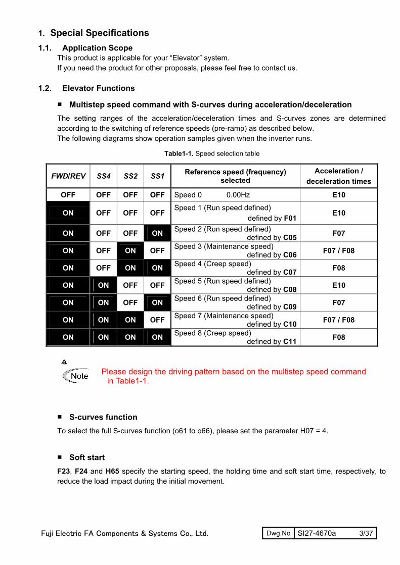
Multistep speed command with S-curves during acceleration/deceleration The setting ranges of the acceleration/deceleration times and S-curves zones are determined according to the switching of reference speeds (pre-ramp) as described below. The following diagrams show operation samples given when the inverter runs.
Table1-1. Speed selection table
FWD/REV SS4 SS2 SS1 Reference speed (frequency) selected
Acceleration / deceleration times
OFF OFF OFF OFF Speed 0 0.00Hz E10
ON OFF OFF OFF Speed 1 (Run speed defined)
defined by F01 E10
ON OFF OFF ON Speed 2 (Run speed defined) defined by C05 F07
ON OFF ON OFF Speed 3 (Maintenance speed) defined by C06 F07 / F08
ON OFF ON ON Speed 4 (Creep speed) defined by C07 F08
ON ON OFF OFF Speed 5 (Run speed defined) defined by C08 E10
ON ON OFF ON Speed 6 (Run speed defined) defined by C09 F07
ON ON ON OFF Speed 7 (Maintenance speed) defined by C10 F07 / F08
ON ON ON ON Speed 8 (Creep speed) defined by C11 F08
a
Please design the driving pattern based on the multistep speed commandin Table1-1.
S-curves function To select the full S-curves function (o61 to o66), please set the parameter H07 = 4.
Soft start F23, F24 and H65 specify the starting speed, the holding time and soft start time, respectively, to reduce the load impact during the initial movement.

Fuji Electric FA Components & Systems Co., Ltd. Dwg.No SI27-4670a 4/37
C05
: Hig
h sp
eed
C07
: Cre
ep S
peedSp
eed
FW
D
SS
1
SS
2
SW
52-2
(M
C)
0
F07:
Acc
eler
atio
n/de
cele
ratio
n tim
e 1
F08:
Acc
eler
atio
n/de
cele
ratio
n tim
e 2
o61:
S-c
urve
set
ting
1o62:
S-c
urve
set
ting
2o6
3: S
-cur
ve s
ettin
g 3
o64:
S-c
urve
set
ting
4
o65:
S-c
urve
set
ting
5
o66:
S-c
urve
set
ting
6
E10:
Acc
eler
atio
n/de
cele
ratio
n tim
e 3
BR
KS
(onl
y Mot
or1)
o75:
Sta
rtup
dela
y tim
e
H65
: Sof
t sta
rt tim
e
(Onl
y M
otor
1)
F24:
Hol
ding
tim
e
F39:
Hol
ding
tim
e
o76:
MC
OFF
del
ay ti
me
ON
ON
ON
ON
ON
F23:
Sta
rting
Spe
edJ6
9: B
rake
Rel
ease
Freq
uenc
y
Inve
rter m
ain
circ
uit
(out
put g
ate)
ON
F25:
Sto
p Sp
eed
J71:
Bra
ke A
pply
Fr
eque
ncy
J72:
Bra
ke A
pply
Tim
erJ7
0: B
rake
Rel
ease
Tim
er
Fig.1-1. Timing chart of Elevator driving

Fuji Electric FA Components & Systems Co., Ltd. Dwg.No SI27-4670a 5/37
1.3. Auto-resetting operation H04 and H05 specify the auto-resetting operation. Even if any protective function subject to auto-
resetting is activated, the inverter issues an alarm (for any faults) ALM. When it meets the following
requirements, the inverter will automatically resets the tripped state:
1) Run command off 2) Auto-resetting reset interval (H05) is elapsed 3) Auto resetting times (H04) not equal 0 4) Auto resetting times (internal counter) < H04 setting value
Table1-2. The recoverable alarm codes
Alarm status Alarm code on LED monitor Alarm status Alarm code on LED
monitor
Instantaneous overcurrent protection 0C1, 0C2, 0C3 Motor overheated 0H4
Overvoltage protection 0U1, 0U2, 0U3 Motor overloaded 0L1,OL2
Heat sink overheated 0H1 Inverter overloaded 0LU
Undervoltage detected LU - -
Number of auto-resetting times (H04) H04 specifies the number of auto-resetting times for automatically recover the tripped state. If the protective function is activated more than the specified auto-resetting times, the inverter issues an alarm (for any faults) and does not attempt to recover the tripped state.
- Data setting range: 0 (disable) 1 to 10 (times)
Reset interval (H05) H05 specifies the interval time to attempt performing auto-resetting the tripped state.
- Data setting range: 0.5 to 20.0 (s)
Run command
Alarm OutALM
Auto-resettingTRY
Auto-resetting reset Interval
(internalcounter)
Auto-resettingTimes
(internalcounter)
ON
ON
ON
H05
ON
ON
ON
Run ComandOFF is waited
for.
H04
ReferenceSpeed
Auto-resettingTimes clear
timer
24h
Fig.1-2. Operation timing scheme

Fuji Electric FA Components & Systems Co., Ltd. Dwg.No SI27-4670a 6/37
Auto-resetting operation condition 1) Auto-resetting times (H04) not equal 0 2) Auto-resetting times (internal counter) < H04 setting value
Auto-resetting times (internal counter) clear condition 1) Power OFF 2) When Auto resetting times parameter (H04) is changed 3) No alarm has occurred and 24 hours passed. 4) The alarm is reset manually.
Timing diagram of auto-resetting times (internal counter) cleared by manual reset When alarm reset is done while auto-resetting is operating, auto-resetting operation is interrupted and the auto-resetting times (internal counter) and auto-resetting times clear counter as well as auto-resetting is not operating.
Run command
Alarm outputALM
Auto-resettingTRY
Auto resettingReset interval
(internalcounter)
Auto-resettingtimes
(internalcounter)
ON
ON
ON
H05
ON
ON
ON
H04
Alarm resetRST ON ON
Reference speed
Auto-resettingtimes cleaer
timer
24h
Fig.1-3. Operation timing diagram of auto-resetting times

Fuji Electric FA Components & Systems Co., Ltd. Dwg.No SI27-4670a 7/37
Unrecoverable alarm statuses to be auto-reset occurs during auto-resetting operation When auto-resetting is operating and unrecoverable alarm statuses to be auto-reset occurs, auto-resetting operation is interrupted and manual reset is necessary.
Run command
Motor overheated
OH4
Auto-resettingTRY
Auto-resettingreset interval
(Internalcounter)
Auto-resettingtimes
(internalcounter)
ON
ON
ON
H05
H04
Operation errorEr6 ON
Alarm resetRST ON
Reference speed
Auto-resettingtimes clear
timer
24h
Fig.1-4. Operation timing diagram of unrecoverable alarm
Note: Even if the recoverable alarm status to be auto-reset occurs during auto-resetting operation, it doesn't have influence over auto-resetting operation.
Timing diagram for failed auto-resetting The alarm is reset when the run command is turned off after auto-resetting reset interval (H05) passes and when the alarm cannot be reset, the same operation is repeated. Auto-resetting doesn't operate when auto-resetting times (internal count) becomes more than auto-resetting times (H04).
Run command
Alarm outALM
Auto-resettingTRY
Auto-resettingreset interval
(Internalcounter)
Auto-resettingtimes
(Internalcounter)
ON
ON
ON
H05
H04
Can not bereset
Can not bereset
Can not bereset
Because of auto-resettingtimes is more than H04,
auto-resettingdoesn't work.
Referencespeed
Auto-resettingtimes clear timer
24hBecause of alarm is
occurred the counter stops
Fig.1-5. Operation timing diagram for failed auto-resetting
Note: Auto-resetting times clear timer After 24 hour, if alarm does not occur, auto-resetting time counter is cleared.
When all alarm is occurred, the auto-resetting time counter is cleared; auto-resetting time counter starts count up to 24
hours and the alarm is cleared by auto-resetting operation or manual reset.
Fuji Electric FA Components & Systems Co., Ltd. Dwg.No SI27-4670a 8/37
1.4. UPS operation
UPS operation
The UPS operation enables the inverter (during undervoltage situation) to move the elevator cage to the nearest floor. Therefore it rescues the passengers from the cage stopped halfway due to a main power failure. The UPS operation is only applicable to the motor 1.
Requirements for UPS operation
(1) The BATRY function (data = 63) must be assigned to any digital input terminal. (2) An AC voltage must be supplied from the UPS to the main circuit (R-T). The voltage level will
differ depending on the operation speed and load. (3) The BATRY function must be turned on.
Specifications
(1) The inverter can run the elevator starting from the voltage level specified in o80. (2) The RDY ("Inverter ready to run" signal) is forced to go OFF. (3) During the UPS operation, the inverter runs the elevator at the speed specified by C19. (4) In UPS operation, the acceleration/deceleration time are specified by E11. The S-curve during
acceleration/deceleration is disabled. (5) In UPS operation, the Overload Stop function becomes effective.
Please set J64, J65, J66 and J67. J64 sets the UPS detection level and below it, the inverter will work.
(6) The drive characteristics are adjusted with F23, F24, H65, and o81 (Torque boost gain with UPS operation).

Fuji Electric FA Components & Systems Co., Ltd. Dwg.No SI27-4670a 9/37
Block diagram
73
MC2
R,S,T
N(-)
UPS
Control circuit
MC1 M Edc +
Converter
Inverter
Power supply
Fig.1-6. Basic Wiring Diagram
Operation Profile
Main powerMC1
BATRYMC273X
UPS power supply
DC link bus voltage Edc
FWD
Output Frequency
Undervoltage level
C19: UPS Operation Speed
T1(0.5 s)
T2(0.1 s)
UPS operationallowable zone
ON
ON
ON
ON
ON
ON
ON
ON
S-curve acce./dece. disabled
E11 E110
o80: UPS Operation level
Input PowerJ64: Input power
Detection level0
REV ON
The inverter stopsautomatically.
BRKS ON
IOL ON
Fig.1-7. UPS operation Timing chart

Fuji Electric FA Components & Systems Co., Ltd. Dwg.No SI27-4670a 10/37
2. Standard Specifications 2.1. Standard Models 1) Three-phase 200Vseries (0.1 to 15kW)
Items Specifications Type
(FRNE1S-2LM) 0.1 0.2 0.4 0.75 1.5 2.2 3.7 5.5 7.5 11 15
Nominal applied motor *1) [kW] 0.1 0.2 0.4 0.75 1.5 2.2 3.7 5.5 7.5 11 15
Rated capacity *2 [kVA] 0.30 0.57 1.1 1.9 3.0 4.1 6.4 9.5 12 17 22
Rated voltage *3) [V] Three-phase 200 to 240V (With AVR)
Rated current [A] *4)
0.8 (0.7)
1.5 (1.4)
3.0 (2.5)
5.0 (4.2)
8.0 (7.0)
11 (10)
17 (16.5)
25 (23.5)
33 (31)
47
(44) 60
(57) Overload capability *9) 150% of rated current for 1min or 200% of rated current for 0.5s O
utpu
t rat
ings
Rated frequency 50, 60Hz Main power supply Three-phase 200 to 240V,50/60Hz Voltage/frequency variations Voltage: +10 to -15% (Voltage unbalance: 2% or less (*7)), Frequency: +5 to -5%
With DCR 0.57 0.93 1.6 3.0 5.7 8.3 14.0 21.1 28.8 42.2 57.6 Rated
current *8) [A] Without
DCR 1.1 1.8 3.1 5.3 9.5 13.2 22.2 31.5 42.7 60.7 80.0
Inpu
t rat
ings
Required power supply capacity *5) [kVA]
0.2 0.3 0.6 1.1 2.0 2.9 4.9 7.4 10 15 20
Braking torque*6) [%] 150 100 70 40 20
DC braking Starting frequency: 0.0 to 60.0Hz, Braking time: 0.0 to 30.0s, Braking level: 0 to 100%
Brak
ing
Transistor for braking resistor Built-in
Applicable safety standards UL508C, C22.2No.14, EN50178: 1997
Enclosure IP20 (IEC60529) / UL open type (UL50) Cooling method Natural cooling Fan cooling Mass [kg] 0.6 0.6 0.7 0.8 1.7 1.7 2.3 3.4 3.6 6.1 7.1
*1) Fuji's 4-pole standard motor
*2) Rated capacity is calculated by regarding the output rated voltage as 220V for three-phase 200V series.
*3) Output voltage cannot exceed the power supply voltage.
*4) The load shall be reduced so that the continuous operating current is the rated current in parenthesis or less if the carrier
frequency is set to 4kHz or above.
*5) Obtained when a DC REACTOR is used.
*6) Average braking torque when a motor of no load decelerates.(Varies with the efficiency of the motor.)
*7) 3(5.2.3))(IEC61800 67%[V] voltage average phase-Three[V] voltage Min.[V] voltage Max.
unbalance Voltage −×−
=
If this value is 2 to 3%, use an AC REACTOR.
*8) The currents are calculated on the condition that the inverters are connected to power supply of 500kVA, %X=5%.
*9) For 15kW, if ambient temperature exceeded 45 °C, the overload capability is obtained after continuous operation at 85% of
rated current.

Fuji Electric FA Components & Systems Co., Ltd. Dwg.No SI27-4670a 11/37
2) Three-phase 400V series(0.4 to 15kW)
Items Specifications Type
(FRNE1S-4LM) 0.4 0.75 1.5 2.2 3.7 5.5 7.5 11 15
Nominal applied motor *1) [kW] 0.4 0.75 1.5 2.2 3.7 5.5 7.5 11 15
Rated capacity *2 [kVA] 1.1 1.9 2.8 4.1 6.8 9.9 13 18 22
Rated voltage *3) [V] Three-phase 380 to 480V (With AVR)
Rated current [A] *4) 1.5 2.5 3.7 5.5 9.0 13 18 24 30
Overload capability *9) 150% of rated current for 1min or 200% of rated current for 0.5s O
utpu
t rat
ings
Rated frequency 50, 60Hz Main power supply Three-phase 380 to 480V,50/60Hz Voltage/frequency variations Voltage: +10 to -15% (Voltage unbalance: 2% or less (*7)), Frequency: +5 to -5%
With DCR 0.85 1.6 3.0 4.4 7.3 10.6 14.4 21.1 28.8 Rated
current *8) [A] Without
DCR 1.7 3.1 5.9 8.2 13.0 17.3 23.2 33.0 43.8
Inpu
t rat
ings
Required power supply capacity *5) [kVA]
0.6 1.1 2.0 2.9 4.9 7.4 10 15 20
Braking torque*6) [%] 100 70 40 20
DC braking Starting frequency: 0.0 to 60.0Hz, Braking time: 0.0 to 30.0s, Braking level: 0 to 100%
Brak
ing
Transistor for braking resistor Built-in
Applicable safety standards UL508C, C22.2No.14, EN50178: 1997
Enclosure IP20 (IEC60529) / UL open type (UL50) Cooling method Natural cooling Fan cooling Mass [kg] 1.1 1.2 1.7 1.7 2.3 3.4 3.6 6.1 7.1
*1) Fuji's 4-pole standard motor
*2) Rated capacity is calculated by regarding the output rated voltage as 220V for three-phase 200V series.
*3) Output voltage cannot exceed the power supply voltage.
*4) The load shall be reduced so that the continuous operating current is the rated current in parenthesis or less if the carrier
frequency is set to 4kHz or above.
*5) Obtained when a DC REACTOR is used.
*6) Average braking torque when a motor of no load decelerates.(Varies with the efficiency of the motor.)
*7) 3(5.2.3))(IEC61800 67%[V] voltage average phase-Three[V] voltage Min.[V] voltage Max.
unbalance Voltage −×−
=
If this value is 2 to 3%, use an AC REACTOR.
*8) The currents are calculated on the condition that the inverters are connected to power supply of 500kVA, %X=5%.
*9) For 15kW, if ambient temperature exceeded 45 °C, the overload capability is obtained after continuous operation at 85% of
rated current.
Fuji Electric FA Components & Systems Co., Ltd. Dwg.No SI27-4670a 12/37
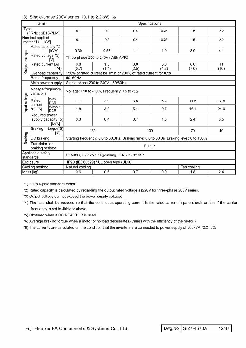
3) Single-phase 200V series(0.1 to 2.2kW)a Items Specifications
Type (FRNE1S-7LM) 0.1 0.2 0.4 0.75 1.5 2.2
Nominal applied motor *1) [kW] 0.1 0.2 0.4 0.75 1.5 2.2
Rated capacity *2 [kVA] 0.30 0.57 1.1 1.9 3.0 4.1
Rated voltage *3) [V] Three-phase 200 to 240V (With AVR)
Rated current [A] *4)
0.8 (0.7)
1.5 (1.4)
3.0 (2.5)
5.0 (4.2)
8.0 (7.0)
11 (10)
Overload capability 150% of rated current for 1min or 200% of rated current for 0.5s Out
put r
atin
gs
Rated frequency 50, 60Hz Main power supply Single-phase 200 to 240V,50/60Hz Voltage/frequency variations Voltage: +10 to -10%, Frequency: +5 to -5%
With DCR 1.1 2.0 3.5 6.4 11.6 17.5 Rated
current *8) [A] Without
DCR 1.8 3.3 5.4 9.7 16.4 24.0
Inpu
t rat
ings
Required power supply capacity *5) [kVA]
0.3 0.4 0.7 1.3 2.4 3.5
Braking torque*6) [%] 150 100 70 40
DC braking Starting frequency: 0.0 to 60.0Hz, Braking time: 0.0 to 30.0s, Braking level: 0 to 100%
Brak
ing
Transistor for braking resistor Built-in
Applicable safety standards UL508C, C22.2No.14(pending), EN50178:1997
Enclosure IP20 (IEC60529) / UL open type (UL50) Cooling method Natural cooling Fan cooling Mass [kg] 0.6 0.6 0.7 0.9 1.8 2.4
*1) Fuji's 4-pole standard motor
*2) Rated capacity is calculated by regarding the output rated voltage as220V for three-phase 200V series.
*3) Output voltage cannot exceed the power supply voltage.
*4) The load shall be reduced so that the continuous operating current is the rated current in parenthesis or less if the carrier
frequency is set to 4kHz or above.
*5) Obtained when a DC REACTOR is used.
*6) Average braking torque when a motor of no load decelerates.(Varies with the efficiency of the motor.)
*8) The currents are calculated on the condition that the inverters are connected to power supply of 500kVA, %X=5%.

Fuji Electric FA Components & Systems Co., Ltd. Dwg.No SI27-4670a 13/37
2.2. Models Available on Order (EMC filter built-in type) 1) Three-phase 200Vseries (0.1 to 15kW)a
Items Specifications Type
(FRNE1E-2LM) 0.1 0.2 0.4 0.75 1.5 2.2 3.7 5.5 7.5 11 15
Nominal applied motor *1) [kW] 0.1 0.2 0.4 0.75 1.5 2.2 3.7 5.5 7.5 11 15
Rated capacity *2 [kVA] 0.30 0.57 1.1 1.9 3.0 4.1 6.4 9.5 12 17 22
Rated voltage *3) [V] Three-phase 200 to 240V (With AVR)
Rated current [A] *4)
0.8 (0.7)
1.5 (1.4)
3.0 (2.5)
5.0 (4.2)
8.0 (7.0)
11 (10)
17 (16.5)
25 (23.5)
33 (31)
47
(44) 60
(57) Overload capability *9) 150% of rated current for 1min or 200% of rated current for 0.5s O
utpu
t rat
ings
Rated frequency 50, 60Hz Main power supply Three-phase 200 to 240V,50/60Hz Voltage/frequency variations Voltage: +10 to -15% (Voltage unbalance: 2% or less (*7)), Frequency: +5 to -5%
With DCR 0.57 0.93 1.6 3.0 5.7 8.3 14.0 21.1 28.8 42.2 57.6 Rated
current *8) [A] Without
DCR 1.1 1.8 3.1 5.3 9.5 13.2 22.2 31.5 42.7 60.7 80.0
Inpu
t rat
ings
Required power supply capacity *5) [kVA]
0.2 0.3 0.6 1.1 2.0 2.9 4.9 7.4 10 15 20
Braking torque*6) [%] 150 100 70 40 20
DC braking Starting frequency: 0.0 to 60.0Hz, Braking time: 0.0 to 30.0s, Braking level: 0 to 100%
Brak
ing
Transistor for braking resistor Built-in
Applicable safety standards UL508C, C22.2No.14, EN50178: 1997
Enclosure IP20 (IEC60529) / UL open type (UL50) Cooling method Natural cooling Fan cooling
Emission Class 1A (EN55011:1998/A1:1999) 2nd Env. (EN61800-3:1996+A11:2000)
EMC standard compliance Immunity 2nd Env. (EN61800-3:1996/A11:2000) Mass [kg] 0.7 0.7 0.8 0.9 2.4 2.4 2.9 5.1 5.3 10.3 11.3
*1) Fuji's 4-pole standard motor
*2) Rated capacity is calculated by regarding the output rated voltage as220V for three-phase 200V series.
*3) Output voltage cannot exceed the power supply voltage.
*4) The load shall be reduced so that the continuous operating current is the rated current in parenthesis or less if the carrier
frequency is set to 4kHz or above.
*5) Obtained when a DC REACTOR is used.
*6) Average braking torque when a motor of no load decelerates.(Varies with the efficiency of the motor.)
*7) 3(5.2.3))(IEC61800 67%[V] voltage average phase-Three[V] voltage Min.[V] voltage Max.
unbalance Voltage −×−
=
If this value is 2 to 3%, use an AC REACTOR.
*8) The currents are calculated on the condition that the inverters are connected to power supply of 500kVA, %X=5%.
*9) For 15kW, if ambient temperature exceeded 45 °C, the overload capability is obtained after continuous operation at 85% of
rated current.

Fuji Electric FA Components & Systems Co., Ltd. Dwg.No SI27-4670a 14/37
2) Three-phase 400V series(0.4 to 15kW)a
Items Specifications Type
(FRNE1E-4LM) 0.4 0.75 1.5 2.2 3.7 5.5 7.5 11 15
Nominal applied motor *1) [kW] 0.4 0.75 1.5 2.2 3.7 5.5 7.5 11 15
Rated capacity *2 [kVA] 1.1 1.9 2.8 4.1 6.8 9.9 13 18 22
Rated voltage *3) [V] Three-phase 380 to 480V (With AVR)
Rated current [A] *4) 1.5 2.5 3.7 5.5 9.0 13 18 24 30
Overload capability *9) 150% of rated current for 1min or 200% of rated current for 0.5s O
utpu
t rat
ings
Rated frequency 50, 60Hz Main power supply Three-phase 380 to 480V,50/60Hz Voltage/frequency variations Voltage: +10 to -15% (Voltage unbalance: 2% or less (*7)), Frequency: +5 to -5%
With DCR 0.85 1.6 3.0 4.4 7.3 10.6 14.4 21.1 28.8 Rated
current *8) [A] Without
DCR 1.7 3.1 5.9 8.2 13.0 17.3 23.2 33.0 43.8
Inpu
t rat
ings
Required power supply capacity *5) [kVA]
0.6 1.1 2.0 2.9 4.9 7.4 10 15 20
Braking torque*6) [%] 100 70 40 20
DC braking Starting frequency: 0.0 to 60.0Hz, Braking time: 0.0 to 30.0s, Braking level: 0 to 100%
Brak
ing
Transistor for braking resistor Built-in
Applicable safety standards UL508C, C22.2No.14, EN50178: 1997
Enclosure IP20 (IEC60529) / UL open type (UL50) Cooling method Natural cooling Fan cooling
Emission Class 1A (EN55011:1998/A1:1999) 2nd Env. (EN61800-3:1996+A11:2000) EMC standard compliance Immunity 2nd Env. (EN61800-3:1996/A11:2000)
Mass [kg] 1.5 1.6 2.5 2.5 3.0 4.8 5.0 8.1 9.1
*1) Fuji's 4-pole standard motor
*2) Rated capacity is calculated by regarding the output rated voltage as220V for three-phase 200V series.
*3) Output voltage cannot exceed the power supply voltage.
*4) The load shall be reduced so that the continuous operating current is the rated current in parenthesis or less if the carrier
frequency is set to 4kHz or above.
*5) Obtained when a DC REACTOR is used.
*6) Average braking torque when a motor of no load decelerates.(Varies with the efficiency of the motor.)
*7) 3(5.2.3))(IEC61800 67%[V] voltage average phase-Three[V] voltage Min.[V] voltage Max.
unbalance Voltage −×−
=
If this value is 2 to 3%, use an AC REACTOR.
*8) The currents are calculated on the condition that the inverters are connected to power supply of 500kVA, %X=5%.
*9) For 15kW, if ambient temperature exceeded 45 °C, the overload capability is obtained after continuous operation at 85% of rated current.

Fuji Electric FA Components & Systems Co., Ltd. Dwg.No SI27-4670a 15/37
3) Single-phase 200V series(0.1 to 2.2kW)a Items Specifications
Type (FRNE1E-7LM) 0.1 0.2 0.4 0.75 1.5 2.2
Nominal applied motor *1) [kW] 0.1 0.2 0.4 0.75 1.5 2.2
Rated capacity *2 [kVA] 0.30 0.57 1.1 1.9 3.0 4.1
Rated voltage *3) [V] Three-phase 200 to 240V (With AVR)
Rated current [A] *4)
0.8 (0.7)
1.5 (1.4)
3.0 (2.5)
5.0 (4.2)
8.0 (7.0)
11 (10)
Overload capability 150% of rated current for 1min or 200% of rated current for 0.5s Out
put r
atin
gs
Rated frequency 50, 60Hz Main power supply Single-phase 200 to 240V,50/60Hz Voltage/frequency variations Voltage: +10 to -10%, Frequency: +5 to -5%
With DCR 1.1 2.0 3.5 6.4 11.6 17.5 Rated
current *8) [A] Without
DCR 1.8 3.3 5.4 9.7 16.4 24.0
Inpu
t rat
ings
Required power supply capacity *5) [kVA]
0.3 0.4 0.7 1.3 2.4 3.5
Braking torque*6) [%] 150 100 70 40
DC braking Starting frequency: 0.0 to 60.0Hz, Braking time: 0.0 to 30.0s, Braking level: 0 to 100%
Brak
ing
Transistor for braking resistor Built-in
Applicable safety standards UL508C, C22.2No.14, EN50178:1997
Enclosure IP20 (IEC60529) / UL open type (UL50) Cooling method Natural cooling Fan cooling
Emission Class 1A (EN55011:1998/A1:1999) EMC standard compliance Immunity 2nd Env. (EN61800-3:1996/A11:2000)
Mass [kg] 0.7 0.7 0.8 1.3 2.5 3.0
*1) Fuji's 4-pole standard motor
*2) Rated capacity is calculated by regarding the output rated voltage as220V for three-phase 200V series.
*3) Output voltage cannot exceed the power supply voltage.
*4) The load shall be reduced so that the continuous operating current is the rated current in parenthesis or less if the carrier
frequency is set to 4kHz or above.
*5) Obtained when a DC REACTOR is used.
*6) Average braking torque when a motor of no load decelerates.(Varies with the efficiency of the motor.)
*8) The currents are calculated on the condition that the inverters are connected to power supply of 500kVA, %X=5%
Fuji Electric FA Components & Systems Co., Ltd. Dwg.No SI27-4670a 16/37
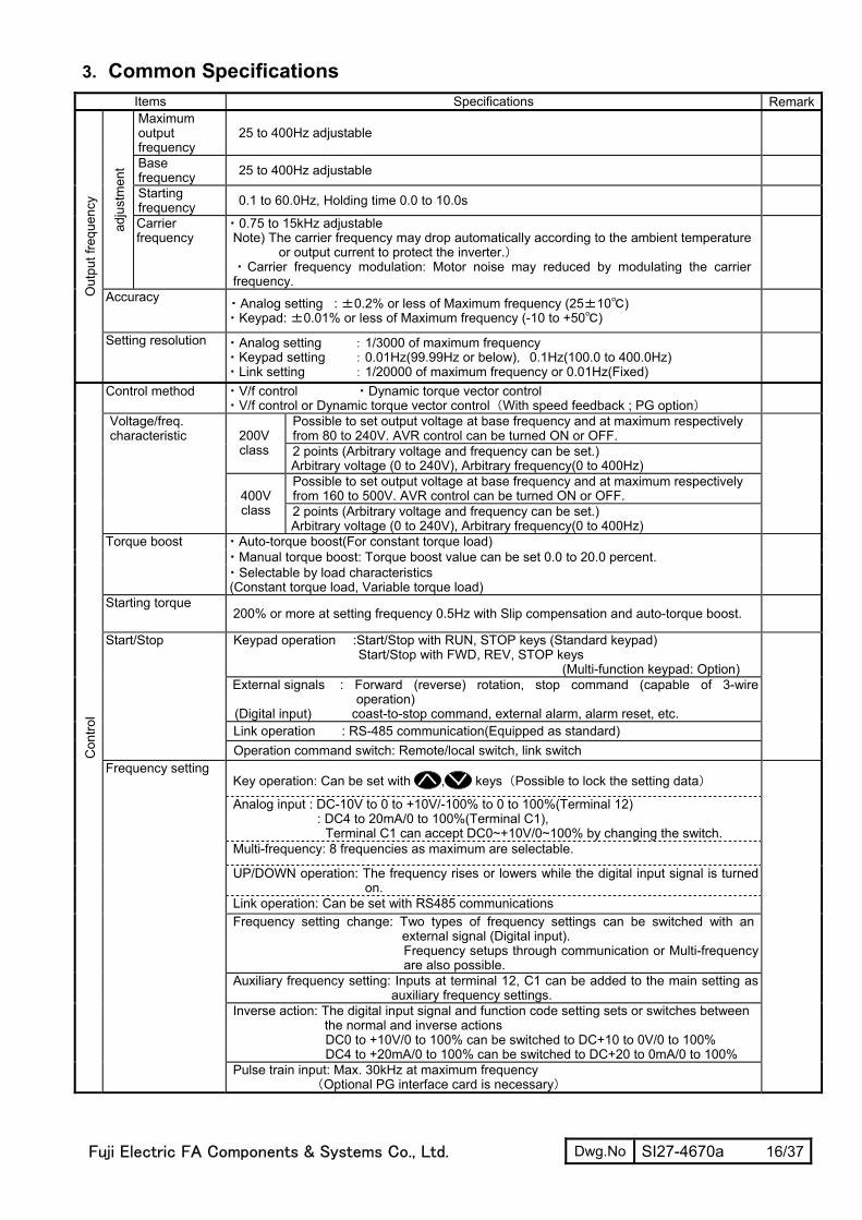
3. Common Specifications Items Specifications RemarkMaximum output frequency
25 to 400Hz adjustable
Base frequency 25 to 400Hz adjustable
Starting frequency 0.1 to 60.0Hz, Holding time 0.0 to 10.0s
adju
stm
ent
Carrier frequency
・0.75 to 15kHz adjustable Note) The carrier frequency may drop automatically according to the ambient temperature
or output current to protect the inverter.) ・Carrier frequency modulation: Motor noise may reduced by modulating the carrier frequency.
Accuracy ・Analog setting : ±0.2% or less of Maximum frequency (25±10) ・Keypad: ±0.01% or less of Maximum frequency (-10 to +50)
Out
put f
requ
ency
Setting resolution ・Analog setting :1/3000 of maximum frequency ・Keypad setting :0.01Hz(99.99Hz or below),0.1Hz(100.0 to 400.0Hz) ・Link setting :1/20000 of maximum frequency or 0.01Hz(Fixed)
Control method ・V/f control ・Dynamic torque vector control ・V/f control or Dynamic torque vector control(With speed feedback ; PG option)
Possible to set output voltage at base frequency and at maximum respectively from 80 to 240V. AVR control can be turned ON or OFF. 200V
class 2 points (Arbitrary voltage and frequency can be set.) Arbitrary voltage (0 to 240V), Arbitrary frequency(0 to 400Hz) Possible to set output voltage at base frequency and at maximum respectively from 160 to 500V. AVR control can be turned ON or OFF.
Voltage/freq. characteristic
400V class 2 points (Arbitrary voltage and frequency can be set.)
Arbitrary voltage (0 to 240V), Arbitrary frequency(0 to 400Hz)
・Auto-torque boost(For constant torque load) ・Manual torque boost: Torque boost value can be set 0.0 to 20.0 percent.
Torque boost
・Selectable by load characteristics (Constant torque load, Variable torque load)
Starting torque 200% or more at setting frequency 0.5Hz with Slip compensation and auto-torque boost.
Keypad operation :Start/Stop with RUN, STOP keys (Standard keypad) Start/Stop with FWD, REV, STOP keys
(Multi-function keypad: Option) External signals : Forward (reverse) rotation, stop command (capable of 3-wire
operation) (Digital input) coast-to-stop command, external alarm, alarm reset, etc. Link operation : RS-485 communication(Equipped as standard)
Start/Stop
Operation command switch: Remote/local switch, link switch
Key operation: Can be set with , keys(Possible to lock the setting data)
Analog input : DC-10V to 0 to +10V/-100% to 0 to 100%(Terminal 12) : DC4 to 20mA/0 to 100%(Terminal C1),
Terminal C1 can accept DC0~+10V/0~100% by changing the switch. Multi-frequency: 8 frequencies as maximum are selectable.
UP/DOWN operation: The frequency rises or lowers while the digital input signal is turned on.
Link operation: Can be set with RS485 communications Frequency setting change: Two types of frequency settings can be switched with an
external signal (Digital input). Frequency setups through communication or Multi-frequency are also possible.
Auxiliary frequency setting: Inputs at terminal 12, C1 can be added to the main setting as auxiliary frequency settings.
Inverse action: The digital input signal and function code setting sets or switches between the normal and inverse actions DC0 to +10V/0 to 100% can be switched to DC+10 to 0V/0 to 100% DC4 to +20mA/0 to 100% can be switched to DC+20 to 0mA/0 to 100%
Con
trol
Frequency setting
Pulse train input: Max. 30kHz at maximum frequency (Optional PG interface card is necessary)
Fuji Electric FA Components & Systems Co., Ltd. Dwg.No SI27-4670a 17/37
Items Specifications Remark
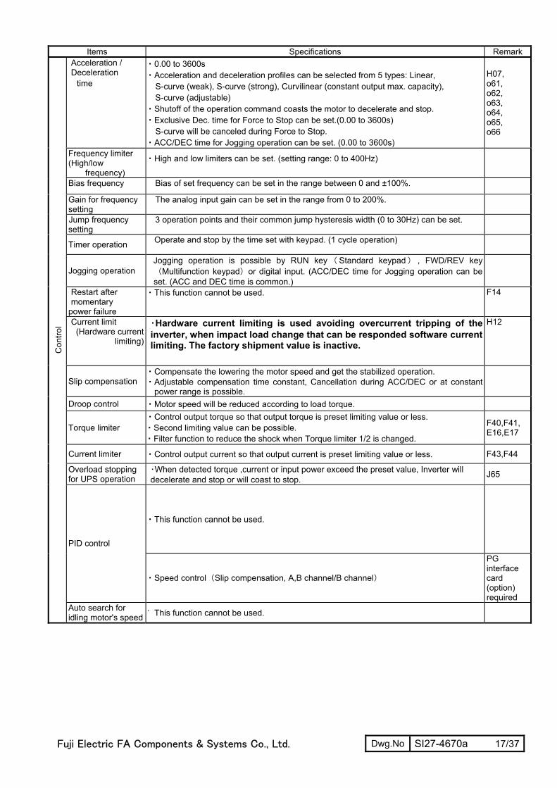
Acceleration / Deceleration
time
・0.00 to 3600s ・Acceleration and deceleration profiles can be selected from 5 types: Linear, S-curve (weak), S-curve (strong), Curvilinear (constant output max. capacity), S-curve (adjustable)
・Shutoff of the operation command coasts the motor to decelerate and stop. ・Exclusive Dec. time for Force to Stop can be set.(0.00 to 3600s) S-curve will be canceled during Force to Stop. ・ACC/DEC time for Jogging operation can be set. (0.00 to 3600s)
H07, o61, o62, o63, o64, o65, o66
Frequency limiter (High/low
frequency)
・High and low limiters can be set. (setting range: 0 to 400Hz)
Bias frequency Bias of set frequency can be set in the range between 0 and ±100%. Gain for frequency setting
The analog input gain can be set in the range from 0 to 200%.
Jump frequency setting
3 operation points and their common jump hysteresis width (0 to 30Hz) can be set.
Timer operation Operate and stop by the time set with keypad. (1 cycle operation)
Jogging operation Jogging operation is possible by RUN key(Standard keypad) , FWD/REV key(Multifunction keypad)or digital input. (ACC/DEC time for Jogging operation can be set. (ACC and DEC time is common.)
Restart after momentary
power failure
・This function cannot be used.
F14
Current limit (Hardware current
limiting)
・Hardware current limiting is used avoiding overcurrent tripping of the inverter, when impact load change that can be responded software current limiting. The factory shipment value is inactive.
H12
Slip compensation ・Compensate the lowering the motor speed and get the stabilized operation. ・Adjustable compensation time constant, Cancellation during ACC/DEC or at constant
power range is possible.
Droop control ・Motor speed will be reduced according to load torque.
Torque limiter ・Control output torque so that output torque is preset limiting value or less. ・Second limiting value can be possible. ・Filter function to reduce the shock when Torque limiter 1/2 is changed.
F40,F41, E16,E17
Current limiter ・Control output current so that output current is preset limiting value or less. F43,F44
Overload stopping for UPS operation
・When detected torque ,current or input power exceed the preset value, Inverter will decelerate and stop or will coast to stop. J65
・This function cannot be used.
PID control
・Speed control(Slip compensation, A,B channel/B channel)
PG interface card (option) required
Con
trol
Auto search for idling motor's speed
・ This function cannot be used.

Fuji Electric FA Components & Systems Co., Ltd. Dwg.No SI27-4670a 18/37
Items Specifications Remark
Automatic Deceleration
・ This function cannot be used.
Deceleration Characteristics
Make the motor loss increase during deceleration so as to reduce the regenerative energy from motor and avoid Overvoltage trip.
Auto-energy saving operation
・ This function cannot be used.
Active drive The output frequency is automatically reduced to suppress the overload protection trip of the inverter caused by an increase in the IGBT junction temperature or the ambient temperature, motor load or similar.
Auto-tuning The motor parameters are automatically tuned. Cooling fan ON/OFF control
Detects inverter internal temperature and stops cooling fan when the temperature is low. An external output is issued in a transistor output signal.
Second motor parameters
・One inverter can drive the another motor changing from a motor. The function data set for second motor are base frequency, rated current, torque boost, Electronic overload protection for motor, slip compensation, etc…
・Second motor parameters can be preset in the inverter. Auto-tuning is possible.
Universal DI ・An arbitrary digital input signal is transmitted to the host controller. Universal AO ・An arbitrary data from host controller is output to terminal FM.
Speed control Motor speed is detected using a pulse encoder and control the motor speed. A PG interface card (option) is required.
Position control ・ This function cannot be used.
Con
trol
Limiting the direction of the motor rotation
Reverse rotation inhibited,/Forward rotation inhibited selectable
Running /stopping
• Speed monitor, output current [A], output voltage [V], torque calculation value, input power [kW], load factor, motor output, Time [s] for timer operation
・Select the speed monitor to be displayed among the following: Set frequency, Output frequency1 [Hz](Before slip compensation), Output frequency2 [Hz] (After slip compensation), motor speed setting [r/min], motor speed [r/min.], load shaft speed setting [r/min.], load shaft speed [r/min.], Line speed setting [m/min], Line speed [r/min], Constant Feeding Rate Time setting [min], Constant Feeding Rate Time [min]
Life early warning
The life early warning of the main circuit capacitors, capacitors on the PC boards and the cooling fan can be displayed.
Cumulative run hours
The cumulative motor running hours, cumulative inverter running hours and cumulative watt-hours can be displayed.
I/O checking Indicate the status of the Di, Do on the control circuit.
Indi
catio
n
Energy saving monitor
Input power, Input power×coefficient are indicated.
Fuji Electric FA Components & Systems Co., Ltd. Dwg.No SI27-4670a 19/37
Items Specifications Remark
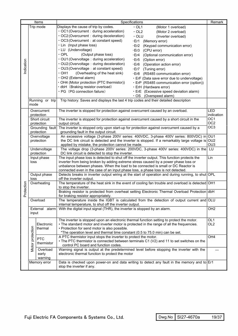
Trip mode Displays the cause of trip by codes. ・OC1 (Overcurrent:during acceleration) ・OC2 (Overcurrent:during deceleration) ・OC3 (Overcurrent:at constant speed) ・Lin (Input phase loss) ・LU (Undervoltage) ・OPL (Output phase loss) ・OU1 (Overvoltage:during acceleration) ・OU2 (Overvoltage:during deceleration) ・OU3 (Overvoltage:at constant speed) ・OH1 (Overheating of the heat sink) ・OH2 (External alarm) ・OH4 (Motor protection (PTC thermistor)) ・dbH(Braking resistor overload) ・PG(PG connection failure)
・OL1 (Motor 1 overload) ・OL2 (Motor 2 overload) ・OLU (Inverter overload) ・Er1 (Memory error) ・Er2 (Keypad communication error) ・Er3 (CPU error) ・Er4 (Optional communication error) ・Er5 (Option error) ・Er6 (Operation action error) ・Er7 (Tuning error) ・Er8 (RS485 communication error) ・ErF (Data save error due to undervoltage) ・ErP (RS485 communication error (option))・ErH (Hardware error) ・ErE (Excessive speed deviation alarm) ・OS (Overspeed alarm)
In
dica
tion
Running or trip mode
Trip history: Saves and displays the last 4 trip codes and their detailed description
Overcurrent protection
The inverter is stopped for protection against overcurrent caused by an overload.
Short circuit protection
The inverter is stopped for protection against overcurrent caused by a short circuit in the output circuit.
Grounding fault protection
The inverter is stopped only upon start-up for protection against overcurrent caused by a grounding fault in the output circuit.
LED indicationOC1 OC2 OC3
Overvoltage protection
An excessive voltage (3-phase 200V series: 400VDC, 3-phase 400V series: 800VDC) in the DC link circuit is detected and the inverter is stopped. If a remarkably large voltage is applied by mistake, the protection cannot be made.
OU1 OU2 OU3
Undervoltage protection
The voltage drop (3-phase 200V series: 200VDC, 3-phase 400V series: 400VDC) in the DC link circuit is detected to stop the inverter.
LU
Input phase loss
The input phase loss is detected to shut off the inverter output. This function protects the inverter from being broken by adding extreme stress caused by a power phase loss or unbalance between phases. When the load to be connected is small or DC Reactor is connected even in the case of an input phase loss, a phase loss is not detected.
Lin
Output phase loss
Detects breaks in inverter output wiring at the start of operation and during running, to shut off the inverter output.
OPL
The temperature of the heat sink in the event of cooling fan trouble and overload is detected to stop the inverter.
OH1
Overheating
Braking resistor is protected from overheat setting Electronic Thermal Overload Protection for braking resistor appropriately.
dbH
Overload The temperature inside the IGBT is calculated from the detection of output current and internal temperature, to shut off the inverter output.
OLU
External alarm input
With the digital input signal (THR), the inverter is stopped by an alarm. OH2
Electronic thermal
The inverter is stopped upon an electronic thermal function setting to protect the motor. • The standard motor and inverter motor is protected in the range of all the frequencies. • Protection for send motor is also possible.
*The operation level and thermal time constant (0.5 to 75.0 min) can be set.
OL1 OL2
PTC thermistor
A PTC thermistor input stops the inverter to protect the motor. • The PTC thermistor is connected between terminals C1 (V2) and 11 to set switches on the
control PC board and function codes.
OH4
Mot
or p
rote
ctio
n
Overload early warning
Warning signal is output at the predetermined level before stopping the inverter with the electronic thermal function to protect the motor
―
Pro
tect
ion
Memory error Data is checked upon power-on and data writing to detect any fault in the memory and to stop the inverter if any.
Er1
Fuji Electric FA Components & Systems Co., Ltd. Dwg.No SI27-4670a 20/37
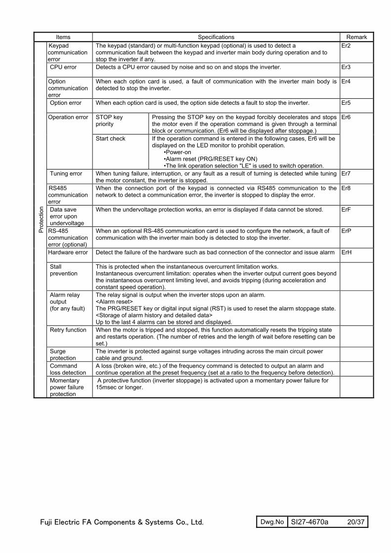
Items Specifications Remark
Keypad communication error
The keypad (standard) or multi-function keypad (optional) is used to detect a communication fault between the keypad and inverter main body during operation and to stop the inverter if any.
Er2
CPU error Detects a CPU error caused by noise and so on and stops the inverter. Er3
Option communication error
When each option card is used, a fault of communication with the inverter main body is detected to stop the inverter.
Er4
Option error When each option card is used, the option side detects a fault to stop the inverter. Er5
STOP key priority
Pressing the STOP key on the keypad forcibly decelerates and stops the motor even if the operation command is given through a terminal block or communication. (Er6 will be displayed after stoppage.)
Operation error
Start check If the operation command is entered in the following cases, Er6 will be displayed on the LED monitor to prohibit operation.
•Power-on •Alarm reset (PRG/RESET key ON) •The link operation selection "LE" is used to switch operation.
Er6
Tuning error When tuning failure, interruption, or any fault as a result of turning is detected while tuning the motor constant, the inverter is stopped.
Er7
RS485 communication error
When the connection port of the keypad is connected via RS485 communication to the network to detect a communication error, the inverter is stopped to display the error.
Er8
Data save error upon undervoltage
When the undervoltage protection works, an error is displayed if data cannot be stored. ErF
RS-485 communication error (optional)
When an optional RS-485 communication card is used to configure the network, a fault of communication with the inverter main body is detected to stop the inverter.
ErP
Hardware error Detect the failure of the hardware such as bad connection of the connector and issue alarm ErH
Stall prevention
This is protected when the instantaneous overcurrent limitation works. Instantaneous overcurrent limitation: operates when the inverter output current goes beyond the instantaneous overcurrent limiting level, and avoids tripping (during acceleration and constant speed operation).
Alarm relay output (for any fault)
The relay signal is output when the inverter stops upon an alarm. <Alarm reset> The PRG/RESET key or digital input signal (RST) is used to reset the alarm stoppage state.<Storage of alarm history and detailed data> Up to the last 4 alarms can be stored and displayed.
Retry function When the motor is tripped and stopped, this function automatically resets the tripping state and restarts operation. (The number of retries and the length of wait before resetting can be set.)
Surge protection
The inverter is protected against surge voltages intruding across the main circuit power cable and ground.
Command loss detection
A loss (broken wire, etc.) of the frequency command is detected to output an alarm and continue operation at the preset frequency (set at a ratio to the frequency before detection).
Pro
tect
ion
Momentary power failure protection
A protective function (inverter stoppage) is activated upon a momentary power failure for 15msec or longer.
Fuji Electric FA Components & Systems Co., Ltd. Dwg.No SI27-4670a 21/37
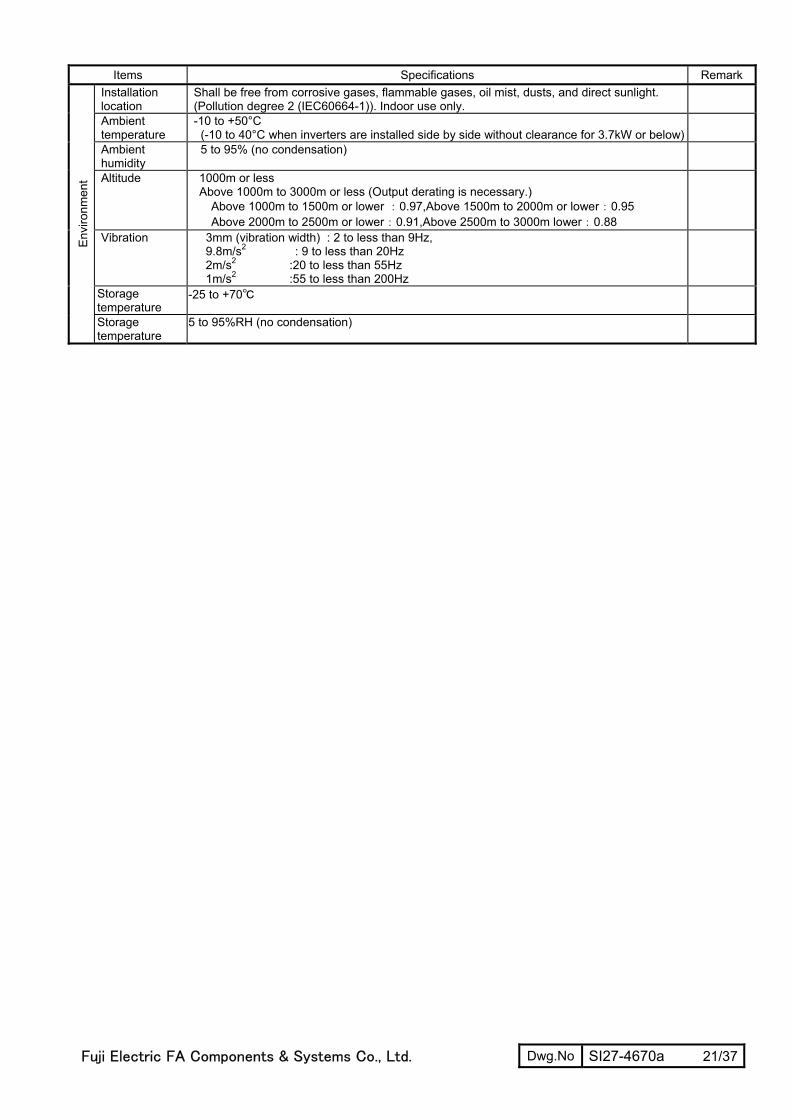
Items Specifications Remark
Installation location
Shall be free from corrosive gases, flammable gases, oil mist, dusts, and direct sunlight. (Pollution degree 2 (IEC60664-1)). Indoor use only.
Ambient temperature
-10 to +50°C (-10 to 40°C when inverters are installed side by side without clearance for 3.7kW or below)
Ambient humidity
5 to 95% (no condensation)
Altitude 1000m or less Above 1000m to 3000m or less (Output derating is necessary.)
Above 1000m to 1500m or lower :0.97,Above 1500m to 2000m or lower:0.95 Above 2000m to 2500m or lower:0.91,Above 2500m to 3000m lower:0.88
Vibration 3mm (vibration width) : 2 to less than 9Hz, 9.8m/s2 : 9 to less than 20Hz 2m/s2 :20 to less than 55Hz 1m/s2 :55 to less than 200Hz
Storage temperature
-25 to +70
Env
ironm
ent
Storage temperature
5 to 95%RH (no condensation)
Fuji Electric FA Components & Systems Co., Ltd. Dwg.No SI27-4670a 22/37
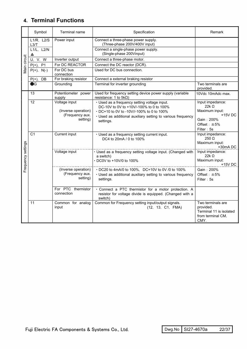
4. Terminal Functions
Symbol Terminal name Specification Remark
L1/R,L2/S L3/T
Power input Connect a three-phase power supply. (Three-phase 200V/400V input)
L1/L,L2/N a
Connect a single-phase power supply. (Single-phase 200Vinput)
U,V,W Inverter output Connect a three-phase motor. P(+),P1 For DC REACTOR Connect the DC reactor (DCR). P(+),N(-) For DC bus
connection Used for DC bus connection.
P(+),DB For braking resistor Connect a external braking resistor
Mai
n ci
rcui
t
G Grounding Terminal for inverter grounding Two terminals are provided.
13 Potentiometer power supply
Used for frequency setting device power supply (variable resistance: 1 to 5kΩ)
10Vdc 10mAdc max.
12 Voltage input
(Inverse operation) (Frequency aux.
setting)
・Used as a frequency setting voltage input. DC-10V to 0V to +10V/-100% to 0 to 100%
・DC+10 to 0V to -10V//-100% to 0 to 100% ・Used as additional auxiliary setting to various frequency
settings.
Input impedance: 22k Ω
Maximum input: +15V DC
Gain:200% Offset:±5% Filter:5s
Current input ・Used as a frequency setting current input. DC4 to 20mA / 0 to 100%
Input impedance: 250 Ω
Maximum input: +30mA DC
Voltage input
・Used as a frequency setting voltage input. (Changed with a switch)
・DC0V to +10V/0 to 100%
Input impedance: 22k Ω
Maximum input: +15V DC
(Inverse operation) (Frequency aux.
setting)
・DC20 to 4mA/0 to 100%,DC+10V to 0V /0 to 100% ・Used as additional auxiliary setting to various frequency
settings.
Gain:200% Offset:±5% Filter:5s
C1
For PTC thermistor connection
・Connect a PTC thermistor for a motor protection. A resistor for voltage divide is equipped. (Changed with a switch)
Freq
uenc
y se
tting
s
11 Common for analog input
Common for Frequency setting input/output signals. (12,13,C1,FMA)
Two terminals are provided. Terminal 11 is isolated from terminal CM,CMY.

Fuji Electric FA Components & Systems Co., Ltd. Dwg.No SI27-4670a 23/37
Symbol Terminal name Specification Remark X1 Digital input 1 X2 Digital input 2 X3 Digital input 3 X4 Digital input 4 X5 Digital input 5 FWD Forward operation
command REV Reverse operation
command
The following functions can be set at terminals X1 to X5, FWD and REV for signal input. <Common function> • Sink and source are changeable using the built-in sliding switch. • Input logic can be changed between short-circuit of terminals X1 and CM and open circuits of them. The same setting is possible between CM and any of the terminals among X2, X3, X4, X5, FWD, and REV.
ON state Source current:
2.5 to 5mA Voltage level: 2V OFF state Allowable leakage current: Smaller than 0.5mA Voltage: 22 to 27V
(FWD) Forward operation command
The motor runs in the forward direction upon ON across (FWD) and CM. The motor decelerates and stops upon OFF.
(REV) Reverse operation command
The motor runs in the reverse direction upon ON across (REV) and CM. The motor decelerates and stops upon OFF.
This function can be set only for the terminals FWD and REV. Only an active ON signal is acceptable.
(SS1) (SS2) (SS4)
Select Multi-frequency
8 frequencies can be selected with ON/OFF signals at (SS1) to (SS4).
(HLD) 3-wire operation stop command
Used for 3-wire operation. ON across (HLD) and CM: The inverter self-holds FWD or REV signal. OFF across (HLD) and CM: The inverter releases self-holding.
(BX) Coast to a stop The inverter output is shut off immediately and the motor coasts to a stop when (BX) is ON.
(RST) Reset alarm Faults are reset when (RST) is ON. 0.1s or more signal required.
(THR) External alarm trip The inverter output is shut off immediately and the motor coasts-to-stop when (THR) is OFF.
(Hz2/Hz1) Select frequency command 2/1
Frequency setting 2 is selected when (Hz2/Hz1) s ON.
(M2/M1) Motor2/Motor1 Motor 1 is effective when (M2/M1) is OFF and Motor 2 is effective when (M2/M1) is ON.
(DCBRK) Enable DC braking DC braking is enabled when (DCBRK) is ON. (TL2/TL1) Select torque limiter
level Torque limiter level 1 is selected when (TL2/TL1) is OFF and Torque limiter level 2 is selected when (TL2/TL1) is ON.
(UP) UP command The output frequency increases while (UP) is ON. (DOWN) DOWN command The output frequency decreases while (DOWN) is ON. (WE-KP) Enable data change
with keypad Enable data change with keypad when (WE-KP) is ON.
(IVS) Switch normal/inverse operation
The frequency setting switches between normal and inverse actions according to (IVS) ON/OFF status.
(LE) Enable communication link via RS-485
Enable communication link via RS-485 when (LE) is ON.
(U-DI) Universal DI An arbitrary digital input signal is transmitted to the host controller.
(STOP) Force to stop Inverter decelerates and stops with a deceleration time for force to stop when (STOP) is ON.
(JOG) Ready for jogging Operation mode is changed to Jogging mode and frequency, ACC/DEC time are changed to those for Jogging operation when (JOG) is ON.
(BATRY) UPS operation The UPS operation is effective when (BATRY) is ON PLC PLC terminal Connect to PLC output signal power supply. Common for
24V power. +24V (22 to 27V) 50mA max.
Dig
ital i
nput
s
CM Common for digital inputs
Common for digital inputs CM is isolated from 11, CMY. Two terminals are provided.
Fuji Electric FA Components & Systems Co., Ltd. Dwg.No SI27-4670a 24/37
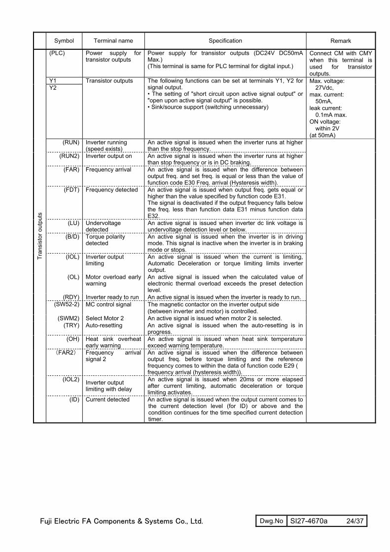
Symbol Terminal name Specification Remark
(PLC) Power supply for transistor outputs
Power supply for transistor outputs (DC24V DC50mA Max.) (This terminal is same for PLC terminal for digital input.)
Connect CM with CMY when this terminal is used for transistor outputs.
Y1 Y2
Transistor outputs The following functions can be set at terminals Y1, Y2 for signal output. • The setting of "short circuit upon active signal output" or "open upon active signal output" is possible. • Sink/source support (switching unnecessary)
Max. voltage: 27Vdc,
max. current: 50mA,
leak current: 0.1mA max.
ON voltage: within 2V
(at 50mA) (RUN) Inverter running
(speed exists) An active signal is issued when the inverter runs at higher than the stop frequency.
(RUN2) Inverter output on An active signal is issued when the inverter runs at higher than stop frequency or is in DC braking.
(FAR) Frequency arrival An active signal is issued when the difference between output freq. and set freq. is equal or less than the value of function code E30 Freq. arrival (Hysteresis width).
(FDT) Frequency detected An active signal is issued when output freq. gets equal or higher than the value specified by function code E31. The signal is deactivated if the output frequency falls below the freq. less than function data E31 minus function data E32.
(LU) Undervoltage detected
An active signal is issued when inverter dc link voltage is undervoltage detection level or below.
(B/D) Torque polarity detected
An active signal is issued when the inverter is in driving mode. This signal is inactive when the inverter is in braking mode or stops.
(IOL) Inverter output limiting
An active signal is issued when the current is limiting, Automatic Deceleration or torque limiting limits inverter output.
(OL) Motor overload early warning
An active signal is issued when the calculated value of electronic thermal overload exceeds the preset detection level.
(RDY) Inverter ready to run An active signal is issued when the inverter is ready to run. (SW52-2) MC control signal The magnetic contactor on the inverter output side
(between inverter and motor) is controlled. (SWM2) Select Motor 2 An active signal is issued when motor 2 is selected.
(TRY) Auto-resetting An active signal is issued when the auto-resetting is in progress.
(OH) Heat sink overheat early warning
An active signal is issued when heat sink temperature exceed warning temperature.
(FAR2) Frequency arrival signal 2
An active signal is issued when the difference between output freq. before torque limiting and the reference frequency comes to within the data of function code E29 ( frequency arrival (hysteresis width)).
(IOL2) Inverter output limiting with delay
An active signal is issued when 20ms or more elapsed after current limiting, automatic deceleration or torque limiting activates.
Tran
sist
or o
utpu
ts
(ID) Current detected An active signal is issued when the output current comes to the current detection level (for ID) or above and the condition continues for the time specified current detection timer.
Fuji Electric FA Components & Systems Co., Ltd. Dwg.No SI27-4670a 25/37
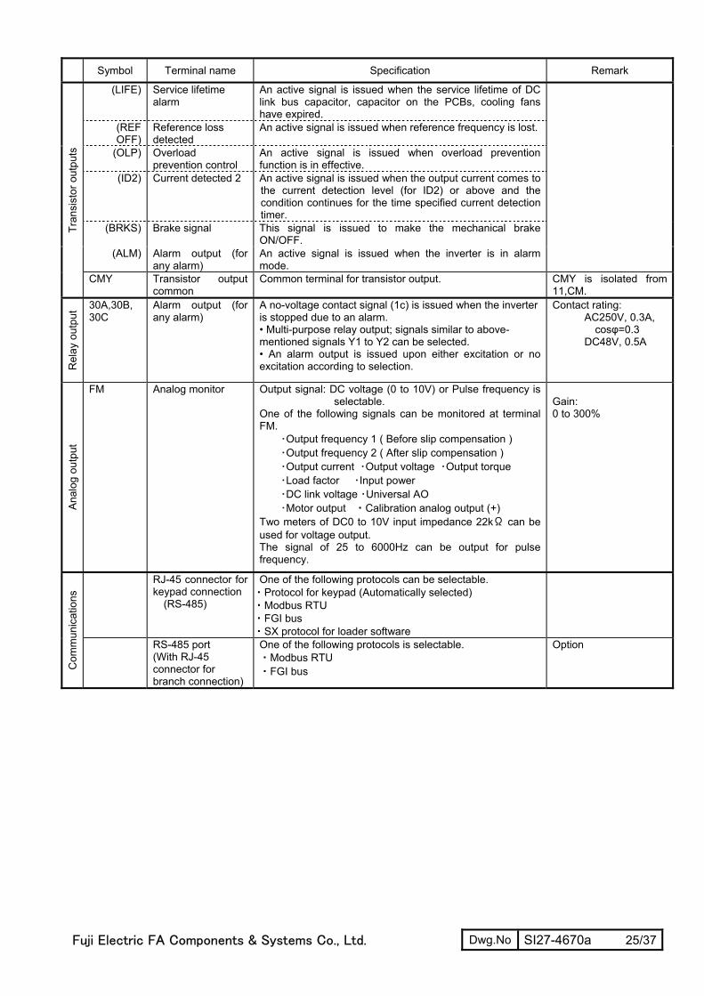
Symbol Terminal name Specification Remark
(LIFE) Service lifetime alarm
An active signal is issued when the service lifetime of DC link bus capacitor, capacitor on the PCBs, cooling fans have expired.
(REF OFF)
Reference loss detected
An active signal is issued when reference frequency is lost.
(OLP) Overload prevention control
An active signal is issued when overload prevention function is in effective.
(ID2) Current detected 2 An active signal is issued when the output current comes to the current detection level (for ID2) or above and the condition continues for the time specified current detection timer.
(BRKS) Brake signal This signal is issued to make the mechanical brake ON/OFF.
(ALM) Alarm output (for any alarm)
An active signal is issued when the inverter is in alarm mode.
Tr
ansi
stor
out
puts
CMY Transistor output common
Common terminal for transistor output. CMY is isolated from 11,CM.
Rel
ay o
utpu
t 30A,30B, 30C
Alarm output (for any alarm)
A no-voltage contact signal (1c) is issued when the inverter is stopped due to an alarm. • Multi-purpose relay output; signals similar to above-mentioned signals Y1 to Y2 can be selected. • An alarm output is issued upon either excitation or no excitation according to selection.
Contact rating: AC250V, 0.3A,
cosφ=0.3 DC48V, 0.5A
Anal
og o
utpu
t
FM Analog monitor Output signal: DC voltage (0 to 10V) or Pulse frequency is selectable.
One of the following signals can be monitored at terminal FM.
・Output frequency 1 ( Before slip compensation ) ・Output frequency 2 ( After slip compensation ) ・Output current ・Output voltage ・Output torque ・Load factor ・Input power ・DC link voltage ・Universal AO ・Motor output ・Calibration analog output (+)
Two meters of DC0 to 10V input impedance 22kΩ can be used for voltage output. The signal of 25 to 6000Hz can be output for pulse frequency.
Gain: 0 to 300%
RJ-45 connector for keypad connection
(RS-485)
One of the following protocols can be selectable. ・Protocol for keypad (Automatically selected) ・Modbus RTU ・FGI bus ・SX protocol for loader software
Com
mun
icat
ions
RS-485 port (With RJ-45 connector for branch connection)
One of the following protocols is selectable. ・Modbus RTU ・FGI bus
Option

Fuji Electric FA Components & Systems Co., Ltd. Dwg.No SI27-4670a 26/37
5. Basic Wiring Diagram
L1/R
L2/S
L3/T
[13]
G
U
V
W
M
(Note 3)
MCCBor
ELCB
(Note 2)
Three-phase200 to 240V
50/60Hzor
Three-phase380 to 480V
50/60Hz
Power supply
P(+)P1 N(-)
G
Main circuit
P(+)
P1
MC
(Note 1)
DCR
Motor
Grounding
Grounding
[12][11]
[C1][11]
[FM]
(FWD)
(CM)(REV)
(X1)(X2)(X3)(X4)(X5)
(CM)
(PLC)
3
2
1Voltage input0 to 10Vdc
Power supply forpotentiometer
(Note 5) Control circuit
<CMY><Y2><Y1>
(+)
(-)
Current input4 to 20mAdc
Anal
og
inpu
t
(Note 6)
Dig
ital
inpu
t
30A30B30C
30
Analog
Pulse
MCCB: Molded case circuit breakerELCB: Earth leakage circuit breakerMC: Magnetic contactorDCR: DC reactorDBR: Brake resistor
Tra
nsi
stor
Alarm output
DB
P DB
(Note 4)
DBR
(CM)
(THR)
DC0 to 10V
PTCDC4 to 20mA
RS-485 port
(option)
SINK
SOURCE
Meter
L1/L
L2/N
Single-phase200 to240V
50/60Hz
a
Fuji Electric FA Components & Systems Co., Ltd. Dwg.No SI27-4670a 27/37
Note 1:
When connecting a DC REACTOR (DCR) (option), remove the jumper bar from across the terminals [P1] and [P (+)].
Note 2:
Install a recommended molded-case circuit breaker (MCCB) or an earth leakage circuit breaker (ELCB) (with an overcurrent
protection function) in the primary circuit of the inverter to protect wiring. At this time, ensure that the circuit breaker protection
capacity is equivalent to or lower than the recommended capacity.
Note 3:
Install a magnetic contactor (MC) recommended for each inverter to separate the inverter form the power supply, apart from
the MCCB or ELCB, when necessary. Connect a surge suppressor in parallel when installing a coil such as the MC or solenoid
near the inverter.
Note 4:
(THR) is available when one of terminal functions for X1 to X5, FWD, REV (function code E01 to E05,E98 or E99) is set to the data “9”.
Note 5:
Frequency can be set by connecting a frequency setting device (external potentiometer) among the terminals 11, 12 and 13
instead of inputting voltage signal (0 to +10V DC, 0 to +5V DC or +1 to +5V DC) between the terminals 12 and 11.
Note 6:
For the control signal wires, use shielded or twisted wires. Ground shielded wires. To prevent malfunction due to noise, keep
the control circuit wiring away from the main circuit wiring as far as possible (recommended: 10cm or more), and never set
them in the same wire duct.
When crossing the control circuit wiring with the main circuit wiring, set them at right angles.
Note 7:
Three phases 4 wire shielded cable is recommended for motor wiring to reduce the noise emitted. Connect the motor
grounding wire to the inverter grounding terminal G.
6. Options Name Explanation
Multifunction keypad I/O checking added
DIO card 12bit binary reference frequency is possible.
PG interface card The interface card for PG feedback control or positioning function. With Fault detection for PG connection.
RS-485 communication card With RJ-45connector for branch connection
Field Bus option These are not available.

7.Function Codes
F codes: Fundamental Functions
CodeIncre-ment
UnitChange
whenrunning
Datacopying
Defaultsetting
F00 0: - - Y Y 01:2:3:
F01 0: UP/DOWN keys on keypad - - N Y 01: Voltage input to terminal [12] (-10 to +10 VDC)2:3:
5:7: Terminal command UP /DOWN control
11: DIO interface card (option)12: PG interface card (option)
F02 0: - - N Y 2
1: Terminal command FWD or REV2: RUN/STOP keys on keypad (forward)3: RUN/STOP keys on keypad (reverse)
F03 25.0 to 400.0 0.1 Hz N Y 60.0F04 25.0 to 400.0 0.1 Hz N Y 60.0F05 0: 1 V N Y2
80 to 240: 220160 to 500: 380
F06 80 to 240: 1 V N Y2 220160 to 500: 380
F07 0.00 to 3600 0.01 s Y Y 6.00
F08 0.00 to 3600 0.01 s Y Y 6.00
F09 0.1 % Y Y Dependingon the
invertercapacity
F10 1: - - Y Y 12:
F11 0.01 A Y Y1Y2
100% ofthe motor
ratedcurrent
F12 0.5 to 75.0 0.1 min Y Y 5.0F14 0: Disable restart (Trip immediately) - - Y Y 0
1: Disable restart (Trip after a recovery from power failure)
F15 Frequency Limiter (High) 0.0 to 400.0 0.1 Hz Y Y 70.0F16 (Low) 0.0 to 400.0 0.1 Hz Y Y 0.0F18 -100.00 to 100.00 *1 0.01 % Y* Y 0.00
0.0 to 60.0 0.1 Hz Y Y 0.0
F21 (Braking level) 0 to 100 1 % Y Y 0F22 (Braking time) 0.01 s Y Y 0.00
F23 0.1 to 60.0 0.1 Hz Y Y 0.5F24 (Holding time) 0.00 to 10.00 0.01 s Y Y 0.00F25 0.1 to 60.0 0.1 Hz Y Y 0.2F26 0.75 to 15 1 kHz Y Y 2F27 (Tone) 0: Level 0 (Inactive) - - Y Y 0
1: Level 12: Level 23: Level 3
separately powered cooling fan
Output an AVR-controlled voltage (for 400 V class series)Output an AVR-controlled voltage (for 200 V class series)Output an AVR-controlled voltage (for 400 V class series)
0.0 to 20.0(percentage with respect to "F05: Rated Voltage at Base Frequency1")Note: This setting takes effect when F37 = 0, 1, 3, or 4.
0.00: Disable0.01 to 100.001 to 135% of the rated current (allowable continuous drive current) ofthe motor
Base Frequency 1
Note: Entering 0.00 cancels the acceleration time, requiring externalsoft-start.
Note: Entering 0.00 cancels the deceleration time, requiring externalsoft-start.
Maximum Output Voltage 1
Acceleration/Deceleration Time 1
Rated Voltage at Base Frequency 1Output an AVR-controlled voltage (for 200 V class series)
Maximum Frequency 1
Enable both data protection and digital reference protection
Data Protection
Operation Method
Voltage input to terminal [C1] (V2 function) (0 to 10 VDC)
RUN/STOP keys on keypad (Motor rotational direction specifiedby terminal command FWD /REV )
Data setting range
Protection for Motor 1 For an inverter-driven motor, non-ventilated motor, or motor withFor a general-purpose motor with shaft-driven cooling fan
Name
Current input to terminal [C1] (C1 function) (4 to 20 mA DC)Sum of voltage and current inputs to terminals [12] and [C1](C1 function)
Disable both data protection and digital reference protectionEnable data protection and disable digital reference protectionDisable data protection and enable digital reference protection
Output a voltage in proportion to input voltage
Acceleration/Deceleration Time 2
(Overload detection level)
Bias (Frequency command 1)
Electronic Thermal Overload
Torque Boost 1
(Select motor characteristics)
(Thermal time constant) Restart Mode after MomentaryPower Failure
F20(Braking starting frequency)
Motor Sound (Carrier frequency)
Starting Frequency 1
DC Braking 1
Stop Frequency
0.00 : Disable0.01 to 30.00
Frequency Command 1(Speed 1)
(Mode selection)
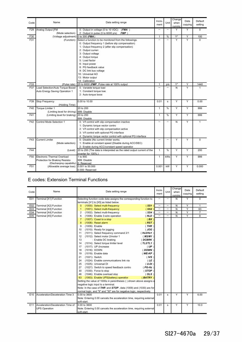
SI27-4670a 28/37
CodeIncre-ment
UnitChange
whenrunning
Datacopying
Defaultsetting
F29 Analog Output [FM] 0: Output in voltage (0 to 10 VDC) ( FMA ) - - Y Y 0(Mode selection) 2: Output in pulse (0 to 6000 p/s) FMP )
F30 (Voltage adjustment) 0 to 300 (FMA ) 1 % Y* Y 100F31 (Function) - - Y Y 0
0:1:2: Output current3: Output voltage4: Output torque5: Load factor6: Input power8: PG feedback value9: DC link bus voltage
10: Universal AO13: Motor output14: Calibration
F33 (Pulse rate) 25 to 6000 (FMP , Pulse rate at 100% output) 1 p/s Y* Y 1440F37 0: Variable torque load - - N Y 1
1: Constant torque load2: Auto-torque boost
F39 Stop Frequency 0.00 to 10.00 0.01 s Y Y 0.00(Holding Time)
F40 1 % Y Y 999
F41 1 % Y Y 999
F42 Control Mode Selection 1 0: - - N Y 11: Dynamic torque vector control2:3:4:
F43 Current Limiter 0: Disable (No current limiter works.) - - Y Y 0 (Mode selection) 1:
2: Enable during ACC/constant speed operationF44 (Level) 1 % Y Y 200
F50 1 to 900 1 kWs Y Y 999999: Disable
(Discharging capability) 0: ReservedF51 (Allowable average loss) 0.001 kW Y Y 0.000
E codes: Extension Terminal Functions
CodeIncre-ment
UnitChange
whenrunning
Datacopying
Defaultsetting
E01 - - N Y 0
E02 0 (1000): Select multi-frequency ( SS1 ) - - N Y 1E03 1 (1001): Select multi-frequency ( SS2 ) - - N Y 63E04 2 (1002): Select multi-frequency ( SS4 ) - - N Y 7E05 6 (1006): Enable 3-wire operation ( HLD ) - - N Y 8
7 (1007): Coast to a stop ( BX )8 (1008): Reset alarm ( RST )9 (1009): Enable ( THR )
10 (1010): Ready for jogging ( JOG )11 (1011): Select frequency command 2/1 ( Hz2/Hz1 )12 (1012): Select motor 2/motor 1 ( M2/M1 )13 : Enable DC braking ( DCBRK )14 (1014): Select torque limiter level ( TL2/TL1 )17 (1017): UP (Increase ( UP )18 (1018): DOWN ( DOWN )19 (1019): Enable data ( WE-KP )21 (1021): Switch ( IVS )24 (1024): ( LE )25 (1025): Universal DI ( U-DI )27 (1027): Switch to speed feedback control ( PG-Hz )30 (1030): Force to stop ( STOP )46 (1046): Enable overload stop ( OLS )63 (1063): Enable UPS(battery) operation ( BATRY )
E10 0.01 s Y Y 6.00
E11 0.01 s Y Y 10.0
Setting the value of 1000s in parentheses ( ) shown above assigns anegative logic input to a terminal.
0.00 to 3600Note: Entering 0.00 cancels the acceleration time, requiring externalsoft-start.0.00 to 3600Note: Entering 0.00 cancels the acceleration time, requiring externalsoft-start.
Note: In the case of THR and STOP , data (1009) and (1030) are fornormal logic, and "9" and "30" are for negative logic, respectively.
V/f control with slip compensation inactive
V/f control with slip compensation active
Enable at constant speed (Disable during ACC/DEC)
V/f control with optional PG interface
0.001 to 50.0000.000: Reserved
Name
Selecting function code data assigns the corresponding function toterminals [X1] to [X5] as listed below.
Data setting range
20 to 200 (The data is interpreted as the rated output current of theinverter for 100%.)
Dynamic torque vector control with optional PG interface
20 to 200999: Disable
Load Selection/Auto Torque Boost/Auto Energy Saving Operation 1
20 to 200999: Disable
Torque Limiter 1 (Limiting level for driving)
(Limiting level for braking)
Output frequency 1 (before slip compensation)Output frequency 2 (after slip compensation)
Enable communications link via
Select a function to be monitored from the followings.
Data setting range
Terminal [X4] Function
Acceleration/Deceleration Time 3
Acceleration/Deceleration Time ofUPS Operation
Electronic Thermal OverloadProtection for Braking Resistor
Terminal [X5] Function
Terminal [X1] Function
Name
Terminal [X2] FunctionTerminal [X3] Function
SI27-4670a 29/37
CodeIncre-ment
UnitChange
whenrunning
Datacopying
Defaultsetting
E16 1 % Y Y 999
E17 (Limiting level for braking) 1 % Y Y 999
E19 Reserved *2 0.000 to 0.100 - - Y Y 0.000E20 Terminal [Y1] Function - - N Y 57
E21 Terminal [Y2] Function 0 (1000): Inverter running ( RUN ) - - N Y 12E27 Terminal [30A/B/C] Function 1 (1001): Frequency arrival signal ( FAR ) - - N Y 99
2 (1002): Frequency detected ( FDT )3 (1003): ( LU )
4 (1004): Torque polarity detected ( B/D )5 (1005): Inverter output limiting ( IOL )6 (1006): ( IPF )
7 (1007): ( OL )10 (1010): Inverter ready to run ( RDY )12 (1012): ( SW52-2 )21 (1021): Frequency arrival signal 2 ( FAR2 )22 (1022): ( IOL2 )26 (1026): Auto-resetting ( TRY )28 (1028): ( OH )30 (1030): Service lifetime alarm ( LIFE )33 (1033): Reference loss detected ( REF OFF )35 (1035): Inverter output on ( RUN2 )36 (1036): Overload prevention control ( OLP )37 (1037): Current detected ( ID )38 (1038): Current detected 2 ( ID2 )49 (1049): Switched to motor 2 ( SWM2 )57 (1057): Brake signal ( BRKS )76 (1076): PG error detected ( PG-ERR )99 (1099): Alarm output (for any alarm) ( ALM )
E29 Frequency Arrival Delay Time 0.01 to 10.00 0.01 s Y Y 0.10E30 0.0 to 10.0 0.1 Hz Y Y 2.5
E31 0.0 to 400.0 0.1 Hz Y Y 60.0
E32 (Hysteresis width) 0.0 to 400.0 0.1 Hz Y Y 1.0E34
(Level) 0.01 A Y Y1Y2
E35 (Timer) 0.01 to 600.00 *1 0.01 s Y Y 10.00E37 0.01 A Y Y1
Y2
E38 (Timer) 0.01 to 600.00 *1 0.01 s Y Y 10.00E39 0.000 to 9.999 0.001 - Y Y 0.000
E40 PID Display Coefficient A -999 to 0.00 to 9990 *1 0.01 - Y Y 100E41 PID Display Coefficient B -999 to 0.00 to 9990 *1 0.01 - Y Y 0.00E42 LED Display Filter 0.0 to 5.0 0.1 s Y Y 0.5E43 0: Speed monitor (select by E48) - - Y Y 0
3: Output current4: Output voltage8: Calculated torque9: Input power
13: Timer15: Load factor16: Motor output
E45 0: - - Y Y 01:
E46 (Language selection) 0: Japanese - - Y Y 11: English2: German3: French4: Spanish5: Italian
E47 (Contrast control) 0 (Low) to 10 (High) 1 - Y Y 5E48 LED Monitor (Speed monitor item) 0: Output frequency (Before slip compensation - - Y Y 0
1: Output frequency (After slip compensation2: Reference frequency3: Motor speed in r/min4: Load shaft speed in r/min5: Line speed in m/min6: Constant feeding rate time
Auto-restarting after momentarypower failure
Inverter output limiting with delay
Frequency Detection (FDT)
Overload Early Warning/CurrentDetection
LED Monitor (Item selection)
Current Detection 2 (Level)
Coefficient for Constant FeedingRate Time
LCD Monitor *3 (Item selection)
100% ofthe motor
rated
Setting the value of 1000s in parentheses ( ) shown above assigns anegative logic input to a terminal.
100% ofthe motor
ratedcurrent
Motor overload early warning
Selecting function code data assigns the corresponding function toterminals [Y1], [Y2], and [30A/B/C] as listed below.
Undervoltage detected(Inverter stopped)
20 to 200999 : Disable
0.00 : DisableCurrent value of 1 to 200% of the inverter rated current
Bar charts for output frequency, current and calculated torqueRunning status, rotational direction and operation guide
0.00 : DisableCurrent value of 1 to 200% of the inverter rated current
MC control
Data setting range
20 to 200999 : Disable
(Detection level)
Heat sink overheat early warning
Name
Torque Limiter 2 (Limiting level for
Frequency Arrival (Hysteresis
SI27-4670a 30/37

CodeIncre-ment
UnitChange
whenrunning
Datacopying
Defaultsetting
E50 0.01 to 200.00 *1 0.01 - Y Y 30.00
E51 0.001 - Y Y 0.010
E52 Keypad (Menu display mode) 0: Function code data editing mode (Menus #0 and #1) - - Y Y 01: Function code data check mode (Menu #2)2: Full-menu mode (Menus #0 through #6)
E59 0: Current input (C1 function), 4 to 20 mADC - - N Y 01: Voltage input (V2 function), 0 to +10 VDC
E61 - - N Y 0
E62 0: None - - N Y 0(C1 function) 1: Auxiliary frequency command 1
E63 2: Auxiliary frequency command 2 - - N Y 0(V2 function)
E65 1 % Y Y 999
E98 Terminal [FWD] Function - - N Y 98E99 Terminal [REV] Function - - N Y 99
0 (1000): Select multi-frequency ( SS1 )1 (1001): Select multi-frequency ( SS2 )2 (1002): Select multi-frequency ( SS4 )6 (1006): Enable 3-wire operation ( HLD )7 (1007): Coast to a stop ( BX )8 (1008): Reset alarm ( RST )9 (1009): Enable ( THR )
10 (1010): Ready for jogging ( JOG )11 (1011): Select frequency command 2/1 ( Hz2/Hz1 )12 (1012): Select motor 2/motor 1 ( M2/M1 )13 : Enable DC braking ( DCBRK )14 (1014): Select torque limiter level ( TL2/TL1 )17 (1017): UP (Increase ( UP )18 (1018): DOWN ( DOWN )19 (1019): Enable data ( WE-KP )21 (1021): Switch ( IVS )24 (1024): Enable ( LE )25 (1025): Universal DI ( U-DI )27 (1027): Switch to speed feedback control ( PG-Hz )30 (1030): Force to stop ( STOP )46 (1046): Enable overload stop ( OLS )63 (1063): Enable UPS(battery) operation ( BATRY )98 : Run forward ( FWD )99 : Run reverse ( REV )
C codes: Control Functions
CodeIncre-ment
UnitChange
whenrunning
Datacopying
Defaultsetting
C01 0.0 to 400.0 0.1 Hz Y Y 0.0C02 Y Y 0.0C03 Y Y 0.0C04 (Hysteresis width) 0.0 to 30.0 0.1 Hz Y Y 3.0C05 Speed 2 (Run Speed) 0.00 to 400.0 0.01 Hz Y Y 0.00C06 Speed 3 (Maintenance Speed) Y Y 0.00C07 Speed 4 (Creep Speed) Y Y 0.00C08 Speed 5 (Run Speed) Y Y 0.00C09 Speed 6 (Run Speed) Y Y 0.00C10 Speed 7 (Maintenance Speed) Y Y 0.00C11 Speed 8 (Creep Speed) Y Y 0.00C19 UPS Operation Speed 0.00 to 400.0 0.01 Hz Y Y 0.00C20 Jogging Frequency 0.00 to 400.0 0.01 Hz Y Y 0.00C21 Timer Operation 0: Disable - - N Y 0
1: EnableC30 Frequency Command 2 0: UP/DOWN keys on keypad - - N Y 2
1: Voltage input to terminal [12] (-10 to +10 VDC)2: Current input to terminal [C1] (C1 function) (4 to 20 mA DC)3:
5: Voltage input to terminal [C1] (V2 function) (0 to 10 VDC)7: Terminal command UP /DOWN control
11: DIO interface card (option)12: PG interface card (option)
Selecting function code data assigns the corresponding function toterminals [12] and [C1] (C1/V2 function) as listed below.
3
Name
Reference Loss Detection (Continuous running frequency)
2
Terminal [C1] Extended Function
Terminal [C1] Extended Function
Coefficient for Speed Indication
Display Coefficient for Input Watt-hour Data
Terminal [C1] Signal Definition (C1/V2 Function)Terminal [12] Extended Function
Name
Note: In the case of THR and STOP , data (1009) and (1030) are fornormal logic, and "9" and "30" are for negative logic, respectively
Data setting range
[C1] (C1 function)Sum of voltage and current inputs to terminals [12] and
Data setting range
Selecting function code data assigns the corresponding function toterminals [X1] to [X5] as listed below.
0.000 (Cancel/reset)0.001 to 9999
Setting the value of 1000s in parentheses ( ) shown above assigns anegative logic input to a terminal.
0: Decelerate to stop20 to 120999: Disable
Jump Frequency 1
SI27-4670a 31/37
CodeIncre-ment
UnitChange
whenrunning
Datacopying
Defaultsetting
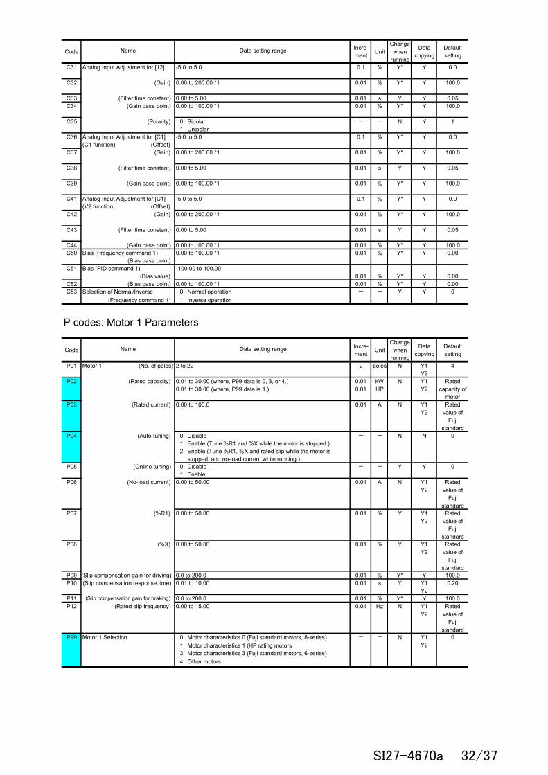
C31 -5.0 to 5.0 0.1 % Y* Y 0.0
C32 (Gain) 0.00 to 200.00 *1 0.01 % Y* Y 100.0
C33 (Filter time constant) 0.00 to 5.00 0.01 s Y Y 0.05C34 (Gain base point) 0.00 to 100.00 *1 0.01 % Y* Y 100.0
C35 (Polarity) 0: Bipolar - - N Y 11: Unipolar
C36 -5.0 to 5.0 0.1 % Y* Y 0.0(C1 function) (Offset)
C37 (Gain) 0.00 to 200.00 *1 0.01 % Y* Y 100.0
C38 (Filter time constant) 0.00 to 5.00 0.01 s Y Y 0.05
C39 (Gain base point) 0.00 to 100.00 *1 0.01 % Y* Y 100.0
C41 -5.0 to 5.0 0.1 % Y* Y 0.0(V2 function) (Offset)
C42 (Gain) 0.00 to 200.00 *1 0.01 % Y* Y 100.0
C43 (Filter time constant) 0.00 to 5.00 0.01 s Y Y 0.05
C44 (Gain base point) 0.00 to 100.00 *1 0.01 % Y* Y 100.0C50 Bias (Frequency command 1) 0.00 to 100.00 *1 0.01 % Y* Y 0.00
(Bias base point) C51 Bias (PID command 1) -100.00 to 100.00
(Bias value) 0.01 % Y* Y 0.00C52 (Bias base point) 0.00 to 100.00 *1 0.01 % Y* Y 0.00C53 0: Normal operation - - Y Y 0
(Frequency command 1) 1: Inverse operation
P codes: Motor 1 Parameters
CodeIncre-ment
UnitChange
whenrunning
Datacopying
Defaultsetting
P01 2 to 22 2 poles N Y1Y2
4
P02 (Rated capacity) 0.010.01
kWHP
N Y1Y2
Ratedcapacity of
motorP03 (Rated current) 0.00 to 100.0 0.01 A N Y1
Y2Rated
value ofFuji
standardP04 (Auto-tuning) 0: Disable - - N N 0
1:2:
P05 (Online tuning) 0: Disable - - Y Y 01: Enable
P06 (No-load current) 0.00 to 50.00 0.01 A N Y1Y2
Ratedvalue of
Fujistandard
P07 (%R1) 0.00 to 50.00 0.01 % Y Y1Y2
Ratedvalue of
Fujistandard
P08 (%X) 0.00 to 50.00 0.01 % Y Y1Y2
Ratedvalue of
Fujistandard
P09 (Slip compensation gain for driving) 0.0 to 200.0 0.01 % Y* Y 100.0P10 (Slip compensation response time) 0.01 to 10.00 0.01 s Y Y1
Y20.20
P11 0.0 to 200.0 0.01 % Y* Y 100.0P12 (Rated slip frequency) 0.00 to 15.00 0.01 Hz N Y1
Y2Rated
value ofFuji
standardP99 Motor 1 Selection 0: - - N 0
1: Motor characteristics 1 (HP rating motors)3:4: Other motors
Y1Y2
(Slip compensation gain for braking)
Name
Analog Input Adjustment for [12]
Selection of Normal/Inverse
Name
Analog Input Adjustment for [C1]
Analog Input Adjustment for [C1]
Motor 1 (No. of poles)
Data setting range
Motor characteristics 0 (Fuji standard motors, 8-series)
Motor characteristics 3 (Fuji standard motors, 6-series)
Enable (Tune %R1 and %X while the motor is stopped.)
0.01 to 30.00 (where, P99 data is 0, 3, or 4.)0.01 to 30.00 (where, P99 data is 1.)
Data setting range
Enable (Tune %R1, %X and rated slip while the motor isstopped, and no-load current while running.)
SI27-4670a 32/37

H codes: High Performance Functions
CodeIncre-ment
UnitChange
whenrunning
Datacopying
Defaultsetting
H03 Data Initialization 0: Disable initialization - - N N 01:2: Initialize motor 1 parameters3: Initialize motor 2 parameters
H04 Auto-reset (Times) 1 times Y Y 0
H05 (Reset interval) 0.5 to 20.0 0.1 s Y Y 5.0H06 Cooling Fan ON/OFF Control 0: Disable (Always in operation) - - Y Y 0
1: Enable (ON/OFF controllable)H07 0: Linear - - Y Y 4
1: S-curve (Weak)2: S-curve (Strong)3: Curvilinear4: S-curve (The setting from o61 to o66 becomes effective.)
H08 0: Disable - - N Y 0 1: Enable (Reverse rotation inhibited)2: Enable (Forward rotation inhibited)
H09 Starting Mode (Auto search) 0: Disable - - N Y 0
H11 Deceleration Mode 0: Normal deceleration - - Y Y 01: Coast-to-stop
H12 0: Disable - - Y Y 0Limiting 1: Enable
(Mode selection) H13 0.1 to 10.0 0.1 s Y Y1
Y2Depending
on theinvertercapacity
H14 (Frequency fall rate) 0.00: Deceleration time selected by F08 0.01 Hz/s Y Y 999
H16 (Allowable momentary 0.1 s Y Y 999power failure time)
H26 0: Disable - - Y Y 01:
H27 (Level) 0.00 to 5.00 0.01 V Y Y 1.60H28 Droop Control -60.0 to 0.0 0.1 Hz Y Y 0.0H30 Communications Link Function Run command - - Y Y 0
(Mode selection) 0: F021: F022: RS-4853: RS-4854: F025: RS-4856: RS-485 (option)7: RS-485 (option)8: RS-485 (option)
H42 1 - Y N -
H43 - - Y N -
H44 Startup Times of Motor 1 Indication of cumulative startup times - - Y N -
H45 Mock Alarm 0: 1:
- - Y N 0
H47 - - Y N Set atfactory
shippingH48 - - Y N -
H49 Starting Mode (Delay time) 0.0 to 10.0 s 0.1 s Y Y 0.0
H50 0.1 Hz N Y 0.0
H51 (Voltage) 1 V N Y2 0
H52 0.1 Hz N Y 0.0
H53 (Voltage) 1 V N Y2 0
H54 0.01 s Y Y 6.00
H56 0.00 to 3600 0.01 s Y Y 6.00H61 UP /DOWN Control 0: 0.00 - - N Y 1
(Initial frequency setting) 1: Last UP /DOWN command value on releasing run commandH63 Low Limiter (Mode selection) 0: - - Y Y 0
1:
H64 (Lower limiting frequency) 0.1 Hz Y Y 1.6
H65 Starting Speed (Soft start time) 0.01 s Y Y 0.00
Limit by F16 (Frequency limiter: Low) and continue to run
F01/C30
DisableEnable (Once a mock alarm occurs, the data automaticallyreturns to 0.)
0.0 (Depends on F16 (Frequency limiter: Low))0.1 to 60.00.00 to 60.00
0 to 240 : Output an AVR-controlled voltage (for 200 V class series)
Restart Mode after MomentaryPower Failure (Restart time)
Thermistor (Mode selection)
Capacitance of DC Link Bus
If the output frequency lowers below the one limited by F16(Frequency limiter: Low), decelerate to stop the motor.
Cumulative Run Time of Cooling
Frequency command
0.0 to 30.0
0 to 500 : Output an AVR-controlled voltage (for 400 V class series)
RS-485 RS-485 (option)
RS-485
0.0 : Cancel0.1 to 400.0
Instantaneous Overcurrent
0.0 : Cancel0.1 to 400.0
Acceleration/Deceleration Pattern
Rotational Direction Limitation
Initial Capacitance of DC Link BusCapacitor
Name
999 : Automatically determined by inverter
Indication for replacing capacitors on printed circuit boards (0000 toFFFF: Hexadecimal). Resettable.
RS-485 (option)
Enable (With PTC, the inverter immediately trips with 0h4displayed.)
F01/C30
F01/C30
RS-485 (option)
Indication for replacing DC link bus capacitor (0000 to FFFF:Hexadecimal)
Indication for replacing DC link bus capacitor (0000 to FFFF: Hexadecimal)Indication of cumulative run time of cooling fan for replacement
RS-485
Data setting range
Non-linear V/f Pattern 2
ACC/DEC Time (Jogging operation)
0 to 500: Output an AVR-controlled voltage (for 400 V class series)0.00 to 3600*ACC time and DEC time are common.
0: Disable1 to 10
0.01 to 100.00999: Follow the current limit command
Initialize all function code data to the factory defaults
0 to 240: Output an AVR-controlled voltage (for 200 V class series)
Cumulative Run Time of Capacitorson Printed Circuit Boards
Non-linear V/f Pattern 1
Deceleration Time for Forced Stop
SI27-4670a 33/37
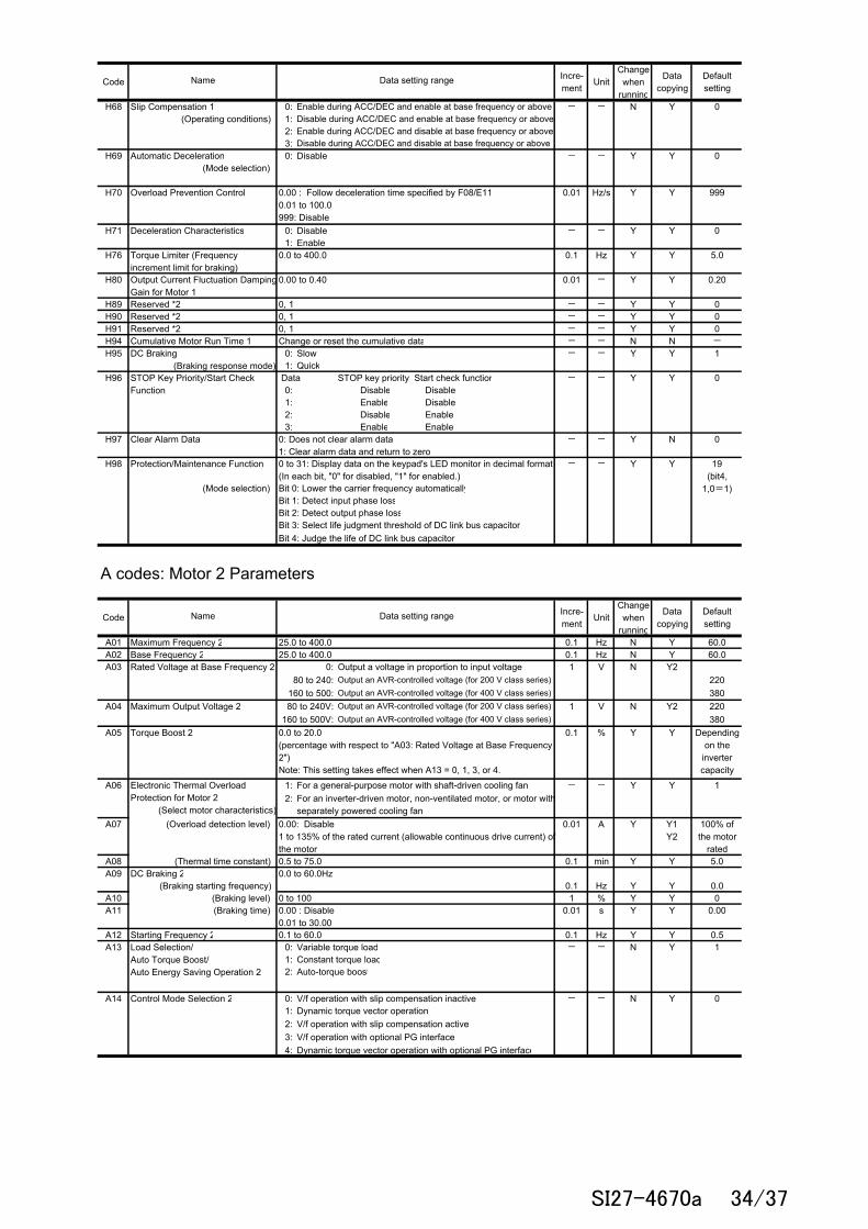
CodeIncre-ment
UnitChange
whenrunning
Datacopying
Defaultsetting
H68 Slip Compensation 1 0: - - N Y 0(Operating conditions) 1:
2:3:
H69 Automatic Deceleration 0: Disable - - Y Y 0(Mode selection)
H70 Overload Prevention Control 0.01 Hz/s Y Y 999
H71 Deceleration Characteristics 0: Disable - - Y Y 01: Enable
H76 0.0 to 400.0 0.1 Hz Y Y 5.0
H80 0.00 to 0.40 0.01 - Y Y 0.20
H89 Reserved *2 0, 1 - - Y Y 0H90 Reserved *2 0, 1 - - Y Y 0H91 Reserved *2 0, 1 - - Y Y 0H94 Cumulative Motor Run Time 1 Change or reset the cumulative data - - N N -
H95 0: Slow - - Y Y 11: Quick
H96 Data STOP key priority Start check function - - Y Y 00: Disable Disable1: Enable Disable2: Disable Enable3: Enable Enable
H97 Clear Alarm Data - - Y N 0
H98 - - Y Y
(Mode selection) Bit 0: Lower the carrier frequency automaticallyBit 1: Detect input phase lossBit 2: Detect output phase loss
Bit 4: Judge the life of DC link bus capacitor
A codes: Motor 2 Parameters
CodeIncre-ment
UnitChange
whenrunning
Datacopying
Defaultsetting
A01 Maximum Frequency 2 25.0 to 400.0 0.1 Hz N Y 60.0A02 Base Frequency 2 25.0 to 400.0 0.1 Hz N Y 60.0A03 0: 1 V N Y2
80 to 240: 220160 to 500: 380
A04 Maximum Output Voltage 2 80 to 240V: 1 V N Y2 220160 to 500V: 380
A05 Torque Boost 2 0.1 % Y Y Dependingon the
invertercapacity
A06 1: For a general-purpose motor with shaft-driven cooling fan - - Y Y 12:
A07 (Overload detection level) 0.01 A Y Y1Y2
100% ofthe motor
ratedA08 (Thermal time constant) 0.5 to 75.0 0.1 min Y Y 5.0A09 DC Braking 2 0.0 to 60.0Hz
(Braking starting frequency) 0.1 Hz Y Y 0.0A10 (Braking level) 0 to 100 1 % Y Y 0A11 (Braking time) 0.01 s Y Y 0.00
A12 Starting Frequency 2 0.1 to 60.0 0.1 Hz Y Y 0.5A13 0: Variable torque load - - N Y 1
1: Constant torque load2: Auto-torque boost
A14 Control Mode Selection 2 0: - - N Y 01: Dynamic torque vector operation2:3:4:
19(bit4,
1,0=1)
0 to 31: Display data on the keypad's LED monitor in decimal format(In each bit, "0" for disabled, "1" for enabled.)
Disable during ACC/DEC and enable at base frequency or aboveEnable during ACC/DEC and disable at base frequency or above
0: Does not clear alarm data1: Clear alarm data and return to zero
0.00 : Follow deceleration time specified by F08/E110.01 to 100.0999: Disable
Enable during ACC/DEC and enable at base frequency or above
Disable during ACC/DEC and disable at base frequency or above
Torque Limiter (Frequencyincrement limit for braking)
0.0 to 20.0(percentage with respect to "A03: Rated Voltage at Base Frequency2")Note: This setting takes effect when A13 = 0, 1, 3, or 4.
V/f operation with slip compensation inactive
Name
Bit 3: Select life judgment threshold of DC link bus capacitor
Data setting range
Output an AVR-controlled voltage (for 200 V class series)
Output an AVR-controlled voltage (for 200 V class series)Output an AVR-controlled voltage (for 400 V class series)
Output an AVR-controlled voltage (for 400 V class series)
Output a voltage in proportion to input voltage
Electronic Thermal OverloadProtection for Motor 2 (Select motor characteristics)
Output Current Fluctuation DampingGain for Motor 1
STOP Key Priority/Start CheckFunction
Rated Voltage at Base Frequency 2
Name
Load Selection/Auto Torque Boost/Auto Energy Saving Operation 2
V/f operation with optional PG interfaceDynamic torque vector operation with optional PG interface
V/f operation with slip compensation active
0.00 : Disable0.01 to 30.00
0.00: Disable1 to 135% of the rated current (allowable continuous drive current) ofthe motor
Data setting range
For an inverter-driven motor, non-ventilated motor, or motor withseparately powered cooling fan
Protection/Maintenance Function
DC Braking (Braking response mode)
SI27-4670a 34/37

CodeIncre-ment
UnitChange
whenrunning
Datacopying
Defaultsetting
A15 Motor 2 (No. of poles) 2 to 22 2 poles N Y1Y2
4
A16 (Rated capacity) 0.010.01
kWHP
N Y1Y2
Ratedcapacity of
motorA17 (Rated current) 0.00 to 100.0 0.01 A N Y1
Y2Rated
value ofFuji
standardA18 (Auto-tuning) 0: Disable - - N N 0
1:2:
A19 (Online tuning) 0: Disable - - Y Y 01: Enable
A20 (No-load current) 0.00 to 50.00 0.01 A N Y1Y2
Ratedvalue of
Fujistandard
A21 (%R1) 0.00 to 50.00 0.01 % Y Y1Y2
Ratedvalue of
Fujistandard
A22 (%X) 0.00 to 50.00 0.01 % Y Y1Y2
Ratedvalue of
Fujistandard
A23 (Slip compensation gain for driving) 0.0 to 200.0 0.01 % Y* Y 100.0A24 (Slip compensation response time) 0.01 to 10.00 0.01 s Y Y1 0.20A25 0.0 to 200.0 0.01 % Y* Y 100.0A26 (Rated slip frequency) 0.00 to 15.00 0.01 Hz N Y1
Y2Rated
value ofFuji
standardA39 Motor 2 Selection 0: - - N 0
1: Motor characteristics 1 (HP rating motors)3:4: Other motors
A40 Slip Compensation 2 0: - - N Y 0 (Operating conditions) 1:
2:3:
A41 0.00 to 0.40 0.01 - Y Y 0.20
A45 Cumulative Motor Run Time 2 Change or reset the cumulative data - - N N -
A46 Startup Times of Motor 2 Indication of cumulative startup times - - Y N -
J codes: Application Functions
CodeIncre-ment
UnitChange
whenrunning
Datacopying
Defaultsetting
J63 Overload Stop of UPS Operation 0: Torque - - Y Y 2(Detection value) 1: Current
2: Input powerJ64 (Detection level : UPS capacity) 20 to 200 0.1 % Y Y 100J65 (Mode selection) 0: Disable - - N Y 1
1: Decelerate to stop2: Coast to a stop
J66 (Operation condition) 0: - - Y Y 21: Enable at constant speed2: Enable anytime
J67 (Timer) 0.01 s Y Y 0.00J68 0 to 200 1 % Y Y 100
J69 (Brake release(OFF) frequency) 0.0 to 25.0 0.1 Hz Y Y 1.0J70 (Brake release(OFF) timer) 0.00 to 10.00 0.01 s Y Y 1.00J71 (Brake apply(ON) frequency) 0.0 to 25.0 0.1 Hz Y Y 1.0J72 (Brake apply(ON) timer) 0.00 to 100.00 0.01 s Y Y 1.00
Name
Enable (Tune %R1 and %X while the motor is stopped.)
(Brake release(OFF) current)
Name
Output Current FluctuationDamping Gain for Motor 2
0.00 to 600.00
Enable (Tune %R1, %X and rated slip while the motor isstopped, and no-load current while running.)
Braking Signal
Enable during ACC/DEC and disable at base frequency or aboveDisable during ACC/DEC and disable at base frequency or above
Data setting range
Enable at constant speed and during deceleration
Disable during ACC/DEC and enable at base frequency or aboveEnable during ACC/DEC and enable at base frequency or above
Motor characteristics 3 (Fuji standard motors, 6-series)
Y1Y2
(Slip compensation gain for braking)
0.01 to 30.00 (where, P99 data is 0, 3, or 4.)0.01 to 30.00 (where, P99 data is 1.)
Motor characteristics 0 (Fuji standard motors, 8-series)
Data setting range
SI27-4670a 35/37

y codes: Link Functions
CodeIncre-ment
UnitChange
whenrunning
Datacopying
Defaultsetting
y01 RS-485 Communication (Standard) 1 to 255(Station address) 1 - N Y 1
y02 (Communications error processing) 0: Immediately trip with alarm er8 - - Y Y 01:
3: Continue to runy03 (Timer) 0.0 to 60.0 0.1 s Y Y 2.0y04 (Baud rate) 0: 2400 bps - - Y Y 3
1: 4800 bps2: 9600 bps3: 19200 bps4: 38400 bps
y05 (Data length) 0: 8 bits - - Y Y 01: 7 bits
y06 (Parity check) 0: - - Y Y 01:2:3:
y07 (Stop bits) 0: 2 bits - - Y Y 01: 1 bit
y08 (No-response error detection time) 0: No detection 1 s Y Y 01 to 60
y09 (Response interval) 0.00 to 1.00 0.01 s Y Y 0.01y10 (Protocol selection) 0: Modbus RTU protocol - - Y Y 1
1: FRENIC Loader protocol (SX protocol)2: Fuji general-purpose inverter protoco
y11 RS-485 Communication (Option) 1 to 255(Station address) 1 - N Y 1
y12 (Communications error processing) 0: Immediately trip with alarm erp - - Y Y 01:
3: Continue to runy13 (Timer) 0.0 to 60.0 0.1 s Y Y 2.0y14 (Baud rate) 0: 2400 bps - - Y Y 3
1: 4800 bps2: 9600 bps3: 19200 bps4: 38400 bps
y15 (Data length) 0: 8 bits - - Y Y 01: 7 bits
y16 (Parity check) 0: - - Y Y 01:2:3:
y17 (Stop bits) 0: 2 bits - - Y Y 01: 1 bit
y18 (No-response error detection time) 0: No detection 1 s Y Y 01 to 60
y19 (Response interval) 0.00 to 1.00 0.01 s Y Y 0.01y20 (Protocol selection) 0: Modbus RTU protocol - - Y Y 0
2: Fuji general-purpose inverter protocoy98 Frequency command Run command - - Y Y 0
0: Follow H30 data Follow H30 data1: Via field bus option Follow H30 data2: Follow H30 data Via field bus option3: Via field bus option Via field bus option
y99 Frequency command Run command - - Y N 00: Follow H30 and y98 data Follow H30 and y98 data1: Via RS-485 link (Loader) Follow H30 and y98 data2: Follow H30 and y98 data Via RS-485 link (Loader)3: Via RS-485 link (Loader) Via RS-485 link (Loader)
Even parity (1 stop bit for Modbus RTU)Odd parity (1 stop bit for Modbus RTU)None (1 stop bit for Modbus RTU)
Even parity (1 stop bit for Modbus RTU)Odd parity (1 stop bit for Modbus RTU)None (1 stop bit for Modbus RTU)
None (2 stop bits for Modbus RTU)
Name Data setting range
Bus Link Function (Mode selection)
Loader Link Function(Mode selection)
None (2 stop bits for Modbus RTU)
Retry during the period specified by timer y03. If the retry fails,trip with alarm er8 . If it succeeds, continue to run.
Retry during the period specified by timer y13. If the retry fails,trip with alarm erp . If it succeeds, continue to run.
2:
Trip with alarm erp after running for the period specified by2:
Trip with alarm er8 after running for the period specified by
SI27-4670a 36/37

o codes: Option Functions
CodeIncre-ment
UnitChange
whenrunning
Datacopying
Defaultsetting
o01to - - - - - -
o21o31 Reserved *2 0000 to 7FFF 1 - Y Y 0000o32 Reserved *2 0000 to 7FFF 1 - Y Y 0000o40 Reserved *2 0.00 to 3.00 0.01 - Y Y 1.30o41 Reserved *2 0.00 to 10.00 0.01 s Y Y 0.05o42 Reserved *2 0.01 s Y Y 1.00o43 Reserved *2 0.01 s Y Y 0.20o44 Reserved *2 0.01 s Y Y 1.00o45 Reserved *2 0.01 s Y Y 1.00o46 Reserved *2 0.01 s Y Y 1.00o61 S-curve Setting 1 0 to 50% of max. frequency 1 % Y Y 20o62 S-curve Setting 2 1 % Y Y 20o63 S-curve Setting 3 1 % Y Y 20o64 S-curve Setting 4 1 % Y Y 20o65 S-curve Setting 5 1 % Y Y 20o66 S-curve Setting 6 1 % Y Y 20o75 MC Control
(Startup delay time) 0.00 to 10.00 0.01 s N Y 0.00o76 (MC OFF delay time) 0.00 to 10.00 0.01 s N Y 0.00o80 UPS Operation level 1 V N Y2
Edc 120 to 220: (for 200 V class series) 220 Edc 240 to 440: (for 400 V class series) 440
o81 0.00 to 3.00 0.01 - Y Y 1.50
*1 When you make settings from the keypad, the incremental unit is restricted by the number of digits that the LED monitor can display.(Example) If the setting range is from -200.00 to 200.00, the incremental unit is:"1" for -200 to -100, "0.1" for -99.9 to -10.0 and for 100.0 to 200.0, and "0.01" for -9.99 to -0.01 and for 0.00 to 99.99.
*2 These function codes and their data are displayed, but they are reserved for particular manufacturers. Unless otherwise specified, do not access thesefunction codes.
*3 These function codes are for use with an optional multi-function keypad
Torque Boost Gain for UPS Operation
Please refer to the InstructionManual of the option card.
Name Data setting range
Changing, validating, and saving function code data when the inverter is running Function codes are indicated by the following based on whether they can be changed or not when the inverter is running:
Notation Change when running Validating and saving function code data
Y* Possible If the data of the codes marked with Y* is changed with and keys, the change will immediately take effect; however, the change is not saved into the inverter's memory. To save the change, press the key. If you press the key without pressing the key to exit the current state, then the changed data will be discarded and the previous data will take effect for the inverter operation.
Y Possible Even if the data of the codes marked with Y is changed with and keys, the change will not take effect. Pressing the key will make the change take effect and save it into the inverter's memory.
N Impossible —
Copying data The data copying feature copies the function code data stored in the inverter's memory into the keypad's memory. With this feature, you can easily transfer the data saved in a source inverter to other destination inverters. The standard keypad does not support this feature. The optional multi-function keypad supports it with Menu #8 in Programming mode. If the specifications of the source and destination inverters differ, some code data may not be copied to ensure safe operation of your power system. Whether data will be copied or not is detailed with the following symbols in the "Data copying" column of the function code tables given below. Y: Will be copied unconditionally. Y1: Will not be copied if the rated capacity differs from the source inverter. Y2: Will not be copied if the rated input voltage differs from the source inverter. N: Will not be copied. (The function code marked with "N" is not subject to the Verify operation, either.) If necessary, set up uncopied code data manually and individually.
SI27-4670a 37/37