Embed Size (px)
Citation preview
PROJECT # FTEV 07-3002 DATE: 16 Sep 2011 DEPARTMENT OF THE AIR FORCE SPECIAL OPERATIONS COMMAND 1 SPECIAL OPERATIONS WING
SPECIFICATIONS FOR:
EXPAND DORM CHILLER PLANT
HURLBURT FIELD, FLORIDA

MS0109
I-1
INDEX
DIVISION 1 GENERAL 01000 General Requirements 01010 Summary of Work 01090 Reference Standards 01300 Submittals 01410 Testing Laboratory Services 01540 Green Procurement 01560 Environmental Protection 01580 Project Identification Sign 01600 Material and Equipment 01650 Starting of Systems 01700 Contract Closeout DIVISION 2 SITE WORK 02070 Selective Demolition 02110 Site Clearing & Grading 02222 Excavation & Trenching for Foundations, Slabs on Grade, & Utility Systems 02223 Backfilling & Compaction 02831 PVC Coated Chain Link Fencing System 02938 Sodding DIVISION 3 CONCRETE 03100 Concrete Formwork 03200 Concrete Reinforcement 03251 Construction, Isolation and Contraction Joints 03300 Cast-in-Place Concrete 03346 Concrete Floor Finish 03370 Concrete Curing 03732 Concrete Repair DIVISION 5 METALS 05120 Structural Steel DIVISION 7 THERMAL & MOISTURE PROTECTION 07900 Joint Sealers DIVISION 9 FINISHES 09900 Painting DIVISION 15 MECHANICAL 15000 Basic Mechanical Requirements 15050 Mechanical Demolition 15060 Supports and Anchors 15075 Mechanical Identification 15135 Gages 15185 Chemical Water Treatment 15260 Piping Insulation 15280 Equipment Insulation 15410 Plumbing Piping 15430 Plumbing Specialties Backflow Prevention Device Inspection and Maintenance Form 15510 Hydronic Piping/Water Treatment Systems 15515 Hydronic Specialties Backflow Prevention Device Inspection and Maintenance Form 15540 HVAC Pumps 15975 Direct Digital Control Systems 15990 Testing, Adjusting, and Balancing

MS0109
I-2
23 64 10 Water Chillers, Vapor Compression Type 23 65 00 Cooling Towers DIVISION 16 ELECTRICAL 16000 Basic Electrical Requirements 16111 Conduit 16123 Building Wire and Cable 16130 Boxes 16141 Wiring Devices 16145 Surge Suppressors 16170 Grounding and Bonding 16190 Supporting Devices 16195 Electrical Identification 16440 Disconnect Switches 16450 Secondary Grounding 26 29 23 Variable Frequency Drive Systems Under 600 Volts
END OF INDEX

MS1210
01000-1
SECTION 01000: GENERAL REQUIREMENTS PART 1 GENERAL 1.01 INTENT:
A. The intent of this project is to provide the Government with a fully complete and useable building meeting all the requirements for its intended use, constructed to high standards and the requirements of the Contract Documents. A fully complete and useable building is defined as one that is constructed to meet the aesthetic, functional and structural properties required by the drawings and specifications. All work shall be constructed to meet or exceed industry or government standards, whichever is more stringent. All construction shall be executed in a professional manner resulting in a finished product of highest quality. All materials, equipment, and other products used in the construction shall be new or approved recyclable materials from an approved source. All new work shall be maintained in a clean condition, and shall be installed plumb, square, true to line and grade, and shall conform to the stated dimensions, notes, schedules, etc. The work shall be properly secured, consistent in quality, fit and finish, and installation, etc.
1.02 APPLICABILITY:
A. This section of the specification is applicable to all sections that follow.
1.03 INTERPRETATION OF CONTRACT DOCUMENTS: A. Prospective bidders desiring further information, interpretation or clarification of the contract
documents shall forward a written request to the Contracting Officer. The Contracting Officer is the sole authority for interpretation of intent of work and for approval of quality of materials and workmanship. Failure to request the above shall not be the basis for a change order. DO NOT ASSUME THAT YOUR INTERPRETATION IS CORRECT.
1.04 CONFLICTS, DISCREPANCIES OR AMBIGUITIES: A. Prior to submittal of a bid or proposal by the prime/general contractor, it is expected that each
subcontractor, equipment and/or material supplier, and others associated with the project, shall have carefully examined as necessary, the drawings, specifications, and all addenda issued prior to the date of submission of the bid or proposal. Any and all conflicts, discrepancies or ambiguous language reasonably ascertainable from an inspection of the above and the project site that will affect the cost, quality, fit, finish, labor specified or required, equipment and/or materials specified or required, etc., necessary to fully complete the project and make it operational for it’s intended use, must immediately be brought to the attention of the prime/general contractor. The prime/general contractor must immediately notify the Contracting Officer in writing prior to submitting a bid or proposal and request written clarification of the conflict and/or discrepancy.
B. Conflicts, discrepancies and ambiguous language that are inconsistent with the intent as stated
above include but are not limited to: 1. Ambiguous notes or statements or drawings or details. 2. Conflicting information on the drawings and/or in the specifications. 3. Errors or inconsistencies in schedules. 4. Dimensional errors. 5. Incomplete notes or dimensions or schedules. 6. Extraneous notes, dimensions or schedules that conflict with the drawings or specifications. C. Conflicts, discrepancies or ambiguities brought to the attention of the Contracting Officer
AFTER award of contract WILL NOT be considered as a basis for a change in the work.
D. The intent of the above paragraphs is to increase the involvement of all persons associated with the project, particularly during the bid or proposal phase. Increased involvement during this phase will enhance the accuracy of the bid or proposal and reduce the potential for issuance of change orders during the construction phase.
1.05 DEFINITIONS: A. “Contract Documents": Contract Documents consist of the Contract, drawings and specifications, all
addenda issued prior to submission of the bid/proposal and all modifications and/or other directives issued after the award/execution of the contract. The intent of the Contract Documents is to provide the

MS1210
01000-2
Contractor with all items of work necessary for the proper execution and completion of the project. The items listed are complementary, what is required by one shall be as binding as if required by all. In the event of a conflict between the drawings and the specifications, the specifications shall take precedence over the drawings, unless otherwise noted on the drawings. The Contractor shall perform all work consistent with and reasonably inferable from the Contract Documents as necessary to produce the intended results.
B. “Government”: The government is the United States of America. The government is the owner of the
project. C. “Prime Contractor”: The Prime/General Contractor is the person or entity who is qualified, bonded and
insured, and who is responsible for preparing the bid/proposal and submitting it to the government. If the bid/proposal is accepted, the prime contractor will enter into a contract with the government to construct the work in accordance with the Contract Documents. The term “contractor” is used throughout the contract documents, and is synonymous with Prime/General Contractor, and means the contractor or the contractor’s authorized representative.
D. “Subcontractor”: A Subcontractor is a person or entity who prepares and submits a bid/proposal for a
portion of the work to the contractor for his use in preparing his bid/proposal. During the construction phase, the subcontractor has a direct contract with the contractor to perform a portion of the work.
E. “Material/Equipment Suppliers”: Material/equipment suppliers are person(s) or entities who prepare and submit a bid/proposal to the contractor for his use in preparing his bid/proposal. During the construction phase, the material equipment supplier has a direct contract with the contractor to provide certain materials or equipment to be incorporated into the work.
F. “Project”: The project is the total construction of the work to be performed under the contract documents
and may be the whole or part and which may include construction by the government.
G. “Work”: The term work means the providing of construction services required by the contract documents, and includes all labor, materials, equipment and other incidentals necessary to fulfill the contractor’s obligations. The work constitutes the whole project.
H. “Changes in the Work”: Changes in the work may be accomplished after award of contract without
invalidating the contract. Changes in the work shall be based upon a mutual agreement between the contractor and the government. Changes in the work shall be performed under applicable provisions of the contract documents unless otherwise provided for in the change. The time to complete the additional work shall also be a part of the agreement.
1.06 COORDINATION:
A. The prime contractor is responsible for the overall coordination of the project during the bid and or the proposal phase and the construction phase.
1. Coordinate bid and or the proposal phase to assure that all materials, labor, equipment, etc., to be used in the construction of the project and necessary for the completion of the prime contractor’s bid/proposal, as defined in 1.01 above, are included in the bids of the respective suppliers and/or subcontractors work, i.e., civil, architectural, plumbing, HVAC, or electrical.
2. Coordinate construction phase to assure efficient and orderly progression of the work. Coordination shall include, but is not limited to, periodic meetings between the contractor and subcontractors to coordinate the work of each trade one with the other, installation of one part of the work that is dependent on the installation of other components either before or after it's own installation, the materials and equipment needed to properly complete the work and ordering of those materials and equipment, preparation of schedules, layouts and phasing of the work as required to meet the government's stated needs, installation of and removal of temporary facilities, preparation and delivery of submittals including shop drawings, manufacturer’s product data, etc., scheduling of construction activities in the sequence required to obtain the best results, installation of different components within the allotted space to assure maximum accessibility for required maintenance or repair, periodic inspections of the work to assure compliance with the Contract Documents, visual inspections of the work to assure compliance with aesthetic requirements, maintenance and completion of all contract closeout documents including the coordination of supporting closeout documents by all subcontractors, maintenance and completion of Construction Data Worksheet, verification of new utility connections to each item of existing and new equipment, verify

MS1210
01000-3
measurements of existing and new work prior to installation of various components, proper storage of materials at the site particularly items requiring specific environmental conditions, protection of completed new work to minimize damage by other trades, cleaning, correction of punch list items of work after the final inspection, correction of warranty items during the warranty period, etc.
3. The prime contractor, each subcontractor, each equipment or material supplier and others who may be affiliated with the project are individually responsible for field verification of existing and new conditions that will affect their work, including the work of associated trades. Do not order, fabricate or install new items without field verification. Any discrepancy between the actual field dimension(s) and the size shown on the drawings, specifications, shop drawings, manufacturer’s product data, etc. must immediately be brought to the attention of the prime contractor, project inspector and Contracting Officer. The prime contractor shall request written direction from the Contracting Officer.
4. Prior to performing any Site work or work below grade, the Contractor must obtain a completed and signed copy of AF FORM 103, Base Civil Engineering Work Clearance Request.
5. Prior to bringing any lasers on Hurlburt Field, the contractor shall notify the Bio Environmental office 881-1822 and the Safety Office 884-7615.
B. Individual sections of this specification are taken from the Base Master Specification. Therefore, not all
products (materials, equipment, etc.) specified may be required to complete the construction of this project. In accordance with 1.05 above, the contractor, each subcontractor, equipment and/or material supplier, and others associated with the project, must carefully examine the drawings to determine which products are required to fully complete the work. See paragraph 1.04 Discrepancies.
1.07 CONSTRUCTION DATA WORKSHEET
A. The contractor must complete the checklist attached at the end of this section. 1. Section 1.a. General Data Required: The government will complete Category Code and Facility
number. 2. Section 1.b. Systems in Building: All.
1.08 METHODS:
A. The site shall be prepared, maintained, and operated by the contractor throughout the Work. Such preparation, maintenance, and operation include but are not limited to: 1. Preparation: Prevent damage to all existing construction, existing equipment and furnishings, existing
utilities and paved areas, and new items such as recently installed materials and equipment, new stored materials, trees/shrubs/landscape features identified to remain at the site, and privately owned vehicles in and around the work site. The contractor responsible for the damage will be held liable for the repair or replacement of the damaged item as directed by the Contracting Officer.
2. Safety and Security: Occupied and unoccupied facilities must be maintained in a safe manner to prevent the possibility of injury to the occupants and workmen. Upon completion of the days work, the contractor is responsible for securing the facility to prevent unlawful entry to the facility. If the interior of the facility or any equipment or furnishings are damaged due to the contractor's failure to properly secure the facility, the prime contractor and/or the subcontractor responsible for securing the facility will be held liable for the repair of the facility and replacement of the damaged equipment or furnishings as directed by the Contracting Officer.
3. Maintenance: Maintain the site in a neat and orderly manner to include daily trash/debris removal, stacking of material, control of surface drainage, mowing, and road sweeping.
4. Operation: Follow Occupational Safety and Health Administration requirements, US Army Corps of Engineers Safety and Health Requirements Manual EM 385-1-1, base law enforcement and base fire marshal requirements.
5. Trailers used for storage and/or temporary field offices shall be clean and well maintained and display only the name of the contractor or subcontractor.
1.09 CONSTRUCTION:
A. All work will be of professional quality. Intent of construction includes but is not limited to the following: 1. Utility connections shall be clean and complete. Contractor must request a utility outage from the
Contracting Officer no less than 3 working days prior to a scheduled outage for a single facility, and 14 days for outages affecting multiple facilities.
2. Backfilling and compaction will be performed so settling shall not occur. 3. All disturbed areas and all new graded areas shall be graded smooth and sodded. Seeding will be
permitted only if indicated on the drawings and/or approved by the Contracting Officer. Also, see other applicable sections(s) of the specification.

MS1210
01000-4
4. Construction shall be built to minimum industry tolerances unless otherwise noted and shall be square, true to line and grade, plumb and straight. Construct to the dimensions and elevations given on the drawings.
5. Finishes shall be consistent in color and texture, and shall cover all exposed surfaces, including obscure surfaces.
6. All work shall be constructed and/or installed in strict accordance with the manufacturer’s written instructions, copies of which must be included with submittal documents.
7. Road/pavement cuts are not permitted unless approved by the Contracting Officer. If approved, road/pavement cuts must be submitted to the 1Special Operations Civil Engineering Squadron, Engineering Flight (1 SOCES/CEC) in writing, two weeks prior to the scheduled road/pavement cut.
8. Under no circumstances will a utility outage or road cut be permitted without the required notification unless the Base Civil Engineer deems it an emergency.
9. Any contractor that connects to a Hurlburt Field fire hydrant for water usage must use an approved backflow preventer and provide proof to the 1 SOCES/CEV (Environmental Flight) through the Contracting Officer that they are using a certified backflow prevention device. The certificate must be current to within 12 months of the date of connection and through the duration of water usage. Certification must be by a Certified Backflow Tester certified by the State.
10. Temporary electric power, natural gas and water used by the contractor during construction shall be provided by the government at no cost to the contractor. The contractor shall provide temporary meters for each utility. Each temporary meter shall be read by the contractor monthly on the last working day of the month and submitted to the Hurlburt Field Energy Manager on that same day. At the completion of the project and acceptance by the government, the contractor shall remove the temporary meters and make the final connections to the utility.
1.10 CONSTRUCTION STANDARDS:
A. This project shall be constructed to conform to the latest edition of the following standards. 1. ASTM: American Society for Testing and Materials 2. ACI: American Concrete Institute 3. International Code Council, 2003 edition
a. International Building Code b. International Fuel Gas Code c. International Mechanical Code d. International Plumbing Code e. NFPA: National Fire Protection Association. f. NEC: National Electric Code g. Unified Facilities Criteria (UFC) UFC 4-010-01 dated 8 October 2003, DoD Minimum
Antiterrorism Standards for Buildings. h. Unified Facilities Criteria (UFC) UFC 3-600-01dated 17 April 2003 with change 16 January 2004,
Fire Protection Engineering for Facilities. i. Americans with Disabilities Act j. ASCE 7-98 k. 1 Special Operations Civil Engineer Squadron Design & Construction Standards. (Copy in 1
SOCES Engineering Flight office) l. Unified Facilities Criteria (UFC) UFC 3-210-10 dated 25 October 2004, Low Impact Development
.
B. The contractor is required to comply with all aspects of the Federal Aviation Regulation (FAR), Part 77, Objects Affecting Navigable Airspace, for all work associated with this contract. This includes, but is not limited to, the use of any and all equipment used to construct the facility and the facility itself. The contractor is required to obtain all necessary permits including FAA form 7460-1 (latest edition) and provide all necessary notices associated with this requirement. All work within the following areas must be coordinated in writing with the Contracting Officer 21 days in advance of commencement of the work: 1. LATERAL CLEARANCE AREA: A line 1000 feet from and parallel to the centerline of the runway.
2. TAXIWAY SETBACK: A line 200 feet from and parallel to the centerline of any taxiway. 3. APRON SETBACK: A line 125 feet from and parallel to the edge of the aircraft-parking apron. 4. CLEAR ZONE: A line 1500 feet from and parallel to the centerline of the runway beginning at the
runway threshold and continuing for a distance of 3000 feet north and south of the ends of the runway.
C. A copy of FAR Part 77, and permit applications may be obtained from: ARP Division ASO-600 Federal Aviation Administration

MS1210
01000-5
P. O. Box 20636 Atlanta, Georgia 30320 Phone 404-3056700 1.11 SUBSTITUTIONS: A. Throughout these specifications and/or on the drawings one or more "Trade Names" for a product may
be listed. When this occurs, all parties agree that the phrases: "or equal," "or approved equal," and "or equal as approved," follow each "Trade Name" listed. The contractor may submit substitute products, meeting the identified salient characteristics (physical and functional), to the Contracting Officer for review and approval. The term “Trade Names” includes Acceptable Manufacturers listed under PART 2 PRODUCTS of the specifications.
B. Approval Required:
1. The Contract is based on the standards of quality established in the Contract Documents. 2. All products proposed for use, including those specified by required attributes and performance shall
require approval by the Contracting Officer before being incorporated into the work. 3. Do not substitute materials, equipment, or methods unless such substitution has been
specifically reviewed and approved for this Contract by the Contracting Officer. 4. Refer to section 01600 for substitution submittal requirements.
C. Do not assume that materials, equipment or methods submitted, as a substitution, will be approved as equal. The Contracting Officer is the sole interpreter of the Contract Documents.
1.12 ASBESTOS: A. See section 01560, Environmental Protection 1.13 LEAD BASED PAINT A. See section 01560, Environmental Protection 1.14 HAZARDOUS MATERIALS AND WASTE
A. See section 01560, Environmental Protection 1.15 CONTRACT PROGRESS REPORT A. Contractor progress reports shall be made in a timely manner and in accordance with the contract
documents. B. Contractor shall use the Contract Progress Report form at the end of this section. As indicated on the
form, all listed items of work may not be applicable to this project. Contractor shall submit completed form to include only those items of work applicable to this project.
C. Item 73, “Close-Out Documents” has been assigned a value of 3%. This amount will be withheld from
final payment until such time as all project record documents (including "As-Built" drawings), operation & maintenance data, spare parts & maintenance products, warranties, maintenance service, etc., have been turned over to the government. The contractor and subcontractors are advised to prepare these documents as the work progresses and not wait until the end of the project. These documents must be turned over to the government prior to the final inspection. The withholding of payment is not a penalty but is being done to assure compliance with specification Section 01700 CONTRACT CLOSEOUT.
1.16 CONTRACT PROGRESS SCHEDULE A. The contractor must provide a copy of the Contract Progress Schedule for review by the Contracting
Officer and the Construction Manager no later than 5 calendar days after the issuance of the Notice to Proceed. If disapproved, the contractor shall resubmit the revised Contract Progress Schedule within 2 days of the date of the disapproval. The Contract Progress Schedule must be approved within 10 days of the date of the disapproval. No construction work shall start without an approved Contract Progress Schedule.
B. The Contract Progress Schedule must be based on the data in the Contract Progress Report attached to
the end of the section. C. In order to satisfy the contract requirements that work commence within 10 days of Notice to Proceed, the
contractor may commence the submittal process in accordance with Section 01300.

MS1210
01000-6
PART 2 NOT USED PART 3 NOT USED
END OF SECTION

MS1210
01000-7
CONSTRUCTION DATA WORKSHEET
1. GENERAL DATA REQUIRED:
A. PROJECT INFORMATION: Project No.: Contract No.: , Completion Date: _____ Category Code: ___________, Facility No.: ____________, Total Cost: ___________________ Liquidated Damages______________________________. Number of Floors: ______________ General Description: ___________________________________________________________________________ ___________________________________________________________________________ ___________________________________________________________________________ B. SYSTEMS IN BUILDING: Category Unit of Code Nomenclature Measure Amount Cost Description (If Required) 880-211 Closed Head Auto Sprinkler HD/SF ____/___ _______ ______________________ 880-217 AFFF PA Sprink Sys HD/SF ____/ ___ _______ _________________________ 880-221 Auto Fire Detection System SF/EA ____/ ___ _______ _________________________ (Include Pull Stations) 880-232 Foam Fire System EA ________ _______ _________________________ 872-841 Security Alarm System EA ________ ________ _________________________ 811-147 Electric Emergency Power Generator KW ________ ________ _________________________ Storage Tank for Heating GA ________ ________ _________________________ Or Generator Fuel (Type Fuel) Storage Tank for Heating GA ________ ________ _________________________ 821-115 Heating Plt 750/3500 MB MB ________ ________ _________________________ 821-116 Heating Plt over 3500 MB MB ________ ________ _________________________ Storage Tank for Heating GA ________ ________ _________________________ 890-125 A/C Plt less 5 TN TN ________ ________ _________________________ 890-121 A/C Plt 5 to 25 TN TN ________ ________ _________________________ 826-122 A/C Plt 25 to 100 TN TN ________ ________ _________________________ 826-123 A/C Plt Over 100 TN TN ________ ________ _________________________ 890-126 A/C Window Units SF/TN ____/ ___ ________ _________________________ 824-464 Gas Mains LF ________ ________ _________________________ 844-368 Water Supply, Non-Potable KG ________ ________ _________________________ 852-261 Veh. Parking (Ops) SY ________ ________ _________________________ 852-262 Veh. Parking (Non-Org) SY ________ ________ _________________________ 132-133 Pad, Equip SY ________ ________ _________________________ 132-134 Ant. Spt Stru EA ________ ________ _________________________ 890-272 EMCS Field Equip EA ________ ________ _________________________ 812-223 Prim Dist Line OH LF ________ ________ _________________________ Transformers KV ________ ________ _________________________ 812-224 Sec Dist Line OH LF ________ ________ _________________________ 812-225 Prim Dist Line UG LF ________ ________ _________________________ 812-226 Sec Dist Line UG LF ________ ________ _________________________ 812-926 Exterior Lighting EA ________ ________ _________________________ (Street or Parking area Lights) 812-928 Traffic Lights EA ________ ________ _________________________ 831-157 Industrial Waste Fuel Spill Collection (Oil/Fuel) KG ________ ________ _________________________ 831-169 Sewage Septic Tank KG ________ ________ _________________________ (Facility # it supports) 832-266 Sanitary Sewer Main LF ________ ________ _________________________ 832-267 Sanitary Sewage Pump Station SF ________ ________ _________________________ 842-245 Water Dist Mains LF ________ ________ _________________________ 843-314 Fire Protection Water Main LF ________ ________ _________________________ 843-315 Fire Hydrants EA ________ ________ _________________________ 851-143 Curbs & Gutters SY ________ ________ _________________________ (Transition between Road & Parking lot)

MS1210
01000-8
C. RELATED FACILITIES: Category Code Nomenclature UM Amount Cost _ Description (If Reqd.) 851-145 Driveway SY ________ ________ __________________ 851-147 Road SY ________ ________ __________________ 871-183 Storm Drain Disposal LF ________ ________ __________________ 872-245 Fence, Boundary LF ________ ________ __________________ 872-247 Fence, Security LF ________ ________ __________________ 872-248 Fence, Interior LF ________ ________ __________________ 852-289 Sidewalk SY ________ ________ __________________ 890-269 Cathodic Protection Sys EA ________ ________ __________________ 890-181 Utility Line Duct-Elec LF ________ ________ __________________ 890-181 Utility Line Duct-Comm LF ________ ________ __________________ 890-158 Load and Unload Platform EA ________ ________ _________________ 832-255 Industrial Waste Main LF ________ ________ __________________ This checklist includes only the basic general construction category codes. More detailed category code listing information is available through the Real Property office, 884-6167.

MS1210
01000-9
CONTRACT PROGRESS REPORT
CONTRACTOR ADDRESS
REPORT
NO. PERIOD COVERED PROJECT NO. / TITLE
FROM TO
CONTRACT AMOUNT CONTRACT NO. COMPLETION DATE
$ NOTE: ALL ITEMS LISTED MAY NOT BE APPLICABLE TO THIS PROJECT. CONTRACTOR SHALL SUBMIT COMPLETED FORM TO INCLUDE ONLY THOSE ITEMS THAT ARE APPLICABLE TO THIS PROJECT.
LINE NO.
WORK ELEMENTS % OF TOTAL JOB
% COMPLETED THIS PERIOD
% COMPLETE CUMULATIVE
1 MOBILIZATION
2 DEMOLITION - ARCHITECTURAL
3 ASBESTOS / LEAD ABATEMENT
4 SITE PREPARATION
5 SITE UTILITIES
6 SITE IRRIGATION SYSTEM
7 SITE FINISH GRADING
8 SITE LANDSCAPING
9 ASPHALT PAVING / BASE
10 CONCRETE CURB / GUTTER
11 CONCRETE BUILDING SLAB / VAPOR BARRIER
12 CONCRETE WALKS / LANDINGS
13 CONCRETE FOOTINGS
14 CONCRETE BEAMS / COLUMNS
15 MASONRY FOUNDATIONS
16 MASONRY SCREENWALLS
17 MASONRY VENEER
18 STRUCTURAL STEEL
19 MISCELLANEOUS METALS / HANDRAILS / GRATES
20 WOOD AND PLASTICS
21 WALL INSULATION
22 ROOF INSULATION
23 EIFS
24 WINDOWS
25 EXTERIOR DOORS
26 STOREFRONT
27 OVERHEAD COILING DOORS
28 INTERIOR DOORS
29 HARDWARE
30 EXTERIOR METAL STUDWALLS / SHEATHING
31 INTERIOR METAL STUDWALLS / SHEATHING
32 PAINTING
33 WALL COVERING
34 TOILET ACCESSORIES
35 TOILET PARTITIONS / URINAL SCREEN
36 SIGNAGE
37 RAISED ACCESS FLOOR

MS1210
01000-10
LINE NO.
WORK ELEMENTS % OF TOTAL % THIS PERIOD % CUMULATIVE
38 PRE-ENGINEERED METAL BUILDING (PEMB)
39 PEMB ROOF / FASCIA
41 ELEVATORS / CONVEYING SYSTEMS
42 DEMOLITION - MECHANICAL / PLUMBING
43 NEW WATER / SEWER / NATURAL GAS SERVICE
44 PLUMBING ROUGH-IN UNDER SLAB
45 HVAC ROUGH-IN UNDER SLAB
46 PLUMBING ROUGH-IN ABOVE SLAB
47 PLUMBING FIXTURE / TRIM-OUT
48 COMPRESSED AIR SYSTEM
49 PIPE AND DUCT INSULATION
50 DUCTWORK
51 HYDRONIC PIPING
52 FIRE SUPPRESSION
53 HVAC EQUIPMENT
54 GRILLES / DIFFUSERS/ TRIM-OUT
55 CONTROLS
56 TEST AND BALANCE
57 DEMOLITION - ELECTRICAL
58 ELECTRIC SERVICE TEMPORARY
59 TRANSFORMER
60 PRIMARY OVERHEAD ELECTRIC SERVICE
61 PRIMARY UNDERGROUND ELECTRIC SERVICE
62 SECONDARY OH ELECTRIC SERVICE
63 SECONDARY UG ELECTRIC SERVICE
64 ELECTRIC ROUGH-IN
65 COMM / LAN ROUGH-IN
66 FIRE DETECTION ROUGH-IN
67 FIRE DETECTION EQUIPMENT / TRIM-OUT
68 COMM / LAN TRIM-OUT
69 ELECTRIC FIXTURES / TRIM-OUT
70 EXTERIOR LIGHTING
71 BONDING
72 DEMOBILIZATION
73 CLOSE-OUT DOCUMENTS 3%
TOTAL
SCHEDULED AMOUNT THIS BILLING
TOTAL BID AMOUNT: SCHEDULED: ACTUAL:
INSPECTOR SIGNATURE: CONCUR NOT CONCUR (CIRCLE)
PROGRESS OR COMPLETION CERTIFICATE I HEREBY CERTIFY THAT THE CONTRACTOR HAS SATISFACTORILY COMPLETED THE INDICATED PERCENTAGE OF THE CONTRACT SPECIFICATIONS
SUBMITTED BY OR FOR CONTRACTOR: BASE CIVIL ENGINEER:
TYPE OR PRINT NAME AND TITLE SIGNATURE DATE
REVIEWED BY OR FOR CONTRACTING OFFICER TYPE OR PRINT NAME AND TITLE SIGNATURE DATE

MS1210
01010-1
SECTION 01010: SUMMARY OF WORK PART 1 GENERAL 1.01 RELATED SPECIFICATION SECTIONS: A. Section 01000 – GENERAL REQUIREMENTS. 1.02 WORK INCLUDED: A. The contractor shall furnish all labor, materials, tools, supervision and equipment and perform all
operations necessary to accomplish all work complete in place, as shown on the drawings, specified herein, or as needed.
Expand Dorm Chiller Plant (FTVE 07-3002): The purpose of the dorm chiller plant expansion design
is to connect buildings 90326, 90329, 90352, 90322 and 90349 to an existing central chiller plant, while adding another chiller and expanding the existing control system to serve the new equipment. Currently, the existing chiller plant serves buildings 90323, 90368, & 90369. This expansion will centralize chiller operation, maintenance, and repair requirements for the buildings listed and eliminate maintenance and repair/replacement requirements for the current air-cooled chillers and individual building chilled water pumps.
1.03 JOB DESCRIPTION: A. The work to be performed includes, but is not necessarily limited to, the following principal features:
1. Adding additional 350ton water cooled chiller and cooling tower with the necessary piping required. 2. Replacing the secondary chilled water pump at the chiller plant. 3. Adding a new primary pump and condenser water pump for the new 350ton water cooled chiller. 4. Abandoning chillers and removing pumps and 3-way valves at individual buildings 5. Adding 2-way valves at individual buildings 6. Trenching & Installing new chilled water piping to the additional buildings being added to the chiller
plant, including restoring any landscaping/sidewalks to pre-construction condition.
1.04 CONTRACTOR USE OF SITE AND PREMISES A. Limit use of site to allow Owner visitation and inspection. B. The contractor and subcontractors are permitted to use existing utilities available at the site. Use is
subject to approval by the Contracting Officer. The 1 Special Operations Civil Engineering Squadron must approve all connections. Connection to existing water mains must utilize a backflow preventer, certified within the 12 months prior to use on base.
1.05 DISPOSAL A. All scrap materials and debris shall be disposed of in an on- site dumpster. When full, it shall be
emptied at a legally approved dumpsite off- base. It shall be the responsibility of the contractor to provide the dumpster and for the selection of the dumpsite. Provide Contracting Officer with name(s) of waste disposal company and approved dumpsite.
1.06 STORAGE AREA A. Contractor lay-down/materials storage site shall be as shown on the drawings or as approved by the
Contracting Officer. B. A minimum of a 6 foot high temporary visual barrier shall surround the area. C. The area must be maintained in a reasonably clean manner. All empty boxes, paper and trash must be
deposited in the on-site construction dumpster. 1.07 SAFETY A. The pertinent sections of the following publications are applicable to all work on this project. 1. U.S. Army Corps of Engineers: EM 385-1-1, Safety and Health Requirements Manual. 2. Air Force Instruction (AFI) 91-301. 3. AFOSH Standard 48.139. See Specification Section 01000 General Requirements paragraph
1.06.A.5. 1.08 HAUL ROUTE AND LITTER A. The Contractor shall utilize only the designated haul route for the project for access to and from the
site as shown on the Drawings.

MS1210
01010-2
1.09 USE OF BARGE AREA
A. Use of the barge off loading area is not allowed except as approved, in writing, by the Contracting Officer. Contractor must request usage of the barge site, in writing, to the Contracting Officer a minimum of 30 days prior to expected deliveries. Contractor must also submit a schedule of all deliveries. Under no circumstances should the contractor assume such requests will be approved. Contractor should plan to have materials delivered by other means.
B. If usage of the barge site is approved, the contractor must meet the following requirements: 1. Crane boom height cannot exceed eighty (80) feet from mean water elevation. 2. Crane boom must have a red flag and an operational blinking obstruction light. 3. Contractor will be responsible for surrounding water quality per the State of Florida Regulations.
Prior to delivery of any barge/crane or tug, contractor must install full-depth turbidity barriers both east and west of the site to extend beyond limits of off loading operations.
4. Off loading operations will be during daylight hours only. Operations will not start before 0700 (7:00 AM) and boom must be lowered to deck height by 1700 hours (5:00 PM) each day.
5. Contractor is required to provide the name and number of a responsible party, and contact information of the tug/crane operator at site to both of the following:
a. The Contracting Officer. b. Hurlburt Tower: Hurlburt Tower – 884-4795. (If tower cannot be contacted notify the Airfield
Manager – Mr Bob Baker, 884-4491, Cell 598-1543). 6. Upon notification of inclement weather, off loading operations must cease and the boom lowered
to deck height. Do not raise boom until cleared by the Hurlburt Tower. All barges and equipment must be secured. Upon notification of Hurcon conditions, the contractor must remove all barges, cranes, tugs, and associated equipment from the site. The government will not be responsible for any delays or costs associated to weather.
7. If notified to do so by the Contracting Officer or Hurlburt Tower, operations must cease and the boom lowered to deck height. Under no circumstances should the boom be raised until cleared by the notifying authority. The government will not be responsible for any associated delays or costs.
C. If these requirements cannot be met, the contractor is prohibited from using the barge site. Failure to adhere to these requirements during operations will result in immediate revocation of site use at no expense to the government. Site must be maintained per specifications and contractor will be responsible for any and all clean-up after operations.
PART 2 PRODUCTS (Not Used) PART 3 EXECUTIONS 3.01 INSPECTION A. The contractor shall accomplish work in an orderly progression of steps to satisfy the performance
requirements of this specification. 3.02 HOURS OF WORK A. The normal hours of a workday shall be between 7:00 A.M. and 4:00 P.M., Monday through Friday,
except holidays and observed holidays. The contractor may elect, at his option, to work hours other than normal duty hours if approved by the Contracting Officer. All work time, other than normal working days, shall be requested in writing, 3 days in advance.
3.03 PHOTOGRAPHS
A. The contractor will take before and after photographs of the work. "Before" photos will be submitted before the start of work. "After" photos will be submitted before the acceptance of the work. A minimum of 24 photos of each will be required. Photos must show exterior and interior areas of the building that are to receive the new work. The intent is to show the amount of change. Photos may be submitted by the Air Force for design and construction awards. All photos taken shall be in digital format and submitted on CD. Submit one copy of before and after photos.
3.04 QUALITY CONTROL
A. The contractor shall establish and maintain quality control to assure compliance with Contract Documents, and maintain records of his quality control for materials, equipment and construction operations.

MS1210
01010-3
3.05 CONSTRUCTION LAYOUT & VERIFICATION: A. The contractor shall employ a Florida Registered Land Surveyor to layout the building and other site
features in accordance with the drawings. Potential problems that will affect the site geometry shall immediately be brought to the attention of the Contracting Officer.
B. Horizontal and Vertical Control shall conform to Hurlburt Field Datum: Horizontal NAD-83; Vertical NAVD-
88. C. Upon completion of the project and prior to the submission of the "As-Built" drawings (See Section 01700
Contract Closeout), the contractor shall employ a Florida Registered Land Surveyor to perform the following Horizontal Control by use of Global Positioning Satellite (GPS) to sub-meter accuracy, and Vertical Control using the above datum.:
1. Location of building corners. 2. Buried water mains, sanitary and/or storm water sewers including all valves, cleanouts, horizontal
turns, etc. 3. Elevations at top of manhole(s), lift stations, storm water structures or similar above ground
structures. 4. Invert elevations of all manholes and stub-outs intended for future connections to the system. 3.06 WARRANTY INSPECTION
A. A warranty inspection will be held thirty (30) days prior to the expiration of the contractor’s one-year warranty. The inspection will be held at the project site. Those in attendance shall include the contractor, the Contracting Officer, the project inspector, and the occupant. The purpose of this inspection will be to identify current or re-occurring problems associated with the project and past warranty calls and corrective action taken to remedy them. The contractor shall contact the Contracting Officer to determine the date of the inspection. The Contracting Officer shall contact the appropriate government agencies and confirm the date the inspection is to take place.
B. A list of problems identified at the inspection will be provided to all those in attendance. All problems must
be corrected to the satisfaction of the government prior to the expiration of the warranty
END OF SECTION

MS0109
01090-1
SECTION 01090 REFERENCE STANDARDS
PART 1 - GENERAL
1.01 RELATED SPECIFICATION SECTIONS:
A. Section 01000 - GENERAL REQUIREMENTS
1.02 SECTION INCLUDES A. Applicability of Reference Standards.
B. Provision of Reference Standards at site.
C. Source and acronyms used for Reference Standards in Contract Documents.
1.03 APPLICABILITY OF REFERENCE STANDARDS
A. For products or workmanship specified by association, trade, or Federal Standards, comply with requirements of the standard, except when more rigid requirements are specified or are required by applicable codes.
B. The publications listed in the various specification sections form a part of the specification to the extent
referenced. The publications are referred to in the text by basic designation only.
C. Use the latest standard, except when a specific date is specified.
D. Disregard payment provisions contained in any portion of the referenced specifications and standards.
E. If the specified reference standard(s) conflicts with the Contract Documents, request clarification from the Contracting Officer before proceeding.
1.04 PROVISION OF REFERENCE STANDARDS AT SITE
A. When required by individual specifications sections, obtain a copy of the standard. Maintain a copy at the jobsite during submittals, planning, and progress of the specific work until completion.
1.05 ABBREVIATIONS & NAMES
A. Where acronyms or abbreviations are used in the specifications or other Contract Documents, they mean the recognized name of the trade association, standards-generating organization, and authority having jurisdiction or other entity applicable. Refer to “Encyclopedia of Associations” published by Gale Research Co., available in most libraries.
1.06 SOURCE FOR REFERENCE STANDARDS
AASHTO American Association of State Highway and Transportation Officials 444 N. Capital St., NW, Suite 249 Washington, DC 20001
ACI American Concrete Institute P.O. Box 19150 Detroit, MI 48219 ACPA American Concrete Pipe Association 8300 Boone Blvd., #400 Vienna, VA 22182 ANSI American National Standards Institute 11 West 42nd St. New York, NY 10036
ASNT American Society for Non-destructive Testing 4153 Arlingate Plaza Columbus, OH 43228-0518

MS0109
01090-2
ASTM American Society for Testing and Materials 1916 Race Street Philadelphia, PA 19103
AWS American Welding Society P.O. Box 351040 Miami, FL 33135
AWWA American Water Works Association 6666 West Quincy Denver, CO 80235
CFR Code of Federal Regulations Order from: Superintendent of Documents Government Printing Office Washington, DC 20402-9371
CRSI Concrete Reinforcing Steel Institute 933 No. Plum Grove Rd. Schaumburg, IL 60173-4758
CS United States Department of Commerce Standard Order from: National Technical Information Service 5285 Port Royal Rd. Springfield, VA 22161
FAA Federal Aviation Administration Department of Transportation Order from: Superintendent of Documents Government Printing Office Washington, DC 20402-9371 For documents offered at no cost, order from: Dept. of Transportation ATTN: M443.2 400 Seventh St., SW Washington, DC 20590
FS Federal Specifications Order from: Standardization Documents Order Desk Bldg 4, Section D 700 Robbins Ave. Philadelphia, PA 19111-5094
FTM-STD Federal Test Method Standards Order from: Standardization Documents Order Desk Bldg 4, Section D 700 Robbins Ave. Philadelphia, PA 19111-5094
MS Military Specifications (MILSPEC) Standardization Documents Order Desk Bldg 4, Section D 700 Robbins Ave. Philadelphia, PA 19111-5094
MSS Manufacturers’ Standardization Society of the Valve and Fittings Industry

MS0109
01090-3
127 Park St., NE Vienna, VA 22180
NBS National Bureau of Standards (U. S. Department of Commerce) Gaithersburg, MD 20234
OSHA Occupational Safety and Health Administration (U.S. Department of Labor) Order from: Superintendent of Documents Government Printing Office Washington, DC 20402-9371 PART 2 - PRODUCTS: NOT USED. PART 3 - EXECUTION: NOT USED.
END OF SECTION

MS0109
01300-1
SECTION 01300: SUBMITTALS PART l GENERAL 1.01 RELATED SPECIFICATION SECTIONS: A. Section 01000 – GENERAL REQUIREMENTS 1.02 WORK INCLUDED:
A. Throughout the Contract Documents, the minimum acceptable quality of workmanship and materials has been defined by manufacturer's name and catalog number, reference to recognized industry and Government standards, or description of required attributes and performance.
B. Make all submittals required by the Contract Documents in a timely manner to allow construction of
the building within the allotted performance time. 1. Long lead items such as pre-engineered metal building systems, electrical and mechanical
systems, special equipment, etc. must be submitted within 15 days of Notice to Proceed. 2. All submittals must be made within 45 days of Notice to Proceed. 3. Late submittals that result in delayed delivery of materials and equipment, which will
affect the completion and acceptance of the building by the government, will not be a justification for a time extension.
4. Revise, submit and/or resubmit (submittals) as necessary to establish compliance with the specified requirements.
1.03 QUALITY ASSURANCE:
A. Coordination of Submittals: Prior to each submittal, carefully review and coordinate all aspects of each item being submitted and verify that each item and the submittal for it conforms in all respects with the requirements of the Contract Documents. By affixing his signature to each submittal, the contractor certifies that this coordination and verification has been performed.
B. Certificates of Compliance:
1. Certify that all materials used in the work comply with all specified provisions thereof. Certification shall not be construed as relieving the contractor from furnishing satisfactory materials if, after tests are performed on selected samples' the material is found to not meet specific requirements.
2. Show on each certification the name and location of the work, name and address of contractor, quantity and date or dates of shipment or delivery to which the certificate applies, and name of the manufacturing or fabricating company. An officer of the manufacturing or fabrication company shall sign certificates.
3. In addition to the above information, all laboratory test reports submitted with Certificates of Compliance shall show the date or dates of testing, the specified requirements for which testing was performed, and results of the test or tests.
PART 2 PRODUCTS 2.01 SHOP Drawings AND COORDINATION Drawings:
A. Shop Drawings: Make all shop Drawings accurately to a scale sufficiently large to show all pertinent aspects of the item and its method of connection to the work.
2.02 MANUFACTURER'S LITERATURE:
A. Where contents of submitted literature from manufacturers includes data not pertinent to the submittal, clearly indicate which portion of the contents is being submitted for review.
PART 3 EXECUTION 3.01 IDENTIFICATION OF SUBMITTALS:
A. General: Consecutively number all submittals.

MS0109
01300-2
B. Internal Identifications: On at least the first page of each copy of each submittal and elsewhere as required for positive identification, clearly indicate the submittal number in which the item was included.
C. Indicate FTEV Number, Project Title and Contract Number 3.02 COORDINATION OF SUBMITTALS:
A. General: Prior to submittal for approval, use all means necessary to fully coordinate all material including, but not necessarily limited to: 1. Determine and verify all interface conditions, catalog numbers and similar data. 2. Coordinate with other trades as required. 3. Clearly indicate all deviations from requirements of the Contract Documents.
B. Grouping of submittals: Unless otherwise specified, make all submittals in groups containing all
associated items to ensure that information is available for checking each item when it is received. Partial submittals will be rejected as not complying with the provisions of the Contract Documents and the contractor shall be strictly liable for all delays so occasioned.
C. Interior Finish Materials/Colors/Samples: All interior finish materials/colors/samples, including but not
limited to, flooring, base, paint/stain, wall coverings, acoustic ceiling/suspension system, acoustical treatment, window treatment, laminated plastic for base/wall cabinets/countertops, interior signage, etc., shall be submitted as a group (one submittal) to allow the government to review/approve/disapprove and select/coordinate the interior finish materials/colors prior to being incorporated into the work. Upon receipt of the government's approved selections, the contractor shall provide the government with actual samples of each item for the record, minimum size 4"x4", except laminate plastic chips shall be manufacturer's standard size.
D. Exterior Finish Materials/Colors/Samples: All exterior finish materials/colors/samples, including but not
limited to, brick, concrete masonry, exterior insulation finish system, stucco, paint/stain, roofing/flashing, exterior signage, pavers, windows, doors, etc., shall be submitted as a group (one submittal) to allow the government to review/approve/disapprove and /select/coordinate the exterior finish materials/colors prior to being incorporated into the work. Upon receipt of the government's approved selections, the contractor shall provide the government with actual samples of each item for the record, minimum size 4"x4".
3.03 SUBMITTAL APPROVAL:
A. General: Approval by the Contracting Officer shall not be construed as a complete check, but only that the general method of construction and detailing is satisfactory. Review and approval by government shall not relieve the contractor from responsibility for errors that may exist, or from liability for failure to comply with the intent of the Contract Documents.
B. Revisions After Approval: When a submittal has been approved, a re-submittal by the contractor for
the purpose of substitution of materials or equipment, will not be considered unless accompanied by an acceptable explanation as to why the substitution is necessary.
C. Unnecessary Submissions: When the contractor elects to provide the materials, equipment, etc., that
was used as the basis for the design and is the exact: Manufacture's name, catalog number, size, and finish as shown in the drawings or specified herein, no submittal is required. The contractor however shall submit a letter to the Contracting Officer stating that he will use the specified product. All field-testing associated with the material or equipment, etc. must be performed and submitted to the Contracting Officer for approval.
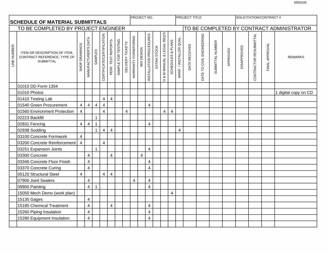
3.04 SCHEDULE OF MATERIAL SUBMITTALS. A. Assign numbers to these items to be submitted, beginning with the number 1 and continuing through the
last submittal. Items that are disapproved and require resubmittal shall be numbered with the original submittal number followed by R1 if the first resubmittal of the item, R2 if the second resubmittal, and so on, until final approval is given.
END OF SECTION
MS0105
PROJECT NO. PROJECT TITLE SOLICITATION/CONTRACT #
SCHEDULE OF MATERIAL SUBMITTALSTO BE COMPLETED BY PROJECT ENGINEER TO BE COMPLETED BY CONTRACT ADMINISTRATOR
LI
NE
NU
MB
ER
ITEM OR DESCRIPTION OF ITEM, CONTRACT REFERENCE, TYPE OF
SUBMITTAL
SH
OP
DR
AW
ING
S
MA
NU
FA
CT
UR
ER
'S D
AT
A
SA
MP
LES
CE
RT
IFIC
AT
E/C
ER
TIF
ICA
TIO
N
PE
RF
. TE
ST
RE
PO
RT
S
SA
MP
LE F
OR
TE
ST
ING
DE
LIV
ER
Y T
ICK
ET
S
WA
RR
AN
TY
FO
RM
/FO
RM
S
MIX
DE
SIG
N
INS
TA
LLA
TIO
N P
RO
CE
DU
RE
S
EX
TR
A S
TO
CK
O &
M M
AN
UA
L &
LE
GA
L R
EQ
'S
SC
HE
DU
LES
& P
LAN
S
MA
NF
. / IN
ST
ALL
ER
QU
AL.
DA
TE
RE
CE
IVE
D
DA
TE
TO
CIV
IL E
NG
INE
ER
ING
SU
BM
ITT
AL
NU
MB
ER
AP
PR
OV
ED
DIS
AP
PR
OV
ED
CO
NT
RA
CT
OR
RE
SU
BM
ITT
AL
FIN
AL
AP
PR
OV
AL
REMARKS
01010 DD Form 1354
01010 Photos 1 digital copy on CD
01410 Testing Lab 4 4
01540 Green Procurement 4 4 4 4 4
01560 Environment Protection 4 4 4 4 4
02223 Backfill 1
02831 Fencing 4 4 1 4
02938 Sodding 1 4 4 4
03100 Concrete Formwork 4
03200 Concrete Reinforcement 4 4
03251 Expansion Joints 1 4
03300 Concrete 4 4 4
03346 Concrete Floor Finish 4 4
03370 Concrete Curing 4 4
05120 Structural Steel 4 4 4
07900 Joint Sealers 4 4 4
09900 Painting 4 1 4
15050 Mech Demo (work plan) 4
15135 Gages 4
15185 Chemical Treatment 4 4 4
15260 Piping Insulation 4 4
15280 Equipment Insulation 4 4

MS0105
PROJECT NO. PROJECT TITLE SOLICITATION/CONTRACT #
SCHEDULE OF MATERIAL SUBMITTALSTO BE COMPLETED BY PROJECT ENGINEER TO BE COMPLETED BY CONTRACT ADMINISTRATOR
LI
NE
NU
MB
ER
ITEM OR DESCRIPTION OF ITEM, CONTRACT REFERENCE, TYPE OF
SUBMITTAL
SH
OP
DR
AW
ING
S
MA
NU
FA
CT
UR
ER
'S D
AT
A
SA
MP
LES
CE
RT
IFIC
AT
E/C
ER
TIF
ICA
TIO
N
PE
RF
. TE
ST
RE
PO
RT
S
SA
MP
LE F
OR
TE
ST
ING
DE
LIV
ER
Y T
ICK
ET
S
WA
RR
AN
TY
FO
RM
MIX
DE
SIG
N
INS
TA
LLA
TIO
N P
RO
CE
DU
RE
S
EX
TR
A S
TO
CK
O &
M M
AN
UA
L &
LE
GA
L R
EQ
'S
SC
HE
DU
LES
& P
LAN
S
MA
NF
. / IN
ST
ALL
ER
QU
AL.
DA
TE
RE
CE
IVE
D
DA
TE
TO
CIV
IL E
NG
INE
ER
ING
SU
BM
ITT
AL
NU
MB
ER
AP
PR
OV
ED
DIS
AP
PR
OV
ED
CO
NT
RA
CT
OR
RE
SU
BM
ITT
AL
FIN
AL
AP
PR
OV
AL
REMARKS
15410 Plumbing Piping 4 4 2
15430 Plumbing Specialties 4 4 4 4 2
15510 Hydronic Piping 4 4
15515 Hydronic Specialties 4 4 4 2
15540 HVAC Pumps 4 4 2
15975 Controls 4 4 4 2
15990 Test & Balance 4
236410 Chiller 4 4 4 4 2 4 2
236500 Cooling Tower 4 4 4 4 4 2
16111 Conduit 4
16123 Building Wire 4 4
16130 Boxes 4
16141 Wiring Devices 4
16170 Grounding 4 4 4
16440 Disconnect Switches 4
16450 Secondary Grounding 4
262923 VFD's 4 4 4 4 4 2
MS0109
01410-1
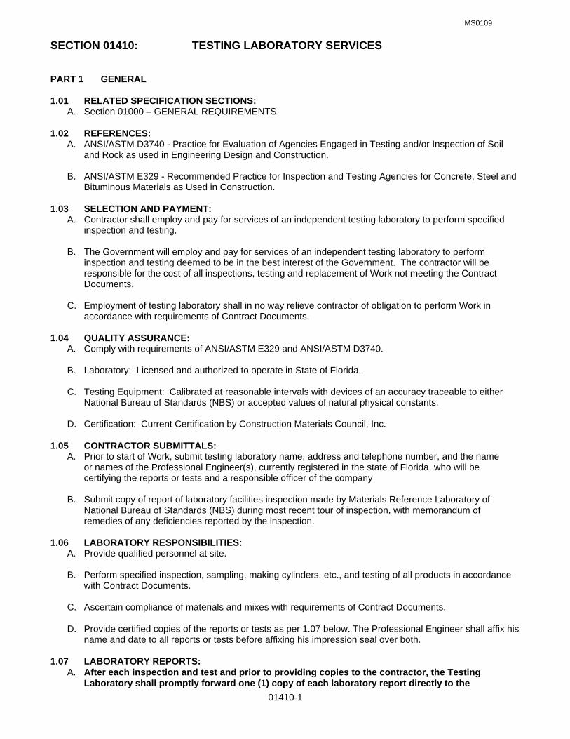
SECTION 01410: TESTING LABORATORY SERVICES PART 1 GENERAL 1.01 RELATED SPECIFICATION SECTIONS: A. Section 01000 – GENERAL REQUIREMENTS 1.02 REFERENCES:
A. ANSI/ASTM D3740 - Practice for Evaluation of Agencies Engaged in Testing and/or Inspection of Soil and Rock as used in Engineering Design and Construction.
B. ANSI/ASTM E329 - Recommended Practice for Inspection and Testing Agencies for Concrete, Steel and
Bituminous Materials as Used in Construction. 1.03 SELECTION AND PAYMENT:
A. Contractor shall employ and pay for services of an independent testing laboratory to perform specified inspection and testing.
B. The Government will employ and pay for services of an independent testing laboratory to perform
inspection and testing deemed to be in the best interest of the Government. The contractor will be responsible for the cost of all inspections, testing and replacement of Work not meeting the Contract Documents.
C. Employment of testing laboratory shall in no way relieve contractor of obligation to perform Work in
accordance with requirements of Contract Documents.
1.04 QUALITY ASSURANCE: A. Comply with requirements of ANSI/ASTM E329 and ANSI/ASTM D3740. B. Laboratory: Licensed and authorized to operate in State of Florida. C. Testing Equipment: Calibrated at reasonable intervals with devices of an accuracy traceable to either
National Bureau of Standards (NBS) or accepted values of natural physical constants. D. Certification: Current Certification by Construction Materials Council, Inc.
1.05 CONTRACTOR SUBMITTALS: A. Prior to start of Work, submit testing laboratory name, address and telephone number, and the name
or names of the Professional Engineer(s), currently registered in the state of Florida, who will be certifying the reports or tests and a responsible officer of the company
B. Submit copy of report of laboratory facilities inspection made by Materials Reference Laboratory of
National Bureau of Standards (NBS) during most recent tour of inspection, with memorandum of remedies of any deficiencies reported by the inspection.
1.06 LABORATORY RESPONSIBILITIES:
A. Provide qualified personnel at site. B. Perform specified inspection, sampling, making cylinders, etc., and testing of all products in accordance
with Contract Documents. C. Ascertain compliance of materials and mixes with requirements of Contract Documents.
D. Provide certified copies of the reports or tests as per 1.07 below. The Professional Engineer shall affix his
name and date to all reports or tests before affixing his impression seal over both. 1.07 LABORATORY REPORTS:
A. After each inspection and test and prior to providing copies to the contractor, the Testing Laboratory shall promptly forward one (1) copy of each laboratory report directly to the

MS0109
01410-2
Contracting Officer for record purposes. Mail to Contracting Officer, 16 CONS/LGCB, 350 Tully St., Hurlburt Field, FL 32544.
B. Contractor shall submit four (4) copies of each laboratory report as per Section 01300 to the Contracting
Officer for review and approval. C. Include:
1. Date issued. 2. Project title and number. 3. Name of inspector. 4. Date and time of sampling or inspection. 5. Identification of product and specifications section. 6. Location in the project. 7. Type of inspection or test. 8. Date of test. 9. Results of test. 10. Conformance with Contract Documents.
D. When requested by Contracting Officer, provide interpretation of test results.
1.08 LIMITS ON TESTING LABORATORY AUTHORITY:
A. Laboratory may not release, revoke, alter, or enlarge on requirements of Contract Documents. B. Laboratory may not approve or accept any portion of the Work. C. Laboratory may not assume any duties of the contractor. D. Laboratory has no authority to stop the Work.
1.09 CONTRACTOR RESPONSIBILITIES:
A. Notify laboratory of the location of the construction site and samples of materials proposed to be used, which require testing.
B. Provide laboratory all proposed mix designs. C. Cooperate with laboratory personnel and provide access to the Work, to manufacturer's literature and
other pertinent data. D. Provide incidental labor and facilities to provide access to Work to be tested, to obtain and handle
samples at the site or at source of products to be tested, to facilitate tests and inspections, storage and curing of test samples.
E. Notify laboratory a minimum of 24 hours prior to expected time for operations requiring inspection,
sampling, and testing services. PART 2 PRODUCTS (NOT USED) PART 3 PRODUCTS (NOT USED) END OF SECTION

MS0109
01540-1
SECTION 01540: GREEN PROCUREMENT PART 1 GENERAL 1.01 RELATED SPECIFICATION SECTIONS: A. Section 01000 – GENERAL REQUIREMENTS 1.02 GREEN PROCUREMENT & POLLUTION PREVENTION
A. Green Procurement is a mandatory component of the Air Force pollution prevention program. The AF Installation Pollution Prevention Program Guide includes this goal for Green Procurement: “100% of all products purchased each year in each of U.S. EPA’s ‘Guideline Item’ categories shall contain recycled materials meeting U.S. EPA’s Guideline Criteria.”
B. Currently, reporting of green procurement purchases is limited to contracts having a total value
greater than $100,000.00, which includes the purchase of any amount of U.S. EPA-designated items.
C. This document contains guidelines for implementing the RCRA, EO, DOD, and Air Force requirements 1.03 AUTHORITY & REFERENCES:
A. The Resource Conservation and Recovery Act (RCRA), section 6002 (42 U.S.C. 6962) B. Executive Order (EO) 13101, Greening the Government through Waste Prevention, Recycling, and
Federal Acquisition. C. Title 40, Code of Federal Regulations (CFR), Part 247, Comprehensive Procurement Guideline for
Products containing Recovered Material.
D. Federal Acquisition Regulations (FAR) 1.04 REGULATORY BACKGROUND A. Section 6002 of RCRA requires federal agencies to give preference in the acquisition process to
products and practices that conserve and protect natural resources and the environment. EO 13101 requires federal agencies to expand waste prevention and recycling programs, implement affirmative procurement programs for the United States Environmental Protection Agency (EPA) -designated items, and procure other environmentally preferable products and services. The stated purpose of the Green Procurement Program is to stimulate the market for recovered materials. As a result of EO 13101, the EPA issued the Comprehensive Procurement Guidelines (CPG’s) that have established the mandatory procurement by federal agencies of 36 items produced with recovered materials. The EPA has also issued Recovered Material Advisor Notices (RMANs) to accompany the CPGs and provide detailed information on the designated items.
B. Please direct all questions regarding the plan to the Contracting Officer for forwarding to the 1
SOCES/CEV Environmental Flight, 8844651.
1.05 DOD AND AIR FORCE REQUIREMENTS A. Green Procurement programs are required of all Air Force (USAF) installations. Department of
Defense (DOD) Instruction 4715.4, Pollution Prevention, calls for program establishment in accordance with RCRA and EO 12873. Green Procurement is also addressed in Air Force Instruction (AFI) 32-7080, Pollution Prevention Program, and the 24 July 1995 Air Force Pollution Prevention Strategy. The Strategy sets program goals, and the AFI provides program guidance.
1.06 SUBMITTALS
A. Submit under provisions of Sections 01000, 01300 and 01600.
B. Each contractor as defined in paragraph 1.09 Definitions must complete the form attached at the end of this section, indicating which products containing recycled or recovered products are going to be incorporated in the construction of this project. In accordance with paragraph 1.10 Exemptions, provide which exemption is applicable to each listed product.
MS0109
01540-2
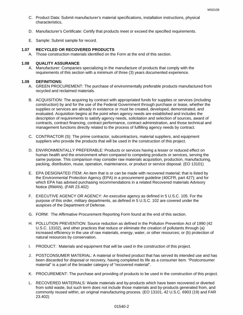
C. Product Data: Submit manufacturer’s material specifications, installation instructions, physical characteristics,
D. Manufacturer’s Certificate: Certify that products meet or exceed the specified requirements.
E. Sample: Submit sample for record.
1.07 RECYCLED OR RECOVERED PRODUCTS
A. Those construction materials identified on the Form at the end of this section. 1.08 QUALITY ASSURANCE
A. Manufacturer: Companies specializing in the manufacture of products that comply with the requirements of this section with a minimum of three (3) years documented experience.
1.09 DEFINITIONS: A. GREEN PROCUREMENT: The purchase of environmentally preferable products manufactured from
recycled and reclaimed materials.
B. ACQUISITION: The acquiring by contract with appropriated funds for supplies or services (including construction) by and for the use of the Federal Government through purchase or lease, whether the supplies or services are already in existence or must be created, developed, demonstrated, and evaluated. Acquisition begins at the point when agency needs are established and includes the description of requirements to satisfy agency needs, solicitation and selection of sources, award of contracts, contract financing, contract performance, contract administration, and those technical and management functions directly related to the process of fulfilling agency needs by contract.
C. CONTRACTOR (S): The prime contractor, subcontractors, material suppliers, and equipment
suppliers who provide the products that will be used in the construction of this project. D. ENVIRONMENTALLY PREFERABLE: Products or services having a lesser or reduced effect on
human health and the environment when compared to competing products or services, serving the same purpose. This comparison may consider raw materials acquisition, production, manufacturing, packing, distribution, reuse, operation, maintenance, or product or service disposal. (EO 13101)
E. EPA DESIGNATED ITEM: An item that is or can be made with recovered material; that is listed by
the Environmental Protection Agency (EPA) in a procurement guideline (40CFR, part 427); and for which EPA has advised purchasing recommendations in a related Recovered materials Advisory Notice (RMAN). (FAR 23.402)
F. EXECUTIVE AGENCY OR AGENCY: An executive agency as defined in 5 U.S.C. 105. For the
purpose of this order, military departments, as defined in 5 U.S.C. 102 are covered under the auspices of the Department of Defense.
G. FORM: The Affirmative Procurement Reporting Form found at the end of this section.
H. POLLUTION PREVENTION: Source reduction as defined in the Pollution Prevention Act of 1990 (42 U.S.C. 13102), and other practices that reduce or eliminate the creation of pollutants through (a) increased efficiency in the use of raw materials, energy, water, or other resources; or (b) protection of natural resources by conservation.
I. PRODUCT: Materials and equipment that will be used in the construction of this project.
J. POSTCONSUMER MATERIAL: A material or finished product that has served its intended use and has
been discarded for disposal or recovery, having completed its life as a consumer item. “Postconsumer material” is a part of the broader category of “recovered material”.
K. PROCUREMENT: The purchase and providing of products to be used in the construction of this project. L. RECOVERED MATERIALS: Waste materials and by-products which have been recovered or diverted
from solid waste, but such term does not include those materials and by-products generated from, and commonly reused within, an original manufacturing process. (EO 13101, 42 U.S.C. 6903 (19) and FAR 23.402)

MS0109
01540-3
M. RECYCLABILITY: The ability of a product or material to be recovered from or otherwise diverted from the
solid waste stream for the purpose of recycling. (EO 13101) N. RECYCLING: The series of activities, including collection, separation, and processing by which products
or other materials are recovered from the solid waste steam for use in form of raw materials in the manufacture of new products other than fuel for producing heat or power by combustion. (EO 13101)
O. RECYCLED MATERIAL: A material utilized in place of raw or virgin material in product manufacturing
consisting of materials derived from postconsumer waste, industrial scrap, material derived from agricultural wastes, and other items, all of which can be used in new product manufacturer. (EPA Guidelines & OFPP Policy Letter 92-4)
P. RECYCLED PRODUCT: A recycled product is one made completely or partially from waste materials or
by-products recovered or diverted from the solid waste stream. Q. SOLID WASTE: Garbage, refuse, sludges and other discarded materials including those from industrial,
commercial, and agricultural operations, and from community activities. This excludes solids or dissolved materials in domestic sewage or other significant pollutants in water resources, such as silt, dissolved or suspended solids in industrial waste water effluents, dissolved materials in irrigation return flow, etc. (EPA Guidelines)
R. SPECIFICATION (S): A clear and accurate description of the technical requirements for materials,
products, or services including the minimum requirement for materials’ quality and construction and any equipment necessary for an acceptable product. In general, specifications are in the form of written descriptions, drawings, prints, commercial designations, industry standards, and other descriptive references.
S. UNREASONABLE PRICE: If the cost of the recycled content product exceeds the cost of a non-recycled
item, the Air Force considers the cost to be unreasonable. (Air Force Affirmative Procurement Plan) T. VERIFICATION: Procedures used by procuring agencies to confirm both vendor estimates and
certifications of the percentages of recovered materials contained in the products supplied to them or to be used in the performance of a contract. (EPA Guidelines)
U. WASTE PREVENTION: Any change in the design, manufacturing, purchase, or use of materials or
products (including packaging) to reduce their amount or toxicity before they are discarded. Waste prevention also refers to the reuse of products or materials.
V. WASTE REDUCTION: Preventing or decreasing the amount of waste being generated through waste
prevention, recycling, or purchasing recycled and environmentally preferable products. 1.10 EXEMPTIONS
A. U.S. EPA recommends minimum content levels for those items listed at paragraph 1.11. The minimum content levels are indicated in the Form. These levels are mandatory for Air Force procurements unless one of the following exemptions applies. RCRA provides the following exemptions from the requirement to purchase EPA-designated items:
1. The product is not available from a sufficient number of sources to maintain a satisfactory level of
competition (i.e., available from two or more sources). 2. The product is not available within a reasonable period of time. 3 The product does not meet the performance standards in applicable specifications or fails to meet
reasonable performance standards of the procuring agency. 4. The product is not available at a reasonable price. For Air Force purposes, “unreasonable price” is
defined as follows: If the price of the recycled-content product exceeds the cost of a non-recycled item, then the price is considered unreasonable.
B. Each contractor is responsible for completion of the Form with respect to his or her work and products
being provided. Each contractor shall provide written documentation to support his/her decision not to

MS0109
01540-4
acquire items meeting the minimum content levels. This documentation shall be forwarded to the Contracting Officer for review and approval. In the event the documentation fails to support the contractor’s findings, the Contracting Officer shall return the documentation to the contractor citing the reason(s) for disapproval. The contractor shall resubmit and address the deficiencies.
1.11 U.S. EPA-DESIGNATED ITEMS
A. The 54 U.S. EPA-designated items are listed below. Not all of these items and the products listed under each item may be required in the construction of this project. Please refer to the drawings and specifications. The executed Form shall be used to demonstrate compliance with the stated procurement requirements.
1. PAPER PRODUCTS Item 1: All paper and paper products, excluding building and construction paper grades. 2. VEHICULAR PRODUCTS Item 2: Lubricating oils containing re-refined oil, including engine lubricating oils, hydraulic fluids,
and gear oils, but excluding marine and aviation oils. Item 3: Tires, excluding airplane tires. Item 4: Reclaimed engine coolants, excluding coolants used in non-vehicular applications
3. CONSTRUCTION PRODUCTS
Item 5: Building insulation products. Item 6: Structural fiberboard products for applications other than building insulation. Item 7: Laminated paperboard products for applications other than building insulation. Item 8: Cement and concrete, including products such as pipe and block, containing fly ash. Item 9: Cement and concrete, including concrete products such as pipe and block, containing
ground-granulated blast furnace (GGBF) slag. Item 10: Carpet made of polyester fiber for use in low- and medium-wear applications.
Item 11: Floor tiles containing recovered rubber or plastic. Item 12: Patio blocks containing recovered rubber or plastic.
Item 25: Shower and restroom dividers/partitions containing recovered steel or plastic. Item 26: Reprocessed and consolidated latex paint for specific uses. Item 37: Carpet cushion Item 38: Flowable fill. Item 39: Railroad grade crossing surfaces. 4. TRANSPORTATION PRODUCTS Item 13: Traffic barricades used in controlling or restricting vehicular traffic. Item 14: Traffic cones used in controlling or restricting vehicular traffic. Item 27: Parking stops. Item 28: Channelizers used as temporary traffic control devices. Item 29: Delineators used as temporary traffic control devices. Item 30: Flexible delineators used as temporary traffic control devices. 5. PARK AND RECREATION PRODUCTS Item 15: Playground surfaces containing recovered rubber or plastic. Item 16: Running tracks containing recovered rubber or plastic. Item 31: Plastic fencing. Item 40: Park benches and picnic tables. Item 41: Playground equipment. 6. LANDSCAPING PRODUCTS Item 17: Hydraulic mulch products containing recovered paper or recovered wood. Item 18: Compost made from yard trimmings, leaves, and/or grass clippings. Item 32: Garden and soaker hoses containing recovered rubber or plastic. Item 33: Lawn and garden edging containing recovered rubber or plastic. Item 42: Food waste compost. Item 43: Plastic lumber landscaping timbers and posts. 7. NON-PAPER OFFICE PRODUCTS Item 19: Office recycling containers. Item 20: Office waste receptacles.

MS0109
01540-5
Item 16: Plastic desktop accessories. Item 22: Toner cartridges. Item 23: Binders. Item 24: Plastic trash bags. Item 34: Printer ribbons (re-inked ribbons or re-inking equipment/service for ribbons). Item 35: Plastic envelops. Item 44: Solid plastic binders. Item 45: Plastic clipboards. Item 46: Plastic file folders. Item 47: Plastic clip portfolios. Item 48: Plastic presentation folders. 8. MISCELLANEOUS PRODUCTS Item 36: Pallets Item 49: Sorbents. Item 50: Industrial drums. Item 51: Awards and plaques. Item 52: Mats Item 53: Signage, including supports and posts. Item 54: Manual grade strapping.
1.12 APPLICABILITY A. These procedures apply to all contractors employed in the construction of this project. B. Please direct all questions regarding the plan to the Contracting Officer for forwarding to the 1
SOCES/CEV Environmental Flight, 8844651. 1.13 INTENT
A. The intent of this section is to increase the awareness of all contractors as to the availability of products manufactured from or that contain recycled materials, thereby increasing the use of these products in the construction of this project.
B. The various sections of the specifications contain references to products to be used in the construction of
this project. The listed product may or may not be manufactured from or contain recycled materials. Therefore all contractor(s), subcontractors, equipment suppliers and material suppliers are responsible for compliance with this specification and those items/products listed on the Form. Recycled products shall be used wherever possible subject to the exemptions as per paragraph 1.10.
C. Substitution of recycled materials or recycled products for specified products are subject to the provisions
of paragraph 1.06 Submittals (above) and Section 01000, paragraph 1.11.
PART II PRODUCTS 2.01 PARTIAL LIST OF PRODUCT SOURCES & INFORMATION A. GENERAL DATA: 1. GreenSpec Binder, Environmental Building News, www.ebuild.com 2. Certified Forest Products Council, www.cerifiedwood.org/ 3. Wiley Series in Sustainable Design, www.wiley.com/ 4. The Carpet and Rug Institute, www.carpet-rug.com/ 5. Information, McGraw-Hill, [email protected] 6. Florida Directory of Recycled Product Vendors,
www.2.dep.state.fl.us/waste/programs/rbac/downloads/rbac_dir.pd 7. Oikos Green Building Source, News, searchable products data base, library, www.oikos.com 8. Green Design Network, News, publications, databases, www.greendesign.net 9. Green Works Recycled Content7 Product Guide, detailed vendors directory,
www.metrokc.gov/greenworks/recycontent.htm> B. DIVISION 03, CONCRETE

MS0109
01540-6
1. GranCem, granulated blast-furnace slag, www.grancem.com/ 2. Syndesis, cement-based, pre-cast product workable with wood tools, www.syndesisinc.com/ C. DIVISION 04, MASONRY 1. Heble Building Systems, autoclaved aerated concrete blocks, www.heble.com/ 2 Ytong Florida Ltd., autoclaved aerated concrete blocks, www.ytong-usa.com/ D. DIVISION 06, WOOD & PLASTICS 1. Avonite, solid surfacing, www.avonite.com/ 2. Chemical Specialties, wood treatment, www.treatedwood.com/ 3. Homasote Company, structural fiberboard, www.homasote.com/ 4. Isoboard, fiberboard composed of straw fibers and non-toxic resins, www.isoboard.com/ 5. TrusJoist Mac Millan, engineered wood products, www.homasote.com/ E. DIVISION 07, Thermal & Moisture Protection 1. Duro-Last Roofing, recycled PVC walkway pads, 1-800-2480280 2. Johns Manville, Insulation products, www.jm.com/ 3. Majestic Skylines, rubber-based slate-look roofing for steep roofs, www.majesticskylines.com/ 4. Owens-Corning, insulation products, www.owenscorning.com/ F. DIVISION 08, DOORS & WINDOWS 1. Marvin Window & Door, windows, some meeting “Energy Star Label”, www.marvin.com/ 2. Pella, energy efficient windows, www/pella.com/ G. DIVISION 09, FINISHES 1. Armstrong World Industries, Inc.-Flooring Systems, www.armstrong-floors.com/ 2. Armstrong World Industries, Inc.-Ceiling Systems, www.ceilings.com/ 3. Benjamin Moore & Co., VOC free acrylic interior latex paint, www.benjaminmoore.com/ 4. CanFibre Group Ltd., all-green medium-density fiberboard, www.canfibre.com 5. Chemrex Inc., low-e interior paint, www.chemrex.com/ 6. Collins & Aikman Floor coverings, carpet with 100% post-consumer backing,
www.powerbond.com/ 7. DesignTex, Inc., polyester panel fabric made from 100% PET fiber, www.dtex.com/ 8. Dodge-Regupol, Inc., 100% recycled rubber-flooring, www.regupol.com/ 9. Eco-sensitive modular tile, vinyl tile with 100% recycled carpet-backing, www.powerbond.com/ 10. Environmental Stone Products, stone manufactured from 100% recycled glass,
www.environmentalstone.com/ 11. Glidden: residential interior latex paints 100% free of VOC, www.icipaintstores.com/ 12 Homasote Inc., sound barrier, www.homasote.com/ 13. Isoboard Enterprises, Inc. panel made from wheat straw and non-toxic resins, 1-503-2427345 14. Marley-Flexco Co., flooring made form 95% recycled truck and bus tires, www.marleyflexco.com/ 15. The Mat Factory, Inc., interlocking roll-up tiles made from 100% postconsumer tire rubber and PVC
plastic from electric cable covers, 1-949-6453122 16. Permafirm Pad Co., carpet pads made from almost 100% recycled content, 1-800-3446977 17. Sherwin Williams, VOC compliant paints and enamels, www.sherwin.com/ 18. SierraPine Limited, formaldehyde-free particleboard and medium density fiberboard containing
recycled/recovered wood fiber, www.sierrapine.com/ 19. Summittville Tiles, impervious porcelain tiles using feldspar tailings, www.summitville.com/ 20 Tectum, natural-fiber acoustical ceiling and wall panels, www.tectum.com/ 21. Tiles with natural fibers, tiles made of a bio-alloy material and natural fibers, www.maderatile.com 22. USG Interiors, Inc., synthetic gypsum board, www.usg.com/ 23. Decorative Architectural Tiles, floor, counter & wall tile made from 100 % postconsumer glass, 1-808-
8857812 24. Forbo, linoleum-flooring utilizing renewable resources, www.forbo.com/

MS0109
01540-7
H. DIVISION 10, SPECIALTIES 1. The Access Store, modular ramping system made from 100% recycled rubber,
www.accessstoe.com/ 2. BP Solar, photovoltaic modules and systems, www.bp.com/bpsolar/index 3. Mecho Shade Systems, interior shadecloths, www.mechoshade.com/ 4. R Control, structural insulated panel (SIP), www.mechoshade.com/ I. DIVISION 12, FURNISHINGS 1. Guilford of Maine, fabric from 100% recycled materials, www.terratex.com/ 2. Phenix Biocomposites, tabletops made from soy based products free of petrochemicals, 1-800-
3248187 3. Safe Solutions, LLC, furniture manufactured from waste wood, 1-970-2473333 J. DIVISION 14, CONVEYING SYSTEMS 1. Montgomery KONE, AC girlies elevators, www.montgomery-kone.com/ K. DIVISION 16, ELECTRICAL 1. Advance Transformer Company, linear reactor ballast, www.advancetransformer.com/ 2. Artemide Inc., energy efficient cold-cathode lighting, www.artemide.com/ 3. Edison Price Lighting, track mounted metal-halide PAR 30 &38 lamps, 1-212-5216995 4. Leviton Manufacturing Corporation, Inc., occupancy sensors, www.leviton.com/ 5. Phillips Lighting, energy efficient compact fluorescent lamps, www.phillips.com/lighting 6 Osram Sylvania, mercury-free lamps and energy efficient fluorescent lamps,
www.osramsylvania.com/ 7. Sensor Switch, lighting control occupancy sensors, www.sensorswitch.com/ 8. Venture Lighting, pulse-start high performance lamp and ballast system,
www.venturelighting.com/ PART III EXECUTION 3.01 INSTALLATION A. Install materials and systems in accordance with manufacturer’s written instructions and approved
submittals. Install materials and systems in proper relation to adjacent construction and with uniform appearance.
B. Coordinate with work of other sections. C. Restore damaged finishes and test for proper function. D. Clean and protect work from damage.
END OF SECTION

MS0109
01540-8
GREEN PROCUREMENT REPORTING FORM (PER EXECUTIVE ORDER 13101)
PROJECT NUMBER:___________________________________ BLDG NUMBER:_______________________________________ PROJECT MANAGER___________________________________ PROJECT INSPECTOR:_________________________________ CONTRACTOR:________________________________________ This form is to be completed by the Contractor and submitted through 1 SOCONS to 1 SOCEC. It is the responsibility of the 1 Special Operations Civil Engineering Squadron construction inspector to submit this data to 1 Special Operations Civil Engineering Squadron's Environmental Flight (CEV) who in-turn reports it to AFSOC MAJCOM IAW E.O. 13101, Federal Acquisition, Recycling, and Waste Prevention.
RECYCLED OR RECOVERED PRODUCT
% REQUIRED (MINIMUM)
% AVAIL (ACTUAL)
QUANTITY USED/UI
EXEMPTED 1,2,3,4
-ROCK WOOL INSUL 75% -FIBERGLASS INSUL 20-25% -LOOSE FILL/SPRAY ON INSUL 75% -PERLITE COMP BOARD INSUL 23% -PLASTIC RIGID FOAM INSUL 9% -GLASS FIBER REINF FOAM INSUL 6% -PHENOLIC RIGID FOAM INSUL 5% -STRUCTURAL FIBER BD 80-100% -LAMINATED PAPER BD 100% -CEMENT/CONCRETE (FLYASH) SEE SPEC -CARPET (PET) 25-100% -PATIO BLOCKS/RUBBER 90-100% -PATIO BLOCKS/PLASTIC 90-100% -FLOOR TILES/RUBBER 90-100% -FLOOR TILES/PLASTIC 90-100% -TRAFFIC CONES 50-100% -TRAFFIC BARRICADES 80-100% -PLAYGROUND SURFACES 90-100% -RUNNING TRACKS 90-100% -COMPOST 100% -WOOD-BASED HYDRAULIC MULCH
100%
-PAPER-BASED HYDRAULIC MULCH
100%
REPROCESSED LATEX PAINT WHITE, OFF-WHITE & PASTEL COLORS
20%
REPROCESSED LATEX PAINT GREY, BROWN, EARTHTONES & OTHER DARK COLORS
50-99%
CONSOLIDATED LATEX PAINT 100%
PLASTIC/RUBBER PARKING STOPS
100%
CONCRETE CONTAINING COAL FLY ASH PARKING STOPS
20-40%
CONCRETE CONTAINING GGBF PARKING STOPS
25-70%
PLASTIC SHOWER & RESTROOM DIVIDERS/PARTITIONS
20-100%

MS0109
01540-9
CERTIFICATION
I hereby certify the Statement of Work/Specifications for the requisition/procurement of all materials listed on this form comply with EPA standards for recycled/recovered materials content. _______________ _______________ _______________ Contractor Inspector Environmental Flight The following exemptions may apply to the non-procurement of recycled/recovered content materials: 1) The product does not meet appropriate performance standards 2) The product is not available within a reasonable time frame 3) The product is not available competitively (from two or more sources)
4) The product is only available at an unreasonable price (compared with a comparable non-recycled content product.)

MS0910
01560-1
SECTION 01560 ENVIRONMENTAL PROTECTION Part 1 GENERAL 1.01 RELATED SPECIFICATION SECTIONS: A. Section 01000 – GENERAL REQUIREMENTS 1.02. SECTION INCLUDES A. The environmental protection required for this contract. 1.03. REFERENCES A. The publications listed below form a part of this specification to the extent referenced. The publications are referred to in the text by the basic designation only. 1. CODE OF FEDERAL REGULATIONS (CFR)
29 CFR 1910.1200, Hazard Communication Standard 40 CFR 110, Discharge of Oil 40 CFR 112, Oil Pollution Prevention and Response 40 CFR 122, Municipal Separate Storm Sewer Systems, Phase I & II 40 CFR 125, Criteria and Standards for the National Discharge Elimination System (NPDES) 40 CFR 260-271, Resource Conservation and Recovery Act (RCRA) 40 CFR 260-279, Hazardous Waste and Used Oil Management 40 CFR 300, National Contingency Plan 40 CFR 355, Extremely Hazardous Substances 40 CFR 403, General Pretreatment Regulations for Existing and New Sources of Pollution 49 CFR 171-172, General Information, Regulations and Definitions, and Hazardous Waste Materials Tables
2. ENVIRONMENTAL PROTECTION AGENCY (EPA)
EPA PL 96-510, Comprehensive Environmental Response Compensation and Liability Act of 1980
3. FLORIDA ADMINISTRATION CODE (FAC)
FAC 62-25, Regulation of Stormwater Discharge FAC 62-150, Hazardous Substance Release Notification FAC 62-210, Stationary Sources – General Requirements FAC 62-212, Stationary Sources – Preconstruction Review FAC 62-346, Environmental Resource Permitting in Northwest Florida FAC 62-555, Permitting and Construction of Public Water Systems FAC 62-604, Collection System and Transmission Facilities FAC 62-730, Hazardous and Solid Waste Amendments (HSWA) to RCRA FAC 62-762, Aboveground Storage Tank Systems FAC 62-770, Petroleum Contamination Site Cleanup Criteria
4. HURLBURT FIELD INSTRUCTIONS AND DIRECTIVES
Hurlburt Field Instruction 32-700, Hazardous Material Management Hurlburt Field Directive for Mercury and Fluorescent Lamps Hurlburt Field Ozone Depleting Management Plan Hurlburt Field Spill Prevention Control and Countermeasure (SPCC) Plan Hurlburt Field Installation Restoration Program (IRP) Management Action Plan Hurlburt Field Hazardous Waste Management Plan Hurlburt Field Landscape Development Plan
5. HURLBURT FIELD INSTRUCTIONS AND DIRECTIVES AFI 23-204 Organizational Fuel Tanks
AFI 32-7044, Storage Tank Compliance 1.04 QUALITY ASSURANCE A. Contractor shall establish and maintain quality control for environmental protection of all items set forth herein. The Contractor shall record on daily reports any problems in complying with laws,

MS0910
01560-2
regulations, permit requirements, ordinances, and corrective action taken. The Contractor shall immediately inform the Contracting Officer of any environmental problem. 1.05 CONTRACTOR COMPLIANCE A. Permits: The contractor shall ensure that all required environmental permits are in their possession prior to start of construction and/or installing or operating any new or modified equipment or processes or disturbing or clearing any land area.
B. The contractor shall be responsible for operating within permit limits and abiding by all permit conditions. 1 SOCES/CEA shall be notified immediately of any exceedances of permit limits or violation of permit conditions. The contractor shall immediately notify 1 SOCES/CEA of any unforeseen environmental conditions, which may conflict with approved permits. Any certifications required by permits shall be the responsibility of the contractor. Copies of all permits and certifications shall be submitted to the 1 SOCES/CEA. C. All certifications, notices and documentation required by environmental
permits shall be the responsibility of the contractor, but must be coordinated through 1 SOCES/CEA prior to submittal to regulatory agencies.
1. Sanitary Sewer Permit: The government will provide a copy of the permit to the contractor
prior to start of construction. After construction, the line will not be put into use until the permit clearance has been applied for and obtained. All necessary paperwork (Certification of Completion Form, as-builts, etc.) will be submitted through 1 SOCES/CEA. FDEP has 30 days to review. Work is not considered complete until the permit clearance has been applied for and obtained.
2. Potable Water Permit: The government will provide a copy of the permit to the contractor prior to start of construction. After construction, the line will not be put into use until the permit clearance has been applied for and obtained. For phased projects a permit clearance can be obtained for each phase by submitting a certification of completion package for each phase as a partial completion on the entire permitted project. All necessary paperwork (Certification of Completion Form, as-builts, bacteriologicals, pressure test results, etc) will be submitted through 1 SOCES/CEA. FDEP has 30 days to review. Work is not considered complete until the permit clearance has been applied for and obtained.
3. Irrigation Permit: The government will provide a copy of the permit to the contractor prior to start of construction. After construction, the system will not be put into use until the permit clearance has been applied for and obtained. All necessary paperwork (Certification of Completion Form, as-builts, etc) will be submitted through 1 SOCES/CEA. FDEP has 30 days to review. Work is not considered complete until the permit clearance has been applied for and obtained.
4. Wetland Permit: The government will provide a copy of the permit to the contractor prior to start of construction. Prior to start of any construction in a wetland, a Joint Application for Works in the Waters of Florida must be completed by the contractor. Completion of the application package to include site plan, signed/sealed drawings and appropriate fees must be coordinated through 1 SOCES/CEAN. The application must note all best management practices (BMP's) and include locations of silt screens and hay bales. State has gets 30 days to request additional information. All necessary paperwork (Certification of Completion Form, as-builts, etc) will be submitted through 1 SOCES/CEA. FDEP has 30 days to review. Work is not considered complete until the permit clearance has been applied for and obtained.
5. Generic Stormwater Permit for Stormwater Discharge from Large and Small Construction
Activities, F.A.C. 62-621; and Individual Environmental Resource Permit F.A.C. 62-346 if applicable : a. Prior to start of Construction:
1. The government will provide a copy of the permit to the contractor prior to start of construction. Prior to start of any site work the contractor shall submit to 1SOCES/CEA; 1 copy of the Notice of Intent (NOI) Form 62-621.300(4)(b); proof of fee payment; 1 copy of the signed Stormwater Pollution Prevention Plan (SWPPP)

MS0910
01560-3
and map; 1 copy of the letter from the regulatory agency issuing the permit for the project;
2. If F.A.C. 62-346 is applicable: 2 copies of application package signed and sealed with Form 62-346.900(1); proof of fee payment; 1 copy regulatory agency letter issuing permit number; 1 copy of the proof of submittal to regulatory agency Form 62-346.900(3) of the Construction Commencement Notice at least 48 hours prior to start of construction.
b. During Construction::
1. The contractor shall provide to 1SOCES/CEA at the end of each month, signed weekly and storm event inspection reports; and the Notice of Termination (NOT) Form 62-621.300(6) within 14 days of final stabilization of the site. Copies of the reports must be kept on-site.
2. If F.A.C. 62-346 is applicable: 1 copy of Form 62-346.900(4) As-Built Certification by the Engineer of record within 30 days after completion of construction; 1 copy Form 62-346.900(6) request for conversion of Stormwater Management Permit Construction Phase to Operation and maintenance Phase within 30 days after completion of construction.
c. Upon completion of the storm water system the contractor shall notify 1SOCES/CEA to inform the engineer of record that the system is complete. The engineer of record will prepare the all necessary paperwork, (Certification of Completion Form, as-builts, etc) to be submitted to the regulatory agency through 1 SOCES/CEA. FDEP has 30 days to review. Work is not considered complete until the permit clearance has been applied for and obtained.
6. Copies of all required forms and guidance can be found at http://www.dep.state.fl.us/ and
http://www.nwfwmd.state.fl.us/. Part 2 PRODUCTS (NOT USED) Part 3 EXECUTION 3.04 SUBMITTALS
A. The Contractor shall submit an Environmental Protection Plan within 15 days after receipt of the notice to proceed. Approval of the Contractor's plan will not relieve the Contractor of responsibility for adequate and continuing control of pollutants and other environmental protection measures. The contractor shall obtain approval by the Contracting Officer prior to the start of construction, modification, or demolition for all project facilities and/or equipment. The plan shall include, but shall not be limited to, the following: 1. Legal Requirements: A list of Federal, State, and local laws, regulations, and permits
concerning environmental protection, pollution control and abatement that are applicable to the Contractor's proposed operations and the requirements imposed by those laws, regulations, and permits. Whenever there is a conflict between Federal, State, or local laws, regulations, and permit requirements, the more restrictive provisions shall apply.
2. Environmental Protection Procedures: Procedures to be implemented to provide the required environmental protection, to comply with the applicable laws and regulations, and to correct pollution due to accident, natural causes, or failure to follow the procedures of the environmental protection plan.
3. Drawings: Drawings showing locations of any proposed temporary excavations or embankments for haul roads, stream crossings, material storage areas, structures, sanitary facilities, and stockpiles of excess or spoil materials shall be included.
4. Solid Waste Management Plan: See paragraph titled Solid Waste.
5. Emergency Response and Spill Prevention Plan: See paragraph titled Emergency Response and Spill Prevention.

MS0910
01560-4
6. Hazard Material List: See paragraph titled Hazardous Materials.
7. Storm Water Pollution Prevention Plan: See paragraph titled Water Resources.
8. Hazard Waste Management and Disposal Plan: See paragraph titled Hazardous Waste.
9. Summary of Solid Waste Generated: See paragraph titled Solid Waste Implementation.
3.05 NATURAL RESOURCES
A. ENVIRONMENTAL RESOURCES: The environmental resources within the project boundaries and those affected outside the limits of permanent work under this contract shall be protected during the entire period of this contract. The Contractor shall confine activities to areas defined by the drawings and specifications except where tree replacement is required. Environmental protections shall be as stated in the following subparagraphs:
1. The contractor shall confine all activities to areas defined by the drawings and specifications. In areas indicated on the drawing or specified to be cleared, the Contractor shall not remove, cut, deface, injure, or destroy land resources including trees, shrubs, vines, grasses, topsoil, and land forms without permission. Trees, shrubs and other vegetation not identified for removal shall be protected against removal, injury, defacing and scarring-no ropes, cables, or guys shall be fastened to or attached to any trees for anchorage unless specifically authorized. Where such emergency use is permitted, the Contractor shall provide effective protection for land and vegetation resources at all times.
2. The Contractor shall not park vehicles or equipment within the drip line of trees. Prior to trimming or removal of trees, contractor shall coordinate with 1 SOCES/CEAN. All merchantable timber that is removed shall be limbed and stacked butt to butt in an out of the way location. Trees that are damaged or removed shall be replaced according to guidance found in the Hurlburt Field 2009 Landscape Development Plan.
3. Prior to any construction, the Contractor shall mark the areas not to be disturbed under this contract. Isolated areas within the general work area, which are to be saved and protected, shall also be marked or fenced. The Contractor's personnel shall be knowledgeable of the purpose for marking and/or protecting particular objects.
4. All earthwork shall be planned and conducted to minimize the duration of exposure of unprotected soils. Side and back slopes shall be protected as soon as practicable upon completion of rough grading. Earthwork brought to final grade shall be finished as indicated.
5. The Contractor shall construct or install temporary and permanent erosion and sedimentation control features as indicated on the drawings. Berms, dikes, drains, sedimentation basins, grassing, and mulching shall be maintained until permanent drainage and erosion control facilities are completed and operative.
6. The Contractor's field offices, staging areas, stockpile storage, and temporary buildings shall be placed in areas designated on the drawings or as directed by the Contracting Officer. Temporary movement or relocation of Contractor facilities shall be made only when approved. Borrow areas shall be managed to minimize erosion and to prevent sediment from entering nearby waters. Spoil areas shall be managed and controlled to limit spoil intrusion into areas designated on the drawings and to prevent erosion of soil or sediment from entering nearby waters. Spoil areas shall be developed in accordance with the grading plan indicated on the drawings. Temporary excavation and embankments for plant and/or work areas shall be controlled to protect adjacent areas from despoilment.
7. The Contractor shall thoroughly clean all construction equipment previously used at other sites before it is brought into the work areas, ensuring that soil residuals are removed and that egg deposits from plant pests are not present; the Contractor shall consult with the USDA jurisdictional office for additional cleaning requirements.

MS0910
01560-5
B. Protection of Fish and Wildlife Resources: All species of wildlife are protected on Hurlburt Field, Florida. Feeding, possessing, capturing, and attempting to capture, kill or otherwise harass wildlife is prohibited.
C. Black Bear and American Alligator: Black bear and American alligator sightings are common on Hurlburt Field. Law protects both animals. Feeding, possession, or harassment of an alligator is a second-degree misdemeanor. The Florida black bear is a state listed threatened species. If a bear is sighted, contact the 1 SOCES/CEA (884-4651) as soon as possible. Construction sites must be cleared of any food or drink items at the end of each workday. Any items that could attract bears must be carried off the base or placed in a dumpster. Ensure all dumpster doors and lids are securely closed at the end of the day to deter bears from entering and feeding. 3.06 CULTURAL RESOURCES
A. Historical, Archaeological, and Cultural Resources: Existing historical, archaeological, and cultural resources within the Contractor's work area will be so designated by the Contracting Officer if any has been identified. The Contractor shall take precautions to preserve all such resources as they existed at the time they were first pointed out. The Contractor shall provide and install protection measures for these resources and be responsible for their preservation during the life of the contract. Protection measures will be provided by 1 SOCES/CEA after consultation with the State Historic Preservation Officer on a case-by-case basis.
B. Artifacts Discovered During Construction: If during excavation or other construction activities any
previously unidentified or unanticipated resources are discovered or found, all activities that may damage or alter such resources shall be temporarily suspended. Resources covered by this paragraph include but are not limited to: any human skeletal remains or burials; artifacts; shell, bone, charcoal, or other deposits; rocks or coral alignments, pavings, wall, or other constructed features; and any indication of agricultural or other human activities. Upon such discovery or find, the Contractor shall immediately stop work and notify the Contracting Officer and 1 SOCES/CEA.
3.07 WATER RESOURCES A. The Contractor shall keep construction activities under surveillance, management, and control to avoid pollution of surface and ground waters. Toxic or hazardous chemicals shall not be applied to soil or vegetation when such application may cause contamination. Monitoring of water areas affected by construction shall be the Contractor's responsibility.
B. Wetlands: Monitoring of wetland and water resources affected by construction activities shall be the responsibility of the Contractor. During construction, best management practices (BMP’s) will be required to maintain buffer areas and soil erosion measures near water areas that could be adversely affected by construction activities. Contractor should plan for all events which will cause extreme conditions that may result in failure of BMP’s. All fines and penalties assessed for wetlands violations affected by construction activities shall be the responsibility of the contractor.
C. Stormwater: The contractor shall use proper control and management techniques to ensure stormwater criteria are met in accordance with Federal, State, and local stormwater regulations. Runoff from the construction site or from storms shall be controlled, retarded, and diverted as indicated on the drawings to protected drainage courses by means of diversion ditches, benches, berms, and by any measures required by area wide plans under the Clean Water Act. Prior to any project that disturbs greater than one acre, the contractor must complete a Notice of Intent with FDEP and have a Stormwater Pollution Prevention Plan approved by 1 SOCES/CEA. A notice of termination must also be filed at the conclusion of the project.
D. Silt screens must be installed prior to start of construction. Silt screens and/or other erosion control devices shall be installed on construction sites that are in or near wetland areas. Silt screens shall consist of trenched and staked filter fabric and trenched and staked hay bales. Filter fabric must be toed 8 inches into the soil to avoid sediments that would be transported via water under the screen. Hay bales must be placed end to end on the down stream side of the screen and be trenched and staked firmly into the ground. Chinking is usually required to fill gaps between the bales. Silt screens must be maintained properly. Screens and other control devices must be inspected once a week and after any rainfall event totaling 1/2 inch or more to ensure they are in good repair and functioning properly. In areas that experience high flow rates, extra precautions will be necessary to stabilize screens. Trenching of hay bale

MS0910
01560-6
barriers is required to adequately control runoff. A series of screens may have to be installed in waters that are especially turbid to properly filter out sediments. Silt screens will remain in place and properly maintained until the site is properly stabilized with sod or seeding.
E. In some cases where severe erosion results in waters becoming turbid despite control measures, regular turbidity monitoring and documentation shall be necessary. Any such documentation shall be forwarded to 1 SOCES/CEA for review.
F. Stream Crossings shall allow movement of materials or equipment without violating water pollution control standards of the Federal, State or local government.
G. Landscaping: All new landscaping will be watered in accordance with the current stage of the Hurlburt Field Water Conservation Policy. All irrigation work will need to be coordinated with 1 SOCES/CEA & 1SOCES/CEC. The use of potable water for irrigation systems is prohibited.
H. Contractor is not authorized sewage holding tanks on base and must procure a portable toilet service contract. The contract must include the correct removal of sewage and maintenance of the portable toilet.
3.08 AFFIRMATIVE PROCUREMENT A. Per Executive Order 13101, the Environmental Protection Agency (EPA) requires that all government purchases of designated items shall contain at least the minimal amount of post- consumer and/or total recovered materials. EPA-designated items fall into the following categories:
Bio-based Products Miscellaneous Products Park and Recreation Products
Construction Products Non-Paper Office Products Transportation Products Landscape Products Paper and Paper Products Vehicular Products Specific requirements can be found at the EPA’s website: http://www.epa.gov/cpg/products.htm. Also, see section 01540: Affirmative Procurement.
3.09 AIR RESOURCES A. Equipment operation and activities or processes performed by the Contractor in accomplishing the specified construction shall be in accordance with the State rules and all Federal emission and performance laws and standards. Ambient Air Quality Standards set by the Environmental Protection Agency shall be maintained. The Contractor shall monitor all air areas affected by the construction activities. Monitoring results will be periodically reviewed by 1 SOCES/CEA to ensure compliance.
B. Ozone Depleting Substances: The contractor shall adhere to Air Force and HFLD policies regarding halons and chlorofluorocarbons (CFCs). The contractor shall not introduce any Class I Ozone Depleting Substances (ODS) to Hurlburt Field during the course of this contract. The contractor shall be responsible for the recovery and recycling of all Class II ODS, including any necessary sampling marking, labeling, and disposal. The contractor may access the Hurlburt Field ODS Management Plan for guidance. However, the contractor shall remain ultimately responsible for any ODS work related to these tasks. Any work performed on equipment containing ODS used as refrigerants shall only be done by EPA certified technicians. Certification cards shall be on their person at all times. Intentional venting of ODS is strictly prohibited. Any work performed on equipment containing ODS used as refrigerants should only be done by EPA- certified technicians. Certification cards should be on their person at all times.
C. Particulates: Dust particles; aerosols and gaseous by-products from construction activities; and processing and preparation of materials, shall be controlled at all times, including weekends, holidays and hours when work is not in progress. The Contractor shall maintain excavations, stockpiles, haul roads, permanent and temporary access roads, plant sites, spoil areas, borrow areas, and other work areas within or outside the project boundaries free from particulates which would cause the air pollution standards to be exceeded or which would cause a hazard or a nuisance. The Contractor must have sufficient, competent equipment available to accomplish these tasks. Particulate control shall be performed as the work proceeds and whenever a particulate nuisance or hazard occurs by employing BMP’s.
MS0910
01560-7
D. Employ the following BMP’s to minimize air pollutants:
1. Limit the entry/exit of vehicles to the site to minimize track-in and track-out of aggregate and construction materials. 2. Apply water or other dust suppressants to unpaved roads.. 3. Keep stock piles and open containers covered when not in use. 4. Landscape or vegetate as soon as practical. 5. Use water-based paints and low VOC surface coatings as per section 09000..
3.10 SOLID WASTE A. The contractor shall make every attempt to reduce the generation of solid and hazardous waste to the maximum extent possible. The contractor shall utilize the Base Recycling Center (884- 7577) for any office paper, cardboard, plastic, or metal wastes related to a project whenever possible. All wastes, whether recycled or landfilled, shall be weighed prior to disposal. Detailed disposition information shall be reported by the fifth day of each quarter to 1 SOCES/CEA. Solid wastes (excluding clearing debris) shall be placed in containers and emptied, recycled or land-filled, on a regular schedule. Segregation measures shall be employed so that no hazardous or toxic waste is co-mingled with solid waste. The Contractor shall transport solid waste (items not utilized by Base Recycling Center) off Government property and dispose of it in compliance with Federal, State, and local requirements for solid waste disposal. Vehicles used in transporting refuse shall be covered and enclosed to prevent spillage. Expense and cleanup of any spills on or off base are always the responsibility of the contractor.
B. Solid Waste Management Plan: The Solid Waste Management Plan, refer to paragraph titled Submittals, shall include, but not limited to, the following:
1. Description and estimated quantities of the proposed job-site waste to be generated.
2. Landfill Options: The name of the landfill(s) where trash will be disposed of, applicable landfill tipping fee(s), and the projected cost of disposing of all project waste in the landfill(s).
3. Waste Diversion: A list of the waste materials from the project that will be separated for reuse, salvage, or recycling, associated weights and estimated cost savings shall be reported to 1 SOCES/CEA by the 5th day of each quarter.
4. Handling Procedures: A description of the means by which any waste materials identified in item 3 above will be stored and a description of the means to be employed in recycling the above materials consistent with requirements for acceptance by designated facilities.
5. Transportation: A description of the means of transportation of the waste and recycled materials (whether materials will be site-separated and self-hauled to designated center, or whether mixed materials will be collected by a waste hauler and removed from the site). Request manufacturers to use the minimum packaging required for protection and identification of project products, and to use packaging materials with recycled content where economically feasible in accordance with FAR, Executive Order 13101, and the Hurlburt Field Affirmative Procurement Plan.
6. Submit cost information on the Solid Waste Management Plan for Solid Waste Disposal, Recycling, Cost savings for wastes diverted from the landfill to the Contracting Officer by 5th day of each quarter.
C. Solid Waste Management Plan Implementation
1. The Contractor shall designate an on-site party (or parties) responsible for instructing workers and overseeing and documenting results of the Solid Management Plan for the project.
2. The Contractor shall distribute copies of the Solid Management Plan to key personnel and submit the plan to the Contracting Officer as part of the Environmental Protection Plan (see Submittals section).

MS0910
01560-8
3. The Contractor shall provide on-site instruction of appropriate separation, handling, and recycling, salvage, reuse, and return methods to be used by all parties.
4. The Contractor shall lay out and label a specific area to facilitate separation of materials for potential recycling, salvage, reuse, and return. Recycling and waste bin areas are to be kept neat and clean and clearly marked in order to avoid contamination of materials.
5. The Contractor shall submit with each Application for Progress Payment, a Summary of Solid Waste Generated by the project to 1 SOCES/CEA. Failure to submit this information shall render the Application for Payment incomplete and shall delay Progress Payment. The Summary shall be submitted on a form acceptable to the Owner and shall contain the following information: a. The amount (in tons) of material land-filled from the project, the identity of the landfill, the
total amount of tipping fees paid at the landfill, and the total disposal cost. Include manifests, weight tickets, receipt, and invoices.
b. For each material recycled, reused or salvaged from the project, the amount (in tons), the date removed from the job-site, the receiving party, the transportation cost, the amount of any money paid or received for the recycled or salvaged material, and the net total cost or savings of salvage or recycling each material. Attach manifests, weight tickets, receipts, and invoices.
c. Any serviceable or salvageable items not accepted by DRMO or Base Supply will become the property of the Contractor and will be properly handled, transported, and disposed of off-base by the Contractor in conformance with the Solid Management Plan and with all applicable federal, state, and local regulations.
3.11 HAZARDOUS WASTE (Includes Special and Universal Waste)
A. The contractor shall be considered the primary co-generator for all hazardous wastes generated throughout the duration of the contract. All hazardous waste management activities shall be coordinated and approved by 1 SOCES/CEAN.
B. The contractor’s key personnel must attend the Hurlburt Field Hazardous Waste Awareness briefing prior to starting work on base. For reservations, contact Randy Trent at (850) 884-7923 or email [email protected].
C. The contractor is responsible for the management and disposal of all hazardous wastes he/she generates on base. All cost for labor, equipment, materials, transportation, and other services required to comply with federal, state and local laws governing hazardous/special waste management and disposal are the responsibility of the contractor.
D. The contractor shall characterize their waste streams using specific and technical knowledge, MSDS,s and/or sampling and analysis. This responsibility also includes preparation of waste profile sheets, manifests (regulated and non regulated) packaging, marking and labeling of wastes containers.
E. The contractor shall manage all hazardous waste, special waste, and universal waste IAW the HFLD Hazardous Waste Management Plan. The contractor shall ensure that all employees, including their subs, comply with the rules and procedures outlined in the Hurlburt Field Hazardous Waste Management Plan.
F. The contractor shall be familiar with and have immediate access to the following publications and regulations: 1. Environmental Protection Agency (EPA): Title 40 Code of Federal Regulations, Parts 260-
279 2. Department of Transportation (DOT): Title 49 Code of Federal Regulations, Parts 171-177 3. Hurlburt Field Hazardous Waste Management Plan

MS0910
01560-9
G. If transportation of Hazardous Wastes is required, the contractor shall possess or ensure the transportation company used for transportation of hazardous waste has a valid state and federal EPA identification number and all DOT requirements are met.
H. The contractor shall prepare profiles and manifests for all waste transported off base for disposal. A designated representative from 1 SOCES/CEAN, Environmental Element, must approve and sign the hazardous waste/non-hazardous waste manifest. Contractor shall ensure the signed manifest is returned to 1 SOCES/CEAN within 45 days from the time it’s received at the disposal facility.
I. The Hurlburt Field Hazardous Waste Storage Facility may accept contractor’s hazardous, special and universal waste (that was generated on base) depending on type of waste, quantities generated and provisions of the contract. 1 SOCES/CEAN must approve acceptance of the waste before it’s generated.
3.12 HAZARDOUS MATERIALS A. For the purposes of the document, Hazardous Materials (HM) are defined as any product, material, chemical or substance listed in 49 CFR 172.101 (revised) and 40 CFR 302-304 (revised). Specifically, a HM is any substance or material, in any quantity or form that has the potential to harm human health or the environment or displays specific characteristics (reactive, corrosive, ignitable, and toxic).
B. Absolutely no HM shall be brought onto Hurlburt Field until that material is registered with the Hazardous Materials Pharmacy (HAZMART) per Hurlburt Field Instruction 32-7001 and AFI 32-7086, Hazardous Material Management. This requirement shall apply for all HM that the contractor intends to bring onto government property for any/all processes or applications. The contractor shall submit a complete hazardous material inventory list including Material Safety Data Sheets and any other supporting documentation for each HM used prior to contract start or introduction of that material to Hurlburt Field. The HM inventory shall include the contract number, performance period, and a contractor point of contact for HM matters. All excess material and empty containers are the responsibility of the contractor and shall be removed accordingly at the end of the contract. Should contractor HM requirements change during the performance period, the Contractor shall immediately notify the HAZMART and Base HM Program Manager of such changes in writing.
C. Storage of Hazardous Materials: All HM shall be stored at Hurlburt Field with approval and coordination from 1 SOCES/CEAN, the base Fire Department (1 SOCES/CEF), and Wing Safety. The contractor shall observe HM storage practices in accordance with regulations, policies, plans and procedures employed by the base.
D. All contractor personnel shall immediately report to the Contracting Officer and 1 SOCES/CEAN any hazardous materials, substances (including suspect asbestos containing materials), chemicals, or contaminated areas encountered. Further, the contractor personnel shall immediately cease work in the area unless the work is of an emergency nature and the risk of exposure can be mitigated by the use of personal protective equipment (PPE) or clothing. The government will determine the best means of sampling and corrective action and will notify the contractor accordingly.
E. The contractor shall not use, store, or handle any Class I ODS during the course of this contract.
F. All hazardous materials and waste resulting from construction projects (including renovation/repair and demolition) shall be managed in accordance with local, state, federal and Hurlburt Field rules and regulations.
3.13 TOXIC WASTE A. Asbestos: All asbestos work must be accomplished in accordance with federal, state, and local laws and the Hurlburt Field Asbestos Management Plan. See Section 02075.
1. Notice of Asbestos Renovation or Demolition, DEP Form 62-257.900(1) must be submitted to Florida Department of Environmental Protection at least 10 working days prior to any demolition and/or renovation regardless of whether asbestos is present or not. A copy of this notification and all asbestos surveys conducted must be provided to 1 SOCES/CEAN prior to performing any work. Upon completion of any asbestos abatement, the contractor will provide
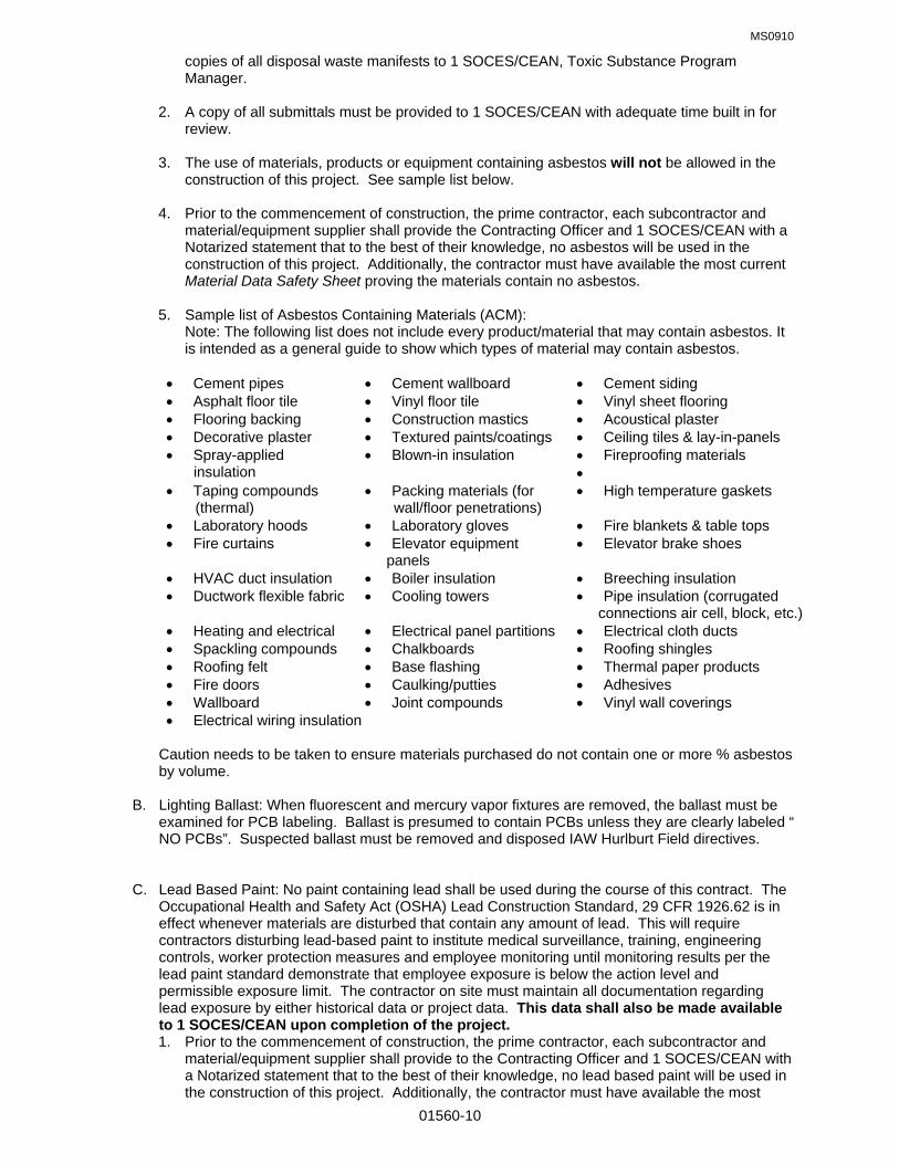
MS0910
01560-10
copies of all disposal waste manifests to 1 SOCES/CEAN, Toxic Substance Program Manager.
2. A copy of all submittals must be provided to 1 SOCES/CEAN with adequate time built in for review.
3. The use of materials, products or equipment containing asbestos will not be allowed in the construction of this project. See sample list below.
4. Prior to the commencement of construction, the prime contractor, each subcontractor and material/equipment supplier shall provide the Contracting Officer and 1 SOCES/CEAN with a Notarized statement that to the best of their knowledge, no asbestos will be used in the construction of this project. Additionally, the contractor must have available the most current Material Data Safety Sheet proving the materials contain no asbestos.
5. Sample list of Asbestos Containing Materials (ACM): Note: The following list does not include every product/material that may contain asbestos. It is intended as a general guide to show which types of material may contain asbestos.
Cement pipes Cement wallboard Cement siding Asphalt floor tile Vinyl floor tile Vinyl sheet flooring Flooring backing Construction mastics Acoustical plaster Decorative plaster Textured paints/coatings Ceiling tiles & lay-in-panels Spray-applied
insulation Blown-in insulation Fireproofing materials
Taping compounds (thermal)
Packing materials (for wall/floor penetrations)
High temperature gaskets
Laboratory hoods Laboratory gloves Fire blankets & table tops Fire curtains Elevator equipment
panels Elevator brake shoes
HVAC duct insulation Boiler insulation Breeching insulation Ductwork flexible fabric Cooling towers Pipe insulation (corrugated
connections air cell, block, etc.) Heating and electrical Electrical panel partitions Electrical cloth ducts Spackling compounds Chalkboards Roofing shingles Roofing felt Base flashing Thermal paper products Fire doors Caulking/putties Adhesives Wallboard Joint compounds Vinyl wall coverings Electrical wiring insulation
Caution needs to be taken to ensure materials purchased do not contain one or more % asbestos by volume.
B. Lighting Ballast: When fluorescent and mercury vapor fixtures are removed, the ballast must be examined for PCB labeling. Ballast is presumed to contain PCBs unless they are clearly labeled “ NO PCBs”. Suspected ballast must be removed and disposed IAW Hurlburt Field directives. C. Lead Based Paint: No paint containing lead shall be used during the course of this contract. The Occupational Health and Safety Act (OSHA) Lead Construction Standard, 29 CFR 1926.62 is in effect whenever materials are disturbed that contain any amount of lead. This will require contractors disturbing lead-based paint to institute medical surveillance, training, engineering controls, worker protection measures and employee monitoring until monitoring results per the lead paint standard demonstrate that employee exposure is below the action level and permissible exposure limit. The contractor on site must maintain all documentation regarding lead exposure by either historical data or project data. This data shall also be made available to 1 SOCES/CEAN upon completion of the project.
1. Prior to the commencement of construction, the prime contractor, each subcontractor and material/equipment supplier shall provide to the Contracting Officer and 1 SOCES/CEAN with a Notarized statement that to the best of their knowledge, no lead based paint will be used in the construction of this project. Additionally, the contractor must have available the most

MS0910
01560-11
current Material Data Safety Sheet proving that the paint does not have any lead content. If lead based paint has been identified, copies of surveys must be forwarded to 1 SOCES/CEAN, Toxic Substance Program Manager.
2. The contractor shall be responsible for collection and disposal of all lead paint chips and lead paint-contaminated materials, and for accumulation of these chips/materials on site. The contractor shall test the paint materials, provide containers for proper disposal, and transport any resulting hazardous waste to an appropriate hazardous waste accumulation area should it test positive as hazardous waste. All necessary accumulation, disposal activities and documentation shall be coordinated with the 1 SOCES/CEA flight.
3. A copy of contractor’s exposure assessment data shall be provided to 1 SOCES/CEAN.
4. Copies of all lead paint-related documentation generated from this project, including lead testing, air monitoring and hazardous waste manifests, shall be provided by the Contractor to the Contracting Officer. A copy shall be forwarded to 1 SOCES/CEAN within 10 working days of task completion.
5. On Military Family Housing Projects, there shall be in-depth coordination with the 1SOCES/CEAC flight to allow for resident notification and necessary arrangements.
The contractor is strongly encouraged to coordinate closely with 1SOCES/CEAN for any required guidance on this critical issue. 6. Contractors performing renovation, repair and painting projects that disturb lead-based paint
in homes, child care facilities, and schools built before 1978, must be certified and must follow specific work practices to prevent lead contamination (40 CFR Part 745). Upon completion of any lead base paint abatement, the contractor will provide copies of all disposal waste manifests to 1 SOCES/CEAN, Toxic Substance Program Manager.
3.14 SPILL PREVENTION:
A. The contractor is required to familiarize their employees with spill procedures, fire suppression systems and Material Safety Data Sheets for all materials used and/or stored at the project site. In the event of an oil, fuel or chemical spill, the contractor shall immediately notify the Hurlburt Field Fire Department by calling 911. The contractor shall also notify the Contracting Officer (CO) and provide a detailed, written spill report to 1 SOCES/CEAN within 24 hours describing the events of the release. Costs incurred from contractor related spills are the responsibility of the contractor. The contractor shall reimburse any government cost associated with spill response and clean-up.
B. The contractor shall provide and maintain spill containment equipment, sufficient in both type and
quantity, at all sites involving the storage, use or handling of hazardous waste and hazardous materials. The type of spill equipment and quantity required will be identified in the contractor’s site specific contingency plan. Equipment and materials must be adequate to contain any release and secondary containment must be in use as required.
C. If the contractor is required to stockpile contaminated soil for testing prior to disposal, the CO will inform the contractor of the stockpile location after consultation with 1 SOCES/CEAN.
D. Contractor vehicle and heavy equipment maintenance (including oil changing, lubrication, and
vehicle washing) is not authorized on base.
E. All fuel, oil, and chemical spills that occur on Hurlburt Field (regardless of amount) must be immediately reported to the base Fire Department by calling 911.
3.15 LABORATORY REQUIREMENTS A. The contractor shall as required use a laboratory capable of performing all analysis required to determine Resource Conservation and Recovery Act (RCRA) characteristics such as, but not limited to, Toxicity Characteristic Leaching Procedure (TCLP) metals, TCLP volatile and semi-

MS0910
01560-12
volatile organic, flashpoint, reactivity, and pH. The laboratory shall also be capable of performing any analysis required to determine the applicability of the used oil criteria detailed in 40 CFR, Part 279. The contractor shall ensure that all analytical work is performed IAW the methods and procedures, including QA/QC requirements, detailed in EPA SW-8467. The analytical laboratory shall be capable of providing accurate, complete data within eight (8) working days. Field analysis and portable instrumentation shall not be used to fulfill laboratory requirements. The contractor shall retain all data on file for a minimum of three years and keep it readily available for inspection by any authorized agency, including 1 SOCES/CEA Asset Management Flight. Chain- of-custody documents shall be included with these records. At the end of the contract, all of these data files may be transferred to 1 SOCES/CEA. 3.16 POST CONSTRUCTION CLEANUP A. The Contractor shall clean up all areas affected by construction and restore them back to their original condition to include landscaping, planting of trees, grass, and shrubs damaged by construction; and raking and disposal of debris such as roof shingles, paper, nails, glass, sheet metal, bricks, and waste concrete. Backfilled areas shall be compacted properly and replanted with grass.
3.17 INSTALLATION RESTORATION PROGRAM (IRP) A. Contractors and Project Managers (PM) planning projects on Hurlburt Field should be aware of the potential to encounter soil/groundwater contamination throughout many areas of the base. The following guidance has been developed to assist in the planning, designing and construction of projects in possibly contaminated areas (IRP sites). The first set of guidance is the most stringent and involves projects planned in an area that has known contamination and regulatory Land Use Controls. The second set of guidance applies to projects planned near a known IRP site with suspected contamination. The last set of guidance is general and applies to any areas of the base where contamination has not been confirmed. It is imperative that planners, designers and contractors involve 1 SOCES/CEA early and often in the planning, designing, and construction process to minimize the impact that contaminated soils/groundwater may have on their project. B. Projects located on a site with known soil and/or groundwater contamination with land use controls:
1. There are land use controls on this area imposed by an environmental regulatory agency designed to protect public health.
2. Project Manager should investigate and plan to ensure all monitor wells/cleanup systems are avoided.
3. Project Manager should submit detailed work plans to 1 SOCES/CEA early in planning stages so 1 SOCES/CEA can obtain concurrence from the regulatory agencies on project details.
4. Project Manager should educate workers on potential to encounter contamination and also should ensure workers are adequately protected with personal protective equipment.
5. If unusual soil or groundwater color/odor is encountered during subsurface work, contact 1 SOCES/CEA.
C. Projects located near a site with known or suspected soil and/or groundwater contamination without land use controls:
1. If unusual soil or groundwater color/odor is encountered during subsurface work, contact 1 SOCES/CEA.
2. Project Manager should investigate and plan to ensure all monitor wells/cleanup systems are avoided.
3. Project Manager should educate workers on potential to encounter contamination and also should ensure workers are adequately protected with personal protective equipment.
D. Sites without land use controls and not in close proximity to known contamination or IRP site:
1. If unusual soil or groundwater color/odor is encountered during subsurface work, contact

MS0910
01560-13
1 SOCES/CEA.
2. Project Manager should educate workers on potential to encounter contamination and also should ensure workers are adequately protected with personal protective equipment.
E. Be aware that the regulatory agency can halt the project for long periods of time due to the discovery of contamination. 1 SOCES/CEA is committed to expediting projects with IRP compliance related issues.
3.15 STORAGE TANKS A. 1 SOCES/CEA must approve the use of fuel storage tanks on base, and the contractor must ensure adequate spill containment (spill kits) for any tanks approved for use on Hurlburt Field. The contractor must have written spill procedures for tanks and heavy equipment that they use on base. Temporary gasoline storage is NOT permitted on base.
B. POL/Storage Tanks: Storage tanks and POL can be a source of contamination if not managed
appropriately. Contractor personnel obtaining fuels from Storage Tanks agree to follow all 62-762 FAC and the following list of Air Force Technical Order’s to ensure compliance: 37-1-1, 37A-1-101, 42B-1-1, 42B-1-1S-2, 42B-1-16, 42B-1-22, 42B-1-23, and 42C-1-12.
C. Contractor must contact 1SOCES/CEA for a copy of Hurlburt Field’s Spill Prevention Control and
Countermeasure Plan (SPCC), if storage tanks us is approved. A number of Federal and State agencies have regulations pertaining to pollution prevention and emergency response requirements of oil and hazardous storage and transfer facilities. The Hurlburt Field SPCC Plan has been developed to address the issues of spill prevention, discharge containment / cleanup, and emergency response actions.
END OF SECTION

MS0109
01580-1
SECTION 01580 PROJECT IDENTIFICATION SIGN PART 1 GENERAL 1.01 RELATED SPECIFICATION SECTIONS: A. Section 01000 – GENERAL REQUIREMENTS 1.02 SECTION INCLUDES: A. Project Identification Sign. 1.03 QUALITY ASSURANCE: A. Design sign and structure in accordance with drawing shown on page 2 of this specification. B. Use experienced professional sign painter. C. Finishes shall be adequate to withstand weathering, fading, and chipping, for duration of construction. PART 2 PRODUCTS 2.01 SIGN MATERIALS: A. Structure and Framing: New, pressure-treated 4 x 4 x 12' support posts. B. Sign Surfaces: Exterior grade plywood, A-C, 1/2" thick, 4'-0" x 8'-0". C. Paint and Primers: Exterior professional quality, high-gloss alkyd enamel. D. Lettering: Exterior quality paint as per above, or pre-cut vinyl self-adhesive products, in accordance with
attached drawing. PART 3 EXECUTION 3.01 INSTALLATION: A. Install project identification sign within 15 days after Notice to Proceed. 1. Install at a location of high public visibility adjacent to main entrance to site. 2. Erect sign surface plumb and level. Anchor securely. 3. Paint exposed surfaces of sign, supports, and framing. 3.02 MAINTENANCE: A. Maintain sign and supports clean. B. Repair deterioration and damage. 3.03 REMOVAL: A. Remove signs, framing, supports, and foundations at completion of project and restore the area.

MS0109
01580-2
1 S
PE
CIA
L O
PE
RA
TIO
NS
CIV
IL E
NG
INE
ER
SQ
UA
DR
ON
INU
.S.
AIR
FO
RC
E P
RO
JEC
T
PA
RT
NE
RS
HIP
WIT
H 1
SP
EC
IAL
OP
S C
ON
TR
AC
TIN
G S
QU
AD
RO
N
PR
OJE
CT
TIT
LE
PR
OJE
CT
TIT
LE
GE
NE
RA
L C
ON
TR
AC
TO
RN
AM
E O
F C
ON
TR
AC
TO
RA
RC
HIT
EC
T-E
NG
INE
ER
1 S
OC
ES
/CE
CC
8'-0
"
4'-0"
12
3 4 5
67
A BC
D E F G H
1.
US
E 1
/2"
GR
AD
E A
-C E
XT
ER
IOR
PLY
WO
OD
2. P
AIN
T W
ITH
EX
TE
RIO
R G
LOS
S E
NA
ME
L:
a.
1 C
OA
T P
RIM
ER
b. 2
CO
AT
S C
OLO
R #
2012
2, F
ED
. ST
AN
DA
RD
595
B
c.
WH
ITE
LE
TT
ER
S3.
MO
UN
T S
EC
UR
EL
Y O
N P
RE
SS
UR
E T
RE
AT
ED
4x4
s,
WIT
H B
OT
TO
M 4
' FR
OM
GR
AD
E4.
RE
MO
VE
SIG
N A
FT
ER
CO
MP
LET
ION
OF
CO
NS
TR
UC
TIO
N
SP
AC
EA B C D E F G H
1" 6" 5"1"6" 3"
HE
IGH
T5" 1"
2"3
2"6 7
2"
4 55" 5"
HE
IGH
TLI
NE
1 22" 2"
3/16
"
3/16
"3/
16"
1/2"
1/2"
ST
RO
KE
3/16
"3/
16"
LET
TE
R
END OF SECTION

MS0109
01600-1
SECTION 01600 MATERIAL AND EQUIPMENT PART 1 GENERAL 1.01 RELATED SPECIFICATION SECTIONS: A. Section 01000 – GENERAL REQUIREMENTS 1.02 PRODUCTS A. Products means new material, machinery, components, equipment, fixtures and systems forming the
Work. Does not include machinery and equipment used for preparation, fabrication, conveying and erection of the work. Products may also include existing materials or components required for reuse.
B. Do not use materials and equipment removed from existing premises except as specifically permitted by
the Contract Documents and approved by the Contracting Officer. C. Provide interchangeable components of the same manufacturer for similar components. 1.03 TRANSPORTATION AND HANDLING: A. Transport and handle products in accordance with manufacturer's instructions. B. Promptly inspect shipments to assure that products comply with requirements, quantities are correct, and
products are undamaged. C. Provide equipment and personnel to handle products by methods to prevent soiling, disfigurement or
damage. 1.04 STORAGE AND PROTECTION: A. Store and protect products in accordance with manufacturer's instructions, with seals and labels intact
and legible. Store sensitive products in weathertight, climate controlled enclosures.
B. For exterior storage of fabricated products, place on sloped supports above ground. C. Cover products subject to deterioration with impervious sheet covering. Provide ventilation to avoid
condensation. D. Store loose granular materials on solid flat surfaces in a well-drained area. Prevent mixing with foreign
matter.
E. Provide equipment and personnel to store products by methods to prevent soiling, disfigurement or damage.
F. Arrange storage of products to permit access for inspection. Periodically inspect to assure products are
undamaged and are maintained under specified conditions. 1.05 PRODUCT OPTIONS: A. Products Specified by Reference Standards or by Description Only: Any product meeting those
standards or description. B. Products Specified by Naming One or More Manufacturers with a Provision for substitutions: Submit a
request for substitution for any manufacturer not named. 1.06 SUBSTITUTIONS: A. Substitutions will be considered under provisions of Section 01000. B. Document each request with complete data substantiating compliance of proposed substitution with
Contract Documents. C. A request constitutes a representation that the contractor:

MS0109
01600-2
1. Has investigated proposed product and determined that it meets or exceeds the quality level of the specified product.
2. Will provide the same warranty for the substitution as for the specified product. 3. Will coordinate installation and make changes to other work which may be required for the work to be
complete with no additional cost to the Government. 4. Waives claims for additional costs or time extension which may subsequently become apparent.
5. Will reimburse Government for redesign services associated with the request. D. Substitutions will not be considered when they are indicated or implied on shop drawing or
product data submittals without separate written request, or when acceptance will require revision to the Contract Documents.
E. Substitution Submittal Procedure: 1. Submit four (4) copies of request for substitution for consideration. Limit each request to one
proposed substitution. 2. Submit shop Drawings, product data, and certified test results attesting to the proposed product
equivalence. 3. Submit one (1) copy of the material specification, product data, and a physical sample of each finish
material (carpet, rubber/vinyl base, wall covering, vinyl composition tile, ceramic tile, acoustical ceiling, etc.) of the specified material for which a substitution is proposed. This information will be used to compare the proposed substitution to the specified material to assure compliance with the contract requirements.
PART 2 PRODUCTS (NOT USED) PART 3 EXECUTION (NOT USED) END OF SECTION

MS0109
01650-1
SECTION 01650 STARTING OF SYSTEMS PART l GENERAL 1.01 RELATED SPECIFICATION SECTIONS: A. Section 01000 – GENERAL REQUIREMENTS 1.02 STARTING SYSTEMS A. Coordinate schedule for start-up of various equipment and systems. B. Notify project inspector 7 days prior to start-up of each item. C. Verify that each piece of equipment or system has been checked for proper lubrication, drive rotation, belt
tension, control sequence, or other conditions, which may cause damage. D. Verify that tests, meter readings and specified electrical characteristics agree with those required by the
equipment or system manufacturer. E. Verify wiring and support components for equipment are complete and tested. F. Execute start-up under supervision of responsible manufacturer's representative if required by manufacturer or contractors' personnel in accordance with manufacturers' instructions. G. When specified in individual Specification Sections, require manufacturer to provide authorized representative to be present at site to inspect, check and approve equipment or system installation prior to start-up, and to supervise placing equipment or system in operation. H. Submit a written report in accordance with applicable Section of Specifications that equipment or system has been properly installed in accordance with manufacturer's installation instructions and is functioning
correctly. 1.03 DEMONSTRATION AND INSTRUCTIONS A. Demonstrate operation and maintenance of products to Government personnel 7 days prior to date of
final inspection. B. Utilize operation and maintenance manuals as basis for demonstration. Review contents of manual with
government personnel in detail to explain all aspects of operation and maintenance. C. Demonstrate start-up, operation, control, adjustment, trouble-shooting, servicing, maintenance, and shutdown of each item of equipment at scheduled times, at equipment designated location. D. Prepare and insert additional data in operations and maintenance manuals when need for additional data
becomes apparent during instruction. 1.04 TESTING, ADJUSTING AND BALANCING A. Contractor will appoint, employ and pay for services of an independent firm to perform testing, adjusting
and balancing. B. Reports will be submitted by the independent firm to the Contracting Officer indicating observations and
results of tests and indicating compliance or non-compliance with specified requirements and with the requirements of the Contract Documents. PART 2 PRODUCTS (NOT USED); PART 3 EXECUTION (NOT USED) END OF SECTION

MS0510
01700-1
SECTION 01700 CONTRACT CLOSEOUT PART 1 GENERAL 1.01 RELATED SPECIFICATION SECTIONS: A. Section 01000 – GENERAL REQUIREMENTS 1.02 SECTION INCLUDES A. Closeout procedures. B. Final cleaning. C. Adjusting. D. Project record documents. E. Operation and maintenance data. F. Spare parts and maintenance products. G. Warranties. H. Maintenance service. 1.03 CLOSEOUT PROCEDURES A. Submit written certification that Contract Documents have been reviewed, Work has been inspected,
and that Work is complete in accordance with Contract Documents and ready for final inspection. B. Upon completion of final inspection, correct punch list items to the satisfaction of the government, and
submit all closeout documents, the Government shall take beneficial occupancy of building (BOD). All warranties will start when government takes BOD.
C. Provide closeout submittals to Government as required by contract documents. Complete and
submit attached closeout checklist. 1.04 FINAL CLEANING A. Execute final cleaning prior to final inspection. B. Clean interior and exterior glass, surfaces exposed to view; remove temporary labels, stains and
foreign substances, polish transparent and glossy surfaces, vacuum and remove any stains from carpeted and soft surfaces.
C. Clean equipment and fixtures to a sanitary condition with cleaning materials appropriate to the
surface and material being cleaned. D. Replace filters of operating equipment. E. Clean debris from roofs, gutters, downspouts, and drainage systems. F. Clean site; sweep paved areas, rake clean landscaped surfaces. G. Remove waste and surplus materials, rubbish, and construction facilities from the site. 1.05 ADJUSTING A. Adjust operating products and equipment to ensure smooth and unhindered operation. 1.06 PROJECT RECORD DOCUMENTS A. Maintain on site one set of the following record documents; record actual revisions to the Work:

MS0510
01700-2
1. Drawings. 2. Specifications. 3. Addenda. 4. Change Orders and other modifications to the Contract. 5. Reviewed Shop Drawings, Product Data, and Samples. 6. Manufacturer's instruction for assembly, installation, and adjusting. B. Ensure entries are complete and accurate, enabling future reference by Owner. C. Store record documents separate from documents used for construction. Do not put extraneous
marks or other information on these documents. Maintain documents in good, clean condition free from tears or damage.
D. Record information concurrent with construction progress. E. Specifications: Legibly mark and record at each Product section description of actual Products
installed, including the following: 1. Manufacturer's name and product model and number. 2. Product substitutions or alternates utilized. 3. Changes made by Addenda and modifications. F. Record Drawings and Shop Drawings: Legibly mark each construction change on the respective
drawing sheet or sheets to record actual construction including: 1. Addenda issued prior to receipt of bid or proposal. 2. Change orders issued during the construction phase. 3. Measured depths of foundations in relation to finish floor datum. 4. Measured horizontal and vertical locations of underground utilities and appurtenances referenced
to permanent surface improvements. 5. Measured locations of external and internal utilities, and appurtenances concealed in
construction, referenced to visible and accessible features of the Work. 6. Field changes of dimension and detail. 7. Details not on original Contract drawings. 8. Field changes related to materials. G. Prior to final inspection the contractor shall: 1. Submit original record documents to Contracting Officer. Contractor is advised to have a
reproduced copy of the original record documents made for their records. 2. Obtain Disc copies of the contract drawings in current version of AUTOCAD used by
1SOCES/CEP. Verify with the project inspector. Correct drawing files (sheets) to reflect all as-built conditions based on the changes made as per item F. above. Add the words “AS BUILT” to the revision block of each sheet title block, the date the drawings were changed and the initials of the person making the change.
3. Submit one set of prints of the corrected contract drawing files to allow Base Civil engineer to verify accuracy of the corrected drawings against the record documents.
4. Upon review and approval of the corrected contract drawing files, provide disc copies to the government for their records.
5. Completed Construction Data Worksheet. See Section 01000, paragraph 1.07 6. Project Closeout Check List. See end of section. 7. See Section 01000, paragraph 1.15.C referencing 3% payment retention until receipt and
approval of Closeout Documents. 8. See Section 01010, paragraph 3.05. referencing location of buildings, etc. to be submitted with As-Built documents. H. Upon acceptance of the building, project record documents and the “As Built” drawings by the
Contracting Officer and the Base Civil Engineer, final payment will be made to the contractor 1.07 OPERATION AND MAINTENANCE DATA A. Submit data bound in 8-1/2 x 11 inch text pages, three ring binders with durable plastic covers.
General contractor shall assemble all O & M data required on project and submit as a single submittal

MS0510
01700-3
B. Prepare binder cover with printed title "OPERATION AND MAINTENANCE INSTRUCTIONS", title of
project, and subject matter of binder when multiple binders are required. C. Internally subdivide the binder contents with permanent page dividers, logically organized as
described below; with tab titling clearly printed under reinforced laminated plastic tabs. D. Contents: Prepare a Table of Contents for each volume, with each Product or system description
identified, typed on white paper, in three parts as follows: 1. Part 1: Directory, listing names, addresses, and telephone numbers of Contractor,
Subcontractors, and major equipment suppliers. 2. Part 2: Operation and maintenance instructions, arranged by system and subdivided by
specification section. For each category, identify names, addresses, and telephone numbers of Subcontractors and suppliers. Identify the following:
a. Significant design criteria. b. List of equipment. c. Parts list for each component. d. Operating instructions. e. Maintenance instructions for equipment and systems. f. Maintenance instructions for special finishes, including recommended cleaning methods and
materials, and special precautions identifying detrimental agents. 3. Part 3: Project documents and certificates, including the following: a. Shop drawings and product data. b. Air and water balance reports. c. Certificates. d. Photocopies of manufacturer's warranties. E. Submit 1 draft copy of completed volumes 5 days prior to final inspection. This copy will be reviewed
and returned after final inspection, with comments. Revise content of all document sets as required prior to final submission.
F. Submit two sets of revised final volumes, within 10 days after final inspection. 1.08 SPARE PARTS AND MAINTENANCE PRODUCTS A. Provide spare parts, maintenance, and extra products in quantities specified in individual
specification sections. B. Deliver to Project site and place in location as directed; obtain receipt prior to final payment. 1.09 CONTRACTOR/SUBCONTRACTOR WARRANTIES A. Provide triplicate notarized copies. B. Execute and assemble transferable warranty documents from Subcontractors, suppliers, and
manufacturers. C. Submit prior to final Application for Payment. D. All warranties shall be submitted within 10 days from BOD with warranty start dates printed on
warranties. 1.10 MAINTENANCE SERVICE A. Furnish service and maintenance of components where indicated in specification sections during the
warranty period. B. Examine system components at a frequency consistent with reliable operation. Clean, adjust, and
lubricate as required. C. Include systematic examination, adjustment, and lubrication of components. Repair or replace parts
whenever required. Use parts produced by the manufacturer of the original component. D. Maintenance service shall not be assigned or transferred to any agent or Subcontractor without prior
written consent of the Government

MS0510
01700-4
PART 2 PRODUCTS (NOT USED); PART 3 EXECUTION (NOT USED)
END OF SECTION

MS0510
01700-5
PROJECT CLOSEOUT CHECK LIST PROJECT # AND TITLE: ______________________________________________________________ CONTRACTOR: ______________________________________________________________________ CONTRACTOR (mark n/a next to those items that are not applicable for this project) ________ TEST AND BALANCE REPORT SUBMITTED, APPROVED AND INCLUDED IN THE O&M
MANUALS. REPORT SHALL BE SUBMITTED PRIOR TO FINAL INSPECTION. ________ HAVE O&M MANUALS BEEN SUBMITTED AND APPROVED. MANUALS ARE TO BE
ASSEMBLED BY THE GENERAL CONTRACTOR AND SUBMITTED UNDER A SINGLE COVER PER SECTION 01700. (SEE ATTACHED LIST). MANUALS SHALL BE SUBMITTED PRIOR TO FINAL INSPECTION.
________ PUNCH LIST COMPLETED. ________ HAS MECHANICAL AND ELECTRICAL IDENTIFICATION BEEN COMPLETED. ________ HAS COMPLETED CONSTRUCTION DATA WORKSHEET. ________ HAVE THE RECORD DOCUMENTS AND AS-BUILT DRAWINGS BEEN SUBMITTED AND
APPROVED PER SECTION 01700. ________ HAS THE DDC PROGRAMMING FOR THE HOST COMPUTER BEEN DOWN LOADED TO
THE CONTROLS SHOP. ________ HAS FINAL CLEANING BEEN COMPLETED. ________ HAVE SPARE PARTS BEEN TURNED OVER TO THE GOVERNMENT. (SEE ATTACHED
LIST) ________ HAVE WARRANTIES BEEN SUBMITTED AND APPROVED. (SEE ATTACHED LIST) ________ HAVE DIGITAL RECORD DRAWINGS BEEN SUBMITTED (SECTION 02811 LANDSCAPE
IRRIGATION AND 15330 FIRE SUPPRESSION) ________ HAS ALL REQUIRED TRAINING BEEN ACCOMPLISHED. (SEE ATTACHED LIST) ________ HAS ALL REQUIRED TESTING BEEN ACCOMPLISHED. (SEE ATTACHED LIST). ________ HAVE ITEMS TO BE TURNED OVER TO GOVERNMENT BEEN TURNED OVER. ________ HAVE REPLACEMENT TREES BEEN PLANTED IN AUTHORIZED LOCATION ________ IS CONSTRUCTION SITE STABLE, NO EROSION ________ HAS ALL CONTRACTOR HAZMAT BEEN REMOVED FROM PROJECT SITE ________ HAS CONTRACTOR SUBMITTED THE TOTAL HAZARDOUS MATERIALS USED DURING
CONTRACT ________ HAS CONTRACTOR PROVIDED WITNESSED AND NOTARIZED STATEMENT THAT
PROJECT WAS CONSTRUCTED IN ACCORDANCE WITH THE CONTRACT DOCUMENTS INCLUDING ALL CHANGES MADE DURING THE CONSTRUCTION PHASE.
________ WARRANTY FORM

MS0510
01700-6
PROJECT # AND TITLE: ______________________________________________________________ CONTRACTOR: ______________________________________________________________________ INSPECTORS ________ HAVE THE ABOVE ITEMS BEEN COMPLETED BY THE CONTRACTOR. ________ HAS 100% COMPLETION LETTER AND BLUE BOOKS BEEN SENT TO CONTRACTING. ________ HAS FINAL PAYMENT BEEN APPROVED. ________ HAS WARRANTY DATE BEEN ESTABLISHED. DATE:__________________ ________ HAVE RECORD DRAWINGS AND ORGINALS BEEN TURNED OVER TO DRAFTING FOR
DOING AS-BUILTS AND FILING. ________ HAVE O&M MANUALS BEEN TURNED OVER THE SHOPS. ________ HAS 1354 BEEN COMPLETED AND TURNED OVER TO REAL PROPERTY ALONG WITH
INPECTORS AND ENGINEERS FOLDERS. ** ________ HAS CONTRACTOR’S WRITTEN, WITNESSED AND NOTARIZED STATEMENT RE
COMPLETION OF THE PROJECT BEEN TURNED OVER TO THE GOVERNMENT. SEE ECTION 01000 GENERAL REQUIREMENTS, PARAGRAPH 1.15. ________ HAS PERFORMANCE EVALUATIONS BEEN RECEIVED, COMPLETED AND RETURNED. ________ HAVE ASBESTOS RECORDS BEEN RECEIVED FROM CONTRACTOR AND TURNED OVER
TO CEV. ________ HAVE ENVIRONMENTAL PERMIT CERTIFICATIONS ISSUED FOR POTABLE WATER,
SANITARY SEWER, OR STORMWATER BEEN CLOSED OUT. ** 1354 SHOULD BE COMPLETED PRIOR TO TURNING IN O&M MANUALS, AS-BUILTS DRAWINGS AND
BLUE BOOKS.

MS0510
01700-7
PROJECT # AND TITLE: ______________________________________________________________ CONTRACTOR: ______________________________________________________________________ SPARE PARTS ________ Section 09511 ceiling tile ________ Section 09650 flooring base ________ Section 12512 blinds ________ Section 15330 fire sup. heads ________ Section 15623 filters ________ Section 15855 filters ________ Section 16470 keys ________ Section 16495 keys ________ Section 16530 lamps ________ Section 16730 intrusion detection O&M MANUALS ________ Section 02811 irrigation sys ________ Section 09311 ceramic tile ________ Section 09688 carpet ________ Section 10522 fire extinguishers ________ Section 11306 lift stations ________ Section 15330 fire suppr. ________ Section 15410 plumbing piping ________ Section 15430 plumbing spec. ________ Section 15440 plumbing fixtures ________ Section 15450 pluming eq. ________ Section 15515 hydronic spec. ________ Section 15540 pumps ________ Section 15558 boilers ________ Section 15623 furn. & a/c ________ Section 15625 unit heaters ________ Section 15682 chillers ________ Section 15855 air handlers ________ Section 15870 ventilators ________ Section 15930 terminal units ________ Section 15975 controls ________ Section 16321 transformers ________ Section 16495 transfer switch ________ Section 16496 bypass switch ________ Section 16510 interior lights ________ Section 16530 site lighting ________ Section 16615 emer. power ________ Section 16622 generators ________ Section 16721 fire alarm ________ Section 16730 intrusion detection WARRANTIES ________ Section 02281 termite control ________ Section 07410 metal roofing ________ Section 07900 joint sealers ________ Section 07550 bituminous roofing ________ Section 08210 wood doors ________ Section 13121 metal bldg. roofing ________ Section 13121 metal bldgs ________ Section 15440 water cooler ________ Section 15450 water heater ________ Section 15558 boiler ________ Section 15623 compressor ________ Section 15625 unit heater ________ Section 15682 chiller ________ Section 15930 terminal units ________ Section 16531 ballfield lighting ________ Section 16615 emer. Power supply ________ Section 16622 generator TRAINING ________ Section 15558 boilers ________ Section 15682 chillers ________ Section 15975 controls ________ Section 16622 generators ________ Section 16721 alarm system
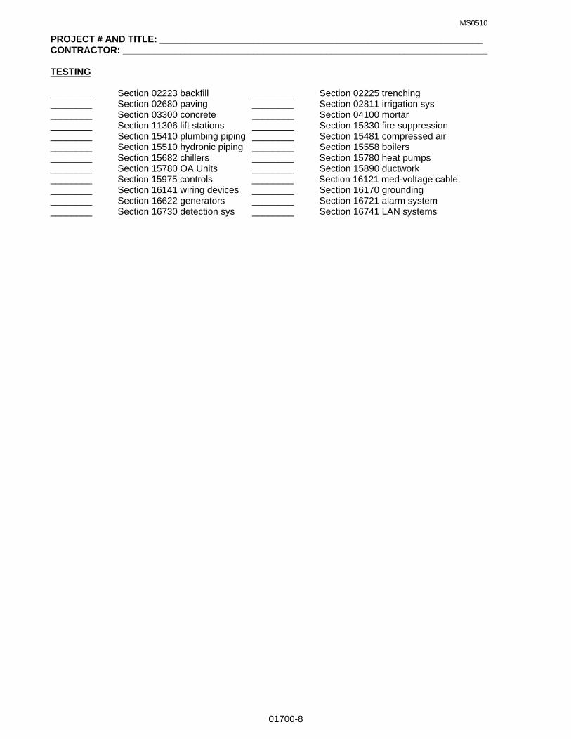
MS0510
01700-8
PROJECT # AND TITLE: ______________________________________________________________ CONTRACTOR: ______________________________________________________________________ TESTING ________ Section 02223 backfill ________ Section 02225 trenching ________ Section 02680 paving ________ Section 02811 irrigation sys ________ Section 03300 concrete ________ Section 04100 mortar ________ Section 11306 lift stations ________ Section 15330 fire suppression ________ Section 15410 plumbing piping ________ Section 15481 compressed air ________ Section 15510 hydronic piping ________ Section 15558 boilers ________ Section 15682 chillers ________ Section 15780 heat pumps ________ Section 15780 OA Units ________ Section 15890 ductwork ________ Section 15975 controls ________ Section 16121 med-voltage cable ________ Section 16141 wiring devices ________ Section 16170 grounding ________ Section 16622 generators ________ Section 16721 alarm system ________ Section 16730 detection sys ________ Section 16741 LAN systems

MS0510
01700-9
P R O J E C T W A R R A N T Y F O R M
BUILDING NUMBER & STREET ADDRESS: ____________________________________________________
PROJECT NUMBER & TITLE: ____________________________________________________
CONTRACT NUMBER: _____________________________________________________________________
PROJECT MANAGER & PHONE NO: _______________________________________________
CONTRACT SPECIALIST & PHONE NO. _______________________________________________________
DATE OF GOVERNMENT ACCEPTANCE: ______________________________________________________
GENERAL 0NE YEAR WARRANTY EXPIRATION DATE: __________________________________________
ONE YEAR WARRANTY INPSECTION DATE (30 days prior to expiration)___________________________
BRIEF DESCRIPTION OF WORK: ____________________________________________________________
_________________________________________________________________________________________
_________________________________________________________________________________________
_________________________________________________________________________________________
_________________________________________________________________________________________
PRIME KTR, PHONE NO. & FAX NO. __________________________________________________________
HVAC SUBKTR, PHONE & FAX NO. __________________________________________________________
PLUMBING SUBKTR, PHONE & FAX NOS. _____________________________________________________
ELECTRICAL SUBKTR. PHONE & FAX NO'S ___________________________________________________
E X T E N D E D W A R R A N T I E S
SPEC. ITEM & WARRANTY - RESPONSIBLE PARTY (IES)
02281 Termite Treatment, 5 yrs, Prime ktr & installer
02811 Irrigation System, 2 yr, Prime ktr & subktr
04300 Masonry, 2 yr, Prime ktr & subktr
07410 Preformed Metal Roofing, general, 2 yr Prime ktr & subktr
Panel finish, 20 year, Manufacturer
Leaking, 20 yr, Manufacturer
07550 Modified Bitumen Roofing, 10 yr, Manufacturer
07660 Sheet Metal Flashing & Trim, finish 20 yr, Manufacturer
08330 Overhead Rolling Doors, one year plus warranty, Manufacturer
13121 Pre-Engineered Building Systems, general, 2 yr, Prime ktr & installer
Siding finish, 5 yr, Manufacturer
Panel finish, 20 yr, Manufacturer
Leaking, 20 yr, Manufacturer
15440 Plumbing, water cooler compressor, 5 yr, Manufacturer
15450 Plumbing, water heater tank, 6 yr, Manufacturer
15481 Compressed Air Systems, air compressor, 5 yr, Manufacturer
15558 Finned Water Tube Boilers, boiler heat exchanger, 5 yr, Manufacturer
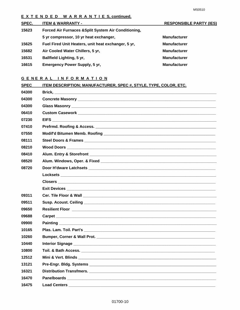
MS0510
01700-10
E X T E N D E D W A R R A N T I E S, continued.
SPEC. ITEM & WARRANTY - RESPONSIBLE PARTY (IES)
15623 Forced Air Furnaces &Split System Air Conditioning,
5 yr compressor, 10 yr heat exchanger, Manufacturer
15625 Fuel Fired Unit Heaters, unit heat exchanger, 5 yr, Manufacturer
15682 Air Cooled Water Chillers, 5 yr, Manufacturer
16531 Ballfield Lighting, 5 yr, Manufacturer
16615 Emergency Power Supply, 5 yr, Manufacturer
G E N E R A L I N F O R M A T I O N
SPEC ITEM DESCRIPTION; MANUFACTURER, SPEC #, STYLE, TYPE, COLOR, ETC.
04300 Brick, __________________________________________________________________________
04300 Concrete Masonry _______________________________________________________________
04300 Glass Masonry __________________________________________________________________
06410 Custom Casework _______________________________________________________________
07230 EIFS ___________________________________________________________________________
07410 Prefrmd. Roofing & Access. _______________________________________________________
07550 Modif'd Bitumen Memb. Roofing ___________________________________________________
08111 Steel Doors & Frames ____________________________________________________________
08210 Wood Doors ____________________________________________________________________
08410 Alum. Entry & Storefront __________________________________________________________
08520 Alum. Windows, Oper. & Fixed _____________________________________________________
08720 Door H'dware Latchsets __________________________________________________________
Locksets _______________________________________________________________________
Closers ________________________________________________________________________
Exit Devices ____________________________________________________________________
09311 Cer. Tile Floor & Wall _____________________________________________________________
09511 Susp. Acoust. Ceiling ____________________________________________________________
09650 Resilient Floor __________________________________________________________________
09688 Carpet _________________________________________________________________________
09900 Painting ________________________________________________________________________
10165 Plas. Lam. Toil. Part's ____________________________________________________________
10260 Bumper, Corner & Wall Prot. ______________________________________________________
10440 Interior Signage _________________________________________________________________
10800 Toil. & Bath Access. _____________________________________________________________
12512 Mini & Vert. Blinds _______________________________________________________________
13121 Pre-Engr. Bldg. Systems __________________________________________________________
16321 Distribution Transfmers. __________________________________________________________
16470 Panelboards ____________________________________________________________________
16475 Load Centers ___________________________________________________________________

MS0510
01700-11
G E N E R A L I N F O R M A T I O N, continued.
SPEC ITEM DESCRIPTION; MANUFACTURER, SPEC #, STYLE, TYPE, COLOR, ETC.
16495 Transfer Switch _________________________________________________________________
16496 By-pass Isolation Switch _________________________________________________________
16510 Interior Luminaires ______________________________________________________________
16530 Site Lighting ____________________________________________________________________
16622 Pkg. Engine Generator Syst. ______________________________________________________
16721 Fire Detect. & Alarm Syst. _________________________________________________________
16730 Intrusion Detect. Syst. ____________________________________________________________
I N S T R U C T I O N S
1. The prime contractor shall complete this form and provide it with the close out documentation.
2. Extended warranties; Provide name, phone and fax number for the responsible party (ies).
3. General Information; Provide name, phone and fax number, and pertinent information indicated for each item
listed.
4. It may not be required to use all of the items listed under Extended Warranties and General Information, in
the construction of this project. Should this occur, simply line through the item to indicate it was not used on
this project.
____________________________________ _____________________________________
Prime Contractor (See note below) Date
____________________________________ _____________________________________
Mailing Address City, State and Zip Code
____________________________________ _____________________________________
Phone Number Fax Number
____________________________________
E-mail Address
If prime contractor is a corporation, affix the corporate seal below and provide signature of responsible party who
can legally obligate the corporation.

MS0109
02070-1
SECTION 02070: SELECTIVE DEMOLITION PART 1 GENERAL
1.01 RELATED SPECIFICATION SECTION: A. Section 01000 – GENERAL REQUIREMENTS 1.02 SUMMARY A. Provide all demolition as required by the Contract Documents. 1. Demolish interior and exterior portions of structures including but not limited to, walls, partitions,
windows, doors, roofing, paving/curb/guttering, site furniture, shrubs, trees, interior finishes, etc., and associated components.
2. Demolish plumbing, mechanical, and electrical equipment and associated components 3. Demolished materials shall become the property of the Contractor unless otherwise noted on the
Drawings or in the Specifications. 4. Remove and dispose of demolished materials at a legally approved dumpsite off base. 5. Notify Contracting Officer prior to shut-off of existing utilities. Cap off utilities that are to remain in use. 6. Where fasteners, bolts, piping, wiring, ductwork and/or equipment that is/are to be removed are
attached to or pass through walls, floors, ceilings or roofs, the Contractor shall patch all holes or openings under 1(one) square foot in size to match adjacent construction. Patch holes or openings in fire rated walls as required to maintain fire rating.
7. Existing fire suppression systems, fire detection systems, and intrusion systems must remain active unless approved by the Contracting Officer and the responsible agency (Fire Department/Security Forces). Required deactivation of systems, or portions thereof, during demolition/construction must be requested and approved 72 hours in advance. Contractor will be responsible for protection of premises during periods of deactivation. If necessary, provide temporary protection or services.
1.03 SUBMITTALS
A. Submit for approval selective demolition schedule, including schedule and methods for capping and continuing utility service, and clearing & grubbing schedule.
1.04 QUALITY ASSURANCE
A. Comply with governing codes and regulations. Use experienced workmen. 1.05 PROJECT CONDITIONS
A. Government personnel will not occupy areas of Work during demolition. PART 2 PRODUCTS (Not Used) PART 3 EXECUTION 3.01 DEMOLITION A. Do not damage building elements and improvements indicated to remain. Items of salvage value and not
included on schedule of salvage items to be returned to Government may be removed from structure. Storage or sale of items at Project site is prohibited.
B. Do not close or obstruct streets, walks, drives or other occupied or used spaces or facilities without the
written permission of the Contracting Officer and the authorities having jurisdiction. Do not interrupt utilities serving occupied or used facilities without the written permission of the Contracting Officer and authorities having jurisdiction. If necessary, provide temporary utilities
C. Cease operations if public safety or remaining structures are endangered. Perform temporary corrective
measures until operations can be continued properly. Complete closure of Air Force roads will not be authorized.
END OF SECTION

MS0109
02110-1
SECTION 02110: SITE CLEARING & GRADING PART 1 GENERAL 1.01 RELATED SPECIFICATION SECTIONS: A. Section 01000 – GENERAL REQUIREMENTS 1.02 SECTION INCLUDES A. Remove surface debris. B. Clear site of plant life and grass. C. Remove trees and shrubs. D. Remove root system of trees and shrubs.
E. Topsoil excavation. F. Site Grading 1.03 REGULATORY REQUIREMENTS A. Conform to applicable regulations and local ordinances for disposal of debris off Base.
B. Coordinate clearing Work with utility companies. 1.04 QUALITY ASSURANCE
A. Use skilled workman who are thoroughly trained and experienced in the necessary crafts and who are completely familiar with particular requirements of the Project and methods needed to accomplish same.
B. Use equipment adequate in size, capacity and numbers to accomplish the Work in a timely manner. PART 2 PRODUCTS 2.01 MATERIALS
A. Fill Materials, See Section 02223, Backfilling. B. Weed Killer: Provide a dry, free-flowing, dust free chemical compound, soluble in water, capable of
inhibiting the growth of weeds and other undesirable vegetation and approved for use on base by governmental agencies having jurisdiction.
C. Topsoil: Use stockpiled topsoil or provide topsoil consisting of friable, fertile soil of loamy character,
containing an amount of organic material normal to the region. Topsoil shall be capable of sustaining healthy plant life and be reasonably free from subsoils, roots, heavy or stiff clay, stones larger than 2” in greatest dimension, weeds, sticks, brush and other deleterious material.
PART 3 EXECUTION 3.01 PREPARATION
A. Verify that existing plant life designated to remain is tagged or identified. B. Examine the areas and conditions under which Work of this Section will be performed. Correct conditions
detrimental to the timely and proper completion of the Work. Do not proceed until unsatisfactory conditions are corrected.
3.02 PROTECTION
A. Protection of Person and Property. 1. Barricade open holes and depressions occurring as part of this Work and post warning lights or
safety flagging as required. 2. Operate warning lights during the hours from dusk to dawn each day and as otherwise required. 3. Protect structures, utilities, sidewalks, pavements, and other facilities from damage caused by
settlement, washout, and other hazards caused by the Work of this Section. B. Locate, identify, and protect utilities that are to remain and protect from damage. If active utility lines are
encountered that are not shown on the Drawings or otherwise made known to the Contractor, immediately notify the Contracting Officer and request instructions prior to proceeding with the Work.
C. If existing utility services are interrupted as a result of Work under this Section, immediately restore
service by repairing the damaged utility at no cost to the government.

MS0109
02110-2
D. Protect trees, plant growth, and features designated to remain, as final landscaping.
E. Protect benchmarks, permanent reference monuments and existing structures from damage or displacement. A Florida Registered Surveyor at no cost to the government shall replace damaged or destroyed benchmarks or permanent reference monuments. Damage to existing structures shall be repaired to the satisfaction of the Contracting Officer at no additional cost to the government.
3.03 CLEARING A. Clear areas required for access to site and execution of Work. B. Remove trees and shrubs within marked areas. Remove stumps and main root ball. 3.04 MERCHANTIBLE TIMBER DESIGNATED FOR REMOVAL A. All trees containing merchantable timber will remain the property of the government. If the government
representative from the Natural Resources Branch, AAC/EMSN, determines that there are sufficient quantities of trees on the construction site, the Contractor will fell, trim stump, limbs and tops and stockpile tree length in an orderly manner at an accessible location on-site or directly off-site, where it will not impede progress of the Contract. The stockpile area shall be pre-approved by the Contracting Officer. The government will determine the type and quantities of merchantable timber prior to clearing the site. The government shall by separate Contract, harvest the merchantable stockpiled timber. All timber or trees considered not merchantable by the government shall be considered construction debris.
B. All non merchantable timber, stumps, limbs, roots and other debris on the Project site shall become the
property of the Contractor and shall be removed from the Project site and disposed of properly at a location off base.
C. All felled timber, 5 inches in diameter at a height of 5 feet above grade, from which saw logs, pulpwood,
posts, poles, ties, cordwood or mine props, can be produced shall be considered merchantable timber unless otherwise directed by the government representative.
3.05 REMOVAL A. Remove debris, rock, and extracted plant life from site and dispose of properly at an off base location. 3.06 TOPSOIL EXCAVATION
A. Excavate topsoil from areas to be further excavated and stockpile for later use, re-landscaping or finish grading.
B. Excess topsoil, and subsoil, not being reused shall become the property of the Contractor and removed
from the site. 3.07 SITE GRADING & COMPACTION
A. Grading 1. Uniformly grade those areas within the limits of construction including adjacent transition areas. 2. Smooth the finished surface within specified tolerances with no irregular surface changes. 3. Where a change of slope is indicated on the Drawings, construct a rolled transition section between
the slopes, unless adjacent construction will not permit such a transition or if the transition defeats positive control of drainage.
4. Grade areas adjacent to buildings to achieve positive drainage away from the buildings and to prevent ponding.
5. Shape the surface areas to line, grade, and cross-section with finished surface not more than 0.05’ above/below the required subgrade elevation.
B. Compaction: See Section 02223, Backfilling.
3.08 MAINTENANCE
A. Protect newly graded areas from traffic and erosion and keep free from trash weeds. B. Repair and reestablish grades in settled, eroded and rutted areas to the specified grades and tolerances.
END OF SECTION
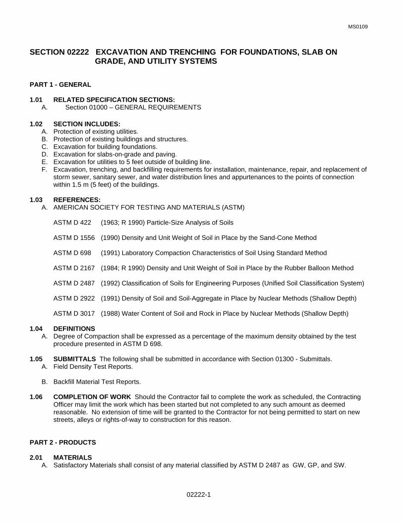
MS0109
02222-1
SECTION 02222 EXCAVATION AND TRENCHING FOR FOUNDATIONS, SLAB ON GRADE, AND UTILITY SYSTEMS
PART 1 - GENERAL 1.01 RELATED SPECIFICATION SECTIONS:
A. Section 01000 – GENERAL REQUIREMENTS
1.02 SECTION INCLUDES: A. Protection of existing utilities. B. Protection of existing buildings and structures. C. Excavation for building foundations. D. Excavation for slabs-on-grade and paving. E. Excavation for utilities to 5 feet outside of building line. F. Excavation, trenching, and backfilling requirements for installation, maintenance, repair, and replacement of
storm sewer, sanitary sewer, and water distribution lines and appurtenances to the points of connection within 1.5 m (5 feet) of the buildings.
1.03 REFERENCES:
A. AMERICAN SOCIETY FOR TESTING AND MATERIALS (ASTM)
ASTM D 422 (1963; R 1990) Particle-Size Analysis of Soils
ASTM D 1556 (1990) Density and Unit Weight of Soil in Place by the Sand-Cone Method
ASTM D 698 (1991) Laboratory Compaction Characteristics of Soil Using Standard Method
ASTM D 2167 (1984; R 1990) Density and Unit Weight of Soil in Place by the Rubber Balloon Method
ASTM D 2487 (1992) Classification of Soils for Engineering Purposes (Unified Soil Classification System)
ASTM D 2922 (1991) Density of Soil and Soil-Aggregate in Place by Nuclear Methods (Shallow Depth)
ASTM D 3017 (1988) Water Content of Soil and Rock in Place by Nuclear Methods (Shallow Depth) 1.04 DEFINITIONS
A. Degree of Compaction shall be expressed as a percentage of the maximum density obtained by the test procedure presented in ASTM D 698.
1.05 SUBMITTALS The following shall be submitted in accordance with Section 01300 - Submittals.
A. Field Density Test Reports.
B. Backfill Material Test Reports. 1.06 COMPLETION OF WORK Should the Contractor fail to complete the work as scheduled, the Contracting Officer may limit the work which has been started but not completed to any such amount as deemed reasonable. No extension of time will be granted to the Contractor for not being permitted to start on new streets, alleys or rights-of-way to construction for this reason. PART 2 - PRODUCTS 2.01 MATERIALS
A. Satisfactory Materials shall consist of any material classified by ASTM D 2487 as GW, GP, and SW.

MS0109
02222-2
B. Unsatisfactory Materials: Unsatisfactory materials shall be materials that do not comply with the requirements for satisfactory materials. Unsatisfactory materials include, but are not limited to those materials containing roots and other organic matter, trash, debris, frozen materials and stones larger than 75 mm (3 inches), and materials classified in ASTM D 2487, as PT, OH, and OL. Unsatisfactory materials also include man-made fills, refuse, or backfills from previous construction.
C. Cohesionless and Cohesive Materials:
1. Cohesionless materials shall include materials classified in ASTM D 2487 as GW, GP, SW, and SP. Materials classified as GM and SM will be identified as cohesionless only when the fines are nonplastic.
2. Cohesive materials include materials classified in ASTM D 2487 as GC, SC, CL, MH, and CH.
D. Unyielding Material: Unyielding material shall consist of rock and gravelly soils with stones greater than 75
mm (3 inches) in any dimension or as defined by the pipe manufacturer, whichever is smaller.
E. Unstable Material shall consist of materials too wet to properly support the utility pipe, conduit, or appurtenant structure.
F. Select Granular Material: Select granular material shall consist of well-graded sand, gravel, crushed gravel,
crushed stone or crushed slag composed of hard, tough and durable particles, and shall contain not more than 10 percent by weight of material passing a 0.075 mm (No. 200) mesh sieve and no less than 95 percent by weight passing the 25 mm (1-inch) sieve. The maximum allowable aggregate size shall be 100 mm (1 inch per foot) of pipe diameter, or the maximum size recommended by the pipe manufacturer, whichever is smaller.
G. Initial Backfill Material shall consist of select granular material or satisfactory materials free from rocks 2 mm
(3/4 inch) or larger in any dimension or free from rocks of such size as recommended by the pipe manufacturer, whichever is smaller.
H. Plastic Marking Tape: Plastic marking tape shall be acid and alkali-resistant polyethylene film, 152 mm (6 inches) wide with minimum thickness of 0.102 mm (0.004 inch). Tape shall have a minimum strength of 12.1 MPa (1750 psi) lengthwise and 10.3 MPa (1500 psi) crosswise. The tape shall be manufactured with integral wires, foil backing or other means to enable detection by metal detector when the tape is buried up to 3 feet deep. The tape shall be of a type specifically manufactured for marking and locating underground utilities. The metallic core of the tape shall be encased in a protective jacket or provided with other means to protect it from corrosion. Tape color shall be as specified in Table 1 and shall bear a continuous printed inscription describing the specific utility.
Table 1. Tape Color
Red: Electric Yellow: Gas, Oil, Dangerous Materials Orange: Telephone, Telegraph, Television, Police, and Fire Communications Blue: Water Systems Green: Sewer Systems
PART 3 - EXECUTION 3.01 PREPERATION
A. Verify the existence and location of underground utilities along the route of work. Omission from, or inclusion of, utility locations on the Drawings is not to be considered as the nonexistence of, or a definite location of, existing underground utilities. 1. Identify required lines, levels, contours, and datum. 2. Identify known underground, above ground and aerial utilities. Stake and flag locations. 3. Protect above and below grade utilities which are to remain.

MS0109
02222-3
4. Protect plants, shrubs, trees, lawns, and other features remaining as a portion of final landscaping. 5. Protect benchmarks, existing structures, fences, sidewalks, paving, and curbs from excavation
equipment and vehicular traffic. 3.02 PROTECTION
A. Existing Utilities: 1. Protect existing known utilities from damage due to work required under the scope of this contract. Any
damage to utilities will be repaired at the expense of the Contractor. 2. Before beginning trenching operations, obtain an Air Force Form 103, Civil Engineering Work
Clearance Permit for any underground or overhead utilities which may be on, or in close proximity to, the trenching areas.
B. Existing Buildings and Structures:
1. Guard against, and be responsible for, any movement, settlement, or collapse of adjacent buildings, sidewalks, structures, and underground and aboveground utilities. Repair damage done to the Base's property or any other property, on or off the premises, by reason of required work. Adequately brace walls during backfilling and compacting operations.
2. Items to be Relocated: Exercise the greatest possible care when items are scheduled for relocation. Use only skilled labor in the appropriate crafts. Identify items to be relocated, store and protect as directed.
C. Provide for surface drainage during the period of construction in a manner that protects trenches and
adjacent areas. Take precautions and temporary measures, such as temporary seeding, to prevent damage from erosion of freshly graded areas. This applies to damage of newly graded areas within construction limits and damage to adjacent properties by eroded materials.
3.03 EXCAVATION
A. General: 1. Excavation shall be performed to the lines and grades indicated. 2. During excavation, material satisfactory for backfilling shall be stockpiled in an orderly manner at a
distance from the banks of the trench equal to 1/2 the depth of the excavation, but in no instance closer than (2 feet).
3. Excavated material not required or not satisfactory for backfill shall be removed from the site. 4. Grading shall be done as may be necessary to prevent surface water from flowing into the excavation,
and any water accumulating therein, regardless of source, shall be removed to maintain the stability of the bottom and sides of the excavation. Continue to remove and dispose of water until utility lines, fittings, manholes, and other appurtenances are in place and sealed against the entrance of water. Water, earth, or any foreign materials shall not be allowed to enter the utility lines.
5. Unauthorized overexcavation shall be backfilled in accordance with section 02223, paragraphs 3.05 & 3.07 at no additional cost to the Government.
6. Correct unauthorized excavation at no extra cost to Government. 7. Remove unused excavated material from site in accordance with the following:
a. The contractor shall notify the Contracting Officer of the estimated or actual quantity of excess satisfactory soil, defined as those complying with ASTM D2487soil classification groups GW, GP, GM, SM, SW, and SP. The excess soil shall be removed and disposed of off base by the Contractor.
b. All unsatisfactory soil, as defined as those complying with ASTM D2487 soil classification groups GC, SC, ML, MH, CL, CH, OL, OH, and PT, shall be the Contractor's responsibility for disposal off base.
B. Trench Excavation: The trench shall be excavated as recommended by the manufacturer of the pipe to be installed. Trench walls below the top of the pipe shall be sloped, or made vertical, and of such width as recommended in the manufacturer’s installation manual. Where no manufacturer’s installation manual is available, trench walls shall be made vertical. Trench walls more than five feet high shall be shored, cut back to a stable slope, or provided with equivalent means of protection for employees who may be exposed

MS0109
02222-4
to moving ground or cave in. Trench walls which are cut back shall be excavated to at least the angle of repose of the soil. Special attention shall be given to slopes which may be adversely affected by weather or moisture content. The trench width below the top of pipe shall not exceed 24 inches plus pipe outside diameter (O.D.) for pipes of less than 24 inches inside diameter and shall not exceed 36 inches plus pipe outside diameter for sizes larger than 24 inches inside diameter. Where recommended trench widths are exceeded, redesign, stronger pipe, or special installation procedures shall be utilized by the Contractor. The cost of redesign, stronger pipe, or special installation procedures shall be borne by the Contractor without any additional cost to the Government.
1. Bottom Preparation: The bottoms of trenches shall be accurately graded to provide uniform bearing
and support for the bottom quadrant of each section of the pipe. Bell holes shall be excavated to the necessary size at each joint or coupling to eliminate point bearing. Stones of 1.5 inches or greater in any dimension, or as recommended by the pipe manufacturer, whichever is smaller, shall be removed to avoid point bearing.
2. Removal of Unyielding Material: Where unyielding material is encountered in the bottom of the trench, such material shall be removed a minimum of 4 inches below the required grade and replaced with suitable materials as provided in section 02223 ,paragraphs 3.05 & 3.07.
3. Removal of Unstable Material: Where unstable material in encountered in the bottom of the trench, such material shall be removed to the depth directed and replaced to the proper grade with Type “D” as provided in Section 02223, paragraph 2.01.D. When removal of unstable material is required due to the fault or neglect of the contractor in his performance of the work, the resulting material shall be excavated and replaced by the Contractor without additional cost to the Government.
4. Jacking, Boring, and Tunneling: Unless otherwise indicated, excavation shall be by open cut except that sections of a trench may be jacked, bored, or tunneled if, in the opinion of the Contracting Officer, the pipe, or duct can be safely and properly installed and backfill can be properly compacted in such sections.
C. Excavation for Appurtenances: Excavation for manholes, catch-basins, inlets, or similar structures shall be
sufficient to leave at least 12 inches clear between the outer structure surfaces and the face of the excavation or support members. Removal of unstable material shall be as specified above. When concrete or masonry is to be placed in an excavated area special care shall be taken not to disturb the bottom of the excavation. Excavation to the final grade level shall not be made until just before the concrete or masonry is to be placed.
3.04 SPECIAL REQUIREMENTS: Special requirements for both excavation and backfill relating to the specific utilities are as follows:
A. Water Lines: Trenches shall be of a depth to provide a minimum cover of 3-1/2 feet from the existing ground surface, or from the indicated finished grade, whichever is lower, to the top of the pipe.
B. Plastic Marking Tape: Warning tapes shall be installed directly above the pipe, at the depth of 12-18 inches
below finished grade unless otherwise shown. 3.05 TESTING: Testing shall be the responsibility of the Contractor and shall be performed at no additional cost to the Government.
A. Testing Facilities: Tests shall be performed by an approved commercial testing laboratory or may be tested by facilities furnished by the Contractor. No work requiring testing will be permitted until the facilities have been inspected and approved by the Contracting Officer. The first inspection shall be at the expense of the Government. Cost incurred for any subsequent inspection required because of failure of the first inspection will be charged to the Contractor.
B. Testing of Backfill Materials: Characteristics of backfill materials shall be determined in accordance with
particle size analysis of soils ASTM D 422 and moisture-density relations of soils ASTM D 1557. A minimum of one particle size analysis and one moisture-density relation test shall be performed on each different type of material used for bedding and backfill.
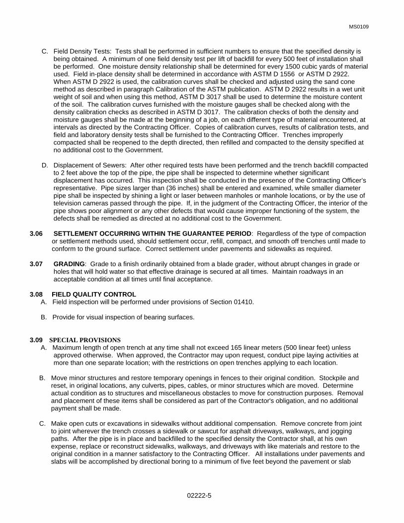
MS0109
02222-5
C. Field Density Tests: Tests shall be performed in sufficient numbers to ensure that the specified density is being obtained. A minimum of one field density test per lift of backfill for every 500 feet of installation shall be performed. One moisture density relationship shall be determined for every 1500 cubic yards of material used. Field in-place density shall be determined in accordance with ASTM D 1556 or ASTM D 2922. When ASTM D 2922 is used, the calibration curves shall be checked and adjusted using the sand cone method as described in paragraph Calibration of the ASTM publication. ASTM D 2922 results in a wet unit weight of soil and when using this method, ASTM D 3017 shall be used to determine the moisture content of the soil. The calibration curves furnished with the moisture gauges shall be checked along with the density calibration checks as described in ASTM D 3017. The calibration checks of both the density and moisture gauges shall be made at the beginning of a job, on each different type of material encountered, at intervals as directed by the Contracting Officer. Copies of calibration curves, results of calibration tests, and field and laboratory density tests shall be furnished to the Contracting Officer. Trenches improperly compacted shall be reopened to the depth directed, then refilled and compacted to the density specified at no additional cost to the Government.
D. Displacement of Sewers: After other required tests have been performed and the trench backfill compacted
to 2 feet above the top of the pipe, the pipe shall be inspected to determine whether significant displacement has occurred. This inspection shall be conducted in the presence of the Contracting Officer’s representative. Pipe sizes larger than (36 inches) shall be entered and examined, while smaller diameter pipe shall be inspected by shining a light or laser between manholes or manhole locations, or by the use of television cameras passed through the pipe. If, in the judgment of the Contracting Officer, the interior of the pipe shows poor alignment or any other defects that would cause improper functioning of the system, the defects shall be remedied as directed at no additional cost to the Government.
3.06 SETTLEMENT OCCURRING WITHIN THE GUARANTEE PERIOD: Regardless of the type of compaction or settlement methods used, should settlement occur, refill, compact, and smooth off trenches until made to conform to the ground surface. Correct settlement under pavements and sidewalks as required. 3.07 GRADING: Grade to a finish ordinarily obtained from a blade grader, without abrupt changes in grade or holes that will hold water so that effective drainage is secured at all times. Maintain roadways in an acceptable condition at all times until final acceptance. 3.08 FIELD QUALITY CONTROL A. Field inspection will be performed under provisions of Section 01410. B. Provide for visual inspection of bearing surfaces. 3.09 SPECIAL PROVISIONS A. Maximum length of open trench at any time shall not exceed 165 linear meters (500 linear feet) unless approved otherwise. When approved, the Contractor may upon request, conduct pipe laying activities at more than one separate location; with the restrictions on open trenches applying to each location.
B. Move minor structures and restore temporary openings in fences to their original condition. Stockpile and reset, in original locations, any culverts, pipes, cables, or minor structures which are moved. Determine actual condition as to structures and miscellaneous obstacles to move for construction purposes. Removal and placement of these items shall be considered as part of the Contractor's obligation, and no additional payment shall be made.
C. Make open cuts or excavations in sidewalks without additional compensation. Remove concrete from joint
to joint wherever the trench crosses a sidewalk or sawcut for asphalt driveways, walkways, and jogging paths. After the pipe is in place and backfilled to the specified density the Contractor shall, at his own expense, replace or reconstruct sidewalks, walkways, and driveways with like materials and restore to the original condition in a manner satisfactory to the Contracting Officer. All installations under pavements and slabs will be accomplished by directional boring to a minimum of five feet beyond the pavement or slab

MS0109
02222-6
edge. Asphalt settlement or concrete breakage over trenches shall be repaired as directed by the Contracting Officer.
D. The Contractor shall maintain all the streets he/she is working on until acceptance of the work. Maintenance
shall include grading the streets if they become bumpy or rough and the spraying of water on the streets to keep the dust down.
E. Re-sod areas disturbed by grading or construction.
F. Cleanup shall proceed directly behind backfilling to accommodate the return to normal conditions. The
amount of work on which complete cleanup has not been accomplished shall be limited to 330 linear meters (1,000 linear feet) for the entire job should the Contractor fail to diligently pursue job cleanup.
END OF SECTION

MS0109
02223-1
SECTION 02223: BACKFILLING & COMPACTION PART 1 GENERAL 1.01 RELATED SPECIFICATION SECTIONS: A. Section 01000 – GENERAL REQUIREMENTS 1.02 SECTION INCLUDES: A. Building perimeter backfilling. B. Site filling and backfilling. C. Fill under slabs-on-grade and paving. D. Consolidation and compaction. E. Fill for over-excavation. F. Sheet vapor retardant and fill. 1.03 REFERENCES: A. ANSI/ASTM C136 - Method for Sieve Analysis of Fine and Coarse Aggregates. B. ANSI/ASTM D698 - Test Methods for Moisture-Density Relations of Soils and Soil-Aggregate Mixtures,
Using 5.5 lb (2.49 kg) Rammer and 12 inch (304.8 mm) Drop. C. ANSI/ASTM D1556 - Test Method for Density of Soil in Place by the Sand-Cone Method. D. ANSI/ASTM D2922 - Test Methods for Density of Soil and Soil-Aggregate in Place by Nuclear Methods
(Shallow Depth). E. State of Florida Department of Transportation (DOT), Standard Specifications for Road and Bridge Construction (SSRBC), 1999 or later edition. 1.04 SUBMITTALS: A. Submit under provisions of Section 01300. B. Samples: Submit 10 lb. sample of each type of fill to testing laboratory, in airtight containers. PART 2 PRODUCTS 2.01 FILL MATERIALS: A. Type A - Crushed Stone: Pit run or river washed natural stone; free of shale, clay, friable material, sand,
debris; graded in accordance with ANSI/ASTM C136 within the following limits: Sieve Size Percent Passing 2 inches (5O mm) 100 One inch (25 mm) 95 3/4 inch (19 mm) 95 to 100 5/8 inch (16 mm) 75 to 100 3/8 inch (09 mm) 55 to 85 No. 4 35 to 60 B. Type B - Pea Gravel: Natural stone; washed, free of clay, shale, organic matter; graded in accordance
with ANSI/ASTM C136, to the following: 1. Minimum Size: 1/4 inch. 2. Maximum Size: 5/8 inch.
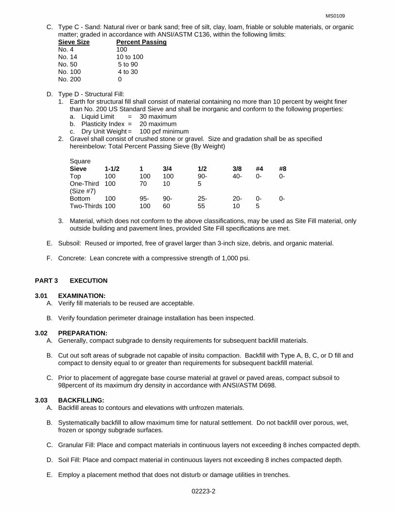
MS0109
02223-2
C. Type C - Sand: Natural river or bank sand; free of silt, clay, loam, friable or soluble materials, or organic matter; graded in accordance with ANSI/ASTM C136, within the following limits:
Sieve Size Percent Passing No. 4 100 No. 14 10 to 100 No. 50 5 to 90 No. 100 4 to 30 No. 200 0 D. Type D - Structural Fill: 1. Earth for structural fill shall consist of material containing no more than 10 percent by weight finer
than No. 200 US Standard Sieve and shall be inorganic and conform to the following properties: a. Liquid Limit = 30 maximum b. Plasticity Index = 20 maximum c. Dry Unit Weight = 100 pcf minimum 2. Gravel shall consist of crushed stone or gravel. Size and gradation shall be as specified
hereinbelow: Total Percent Passing Sieve (By Weight) Square Sieve 1-1/2 1 3/4 1/2 3/8 #4 #8 Top 100 100 100 90- 40- 0- 0- One-Third 100 70 10 5 (Size #7) Bottom 100 95- 90- 25- 20- 0- 0- Two-Thirds 100 100 60 55 10 5 3. Material, which does not conform to the above classifications, may be used as Site Fill material, only
outside building and pavement lines, provided Site Fill specifications are met. E. Subsoil: Reused or imported, free of gravel larger than 3-inch size, debris, and organic material. F. Concrete: Lean concrete with a compressive strength of 1,000 psi. PART 3 EXECUTION 3.01 EXAMINATION: A. Verify fill materials to be reused are acceptable. B. Verify foundation perimeter drainage installation has been inspected. 3.02 PREPARATION: A. Generally, compact subgrade to density requirements for subsequent backfill materials. B. Cut out soft areas of subgrade not capable of insitu compaction. Backfill with Type A, B, C, or D fill and
compact to density equal to or greater than requirements for subsequent backfill material. C. Prior to placement of aggregate base course material at gravel or paved areas, compact subsoil to
98percent of its maximum dry density in accordance with ANSI/ASTM D698. 3.03 BACKFILLING: A. Backfill areas to contours and elevations with unfrozen materials. B. Systematically backfill to allow maximum time for natural settlement. Do not backfill over porous, wet,
frozen or spongy subgrade surfaces. C. Granular Fill: Place and compact materials in continuous layers not exceeding 8 inches compacted depth. D. Soil Fill: Place and compact material in continuous layers not exceeding 8 inches compacted depth. E. Employ a placement method that does not disturb or damage utilities in trenches.

MS0109
02223-3
F. Maintain optimum moisture content of backfill materials to attain required compaction density. G. Slope grade away from building A minimum of 6-inches in 10 feet unless noted otherwise. H. Make grade changes gradual. Blend slope into level areas. I. Remove surplus backfill materials from site. J. Trench Backfill: Trenches shall be backfilled to the grade shown. The trench may be backfilled to 2 feet above the top of pipe prior to performing the required pressure tests. The joints and couplings shall be
left uncovered during the pressure test. The trench shall not be completely backfilled until all specified tests are performed.
3.04 TOLERANCES: A. Top surface of backfilling must be plus or minus one inch from required elevations. 3.05 FIELD QUALITY CONTROL: A. Field inspection and testing will be performed under provisions of Section 01410. B. Tests and analysis of fill material will be performed in accordance with ANSI/ASTM D698 and with
Section 01410. C. Compaction testing will be performed in accordance with ANSI/ASTM Dl556, ANSI/ASTM D2922, and
ANSI/ASTM D698 and with Section 01410. D. If tests indicate work does not meet specified requirements, remove work, replace and retest at no cost to
Government. E. Moisture & Density tests shall be in accordance with applicable sections of the Florida Dept. of
Transportation Standard Specifications for the specific type of paving. 3.06 PROTECTION OF FINISHED WORK: A. Re-compact fills subjected to vehicular traffic. 3.07 COMPACTION SCHEDULE: A. Slab-On-Grade, Footings and Bottom of Trenches: 1. Type D fill, 8 inches thick below bottom of floor slab/footing/trench, compacted to 100 percent. 2. Cover with Type A fill, if called for on the drawings, 4 inches thick, compacted to 100 percent. 3. Frequency of Tests: a. Slab-On-Grade: One per 1000 square feet of slab area or fraction thereof for each lift. b. Footings and Bottom of Trenches: One per 50 linear feet or fraction thereof. B. Exterior Side of Foundation Walls and Under Grass Areas: 1. Subsoil or Type D fill, to 6" below finish grade, compacted to 95 percent. 2. Remainder of 6" fill with topsoil, Compacted to 90 percent. 3. Frequency of Tests: a. Exterior Areas: One per 1000 square feet or fraction thereof. C. Fill Under Asphalt Paving (Base): 1. Type A fill, minimum 6" inches thick below bottom of finish paving, compacted to 100 percent; or 2. Minimum 6 inches thick lean concrete to minimum compressive strength of 1,000 psi. 3. Frequency of Tests: a. Base Course: One per 1000 square feet or fraction thereof. END OF SECTION

MS0109
02831-1
SECTION 02831: PVC COATED CHAIN LINK FENCING SYSTEM PART 1 GENERAL 1.01 RELATED SPECIFICATION SECTIONS: A. Section 01000 – GENERAL REQUIREMENTS 1.02 SECTION INCLUDES A. PVC Coated fence framework, fabric, components and accessories. B. Excavation for post bases; concrete foundation for posts and center drop for gates. C. Manual gates and related hardware. 1.03 REFERENCES A. ANSI/ASTM A123 - Zinc (Hot Dip Galvanized) Coatings on Iron and Steel Products. B. ANSI/ASTM F567 - Installation of Chain-Link Fence. C. ASTM A120 - Pipe, Steel, Black and Hot-Dipped Zinc Coated (Galvanized Welded and Seamless, for
Ordinary Uses. D. ASTM A121 - Zinc-Coated (Galvanized) Steel Barbed Wire. E. ASTM A153 - Zinc Coating (Hot-Dip) on Iron and Steel Hardware. F. ASTM A569 - Steel, Carbon (0.15 Maximum Percent), Hot-Rolled Sheet and Strip Commercial Quality. G. ASTM C94 - Ready-mixed Concrete. H. Chain Link Fence Manufacturers Institute (CLFMI) - Product Manual. I. FS RR-F-191 - Fencing, Wire and Post Metal (and Gates, Chain Link Fence Fabric, and Accessories). 1.04 SYSTEM DESCRIPTION A. Fence Height: 6'-0" feet with 3 strands of barbed wire at top, unless otherwise shown. B. Line Post Spacing: At intervals not exceeding 10 feet, set in poured concrete foundation. 1.05 SUBMITTALS A. Submit under provisions of Section 01300. B. Shop Drawings: Indicate plan layout, spacing of components, post foundation dimensions, hardware
anchorage, and schedule of components. C. Product Data: Provide data on fabric, posts, accessories, fittings and hardware. D. Samples: Submit two 6" x 6" samples of fence fabric; two samples each of hardware items, accessories,
etc., illustrating construction and colored finish. E. Manufacturer's Installation Instructions: Provide manufacturer's written installation instructions. 1.06 QUALITY ASSURANCE A. Perform Work in accordance with ANSI/ASTM F567, FS RR-F-191, and CLFMI. B. Maintain one copy of each document on site. 1.07 QUALIFICATIONS

MS0109
02831-2
A. Manufacturer: Company specializing in manufacturing the products specified in this Section with minimum three years documented experience.
B. Installer: Company specializing in the installation of chain-link fencing, approved by the fence
manufacturer, and three years documented experience. 1.08 FIELD MEASUREMENTS A. Verify that field measurements are as indicated on shop drawings. PART 2 PRODUCTS 2.01 ACCEPTABLE MANUFACTURERS A. Anchor Fence Company, Boundary Fence & Railing Systems, Inc., Semmerling, Southeastern Wire. B. Substitutions: Under provisions of Section 01000. 2.02 MATERIALS A. Framing (Steel): ASTM A120; Schedule 40 steel pipe, standard weight, one piece without joints. B. Fabric Wire (Steel): ASTM A392 zinc coated wire fabric or ASTM A116 galvanized wire fabric. C. Barbed Wire: ASTM A121 galvanized steel wire, with galvanized steel barbs; 3 strands, 4 points at 3-
inch o.c. D. Concrete: Type specified in Section 03300. 2.03 COMPONENTS A. Line Posts: 1.9-inch diameter up to 6 feet high; 2.38-inch diameter, 6-8 feet high. B. Corner, Gate and Terminal Posts: 3.5-inch diameter minimum, increase diameter as required to suite
project conditions. C. Top and Brace Rail: 1.66-inch diameter, plain end, sleeve coupled. D. Gate Frame: 1.66-inch diameter for welded fittings and truss rod fabrication. E. Fabric: 2 inch diamond mesh interwoven wire, 9 gage diameter core wire unless otherwise indicated on
the drawings, top selvage twisted tight, bottom selvage knuckle end closed. F. Tension Wire: 6 gage thick steel, single strand. G. Tension Band: 12 gauge, galvanized, pressed steel, plain ends. H. Tension Strap: 0.75" x 3/16" thick steel. I. Tie Wire: Aluminum alloy wire. 2.04 ACCESSORIES A. Caps: Cast steel galvanized or malleable iron galvanized; sized to post diameter, set screw retainer. B. Fittings: Sleeves, bands, clips, rail ends, tension bars, fasteners and fittings; galvanized steel. C. Extension Arms: Cast steel galvanized, to accommodate 3 strands of barbed wire, single arm, sloped to
45 degrees. D. Gate Hardware: Fork latch with gravity drop, Center gate stop and drop rod, Mechanical keepers; two 180-degree gate hinges per leaf and hardware for padlock.

MS0109
02831-3
2.05 FINISHES A. Materials, Components and Fabric: Vinyl coating, dark brown color, fused bonded, on fabric, framework
and fittings shall conform to the following: i. Fabric: ASTM F688, Class 2B, 7-12 mils thickness. ii. Framework: ASTM F 1234, 10-14 mils thickness. iii. Fittings, ASTM F 626, 10-14 mils thickness. PART 3 EXECUTION 3.01 INSTALLATION A. Install framework, fabric, accessories and gates in accordance with ANSI/ASTM F567 and manufacturer's
instructions. B. Set intermediate, terminal and gate posts plumb, in concrete footings with top of footing 2 inches above
finish grade. Slope top of concrete for water runoff. C. Line Post Footing Depth Below Finish Grade: ANSI/ASTM F567. D. Corner, Gate and Terminal Post Footing Depth Below Finish Grade: ANSI/ASTM F567. E. Brace each gate and corner post to adjacent line post with horizontal center brace rail and diagonal truss
rods. Install brace rail, one bay from end and gate posts. F. Provide top rail through line post tops and splice with 6-inch long rail sleeves. G. Install center and bottom brace rail on corner gate leaves. H. Stretch fabric between terminal posts or at intervals of 100 feet maximum, whichever is less. I. Position bottom of fabric 2 inches above finished grade. J. Fasten fabric to top rail, line posts, braces, and bottom tension wire with tie wire at maximum 15 inches
on centers. K. Attach fabric to end, corner, and gate posts with tension bars and tension bar clips. L. Install bottom tension wire stretched taut between terminal posts. M. Install support arms sloped outward and attach barbed wire; tension and secure. N. Do not swing gate from building wall; provide gate posts. O. Install gate with fabric and barbed wire overhang to match fence. Install three hinges per leaf, latch,
catches, drop bolt, foot bolts and sockets, retainer and locking clamp. P. Provide concrete center drop to footing depth and drop rod retainers at center of double gate openings. 3.02 ERECTION TOLERANCES A. Maximum Variation From Plumb: 1/8" inch in 6 feet. B. Maximum Offset From True Position: 1 inch. C. Components shall not infringe adjacent property lines. 3.03 CLEAN-UP A. Upon completion of work, remove all excess material, trash, boxes, wrappings, scraps, etc. from the area.
Grade and rake the area below the fence leaving the area clean with the proper clearance between the finish grade and bottom of fence.
END OF SECTION

MS0810
02938-1
SECTION 02938 SODDING PART 1 GENERAL 1.01 RELATED SPECIFICATION SECTIONS: A. Section 01000 – GENERAL REQUIREMENTS 1.02 DESCRIPTION OF WORK A. Extent of landscape work generally includes: 1. Weed Treatment 2. Soil Preparation 3. Sodding 4. Reconditioning Existing Turf Areas 5. Cleanup and Protection 6. Maintenance B. Sub-grade Elevations: Excavation, filling and grading required to establish elevations shown on drawings
are not specified in this section. Refer to Earthwork sections. Subcontractors shall coordinate with contractor on responsibility for earthwork.
1.03 REFERENCES A. General: Planting materials shall meet or exceed the Specifications of Federal, State and local laws
requiring inspection for plant disease and insect control. B. Sod shall conform to the following document that is to be considered part of these Specifications:
"Guideline Specifications to Sodding" American Sod Producers Association. (ASPA) 1.04 QUALIFICATIONS
A. The contractor shall have not less than 3 years experience installing sod.
1.05 SUBMITTALS AND INSPECTIONS A. Inspections: All necessary state, federal, and other inspection certificates shall accompany the invoice
for each shipment or order for sod materials as approval at the site or elsewhere
B. Analysis and Standards: Pack standard products with manufacturer's certified analysis. For other materials, provide analysis by recognized laboratory made in accordance with methods established by the Association of Official Agricultural Chemists, wherever applicable.
C. Provide the following samples prior to installation: 1. Herbicide: Label from container or supplier's brochure. 2. Fill Sand: One-ounce sample of sand. 3. Soil Amendments: Labels from all bags. 4. Sod: Submit sod grower's certification of grass species. Identify source location. 5. Soil Test: Contractor will have existing soil tested by an approved soil laboratory. Results of test shall
be forwarded to the Contracting Officer in accordance with Section 01410 of the specifications. The samples tested shall consist of a representative mixture from the site. Cost of the soil test and all additives at rates recommended by the laboratory shall be included in the base bid. Soil Test shall include these items and amendment rates of each needed for the specified sod: pH factor, Potassium, Phosphorus, Calcium, Magnesium, N-P-K, and a nematode count.
1.06 JOB CONDITIONS A. Basic Regulations: Sodding operations shall be conducted under favorable weather conditions during the
seasons, which are normal for such work as determined by acceptable practice in the locality. Contractor is hereby notified of active utilities and caution shall be exercised to avoid interruption of services. Contractor is responsible for replacement of any existing buried utilities, irrigation lines, etc., if they are broken during the planting operations. Contractor shall obtain a digging permit and contact the appropriate utility to have their location marked. If not, any damage to utilities will be repaired at the contractor's expense. Contractor shall protect existing paved areas, curb/gutters, walks, etc. The contractor will repair any damage.

MS0810
02938-2
B. When conditions detrimental to sod growth are encountered during soil preparation or planting, such as rubble fill, adverse drainage conditions, or obstructions, notify Contracting Officer and correct before planting.
C. Sequence of Work: Sod after irrigation and final grades are established unless otherwise acceptable to
Contracting Officer. Protect existing lawn areas and promptly repair damage to lawns resulting from operations.
1.07 WARRANTY & REPLACEMENT A. Contractor shall guarantee that at the end of 60 days following final building acceptance, all sod areas
shall have established grass that is uniform in color and quality, and is reasonably free from visible imperfections. Any sod areas not in this condition will be replaced at no expense to the government. Inspection to determine the condition of the sod areas will be made by the Contracting Officer upon receiving such a request from contractor.
B. Contractor shall not be held responsible for damages to sod areas due to government neglect,
hurricanes, tornadoes, or for damage caused by theft or vandalism, other contractor's work on the site, application of fertilizers, and pesticides or other materials not applied by him. The cost to repair damage caused by another contractor shall be paid for by the contractor responsible for the damage. This contractor shall immediately notify the prime contractor of the damage, etc.
C. Repair: When any portion of the surface becomes gullied or otherwise damaged due to drainage
conditions, the affected portion shall be repaired to reestablish condition and grade of soil to as it was prior to injury as directed. Repair work required shall be performed without cost to the government. Repair shall be made within 10 days or as soon as weather conditions are satisfactory for planting.
PART 2 PRODUCTS
2.01 PRODUCT DELIVERY, STORAGE, AND HANDLING A. Packaged Materials: Deliver packaged materials in original containers showing weight, analysis and
name of manufacturer. Protect materials from deterioration during delivery, and while stored at site. B. Deliver sod on pallets after preparations for sodding have been completed and lay immediately. Protect
sod from drying out. Use all means necessary to protect sod materials before, during and after installation and to protect the installed work and materials of all other trades.
C. Do not deliver more sod than can be laid in 24 hours. Sod not laid within 24 hours of delivery will
be rejected. 2.02 SOD
A. Sod Schedules: Contractor shall furnish the sod required to accomplish the work and leave no bare areas. 1. General lawn use at buildings: Argentine Bahia, Paspalum Notatum. 2. Large areas, airfield. etc.: Common Bermudagrass, Cynodon dactylon. 3. Playing fields; baseball, soccer, football, etc.: "Tifway" Bermuda, Cynodon dactylon. 4. General lawn use Soundside area: Floratam St. Augustine, Stenotaphrum secundatum.
B. Provide strongly rooted sod of the type indicated on the drawings, ASPA approved field grown grade. All
sod shall be nursery grown under climatic conditions similar to those in the locality of the project for a minimum of two (2) years and machine cut and harvested to pad thickness of 3/4" to 1 1/4", excluding top growth and thatch. Provide only sod capable of vigorous growth and development when planted with maximum five percent (5%) deviation in either length, width, or pad thickness. Broken pads or pads with uneven ends will not be acceptable.
C. Sod shall have root development, which will support its own weight, without tearing, when suspended
vertically by its two upper corners. D. Sod shall be clear of non-specified grasses and weeds with not more than 3 weeds per pallet (500 SF).

MS0810
02938-3
E. Contracting Officer reserves the right to inspect grass areas from time of installation to Final Acceptance. The time of inspection shall be after the grass has gone not mowed for a minimum of two weeks. Any evidence of non-specified grasses or weeds will be cause for rejection and replacement of the unacceptable lawn areas.
2.03 SOIL AMENDMENT A. Fill Sand: Clean yellow fill, No. 4 to 200 Sand, pH 5.5 - 6.5. B. Soil Amendment for All Sod (See 3.04 A for ratios): 1. Gro-Tone Bed Mix. 2. Black Kow Cow manure. 2.04 MISCELLANEOUS LANDSCAPE MATERIALS
A. Water: Furnished by government or provided by the project irrigation system. Contractor shall provide hose and other watering equipment.
B. Edging (if indicated on the drawings): Black Aluminum, 1/8" x 4" with stakes. Curve-Rite Aluminum
Edging (800) 366-2878, Sure-Loc (800) 787-3562, PermaLoc (800) 356-9660 or approved equal. C. Mulch: Longleaf Pine Straw. Freshly baled, dry, and free of debris, leaves, insects, and briars. D. Wood Pegs: Softwood, sufficient size and length to ensure anchorage of sod on slopes. E. Herbicide (For Pre-Sod Treatment of Weeds, Etc.): Round-Up by Monsanto or approved equal. F. Herbicide (During Maintenance Period): Submit Label / Manufacturer's instructions. G. Fertilizer (for maintenance period): Gro-Tone Lawn Special 16-4-8 or approved equal. For winter
applications use approved winterizer. PART 3 EXECUTION 3.01 WEED TREATMENT A. All site locations disturbed by site construction and to receive sod where weeds exist shall receive an
initial treatment of post-emergent herbicide. Planting areas shall not be disturbed for fourteen (14) days following each application of herbicide. This treatment shall be repeated as required so that no weeds are present at the date of final inspection of the Project and at the conclusion of the 60-day maintenance period.
B. Post-emergent weed treatment includes removal of weeds and other undesirable ground cover
vegetation and shall be accomplished a minimum of fourteen (14) days prior to soil preparation for sodding operations.
C. Care shall be taken not to affect existing trees or shrubs to be saved on the site. Also care will be taken
not to affect plants on adjacent site. 3.02 WEED TREATMENT PROCEDURE A. Mow grass and/or existing weeds in designated areas to 3" height. B. Spray herbicide on a day that is not rainy or windy or below 65 degrees F. C. Do not disturb soil for 14 days. D. After 14 days, mechanically rake soil when the soil is not excessively hard or dry (water the soil if
necessary). E. Remaining dead material shall be allowed to accumulate in place and shall be incorporated into the soil
through the roto-tilling of the soil preparation work.

MS0810
02938-4
3.03 SOIL PREPARATION AND BED LAYOUT A. Contractor shall report immediately upon his awareness, any site condition or situation of the contiguous
landscape that would cause flooding, washing or concentration of excess surface water to the areas receiving planting or lawn.
B. Prior to placement of any required fill sand, cultivate sub-grade to a minimum of four inches (4"). Remove
stones over one-half inch diameter (1/2") and sticks, roots, rubbish and other extraneous debris of any dimension.
C. Fill sand is to be placed to obtain uniform site grade and proper drainage. Compact to a minimum
standard density of 80%. D. Prior to fine grading install Edging and Stakes per manufacturer's instructions. Layout of Edging is as
indicated on the drawings. Straight runs are to be straight to within 1/2" and arcs are to be round to within 1/2" of plan dimensions. All Edging shall be truly square to other Edging or Sidewalks, etc. where shown.
E. Irrigation work, if included, shall be completed after roto-tilling and compaction, but prior to fine grading. F. Fine Grading: The entire area shall be raked smooth after removing all rocks, roots and debris one-half
inch (1/2") in diameter or larger. Make changes to grade gradual and blend slopes into level areas. The site shall be free from irregular surface changes and shall vary uniformly between fixed elevations.
G. Fine grade grass areas to smooth, even surface with loose, uniformly fine texture. Roll, rake and drag
lawn areas, remove ridges and fill depressions, as required to meet finish grade. Limit fine grading to areas which can be planted immediately after grading.
H. Allow for grass thickness in areas to be sodded and mulch thickness in shrub beds. Finish grade of soil
shall be two inches (2") below top of pavement in all areas. 3.04 SOIL MIXTURE A. Mix specified soil amendment (see Section 2.01 A) by roto-tilling to a depth of four (4) inches: 1. Fifty (50) LBS of Bed Mix per One Thousand (1000) SF of Sod. 2. One Hundred (100) LBS of Cow Manure per One Thousand (1000) SF of Sod. B. Before mixing, clean topsoil of roots, plants, sod, stones, lumps, existing irrigation materials, and other
extraneous materials harmful or toxic to sod growth. (maximum acceptable lump size is 1/2".) C. Contractor may be required to mix all ingredients of the planting soil mix in the presence of the project
inspector. All ingredients shall be thoroughly blended to provide a homogeneous mixture. 3.05 PREPARATION OF SOD AREAS A. Bed preparation shall be done by hand within the drip-line of existing trees to protect the tree's roots. B. Planting beds with weed growth shall be treated as necessary to remove weeds and re-inspected. No
beds shall be accepted with weeds or unspecified grass. 3.06 SODDING NEW LAWNS A. Soil shall be prepared prior to sodding. See Sections 3.01 - 3.05. B. Lay sod within 24 hours from time of stripping. Do not plant dormant sod or if ground is frozen. Do not
use any piece of sod less than .5 SF (one-half square foot). Do not harvest or transport sod when moisture content may adversely affect sod survival. Protect sod from sun, wind, and dehydration prior to installation. Do not tear, stretch, or drop sod during handling and installation.
C. Prior to placement of sod, water soil thoroughly to obtain at least 6" (six) inches penetration into the soil
below the sod. Do not lay sod on dry or frozen ground.

MS0810
02938-5
D. Lay sod to form a solid mass with tightly fitted joints. Tightly butt ends and sides of sod strips; do not
overlap. Stagger strips to offset joints in adjacent courses. Continuously rake soil in area of installation to assure a smooth finish grade. Tamp or roll lightly to ensure contact with sub-grade. Work sifted soil into minor cracks between pieces of sod; remove excess to avoid smothering of adjacent grass.
E. Neatly and cleanly edge sod with a sharpened instrument so as not to fray edges of sod. Continuously
re-sharpen during edging process. F. Sod indicated areas within contract limits and areas adjoining contract limits disturbed as a result of
construction operations. G. On slopes of 3:1 and steeper, lay sod perpendicular to slope and secure every row with wooden pegs at
a maximum of two (2) feet on center. Drive pegs flush with top of sod pad. H. Firmly press sod into contact with soil with roller weighing 100-150 pounds per lineal foot. I. Water sod thoroughly with a fine spray immediately after planting to obtain at least six inches (6")
penetration into the soil below the sod. 3.07 RECONDITIONING EXISTING TURF AREAS A. Provide soil amendments, sod, fill sand and all other materials necessary to return turf to its original
condition before the start of the contract. B. Recondition existing turf areas damaged by contractor's operations including storage for materials and
equipment and movement of vehicles. Re-grade as required. Fill low spots and meet new finish grades. Cultivate bare and compacted areas thoroughly to provide a suitable soil for sod.
C. Water newly reconditioned turf areas as required to establish turf. (60 Days Minimum). 3.08 MULCHING A. Dress Mulching: Within two days after planting not less than three inches (3") of mulch shall be placed
on entire area of planting beds, and not less than four inches (4") over shrub and tree pits. B. Edge mulch with a round-point shovel where beds are next to turf or walkways so that mulch is pushed
into soil and is kept in beds. 3.09 MAINTENANCE A. Begin maintenance immediately after planting and continue until sixty (60) days after final acceptance of
the project, or longer as required to establish the turf. B. Maintain newly sodded lawn areas by watering, fertilizing, weeding, mowing, trimming, and other
operations such as rolling, re-grading and replanting as required to establish a smooth, acceptable lawn, free of eroded or bare areas. Immediately replace sod in areas showing deterioration.
C. Apply herbicides and insecticides that will not inhibit growth but will prevent weed and insect damage to
turf. Comply with State of Florida and manufacturer's requirements for application of herbicides and insecticides.
D. After sod is rooted, apply Fertilizer at the rate of Ten (10) Lbs. per 1000 SF. If winter apply the approved
winterizer at the medium rate listed on the bag. E. Watering Schedule: Watering schedule is to include the duration and frequency each irrigation zone will
run per week; or, if there is no irrigation system the schedule of the watering truck or hand watering. This will be worked out jointly with the irrigation contractor and shall be programmed on to the controller after review by BCE. Program shall be submitted to Contracting Officer as part of the final acceptance process.
3.10 CLEANUP AND PROTECTION A. During landscape work, all pallets, sod pieces, debris, and sand on pavement, shall be removed daily.

MS0810
02938-6
B. Any excess excavated subsoil or topsoil shall be removed from the site. C. After sodding operations are finished, all paved areas which may have become strewn with soil or other
material shall be thoroughly cleaned by sweeping, and if necessary, power washing. D. Protect landscape work and materials from damage due to landscape operations, operations by other
contractors and trades and trespassers. Maintain protection during installation and maintenance periods. Treat, repair, or replace damaged landscape work as directed.
3.11 INSPECTION AND ACCEPTANCE A. The completed sod will be inspected at the time of the final inspection. Sod will also be inspected at the
end of the 60-day maintenance period. B. Where inspected landscape work does not comply with requirements, replace rejected work and continue
specified maintenance until re-inspected and found to be acceptable. Remove rejected and materials promptly from the project site.
END OF SECTION

MS0109
03100-1
SECTION 03100: CONCRETE FORMWORK PART 1 GENERAL 1.01 SECTION INCLUDES A. Formwork for cast-in place concrete, with shoring, bracing and anchorage. B. Openings for other work. C. Form accessories. D. Form stripping. 1.02 PRODUCTS INSTALLED BUT NOT FURNISHED UNDER THIS SECTION A. See applicable section of the specifications. 1.03 REFERENCES A. ACI 301 - Specification for Structural Concrete for Buildings. B. ACI 318 - Building Code Requirements for Reinforced Concrete. C. ACI 347 - Recommended Practice For Concrete Formwork. D. PS-1 - Construction and Industrial Plywood. 1.04 DESIGN REQUIREMENTS A. Design, engineer and construct formwork, shoring and bracing to conform to code requirements; resultant
concrete to conform to required shape, line and dimension. 1.05 SUBMITTALS A. Submit under provisions of Section 01300. B. Shop Drawings: Indicate pertinent dimensions, materials, bracing, and arrangement of joints and ties. 1.06 QUALITY ASSURANCE A. Perform Work in accordance with ACI 318. B. Maintain one copy of each document on site. 1.07 QUALIFICATIONS A. Design formwork under direct supervision of a Professional Structural Engineer experienced in design of
this work and licensed in the State of Florida. 1.08 REGULATORY REQUIREMENTS A. Conform to applicable code for design, fabrication, erection and removal of formwork. 1.09 DELIVERY, STORAGE, AND HANDLING A. Deliver, store, protect and handle products to site under provisions of Section 01600. B. Store off ground in ventilated and protected manner to prevent deterioration from moisture. 1.10 COORDINATION A. Coordinate this section with other sections of work, which require attachment of components to formwork. B. If formwork is placed after reinforcement resulting in insufficient concrete cover over reinforcement,
request instructions from the Contracting Officer before proceeding.

MS0109
03100-2
PART 2 PRODUCTS 2.01 WOOD FORM MATERIALS A. Softwood Plywood: PS 1, C Grade. 2.02 FORMWORK ACCESSORIES A. Form Ties: Snap-off type, galvanized metal, adjustable length, 1 inch back break dimension, free of
defects that could leave holes larger than l inch in concrete surface. B. Form Release Agent: Colorless mineral oil, which will not stain concrete, or absorb moisture. C. Corners: Chamfered type, 3/4 inch x 3/4 inch size. PART 3 EXECUTION 3.01 EXAMINATION A. Verify lines, levels and centers before proceeding with formwork. Ensure that dimensions agree with
Drawings. 3.02 EARTH FORMS A. Earth forms are not permitted. 3.03 ERECTION - FORMWORK A. Erect formwork, shoring and bracing to achieve design requirements, in accordance with requirements of
ACI 301. B. Provide bracing to ensure stability of formwork. Shore or strengthen formwork subject to overstressing by
construction loads. C. Arrange and assemble formwork to permit dismantling and stripping. Do not damage concrete during
stripping. Permit removal of remaining principal shores. D. Align joints and make watertight. Keep form joints to a minimum. E. Obtain approval before framing openings in structural members, which are not indicated on Drawings. F. Provide chamfer strips on exposed external corners of concrete edge. 3.04 APPLICATION - FORM RELEASE AGENT A. Apply form release agent on formwork in accordance with manufacturer's recommendations. B. Apply prior to placement of reinforcing steel, anchoring devices, and embedded items. C. Do not apply form release agent where concrete surfaces will receive special finishes, which are effected
by agent. Soak inside surfaces of untreated forms with clean water. Keep surfaces coated prior to placement of concrete.
3.05 INSERTS, EMBEDDED PARTS, AND OPENINGS A. Provide formed openings where required for items to be embedded in or passing through concrete work. B. Locate and set in place items which will be cast directly into concrete. C. Coordinate work of other Sections in forming and placing openings, slots, reglets, recesses. chases,
sleeves, bolts. anchors, and other inserts. D. Install accessories in accordance with manufacturer's instructions, straight, level, and plumb. Ensure
items are not disturbed during concrete placement.
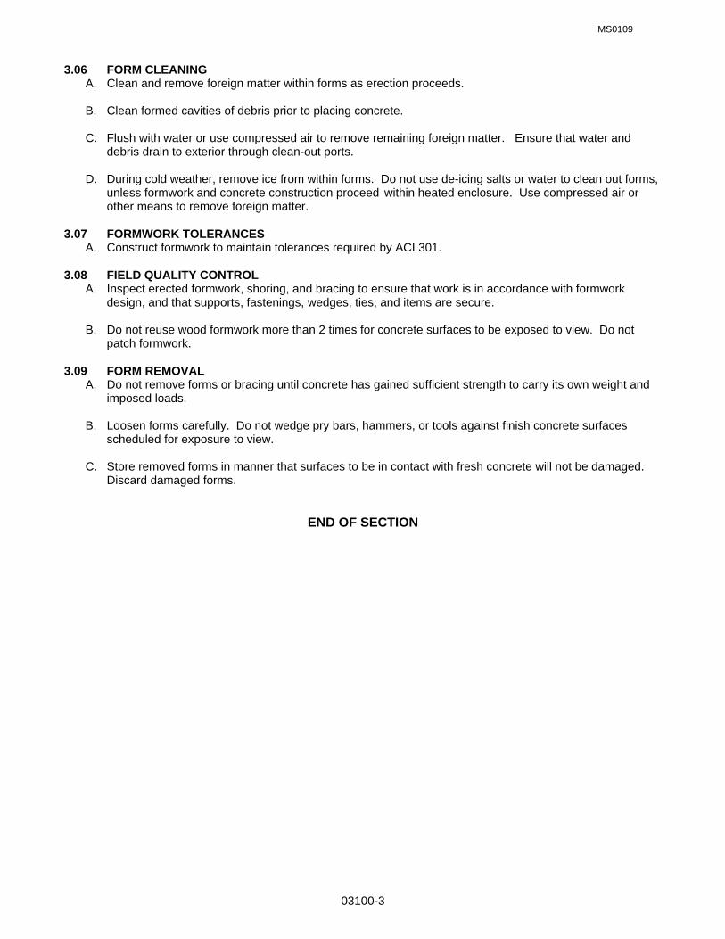
MS0109
03100-3
3.06 FORM CLEANING A. Clean and remove foreign matter within forms as erection proceeds. B. Clean formed cavities of debris prior to placing concrete. C. Flush with water or use compressed air to remove remaining foreign matter. Ensure that water and
debris drain to exterior through clean-out ports. D. During cold weather, remove ice from within forms. Do not use de-icing salts or water to clean out forms,
unless formwork and concrete construction proceed within heated enclosure. Use compressed air or other means to remove foreign matter.
3.07 FORMWORK TOLERANCES A. Construct formwork to maintain tolerances required by ACI 301. 3.08 FIELD QUALITY CONTROL A. Inspect erected formwork, shoring, and bracing to ensure that work is in accordance with formwork
design, and that supports, fastenings, wedges, ties, and items are secure. B. Do not reuse wood formwork more than 2 times for concrete surfaces to be exposed to view. Do not
patch formwork. 3.09 FORM REMOVAL A. Do not remove forms or bracing until concrete has gained sufficient strength to carry its own weight and
imposed loads. B. Loosen forms carefully. Do not wedge pry bars, hammers, or tools against finish concrete surfaces
scheduled for exposure to view. C. Store removed forms in manner that surfaces to be in contact with fresh concrete will not be damaged.
Discard damaged forms.
END OF SECTION

MS0109
03200-1
SECTION 03200: CONCRETE REINFORCEMENT PART 1 GENERAL 1.01 SECTION INCLUDES A. Reinforcing steel bars, wire fabric and accessories for cast in place concrete. 1.02 REFERENCES A. ACI 318 - Building Code Requirements For Reinforced Concrete. B. ANSI/ASTM A185 - Welded Steel Wire Fabric for Concrete Reinforcement. C. ASTM A615 - Deformed and Plain Billet Steel Bars for Concrete Reinforcement. D. CRSI - Concrete Reinforcing Steel Institute Manual of Practice. E. CRSI 63 - Recommended Practice For Placing Reinforcing Bars. F. CRSI 65 - Recommended Practice For Placing Bar Supports, Specifications and Nomenclature. 1.03 SUBMITTALS A. Submit under provisions of Section 01300. B. Shop Drawings: Indicate bar sizes, spacings, locations, and quantities of reinforcing steel and wire fabric,
bending and cutting schedules, and supporting and spacing devices and anchor bolt layout. C. Manufacturer's Certificate: Certify that products meet or exceed specified requirements. 1.04 QUALITY ASSURANCE A. Perform Work in accordance with CRSI 63, 65 and Manual of Practice. B. Maintain one copy of each document on site. C. Submit certified copies of mill test report of reinforcement materials analysis. 1.05 COORDINATION A. Coordinate with placement of formwork, formed openings and other Work. PART 2 PRODUCTS 2.01 REINFORCEMENT A. Reinforcing Steel: 1. ASTM A615, 60-ksi yield grade 2. Deformed billet steel bars. B. Welded Steel Wire Fabric: ASTM A185 Plain Type; in flat sheets or coiled rolls; plain finish. C. Slab on Grade Reinforcement shall be: 1. #3 rebar at 12” o/c each way. 2.02 ACCESSORY MATERIALS A. Tie Wire: Minimum 16 gauge annealed type. B. Chairs, Bolsters, Bar Supports, Spacers: Sized and shaped for strength and support of reinforcement
during concrete placement conditions including load bearing pad on bottom to prevent vapor barrier puncture. Brick or CMU may not be used for support except as permitted in paragraph 1.02 above.
2.03 FABRICATION

MS0109
03200-2
A. Fabricate concrete reinforcing in accordance with ACI 318.
PART 3 EXECUTION 3.01 PLACEMENT A. Place, support and secure reinforcement against displacement. Do not deviate from required position. B. Do not displace or damage vapor barrier. C. Accommodate placement of formed openings. D. Conform to ACI 318 for concrete cover over reinforcement. 3.02 FIELD QUALITY CONTROL A. Field inspection and testing will be performed under provisions of Section 01410. END OF SECTION
MS0109
03251-1
SECTION 03251: CONSTRUCTION, ISOLATION AND CONTRACTION JOINTS PART 1 GENERAL 1.01 RELATED SPECIFICATION SECTIONS: A. Section 01000 – GENERAL REQUIREMENTS 1.02 WORK INCLUDED A. Forming integral isolation and contraction joints in concrete. B. Visually concealing expansion joints in concrete. C. Isolation and contraction joint devices associated with concrete work, including joint sealant. 1.03 REFERENCES A. ANSI/ASTM D994 - Preformed Expansion Joint Filler for Concrete (Bituminous Type). 1.04 SUBMITTALS A. Provide 12-inch long sample of expansion joint and control joint under provisions of Section 01300. B. Submit manufacturer's installation instructions under provisions of Section 01300. PART 2 PRODUCTS 2.01 JOINT TYPES, DEVICES AND FILLER MATERIALS A. Isolation Joint (IJ): Asphalt impregnated glass fiber filler Type A: ASTM D994, minimum 1/2" inch thick or
as indicated on drawings. B. Exterior Construction Joint (ECJ): Integral galvanized steel, formed to tongue and groove profile, with
removable top strip exposing sealant trough, and ribbed steel spikes with tongue to fit top screed edge. C. Exterior Tooled Contraction Joint (ETC): Tool formed joint located between isolation joints. C. Interior Transverse Construction Joint (ITC): Integral galvanized steel, formed to tongue and groove
profile, with ribbed steel spikes with tongue to fit top screed edge. D. Interior Longitudinal Contraction Joint (ILC): Joint that is saw cut into the surface of the concrete as soon
as the concrete has hardened sufficiently to prevent aggregates from becoming dislodged by the cutting process (usually 4-12 hours after the concrete hardens) and completed before drying shrinkage causes cracking. Initial cut shall be 1/3 the thickness of the slab. After concrete has cured, joints shall be re-cut to ½” width x ½” depth. Provide foam backer rod and fill joint with sealant flush with top of slab.
E. All joint material shall match the thickness of the slab. F. Sealant: ASTM D1190: Hot applied synthetic rubber compound. G. Sealant: Cold applied two-part liquid neoprene. PART 3 EXECUTION 3.01 INSTALLATION A. Locate and form construction, isolation and contraction joints and identify as per above.. B. Place formed construction and isolation joints in floor slab pattern placement sequence. Set top screed
to required elevations. Secure to resist movement of wet concrete.
MS0109
03251-2
C. Install joint fillers and sealants in accordance with manufacturer's instructions. Use primers of type recommended by joint filler and sealant manufacturer.
D. Saw-cut contraction joints as per above. END OF SECTION

MS0109
03300-1
SECTION 03300 CAST-IN-PLACE CONCRETE PART 1 GENERAL 1.01 RELATED SPECIFICATION SECTIONS: A. Section 01000 – GENERAL REQUIREMENTS 1.02 SECTION INCLUDES A. Slabs on grade including integral footings, beams, columns, and elevated floor and roof slabs. B. Equipment pads and thrust blocks. 1.03 REFERENCES A. ACI 301 - Structural Concrete for Buildings. B. ACI 302 - Guide for Concrete Floor and Slab Construction. C. ACI 304 - Recommended Practice for Measuring, Mixing, Transporting and Placing Concrete. D. ACI 305R - Hot Weather Concreting. E. ACI 306R - Cold Weather Concreting. F. ACI 308 - Standard Practice for Curing Concrete. G. ACI 318 Building Code Requirements for Reinforced Concrete. H. ASTM C33 - Concrete Aggregates. I. ASTM C94 - Ready-Mixed Concrete. J. ASTM C150 - Portland Cement. K. ASTM C260 - Air Entraining Admixtures for Concrete. L. ASTM C494 - Chemicals Admixtures for Concrete. M. ASTM C618 - Fly Ash and Raw or Calcinated Natural Pozzolan for Use as a Mineral Admixture in
Portland Cement Concrete. N. ASTM E1745-97 Standard Specifications for Water Vapor Retarders Used in Contact with Soil or
Granular Fill Under Concrete Slabs. 1.04 SUBMITTALS A. Submit under provisions of Section 01300. B. Product Data: Provide data on joint devices, sealants, attachment accessories and admixtures. C. Concrete mix design. 1.05 PROJECT RECORD DOCUMENTS A. Accurately record actual locations of embedded utilities and components, which are concealed from view. 1.06 QUALITY ASSURANCE A. Perform Work in accordance with ACI 301. B. Maintain one copy of each document on site. C. Acquire cement and aggregate from same source for all work.
MS0109
03300-2
D. Conform to ACI 305R when concreting during hot weather. E. Conform to ACI 306R when concreting during cold weather. 1.07 FIELD SAMPLES A. Provide under provisions of Section 01410. Coordinate with Section 03100. 1.08 COORDINATION A. Coordinate the placement of joint devices with erection of concrete formwork and placement of form
accessories. PART 2 PRODUCTS 2.01 CONCRETE MATERIALS A. Cement: ASTM C150, Type I - Normal or Type III - High Early Strength Portland type. B. Fine and Coarse Aggregates: ASTM C33. Course aggregate shall be washed and shall consist of
crushed stone. Particle shape of coarse shall be generally cubicle in shape. C. Water: Clean and not detrimental to concrete. 2.02 ADMIXTURES A. Air Entrainment: ASTM C260. B. Chemical: ASTM C494, Type D - Water Reducing and Retarding or Type E - Water Reducing and
Accelerating Admixture. C. Fly Ash: ASTM C618. Type C or Type F (Loss on ignition for type F shall not exceed 6%). If an approved
pozzolanic material is used, the weight of flyash used shall not exceed 10% determined by dividing the weight of flyash by the weight of Portland cement.
D. Use of all admixtures must be approved by the Contracting Officer. The use of ‘plastisizers’ is prohibited
unless approved by the Contracting Officer. 2.03 ACCESSORIES A. Bonding Agent: Polymer resin emulsion or two component modified epoxy resin. B. Vapor Barrier: ASTM E1745-97, Class “B” reinforced, multi-ply vapor retarder (Water vapor resistance 0.3
perms, Tensile strength 30.0 lbf/in, Puncture resistance 1700 grams). Install in strict compliance with manufacturer’s written instructions including filed taping of seams and installation of pipe boots penetrating through the slab.
C. Non-shrink Grout: Premixed compound consisting of non-metallic aggregate, cement, water reducing and
plasticizing agents; capable of developing minimum compressive strength of 2,400 psi in 48 hours and 7,000 psi in 28 days.
2.04 JOINT TYPES, DEVICES AND FILLER MATERIALS A. See Section 03251 CONSTRUCTION, ISOLATION AND CONTRACTION JOINTS 2.05 CONCRETE MIX A. Mix concrete in accordance with ACI 304. Deliver concrete in accordance with ASTM C94. B. Use accelerating admixtures in cold weather only when approved by Contracting Officer. Use of
admixtures will not relax cold weather placement requirements. C. Accelerating admixtures shall not contain more than 0.1% calcium chloride. D. Use set retarding admixtures during hot weather only when approved by Contracting Officer.

MS0109
03300-3
E. Add air entraining agent to normal weight concrete mix for work exposed to exterior. PART 3 EXECUTION 3.01 EXAMINATION A. Verify site conditions. B. Verify requirements for concrete cover over reinforcement. C. Verify that anchors, seats, plates, reinforcement and other items to be cast into concrete are accurately
placed, positioned securely, and will not cause hardship in placing concrete. 3.02 PREPARATION A. Prepare previously placed concrete by cleaning with steel brush and applying bonding agent in
accordance with manufacturer's instructions. 3.03 SCHEDULE - JOINT CONTROL A. Floor Slab Perimeter and Exterior/Interior Isolation Joints: Joint filler Type A set 1/8 inch below floor slab
elevation. B. Exterior/Interior Construction Joints: Set joints to line and grade. C. Contraction Joints: Saw-cut joints to dimensions shown on the drawings. D. See 2.04.A above and specification section 03251. 3.04 PLACING CONCRETE A. Place concrete in accordance with ACI 318. B. Notify Contracting Officer minimum 24 hours prior to commencement of operations. C. Ensure reinforcement, inserts, embedded parts, formed joint fillers and joint devices are not disturbed
during concrete placement. D. Install vapor barrier under interior slabs on grade. Lap joints minimum 8 inches and seal watertight by
taping edges and ends. E. Repair vapor barrier damaged during placement of concrete reinforcing. Repair with vapor barrier
material; lap over damaged areas minimum 8 inches and seal watertight. F. Install joint fillers, primer and sealant in accordance with manufacturer's instructions. G. Install construction joint device in coordination with floor slab pattern placement sequence. Set top to
required elevations. Secure to resist movement by wet concrete. H. Install joint device anchors. Maintain correct position to allow joint cover flush with floor finish. I. Maintain records of concrete placement. Record date, location, quantity, air temperature, and test
samples taken. J. Place concrete continuously between predetermined expansion, control, and construction joints. K. Saw cut joints using 3/16-inch thick blade. Depth of cut shall not be less than one-third (1/3) the thickness
of the slab. L. Screed floors and slabs on grade level, maintaining surface flatness of maximum 1/4 inch in 10 feet. 3.05 CONCRETE TYPES AND FINISHING

MS0109
03300-4
A. Finish concrete floor surfaces in accordance with ACI 301. B. Monolithic Foundation and Slab-on-Grade: 6” thick, 3,000 psi 28 day concrete, formed to line and grade.
Steel trowel finishes surface of slab. Vertical surfaces shall be repaired/patched and finished no later than one day after form removal. Wet and rub surface with a carborundum brick or other approved abrasive, producing a satisfactory finish, smooth and uniform in color and texture. Seal all joints with an approved joint sealer.
C. Beams, Columns, Elevated Floor and Roof Slabs Exposed to View: 4,000 psi 28 day concrete.
Patch/repair surfaces after form removal, wet and rub surface with a carborundum brick or other approved abrasive after patching/repair, producing a satisfactory finish, smooth and uniform in color and texture.
D. Exposed Exterior Sidewalks, Aprons, Landings, Steps: 4” thick, 3,000 psi 28 day concrete, air entrained,
and non-slip broom finish. E. Below Grade Footings, Single-Story Structures: 3,000 psi 28 day concrete, form finish. F. Below Grade Footings, Multi-Story Structures: 4,000 psi 28 day concrete, form finish. 3.06 CURING AND PROTECTION A. Immediately after placement, protect concrete from premature drying, excessively hot or cold
temperatures, and mechanical injury. B. Maintain concrete with minimal moisture loss at relatively constant temperature for period necessary for
hydration of cement and hardening of concrete. C. Cure concrete floor surfaces to requirements of Section 03370. 3.07 FIELD QUALITY CONTROL A. Field inspection and testing will be performed in accordance with ACI 301 and under provisions of
Section 01410. B. Provide free access to work and cooperate with appointed firm. C. Submit proposed mix design of each class of concrete to testing firm for review and approval prior to
commencement of work. D. Tests of cement and aggregates may be performed to ensure conformance with specified requirements. E. Three concrete test cylinders will be taken for every 40 or less cubic yards of each class of concrete
placed. Perform one compression test each at 7 days and 28 days, and one spare to be tested when directed by Contracting Officer.
F. One slump test will be taken for each set of test cylinders taken. Slump shall be within 3”-5” range except
monolithic foundation and slab-on-grade shall be within 2”-4” range. 3.08 PATCHING A. Allow Contracting Officer to inspect concrete surfaces immediately upon removal of forms. B. Excessive honeycomb or embedded debris in concrete is not acceptable. Notify Contracting Officer upon
discovery. C. Patch imperfections as directed in accordance with ACI 301. 3.09 DEFECTIVE CONCRETE A. Defective Concrete: Concrete not conforming to required lines, details, dimensions, tolerances or
specified requirements. Concrete not conforming to specified strength in 28 days will be considered defective.

MS0109
03300-5
B. Defective concrete will be removed and replaced. Removal will be to the nearest construction joint in all directions. Repair of defective concrete will be permitted only upon approval from the Contracting Officer.
C. Do not patch, fill, touch-up, repair, or replace exposed concrete except upon express direction of
Contracting Officer for each individual area.
END OF SECTION

MS0109
03346-1
SECTION 03346: CONCRETE FLOOR FINISH PART 1 GENERAL 1.01 RELATED SPECIFICATION SECTIONS: A. Section 01000 – GENERAL REQUIREMENTS 1.02 SECTION INCLUDES A. Surface treatment with concrete hardener-sealer coating. 1.03 SUBMITTALS A. Submit under provisions of Section 01300. B. Manufacturer's Data and Installation Instructions: Indicate criteria for preparation and application. 1.04 DELIVERY, STORAGE, AND HANDLING A. Deliver, store, protect and handle products under provisions of Section 01600. B. Deliver materials in manufacturer's packaging including application instructions. PART 2 PRODUCTS 2.01 ACCEPTABLE MANUFACTURERS: HARDENERS AND SEALERS A. Hardener & Sealers: "Crystaloid" liquid hardener as manufactured by Concrete Service Materials Co.,
"Sealco 800" by Cormix Construction Chemicals, "Clear Bond" by Guardian Chemical Co., "Sonosil" by Sonneborn Building Products.
B. Substitutions: Under provisions of Section 01000. PART 3 EXECUTION 3.01 CLEANING AND EXAMINATION A. Upon completion of the interior of the building, including but not limited to, painting, acoustical ceilings,
electrical, etc., the contractor shall thoroughly clean the concrete floor slab using materials recommended by the manufacturer of the hardener and sealer. Upon completion of the cleaning, verify that floor surfaces are acceptable to receive the work of this Section.
3.02 FLOOR SURFACE TREATMENT A. Apply hardener and sealer (number of coats as required by manufacturer to be qualified as a
"heavy-duty" coating) in accordance with manufacturer's written instructions on interior floor surfaces. END OF SECTION

MS0109
03370-1
SECTION 03370: CONCRETE CURING PART 1 GENERAL 1.01 RELATED SPECIFICATION SECTIONS: A. Section 01000 – GENERAL REQUIREMENTS 1.02 SECTION INCLUDES A. Initial and final curing of horizontal and vertical concrete surfaces. 1.03 REFERENCES A. ACI 301 - Structural Concrete for Buildings. B. ACI 308 - Standard Practice for Curing Concrete. C. ASTM C171 - Sheet Materials for Curing Concrete. D. ASTM C309 - Liquid Membrane-Forming Compounds for Curing Concrete. 1.04 SUBMITTALS A. Submit under provisions of Section 01300. B. Product Data: Provide data on curing compounds, product characteristics, compatibility and limitations. C. Manufacturer's Installation Instructions: Indicate criteria for preparation and application. 1.05 QUALITY ASSURANCE A. Perform Work in accordance with ACI 301. B. Maintain one copy of document on site. 1.06 DELIVERY, STORAGE, AND HANDLING A. Deliver, store, protect and handle products under provisions of Section 01600. B. Deliver curing materials in manufacturer's packaging including application instructions. PART 2 PRODUCTS 2.01 MATERIALS A. Membrane Curing Compound Type A: ASTM C309, Type l, Class B, acrylic type, clear without fugitive
dye; ASTM C309, white pigmented Type 2, Class B, free of paraffin. B. Absorptive Mats Type B: ASTM C171. C. Waterproof Paper Type C: ASTM C171, treated to prevent separation during handling and placing,
standard color. D. Polyethelene Film Type D: ACTM C171, 6 mil. thick, clear. E. Water: Potable and not detrimental to concrete. PART 3 EXECUTION 3.01 EXAMINATION A. Verify that substrate surfaces are ready to be cured. 3.02 EXECUTION - HORIZONTAL SURFACES

MS0109
03370-2
A. Cure floor surfaces in accordance with ACI 308. B. Membrane Curing Compound @ Exterior Exposed Concrete Only: Apply curing compound in
accordance with manufacturer's instructions in 2 coats with second coat at right angles to first. C. All Floor Slabs shall be cured with Polyethylene Film (Optional for other horizontal surfaces): Spread
polyethylene film over floor slab areas, lapping edges and sides and sealing with pressure sensitive tape; maintain in place for 7 days. Other wet-cure methods may be used if approved by the Contracting Officer.
3.03 PROTECTION OF FINISHED WORK A. Do not permit traffic over unprotected floor surface. END OF SECTION

CIVILID0109
03732-1
SECTION 03732 CONCRETE REPAIR PART 1 GENERAL 1.01 RELATED SPECIFICATION SECTIONS
A. Section 01000 - GENERAL REQUIREMENTS 1.02 SUMMARY
A. This section includes work involved with preparation of concrete and application of repair materials, and restoration of concrete surfaces.
1.03 REFERENCES
A. Specific criteria as provided herein: 1. ANSI American National Standards Institute 2. ASTM American Society for Testing of Materials
1.04 SUBMITTALS
A. Submit product data under provisions of Section 01300.
B. Submit product data indicating product standards, physical and chemical characteristics, technical specifications, limitations, maintenance instructions, and general recommendations regarding each material.
C. Submit manufacturer's installation instructions under provisions of Section 01300.
D. Submit manufacturer's certificate under provisions of Section 01400 that specified products meet or exceed
specified requirements. 1.05 MEASUREMENT
A. Measurement of materials shall be by the surface area of material provided for pavement construction, as measured in square yards. This measurement is independent of the depth of material and is only for work that is fully acceptable to the contracting officer.
1.06 PROJECT RECORD DOCUMENTS
A. Submit documents under provisions of Section 01700. 1.07 QUALITY ASSURANCE
A. Materials Manufacturer: Company specializing in manufacturing the products specified in this Section with minimum three years experience.
B. Applicator: Company specializing in concrete repair with minimum 3 years experience.
1.08 MOCKUP - Not Used. 1.09 DELIVERY, STORAGE, AND HANDLING
A. Deliver products to site under provisions of Section 01600.
B. Store and protect products under provisions of Section 01600.
C. Comply with instructions for storage, shelf life limitations, and handling.
PART 2 PRODUCTS 2.01 PATCHING MATERIALS
A. Epoxy Resin: Two-part epoxy adhesive containing 100 percent solids, meeting the following minimum characteristics:
Characteristic Test Method Results Bond Strength ANSI/ASTM C882 2,700 psi

CIVILID0109
03732-2
Tensile Strength ASTM D638 6,600 psi Elongation ASTM D638 2 % at 7 days at 70 F (21 C) Flexural Strength ASTM D790 8,000 psi Compressive Strength ASTM D695 6,500 psi
B. Bonding Agent: Polyvinyl acetate emulsion, dispersed in water while mixing, non-coagulant in mix, water
resistant when cured.
C. Portland Cement: ASTM C150, Type III; color as selected
D. Sand: ANSI/ASTM C404; uniformly graded, clean.
E. Water: Clean and potable.
F. Cleaning Agent: Commercial muriatic acid. 2.02 REINFORCEMENT MATERIALS - Not Used. 2.03 MIXING EPOXY MORTARS
A. Mix epoxy mortars in accordance with manufacturer's instructions for purpose intended.
B. Mix components in clean equipment or containers. Conform to pot life and workability limits. 2.04 MIXING CEMENTITIOUS MATERIALS
A. Mix cementitious grout in accordance with manufacturer's instructions for purpose intended.
B. Include bonding agent as additive to mix. PART 3 EXECUTION 3.01 EXAMINATION
A. Verify that surfaces are ready to receive work.
B. Beginning of installation means installer accepts existing surfaces. 3.02 PREPARATION
A. Clean concrete surfaces of dirt, laitance, corrosion, or other contamination; wire brush using water. Rinse surface and allow to dry.
B. Flush out cracks and voids with water to remove laitance and dirt.
C. Provide temporary entry ports spaced to accomplish movement of fluids between ports, no deeper than the depth of the crack to be filled. Limit port size diameter to be no greater than the thickness of the crack. Provide temporary seal at concrete surface to prevent leakage of adhesive.
D. For areas patched with epoxy mortar, remove broken and soft concrete 1/4-inch deep. Remove corrosion
from steel. Clean surfaces mechanically; wash with acid and rinse with water.
E. Sandblast, clean the exposed reinforcement steel surfaces. Mechanically cut away damaged portions of bar. 3.03 REPAIR WORK
A. Repair spalling. All spalled concrete areas identified for repair shall be saw cut a minimum of 3” deep at a distance at least 2” beyond the spalled area (into, uncracked concrete) or shall be cut and repaired as shown on the applicable drawings. Apply surface finish to match the existing and surrounding pavement.
3.04 INJECTION - EPOXY RESIN ADHESIVE
A. Inject adhesive into prepared ports under pressure using equipment appropriate for particular application.
CIVILID0109
03732-3
B. Begin injection at lower entry port and continue until adhesive appears in adjacent entry port. Continue from port to port until entire crack is filled.
C. Remove temporary seal and excessive adhesive.
D. Clean surfaces adjacent to repair and blend finish. 3.05 APPLICATION - EPOXY MORTAR
A. Trowel apply mortar mix. Tamp into place filling voids at spalled areas.
B. For patching honeycomb, trowel mortar onto surface, working into honeycomb to bring surface flush with surrounding area. Finish trowel surface to match surrounding area.
C. Cover exposed steel reinforcement with epoxy mortar; feather edges to flush surface.
3.06 APPLICATION CEMENTITIOUS GROUT
A. Apply coating of bonding agent to concrete surfaces. Provide full surface coverage.
B. Apply cementitious grout by steel trowel. Tamp into place filling voids at spalled areas. Work mix into honeycomb.
C. Damp cure cementitious grout for four days.
END OF SECTION

MS0310
05120-1
SECTION 05120: STRUCTURAL STEEL PART 1 GENERAL 1.01 RELATED SPECIFICATION SECTIONS: A. Section 01000 – GENERAL REQUIREMENTS 1.02 SECTION INCLUDES A. Structural steel framing members, and support members. B. Base plates, and miscellaneous steel including 12 Ga. shells and 18 Ga. Studs. C. Grouting under base plates. 1.03 REFERENCES A. ASTM A36 - Structural Steel. B. ASTM A53 - Hot-Dipped, Zinc-coated Welded and Seamless Steel Pipe. C. ASTM A307 - Carbon Steel Externally Threaded Standard Fasteners. D. ASTM A325 - High Strength Bolts for Structural Steel Joints. E. ASTM A500 - Cold-Formed Welded and Seamless Carbon Steel Structural Tubing in Round and Shapes. F. ASTM A501 - Hot-Formed Welded and Seamless Carbon Steel Structural Tubing. G. ASTM A653 - Steel Sheet, Zinc-Coated (Galvanized) H. AWS A2.0 - Standard Welding Symbols. I. AWS Dl.1 - Structural Welding Code. J. AISC - Specification for the Design, Fabrication and Erection of Structural Steel for Buildings. K. AISC - Specification for Architectural Exposed Structural Steel. L. SSPC - Steel Structures Painting Council. M. SDI - Specification and Commentary for Composite Steel Floor Deck, Non-composite Steel Deck and
Steel Roof Deck 1.04 SUBMITTALS A. Submit under provisions of Section 01300. B. Shop Drawings: 1. Indicate profiles, sizes, spacing, and locations of structural members, openings, attachments,
fasteners and handrails. 2. Connections. 3. Indicate welded connections with AWS A2.0 welding symbols. Indicate net weld lengths. 4. Indicate deck spans, supports and edge conditions, fastener size and spacing, profile, gage, type and
accessories. C. Mill Test Reports: Submit under provisions of Section 01410 Testing Laboratory Services, indicating structural strength, destructive and non-destructive test analysis. D. Welders' Certificates: Submit under provisions of Section 01410 Testing Laboratory Services, certifying
welders employed on the Work, verifying AWS qualifications within the previous 12 months.

MS0310
05120-2
1.05 QUALITY ASSURANCE A. Fabricate structural steel members in accordance with AISC specification for the Design, Fabrication and
Erection of Structural Steel for Buildings.
B. Perform Work in accordance with AISC - Specification for Architectural Exposed Structural Steel.
C. Maintain one copy of each document on site. Submit three copies to the Contracting Officer. D. Perform work in accordance with the latest edition of SDI - Specification and Commentary for Composite
Steel Floor Deck, Non-composite Steel Deck and Steel Roof Deck 1.06 QUALIFICATIONS A. Fabricator: Company specializing in performing the work of this Section with minimum 5 years
experience. B. Erector: Company specializing in performing the work of this section with minimum 5 years experience. C. Design connections not detailed on the Drawings shall be prepared under the direct supervision of a
Professional Structural Engineer experienced in design of this work and currently licensed in the State of Florida. Shop drawing submittals shall be signed/sealed by the same Professional Structural Engineer.
1.07 FIELD MEASUREMENTS A. Verify that field measurements are as shown on Drawings prior to preparation of the shop drawings. PART 2 PRODUCTS 2.01 MATERIALS A. Structural Steel Members: ASTM A36. B. Structural Tubing: ASTM A500, Grade B or ASTM A501. C. Roof Deck: Grade 80, G90 zinc coating; Profile, Depth, Gage: As Required: ASTM A653 D. Composite Floor Deck: Grade 33, G90 zinc coating; 12 inch center-to-center rib spacing, composite, VLI-
type; Depth, Gage: As Required: ASTM A653 E. Pipe: ASTM A63, Grade B. F. Bolts, Nuts, and Washers: ASTM A325. G. Anchor Bolts: ASTM A307. H. Welding Materials: AWS D1.1; type required for materials being welded. I. Grout: Non-shrink type, pre-mixed compound consisting of non-metallic aggregate, cement, and water reducing and plasticizing additives, capable of developing a minimum compressive strength of 7,000 psi
at 28 days. J. Shop and Touch-Up Primer: SSPC Paint IS, Type l, red oxide. K. Provide manufacture’s standard saccessory materials for deck that comply with requirements indicated.
Steel sheet, minimum yield strength of 33 ksi, of same material and finish as deck, of profile indicated or required. Flexible Closure Strips of Vulcanized, closed-cell, synthetic rubber.
2.02 FABRICATION A. Continuously seal joined members by continuous welds. 2.03 FINISH A. Prepare structural component surfaces in accordance with SSPC SP-2.

MS0310
05120-3
B. Shop prime structural steel members. Do not prime surfaces that will be field welded or in contact with concrete.
2.04 SOURCE QUALITY CONTROL AND TESTS A. Testing and analysis of components will be performed under provisions of Section 01410. PART 3 EXECUTION 3.01 EXAMINATION A. Verify that field conditions are acceptable and are ready to receive work. B. Beginning of installation means erector accepts existing conditions. 3.02 ERECTION A. Allow for erection loads, and for sufficient temporary bracing to maintain structure safe, plumb, and in true
alignment until completion of erection and installation of permanent bracing. B. Field weld components indicated on shop drawings. C. Do not field cut or alter structural members without approval of the Contracting Officer. D. After erection, prime welds, abrasions, and surfaces not shop primed, except surfaces to be in contact
with concrete. E. Grout under base plates. F. Fasten roof deck to supporting structure with corrosion-resistant, hexagonal washer head; self-drilling,
self-tapping carbon-steel screws, No. 10 minimum diameter; spaced at 6 inches on center. Fasten side-slaps with No. 10 screws at a minimum of 24 inches on center.
3.03 ERECTION TOLERANCES A. Maximum Variation From Plumb: 1/8 inch. B. Maximum Offset From True Alignment: 1/4 inch. 3.04 FIELD QUALITY CONTROL A. Field inspection will be performed under provisions of Section 01410.
END OF SECTION

MS0109
07900-1
SECTION 07900 JOINT SEALERS PART 1 GENERAL 1.01 RELATED SPECIFICATION SECTIONS: A. Section 01000 – GENERAL REQUIREMENTS 1.02 SECTION INCLUDES: A. Preparing sealant substrate surfaces. B. Sealant and backing. 1.03 RELATED SECTIONS: A. See applicable sections of the specifications. 1.04 REFERENCES: A. ANSI/ASTM D1056 - Flexible Cellular Materials - Sponge or Expanded Rubber. B. ASTM C790 - Use of Latex Sealing Compounds. C. FS TT - S-001657 - Sealing Compound: Single Component, Butyl Rubber Based, and Solvent Release
Type. D. FS TT - S00230 - Sealing Compound: Elastomeric Type, Single Component. 1.05 SUBMITTALS: A. Submit product data under provisions of Section 01300. B. Submit product data indicating sealant chemical characteristics, performance criteria, limitations and color
availability. C. Submit manufacturer's installation instructions under provisions of Section 01300. 1.06 QUALITY ASSURANCE: A. Manufacturer: Company specializing in manufacturing the products specified in this Section with a
minimum of three years experience. 1.07 ENVIRONMENTAL REQUIREMENTS: A. Do not install solvent curing sealants in enclosed building spaces. B. Maintain temperature and humidity recommended by the sealant manufacturer during and after
installation. 1.08 SEQUENCING AND SCHEDULING: A. Coordinate the work of this Section with all related work referenced by other applicable sections and the
drawings. 1.09 WARRANTY: A. Provide three-year warranty. B. Warranty: Include coverage of installed sealants and accessories which fail to achieve air tight and air
tight seal, exhibit loss of adhesion or cohesion, or do not cure. PART 2 PRODUCTS 2.01 SEALANTS: A. Acrylic Sealant: FS TT-S-00230, Type II, Class A, color as selected. B. Butyl Sealant: FS TT-S-001657, color as selected.

MS0109
07900-2
C. Polysulphide Sealant: FS TT-S00230, Type II, non-sag, class A, color as selected. 2.02 ACCESSORIES: A. Primer: Non-staining type, recommended by sealant manufacturer to suit application. B. Joint Cleaner: Non-corrosive and non-staining type, recommended by sealant manufacturer, compatible
with joint forming materials. C. Joint Backing: ANSI/ASTM D1056, round, closed cell polyethylene foam rod, oversized 30-50 percent
larger than joint width. D. Bond Braker: Pressure sensitive tape recommended by sealant manufacturer to suit application. PART 3 EXECUTION 3.01 EXAMINATION: A. Verify that surfaces are ready to receive work and filed measurements are as shown on the Drawings and
recommended by the manufacturer. B. Beginning of installation means installer accepts existing surfaces. 3.02 PREPARATION: A. Clean joints in accordance with manufacturer's instructions. B. Remove loose materials and foreign matter which might impair adhesion of sealant. C. Verify that joint backing and release tapes are compatible with sealant. D. Perform preparation in accordance with ASTM C790 for latex base sealants. E. Protect elements surrounding the work of this Section from damage or disfiguration. 3.03 INSTALLATION: A. Install sealant in accordance with manufacturer's instructions. B. Measure joint dimensions and size materials to achieve required width/depth ratios. C. Install joint backing to achieve a neck dimension no greater than 1/3 the joint width. D. Install bond breaker where joint backing is not used. E. Apply sealant within recommended application temperature ranges. Consult manufacturer when sealant
cannot be applied within these temperature ranges. F. Install sealant free of air pockets, foreign embedded matter, ridges, and sags. G. Tool joints concave. 3.04 CLEANING AND REPAIRING: A. Clean adjacent soiled surfaces. B. Repair or replace defaced or disfigured finishes caused by work of this Section. 3.05 PROTECTION OF FINISHED WORK: A. Protect finished installation. B. Protect sealants until cured.

MS0109
07900-3
3.06 SCHEDULE: LOCATION TYPE COLOR* A. Exterior Door/Window Frames/Walls Polysulphide To be selected. B. Interior Door/Window Acrylic, Frames/Walls Solvent Cure To be selected. C. Under Thresholds Butyl To be selected. D. Exterior Insulation As recommended To be selected. Finish System by EIFS manufacturer *By Contracting Officer END OF SECTION

MS0109
09900-1
SECTION 09900 PAINTING PART 1 GENERAL 1.01 RELATED SPECIFICATION SECTIONS: A. Section 01000 – GENERAL REQUIREMENTS 1.02 WORK INCLUDED A. Surface preparation B. Surface finish schedule 1.03 REFERENCES A. ANSI/ASTM D16 - Definitions of Terms Relating to Paint, Varnish, Lacquer, and Related Products. 1.04 DEFINITIONS A. Conform to ANSI/ASTM D16 for interpretation of terms used in this Section. 1.05 QUALITY ASSURANCE A. Manufacturer: Company specializing in manufacturing quality paint and finish products with three years
experience. B. Applicator: Company specializing in commercial painting and finishing with three years experience
approved by product manufacturer. 1.06 REGULATORY REQUIREMENTS A. Conform to applicable code for flame/fuel/smoke rating requirements for finishes. 1.07 SUBMITTALS A. Submit product data under provisions of Section 01300. Paint and primers used shall be the highest
quality, top-of-the-line, professional coatings manufactured by each respective paint manufacturer. B. Provide product data on all finishing products. C. Submit samples under provisions of Section 01300. D. Submit one sample 12” x 12” in size illustrating range of colors and textures available for each surface
finishing product scheduled, for selection. E. Submit manufacturer's preparation and application recommendations for each type of material to be
painted under provisions of Section 01300. 1.08 DELIVERY, STORAGE, AND HANDLING A. Deliver products to site under provisions of Section 01600. B. Store and protect products under provisions of Section 01600. C. Deliver products to site in sealed and labeled containers; inspect to verify acceptance. D. Container labeling to include manufacturer's name, type of paint, brand name, brand code, coverage,
surface preparation, drying time, cleanup, color designation, and instructions for mixing and reducing. E. Store paint materials at minimum ambient temperature of 45 degrees F (7 degrees C) and a maximum of
90 degrees F (32 degrees C), in well ventilated area, unless required otherwise by manufacturer's instructions.
F. Take precautionary measures to prevent fire hazards and spontaneous combustion. 1.09 ENVIRONMENTAL REQUIREMENTS

MS0109
09900-2
A. Provide continuous ventilation and heating facilities to maintain surface and ambient temperatures above 45 degrees F for 24 hours before, during, and 48 hours after application of finishes, unless required otherwise by manufacturer's instructions.
B. Do not apply exterior coatings during rain or snow, or when relative humidity is above 50 percent, unless
required otherwise by manufacturer's instructions. C. Minimum Application Temperatures for Latex Paints: 45 degrees F (7 Degrees C) for interiors, 50
Degrees F (10 degrees C) for exterior, unless required otherwise by manufacturer's instructions. PART 2 PRODUCTS 2.01 ACCEPTABLE MANUFACTURERS (PRIMER & PAINT)
A. Devoe, Glidden, Benjamin Moore, Pittsburgh, Sherwin-Williams. 1. Paint and primers used shall be the highest quality, top-of-the-line, professional coatings
manufactured by each respective paint manufacturer. B. Substitutions: Under provisions of Section 01000. 2.02 CLEANER, PRE-SEALERS & WATER REPELLANT SEALER FOR ARCHITECTURAL EXPOSED
CONCRETE & INTEGRALLY COLORED DECORATIVE CONCRETE MASONRY UNITS A. CMU Pre-Sealer: Pre-sealer used on all concrete and CMU surfaces to fill capillaries and large pores
prior to the application of the water repellant sealer. Pre-sealer must be manufactured by and compatible with the water repellant sealer. Submit test data to substantiate conformance to ASTM D1653-72, E96-90, and Fed. Spec. #SS-W-110C.
B. Water Repellant Sealer: Water based, VOC compliant, deep penetrating clear silane and/or siloxane
blend to protect horizontal and vertical surfaces. Manufacturer must have a minimum of 5 years experience in the manufacturer of masonry sealer.
C. Cleaning Solution: Non-acidic, not harmful to masonry work or adjacent material. 2.03 MATERIALS A. Coatings: Ready mixed. Process pigments to a soft paste consistency, capable of being readily and
uniformly dispersed to a homogenous coating. B. Coatings: Good flow and brushing properties capable of drying or curing free of streaks or sags. C. Accessory Materials: Linseed oil, shellac, turpentine, paint thinners and other materials not specifically
indicated but required to achieve the finishes specified, of commercial quality. 2.04 FINISHES A. Refer to Room Finish and Color Schedule on drawings for colors. B. All surfaces exposed to view shall be painted in accordance with the schedule at the end of this Section. PART 3 EXECUTION 3.01 INSPECTION A. Remove electrical plates, hardware, light fixture trim, and fittings prior to preparing surfaces or finishing. B. Verify that substrate surfaces are smooth and flat and ready to receive paint. Correct minor defects and
clean surfaces which affect work of this Section. C. Shellac and seal marks which may bleed through surface finishes. D. Impervious Surfaces: Remove mildew by scrubbing with solution of tri-sodium phosphate and bleach.
Rinse with clean water and allow surface to dry. E. Galvanized Surfaces: Remove surface contamination and oils and wash with solvent. Apply coat of

MS0109
09900-3
etching primer. F. Concrete and Unit Masonry Surfaces Scheduled to Receive Paint Finish: Remove dirt, loose mortar,
scale, salt or alkali powder, and other foreign matter. Remove oil and grease with a solution of tri-sodium phosphate; rinse well and allow to dry. Remove stains caused by weathering of corroding metals with a solution of sodium metasilicate after thoroughly wetting with water. Allow masonry to dry as per paint manufacturer's recommendations.
G. Architectural Exposed Concrete Scheduled to Receive Pre-Sealer and Water Repellant Sealer: Remove
dirt, loose mortar, scale, salt or alkali powder, and other foreign matter. Remove oil and grease with a solution of tri-sodium phosphate; rinse well and allow to dry. Remove stains caused by weathering of corroding metals with a solution of sodium metasilicate after thoroughly wetting with water. Allow to dry.
H. Uncoated Steel and Iron Surfaces: Remove grease, scale, dirt, and rust. Where heavy coatings of scale
are evident, remove by wire brushing or sandblasting clean by washing with solvent. Apply a treatment of phosphoric acid solution, ensuring weld joints, bolts, and nuts are similarly cleaned. Spot prime paint after repairs.
I. Shop Primed Steel Surfaces: Sand and scrape to remove loose primer and rust. Feather edges to make
touch-up patches inconspicuous. Clean surfaces with solvent. Prime bare steel surfaces. (Prime metal items including shop primed items.)
J. Mill Finish Aluminum: Clean as per paint manufacturer’s recommendations.
K. Metal Doors Scheduled for Painting: Seal all surfaces, including top and bottom edges with primer.
L. Existing painted walls to receive new paint shall be repaired to “like new” condition prior to start of painting. “Like new” means to remove all nails or other devices used for attaching objects to the wall, fill holes, sand and make ready to receive prime and finish coats.
M. Beginning of painting means acceptance of surface and site conditions.
3.02 PROTECTION A. Protect elements surrounding the work of this Section from damage or disfiguration. B. Repair damage to other surfaces caused by work of this Section. C. Furnish drop cloths, shields and protective methods to prevent spray or droppings from disfiguring other
surfaces. D. Remove empty paint containers from site. 3.03 APPLICATION A. Apply products in accordance with manufacturer's instructions. B. Do not apply finishes to surfaces that are not dry. C. Apply each coat to uniform finish. D. Apply each coat of paint slightly darker than preceding coat unless otherwise approved. E. Sand lightly between coats to achieve required finish. F. Allow applied coat to dry before next coat is applied. G. Where clear finishes are required, tint fillers to match wood. Work fillers into grain before set. Wipe
excess from surface. H. Prime back surfaces of interior and exterior woodwork with primer paint. I. Prime back surfaces of interior woodwork scheduled to receive stain or varnish with gloss varnish
reduced 25 percent with mineral spirits.

MS0109
09900-4
3.04 FINISHING MECHANICAL AND ELECTRICAL EQUIPMENT A. Refer to Section 16195 for schedule of color-coding and identification banding of equipment, ductwork,
piping, and conduit. B. Remove unfinished louvers, grilles, covers, and access panels on mechanical and electrical components
and paint separately. C. Prime and paint insulated and exposed pipes, conduit, boxes, insulated and exposed ducts, hangers,
brackets, collars, and supports, except where items are prefinished. D. Replace identification markings on mechanical or electrical equipment when painted accidentally. E. Paint interior surfaces of air ducts, and convector and baseboard heating cabinets that are visible through
grilles and louvers with one coat of flat black paint, to limit of sight line. Paint dampers exposed behind louvers, grilles, and convector and baseboard cabinets to match face panels.
F. Paint exposed conduits and electrical equipment occurring in finished areas. G. Paint both sides and edges of plywood backboards for electrical and telephone equipment before
installing equipment. H. Color code equipment, piping, conduit, and exposed ductwork in accordance with color schedule. Color
band and identify with flow arrows and names. I. Replace electrical plates, hardware, light fixture trim, and fittings removed prior to finishing. 3.05 CLEANING A. As Work proceeds, promptly remove paint where spilled, splashed, or spattered. B. During progress of Work maintain premises free of unnecessary accumulation of tools, equipment,
surplus materials, and debris. C. Collect cotton waste, cloths, and material, which may constitute a fire hazard and place in closed metal
containers and remove daily from site. 3.06 SCHEDULE - EXTERIOR SURFACES (Includes, but is not limited to, the following and all conduits, disconnect switches, louvers, condensing
units, roof vents, exhaust fans, masonry, etc. visible when viewing the exterior of the building.) A. Steel - Unprimed 1. One coat Acrylic primer. 2. Two coats Acrylic Latex, semi-gloss. B. Steel - Shop Primed
1. Touch-up with original primer or as recommended by paint manufacturer. 2. Two coats Acrylic Latex, semi-gloss. C. Steel - Galvanized 1. Two coats Acrylic Latex, semi-gloss.
D. Aluminum Mill Finish 1. Prime coat as per paint manufacturer’s recommendation.
2. Two coats Acrylic Latex, semi-gloss. E. Architectural Exposed Concrete
1. Upon completion of the cleaning, allow the concrete to dry as recommended by the manufacturer of the sealer system. Verify that the surface is cleaned and ready to receive the pre-sealer. The area to receive the sealer must be cleaned, etc. to the satisfaction of the installer and sealer system manufacturer and allowed to dry. If not acceptable to the sealer manufacturer's representative, the area must be re-cleaned, etc. Paint system manufacturer shall certify that the surface is acceptable to receive the sealer prior to the application of the finish coats. Correction of any surface irregularities or

MS0109
09900-5
imperfections will then be the responsibility of the contractor applying the pre-sealer and finish coats. Installation shall be in strict accordance with the manufacturer's written instructions.
2. Upon completion of and curing of the pre-sealer, install sufficient number of coats of the sealer as per the manufacturer’s written instructions. Installation shall be in strict accordance with the written instructions.
E. Concrete Masonry Units
1. Upon completion of the cleaning, allow the masonry to dry as recommended by the manufacturer of the paint system. Verify that the surface is cleaned and ready to receive the primer-sealer. The area to receive the primer-sealer must be cleaned, etc. to the satisfaction of the installer and paint system manufacturer and allowed to dry. If not acceptable to the paint manufacturer's representative, the area must be re-cleaned, etc. Paint system manufacturer shall certify that the surface is acceptable to receive the primer-sealer prior to the application of the finish coats. Correction of any surface irregularities or imperfections will be the responsibility of the contractor applying the primer sealer and the finish coats. Installation shall be in strict accordance with the manufacturer's written instructions.
2. Upon completion of and curing of the primer-sealer, paint a minimum two coats Acrylic Latex (flat) and additional coats as directed by the manufacturer’s written instructions. Installation shall be in strict accordance with the written instructions.
F. Existing Painted CMU or EIFS Surfaces: 1. Prepare surface and prime as per paint manufacturer recommendations.
2. Paint two coats Acrylic Latex, or as recommended by manufacturer, flat, on CMU surfaces. 3. Paint two coats 100% Acrylic, or as recommended by manufacturer, flat, on
EIFS surfaces. G. Factory Finished Items: 1. Prepare surface as per paint manufacturer recommendations and paint two coats Acrylic Latex, semi-
gloss or flat. H. Miscellaneous Surfaces: 1. One coat primer as recommended by the paint manufacturer. 2. Two coats Acrylic Latex, semi-gloss or flat. 3.07 SCHEDULE - INTERIOR SURFACES A. Steel - Unprimed 1. One coat Latex primer. 2. Two coats Latex Enamel, satin or eggshell. B. Steel - Shop Primed 1. Touch-up with original primer or as recommended by the paint manufacturer. 2. Two coats Latex Enamel, satin or eggshell. C. Steel - Galvanized 1. Two coats Latex Enamel, satin or eggshell. D. Aluminum Mill Finish 1. One coat as recommended by the paint manufacturer. 2. Two coats Latex Enamel, satin. E. Plaster, Gypsum Board 1. One coat Latex wall primer. 2. Two coats Latex Enamel, eggshell. F. Plywood, Wood (Painted) 1. One coat Latex Primer. 2. Two coats Latex Enamel, satin or eggshell. G. Plywood, Wood (Clear or Stained) 1. One coat alkyd based, non-masking, penetrating stain. 2. Two coats clear acrylic polyurethane, low luster. H. Miscellaneous Surfaces

MS0109
09900-6
1. One coat primer as recommended by the paint manufacturer. 2. Two coats Latex Enamel, satin or eggshell. I. Factory Finished Items 1. Prepare surface and paint two coats Latex Enamel, satin or eggshell. J. Existing Painted Surfaces: 1. Prepare surface as per paint manufacturer recommendations. 2. Prime as required and paint two coats Acrylic Latex, flat or Latex Enamel, satin or eggshell. 3.08 SCHEDULE A. As per Room Finish and Color Schedule.
END OF SECTION

MS0109
15000-1
SECTION 15000: BASIC MECHANICAL REQUIREMENTS PART 1 GENERAL 1.01 RELATED SPECIFICATION SECTIONS: A. Section 01000 – GENERAL REQUIREMENTS 1.02 SECTION INCLUDES A. Basic Mechanical Requirements specifically applicable to Division 15 Sections, in addition to Division 1 -
General Requirements. 1.03 WORK SEQUENCE A. During the construction period coordinate mechanical schedule and operations with Prime contractor. 1.04 REGULATORY REQUIREMENTS A. Conform to applicable Building Code for the state of Florida. B. Fire Protection: Conform to NFPA. C. Plumbing: Conform to International Plumbing Code. D. The contractor shall perform all demolition, installation, inspection and maintenance of air conditioning
equipment in accordance with the latest Environmental Protection Agency guidance, specifically Title IV of the Clean Air Act, Amendments Section 608.
E. All personnel servicing air conditioning equipment shall be certified in refrigerant recovery and recycling
by a State of Florida authorized organization. F. All equipment used in servicing air conditioning equipment shall be certified for refrigerant recovery and
recycling by a State of Florida authorized organization. G. Any servicing of air conditioning equipment must recover, and if possible, recycle all refrigerant. The only
alternate to this is to recover and dispose of the refrigerant in accordance with the latest and most restrictive guidance from the Environmental Protection Agency or the Florida Department of Environmental Regulation.
1.05 PROJECT/SITE CONDITIONS A. Install Work in locations shown on Drawings, unless prevented by Project conditions. B. Prepare drawings showing proposed rearrangement of Work to meet Project conditions, including
changes to Work specified in other Sections. Submit for approval before proceeding. C. Where existing equipment (i.e. air handlers, chillers, water heaters, etc.) is to remain, the contractor shall
verify condition of that equipment prior to beginning work. If equipment does not work properly, contractor shall notify government for that item to be fixed or problem to be noted prior to beginning work. If contractor does not notify government of any problems it is assumed that all existing equipment to remain is in perfect working order and will be returned in that condition. Contractor is responsible for protection of existing equipment to remain, and any operation of equipment required while under construction.
D. Project drawings are diagrammatic and do not show all required turns, elbows, transitions, etc. that may
be required due to existing conditions or work done by other trades. It is the contractors responsibility to provide all such turns, elbows, transitions, etc. and coordinate with other trades as required to provide a complete and operational system. This shall be done at no additional cost to the government.
1.06 GAS SERVICE A. Where gas services are required it is the contractors responsibility to coordinate with local gas utility
(Okaloosa County Gas District). Any charges associate with gas services are the responsibility of the contractor.
MS0109
15000-2
1.07 WARRANTY A. All warranties shall begin on the day the government takes beneficial occupancy of the project unless
system is placed in operation in several phases at governments request. When system is completed the contractor shall submit letter requesting acceptance of that system. Warranty for that system shall begin on the date it is accepted by the government.
1.08 OPERATION AND MAINTENANCE MANUALS A. Provide operation and maintenance manuals and other info as required to be included in project O & M
Manuals per Section 01700 of this specification. Manuals shall contain written instructions for each system, shop drawings, as-builts, schematic drawings, catalog cuts (submittal information), manufacturer’s instructions, warranties, and test and balance report as applicable for every section in this division.
B. Manuals shall be available for review at the time of the final inspection. END OF SECTION

MS0109
15050-1
SECTION 15050 MECHANICAL DEMOLITION PART 1 GENERAL 1.01 RELATED SPECIFICATION SECTIONS: A. Section 01000 – GENERAL REQUIREMENTS 1.02 SECTION INCLUDES A. Removal of designated mechanical items. B. Removal of designated construction. C. Disposal of materials. Storage of removed materials. 1.03 SUBMITTALS FOR REVIEW A. Submit work plan for outages and temporary services to areas that remain occupied (see paragraph
3.01E). 1.04 REGULATORY REQUIREMENTS A. Conform to all applicable codes for demolition work, dust control, products requiring electrical
disconnection and re-connection. B. Do not close or obstruct egress width to any building or site exit. C. Do not disable or disrupt building fire or life safety systems without approval by base fire department. D. Conform to procedures applicable when hazardous or contaminated materials are discovered. 1.05 PROJECT CONDITIONS A. Conduct demolition to minimize interference with any adjacent and occupied building areas. B. Cease operations immediately if structure appears to be in danger and notify Contracting Officer. Do not
resume operations until directed. PART 2 PRODUCTS Not Used PART 3 EXECUTION 3.01 PREPARATION A. Erect and maintain weatherproof closures for exterior openings. B. Erect and maintain temporary partitions to prevent spread of dust, odors, and noise to permit continued
Owner occupancy. C. Protect existing materials and finishes which are not to be demolished. D. Prevent movement of structure; provide bracing and shoring. E. Maintain existing mechanical and plumbing systems to any occupied areas of the building. Where
disruption of systems feeding these areas can not be avoided, contractor shall minimize disruption to the greatest extent possible. Contractor shall submit for approval a work plan that shows how he intends to minimize disruption and the duration of any anticipated disruption. Contractor shall notify occupants 48 hours prior to any disruption of services. Work may be required to be done over a weekend. Where duration of disruption exceeds 2 days (unless noted otherwise) the contractor shall provide temporary services.

MS0109
15050-2
F. Where ductwork systems or air handling equipment is to remain in place during demolition and construction, provide temporary closures of metal or taped polyethylene over openings to prevent construction dust from entering. Contractor will be required to clean ductwork, air handlers and coils where this has not been accomplished.
3.02 DEMOLITION A. Demolish in an orderly and careful manner. Protect existing supporting structural members and building
components to remain. B. Remove demolished materials from site except where specifically noted otherwise. Do not burn or bury
materials on site. C. Remove materials as Work progresses. Upon completion of Work, leave areas in clean condition. D. Where piping, wiring, ductwork and/or equipment are being removed passes through walls, floors,
ceilings or roofs, patch holes to match adjacent finishes. Patch holes in fire rated walls as required to maintain fire rating.
E. Where exposed mechanical items are being removed, finish surfaces behind item to match adjacent
surfaces. F. Where removal of mechanical items require demolition of existing building components to remain, make
repairs to match construction that was removed. G. Remove all controls and electrical associated with the removal of mechanical items unless they are
shown to remain or required for installation of new equipment. Removal shall be back to any existing panels or devises that remain in operation.
H. Remove all hangers, supports, and anchors associated with mechanical items being removed. Patch
surfaces to match adjacent finishes.
END OF SECTION

MS0109
15060-1
SECTION 15060: SUPPORTS AND ANCHORS PART 1 - GENERAL 1.01 RELATED SPECIFICATION SECTIONS: A. Section 01000 – GENERAL REQUIREMENTS 1.02 WORK INCLUDED A. Pipe, duct, and equipment hangers, supports, and associated anchors. B. Equipment bases, supports, and curbs. C. Sleeves, seals, and chases. D. Flashing and sealing equipment and pipe stacks. 1.03 REFERENCES A. NFPA 13 - Standard for the Installation of Sprinkler Systems. 1.04 QUALITY ASSURANCE A. Supports for Sprinkler Piping: In conformance with NFPA 13. B. Supports for Ductwork: In conformance with SMACNA HVAC Duct Construction Standards-Metal and
Flexible. PART 2 - PRODUCTS 2.01 PIPE HANGERS AND SUPPORTS A. Hangers for Pipe Sizes 1/2 to 1-1/2 Inch: Carbon steel, adjustable swivel, split ring. B. Hangers for Pipe Sizes 2 to 4 Inches and Cold Pipe Sizes 6 Inches and Over: Carbon steel, adjustable,
clevis. C. Multiple or Trapeze Hangers: Steel channels with welded spacers and hanger rods. D. Wall Support for Pipe Sizes to 3 Inches: Cast iron hook. E. Wall Support for Pipe Sizes 4 Inches and Over: Welded steel bracket and wrought steel clamp. F. Vertical Support: Steel riser clamp. G. Floor Support for Pipe Sizes to 4 Inches and All Cold Pipe Sizes: Cast iron adjustable pipe saddle,
locknut nipple, floor flange, and concrete pier or steel support. H. Copper Pipe Support: Carbon steel ring, adjustable, copper plated. I. Shield for Insulated Piping 2 Inches and Smaller: 18 gage galvanized steel shield over insulation in 180
degree segments, minimum 12 inches long at pipe support. J. Shield for Insulated Piping 2-1/2 Inches and Larger (Except Cold Water Piping): Pipe covering protective
saddles. K. Shields for Insulated Cold Water Piping 2-1/2 Inches and Larger: Hard block non-conducting saddles in
90 degree segments, 12 inch minimum length, block thickness same as insulation thickness. L. Shields for Vertical Copper Pipe Risers: Sheet lead. 2.02 HANGER RODS

MS0109
15060-2
A. Steel Hanger Rods: Threaded both ends, threaded one end, or continuous threaded. 2.03 INSERTS A. Inserts: Malleable iron case of steel shell and expander plug for threaded connection with lateral
adjustment, top slot for reinforcing rods, lugs for attaching to forms; size inserts to suit threaded hanger rods.
2.04 FLASHING A. Metal Flashing: 26 gage galvanized steel. B. Lead Flashing: 5 lb/sq ft sheet lead for waterproofing; one lb/sq ft sheet lead for soundproofing. C. Flexible Flashing: 47 mil thick sheet butyl; compatible with roofing. D. Caps: Steel, 22 gage minimum; 16 gage at fire resistant elements. 2.05 SLEEVES A. Sleeves for Pipes Through Non-fire Rated Floors: Form with 18 gage galvanized steel. B. Sleeves for Pipes Through Non-fire Rated Beams, Walls, Footings, and Potentially Wet Floors: Form with
steel pipe or 18 gage galvanized steel. C. Sleeves for Pipes Through Fire Rated and Fire Resistive Floors and Walls, and Fireproofing:
Prefabricated fire rated sleeves including seals, UL listed. D. Sleeves for Round Ductwork: Form with galvanized steel. E. Sleeves for Rectangular Ductwork: Form with galvanized steel. F. Stuffing or Fire Stopping Insulation: Glass fiber type, non-combustible. G. Calk: Acrylic sealant. 2.06 FABRICATION A. Size sleeves large enough to allow for movement due to expansion and contraction. Provide for
continuous insulation wrapping. B. Design hangers without disengagement of supported pipe. C. Provide copper plated hangers and supports for copper piping. 2.07 CHASES A. PVC chases/conduit run underground or under slabs for the purpose of running refrigerant piping or other
mechanical services shall have wall thickness equal to schedule 40 unless otherwise indicated. 2.08 DUCT HANGERS AND SUPPORTS A. Hangers: Galvanized steel band iron or rolled angle and 3/8" (9 mm) rods. B. Wall supports: Galvanized steel band iron or fabricated angle bracket. 2.09 EQUIPMENT CURBS
A. Fabrication: Welded 18 gage galvanized steel shell and base, mitered 3 inch cant, 1-1/2 inch thick insulation, factory installed wood nailer. Color to match color of roofing panels on metal roofs.
PART 3 - EXECUTION 3.01 INSERTS A. Provide inserts for placement in concrete formwork.
MS0109
15060-3
B. Provide inserts for suspended hangers from reinforced concrete slabs and side of reinforced concrete beams.
C. Provide hooked rod to concrete reinforcement section for inserts carrying pipe over 4 inches. D. Where concrete slabs form finished ceiling, provide inserts to be flush with slab surface. E. Where inserts are omitted, drill through concrete slab from below and provide thru-bolt with recessed
square steel plate and nut recessed into and grouted flush with slab. 3.02 PIPE HANGERS AND SUPPORTS A. Support horizontal piping as follows: PIPE SIZE MAX. HANGER SPACING HANGER DIAMETER 1/2 to 1-1/4 inch 6'-6" 3/8" 1-1/2 to 2 inch 10'-0" 3/8" 2-1/2 to 3 inch 10'-0" 1/2" 4 to 6 inch 10'-0" 5/8" 8 to 12 inch 14'-0" 7/8" PVC (All Sizes) 6'-0" 3/8" C.I Bell & Spigot 5'-0" (or No-Hub) and at Joints B. Install hangers to provide minimum 1/2 inch space between finished covering and adjacent work. C. Place a hanger within 12 inches of each horizontal elbow. D. Use hangers with 1-1/2 inch minimum vertical adjustment. E. Where several pipes can be installed in parallel and at same elevation, provide multiple or trapeze
hangers. F. Support vertical piping independently of connected horizontal piping. G. Support horizontal cast iron pipe adjacent to each hub, with 5 feet maximum spacing between hangers. H. Support vertical piping at every floor. Support vertical cast iron pipe at each floor at hub. 3.03 EQUIPMENT BASES AND SUPPORTS A. Provide housekeeping pads of concrete, minimum 3-1/2 inches thick and extending 6 inches beyond all
floor supported equipment unless detailed otherwise on drawings. B. Provide templates, anchor bolts, and accessories for mounting and anchoring equipment. C. Construct support of steel members. Brace and fasten with flanges bolted to structure. D. Provide rigid anchors for pipes after vibration isolation components are installed. 3.04 FLASHING A. Provide flexible flashing and metal counterflashing where piping and ductwork penetrate weather or
waterproofed walls, floors, and roofs. B. Seal floor, shower, mop sink and other drains watertight to adjacent materials. C. Provide curbs for mechanical roof installations 14 inches minimum high above roofing surface. Flexible
sheet flash and counterflash with sheet metal; seal watertight. 3.05 SLEEVES

MS0109
15060-4
A. Install sleeves at all wall, ceiling, and floor piping and ductwork penetrations. Sleeves shall extend a minimum of 1 inch beyond building element on both sides. Size sleeve to allow minimum of 1inch void between sleeve and building element.
B. Set sleeves in position in formwork. Provide reinforcing around sleeves. C. Extend sleeves through floors one inch above finished floor level. Calk sleeves full depth and provide
floor plate. D. Where piping or ductwork penetrates floor, ceiling, or wall, close off space between pipe or duct and
adjacent work with stuffing or fire stopping insulation and calk seal air tight. Install chrome plated steel escutcheon covers where penetration is located in occupied spaces or below finished ceilings.
3.06 CHASES A. Install chases water tight. Caulk both ends of the sleeve with plastic waterproof cement which will dry to
a firm but pliable mass, or provide a segmented elastomeric seal. 3.07 DUCT HANGERS AND SUPPORTS A. Duct up to 30" wide - 1" x 16 gauge at 10' spacing. B. Horizontal duct on wall supports up to 18" wide - 1-1/2" x 16 gauge or 1" x 1/8" at 8' spacing. 3.08 ROOF CURBS A. Provide curbs for mechanical roof installations 14 inches minimum high above roofing surface. Flash and
counter-flash with sheet metal; seal watertight. Attach counterflashing mechanical equipment and lap base flashing on roof curbs. Flatten and solder joints.
B. Adjust storm collars tight to pipe with bolts; caulk around top edge. Use storm collars above roof jacks.
Screw vertical flange section to face of curb. 3.09 FIRE STOPPING A. At penetrations through fire rated walls, ceilings, or floors, install fire stopping materials to achieve fire
ratings of adjacent construction. 3.10 FINISH A. Prime coat steel hangers and supports. Paint exposed steel hangers and supports to match color of
walls and/or ceilings. Hangers and supports located in crawl spaces, pipe shafts, and above suspended ceiling spaces are not considered exposed.
END OF SECTION

MS0109
15075-1
SECTION 15075: MECHANICAL IDENTIFICATION PART 1 GENERAL 1.01 RELATED SPECIFICATION SECTIONS: A. Section 01000 – GENERAL REQUIREMENTS 1.02 WORK INCLUDED A. Identification of mechanical products installed under Division 15. 1.03 REFERENCES A. ANSI/ASME A13.1 - Scheme for the Identification of Piping Systems. PART 2 PRODUCTS 2.01 MATERIALS A. Color: Unless specified otherwise, conform with ANSI/ASME A13.1. B. Plastic Nameplates: Laminated three-layer plastic with engraved black letters on light contrasting
background color. C. Plastic Tags: Laminated three-layer plastic with engraved black letters on light contrasting background
color. Tag size minimum 1-1/2 inch diameter. D. Metal Tags: Brass with stamped letters; tag size minimum 1-1/2 inch diameter with smooth edges. E. Stencils: With clean cut symbols and letters of following size: OUTSIDE DIAMETER OF LENGTH OF SIZE OF INSULATION OR PIPE COLOR FIELD LETTERS 3/4" - 1-1/4" 8" 1/2" 1-1/2" - 2" 8" 3/4" 2-1/2" - 6" 12" 1-1/4" 8" - 10" 24" 2-1/2" Over 10" 32" 3-1/2" Ductwork and Equipment ------- 2-1/2" F. Stencil Paint: Semi-gloss enamel. G. Plastic Pipe Markers: Factory fabricated, flexible, semi-rigid plastic, preformed to fit around pipe or pipe
covering; minimum information indicating flow direction arrow and fluid being conveyed. H. Plastic Tape Markers: Flexible, vinyl film tape with pressure sensitive adhesive backing and printed
markings. I. Underground Plastic Pipe Markers: Bright colored continuously printed plastic ribbon tape of not less than
6 inch wide by 4 mil thick, manufactured for direct burial service. PART 3 EXECUTION 3.01 PREPARATION A. Degrease and clean surfaces to receive adhesive for identification materials. 3.02 INSTALLATION A. Identification markers/markings shall be applied after application of insulation and/or final painting. B. Plastic Nameplates: Install with corrosive-resistant mechanical fasteners, or adhesive.
MS0109
15075-2
C. Plastic or Metal Tags: Install with corrosive-resistant chain. D. Plastic Pipe Markers: Install in accordance with manufacturer's instructions. E. Plastic Tape Markers: Install complete around pipe in accordance with manufacturer's instructions. F. Underground Plastic Pipe Markers: Install 6 to 8 inches below finished grade, directly above buried pipe. G. Equipment: Identify air handling units, pumps, condensers, exhaust fans, vav boxes, chillers, tanks, water
treatment devices and any other equipment with plastic nameplates or stencil painting. Small devices, such as in-line pumps, may be identified with plastic or metal tags. Equipment shall be identified as they are shown and scheduled on drawings(i.e. AHU-1, CWP-1, CH-1).
H. Controls: Identify control panels, thermostats, switches, disconnects and other major control components
outside panels with plastic nameplates. Controls should be identified to indicated the piece of equipment they control and/or purpose of control component.
I. Piping/Piping Insulation: Identify piping, concealed or exposed, with plastic pipe markers, plastic tape
markers, or stenciled painting. Identify service, flow direction, and pressure. Install in clear view and align with axis of piping. Locate identification not to exceed 20 feet on straight runs including risers and drops, adjacent to each valve and "T", at each side of penetration of structure or enclosure, and at each obstruction. See applicable sections for pipe painting requirements on applicable services.
J. Ductwork/Ductwork Insulation: Identify ductwork with stenciled painting or plastic tape markers. Identify
as to type of air (supply, return or exhaust), piece of equipment serving ductwork, and flow direction. Locate identification on main trunk lines and branch lines at air handling equipment, at each side of a structure or enclosure penetration, at each obstruction and at a spacing of not more than 20 feet. See Section on ductwork for ductwork painting requirements.
END OF SECTION
MS0109
15135-1
SECTION 15135 GAGES PART 1 GENERAL 1.01 RELATED SPECIFICATION SECTIONS: A. Section 01000 – GENERAL REQUIREMENTS 1.02 SECTION INCLUDES A. Pressure gages and Pressure gage taps. B. Thermometers and thermometer wells. C. Static pressure gages. D. Filter gages. 1.03 REFERENCES A. ASTM E1 - Standard Specification for ASTM Thermometers. B. ASTM E77 - Standard Test Method for Inspection and Verification of Thermometers. C. UL 393 - Indicating Pressure Gauges for Fire-Protection Service. D. UL 404 - Gauges, Indicating Pressure, for Compressed Gas Service. 1.04 SUBMITTALS A. Section 01300 - Submittals: Procedures for submittals. B. Product Data: Provide manufacturers data which indicates use, operating range, total range, accuracy,
and location for manufactured components. 1.05 ENVIRONMENTAL REQUIREMENTS A. Do not install instruments when areas are under construction, except for required rough-in, taps,
supports and test plugs. PART 2 PRODUCTS 2.01 PRESSURE GAGES A. Gage: ASME B40.1, UL 393, UL 404 with bourdon tube, rotary brass movement, brass socket, front
recalibration adjustment, black scale on white background. 1. Case: Steel. 2. Bourdon Tube: Brass. 3. Dial Size: minimum 3-1/2 inch diameter. 4. Mid-Scale Accuracy: One percent. 5. Scale: Both psi and kPa. 2.02 PRESSURE GAGE TAPPINGS A. Needle Valve: Brass or Steel, 1/4 inch NPT for minimum 300 psi. B. Ball Valve: Brass, 1/8 inch NTP for 250 psi. C. Pulsation Damper: Pressure snubber, brass with 1/4 inch NPT connections. D. Syphon: Steel, Schedule 40 or Brass, 1/4 inch NPT angle or straight pattern. 2.03 STEM TYPE THERMOMETERS A. Thermometer: ASTM E1, adjustable angle, red appearing mercury, lens front tube, cast aluminum case
with enamel finish, cast aluminum adjustable joint with positive locking device.

MS0109
15135-2
1. Size: 7 inch scale. 2. Window: Clear glass. 3. Stem: Brass, 3/4 inch NPT, 3 1/2 inch long. 4. Accuracy: ASTM E77, 2 percent. 5. Calibration: Both degrees F and degrees C. 2.04 THERMOMETER SUPPORTS A. Socket: Brass separable sockets for thermometer stems with or without extensions as required, and
with cap and chain. B. Flange: 3 inch outside diameter reversible flange, designed to fasten to sheet metal air ducts, with
brass perforated stem. 2.05 TEST PLUGS A. Test Plug: 1/4 inch NPT or 1/2 inch NPT brass fitting and cap for receiving 1/8 inch outside diameter
pressure or temperature probe with: a. Neoprene core for temperatures up to 200 degrees F. b. Nordel core for temperatures up to 350 degrees F. c. Viton core for temperatures up to 400 degrees F. 2.06 STATIC PRESSURE GAGES A. Dial Gages: 3-1/2 inch diameter dial in metal case, diaphragm actuated, black figures on white
background, front recalibration adjustment, 2 percent of full scale accuracy. B. Inclined Manometer: Plastic with red liquid on white background with black figures, front recalibration
adjustment, 3 percent of full scale accuracy. C. Accessories: Static pressure tips with compression fittings for bulkhead mounting, 1/4 inch diameter
tubing. PART 3 EXECUTION 3.01 INSTALLATION A. Install in accordance with manufacturer's instructions. B. Install one pressure gage per pump, with taps before strainers and on suction and discharge of pump;
pipe to gage. C. Install extensions on all gages, gage tappings, valves, thermometers, and test plug as required to allow
access without cutting back or removing insulation. D. Install pressure gages with pulsation dampers. Provide needle valve or ball valve to isolate each gage.
Install syphon on gages in steam systems. Extend nipples and syphons to allow clearance from insulation.
E. Install thermometers in piping systems in sockets in short couplings. Enlarge pipes smaller than 2-1/2
inches (64 mm) for installation of thermometer sockets. Ensure sockets allow clearance from insulation. F. Install thermometers in air duct systems on flanges. G. In hydronic systems install test plug adjacent to controls system thermostats, transmitters, or sensors.
Coordinate with controls contractor. H. Locate duct mounted thermometers minimum 10 feet downstream of mixing dampers, coils, or other
devices causing air turbulence. I. Install static pressure gages to measure across filters and filter banks, (inlet to outlet). On multiple
banks, provide manifold and single gage.

MS0109
15135-3
J. Provide instruments with scale ranges selected according to service with largest appropriate scale. Select scale ranges where the operating points are about mid scale.
K. Install gages and thermometers in locations where they are easily read from normal operating level.
Install vertical to 45 degrees off vertical. L. Adjust gages and thermometers to final angle, clean windows and lenses, and calibrate to zero.
END OF SECTION

MS0109
15185 - 1
SECTION 15185 CHEMICAL WATER TREATMENT
PART 1 GENERAL
1.1 SUMMARY
A. Section Includes: 1. System cleaner. 2. Closed system treatment (water). 3. Chemical feeder equipment.
1.2 SUBMITTALS
A. Submit proposed cleaning and flushing procedures.
B. Product Data: Submit proposed chemical cleaning and treatment materials, and chemicals. Submittal to include material safety data sheets (MSDS) on all chemicals, and product literature showing recommended applications and procedures.
C. Submit initial and final water analysis reports.
1.3 QUALITY ASSURANCE
A. Perform Work in accordance with State of Florida standard for addition of non-potable chemicals to building systems and for discharge to public sewers.
1.4 QUALIFICATIONS
A. Manufacturer: Company specializing in manufacturing products specified in this section with minimum three years experience with water analysis laboratories and full time service personnel.
B. Installer: Company specializing in performing Work of this section with minimum three years experience approved by manufacturer.
PART 2 PRODUCTS
2.1 SYSTEM CLEANER
A. Product Description: Liquid alkaline compound with emulsifying agents and detergents to remove grease and petroleum products.
B. Microbiocides including quaternary ammonia compounds, tributyl tin oxide, methylene bis (thiocyanate), or isothiazolones.
2.2 CLOSED SYSTEM TREATMENT (WATER)
A. Sequestering agent to reduce deposits and adjust pH; polyphosphate.
B. Corrosion inhibitors; boron-nitrite, sodium nitrite and borax, sodium totyltriazole.
2.3 BY-PASS (POT) FEEDER
A. Two or five gallon size capacity with quick opening cap for working pressure of 175 psig.

MS0109
15185 - 2
PART 3 EXECUTION
3.1 PREPARATION
A. Operate, fill, start and vent systems prior to cleaning. Use water meter to record capacity in each system. Place terminal control valves in open position during cleaning.
3.2 CLEANING
A. Concentration: As recommended by manufacturer.
B. Hot Water Heating Systems: 1. Apply heat while circulating, slowly raising temperature to 160 degrees F and maintain for
12 hours minimum. 2. Remove heat and circulate to 100 degrees F or less; drain systems as quickly as
possible and refill with clean water. 3. Circulate for 6 hours at design temperatures, then drain. 4. Refill with clean water and repeat until system is clean and cleaner is removed.
C. Chilled Water Systems: 1. Circulate for 48 hours, then drain systems as quickly as possible. 2. Refill with clean water, circulate for 24 hours, then drain. 3. Refill with clean water and repeat until system is clean and cleaner is removed.
D. Use neutralizer agents on recommendation of system cleaner supplier and acceptance of Engineer.
E. Remove, clean, and replace strainer screens.
F. Inspect, remove sludge, and flush low points with clean water after cleaning process is completed. Include disassembly of components as required.
G. Complete system shall be cleaned/flushed to include new and existing hydronic piping.
3.3 CLOSED SYSTEM TREATMENT
A. Provide one bypass feeder on each system. Install isolating and drain valves and interconnecting piping. Install around balancing valve downstream of circulating pumps as indicated on Drawings.
B. Sample and analyze water and chemically treat as recommended by manufacture. Submit analysis and treatment recommendation for approval.
C. Introduce closed system treatment through bypass feeder as required by water analysis.
D. Sample and submit analysis of water following treatment.
END OF SECTION
MS0109
15260-1
SECTION 15260: PIPING INSULATION PART 1 GENERAL 1.01 RELATED SPECIFICATION SECTIONS: A. Section 01000 – GENERAL REQUIREMENTS 1.02 WORK INCLUDED A. Piping insulation. B. Jackets and accessories. 1.03 REFERENCES A. ASTM C195 - Standard Specification for Mineral Fiber Thermal Insulating Cement. B. ASTM B209 - Standard Specification for Aluminum and Aluminum-Alloy Sheet and Plate. C. ASTM C449/C449M - Standard Specification for Mineral Fiber Hydraulic-Setting Thermal Insulating and
Finishing Cement. D. ASTM C534 - Standard Specification for Preformed Flexible Elastomeric Cellular Thermal Insulation in
Sheet and Tubular Form. E. ASTM C547 - Standard Specification for Mineral Fiber Pipe Insulation. F. ASTM C552 - Standard Specification for Cellular Glass Thermal Insulation. G. ASTM C610 - Standard Specification for Molded Expanded Perlite Block and Pipe Thermal Insulation. H. NFPA 255 - Surface Burning Characteristics of Building Materials. 1.04 QUALITY ASSURANCE A. Applicator: Company specializing in piping insulation application with three years minimum experience. B. Materials: Flame spread/fuel contributed/smoke developed rating of 25/0/50 in accordance with NFPA
255. 1.05 SUBMITTALS A. Submit product data. B. Include product description, list of materials and thickness for each service, and locations. C. Submit manufacturer's installation instructions. D. Submittals shall be made under provisions of Section 01300. PART 2 PRODUCTS 2.01 INSULATION A. Type A: Glass fiber insulation; ASTM C547, Type I; 'k' value of 0.24 at 75 degrees F; noncombustible.
Insulation shall be made of at least 20% post consumer glass cullet. B. Type B: Cellular glass; ASTM C552, Type II, Class 2; maximum water vapor transmission rating of 0.1
perms; 'k' value of 0.40 at 75 degrees F. C. Type E: Cellular foam; ASTM C534, Type I; tubular form, flexible, plastic; 'k' value of 0.28 at 75 degrees
F.

MS0109
15260-2
2.02 JACKETS A. Interior Applications: 1. Vapor Barrier Jackets: Kraft reinforced foil vapor barrier with self-sealing adhesive joints. 2. PVC Jackets: One piece, premolded type. 3. Canvas Jackets: UL listed treated cotton fabric, 6 oz/sq yd. B. Exterior Applications: 1. Aluminum Jackets: ASTM B209; 0.020 inch thick; smooth finish. 2. Stainless Steel Jackets: Type 304 stainless steel; 0.010 inch thick; smooth finish. 2.03 ACCESSORIES A. Insulation Bands: 3/4 inch wide; 0.015 inch thick galvanized steel. B. Metal Jacket Bands: 3/8 inch wide; 0.015 inch thick aluminum. C. Insulating Cement: ASTM C195; hydraulic setting mineral wool. D. Finishing Cement: ASTM C449. E. Fibrous Glass Cloth: Untreated; 9 oz/sq yd weight. F. Adhesives: Compatible with insulation. PART 3 EXECUTION 3.01 PREPARATION A. Install materials after piping has been tested and approved. 3.02 INSTALLATION A. Install materials in accordance with manufacturer's instructions. B. Continue insulation with vapor barrier through penetrations. C. In exposed piping, locate insulation and cover seams in least visible locations. D. On insulated piping with vapor barrier, insulate fittings, valves, unions, flanges, strainers, flexible
connections, and expansion joints. E. On insulated piping without vapor barrier and piping conveying fluids 140 degrees F or less, do not
insulate flanges and unions at equipment, but bevel and seal ends of insulation at such locations. F. Provide an insert, not less than 6 inches long, of same thickness and contour as adjoining insulation,
between support shield and piping, but under the finish jacket, on piping 2 inches diameter or larger, to prevent insulation from sagging at support points. Inserts shall be cork or other heavy density insulating material suitable for the planned temperature range. Factory fabricated inserts may be used.
G. Neatly finish insulation at supports, protrusions, and interruptions. H. Install preformed insulation, of the same type and thickness, and aluminum jackets, where aluminum
jackets are required, at elbows, tees, valves, etc. I. Jackets: 1. Indoor, Concealed Applications: Insulated pipes conveying fluids above ambient temperature shall
have standard jackets, with or without vapor barrier, factory-applied or field-applied. Insulate fittings, joints, and valves with insulation of like material and thickness as adjoining pipe, and finish with glass

MS0109
15260-3
cloth and adhesive. PVC jackets may be used. Excluding Type E insulation. 2. Indoor, Concealed Applications: Insulated dual-temperature pipes or pipes conveying fluids below
ambient temperature shall have vapor barrier jackets, factory-applied or field-applied. Insulate fittings, joints, and valves with molded insulation of like material and thickness as adjacent pipe, and finish with glass cloth and vapor barrier adhesive. Excluding Type E insulation.
3. Indoor, Exposed Applications: For pipe exposed in mechanical equipment rooms or in finished spaces, insulate as for concealed applications. Finish with canvas jacket; size for finish painting. Do not use PVC jackets. Include on all types of insulation.
4. Exterior Applications: Provide vapor barrier jackets. Cover with aluminum jacket with seams located on bottom side of horizontal piping. Insulate fittings, joints, and valves with insulation of like material and thickness as adjoining pipe, and finish with glass mesh reinforced vapor barrier cement. Include on all types of insulation.
5. Buried Piping: Provide factory fabricated assembly with inner all-purpose service jacket with self-sealing lap, and asphalt impregnated open mesh glass fabric, with one mil (0.025 mm) thick aluminum foil sandwiched between three layers of bituminous compound; outer surface faced with a polyester film. Excluding Type E insulation.
J. Finish Painting: Finish exterior of pipe jackets on all indoor exposed piping to match color of surface
located behind pipes. Finish exterior of pipe jackets on all exterior piping to match color of surfaces behind piping.
3.03 SCHEDULE INSULATION PIPE SIZE THICKNESS PIPING TYPE Inch Inch . Domestic Hot Water A ALL 1" Tempered Domestic Water A ALL 1" Domestic Cold Water A ALL 1" Roof Drains A ALL 1" Chilled Drinking Water E ALL 1" Heating Water Supply and Return A 1/2" - 1-1/4" 1" A 1-1/2" - 2" 1-1/2" A 2-1/2" - 3" 2" A 4" - 6" 2-1/2" Low Pressure Steam Piping A 1/2" - 1-1/4" 1" A 1-1/2" - 2" 1-1/2" A 2-1/2" - 3" 2" A 4" - 6" 2-1/2" Low Pressure Steam Condensate A 1/2" - 1-1/4" 1" A 1-1/2" - 2" 1-1/2" A 2-1/2" - 3" 2" A 4" - 6" 2-1/2" Boiler Feed Water A 1/2" - 1-1/4" 1" A 1-1/2" - 2" 1-1/2" A 2-1/2" - 3" 2" A 4" - 6" 2-1/2" Chilled Water B ALL 2" Condenser Water A ALL 1" Cold Condensate Drains E ALL 1" Refrigerant Suction E ALL 1" Refrigerant Hot Gas E ALL 1" END OF SECTION

MS0109
15280-1
SECTION 15280: EQUIPMENT INSULATION PART 1 GENERAL 1.01 RELATED SPECIFICATION SECTIONS: A. Section 01000 – GENERAL REQUIREMENTS 1.02 WORK INCLUDED A. Equipment insulation. B. Covering. C. Breeching insulation. 1.03 REFERENCES A. ASTM C195 - Standard Specification for Mineral Fiber Thermal Insulating Cement. B. ASTM C533 - Standard Specification for Calcium Silicate Block and Pipe Thermal Insulation. C. ASTM C552 - Standard Specification for Cellular Glass Thermal Insulation. D. ASTM C553 - Standard Specification for Mineral Fiber Blanket Thermal Insulation for Commercial and
Industrial Applications. E. ASTM C612 - Standard Specification for Mineral Fiber Block and Board Thermal Insulation. F. ASTM E84 - Standard Test Method for Surface Burning Characteristics of Building Materials. G. NFPA 255 - Surface Burning Characteristics of Building Materials. H. UL 723 - Surface Burning Characteristics of Building Materials. 1.04 QUALITY ASSURANCE A. Applicator: Company specializing in insulation application with three years minimum experience. B. Insulation and Covering: Flame spread/fuel contributed/ smoke developed rating of 25/0/50 in accordance
with NFPA 255. 1.05 SUBMITTALS A. Submit product data. B. Include product description, list of materials and thickness for equipment scheduled. C. Submit manufacturer's installation instructions. D. Submittals shall be made under provisions of Section 01300. 1.06 ENVIRONMENTAL REQUIREMENTS A. Maintain ambient temperatures and conditions required by manufacturers of adhesive and insulation. PART 2 PRODUCTS 2.01 INSULATION A. Type A: Flexible mineral fiber blanket; ASTM C553; 'k' value of 0.24 at 75 degrees F; 2.0 lb/cu ft density. B. Type B: Rigid mineral fiber board; ASTM C612; 'k' value of 0.24 at 75 degrees F; 6.0 lb/cu ft density. C. Type C: Cellular glass; ASTM C552; 'k' value of 0.35 at 75 degrees F; 8.0 lb/cu ft density.

MS0109
15280-2
D. Type D: Calcium silicate; ASTM C533; asbestos free; 'k' value of 0.40 at 250 degrees F; 14 lb/cu ft density.
2.03 ACCESSORIES A. Bedding Compounds: Non-shrinking, permanently flexible, compatible with insulation. B. Vapor Barrier Coating: Non-flammable, fire resistant, polymeric resin, compatible with insulation. C. Insulating Cement: ASTM C195, hydraulic setting mineral wool. D. Wire Mesh: Corrosive-resistant metal; hexagonal pattern. PART 3 EXECUTION 3.01 INSTALLATION A. Install materials in accordance with manufacturer's instructions. B. Do not insulate factory insulated equipment. C. Apply insulation as close as possible to equipment by grooving, scoring, and beveling insulation, if
necessary. Secure insulation to equipment with studs, pins, clips, adhesive, wires , or bands. D. Fill joints, cracks, seams, and depressions with bedding compound to form smooth surface. On cold
equipment, use vapor barrier cement. E. Cover insulation with metal mesh and finish with heavy coat of insulating cement. F. Do not insulate over nameplate or ASME stamps. Bevel and seal insulation around such. G. When equipment with insulation requires periodical opening for maintenance, repair, or cleaning, install
insulation in such a manner that it can be easily removed and replaced without damage. H. Select insulation types best suited for the equipment which it is to be installed, as recommended by
insulation manufacturer. Insulation shall have a neat appearance and provide protection against heat loss or gain and condensation. Provide vapor barriers at all equipment below ambient temperature. Insulation shall be a minimum 2” thick.
3.02 SCHEDULE EQUIPMENT Domestic Hot Water Storage Tanks Domestic Cold Water Storage Tanks Domestic Cold Water Pressure Tanks Heat Exchangers/Converters Air Separators Hot Thermal Storage Tanks Boiler Feed Water Storage Tanks Steam Condensate Receivers Condensate Tanks Stacks to Roof Chiller Cold Surfaces (Not Factory Insulated) Cold Thermal Storage Tanks Chilled Water Pump Bodies Expansion Tanks END OF SECTION

MS0109
15410-1
SECTION 15410: PLUMBING PIPING PART 1 GENERAL 1.01 RELATED SPECIFICATION SECTIONS: A. Section 01000 – GENERAL REQUIREMENTS 1.02 SECTION INCLUDES A. Pipe and pipe fittings. B. Valves. C. Sanitary sewer piping system. D. Domestic water piping system. E. Natural gas piping system. F. Meters 1.03 REFERENCES A. ANSI B31.1 - Power Piping. B. ASME B16.3 - Malleable Iron Threaded Fittings. C. ASME B16.18 - Cast Bronze Solder-Joint Pressure Fittings. D. ASME B16.22 - Wrought Copper and Bronze Solder-Joint Pressure Fittings E. ASME B16.26 - Cast Bronze Fittings for Flared Copper Tubes. F. ASTM A53 - Pipe, Steel, Black and Hot-Dipped Zinc Coated, Welded and Seamless. G. ASTM A74 - Cast Iron Soil Pipe and Fittings. H. ASTM A234 - Pipe Fittings of Wrought Carbon Steel and Alloy Steel for Moderate and Elevated
Temperatures. I. ASTM B32 - Solder Metal. J. ASTM B42- Seamless Copper Pipe. K. ASTM B88 - Seamless Copper Water Tube. L. ASTM C564 - Rubber Gaskets for Cast Iron Soil Pipe and Fittings. M. ASTM D1785 - Poly (Vinyl Chloride) (PVC) Plastic Pipe, Schedules 40, 80, and 120. N. ASTM D2241 - Poly (Vinyl Chloride) (PVC) Plastic Pipe (SDR-PR). O. ASTM D2466 - Poly (Vinyl Chloride) (PVC) Plastic Pipe Fittings, Schedule 40. P. ASTM D2564 - Solvent Cements for Poly (Vinyl Chloride) (PVC) Plastic Pipe and Fittings. Q. ASTM D2665 - Poly(Vinyl Chloride) (PVC) Plastic Drain, Waste, and Vent Pipe and Fittings. R. ASTM D2729 - Poly (Vinyl Chloride) (PVC) Sewer Pipe and Fittings. S. ASTM D2855 - Making Solvent-Cemented Joints with Poly (Vinyl Chloride) (PVC) Pipe and Fittings.

MS0109
15410-2
T. ASTM D3034 - Type PSM Poly (Vinyl Chloride) (PVC) Sewer Pipe and Fittings. U. ASTM F477 - Elastomeric Seals (Gaskets) for Joining Plastic Pipe. V. AWWA C651 - Disinfecting Water Mains. W. AWWA C900 - Polyvinyl Chloride (PVC) Pressure Pipe, 4 in. Through 12 in. for Water Distribution. X. CISPI 301 - Cast Iron Soil Pipe and Fittings for Hubless Cast Iron Sanitary Systems. Y. NFPA 54 - National Fuel Gas Code. Z. International Plumbing Code. 1.04 SUBMITTALS A. Product Data: Provide data on pipe materials, pipe fittings, valves, and accessories. Provide
manufacturers catalog information. Submittal shall indicate where the different piping materials are to be used. Indicate valve data and ratings.
B. Submit Backflow preventer inspection report and results disinfection samples. C. Submittals shall be made under provisions of Section 01300. 1.05 PROJECT RECORD DOCUMENTS A. Record actual locations of piping and valves. 1.06 OPERATION AND MAINTENANCE DATA A. Maintenance Data: Include installation instructions, spare parts lists, exploded assembly views for water
meters, gas meters and regulators. 1.07 QUALITY ASSURANCE A. Valves: Manufacturer's name and pressure rating marked on valve body. 1.08 QUALIFICATIONS A. Manufacturer: Company specializing in manufacturing the Products specified in this section with
minimum three years experience. B. Installer: Company specializing in performing the work of this section. 1.09 REGULATORY REQUIREMENTS A. Perform Work in accordance with State of Florida plumbing code. B. Conform to applicable code for installation of backflow prevention devices. 1.10 DELIVERY, STORAGE, AND HANDLING A. Accept valves on site in shipping containers with labeling in place. Inspect for damage. B. Provide temporary protective coating on cast iron and steel valves. C. Provide temporary end caps and closures on piping and fittings. Maintain in place until installation. D. Protect piping systems from entry of foreign materials by temporary covers, completing sections of the
work, and isolating parts of completed system. 1.11 ENVIRONMENTAL REQUIREMENTS A. Do not install underground piping when bedding are wet or frozen. PART 2 PRODUCTS

MS0109
15410-3
2.01 SANITARY SEWER PIPING, BURIED BEYOND 5 FEET OF BUILDING A. PVC Pipe: ASTM D3034, SDR 35. 1. Fittings: PVC. 2. Joints: ASTM F477, elastomeric gaskets. 3. Color: Green or Brown. B. PVC Pipe: ASTM D2665 or ASTM D3034. 1. Fittings: PVC. 2. Joints: ASTM D2855, solvent weld with ASTM D2564 solvent cement. 3. Color: Green or Brown. 2.02 SANITARY SEWER PIPING, BURIED WITHIN 5 FEET OF BUILDING A. Cast Iron Pipe: ASTM A74 service weight. 1. Fittings: Cast iron. 2. Joints: Hub-and-spigot, CISPI HSN compression type with ASTM C564 neoprene gaskets or lead
and oakum. B. Cast Iron Pipe: CISPI 301, hubless, service weight. 1. Fittings: Cast iron. 2. Joints: ASTM C564, neoprene gasket system or lead and oakum. C. PVC Pipe: ASTM D2665. 1. Fittings: PVC. 2. Joints: ASTM D2855, solvent weld with ASTM D2564 solvent cement. 2.03 SANITARY SEWER PIPING, ABOVE GRADE A. Cast Iron Pipe: ASTM A74, service weight. 1. Fittings: Cast iron. 2. Joints: ASTM C564, neoprene gasket system or lead and oakum. B. Cast Iron Pipe: CISPI 301, hubless, service weight. 1. Fittings: Cast iron. 2. Joints: Neoprene gaskets and stainless steel clamp-and-shield assemblies. C. PVC Pipe: ASTM D2665. 1. Fittings: PVC. 2. Joints: ASTM D2855, solvent weld with ASTM D2564 solvent cement. 2.04 WATER PIPING, BURIED BEYOND 5 FEET OF BUILDING A. PVC Pipe: AWWA C900 Class 150: 1. Fittings: AWWA C111, cast iron. 2. Joints: ASTM D3139 compression gasket ring. 3. Color: Blue or White. B. PVC Pipe: ASTM D1785, Schedule 40, or ASTM D2241, SDR-26 for not less than 150 psig pressure
rating. 1. Fittings: ASTM D2466, PVC. 2. Joints: ASTM D2855, solvent weld with ASTM D2564 Solvent cement. 3. Color: Blue or White. 2.05 WATER PIPING, BURIED WITHIN 5 FEET OF BUILDING A. Copper Tubing: ASTM B42, hard drawn. 1. Fittings: ASME B16.18, cast copper alloy or ASME B16.22 wrought copper and bronze. 2. Joints: ASTM B32, solder, Grade 95TA. B. Copper Tubing: ASTM B42, annealed. 1. Fittings: ASME B16.26, cast bronze. 2. Joints: Flared.

MS0109
15410-4
2.06 WATER PIPING, ABOVE GRADE A. Copper Tubing: ASTM B88, Type L, hard drawn. 1. Fittings: ASME B16.18, cast bronze, or ASME B16.22, wrought copper and bronze. 2. Joints: ASTM B32, solder, Grade 95TA. 2.07 NATURAL GAS PIPING, ABOVE GRADE A. Steel Pipe: ASTM A53, Schedule 40 black. 1. Fittings: ASME B16.3, malleable iron, or ASTM A234, forged steel welding type. 2. Joints: NFPA 54, threaded or welded to ANSI B31.1. 2.08 FLANGES, UNIONS, AND COUPLINGS A. Pipe Size 2 Inches and Under: 1. Ferrous pipe: 150 psig malleable iron threaded unions. 2. Copper tube and pipe: 150 psig bronze unions with soldered joints. B. Pipe Size Over 2 Inches: 1. Ferrous pipe: 150 psig forged steel slip-on flanges; 1/16 inch thick preformed neoprene gaskets. 2. Copper tube and pipe: 150 psig slip-on bronze flanges; 1/16 inch thick preformed neoprene gaskets. C. Grooved and Shouldered Pipe End Couplings: 1. Housing: Malleable iron clamps to engage and lock, designed to permit some angular deflection,
contraction, and expansion; steel bolts, nuts, and washers; galvanized for galvanized pipe. 2. Sealing gasket: "C" shape composition sealing gasket. D. Dielectric Connections: Union with galvanized or plated steel threaded end, copper solder end, water
impervious isolation barrier. 2.09 GATE VALVES A. Up to and including 2 Inches: Bronze body, bronze trim, non-rising stem, handwheel, inside screw, single
wedge or disc, solder or threaded ends. B. Over 2 Inches: Iron body, bronze trim, rising stem, handwheel, OS&Y, single wedge, flanged or grooved
ends. 2.10 GATE VALVES, BURIED A. Up to 3 inches: brass or bronze body, non-rising stem, inside screw, single wedge or disc, with control
rod, extension box and valve key. Provide post indicator, where shown on drawings. B. 3 inches and over: AWWA C500, Iron body, bronze trim, non-rising stem with square nut, single wedge,
control rod, extension box and valve key. Provide post indicator where shown on drawings. 2.11 BALL VALVES A. Up to and including 2 Inches: Bronze one piece body, stainless steel ball, teflon seats and stuffing box
ring, lever handle, solder or threaded ends. B. Over 2 Inches: Cast steel body, chrome plated steel ball, teflon seat and stuffing box seals, lever handle
or gear drive handwheel for sizes 10 inches and over, flanged. 2.12 PLUG VALVES A. Up to and including 2 Inches: Bronze body, bronze tapered plug, non-lubricated, teflon packing, threaded
ends. B. Over 2 Inches: Cast iron body and plug, non-lubricated, teflon packing, flanged ends. 2.13 BUTTERFLY VALVES A. Bronze body, stainless steel disc, resilient replaceable seat, threaded ends, extended neck, infinite
position lever handle with memory stop.

MS0109
15410-5
B. Cast or ductile iron body, chrome plated ductile iron disc, resilient replaceable EPDM seat, wafer or lug ends, extended neck, infinite position lever handle with memory stop.
2.14 SWING CHECK VALVES A. Up to and including 2 Inches: Bronze swing disc, solder or screwed ends. B. Over 2 Inches: Iron body, bronze trim, swing disc, renewable disc and seat, flanged ends. 2.15 SPRING LOADED CHECK VALVES A. Iron body, bronze trim, stainless steel spring, renewable composition disc, screwed, wafer, or flanged
ends. 2.16 RELIEF VALVES A. Bronze body, teflon seat, steel stem and springs, automatic, direct pressure actuated, capacities ASME
certified and labeled. 2.17 STRAINERS A. Size 2 inch and Under: Screwed brass or iron body for 175 psig working pressure, Y pattern with 1/32
inch stainless steel perforated screen. B. Size 2-1/2 inch to 4 inch: Flanged iron body for 175 psig working pressure, Y pattern with 3/64 inch
stainless steel perforated screen. C. Size 5 inch and Larger: Flanged iron body for 175 psig working pressure, basket pattern with 1/8 inch
stainless steel perforated screen. 2.18 WATER METERS A. Meters shall conform to American Water Works Association (AWWA) C700 and meet the following
criteria: 1. Positive displacement, oscillating piston, or oscillating disc type. 2. Magnetic drive with magnetic shielding. 3. Straight reading sealed register graduated in gallons. 4. All bronze split case. 5. Integral strainer. 6. Threaded ends. 7. With pulse switch initiator. B. Water meters must be capable of accurately measuring and handling water at pressure, temperatures,
and flow rates encountered. The pulse initiator will provide the maximum number of pulses, up to 500 per minute, obtainable from the manufacturer; and not less than 1 pulse per 100 gallons.
2.19 SERVICE GAS METER AND REGULATOR A. Meter shall be to mil spec MIL-M-18294, style B, without resetable counter. Meters must be capable of
providing pulse or digital signals for remote readout. Pulse switch initiators will provide the maximum number of pulses per 2.83 cubic meters. Meters will have local readout capability and be calibrated in standard cubic meters. Meter shall be pipe mounted and shall be suitable for gas pressure, temperature, and flow rate. Meters are to be direct reading without having to apply a multiplication factor.
B. Regulator shall be sized for pressure, temperature and flow rate as required by local gas vendor. Body of
pressure regulators shall be steel. C. Meter and regulator shall conform to the requirements of Okaloosa Gas District, the local gas vendor. 2.20 MARKING TAPE: A. Trace Wire: Magnetic detectable conductor, brightly colored plastic covering, imprinted with type of
service in large letters. PART 3 EXECUTION

MS0109
15410-6
3.01 EXAMINATION A. Verify that excavations are to required grade, dry, and not over-excavated. 3.02 PREPARATION A. Ream pipe and tube ends. Remove burrs. Bevel plain end ferrous pipe. B. Remove scale and dirt, on inside and outside, before assembly. C. Prepare piping connections to equipment with flanges or unions. 3.03 BEDDING A. Excavate pipe trench for work of this Section. Hand trim excavation for accurate placement of pipe to
elevations indicated. B. Form and place concrete for pipe thrust restraints at any change of pipe direction on pressure pipe.
Place concrete to permit full access to pipe and pipe accessories. Provide thrust restraint bearing on subsoil.
C. Place bedding material at trench bottom, level fill materials in one continuous layer not exceeding 8
inches compacted depth; compact to 95 percent. D. Backfill around sides and to top of pipe with cover fill, tamp in place and compact to 95 percent. E. Maintain optimum moisture content of bedding material to attain required compaction density. 3.04 INSTALLATION A. Install in accordance with manufacturer's instructions. B. Provide non-conducting dielectric connections wherever jointing dissimilar metals. C. Route piping in orderly manner and maintain gradient. D. Install piping to conserve building space and not interfere with use of space. E. Group piping whenever practical at common elevations. F. Install piping to allow for expansion and contraction without stressing pipe, joints, or connected
equipment. G. Provide clearance for installation of insulation and access to valves and fittings. H. Provide access where valves and fittings are not exposed. I. Establish elevations of buried piping outside the building to ensure not less than 30 in of cover. J. Where pipe support members are welded to structural building framing, scrape, brush clean, and apply
one coat of primer to welding. K. Provide support for utility meters in accordance with requirements of utility companies. L. Prepare pipe, fittings, supports, and accessories not prefinished, ready for finish painting. Paint exposed
piping (insulated and uninsulated) and supports to match wall/ceiling color. M. Install bell and spigot pipe with bell end upstream. N. Install valves with stems upright or horizontal, not inverted. O. Maintain separation of water main from sewer piping in accordance with State of Florida code.

MS0109
15410-7
P. Provide 6" dirt leg in gas piping system at all low points equipment connections and at meter. Q. Paint exterior water piping to match the color of the building. Paint interior water piping exposed in
mechanical rooms or in concealed areas blue. Paint exposed interior water piping to match color of adjacent surfaces. Label per Section 15075.
R. Paint exterior natural gas piping to match the color of the building. Paint interior natural gas piping
exposed in mechanical rooms or in concealed areas yellow. Paint exposed interior natural gas piping to match color of adjacent surfaces. Label per Section 15075.
S. Install marking tape continuous over top of non-metallic pipe buried 12 inches below finish grade, above
pipe line. Also install tracer wire on top of pipe. T. Install access fittings to permit disinfection of water system. U. Form and place concrete for thrust restraints at each elbow or change of direction of pipe main. V. Lay pipe to slope gradients noted on drawings with maximum variation from true slope of 1/8 inch in 10
feet. W. Test all underground piping prior to backfilling trench. X. Installation of PVC pipe is prohibited in return air plenums. Coordinate with HVAC systems. 3.05 INSTALLATION - VALVES AND HYDRANTS A. Set valves on solid bearing. B. Center and plumb valve box over valve. Set box cover flush with finished grade. 3.06 APPLICATION A. Use grooved mechanical couplings and fasteners only in accessible locations. B. Install unions downstream of valves and at equipment or apparatus connections. C. Install brass male adapters each side of valves in copper piped system. Sweat solder adapters to pipe. D. Install gate, ball or butterfly valves for shut-off and to isolate equipment, part of systems, or vertical risers. E. Install ball or butterfly valves for throttling, bypass, or manual flow control services. F. Provide spring loaded check valves on discharge of water pumps. G. Provide plug valves in Natural gas systems for shut-off service. 3.07 ERECTION TOLERANCES A. Establish invert elevations, slopes for drainage to 1/8 inch per foot (one percent) minimum. Maintain
gradients. B. Slope water piping and arrange to drain at low points. 3.08 DISINFECTION OF DOMESTIC WATER PIPING SYSTEM A. Prior to starting work, verify system is complete, flushed and clean. B. Ensure PH of water to be treated is between 7.4 and 7.6 by adding alkali (caustic soda or soda ash) or
acid (hydrochloric). C. Inject disinfectant, free chlorine in liquid, powder, tablet or gas form, throughout system to obtain 50 to 80
mg/L residual.
MS0109
15410-8
D. Bleed water from outlets to ensure distribution and test for disinfectant residual at minimum 15 percent of outlets.
E. Maintain disinfectant in system for 24 hours. F. If final disinfectant residual tests less than 25 mg/L, repeat treatment. G. Flush disinfectant from system until residual equal to that of incoming water or 1.0 mg/L. H. Take samples no sooner than 24 hours after flushing, from 10 percent of outlets and from water entry,
and analyze in accordance with AWWA C651. 3.09 SERVICE CONNECTIONS A. Provide new sanitary sewer services. Before commencing work check invert elevations required for
sewer connections, confirm inverts and ensure that these can be properly connected with slope for drainage and cover to avoid freezing.
B. Provide new water service complete with reduced pressure backflow preventer. 1. Provide 18 gage galvanized sheet metal sleeve around service main to 6 inch above floor and 6 feet
minimum below grade. Size for minimum of 2 inches of loose batt insulation stuffing. 2. Unless approved otherwise, all connections to existing water mains shall be done using wet tapping
methods. C. Provide new gas service complete with gas meter and regulators. 3.10 TESTING A. Test water distribution systems and drainage systems as required by the Standard Plumbing Code and
AWWA 600. All tests are to be witnessed by the contract inspector. If piping systems do not pass the tests, contractor shall make corrections and repeat tests at no additional cost to the government. Repeat until piping systems pass the tests.
B. Test gas piping systems as required by the Standard Gas Code. All tests are to be witnessed by the
contract inspector. If piping systems do not pass the tests, contractor shall make corrections and repeat tests at no additional cost to the government. Repeat until piping systems pass the tests.
END OF SECTION

MS0109
15430-1
SECTION 15430: PLUMBING SPECIALTIES PART 1 GENERAL 1.01 RELATED SPECIFICATION SECTIONS: A. Section 01000 – GENERAL REQUIREMENTS 1.02 SECTION INCLUDES A. Floor drains. B. Cleanouts. C. Hose bibs. D. Backflow preventers. E. Water hammer arrestors. 1.03 REFERENCES A. ANSI/ASSE 1013 - Backflow Preventers, Reduced Pressure Principle. B. ANSI/ASSE 1019 - Wall Hydrants, Frost Proof Automatic Draining Anti-Backflow Types. C. ANSI A112.21.1 - Floor Drains. D. ANSI A112.26.1 - Water Hammer Arrestors. E. ASTM C478 - Pre-cast Reinforced Concrete Manhole Sections. F. AWWA C506 - Backflow Prevention Devices - Reduced Pressure Principle and Double Check Valve
Types. G. PDI WH-201 Water Hammer Arresters. 1.04 SUBMITTALS A. Shop Drawings: Indicate dimensions, weights, and placement of openings and holes. B. Product Data: Provide component sizes, rough-in requirements, service sizes, and finishes. C. Manufacturer's Installation Instructions: Indicate assembly and support requirements. D. Submittals shall be made under provisions of Section 01300. 1.05 PROJECT RECORD DOCUMENTS A. Record actual locations of equipment, cleanouts and backflow preventers. 1.06 OPERATION AND MAINTENANCE DATA A. Maintenance Data: Include installation instructions, spare parts lists, exploded assembly views. 1.07 DELIVERY, STORAGE, AND HANDLING A. Accept specialties on site in original factory packaging. Inspect for damage. PART 2 PRODUCTS 2.01 FLOOR DRAINS A. ANSI A112.21.1; lacquered cast iron two piece body with double drainage flange, weep holes, reversible
clamping collar, and round, adjustable nickel-bronze strainer.

MS0109
15430-2
B. Mechanical rooms: ASME A112.21.1; lacquered cast iron two piece body with double drainage flange, weep holes, reversible clamping collar, and minimum 12” round, adjustable nickel-bronze strainer with anti-splash rim.
2.02 CLEANOUTS A. Exterior Surfaced Areas: Round cast nickel bronze access frame and non-skid cover. B. Interior Finished Floor Areas: Lacquered cast iron, two piece body with double drainage flange, weep
holes, reversible clamping collar, and adjustable nickel-bronze strainer, round with serrated cover in service areas and round with depressed cover to accept floor finish in finished floor areas.
C. Interior Finished Wall Areas: Line type with lacquered cast iron body and round epoxy coated gasketed
cover, and round stainless steel access cover secured with machine screw. D. Interior Unfinished Accessible Areas: Calked or threaded type. Provide bolted stack cleanouts on vertical
rainwater leaders. 2.03 HOSE BIBS A. ANSI/ASSE 1019; Non-freeze, self-draining type with chrome plated wall plate, hose thread spout,
handwheel, and integral vacuum breaker. 2.04 BACKFLOW PREVENTERS A. Reduced Pressure Backflow Preventers: ANSI/ASSE 1013; bronze body with bronze and plastic internal
parts and stainless steel springs; two independently operating, spring loaded check valves; diaphragm type differential pressure relief valve located between check valves; third check valve which opens under back pressure in case of diaphragm failure; non-threaded vent outlet; assembled with two gate valves, strainer, and four test cocks.
2.05 WATER HAMMER ARRESTORS A. ANSI A112.26.1; sized in accordance with PDI WH-201, pre-charged suitable for operation in
temperature range -33 to 180 degrees F and maximum 150 psig working pressure. PART 3 EXECUTION 3.01 PREPARATION A. Coordinate cutting and forming of floor construction to receive drains to required invert elevations. 3.02 INSTALLATION A. Install in accordance with manufacturer's instructions. B. Extend cleanouts to finished floor or wall surface. Lubricate threaded cleanout plugs with mixture of
graphite and linseed oil. Ensure clearance at cleanout for rodding of drainage system. C. Encase exterior cleanouts in concrete flush with grade. D. Pipe relief from backflow preventer to nearest drain by means of an approved air gap. Install backflow
preventers in an accessible location (i.e. not greater than 5’ above floor and 12” clear space around backflow preventer, unless otherwise noted).
E. Install water hammer arrestors in an accessible location, complete with isolation valve on hot and cold
water supply piping. Water hammer arrestors are to be installed between the last two fixtures on each branch line.
F. Provide access doors to all water hammer arrestors that are not accessible. G. Provide deep seal "p" trap for all floor drains. H. Backflow preventer assemblies shall be tested in accordance with the International Plumbing Code at the
time of installation. Use attached inspection form and submit for approval.
END OF SECTION

Hurlburt FieldPWS ID No. 1460782
New
Existing Vertical Up Domestic
Vertical Down Fire
Horizontal Irrigation
Initial Test Passed
Annual Test Failed
Check Valve No. 2
Leaked Leaked
Closed Tight Closed Tight Opened At
Across No. 1 Check Across No. 2 Check
Shut Off Valve No. 2 Leaked
With Flow Against Flow With Flow Against Flow Opened At
Check Valve
Pressure Differential Across Check Valve
Dev
ice
Failed to Open
Serial #:
Device Location:
Line Pressure:
Check Valve No. 1REDUCED PRESSURE BACKFLOW ASSEMBLY
Protection
Name of Certified Tester: Tester Certification Number:
Containment
Pressure DifferentialPressure Differential
Expiration Date:
Date:Test Kit Make:
Date:
I Hereby certify I have tested the device in accordance with FAC Rule 62-555.330(6) and FAC Rule 62-555.360(2).
Tester's Signature:
Last Calibration
Tes
ting
& M
aint
enan
ce
Relief Valve
Leaked
Closed Tight
Closed Tight
DOUBLE CHECK VALVECheck Valve No. 1 Check Valve No. 2
Across No. 1 CheckPressure Differential Pressure Differential
PRESSURE VACUUM BREAKERAir Inlet Valve
Tes
ter
PASS FAIL
Tes
t Kit Model: Serial No.
Comments:
Across No. 2 Check
Leaked
Closed Tight
Leaked
Closed Tight
Failed to Open
Backflow Prevention Device Inspection and Maintenance Form
Isolation
Make:
Date Installed:
Model:
Test Date:
Orientation Use
Size:
Previous Device Serial #:
Form must be submitted to 16 CES Utilities (Mr. Ernie Powell) within 30 days of testing.Questions: Call 884-7701

MS0109
15510-1
SECTION 15510: HYDRONIC PIPING/WATER TREATMENT PART 1 GENERAL 1.01 RELATED SPECIFICATION SECTIONS: A. Section 01000 – GENERAL REQUIREMENTS 1.02 WORK INCLUDED A. Pipe and pipe fittings. B. Valves. C. Heating water piping system. D. Chilled water piping system. F. Water treatment systems 1.03 REFERENCES A. ASME - Boiler and Pressure Vessel Code. B. ASME Sec 9 - Welding and Brazing Qualifications. C. ASME B16.3 - Malleable Iron Threaded Fittings Class 150 and 300. D. ASME B16.23 - Cast Copper Alloy Solder Joint Drainage Fittings - DWV. E. ASME B16.29 - Wrought Copper and Wrought Copper Alloy Solder Joint Drainage Fittings - DWV. F. ASME B31.9 - Building Services Piping. G. ASTM D2466 - Poly (Vinyl Chloride) (PVC) Plastic Pipe Fittings, Schedule 40. H. AWS A5.8 - Brazing Filler Metal. I. AWS D1.1 - Structural Welding Code. J. AWWA C105 - Polyethylene Encasement for Ductile Iron Piping for Water and Other Liquids. K. AWWA C110 - Ductile - Iron and Gray - Iron Fittings 3 in. through 48 in., for Water and Other Liquids. L. AWWA C111 - Rubber-Gasket Joints for Ductile Iron and Gray-Iron Pressure Pipe and Fittings. M. AWWA C151 - Ductile-Iron Pipe, Centrifugally Cast in Metal Molds or Sand-Lined Molds, for Water or
Other Liquids. N. ASTM A53 - Pipe, Steel, Black and Hot-Dipped Zinc Coated, Welded and Seamless. O. ASTM A120 - Pipe, Steel, Black and Hot-Dipped Zinc Coated (Galvanized), Welded and Seamless, for
Ordinary Uses. P. ASTM A234 - Pipe Fittings of Wrought Carbon Steel and Alloy Steel for Moderate and Elevated
Temperatures. Q. ASTM B32 - Solder Metal. R. ASTM B88 - Seamless Copper Water Tube.
MS0109
15510-2
S. ASTM D1785 - Poly (Vinyl Chloride) (PVC) Plastic Pipe, Schedules 40, 80, and 120. T. ASTM D2235 - Solvent Cement for Acrylonitrile-Butadiene- Styrene (ABS) Plastic Pipe and Fittings. U. ASTM D2241 - Poly (Vinyl Chloride) (PVC) Plastic Pipe (SDR-PR). V. ASTM D2310 - Machine-Made Reinforced Thermosetting Resin Pipe. W. ASTM D2466 - Socket-Type PVC Plastic Type Fittings, Schedule 40. X. ASTM D2467 - Socket-Type PVC Plastic Type Fittings, Schedule 80. Y. ASTM D2680 - Acrylonitrile-Butadiene-Styrene (ABS) Composite-Sewer Piping. Z. ASTM D2683 - Socket-Type Polyethylene Fittings for Outside Diameter-Controlled Polyethylene Pipe and
Tubing. AA. ASTM D2751 - Acrylonitrile-Butadiene-Styrene (ABS) Sewer Pipe and Fittings. BB. ASTM D2855 - Making Solvent-Cemented Joints with PVC Pipe and Fittings. CC. ASTM F477 - Elastomeric Seals (Gaskets) for Joining Plastic Pipe. 1.04 REGULATORY REQUIREMENTS A. Conform to ASME B31.9. 1.05 QUALITY ASSURANCE A. Valves: Manufacturer's name and pressure rating marked on valve body. B. Welding Materials and Procedures: Conform to ASME SEC 9. C. Welders Certification: In accordance with ASME SEC 9. 1.06 SUBMITTALS A. Submit product data. B. Include data on pipe materials, pipe fittings, valves, and accessories. C. Include welders certification of compliance with ASME SEC 9. 1.07 DELIVERY, STORAGE, AND HANDLING A. Deliver and store valves in shipping containers with labeling in place. PART 2 PRODUCTS 2.01 HEATING WATER PIPING, BURIED A. Steel Pipe: ASTM A53 or A120, Schedule 40, black with ASME C105 polyethylene jacket, or double
layer, half-lapped 10 mil polyethylene tape. 1. Fittings: ASTM A234, forged steel welding type with double layer, half-lapped 10 mil polyethylene
tape. 2. Joints: AWS D1.1, welded. 3. Polyurethane insulation with high density polyethylene jacket and heat shrink sleeves. 2.02 HEATlNG WATER PIPING, ABOVE GROUND A. Steel Pipe: ASTM A53 or A120, Schedule 40, black. 1. Fittings: ASTM B16.3, malleable iron or ASTM A234, forged steel welding type fittings. 2. Joints: Screwed, or AWS D1.1, welded.
MS0109
15510-3
2.03 CHILLED WATER PIPING, BURIED A. Plastic PVC carrier pipe, fittings, and cement: ASTM D 1785 pipe, ASTM D 2466 socket type fittings,
and ASTM D 2564 solvent cement shall be supplied by the same manufacturer. Pipe, fittings, flanges, and couplings shall have solvent cement socket end connections, except piping beyond 5 feet out of buildings shall have O-ring connections. Plastic PVC piping shall be suitable for working pressure of 125 psig at 75 degrees F.
B. Flanged connections: Provide flat face flanged connections between plastic piping and metal piping.
Plastic flanges shall be suitable for connecting to ASME Class 150 flanges. C. O-rings connections: Provide between straight sections of pipe beyond 5 feet from exterior of building. D. Insulation: Factory installed, rigid, 90-95% closed cell polyurethane, foamed in place, with minimum 1.5
inch annular space between pipe jacket completely filled. Foam to comply with ASTM C591. Insulation conductivity (K) equals 0.14 (Btu-in/hr/sq. ft/degree F) per inch thickness at 50 degrees F. Jacketing material shall be high density polyethylene per ASTM D 1248 with a minimum thickness of 0.060 inches. Field joints shall be insulated with polyurethane as specified above and sealed water tight using fusion welded or heat shrink joint covers. Insulation and jacketing to be factory installed on the carrier pipe.
2.04 CHILLED WATER PIPING, ABOVE GRADE A. Steel Pipe: ASTM A53 or A120, Schedule 40, black. 1. Fittings: ASTM B16.3, malleable iron or ASTM A234, forged steel welding type. 2. Joints: Screwed for pipe 2 inch and under; AWS D1.1 welded for pipe over 2 inch. 2.05 EQUIPMENT DRAINS AND OVERFLOWS A. Steel Pipe: ASTM A53 or A120, Schedule 40 galvanized. 1. Fittings: Galvanized cast iron, or ASTM B16.3 malleable iron. 2. Joints: Screwed, or grooved mechanical couplings. B. PVC Pipe: ASTM D1785, Schedule 40, or ASTM D2241, SDR 21 or 26. 1. Fittings: ASTM D2466 or D2467, PVC. 2. Joints: ASTM D2855, solvent weld. C. ABS Pipe: ASTM D2680 or D2751. 1. Fittings: ASTM D2751. 2. Joints: ASTM D2235, solvent weld. 2.06 FLANGES, UNIONS, AND COUPLINGS A. Pipe Size 2 Inches and Under: 150 psig malleable iron unions for threaded ferrous piping; bronze unions
for copper pipe, soldered joints. B. Pipe Size Over 2 Inches: 150 psig forged steel slip-on flanges for ferrous piping. C. Grooved and Shouldered Pipe End Couplings: Malleable iron housing clamps to engage and lock,
designed to permit some angular deflection, contraction, and expansion; C-shape elastomer composition sealing gasket for operating temperature range from -30 degrees F to 230 degrees F; steel bolts, nuts, and washers; galvanized couplings for galvanized pipe.
D. Dielectric Connections: Union with galvanized or plated steel threaded end, copper solder end, water
impervious isolation barrier. 2.07 GATE VALVES A. Up to 2 Inches: Bronze body, bronze trim, rising stem, hand wheel, inside screw, single wedge or disc,
solder or threaded ends. B. Over 2 Inches: Iron body, bronze trim rising stem, hand wheel, OS&Y, single wedge, flanged or grooved
ends.

MS0109
15510-4
2.08 GLOBE VALVES A. Up to 2 Inches: Bronze body, bronze trim, rising stem and handwheel, inside screw, renewable
composition disc, solder or screwed ends, with backseating capacity. B. Over 2 Inches: Iron body, bronze trim, rising stem, handwheel, OS&Y, plug-type disc, flanged ends,
renewable seat and disc. 2.09 BALL VALVES A. Up to 2 inches: Bronze one piece body, stainless steel ball, teflon seats and stuffing box ring, lever
handle, solder or threaded ends. B. Over 2 Inches: Cast steel body, chrome plated steel ball teflon seat and stuffing box seals, lever handle,
flanged. 2.10 PLUG COCKS A. Up to 2 Inches: Bronze body, bronze tapered plug, non-lubricated, teflon packing, threaded ends, with
one wrench operator for every ten plug cocks. B. Over 2 Inches: Cast iron body and plug, pressure lubricated, teflon packing, flanged ends, with wrench
operator with set screw. 2.11 BUTTERFLY VALVES A. Iron body, bronze disc, resilient replaceable seat for service to 180 degrees F, wafer or lug ends,
extended neck, 10 position lever handle. 2.12 SWING CHECK VALVES A. Up to 2 Inches: Bronze 45 degree swing disc, solder or screwed ends. B. Over 2 inches: Iron body, bronze trim, 45 degree swing disc, renewable disc and seat, flanged ends. 2.13 SPRING LOADED CHECK VALVES A. Iron body, bronze trim, stainless steel spring, renewable composition disc, screwed, wafer or flanged
ends. 2.14 RELIEF VALVES A. Bronze body, teflon seat, stainless steel stem and springs, automatic, direct pressure actuated, capacities
ASME certified and labeled. 2.15 WATER TREATMENT SYSTEMS The use of chemical-treatment products containing equivalent chromium (CPR) is prohibited. A complete water treatment system for the new condenser water system shall be provided as specified
herein. In addition, initial chemical treatment of the chilled water system shall be provided and maintained throughout the construction phase of the project. If multiple outages with drain-downs are required, the contractor shall provide chemicals, testing, and labor as required to maintain consistent water quality throughout the construction period at no additional charge to the government.
The contractor shall prepare, and submit for approval a water treatment plan including a layout, control
scheme, a list of existing make-up water conditions as indicated in paragraph "Water Analysis", a list of chemicals, the proportion of chemicals to be added, the final treated water conditions, and a description of environmental concerns for handling the chemicals.
The contractor shall submit Condenser Water Quality Test Reports to the government for each month for
a period of one year after project completion, in bound 216 by 279 mm 8-1/2 by 11 inch booklets. In the reports, identify the chemical composition of the condenser water. Also include the comparison of the

MS0109
15510-5
manufacturer's recommended operating conditions for the cooling tower and condenser in relation to the condition of the condenser water. Document in the report any required corrective action taken.
The contractor shall submit a One-Year Inspection Report For Cooling Water at the completion of one
year of service, in bound 216 by 279 mm 8-1/2 by 11 inch booklets. In the report, identify the condition of each cooling tower and condenser. Include a comparison of the condition of the cooling tower and condenser with the manufacturer's recommended operating conditions. Identify all actions taken by the Contractor and manufacturer to correct deficiencies during the first year of service.
A. Water Analysis - Conditions of make-up water to be supplied to the condenser and chilled water systems
shall be determined by the contractor. Tower makeup water is supplied from public reuse water system.
B. Chilled and Condenser Water - Water to be used in the chilled and condenser water systems shall be treated to maintain the conditions recommended by this specification as well as the recommendations from the manufacturers of the condenser, cooling tower and evaporator. Chemicals shall meet all required federal, state, and local environmental regulations for the treatment of evaporator and direct discharge to the sanitary sewer.
C. Water Treatment Services - The services of a company regularly engaged in the treatment of condenser
and chilled] water systems shall be used to determine the correct chemicals required, the concentrations required, and the water treatment equipment sizes and flow rates required. In addition to the construction period services above, the company shall maintain the chemical treatment and provide all chemicals required for the condenser and chilled water systems for a period of 1 year from the date of occupancy. The chemical treatment and services provided over the 1 year period shall meet the requirements of this specification as well as the recommendations from the manufacturers of the condenser and evaporator coils. Acid treatment and proprietary chemicals shall not be used.
D. Chilled Water System - Water treatment on the chilled water system shall be accomplished using the
existing shot feeder.
E. Condenser Water - The water treatment system shall be capable of automatically feeding chemicals and bleeding the system to prevent corrosion, scale, and biological formations. Automatic chemical feed systems shall automatically feed chemicals into the condenser water based on varying system conditions. Subject to proof that a continuous feed system is more appropriate for the conditions, and approval by the government, the contractor may furnish a continuous feed system. Continuous chemical feed systems shall continuously feed chemicals into the condenser water at a constant rate. The system shall be initially set manually based on the water analysis of the make-up water.
1. Chemical Feed Pump - One pump shall be provided for each chemical feed tank. The chemical feed
pumps shall be positive displacement diaphragm type. The flow rate of the pumps shall be adjustable from 0 to 100 percent while in operation. The discharge pressure of pumps shall not be less than 1.5 times the line pressure at the point of connection. The pumps shall be provided with a pressure relief valve and a check valve mounted in the pump discharge.
2. Tanks - Two chemical tanks shall be provided. The tanks shall be constructed of high density
polyethylene with a hinged cover. The tanks shall have sufficient capacity to require recharging only once per 7 days during normal operation. A level indicating device shall be included with each tank. An electric agitator shall be provided for each tank.
3. Injection Assembly - An injection assembly shall be provided at each chemical injection point along
the condenser water piping as indicated. The injection assemblies shall be constructed of stainless steel. The discharge of the assemblies shall extend to the centerline of the condenser water piping. Each assembly shall include a shutoff valve and check valve at the point of entrance into the condenser water line.
4. Water Meter - Water meters shall be provided with an electric contacting register and remote
accumulative counter. The meter shall be installed within the make-up water line, as indicated.
MS0109
15510-6
5. Timers - Timers shall be of the automatic reset, adjustable type, and electrically operated. The timers shall be suitable for a 120 volt current. The timers shall be located within the water treatment control panel.
6. Water Treatment Control Panel - The control panel shall be a NEMA 12 enclosure suitable for
surface mounting. The panel shall be constructed of stainless steel with a hinged door and lock. The panel shall contain a laminated plastic nameplate identifying each of the following functions: a. Main power switch and indicating light b. MAN-OFF-AUTO selector switch c. Indicating lamp for bleed-off valve d. Indicating lamp for each chemical feed pump e. Set point reading for each timer
7. Chemical Piping - The piping and fittings shall be constructed of schedule 80 PVC suitable for the
water treatment chemicals. 8. Sequence of Operation - The chemicals shall be added based upon sensing the make-up water flow
rate and activating appropriate timers. A separate timer shall be provided for each chemical. The blow down shall be controlled based upon the make-up water flow rate and a separate timer. The system shall contain an adjustable valve for continuous blow down. The flow rate from the appropriate chemical tanks shall be manually set at the metering pump for continuous chemical feed. The injection of the chemical required for biological control shall be controlled by a timer which can be manually set for proper chemical feed. Timer set points, blow down rates, and chemical pump flow rates shall be determined and set by the water treatment company.
9. Test Kits - One test kit of each type required to determine the water quality as outlined within the
operation and maintenance manuals shall be provided. 10. Bleed Line - A bleed line with a flow valve of the needle-valve type sized for the flow requirement or
fixed orifice shall be provided in the pump return to the tower. The bleed line shall be extended to the nearest drain for continuous discharge.
PART 3 EXECUTION 3.01 PREPARATION A. Ream pipe and tube ends. Remove burrs. Bevel plain end ferrous pipe. B. Remove scale and dirt on inside and outside before assembly. C. Prepare piping connections to equipment with flanges or unions. D. After completion, fill, clean, and chemically treat systems. See Section 15185. 3.02 INSTALLATION A. Route piping in orderly manner, plumb and parallel to building structure, and maintain gradient. B. Install piping to conserve building space, and not interfere with use of space and other work. C. Group piping whenever practical at common elevations. Wherever possible install valves in readily
accessible locations not more than 2 feet above ceilings or 6 feet above floor in mechanical spaces. D. Install piping to allow for expansion and contraction without stressing pipe, joints, or connected
equipment. E. Provide clearance for installation of insulation, and access to valves and fittings. F. Provide access panels where valves and fittings are not exposed.

MS0109
15510-7
G. Slope piping and arrange systems to drain at low points. Use eccentric reducers to maintain bottom of pipe level.
H. Where pipe support members are welded to structural building framing, scrape, brush clean, and apply
one coat of zinc rich primer to welding. I. Prepare pipe, fittings, supports, and accessories for finish painting. J. Install valves with stems upright or horizontal, not inverted. Install valves so they can be accessed from
the floor wherever possible or in an easily accessible location. K. Install metallic tape buried continuously along the full length of any buried nonmetallic piping, 12 inches
below surface. The tape shall have a metallic center of aluminum foil, coated on both sides with polyethylene.
L. Paint exterior hot water piping to match the color of the building. Paint exposed interior hot water piping
to match color of adjacent surfaces. To be applied after insulation installation. Label per Section 15075. M. Paint exterior chilled water piping to match the color of the building. Paint exposed interior chilled water
piping to match color of adjacent surfaces. To be applied after insulation installation. Label per Section 15075.
3.03 APPLICATION A. Use grooved mechanical couplings and fasteners only in accessible locations. B. Install unions downstream of valves and at equipment or apparatus connections. Provide non-conducting
dielectric connections wherever jointing dissimilar metals. C. Install gate, ball or butterfly valves for shut-off and to isolate equipment, part of systems, or vertical risers. D. Install plug cocks for throttling service. E. Provide 3/4 inch gate drain valves with threaded hose connections at main shut-off valves, low points of
piping, bases of vertical risers, and at equipment and at isolation valves so that equipment or sections of piping can be drained without draining complete system.
3.04 TESTING A. Hydrostatically test all hydronic piping systems by applying a water pressure of not less than 100 psi or 1-1/2 times the operating pressure whichever is greater. The pressure shall be maintained for 4 hours,
during which all joints shall be inspected for leaks. . All tests are to be witnessed by the contract inspector. If piping systems do not pass, contractor shall make corrections and repeat tests at no additional cost to the government. Repeat until piping systems pass the tests.
END OF SECTION

MS0109
15515-1
SECTION 15515: HYDRONIC SPECIALTIES PART 1 GENERAL 1.01 RELATED SPECIFICATION SECTIONS: A. Section 01000 – GENERAL REQUIREMENTS 1.02 WORK INCLUDED A. Expansion tanks. B. Chilled water storage tanks C. Air vents. D. Air separators. E. Strainers. F. Pump suction fittings. G. Combination fittings. H. Flow indicators, controls, meters. I. Relief valves. J. Pressure reducing valves K. Flexible connectors L. Backflow preventer. M. Water Meters. 1.03 REFERENCES A. ASME Section VIII - Boilers and Pressure Vessels Code Pressure Vessels. 1.04 REGULATORY REQUIREMENTS A. Conform to ASME Boilers and Pressure Vessels Code Section 8D for manufacture of tanks. 1.05 QUALITY ASSURANCE A. Manufacturer: For each product specified, provide components by same manufacturer throughout. 1.06 SUBMITTALS A. Submit shop drawings and product data for manufactured products and assemblies required for this
project. B. Shop Drawings: Indicate dimensions of tanks, materials of construction, tank lining methods, anchors,
attachments, lifting points, taps, and drains. C. Include component sizes, rough-in requirements, service sizes, and finishes. Include product description,
and model. D. Submit manufacturer's installation instructions under provisions of Section 01300. 1.07 QUALITY ASSURANCE A. Conform to ASME Section VIII for construction of potable water storage tanks. Provide tanks registered
with National Board of Boiler and Pressure Vessel Inspectors.

MS0109
15515-2
PART 2 PRODUCTS 2.01 EXPANSION TANKS A. Construction: Closed, welded steel, tested and stamped in accordance with Section 8D of ASME Code;
100 psi rating; cleaned, prime coated, and supplied with steel support saddles; with tappings for installation of accessories.
B. Gage Glass Set: Brass compression stops, guard, and 3/4 inch glass, maximum 24 inches length, long
enough to cover tank for 2 inches above bottom to 2 inches below top. C. Quick Connect Air Inlet: Automotive tire valve type, manual air vent, tank drain, and pressure relief valve. D. Automatic Cold Water Fill Assembly: Pressure reducing valve, reduced pressure double check back flow
preventer, test cocks, strainer, vacuum breaker, and valved by-pass. 2.02 DIAPHRAGM-TYPE COMPRESSION TANKS A. Construction: Welded steel, tested and stamped in accordance with Section 8D of ANSI/ASME Code;
supplied with National Board Form U-1, rated for working pressure of 125 psig, with flexible Diaphragm sealed into tank, and steel legs or saddles.
B. Accessories: Pressure gage and air-charging fitting, tank drain; precharge to 12 psig. 2.03 CHILLED WATER STORAGE TANK A. Tank: Welded steel, ASME labeled for working pressure of 125 psig, steel support saddles, taps for
accessories, threaded connections, access manhole. B. Accessories: Tank drain, water inlet and outlet. C. Vertical or Horizontal storage tank per drawings, sized as indicated on drawings. D. Insulation: Factory furnished 3 inch glass fiber insulation with steel or aluminum jacket. 2.04 AIR VENTS A. Float Type: Brass or semi-steel body, copper float, stainless steel valve and valve seat; suitable for
system operating temperature and pressure; with isolating valve. 2.05 AIR SEPARATORS A. In-line Air Separators: Cast iron for sizes 1-1/2 inch and smaller, or steel for sizes 2 inch and larger;
tested and stamped in accordance with Section 8D of ASME Code; for 125 psig operating pressure. 2.06 STRAINERS A. Size 2 inch and Under: Screwed brass or iron body for 175 psig working pressure, Y pattern with 1/32
inch stainless steel perforated screen. B. Size 2-1/2 inch to 4 inch: Flanged iron body for 175 psig working pressure, Y pattern with 3/64 inch
stainless steel perforated screen. 2.07 PUMP SUCTION FITTINGS A. Fitting: Angle pattern, cast-iron body, threaded for 2 inch and smaller, flanged for 2-1/2 inch and larger,
rated for 175 psig working pressure, with inlet vanes, cylinder strainer with 3/16 inch diameter openings, disposable fine mesh strainer to fit over cylinder strainer, and permanent magnet located in flow stream and removable for cleaning.
B. Accessories: Adjustable foot support, blowdown tapping in bottom, gage tapping in side. 2.08 COMBINATION PUMP DISCHARGE VALVES

MS0109
15515-3
A. Valves: Straight or angle pattern, flanged cast-iron valve body with bolt-on bonnet for 175 psig operating pressure, non-slam check valve with spring-loaded bronze disc and seat, stainless steel stem, and calibrated adjustment permitting flow regulation.
2.09 CALIBRATED BALANCING VALVES A. Cast iron or bronze, globe style, balance valve with handwheel with vernier type ring setting and memory
stop, readout valves equipped with integral check valves and gasketed caps. B. Calibrated, plug type balance valve with precision machined orifice, readout valves equipped with integral
check valves and gasketed caps, calibrated nameplate and indicating pointer. C. Provide calibrated balancing charts or calculators to determine fluid flow rate for each valve. Submit
copies of each in the O & M manual. 2.10 AUTOMATIC FLOW CONTROL VALVES A. Ductile-iron body with pressure ports, stainless steel flow control cartridge. Cartridge shall have
segmented ports through which water passes. Cartridge movement shall result in shearing action that will dislodge or shear any particle that tends to get stuck in port.
B. Valves shall control flow to within plus/minus 5 percent of design. Flow curve shall be smooth over its
entire nominal control range. 2.11 RELIEF VALVES A. Bronze body, teflon seat, stainless steel stem and springs, automatic, direct pressure actuated, capacities
ASME certified and labeled. 2.12 PRESSURE REDUCING VAVLES A. Bronze or cast iron body, stainless or chrome steel valve spring, stem, and trim, phosphor bronze
diaphragm, direct acting, threaded 2 inches and smaller, flanged 2 inches and larger. 2.13 FLEXIBLE CONNECTIONS A. Steel Piping: Stainless steel inner hose and braided exterior sleeve. B. Copper Piping: Bronze inner hose and braided exterior sleave. C. Construct spool pieces to exact size for insertion of flexible connection. 2.14 BACKFLOW PREVENTERS A. Reduced Pressure Backflow Preventers: ANSI/ASSE 1013; bronze body with bronze and plastic internal
parts and stainless steel springs; two independently operating, spring loaded check valves; diaphragm type differential pressure relief valve located between check valves; third check valve which opens under back pressure in case of diaphragm failure; non-threaded vent outlet; assembled with two gate valves, strainer, and four test cocks.
2.15 WATER METERS A. AWWA C700, positive displacement disc type suitable for fluid with bronze case and cast iron bottom
cap, straight reading, hermetically sealed register, magnetic drive with low flow indicator, graduated in gallons.
PART 3 EXECUTION 3.01 INSTALLATION AND APPLICATION A. Install specialties in accordance with manufacturer's instructions to permit intended performance. B. Support tanks inside building from building structure. C. Where large air quantities can accumulate, provide enlarged air collection standpipes.

MS0109
15515-4
D. Provide automatic air vents at system high points and as indicated. Install isolation valves at all automatic air vent.
E. For automatic air vents in ceiling spaces or other concealed locations, provide vent tubing to nearest
drain. F. Provide air separator on suction side of system circulation pump and connect to expansion tank. G. Provide valved drain and hose connection on strainer blow down connection. H. Provide pump suction fitting on suction side of base mounted centrifugal pumps. Remove temporary
strainers after cleaning systems. I. Provide combination pump discharge valve on discharge side of base mounted centrifugal pumps. J. Support pump fittings with floor mounted pipe and flange supports. K. Provide relief valves on pressure tanks, low pressure side of reducing valves, heat exchangers, and
expansion tanks. L. Select system relief valve capacity so that it is greater than make-up pressure reducing valve capacity.
Select equipment relief valve capacity not to exceed rating of connected equipment. M. Pipe relief valve outlet to nearest floor drain. N. Pipe relief from backflow preventer to nearest drain by means of an approved air gap. Install backflow
preventers in an accessible location (i.e. not greater than 5’ above floor and 12” clear space around backflow preventer, unless otherwise noted).
O. Install water meters on all make-up water connections. P. Backflow preventer assemblies shall be tested in accordance with the International Plumbing Code at the
time of installation. Use attached inspection form and submit for approval. Q. Install flexible pipe connectors on pipes connected to equipment supported by vibration isolation. END OF SECTION

Hurlburt FieldPWS ID No. 1460782
New
Existing Vertical Up Domestic
Vertical Down Fire
Horizontal Irrigation
Initial Test Passed
Annual Test Failed
Check Valve No. 2
Leaked Leaked
Closed Tight Closed Tight Opened At
Across No. 1 Check Across No. 2 Check
Shut Off Valve No. 2 Leaked
With Flow Against Flow With Flow Against Flow Opened At
Check Valve
Pressure Differential Across Check Valve
Size:
Previous Device Serial #:
Across No. 2 Check
Leaked
Closed Tight
Leaked
Closed Tight
Backflow Prevention Device Inspection and Maintenance Form
Isolation
Make:
Date Installed:
Model:
Pressure Differential Pressure Differential
Failed to Open
PRESSURE VACUUM BREAKERAir Inlet Valve
Closed Tight
Tes
ter
PASS FAIL
DOUBLE CHECK VALVECheck Valve No. 1 Check Valve No. 2
Across No. 1 Check
Date:
Tes
t Kit Model: Serial No.
Comments:
Tes
ting
& M
aint
enan
ce
Relief Valve
Leaked
I Hereby certify I have tested the device in accordance with FAC Rule 62-555.330(6) and FAC Rule 62-555.360(2).
Tester's Signature:
Last Calibration
Name of Certified Tester: Tester Certification Number: Expiration Date:
Date:Test Kit Make:
Containment
Pressure DifferentialPressure Differential Closed Tight
Test Date:
Orientation Use
Dev
ice
Failed to Open
Serial #:
Device Location:
Line Pressure:
Check Valve No. 1REDUCED PRESSURE BACKFLOW ASSEMBLY
Protection
Form must be submitted to 16 CES Utilities (Mr. Ernie Powell) within 30 days of testing.Questions: Call 884-7701

MS0109
15540-1
SECTION 15540: HVAC PUMPS PART 1 GENERAL 1.01 RELATED SPECIFICATION SECTIONS: A. Section 01000 – GENERAL REQUIREMENTS 1.02 WORK INCLUDED A. Base mounted pumps. 1.03 REFERENCES A. UL 778 - Motor Operated Water Pumps. 1.04 QUALITY ASSURANCE A. Manufacturer: Company specializing in manufacture, assembly and field performance of pumps with
minimum three years experience. B. Alignment: Base mounted pumps shall be aligned by qualified millwright and alignment certified. 1.05 SUBMITTALS A. Submit product data. B. Submit certified pump curves' showing performance characteristics with pump and system operating
point plotted. Include NPSH curve when applicable. 1.06 OPERATION AND MAINTENANCE DATA A. Submit operation and maintenance data. B. Include installation instructions, assembly views, lubrication instructions, and replacement parts list. PART 2 PRODUCTS 2.01 GENERAL CONSTRUCTION REQUIREMENTS A. Balance: Rotating parts, statically and dynamically. B. Construction: To permit servicing without breaking piping or motor connections. C. Pump Motors: Operate at 1750 rpm unless specified otherwise. D. Pump Connections: Flanged. 2.02 BASE MOUNTED PUMPS A. Type: Horizontal shaft, single stage, direct connected, radially or horizontally split casing, for maximum
working pressure. B. Casing: Cast iron, with suction and discharge gage ports, renewable bronze casing wearing rings, seal
flush connection, drain plug, flanged suction and discharge. C. Impeller: Bronze, fully enclosed, keyed to shaft. D. Bearings: Grease lubricated ball bearings. E. Shaft: Alloy steel with copper, bronze, or stainless steel shaft sleeve. F. Seal: Carbon rotating against a stationary ceramic seat. 225 degrees F maximum continuous operating
temperature. H. Drive: Flexible coupling with coupling guard.

MS0109
15540-2
I. Baseplate: Cast iron or fabricated steel with integral drain rim. PART 3 EXECUTION 3.01 INSTALLATION A. Install pumps in accordance with manufacturer's instructions. B. Provide access space around pumps for service. Provide no less than minimum as recommended by
manufacturer. C. Ensure pumps operate at specified system fluid temperatures without vapor binding and cavitation, are
non-overloading in parallel or individual operation, and operate within 25 percent of midpoint of published maximum efficiency curve.
D. Decrease from line size with long radius reducing elbows or reducers. Support piping adjacent to pump
such that no weight is carried on pump casings. For close coupled or base mounted pumps, provide supports under elbows on pump suction and discharge line sizes 4 inches and over.
E. Provide line sized shut-off valve and strainer on pump suction, and line sized soft seat check valve and
balancing valve on pump discharge. F. Provide air cock and drain connection on horizontal pump casings. G. Provide drains for bases and seals, piped to and discharging into floor drains. H. Lubricate pumps before start-up. I. Install base mounted pumps on concrete base, with anchor bolts, set and level, and grout in place. J. Qualified millwright shall check, align, and certify base mounted pumps prior to start-up. K. Install name plates on pump indicating the GPM, head and impeller diameter. END OF SECTION

MS0109
15975-1
SECTION 15975: DIRECT DIGITAL CONTROL SYSTEMS PART 1 GENERAL 1.01 RELATED SPECIFICATION SECTIONS: A. Section 01000 – GENERAL REQUIREMENTS 1.02 WORK INCLUDED A. Direct Digital Control (DDC) Systems for HVAC Systems. B. Software. 1.03 REFERENCES: The publications listed below form a part of this specification to the extent referenced. The publications are referred to in the text by basic designation only. A. AIR-MOVEMENT AND CONTROL ASSN, INC (AMCA) AMCA 500 - (1983; R Jul 86) Test Methods for Louvers, Dampers and Shutters B. AMERICAN NATIONAL STANDARDS INSTITUTE, INC (ANSI) ANSI B40.1 - (1985) Gauges-Pressure Indicating Dial Type-Elastic Element C. AMERICAN SOCIETY FOR TESTING AND MATERIALS (ASTM) 1. ASTM A 269 -(1987a) Seamless and Welded Austenitic Stainless Steel Tubing for General Service 2. ASTM B 88 - (1988a) Seamless Copper Water Tube ASTM D 635 (1981) Rate of Burning and/or
Extent of Time of Burning of Self-Supporting Plastics in a Horizontal Position 3. ASTM D 1693 - (1970; R 1980) Environmental Stress-Cracking of Ethylene Plastics D. FEDERAL COMMUNICATIONS COMMISSION (FCC) FCC Part 15 - (Vol II, Jul 1986) Radio Frequency Devices E. FEDERAL SPECIFICATIONS (FS) FS GG-T-321 - (Rev D; Am 2) Thermometers, Self-Indicating Liquid-in-Glass for Machinery and Piping
Systems F. INSTITUTE OF ELECTRICAL AND ELECTRONICS ENGINEERS, INC (IEEE) IEEE No. 587 - (1980) Guide for Surge Voltage in Low Voltage AC Power Circuits G. NATIONAL ELECTRICAL MANUFACTURERS ASSN (NEMA) NEMA 250 - (1979) Enclosures for Electrical Equipment Incl Rev 1 (1000 Volts Maximum) H. UNDERWRITERS LABORATORIES, INC (UL) 1. UL 94 - (Rev through Mar 3, 1986) Test for Flammability of Plastic Materials for Parts in Devices and
Appliances 2. UL 916 - (1984) Energy Management Equipment
1.04 GENERAL REQUIREMENTS A. Standard Products: Material and equipment shall be standard products of a manufacturer regularly
engaged in the manufacturing of such products, which are of a similar material, design and workmanship. The standard products shall have been in a satisfactory commercial or industrial use for 2 years prior to bid opening. The 2-year use shall include applications of equipment and materials under similar circumstances and of similar size. The 2 years experience must be satisfactorily completed by a product which has been sold or is offered for sale on the commercial market through advertisements, manufacturers' catalogs, or brochures. Products having less than a 2-year field service record will be acceptable if a certified record of satisfactory field operation, for not less than 6000 hours exclusive of the manufacturer's factory tests, can be shown. The equipment items shall be supported by a service organization. The Contractor shall submit a certified list of qualified permanent service organizations and qualifications. These service organizations shall be reasonably convenient to the equipment on a regular and emergency basis during the warranty period of the contract.
MS0109
15975-2
B. Identical Items: Items of the same classification as specified in PART 2 - PRODUCTS shall be identical, including equipment, assemblies, parts, and components.
C. Nameplates, Lens Caps, and Tags: Nameplates and lens caps bearing legends as shown and tags
bearing device unique identifiers as shown shall have engraved or stamped characters. Nameplates shall be mechanically attached to HVAC control panel interior doors. A plastic or metal tag shall be mechanically attached directly to each field-mounted device or attached by a metal chain or wire. Each air flow measurement station shall have a tag showing flow rate range for signal output range, duct size, and identifier as shown.
D. Verification of Dimensions: The Contractor shall become familiar with all details of the work, shall verify
all dimensions in the field, and shall advise the Contracting Officer of any discrepancy before performing any work.
E. Drawings: Because of the small scale of the drawings, it is not possible to indicate all offsets, fittings, and
accessories that may be required. The Contractor shall carefully investigate the mechanical, electrical, and finish conditions that could affect the work to be performed, shall arrange such work accordingly, and shall furnish all work necessary to meet such conditions.
F. Power-Line Surge Protection: All equipment connected to ac circuits shall be protected from power-line
surges. Equipment protection shall meet the requirements of IEEE No. 587. Fuses shall not be used for surge protection.
G. System Support: The contractor shall provide 1 year of system support for all hardware in the control
system at no additional cost to the building owner. System support shall include trouble-shooting, calibration, hardware replacement and other required services to maintain fully functioning, calibrated HVAC control systems. The system support service shall be available 5 days per week between 9 am and 4 pm. During the 1 year system support period, the contractor shall maintain a duplicate set of HVAC control drawings. At the owner's option, control problems will be solved by verbal instruction or on-site correction by the contractor. The number of system support calls and site visits shall be unlimited during the 1 year support period.
1.05 SUBMITTALS: A. Submit shop drawings and product data. B. Detail Drawings 1. Detail drawings shall be submittal. Detail drawings shall include: a drawing index; a list of symbols; a
series of drawings for each HVAC control system using abbreviations, symbols, nomenclature and identifiers as shown on the contract drawings; valve schedules; damper schedules; and a compressed-air station schematic on 34-inch by 22-inch sheets. Detail drawings shall also include: equipment data, product specific catalog cuts, and an ASME air-storage tank certificate. All detail drawings shall be delivered together as a complete submittal. Valve and damper schedules may be submitted in advance but shall be included in the complete submittal.
2. Each control-system element on a drawing shall have a unique identifier as shown. 3. Each series of drawings for an HVAC control system shall include a schematic as shown, a ladder
diagram as shown, an equipment schedule as shown, a wiring diagram, a list of equipment with manufacturer and model number, a control-panel arrangement drawing, and an HVAC control-system sequence of operation.
4. The wiring diagram shall show the interconnection of conductors and cables to HVAC control-panel terminal blocks and to the identified terminals of starters and packaged equipment, with all necessary jumpers and ground connections. The wiring diagram shall show the labels of all conductors. All sources of power required for HVAC control systems and for packaged-equipment control systems shall be identified back to the panel board circuit breaker number, HVAC system control panel, magnetic starter, or packaged control equipment circuit. Each power supply and transformer not integral to a controller, starter, or packaged equipment shall be shown. The connected volt-ampere load and the power supply volt-ampere rating shall be shown.
5. The HVAC control-panel arrangement drawing shall show nameplate legends, fabrication details, and enclosure operating temperature-rise calculations. Fabrication details shall include interior door front and rear views, back panel layout and terminal block layout.

MS0109
15975-3
6. The sequence of operation for each HVAC control system shall be in the language and format shown on the drawings. No operational deviations from specified sequences will be permitted without prior written approval of the Contracting Officer. The sequence of operation shall refer to each device by its unique identifier.
7. The valve schedule shall include each valve's unique identifier, size, flow coefficient (Cv), pressure drop at specified flow rate, spring range, positive-positioner range, and actuator size, supported by close-off pressure data, dimensions, operation rate, and access and clearance requirements data.
8. The damper schedule shall contain each damper's and each actuator's identifier, nominal and actual sizes, orientation of axis and frame, direction of blade rotation, spring ranges, operation rate, positive-positioner ranges, locations of actuators and damper end switches, arrangement of sections in multi-section dampers, and methods of connecting dampers, actuators, and linkages. The damper schedule shall include the maximum expected velocity through the damper at the intended location and the maximum leakage rate at the operating static-pressure differential. The damper schedule shall contain actuator selection data supported by calculations of the torque required to move and seal the dampers, access and clearance requirements.
9. The equipment data shall be in booklet form, and indexed to the unique identifiers, and shall consist of data sheets that document compliance with the specification and a copy of each HVAC control system bill of materials. Catalog cuts shall be in booklet form indexed by device type. Where multiple components are show on a catalog cut, the application specific component shall be marked.
C. Test Reports 1. The Contractor shall submit 4 copies of the site testing procedures. The site testing procedures shall
identify each item to be tested and shall clearly describe each test. The test procedures shall include a list of the test equipment to be used for site testing, manufacturer and model number, and the date of calibration and accuracy of calibration within 6 months of the test date.
2. The Contractor shall submit 4 copies of the site testing data. Original copies of all data produced during site testing, including results of each test procedure, shall be turned over to the Government after Government approval of the site tests.
3. The Contractor shall furnish 4 copies of the performance verification test plans and procedures. The test plan and procedures for the performance verification test shall be indexed and submitted in booklet form 60 days before the Contractor's scheduled test dates.
4. The Contractor shall furnish 4 copies of the performance verification test report after completion of a successful test. Documentation of test results for the entire HVAC control system shall be submitted complete, in booklet form and indexed, within 30 days after each test.
D. Training Data 1. The Contractor shall furnish a training course in the maintenance and operation of the HVAC control
systems specified 60 days prior to the start of training. The training shall be oriented to the specific systems being installed under this contract. One training manual shall be furnished for each trainee, plus two additional copies delivered for archival storage at the project site. The manuals shall include the agenda, the defined objectives for each lesson, and a detailed description of the subject matter for each lesson. Two copies of audiovisual materials shall be delivered to the Government for archival storage at the project site, either as a part of the printed training manuals or on the same media as that to be used during the training session.
E. Operation and Maintenance Manuals 1. The Contractor shall furnish 4 complete copies of operation manuals for each HVAC control system,
in booklet form and indexed, outlining the step-by-step procedures required for each HVAC control system's startup, operation, and shutdown. The manuals shall include all detail drawings, equipment data, each controller's configuration check sheet and manufacturer supplied operation manuals for all equipment.
2. The Contractor shall furnish 4 complete copies of maintenance manuals, indexed in booklet form listing maintenance procedures. The maintenance instructions shall include a maintenance check list for each HVAC control system. Maintenance manuals shall include spare parts data and recommended maintenance tool kits for all control devices. Maintenance instructions shall include recommended repair methods, either field repair, factory repair, or whole-item replacement.
3. If operation and maintenance manuals are provided in a common volume, they shall be clearly differentiated and separately indexed.
MS0109
15975-4
F. Operating Instructions 1. Commissioning Procedures shall be provided for each HVAC control system, and for each type of
terminal-unit control system. The procedures shall reflect the language and format shown. The commissioning procedures shall refer to the devices by their unique identifiers as shown. The commissioning procedures shall include step-by-step configuration procedures for each controller. The configuration procedures shall be product specific and shall include a configuration check sheet showing all configuration parameters, dip switch settings, initial recommended P, I and D constants.
2. The Contractor shall provide 4 copies of Commissioning Procedures, in booklet form and indexed, for each type of control device provided, such as controllers, pilot positioners, adjustable relays, and transmitters. Commissioning procedures shall include general instructions on how to set control parameters, including: setpoints; proportional, integral, and derivative mode constants; contact output settings for the specific devices provided. Commissioning procedures shall be specific to each HVAC system, shall detail the steps involved, and shall refer to the procedures in the booklet for specific devices. Commissioning procedures shall be submitted 60 days prior to system commissioning.
G. Records 1. The Contractor shall furnish 4 copies of the calibration, adjustment and commissioning report which
shall include controller setpoints and proportional, integral and derivative-mode constant settings, calibration data for all instruments and controls, and all the data resulting from adjusting the control-system devices and commissioning HVAC control system.
2. The Contractor shall furnish 4 copies of a list of service organizations qualified to service the HVAC control system. The list shall include the service organization name and telephone number.
1.06 DELIVERY AND STORAGE A. Products shall be stored with protection from the weather, humidity and temperature variations, dirt and
dust, and other contaminants, within the storage-condition limits published by the equipment manufacturer. Dampers shall be stored so that seal integrity, blade alignment and frame alignment are maintained.
PART 2 PRODUCTS 2.01 GENERAL EQUIPMENT REQUIREMENTS: The contractor shall provide a Barber Colman/Siebe
Network 8000 Direct Digital Control System as specified below. A. Barber Colman/Siebe Network 8000 Direct Digital Control System: Barber Colman/Siebe Network
8000 Direct Digital Control System, hereinafter referred to as Barber Colman DDC, shall consist of a Global Control Module with Local Portable Programmer's Terminal, Local Control Modules/Microzone II for air handling units, Local Control Modules/Microzone II for the boiler and chiller, and Variable Air Volume Box Controllers for variable air volume terminals. The system shall be set up for connection to the Base's local area network. The system shall be complete with all sensors, wiring, software, and hardware to form a functional HVAC automation system. Sensors, sensor wiring, gauges, thermometers and other accessories which are not part of the packaged Network 8000 system or Local Area Network shall be as specified hereinafter. Training shall be provided in accordance with paragraph 3.06 TRAINING. Control system submittals shall be made in accordance with paragraph 1.05 SUBMITTALS. In addition to the hardware and software required at the building, the contractor shall also provide the following software development for the existing Barber Colman Network 8000 Host System located in the Energy Management Control System (EMCS) section of Base Civil Engineering.
1. Graphical Building Representation: A graphical building representation with room names and room numbers shall be created for the Host System. The software shall allow logical routing from the room to the boiler and/or chiller through all intermediate items of equipment. At each level, the user shall be able to route to the previous display, the next logical equipment item, or the main building plan. User interface shall be roller mouse or digitizer for this operation. All building related attributes such as room setpoints, occupied schedules, etc. shall be displayed real-time and accessible from the graphic screen for modification.
2. Graphical System Schematics: A graphical system schematic for each air handling unit, chiller, pump, boiler, and variable air volume terminal shall be supplied with all sensed parameters displayed. In addition to the sensed parameters, system schematics including water coils shall display the chilled water or hot water supply temperature as measured at the chiller or boiler respectively. All

MS0109
15975-5
system related attributes such as equipment control setpoints, throttling ranges, operating schedules, etc. shall be displayed real-time and accessible from the graphic screen for modification.
3. System Support: The contractor shall provide 1 year system support for all hardware and software in the control system at no additional cost to the building owner. System support shall include modem communication between the contractor and the building, the contractor and the EMCS host, and voice communication between the owner and the contractor. The system support service shall be available 5 days per week between 9 am and 4 pm. During the 1 year system support period, the contractor shall maintain a duplicate set of building software on his support computer. At the owner's option, software problems will be solved by verbal instruction, remote correction by the contractor on the support computer keyboard, or on site correction by the contractor. The number of system support calls shall be unlimited during the 1 year period.
B. Electrical and Electronic Devices 1. All electrical, electronic, and electro-pneumatic devices not located within an HVAC control panel
shall have an enclosure NEMA 1 in accordance with NEMA 250 unless otherwise shown. 2. Standard Signals: The output of all analog transmitters and the analog input and output of all single-
loop controllers and function modules shall be 4-to-20 mAdc signals. The signal shall originate from current-sourcing devices and shall be received by current-sinking devices.
C. Ambient Temperature Limits 1. Actuators and positive positioners, and transmitters shall operate within temperature limit ratings of
plus 35 to 150 degrees F. All panel-mounted instruments shall operate within limit ratings of 35 to 120 degrees F and 10 percent to 95 percent relative humidity, noncondensing. All devices installed outdoors shall operate within limit ratings of minus 35 to 150 degrees F.
2.02 MATERIALS A. Tubing 1. Copper: Copper tubing shall conform to ASTM B 88 and shall have sweat fittings and valves. Plastic
tubing shall have barbed fittings and valves. Plastic tubing shall have the burning characteristics of linear low-density polyethylene tubing, shall be self-extinguishing when tested in accordance with ASTM D 635, shall have UL 94 V-2 flammability classification, and shall withstand stress cracking when tested in accordance with ASTM D 1693. Plastic-tubing bundles shall be provided with mylar barrier and flame-retardant polyethylene jacket.
2. Stainless Steel: Stainless steel tubing shall conform to ASTM A 269, and shall have stainless steel compression fittings.
B. Wiring 1. Terminal Blocks: Terminal blocks shall be insulated, modular, feed-through, clamp style with
recessed captive screw-type clamping mechanism, shall be suitable for rail mounting, and shall have end plates and partition plates for separation or shall have enclosed sides.
2. Control Wiring for 24-Volt Circuits: Control wiring for 24-volt circuits shall be 18 AWG minimum and shall be rated for 300-volt service.
3. Wiring for 120-Volt Circuits: Wiring for 120-volt circuits shall be 14 AWG minimum and shall be rated for 600-volt service.
4. Analog Signal Wiring Circuits: Analog signal wiring circuits within control panels shall not be less than 20 AWG and shall be rated for 300-volt service.
5. Instrumentation Cable: Instrumentation cable shall be 18 AWG, stranded copper, single or multiple-twisted, minimum 2-inch lay of twist, 100% shielded pairs, and shall have a 300-volt insulation. Each pair shall have a 20-AWG tinned-copper drain wire and individual overall pair insulation. Cables shall have an overall aluminum-polyester or tinned-copper cable-shield tape, overall 20-AWG tinned-copper cable drain wire, and overall cable insulation.
6. Non-conducting Wiring: Non-conducting wiring duct in control panels shall have slotted sides, snap-on duct covers, fittings for connecting ducts, mounting clips for securing ducts, and wire-retaining clips.
2.03 ACTUATORS A. General Requirements: Actuators shall fail to their spring-return positions as shown on signal or power
failure and shall have a visible position indicator. Actuators shall open or close the devices to which they are applied within 60 seconds after a full scale input signal change. Electric or electronic actuators

MS0109
15975-6
operating in parallel or in sequence shall have an auxiliary actuator driver. Actuators shall be electronic. 1. Damper Actuators: Damper actuators shall be rated for at least 125 percent of the motive power
necessary to operate against the pressure shown. The actuator stroke shall be limited by an adjustable stop in the direction of power stroke. The actuators shall be provided with mounting and connecting hardware.
2. Valve Actuators: Valve actuators shall be rated for at least 125 percent of the motive power necessary to operate the valves over their full range of operation against the total and differential pressures shown.
2.04 AUTOMATIC CONTROL VALVES A. Valve Assembly: Valves shall have stainless-steel stems and stuffing boxes with extended necks to clear
the piping insulation. Valve bodies shall be designed for not less than 125 psig working pressure or 150 percent of the system operating pressure, whichever is greater. Valve leakage rating shall be .01 percent of rated Cv.
B. Butterfly-Valve Assembly: Butterfly valves shall be threaded lug type suitable for dead-end service, and
for modulation to the fully-closed position, with carbon-steel bodies and non-corrosive discs, stainless steel shafts supported by bearings, and EPDM seats suitable for temperatures from minus 20 degrees to plus 250 degrees F. Valves shall have a manual means of operation independent of the actuator.
C. Two-Way Valves: Two-way modulating valves shall have equal-percentage characteristics. D. Three-Way Valves: Three-way valves shall provide linear flow control with constant total flow throughout
full plug travel. E. Duct-Coil and Terminal-Unit-Coil Valves: Control valves with flare-type ends shall be provided for duct or
terminal-unit coils. Flare nuts shall be furnished for each flare-type end valve. F. Valves for Chilled-Water, Condenser-Water, and Glycol Service: 1. Bodies for valves 1-1/2 inches and smaller shall be brass or bronze, with threaded or union ends.
Bodies for valves from 2 inches to 3 inches inclusive shall be of brass, bronze or iron. Bodies for 2-inch valves shall have threaded ends. Bodies for valves from 2-1/2 inches to 3 inches shall have flanged-end connections. Valve Cv shall be 100 percent to 110 percent of the Cv shown. Internal valve trim shall be brass or bronze except that valve stems may be type 316 stainless steel.
2. Valves 4 inches and larger shall be butterfly valves. G. Valves for Hot-Water Service Below 250 Degrees F: 1. Bodies for valves 1-1/2 inches and smaller shall be brass or bronze, with threaded or union ends.
Bodies for 2-inch valves shall have threaded ends. Bodies for valves 2-1/2 inches to 3 inches shall have flanged-end connections. Valve Cv shall be 100 percent to 110 percent of the Cv shown.
2. Internal trim (including seats, seat rings, modulating plugs, and springs) of valves controlling water hotter than 210 degrees F shall be Type 316 stainless steel.
3. Internal trim for valves controlling water 210 degrees F or less shall be brass or bronze. 4. Nonmetallic parts of hot-water control valves shall be suitable for a minimum continuous operating
temperature of 250 degrees F or 50 degrees F above the system design temperature, whichever is higher.
5. Valves 4 inches and larger shall be butterfly valves. 2.05 DAMPERS A. Damper Assembly 1. A single damper section shall have blades no longer than 48 inches and shall be no higher than 72
inches. Maximum damper blade width shall be 8 inches. Larger sizes shall be made from a combination of sections. Dampers shall be steel, or other materials where shown. Flat blades shall be made rigid by folding the edges. All blade-operating linkages shall be within the frame so that blade-connecting devices within the same damper section will not be located directly in the air stream. Damper axles shall be 0.5-inch (minimum) plated steel rods supported in the damper frame by stainless steel or bronze bearings. Blades mounted vertically shall be supported by thrust bearings. Pressure drop through dampers shall not exceed 0.04 inch water gauge at 1,000 fpm in

MS0109
15975-7
the wide-open position. Frames shall not be less than 2 inches in width. Dampers shall be tested in accordance with AMCA 500.
2. Operating links external to dampers (such as crankarms, connecting rods, and line shafting for transmitting motion from damper actuators to dampers) shall withstand a load equal to at least twice the maximum required damper-operating force. Rod lengths shall be adjustable. Links shall be brass, bronze, zinc-coated steel, or stainless steel. Working parts of joints and clevises shall be brass, bronze, or stainless steel.
3. Adjustments of crankarms shall control the open and closed positions of dampers. 4. Modulating dampers shall be opposed-blade type and two-position dampers shall be parallel-blade
type. B. Outside-Air, Return-Air, and Relief-Air Dampers: The dampers shall be as shown. Blades shall have
interlocking edges and shall be provided with compressible seals at points of contact. The channel frames of the dampers shall be provided with jamb seals to minimize air leakage. Dampers shall not leak in excess of 20 cfm per square foot at 4 inches water gauge static pressure when closed. Seals shall be suitable for an operating temperature range of minus 40 degrees F to 200 degrees F. Dampers shall be rated at not less than 2000 fpm air velocity.
C. Mechanical and Electrical Space Ventilation Dampers: The dampers shall be as shown. Dampers shall
not leak in excess of 80 cfm per square foot at 4 inches water gauge static pressure when closed. Dampers shall be rated at not less than 1500 fpm air velocity.
D. Damper End Switches: Each end switch shall be a hermetically-sealed switch with a trip lever and over-
travel mechanism. The switch enclosure shall be suitable for mounting on the duct exterior and shall permit setting the position of the trip lever that actuates the switch. The trip lever shall be aligned with the damper blade.
2.06 SMOKE DETECTORS A. FIRE DETECTING DEVICES: Fire detecting devices shall comply with the applicable requirements of
NFPA 72E, NFPA 90A, UL 268, and UL 521. The detectors shall be provided as indicated. Detector base shall be detachable and have screw terminals for making connections. No solder connections will be allowed. Detectors shall be connected into alarm initiating circuits. Installed devices shall conform to the classification of the area. All fire detecting devices and or detector bases with the exception of flame detectors shall be addressable and shall be dynamically supervised and uniquely identified in the control panel.
1. Smoke Detectors: Detectors shall be designed for detection of abnormal smoke densities. Smoke detectors shall be photoelectric type. Detectors shall contain a visible indicator LED that shows when the unit is in alarm condition. Detectors shall not be adversely affected by vibration or pressure. Detectors shall be the plug-in type in which the detector base contains terminals for making all wiring connections. Smoke detectors shall be addressable and remotely adjustable from the control panel.
a. Duct Detectors: Duct-mounted photoelectric smoke detectors shall be furnished and installed where indicated. Units shall consist of a Photoelectric Detectors, mounted in a special housing fitted with duct sampling tubes. Sampling tubes shall run the full width of the duct. The duct detector package shall conform to the requirements of NFPA 90A and shall be UL listed for use in air-handling systems. The control functions, operation, reset, and bypass shall be controlled from the fire alarm control panel. All LED'S to indicate the operation and alarm condition and the test and reset buttons shall be visible and accessible with the unit installed and the cover in place. Detector mounted above 6 feet and those mounted below 6 feet shall be readily accessible. Detectors shall have auxiliary contacts to provide control, interlock, and shutdown functions by the fire alarm control panel. Duct detector shall be addressable and controlled by the fire alarm control panel. The detectors shall be supplied by the fire alarm vendor to ensure complete system compatibility.
2.07 INSTRUMENTATION A. Measurements: Transmitters shall be calibrated to provide the following measurements, over the
indicated ranges, for an output of 4 to 20 mAdc: 1. Conditioned space temperature, from 50 to 85 degrees F. 2. Duct temperature, from 40 to 140 degrees F except that return-air temperature for economizer
operation shall be minus 30 to plus 130 degrees F.

MS0109
15975-8
3. Chilled-water temperature, from 30 to 100 degrees F. 4. Heating hot-water temperature, from 100 to 250 degrees F. 5. Outside-air temperature, from minus 30 to 130 degrees F. 6. Relative humidity, 0 to 100 percent for high-limit applications; from 20 to 80 percent for space
applications. 7. Differential pressure for VAV supply-duct static pressure from 0 to 2.0 inches water gauge. B. Temperature Instruments 1. Resistance Temperature Detectors (RTD): Each RTD shall be platinum with a tolerance of plus or
minus 0.1 percent at 32 degrees F, and shall be encapsulated in epoxy, series 300 stainless steel, anodized aluminum, or copper. Each RTD shall be furnished with an RTD transmitter as specified, integrally-mounted unless otherwise shown.
a. Continuous-Averaging RTD: Continuous-averaging RTDs shall have a tolerance of plus or minus 1.0 degree F at the reference temperature, and shall be of sufficient length to ensure that the resistance represents an average over the cross-section in which it is installed. The sensing element shall have a bendable copper sheath. Each averaging RTD shall be furnished with an RTD transmitter as specified, to match the resistance range of the averaging RTD.
b. RTD Transmitter: The RTD transmitter shall be selected to match the resistance range of the RTD. The transmitter shall be a 2-wire, loop-powered device. The transmitter shall produce a linear 4-to-20 mAdc output corresponding to the required temperature measurement. The output error shall not exceed 0.1 percent of the calibrated measurement. The transmitter shall include offset and span adjustments.
C. Relative-Humidity Instruments: Relative-humidity sensing element shall use non-saturating sensing
elements capable of withstanding a saturated condition without permanently affecting calibration or sustaining damage. Sensing elements shall have an accuracy of plus or minus 5 percent of full scale within the range of 20 to 80 percent relative humidity. A 2-wire, loop-powered transmitter located at the sensing elements shall be provided to convert the sensing elements output to a linear 4-to-20 mAdc output corresponding to the required humidity measurement. The transmitter shall be a 2-wire, loop-powered device. The output error shall not exceed 0.1 percent of calibrated measurement. The transmitter shall include offset and span adjustments.
D. Pressure Instruments: The instrument shall be a pressure transmitter with an integral sensing element.
The instrument over pressure rating shall be 25 psig. The sensing elements accuracy shall be plus or minus 2 percent of full scale. Transmitter accuracy shall be plus or minus 0.25 percent of the calibrated measurement. The transmitter shall be a 2-wire, loop-powered device. The transmitter shall produce a linear 4-to-20 mAdc output corresponding to the required pressure measurement. Each transmitter shall have offset and span adjustments.
E. Thermowells: Thermowells shall be Series 300 stainless steel with threaded brass plug and chain, 2-inch
lagging neck and extension-type well, and inside diameter and insertion length as required for the application.
F. Sunshields: Sunshields for outside-air temperature sensing elements shall prevent the sun from directly
striking the temperature sensing elements. The sunshields shall be provided with adequate ventilation so that the sensing element responds to the ambient temperature of the surroundings. The top of each sunshield shall have a galvanized-metal rainshield projecting over the face of the sunshield. The sunshields shall be painted white or shall be unpainted aluminum.
2.08 THERMOSTATS A. Ranges: Thermostat ranges shall be selected so that the setpoint is adjustable without tools between
plus or minus 10 degrees F of the setpoint shown. B. Space Low Limit Thermostats: Contacts shall be single-pole double-throw (SPDT), hermetically sealed,
and wired to identified terminals. Maximum differential shall be 2 degrees F unless otherwise specified. Thermostat covers shall be made of locking metal or heavy-duty plastic, and shall be capable of being locked by an allen-head wrench or a special tool. Thermostats shall have manual switches as required by the application.

MS0109
15975-9
C. Low-Temperature-Protection Thermostats: Low-temperature-protection thermostats shall be manual
reset, low-temperature safety thermostats, with NO and NC contacts and a 20-foot element which shall respond to the coldest 18-inch segment.
D. Standard Unit Heater and Exhaust Fan Thermostats: Thermostat contacts shall be SPDT and wired to
identified terminals. Thermostat housing shall be a NEMA 4X waterproof enclosure which will tolerate continuous spraying with water, high humidity, and airborne contaminants. Temperature scale and adjusting knob shall be mounted on the face of the thermostat such that setpoint adjustment can be made without tools. Adjusting knob penetration shall be sealed with a lubricated 0-ring or other positive sealing method to maintain the integrity of the enclosure. Temperature range of thermostats shall be 40 to 100 degrees F. Temperature differential shall be not greater than 3 degrees F. Contact rating shall be sufficient to switch the connected load.
2.09 PRESSURE SWITCHES AND SOLENOID VALVES A. Pressure Switches: Each switch shall have an adjustable setpoint with visible setpoint scale. Range shall
be as shown. Differential adjustment shall span 20 to 40 percent of the range of the device. B. Differential-Pressure Switches: Each switch shall be an adjustable diaphragm-operated device with 2
SPDT contacts, with taps for sensing lines to be connected to duct pressure fittings designed to sense air pressure. These fittings shall be of the angled-tip type with tips pointing into the air stream. Range shall be 0.5 to 6.0 inches water gauge. Differential shall be a maximum of 0.15 inch water gauge at the low end of the range and 0.35 inch water gauge at the high end of the range.
2.10 INDICATING DEVICES A. Thermometers 1. Ductwork Insertion and Piping Systems: Thermometers for insertion in ductwork and piping systems
shall have brass, malleable iron, or aluminum alloy case and frame, clear protective face, permanently stabilized glass tube with indicating-fluid column, white face, black numbers, and a 9-inch scale.
2. Thermometers for piping systems shall have rigid stems with straight, angular, or inclined pattern, and shall conform to FS GG-T-321.
3. Thermometer Stems: All thermometer stems shall have expansion heads as required to prevent breakage at extreme temperatures. On rigid-stem thermometers, the space between bulb and stem shall be filled with a heat-transfer medium.
4. Air-Duct Thermometers: Air-duct thermometers shall have perforated stem guards and 45-degree adjustable duct flanges with locking mechanism.
5. Averaging Thermometers: Averaging thermometers shall have 3-1/2 inch (nominal) dial, with black legend on white background, and pointer traveling through a 270-degree arc.
6. Accuracy: Thermometers shall have an accuracy of plus or minus 1 percent of scale range. Thermometers shall have the following ranges:
a. Mixed-air temperature: 0 to 100 degrees F in 1-degree F graduations. b. Return-air temperature: 0 to 100 degrees F in 1-degree F graduations. c. Cooling-coil-discharge temperature: 0 to 100 degrees F in 1-degree F graduations. d. Heating-coil-discharge temperature: 30 to 180 degrees F in 2-degree F graduations. e. Hydronic-heating systems below 220 degrees F: 40 to 240 degrees F in 2-degree graduations. B. Pressure Gauges: Gauges shall have black legend on white, background, and shall have a pointer
traveling through a 270-degree arc. Accuracy shall be plus or minus 3 percent of scale range. Gauges shall meet ANSI B40.1.
1. Hydronic-System Applications: Gauges for hydronic-system applications shall be 4-1/2 inch (nominal) size and have ranges and graduations as shown below.
a. Pump Suction - 30 psi range, 1 psi graduations, 5 psi figure interval. b. Pump Discharge - 60 psi range, 2 psi graduations, 10 psi figure interval. c. Coil Supply - 60 psi range, 2 psi graduations, 10 psi figure interval. d. Coil Return - 30 psi range, 1 psi graduations, 5 psi figure interval. e. Chiller Inlet and Outlet - 60 psi range, 2 psi graduations, 10 psi figure interval. f. Boiler Inlet and Outlet - 60 psi range, 2 psi graduations, 10 psi figure interval. 2. Low Differential Pressure Gauges: Gauges for low differential-pressure measurements shall be 4-1/2
MS0109
15975-10
inch (nominal) size with two sets of pressure taps, and shall have a diaphragm-actuated pointer, white dial with black figures, and pointer zero adjustment. Gauges shall have ranges and graduations as shown. Accuracy shall be plus or minus 2 percent of scale range.
2.11 CONTROL DEVICES AND ACCESSORIES A. Relays: Relays shall be 2-pole, double-throw (2PDT) with a 10-ampere resistive rating at 120 Vac, and
shall have an enclosed 120-Vac coil with 11-pin blade connectors, and a matching rail-mounted socket. Power consumption shall not be greater than 3 watts.
B. Time-Delay Relays: Time delay relays shall be 2PDT with 8-pin connectors, dust cover, and a matching
rail-mounted socket. Adjustable timing range shall be 0 to 5 minutes. Power consumption shall not be greater than 3 watts.
C. Regulated Power Supplies: Each power supply shall provide a 24-Vdc linear supply at not less than 2
amperes, with regulation to 0.05 percent of output voltage. Each power supply shall have a fused input, and shall be protected from voltage surges and power-line transients. The power supply output shall be protected against overvoltage and short circuits. Power supply loading shall not be greater than 1.2 amperes.
2.12 PILOT LIGHTS AND MANUAL SWITCHES A. Pilot Lights, Illuminated Switches, and Non-illuminated Switches: Pilot lights, illuminated switches, and
non-illuminated switches shall be rectangular devices arranged in a horizontal matrix as shown. Switch action shall be as shown. Device illumination shall be by light-emitting diode lamp or by neon lamp.
B. Manual Timed Override Switches: Manual timed override switches shall be spring-wound mechanical
type, with timer range as specified on the drawings. Switches shall be furnished with a faceplate with time intervals permanently etched or engraved in the faceplate at the time of manufacture. Timer knob shall have a pointer to indicate setting position. Switches shall be suitable for mounting in a standard 2" x 4" outlet box. Contacts shall be rated for 20 amp resistive load at 125 volts. Switches shall be UL listed.
2.13 HVAC SYSTEM CONTROL PANELS A. Panel Assembly: The panel shall be fabricated as shown, and the devices shall be mounted as shown.
Each panel shall be fabricated as a bottom-entry connection point for control-system electric power, control-system main air source, control-system wiring, pneumatic tubing, interconnection of control systems, interconnection of starters and external shutdown devices, and energy monitoring and control systems (EMCS) interface. Each panel shall have an operating temperature rise of not greater than 20 degrees F above an ambient temperature of 100 degrees F.
B. Panel Electrical Requirements: Each control panel shall be powered by nominal 120 volts ac terminating
at the panel on terminal blocks. Instrument cases shall be grounded. Interior panel, interior door, and exterior panel enclosure shall be grounded.
C. Enclosure: The enclosure for each panel shall be a NEMA 12 single-door wall-mounted box conforming
to NEMA 250, with continuous hinged and gasketed exterior door with print pocket and key lock, continuous hinged interior door, interior back panel, and ventilation louvers in back surface as shown. Inside finish shall be white enamel, and outside finish shall be gray primer over phosphatized surfaces.
D. Mounting and Labeling: Controllers, pilot lights and switches, shall be mounted on the interior door as
shown. Power conditioner, fuses and duplex outlet shall be mounted on the interior of the cabinet as shown. All other components housed in the panel shall be mounted on the interior back panel surface of the enclosure, behind the door on rails as shown. Controllers and gauges shall be identified by a plastic or metal nameplate that is mechanically attached to the panel. The nameplate shall have the inscription as shown. Lettering shall be cut or stamped into the nameplate to a depth of not less than 1/64 inch, and shall show a contrasting color, produced by filling with enamel or lacquer or by the use of a laminated material. Painting of lettering directly on the surface of the interior door or panel is not permitted.
E. Wiring and Tubing 1. Wiring Interconnections: Wiring shall be installed in wiring ducts in such a way that devices can be
added or replaced without disturbing wiring that is not affected by the change. Wiring to single-loop

MS0109
15975-11
controllers shall have a 4-inch wiring loop in the horizontal wiring duct at each wiring connection. There shall be no wiring splices within the control panel. All interconnections required for power or signals shall be made on device terminals or panel terminal blocks, with not more than 2 wires connected to a terminal.
2. Terminal Blocks: Terminal blocks shall be arranged in groups as shown. Instrument signal grounds at the same ground reference level shall end at a grounding terminal for connection to a common ground point. Wiring-shield grounds at the same reference level shall end at a grounding terminal for connection to a common ground point. Grounding terminal blocks shall be identified by reference level.
3. Wiring Identification: All wiring connected to controller shall be identified by function and polarity, i.e., process variable, input, remote setpoint input and output.
F. EMCS Terminal Blocks: Terminal blocks shall be provided for connections to EMCS as shown. Analog
signals shall require only the removal of jumpers to interface to EMCS. 2.14 ELECTRONIC VARIABLE AIR VOLUME (VAV) TERMINAL UNIT CONTROLS A. VAV Terminal Units: B. Terminal-Unit Controls 1. Vav Box Controller: Controls for pressure-independent boxes shall consist of a velocity- sensing
device in the primary air entering the box, a room temperature sensing element, a damper actuator, a duct temperature sensor, and an adjustable microprocessor-based VAV box controller. Each controller shall operate a damper for cooling and, if required, a duct coil valve for heating. Actuators shall open and close the device to which it is applied within 6 minutes. The controller shall be compatible with the existing Barber-Colman Network 8000 EMCS system. The controller shall be capable of reading cfm, duct temperature, room temperature, cooling setpoint, and damper position. Terminal unit controls shall have the requirements of UL 916 and FCC Part 15.
2. Communication-and-Programming Device: One hand-held communication-and-programming device with instruction manuals shall be provided. The communication-and-programming device shall connect to the VAV box controller directly or to a jack at the room temperature sensing element location. The communication-and-programming device shall be used to read and set minimum velocity, maximum velocity, cooling setpoint, and space temperature.
PART 3 EXECUTION 3.01 GENERAL INSTALLATION CRITERIA: The HVAC control system shall be completely installed and
ready for operation, as specified and shown. Dielectric isolation shall be provided where dissimilar metals are used for connection and support. Penetrations through and mounting holes in the building exterior shall be made watertight. The HVAC control-system installation shall provide clearance for control-system maintenance by maintaining access space between coils, access space to mixed-air plenums, and other access space required to calibrate, remove, repair, or replace control-system devices. The control-system installation shall not interfere with the clearance requirements for mechanical and electrical system maintenance.
A. Device-Mounting Criteria: Devices mounted in or on piping or ductwork, on building surfaces, in
mechanical/electrical spaces, or in occupied space ceilings shall be installed in accordance with manufacturers' recommendations and as shown. Control devices to be installed in piping and ductwork shall be provided with all required gaskets, flanges, thermal compounds, insulation, piping, fittings, and manual valves for shutoff, equalization, purging, and calibration. Strap-on temperature sensing elements shall not be used except as specified.
B. Wiring Criteria: Wiring external to control panels, including low-voltage wiring, shall be installed in
metallic raceways. Wiring shall be installed without splices between control devices and HVAC control panels. Instrumentation grounding shall be installed as necessary to prevent ground loops, noise, and surges from adversely affecting operation of the system. Cables and conductors wires shall be tagged at both ends, with the identifier shown on the shop drawings, in accordance with the requirements shown in the electrical division of this specification. Other electrical work shall be as specified in applicable sections of the electrical division of this specification

MS0109
15975-12
C. Controller Output Loop Impedance Limitation: Controller output loops shall be constructed so that total
circuit impedance connected to the analog output of a single-loop controller shall not exceed 600 ohms. 3.02 CONTROL-SYSTEM INSTALLATION A. Damper Actuators 1. Actuators shall not be mounted in the air stream. 2. Multiple actuators operating a common damper shall be connected to a common drive shaft. 3. Actuators shall be installed so that their action shall seal the damper to the extent required to
maintain leakage at or below the specified rate and shall move the blades smoothly. B. Room-Instrument Mounting: Room instruments shall be mounted so that their sensing elements are 5
feet above the finished floor unless otherwise shown. C. Low-Temperature-Protection Thermostats: For each 20 square feet of coil-face area, or fraction thereof,
a thermostat shall be provided to sense the temperature at the location shown. The thermostat sensing element shall be installed in a serpentine pattern.
D. Averaging-Temperature Sensing Elements: Sensing elements shall have a total-element minimum length
equal to one linear foot per square foot of duct cross-sectional area. E. Duct Static-Pressure Sensing Elements and Transmitters: The duct static-pressure sensing element and
transmitter sensing point shall be located approximately two-thirds of the distance from the supply fan to the end of the duct with the greatest pressure drop.
F. Indication Devices Installed in Piping and Liquid Systems: Gauges in piping systems subject to pulsation
shall have snubbers. Thermometers and temperature sensing elements installed in liquid systems shall be installed in thermowells.
G. Tubing 1. Control System Installation: The control system shall be installed so that pneumatic lines are not
exposed to outside-air temperatures. All tubes and tube bundles exposed to view shall be installed neatly in lines parallel to the lines of the building. Tubing in mechanical/electrical spaces shall be routed so that the lines are easily traceable.
2. Pneumatic Lines: In mechanical/electrical spaces, pneumatic lines shall be plastic tubing or copper tubing. Horizontal and vertical runs of plastic tubes or soft copper tubes shall be installed in raceways dedicated to tubing. The dedicated raceways shall be supported every 6 feet for horizontal runs and every 8 feet for vertical runs. Tubing not installed in raceways shall be hard-drawn copper tubing with sweat fittings and valves, supported every 6 feet for horizontal runs and every 8 feet for vertical runs.
3. Connection to Liquid Lines: Tubing for connection of sensing elements and transmitters to liquid lines shall be copper with brass compression fittings.
4. Connection to Ductwork: Tubing for connection of sensing elements and transmitters to ductwork shall be plastic tubing.
5. External Tubing: Tubing external to mechanical/electrical spaces, when run in plenum ceilings, shall be soft copper with sweat fittings, supported every 8 feet. Tubing not in plenum spaces shall be soft copper with sweat fittings supported every 8 feet or shall be plastic tubing in raceways dedicated to tubing.
3.03 CONTROL SEQUENCES OF OPERATION A. General Requirements: These requirements shall apply to all primary HVAC systems unless modified
herein. The sequences describe the actions of the control system for one direction of change in the HVAC process analog variable, such as temperature, humidity or pressure. The reverse sequence shall occur when the direction of change is reversed.
1. HVAC System Sequences of Operation: HVAC system sequences of operation shall be as shown on the drawings and as specified herein.
3.04 COMMISSIONING PROCEDURES A. General Procedure

MS0109
15975-13
1. Evaluations: The Contractor shall make the observations, adjustments, calibrations, measurements, and tests of the control systems, tune the controllers, set the clock schedule, and make any necessary control-system corrections to ensure that the systems function as described in the Sequence of Operation. The Contractor shall permanently record, on system equipment schedule, the final setting of controller proportional, integral and derivative constant settings, setpoint, manual reset setting, maximum and minimum controller output, and ratio and bias settings, in units and terminology specific to the controller.
2. Item Check: An item-by-item check of the Sequence of Operation requirement shall be performed using Steps 1 through 4 in the specified Control System Commissioning Procedures. Steps 1, 2, and 3 shall be performed with the HVAC system shut down; Step 4 shall be performed after the HVAC systems have been started. Signals used to change the mode of operation shall originate from the actual HVAC control device intended for the purpose, such as the time clock. External input signals to the HVAC control panel (such as EMCS, starter auxiliary contacts, and external systems) may be simulated in Steps 1, 2, and 3. With each operational-mode change signal, observe that the proper pilot lights and HVAC-panel output-relay contacts function. Check all terminals assigned to EMCS and observe that the proper signals are available.
3. Weather-Dependent Test Procedures: Weather-dependent test procedures that cannot be performed by simulation shall be performed in the appropriate climatic season. When simulation is used, the Contractor shall verify the actual results in the appropriate season.
4. Configuration: The Contractor shall configure each controller for its specified service. 5. Two-Point Accuracy Check: A two-point accuracy check of the calibration of each HVAC control-
system sensing element and transmitter shall be performed by comparing the HVAC control-panel readout to the actual value of the variable measured at the sensing element and transmitter or air-flow measurement station location. Digital indicating test instruments shall be used, such as digital thermometers, motor-driven psychrometers, and tachometers. The test instruments shall be at least twice as accurate as the specified sensing element-to-controller readout accuracy. The calibration of the test instruments shall be traceable to NBS standards. The first check point shall be with the HVAC system in the shutdown condition, and the second check point shall be with the HVAC system in an operational condition. Calibration checks shall verify that the sensing element-to-controller readout accuracies at two points are within the specified product accuracy tolerances. If not, recalibrate or replace the inaccurate device and repeat the calibration check.
6. Insertion, Immersion Temperature Sensing Element: Insertion-temperature and immersion-temperature sensing element and transmitter-to-controller readout calibration accuracy shall be checked at one physical location along the axis of the sensing element.
7. Averaging-Temperature: Averaging-temperature-sensing element and transmitter-to-controller readout calibration accuracy shall be checked every 2 feet along the axis of the sensing element in the proximity of the sensing element, for a maximum of 10 readings. These readings shall then be averaged.
3.05 TESTING, COMMISSIONING, AND COORDINATION WITH HVAC BALANCING A. Site Testing: The Contractor shall provide all personnel, equipment, instrumentation, and supplies
necessary to perform all site testing, calibration, adjusting and commissioning. Wiring shall be tested for continuity and for ground, open, and short circuits. Tubing systems shall be tested for leaks. HVAC control panels shall be pretested off-site as a functioning assembly ready for field connections, calibration, adjustment, and commissioning of the operational HVAC control system. The Contractor shall obtain written Government approval of the specific site-testing procedures prior to any test. Written notification of any planned site-testing, commissioning or tuning shall be given to the Government at least 14 calendar days prior to any test.
B. Control System Calibration, Adjustments, and Commissioning: 1. Calibrate all instrumentation and controls and verify the specified accuracy using test equipment with
calibration traceable to NIST standards. 2. Mechanical control devices shall be adjusted to operate as specified. 3. Control system commissioning shall be performed for each HVAC system. C. Performance Verification Test: The Contractor shall demonstrate compliance of the HVAC control
system with the contract documents. Using test plans and procedures previously approved by the Government, the Contractor shall demonstrate all physical and functional requirements of the project. The performance verification test procedures shall explain, step-by-step, the actions and expected results
MS0109
15975-14
that will demonstrate that the control systems perform in accordance with the sequences of operation. The performance verification test shall not be started until after receipt by the Contractor of written permission by the Government, based on the Contractor's written certification of successful completion of Contractor site testing as specified.
D. Coordination with HVAC System Balancing: The Contractor shall tune the controllers after all air-system
and hydronic-system balancing has been completed, minimum damper positions set and a report has been issued. Commissioning, except for tuning of controllers, shall be performed simultaneous with HVAC system balancing. The control subcontractor shall be responsible for placing all systems and subsystems in the correct mode during the performance of HVAC testing and balancing.
E. Posted Instructions: Instructions on 8-1/2 by 11 inch sheets and half-size plastic laminated drawings for
each system showing the final installed conditions shall be placed in each HVAC control panel. The posted instructions shall include the control sequence, control schematic, ladder diagram, wiring diagram, valve schedules, damper schedules, panel arrangement drawings, commissioning procedures, controller configuration check sheet with final configuration record, preventive maintenance instructions and single-loop controller operators manual. Additionally, half-size drawings showing the mechanical floor plan duct distribution and VAV box location shall be posted in each mechanical room.
3.06 TRAINING A. Training-Course Requirements: A training course shall be conducted for 6 operating staff members
designated by the Contracting Officer. The training period, for a total of 32 hours of normal working time, shall be conducted within 30 days after successful completion of the performance verification test. The Contractor shall be responsible for furnishing all audiovisual equipment and 6 sets of all other training materials and supplies. A training day is defined as 8 hours of classroom instruction, including two 15-minute breaks and excluding lunchtime, Monday through Friday, during the daytime shift in effect at the training facility. The Contractor shall submit an outline for the course, with a proposed time schedule. Approval of the planned training schedule shall be obtained from the Government at least 30 days prior to the start of the training.
B. Training-Course Content: For guidance in planning the required instruction, the Contractor should
assume that attendees will have a high school education or equivalent, and are familiar with HVAC systems. The training course shall cover all of the material contained in the Operating and Maintenance Instructions, the layout and location of each HVAC control panel, the layout of one of each type of unitary equipment and the locations of each, the location of each system-control device external to the panels, preventive maintenance, troubleshooting, diagnostics, calibration, adjustment, commissioning, tuning, and repair procedures. Typical systems and similar systems may be treated as a group, with instruction on the physical layout of one such system. The results of the performance verification test and the calibration, adjustment and commissioning report shall be presented as benchmarks of HVAC control-system performance by which to measure operation and maintenance effectiveness.
3.07 QUALITY CONTROL A. The Contractor shall establish and maintain quality control for operations under this section to assure
compliance with contract requirements and maintain records of his quality control for materials, equipment, and construction operations.
END OF SECTION
MS0109
15990-1
SECTION 15990: TESTING, ADJUSTING, AND BALANCING PART 1 GENERAL 1.01 RELATED SPECIFICATION SECTIONS: A. Section 01000 – GENERAL REQUIREMENTS 1.02 SECTION INCLUDES A. Testing, adjustment, and balancing of air systems. B. Testing, adjustment, and balancing of hydronic systems. C. Measurement of final operating condition of HVAC systems. D. Sound measurement of equipment operating conditions. E. Vibration measurement of equipment operating conditions. 1.03 REFERENCES A. AABC - National Standards for Field Measurement and Instrumentation, Total System Balance. B. ASHRAE - 1984 Systems Handbook: Chapter 37, Testing, Adjusting and Balancing. C. NEBB - Procedural Standards for Testing, Balancing and Adjusting of Environmental Systems. 1.04 SUBMITTALS A. Submit name of adjusting and balancing agency for approval within 21 days after award of Contract. B. Submit test and balance reports prior to the final inspection. Include full size drawing (24” x 36”) with test
report indicating the location of all items tested as required. C. Prior to commencing work, submit draft reports indicating adjusting, balancing, and equipment data
required. D. Submit draft copies of report for review prior to final acceptance of Project. Provide final copies for
Contracting Officer and for inclusion in operating and maintenance manuals. E. Provide reports in soft cover, letter size, 3-ring binder manuals, complete with index page and indexing
tabs, with cover identification at front and side. Include set of reduced drawings with air outlets and equipment identified to correspond with data sheets, and indicating thermostat locations.
F. Include detailed procedures, agenda, sample report forms, and copy of AABC National Project
Performance Guaranty prior to commencing system balance. G. Submittals shall be made under provisions of Section 01300. H. Upon approval of the test and balance report, submit copy of the report in digital (MS Word or
Excel) format. 1.05 SCHEDULES A. Equipment Requiring Testing, Adjusting, and Balancing: 1. HVAC Pumps. 2. Chillers. 3. Air Handling Units – hydronic cooling coils only. 4. Fans. 5. Cooling towers. 1.06 REPORT FORMS A. Submit reports on AABC National Standards for Total System Balance or NEBB forms.

MS0109
15990-2
B. Forms shall include the following information: 1. Title Page: a. Company name (Test and balance contractor) b. Company address c. Company telephone number d. Project name e. Project location f. Project Contractor (General contractor and Mechanical sub-contractor) 2. Instrument List: a. Instrument b. Manufacturer c. Model d. Serial number e. Range f. Calibration date 3. Fan Data: a. Location b. Manufacturer c. Model d. Air flow, specified and actual e. Total static pressure (total external), specified and actual f. Inlet pressure g. Discharge pressure h. Fan RPM 4. Electric Motors: a. Manufacturer b. HP/BHP c. Phase, voltage, amperage; nameplate, actual, no load. d. RPM e. Service factor f. Starter size, rating, heater elements 5. Duct Traverse: a. System zone/branch b. Duct size c. Area d. Design velocity e. Design air flow f. Test velocity g. Test air flow h. Duct static pressure i. Air temperature j. Air correction factor 6. Pump Data: a. Identification/number b. Manufacturer c. Size/model d. Impeller e. Service f. Design flow rate, pressure drop, BHP g. Actual flow rate, pressure drop, BHP h. Discharge pressure i. Suction pressure j. Total operating head pressure k. Shut off, discharge and suction pressures l. Shut off, total head pressure 7. Chillers: (For water cooled chillers- see spec 23 64 10) 8. Cooling Coil Data: a. Identification/number

MS0109
15990-3
b. Location c. Service d. Manufacturer e. Air flow, design and actual f. Entering air DB temperature, design and actual g. Entering air WB temperature, design and actual h. Leaving air DB temperature, design and actual i. Leaving air WB temperature, design and actual j. Water flow, design and actual k. Water pressure drop, design and actual l. Entering water temperature, design and actual m. Leaving water temperature, design and actual n. Air pressure drop, design and actual 9. Flow Measuring Station: a. Identification/station b. Location c. Size d. Manufacturer e. Model f. Design flow rate g. Design pressure drop h. Actual/final pressure drop i. Actual/final flow rate j. Station calibrated setting 1.07 PROJECT RECORD DOCUMENTS A. Submit record documents. B. Accurately record actual locations of balancing valves and rough setting. 1.08 QUALITY ASSURANCE A. Agency shall be company specializing in the adjusting and balancing of systems specified in this Section
with minimum three years documented experience and certified by AABC. Perform Work under supervision of AABC Certified Test and Balance Engineer or NEBB Certified Testing, Balancing and Adjusting Supervisor. All documentation shall be signed by a registered Professional Engineer.
B. Total system balance shall be performed in accordance with AABC National Standards for Field
Measurement and Instrumentation, Total System Balance or NEBB Procedural Standards for Testing, Balancing and Adjusting of Environmental Systems.
1.09 SEQUENCING AND SCHEDULING A. Sequence work to commence after completion of systems and schedule completion of work before
Substantial Completion of Project. PART 2 PRODUCTS This section not used. PART 3 EXECUTION 3.01 EXAMINATION A. Before commencing work, verify that systems are complete and operable. Ensure the following: 1. Equipment is operable and in a safe and normal condition. 2. Temperature control systems are installed complete and operable. 3. Proper thermal overload protection is in place for electrical equipment. 4. Correct fan rotation. 5. Hydronic systems have been flushed, filled, and vented. 6. Correct pump rotation.

MS0109
15990-4
7. Proper strainer baskets are clean and in place. 8. Service and balance valves are open. B. Report any defects or deficiencies noted during performance of services to Contracting Officer. C. Promptly report abnormal conditions in mechanical systems or conditions which prevent system balance. D. If, for design reasons, system cannot be properly balanced, report as soon as observed. E. Beginning of work means acceptance of existing conditions. 3.02 PREPARATION A. Provide instruments required for testing, adjusting, and balancing operations. Make instruments available
to Base Civil Engineering (BCE) to facilitate spot checks during testing. B. Provide additional balancing devices as required. 3.03 INSTALLATION TOLERANCES A. Adjust air handling systems to plus or minus 5 percent for supply systems and plus or minus 10 percent
for return and exhaust systems from figures indicated. B. Adjust hydronic systems to plus or minus 10 percent of design conditions indicated. 3.04 ADJUSTING A. Recorded data shall represent actually measured, or observed condition. B. Permanently mark settings of valves, dampers, and other adjustment devices allowing settings to be
restored. Set and lock memory stops. C. After adjustment, take measurements to verify balance has not been disrupted or that such disruption has
been rectified. D. Leave systems in proper working order, replacing belt guards, closing access doors, closing doors to
electrical switch boxes, and restoring thermostats to specified settings. E. At final inspection, recheck random selections of data recorded in report. Recheck points or areas as
selected and witnessed by the Owner. F. Check and adjust systems approximately six months after final acceptance and submit report. 3.05 AIR SYSTEM PROCEDURE A. Adjust air handling and distribution systems to provide required or design supply, return, and exhaust air
quantities. B. Make air quantity measurements in ducts by Pitot tube traverse of entire cross sectional area of duct. C. Measure air quantities at air inlets and outlets. D. Adjust distribution system to obtain uniform space temperatures free from objectionable drafts and noise. E. Use volume control devices to regulate air quantities only to extent that adjustments do not create
objectionable air motion or sound levels. Effect volume control by duct internal devices such as dampers and splitters.
F. Vary total system air quantities by adjustment of fan speeds. Provide drive changes required. Vary
branch air quantities by damper regulation. G. Provide system schematic with required and actual air quantities recorded at each outlet or inlet.

MS0109
15990-5
H. Measure static air pressure conditions on air supply units, including filter and coil pressure drops, and total pressure across the fan. Make allowances for 50 percent loading of filters.
I. Adjust outside air automatic dampers, outside air, return air, and exhaust dampers for design conditions. J. Measure temperature conditions across outside air, return air, and exhaust dampers to check leakage. K. Where modulating dampers are provided, take measurements and balance at extreme conditions.
Balance variable volume systems at maximum air flow rate, full cooling, and at minimum air flow rate, full heating.
L. Measure building static pressure and adjust supply, return, and exhaust air systems to provide required
relationship between each to maintain approximately 0.05 inches positive static pressure. M. For variable air volume system powered units set volume controller to air flow setting indicated. Confirm
connections properly made and confirm proper operation for automatic variable air volume temperature control.
3.06 WATER SYSTEM PROCEDURE A. Adjust water systems to provide required or design quantities. B. Use calibrated Venturi tubes, orifices, or other metered fittings and pressure gages to determine flow
rates for system balance. Where flow metering devices are not installed, base flow balance on temperature difference across various heat transfer elements in the system.
C. Adjust systems to provide specified pressure drops and flows through heat transfer elements prior to
thermal testing. Perform balancing by measurement of temperature differential in conjunction with air balancing.
D. Effect system balance with automatic control valves fully open to heat transfer elements. E. Effect adjustment of water distribution systems by means of balancing cocks, valves, and fittings. Do not
use service or shut-off valves for balancing unless indexed for balance point. F. Where available pump capacity is less than total flow requirements or individual system parts, full flow in
one part may be simulated by temporary restriction of flow to other parts.
END OF SECTION

236410‐1
SECTION 23 64 10: WATER CHILLERS, VAPOR COMPRESSION TYPE
PART 1 GENERAL 1.01 REFERENCES
The publications listed below form a part of this specification to the extent referenced. The publications are referred to within the text by the basic designation only.
A. AIR-CONDITIONING, HEATING AND REFRIGERATION INSTITUTE (AHRI) 1. AHRI 450(2007) Water-Cooled Refrigerant Condensers, Remote Type 2. AHRI 480(2007) Refrigerant-Cooled Liquid Coolers, Remote Type
3. AHRI 550/590(2003) Performance Rating of Water-Chilling Packages Using the Vapor Compression Cycle
4. AHRI 575(2008) Method of Measuring Machinery Sound Within an Equipment Space 5. AHRI 740(1998) Refrigerant Recovery/Recycling Equipment 6. ANSI/AHRI 460(2005) Performance Rating of Remote Mechanical-Draft Air-Cooled Refrigerant
Condensers 7. ANSI/AHRI 495(2005) Performance Rating of Refrigerant Liquid Receivers B. AMERICAN BEARING MANUFACTURERS ASSOCIATION (ABMA) 1. ABMA 11(1990; R 2008) Load Ratings and Fatigue Life for Roller Bearings 2.. ABMA 9(1990; R 2008) Load Ratings and Fatigue Life for Ball Bearings
C. AMERICAN SOCIETY OF HEATING, REFRIGERATING AND AIR-CONDITIONING ENGINEERS (ASHRAE)
1. ANSI/ASHRAE 15 & 34(2007; Std 15 Errata 2007, 2009, & Addenda a-f & h; Std 34 Errata 2007, 2008, Addenda a-v, x-ae) ANSI/ASHRAE Standard 15-Safety Standard for Refrigeration Systems and ANSI/ASHRAE Standard 34-Designation and Safety Classification of Refrigerants
2. ASHRAE 64(2005) Methods of Testing Remote Mechanical-Draft Evaporative Refrigerant Condensers
3.. ASHRAE 90.1 - SI(2007; Supplement 2008; Errata 2009; Errata 2009; INT 1-3 2009) Energy Standard for Buildings Except Low-Rise Residential Buildings
D. AMERICAN WELDING SOCIETY (AWS) 1. AWS Z49.1(2005) Safety in Welding, Cutting and Allied Processes E. ASME INTERNATIONAL (ASME) 1. ASME BPVC SEC VIII D1(2007; Addenda 2008; Addenda 2009) Boiler and Pressure Vessel
Code; Section VIII, Rules for Construction of Pressure Vessels Division 1 2. ASTM INTERNATIONAL (ASTM) 3. ASTM A 307(2007b) Standard Specification for Carbon Steel Bolts and Studs, 60 000 PSI
Tensile Strength 4. ASTM A 53/A 53M(2007) Standard Specification for Pipe, Steel, Black and Hot-Dipped, Zinc-
Coated, Welded and Seamless 5. ASTM B 117(2009) Standing Practice for Operating Salt Spray (Fog) Apparatus 6. ASTM D 520(2000; R 2005) Zinc Dust Pigment 7. ASTM E 84(2009c) Standard Test Method for Surface Burning Characteristics of Building
Materials 8. ASTM F 104(2003) Standard Classification System for Nonmetallic Gasket Materials F. NATIONAL ELECTRICAL MANUFACTURERS ASSOCIATION (NEMA)

236410‐2
1. NEMA MG 11(1977; R 2007) Energy Management Guide for Selection and Use of Single Phase Motors
2. NEMA SM 23(1991; R 1997; R 2002) Steam Turbines for Mechanical Drive Service G. NATIONAL FIRE PROTECTION ASSOCIATION (NFPA) 1. NFPA 37(2006; Am 06-1) Standard for the Installation and Use of Stationary Combustion
Engines and Gas Turbines 2. NFPA 54(2009) National Fuel Gas Code H. SOCIETY OF AUTOMOTIVE ENGINEERS INTERNATIONAL (SAE) 1. SAE J537(2000) Storage Batteries I. UNDERWRITERS LABORATORIES (UL) 1. UL 1236(2006; R 2010) Standard for Battery Chargers for Charging Engine-Starter Batteries 1.02 SUBMITTALS A. Submit under provisions of Section 01300. B. Shop Drawings: Indicate dimensions and components for each luminary, which is not a standard
product of the manufacturer. Provide signed, sealed and dated drawing by a currently registered professional engineer in the state of Florida certifying that the system meets or exceeds the required design conditions.
C. Product Data: Provide dimensions, ratings, and performance data. D. Manufacturer's Instructions: Indicate application conditions and limitations of use stipulated by product
testing agency specified under "Regulatory Requirements". E. Manufacturer's Instructions: Include instructions for storage, handling, protection, examination,
preparation, installation, and starting of product. F. Specific submittal requirements given below: Posted Instructions Posted instructions: including equipment layout, wiring and control diagrams, piping, valves and control
sequences, and typed condensed operation instructions. The condensed operation instructions shall include preventative maintenance procedures, methods of checking the system for normal and safe operation, and procedures for safely starting and stopping the system. The posted instructions shall be framed under glass or laminated plastic and be posted where indicated by the Contracting Officer.
Verification of Dimensions A letter including the date the site was visited, conformation of existing conditions, and any
discrepancies found. Manufacturer's Multi-Year Chiller Warranty Manufacturer's multi-year warranty for water-cooled water chillers as specified. System Performance Tests A schedule, at least 2 weeks prior to the start of related testing, for the system performance tests. The
schedules shall identify the proposed date, time, and location for each test. Demonstrations A schedule, at least 2 weeks prior to the date of the proposed training course, which identifies the date,
time, and location for the training. Water Chiller - field acceptance test plan Field Acceptance Testing Water Chiller - field acceptance test report Factory Tests 4 copies of the report shall be provided in bound 216 x 279 mm (8 1/2 x 11 inch) 8 1/2 x 11 inch
booklets. Reports shall certify the compliance with performance requirements and follow the format of

236410‐3
the required testing standard for both the Chiller Performance Tests and the Chiller Sound Tests. Test report shall include certified calibration report of all test instrumentation. Calibration report shall include certification that all test instrumentation has been calibrated within 6 months prior to the test date, identification of all instrumentation, and certification that all instrumentation complies with requirements of the test standard. Test report shall be submitted 1 week after completion of the factory test.
System Performance Tests 4 copies of the report shall be provided in bound 216 x 279 (8 1/2 x 11 inch) 8 1/2 x 11 inch booklets. Certificates Refrigeration System Where the system, components, or equipment are specified to comply with requirements of AGA,
NFPA, ARI, ASHRAE, ASME, or UL, 1 copy of proof of such compliance shall be provided. The label or listing of the specified agency shall be acceptable evidence. In lieu of the label or listing, a written certificate from an approved, nationally recognized testing organization equipped to perform such services, stating that the items have been tested and conform to the requirements and testing methods of the specified agency may be submitted. When performance requirements of this project's drawings and specifications vary from standard ARI rating conditions, computer printouts, catalog, or other application data certified by ARI or a nationally recognized laboratory as described above shall be included. If ARI does not have a current certification program that encompasses such application data, the manufacturer may self certify that his application data complies with project performance requirements in accordance with the specified test standards.
Manufacturer's Instructions Water Chiller - Installation Instruction Operation and Maintenance Data Operation and Maintenance Manuals 2 complete copies of an operation manual in bound 216 x 279 (81/2 x 11 inch) 8 1/2 x 11 inch booklets
listing step-by-step procedures required for system startup, operation, abnormal shutdown, emergency shutdown, and normal shutdown at least 4 weeks prior to the first training course. The booklets shall include the manufacturer's name, model number, and parts list. The manuals shall include the manufacturer's name, model number, service manual, and a brief description of all equipment and their basic operating features. Two complete copies of maintenance manual in bound 216 x 279 (81/2 x 11 inch) 8 1/2 x 11 inch booklets listing routine maintenance procedures, possible breakdowns and repairs, and a trouble shooting guide. The manuals shall include piping and equipment layouts and simplified wiring and control diagrams of the system as installed.
1.03 SAFETY REQUIREMENTS Exposed moving parts, parts that produce high operating temperature, parts which may be electrically
energized, and parts that may be a hazard to operating personnel shall be insulated, fully enclosed, guarded, or fitted with other types of safety devices. Safety devices shall be installed so that proper operation of equipment is not impaired. Welding and cutting safety requirements shall be in accordance with AWS Z49.1.
1.04 DELIVERY, STORAGE, AND HANDLING Stored items shall be protected from the weather, humidity and temperature variations, dirt and dust, or
other contaminants. Proper protection and care of all material both before and during installation shall be the Contractor's responsibility. Any materials found to be damaged shall be replaced at the Contractor's expense. During installation, piping and similar openings shall be capped to keep out dirt and other foreign matter.

236410‐4
1.05 PROJECT REQUIREMENTS A. Verification of Dimensions The Contractor shall become familiar with all details of the work, verify all dimensions in the field,
and advise the Contracting Officer of any discrepancy before performing any work. 1.06 WARRANTY In addition to the warranty requirements specification in Section 01700, Contract Closeout, the entire
chiller package including refrigerant and labor shall be covered by a warranty for a duration period of five years.
1.07 MANUFACTURER'S MULTI-YEAR COMPRESSOR WARRANTY The Contractor shall provide a 5 year parts and labor (excludes refrigerant) manufacturer's warranty on
the chiller compressor(s). This warranty shall be directly from the chiller manufacturer to the Government and shall be in addition to the standard one-year warranty of construction. The manufacturer's warranty shall provide for the repair or replacement of the chiller compressor(s) that become inoperative as a result of defects in material or workmanship within 5 years after the date of final acceptance. When the manufacturer determines that a compressor requires replacement, the manufacturer shall furnish new compressor(s) at no additional cost to the Government. Upon notification that a chiller compressor has failed under the terms of the warranty, the manufacturer shall respond in no more than 6 hours. Response shall mean having a manufacturer-qualified technician onsite to evaluate the extent of the needed repairs. The warranty period shall begin on the same date as final acceptance and shall continue for the full product warranty period.
A. Indexed Notebook The Contractor shall furnish to the Contracting Officer a bound and indexed notebook containing a
complete listing of all water chillers covered by a manufacturer's multi-year warranty. The chiller list shall state the duration of the warranty thereof, start date of the warranty, ending date of the warranty, location of the warranted equipment, and the point of contact for fulfillment of the warranty. This information shall be provided for each chiller and the recorded chiller serial numbers shall identify each chiller. Point of contact shall include the name of the service representative along with the day, night, weekend, and holiday phone numbers for a service call. The completed bound and indexed notebook shall be delivered to the Contracting Office prior to final acceptance of the facility. The Contractor shall furnish with each manufacturer's multi-year warranty the name, address, and telephone number (day, night, weekend, and holiday) of the service representative nearest to the location where the equipment is installed. Upon a request for service under the multi-year warranty, the service representative shall honor the warranty during the warranty period, and shall provide the services prescribed by the terms of the warranty.
B. Equipment Warranty Tags At the time of installation, each item of manufacturer's multi-year warranted equipment shall be
tagged with a durable, oil- and water-resistant tag, suitable for interior and exterior locations, resistant to solvents, abrasion, and fading due to sunlight. The tag shall be attached with copper wire or a permanent, pressure-sensitive, adhesive backing. The tag shall be installed in an easily noticed location attached to the warranted equipment. The tag for this equipment shall be similar to the following in format, and shall contain all of the listed information:

236410‐5
MANUFACTURER'S MULTI-YEAR WARRANTY EQUIPMENT TAG Equipment/Product Covered: ____________________ Manufacturer:_______Model No.:_____Serial No.:__ Warranty Period: From _________to _____________ Contract No.: _________________________________ Warranty Contact: _____________________________ Name: _________________________________________ Address: ______________________________________ Telephone: ____________________________________ STATION PERSONNEL SHALL PERFORM PREVENTIVE MAINTENANCE AND OPERATIONAL MAINTENANCE PART 2 PRODUCTS 2.01 STANDARD COMMERCIAL PRODUCTS A. Materials and equipment shall be standard Commercial cataloged products of a manufacturer regularly
engaged in the manufacturing of such products, which are of a similar material, design and workmanship.
B. These products shall have a two year record of satisfactory field service prior to bid opening. the two year record of service shall include applications of equipment and materials under similar circumstances and of similar size.
C. Products having less than a two year record of satisfactory field service shall be acceptable if a certified record of satisfactory field service for not less than 6000 hours can be shown. The 6000 hour service record shall not include any manufacturer's prototype or factory testing.
D. Satisfactory field service shall have been completed by a product that has been, and presently is being sold or offered for sale on the commercial market through the following copyrighted means: advertisements, manufacturer's catalogs, or brochures.
2.02 MANUFACTURER'S STANDARD NAMEPLATES A. Major equipment including chillers, compressors, compressor drivers, condensers, water coolers,
receivers, refrigerant leak detectors, heat exchanges, fans, and motors shall have the manufacturer's name, address, type or style, model or serial number, and catalog number on a plate secured to the item of equipment. Plates shall be durable and legible throughout equipment life. Plates shall be fixed in prominent locations with nonferrous screws or bolts.
B. Nameplates are required on major components if the manufacturer needs to provide specific engineering and manufacturing information pertaining to the particular component. Should replacement of this component be required, nameplate information will insure correct operation of the unit after replacement of this component.
2.03 ELECTRICAL WORK A. Provide motors, controllers, integral disconnects, contactors, and controls with their respective pieces
of equipment, except controllers indicated as part of motor control centers. Provide electrical equipment, including motors and wiring, as specified in DIVISION 16 specifications. Manual or automatic control and protective or signal devices required for controls and devices specified, but not shown, shall be provided. For packaged equipment, the manufacturer shall provide controllers including the required monitors and timed restart.
B. For single-phase motors, provide high-efficiency type, fractional-horsepower alternating-current motors, including motors that are part of a system, in accordance with NEMA MG 11.

236410‐6
C. For polyphase motors, provide squirrel-cage medium induction motors, including motors that are part of a system, and that meet the efficiency ratings for premium efficiency motors in accordance with NEMA MG 11.
D. Provide motors in accordance with NEMA MG 11 and of sufficient size to drive the load at the specified capacity without exceeding the nameplate rating of the motor. Motors shall be rated for continuous duty with the enclosure specified. Motor duty requirements shall allow for maximum frequency start-stop operation and minimum encountered interval between start and stop. Motor torque shall be capable of accelerating the connected load within 20 seconds with 80 percent of the rated voltage maintained at motor terminals during one starting period. Provide motor starters complete with thermal overload protection and other necessary appurtenances.
E. Provide inverter duty premium efficiency motors for use with variable frequency drives. 2.04 SELF-CONTAINED WATER CHILLERS, VAPOR COMPRESSION TYPE Unless necessary for delivery purposes, units shall be assembled, leak-tested, charged (refrigerant and
oil), and adjusted at the factory. In lieu of delivery constraints, a chiller may be assembled, leak-tested, charged (refrigerant and oil), and adjusted at the job site by a factory representative. Unit components delivered separately shall be sealed and charged with a nitrogen holding charge. Parts weighing 23 kg 50 pounds or more which must be removed for inspection, cleaning, or repair, such as motors, gear boxes, cylinder heads, casing tops, condenser, and cooler heads, shall have lifting eyes or lugs. Chiller shall be provided with a single point wiring connection for incoming power supply.
A. Centrifugal or Rotary Screw Type Chiller shall be constructed and rated in accordance with AHRI 550/590. Chiller shall conform to
ANSI/ASHRAE 15 & 34. As a minimum, chiller shall include the following components as defined in paragraph CHILLER COMPONENTS.
1. Refrigerant and oil 2. Structural base 3. Chiller refrigerant circuit 4. Controls package 5. Centrifugal or rotary screw compressor 6. Compressor driver, electric motor 7. Compressor driver connection 8. Water cooler (evaporator) 9. Water-cooled condenser coil 10. Receiver 11. Purge system for chillers which operate below atmospheric pressure 12. Tools 2.05 CHILLER COMPONENTS A. Refrigerant and Oil Refrigerants shall be one of the fluorocarbon gases. Refrigerants shall have number designations and
safety classifications in accordance with ANSI/ASHRAE 15 & 34. Refrigerants shall have an Ozone Depletion Potential (ODP) of 0.055 or less. Refrigerants classified by the EPA as Class 2 shall not be allowed. The ODP shall be in accordance with the "Montreal Protocol On Substances That Deplete The Ozone Layer," September 1987, as amended through 2000, sponsored by the United Nations Environment Programmed.
B. Structural Base

236410‐7
Chiller and individual chiller components shall be provided with a factory-mounted structural steel base (welded or bolted) or support legs. Chiller and individual chiller components shall be isolated from the building structure by means of molded neoprene isolation pads.
C. Chiller Refrigerant Circuit Chiller refrigerant circuit shall be completely piped and factory leak tested. D. Controls Package Chiller shall be provided with a complete factory-mounted, prewired microprocessor based operating
and safety control system. Controls package shall contain as a minimum a digital display, an on-auto-off switch, VFD, disconnect switches, power wiring, and control wiring. Controls package shall provide operating controls, monitoring capabilities, programmable set points, safety controls, and EMCS interfaces as defined below.
1. Operating Controls Chiller shall be provided with the following adjustable operating controls as a minimum. a. Leaving chilled water temperature control b. Adjustable timer or automated controls to prevent a compressor from short cycling c. Automatic lead/lag controls (adjustable) for multi-compressor units d. Load limiting e. System capacity control to adjust the unit capacity in accordance with the system load and the
programmable set points. Controls shall automatically re-cycle the chiller on power interruption. f. Startup and head pressure controls to allow system operation at all ambient temperatures down
to 40 degrees F. 2. Monitoring Capabilities During normal operations, the control system shall be capable of monitoring and displaying the
following operating parameters. Access and operation of display shall not require opening or removing any panels or doors.
a. Entering and leaving chilled water temperatures b. Self diagnostic c. Operation status d. Operating hours e. Number of starts f. Compressor status (on or off) g. Refrigerant discharge and suction pressures h. Oil pressure i. Condenser water entering and leaving temperatures j. Number of purge cycles over the last 7 days 3. Programmable Set points The control system shall be capable of being reprogrammed directly at the unit. No parameters
shall be capable of being changed without first entering a security access code. The programmable set points shall include the following as a minimum.
a. Leaving Chilled Water Temperature 4 Safety Controls with Manual Reset Chiller shall be provided with the following safety controls which automatically shutdown the chiller
and which require manual reset. a. Low chilled water temperature protection b. High condenser refrigerant discharge pressure protection c. Low evaporator pressure protection

236410‐8
d. Chilled water flow detection e. High motor winding temperature protection f. Low oil flow protection if applicable g. Motor current overload and phase loss protection 5. Safety Controls with Automatic Reset Chiller shall be provided with the following safety controls which automatically shutdown the chiller
and which provide automatic reset. a. Over/under voltage protection b. Chilled water flow interlock c. Phase reversal protection 6. Remote Alarm During the initiation of a safety shutdown, a chiller's control system shall be capable of activating a
remote alarm bell. In coordination with the chiller, the Contractor shall provide an alarm circuit (including transformer if applicable) and a minimum 4 inch diameter alarm bell. Alarm circuit shall activate bell in the event of machine shutdown due to the chiller's monitoring of safety controls. The alarm bell shall not sound for a chiller that uses low-pressure cutout as an operating control.
7. Energy Management Control System (EMCS) Interface The control system shall be capable of communicating all data to a remote integrated DDC
processor through a single shielded cable. The data shall include as a minimum all system operating conditions, capacity controls, and safety shutdown conditions. The control system shall also be capable of receiving at a minimum the following operating commands.
a. Remote Unit Start/Stop b. Remote Chilled Water Reset E. Compressor(s) 1. Rotary Screw Compressor(s) Compressors shall operate stably for indefinite time periods at any stage of capacity reduction
without hot-gas bypass. Provision shall be made to insure proper lubrication of bearings and shaft seals on shutdown with or without electric power supply. Rotary screw compressors shall include:
a. An open or hermetic, positive displacement, oil-injected design directly driven by the compressor driver. Compressor shall allow access to internal compressor components for repairs, inspection, and replacement of parts.
b. Rotors shall be solid steel, possessing sufficient rigidity for proper operation. c. A maximum rotor operating speed no greater than 3600 RPM. Provide cast iron rotor housing d. Casings of cast iron, precision machined for minimal clearance about periphery of rotors with
minimal clearance at rotor tops and rotor ends. e. A lubrication system of the forced-feed type that provides oil at the proper pressure to all parts
requiring lubrication. f. Bearing housing shall be conservatively loaded and rated for an L(10) life of not less than
200,000 hours. Shaft main bearings of the sleeve type with heavy duty bushings or rolling element type in accordance with ABMA 9 or ABMA 11.
g. A differential oil pressure or flow cutout to allow the compressor to operate only when the required oil pressure or flow is provided to the bearings.
h. A temperature- or pressure-initiated, hydraulically actuated, single-slide-valve, capacity-control system to provide minimum automatic capacity modulation from 100 percent to 15 percent.
i. An oil separator and oil return system to remove oil entrained in the refrigerant gas and automatically return the oil to the compressor.

236410‐9
j. Crankcase oil heaters controlled as recommended by the manufacturer. 2. Centrifugal Compressor(s) Centrifugal compressors shall be single or multistage, having dynamically balanced impellers, either
direct or gear driven by the compressor driver. Impellers shall be over-speed tested at 1.2 times the impeller-shaft speed. Impeller shaft shall be heat-treated alloy steel with sufficient rigidity for proper operation at any required operating speed. Centrifugal compressors shall include:
a. Shaft main bearings that are the rolling element type in accordance with ABMA 9 or ABMA 11, journal type with bronze or babbitt liners, or of the aluminum-alloy one-piece insert type. Bearings shall be rated for an L(10) life of not less than 200,000 hours.
b. Casing of cast iron, aluminum, or steel plate with split sections gasketed and bolted or clamped together.
c. Lubrication system of the forced-feed type that provides oil at the proper pressure to all parts requiring lubrication.
d. Provisions to ensure proper lubrication of bearings and shaft seals prior to starting and upon stopping with or without electric power supply. On units providing forced-feed lubrication prior to starting, a differential oil pressure cutout interlocked with the compressor starting equipment shall allow the compressor to operate only when the required oil pressure is provided to the bearings.
e. Oil sump heaters controlled as recommended by the manufacturer. f. Temperature-or pressure-actuated pre-rotation vane or suction damper to provide automatic
capacity modulation from 100 percent capacity to 10 percent capacity. If operation to 10 percent capacity cannot be achieved without providing hot-gas bypass, then the Contractor shall indicate in the equipment submittal the load percent at which hot gas bypass is required.
F. Compressor Driver, Electric Motor Motors, starters, VFDs, wiring, etc. shall be in accordance with paragraph ELECTRICAL WORK. Motor
starter shall be unit mounted with starter type, wiring, and accessories coordinated with the chiller manufacturer.
G. Compressor Driver Connections Each compressor shall be direct connected through a flexible coupling, except that flexible coupling is
not required on hermetic units. Flexible couplings shall be of the type that does not require lubrication. Each machine driven through speed-increasing gears shall be so designed as to assure self-alignment, interchangeable parts, proper lubrication system, and minimum unbalanced forces. Bearings shall be of the sleeve or roller type. Gear cases shall be oil tight. Shaft extensions shall be provided with seals to retain oil and exclude all dust.
H. Water Cooler (Evaporator) Cooler shall be of the shell-and-coil or shell-and-tube type design. Condenser's refrigerant side shall
be designed and factory pressure tested to comply with ANSI/ASHRAE 15 & 34. Condenser's water side shall be designed and factory pressure tested for not less than 150 psi. Cooler shell shall be constructed of seamless or welded steel. Coil bundles shall be totally removable and arranged to drain completely. Tubes shall be seamless copper, plain, integrally finned with smooth bore or integrally finned with enhanced bore. Each tube shall be individually replaceable. Tubes shall be installed into carbon mild steel tube sheets by rolling. Tube baffles shall be properly spaced to provide adequate tube support and cross flow. Performance shall be based on a water velocity not less than 3 fps. Performance shall be based on a water velocity not less than 3 fps nor more than 12 fps and a fouling factor of 0.0001 h(ft2)degrees F/Btu).
I. Water-Cooled Condenser Coil

236410‐10
Condenser shall be of the shell-and-coil or shell-and-tube type design. Condenser's refrigerant side shall be designed and factory pressure tested to comply with ANSI/ASHRAE 15 & 34. Condenser's water side shall be designed and factory pressure tested for not less than 150 psi. Condensers shall be complete with refrigerant relief valve/rupture disc assembly, water drain connections, and refrigerant charging valve. Low pressure refrigerant condenser shall be provided with a purge valve located at the highest point in the condenser to purge non-condensibles trapped in the condenser. Condenser shell shall be constructed of seamless or welded steel. Coil bundles shall be totally removable and arranged to drain completely. Tubes shall be seamless copper, plain, integrally finned with smooth bore or integrally finned with enhanced bore. Each tube shall be individually replaceable, except for the coaxial tubes. Tube baffles shall be properly spaced to provide adequate tube support and cross flow. Performance shall be based on water velocities not less than 3 fps nor more than 12 fps and a fouling factor of 0.00025 h(ft2)(degrees F)/Btu). Water-cooled condensers may be used for refrigerant storage in lieu of a separate liquid receiver, if the condenser storage capacity is 5 percent in excess of the fully charged system for single packaged systems.
J. Receivers Receiver shall bear a stamp certifying compliance with ASME BPVC SEC VIII D1 and shall meet the
requirements of ANSI/ASHRAE 15 & 34. Inner surfaces shall be thoroughly cleaned by sandblasting or other approved means. Each receiver shall have a storage capacity not less than 20 percent in excess of that required for the fully-charged system. Each receiver shall be equipped with inlet, outlet drop pipe, drain plug, purging valve, relief valves of capacity and setting required by ANSI/ASHRAE 15 & 34, and two bull's eye liquid-level sight glasses. Sight glasses shall be in the same vertical plane, 90 degrees apart, perpendicular to the axis of the receiver, and not over 75 mm 3 inches horizontally from the drop pipe measured along the axis of the receiver. In lieu of bull's eye sight glass, external gauge glass with metal glass guard and automatic closing stop valves may be provided.
K. Chiller Purge System Chillers which operate at pressures below atmospheric pressure shall be provided with a purge system.
Purge system shall automatically remove air, water vapor, and non-condensable gases from the chiller's refrigerant. Purge system shall condense, separate, and return all refrigerant back to the chiller. An oil separator shall be provided with the purge system if required by the manufacturer. Purge system shall not discharge to occupied areas, or create a potential hazard to personnel. Purge system shall include a purge pressure gauge, number of starts counter, and an elapsed time meter. Purge system shall include lights or an alarm which indicate excessive purge or an abnormal air leakage into chiller.
L. Tools One complete set of special tools, as recommended by the manufacturer for field maintenance of the
system, shall be provided. Tools shall be mounted on a tool board in the equipment room or contained in a toolbox as directed by the Contracting Officer.
2.06 ACCESSORIES A. Refrigerant Leak Detector Detector shall be the continuously-operating, halogen-specific type. Detector shall be appropriate for
the refrigerant in use. Detector shall be specifically designed for area monitoring and shall include 2 sampling points installed at each end of the chiller. Detector design and construction shall be compatible with the temperature, humidity, barometric pressure and voltage fluctuations of the operating area. Detector shall have an adjustable sensitivity such that it can detect refrigerant at or above 3 parts per million (ppm). Detector shall be supplied factory-calibrated for the appropriate refrigerant(s). Detector shall be provided with an alarm relay output which energizes when the detector
236410‐11
detects a refrigerant level at or above the TLV-TWA (or toxicity measurement consistent therewith) for the refrigerant(s) in use. The detector's relay shall be capable of initiating corresponding alarms and ventilation systems as indicated on the drawings. Detector shall be provided with a failure relay output that energizes when the monitor detects a fault in its operation. Detector shall be compatible with the facility's energy management and control system (EMSS). The EMCS shall be capable of generating an electronic log of the refrigerant level in the operating area, monitoring for detector malfunctions, and monitoring for any refrigerant alarm conditions.
B. Refrigerant Relief Valve/Rupture Disc Assembly The assembly shall be a combination pressure relief valve and rupture disc designed for refrigerant
usage. The assembly shall be in accordance with ASME BPVC SEC VIII D1 and ANSI/ASHRAE 15 & 34. The assembly shall be provided with a pressure gauge assembly which will provide local indication if a rupture disc is broken. Rupture disc shall be the non-fragmenting type.
C. Refrigerant Signs Refrigerant signs shall be a medium-weight aluminum type with a baked enamel finish. Signs shall be
suitable for indoor or outdoor service. Signs shall have a white background with red letters not less than 13 mm 0.5 inches in height.
1. Installation Identification Each new refrigerating system shall be provided with a refrigerant sign which indicates the following
as a minimum: a. Contractor's name. b. Refrigerant number and amount of refrigerant. c. The lubricant identity and amount. d. Field test pressure applied. 2. Controls and Piping Identification Refrigerant systems containing more than 50 kg 110 lb of refrigerant shall be provided with
refrigerant signs which designate the following as a minimum: a. Valves or switches for controlling the refrigerant flow, the ventilation system, and the refrigerant
compressor(s). b. Pressure limiting device(s).
D. Gaskets Gaskets shall conform to ASTM F 104 - classification for compressed sheet with nitrile binder and
acrylic fibers for maximum 371 degrees C 700 degrees F service. E. Bolts and Nuts Bolts and nuts, except as required for piping applications, shall be in accordance with ASTM A 307.
The bolt head shall be marked to identify the manufacturer and the standard with which the bolt complies in accordance with ASTM A 307.
2.07 FABRICATION A. Factory Coating Unless otherwise specified, equipment and component items, when fabricated from ferrous metal, shall
be factory finished with the manufacturer's standard finish, except that items located outside of buildings shall have weather resistant finishes that will withstand 500 hours exposure to the salt spray test specified in ASTM B 117 using a 5 percent sodium chloride solution. Immediately after completion of the test, the specimen shall show no signs of blistering, wrinkling, cracking, or loss of adhesion and no sign of rust creepage beyond 1/8 inch on either side of the scratch mark. Cut edges of galvanized surfaces where hot-dip galvanized sheet steel is used shall be coated with a zinc-rich coating conforming to ASTM D 520, Type I.

236410‐12
B. Factory or Field Applied Insulation Chiller shall be provided with factory or field installed insulation on surfaces subject to sweating
including the water cooler, suction line piping, economizer, and cooling lines. Insulation on heads of coolers may be field applied; however it shall be installed to provide easy removal and replacement of heads without damage to the insulation. Where motors are the gas-cooled type, factory or field installed insulation shall be provided on the cold-gas inlet connection to the motor per manufacturer's standard practice. Factory or field insulated items installed outdoors are not required to be fire-rated. As a minimum, factory or field insulated items installed indoors shall have a flame spread index no higher than 75 and a smoke developed index no higher than 150. Factory or field insulated items (no jacket) installed indoors and which are located in air plenums, in ceiling spaces, and in attic spaces shall have a flame spread index no higher than 25 and a smoke developed index no higher than 50. Flame spread and smoke developed indexes shall be determined by ASTM E 84. Insulation shall be tested in the same density and installed thickness as the material to be used in the actual construction. Material supplied by a manufacturer with a jacket shall be tested as a composite material. Jackets, facings, and adhesives shall have a flame spread index no higher than 25 and a smoke developed index no higher than 50 when tested in accordance with ASTM E 84.
2.08 FACTORY TESTS A. Chiller Performance Test The Contractor and proposed chiller manufacturer shall be responsible for performing the chiller factory
test to validate the specified full load capacity, full load EER, and NPLV in accordance with AHRI 550/590 except as indicated. The Contractor and chiller manufacturer shall provide to the Government a certified chiller factory test report in accordance with AHRI 550/590 to confirm that the chiller performs as specified. Tests shall be conducted in an ARI certified test facility in conformance with AHRI 550/590 procedures and tolerances, except as indicated. At a minimum, chiller capacity shall be validated to meet the scheduled requirements indicated on the drawings. Tolerance or deviation shall be in strict accordance with AHRI 550/590. Stable operation at minimum load of 15 percent of total capacity shall be demonstrated during the factory test.
1. Temperature Adjustments Temperature adjustments shall adhere to AHRI 550/590 to adjust from the design fouling factor to
the clean tube condition. Test temperature adjustments shall be verified prior to testing by the manufacturer. There shall be no exceptions to conducting the test with clean tubes with the temperature adjustments per AHRI 550/590. The manufacturer shall clean the tubes, if necessary, prior to testing to obtain a test fouling factor of 0.0000.
2. Test Instrumentation The factory test instrumentation shall be per AHRI 550/590 and the calibration shall be traceable to
the National Institute of Standards and Technology. 3. Test Report A certified test report of all data shall be forwarded to the Government for approval prior to project
acceptance. Calibration curves and information sheets for all instrumentation shall be provided. 4. Equipment Adjustments If the equipment fails to perform within allowable tolerances, the manufacturer shall be allowed to
make necessary revisions to his equipment and retest as required. B. Chiller Sound Test Chillers shall be sound tested at the factory prior to shipment to confirm the sound pressure level
specified herein. Tests and data shall be conducted and measured in strict accordance with AHRI 575 at the full load system operating conditions. The chiller sound pressure level, in decibels (dB), with a

236410‐13
reference pressure of 20 micropascals, shall not exceed 90 dB, A weighted. Ratings shall be in accordance with AHRI 575. No reduction of entering condenser water temperature or raising of leaving chilled water temperature shall be allowed. A minimum of 75 percent of the sound data points shall be taken along the length of the machine, and established as the minimum percentage of total possible points used to determine sound levels. In the event that the chiller does not meet the dBA sound pressure level, the manufacturer shall, at his expense, provide sufficient attenuation to the machine to meet the specified value. This attenuation shall be applied in such a manner that it does not hinder the operation or routine maintenance procedures of the chiller. The attenuation material, adhesives, coatings, and other accessories shall have surface burning characteristics as determined by ASTM E 84.
2.09 SUPPLEMENTAL COMPONENTS/SERVICES A. Chilled and Condenser Water Piping and Accessories Chilled and condenser water piping and accessories shall be provided and installed in accordance with
Sections 15510 HYDRONIC PIPING & 15515 HYDRONIC SPECIALTIES. B. Cooling Tower Cooling towers shall be provided and installed in accordance with Section 23 65 00 COOLING
TOWER. C. Temperature Controls Chiller control packages shall be as specified in Section 15975 DDC systems and fully coordinated with
and integrated into the basewide DDC system. PART 3 EXECUTION 3.01 INSTALLATION Installation of water chiller systems including materials, installation, workmanship, fabrication,
assembly, erection, examination, inspection, and testing shall be in accordance with the manufacturer's written installation instructions, including the following:
1. Water chiller - installation instructions A. Connections to Existing Systems Notify the Contracting Officer in writing at least 15 calendar days prior to the date the connections are
required. Obtain approval before interrupting service. Furnish materials required to make connections into existing systems and perform excavating, backfilling, compacting, and other incidental labor as required. Furnish labor and tools for making actual connections to existing systems.
B. Refrigeration System 1. Equipment Refrigeration equipment and the installation thereof shall conform to ANSI/ASHRAE 15 & 34.
Necessary supports shall be provided for all equipment, appurtenances, and pipe as required, including frames or supports for compressors, pumps, cooling towers, condensers, water coolers, and similar items. Compressors shall be isolated from the building structure. If mechanical vibration isolators are not provided, vibration absorbing foundations shall be provided. Each foundation shall include isolation units consisting of machine and floor or foundation fastenings, together with intermediate isolation material. Other floor-mounted equipment shall be set on not less than a 6 inch concrete pad doweled in place. Concrete foundations for floor mounted pumps shall have a mass equivalent to three times the weight of the components, pump, base plate, and motor to be supported. In lieu of concrete pad foundation, concrete pedestal block with isolators

236410‐14
placed between the pedestal block and the floor may be provided. Concrete pedestal block shall be of mass not less than three times the combined pump, motor, and base weights. Isolators shall be selected and sized based on load-bearing requirements and the lowest frequency of vibration to be isolated. Lines connected to pumps mounted on pedestal blocks shall be provided with flexible connectors. Foundation drawings, bolt-setting information, and foundation bolts shall be furnished prior to concrete foundation construction for all equipment indicated or required to have concrete foundations. Concrete for foundations shall be as specified in Section 033000 CAST-IN-PLACE CONCRETE. Equipment shall be properly leveled, aligned, and secured in place in accordance with manufacturer's instructions.
C. Mechanical Room Ventilation Mechanical ventilation systems shall be modified as indicated on the drawings, and interlocked with
new refrigerant leak detection system specified herein. D. Field Applied Insulation Field installed insulation shall be as specified in Section 15260 PIPING INSULATION, except as
defined differently herein. E. Field Painting Painting required for surfaces not otherwise specified, and finish painting of items only primed at the
factory are specified in Section 09900 PAINTING. 3.02 MANUFACTURER'S FIELD SERVICE The services of a factory-trained representative shall be provided for 5 days. The representative shall
perform the following: 1. Starting the machine. 2. Training O&M personnel on proper startup, operation, and maintenance. 3.03 CLEANING AND ADJUSTING Equipment shall be wiped clean, with all traces of oil, dust, dirt, or paint spots removed. System shall
be maintained in this clean condition until final acceptance. Bearings shall be properly lubricated with oil or grease as recommended by the manufacturer. Control valves and other miscellaneous equipment requiring adjustment shall be adjusted to proper setting. Testing, adjusting, and balancing shall be as specified in Section 15990 TESTING, ADJUSTING, AND BALANCING.
3.04 FIELD ACCEPTANCE TESTING A. Test Plans 1. Manufacturer's Test Plans: Within 30 calendar days after contract award, submit the following
plans: a. Water chiller - field acceptance test plan Field acceptance test plans shall be developed by the chiller manufacturer detailing
recommended field test procedures for that particular type and size of equipment. Field acceptance test plans developed by the installing Contractor, or the equipment sales agency furnishing the equipment, will not be acceptable.
The Contracting Officer will review and approve the field acceptance test plan for each of the
listed equipment prior to commencement of field testing of the equipment. The approved field acceptance tests of the chiller and subsequent test reporting.

236410‐15
2. Coordinated testing: Indicate in each field acceptance test plan when work required by this section requires coordination with test work required by other specification sections. Furnish test procedures for the simultaneous or integrated testing of tower system controls which interlock and interface with controls factory prewired or external controls for the equipment provided under Section15975 DDC systems.
3. Prerequisite testing: Chillers for which performance testing is dependent upon the completion of the work covered by Section 15990 TESTING, ADJUSTING, AND BALANCING must have that work completed as a prerequisite to testing work under this section. Indicate in each field acceptance test plan when such prerequisite work is required.
4. Test procedure: Indicate in each field acceptance test plan each equipment manufacturers published installation, start-up, and field acceptance test procedures. Include in each test plan a detailed step-by-step procedure for testing automatic controls provided by the manufacturer.
Each test plan shall include the required test reporting forms to be completed by the Contractor's
testing representatives. Procedures shall be structured to test the controls through all modes of control to confirm that the controls are performing with the intended sequence of control.
Controller shall be verified to be properly calibrated and have the proper set point to provide stable control of their respective equipment.
5. Performance variables: Each test plan shall list performance variables that are required to be
measured or tested as part of the field test. Include in the listed variables performance requirements indicated on the equipment schedules on
the design drawings. Chiller manufacturer shall furnish with each test procedure a description of acceptable results that have been verified.
Chiller manufacturer shall identify the acceptable limits or tolerance within which each tested
performance variable shall acceptably operate. 6. Job specific: Each test plan shall be job specific and shall address the particular cooling towers and
particular conditions which exist in this contract. Generic or general preprinted test procedures are not acceptable.
7. Specialized components: Each test plan shall include procedures for field testing and field adjusting specialized components, such as hot gas bypass control valves, or pressure valves.
B. Testing 1. Each water chiller system shall be field acceptance tested in compliance with its approved field
acceptance test plan and the resulting following field acceptance test report submitted for approval: a. Water chiller - field acceptance test report 2. Manufacturer's recommended testing: Conduct the manufacturer's recommended field testing in
compliance with the approved test plan. Furnish a factory trained field representative authorized by and to represent the equipment manufacturer at the complete execution of the field acceptance testing.
3. Operational test: Conduct a continuous 24 hour operational test for each item of equipment. Equipment shutdown before the test period is completed shall result in the test period being started again and run for the required duration. For the duration of the test period, compile an operational

236410‐16
log of each item of equipment. Log required entries every two hours. Use the test report forms for logging the operational variables.
4. Notice of tests: Conduct the manufacturer's recommended tests and the operational tests; record the required data using the approved reporting forms. Notify the Contracting Officer in writing at least 15 calendar days prior to the testing. Within 30 calendar days after acceptable completion of testing, submit each test report for review and approval.
5. Report forms: Type data entries and writing on the test report forms. Completed test report forms for each item of equipment shall be reviewed, approved, and signed by the Contractor's test director. The manufacturer's field test representative shall review, approve, and sign the report of the manufacturer's recommended test. Signatures shall be accompanied by the person's name typed.
6. Deficiency resolution: The test requirements acceptably met; deficiencies identified during the tests shall be corrected in compliance with the manufacturer's recommendations and corrections retested in order to verify compliance.
3.05 SYSTEM PERFORMANCE TESTS A. General Requirements Before each refrigeration system is accepted, tests to demonstrate the general operating characteristics
of all equipment shall be conducted by a registered professional engineer or an approved manufacturer's start-up representative experienced in system start-up and testing, at such times as directed. Tests shall cover a period of not less than 48 hours for each system and shall demonstrate that the entire system is functioning in accordance with the drawings and specifications. Corrections and adjustments shall be made as necessary and tests shall be re-conducted to demonstrate that the entire system is functioning as specified. Prior to acceptance, service valve seal caps and blanks over gauge points shall be installed and tightened. Any refrigerant lost during the system startup shall be replaced. If tests do not demonstrate satisfactory system performance, deficiencies shall be corrected and the system shall be retested. Tests shall be conducted in the presence of the Contracting Officer. Water and electricity required for the tests will be furnished by the Government. Any material, equipment, instruments, and personnel required for the test shall be provided by the Contractor. Field tests shall be coordinated with Section 15990 TESTING, ADJUSTING, AND BALANCING.
B. Test Report The report shall document compliance with the specified performance criteria upon completion and
testing of the system. The report shall indicate the number of days covered by the tests and any conclusions as to the adequacy of the system. The report shall also include the following information and shall be taken at least three different times at outside dry-bulb temperatures that are at least 5 degrees F apart:
1. Date and outside weather conditions. 2. The load on the system based on the following: a. The refrigerant used in the system. b. Condensing temperature and pressure. c. Suction temperature and pressure. d. Running current, voltage and proper phase sequence for each phase of all motors. e. The actual on-site setting of all operating and safety controls. f. Chilled water pressure, flow, and temperature in and out of the chiller. g. The position of the capacity-reduction gear at machine off, one-third loaded, one-half loaded,
two-thirds loaded, and fully loaded.

236410‐17
3.06 DEMONSTRATIONS Contractor shall conduct a training course for the operating staff as designated by the Contracting
Officer. The training period shall consist of a total 8 hours of normal working time and start after the system is functionally completed but prior to final acceptance tests. The field posted instructions shall cover all of the items contained in the approved operation and maintenance manuals as well as demonstrations of routine maintenance operations.
END OF SECTION

236500‐1
SECTION 23 65 00: COOLING TOWERS PART 1 GENERAL 1.01 REFERENCES The publications listed below form a part of this specification to the extent referenced. The publications
are referred to within the text by the basic designation only. A. ACOUSTICAL SOCIETY OF AMERICA (ASA) 1. ASA S1.13(2005) Methods for the Measurement of Sound Pressure Levels in Air (ASA 118) B. AMERICAN WELDING SOCIETY (AWS) 1. AWS Z49.1(2005) Safety in Welding, Cutting and Allied Processes C. ASTM INTERNATIONAL (ASTM) 1. ASTM A 123/A 123M(2009) Standard Specification for Zinc (Hot-Dip Galvanized) Coatings on Iron
and Steel Products 2. ASTM A 153/A 153M(2009) Standard Specification for Zinc Coating (Hot-Dip) on Iron and Steel
Hardware 3. ASTM A 48/A 48M(2003; R 2008) Standard Specification for Gray Iron Castings 4. ASTM A 653/A 653M(2009a) Standard Specification for Steel Sheet, Zinc-Coated (Galvanized) or
Zinc-Iron Alloy-Coated (Galvannealed) by the Hot-Dip Process 5. ASTM B 117(2009) Standing Practice for Operating Salt Spray (Fog) Apparatus 6. ASTM C 67(2009) Standard Test Methods for Sampling and Testing Brick and Structural Clay Tile 7. ASTM D 1784(2008) Standard Specification for Rigid Poly(Vinyl Chloride) (PVC) Compounds and
Chlorinated Poly(Vinyl Chloride) (CPVC) Compounds 8. ASTM D 2996(2001; R 2007e1) Filament-Wound "Fiberglass" (Glass-Fiber-Reinforced
Thermosetting-Resin) Pipe 9. ASTM D 520(2000; R 2005) Zinc Dust Pigment 10. ASTM E 84(2009c) Standard Test Method for Surface Burning Characteristics of Building Materials D. COOLING TECHNOLOGY INSTITUTE (CTI) 1. CTI ATC-105(2000) Acceptance Test Code 2. CTI ESG-114(2007) Design of Cooling Towers with Douglas Fir Lumber 3. CTI STD-111(2009) Gear Speed Reducers 4. CTI STD-134(2007) Plywood for Use in Cooling Towers 5. CTI Std-103(2007) Redwood Lumber Specifications 6. CTI Std-112(2009) Pressure Preservative Treatment of Lumber 7. CTI Std-137(2007) Fiberglass Pultruded Structural Products for Use in Cooling Towers 8. CTI Std-201(2009) Standard for Certification of Water Cooling Tower Thermal Performance E. NATIONAL ELECTRICAL MANUFACTURERS ASSOCIATION (NEMA) 1. NEMA MG 1(2007; Errata 2008) Standard for Motors and Generators 2. NEMA MG 11(1977; R 2007) Energy Management Guide for Selection and Use of Single Phase
Motors F. NATIONAL FIRE PROTECTION ASSOCIATION (NFPA) 1. NFPA 214(2005) Standard on Water-Cooling Towers 2. NFPA 255(2005; Errata 06-1) Standard Method of Test of Surface Burning Characteristics of
Building Materials 3. NFPA 70(2008; AMD 1 2008) National Electrical Code G. REDWOOD INSPECTION SERVICE (RIS) OF THE CALIFORNIA REDWOOD ASSOCIATION (CRA) 1. RIS Grade Use(1998) Redwood Lumber Grades and Uses H. SOCIETY OF AUTOMOTIVE ENGINEERS INTERNATIONAL (SAE)

236500‐2
1. SAE J534(2008) Lubrication Fittings I. WESTERN WOOD PRODUCTS ASSOCIATION (WWPA) 1. WWPA G-5(1998) Western Lumber Grading Rules 1.02 SUBMITTALS A. Submit under provisions of Section 01300. B. Shop Drawings: Indicate dimensions and components for each luminary, which is not a standard
product of the manufacturer. Provide signed, sealed and dated drawing by a currently registered professional engineer in the state of Florida certifying that the system meets or exceeds the required design conditions.
C. Product Data: Provide dimensions, ratings, and performance data. D. Manufacturer's Instructions: Indicate application conditions and limitations of use stipulated by product
testing agency specified under "Regulatory Requirements". E. Manufacturer's Instructions: Include instructions for storage, handling, protection, examination,
preparation, installation, and starting of product. F. Specific submittal requirements given below: Product Data Cooling Towers Manufacturer's standard catalog data, at least 4 weeks prior to the purchase or installation of a
particular component, highlighted to show material, size, options, performance charts and curves, etc. in adequate detail to demonstrate compliance with contract requirements. Data shall include manufacturer's recommended installation instructions and procedures. If vibration isolation is specified for a unit, vibration isolator literature shall be included containing catalog cuts and certification that the isolation characteristics of the isolators provided meet the manufacturer's recommendations.
Posted Instructions Posted instructions, including equipment layout, wiring and control diagrams, piping, valves and control
sequences, and typed condensed operation instructions. The condensed operation instructions shall include preventative maintenance procedures, methods of checking the system for normal and safe operation, and procedures for safely starting and stopping the system. The posted instructions shall be framed under glass or laminated plastic and be posted where indicated by the Contracting Officer.
Demonstrations A schedule, at least 2 weeks prior to the date of the proposed training course, which identifies the date,
time, and location for the training. Verification of Dimensions A letter, at least 2 weeks prior to beginning construction, including the date the site was visited,
conformation of existing conditions, and any discrepancies found. Test Reports Packaged cooling tower - installation instructions Packaged cooling tower - field acceptance test plan Packaged cooling tower - field acceptance test report Certificates Service Organization Cooling Tower Manufacturer's Instructions Packaged cooling tower - installation instructions Operation and Maintenance Data Operation and Maintenance Manuals 1.03 SAFETY REQUIREMENTS

236500‐3
Exposed moving parts, parts that produce high operating temperature, parts which may be electrically energized, and parts that may be a hazard to operating personnel shall be insulated, fully enclosed, guarded, or fitted with other types of safety devices. Safety devices shall be installed so that proper operation of equipment is not impaired. Welding and cutting safety requirements shall be in accordance with AWS Z49.1. Catwalk, ladder, and guardrail shall be provided.
1.04 DELIVERY, STORAGE, AND HANDLING Stored items shall be protected from the weather, humidity and temperature variations, dirt and dust, or
other contaminants. Proper protection and care of all material both before and during installation shall be the Contractor's responsibility. Any materials found to be damaged shall be replaced at the Contractor's expense. During installation, piping and similar openings shall be capped to keep out dirt and other foreign matter.
1.05 PROJECT/SITE CONDITIONS A. Verification of Dimensions The Contractor shall become familiar with all details of the work, verify all dimensions in the field, and
advise the Contracting Officer of any discrepancy before performing any work. B. Drawings Because of the small scale of the drawings, it is not possible to indicate all offsets, fittings, and
accessories that may be required. The Contractor shall carefully investigate the plumbing, fire protection, electrical, structural and finish conditions that would affect the work to be performed and shall arrange such work accordingly, furnishing required offsets, fittings, and accessories to meet such conditions.
1.06 Warranty In addition to the warranty requirements specification in Section 01700, Contract Closeout, the following
major components of the cooling tower shall be covered by a warranty of a duration period of five years: fans, fan drives, electric motors, cold water basin, basin heater.
PART 2 PRODUCTS 2.01 STANDARD COMMERCIAL PRODUCTS A. Materials and equipment shall be standard commercial catalogued products of a manufacturer regularly
engaged in the manufacturing of such products, which are of a similar material, design and workmanship.
B. The standard products shall have been in satisfactory commercial or industrial use in field service for 2 years prior to bid opening. The 2 year use shall include applications of equipment and materials under similar circumstances and of similar size.
C. Products having less than a 2 year field service record shall be acceptable if a certified record of satisfactory field operation, for not less than 6000 hours exclusive of the manufacturer's factory tests, can be shown. This 6000 hour record shall not include any manufacturer's prototype or factory testing.
D. Records of satisfactory field use shall be completed by a product that had been, and presently is, sold, or offered for sale on a commercial market through the following copyrighted means: advertisements, manufacturer's catalogs, or brochures. Products shall be supported by a service organization. System components shall be environmentally suitable for the indicated locations.
2.02 MANUFACTURER'S STANDARD NAMEPLATES

236500‐4
Major equipment including cooling towers, cooling tower gear drive assemblies, fans, and motors shall have the manufacturer's name, address, type or style, model or serial number, and catalog number on a plate secured to the item of equipment. Plates shall be durable and legible throughout equipment life. Plates shall be fixed in prominent locations.
2.03 ELECTRICAL WORK A. Provide motors, controllers, integral disconnects, contactors, and controls with their respective pieces
of equipment, except controllers equipment, including motors and wiring, as specified in Division 16 specifications. Manual or automatic control and protective or signal devices required for the operation specified and control wiring required for controls and devices specified, but not shown, shall be provided. For packaged equipment, the manufacturer shall provide controllers including the required monitors and timed restart.
B. For single-phase motors, provide high-efficiency type, fractional-horsepower alternating-current motors, including motors that are part of a system, in accordance with NEMA MG 11.
C. For polyphase motors, provide squirrel-cage medium induction motors, including motors that are part of a system, and that meet the efficiency ratings for premium efficiency motors in accordance with NEMA MG 1.
D. Provide motors in accordance with NEMA MG 1 and of sufficient size to drive the load at the specified capacity without exceeding the nameplate rating of the motor. Motors shall be rated for continuous duty with the enclosure specified. Motor duty requirements shall allow for maximum frequency start-stop operation and minimum encountered interval between start and stop. Motor torque shall be capable of accelerating the connected load within 20 seconds with 80 percent of the rated voltage maintained at motor terminals during one starting period. Provide motor starters complete with thermal overload protection and other necessary appurtenances. Motor bearings shall be fitted with grease supply fittings and grease relief to outside of the enclosure.
E. Where variable speed motors are indicated, adjustable frequency drives shall be provided. Inverter duty premium efficiency motors shall be provided for variable frequency drive applications. Motors shall have efficiency labeling in accordance with NEMA MG 1. Provide variable frequency drives for motors as specified in Section 262923 VARIABLE FREQUENCY DRIVE SYSTEMS UNDER 600 VOLTS.
2.04 COOLING TOWER MATERIALS A. Fiberglass Reinforced Plastic (FRP) FRP components shall be inert, corrosion resistant, and fire-retardant with a thickness of 12 ounces per
square foot. FRP components shall contain an ultraviolet (UV) ray inhibitor as per CTI Std-137, Grade 1 or 3. Components manufactured of polystyrene will not be permitted.
B. Zinc-Coated Steel Components fabricated of zinc-coated steel shall be not lighter than 16 gauge steel, protected against
corrosion by a zinc coating. The zinc coating shall conform to ASTM A 153/A 153M and ASTM A 123/A 123M, as applicable and have an extra heavy coating of not less than 2.5 ounces per square foot of surface. Galvanized surfaces damaged due to welding shall be coated with zinc rich coating conforming to ASTM D 520, Type 1.
C. Polyvinyl Chloride (PVC) Formed Sheets ASTM D 1784, Type I, Grade 1 with a flame spread rating of 25 or less per ASTM E 84. D. Stainless Steel Sheets Type 304. E. Concrete
236500‐5
Concrete shall conform to Section 03300 CAST-IN-PLACE CONCRETE. Exposed concrete shall be rub-finished for smooth and uniform surfaces free of form marks and defects. Honeycomb concrete shall not be permitted.
F. Hardware Bolts shall be cadmium-plated, zinc-coated steel, or Type 304 stainless steel. Each bolt shall be
provided with neoprene and cadmium-plated steel washers under the heads. Nails shall be silicon bronze, commercial bronze, or stainless steel. Hardware shall meet the salt-spray fog test as defined by ASTM B 117. Angle brackets and similar parts shall be cast iron or zinc-coated steel. Zinc coatings shall conform to ASTM A 153/A 153M and ASTM A 123/A 123M or ASTM A 653/A 653M, as applicable, and shall have an extra heavy coating of not less than 2.5 ounces per square foot of surface. Hardware shall be designed to withstand exposure to a salt-spray fog test in accordance with ASTM B 117. No signs of corrosion shall be evident after 1,000 hours continuous exposure to a 5 percent salt spray.
2.05 COOLING TOWERS A. Factory Assembled Towers B. Description The cooling tower shall be of the induced mechanical draft type. The cooling tower shall include frames
and casings, louvers, drift eliminators, partitions, windbreak baffles, drift-check walls, cold water basin equipment, fans and fan walls, blowers, drives, electric motors, access doors, ladders, working platforms, inspection plates, and panels.
C. Construction Tower shall be constructed to withstand a wind pressure of not less than 30 psf on any external
surface. Fan deck shall be constructed to withstand a live load of not less than 60 psf in addition to the concentrated or distributed loads of equipment mounted on the fan deck. The hot water distribution system shall be of the open basin gravity feed type or the pressurized spray header type design.
1. Tower Frame and Louvers Provide frame constructed from galvanized steel. Intermediate structural members shall be
provided for rigidity and support of casings, louvers, fill, distribution systems, fan decks, and other equipment. Inlet air louvers shall permit free air passage but no splashout, and shall be designed to prevent debris and sunlight from entering the cold water basin.
2. Fill The fill shall support expected loads without sag or failure and arranged to effectively break up the
water. The fill shall be manufactured and performance tested by the cooling tower manufacturer. The fill shall be of the materials as specified. Polyvinyl chloride fill is suitable for inlet temperatures to 125 degrees Fahrenheit (F) on cross flow type units and temperatures to 130 degrees F on counterflow type units. Chlorinated polyvinyl chloride(CPVC) fill shall be used for applications where inlet temperatures are greater than 130 degrees F.
3. Drift Eliminators Provide drift eliminator sections designed and arranged to effectively trap water droplets entrained
in the discharge airstream. Sections shall be assembled in easily removable sections for induced mechanical draft tower.
4. Cold Water Basin Equipment. Include sump with removable screen and vortex breaker, float valves, and necessary pipe
connections and fittings within the tower. Provide float valves with adjustable arms. Valve sizes larger than 1/2 inch pipe size shall be the balanced piston type. Valve seats and disks shall be replaceable. Provide cold water basins and casings suitably sealed and flashed at joints and connections to ensure watertight construction.

236500‐6
5. Fans, Blowers, and Drives. The towers shall have propeller-type fans having not less than four metal. Fans and blowers shall
be designed and constructed to withstand 50 percent over speed above normal maximum operating speeds. If belt drives are utilized, multi-grooved solid back single belt design shall be used to avoid uneven belt stretch. Adjustment shall be provided for belt tension and drive centers. Belt drives shall be designed and constructed for 150 percent overload. Sheaves located in the airstream shall be corrosion-resistant material. Shafting for gear drives shall have flexible-type couplings requiring no lubrication. The gear assemblies shall be enclosed in an oil filled housing provided with fill and drain plugs.
6. Tower Piping Plastic piping shall be not less than schedule 40 and conform to ASTM D 2996. Fittings for other
piping materials shall be of the same material or equal and of the same class and grade as the pipe.
7. Electric Motors Requirements are specified in paragraph ELECTRICAL WORK. 8. Vibration Cutout Switch. Provide vibration cutout switch in a protected position and most effective location, interlocked with
the fan wiring to electrically open the motor circuit under excessive fan vibration. 9. Performance The factory assembled tower shall have Cooling Tower Institute certification that, in accordance
with CTI Std-201, the cooling tower will perform thermally at the rating published by the tower manufacturer in his copyrighted literature.
10. Sound Power Level Sound power levels, in decibels (dB) with a reference pressure of 0.0002 microbars, of the cooling
tower shall be not greater than the maximum permitted dB levels for the designated octave band as set forth in Table I or Table II. The sound power level data for the cooling tower shall have been verified in tests conducted in accordance with ASA S1.13.
Table I. Sound Power Level For Induced Mechanical Draft Type _______________________________________________________ Octave Band (Hz)| 63 | 125 | 250 | 500 | 1000 | 2000 | 4000 | 8000 | Sound Power Level (dB) | 112 | 112 | 110 | 108 | 102 | 98 | 93 | 90 | Table II. Sound Power Level For Forced Mechanical Draft Type _________________________________________________________ Octave Band (Hz)| 63 | 125 | 250 | 500 | 1000 | 2000 | 4000 | 8000 | Sound Power Level (dB) | 112 | 112 | 110 | 108 | 102 | 98 | 93 | 90 | 11. Drift Loss Drift loss shall be not greater than 0.005 percent of the water circulated. D. Lubrication The lubricating points shall be extended to the outside of the unit for easy accessibility. Hydraulic
lubrication fittings shall be in accordance with SAE J534. Where use of high pressure lubricating equipment, 1000 psi or higher, will damage grease seals or other parts, a suitable warning shall be affixed to the equipment in a conspicuous location.

236500‐7
E. Factory Finish System Manufacturer's standard factory finish system shall be provided. Galvanized metal shall have been
proven to withstand 125 hours in a salt-spray fog test, except that equipment located outdoors shall withstand 500 hours in a salt-spray fog test. Salt-spray fog test shall be in accordance with ASTM B 117. For that salt-spray fog test, the acceptance criteria shall be as follows: immediately after completion of the test, the paint shall show no signs of blistering, wrinkling, or cracking, and no loss of adhesion; and the specimen shall show no signs of rust creepage beyond 0.125 inch on either side of the scratch mark. The film thickness of the factory painting system applied on the equipment shall not be less than the film thickness used on the test specimen. If manufacturer's standard factory painting system is being proposed for use on surfaces subject to temperatures above 120 degrees F, the factory painting system be designed for the temperature service and shall have been proven to pass the specified salt-spray test.
F. Fire Safety Towers shall conform to NFPA 214. Fire hazard rating for plastic impregnated materials shall not
exceed 25. Plastics shall not drip or run during combustion. Fire hazard ratings shall be in accordance with ASTM E 84 or NFPA 255.
2.06 FABRICATION Unless otherwise specified, equipment and component items, when fabricated from ferrous metal, shall
be factory finished with the manufacturer's standard finish, except that items located outside of buildings shall have weather resistant finishes that will withstand 500 hours exposure to the salt spray test specified in ASTM B 117 using a 5 percent sodium chloride solution. Immediately after completion of the test, the specimen shall show no signs of blistering, wrinkling, cracking, or loss of adhesion and no sign of rust creepage beyond 1/8 inch on either side of the scratch mark. Cut edges of galvanized surfaces where hot-dip galvanized sheet steel is used shall be coated with a zinc-rich coating conforming to ASTM D 520, Type I.
2.07 SUPPLEMENTAL COMPONENTS/SERVICES A. Condenser Water Piping and Accessories Condenser water piping and accessories shall be provided and installed in accordance with Sections
15510 HYDRONIC PIPING & 15515 HYDRONIC SPECIALTIES. B. Cooling Tower Water Treatment Systems Cooling tower water treatment systems shall be provided and installed in accordance with Sections
15510 HYDRONIC PIPING/WATER TREATMENT SYSTEMS & 15515 HYDRONIC SPECIALTIES. PART 3 EXECUTION 3.01 DEMONSTRATIONS Contractor shall conduct a training course for the operating staff as designated by the Contracting
Officer. The training period shall consist of a total 8 hours of normal working time and start after the system is functionally completed but prior to final acceptance tests. The field posted instructions shall cover all of the items contained in the approved Operation and Maintenance Manuals as well as demonstrations of routine maintenance operations.
3.02 INSTALLATION Installation of cooling tower systems including materials, installation, workmanship, fabrication,
assembly, erection, examination, inspection, and testing shall be in accordance with NFPA 70, and in compliance with the manufacturer's written installation instructions, including the following:
1. Packaged cooling tower - installation instructions

236500‐8
2. Field-erected cooling tower - installation instructions A. Connections to Existing Systems Notify the Contracting Officer in writing at least 15 calendar days prior to the date the connections are
required. Obtain approval before interrupting service. Furnish materials required to make connections into existing systems and perform excavating, backfilling, compacting, and other incidental labor as required. Furnish labor and tools for making actual connections to existing systems.
3.03 RELATED FIELD TESTING A. Test Plans 1. Manufacturer's Test Plans: Within 30 calendar days after contract award, submit the following
plans: a. Packaged cooling tower - field acceptance test plan Field acceptance test plans shall developed by the cooling tower manufacturer detailing
recommended field test procedures for that particular type and size of equipment. Field acceptance test plans developed by the installing Contractor, or the equipment sales agency furnishing the equipment, will not be acceptable.
The Contracting Officer will review and approve the field acceptance test plan for each of the listed equipment prior to commencement of field testing of the equipment. The approved field acceptance test plans shall be the plan and procedures followed for the field acceptance tests of the cooling towers and subsequent test reporting.
2. Coordinated testing: Indicate in each field acceptance test plan when work required by this section requires coordination with test work required by other specification sections. Furnish test procedures for the simultaneous or integrated testing of tower system controls which interlock and interface with controls factory prewired or external controls for the equipment provided under Section 15975 DDC SYSTEMS.
3. Prerequisite testing: Cooling towers for which performance testing is dependent upon the completion of the work covered by Section 15990 TESTING, ADJUSTING, AND BALANCING must have that work completed as a prerequisite to testing work under this section. Indicate in each field acceptance test plan when such prerequisite work is required.
4. Test procedure: Indicate in each field acceptance test plan each equipment manufacturers published installation, start-up, and field acceptance test procedures. Include in each test plan a detailed step-by-step procedure for testing automatic controls provided by the manufacturer.
Each test plan shall include the required test reporting forms to be completed by the Contractor's testing representatives. Procedures shall be structured to test the controls through all modes of control to confirm that the controls are performing with the intended sequence of control.
Controllers shall be verified to be properly calibrated and have the proper set point to provide stable control of their respective equipment.
5. Performance variables: Each test plan shall list performance variables that are required to be measured or tested as part of the field test.
Include in the listed variables performance requirements indicated on the equipment schedules on the design drawings. Tower manufacturer shall furnish with each test procedure a description of acceptable results that have been verified.
Tower manufacturer shall identify the acceptable limits or tolerances within which each tested performance variable shall acceptably operate.
6. Job specific: Each test plan shall be job specific and shall address the particular cooling towers and particular conditions which exist with this contract. Generic or general preprinted test procedures are not acceptable.

236500‐9
7. Specialized components: Each test plan shall include procedures for field testing and field adjusting specialized components, such as hot gas bypass control valves, or pressure valves.
3.04 Testing A. Each cooling tower system shall be field acceptance tested in compliance with its approved field
acceptance test plan and the resulting following field acceptance test report submitted for approval: 1. Packaged cooling tower - field acceptance test report B. Manufacturer's recommended testing: Conduct the manufacturer's recommend field testing in
compliance with the approved test plan. Furnish a factory trained field representative authorized by and to represent the equipment manufacturer at the complete execution of the field acceptance testing.
C. Operational test: Conduct a continuous 24 hour operational test for each item of equipment. Equipment shutdown before the test period is completed shall result in the test period being started again and run for the required duration. For the duration of the test period, compile an operational log of each item of equipment. Log required entries every two hours. Use the test report forms for logging the operational variables.
D. Notice of tests: Conduct the manufacturer's recommended tests and the operational tests; record the required data using the approved reporting forms. Notify the Contracting Officer in writing at least 15 calendar days prior to the testing. Within 30 calendar days after acceptable completion of testing, submit each test report for review and approval.
E. Report forms: Type data entries and writing on the test report forms. Completed test report forms for each item of equipment shall be reviewed, approved, and signed by the Contractor's test director. The manufacturer's field test representative shall review, approve, and sign the report of the manufacturer's recommended test. Signatures shall be accompanied by the person's name typed.
F. Deficiency resolution: The test requirements acceptably met; deficiencies identified during the tests shall be corrected in compliance with the manufacturer's recommendations and corrections retested in order to verify compliance.
G. Towers with thermal performance not CTI certified to CTI Std-201 shall have their thermal performance verified by field testing that meets the requirements of CTI ATC-105
END OF SECTION

MS0609
16000-1
SECTION 16000: BASIC ELECTRICAL REQUIREMENTS PART 1 GENERAL 1.01 RELATED SPECIFICATION SECTIONS: A. Section 01000 – GENERAL REQUIREMENTS 1.02 REFERENCES: A. ANSI/NFPA 70 B. National Electrical Code (Current edition and updates) 1.03 SUBMITTALS: A. Submit under provisions of Section 01300. B. Submit shop drawings and product data grouped to include complete submittals of related systems,
products, and accessories in a single submittal. C. Mark dimensions and values in units to match those specified. 1.04 REGULATORY REQUIREMENTS: A. Electrical: Conform to NFPA 70 and the National Electrical Codes. B. Obtain permits, and request inspections from authority having jurisdiction. 1.05 PROJECT/SITE CONDITIONS: A. Install Work in locations shown on Drawings, unless prevented by Project conditions. B. Prepare drawings showing proposed rearrangement of Work to meet Project conditions, including
changes to Work specified in other Sections. Obtain permission of Project Engineer before proceeding. PART 2 NOT USED PART 3 EXECUTION 3.01 GENERAL REQUIREMENTS A. New Underground Systems in Project shall conform to the following: 1. Riser Pole (unless otherwise specified in drawings or specs.) a) Shall have as a minimum; 15 kV Fused cutouts rated for the system, 9 kv arresters, and
applicable rated mounting and support hardware. 2. Conduit (unless otherwise specified in drawings or specs.) a) Shall be 5 inch, PVC, schedule 40 or 5 inch red-colored High Density Polyethylene (HDPE) duct
for underground installations. b) Primary Feeders shall be encased in 3 in concrete minimum or 5 to 6 feet below finished grade if
not encased in concrete. 3. Old / Replaced overhead system shall be removed in total and disposed of by the contractor. (unless
otherwise specified in drawings or specs.) 4. New transformers, primary sectionalizing enclosures, bypass switches, and associated hardware
shall be mounted on a concrete base pad. (Unless otherwise specified in drawings or specs.) a) Concrete pad shall be 6-inch minimum free concrete surface area at all sides of transformer. b) 6 inches minimum pad thickness, 4 inches may below grade c) Concrete to be 3500 psi rated minimum strength d) Provide opening in concrete slab for primary and secondary in accordance with manufacturer’s
recommendations. 5. All areas disturbed by trenching / digging for system installation shall be returned to the original (or
better) condition prior to beginning of project. a) Under NO circumstances are RUNWAY, AIRCRAFT PARKING APRONS, and TAXIWAYS to be
removed for installation of an underground system. 1) These areas are to be DIRECTIONAL BORED UNDER and nonmetallic flexible raceway
(HDPE) shall be installed for system installation. b) The Contract Officer may approve otherwise and written authorization must be obtained prior to
beginning project.

MS0609
16000-2
6. Handholds or Pull boxes shall be placed at "ALL" underground circuit connections where a device is used for the connection.
a) Minimum of 18-inch square accessible, covered, opening. b) Strength of handholes and their frames and covers shall conform to the requirements of IEEE C2. c) Precast concrete handholes shall have the required strength established by ASTM C 478. d) Frames covers shall be made of grey cast iron and a machine-finished seat shall be provided to
ensure a matching joint between frame and cover. Cast iron shall comply with ASTM A 48, Class 30B, minimum.
e) Handhole shall be provided with sump hole. f) Provide slack wrap of cable in handhole. g) Close conduit ends with sealant (cabled conduit) and conduit plugs (empty conduit). 7. Cable fault indicators shall be installed on all cables in primary junction cabinets and 3 and 4 way
switches. a) Cable fault indicators shall be automatically reset type which will return the indicator to “no fault”
or non-tripped position with inrush current restraint – delayed trip.. b) Unit shall be either single phase or three phase with remote indicator mounting option to provide
convenient mounting on the panel enclosure. Single phase unit shall be provided with a single current sensing core assembly and a single indicator. Three phase unit shall have three independent sensing cores and one indicator assembly that contains three flags.
c) Unit shall be voltage powered unit and completely sealed and submersible. d) Trip Level: set (ampere) to as specified by contracting officer. 8. Finish: All pad-mounted equipment shall be painted to meet ANSI standards for corrosion resistant
coatings. Color of all equipment shall match Federal Standard 595B, color 20095. This coating shall be a factory finish. All pad-mounted equipment located South of U.S Highway 98 (Soundside) shall be Stainless Steel.
B. Above Ground Systems in Project 1. New installed utility, light, and/or communication poles shall conform to the following: (unless
otherwise specified in drawings or specs.) a) Pole and Foundation must be certified to withstand a 120 mph wind load with a 1.3 gust factor as
a complete assembly. Calculations shall be provided and certified by a registered Professional Engineer.
b) Poles will be placed no closer then 125 feet to an aircraft parking apron, runway, or taxiway. c) The Contract Officer may approve otherwise and written authorization must be obtained prior to
beginning project. 2. All electrical devices shall be rated for outdoor/weather use NEMA-3. 3. All primary connections to the system shall have fused cutouts, arresters, and applicable hardware
rated for the system connection. 4. All external mounted electrical cutout/switch boxes shall be rated NEMA-3, fused, total phase
disconnects. C. Conductor and conductor sizes shall conform to the following :( unless otherwise specified in drawings or
specs.) 1. Conductors shall be of copper or copper strand 2. Rated for an ambient temperature of no less then 75 degrees C. 3. Maintain the circuit loads with no more then a 2 percent voltage drop. 4. Rated to maintain a 1.5 designed circuit load as a minimum. 5. Conductor and insulation rated for the circuit voltage, with 600 VAC as the minimum standard. 6. Conductor used on load circuits of voltage 110 VAC or higher shall be of a minimum size no smaller
then #12 AWG, copper. 7. Conductor used on Service Drops, transformer to building, of voltage 110 VAC or higher shall be of a
minimum size no smaller then #000 AWG, copper. 8. Conductor used on all primary circuits, 12.4 KV and higher, shall be of a minimum size no smaller
then #2 AWG, copper. D. General Standards, minimums (unless otherwise specified in drawings or specs.) 1. Control Voltage: 120 VAC 2. Conduit: PVC (schedule 40), EMT, or HDPE. 3. Secondary system voltage: 208/120 VAC, 3 phase, 4 wire 4. Primary system voltage: 12470 VAC, 3 phase 5. Transformers: liquid cooled, DELTA - WYE connected 6. Building interior junction ("J") boxes: 4" metal utility with blank cover.

MS0609
16000-3
END OF SECTION

MS0709
16111-1
SECTION 16111: CONDUIT PART 1 GENERAL 1.01 RELATED SPECIFICATION SECTIONS: A. Section 01000 – GENERAL REQUIREMENTS 1.02 SECTION INCLUDES A. Metal conduit. B. Flexible metal conduit. C. Liquid tight flexible metal conduit. D. Electrical metallic tubing. E. Nonmetal conduit. F. High Density Polyethylene Nonmetallic Flexible Raceway (HDPE) G. Fittings and conduit bodies. 1.03 REFERENCES A. ANSI C80.1 - Rigid Steel Conduit, Zinc Coated. B. ANSI C80.3 - Electrical Metallic Tubing, Zinc Coated. C. ANSI C80.5 - Rigid Aluminum Conduit. D. ANSI/NEMA FB 1 - Fittings, Cast Metal Boxes, and Conduit Bodies for Conduit and Cable Assemblies. E. ANSI/NFPA 70 - National Electrical Code. F. NECA "Standard of Installation." G. NEMA RN 1 - Polyvinyl Chloride (PVC) Externally Coated Galvanized Rigid Steel Conduit and
Intermediate Metal Conduit. H. NEMA TC 2 - Electrical Plastic Tubing (EPT) and Conduit (EPC-40 and EPC-80). I. NEMA TC 3 - PVC Fittings for Use with Rigid PVC Conduit and Tubing. J. UL 651B - Continuous length HDPE Conduit K. NEMA TC 7 - Fitting for PVC Plastic Utilities Duct for Underground Installation L. NEMA TC 6 - PVC Plastic Utilities Duct for Underground Installation 1.04 DESIGN REQUIREMENTS A. Conduit Size: ANSI/NFPA 70. 1.05 SUBMITTALS A. Submit under provisions of Section 01300. B. Product Data: Provide for metallic conduit, flexible metal conduit, liquid tight flexible metal conduit,
metallic tubing, nonmetallic conduit, flexible nonmetallic conduit, fittings, conduit bodies, sealant, end plugs. HDPE (Red Colored).
1.06 REGULATORY REQUIREMENTS A. Conform to requirements of ANSI/NFPA 70.

MS0709
16111-2
B. Furnish products listed and classified by Underwriters Laboratories, Inc. as suitable for purpose specified and shown.
1.07 DELIVERY, STORAGE, AND HANDLING A. Deliver, store, protect, and handle products to site. B. Accept conduit on site. Inspect for damage. C. Protect conduit from corrosion and entrance of debris by storing above grade. Provide appropriate
covering. D. Protect PVC conduit from sunlight. 1.08 PROJECT CONDITIONS A. Verify that field measurements are as shown on Drawings. B. Verify routing and termination locations of conduit prior to rough-in. C. Conduit routing is shown on Drawings in approximate locations unless dimensioned. Route as required
to complete wiring system. Conceal all conduits within the construction unless noted otherwise. D. Underground conduit installations under existing aircraft aprons, ramps, taxiways, and runways will be
installed by boring, unless written authorization is received from the contracting officer. PART 2 PRODUCTS 2.01 CONDUIT REQUIREMENTS A. Minimum Size: 1/2 inch unless otherwise specified. B. Underground Installations: 1. More than Five Feet from Foundation Wall: Use rigid galvanized steel conduit or thick wall
nonmetallic conduit. 2. Within Five Feet from Foundation Wall and in or Under Slab on Grade: Use thick wall nonmetallic
conduit. C. Outdoor Locations, Above Grade: Use rigid galvanized steel. D. In Slab above Grade: 1. Use thick wall nonmetallic conduit. E. Wet and Damp Locations: Use rigid galvanized steel, electrical metallic tubing, thick wall nonmetallic
conduit. F. Dry Locations: 1. Concealed: Use rigid steel, intermediate metal conduit, electrical metallic tubing. 2. Exposed: Use rigid steel, intermediate metal conduit, electrical metallic tubing. 2.02 METAL CONDUIT A. Rigid Steel Conduit: ANSI C80.1. B. Electrical Metallic Tubing (EMT): ANSI C80.3. C. Intermediate Metal Conduit (IMC): Rigid steel. D. Fittings and Conduit Bodies: ANSI/NEMA FB 1, aluminum fittings may be used with steel conduit. 2.03 FLEXIBLE METAL CONDUIT A. Description: Interlocked steel construction. B. Fittings: ANSI/NEMA FB 1.

MS0709
16111-3
2.04 ELECTRICAL METALLIC TUBING (EMT) A. Description: ANSI C80.3; galvanized tubing. B. Fittings and Conduit Bodies: ANSI/NEMA FB 1, steel setscrew type. 2.05 NONMETALLIC CONDUIT A. Description: NEMA TC 2; Schedule 40 PVC.
B. Fittings and Conduit Bodies: NEMA TC 3. 2.06 HIGH DENSITY POLYETHYLENE (HDPE) RACEWAY A. Description: Red Colored, NEMA TC 7; SDR 13.5.
B. Fittings and Conduit Bodies: NEMA TC 6 and TC 8. PART 3 EXECUTION 3.01 INSTALLATION A. Install conduit in accordance with NECA "Standard of Installation." B. Install nonmetallic conduit in accordance with manufacturer's instructions. C. Arrange supports to prevent misalignment during wiring installation. D. Support conduit using coated steel or malleable iron straps, lay-in adjustable hangers, clevis hangers,
and split hangers. E. Group related conduits; support using conduit rack. Construct rack using steel channel provide space on
each for 25 percent additional conduits. F. Fasten conduit supports to building structure and surfaces under provisions of Section 16190. G. Do not support conduit with wire or perforated pipe straps. Remove wire used for temporary supports H. Do not attach conduit to ceiling support wires. I. Arrange conduit to maintain headroom and present neat appearance. J. Route conduit parallel and perpendicular to walls. K. Route conduit installed above accessible ceilings parallel and perpendicular to walls. L. Route conduit in and under slab from point-to-point. M. Do not cross conduits in slab. N. Maintain adequate clearance between conduit and piping. O. Maintain 12-inch (300 mm) clearance between conduit and surfaces with temperatures exceeding 104
degrees F (40 degrees C). P. Cut conduit square using saw or pipe cutter; de-burr cut ends. Q. Bring conduit to shoulder of fittings; fasten securely. R. Join nonmetallic conduit using cement as recommended by manufacturer. Wipe nonmetallic conduit dry
and clean before joining. Apply full even coat of cement to entire area inserted in fitting. Allow joint to cure for 20 minutes, minimum.
S. Use conduit hubs or sealing locknuts to fasten conduit to sheet metal boxes in damp and wet locations.

MS0709
16111-4
T. Install no more than equivalent of three 90-degree bends between boxes. Use conduit bodies to make sharp changes in direction, as around beams. Use factory elbows for bends in metal conduit larger than 2-inch (50 mm) size.
U. Avoid moisture traps; provide junction box with drain fitting at low points in conduit system. V. Provide suitable fittings to accommodate expansion and deflection where conduit crosses control and
expansion joints. W. Provide suitable pull string in each empty conduit except sleeves and nipples. X. Use approved sealants/end plugs to protect installed conduit against entrance of dirt and moisture. Y. Ground and bond conduit under provisions of Section 16170. Z. Identify conduit under provisions of Section 16195. AA. HDPE: Install HDPE by Directional boring, plowing, or open trench. AB. Provide Conduit End Bells. 3.02 INTERFACE WITH OTHER PRODUCTS A. Install conduit to preserve fire resistance rating of partitions and other elements. END OF SECTION

MS0709
16123-1
SECTION 16123 BUILDING WIRE AND CABLE PART 1 GENERAL 1.01 RELATED SPECIFICATION SECTIONS: A. Section 01000 – GENERAL REQUIREMENTS 1.02 SECTION INCLUDES A. Building wire and cable. B. Underground feeder and branch circuit cable. C. Wiring connectors and connections. 1.03 REFERENCES A. ANSI/NFPA 70 - National Electrical Code. 1.04 SUBMITTALS A. Submit under provisions of Section 01300. B. Product Data: Provide for each cable assembly type. C. Manufacturer's Installation Instructions: Indicate application conditions and limitations of use stipulated
by product testing agency specified under Regulatory Requirements. 1.05 REGULATORY REQUIREMENTS A. Conform to requirements of ANSI/NFPA 70. B. Furnish products listed and classified by Underwriters Laboratories, Inc. as suitable for purpose specified
and shown. 1.06 PROJECT CONDITIONS: A. Verify that field measurements are as shown on Drawings. B. Wire and cable routing shown on Drawings is approximate unless dimensioned. Route wire and cable as
required to meet Project Conditions. C. Where wire and cable routing is not shown, and destination only is indicated, determine exact routing and
lengths required. PART 2 PRODUCTS 2.01 BUILDING WIRE AND CABLE: A. Description: Single conductor insulated wire. B. Conductor: Copper. C. Insulation Voltage Rating: 600 volts. D. Insulation: ANSI/NFPA 70, Type THHN/THWN rated at 75 degrees C. E. Minimum size: no less then Size #12 AWG on any load bearing circuit. F. Neutral: Maximum 200% of phase conductor. 2.02 UNDERGROUND FEEDER AND BRANCH CIRCUIT CABLE: A. Description: ANSI/NFPA 70, Type UF. B. Conductor: Copper.

MS0709
16123-2
C. Insulation Temperature Rating: 90 degrees C. PART 3 EXECUTION 3.01 EXAMINATION A. Verify that mechanical work likely to damage wire and cable has been completed. 3.02 PREPARATION A. Completely and thoroughly swab raceway before installing wire. 3.03 WIRING METHODS A. Exterior Locations: Use only building wire Type THHN/THWN in conduit. B. Use wiring methods indicated on Drawings. 3.04 INSTALLATION A. Install products in accordance with manufacturers instructions. B. Use solid conductor for feeders and branch circuits 10 AWG and smaller. C. Pull all conductors into raceway at same time. D. Use suitable cable fittings and connectors. E. Neatly train and lace wiring inside boxes, equipment, and panelboards. F. Clean conductor surfaces before installing lugs and connectors. G. Make splices, taps, and terminations to carry full ampacity of conductors with no perceptible temperature
rise. H. Use split bolt connectors for copper conductor splices and taps, 6 AWG and larger. Tape un-insulated
conductors and connector with electrical tape to 150 percent of insulation rating of conductor. I. Use solderless pressure connectors with insulating covers for copper conductor splices and taps, 8 AWG
and smaller. J. Use insulated spring wire connectors with plastic caps for copper conductor splices and taps, 10 AWG
and smaller. 3.05 INTERFACE WITH OTHER PRODUCTS A. Identify each conductor with its circuit number or other designation indicated on Drawings. 3.06 FIELD QUALITY CONTROL: A. Inspect wire and cable for physical damage and proper connection. B. Measure tightness of bolted connections and compare torque measurements with manufacturer's
recommended values. C. Verify continuity of each branch circuit conductor.
END OF SECTION

MS0109
16130-1
SECTION 16130 BOXES PART 1 GENERAL 1.01 RELATED SPECIFICATION SECTIONS: A. Section 01000 – GENERAL REQUIREMENTS 1.02 SECTION INCLUDES A. Pull and junction boxes. 1.03 REFERENCES A. ANSI/NEMA FB 1 - Fittings and Supports for Conduit and Cable Assemblies. B. ANSI/NEMA OS 1 - Sheet-steel Outlet Boxes, Device Boxes, Covers, and Box Supports. C. ANSI/NFPA 70 - National Electrical Code. 1.04 PROJECT RECORD DOCUMENTS A. Accurately record actual locations and mounting heights of outlet, pull, and junction boxes. 1.05 REGULATORY REQUIREMENTS A. Conform to requirements of ANSI/NFPA 70. B. Furnish products listed and classified by Underwriters Laboratories, Inc. as suitable for purpose specified
and shown. 1.06 SUMITTALS A. Submit under provisions of Section 01300. B. Product Data: Provide manufacturer's data on all boxes to be used. 1.07 PROJECT CONDITIONS A. Verify field measurements are as shown on Drawings. B. Electrical boxes are shown on Drawings in approximate locations unless dimensioned. Install at location
required for box to serve intended purpose. PART 2 PRODUCTS 2.01 OUTLET BOXES A. Sheet Metal Outlet Boxes: ANSI/NEMA OS 1, galvanized steel. B. Cast Boxes: NEMA FB 1, Type FD. Provide gasketed cover by box manufacturer. 2.02 PULL AND JUNCTION BOXES: A. Sheet Metal Boxes: NEMA OS 1, galvanized steel. PART 3 EXECUTION 3.01 INSTALLATION: A. Install electrical boxes as shown on Drawings, and as required for splices, taps, wire pulling, equipment
connections and compliance with regulatory requirements. B. Install electrical boxes to maintain headroom and to present neat mechanical appearance.

MS0109
16130-2
C. Support boxes independently of conduit that is connected to two rigid metal conduits both supported within 12 inches (300 mm) of box.
D. Use cast outlet box in exterior locations exposed to the weather and wet locations.
END OF SECTION

MS0109
16141-1
SECTION 16141: WIRING DEVICES PART 1 GENERAL 1.01 RELATED SPECIFICATION SECTIONS: A. Section 01000 – GENERAL REQUIREMENTS 1.02 SECTION INCLUDES A. Wall switches. B. Wall dimmers. C. Receptacles. D. Device plates. E. Occupancy Sensors 1.03 REFERENCES A. NEMA WD 1 - General Purpose Wiring Devices. B. NEMA WD 6 - Wiring Device Configurations. 1.04 SUBMITTALS A. Submit under provisions of Section 01300. B. Product Data: Provide manufacturer's catalog information showing dimensions, colors, and
configurations. 1.05 REGULATORY REQUIREMENTS A. Conform to requirements of ANSI/NFPA 70. B. Furnish products listed and classified by Underwriters Laboratories, Inc. as suitable for purpose specified
and shown. PART 2 PRODUCTS 2.01 WALL SWITCHES A. Manufacturers: Bryant, Hubbell, and Leviton. B. Substitutions: Under provisions of Section 01000. C. Description: NEMA WD 1, specification grade, general-duty, AC only general-use snap switch. D. Device Body: Ivory plastic with toggle handle. E. Voltage Rating: 120-277 volts, AC. F. Current Rating: 20 ampere. 2.02 WALL DIMMERS A. Manufacturers: Lutron, Prescolite, Hunt. B. Substitutions: Under provisions of Section 01000. C. Description: NEMA WD 1, Type II semiconductor dimmer for incandescent lamps. D. Device Body: Ivory plastic with linear slide.

MS0109
16141-2
E. Voltage: 120 volts. F. Power Rating: 1000 Watts. 2.03 RECEPTACLES A. Manufacturers: Bryant, Hubbell, Leviton, B. Substitutions: Under provisions of Section 01000. C. Description: NEMA WD 1; specification grade, general-duty general-use receptacle. D. Device Body: Ivory plastic. E. Configuration: NEMA WD 6; type as specified and indicated. F. Convenience Receptacle: Type 5-20.
G. GFCI Receptacle: Convenience receptacle with integral ground fault circuit interrupter to meet regulatory requirements.
H. AFCI Outlets: Arc Flash Circuit Interrupter. All 20 amp receptacles that are not GFCI protected or stated otherwise. 2.04 WALL PLATES A. Cover Plate: Smooth stainless steel. B. Weatherproof Cover Plate: Gasketed cast metal with hinged gasketed device cover. 2.05 OCCUPANCY SENSORS A. Manufacturers: Leviton or equiv... B. Substitutions: Under provisions of Section 01000. C. Description: Passive Infrared (PIR) sensor ceiling mounted or wall mounted. Auto On/Off, 15 seconds to
15 minutes delay Off time setting. D. Device Body: Ivory plastic. E. Voltage Rating: Low voltage, 120V, or 277 volts AC.
F. Current Rating: 20 ampere. .
PART 3 EXECUTION 3.01 EXAMINATION A. Verify outlet boxes are installed at proper height. B. Verify wall openings are neatly cut and will be completely covered by wall plates. C. Verify branch circuit wiring installation is completed, tested, and ready for connection to wiring devices. 3.02 PREPARATION A. Provide extension rings to bring outlet boxes flush with finished surface. B. Clean debris from outlet boxes. 3.03 INSTALLATION A. Install products in accordance with manufacturer's instructions.

MS0109
16141-3
B. Install devices plumb and level. C. Install switches with OFF position down. D. Install wall dimmers to achieve full rating specified and indicated after de-rating for ganging as instructed
by manufacturer. E. Do not share neutral conductor on load side of dimmers. F. Install receptacles with grounding pole on bottom. G. Connect wiring device-grounding terminal to branch circuit equipment grounding conductor. H. Install cover plates on switch, receptacle and blank outlets in finished areas. I. Connect wiring devices by wrapping conductor around screw terminal. J. Use jumbo size plates for outlets installed in masonry walls. K. Install galvanized steel plates on outlet boxes and junction boxes in unfinished areas, above accessible
ceilings, and on surface mounted outlets. 3.04 INTERFACE WITH OTHER PRODUCTS A. Coordinate locations of outlet boxes provided under Section 16130 to obtain mounting heights specified
and indicated on Drawings. B. Install wall switch 48 inches above finished floor. C. Install convenience receptacle 18 inches above finished floor. D. Install convenience receptacle 6 inches above backsplash of counter. E. Install dimmer 48 inches above finished floor. F. Install telephone jack 18 inches above finished floor. G. Install telephone jack for wall telephone 48 inches above finished floor. 3.05 FIELD QUALITY CONTROL A. Inspect each wiring device for defects. B. Operate each wall switch with circuit energized and verify proper operation. C. Verify that each receptacle device is energized. D. Test each receptacle device for proper polarity. E. Test each GFCI receptacle device for proper operation. F. Verify that each telephone jack is properly connected and circuit is operational. 3.06 ADJUSTING A. Adjust devices and wall plates to be flush and level.
END OF SECTION

MS0609
16145-1
SECTION 16145: SURGE SUPPRESSORS PART 1 GENERAL 1.01 RELATED SPECIFICATION SECTIONS: A. Section 01000 – GENERAL REQUIREMENTS 1.02 SECTION INCLUDES A. Surge Protection Device 1.03 STANDARDS AND REFERENCES A. The specified system shall be designed, manufactured, tested and installed in compliance with the
following codes and standards: Canadian Standards Association (CSA) American National Standards Institute and Institute of Electrical and Electronic Engineers (ANSI/IEEE C62.11, C62.45) Institute of Electrical and Electronic Engineers (ANSI/IEEE C62.41, Category A, B, and C3) Federal Information Processing Standards Publication 94 (FIBS PUB 94) National Electrical Manufacturer Association (NEMA LS-1 1992) National Electric Code Underwriters Laboratories (UL 1449 and UL 1283) International Electrotechnical Commission (IEC 801) International Standards Organization (ISO) Company certified ISO 9001 for manufacturing, design and
service EMC Directive 89/336/EEC - CE Compliant B. The individual TVSS units shall be UL Listed and labeled under UL 1449 Standard for Surge Protection
Device (PDS) and the surge ratings shall be permanently affixed to the PDS. The units shall also be listed and labeled to UL 1283 Standard for Electromagnetic Interference Filters.
PART 2 PRODUCTS 2.01 SYSTEM DESCRIPTION A. The Surge Protection Device shall be constructed using multiple surge current diversion modules of metal
oxide varistors (MOV) with each MOV individually fused. The modules shall be designed and constructed in a manner that ensures MOV surge current sharing. Use of gas tubes, silicon avalanche diodes or selenium cells are unacceptable unless documentation from a nationally recognized laboratory demonstrates current sharing of all dissimilar components at all surge current levels. Surge arrester shall have a minimum ten year warranty.
2.02 ELECTRICAL REQUIREMENTS A. Nominal system operating voltage shall be: 120/240 VAC, 1 Phase, 3Wire Plus Ground 120/208 VAC, 3 Phase, 4 Wire Plus Ground, Wye. 277/480 VAC, 3 Phase, 4 Wire Plus Ground, Wye or as shown on drawings B. Maximum continuous operating voltage (MCOV): The surge suppressor and all components in the suppression path (including all current diversion
components) maximum continuous operating voltage shall be greater than 115% of the nominal system operating voltage to ensure the ability of the system to withstand temporary RMS overvoltage (swell conditions).
C. Operating Frequency: The operating frequency range of the system shall be at least 47 - 63 Hertz. 2.03 FUSE AND THERMAL DISCONNECT 1. Surge Protection Device shall be internally fused to safely disconnect itself from the electrical system without damaging itself and rated to allow maximum specified surge current capacity. Surge Protection Device that utilize a single fuse to protect two or more suppression paths are not
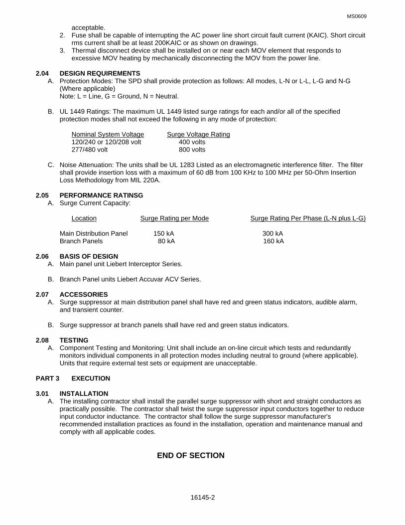
MS0609
16145-2
acceptable. 2. Fuse shall be capable of interrupting the AC power line short circuit fault current (KAIC). Short circuit rms current shall be at least 200KAIC or as shown on drawings. 3. Thermal disconnect device shall be installed on or near each MOV element that responds to excessive MOV heating by mechanically disconnecting the MOV from the power line. 2.04 DESIGN REQUIREMENTS A. Protection Modes: The SPD shall provide protection as follows: All modes, L-N or L-L, L-G and N-G
(Where applicable) Note: L = Line, G = Ground, N = Neutral. B. UL 1449 Ratings: The maximum UL 1449 listed surge ratings for each and/or all of the specified
protection modes shall not exceed the following in any mode of protection: Nominal System Voltage Surge Voltage Rating
120/240 or 120/208 volt 400 volts 277/480 volt 800 volts C. Noise Attenuation: The units shall be UL 1283 Listed as an electromagnetic interference filter. The filter
shall provide insertion loss with a maximum of 60 dB from 100 KHz to 100 MHz per 50-Ohm Insertion Loss Methodology from MIL 220A.
2.05 PERFORMANCE RATINSG A. Surge Current Capacity: Location Surge Rating per Mode Surge Rating Per Phase (L-N plus L-G) Main Distribution Panel 150 kA 300 kA Branch Panels 80 kA 160 kA
2.06 BASIS OF DESIGN A. Main panel unit Liebert Interceptor Series. B. Branch Panel units Liebert Accuvar ACV Series.
2.07 ACCESSORIES A. Surge suppressor at main distribution panel shall have red and green status indicators, audible alarm,
and transient counter. B. Surge suppressor at branch panels shall have red and green status indicators. 2.08 TESTING A. Component Testing and Monitoring: Unit shall include an on-line circuit which tests and redundantly
monitors individual components in all protection modes including neutral to ground (where applicable). Units that require external test sets or equipment are unacceptable.
PART 3 EXECUTION 3.01 INSTALLATION A. The installing contractor shall install the parallel surge suppressor with short and straight conductors as
practically possible. The contractor shall twist the surge suppressor input conductors together to reduce input conductor inductance. The contractor shall follow the surge suppressor manufacturer's recommended installation practices as found in the installation, operation and maintenance manual and comply with all applicable codes.
END OF SECTION

MS0109
16170-1
SECTION 16170: GROUNDING AND BONDING PART 1 GENERAL 1.01 RELATED SPECIFICATION SECTIONS: A. Section 01000 – GENERAL REQUIREMENTS 1.02 SECTION INCLUDES
A. Grounding electrodes and conductors. B. Equipment grounding conductors. C. Bonding. 1.03 REFERENCES A. ANSI/NFPA 70 - National Electrical Code. 1.04 GROUNDING ELECTRODE SYSTEM A. Rod electrode. 1.05 PERFORMANCE REQUIREMENTS
A. Grounding System Resistance: 25 ohms except as noted on the drawings. B. All grounding and bonding shall comply with NEC 2005, section 250.
1.06 SUBMITTALS A. Submit under provisions of Section 01300. B. Product Data: Provide data for grounding electrodes and connections. C. Test Reports: Indicate overall resistance to ground. D. Manufacturer's Instructions: Include instructions for storage, handling, protection, examination,
preparation and installation of exothermic connectors. 1.07 REGULATORY REQUIREMENTS A. Conform to requirements of ANSI/NFPA 70. B. Furnish products listed and classified by Underwriters Laboratories, Inc. as suitable for purpose specified
and shown. PART 2 PRODUCTS 2.01 ROD ELECTRODE A. Material: Copper. B. Diameter: 3/4 inch. C. Length: 20 feet. 2.02 MECHANICAL CONNECTORS A. Material: Bronze. 2.03 WIRE A. Material: Stranded copper. B. Foundation Electrodes: 2 AWG. C. Grounding Electrode Conductor: Size to meet NFPA 70 requirements.

MS0109
16170-2
PART 3 EXECUTION 3.01 EXAMINATION A. Verify that final backfill and compaction has been completed before driving rod electrodes. 3.02 INSTALLATION A. Install Products in accordance with manufacturer's instructions. B. Install rod electrodes at locations indicated. Install additional rod electrodes as required to achieve
specified resistance to ground. C. Unless otherwise indicated, ground rod shall be driven into ground until top of rod is approximately 1foot
below finished grade. D. Install 2 AWG bare copper wire in foundation footing where indicated. E. Provide bonding to meet Regulatory Requirements. F. Equipment Grounding Conductor: Provide separate, insulated conductor within each feeder and branch
circuit raceway. Terminate each end on suitable lug, bus, or bushing. G. Bond all separately derived systems (SDS) including foundation reinforcement steel and building steel to
main electrical ground. Communication, fire, video, etc., systems are considered SDS. 3.03 FIELD QUALITY CONTROL: A. Inspect grounding and bonding system conductors and connections for tightness and proper installation. B. Use suitable test instrument to measure resistance to ground of system. Perform testing in accordance
with test instrument manufacturer's recommendations using the fall-of-potential method. Provide full fall of potential graph and submit as test result. Resistance shall not exceed 25 Ohms.
END OF SECTION

MS0109
16190-1
SECTION 16190: SUPPORTING DEVICES PART 1 GENERAL 1.01 RELATED SPECIFICATION SECTIONS: A. Section 01000 – GENERAL REQUIREMENTS 1.02 SECTION INCLUDES A. Conduit and equipment supports. B. Anchors and fasteners. 1.03 REFERENCES A. NECA - National Contractors Association. B. ANSI/NFPA 70 - National Electrical Code. 1.04 REGULATORY REQUIREMENTS A. Conform to requirements of ANSI/NFPA 70. B. Furnish products listed and classified by Underwriters Laboratories, Inc. or testing firm acceptable to
authority having jurisdiction as suitable for purpose specified and shown. PART 2 PRODUCTS 2.01 PRODUCT REQUIREMENTS A. Materials and Finishes: Provide adequate corrosion resistance. B. Provide materials, sizes, and types of anchors, fasteners and supports to carry the loads of equipment
and conduit. Consider weight of wire in conduit when selecting products. C. Anchors and Fasteners: 1. Concrete Structural Elements: Use expansion anchors 2. Steel Structural Elements: Use beam clamps, spring steel clips. 3. Concrete Surfaces: Use self-drilling anchors and expansion anchors. 4. Hollow Masonry, Plaster, and Gypsum Board Partitions: Use toggle bolts and hollow wall fasteners. 5. Solid Masonry Walls: Use expansion anchors. 6. Sheet Metal: Use sheet metal screws. PART 3 EXECUTION 3.01 INSTALLATION A. Install products in accordance with manufacturer's instructions. B. Provide anchors, fasteners, and supports in accordance with NECA "Standard of Installation". C. Do not fasten supports to pipes, ducts, mechanical equipment, and conduit. D. Obtain permission from Architect/Engineer before using powder-actuated anchors. E. Obtain permission from Architect/Engineer before drilling or cutting structural members. F. Fabricate supports from structural steel or steel channel. Rigidly weld members or use hexagon head
bolts to present neat appearance with adequate strength and rigidity. Use spring lock washers under all nuts.
G. Install surface-mounted cabinets and panelboards with minimum of four anchors.

MS0109
16190-2
H. In wet and damp locations use steel channel supports to stand cabinets and panelboards one inch (25
mm) off wall.
END OF SECTION

MS0109
16195-1
SECTION 16195: ELECTRICAL IDENTIFICATION PART 1 GENERAL 1.01 RELATED SPECIFICATION SECTIONS: A. Section 01000 – GENERAL REQUIREMENTS 1.02 SECTION INCLUDES A. Nameplates and labels. B. Wire and cable markers. C. Conduit markers. 1.03 REFERENCES A. ANSI/NFPA 70 - National Electrical Code. 1.04 REGULATORY REQUIREMENTS A. Conform to requirements of ANSI/NFPA 70. B. Furnish products listed and classified by Underwriters Laboratories, Inc. or testing firm acceptable to
authority having jurisdiction as suitable for purpose specified and shown. PART 2 PRODUCTS 2.01 NAMEPLATES AND LABELS A. Nameplates: Engraved three-layer laminated plastic, white letters on black background. B. Locations: Each electrical distribution and control equipment enclosure. Example: PANEL A. C. Letter Size: 1. Use 1/4-inch letters for identifying individual equipment and loads. 2. Use 1/2-inch letters for identifying grouped equipment and loads. 2.02 WIRE MARKERS A. Description: Tape type wire markers. B. Locations: Each conductor at panelboard gutters, pull boxes, outlet and junction boxes, and each load
connection. C. Legend: 1. Power and Lighting Circuits: Branch circuit or feeder number indicated on drawings. 2. Control Circuits: Control wire number indicated on schematic and interconnection diagrams and
equipment manufacturer's shop drawings for control wiring. 2.03 CONDUIT MARKERS A. Description: Tape. B. Location: Furnish markers for each conduit longer than 6 feet. C. Spacing: 20 feet on center. D. Color: 1. 208 Volt System: Gray. 2. Fire Alarm System: Red. 3. Telephone System: Blue. 4. Low Voltage System: Black.

MS0109
16195-2
2.04 UNDERGROUND WARNING TAPE A. Description: 6-inch wide plastic tape, colored red with suitable warning legend describing buried
electrical lines; Style No. 210 ELE as manufactured by Seton. PART 3 EXECUTION 3.01 PREPARATION A. Degrease and clean surfaces to receive nameplates and labels. 3.02 APPLICATION A. Install nameplate and labels parallel to equipment lines. B. Secure nameplate to equipment front using screws, rivets, or adhesive. C. Secure nameplate to inside surface of door on panelboard that is recessed in finished locations. D. Identify underground conduits using underground warning tape. Install one tape per trench at 3 inches
below finished grade.
END OF SECTION
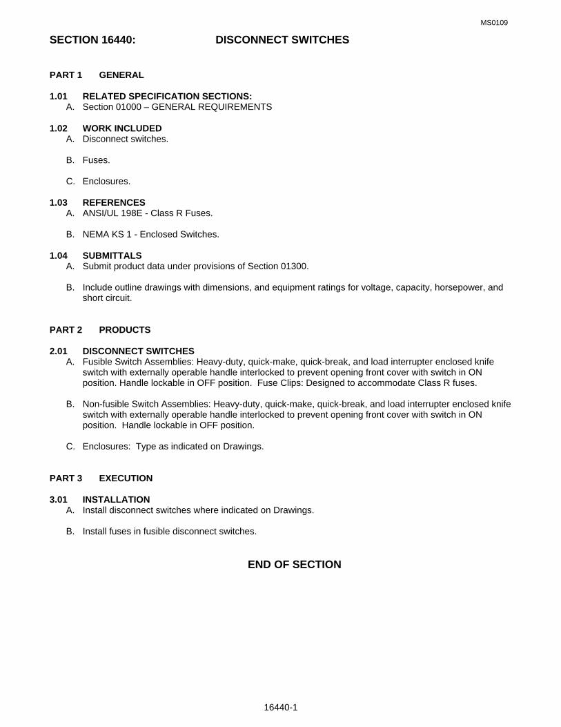
MS0109
16440-1
SECTION 16440: DISCONNECT SWITCHES PART 1 GENERAL 1.01 RELATED SPECIFICATION SECTIONS: A. Section 01000 – GENERAL REQUIREMENTS 1.02 WORK INCLUDED A. Disconnect switches. B. Fuses. C. Enclosures. 1.03 REFERENCES A. ANSI/UL 198E - Class R Fuses. B. NEMA KS 1 - Enclosed Switches. 1.04 SUBMITTALS A. Submit product data under provisions of Section 01300. B. Include outline drawings with dimensions, and equipment ratings for voltage, capacity, horsepower, and
short circuit. PART 2 PRODUCTS 2.01 DISCONNECT SWITCHES A. Fusible Switch Assemblies: Heavy-duty, quick-make, quick-break, and load interrupter enclosed knife
switch with externally operable handle interlocked to prevent opening front cover with switch in ON position. Handle lockable in OFF position. Fuse Clips: Designed to accommodate Class R fuses.
B. Non-fusible Switch Assemblies: Heavy-duty, quick-make, quick-break, and load interrupter enclosed knife
switch with externally operable handle interlocked to prevent opening front cover with switch in ON position. Handle lockable in OFF position.
C. Enclosures: Type as indicated on Drawings. PART 3 EXECUTION 3.01 INSTALLATION A. Install disconnect switches where indicated on Drawings. B. Install fuses in fusible disconnect switches. END OF SECTION

MS0109
16450-1
SECTION 16450: SECONDARY GROUNDING PART 1 GENERAL 1.01 RELATED SPECIFICATION SECTIONS: A. Section 01000 – GENERAL REQUIREMENTS 1.02 WORK INCLUDED A. Power system grounding. B. Communication system grounding. C. Electrical equipment and raceway grounding and bonding. 1.03 SYSTEM DESCRIPTION A. Ground the electrical service system neutral at service entrance equipment to grounding electrodes. B. Provide communications system ground rod at point of service entrance and connect to the building
ground at the service entrance with 1/0 bare copper conductor. C. Bond together system neutrals, service equipment enclosures, exposed non-current carrying metal parts
of electrical equipment, metal raceway systems, grounding conductor in raceways and cables, receptacle ground connectors, and plumbing systems.
1.04 SUBMITTALS A. Submit shop drawings under provisions of Section 01300. B. Indicate the layout of ground ring, location of system grounding electrode connections, and routing of
grounding electrode conductor. PART 2 PRODUCTS 2.01 MATERIALS A. Ground Rods: Copper-encased steel, 3/4-inch (19 mm) diameter, minimum length 20 feet. B. Ground Conductor: 1/0 bare copper. PART 3 EXECUTION 3.01 INSTALLATION A. Provide a separate insulated equipment-grounding conductor in feeder and branch circuits. Terminate
each end on a grounding lug, bus, or bushing. B. Provide grounding and bonding at the pad-mounted transformer. 3.02 FIELD QUALITY CONTROL A. Inspect grounding and bonding system conductors and connections for tightness and proper installation. B. Use suitable test instrument to measure resistance to ground of system. Perform testing in accordance
with test instrument manufacturer's recommendations using the fall-of-potential method. Provide full-fall of-potential graph and submit as test result. Resistance shall not exceed 10 ohms.
END OF SECTION

262923‐1
SECTION 26 29 23: VARIABLE FREQUENCY DRIVE SYSTEMS UNDER 600 VOLTS PART 1 GENERAL 1.01 REFERENCES The publications listed below form a part of this specification to the extent referenced. The publications
are referred to within the text by the basic designation only. A. INSTITUTE OF ELECTRICAL AND ELECTRONICS ENGINEERS (IEEE) 1. IEEE 519(1992; R 1993; Errata 2004) Recommended Practices and Requirements for Harmonic
Control in Electrical Power Systems 2. IEEE C62.41.1(2002; R 2008) Guide on the Surges Environment in Low-Voltage (1000 V and Less)
AC Power Circuits 3. IEEE C62.41.2(2002) Recommended Practice on Characterization of Surges in Low-Voltage (1000
V and Less) AC Power Circuits B. NATIONAL ELECTRICAL MANUFACTURERS ASSOCIATION (NEMA) 1. NEMA 250(2008) Enclosures for Electrical Equipment (1000 Volts Maximum) 2. NEMA ICS 1(2000; R 2005; R 2008) Standard for Industrial Control and Systems: General
Requirements 3. NEMA ICS 3.1(1997; R 2003) Handling, Storage and Installation Guide for AC General-Purpose
Medium-Voltage Contactors and Class E Controllers, 50 and 60 Hertz 4. NEMA ICS 6(1993; R 2001; R 2006) Standard for Enclosures 5. NEMA ICS 7(2006) Industrial Control and Systems: Adjustable-Speed Drives C. NATIONAL FIRE PROTECTION ASSOCIATION (NFPA) 1. NFPA 70(2008; AMD 1 2008) National Electrical Code D. U.S. DEPARTMENT OF DEFENSE (DOD) 1. MIL-STD-461(2007; Rev F) Requirements for the Control of Electromagnetic Interference
Characteristics of Subsystems and Equipment E. U.S. NATIONAL ARCHIVES AND RECORDS ADMINISTRATION (NARA) 1. 47 CFR 15Radio Frequency Devices F. UNDERWRITERS LABORATORIES (UL) 1. UL 489(2009) Molded-Case Circuit Breakers, Molded-Case Switches and Circuit-Breaker
Enclosures 2. UL 508C(2002; R2003 thru 2008) Standard for Power Conversion Equipment 1.02 RELATED REQUIREMENTS Division 16 specifications. 1.03 SYSTEM DESCRIPTION A. Performance Requirements 1. Electromagnetic Interference Suppression Computing devices, as defined by 47 CFR 15, MIL-STD-461 rules and regulations, shall be certified
to comply with the requirements for class A computing devices and labeled as set forth in part 15. 2. Electromechanical and Electrical Components Electrical and electromechanical components of the Variable Frequency Drive (VFD) shall not
cause electromagnetic interference to adjacent electrical or electromechanical equipment while in operation.
B. Electrical Requirements 1. Power Line Surge Protection

262923‐2
IEEE C62.41.1 and IEEE C62.41.2, IEEE 519 Control panel shall have surge protection, included within the panel to protect the unit from damaging transient voltage surges. Surge arrestor shall be mounted near the incoming power source and properly wired to all three phases and ground. Fuses shall not be used for surge protection.
2. Sensor and Control Wiring Surge Protection I/O functions as specified shall be protected against surges induced on control and sensor wiring
installed outdoors and as shown. The inputs and outputs shall be tested in both normal mode and common mode using the following two waveforms:
a. A 10 microsecond by 1000 microsecond waveform with a peak voltage of 1500 volts and a peak current of 60 amperes.
b. An 8 microsecond by 20 microsecond waveform with a peak voltage of 1000 volts and a peak current of 500 amperes.
1.04 SUBMITTALS A. Submit under provisions of Section 01300. B. Shop Drawings: Indicate dimensions and components for each luminary, which is not a standard
product of the manufacturer. Provide signed, sealed and dated drawing by a currently registered professional engineer in the state of Florida certifying that the system meets or exceeds the required design conditions.
C. Product Data: Provide dimensions, ratings, and performance data. D. Manufacturer's Instructions: Indicate application conditions and limitations of use stipulated by product
testing agency specified under "Regulatory Requirements". E. Manufacturer's Instructions: Include instructions for storage, handling, protection, examination,
preparation, installation, and starting of product. F. Specific submittal requirements given below: Shop Drawings Schematic diagrams Interconnecting diagrams Installation drawings Submit drawings for government approval prior to equipment construction or integration.
Modifications to original drawings made during installation shall be immediately recorded for inclusion into the as-built drawings.
Product Data Variable frequency drives Wires and cables Equipment schedule Include data indicating compatibility with motors being driven. Test Reports VFD Test Performance Verification Tests Endurance Test Manufacturer's Instructions Installation instructions Manufacturer's Field Reports VFD Factory Test Plan Factory test results Operation and Maintenance Data Variable frequency drives

262923‐3
Provide service and maintenance information including preventive maintenance, assembly, and disassembly procedures. Include electrical drawings from electrical general sections. Submit additional information necessary to provide complete operation, repair, and maintenance information, detailed to the smallest replaceable unit. Include copies of as-built submittals. Provide routine preventative maintenance instructions, and equipment required. Provide instructions on how to modify program settings, and modify the control program. Provide instructions on drive adjustment, trouble-shooting, and configuration. Provide instructions on process tuning and system calibration.
1.05 QUALITY ASSURANCE A. Schematic Diagrams Show circuits and device elements for each replaceable module. Schematic diagrams of printed circuit
boards are permitted to group functional assemblies as devices, provided that sufficient information is provided for government maintenance personnel to verify proper operation of the functional assemblies.
B. Interconnecting Diagrams Show interconnections between equipment assemblies, and external interfaces, including power and
signal conductors. Include for enclosures and external devices. C. Installation Drawings Show floor plan of each site, with V.F.D.'s and motors indicated. Indicate ventilation requirements,
adequate clearances, and cable routes. D. Equipment Schedule Provide schedule of equipment supplied. Schedule shall provide a cross reference between
manufacturer data and identifiers indicated in shop drawings. Schedule shall include the total quantity of each item of equipment supplied. For complete assemblies, such as VFD's, provide the serial numbers of each assembly, and a sub-schedule of components within the assembly. Provide recommended spare parts listing for each assembly or component.
E. Installation instructions Provide installation instructions issued by the manufacturer of the equipment, including notes and
recommendations, prior to shipment to the site. Provide operation instructions prior to acceptance testing.
F. Factory Test Results Document test results and submit to government within 7 working days after completion of test. 1.06 DELIVERY AND STORAGE Equipment delivered and placed in storage shall be stored with protection from the weather, humidity
and temperature variations, dirt and dust, or other contaminants. 1.07 WARRANTY The complete system shall be warranted by the manufacturer for a period of one year, or the contracted
period of any extended warrantee agreed upon by the contractor and the Government, after successful completion of the acceptance test. Any component failing to perform its function as specified and documented shall be repaired or replaced by the contractor at no additional cost to the Government. Items repaired or replaced shall be warranted for an additional period of at least one year from the date that it becomes functional again, as specified in the FAR CLAUSE 52.246-21.
1.08 MAINTENANCE A. Spare Parts Manufacturers provide spare parts in accordance with recommended spare parts list.

262923‐4
B. Maintenance Support During the warranty period, the Contractor shall provide on-site, on-call maintenance services by
Contractor's personnel on the following basis: The service shall be on a per-call basis with 36 hour response. Contractor shall support the maintenance of all hardware and software of the system. Various personnel of different expertise shall be sent on-site depending on the nature of the maintenance service required. Costs shall include travel, local transportation, living expenses, and labor rates of the service personnel while responding to the service request. The provisions of this Section are not in lieu of, nor relieve the Contractor of, warranty responsibilities covered in this specification. Should the result of the service request be the uncovering of a system defect covered under the warranty provisions, all costs for the call, including the labor necessary to identify the defect, shall be borne by the Contractor.
PART 2 PRODUCTS 2.01 VARIABLE FREQUENCY DRIVES (VFD) Provide frequency drive to control the speed of induction motor(s). The VFD shall include the following
minimum functions, features and ratings. 1. Input circuit breaker per UL 489 with a minimum of 10,000 amps symmetrical interrupting capacity
and door interlocked external operator. 2. A converter stage per UL 508C shall change fixed voltage, fixed frequency, ac line power to a fixed
dc voltage. The converter shall utilize a full wave bridge design incorporating diode rectifiers. Silicon Controlled Rectifiers (SCR) are not acceptable. The converter shall be insensitive to three phase rotation of the ac line and shall not cause displacement power factor of less than .95 lagging under any speed and load condition.
3. An inverter stage shall change fixed dc voltage to variable frequency, variable voltage, ac for application to a standard NEMA design B squirrel cage motor. The inverter shall be switched in a manner to produce a sine coded pulse width modulated (PWM) output waveform.
4. The VFD shall be capable of supplying 120 percent of rated full load current for one minute at maximum ambient temperature.
5. The VFD shall be designed to operate from a 460 volt, + or - 10 percent, three phase, 60 Hz supply, and control motors with a corresponding voltage rating.
6. Acceleration and deceleration time shall be independently adjustable from one second to 60 seconds.
7. Adjustable full-time current limiting shall limit the current to a preset value which shall not exceed 120 percent of the controller rated current. The current limiting action shall maintain the V/Hz ratio constant so that variable torque can be maintained. Short time starting override shall allow starting current to reach 175 percent of controller rated current to maximum starting torque.
8. The controllers shall be capable of producing an output frequency over the range of 3 Hz to 60 Hz (20 to one speed range), without low speed cogging. Over frequency protection shall be included such that a failure in the controller electronic circuitry shall not cause frequency to exceed 110 percent of the maximum controller output frequency selected.
9. Minimum and maximum output frequency shall be adjustable over the following ranges: 1) Minimum frequency 3 Hz to 50 percent of maximum selected frequency; 2) Maximum frequency 40 Hz to 60 Hz.
10. The controller efficiency at any speed shall not be less than 96 percent. 11. The controllers shall be capable of being restarted into a motor coasting in the forward direction
without tripping.

262923‐5
12.Protection of power semiconductor components shall be accomplished without the use of fast acting semiconductor output fuses. Subjecting the controllers to any of the following conditions shall not result in component failure or the need for fuse replacement:
a. Short circuit at controller output b. Ground fault at controller output c. Open circuit at controller output d. Input undervoltage e. Input overvoltage f. Loss of input phase g. AC line switching transients h. Instantaneous overload i. Sustained overload exceeding 115 percent of controller rated current j. Over temperature k. Phase reversal 13. Solid state motor overload protection shall be included such that current exceeding an adjustable
threshold shall activate a 60 second timing circuit. Should current remain above the threshold continuously for the timing period, the controller will automatically shut down.
14. A slip compensation circuit shall be included which will sense changing motor load conditions and adjust output frequency to provide speed regulation of NEMA B motors to within + / - 0.5 percent of maximum speed without the necessity of a tachometer generator.
15. The VFD shall be factory set for manual restart after the first protective circuit trip for malfunction (overcurrent,undervoltage, overvoltage or overtemperature) or an interruption of power. The VFD shall be capable of being set for automatic restart after a selected time delay. If the drive faults again within a specified time period (adjustable 0-60 seconds), a manual restart will be required.
16. The VFD shall include external fault reset capability. All the necessary logic to accept an external fault reset contact shall be included.
17. Provide critical speed lockout circuitry to prevent operating at frequencies with critical harmonics that cause resonant vibrations. The VFD shall have a minimum of three user selectable bandwidths.
18. Provide the following operator control and monitoring devices mounted on the front panel of the VFD:
a. Manual speed potentiometer. b. Hand-Off-Auto ( HOA ) switch. c. Power on light. d. Drive run power light. e. Local display. 19. Provide properly sized NEMA rated by-pass and isolation contactors to enable operation of motor in
the event of VFD failure. Mechanical and electrical interlocks shall be installed between the by-pass and isolation contactors. Provide a selector switch and transfer delay timer.
2.02 ENCLOSURES Provide equipment enclosures conforming to NEMA 250, NEMA ICS 7, NEMA ICS 6. 2.03 WIRES AND CABLES All wires and cables shall conform to NEMA 250, NEMA ICS 7, NFPA 70. 2.04 NAMEPLATES

262923‐6
Nameplates external to NEMA enclosures shall conform with the requirements of Section 16000 BASIC ELECTRICAL REQUIREMENTS. Nameplates internal to enclosures shall be manufacturer's standard, with the exception that they must be permanent.
2.05 SOURCE QUALITY CONTROL A. VFD Factory Test Plan To ensure quality, each VFD shall be subject to a series of in-plant quality control inspections before
approval for shipment from the manufacturer's facilities. Provide test plans and test reports. PART 3 EXECUTION 3.01 INSTALLATION Per NEMA ICS 3.1, install equipment in accordance with the approved manufacturer's printed
installation drawings, instructions, wiring diagrams, and as indicated on project drawings and the approved shop drawings. A field representative of the drive manufacturer shall supervise the installation of all equipment, and wiring.
3.02 FIELD QUALITY CONTROL Specified products shall be tested as a system for conformance to specification requirements prior to
scheduling the acceptance tests. Contractor shall conduct performance verification tests in the presence of Government representative, observing and documenting complete compliance of the system to the specifications. Contractor shall submit a signed copy of the test results, certifying proper system operation before scheduling tests.
A. VFD Test A proposed test plan shall be submitted to the contracting officer at least 28 calendar days prior to
proposed testing for approval. The tests shall conform to NEMA ICS 1, NEMA ICS 7, and all manufacturer's safety regulations. The Government reserves the right to witness all tests and review any documentation. The contractor shall inform the Government at least 14 working days prior to the dates of testing. Contractor shall provide video tapes, if available, of all training provided to the Government for subsequent use in training new personnel. All training aids, texts, and expendable support material for a self-sufficient presentation shall be provided, the amount of which to be determined by the contracting officer.
B. Performance Verification Tests "Performance Verification Test" plan shall provide the step by step procedure required to establish
formal verification of the performance of the VFD. Compliance with the specification requirements shall be verified by inspections, review of critical data, demonstrations, and tests. The Government reserves the right to witness all tests, review data, and request other such additional inspections and repeat tests as necessary to ensure that the system and provided services conform to the stated requirements. The contractor shall inform the Government 14 calendar days prior to the date the test is to be conducted.
C. Endurance Test Immediately upon completion of the performance verification test, the endurance test shall commence.
The system shall be operated at varying rates for not less than 192 consecutive hours, at an average effectiveness level of .9998, to demonstrate proper functioning of the complete PCS. Continue the test on a day-to-day basis until performance standard is met. During the endurance test, the contractor shall not be allowed in the building. The system shall respond as designed.
3.03 DEMONSTRATION A. Training

262923‐7
Coordinate training requirements with the Contracting Officer. 1. Instructions to Government Personnel Provide the services of competent instructors who will give full instruction to designated personnel
in operation, maintenance, calibration, configuration, and programming of the complete control system. Orient the training specifically to the system installed. Instructors shall be thoroughly familiar with the subject matter they are to teach. The Government personnel designated to attend the training will have a high school education or equivalent. The number of training days of instruction furnished shall be as specified. A training day is defined as eight hours of instruction, including two 15-minute breaks and excluding lunch time; Monday through Friday. Provide a training manual for each student at each training phase which describes in detail the material included in each training program. Provide one additional copy for archiving. Provide equipment and materials required for classroom training. Provide a list of additional related courses, and offers, noting any courses recommended. List each training course individually by name, including duration, approximate cost per person, and location of course. Unused copies of training manuals shall be turned over to the Government at the end of last training session.
2. Operating Personnel Training Program Provide one 2 hour training session at the site at a time and place mutually agreeable between the
Contractor and the Government. Provide session to train 4 operation personnel in the functional operations of the system and the procedures that personnel will follow in system operation. This training shall include:
a. System overview b. General theory of operation c. System operation d. Alarm formats e. Failure recovery procedures f. Troubleshooting 3. Engineering/Maintenance Personnel Training Accomplish the training program as specified. Training shall be conducted on site at a location
designated by the Government. Provide a one day training session to train 4 engineering personnel in the functional operations of the system. This training shall include:
a. System overview b. General theory of operation c. System operation d. System configuration e. Alarm formats f. Failure recovery procedures g. Troubleshooting and repair h. Maintenance and calibration i. System programming and configuration
END OF SECTION