Embed Size (px)
Citation preview

SPECIFICATIONS FOR LCD MODULE
CUSTOMER 华勤
MODEL TD-T145T2G2360-5
CUSTOMER APPROVED
ORGANIZED BY CHECKED BY APPROVED BY
闵江波 行亚鹏 吴石梁
□ APPROVAL FOR SPECIFICATIONS ONLY ■ APPROVAL FOR SPECIFICATIONS AND SAMPLE
广东省惠州市江北云山东路 21 号 TCL 工业区 9号工业厂房
Building 9, TCL Industrial Park, Yunshan East Road, Jiangbei, Huizhou, Guangdong, China.
电话/Tel: 0752-5808888 传真/Fax: 0752-5808877 邮编/P.C.: 516003
http://www.tcldisplay.com

TD-T145T2G2360-5 SPEC Ver. A0 2/19
Contents
1. Contents……………………………………………………………………………………….2
2. Revision History……………………………………………………………………………..3
3. Numbering System………………………………………………………………..……....4
4. Features………………………………………………………………………………………..5
5. Mechanical Specifications………………………………………………………………..5
6. Absolute Maximum Ratings……………………………………………………………..5
7. Electrical Specification…………………………………………………………………….5
8. Optical Specification……………………………………………………………………….6
9. Viewing Modes……………………………………………………………………………….6
10. Electro-Optical Characteristics Test Method……………………………………….7
11. Outline Dimension………………………………………………………………………….9
12. Block Diagram………………………………………………………………………………10
13. Table of Pin Assignment…………………………………………………………………11
14. Command/AC Timing…………………………………………………………………….12
15. Inspection Criteria…..…………………………………………………………………….14
16. Reliability……………….…………………………………………………………………….16
17. For Safety…………………………………………………………………………………….17
18. Packaging…………………………………………………………………………………….18
TD-T145T2G2360-5 SPEC Ver. A0 3/19
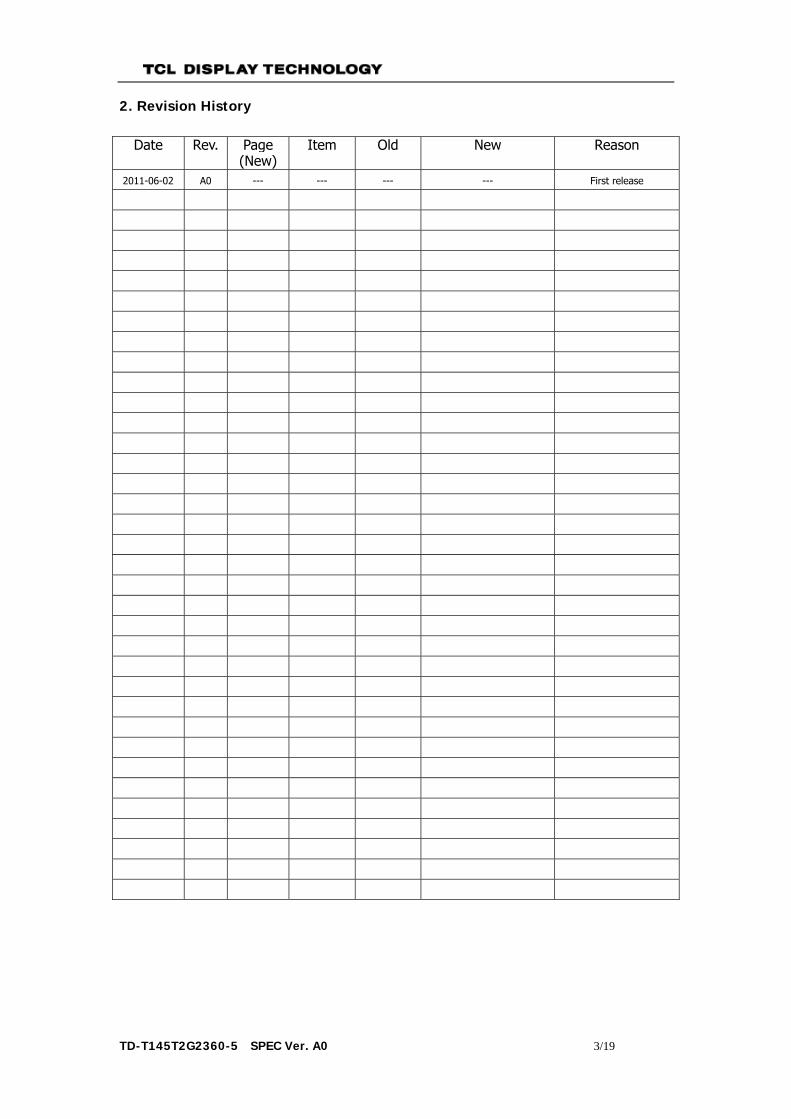
2. Revision History
Date Rev. Page (New)
Item Old New Reason
2011-06-02 A0 --- --- --- --- First release
TD-T145T2G2360-5 SPEC Ver. A0 4/19
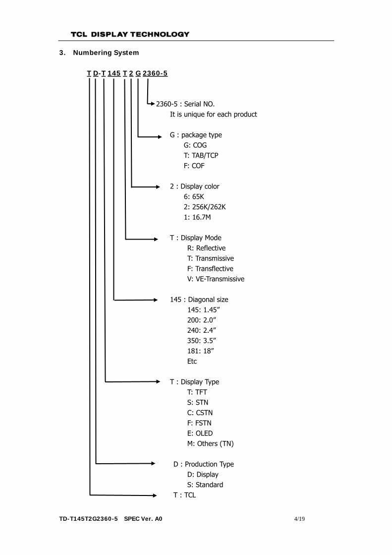
3. Numbering System
T D-T 145 T 2 G 2360-5
2360-5 : Serial NO. It is unique for each product
G : package type G: COG T: TAB/TCP F: COF 2 : Display color 6: 65K 2: 256K/262K 1: 16.7M T : Display Mode R: Reflective T: Transmissive F: Transflective V: VE-Transmissive 145 : Diagonal size 145: 1.45” 200: 2.0” 240: 2.4” 350: 3.5” 181: 18” Etc T : Display Type T: TFT S: STN C: CSTN F: FSTN E: OLED M: Others (TN) D : Production Type D: Display S: Standard T : TCL
TD-T145T2G2360-5 SPEC Ver. A0 5/19
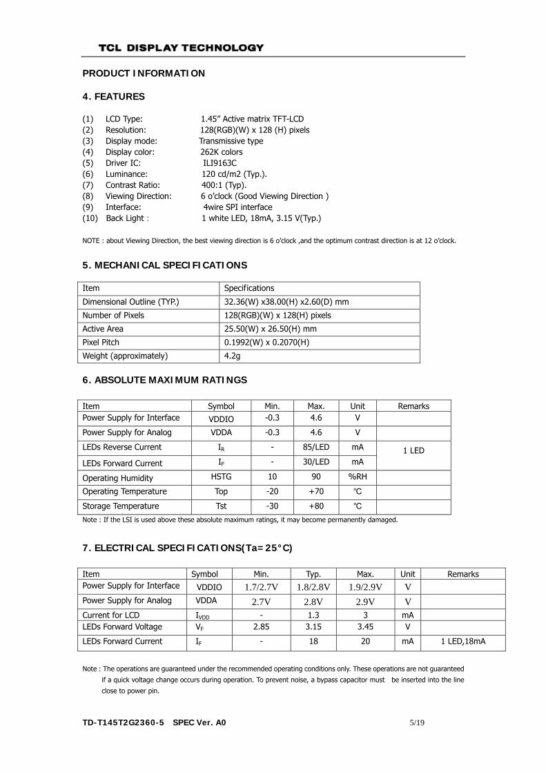
PRODUCT INFORMATION 4. FEATURES
(1) LCD Type: 1.45” Active matrix TFT-LCD (2) Resolution: 128(RGB)(W) x 128 (H) pixels (3) Display mode: Transmissive type (4) Display color: 262K colors (5) Driver IC: ILI9163C (6) Luminance: 120 cd/m2 (Typ.). (7) Contrast Ratio: 400:1 (Typ). (8) Viewing Direction: 6 o’clock (Good Viewing Direction ) (9) Interface: 4wire SPI interface (10) Back Light: 1 white LED, 18mA, 3.15 V(Typ.)
NOTE : about Viewing Direction, the best viewing direction is 6 o’clock ,and the optimum contrast direction is at 12 o’clock.
5. MECHANICAL SPECIFICATIONS
Item Specifications
Dimensional Outline (TYP.) 32.36(W) x38.00(H) x2.60(D) mm
Number of Pixels 128(RGB)(W) x 128(H) pixels
Active Area 25.50(W) x 26.50(H) mm
Pixel Pitch 0.1992(W) x 0.2070(H)
Weight (approximately) 4.2g
6. ABSOLUTE MAXIMUM RATINGS Item Symbol Min. Max. Unit Remarks Power Supply for Interface VDDIO -0.3 4.6 V
Power Supply for Analog VDDA -0.3 4.6 V
LEDs Reverse Current IR - 85/LED mA 1 LED LEDs Forward Current IF - 30/LED mA
Operating Humidity HSTG 10 90 %RH
Operating Temperature Top -20 +70 ℃
Storage Temperature Tst -30 +80 ℃
Note : If the LSI is used above these absolute maximum ratings, it may become permanently damaged.
7. ELECTRICAL SPECIFICATIONS(Ta=25°C) Item Symbol Min. Typ. Max. Unit Remarks Power Supply for Interface VDDIO 1.7/2.7V 1.8/2.8V 1.9/2.9V V Power Supply for Analog VDDA 2.7V 2.8V 2.9V V Current for LCD IVDD - 1.3 3 mA LEDs Forward Voltage VF 2.85 3.15 3.45 V
LEDs Forward Current IF - 18 20 mA 1 LED,18mA
Note : The operations are guaranteed under the recommended operating conditions only. These operations are not guaranteed
if a quick voltage change occurs during operation. To prevent noise, a bypass capacitor must be inserted into the line
close to power pin.

TD-T145T2G2360-5 SPEC Ver. A0 6/19
8. OPTICAL SPECIFICATIONS(Ta=25℃) Item Symbol Min. Typ. Max. Unit Remarks
Contrast Ratio C/R 350 400 - Fig.1
Brightness - 120 cd/m2 Full White Pattern
Brightness Uniformity 80 - - % Full White Pattern Fig.1,2
NTSC - 50 - %
Response Time Tr+Tf - 30 40 ms Fig.3
Color
Coordinate
RED Rx 0.5392 0.5792 0.6192
IBL=18mA
Ry 0.2821 0.3221 0.3621
GREEN Gx 0.2847 0.3247 0.3647
Gy 0.5387 0.5787 0.6187
BLUE Bx 0.1031 0.1431 0.1831
By 0.0335 0.0735 0.1135
WHITE Wx 0.2386 0.2786 0.3186
Wy 0.2525 0.2925 0.3325
view angle
θl 55 65 -
Degree
Fig.4
Center
(C/R>10) θr 55 65 -
θu 50 60 -
θd 40 50 - Note: 1. Contrast Ratio(CR) is defined mathematically as :
Average Surface Luminance with all pixels white(P1,P2,P3,P4,P5,P6,P7,P8,P9) Contrast Ratio =
Average Surface Luminance with all pixels black(P1,P2,P3,P4,P5,P6,P7,P8,P9) 2. Brightness is the LCM’s luminance from the surface with all pixels white. For more information see FIG 1. 3. Brightness Uniformity represents the consistency of LCM’s Brightness,signed forδBRIGHTNESS. δBRIGHTNESS is determined by measuring luminance at each test point 1 to 9,then got the maximum and mimimum luminance of 9 piont. For more information,see Fig 2.
Minimum Surface Luminance with all pixels white(P1,P2,P3,P4,P5,P6,P7,P8,P9) δBRIGHTNESS =
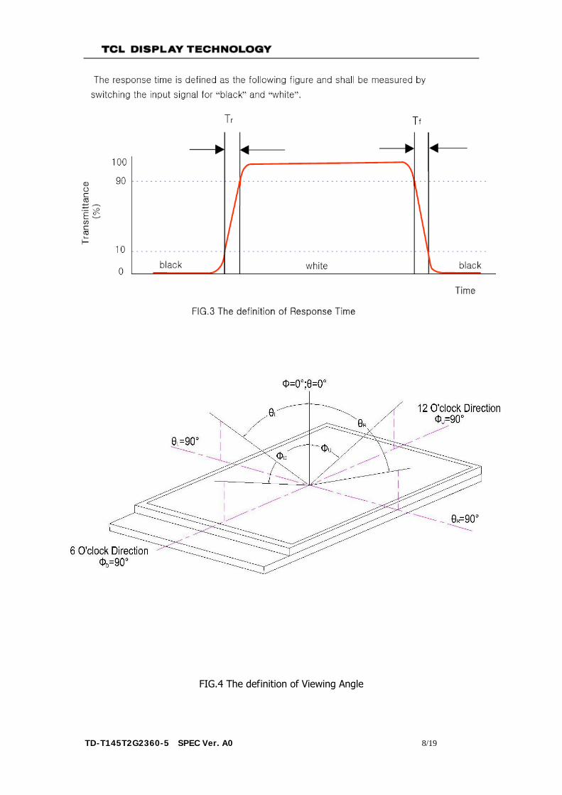
Maximum Surface Luminance with all pixels white(P1,P2,P3,P4,P5,P6,P7,P8,P9) 4. Response time is the time required for the display to transit from black to white (Rise Time, Tr) and from white to
black(Decay Time, Tf). For additional information see FIG 3. 5. Viewing angle is the angle at which the contrast ratio is greater than 10. The angles are determined for the horizontal
or x axis and the vertical or y axis with respect to the z axis which is normal to the LCD surface. For more information see FIG 4.
6. Optimum contrast is obtained by adjusting the LCD Threshold voltage (Vth& Vsat)
9. Viewing Modes

TD-T145T2G2360-5 SPEC Ver. A0 7/19
10. Electro-Optical Characteristics Test Method
P1-P9:
TD-T145T2G2360-5 SPEC Ver. A0 8/19
FIG.4 The definition of Viewing Angle

TD-T145T2G2360-5 SPEC Ver. A0 9/19
11. <Outline dimension> FIRS
T R
ELEA
SE(
base on 268-10E)
出货
图(出
货状
态)
弯折
参考
图
A

TD-T145T2G2360-5 SPEC Ver. A0 10/19
12. <Block diagram>
VDDA,VDDIO
LCDID_1,LCDID_2
ILI9163C
CS,RST,A0
SDA,SCL
LED+
TFT-LCD
128(H)RGB x 128(V)
LED-
GND

TD-T145T2G2360-5 SPEC Ver. A0 11/19
13. <Table of Pin Assignment >
PinNo. Signal I/O Discription
1 VDDIO P Power Supply for Logic Circuit (TYP1.8/ 2.8V) 2 VDDA P Power Supply for Analog Circuit (TYP 2.8V) 3 SDA I Data input in SPI mode 4 A0 I Register Select Signal(Low:command, High:data) 5 CS I Chip Select Signal (Low Active) 6 SCL I Synchronizing clock signal in SPI mode 7 GND P Ground 8 LCD_ID1 - Connected to VDD 9 RST I Reset Signal (Low Active) 10 GND P Ground 11 LED+ P Power Supply for LED(Anode) 12 LED- P Power Supply for LED(Cathode) 13 LCD_ID2 - Connected to GND
TD-T145T2G2360-5 SPEC Ver. A0 12/19
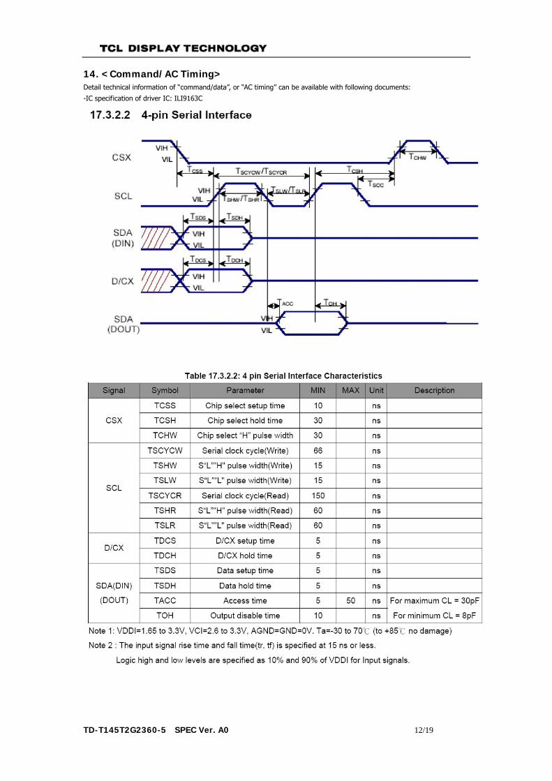
14. <Command/AC Timing> Detail technical information of “command/data”, or “AC timing” can be available with following documents:
-IC specification of driver IC: ILI9163C
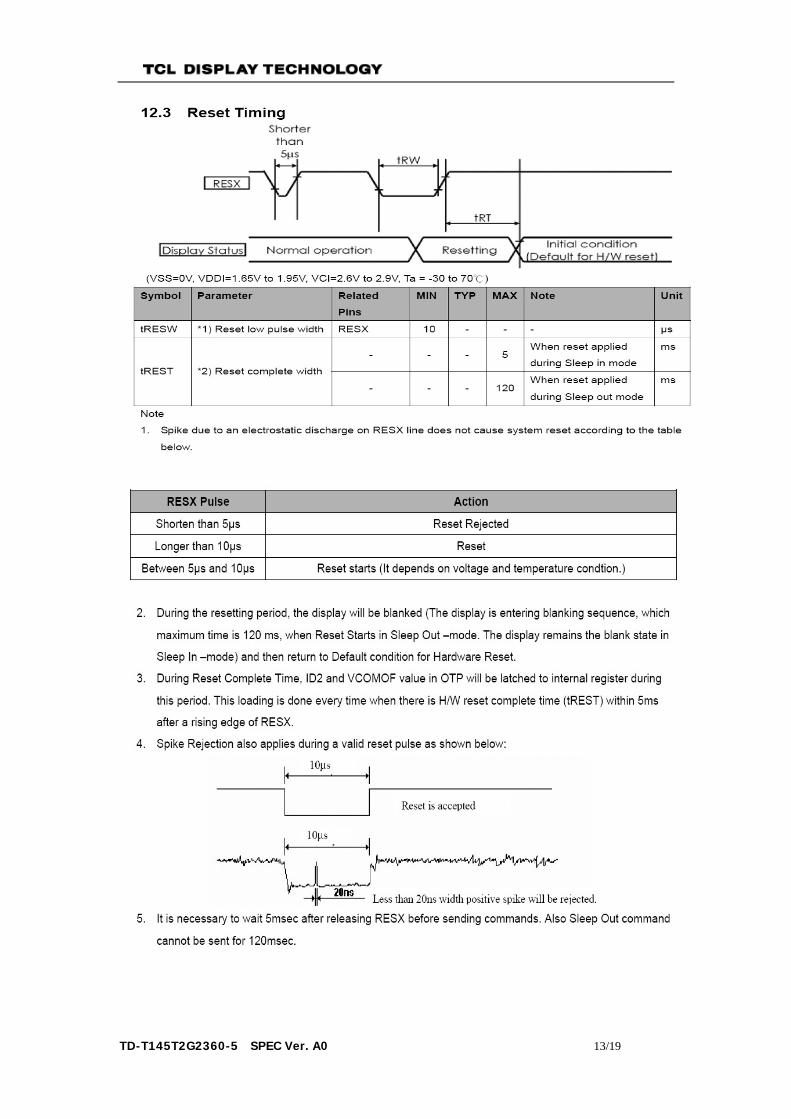
TD-T145T2G2360-5 SPEC Ver. A0 13/19

TD-T145T2G2360-5 SPEC Ver. A0 14/19
15. Inspection Criteria
Item NO.
Inspection Item Inspection Standard
Classification of defects
1
Electrical fuction Testing
1) No display 2) Missing line 3) No backlight 4) shadow 5) black/blue display 6) Irregular operating 7) visual angle is wrong
Major
2 Outline dimension All outline dimension beyond the drawing is not allowed
Major
3
White/Black spot ( in LCD or Backlight )
Φ(mm) acceptable Minor
Φ≤0.10 ignore
0.10 <Φ≤0.2 2
Φ>0.2 0
4 Dirt in POL as same as White/Black spot Minor
5 Dent at POL as same as White/Black spot Minor
6
Bubble in POL
Φ(mm) acceptable Minor Φ≤0.20 3
0.20 <Φ≤0.3 2
0.30 <Φ≤0.5 1
Φ>0.5 0
7 Color/bright/dark dot as same as White/Black spot Minor 8
Scratch / lines ( in LCD)
Width Length acceptable Minor W≤0.03 L<2.0 1
0.03 <W≤0.05 L≤1.0 1
W>0.08 ignore 0
ignore L>3.0 0
9 Scratch / lines in POL as same as White/Black spot Minor
10 Scratch / lines in BLU as same as White/Black spot Minor

TD-T145T2G2360-5 SPEC Ver. A0 15/19
If the acceptable number is ≥ 2 ,the interval between dots or lines must be ≥ 10mm .
11
LCD defect
Crack Unallowed Major
Pad break W>0.5mm, unallowed 。 Major
Con-Pad break
When a<1/2T(T=the thickness of single LCD): b≥1/2 PAD NG or c≥5mm NG When a≥1/2T: as same as PAD break
ca
tb
Minor
Break not in PAD
X≤1/8A; Y into the inspect area is unallawed; X≤1/8A, if Y not into the frame,Z ignore; X≤1/8A,Y≤1/2 Seal,Z≤1/2T is allawed X≤1/8A,Y>1/2 Seal, Z≤1/4T is allawed
Minor
Corner break
1)‘a’> 1MM unallowed2)‘b’> 1/4E unallowed (E = PAD long of short side)
Minor
Y
X
Z
W

TD-T145T2G2360-5 SPEC Ver. A0 16/19
16. Reliability Item NO.
TEST Item Condition Criterion
1 Humidity operating 60℃±3℃, 95%RH, 96 hrs · Placed 2 hours in normal temperature, then inspect the function and cosmetic after test.· After testing, cosmetic defects should not happen. · Polarizers may fail in humidity test, but only this failure is allowable.
2 Thermal shock test 25 ±℃ 3 (5min) ℃ → -40 ±℃ 3 (120min) ℃ → 25 ±℃ 3 (5min) ℃ → 70 ±℃ 3 (120min)℃ 24cycle

TD-T145T2G2360-5 SPEC Ver. A0 17/19
17. For Safety
LCD module is generally designed with precise parts to achieve light weighted thin mechanical
dimensions. In using our Modules, make certain that you fully understand and put into practice the warnings and
safety precautions detailed in Engineering Information No.EE-N001,"CAUTIONS AND INATRUCTIONNS FOR TCL DISPLAY TECHNOLOGY CO., LTD. LCD MODULES".
Refer to individual specifications and TECHNICAL DATA sheets (hereinafter called “TD”) for more detailed technical information.
1) SPECIAL PURPOSES a) TCL Display Technology’s Standard LCD modules have not been customized for operation in extreme environments or for use in applications where performance failures could be life-threatening or otherwise catastrophic. b) Since TCL Display Technology’s Standard LCD modules have not been designed for operation in extreme environments, they must never be used in devices that will be exposed to abnormally high levels of vibration or shock which exceed TCL Display Technology’s published specification limits. c) In addition, since TCL Display Technology’s Standard LCD modules have not been designed for use in applications where performance failures could be life-threatening or catastrophic, they must never be installed in aircraft navigation control systems (such as, but not limited to Traffic Collision Avoidance System and Air Traffic Indicator), in military defense or weapons systems, in critical industrial process-control systems (e.g., those involved in the production of nuclear energy), or in critical medical device or patient life-support systems. 2) DISASSEMBLING OR MODIFICATION
DO NOT DISASSEMBLE OR MODIFY the modules. It may damage sensitive parts inside LCD module, and may cause scratches or dust on the display. TCL Display Technology does not warrant the modules, if customer disassembled or modified it.
3) BREAKAGE OF LCD PANEL
DO NOT INGEST liquid crystal material, DO NOT INHALE this material, and DO NOT PERMIT this material with skin, if LCD panel is broken and liquid crystal material spills out.
If liquid crystal material comes into mouth or eyes, rinse mouth or eyes out with water immediately. If this material contact with skin or cloths, wash it off immediately with alcohol and rinse thoroughly
with water. 4) GLASS OF LCD PANEL
BE CAREFUL WITH CHIPS OF GRASS that may cause injuring fingers or skin, when the glass is broken.
5) ELECTRIC SHOCK DISCONNECT POWER SUPPLY before handing LCD module.
6) ABSOLUTE MAXIMUM RATINGS AND POWER PROTECTION CIRCUIT DO NOT EXCEED the absolute maximum rating values under the worst probable conditions caused by
the supply voltage variation, input voltage variation, variation in parts’ constants, environmental temperature, etc., otherwise LCD module may be damaged.
Employ protection circuit for power supply, whenever the specification or TD specifies it. Suitable protection circuit should be applied for each system design.
7) DISPOSAL When disposing of the LCD module, obey to the applicable environmental regulations.

TD-T145T2G2360-5 SPEC Ver. A0 18/19
18. Packaging
Step 1: Put LCM into tray
Strep 2: Tray stacking
Rotate tray 180 degrees and place on top of stack
B
Empty tray
Foam
Detail B
TRAY 1
TRAY 3
TRAY 2
TRAY 5
TRAY 4
Step3: use adhesive tape to seal, with desiccant put into the shield pag for defending ESD
Adhesive tape
Step4: put into inner package carton ,and use adhesive tape to seal

TD-T145T2G2360-5 SPEC Ver. A0 19/19
Adhesive tape
Step5:Put four inner package carton into one outer package carton
Foam
Step6: use adhesive tape to seal,and strap.
Adhesive tape
StrapStrap
Step7: attach a ticket to carton
现品票供应商名称物料名称物料编码规格
本批送货数量
出厂日期
出厂检验结果
预收单号LOT NO
TCL验收结果