Embed Size (px)
Citation preview
SPECIFICATIONS FOR
LCD MODULE
MODEL NO. BL160128A series
VER01
OR MESSRS: ________________________________________________ ON DATE OF: ________________________________________________ APPROVED BY: ________________________________________________
BOLYMIN, INC. 13F-1, 20, TA-LONG RD., TAICHUNG CITY 403, TAIWAN, R.O.C. WEB SITE:http://www.bolymin.com.tw TEL:+886-4-23293029 FAX:+886-4-23293055
BL160128A series - 2 -
History of Version
Version Contents Date Note
01 NEW VERSION 2008/10/08 SPEC.
BL160128A series - 3 -
C O N T E N T S
1. Numbering System
2. General Specification
3. Absolute Maximum Ratings
4. Electrical Characteristics
5. Optical Characteristics
6. Panel Layout Diagram
7. Interface Pin Function
8. Power Supply For LCD Module
9. Timing Characteristics
10. POWER ON / OFF SEQUENCE & APPLICATION CIRCUIT
11. Display Control Instruction
12. Reliability
13. Appendix
BL160128A series - 4 -
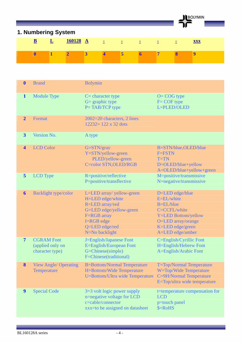
1. Numbering System B L 160128 A - - - - - xxx
0 1 2 3 4 5 6 7 8 9
0 Brand Bolymin
1 Module Type C= character type G= graphic type P= TAB/TCP type
O= COG type F= COF type L=PLED/OLED
2 Format 2002=20 characters, 2 lines 12232= 122 x 32 dots
3 Version No. A type
4 LCD Color G=STN/gray Y=STN/yellow-green PLED/yellow-green C=color STN,OLED/RGB
B=STN/blue,OLED/blue F=FSTN T=TN D=OLED/blue+yellow A=OLED/blue+yellow+green
5 LCD Type R=positive/reflective P=positive/transflective
M=positive/transmissive N=negative/transmissive
6 Backlight type/color L=LED array/ yellow-green H=LED edge/white R=LED array/red G=LED edge/yellow-green F=RGB array I=RGB edge Q=LED edge/red N=No backlight
D=LED edge/blue E=EL/white B=EL/blue C=CCFL/white Y=LED Bottom/yellow O=LED array/orange K=LED edge/green A=LED edge/amber
7 CGRAM Font (applied only on character type)
J=English/Japanese Font E=English/European Font G=Chinese(simple) F=Chinese(traditional)
C=English/Cyrillic Font H=English/Hebrew Font A=English/Arabic Font
8 View Angle/ Operating Temperature
B=Bottom/Normal Temperature H=Bottom/Wide Temperature U=Bottom/Ultra wide Temperature
T=Top/Normal Temperature W=Top/Wide Temperature C=9H/Normal Temperature E=Top/ultra wide temperature
9 Special Code 3=3 volt logic power supply n=negative voltage for LCD c=cable/connector xxx=to be assigned on datasheet
t=temperature compensation for LCD p=touch panel $=RoHS
BL160128A series - 5 -
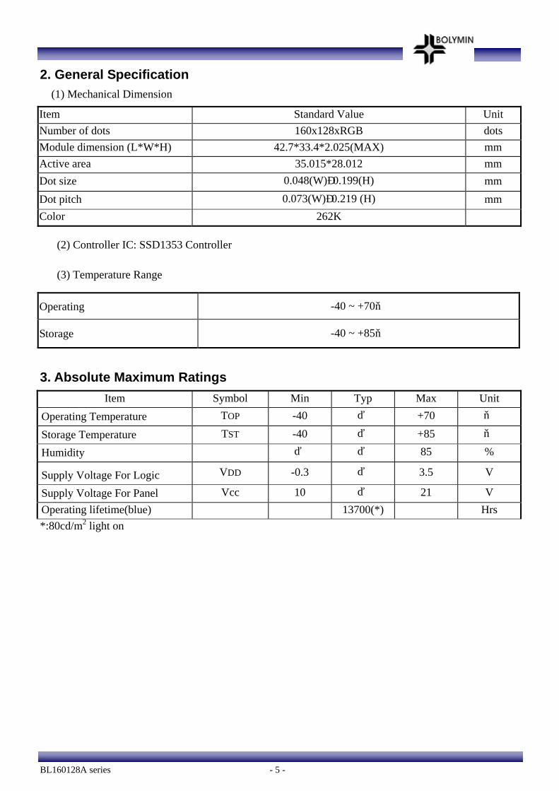
2. General Specification (1) Mechanical Dimension
Item Standard Value Unit Number of dots 160x128xRGB dots Module dimension (L*W*H) 42.7*33.4*2.025(MAX) mm Active area 35.015*28.012 mm Dot size 0.048(W)×0.199(H) mm Dot pitch 0.073(W)×0.219 (H) mm Color 262K
(2) Controller IC: SSD1353 Controller
(3) Temperature Range
Operating -40 ~ +70℃
Storage -40 ~ +85℃
3. Absolute Maximum Ratings
Item Symbol Min Typ Max Unit Operating Temperature TOP -40 - +70 ℃
Storage Temperature TST -40 - +85 ℃
Humidity - - 85 %
Supply Voltage For Logic VDD -0.3 - 3.5 V
Supply Voltage For Panel Vcc 10 - 21 V Operating lifetime(blue) 13700(*) Hrs *:80cd/m2 light on
BL160128A series - 6 -
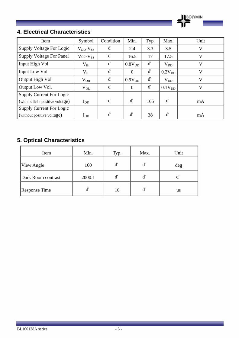
4. Electrical Characteristics Item Symbol Condition Min. Typ. Max. Unit
Supply Voltage For Logic VDD-VSS - 2.4 3.3 3.5 V Supply Voltage For Panel Vcc-VSS - 16.5 17 17.5 V Input High Vol VIH - 0.8VDD - VDD V Input Low Vol VIL - 0 - 0.2VDD V Output High Vol VOH - 0.9VDD - VDD V Output Low Vol. VOL - 0 - 0.1VDD V Supply Current For Logic (with built-in positive voltage) IDD - - 165 - mA Supply Current For Logic (without positive voltage) IDD - - 38 - mA
5. Optical Characteristics
Item Min. Typ. Max. Unit
View Angle 160 - - deg
Dark Room contrast 2000:1 - - -
Response Time - 10 - us
BL160128A series - 7 -
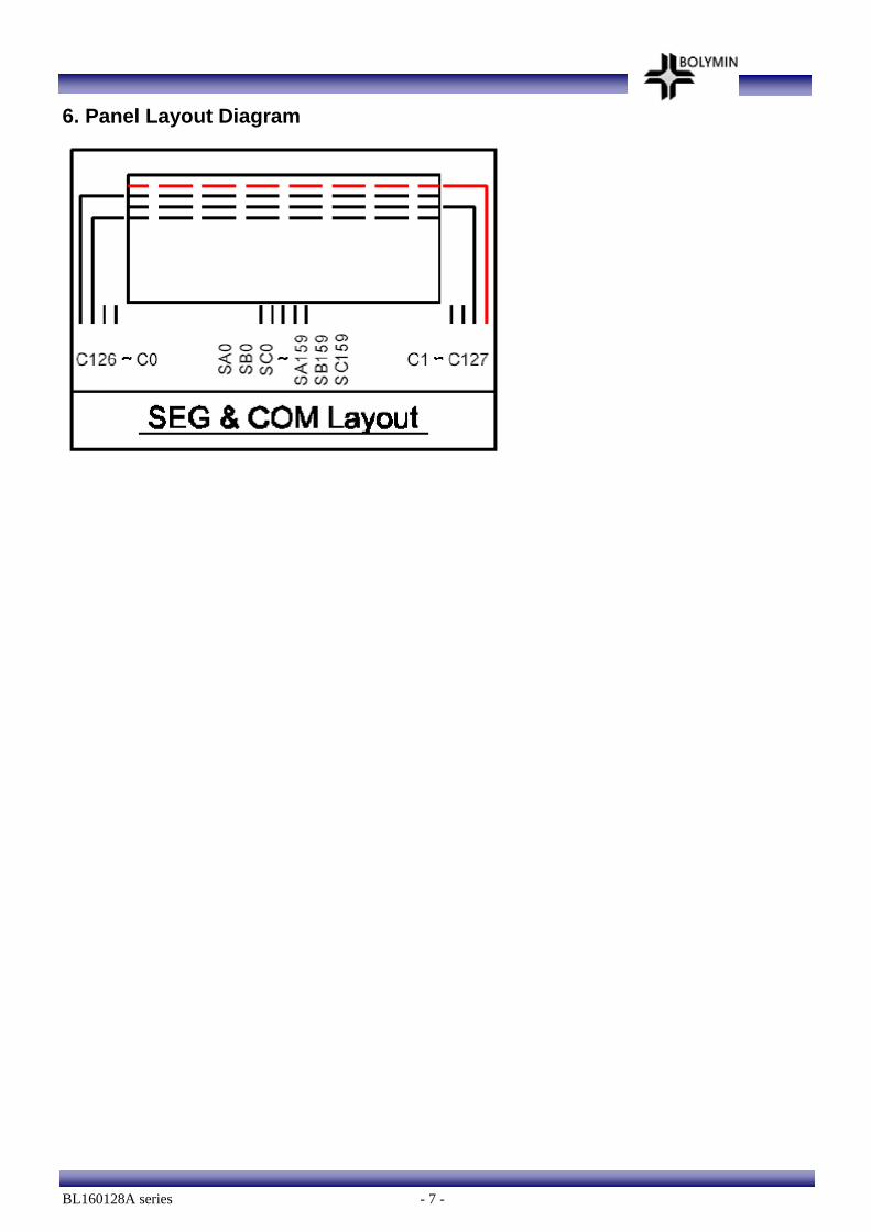
6. Panel Layout Diagram

BL160128A series - 8 -
7. Interface Pin Function
Pin No. Symbol Level Description
1 Vss 0V Ground
2 Vdd 3.3V Supply voltage for logic
3 CS H/L Chip select pin
4 /RES H/L Hardware Reset pin
5 D/C H/L H: Data; L: Command.
6 RW H/L 8080: data write enable pin 6800: Read/Write select pin
7 E H/L 8080: data read enable pin 6800: Read/Write enable pin
8 DB0 H/L Data bus line
9 DB1 H/L Data bus line
10 DB2 H/L Data bus line
11 DB3 H/L Data bus line
12 DB4 H/L Data bus line
13 DB5 H/L Data bus line
14 DB6 H/L Data bus line
15 DB7 H/L Data bus line
16 DISPOFF/
VCC -
H/L DISPOFF: Active L VCC: Analog power control (DC 17V)
Default:8080 series interface
BL160128A series - 9 -
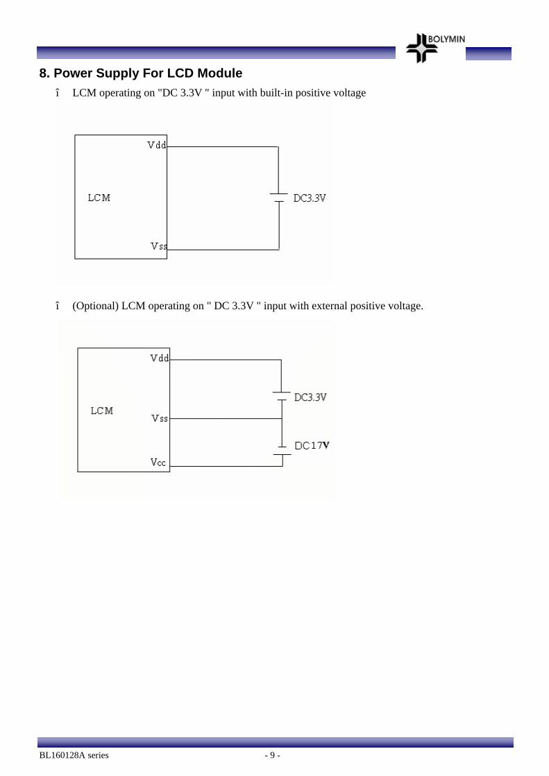
8. Power Supply For LCD Module * LCM operating on "DC 3.3V " input with built-in positive voltage
* (Optional) LCM operating on " DC 3.3V " input with external positive voltage.
BL160128A series - 10 -
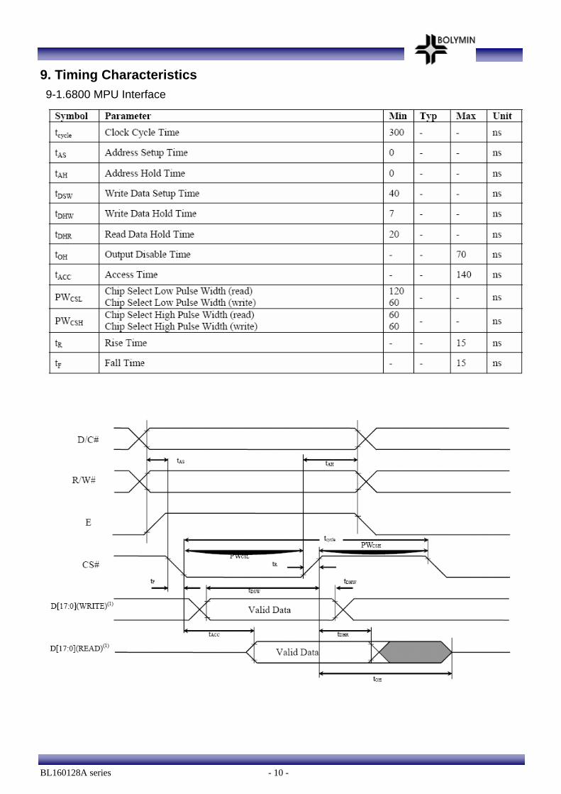
9. Timing Characteristics 9-1.6800 MPU Interface
BL160128A series - 11 -
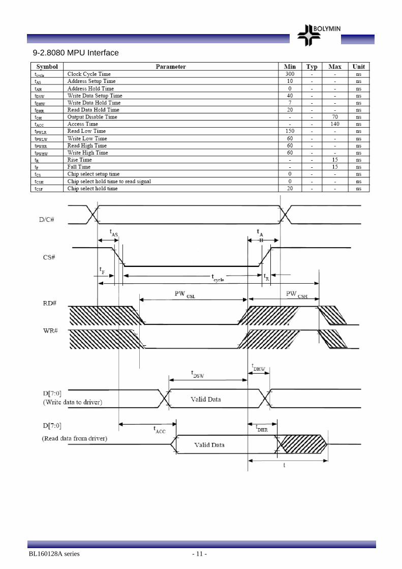
9-2.8080 MPU Interface
BL160128A series - 12 -
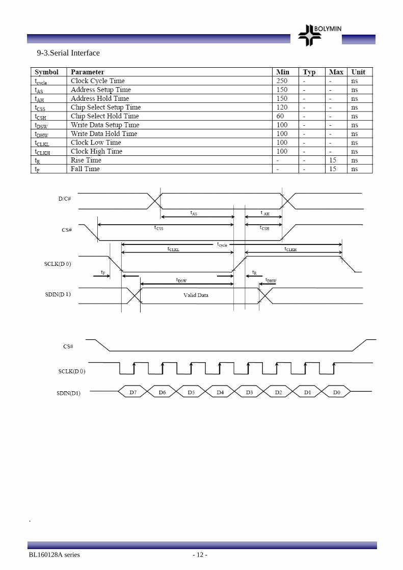
9-3.Serial Interface
.
BL160128A series - 13 -
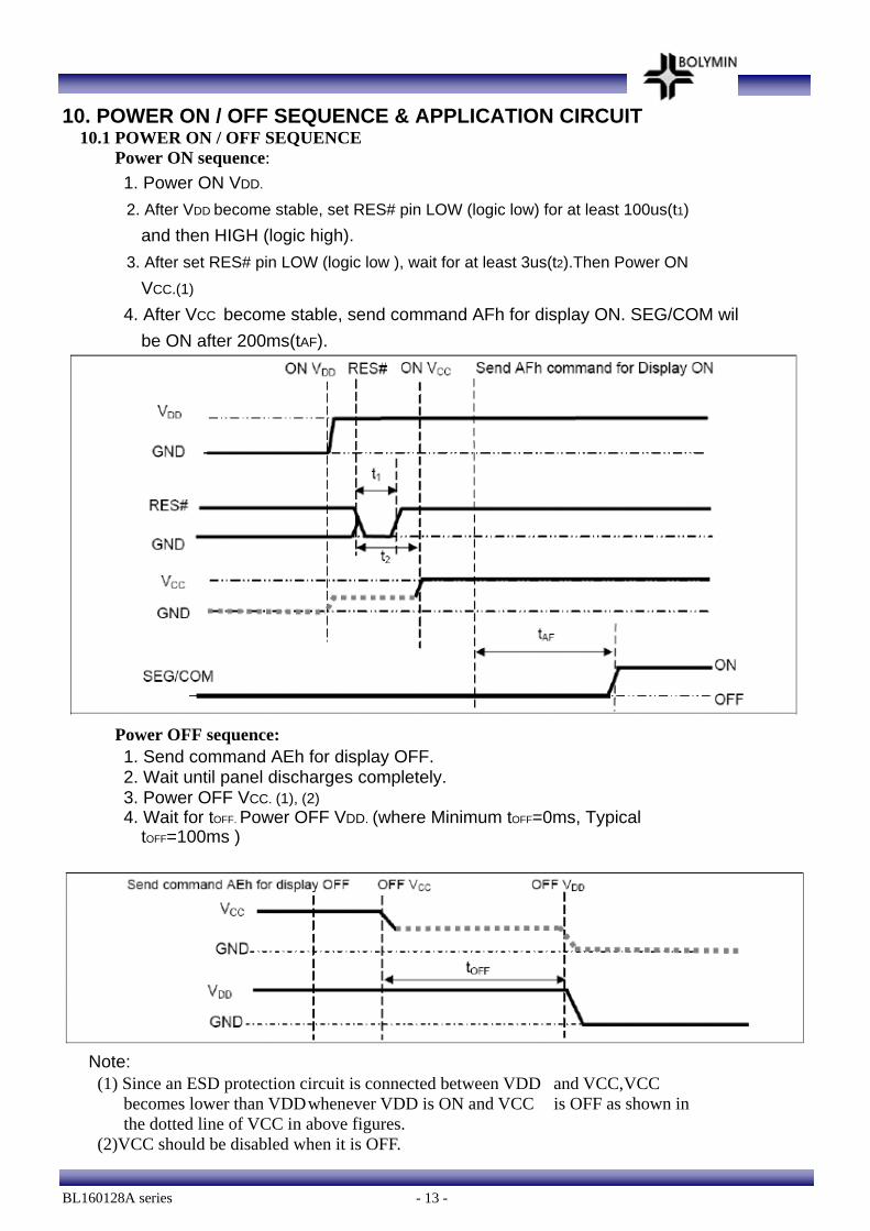
10. POWER ON / OFF SEQUENCE & APPLICATION CIRCUIT 10.1 POWER ON / OFF SEQUENCE
Power ON sequence: 1. Power ON VDD.
2. After VDD become stable, set RES# pin LOW (logic low) for at least 100us(t1) and then HIGH (logic high).
3. After set RES# pin LOW (logic low ), wait for at least 3us(t2).Then Power ON VCC.(1)
4. After VCC become stable, send command AFh for display ON. SEG/COM wil be ON after 200ms(tAF).
Power OFF sequence: 1. Send command AEh for display OFF. 2. Wait until panel discharges completely. 3. Power OFF VCC. (1), (2) 4. Wait for tOFF. Power OFF VDD. (where Minimum tOFF=0ms, Typical
tOFF=100ms )
Note: (1) Since an ESD protection circuit is connected between VDD and VCC, VCC
becomes lower than VDD whenever VDD is ON and VCC is OFF as shown in the dotted line of VCC in above figures.
(2)VCC should be disabled when it is OFF.
BL160128A series - 14 -
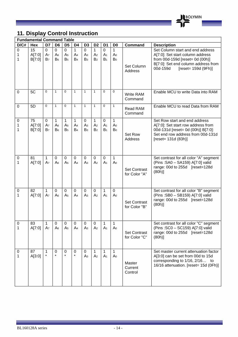
11. Display Control Instruction Fundamental Command Table D/C# Hex D7 D6 D5 D4 D3 D2 D1 D0 Command Description 0 1 1
15 A[7:0] B[7:0]
0 A7
B7
0 A6 B6
0 A5 B5
1 A4 B4
0 A3 B3
1 A2 B2
0 A1
B1
1 A0
B0 Set Column Address
Set Column start and end address A[7:0]: Set start column address from 00d-159d [reset= 0d (00h)] B[7:0]: Set end column address from 00d-159d [reset= 159d (9Fh)]
0 5C 0 1 0 1 1 1 0 0 Write RAM Command
Enable MCU to write Data into RAM
0 5D 0 1 0 1 1 1 0 1 Read RAM Command
Enable MCU to read Data from RAM
0 1 1
75 A[7:0] B[7:0]
0 A7
B7
1 A6 B6
1 A5 B5
1 A4 B4
0 A3 B3
1 A2 B2
0 A1
B1
1 A0
B0 Set Row Address
Set Row start and end address A[7:0]: Set start row address from 00d-131d [reset= 0d (00h)] B[7:0]: Set end row address from 00d-131d [reset= 131d (83h)]
0 1
81 A[7:0]
1 A7
0 A6
0 A5
0 A4
0 A3
0 A2
0 A1
1 A0
Set Contrast for Color "A"
Set contrast for all color "A" segment (Pins :SA0 – SA159) A[7:0] valid range: 00d to 255d [reset=128d (80h)]
0 1
82 A[7:0]
1 A7
0 A6
0 A5
0 A4
0 A3
0 A2
1 A1
0 A0
Set Contrast for Color "B"
Set contrast for all color "B" segment (Pins :SB0 – SB159) A[7:0] valid range: 00d to 255d [reset=128d (80h)]
0 1
83 A[7:0]
1 A7
0 A6
0 A5
0 A4
0 A3
0 A2
1 A1
1 A0
Set Contrast for Color "C"
Set contrast for all color "C" segment (Pins :SC0 – SC159) A[7:0] valid range: 00d to 255d [reset=128d (80h)]
0 1
87 A[3:0]
1 *
0 *
0 *
0 *
0 A3
1 A2
1 A1
1 A0
Master Current Control
Set master current attenuation factor A[3:0] can be set from 00d to 15d corresponding to 1/16, 2/16… to 16/16 attenuation. [reset= 15d (0Fh)]
BL160128A series - 15 -
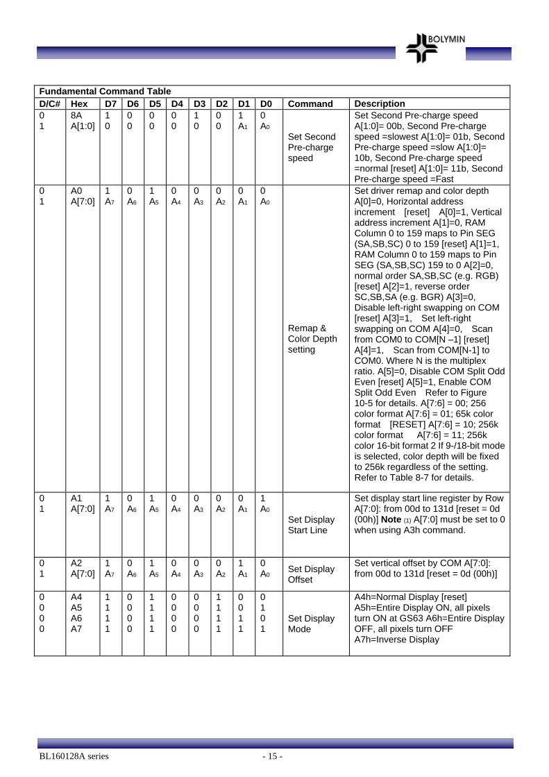
Fundamental Command Table D/C# Hex D7 D6 D5 D4 D3 D2 D1 D0 Command Description 0 1
8A A[1:0]
1 0
0 0
0 0
0 0
1 0
0 0
1 A1
0 A0
Set Second Pre-charge speed
Set Second Pre-charge speed A[1:0]= 00b, Second Pre-charge speed =slowest A[1:0]= 01b, Second Pre-charge speed =slow A[1:0]= 10b, Second Pre-charge speed =normal [reset] A[1:0]= 11b, Second Pre-charge speed =Fast
0 1
A0 A[7:0]
1 A7
0 A6
1 A5
0 A4
0 A3
0 A2
0 A1
0 A0
Remap & Color Depth setting
Set driver remap and color depth A[0]=0, Horizontal address increment [reset] A[0]=1, Vertical address increment A[1]=0, RAM Column 0 to 159 maps to Pin SEG (SA,SB,SC) 0 to 159 [reset] A[1]=1, RAM Column 0 to 159 maps to Pin SEG (SA,SB,SC) 159 to 0 A[2]=0, normal order SA,SB,SC (e.g. RGB) [reset] A[2]=1, reverse order SC,SB,SA (e.g. BGR) A[3]=0, Disable left-right swapping on COM [reset] A[3]=1, Set left-right swapping on COM A[4]=0, Scan from COM0 to COM[N –1] [reset] A[4]=1, Scan from COM[N-1] to COM0. Where N is the multiplex ratio. A[5]=0, Disable COM Split Odd Even [reset] A[5]=1, Enable COM Split Odd Even Refer to Figure 10-5 for details. A[7:6] = 00; 256 color format A[7:6] = 01; 65k color format [RESET] A[7:6] = 10; 256k color format A[7:6] = 11; 256k color 16-bit format 2 If 9-/18-bit mode is selected, color depth will be fixed to 256k regardless of the setting. Refer to Table 8-7 for details.
0 1
A1 A[7:0]
1 A7
0 A6
1 A5
0 A4
0 A3
0 A2
0 A1
1 A0
Set Display Start Line
Set display start line register by Row A[7:0]: from 00d to 131d [reset = 0d (00h)] Note (1) A[7:0] must be set to 0 when using A3h command.
0 1
A2 A[7:0]
1 A7
0 A6
1 A5
0 A4
0 A3
0 A2
1 A1
0 A0 Set Display
Offset
Set vertical offset by COM A[7:0]: from 00d to 131d [reset = 0d (00h)]
0 0 0 0
A4 A5 A6 A7
1 1 1 1
0 0 0 0
1 1 1 1
0 0 0 0
0 0 0 0
1 1 1 1
0 0 1 1
0 1 0 1
Set Display Mode
A4h=Normal Display [reset] A5h=Entire Display ON, all pixels turn ON at GS63 A6h=Entire Display OFF, all pixels turn OFF A7h=Inverse Display
BL160128A series - 16 -
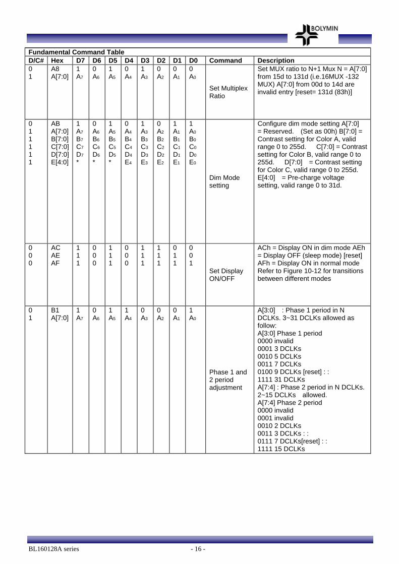
Fundamental Command Table D/C# Hex D7 D6 D5 D4 D3 D2 D1 D0 Command Description 0 1
A8 A[7:0]
1 A7
0 A6
1 A5
0 A4
1 A3
0 A2
0 A1
0 A0
Set Multiplex Ratio
Set MUX ratio to N+1 Mux N = A[7:0] from 15d to 131d (i.e.16MUX -132 MUX) A[7:0] from 00d to 14d are invalid entry [reset= 131d (83h)]
0 1 1 1 1 1
AB A[7:0] B[7:0] C[7:0] D[7:0] E[4:0]
1 A7
B7
C7
D7
*
0 A6 B6 C6 D6
*
1 A5 B5 C5 D5
*
0 A4 B4 C4 D4
E4
1 A3 B3 C3 D3 E3
0 A2 B2 C2 D2 E2
1 A1 B1 C1 D1 E1
1 A0
B0
C0
D0
E0
Dim Mode setting
Configure dim mode setting A[7:0] = Reserved. (Set as 00h) B[7:0] = Contrast setting for Color A, valid range 0 to 255d. C[7:0] = Contrast setting for Color B, valid range 0 to 255d. D[7:0] = Contrast setting for Color C, valid range 0 to 255d. E[4:0] = Pre-charge voltage setting, valid range 0 to 31d.
0 0 0
AC AE AF
1 1 1
0 0 0
1 1 1
0 0 0
1 1 1
1 1 1
0 1 1
0 0 1
Set Display ON/OFF
ACh = Display ON in dim mode AEh = Display OFF (sleep mode) [reset] AFh = Display ON in normal mode Refer to Figure 10-12 for transitions between different modes
0 1
B1 A[7:0]
1 A7
0 A6
1 A5
1 A4
0 A3
0 A2
0 A1
1 A0
Phase 1 and 2 period adjustment
A[3:0] : Phase 1 period in N DCLKs. 3~31 DCLKs allowed as follow: A[3:0] Phase 1 period 0000 invalid 0001 3 DCLKs 0010 5 DCLKs 0011 7 DCLKs 0100 9 DCLKs [reset] : : 1111 31 DCLKs A[7:4] : Phase 2 period in N DCLKs. 2~15 DCLKs allowed. A[7:4] Phase 2 period 0000 invalid 0001 invalid 0010 2 DCLKs 0011 3 DCLKs : : 0111 7 DCLKs[reset] : : 1111 15 DCLKs
BL160128A series - 17 -
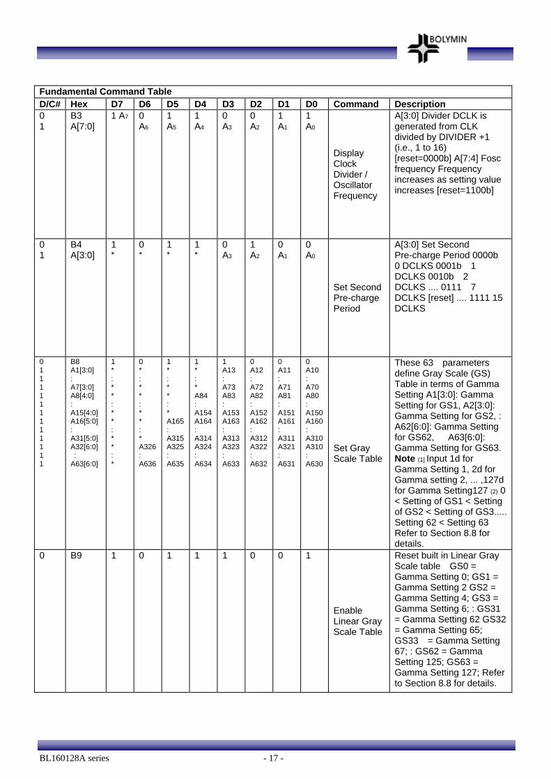
Fundamental Command Table D/C# Hex D7 D6 D5 D4 D3 D2 D1 D0 Command Description 0 1
B3 A[7:0]
1 A7 0 A6
1 A5
1 A4
0 A3
0 A2
1 A1
1 A0
Display Clock Divider / Oscillator Frequency
A[3:0] Divider DCLK is generated from CLK divided by DIVIDER +1 (i.e., 1 to 16) [reset=0000b] A[7:4] Fosc frequency Frequency increases as setting value increases [reset=1100b]
0 1
B4 A[3:0]
1 *
0 *
1 *
1 *
0 A3
1 A2
0 A1
0 A0
Set Second Pre-charge Period
A[3:0] Set Second Pre-charge Period 0000b 0 DCLKS 0001b 1 DCLKS 0010b 2 DCLKS .... 0111 7 DCLKS [reset] .... 1111 15 DCLKS
0 1 1 1 1 1 1 1 1 1 1 1 1
B8 A1[3:0] : A7[3:0] A8[4:0] : A15[4:0] A16[5:0] : A31[5:0] A32[6:0] : A63[6:0]
1 * : * * : * * : * * : *
0 * : * * : * * : * A326 : A636
1 * : * * : * A165 : A315 A325 : A635
1 * : * A84 : A154 A164 : A314 A324 : A634
1 A13 : A73 A83 : A153 A163: A313 A323: A633
0 A12 : A72 A82 : A152 A162: A312 A322: A632
0 A11 : A71 A81 : A151 A161: A311 A321: A631
0 A10 : A70 A80 : A150 A160 : A310 A310 : A630
Set Gray Scale Table
These 63 parameters define Gray Scale (GS) Table in terms of Gamma Setting A1[3:0]: Gamma Setting for GS1, A2[3:0]: Gamma Setting for GS2, : A62[6:0]: Gamma Setting for GS62, A63[6:0]: Gamma Setting for GS63. Note (1] Input 1d for Gamma Setting 1, 2d for Gamma setting 2, ... ,127d for Gamma Setting127 (2) 0 < Setting of GS1 < Setting of GS2 < Setting of GS3..... Setting 62 < Setting 63 Refer to Section 8.8 for details.
0 B9 1 0 1 1 1 0 0 1
Enable Linear Gray Scale Table
Reset built in Linear Gray Scale table GS0 = Gamma Setting 0; GS1 = Gamma Setting 2 GS2 = Gamma Setting 4; GS3 = Gamma Setting 6; : GS31 = Gamma Setting 62 GS32 = Gamma Setting 65; GS33 = Gamma Setting 67; : GS62 = Gamma Setting 125; GS63 = Gamma Setting 127; Refer to Section 8.8 for details.
BL160128A series - 18 -
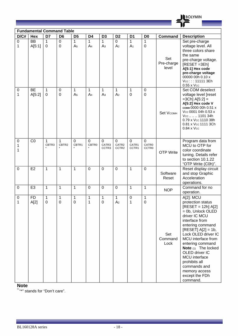
Fundamental Command Table D/C# Hex D7 D6 D5 D4 D3 D2 D1 D0 Command Description 0 1
BB A[5:1]
1 0
0 0
1 A5
1 A4
1 A3
0 A2
1 A1
1 0
Set Pre-charge
level
Set pre-charge voltage level. All three colors share the same pre-charge voltage. [RESET =3Eh] A[5:1] Hex code pre-charge voltage 00000 00h 0.10 x VCC : : : 11111 3Eh 0.55 x VCC
0 1
BE A[5:2]
1 0
0 0
1 A5
1 A4
1 A3
1 A2
1 0
0 0
Set VCOMH
Set COM deselect voltage level [reset =3Ch] A[5:2] = A[5:2] Hex code V
COMH 0000 00h 0.51 x VCC 0001 04h 0.53 x VCC .. .. .. 1101 34h 0.79 x VCC 1110 38h 0.81 x VCC 1111 3Ch 0.84 x VCC
0 1 1
C0 1 CBTR3 *
1 CBTR2 *
0 CBTR1 *
0 CBTR0 *
0 CATR3CCTR3
0 CATR2 CCTR2
0 CATR1 CCTR1
0 CATR0 CCTR0
OTP Write
Program data from MCU to OTP for color coordinate tuning. Details refer to section 10.1.22 “OTP Write (C0h)”.
0 E2 1 1 1 0 0 0 1 0 Software
Reset
Reset display circuit and stop Graphic Acceleration operations.
0 E3 1 1 1 0 0 0 1 1 NOP Command for no operation.
0 1
FD A[2]
1 0
1 0
1 0
1 1
1 0
1 A2
0 1
1 0
Set Command
Lock
A[2]: MCU protection status [RESET = 12h] A[2] = 0b, Unlock OLED driver IC MCU interface from entering command [RESET] A[2] = 1b, Lock OLED driver IC MCU interface from entering command Note (1) The locked OLED driver IC MCU interface prohibits all commands and memory access except the FDh command.
Note (1)
“*” stands for “Don’t care”.
BL160128A series - 19 -
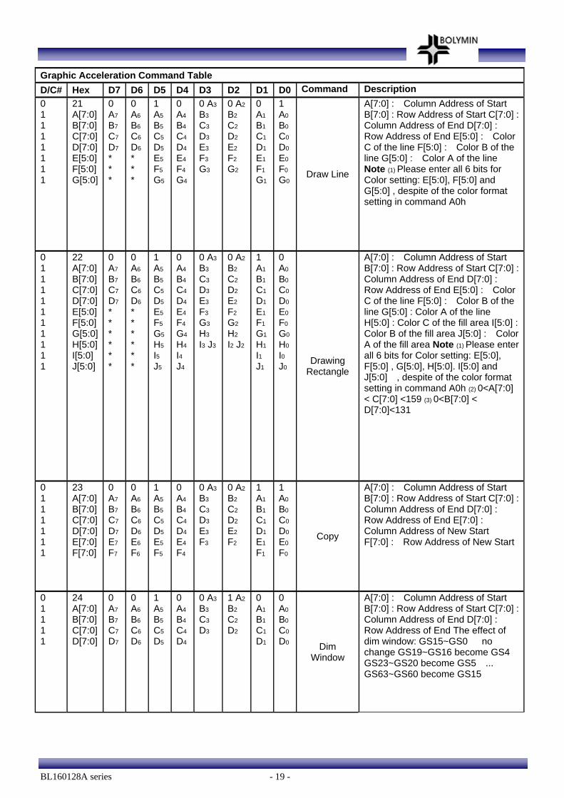
Graphic Acceleration Command Table D/C# Hex D7 D6 D5 D4 D3 D2 D1 D0 Command Description 0 1 1 1 1 1 1 1
21 A[7:0] B[7:0] C[7:0] D[7:0] E[5:0] F[5:0] G[5:0]
0 A7
B7
C7
D7
* * *
0 A6 B6 C6 D6
* * *
1 A5 B5 C5 D5
E5
F5
G5
0 A4 B4 C4 D4 E4 F4 G4
0 A3 B3 C3 D3 E3 F3 G3
0 A2 B2 C2 D2 E2 F2 G2
0 A1
B1
C1
D1
E1
F1 G1
1 A0
B0
C0
D0
E0
F0
G0Draw Line
A[7:0] : Column Address of Start B[7:0] : Row Address of Start C[7:0] : Column Address of End D[7:0] : Row Address of End E[5:0] : Color C of the line F[5:0] : Color B of the line G[5:0] : Color A of the line Note (1) Please enter all 6 bits for Color setting: E[5:0], F[5:0] and G[5:0] , despite of the color format setting in command A0h
0 1 1 1 1 1 1 1 1 1 1
22 A[7:0] B[7:0] C[7:0] D[7:0] E[5:0] F[5:0] G[5:0] H[5:0] I[5:0] J[5:0]
0 A7
B7
C7
D7
* * * * * *
0 A6 B6 C6 D6
* * * * * *
1 A5 B5 C5 D5
E5
F5
G5
H5
I5
J5
0 A4 B4 C4 D4 E4 F4 G4 H4 I4 J4
0 A3 B3 C3 D3 E3 F3 G3 H3 I3 J3
0 A2 B2 C2 D2 E2 F2 G2 H2 I2 J2
1 A1
B1
C1
D1
E1
F1 G1
H1
I1 J1
0 A0
B0
C0
D0
E0
F0
G0
H0
I0
J0 Drawing
Rectangle
A[7:0] : Column Address of Start B[7:0] : Row Address of Start C[7:0] : Column Address of End D[7:0] : Row Address of End E[5:0] : Color C of the line F[5:0] : Color B of the line G[5:0] : Color A of the line H[5:0] : Color C of the fill area I[5:0] : Color B of the fill area J[5:0] : Color A of the fill area Note (1) Please enter all 6 bits for Color setting: E[5:0], F[5:0] , G[5:0], H[5:0]. I[5:0] and J[5:0] , despite of the color format setting in command A0h (2) 0<A[7:0] < C[7:0] <159 (3) 0<B[7:0] < D[7:0]<131
0 1 1 1 1 1 1
23 A[7:0] B[7:0] C[7:0] D[7:0] E[7:0] F[7:0]
0 A7
B7
C7
D7
E7
F7
0 A6 B6 C6 D6 E6 F6
1 A5 B5 C5 D5 E5
F5
0 A4 B4 C4 D4 E4 F4
0 A3 B3 C3 D3 E3 F3
0 A2 B2 C2 D2 E2 F2
1 A1
B1
C1
D1
E1
F1
1 A0
B0
C0
D0
E0
F0
Copy
A[7:0] : Column Address of Start B[7:0] : Row Address of Start C[7:0] : Column Address of End D[7:0] : Row Address of End E[7:0] : Column Address of New Start F[7:0] : Row Address of New Start
0 1 1 1 1
24 A[7:0] B[7:0] C[7:0] D[7:0]
0 A7
B7
C7
D7
0 A6 B6 C6 D6
1 A5 B5 C5 D5
0 A4 B4 C4 D4
0 A3 B3 C3 D3
1 A2 B2 C2 D2
0 A1
B1
C1
D1
0 A0
B0
C0
D0 Dim Window
A[7:0] : Column Address of Start B[7:0] : Row Address of Start C[7:0] : Column Address of End D[7:0] : Row Address of End The effect of dim window: GS15~GS0 no change GS19~GS16 become GS4 GS23~GS20 become GS5 ... GS63~GS60 become GS15
BL160128A series - 20 -
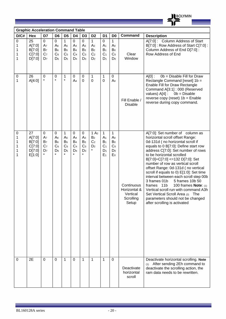
Graphic Acceleration Command Table D/C# Hex D7 D6 D5 D4 D3 D2 D1 D0 Command Description 0 1 1 1 1
25 A[7:0] B[7:0] C[7:0] D[7:0]
0 A7
B7
C7
D7
0 A6 B6 C6 D6
1 A5 B5 C5 D5
0 A4 B4 C4 D4
0 A3 B3 C3 D3
1 A2 B2 C2 D2
0 A1
B1
C1
D1
1 A0
B0
C0
D0
Clear Window
A[7:0] : Column Address of Start B[7:0] : Row Address of Start C[7:0] : Column Address of End D[7:0] : Row Address of End
0 1
26 A[4:0]
0 *
0 *
1 *
0 A4
0 0
1 0
1 0
0 A0
Fill Enable / Disable
A[0] : 0b = Disable Fill for Draw Rectangle Command [reset] 1b = Enable Fill for Draw Rectangle Command A[3:1] : 000 (Reserved values) A[4] : 0b = Disable reverse copy (reset) 1b = Enable reverse during copy command.
0 1 1 1 1 1
27 A[7:0] B[7:0] C[7:0] D[7:0] E[1:0]
0 A7
B7
C7
D7
*
0 A6 B6 C6 D6
*
1 A5 B5 C5 D5
*
0 A4 B4 C4 D4
*
0 A3 B3 C3 D3
*
1 A2 B2 C2 D2
*
1 A1
B1
C1
D1
E1
1 A0
B0
C0
D0
E0
Continuous Horizontal &
Vertical Scrolling
Setup
A[7:0]: Set number of column as horizontal scroll offset Range: 0d-131d ( no horizontal scroll if equals to 0 B[7:0]: Define start row address C[7:0]: Set number of rows to be horizontal scrolled B[7:0]+C[7:0] <=132 D[7:0]: Set number of row as vertical scroll offset Range: 0d-131d ( no vertical scroll if equals to 0) E[1:0]: Set time interval between each scroll step 00b 3 frames 01b 5 frames 10b 50 frames 11b 100 frames Note: (1) Vertical scroll run with command A3h Set Vertical Scroll Area (2) The parameters should not be changed after scrolling is activated
0 2E 0 0 1 0 1 1 1 0
Deactivate horizontal
scroll
Deactivate horizontal scrolling. Note (1) After sending 2Eh command to deactivate the scrolling action, the ram data needs to be rewritten.
BL160128A series - 21 -
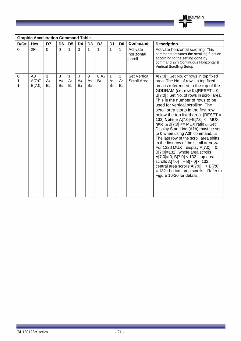
Graphic Acceleration Command Table D/C# Hex D7 D6 D5 D4 D3 D2 D1 D0 Command Description 0 2F 0 0 1 0 1 1 1 1 Activate
horizontal scroll
Activate horizontal scrolling. This command activates the scrolling function according to the setting done by command 27h Continuous Horizontal & Vertical Scrolling Setup
0 1 1
A3 A[7:0] B[7:0]
1 A7
B7
0 A6 B6
1 A5
B5
0 A4
B4
0 A3 B3
0 A2 B2
1 A1
B1
1 A0
B0
Set Vertical Scroll Area
A[7:0] : Set No. of rows in top fixed area. The No. of rows in top fixed area is referenced to the top of the GDDRAM (i.e. row 0).[RESET = 0] B[7:0] : Set No. of rows in scroll area. This is the number of rows to be used for vertical scrolling. The scroll area starts in the first row below the top fixed area. [RESET = 132] Note (1) A[7:0]+B[7:0] <= MUX ratio (2) B[7:0] <= MUX ratio (3) Set Display Start Line (A1h) must be set to 0 when using A3h command. (4) The last row of the scroll area shifts to the first row of the scroll area. (5) For 132d MUX display A[7:0] = 0, B[7:0]=132 : whole area scrolls A[7:0]= 0, B[7:0] < 132 : top area scrolls A[7:0] + B[7:0] < 132 : central area scrolls A[7:0] + B[7:0] = 132 : bottom area scrolls Refer to Figure 10-20 for details.
BL160128A series - 22 -
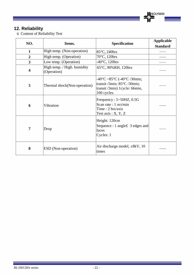
12. Reliability ■Content of Reliability Test
NO. Items. Specification Applicable Standard
1 High temp. (Non-operation) 85°C, 240hrs —— 2 High temp. (Operation) 70°C, 120hrs —— 3 Low temp. (Operation) -40°C, 120hrs ——
4 High temp. / High. humidity (Operation)
65°C, 90%RH, 120hrs ——
5 Thermal shock(Non-operation) -40°C ~85°C (-40°C /30min; transit /3min; 85°C /30min; transit /3min) 1cycle: 66min, 100 cycles.
——
6 Vibration Frequency : 5~50HZ, 0.5G Scan rate : 1 oct/min Time : 2 hrs/axis Test axis : X, Y, Z
——
7 Drop
Height: 120cm Sequence : 1 angle、3 edges and faces Cycles: 1
——
8 ESD (Non-operation) Air discharge model, ±8kV, 10 times
——
BL160128A series - 23 -
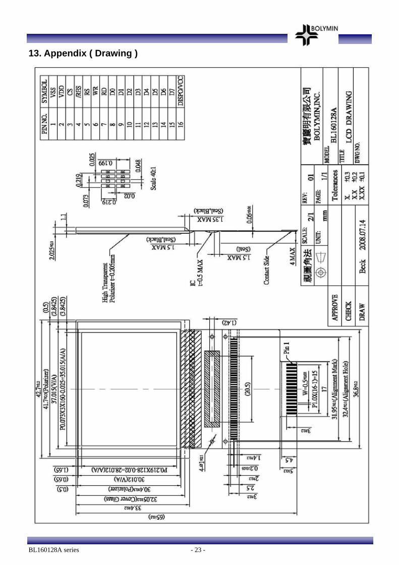
13. Appendix ( Drawing )