Embed Size (px)
Citation preview
SPECIFICATIONS
FOR THE
UTILITIES UPGRADE AND QUAD RENOVATION
AT
PLEASANT VALLEY SCHOOL OF ENGINEERING AND ARTS
700 TEMPLE AVENUE CAMARILLO, CA 93010
FOR:
PLEASANT VALLEY SCHOOL DISTRICT
600 TEMPLE AVENUECAMARILLO, CA 93010
MARCH 6, 2021
PREPARED BY:JORDAN, GILBERT & BAIN
LANDSCAPE ARCHITECTS, INC. 459 NORTH VENTURA AVENUE
VENTURA, CA 93001
04-223/06/21
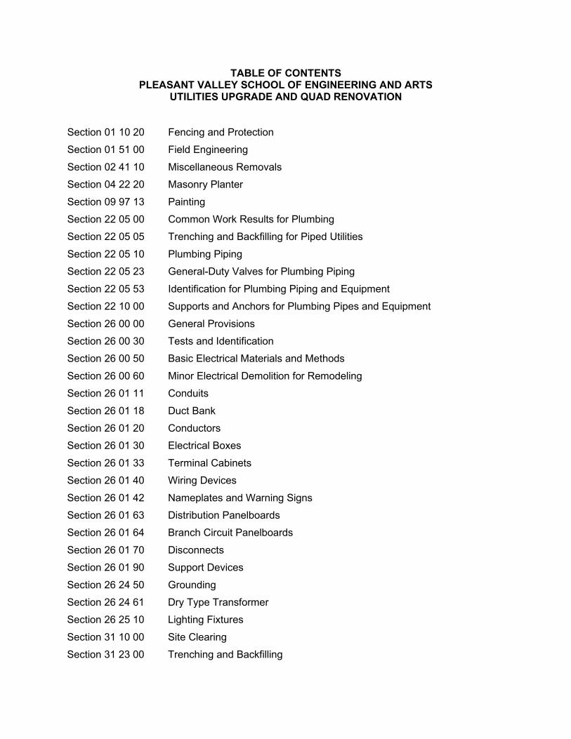
TABLE OF CONTENTS PLEASANT VALLEY SCHOOL OF ENGINEERING AND ARTS
UTILITIES UPGRADE AND QUAD RENOVATION
Section 01 10 20 Fencing and Protection Section 01 51 00 Field Engineering Section 02 41 10 Miscellaneous Removals Section 04 22 20 Masonry Planter Section 09 97 13 Painting Section 22 05 00 Common Work Results for Plumbing Section 22 05 05 Trenching and Backfilling for Piped Utilities Section 22 05 10 Plumbing Piping Section 22 05 23 General-Duty Valves for Plumbing Piping Section 22 05 53 Identification for Plumbing Piping and Equipment Section 22 10 00 Supports and Anchors for Plumbing Pipes and Equipment Section 26 00 00 General Provisions Section 26 00 30 Tests and Identification Section 26 00 50 Basic Electrical Materials and Methods Section 26 00 60 Minor Electrical Demolition for Remodeling Section 26 01 11 Conduits Section 26 01 18 Duct Bank Section 26 01 20 Conductors Section 26 01 30 Electrical Boxes Section 26 01 33 Terminal Cabinets Section 26 01 40 Wiring Devices Section 26 01 42 Nameplates and Warning Signs Section 26 01 63 Distribution Panelboards Section 26 01 64 Branch Circuit Panelboards Section 26 01 70 Disconnects Section 26 01 90 Support Devices Section 26 24 50 Grounding Section 26 24 61 Dry Type Transformer Section 26 25 10 Lighting Fixtures Section 31 10 00 Site Clearing Section 31 23 00 Trenching and Backfilling

Section 31 23 13 Excavation and Fill Section 31 25 00 Construction Stormwater Pollution Prevention Section 32 12 16 Asphalt Concrete Paving Section 32 13 13 Site Concrete Section 32 13 14 Site Concrete Reinforcement Section 32 13 20 Landscape Concrete Work Section 32 14 13 Concrete Pavers Section 32 84 23 Irrigation System Section 32 93 43 Tree Planting Section 32 94 60 Landscape Maintenance Section 33 41 00 Storm Drainage Piping Section 33 49 00 Storm Drainage Structures

PVSEA UTILITIES UPGRADE AND QUAD RENOVATION FENCING AND PROTECTION SECTION 01 10 20 - 1
SECTION 01 10 20 FENCING AND PROTECTION
PART 1 GENERAL 1.01 SECTION INCLUDES
This section includes general requirements for temporary fencing and protection of the work area.
1.02 SUBMITTALS
Submit, for approval, all catalog cuts and or specification sheets for all fencing products. 1.03 QUALITY ASSURANCE
Fencing shall be installed by a qualified fence company with experience in the installation of temporary fencing.
PART 2 PRODUCTS 2.01 TEMPORARY FENCING
Temporary fencing shall be 6 feet high chain link fence fabric attached to post and frames in a secure manner. Barb wire and or razor wire is not allowed.
PART 3 EXECUTION 3.01 FENCE LAYOUT
Contractor shall submit, to the District for approval, a schematic fence layout showing the location of fence panels and method of attachment of panels and post. This plan must be approved by the District prior to start of the work.
3.02 FENCE INSTALLATION
A. Install fencing and post so that no damage occurs to the existing underground conduits or paving. Immediately repair all damage to the existing conditions that may occur as a result of the fence installation.
B. If fence panels have post with a horizontal support frame, make sure they are
visually apparent to prevent any trip hazard.

PVSEA UTILITIES UPGRADE AND QUAD RENOVATION FENCING AND PROTECTION SECTION 01 10 20 - 2
3.03 FENCE REPAIR Immediately repair any damage to the fencing that may occur.
END OF SECTION 01 10 20
PVSEA UTILITIES UPGRADE AND QUAD RENOVATION FIELD ENGINEERING SECTION 01 51 00 - 1
SECTION 01 51 00 FIELD ENGINEERING
PART 1 GENERAL 1.01 DESCRIPTION
Provide materials, equipment, and transportation and perform labor as required for construction surveying.
1.02 RELATED DOCUMENTS
Drawings and general provisions of the Contract, including General and Supplementary Conditions and other Division 1 Specifications, apply to this Section.
1.03 RELATED WORK SPECIFIED ELSEWHERE
Section 33 41 00 – Storm Drainage Section 32 12 16 – Asphalt Concrete Paving Section 32 13 13 – Site Concrete
1.04 STANDARD SPECIFICATIONS
A. Construction materials and methods shall be in accordance with the Standard
Specifications for Public Works Construction, 2018 edition (SSPWC), published by Building News, Inc., except as modified or otherwise specified herein (hereinafter the Standard Specifications).
B. In case of conflict between the Standard Specifications and the project
specifications, the project specifications shall govern.
1.05 REGULATORY REQUIREMENTS
A. Construction shall comply with the California Code of Regulations, Title 24, Part 2 (the California Building Code), most recent effective edition.
B. Construction shall comply with applicable health and safety laws and standards
including rules, orders and regulations of the State of California Construction and General Industry Safety Orders, the Occupational Safety and Health Act of 1970, and the Construction Safety Act.
1.06 SUBMITTALS
A. Provide submittals according to the Conditions of the Contract and Division 1 “Submittal Procedures” section.
B. Refer to “Submittal Requirements and Schedule” at the end of this Section.

PVSEA UTILITIES UPGRADE AND QUAD RENOVATION FIELD ENGINEERING SECTION 01 51 00 - 2
1.07 RECORD DOCUMENTS
Comply with requirements of Division 1, “Project Record Documents” section. 1.08 QUALITY ASSURANCE
Retain a Land Surveyor, registered in the State of California, and acceptable to Architect / Engineer and Owner.
PART 2 PRODUCTS
(Not Used) PART 3 EXECUTION 3.01 SURVEY CONTROL
A. Confirm location, condition, datum, horizontal and vertical control data for survey control points given on the Drawings, with the Topographic Mapping Surveyor. 1. Protect survey control points during construction.
B. Establish additional survey control points throughout the work site in locations
that will not be disturbed by construction activities. 1. Locate control points such that there are at least two readily useable for
each individual work area requiring surveying. 2. Record locations of control points on Record Documents, including
description and horizontal and vertical survey data.
C. Survey horizontal and vertical locations of existing buried conduits, pipelines, and structures to be joined by, or which may conflict with, new construction and which have been exposed by potholing pursuant to requirements of individual technical specification sections; while exposed, observe and record conduit / pipe size and material. Redline this information to scale on a hardcopy of the applicable plan (or plan and profile) and provide to the Engineer for review and resolution of conflicts, if any. Allow a minimum of five (5) working days for review; more time may be required depending on the completeness of information provided and on the extent of the conflicts.
D. Layout and provide construction stakes for the work, including:
1. Line and grade control for rough grading operations, including area grading, cut and fill slopes, subgrade for building pads and pavements.
2. Line and grade control for finish grading including drainage swales. 3. Line and grade control and grade certification prior to backfill for gravity
pipelines and related structures. 4. Where called for on the Drawings, grade control and grade certification
prior to backfill for pressure pipelines.
PVSEA UTILITIES UPGRADE AND QUAD RENOVATION FIELD ENGINEERING SECTION 01 51 00 - 3
5. Line and grade control for concrete flatwork, walks, ramps, stairs, curbs, gutters, and walls.
6. Line and grade control for A.C. and concrete pavements.
E. Survey and certify finish surface of completed building pad prior to any work involving plumbing, utilities, or foundations.
F. Survey forms for concrete walks and ramps prior to ordering concrete to ensure
that accessibility requirements for slope and cross-slope will be conformed with. G. Where design longitudinal gradient is less than 1% (1/8 inch per foot) survey
gutter or curb and gutter forms prior to ordering concrete to ensure that design slope is being achieved.
H. For asphalt concrete and concrete pavement, prior to scheduling placement of
pavement confirm that surface of aggregate base course has been constructed to the design elevation and slope within tolerances specified in Section 02310, Subsection 3.03B.
I. Provide record surveying pursuant to requirements of individual technical specification sections.
END OF SECTION 01 51 00

PVSEA UTILITIES UPGRADE AND QUAD RENOVATION MISCELLANEOUS REMOVALS SECTION 02 41 10 - 1
SECTION 02 41 10 MISCELLANEOUS REMOVALS
PART 1 GENERAL 1.01 SECTION INCLUDES
This section includes general requirements for the removal of the existing concrete paving, asphalt paving, landscaping, and miscellaneous items.
1.02 IMPORT SOIL
The source of any required imported soil shall be tested and approved by the District prior to any delivery.
1.03 DISPOSAL OF MATERIALS
Remove items such as landscape materials, concrete paving, asphalt paving, and all other miscellaneous items scheduled to be removed and properly dispose of these items as they accumulate. Do not store or permit debris to accumulate on the site.
PART 2 PRODUCTS
(Not Used) PART 3 EXECUTION 3.01 INSPECTION
A. Prior to starting, inspect the site with the District Inspector to verify all removals required to complete the work.
B. Examine surfaces for conditions that will adversely affect execution, permanence,
and quality of work of this Section. C. Do not proceed with work until unsatisfactory conditions have been corrected. D. Locate existing active utility lines and provide for their protection.
3.02 CLARIFICATION
Drawings do not indicate all objects existing on site. Before commencing work, verify with the District any existing items that may affect the work.
PVSEA UTILITIES UPGRADE AND QUAD RENOVATION MISCELLANEOUS REMOVALS SECTION 02 41 10 - 2
3.03 PROTECTION OF UTILITIES
There are existing utilities within the work area. The approximate locations are indicated on the drawings. Protect all utilities. If directed by the District Inspector, pothole existing utility to verify its exact location. The existing irrigation mainline and irrigation valves that traverse the work area shall be protected.
3.04 PROTECTION OF EXISTING PLANTS
Protect existing trees and lawn areas not indicated to be removed, against unnecessary cutting, breaking, skinning, and bruising of bark. Avoid smothering of trees and lawn with stockpile materials or excavated materials.
3.05 EXISTING CONCRETE BENCHES
Move existing benches to a secure location. After construction is completed relocate concrete benches on site as per plan.
3.06 CHAIN LINK FENCE
Chain link fence work requires removal of existing post, post footing and panels of fabric to allow the extraction of the existing 16'ft. x 16'ft. storage shed. Fence post, post footing and fabric to be re-installed once the project is complete and the shed is returned to its original location.
3.07 STORAGE SHED After fence removal, existing storage shed shall be cleared of all material contents and
relocated to the adjoining turf area. Return the storage shed to its original location once new concrete paving is complete and ready for use. Contents of storage shed shall be moved to alternate location (as directed by the district), and then returned once the shed has been returned to its original position.
3.08 RAISED PLANTERS The plan shows eight (8) raised planters approximately 6 feet by 14 feet and two (2) plots
approximately 2 feet by 36 feet, and two (2) plots approximately 2 feet by 41 feet. All planters are approximately 24 inches high. The concrete masonry unit planter walls, foundations and concrete caps are to be removed, and the existing soil may be stockpiled and used for the soil backfill if needed. Any excess soil not used shall be removed. Remove all irrigation system to the point of connection.
3.09 TREE STUMP The existing tree stump shall be ground to 24 inches below the existing grade with a tree
stump grinder and all roots within 12 inches of the surface shall be removed.

PVSEA UTILITIES UPGRADE AND QUAD RENOVATION MISCELLANEOUS REMOVALS SECTION 02 41 10 - 3
3.10 TURF
A. Remove all turf from paving areas as follows: 1 Apply with a District approved herbicide, then ten days later remove turf
and a minimum of 6 inches of root zone. 2. Finish subgrade shall be compacted to 95 percent and graded to receive
the base material and new concrete paving. 3.11 TREE AND SHRUB PLANTING REMOVAL
Remove trees and shrubs and roots within 12” of surface. Depression and voids caused by removal shall be backfilled with clean non-expansive soil. Fine grade the area to a smooth surface ready to receive new planting.
3.12 SOIL The existing soil throughout the site shall be removed and graded to receive the base
material, concrete paving and/or pavers as indicated on the drawings.
3.13 EXISTING POST AND POST BASE
When removing soil, protect existing steel post and post base. See Painting specifications for repair.
3.14 ASPHALT REMOVAL Remove existing asphalt sections and existing base in areas indicated on the plan. 3.15 SAWCUTTING When removing concrete and/or asphalt, first mark with paint and receive approval from
the District Inspector, then sawcut a clean, straight line for removal work. 3.16 CONCRETE WALK Remove existing concrete walk sections and existing base under. Subgrade under walk
shall be prepared to receive new base and concrete or pavers as indicated on plans. When removing concrete walk adjacent to building, protect existing building wall from damage.
3.17 DISPOSAL
A. All debris resulting from demolition and removals shall become the property of the Contractor to dispose of or salvage. Debris shall not be allowed to accumulate onsite unless the District specifies a site location and security requirements. The Contractor shall be responsible for its prompt removal from the site and disposal in a legal manner.
PVSEA UTILITIES UPGRADE AND QUAD RENOVATION MISCELLANEOUS REMOVALS SECTION 02 41 10 - 4
B. Prevent debris from migrating outside of construction areas.
END OF SECTION 02 41 10

PVSEA UTILITIES UPGRADE AND QUAD RENOVATION MASONRY PLANTER SECTION 04 22 20 - 1
SECTION 04 22 20 MASONRY PLANTER
PART 1 GENERAL 1.01 SECTION INCLUDES
This section includes general requirements for the masonry planter.
1.02 SUBMITTALS
A. Submit Manufacturer’s cut sheets and specifications for all products required to complete the work.
B. Submit three (3) each block and cap samples for approval.
1.03 DELIVERY AND STORAGE
Store all materials in a site location that has been approved by the District. Keep all materials clean, safe and protect from any damage.
1.04 QUALITY ASSURANCE
Masonry work shall be constructed by a Licensed Masonry Contractor with a valid California C-29 License.
1.05 INSPECTIONS
Each phase of the work must be inspected and approved by the District Inspector prior to the start of the next phase.
PART 2 PRODUCTS 2.01 CONCRETE BLOCKS
Masonry units shall be Angelus Block 8816, Fawn color. 2.02 CAP Angelus block, 1048 mushroom cap, Fawn color to match block. 2.03 REINFORCING STEEL
Reinforcing steel for masonry work shall be deformed and shall conform to ASTM A-615, Grade 60, with #3 ties, 40 grade, and free of loose rust and materials that reduce bond. All reinforcing steel shall be positioned as indicated on Drawings.

PVSEA UTILITIES UPGRADE AND QUAD RENOVATION MASONRY PLANTER SECTION 04 22 20 - 2
2.04 MORTAR A. Mortar proportions shall conform to CBC Table 2103A.2, Type “S”. B. Mortar color shall be type S, EZYMIX- Medium Tan.
2.05 GROUT
Grout shall conform to CBC Table 2103A.3 and ASTM C-476, Table 1, and shall have a minimum compressive strength at 28 days of 2,000 PSI.
2.06 WATERPROOFING
Waterproofing shall be an acrylic water base coating which forms an elastomeric waterproofing membrane that bonds to the masonry surface such as Multicoat BG 2000 or equal.
PART 3 EXECUTION 3.01 MASONRY
A. Masonry work shall conform to Chapter 21A of the California Building Code.
B. Cut units with masonry saws.
C. Reserve unobstructed vertical continuity of cells. D. Grout all cells solid. E. Fractional parts of masonry units are prohibited where whole units can be used.
3.02 REINFORCING STEEL Lap splices of reinforcing steel in masonry shall be 48 bar diameters with a minimum of 24 inches, whichever is greater.
3.03 GROUT
Grout shall be properly consolidated by “puddling” or mechanical vibrators. All reinforcing steel and embedded items shall be properly secured in position prior to grouting. Grout all cells. Five (5) feet is maximum grout lift.
3.04 DOWELS
Provide vertical dowels with standard hooks at bottom for all vertical reinforcing, unless otherwise noted on Drawings.
PVSEA UTILITIES UPGRADE AND QUAD RENOVATION MASONRY PLANTER SECTION 04 22 20 - 3
3.05 HORIZONTAL STEEL Horizontal steel shall be in lintel or channel blocks.
3.06 JOINTS
Joints shall be tooled concave.
3.07 WATERPROOFING Masonry surface must be dry and clean and free from any dirt, oil, or other foreign materials that may interfere with proper bonding. Apply waterproof coating to the inside masonry surface and the top of the concrete footing. Apply as per the Manufacturer’s specifications.
3.08 SOIL BACKFILL Backfill planter with clean topsoil.
3.09 CLEAN-UP
A. At completion of the work in this Section, make a thorough inspection of installed masonry and verify that units have been installed in accordance with the provisions of this Section.
B. Make necessary adjustments. C. Clean up and disposal of all Work-related materials shall be the responsibility of the
Contractor. D. Restore adjacent areas to original condition and remove excess dirt and any unused
materials from the site.
END OF SECTION 04 22 20

PVSEA UTILITIES UPGRADE AND QUAD RENOVATION PAINTING SECTION 09 97 13 - 1
SECTION 09 97 13 PAINTING
PART 1 GENERAL 1.01 SECTION INCLUDES
This section includes general requirements for the painting of the existing metal post.
1.02 QUALITY ASSURANCE
A. Comply with applicable state and local regulations governing the use of paint
materials. B. The painting subcontractor must hold a valid California Painting Contractor’s
License C33. C. Submit paint color samples for District Approval.
1.03 PRODUCT HANDLING
A. Deliver materials to job site in unopened containers bearing Manufacturer's name
and product description. B. Store materials in dry, clean, well ventilated area. Close containers.
1.04 PROTECTION
A. Protect previously installed work and materials which may be affected by Work of
this Section. 1. Protect prefinished surfaces, lawns, shrubbery and adjacent surfaces
against paint and damage. 2. Furnish sufficient drop cloths, shields, and protective equipment to
prevent spray or splatter from fouling surfaces not being painted. 3. Protect surfaces, equipment, and fixtures from damage resulting from use
of fixed, movable, and hanging scaffolding, planking, and staging.
B. Provide “WET PAINT” signs, barricades, and other devices required to protect newly finished surfaces.
1.05 SITE CONDITIONS
A. Comply with Manufacturer's recommendations for environmental conditions under which coats, and coating systems can be applied.
B. Do not apply exterior materials during fog, rain, or mist, or when inclement
weather is expected within the dry time specified by the Manufacturer. No exterior or interior painting shall be done until the surfaces are thoroughly dry and cured. Do not apply paint when temperature is below 50 degrees F. Avoid painting surfaces when exposed to direct sunlight.
PVSEA UTILITIES UPGRADE AND QUAD RENOVATION PAINTING SECTION 09 97 13 - 2
PART 2 PRODUCTS 2.01 METAL CLEANER Dunn-Edwards, Etched Cleaner, Krud-Kutter, SCME 01-1. 2.01 PRIMER
Galvanized metal primer, Dunn-Edwards Ultrashield, ULGM00, One coat, 2 dry mil thickness.
2.02 COLOR COAT
Dunn-Edwards Semi-Gloss, Color to be selected by the District. Post – (2) coats 1-1/2 inch dry mil thickness each coat.
2.03 PAINTS
Provide Ready-Mixed Paints, except field catalyzed coatings. Pigments shall be fully ground maintaining soft paste consistency, capable of being readily and uniformly dispersed to complete homogeneous mixture. Paints shall have good flowing and brushing properties and be capable of drying or curing free of streaks and sags.
2.04 ACCESSORY MATERIALS
Accessory materials such as Linseed oil, shellac, solvents, and other materials not specified but required to achieve required finishes shall be of high quality and approved by Manufacturer.
2.05 COLORS
Colors have been specified to match the existing school colors on similar surfaces. No alternates will be accepted.
2.06 MIXES
Mix, prepare, and store painting and finishing materials in accordance with Manufacturer's directions.
PART 3 EXECUTION 3.01 SURFACE PREPARATION
All galvanized metal must be clean, dry, and free of rust, scale, oil, dirt, and all other contaminants so that maximum coating adhesion and performance is achieved. Etch with Krud-Kutter as per the Manufacturer’s specifications.

PVSEA UTILITIES UPGRADE AND QUAD RENOVATION PAINTING SECTION 09 97 13 - 3
3.02 APPLICATION
A. Apply one coat of primer to all surfaces. B. Apply two color coats to all primed surfaces. C. Apply painting and finishing materials in accordance with the manufacturer's
submittals, as approved. Use applicators and techniques best suited for the material and surfaces to which applied. 1. The number of coats specified is the minimum that shall be applied.
Apply additional coats when undercoats, strains or other conditions show through final paint coat, until paint film is of uniform finish, color, and appearance.
D. Apply each material at not less than the manufacturer's recommended spreading rate to achieve a finish dry mil thickness of 5 mil.
E. Sand lightly and dust clean between succeeding coats.
3.03 CLEANING, TOUCH-UP, AND REFINISHING
A. Carefully remove all spattering, spots, blemishes caused by Work under this
Section from surfaces throughout the project.
B. Upon completion of painting work remove all rubbish, paint, cans, and accumulated materials resulting from work in each space or room. All areas shall be left in a clean, orderly condition.
C. Runs, sags, misses, holidays, stains, and other defects in the painted surfaces, including inadequate coverage and mil thickness shall be satisfactorily touched up, ore refinished or repainted, as necessary.
END OF SECTION 09 97 13

PVSEA UTILITIES UPGRADE AND QUAD RENOVATION COMMON WORK RESULTS FOR PLUMBING SECTION 22 05 00 - 1
SECTION 22 05 00 COMMON WORK RESULTS FOR PLUMBING
PART 1 GENERAL 1.01 SECTION INCLUDES
A. Basic Mechanical Requirements specifically applicable to Division 22 Sections, in addition to the general requirements.
B. Plumbing work includes the following: furnish and install all plumbing piping and
valves shown on the plumbing drawings described in these specifications. In connection with this work, contractor shall also furnish and install all necessary work, devices, hardware, and systems required to make said systems properly and safely operable, including, but not limited to, support hardware, valves, flashing, cleanouts, painting, cutting, and patching.
1.02 WORK SEQUENCE
A. Install work in phases to accommodate Owner’s construction requirements. Refer to Plumbing Drawings for the construction details and coordinate the work of this division with that of other divisions. Order the work of this division so that progress will harmonize with that of other divisions and all work will proceed expeditiously. During the construction period, coordinate plumbing schedule and operations with General Contractor and any other related subcontractor.
B. Coordinate related work and modify surrounding work as required.
1.03 SUBMITTALS
A. Submit on the following: 1. All pipe, fittings, valves, insulation, hangers and supports, labels, fixtures,
adhesives sealants, backfill materials, and equipment that is planned to be installed on this project.
B. Proposed Products List: Include Products specified in the following Sections:
1. Division 22 - Plumbing. 2. Project Drawings.
C. Submit product data grouped to include complete submittals of related systems,
products, and accessories in a comprehensive PDF submittal. Submittals shall clearly identify electrical characteristics, options provided, color, model number and equipment tag as indicated on the drawings.
D. Equipment and materials shall be ordered only after satisfactory review by
Engineer.

PVSEA UTILITIES UPGRADE AND QUAD RENOVATION COMMON WORK RESULTS FOR PLUMBING SECTION 22 05 00 - 2
E. The following statement applies to all items reviewed: “Checking is only for general conformance with the design concept of the project and general compliance with the information given in the contract documents. Any action shown is subject to the requirements of the plans and specifications. Contractor is responsible for dimensions which shall be confirmed at the job site; fabrication processes and techniques of construction; coordination of his work with that of other trades; and the satisfactory performance of his work.”
F. Maintain a complete set of the most current reviewed submittal and shop
drawings on site during construction. G. The first submittal shall be comprehensive and complete. Partial submittals will
be returned without review. 1.04 REGULATORY REQUIREMENTS
A. Conform to 2019 California Building Code. B. Fire Protection: Conform to 2019 California Fire Code, and California State Fire
Marshall Regulations, Title 19, Public Safety. C. Plumbing: Conform to 2019 California Plumbing Code. D. Mechanical: Conform to 2019 California Mechanical Code. E. Electrical: Conform to 2019 California Electrical Code. F. Obtain approved inspections from authority having jurisdiction. G. Conflicts: Where conflict or variation exists amongst Codes, the most stringent
shall govern.
1.05 PROJECT / SITE CONDITIONS A. Install work in locations shown on drawings, unless prevented by project
conditions. B. Prepare drawings showing proposed rearrangement of work to meet project
conditions, including changes to work specified in other Sections. Obtain permission of Owner before proceeding.
C. Piping Locations: Piping locations shown are diagrammatic only. Contractor
shall verify locations of all lateral stubs, offsets, etc. required in the field. The actual locations of lines, cleanouts and connections may vary provided that complete systems are installed in compliance with codes.

PVSEA UTILITIES UPGRADE AND QUAD RENOVATION COMMON WORK RESULTS FOR PLUMBING SECTION 22 05 00 - 3
D. Construction Observation: In addition to the requirement for obtaining inspections by the local jurisdiction, Contractor shall notify Engineer and commissioning agent at appropriate times during the construction process so that they can visit site to become generally familiar with the progress and quality of Contractor’s work and to determine if the work is proceeding in general accordance with the contract documents.
E. Scaling of Drawings: In no case shall working dimensions be scaled from plans,
sections, or details from the working drawings. If no dimension is shown on the plumbing drawings, the prime Contractor shall request in writing that the Engineer provide clarification or the specific dimension.
F. Beginning of the Project: Pothole and survey for elevation of points of
connections. Provide shop drawings to project of manager with proposed pipe slope to accommodate existing connection points at buildings and sewer main.
1.06 QUALITY ASSURANCE
A. Qualification of Manufacturer: Products used in work shall be produced by
manufacturers regularly engaged in the manufacture of similar items. B. Qualification of Installer: Use adequate number of skilled workmen, thoroughly
trained, and experienced in the necessary crafts, and completely familiar with the specified requirements contained in the plans and specifications.
C. Applicable equipment and materials to be listed by Underwriters’ Laboratories
and manufactured in accordance with ASME, AWWA, or ANSI standards. Power-using equipment shall meet the California energy efficiency standards as defined in the current Title 24 requirements.
D. Welding procedures and testing shall comply with ANSI Standard B31.1.0
standard code for pressure piping and the American Welding Society – Welding Handbook. Welding shall also comply with Division of the State Architect and structural plan requirements for materials, procedures, qualifications, and inspections.
1.07 DRAWINGS AND SPECIFICATIONS
A. Drawings and specifications are intended to complement each other. Where a
conflict exists between the requirements of the drawings and/or specifications, the contractor shall immediately and before commencing work, request clarification from Engineer.
B. The Engineer shall interpret the drawings and the specifications, and the
Engineer’s decision as to the true intent and meaning thereof and the quality, quantity, and the sufficiency of the materials and workmanship furnished there under shall be accepted as final and conclusive.

PVSEA UTILITIES UPGRADE AND QUAD RENOVATION COMMON WORK RESULTS FOR PLUMBING SECTION 22 05 00 - 4
C. In case of conflicts not clarified prior to bidding deadline, use the most costly alternative (better quality, greater quantity, or larger size) in preparing the Bid. A clarification will be issued to the successful Bidder as soon as feasible after the Award, and if appropriate a deductive change order will be issued.
D. All provisions shall be deemed mandatory except as expressly indicated as
optional by the word “may” or “option”. E. Examine and compare the contract drawings and specifications with the
drawings and specifications of other trades. Report any discrepancies to the Engineer. Install and coordinate the work in cooperation with the other trades.
1.08 DEFINITIONS
A. Finished Spaces: Spaces other than mechanical and electrical equipment rooms,
furred spaces, pipe chases, unheated spaces immediately below roof, spaces above ceilings, unexcavated spaces, crawlspaces, and tunnels.
B. Exposed, Interior Installations: Exposed to view indoors. Examples include
finished occupied spaces and mechanical equipment rooms. C. Exposed, Exterior Installations: Exposed to view outdoors or subject to outdoor
ambient temperatures and weather conditions. Examples include rooftop locations.
D. Concealed, Interior Installations: Concealed from view and protected from
physical contact by building occupants. Examples include above ceilings and in chases.
E. Concealed, Exterior Installations: Concealed from view and protected from
weather conditions and physical contact by building occupants but subject to outdoor ambient temperatures. Examples include installations within unheated shelters.
PART 2 PRODUCTS 2.01 PRODUCTS
A. Maintain uniformity of manufacturer for equipment used in similar applications and
sizes. B. Provide products and materials that are new, clean, free from defects, damage,
and corrosion. C. Provide name/data plates on major components with manufacturer’s name,
model number, serial number, date of manufacturer, capacity data, and electrical characteristics permanently attached in a conspicuous location on the equipment.

PVSEA UTILITIES UPGRADE AND QUAD RENOVATION COMMON WORK RESULTS FOR PLUMBING SECTION 22 05 00 - 5
D. Protect materials stored at site and installed from damage. Verify dimensions of equipment and fixtures prior to ordering. Install all equipment per the manufacturer’s instructions for installing, connecting, and adjusting. A copy of the instructions shall be kept at the equipment during installation and provided to the engineer at his/her request.
PART 3 EXECUTION 3.01 INSTALLATION
A. Install all equipment per the manufacturer’s instructions for installing, connecting, and adjusting. A copy of the instructions shall be kept at the equipment during installation and provided to the engineer at his/her request.
B. Adjust pipes to accommodate the work to prevent interferences.
1. Right-of-Way: Lines which pitch have the right-of-way over those which do not pitch. Lines whose elevations cannot change have right-of-way over lines whose elevations can be changed.
2. Provide offsets, transitions, and changes in directions of pipes as required to maintain proper head room and pitch on sloping lines. Provide traps, air vents, drains, etc., as required. It is the intent of this paragraph that all cost associated with compliance be borne by the contractor.
3. All equipment shall be firmly anchored to building structural elements. 4. Carefully check space requirements with other trades and existing
conditions to ensure material, fixtures or equipment can be installed in the spaces allotted.
5. Damage / demolition repair: In the event that existing utilities of any type are damaged by contractor, contractor shall immediately repair damage and restore services. If repairs are not able to be made immediately, contractor shall install temporary utilities as required to maintain utility services to all buildings and facilities. All concrete curb and gutter, flatwork, and landscaping removed or damaged by contractor shall be replaced in-kind by contractor. It is the intent of this section that the contractor be responsible for all costs associated with these notes. All surfaces affected by plumbing installation shall be painted to match adjacent surfaces. All exposed piping and supports shall be painted to match adjacent surfaces.
6. All existing piping, valves, hose bibbs, etc. which will not be part of the final installation shall be removed and piping capped below grade and behind walls, and openings closed, patched, and painted.
7. At the beginning of the project pothole critical points of connections and hire a licensed surveyor to determine elevation for drainage. Provide to the project manager a shop drawing with pipe slopes to meet the existing conditions.
PVSEA UTILITIES UPGRADE AND QUAD RENOVATION COMMON WORK RESULTS FOR PLUMBING SECTION 22 05 00 - 6
8. The district office is required to be functional throughout the project. Provide temporary utilities to maintain functionality. The contractor may shutdown the office at nights and weekends. Functionality shall be return during normal business hours. Coordinate with project manager.
END OF SECTION 22 05 00

PVSEA UTILITIES UPGRADE AND QUAD RENOVATION TRENCHING AND BACKFILLING FOR PIPED UTILITIES SECTION 22 05 05 - 1
SECTION 22 05 05 TRENCHING AND BACKFILLING FOR PIPED UTILITIES
PART 1 GENERAL 1.01 RELATED DOCUMENTS
Drawings and general provisions of the Contract, including General and Supplementary Conditions and Division 01 Specification Sections, apply to this Section.
1.02 SUMMARY
A. This Section includes the following: 1. Excavating and backfilling for utility trenches. 2. Excavating and backfilling trenches for buried mechanical and electrical
utilities and pits for buried utility structures. B. Related Sections include the following:
1. Divisions 22 and section for installing underground plumbing utilities. 1.03 DEFINITIONS
A. Backfill: Soil material or controlled low-strength material used to fill an excavation. 1. Initial Backfill: Backfill placed beside and over pipe in a trench, including
haunches to support sides of pipe. 2. Final Backfill: Backfill placed over initial backfill to fill a trench.
B. Base Course: Course placed between the subbase course and hot-mix asphalt
paving. C. Bedding Course: Course placed over the excavated subgrade in a trench before
laying pipe. D. Borrow Soil: Satisfactory soil imported from off-site for use as fill or backfill. E. Excavation: Removal of material encountered above subgrade elevations and to
lines and dimensions indicated. F. Fill: Soil materials used to raise existing grades. G. Structures: Buildings, footings, foundations, retaining walls, slabs, tanks, curbs,
mechanical and electrical appurtenances, or other man-made stationary features constructed above or below the ground surface.
H. Subbase Course: Course placed between the subgrade and base course for hot-
mix asphalt pavement, or course placed between the subgrade and a cement concrete pavement or a cement concrete or hot-mix asphalt walk.

PVSEA UTILITIES UPGRADE AND QUAD RENOVATION TRENCHING AND BACKFILLING FOR PIPED UTILITIES SECTION 22 05 05 - 2
I. Utilities: On-site underground pipes, conduits, ducts, and cables, as well as underground services within buildings.
1.04 SUBMITTALS
A. Product Data: For the following: 1. Each type of plastic warning tape. 2. Backfill sand and soil.
B. Material Test Reports: From a qualified testing agency indicating and interpreting
test results for compliance of the following with requirements indicated: 1. Classification according to ASTM D 2487 of each on-site and borrow soil
material proposed for fill and backfill. 2. Laboratory compaction curve according to ASTM D 698 or ASTM D 1557
for each on-site and borrow soil material proposed for backfill. 1.05 PROJECT CONDITIONS
A. Existing Utilities: Do not interrupt utilities serving facilities occupied by Owner or others unless permitted in writing by Engineer and then only after arranging to provide temporary utility services according to requirements indicated. 1. Notify Owner not less than two days in advance of proposed utility
interruptions. 2. Do not proceed with utility interruptions without Engineer's written
permission. 3. Contact utility-locator service for area where Project is located before
excavating. 4. Contractor shall make a plan and provide temporary utility services as
required to maintain services to buildings operating during construction. B. Demolish and completely remove from site existing underground utilities
indicated to be removed. Coordinate with utility companies to shut off services if lines are active.
C. Repair any damaged existing pipe, conduit, irrigation pipe, or irrigation wiring.
Do not cover until receiving positive approval from inspector. PART 2 PRODUCTS 2.01 SOIL MATERIALS
A. General: Provide borrow soil materials when sufficient satisfactory soil materials are not available from excavations.
B. Satisfactory Soils: As approved by the project Geotechnical consultant.

PVSEA UTILITIES UPGRADE AND QUAD RENOVATION TRENCHING AND BACKFILLING FOR PIPED UTILITIES SECTION 22 05 05 - 3
C. Bedding Course: Naturally or artificially graded mixture of natural or crushed gravel, crushed stone, and natural or crushed sand; ASTM D 2940; except with 100 percent passing a 1-inch (25-mm) sieve and not more than 8 percent passing a No. 200 (0.075-mm) sieve.
D. Filter Material: Narrowly graded mixture of natural or crushed gravel, or crushed
stone and natural sand; ASTM D 448; coarse-aggregate grading Size 67; with 100 percent passing a 1-inch (25-mm) sieve and 0 to 5 percent passing a No. 4 (4.75-mm) sieve.
E. Sand: ASTM C 33; fine aggregate, natural, or manufactured sand.
2.02 ACCESSORIES
A. Warning Tape: Acid- and alkali-resistant polyethylene film warning tape manufactured for marking and identifying underground utilities, 6 inches (150 mm) wide and 4 mils (0.1 mm) thick, continuously inscribed with a description of the utility; colored as follows:
B. Detectable Warning Tape: Acid- and alkali-resistant polyethylene film warning
tape manufactured for marking and identifying underground utilities, a minimum of 6 inches (150 mm) wide and 4 mils (0.1 mm) thick, continuously inscribed with a description of the utility, with metallic core encased in a protective jacket for corrosion protection, detectable by metal detector when tape is buried up to 30 inches (750 mm) deep; colored as follows: 1. Red: Electric. 2. Yellow: Gas, oil, steam, and dangerous materials. 3. Orange: Telephone and other communications. 4. Blue: Water systems. 5. Green: Sewer systems.
PART 3 EXECUTION 3.01 PREPARATION
A. Protect structures, utilities, sidewalks, pavements, and other facilities from damage caused by settlement, lateral movement, undermining, washout, and other hazards created by earthwork operations.
B. Prepare subgrade for earthwork operations including removal of vegetation,
topsoil, debris, obstructions, and deleterious materials from ground surface. C. Protect and maintain erosion and sedimentation controls.
3.02 DEWATERING
A. Prevent surface water and ground water from entering excavations, from ponding on prepared subgrades, and from flooding. Project site and surrounding area.

PVSEA UTILITIES UPGRADE AND QUAD RENOVATION TRENCHING AND BACKFILLING FOR PIPED UTILITIES SECTION 22 05 05 - 4
B. Protect subgrades from softening, undermining, washout, and damage by rain or water accumulation. 1. Reroute surface water runoff away from excavated areas. Do not allow
water to accumulate in excavations. Do not use excavated trenches as temporary drainage ditches.
2. Install a dewatering system, to keep subgrades dry and convey ground water away from excavations. Maintain until dewatering is no longer required.
3.03 EXCAVATION FOR UTILITY TRENCHES
A. Underground alert: Before laying out piping and performing trenching, contactor shall determine locations of existing underground utilities. Contact "Dig Alert / Underground Service Alert of Southern California" - 1-800-422-4133. Contractor shall also contact owner's representative to ascertain locations of underground piping and other conditions affecting trenching and shall perform testing and subsurface exploration as necessary to locate utilities.
B. Trenching: Material shall be excavated from trenches and piled adjacent to the
trench. Material shall be piled in such a manner that will cause a minimum of inconvenience to public travel. All rock, boulders, and stones shall be removed to provide a minimum clearance of six (6) inches under and around pipes. Excavations shall be kept free of water. Trenches shall be dug to true and smooth bottom grades and in accordance with the lines indicated on drawings and as directed. Trench widths shall not exceed 30 inches or 1.5 times outside diameter of the pipe plus 18 inches, whichever is greater. Minimum trench width shall be the outside diameter of pipe installed plus 12 inches. Depth of trenching for water and gas piping shall be such as to give a minimum cover of 18 inches over the top of the pipe. Deeper excavation may be required due to localized breaks in grade, or to install the new piping under existing culverts or other utilities where necessary. Trenching for sewers and drains shall be of sufficient width to permit proper jointing of the pipe and back filling of material along the sides of the pipe. Trench width at the surface of the ground shall be kept to the minimum amount necessary to install the pipe in a safe manner. Trenches shall be excavated below the barrel of the pipe a sufficient distance to provide for bedding material where the trench bottom is in a material which is unsuitable for foundation or which will make it difficult to obtain uniform bearing for the pipe. Such material shall be removed, and a stable foundation provided. This shall include the preparation of the native trench bottom and/or the top of the foundation material to a uniform grade so that the entire length of pipe rests firmly on a suitable properly compacted material (sand or gravel required). Gravel to be used for foundation purposes shall be of a type and gradation to provide a solid compact bedding in the trench. 1. For pipes and conduit less than 6 inches (150 mm) in nominal diameter
and flat-bottomed, multiple-duct conduit units, hand-excavate trench bottoms and support pipe and conduit on an undisturbed subgrade with bedding course.
2. For pipes and conduit 6 inches (150 mm) or larger in nominal diameter, shape bottom of trench to support bottom 90 degrees of pipe circumference. Fill depressions with tamped sand backfill.

PVSEA UTILITIES UPGRADE AND QUAD RENOVATION TRENCHING AND BACKFILLING FOR PIPED UTILITIES SECTION 22 05 05 - 5
3. Excavate trenches 6 inches (150 mm) deeper than elevation required in rock or other unyielding bearing material to allow for bedding course.
C. Trench Bottoms: Excavate trenches 4 inches (100 mm) deeper than bottom of
pipe elevation to allow for bedding course. Hand excavate for bell of pipe. 1. Excavate trenches 6 inches (150 mm) deeper than elevation required in
rock or other unyielding bearing material to allow for bedding course. 3.04 UTILITY TRENCH BACKFILL
A. Backfill: Contactor shall complete bedding and then backfill to 6 inches over the top of the pipe with sand before starting backfilling operations. Take all precautions necessary to protect the pipe from damage, movement and shifting. Compaction equipment used above the pipe zone shall be of a type that does not injure the pipe. Where original excavated material is unsuitable for trench backfill, backfill gravel shall be placed. Unsuitable material shall be removed to the disposal area. Whenever a trench is excavated in a paved roadway, sidewalk, or other area where minor settlements would be detrimental and where native excavated material is not suitable for compaction as backfill, trench shall be backfilled with backfill gravel. Warning tape markers and tracer wires shall be installed during backfill operations. When working in an existing traveled roadway, restoration and compaction shall be achieved as the trench is backfilled so as to maintain traffic. Provide temporary, traffic-bearing steel plates over excavations in public rights-of-way, if backfilling and re-paving cannot be accomplished before end of work period. Trench backfill under roadway shall be mechanically compacted to 95 percent of maximum density except for trenches over 8 feet in depth. In any trench in which 95 percent density cannot be achieved with existing backfill, the top 4 feet shall be replaced with backfill gravel mechanically compacted to 95 percent. The method of compaction shall be at contractor's option unless excavation permit requires a specific type. Contractor shall be responsible to provide the proper size and type of compaction equipment and select the proper method of utilizing said equipment to attain the required compaction density. Compaction by water jetting will not be permitted. Where backfill is required to be certified, compliance shall be performed in accordance with the requirements of the governing authority. Allow testing service to inspect and approve each subgrade and fill layer before further fill, backfill or construction work is performed.
B. Protecting Graded Areas: Protect newly graded areas from traffic, freezing, and
erosion. Keep free of trash and debris. C. Repair and reestablish grades to specified tolerances where completed or
partially completed surfaces become eroded, rutted, settled, or where they lose compaction due to subsequent construction operations or weather conditions. 1. Scarify or remove and replace soil material to depth as directed by the
drawings; reshape and recompact.

PVSEA UTILITIES UPGRADE AND QUAD RENOVATION TRENCHING AND BACKFILLING FOR PIPED UTILITIES SECTION 22 05 05 - 6
D. Where settling occurs before Project correction period elapses, remove finished surfacing, backfill with additional soil material, compact, and reconstruct surfacing. 1. Restore appearance, quality, and condition of finished surfacing to match
adjacent work, and eliminate evidence of restoration to greatest extent possible.
END OF SECTION 22 05 05
PVSEA UTILITIES UPGRADE AND QUAD RENOVATION PLUMBING PIPING SECTION 22 05 10 - 1
SECTION 22 05 10 PLUMBING PIPING
PART 1 GENERAL 1.01 RELATED DOCUMENTS
Drawings, notes, and general provisions of the Contract, including General and Supplemental Conditions apply to this section.
1.02 SUMMARY
A. Section Includes: 1. Pipe and fittings for domestic water. 2. Pipe and fittings for sewer. 3. Pipe and fittings for natural gas.
1.03 REFERENCES
A. ANSI B31.9 - Building Service Piping. B. ASME B16.3 - Malleable Iron Threaded Fittings. C. ASME B16.22 - Wrought Copper and Bronze Solder-Joint Pressure Fittings. D. ASTM A47 - Ferritic Malleable Iron Castings. E. ASTM A53 - Pipe, Steel, Black and Hot-Dipped Zinc Coated, Welded and
Seamless. F. ASTM A74 - Cast Iron Soil Pipe and Fittings. G. ASTM A120 - Pipe, Steel, Black and Hot-Dipped Zinc Coated (Galvanized),
Welded and Seamless, for Ordinary Uses. H. ASTM B32 - Solder Metal. I. ASTM B88 - Seamless Copper Water Tube. J. ASTM C564 - Rubber Gaskets for Cast Iron Soil Pipe and Fittings. K. ASTM D1785 - Poly Vinyl Chloride (PVC) Plastic Pipe, Schedules 40, 80, and
120. L. ASTM D2241 - Poly Vinyl Chloride (PVC) Plastic Pipe (SDR-PR). M. ASTM D2466 - Poly Vinyl Chloride (PVC) Plastic Pipe Fittings, Schedule 40.
PVSEA UTILITIES UPGRADE AND QUAD RENOVATION PLUMBING PIPING SECTION 22 05 10 - 2
N. ASTM D2564 - Solvent Cements for Poly Vinyl Chloride (PVC) Plastic Pipe and Fittings.
O. ASTM D2855 - Making Solvent-Cemented Joints with Poly Vinyl Chloride (PVC)
Pipe and Fittings. P. ASTM D3034 - Poly Vinyl Chloride (PVC) Plastic Sewer Pipe SDR-35. Q. CISPI 301 - Cast Iron Soil Pipe and Fittings for Hubless Cast Iron Sanitary
Systems. R. CISPI 310 - Joints for Hubless Cast Iron Sanitary Systems. S. ASTM D2513 - SDR11.0 Polyethylene Gas Pipe. T. ASTM D1784 – Low Extractable Polyvinyl Chloride for filtered water.
1.04 SUBMITTALS
A. Product Data: For the following products: 1. Piping and fittings. 2. Escutcheons.
B. Project Record Documents
1. Submit the following: 2. Record actual locations of valves and piping.
C. Operation and Maintenance Data
1. Submit the following: 2. Maintenance Data: Include installation instructions, spare parts lists,
exploded assembly views. 1.05 REGULATORY REQUIREMENTS
Perform Work in accordance with 2019 California Plumbing Code. 1.06 DELIVERY, STORAGE, AND HANDLING
A. Deliver, store, protect and handle products to site under provisions of the general requirements.
B. Accept valves on site in shipping containers with labeling in place. Inspect for
damage. C. Provide temporary protective coating on cast iron and steel valves. D. Provide temporary end caps and closures on piping and fittings. Maintain in
place until installation.
PVSEA UTILITIES UPGRADE AND QUAD RENOVATION PLUMBING PIPING SECTION 22 05 10 - 3
E. Protect piping systems from entry of foreign materials by temporary covers, completing sections of the work, and isolating parts of completed system.
1.07 ENVIRONMENTAL REQUIREMENTS
Do not install underground piping when bedding is wet or frozen. PART 2 PRODUCTS 2.01 DOMESTIC WATER PIPING, ABOVE GROUND
A. Hard Copper Tube: ASTM B88, type L water tube, drawn temper. U.S. Manufactured. 1. Wrought-copper solder-joint fittings: U.S. Manufactured, ASME B16.22,
wrought-copper pressure fittings, with lead-free solder. 2. Bronze Flanges: ASME B16.24, class 150, with solder-joint ends. 3. Copper Unions: MSS SP-123, cast-copper-alloy, hexagonal-stock body,
with ball-and-socket, metal-to-metal seating surfaces, and solder-joint or threaded ends.
4. All copper and fittings shall be made in the United States.
2.02 DOMESTIC WATER PIPING, BELOW GRADE
A. Soft Copper Tube: ASTM B88, Type K water tube, annealed temper. U.S. Manufactured. 1. Copper solder-joint fitting: U.S. Manufactured, ASME B16.22, wrought-
copper pressure fittings. No joints under slabs. 2. Non lead bearing solder. 3. Copper Shall be sleeved with polyethylene. 4. Joints between site PVC and underground copper shall be made with
male PVC/female copper adapters. 5. All copper and fittings shall be made in the United States.
2.03 DOMESTIC SITE WATER PIPING, BELOW GRADE
A. Schedule 80 PVC, ASTM D1785. U.S. Manufactured. 1. Fittings – ASTM D2466. 2. Solvent – cement joints, ASTM D2564/D2855. 3. Joints between site PVC and underground copper shall be made with
male PVC/female copper adapters. 4. Install an unbroken number 14 tracer wire shall be installed with and
attached to underground non-metallic pipe and shall terminate above grade at each end.
5. Install polyethylene plastic utility warning tape above buried piping. 6. Joints between underground Sch. 80 PVC and steel pipe shall be made
with Smith Blair coupling system, 400 Series
PVSEA UTILITIES UPGRADE AND QUAD RENOVATION PLUMBING PIPING SECTION 22 05 10 - 4
2.04 SANITARY WASTE AND VENT PIPING
A. Within the building and out 5 feet 1. Hubless cast-iron pipe and fittings: ASTM A888 or CISPI 301 of US
manufacture. 2. Standard shielded couplings, stainless steel: CISPI 310, NSF-certified. 3. Heavy-duty couplings, stainless steel: ASTM C564, NSF - certified. Use
four-band clamps at all sanitary waste piping greater than 2”. 4. All cast-iron pipe and fittings and couplings shall be manufactured in the
U.S. 5. Minimum slope ¼” per foot to drain with no bellies in piping.
B. Buried past 5 feet from building
1. Schedule 40 PVC with waste fittings. 2. Minimum slope ¼” per foot to drain for piping 3” and smaller. Minimum
slope for 4” and larger is 1/8” per foot with no bellies in piping. 3. All PVC waste piping shall be manufactured in the United States. 4. Detection tape shall be installed above all piping.
2.05 CLEANOUTS
A. Cleanouts for waste piping. 1. Manufacturers: subject to compliance with requirements, provide products
by one of the following: a. J.R. Smith b. Zurn.
2. Description: cast-iron with threaded bronze plug. 18 gage stainless cover with vandal-proof screws for wall cleanout. Polished brass non-slipcover for floor cleanout.
2.06 NATURAL GAS PIPING, ABOVE GRADE
A. Steel Pipe: 1. Interior locations - ASTM A53 or A120, Schedule 40 black. US
manufactured. 2. Exterior Location - ASTM A53 or A120, Schedule 40 Hot Dipped
Galvanized US manufactured. 3. Fittings: At Interior ASME B16.3, black malleable iron, or ASTM A234,
forged steel welding type. At exterior ASME B16.3 hot dipped galvanized steel - US manufactured.
4. Joints: NFPA 54, threaded. Sizes 2-1/2” and smaller. 5. Joints: Welded. Sizes 3” and larger. 6 Valves: Provide at each piece of gas-burning equipment, with dirt leg. 7. Protection: Coat exterior gas pipe threads with three coats of cold
galvanizing after removing threading oil.
B. Flex Connector: 1. Brasscraft Procoat (Yellow) Stainless Steel, or equal.

PVSEA UTILITIES UPGRADE AND QUAD RENOVATION PLUMBING PIPING SECTION 22 05 10 - 5
2.07 NATURAL GAS PIPING, BURIED
A. Polyethylene Pipe: ASTM D2513, SDR 11.0 with socket type fittings and fusion welded joints, US Manufactured. 1. Fittings – ASTM D2466, polyethylene. 2. Transitions from underground PE to above-ground steel shall be made
with listed pre-bent transition fittings. 3. Install an unbroken number 14 tracer wire shall be installed with and
attached to underground non-metallic pipe and shall terminate above grade at each end.
4. Install polyethylene plastic utility warning tape above buried gas piping. B. Anodeless Riser – Pre-bent steel to PE pipe
1. Threaded end for piping 2” and less 2. Flanged end for piping 2-1/2: and larger 3. Central Plastics or equal
PART 3 EXECUTION 3.01 EXAMINATION
Verify that excavations are to required grade, dry, and not over-excavated. 3.02 PREPARATION
A. Ream pipe and tube ends. Remove burrs. B. Remove scale and dirt, on inside and outside, before assembly. C. Prepare piping connections to equipment with flanges or unions.
3.03 INSTALLATION
A. Install in accordance with Manufacturer's instructions. B. Provide non-conducting dielectric connections wherever jointing dissimilar
metals. C. Route piping in orderly manner and maintain gradient.
D. Install piping to conserve building space and not interfere with use of space. E. Group piping whenever practical at common elevations. F. Install piping to allow for expansion and contraction without stressing pipe, joints,
or connected equipment. G. Provide clearance for installation of insulation and access to valves and fittings.

PVSEA UTILITIES UPGRADE AND QUAD RENOVATION PLUMBING PIPING SECTION 22 05 10 - 6
H. Provide access where valves and fittings are not exposed. Coordinate size and location of access doors.
I. Establish elevations of buried piping outside the building to ensure not less than
30 inch of cover. Exception: Localized areas may be 18” deep to accommodate existing conditions.
J. Where pipe support members are welded to structural building framing, scrape,
brush clean, and apply one coat of zinc rich primer to welding. K. Provide support for utility meters in accordance with requirements of utility
companies. L. Prepare pipe, fittings, supports, and accessories not pre-finished, ready for finish
painting. M. Excavate in accordance with this Section for work of this Section. N. Backfill in accordance with this Section for work of this Section. O. Install bell and spigot pipe with bell end upstream. P. Install valves with stems upright or horizontal, not inverted. Q. Seal all penetrations through exterior walls and fire rated walls with 3M
Firestopping materials for fire rating capacity per UBC requirements. R. Underground Alert: Before laying out piping and performing trenching, contractor
shall determine locations of existing underground utilities. Contact "Dig Alert / Underground Service Alert of Southern California" - 1-800-422-4133. Contractor shall also contact District's representative to ascertain locations of underground piping and other conditions affecting trenching and shall perform testing and subsurface exploration as necessary to locate utilities. Do not perform trenching until all utilities have been located and marked.
S. Trenching: material shall be excavated from trenches and piled adjacent to the
trench. Material shall be piled in such a manner that will cause a minimum of inconvenience to public travel. All rock, boulders, and stones shall be removed to provide a minimum clearance of six (6) inches under and around pipes. Excavations shall be kept free of water. Trenches shall be dug to true and smooth bottom grades and in accordance with the lines indicated on drawings and as directed. Trench widths shall not exceed 30 inches or 1.5 times outside diameter of the pipe plus 18 inches whichever is greater. Minimum trench width shall be the outside diameter of pipe installed plus 12 inches. Depth of trenching for water and gas piping shall be such as to give a minimum cover of 18 inches over the top of the pipe. Deeper excavation may be required due to localized breaks in grade, or to install the new piping under existing culverts or other utilities where necessary. Trenching for sewers and drains shall be of sufficient width to permit proper jointing of the pipe and backfilling of material along the sides of the pipe. Trench width at the surface of the ground shall be kept to the

PVSEA UTILITIES UPGRADE AND QUAD RENOVATION PLUMBING PIPING SECTION 22 05 10 - 7
minimum amount necessary to install the pipe in a safe manner. Trenches shall be excavated below the barrel of the pipe a sufficient distance to provide for bedding material where the trench bottom is in a material which is unsuitable for foundation or which will make it difficult to obtain uniform bearing for the pipe. Such material shall be removed, and a stable foundation provided. This shall include the preparation of the native trench bottom and/or the top of the foundation material to a uniform grade so that the entire length of pipe rests firmly on a suitable properly compacted material (sand or gravel required). Gravel to be used for foundation purposes shall be of a type and gradation to provide a solid compact bedding in the trench.
T. Backfill: Contractor shall complete bedding and then backfill to 6 inches over the
top of the pipe with sand before starting backfilling operations. Take all precautions necessary to protect the pipe from damage, movement and shifting. Compaction equipment used above the pipe zone shall be of a type that does not injure the pipe. Where original excavated material is unsuitable for trench backfill, backfill gravel shall be placed. Unsuitable material shall be removed to a disposal area. Wherever a trench is excavated in a paved roadway, sidewalk, or other area where minor settlements would be detrimental and where native excavated material is not suitable for compaction as backfill, trench shall be backfilled with backfill gravel. Warning tape markers and tracer wires shall be installed during backfill operations. When working in an existing traveled roadway, restoration and compaction shall be achieved as the trench is backfilled so as to maintain traffic. Provide temporary, traffic-bearing steel plates over excavations in public rights-of-way, if backfilling and re-paving cannot be accomplished before end of work period. Trench backfill under roadway shall be mechanically compacted to 95 percent of maximum density except for trenches over 8 feet in depth. In any trench in which 95 percent density cannot be achieved with existing backfill, the top 4 feet shall be replaced with backfill gravel mechanically compacted to 95%. The method of compaction shall be at contractor's option unless excavation permit requires a specific type. Contractor shall be responsible to provide the proper size and type of compaction equipment and select the proper method of utilizing said equipment to attain the required compaction density. Compaction by water jetting will not be permitted. Where backfill is required to be certified, compliance shall be performed in accordance with the requirements of the governing authority. Allow testing service to inspect and approve each subgrade and fill layer before further fill, backfill or construction work is performed.
U. Test all piping per 2019 California Plumbing Code Requirements and district
standards. V. Patch and paint exposed piping and adjacent surfaces. Above ground exterior
gas piping shall be painted yellow with Dunn Edwards or equal metal primer and paint. Above ground exterior water shall be painted blue.
W. Disinfect all water piping per AWWA requirements
1. Acceptable Disinfectants a. Sodium Hypochlorite b. Calcium Hypochlorite.
PVSEA UTILITIES UPGRADE AND QUAD RENOVATION PLUMBING PIPING SECTION 22 05 10 - 8
2. Flush system prior to disinfection. Add solution to bring system to 25 PPM for 24 hours. Neutralize solution prior to dumping to sewer.
3. Testing Requirements for demonstration of compliance with the Maximum Containment Level (MCLs) of the Safe Drinking Water Act: Test at each building one outlet. a. Total chlorine concentration of less than 1 mg/L (1 ppm). b. The absence of any coliform bacteria. c. Less than 200 non-coliform bacteria per 100 mL sample
4. Repeat disinfection if test results are not satisfactory. 3.04 APPLICATION
A. Install unions downstream of valves and at equipment or apparatus connections. B. Install brass male adapters each side of valves in copper piped system. Sweat
solder adapters to pipe. C. Install gate valves for shut-off and to isolate equipment, part of systems, or
vertical risers.
3.05 ERECTION TOLERANCES
A. Establish invert elevations, slopes for drainage to 1/4 inch per foot minimum. Maintain gradients.
B. Slope water piping and arrange to drain at low points.
END OF SECTION 22 05 10
PVSEA UTILITIES UPGRADE AND QUAD RENOVATION GENERAL-DUTY VALVES FOR PLUMBING PIPING SECTION 22 05 23 - 1
SECTION 22 05 23 GENERAL-DUTY VALVES FOR PLUMBING PIPING
PART 1 GENERAL 1.01 RELATED DOCUMENTS
Drawings and general provisions of the Contract, including General and Supplementary Conditions and Division 01 Specification Sections, apply to this Section.
1.02 SUMMARY
A. Section Includes: 1. Natural gas seismic safety valve. 2. Natural gas shut off valve. 3. Natural gas plug valve. 4. Water shut off valve
B. Related Sections:
1. Division 22 plumbing piping Sections for specialty valves applicable to those Sections only.
2. Division 22 Section “Identification for Plumbing Piping and Equipment” for valve tags and schedules.
3. Division 22 Section “Supports and Anchors for Plumbing Pipes and Equipment” for pipe and valve anchorage to wall.
1.03 DEFINITIONS
A. CWP: Cold working pressure. B. EPDM: Ethylene propylene copolymer rubber. C. NBR: Acrylonitrile-butadiene, Buna-N, or nitrile rubber. D. NRS: Nonrising stem. E. RS: Rising stem. F. SWP: Steam working pressure.
1.04 SUBMITTALS
Product Data: For each type of valve indicated. 1.05 QUALITY ASSURANCE
A. Source Limitations for Valves: Obtain each type of valve from single source from single manufacturer.
PVSEA UTILITIES UPGRADE AND QUAD RENOVATION GENERAL-DUTY VALVES FOR PLUMBING PIPING SECTION 22 05 23 - 2
B. ASME Compliance: 1. ASME B16.10 and ASME B16.34 for ferrous valve dimensions and design
criteria. 2. ASME B31.1 for power piping valves. 3. ASME B31.9 for building services piping valves.
C. NSF Compliance: NSF 61 for valve materials for potable-water service. 1.06 DELIVERY, STORAGE, AND HANDLING
A. Prepare valves for shipping as follows:
1. Protect internal parts against rust and corrosion. 2. Protect threads, flange faces, grooves, and weld ends. 3. Set angle, gate, and globe valves closed to prevent rattling. 4. Set ball and plug valves open to minimize exposure of functional surfaces.
B. Use the following precautions during storage:
1. Maintain valve end protection. 2. Store valves indoors and maintain at higher than ambient dew point
temperature. If outdoor storage is necessary, store valves off the ground in watertight enclosures.
PART 2 PRODUCTS 2.01 GENERAL REQUIREMENTS FOR VALVES
A. Refer to valve schedule articles for applications of valves. B. Valve Pressure and Temperature Ratings: Not less than indicated and as
required for system pressures and temperatures. C. Valve Sizes: Same as upstream piping unless otherwise indicated. D. Valve-End Connections:
1. Flanged: With flanges according to ASME B16.1 for iron valves. 2. Grooved: With grooves according to AWWA C606. 3. Solder Joint: With sockets according to ASME B16.18. 4. Threaded: With threads according to ASME B1.20.1.
E. Lead Content: Comply with State of California laws SB1334.
2.02 NATURAL GAS SEISMIC SAFETY VALVE
A. Manufacturer: 1. Manufacturers: subject to compliance with requirements, provide products
by the following: a. Pacific Seismic Products b. KOSO c. Safe-T-Quake

PVSEA UTILITIES UPGRADE AND QUAD RENOVATION GENERAL-DUTY VALVES FOR PLUMBING PIPING SECTION 22 05 23 - 3
2.03 NATURAL GAS SHUTOFF VALVES
A. Manufacturer: 1. Manufacturers: subject to compliance with requirements, provide products
by the following: a. A.Y. McDonald – Sizes through 1 ½”. b. Rockwell Super Nordstrom – 2” and greater.
2.04 NATURAL GAS PLUG VALVES
A. Manufacturer: 1. Manufacturers: subject to compliance with requirements, provide products
by the following: a. A.Y. McDonald – Sizes through 2“. b. Medium Pressure – rated to 25 PSI
2.05 WATER SHUT-OFF VALVES
A. Lead-Free, Three-Piece Bronze Ball Valves: 1. Manufacturers: Subject to compliance with requirements, provide products
by one of the following: a. NIBCO INC. T/S-595-Y-LF
2. Install water valves in concrete labeled yard box. PART 3 EXECUTION 3.01 EXAMINATION
A. Examine valve interior for cleanliness, freedom from foreign matter, and corrosion. Remove special packing materials, such as blocks, used to prevent disc movement during shipping and handling.
B. Operate valves in positions from fully open to fully closed. Examine guides and
seats made accessible by such operations. C. Examine threads on valve and mating pipe for form and cleanliness. D. Examine mating flange faces for conditions that might cause leakage. Check
bolting for proper size, length, and material. Verify that gasket is of proper size, that its material composition is suitable for service, and that it is free from defects and damage.
E. Do not attempt to repair defective valves; replace with new valves.
3.02 VALVE INSTALLATION
A. Install valves with unions or flanges at each piece of equipment arranged to allow service, maintenance, and equipment removal without system shutdown.

PVSEA UTILITIES UPGRADE AND QUAD RENOVATION GENERAL-DUTY VALVES FOR PLUMBING PIPING SECTION 22 05 23 - 4
B. Locate valves for easy access and provide separate support where necessary. C. Install valves in horizontal piping with stem at or above center of pipe. D. Install valves in position to allow full stem movement. E. Locate valves to not interfere with access. F. Install seismic secured to building. G. Install union downstream of threaded union.
3.03 ADJUSTING
Adjust or replace valve packing after piping systems have been tested and put into service but before final adjusting and balancing. Replace valves if persistent leaking occurs.
END OF SECTION 22 05 23

PVSEA UTILITIES UPGRADE AND QUAD RENOVATION IDENTIFICATION FOR PLUMBING PIPING AND EQUIPMENT SECTION 22 05 53 - 1
SECTION 22 05 53 IDENTIFICATION FOR PLUMBING PIPING AND EQUIPMENT
PART 1 GENERAL 1.01 RELATED DOCUMENTS
Drawings and general provisions of the Contract, including General and Supplementary Conditions and Division 01 Specification Sections, apply to this Section.
1.02 SUMMARY
A. Section Includes: 1. Equipment labels. 2. Warning signs and labels. 3. Pipe labels. 4. Stencils. 5. Valve tags. 6. Warning tags.
1.03 SUBMITTALS
A. Product Data: For each type of product indicated. B. Samples: For color, letter style, and graphic representation required for each
identification material and device. C. Equipment Label Schedule: Include a listing of all equipment to be labeled with the
proposed content for each label. D. Valve numbering scheme. E. Valve Schedules: For each piping system to include in maintenance manuals.
1.04 COORDINATION
A. Coordinate installation of identifying devices with completion of covering and
painting of surfaces where devices are to be applied. B. Coordinate installation of identifying devices with locations of access panels and
doors. C. Install identifying devices before installing acoustical ceilings and similar
concealment.

PVSEA UTILITIES UPGRADE AND QUAD RENOVATION IDENTIFICATION FOR PLUMBING PIPING AND EQUIPMENT SECTION 22 05 53 - 2
PART 2 PRODUCTS 2.01 EQUIPMENT LABELS
A. Metal Labels for Equipment: 1. Material and Thickness: Brass, 0.032-inch minimum thickness, and having
predrilled or stamped holes for attachment hardware. 2. Minimum Label Size: Length and width vary for required label content, but
not less than 2-1/2 by 3/4 inch. 3. Minimum Letter Size: 1/4 inch for name of units if viewing distance is less
than 24 inches, 1/2 inch for viewing distances up to 72 inches, and proportionately larger lettering for greater viewing distances. Include secondary lettering two-thirds to three-fourths the size of principal lettering.
4. Fasteners: Stainless-steel. 5. Adhesive: Contact-type permanent adhesive, compatible with label and
with substrate. 2.02 VALVE TAGS
A. Valve Tags: Stamped or engraved with 1/4-inch letters for piping system abbreviation and 1/2-inch numbers. 1. Tag Material: Brass, 0.032-inch minimum thickness, and having predrilled
or stamped holes for attachment hardware. 2. Fasteners: Brass wire-link or beaded chain; or S-hook.
B. Valve Schedules: For each piping system, on 8-1/2-by-11-inch bond paper.
Tabulate valve number, piping system, system abbreviation (as shown on valve tag), location of valve (room or space), normal-operating position (open, closed, or modulating), and variations for identification. Mark valves for emergency shutoff and similar special uses. 1. Valve-tag schedule shall be included in operation and maintenance data.
PART 3 EXECUTION 3.01 PREPARATION
Clean piping and equipment surfaces of substances that could impair bond of identification devices, including dirt, oil, grease, release agents, and incompatible primers, paints, and encapsulants.
3.02 PIPE LABEL INSTALLATION
A. Piping Color-Coding: Painting of piping is specified in Division 01 Section 017300 -Execution.
B. Locate pipe labels where piping is exposed or above accessible ceilings in finished spaces; machine rooms; accessible maintenance spaces such as shafts, tunnels, and plenums; and exterior exposed locations as follows: 1. Near each valve and control device.

PVSEA UTILITIES UPGRADE AND QUAD RENOVATION IDENTIFICATION FOR PLUMBING PIPING AND EQUIPMENT SECTION 22 05 53 - 3
2. Near each branch connection, excluding short takeoffs for fixtures and terminal units. Where flow pattern is not obvious, mark each pipe at branch.
3. Near penetrations through walls, floors, ceilings, and inaccessible enclosures.
4. At access doors, manholes, and similar access points that permit view of concealed piping.
5. Near major equipment items and other points of origination and termination.
6. Spaced at maximum intervals of 25 feet along each run. Reduce intervals to 15 feet in areas of congested piping and equipment.
7. On piping above removable acoustical ceilings. Omit intermediately spaced labels.
C. Pipe Label Color Schedule: 1. Domestic Water Piping:
a. Background Color: White. b. Letter Color: Blue (Cold) Red (Hot).
2. Natural Gas Piping: a. Background Color: Yellow. b. Letter Color: Black.
3.03 VALVE-TAG INSTALLATION
A. Install tags on valves and control devices in piping systems, except check valves; valves within factory-fabricated equipment units; shutoff valves; faucets; convenience and lawn-watering hose connections; and similar roughing-in connections of end-use fixtures and units. List tagged valves in a valve schedule.
B. Write required message on, and attach warning tags to, equipment and other items
where required.
END OF SECTION 22 05 53

PVSEA UTILITIES UPGRADE AND QUAD RENOVATION SUPPORTS & ANCHORS FOR PLUMBING PIPES & EQUIPMENT SECTION 22 10 00 - 1
SECTION 22 10 00 SUPPORTS AND ANCHORS FOR PLUMBING PIPES AND EQUIPMENT
PART 1 GENERAL 1.01 SECTION INCLUDES
A. Pipe and equipment hangers and supports. B. Equipment bases and supports. C. Sleeves and seals. D. Flashing and sealing equipment and pipe stacks.
1.02 REFERENCES
A. ASME B31.9 - Building Services Piping. B. ASTM F708 - Design and Installation of Rigid Pipe Hangers. C. MSS SP58 - Pipe Hangers and Supports - Materials, Design and Manufacturers. D. MSS SP69 - Pipe Hangers and Supports - Selection and Application. E. MSS SP89 - Pipe Hangers and Supports - Fabrication and Installation Practices.
1.03 SUBMITTALS A. Submit under provisions of the General Conditions. B. Product Data: Provide Manufacturers catalog data including load capacity.
1.04 REGULATORY REQUIREMENTS
A. Conform to 2019 California Plumbing Code Chapter 3 for support of piping. B. Brace piping & ducts to resist seismic induced motion per 2008 SMACNA Seismic
Restraint Guidelines. Hazard level is A. PART 2 PRODUCTS 2.01 PIPE HANGERS AND SUPPORTS
A. Manufacturers: 1. B-Line 2. Unistrut 3. Michigan Hanger

PVSEA UTILITIES UPGRADE AND QUAD RENOVATION SUPPORTS & ANCHORS FOR PLUMBING PIPES & EQUIPMENT SECTION 22 10 00 - 2
B. Plumbing Piping – Natural Gas & Domestic Water: 1. Conform to ASTM F708. 2. Hangers for Pipe Sizes 1/2 to 1-1/2 Inch (13 to 38 mm): Carbon steel,
adjustable swivel, split ring, copper plated for copper pipes. 3. Hangers for Cold Pipe Sizes 2 Inches (50 mm) and Over: Carbon steel,
adjustable, clevis. 4. Multiple or Trapeze Hangers: Steel channels with welded spacers and
hanger rods. 5. Wall Support for Pipe Sizes to 3 Inches (76 mm): Cast iron hook. 6. Vertical Support: Steel riser clamp. 7. Floor Support for Cold Pipe: Cast iron adjustable pipe saddle, lock nut,
nipple, floor flange, and concrete pier or steel support. 8. Cold & Hot Copper Pipe Support: Carbon steel ring, adjustable, copper
plated. 9. Copper clamps for water piping.
2.02 ACCESSORIES
Hanger Rods: Mild steel threaded both ends, threaded one end, or continuous threaded.
2.03 FLASHING
Provide flashings for all pipe roof penetrations. See roofing specifications for flashing requirements.
PART 3 EXECUTION 3.01 INSTALLATION
A. Install in accordance with Manufacturer’s instructions. B. All ducting, piping, and equipment shall be installed to resist seismic motion and
shall comply with the requirements of the 2008 edition of the SMACNA Seismic Restraint Manual for seismic level “A”.
3.02 PIPE HANGERS AND SUPPORTS
A. Support horizontal piping as scheduled. B. Install hangers to provide minimum 1/2 inch (13 mm) space between finished
covering and adjacent work. C. Place hangers within 12 inches (300 mm) of each horizontal elbow. D. Use hangers with 1-1/2 inch (38 mm) minimum vertical adjustment. E. Support horizontal cast iron pipe adjacent to each hub, with 5 feet (1.5 m)
maximum spacing between hangers.

PVSEA UTILITIES UPGRADE AND QUAD RENOVATION SUPPORTS & ANCHORS FOR PLUMBING PIPES & EQUIPMENT SECTION 22 10 00 - 3
F. Support vertical piping at every floor. Support vertical cast iron pipe at each floor at hub.
G. Where several pipes can be installed in parallel and at same elevation, provide
multiple or trapeze hangers. H. Support riser piping independently of connected horizontal piping. I. Provide copper plated hangers and supports for copper piping. J. Design hangers for pipe movement without disengagement of supported pipe. K. Prime coat exposed steel hangers and supports. Refer to Division 01 – Execution.
Hangers and supports located in crawl spaces, pipe shafts, and suspended ceiling spaces are not considered exposed.
L. Install plastic pipe isolators for copper cold & hot piping at all wood penetrations. M. See structural drawings for installation and testing requirements.
3.03 EQUIPMENT BASES AND SUPPORTS
Provide templates, anchor bolts, and accessories for mounting and anchoring equipment. 3.04 FLASHING
Provide flexible flashing and metal counterflashing where piping and ductwork penetrate weather or waterproofed walls, floors, and roofs.
3.05 SCHEDULES
MAXIMUM HANGER ROD PIPE SIZE HANGER SPACING DIAMETER Inches (mm) Feet (m) Inches (mm) 1/2 to 1-1/4 6.5 (2) 3/8 (9) (12 to 32) 1-1/2 to 2 10 (3) 3/8 (9) (38 to 50) 2-1/2 to 3 10 (3) 1/2 (13) (62 to 75)
END OF SECTION 22 10 00
PVSEA UTILITIES UPGRADE AND QUAD RENOVATION GENERAL PROVISIONS SECTION 26 00 00 - 1
SECTION 26 00 00 GENERAL PROVISIONS
PART 1 GENERAL 1.01 GENERAL PROVISIONS
A. The general contract provisions apply to this section and take precedent over this section in case of conflict.
B. This division supplements the applicable requirements of other divisions.
1.02 DEFINITIONS A. For the purposes of Division 260000, the following definitions apply:
1. Provide: Furnish and install. 2. Indicated: As shown on the drawings or specified herein.
3. Circuit Designation: Panel designation and circuit number, i.e., LA-13. 4. Approved equal: Approved by the engineer of record as equal in his sole
determination. 1.03 SCOPE OF WORK A. The Specifications for Work of Division 260000 include, but are not limited to the
following sections: 26 0000–General Provisions
26 0030–Tests and Identification 26 0050–Basic Electrical Materials and Methods 26 0060–Minor Electrical Demolition for Remodeling 26 0111–Conduits 26 0118–Duct Bank 26 0120–Conductors 26 0130–Electrical Boxes 26 0133–Terminal Cabinets 26 0140–Wiring Devices 26 0142–Nameplates and Warning Signs 26 0163–Distribution Panelboards 26 0164–Branch Circuit Panelboards 26 0170–Disconnects 26 0190–Support Devices 26 2450–Grounding 26 2461–Dry Type Transformer 26 2510–Lighting Fixtures

PVSEA UTILITIES UPGRADE AND QUAD RENOVATION GENERAL PROVISIONS SECTION 26 00 00 - 2
B. Work Included: All labor, materials, appliances, tools, equipment, facilities, transportation, and services necessary for and incidental to performing all operations in connection with furnishing, delivery, and installation of the work of this division, complete, as shown on the drawings and/or specified herein. Work includes, but is not necessarily limited to the following:
1. Examine all divisions for related work required to be included as work under this division.
2. General provisions for electrical work. 3. Site observation including existing conditions.
C. Related Work Specified Elsewhere but included in the scope of work: 1. Motors and their installation. 2. Control wiring and conduit for heating, ventilating and air conditioning. D. Work Not in Contract (N.I.C.): 1. Telephone instruments. E. Coordination
1. The following supplements are additional General Requirements pertaining to work of this Division. Provisions of Division 1 - General Requirements shall remain in effect. a. Coordinate work of various sections of Division 26 and 27. b. Coordinate work of this Division 26 with work of Divisions 2
through 25. 1.04 REFERENCE STANDARDS A. Reference Standards
1. American National Standards Institute (ANSI). 2. Association of Edison Illuminating Companies (AEIC). 3. Electrical Testing Laboratories (ETL). 4. Illuminating Engineering Society (IES). 5. Institute of Electrical and Electronic Engineers (IEEE). 6. Insulated Cable Engineers Association (ICEA). 7. National Electrical Manufacturers Association (NEMA). 8. National Fire Protection Association (NFPA). 9. Underwriters Laboratories, Inc. (UL). 10. California State Fire Marshal (CSFM). 11. California Energy Commission (CEC) Title 24.
1.05 QUALITY ASSURANCE A. Regulations: All the electrical equipment and materials, including their
installations, shall conform to the following applicable latest codes and standards: 1. California Electric Code, Latest Adopted Edition (NEC), 2019 unless a
more current version has been adopted. 2. Local and State Fire Marshal. 3. Occupational Safety and Health Act (OSHA). 4. Requirements of the Serving Utility Company. 5. Local Codes and Ordinances.

PVSEA UTILITIES UPGRADE AND QUAD RENOVATION GENERAL PROVISIONS SECTION 26 00 00 - 3
6. Requirements of the Office of the California State Architect (OSA). 7. California Administrative Code, Title 8, Chapter 4, Industrial Safety
Orders. 8. California Administrative Code, Title 24.
9. County of Los Angeles Codes and Regulations.
B. Variances: In instances where two or more codes are at variance, the most restrictive requirement shall apply. In instances where plans and specifications are at variance or conflict the most restrictive requirement shall apply. Contractor shall be responsible for all his associated work and materials and also the work and materials of related or affected trades.
C. Contractor's Expense: Obtain and pay for all required bonds, insurance,
licenses, and pay for all taxes, fees and utility charges required for the electrical work.
D. Testing and Adjustment: 1. Perform all necessary tests required to ascertain that the electrical
system has been properly installed, that the power supply to each item of equipment is correct, and that the system is free of grounds, ground faults, and open circuits, that all motors are rotating in the proper directions, and such other tests and adjustments as may be required for the proper completion and operation of the electrical system. Contractor shall provide a copy of all test reports to prove these tests have been performed.
2. If, during the course of testing, it is found that system imbalance is in
excess of 20%, rearrange single-pole branch circuit in lighting and receptacle panels to bring system balance to within 20% on all phases. Record all such changes on the typewritten panelboard schedule and submit a summary of changes to the Engineer on the record drawings.
1.06 SUBMITTALS A. Procedure: In accord with the Submittal Section.
B. Shop drawings: Detailed shop drawings for the following equipment: 1. Distribution panelboards. 2. Branch circuit panelboards.
C. Product data: Detailed manufacturer’s data for:
1. Disconnects. 2. Transformers. 3. Lighting fixtures and associated equipment including control.
4. Gel-filled wire connectors.
D. Test results for the following: 1. Grounding systems.
2. Cables.

PVSEA UTILITIES UPGRADE AND QUAD RENOVATION GENERAL PROVISIONS SECTION 26 00 00 - 4
E. Include sufficient information to indicate complete compliance with Contract Documents. Include illustrations, catalog cuts, installation instructions, drawings, and certifications. On each sheet show manufacturer's name or trademark.
F. Instruction materials:
1. Provide at the time of personnel instruction period three bound copies of instruction manuals for the systems as listed in Subparagraph 1.04.A.4.f.
2. Include the following (minimum) information in each copy of instruction
manual: a. Manufacturers' names and addresses including phone numbers. b. Serial numbers of items furnished. c. Catalog cuts exploded views and brochures, complete with
technical and performance data for all equipment, marked to indicate actual items furnished and intended use.
d. Recommended spare parts. 1.07 OWNER'S PERSONNEL INSTRUCTIONS
Prior to completion of the contract, and at the Owner's convenience, instruct verbally and demonstrate to the Owner's personnel, the operation of the systems as listed under operating, maintenance, and instructional data and/or emergency generator, automatic transfer switch and fire alarm annunciator panel.
1.08 CLEANING A. Clean exterior surfaces and interiors of equipment and remove all dirt, cement,
plaster, and other debris. Protect interior of equipment from dirt during construction and clean thoroughly before energizing.
B. Clean out cracks, corners, and surfaces on equipment to be painted. Remove
grease and oil spots so that paint may be applied without further preparation. 1.09 PROJECT RECORD DOCUMENTS - Prepare the following and submit to the engineer
before final acceptance: A. Mark Project Record Documents daily to indicate all changes made in the field. 1. In addition to general requirements of Project Record Drawings, indicate
on drawings, changes of equipment locations and ratings, trip sizes, and settings on circuit breakers, alterations in raceway runs and sizes, changes in wire sizes, circuit designations, installation details, one-line diagrams, control diagrams and schedules.
B. Use green to indicate deletions and red to indicate additions. 1. Use the same symbols and follow the same drafting procedures used on
the Contract Drawings. C. Locate dimensionally off of contract drawings all underground conduit stubbed-
out for future use, underground feeder conduits, and feeder pull box locations using building lines by indicating on the Project Record Drawings.
PVSEA UTILITIES UPGRADE AND QUAD RENOVATION GENERAL PROVISIONS SECTION 26 00 00 - 5
D. At the completion of underground conduit installation provide underground conduit record documents to owner’s representative.
E. Two copies, in binder form, of all test results as required by these specifications -
260030.
F. Two copies of local and/or state code enforcing authority’s final inspection certificates.
G. Two copies, in binder form, of electrical equipment cut sheets, manufacturer’s
installation instructions, warranty certificates, and product literature for all products utilized on project.
1.10 SERVICE INTERRUPTIONS AND UTILITY A. Coordinate with the Owner the interruption of services necessary to accomplish
the work. B. Coordinate with the utility company all work associated with power and
communications distribution systems and service entrance equipment. C. Electrical contractor shall supply temporary power for all trades. 1.11 MINIMUM SPECIFICATION REQUIREMENTS (ALL WORK OF DIVISION 260000)
As a minimum Specification requirement, all materials and methods shall comply with applicable governing codes.
1.12 PENETRATION SEALING
Seal penetration through exterior walls and fire rated walls, floors, ceilings, and roofs with 3M Firestopping materials of fire rating capacity rated per architectural plans and UBC or prevailing building code requirements.
1.13 PLACING EQUIPMENT IN SERVICE
Do not energize or place electrical equipment in service until all interested parties have been duly notified and are present or have waived their rights to be present. Where equipment to be placed in service involves service or connection from another contractor of the owner, notify the owner in writing when the equipment will be ready for final testing/connection and schedule to the owner's satisfaction of this service connection. Notify the owner two weeks in advance of the date the various items of equipment will be complete.
1.14 OWNER-FURNISHED ITEMS A. Pick up Owner-furnished items and handle, deliver, install, and make all final
connections. 1. Assume responsibility for the items when consigned at the storage facility
or in the field in accord with requirements of the Contract Documents.

PVSEA UTILITIES UPGRADE AND QUAD RENOVATION GENERAL PROVISIONS SECTION 26 00 00 - 6
1.15 ELECTRIC ITEM LOCATION
Electrical drawings are generally diagrammatic. Verify equipment sizes with shop drawings and manufacturers' data and coordinate location layout with other trades. Notify owner and engineer of any changes of location requirements prior to installation and obtain engineer's written acceptance for all changes/revisions.
1.16 DEMOLITION A. Scope: Provide and perform demolition, preparatory and miscellaneous work as
indicated and specified, complete. B. Principal Items of Work: 1. Demolition and removal of existing electrical conduit, wiring and
equipment required to complete the project. 2. Preparation of the existing building to receive or connect the new work. 3. Miscellaneous demolition, cutting, alteration, and repair work in and
around the existing building necessary for the completion of the entire project.
4. Disconnecting and reconnection of electrical equipment as required by the construction modifications.
C. Existing Conditions: Make a detailed survey of the existing conditions pertaining
to the work. Check the locations of all existing structures, equipment, and wiring (branch circuiting and controls). Provide at bid time any exclusions for existing conditions work.
D. Salvage and Disposal: All removed material other than items to be reused shall
be returned to the owner or disposed of in accordance with instructions from the owner's representative. Disposal shall be done in accordance with EPA and governing body requirements and regulations. Contractor shall pay all fees and charges for disposal.
1.17 ELECTRICAL WORKMANSHIP REQUIREMENTS
A. It is required that all electrical construction of this Contract be performed by journeyman electricians. All journeyman electricians shall have a minimum of 4 years of apprenticeship training and hold a valid Certificate of Completion from an apprenticeship training course approved by the State of California Department of Industrial Relations, Division of Apprenticeship Standards. This is intended to mean that a person who does not hold a valid Certificate of Completion from an apprenticeship training course approved by the State of California Department of Industrial Relations, Division of Apprenticeship Standards will not be permitted to do electrical work of any kind that involves new construction, nor make repairs, alterations, additions, or changes of any kind to any existing system of electrical wiring, apparatus, equipment, light, heat, or power.

PVSEA UTILITIES UPGRADE AND QUAD RENOVATION GENERAL PROVISIONS SECTION 26 00 00 - 7
B. Contractor may employ electrical helpers or apprentices on any job of electrical construction, new or existing, when the work of such helpers or apprentices is performed under direct and constant personal supervision of a journeyman electrician holding a valid Certificate of Completion from an apprenticeship training course approved by the State of California Department of Industrial Relations, Division of Apprenticeship Standards. 1. Each journeyman electrician will be permitted to be responsible for quality
of workmanship for a maximum of eight helpers or apprentices during any same time period, provided the nature of work is such that good supervision can be maintained and quality of workmanship achieved is the best, as expected by Owner and as implied by the latest edition of the California Electrical Code (National Electrical Code with State of California amendments).
2. Before each journeyman electrician commences work, deliver to Owner at project site a photocopy of journeyman's valid Certificate of Completion from an apprenticeship training course approved by the State of California Department of Industrial Relations, Division of Apprenticeship Standards.
C. All electrical systems shall be installed in a neat and workmanlike manner per
National Electrical Code requirements and ANSI approved NEIS National Electrical Installation Standards.
1.18 DESIGN CHANGES AFTER AWARD OF BID
When a change in the quantity or size of conductors is made, the conduit size will remain in accordance with that indicated in the original contract drawings rather than the drawing symbol conduit table. When code permits, provide conductor insulation 'THWN’ where required to maintain conduit fill conformance with the National Electrical Code.
1.19 MATERIAL AND EQUIPMENT SUBSTITUTION A. Where two or more trade names or manufacturers are mentioned, selection shall
be made from the group listed for use in the base bid. The order in which names are listed is not intended to be any indication of preference.
B. Where a single manufacturer, product or trade name is stated, that manufacturer,
product, or trade name shall be used in the base bid. The use of other manufacturers, products or trade names will be considered by the engineer of record (unless that product is indicated for no substitution) only if submitted as alternate items at the time of bidding, with evidence of equality and a statement of net price difference as compared to the specified item. After approval by the engineer of record, the architect and owner reserve the right to review such submittals and to determine the acceptability for use.
C. Equipment other than that specified will be accepted only when written approval
is given by the engineer of record and architect, in accordance with Division 1.
PVSEA UTILITIES UPGRADE AND QUAD RENOVATION GENERAL PROVISIONS SECTION 26 00 00 - 8
D. The contractor shall be held responsible for all physical changes in piping, equipment, etc. resulting from equipment substitution and likewise bear any increased cost of other trades in making said substitution. Approval by the architect of equipment other than that specified does not relieve this contractor of this responsibility.
1.20 REQUESTS FOR INFORMATION
The contractor shall submit all requests for information (RFI’s) typewritten on the attached form.
PART 2 PRODUCTS
(Not Used)
PART 3 EXECUTION
(Not Used)
END OF SECTION 26 00 00
PVSEA UTILITIES UPGRADE AND QUAD RENOVATION TESTS AND IDENTIFICATION SECTION 26 00 30 - 1
SECTION 26 00 30 TESTS AND IDENTIFICATION
PART 1 GENERAL 1.01 SECTION INCLUDES
Tests and identification. 1.02 SUBMITTALS
A. In accord with Section 260000.
B. All test values. 1.03 DEFINITION
Circuit designation: This term is construed to mean panel designation and circuit number; i.e., LA-13.
1.04 TESTS AND ADJUSTMENTS
A. Prior to energizing, test all systems. Test to ensure systems are: 1. Free from short circuits and grounds. 2. Free from mechanical and electrical defects.
B. Circuit breakers (main and feeder circuits that are adjustable only): Testing and
adjustments of circuit breakers shall be made by Owner-approved independent testing firm. Testing firm shall meet the criteria for full membership of the International Electrical Testing Association (NETA). 1. Visual and mechanical inspection:
a. Compare nameplate data with Drawings and Specifications. b. Inspect circuit breaker for correct mounting. c. Operate circuit breakers to ensure smooth operation. d. Inspect case for cracks or other defects. e. Verify tightness of accessible bolted connections and/or cable
connections by calibrated torque-wrench method in accord with manufacturer’s published data.
f. Inspect mechanism contacts and arc chutes in unsealed units. 2. Electrical tests:
a. Perform a contact-resistance test. b. Perform an insulation-resistance test at 1000 volts dc from pole-to-
pole and from each pole-to-ground with breaker closed and across open contacts of each phase.
c. Perform adjustments for final settings in accord with coordination study supplied by Owner.
d. Perform long-time delay time-current characteristic tests by passing 300% rated current through each pole separately with ground fault functions defeated.

PVSEA UTILITIES UPGRADE AND QUAD RENOVATION TESTS AND IDENTIFICATION SECTION 26 00 30 - 2
e. Determine short-time pickup and delay by primary current injection. f. Determine ground-fault pickup and time delay by primary current
injection. This test shall be done after short time and instantaneous testing are complete.
g. Determine instantaneous pickup current by primary injection using run-up or pulse method.
h. Verify correct operation of any auxiliary features such as trip and pickup indicators, zone interlocking, electrical close and trip operation, trip-free, and anti-pump function.
3. Test values: a. Record all test values “as-found” and “as-left” conditions and provide
certified copies to Owner. b. Compare microhm or millivolt drop values to adjacent poles and
similar breakers. Investigate deviations of more than 25%. Investigate any value exceeding manufacturer’s recommendations.
c. Insulation resistance shall not be less than 100 megohms. d. Trip characteristic of breakers shall fall within manufacturer’s
published time-current characteristic tolerance band, including adjustment factors. Circuit breakers not within tolerance band shall be tagged defective.
C. Adjust all installation and equipment for their intended use and rating as defined in
manufacturer's specifications and test procedures. 1. Contractor recognizes and understands that the show and character lighting,
electronic control equipment, special effects, etc., must have a minimum 4-week adjustment period, occurring after installation and verification of said equipment, for each area or facility. Contractor shall provide appropriate personnel (i.e., electricians, carpenters, laborers) as necessary to support Owner during this adjustment period. Adjustment is defined as orientation of adjustable lighting fixtures, installation of color filters to any lighting fixtures requiring same, location adjustment 6 ft., control system setting including programming of control functions, system debugging (i.e., cross-wiring). Contractor shall assume day and night activities during the adjustment period.
D. Adjust transformer taps under full load operating conditions, to provide nominal
operating voltages at the loads.
E. Ground systems: 1. Visual and mechanical inspection: Verify ground system is in compliance
with Drawings and Specifications. 2. Electrical tests:
a. Perform fall-of-potential test or alternative in accord with IEEE 81 on the main ground electrode or system.
b. Perform point-to-point tests to determine resistance between main ground system and all major electrical equipment frames, system neutral, and/or derived neutral points.
PVSEA UTILITIES UPGRADE AND QUAD RENOVATION TESTS AND IDENTIFICATION SECTION 26 00 30 - 3
3. Test values: a. Resistance between main ground electrode and ground shall be no
greater than 10 ohms. Additional rods shall be installed and bonded to grounding system and driven to a depth of 50 ft. or refusal, whichever comes first.
b. Investigate point-to-point resistance values which exceed 0.5 ohm. c. Record all test values and provide certified copies to Owner.
F. Cables:
1. Make insulation resistance tests on all power cables, using a self-contained instrument such as the direct-indicating ohmmeter of the generator type, or “megger” such as manufactured by J.G. Biddle Company, or Owner-approved equivalent. Insulation resistance values shall be at least 75% of shop test records. a. Apply the following test voltages for 1 minute, except where specified
otherwise herein, in accord with procedure recommended by manufacturer of test equipment and as specified herein.
Minimum Rated Circuit Megger Megger Voltage Voltage (DC) Reading 600 volts 500 volts 600 kilohms
2. Record all test values and provide certified copies to Owner. 3. Replace cables not meeting specified resistance values.
G. Miscellaneous tests:
1. Wiring: check all control circuits for continuity and conformance with wiring diagrams furnished by Owner and manufacturers.
2. Polarity tests: Make continuity and polarity tests on all current and potential transformers to determine whether polarity is as indicated on drawings, and the circuit is continuous.
3. Phasing tests: Identify phases of all switchgear and power cables by stenciling switchgear and tagging cables with approved tags, so that phases can be identified for connecting to proper phase sequence.
1.05 LABELING AND IDENTIFICATION
A. Provide engraved plastic nameplates on all electrical distribution equipment shown on single-line diagram, and on control panels, dimmer panels, terminal cabinets, and separately mounted circuit breakers, disconnects, and starters.
B. Provide equipment and circuit designation on nameplates with minimum letter and
plate sizes as indicated. C. Provide engraved plastic nameplates with 1/4 in. minimum height letters indicating:
1. Circuit designation at branch overcurrent devices in distribution panelboards, switchboards, and motor control centers.

PVSEA UTILITIES UPGRADE AND QUAD RENOVATION TESTS AND IDENTIFICATION SECTION 26 00 30 - 4
2. Circuit designation of panel, equipment-controlled or device-controlled on disconnect switches and on circuit breakers, starters, and controls which are individually enclosed.
3. Voltage rating and circuit designation of all outlets larger than 120V, 20A rating and more than 2 poles.
4. Designation of control and terminal cabinets including CUTC, as indicated. 5. Designation of each contactor and relay in control cabinets. 6. Designate area controlled for each dimmer in dimmer cabinet or rack. 7. Circuit designation at all ground fault detectors and ground fault test
receptacles. 8. Equipment designation on front of switchboards, distribution panelboards,
branch circuit panelboards, and load centers.
D. Secure nameplates with at least two rivets. Cementing and adhesive installation is not acceptable.
E. Provide two copies of a typewritten directory for each branch circuit panelboard,
showing each circuit and its use. Attach one copy to panelboard door and deliver the other copy to Owner.
F. Provide caution label on branch circuit panelboards with integral control
compartments. Caution label shall be red with white letters reading "CAUTION, EXTERNAL CONTROL VOLTAGE CIRCUIT WITHIN THIS PANEL."
G. Conductor identification:
1. Feeders: Identify with the corresponding circuit designation at over-current device and load ends, at all splices, and in pull boxes.
2. Branch circuits: Identify with corresponding circuit designation at overcurrent device and at all splices.
3. Control wires: Identify with indicated number and or letter designation at all terminal points and connections, including manufacturer pre-wired control sections and cabinets.
4. Alarm and detection wires: Identify with indicated wire and mnemonics numbers at all connections, terminal points, and coiled conductors within cabinets for future termination by Owner.
5. For identification of conductors, use heat shrinkable white marking sleeves such as Brady Permasleeve with type written identification.
END OF SECTION 26 00 30
PVSEA UTILITIES UPGRADE AND QUAD RENOVATION BASIC ELECTRICAL MATERIALS AND METHODS SECTION 26 00 50 - 1
SECTION 26 0050 BASIC ELECTRICAL MATERIALS AND METHODS
PART 1 GENERAL 1.01 DESCRIPTION
A. Division 1 applies to this Section. This Section contains general requirements for the Sections in Division 26.
B. Related Work Not in Division 26: Refer to individual Division 26 Sections. 1.02 QUALITY ASSURANCE: A. Codes: Entire installation shall comply with requirements of authorities having
jurisdiction. B. Permits: Contractor shall pay for all permits required by work under this Division. C. Inspections: Contractor shall arrange for all inspections and correct non-complying
installations. 1.03 SUBMITTALS: Refer to Division 1 for procedures. A. Material and Equipment: Prior to start of work, 6 copies of a list of all materials and
equipment covered by Division 26 shall be submitted for approval. Contractor shall allow ample time for checking and processing and shall assume responsibility for delays incurred due to rejected items. No installation of material concerned shall be made until such written approval has been obtained. Approval of materials and equipment shall in no way obviate compliance with the Contract Documents. Each item proposed shall be referenced to the applicable Section, Page, and Paragraph of Division 26. For each item proposed, give name of manufacturer, trade name, catalog data, and performance data.
B. Equipment Layout Drawings: Submit "Equipment Layout Drawings" for each
equipment room or area containing equipment items furnished under this Division. Layout Drawings shall consist of plan view of room, to scale, showing projected outlines of all equipment, complete with dotted line indication of all required clearances including all those needed for removal or service. Location of all conduit and pull boxes shall be indicated.
C. Service Manuals: Refer to Submittal Section. Indexed Service Manuals shall be
submitted which shall include test reports, service instructions, and renewal parts lists of all equipment.
1. Submission and Information: Service Manuals shall be submitted for approval at least 30 days before final inspection. The following information together with any pertinent data, shall be included in Service Manual: a. Renewal part numbers of all replaceable items. b. Manufacturer's cuts and rating data.

PVSEA UTILITIES UPGRADE AND QUAD RENOVATION BASIC ELECTRICAL MATERIALS AND METHODS SECTION 26 00 50 - 2
c. Serial numbers of all principal pieces of equipment. d. Supplier's name, address, and phone number.
e. Final settings for all breakers, relays, and control devices (See Section 260321 or 260322 as applicable).
2. Copies: Four (4) copies of approved Service Manual shall be delivered on or before date required.
D. Record Drawings: Prepare and submit in accordance with requirements. Contractor
shall make notations, neat and legible, daily as the work proceeds. Drawings shall be available for inspection at all times and kept at the job site. All buried conduit and/or indicated future connections outside any building shall be located both by depth and by accurate measurement from a permanently established landmark such as a building or structure.
E. Seismic Calculation: Refer to Article 3.01 herein. F. Spare Parts: Conform to the Submittal Section. Deliver following spare parts to
Owner and obtain receipts. Submit at same time as Operating Instructions: 1. Spare fuses; 1 set for each combination fuse breaker. 2. Spare pilot light lamps of each type used on project, in quantity of 10%, but
not less than 2%. 3. Overload heater elements; 2 sets for each size used on project. G. Special Tools: If any part of the equipment furnished under Division 26 requires a
special tool for assembly, adjustment, resetting, or maintenance thereof and such tool is not readily available on the commercial tool market, it shall be furnished with the equipment as a standard accessory and delivered to the Owner.
H. Maintenance Paint: One (1) can of touch-up paint shall be delivered to Owner for
each different color factory finish which is to be the final finished surfaces of the product.
1.04 DRAWINGS: A. Diagrammatic Drawings: For purposes of clarity and legibility, drawings are
essentially diagrammatic although size and location of equipment is drawn to scale wherever possible, Contractor shall make use of data in all the Contract Documents and verify information at building site.
B. Routing of Conduit and Piping: The drawings indicate required size and termination
of conduits and raceways. It is not intent to indicate all necessary offsets and it shall be the responsibility under this Division to install conduit in such a manner as to conform to structure, avoid obstructions, preserve headroom, keep openings and passageways clear, and make all equipment requiring inspection, maintenance and repair accessible without extra cost to the Owner.
C. Coordination with Other Trades: Check with other Divisions of the Specifications so
that no interference shall occur and in order that elevations may be established for the work. Installed work which interferes with the work of other trades shall be removed and rerouted at the discretion of the Architect.

PVSEA UTILITIES UPGRADE AND QUAD RENOVATION BASIC ELECTRICAL MATERIALS AND METHODS SECTION 26 00 50 - 3
1.05 DAMAGE AND REPAIRS: A. Emergency Repairs: Owner reserves the right to make temporary repairs as
necessary to keep equipment in operating condition without voiding Contractor's warranty or relieving Contractor of his responsibility during warranty period.
B. Responsibility for Damage: Contractor shall be responsible for damage to grounds,
buildings, or equipment due to work furnished or installed under this Division 26. 1.06 PROTECTION, CARE, AND CLEANING: A. Protection: Provide adequate protection for finished parts of materials and
equipment against physical damage from any cause during progress of work and until final completion. Sensitive electrical equipment shall not be installed until major construction is completed.
B. Care: During entire construction, properly cap all lines and equipment to prevent
entrance of sand and dirt. Protect equipment against moisture, plaster, cement, paint, or work of other trades by covering with polyethylene sheets.
C. Cleaning: After installation is completed, clean all systems as follows in addition to
requirements specified: 1. Field Painted Items: Clean exterior of conduits, raceways, piping, and
equipment exposed in completed structure; removing all rust, plaster, cement, and dirt by wire brushing. Remove grease oil and similar materials by wiping with clean rags and suitable solvents.
2. Factory Finished Items: Remove grease and oil on all factory finished items such as cabinets and controllers and leave surfaces clean and polished.
D. Connection: Prior to energizing, check all electrical connection hardware and torque
where necessary. PART 2 PRODUCTS 2.01 PRODUCTS Products and materials shall be as specified in the pertinent Sections of Division 26. 2.02 MATERIALS AND EQUIPMENT Wherever possible, all materials and equipment used in installation of this work shall be of
same manufacturer throughout for each class of material or equipment. Materials shall be new and bear UL label, wherever subject to such approval. Comply with ANSI, IEEE and NEMA standards, where applicable.
PVSEA UTILITIES UPGRADE AND QUAD RENOVATION BASIC ELECTRICAL MATERIALS AND METHODS SECTION 26 00 50 - 4
PART 3 EXECUTION 3.01 SEISMIC REQUIREMENTS Electrical equipment for emergency systems shall be braced to withstand the lateral forces
that result from earthquakes. Under Work of Division 26, submit seismic calculations stamped and signed by a registered California structural engineer confirming size, number, and location of required anchoring hardware. Electrical equipment vendors shall furnish weights together with dimensions and the center of gravity location for all emergency electrical equipment for this purpose.
3.02 GENERAL LATERAL BRACING REQUIREMENTS As shown on Drawings. Additional bracing requirements shall conform to specific
requirements shown on Drawings or in other Sections of Division 26. Anchorages for equipment subject to thermal expansion and movement shall conform to manufacturer's recommendation and intent of general bracing requirements. When general and specific bracing requirements enumerated above are in conflict with referenced standards, the most stringent requirements shall govern.
3.03 EXCAVATION AND BACKFILL
A. Perform all excavation and back fill required to install Work of Division 26, both inside and outside. Perform all excavation and backfilling in accordance with Division 2.
B. Excavation: Bury conduits outside building to a depth of not less than 24" (or as
required by Code) below finish grade, unless noted otherwise. C. Backfilling: Do not backfill until after final inspection and approval of conduit
installation by all legally constituted authorities and recording of the buried items on the Record Drawings.
3.04 CUTTING AND PATCHING: A. Cutting of Existing Structural Work: Holes in existing slabs and concrete walls shall
be cored to the minimum size required. The Contractor shall submit Drawings showing dimensioned sizes and locations for all such holes to Architect for approval before cutting. Where required for conduit installation, slabs on grade shall be saw-cut to minimum required width; submit cutting Drawings to the Architect for approval before cutting.
B. Patching: Holes or chases shall be patched to match adjacent surfaces. 3.05 CONCRETE WORK Concrete construction required for the Work of Division 26 shall be provided under the Work
of Division 26.

PVSEA UTILITIES UPGRADE AND QUAD RENOVATION BASIC ELECTRICAL MATERIALS AND METHODS SECTION 26 00 50 - 5
3.06 PAINTING
A. Finish painting of electrical equipment will be as specified in Division 9, unless equipment is herein specified to be furnished with factory applied finish coats. Equipment to be field painted shall be furnished with a factory applied prime coat.
B. Touch-Up: If factory finish on any equipment furnished under Division 26 is
damaged in shipment or during construction of building, the equipment shall be refinished by Contractor to satisfaction of Architect.
C. Concealed Equipment: Uncoated cast-iron or steel that will be concealed, or will not
be accessible when installations are completed, shall be given one heavy coat of black asphaltum before installation.
3.07 OPERATING INSTRUCTIONS Contractor to provide services of an experienced Engineer to instruct Owner in operation of
entire installation. Instructional period shall be during normal workday hours. This instruction period may be simultaneous with compliance tests.
3.08 COMPLIANCE TESTS
A. Conduct such tests of all portions of installation as may be necessary to ensure full compliance with the Drawings and Specifications. Tests shall be made in the presence of the Owner. Costs of test shall be borne by Contractor and Contractor shall provide all instruments, equipment, labor, and materials to complete all the tests. Tests may be required on any item between installation of Work and the end of 1 year warranty period. Should these tests develop any defective materials, poor workmanship, or variance with requirements of Specifications, Contractor shall make any changes necessary and remedy any defects at his expense.
B. All Feeders: Measure and record as follows: 1. 600 volt conductors shall be tested with 500 volt megger to ground on each
phase. megger to be on test for one minute before any readings are taken. The minimum values on all feeders shall be 100,000 OHMS.
2. Copies of the certified test readings shall be transmitted to Owner. 3.09 SYSTEM ACCEPTANCE A. Final Review: The Contractor shall request a final review prior to system acceptance
after: 1. Completion of installation of all systems required under the Contract
Documents. 2. Submission and acceptance of operating and maintenance data. 3. Completion of identification program. B. Acceptance: Is contingent on: 1. Completion of final review and correction of all deficiencies. 2. Satisfactory completion of acceptance tests demonstrating compliance with
all performance and technical requirements of Contract Documents.

PVSEA UTILITIES UPGRADE AND QUAD RENOVATION BASIC ELECTRICAL MATERIALS AND METHODS SECTION 26 00 50 - 6
3. Satisfactory completion of training program and submission of manuals and Drawings required by Contract Documents.
3.10 PRELIMINARY OPERATION The Owner reserves the right to operate portions of the electrical system on a preliminary
basis without voiding the warranty or relieving the Contractor of his responsibilities. 3.11 CLEAN-UP Conform to the Submittal Section. Upon completion and at other times during progress or
Work, when required, remove all surplus materials, rubbish, and debris resulting from Work of Division 26.
END OF SECTION 26 00 50
PVSEA UTILITIES UPGRADE AND QUAD RENOVATION MINOR ELECTRICAL DEMOLITION FOR REMODELING SECTION 26 00 60 - 1
SECTION 26 00 60 MINOR ELECTRICAL DEMOLITION FOR REMODELING
PART 1 GENERAL 1.01 SECTION INCLUDES
Electrical demolition. PART 2 PRODUCTS 2.01 MATERIALS AND EQUIPMENT
Materials and equipment for patching and extending work: As specified in individual Sections.
PART 3 EXECUTION 3.01 EXAMINATION
A. Verify field measurements and circuiting arrangements are as shown on Drawings.
B. Verify that abandoned wiring and equipment serve only abandoned facilities.
C. Demolition Drawings are based on casual field observation and existing record
documents. Report discrepancies to Owner and Architect/Engineer before disturbing existing installation.
D. Beginning of demolition means installer accepts existing conditions.
3.02 PREPARATION
A. Disconnect and make safe all electrical systems in walls, floors, and ceilings scheduled for removal.
B. Coordinate utility service outages with Utility Company and Owner's
representative.
C. Provide temporary wiring and connections to maintain required existing systems in service during construction. When work must be performed on energized equipment or circuits, use personnel experienced in such operations.

PVSEA UTILITIES UPGRADE AND QUAD RENOVATION MINOR ELECTRICAL DEMOLITION FOR REMODELING SECTION 26 00 60 - 2
D. Existing Electrical Service: Maintain existing system in service until new system is complete and ready for service. Disable system only to make switchovers and connections. Obtain permission from Owner at least 72 hours before partially or completely disabling system. Minimize outage duration. Make temporary connections to maintain service in areas adjacent to work area when outage affects business operation.
E. Existing Fire Alarm System: Maintain existing system in service until new system
is accepted. Disable system only to make switchovers and connections. Notify Owner and local fire service at least 72 hours before partially or completely disabling system. Minimize outage duration. Make temporary connections to maintain service in areas adjacent to work area.
F. Existing Telephone System: Maintain existing system in service until new system
is complete and ready for service and new system is accepted. Disable system only to make switchovers and connections. Notify Owner and Telephone Utility Company at least 72 hours before partially or completely disabling system. Minimize outage duration. Make temporary connections to maintain service in areas adjacent to work area.
G. Existing Security System: Maintain existing system in service until new system is
complete and ready for service and new system is accepted. Disable system only to make switchovers and connections. Obtain permission from the Owner and security company at least 72 hours before partially or completely disabling system. Minimize outage duration. Make temporary connections to maintain service in areas adjacent to work area.
3.03 DEMOLITION AND EXTENSION OF EXISTING ELECTRICAL WORK
A. Demolish and extend existing electrical work under provisions of this Section.
B. Remove, relocate, and extend existing installations to accommodate new construction.
C. Remove abandoned wiring to source of supply and re-label devices as spares.
D. Remove exposed abandoned conduit, including abandoned conduit above
accessible ceiling finishes. Cut conduit flush with walls and floors, and patch surfaces.
E. Disconnect abandoned outlets and remove devices. Remove abandoned outlets
if conduit servicing them is abandoned and removed. Provide blank cover for abandoned outlets which are not removed.
F. Disconnect and remove abandoned panelboards and distribution equipment.
G. Disconnect and remove electrical devices and equipment serving utilization
equipment that has been removed.

PVSEA UTILITIES UPGRADE AND QUAD RENOVATION MINOR ELECTRICAL DEMOLITION FOR REMODELING SECTION 26 00 60 - 3
H. Disconnect and remove abandoned luminaires. Remove brackets, stems, hangers, and other accessories.
I. Disconnect and remove abandoned conduit.
J. Repair adjacent construction and finishes damaged during demolition and
extension work.
K. Maintain access to existing electrical installations which remain active. Modify installation or provide access panel as appropriate.
L. Extend existing installations using materials and methods compatible with
existing electrical installations, and in compliance with new project specifications.
M. Modify existing as-built drawings to note changes. 3.04 CLEANING AND REPAIR
A. Clean and repair existing materials and equipment which remain or are to be reused.
B. Panelboards: Clean exposed surfaces and check tightness of electrical
connections. Replace damaged circuit breakers and provide closure plates for vacant positions. Provide typed circuit directory showing revised circuiting arrangement.
C. Luminaires: Remove existing luminaires for cleaning. Use mild detergent to
clean all exterior and interior surfaces; rinse with clean water and wipe dry. Replace lamps, ballasts, and broken electrical parts.
3.05 INSTALLATION
Install relocated materials and as required by this section and Owner’s representative.
END OF SECTION 26 00 60
PVSEA UTILITIES UPGRADE AND QUAD RENOVATION CONDUITS SECTION 26 01 11 - 1
SECTION 26 01 11 CONDUITS
PART 1 GENERAL 1.01 WORK INCLUDED
A. The general provisions apply to this section.
B. Conduits; including: 1. Rigid steel conduit. 2. Intermediate metal conduit (IMC). 3. Electrical metallic tubing (EMT). 4. Polyvinyl chloride conduit (PVC). 5. Flexible metal conduit. 6. Liquid-tight flexible metal conduit.
1.02 DEFINITION
Conduit: This term shall be construed to mean conduit and conduit fittings; and tubing and tubing fittings.
1.03 RELATED WORK SPECIFIED ELSEWHERE
Support material: Section 260190. PART 2 PRODUCTS 2.01 MATERIAL AND FABRICATION - ALL MATERIALS SHALL BE MANUFACTURED IN
THE USA.
A. Rigid Steel Conduit: Hot-dipped galvanized or sherardized including the threads, manufactured in accordance with ANSI C80.1 and UL6. 1. Threaded, hot-dipped galvanized or sherardized fittings manufactured in
accordance with ANSI C80.4.
B. Intermediate Metal Conduit: Hot-dipped galvanized including the threads, manufactured in accordance with UL 1242.
C. Electrical Metallic Tubing: Manufactured in accordance with ANSI C80.3 and UL
797. 1. Provide compression fittings in walls, ceiling spaces or exposed construction
areas. 2. Provide compression (watertight) fittings in damp areas or areas exposed to
weather.
D. Polyvinyl Chloride Conduit: Schedule 40 and schedule 80, manufactured in accordance with ANSI C33.91, UL 651, and Nema TC-2. 1. Cemented type fittings of the same manufacturer as the conduit.
PVSEA UTILITIES UPGRADE AND QUAD RENOVATION CONDUITS SECTION 26 01 11 - 2
E. Flexible Metal Conduit: Hot-dipped galvanized steel, manufacturer in accordance with UL 1. 1. Squeeze type, malleable iron, cadmium plated, straight and angle
connectors for all sizes and twist-in connectors for 1/2-inch and 3/4-inch flexible metal conduit.
F. Liquid-Tight Flexible Conduit: Hot-dipped galvanized with liquid-tight vinyl jacket.
1. Liquid-tight fittings. PART 3 EXECUTION 3.01 USE
A. EMT for all exposed and concealed work except as indicated in Paragraphs B, C, D, E, F, and G.
B. Rigid steel, IMC, or rigid aluminum conduit in areas where exposed conduit could be
subject to physical damage or where conduit is exposed and conductor phase to ground voltage exceeds 300 volts.
C. Rigid aluminum conduit may be used for all feeder runs exposed or concealed in
stud walls and spaces above suspended ceilings.
D. PVC Conduit: 1. Schedule 40 for runs below grade in direct contact with earth. 2. Schedule 40 in concrete floors, walls, or roofs.
E. Flexible Conduit (steel only permitted):
1. For connection to equipment subject to vibration, maximum length 18 inches. In wet locations use liquid-tight flexible conduit.
2. For connection to lighting fixtures above suspended ceilings. Lengths limited to 72 inches.
3. Install ground conductors in all flexible conduits. F. Where 3/4-inch conduit runs are concealed in walls or ceilings and these runs are
through wood studs and wood joists, flexible steel conduit may be used up to a maximum length of 6'0".
G. All risers shall be PVC coated RGS with bushings or schedule 80 PVC.
H. In concrete or below grade use conduit not smaller than 1 inch. Maximum size in
concrete slab: 1 inch. Run larger sizes under slab.
I. Use long sweep elbows with minimum radius 10 times nominal conduit diameter for all telephone and communication runs, maximum 270 degrees of bend.

PVSEA UTILITIES UPGRADE AND QUAD RENOVATION CONDUITS SECTION 26 01 11 - 3
3.02 INSTALLATION
A. Provide conduit support and bracing in accordance with the latest published SMACNA guidelines.
B. Perform excavating, trenching, backfilling, and compacting as specified in Division 2.
C. Minimum cover for runs below finished grade outside buildings: 24 inches except
where noted or required by the serving utility. Minimum cover for conduit in concrete floors, walls, or roof: 1/3 thickness of slab. Minimum cover under building slabs is 12-inches.
D. Minimum separation from uninsulated hot water pipes, steam pipes, heater flues or
vents: 6 inches. Avoid running conduit directly under water lines.
E. Protect inside of conduit from dirt and rubbish during construction by capping all openings with plastic caps intended for the purpose.
F. Provide conduit bodies for exposed conduit runs at junctions, bends, or offsets
where required. Do not use elbows or bends around outside corners of beams, walls, or equipment. Make conduit body covers accessible.
G. Make conduit field cuts square with saw and ream out to full size. Shoulder conduits
in couplings.
H. Run a minimum of one 3/4-inch empty conduit for every three single pole spare circuit breakers, spaces, or fraction thereof and not less than two 3/4-inch conduits from every flush mounted panel to an accessible space above the ceiling and below the floor.
I. Make conduit projections from covered areas to areas exposed to the weather
watertight by proper flashing. Extend flashing a minimum of 6 inches in all directions from conduit.
J. Where conduit is to remain empty, install polypropylene or nylon pull-line 3/16"
minimum diameter from end to end with tag at each end designating opposite terminations.
K. Run conduit parallel and at right angle to building lines, when visible in finished
construction.
L. Cap conduits indicated to be stubbed-out underground using glued-on PVC caps intended for this purpose.
M. Install a coupling flush with the floor on all conduits stubbed up through floors on
grade.
N. Make no bends with a radius less than 12 times the diameter of the cable it contains nor more than 90 degrees. Make field bends with tools designed for conduit bending. Heating of metallic conduit to facilitate bending is not permitted.

PVSEA UTILITIES UPGRADE AND QUAD RENOVATION CONDUITS SECTION 26 01 11 - 4
O. Where conduit installed in concrete or masonry extends across building construction joints, provide expansion fittings as manufactured by O.Z.; Crouse-Hinds; Appleton; or equal, with approved ground straps and clamps.
P. Concrete Wall or Slab Penetrations: All core drilling, sleeves, blockouts or other
penetrations must be approved by the Structural Engineer prior to installation. 1. Space sleeves and core drills to insure a minimum dimension of 3 times the
nominal trade diameter of the largest adjacent conduit between sleeves or core drills.
2. Use blockouts for concentrations of conduits in a confined area.
Q. Do not penetrate walls with flexible conduit where subject to physical damage. Use recessed box with extension ring for transition from interior to exterior of wall.
R. All homeruns shown shall be run to the panel indicated independently of all other
homeruns. Provide pull points so as not to exceed total bends of 360 degrees between them unless otherwise indicated.
S. At switchboards, manholes and floor standing distribution panelboards, provide
insulated throat bushings or bell ends on all non-metallic conduit entries and bushings on all metallic conduit entries.
T. Provide bushings on all conduit terminations sized 1" and larger.
U. Provide weatherproof boxes and connectors for all exposed parking structure
raceways and boxes. V. Provide bell ends on all conduits into pullboxes and manholes, seal all conduits after
conductors are pulled.
W. Cap all unused conduits with end cap. Do not tape. X. Provide separation of conduits & feeders per Audio/Video plans & specifications. Y. In inaccessible areas, provide conduits for all each system, conduit shall be sized
per NEC and BICSI standards. AV, Low Voltage, Controls, low voltage lighting, lighting control, motor control, ATS control, etc. systems shall all be in conduit in inaccessible areas.
END OF SECTION 26 01 11
PVSEA UTILITIES UPGRADE AND QUAD RENOVATION DUCT BANK SECTION 26 01 18 - 1
SECTION 26 01 18 DUCT BANK
PART 1 GENERAL 1.01 SECTION INCLUDES A. Metal conduit. B. Duct. C. Manholes. 1.02 RELATED SECTIONS
Section 02222 - Excavation. Section 02223 - Backfilling. Section 02225 - Trenching. Section 03100 - Concrete Formwork. Section 03200 - Concrete Reinforcement. Section 03300 - Cast-In-Place Concrete. Section 07160 - Bituminous Dampproofing. Section 15430 - Plumbing Specialties.
1.03 UNIT PRICE - MEASUREMENT AND PAYMENT A. Ductbank: 1. Basis of Measurement: By the lineal foot, for each configuration.
2. Basis of Payment: Includes purchase, delivery, and installation of duct, fittings, supports, and accessories, and for trenching, concrete encasement, and backfill.
B. Manhole: 1. Basis of Measurement: Per unit.
2. Basis of Payment: Includes purchase, delivery, and installation of manhole.
1.04 REFERENCES
A. Section 01400 - Quality Control: Requirements for references and standards. B. ANSI C80.1 - Rigid Steel Conduit, Zinc-Coated. C. ASTM A48 - Gray Iron Castings. D. ASTM C857 - Minimum Structural Design Loading for Underground Precast
Concrete Utility Structures. E. ASTM C858 - Underground Precast Concrete Utility Structures.

PVSEA UTILITIES UPGRADE AND QUAD RENOVATION DUCT BANK SECTION 26 01 18 - 2
F. ASTM C891 - Installation of Underground Precast Utility Structures. G. ASTM C1037 - Inspection of Underground Precast Utility Structures. H. IEEE C2 - National Electrical Safety Code. I. NEMA FB 1 - Fittings, Cast Metal Boxes, and Conduit Bodies for Conduit and
Cable Assemblies. J. NEMA TC 2 - Electrical Plastic Tubing (EPT) and Conduit (EPC-40 and EPC-80). K. NEMA TC 3 - PVC Fittings for Use with Rigid PVC Conduit and Tubing. L. NEMA TC 6 - PVC and ABS Plastic Utilities Duct for Underground Installation. M. NEMA TC 9 - Fittings for ABS and PVC Plastic Utilities Duct for Underground
Installation. N. NEMA TC 10 - PVC and ABS Plastic Communications Duct and Fittings for
Underground Installation. O. NEMA TC 14 - Filament-Wound Reinforced Thermosetting Resin Conduit and
Fittings. P. NFPA 70 - National Electrical Code. Q. UL 651A - Type EB and A PVC Conduit and HDPE Conduit.
1.05 SUBMITTALS FOR REVIEW A. Section 01300 - Submittals: Procedures for submittals.
B. Product Data: Provide for metallic conduit or nonmetallic conduit, all manhole accessories, fittings and supports.
C. Shop Drawings: Indicate dimensions, reinforcement, size and locations of
openings, and accessory locations for precast manholes. 1.06 SUBMITTALS FOR INFORMATION A. Section 01300 - Submittals: Submittals for information. B. Manufacturer's Instructions: Indicate application conditions and limitations of use
stipulated by Product testing agency specified under Regulatory Requirements. Include instructions for storage, handling, protection, examination, preparation, and installation of Product.

PVSEA UTILITIES UPGRADE AND QUAD RENOVATION DUCT BANK SECTION 26 01 18 - 3
1.07 SUBMITTALS FOR CLOSEOUT
Project Record Documents: Record actual routing and elevations of underground conduit and duct, and locations and sizes of manholes.
1.08 QUALIFICATIONS
Manufacturer: Company specializing in manufacturing the Products specified in this section with minimum three years experience, and with service facilities within 100 miles of Project.
1.09 REGULATORY REQUIREMENTS A. Conform to requirements of NFPA 70 and IEEE C2. B. Products: Listed and classified by Underwriters Laboratories, Inc. or testing firm
acceptable to the authority having jurisdiction as suitable for the purpose specified and indicated.
1.10 FIELD MEASUREMENTS A. Verify that field measurements are as indicated. B. Verify routing and termination locations of duct bank prior to excavation for
rough-in. C. Verify locations of manholes prior to excavating for installation. D. Duct bank routing is shown in approximate locations unless dimensions are
indicated. Route as required to complete duct system. E. Manhole locations are shown in approximate locations unless dimensions are
indicated. Locate as required to complete ductbank system. PART 2 PRODUCTS 2.01 RIGID STEEL CONDUIT A. Rigid Steel Conduit: ANSI C80.1. B. Fittings: NEMA FB 1, steel. 2.02 PLASTIC CONDUIT
A. Rigid Plastic Conduit: NEMA TC 2, Schedule 40 and 80 PVC, with fittings and conduit bodies to NEMA TC 3.
B. Rigid Plastic Underground Conduit: UL 651A, Type A PVC, High-density
polyethylene, Schedule 40.
PVSEA UTILITIES UPGRADE AND QUAD RENOVATION DUCT BANK SECTION 26 01 18 - 4
2.03 PLASTIC DUCT A. Plastic Utilities Duct: NEMA TC 6; ABS Type DB. B. Plastic Utility Duct Fittings: NEMA TC 9. C. Plastic Communications Duct and Fittings: NEMA TC 10, Type DB. 2.04 PRECAST CONCRETE MANHOLES
A. Description: Precast manhole designed in accordance with ASTM C858, comprising modular, interlocking sections complete with accessories.
B. Loading: ASTM C857, Class A-16, A-12, A-8 or A-0.3 as required. C. Shape: Square or Rectangular with truncated corners and as indicated. D. Riser Casting: 12 inch, with manhole step cast into frame. E. Frames and Covers: ASTM A48; Class 30B gray cast iron, 30 inch size, machine
finished with flat bearing surfaces. Provide cover marked ELECTRIC or TELEPHONE as appropriate.
F. Duct Entry Provisions: Window knockouts. G. Duct Entry Locations: As indicated. H. Duct Entry Size: As indicated. I. Cable Pulling Irons: Use galvanized rod and hardware. Locate opposite each duct
entry. Provide watertight seal. J. Cable Rack Inserts: Minimum load rating of 800 pounds (365 kg). Locate at 3 feet
on center. K. Cable Rack Mounting Channel: 1-1/2 x 3/4 inches steel channel, 48 inch length.
Provide cable rack arm mounting slots on 1-1/2 inch centers. L. Cable Racks: Steel channel, 1-1/2 x 3/4 x 14 inches, with fastener to match
mounting channel. M. Cable Supports: Porcelain clamps and saddles.
N. Manhole Steps: Polypropylene plastic manhole step with 1/2-inch steel reinforcement. Cast steps at 12 inches on center vertically.
O. Ladder: Aluminum, rung, 2-foot length, with top hook to engage manhole step in
riser casting. Provide one ladder for each manhole. P. Sump Covers: ASTM A48; Class 30B gray cast iron.

PVSEA UTILITIES UPGRADE AND QUAD RENOVATION DUCT BANK SECTION 26 01 18 - 5
Q. Source Quality Control: Inspect manholes in accordance with ASTM C1037. R. Christy is recommended manufacturer. 2.05 ACCESSORIES
Underground Warning Tape: 4 inch wide plastic tape, detectable type, colored yellow with suitable warning legend describing buried electrical lines & tracer wire, 6” above conduit.
PART 3 EXECUTION 3.01 DUCT BANK INSTALLATION A. Section 01400 - Quality Control: Manufacturer's instructions. B. Install duct to locate top of ductbank at depths as indicated on drawings. C. Install duct with minimum slope of 4 inches per 100 feet. Slope duct away from
building entrances. D. Cut duct square using saw or pipe cutter; de-burr cut ends. E. Insert duct to shoulder of fittings; fasten securely. F. Join nonmetallic duct using adhesive as recommended by manufacturer. G. Wipe nonmetallic duct dry and clean before joining. Apply full even coat of
adhesive to entire area inserted in fitting. Allow joint to cure for 20 minutes, minimum.
H. Install no more than equivalent of three 90-degree bends between pull points;
provide additional pull boxes as field conditions require. I. Provide suitable fittings to accommodate expansion and deflection where required. J. Terminate duct at manhole entries using end bell. K. Stagger duct joints vertically in concrete encasement 6 inches minimum. L. Use suitable separators and chairs installed not greater than 4 feet on centers. M. Band ducts together with standard commercial racking before backfilling with sand
slurry. N. Securely anchor duct to prevent movement during concrete placement. O. Place concrete under provisions of Section 03300. Use mineral pigment to color
concrete red.

PVSEA UTILITIES UPGRADE AND QUAD RENOVATION DUCT BANK SECTION 26 01 18 - 6
P. Provide minimum 3-inch concrete cover at bottom, top, and sides of ductbank. Q. Provide two No. 4 steel reinforcing bars in top of bank under paved areas. R. Connect to existing concrete encasement using dowels. S. Connect to manhole wall using dowels. T. Provide suitable pull string in each empty duct except sleeves and nipples. U. Swab duct. Use suitable caps to protect installed duct against entrance of dirt and
moisture. V. Backfill trenches under provisions of Section 02225. W. Interface installation of underground warning tape with backfilling specified in
Section 02225. Install tape 6 inches below finished surface. X. Provide manufacturer racking for all multiple conduit systems. Y. MAINTAIN A MINIMUM OF 12” separation between power & com conduits & cross
at 90 degrees. 3.02 PRE-CAST MANHOLE INSTALLATION A. Section 01400 - Quality Control: Manufacturer's instructions. B. Excavate for manhole installation under the provisions of Section 02222. C. Install and seal precast sections in accordance with ASTM C891. D. Install manholes plumb. E. Use precast neck and shaft sections to bring manhole cover to finished elevation. F. Attach cable racks to inserts after manhole installation is complete. G. Install drains in manholes and connect to site drainage system or if approved by
engineer to 4 inch (DN100) pipe terminating in 1 cu yd crushed gravel bed under provisions of Section 15430.
H. Dampproof exterior surfaces, joints, and interruptions of manholes after concrete
has cured 28 days, under provisions of Section 07160. I. Backfill manhole excavation under the provisions of Section 02223.
END OF SECTION 26 01 18
PVSEA UTILITIES UPGRADE AND QUAD RENOVATION CONDUCTORS SECTION 26 01 20 - 1
SECTION 26 01 20 CONDUCTORS
PART 1 GENERAL 1.01 WORK INCLUDED
Conductors; for power, lighting, sound, communication, and control, including conductors for general wiring, flexible cords and cables, and ground conductors.
1.02 RELATED WORK SPECIFIED ELSEWHERE
Submittals: Section 260000. PART 2 PRODUCTS 2.01 MATERIAL AND FABRICATION
A. Conductors for General Wiring: Thermoplastic THHN/THWN-2 insulated rated for 600V manufactured in accordance with UL 83. 1. Provide 3/4 hard drawn copper conductors. Provide solid conductor for #12
AWG and smaller. Provide stranded conductors for #10 AWG and larger. B. Conductor Connectors for General Wiring:
1. Sizes No. 14 to No. 8: Splice with insulated spring wire connectors. a. Ideal No. 451, 455 and 453. b. Minnesota Mining: Types Y, R, G, and B. c. Buchanan No. B1, B2 and B4.
2. Size No. 6 or Larger, Copper: Splice and terminate with compression or pressure type connectors and terminal lugs. Split bolts are not acceptable.
C. Provide connector sealing packs for all area lighting and exterior box splices which
require complete protection from dampness and water. 1. Scotchlok No.’s 3576, 3577 and 3578, by 3M Company.
D. Push-in jumper connectors by IDEAL (IN-SURE) or similar products are not acceptable.
PART 3 EXECUTION 3.01 USE
A. Conductors for General Wiring: 1. Minimum 90 degrees C temperature rated insulation on conductors, except
use minimum 90 degrees C temperature rated insulation on conductors in conduits exposed on roof, or where required due to ambient temperature.

PVSEA UTILITIES UPGRADE AND QUAD RENOVATION CONDUCTORS SECTION 26 01 20 - 2
2. Stranded conductors at motors and other applications where subject to vibration.
3. Minimum size conductors for power and lighting #12 AWG, except where noted.
4. Minimum size conductors for control circuits #14 AWG stranded with THHN/THWN insulation.
B. Use flexible cords and cables for connection of special equipment as indicated.
Length not to exceed 72 inches.
C. Ground Conductors: 1. Provide an insulated green ground conductor for all branch circuit wiring
where indicated. 2. Bare copper conductor may be used.
a. Install ground conductors in all non-metallic conduits as required by code. Install ground conductors in all motor branch circuits and all feeders. Where ground conductor size is not indicated, provide size as required for an equipment ground conductor by the National Electrical Code.
b. Install ground conductors in all flexible metal conduits. 3.02 INSPECTION
A. Check conduit system for damage and loose connections, replace damaged sections.
B. Check for caps at conduit openings. Make sure that inside of conduit is free of dirt
and moisture.
C. Pull mandrel, one size smaller than the conduit, through entire length of all underground conduits prior to conductor installation.
3.03 INSTALLATION
A. Conductors for General Wiring: 1. Color code conductors insulation as follows:
CONDUCTOR SYSTEM 208Y/120 VOLTAGE 480Y/277 Phase A Black Brown Phase B Red Orange Phase C Blue Yellow
2. For conductors #6 AWG or larger, permanent plastic colored tape may be
used to mark conductor in lieu of coded insulation. Tape shall cover not less than 2 inches of conductor insulation within enclosure. a. Provide color tape on each end and at all terminal points and splices
on wire enclosed in conduit. b. Provide color tape every 3 feet on wire not enclosed in a listed
wireway.
PVSEA UTILITIES UPGRADE AND QUAD RENOVATION CONDUCTORS SECTION 26 01 20 - 3
3. When pulling conductors, do not exceed manufacturer's recommended values.
4. Use polypropylene or nylon ropes for pulling conductors.
B. Insulate splices with plastic electrical tape: Scotch No. 33+, Tomic No. 1T, or equal.
C. Terminate all control wires with terminal lugs on terminal boards not designed with pressure plates. If splices are needed, use same procedure, installing a terminal board in a junction box for protection.
D. All splices or connections shall be compression type Thomas & Betts or Burndy, no
split bolt connections are allowed. 3.04 IDENTIFICATION
A. Feeders: Identify with the corresponding circuit designation at over-current device and load ends, at all splices and in pull boxes.
B. Branch Circuits: Identify with the corresponding circuit designation at the
over-current device and at all splices and devices.
C. Control Wires: Identify with the indicated number and/or letter designation at all terminal points and connections.
D. Alarm and Detection Wires: Identify with the indicated wire and zone numbers at all
connections, terminal points, and coiled conductors within cabinets.
E. Conductors Terminated by Others: Indicate location of opposite end of conductor, i.e., Pull Box-Room 101.
F. For identification of conductors, use heat shrinkable white marking sleeves such as
Brady Permasleeve with type written identification.
G. Circuit designation is construed to mean panel designation and circuit number, i.e., LA-13.
END OF SECTION 26 01 20
PVSEA UTILITIES UPGRADE AND QUAD RENOVATION ELECTRICAL BOXES SECTION 26 01 30 - 1
SECTION 26 01 30 ELECTRICAL BOXES
PART 1 GENERAL 1.01 WORK INCLUDED
A. Boxes; including: 1. Outlet boxes. 2. Pull and junction boxes. 3. Cabinets.
1.02 RELATED WORK SPECIFIED ELSEWHERE
A. Submittals: Section 260000.
B. Support Material: Section 260190. PART 2 PRODUCTS 2.01 MATERIAL AND FABRICATION
A. Outlet Boxes: 1. Pressed Steel Boxes: Knockout type, hot-dipped or electro-plate
galvanized. 2. Cast Iron Boxes: Hot-dipped or electro-plate galvanized with threaded
hubs. 3. Cast Iron Conduit Bodies: Hot-dipped or electro-plate galvanized with
threaded hubs. 4. Cast copper free aluminum conduit bodies with threaded hubs. 5. Covers for Pressed Steel Boxes: Hot dipped or electro-plate galvanized. 6. Outlet boxes manufactured in accordance with UL 514.
B. Pull and Junction Boxes:
1. Sheet steel, hot-dipped or electro-plate galvanized, or prime coated and a final coat of manufacturer's standard enamel or lacquer finish. Manufactured in accordance with UL 50. a. Where exposed to weather, provide raintight hubs for conduits
entering the boxes, top and sides only. 2. Floor Boxes:
a. Single gang, similar to Hubbell #B-2536. b. Covers:
1) Combination, similar to Hubbell #S-2525. 2) Duplex receptacle, similar to Hubbell #S-3925.
c. Carpet flange, similar to Hubbell #S-3075 thru #S-3079. d. Hubs: Provide hubs as required to suit the conduit arrangement.

PVSEA UTILITIES UPGRADE AND QUAD RENOVATION ELECTRICAL BOXES SECTION 26 01 30 - 2
3. Pre-Cast Concrete Pull Boxes: As manufactured by Jensen Pre-Cast or Utility Vault and shown on drawings.
4. High impact resistant PVC boxes: As manufactured by Carlon, Sedco, or R & G Sloan.
C. Cabinets: Sheet metal, prime coat and final coat of manufacturer's standard
enamel or lacquer finish. Manufactured in accordance with UL 50. 1. Control Cabinet: NEMA 1 enclosure, door with butt hinges and flush handle
latches. a. Provide with removable steel back panel.
2. Terminal Cabinets: NEMA 1 enclosure, door with concealed hinges and spring catch type flush cylinder locks. Key locks alike, provide two keys with each lock.
3. Provide engraved plastic nameplates with 1/2" minimum height letters indicating designation of control and terminal cabinets as shown on the drawings. a. Secure nameplates with at least two screws or rivets. Cementing
and adhesive installation not acceptable. PART 3 EXECUTION 3.01 USE
A. Outlet Boxes: 1. Ceiling Outlet Boxes: Not less than 4" octagonal by 2" deep. 2. FDD cast iron or cast aluminum device boxes and conduit bodies with
metal covers for exposed conduit installation. Provide gasket for covers in wet areas.
3. Intercom, Microphone and TV Outlet Boxes: Not less than 4-11/16" square x 2-1/8" deep.
4. Provide floor boxes with quantity of gangs as required for power, communication, or control as indicated. Use boxes with barriers where required. Provide carpet flanges in carpeted areas.
B. Pull and Junction Boxes:
1. Use sheet steel boxes NEMA Type 1 for indoor and NEMA Type 3R for outdoor installation, except as follows.
2. Use pre-cast concrete boxes for boxes flush in finish grade where requiring a nominal capacity greater than 144 cubic inches, where located in vehicular traffic areas, or where indicated.
3. Use polyvinyl chloride (PVC) boxes flush in finish grade when the nominal internal volume is less than or equal to 144 cubic inches or where indicated.
4. Use cast iron boxes for boxes flush in slab on grade. 3.02 INSTALLATION
A. Provide 3/8" fixture studs in wall bracket and ceiling boxes.
B. Provide covers suitable for the fixtures or devices used.
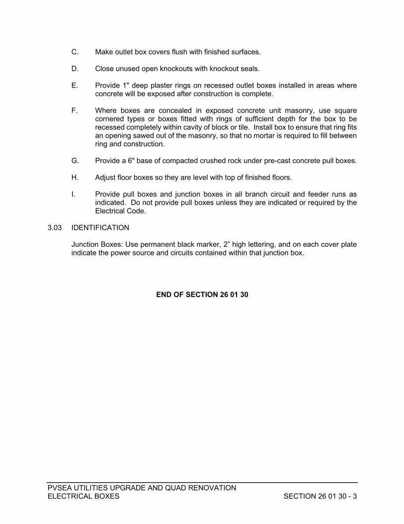
PVSEA UTILITIES UPGRADE AND QUAD RENOVATION ELECTRICAL BOXES SECTION 26 01 30 - 3
C. Make outlet box covers flush with finished surfaces.
D. Close unused open knockouts with knockout seals.
E. Provide 1" deep plaster rings on recessed outlet boxes installed in areas where concrete will be exposed after construction is complete.
F. Where boxes are concealed in exposed concrete unit masonry, use square
cornered types or boxes fitted with rings of sufficient depth for the box to be recessed completely within cavity of block or tile. Install box to ensure that ring fits an opening sawed out of the masonry, so that no mortar is required to fill between ring and construction.
G. Provide a 6" base of compacted crushed rock under pre-cast concrete pull boxes.
H. Adjust floor boxes so they are level with top of finished floors.
I. Provide pull boxes and junction boxes in all branch circuit and feeder runs as
indicated. Do not provide pull boxes unless they are indicated or required by the Electrical Code.
3.03 IDENTIFICATION
Junction Boxes: Use permanent black marker, 2” high lettering, and on each cover plate indicate the power source and circuits contained within that junction box.
END OF SECTION 26 01 30

PVSEA UTILITIES UPGRADE AND QUAD RENOVATION TERMINAL CABINETS SECTION 26 01 33 - 1
SECTION 26 01 33 TERMINAL CABINETS
PART 1 GENERAL 1.01 DESCRIPTION
A. Division 1 and Section 260050 apply to this Section. Provide terminal cabinets for signal and communications terminals, complete.
B. Related Work Not In This Section: 1. Outlet, pull, and junction boxes. 2. Panelboards for lighting and power. PART 2 PRODUCTS 2.01 MATERIALS Cold rolled sheet steel, with hinged door and cylinder lock keyed to match panelboard
cabinets. 2.02 DESIGN To suit applicable system requirements; surface or flush-mounting as shown; knockouts
as required. Design to match panelboard cabinets. 2.03 FABRICATION One-piece, die-formed or continuously welded, and assembled in factory. 2.04 FINISH Baked enamel on a suitable primer; color as specified elsewhere, required by standards,
or as directs. 2.05 INTERIORS Provide 5/8" plywood (fire resistant) backing in all signal and communications terminals. PART 3 EXECUTION 3.01 INSTALLATION Secure and substantial, cabinets attached to building walls or structure.
PVSEA UTILITIES UPGRADE AND QUAD RENOVATION TERMINAL CABINETS SECTION 26 01 33 - 2
3.02 IDENTIFICATION Provide identification nameplates; of engraved bakelite; riveted or screwed to each
cabinet. Take text from Drawings and as approved by Architect.
END OF SECTION 26 01 33

PVSEA UTILITIES UPGRADE AND QUAD RENOVATION WIRING DEVICES SECTION 26 01 40 - 1
SECTION 26 01 40 WIRING DEVICES
PART 1 GENERAL 1.01 SECTION INCLUDES
Wiring devices.
1.02 RELATED WORK SPECIFIED ELSEWHERE
A. Identification: Section 260030. B. Boxes: Section 260130.
1.03 SUBMITTALS
In accord with Section 260010.
1.04 DEFINITION
Wiring devices: This term includes all wall switches, pushbuttons, receptacles, and plates used for general purpose installation.
PART 2 PRODUCTS 2.01 MATERIAL AND FABRICATION
A. Wall switches: 1. Quiet toggle type, 20A – 120/277 VAC rated, with terminal screws to take
up to No. 10 AWG conductors:
SPST
DPST
3-WAY
SPST KEY SWITCH LOCK
4-WAY Arrow-Hart 1991-I 1992-I 1993-I 1991-L 1994-I Bryant 4901-I 4902-I 4903-I 4901-L 4904-I General Electric GE5951-2 GE5952-2 GE5953-2 GE5951-OL GE5954-2
Hubbell 1221-I 1222-I 1223-I 1221-L 1224-I Pass & Seymour/ Legrand
20AC1-I
20AC2-I
20AC3-I
20AC1-L
20AC4-I
2. Momentary contact type, 20A-120/277V, two-circuit, three-position, center off:

PVSEA UTILITIES UPGRADE AND QUAD RENOVATION WIRING DEVICES SECTION 26 01 40 - 2
Arrow-Hart 1995-I
Bryant
4921-I
General Electric GE5935-2 Hubbell 1557-I Pass & Seymour/Legrand 1250-I
3. Passive infrared wall switch sensors: Ivory, 180° field of view, adjustable
time out and ambient light, 1200 sq. ft. Coverage, 120 VAC, 60 Hz, 1500W. Maximum load, incandescent and fluorescent. As manufactured by Hubbell No. AT1201 or Owner- approved equivalent by Leviton or Pass & Seymour.
4. Fan speed controllers: AC unit rated 15A - 120V used to control up to twelve 56 in./52 in./48 in. ceiling fans or up to twenty 42 in. fans on a single circuit. Rinaudo's Reproductions No. 22394.
B. Passive infrared motion switching system: 1. Ceiling mount sensor, white, 500 sq. ft. coverage, requires control unit.
Hubbell No. ATD500CRP. 2. Ceiling mount sensor, white, 2000 sq. ft. coverage, ceiling height
dependent, requires control unit. Hubbell No. ATD2000CRP. 3. Ceiling or wall mount sensor, white, 1000 sq. ft. coverage, requires
control unit. Hubbell No. ATD1000CRP. 4. Ceiling or wall mount hallway sensor, white, covers area 75 ft. long by 20
ft. wide, requires control unit. Hubbell No. PIR90HW1. 5. Low-voltage control unit, 120VAC, controls one to four sensors. Mount in
4 in. x 4in. enclosure. Hubbell No. CU120A. 6. Relay, 120VAC coil, used when load to be controlled exceeds capacity of
a single circuit. Hubbell No. AAR
C. Receptacles, caps, and connectors: 1. 15A-125V, NEMA 5-15, parallel slot type with grounding pin:
DUPLEX SINGLE GFI Arrow-Hart 5252-I 5261-I GF5242-I Bryant 5252-I 5261-I GFR52FT General Electric 5252-2 5261-2 TGTR115F Hubbell 5252-I 5251-I GF5252-I Pass & Seymour/Legrand
5252-I 5261-I 1591-SHG
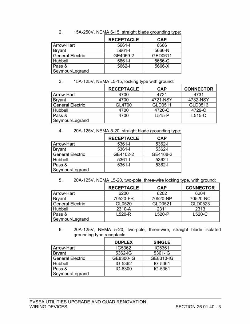
PVSEA UTILITIES UPGRADE AND QUAD RENOVATION WIRING DEVICES SECTION 26 01 40 - 3
2. 15A-250V, NEMA 6-15, straight blade grounding type: RECEPTACLE CAP Arrow-Hart 5661-I 6666 Bryant 5661-I 5666-N General Electric GE4069-2 GED0611 Hubbell 5661-I 5666-C Pass & Seymour/Legrand
5662-I 5666-X
3. 15A-125V, NEMA L5-15, locking type with ground:
RECEPTACLE CAP CONNECTOR Arrow-Hart 4700 4721 4731 Bryant 4700 4721-NSY 4732-NSY General Electric GL4700 GLD0511 GLD0513 Hubbell 4700 4720-C 4729-C Pass & Seymour/Legrand
4700 L515-P L515-C
4. 20A-125V, NEMA 5-20, straight blade grounding type:
RECEPTACLE CAP Arrow-Hart 5361-I 5362-I Bryant 5361-I 5362-I General Electric GE4102-2 GE4108-2 Hubbell 5361-I 5362-I Pass & Seymour/Legrand
5361-I 5362-I
5. 20A-125V, NEMA L5-20, two-pole, three-wire locking type, with ground:
RECEPTACLE CAP CONNECTOR Arrow-Hart 6200 6202 6204 Bryant 70520-FR 70520-NP 70520-NC General Electric GL0520 GLD0521 GLD0523 Hubbell 2310-A 2311 2313 Pass & Seymour/Legrand
L520-R L520-P L520-C
6. 20A-125V, NEMA 5-20, two-pole, three-wire, straight blade isolated
grounding type receptacle: DUPLEX SINGLE Arrow-Hart IG5362 IG5361 Bryant 5362-IG 5361-IG General Electric GE8300-IG GE8310-IG Hubbell IG-5362 IG-5361 Pass & Seymour/Legrand
IG-6300 IG-5361
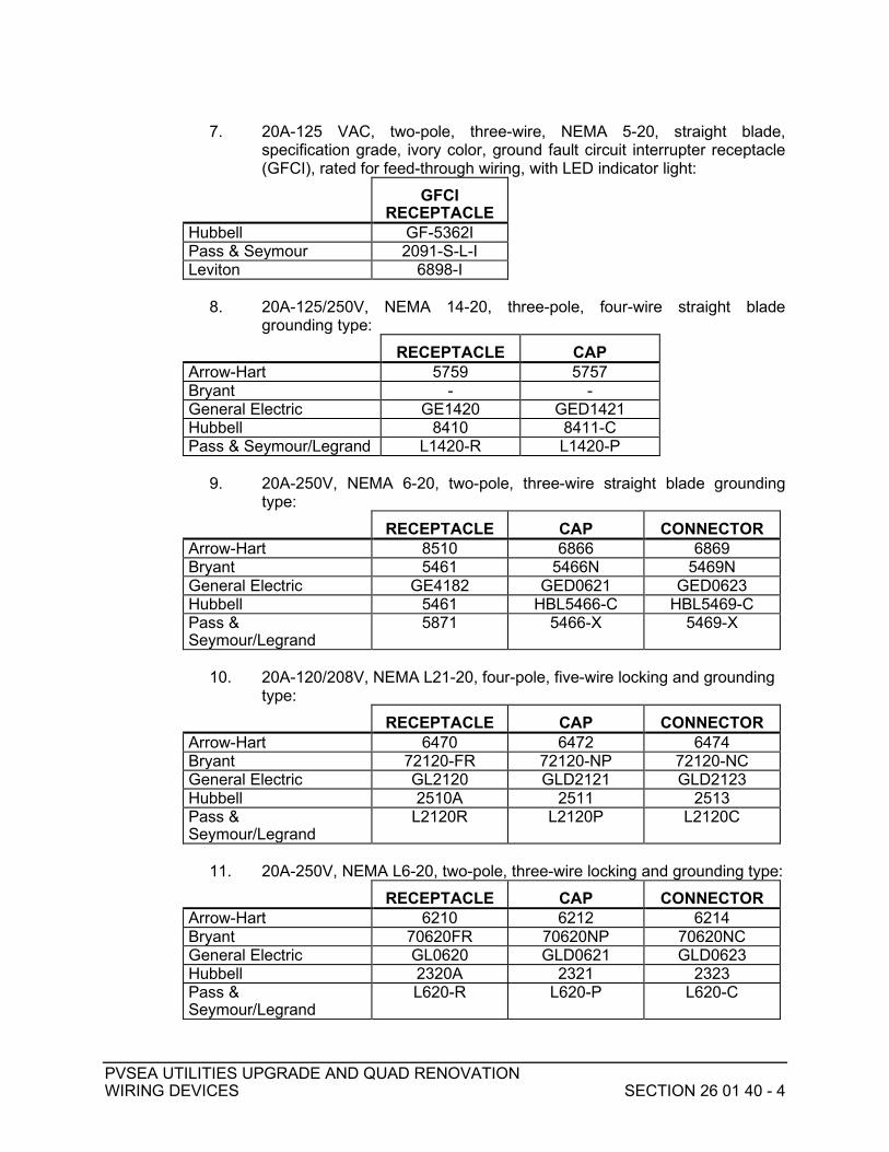
PVSEA UTILITIES UPGRADE AND QUAD RENOVATION WIRING DEVICES SECTION 26 01 40 - 4
7. 20A-125 VAC, two-pole, three-wire, NEMA 5-20, straight blade,
specification grade, ivory color, ground fault circuit interrupter receptacle (GFCI), rated for feed-through wiring, with LED indicator light:
GFCI RECEPTACLE
Hubbell GF-5362I Pass & Seymour 2091-S-L-I Leviton 6898-I
8. 20A-125/250V, NEMA 14-20, three-pole, four-wire straight blade
grounding type: RECEPTACLE CAP Arrow-Hart 5759 5757 Bryant - - General Electric GE1420 GED1421 Hubbell 8410 8411-C Pass & Seymour/Legrand L1420-R L1420-P
9. 20A-250V, NEMA 6-20, two-pole, three-wire straight blade grounding
type: RECEPTACLE CAP CONNECTOR Arrow-Hart 8510 6866 6869 Bryant 5461 5466N 5469N General Electric GE4182 GED0621 GED0623 Hubbell 5461 HBL5466-C HBL5469-C Pass & Seymour/Legrand
5871 5466-X 5469-X
10. 20A-120/208V, NEMA L21-20, four-pole, five-wire locking and grounding
type: RECEPTACLE CAP CONNECTOR Arrow-Hart 6470 6472 6474 Bryant 72120-FR 72120-NP 72120-NC General Electric GL2120 GLD2121 GLD2123 Hubbell 2510A 2511 2513 Pass & Seymour/Legrand
L2120R L2120P L2120C
11. 20A-250V, NEMA L6-20, two-pole, three-wire locking and grounding type:
RECEPTACLE CAP CONNECTOR Arrow-Hart 6210 6212 6214 Bryant 70620FR 70620NP 70620NC General Electric GL0620 GLD0621 GLD0623 Hubbell 2320A 2321 2323 Pass & Seymour/Legrand
L620-R L620-P L620-C
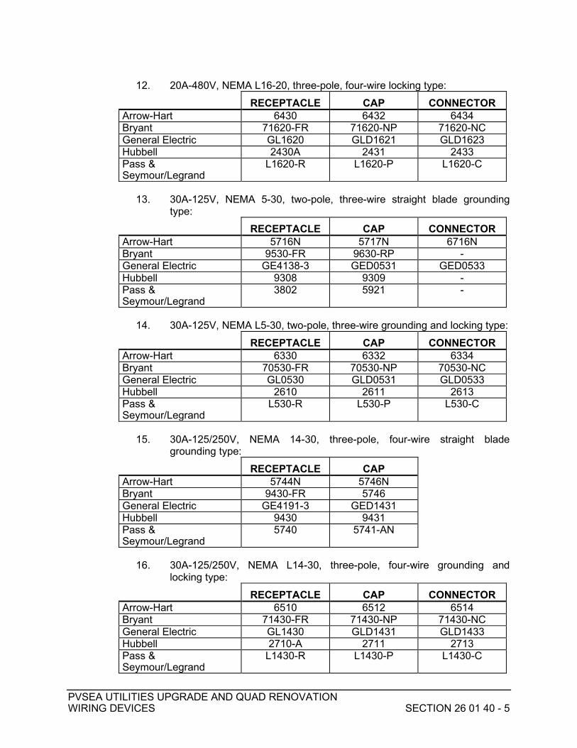
PVSEA UTILITIES UPGRADE AND QUAD RENOVATION WIRING DEVICES SECTION 26 01 40 - 5
12. 20A-480V, NEMA L16-20, three-pole, four-wire locking type:
RECEPTACLE CAP CONNECTOR Arrow-Hart 6430 6432 6434 Bryant 71620-FR 71620-NP 71620-NC General Electric GL1620 GLD1621 GLD1623 Hubbell 2430A 2431 2433 Pass & Seymour/Legrand
L1620-R L1620-P L1620-C
13. 30A-125V, NEMA 5-30, two-pole, three-wire straight blade grounding
type: RECEPTACLE CAP CONNECTOR Arrow-Hart 5716N 5717N 6716N Bryant 9530-FR 9630-RP - General Electric GE4138-3 GED0531 GED0533 Hubbell 9308 9309 - Pass & Seymour/Legrand
3802 5921 -
14. 30A-125V, NEMA L5-30, two-pole, three-wire grounding and locking type:
RECEPTACLE CAP CONNECTOR Arrow-Hart 6330 6332 6334 Bryant 70530-FR 70530-NP 70530-NC General Electric GL0530 GLD0531 GLD0533 Hubbell 2610 2611 2613 Pass & Seymour/Legrand
L530-R L530-P L530-C
15. 30A-125/250V, NEMA 14-30, three-pole, four-wire straight blade
grounding type: RECEPTACLE CAP Arrow-Hart 5744N 5746N Bryant 9430-FR 5746 General Electric GE4191-3 GED1431 Hubbell 9430 9431 Pass & Seymour/Legrand
5740 5741-AN
16. 30A-125/250V, NEMA L14-30, three-pole, four-wire grounding and
locking type: RECEPTACLE CAP CONNECTOR Arrow-Hart 6510 6512 6514 Bryant 71430-FR 71430-NP 71430-NC General Electric GL1430 GLD1431 GLD1433 Hubbell 2710-A 2711 2713 Pass & Seymour/Legrand
L1430-R L1430-P L1430-C

PVSEA UTILITIES UPGRADE AND QUAD RENOVATION WIRING DEVICES SECTION 26 01 40 - 6
17. 30A-250V, NEMA L6-30, two-pole, three-wire locking blade grounding type:
RECEPTACLE CAP CONNECTOR Arrow-Hart 6340 6342 6344 Bryant 70630-FR 70630-NP 70630-NC General Electric GL0630 GLD0631 GLD0633 Hubbell 2620-A 2621 2623 Pass & Seymour/Legrand
L630-R L630-P L630-C
18. 30A-250V, NEMA 6-30, two-pole, three-wire straight blade grounding
type: RECEPTACLE CAP CONNECTOR Arrow-Hart 5700N 5701N 6700N Bryant 9630-FR 9630-ANP - General Electric GE4139-3 GE4328-9 GE4373-9 Hubbell 9330 9331 - Pass & Seymour/Legrand
3801 5931 -
19. 50A-208V (50A-600V), three-pole, four-wire locking type with ground:
RECEPTACLE CAP CONNECTOR Arrow-Hart 3769 3765 3764 Bryant 3769 3765 3764 General Electric LD3769 LD3765 LD3764 Hubbell 3769 3765-C 3764-C Pass & Seymour/Legrand
3769 3765 3764
20. 50A-125/250V, NEMA 15-50, three-pole, four-wire grounding straight
blade type: RECEPTACLE CAP Arrow-Hart 5754N 5745N Bryant 9450-FR 5745 General Electric GE4181-3 GE4180-3 Hubbell 9450 9451 Pass & Seymour/Legrand
5750 5751-AN
21. 50A-125/250V, three-pole, four-wire grounding locking blade type:
RECEPTACLE CAP CONNECTOR Arrow-Hart CS6369 CS6365 CS6364 Bryant CS6369 CS6365 CS6364 General Electric - - - Hubbell CS6369 CS6365 CS6364 Pass & Seymour/Legrand
- - -

PVSEA UTILITIES UPGRADE AND QUAD RENOVATION WIRING DEVICES SECTION 26 01 40 - 7
22. 50A-250V, NEMA 6-50, two-pole, three-wire grounding straight blade type:
RECEPTACLE CAP CONNECTOR Arrow-Hart 5709N 5710N 6709N Bryant 9650-FR 9650-RP - General Electric GE4141-3 GED0651 GED0653 Hubbell 9367 9368 - Pass & Seymour/Legrand
3804 3869 -
23. 60A-120/208V, three-phase, 60 Hz, five-pole, five-wire, watertight, with
threaded cap:
BOX ANGLE
ADAPTER RECEPTACL
E BODY COMPLETE ASSEMBLY
Hubbell 26401 26404 26520 - Crouse-Hinds - - - Area-6575 Russell Stoll - - - DS6516-FRAB-
24. 60A-480V, NEMA L16-20, three-pole, four-wire locking type:
RECEPTACLE CAP CONNECTOR Arrow-Hart - - - Bryant - - - General Electric - - - Hubbell HBL 26410 HBL 26402 HBL 26418 Pass & Seymour/Legrand
- - -
D. Safety receptacle: 15A-125V, NEMA 5-15, straight blade grounding safety
receptacle, Hubbell No. SG-62H-1. E. Door monitoring switches:
1. General: Provide magnetic door switches (one per leaf) and key switches at specific door locations as indicated on Drawings. Refer to Electrical Drawings details for schematic installation details of door switches.
2. Magnetic contact switches: Provide concealed magnetic SPDT switches with minimum 6-ft. wire leads, Sentrol No. 1076W-06 for hollow metal doors and frames. Where necessary, provide other similar Sentrol types to suit concealed installation conditions, as approved by Owner and compatible with Owner's ride control and/or existing security system equipment. Color of switches to closely match finish or paint color of door frame.
3. Key switches: Arrow-Hart No. 1191L.
F. Device cover plates: 1. Interior plates: Specification grade plastic, 0.1 in. thick, ivory in color, UL
listed. a. Plates in kitchens and restrooms to be polished stainless steel,
0.040 in. thick except in kitchens use double lift lid weatherproof gasketed plates for convenience receptacles.

PVSEA UTILITIES UPGRADE AND QUAD RENOVATION WIRING DEVICES SECTION 26 01 40 - 8
b. MATV plate: RMS No. CA-4028. 2. Exterior plates: Choose type of exterior cover plate in accord with the
device location and/or manner in which device will be used. Device cover plates shall be die-cast aluminum with hinged cover, rated for respective type of use specified below, or as indicated on Drawings. a. Outlet box weatherproof hoods: NEMA 3R rating, gasketed, for
unattended use with cover closed, padlockable latching cover to meet OSHA lockout/tagout requirements, large cord opening, and UL listed. As manufactured by Hubbell, Intermatic or Leviton.
b. Low profile weatherproof cover: Gasketed, approved for use with cover open, self-closing hinged covers (two independent self-closing lids for duplex receptacles which are horizontally mounted), UL listed. As manufactured by Hubbell, Leviton, or Pass & Seymour.
c. Communication outlet weatherproof hoods: NEMA 3R rating for unattended use with cover closed, two-cord openings and UL listed. As manufactured by Red Dot.
PART 3 EXECUTION 3.01 INSTALLATION
A. Mount switches and receptacles in vertical position in building interiors. B. Mount receptacles with weatherproof plates in horizontal position. C. Install receptacles mounted vertically so that the ground contact falls on the top
position, and horizontally-mounted receptacles with neutral pole in top position.
D. Use plastic blank plates on J-boxes in public areas.
E. Use mechanical type door switches for load control.
F. Install receptacles for plug in lighting fixtures within 36 in. of fixture location.
G. Use safety type receptacles with low profile weatherproof metal covers for all convenience outlets in guest accessible areas (i.e., queue lines, waiting areas, etc.).
H. All GFI type exterior receptacles shall be provided with weatherproof metal
hoods.
I. GFI type receptacles shall not be fed-through wire.
END OF SECTION 26 01 40

PVSEA UTILITIES UPGRADE AND QUAD RENOVATION NAMEPLATES AND WARNING SIGNS SECTION 26 01 42 - 1
SECTION 26 01 42 NAMEPLATES AND WARNING SIGNS
PART 1 GENERAL
(Not Used) PART 2 PRODUCTS 2.01 NAMEPLATES A. Nameplate shall be plastic laminate with 3/4" high letters in white on black
background screwed onto equipment designations shall clearly state: 1. Equipment Enclosure Nameplates.
a. Manufacturer's nameplate including equipment design rating of current, voltage, KVA, HP, bus bracing rating, or as applicable.
b. Equipment nameplate designating system usage and purpose, system nominal voltage, equipment rating for KVA, amperes, HP, and RPM as applicable. Designation data per drawings or to be supplied with shop drawings approval.
2. Device nameplates: Device usage, purpose, or circuit number; manufacturer and electrical characteristic ratings including the following:
a. Circuit Breakers: Voltage, continuous current, maximum interrupting current and trip current.
b. Switches: Voltage, continuous current, horsepower or maximum current switching. If fused, include nameplate stating, "Fuses must be replaced with current limiting type of identical characteristics."
c. Contactors: Voltage, continuous current, horsepower or interrupting current, and whether "mechanically-held" or "electrically-held".
d. Motors: Rated voltage, full load amperes, frequency, phases, speed, horsepower, code letter rating, time rating, type of winding, class, and temperature.
e. Controllers: Voltage, current, horsepower and trip setting of motor running over current protection.
2.02 WARNING SIGNS
Warning signs shall be minimum 18 gauge steel, white porcelain enamel finish with red lettering. Lettering to read "DANGER - HIGH VOLTAGE" in 1" letters. Warning signs to be included on door or immediately above door of all electrical equipment rooms, vaults or closets containing equipment rooms, vaults or closets containing equipment energized above 150 volts to ground, except where such spaces are accessible from public areas.
2.03 WARNING SIGN DESIGNATION
Warning designation in 1" red letters shall be painted by stencil or pre-printed adhesive on each pull box, cabinet or 1-foot length of exposed conduit stating "DANGER" and giving voltage of enclosed conductors such as "DANGER - 480 VOLTS", for all systems over 150 volts to ground.

PVSEA UTILITIES UPGRADE AND QUAD RENOVATION NAMEPLATES AND WARNING SIGNS SECTION 26 01 42 - 2
PART 3 EXECUTION 3.01 INSTALLATION A. Nameplates shall be mounted by self-tapping or threaded screws and bolts or by
rivets. B. Signs shall be permanently mounted with cadmium plated steel screws or nickel-
plated brass bolts.
END OF SECTION 26 01 42
PVSEA UTILITIES UPGRADE AND QUAD RENOVATION DISTRIBUTION PANELBOARDS SECTION 26 01 63 - 1
SECTION 26 01 63 DISTRIBUTION PANELBOARDS
PART 1 GENERAL 1.01 WORK INCLUDED
Distribution panelboards. 1.02 RELATED WORK SPECIFIED ELSEWHERE
A. Submittals: Section 260000.
B. Overcurrent Protective Devices: Section 260180.
C. Disconnects: Section 260170.
D. Control Devices: Section 264901. PART 2 PRODUCTS 2.01 MATERIAL AND FABRICATION
A. Provide distribution panelboards with molded case breakers or fused switches for mains and feeders as indicated. All equipment shall be listed to meet or exceed the available short circuit current.
B. Provide full length copper bussing including areas indicated as space only.
C. Provide full size neutral bus where neutral bus is indicated.
D. Provide copper ground bus adequate for number of grounded circuits.
E. Circuit Breaker Type: Square-D Co. I-Line, with alternate bid for General Electric
type AV Line. F. All circuit breakers shall be capable of being locked in the off position. PART 3 EXECUTION 3.01 INSTALLATION
A. Secure panelboards to structures to withstand wire pulling strains.
B. Secure surface mounted panelboards to wood studs or channel material spanning metal studs.

PVSEA UTILITIES UPGRADE AND QUAD RENOVATION DISTRIBUTION PANELBOARDS SECTION 26 01 63 - 2
C. Do not use toggle bolts to wall mount units.
D. Floor mounted units shall be on 4-inch concrete housekeeping pads. E. Secure to structure per seismic requirements. 3.02 LABELING AND IDENTIFICATION
A. Provide engraved plastic nameplates on all distribution panelboards shown on the single line diagram.
B. Provide panelboard and source feed designation on nameplates with minimum 3/8"
lettering for the panel name and 3/4" height lettering for the source feed designation.
EXAMPLE: DLA FED FROM: T-2
C. Provide engraved plastic nameplates with 1/4" minimum height letters at all branch
overcurrent devices indicating the circuit designating and the load served.
D. Secure nameplates with at least two screws or rivets. Cementing and adhesive installation not acceptable.
END OF SECTION 26 01 63

PVSEA UTILITIES UPGRADE AND QUAD RENOVATION BRANCH CIRCUIT PANELBOARDS SECTION 26 01 64 - 1
SECTION 26 01 64 BRANCH CIRCUIT PANELBOARDS
PART 1 GENERAL 1.01 WORK INCLUDED
Branch circuit panelboards. 1.02 RELATED WORK SPECIFIED ELSEWHERE
A. Submittals: Section 260000.
B. Overcurrent Protective Devices: Section 260180.
C. Control Devices: Section 264901. PART 2 PRODUCTS 2.01 MATERIAL AND FABRICATION
A. Provide factory assembled, enclosed panelboards in dead front cabinets, with doors, surface mounted or recessed as indicated, not less than 20" wide and 5-3/4" deep. Height will depend on the number of breakers and spaces.
B. Where a control compartment is indicated, provide an integral compartment with a separate
hinged lockable door held with captive screws. Identify all internal control wiring with manufacturers wire numbering or control wire numbering when indicated, at all terminal points and connections.
C. Provide feeder terminal lugs for both main lugs only and main breakers rated for use with
copper conductors.
D. Provide full length copper bussing including areas indicated as space only.
E. Provide full size neutral bus where neutral bus is indicated. Provide equipment ground bus and bolt-on circuit breakers.
F. Key all door locks alike.
G. 120/208V, 3 Phase, 4 Wire Panelboards: Square-D Co. Type NQOD or Powerlink G3 NF
with programmable module where designated, alternate bid for General Electric type AQ.
H. 277/480V, 3 Phase, 4 Wire Panelboards: Square-D Co. Type NF, alternate bid for General Electric type CCB.
I. All equipment shall be listed to meet or exceed the available fault current by 10%. J. Doors shall be hinged. K. All placards are welded steel type.

PVSEA UTILITIES UPGRADE AND QUAD RENOVATION BRANCH CIRCUIT PANELBOARDS SECTION 26 01 64 - 2
PART 3 EXECUTION 3.01 INSTALLATION
A. Secure panelboards to building structure to withstand wire pulling strains.
B. Secure surface mounted panelboards to wood studs or channel material spanning metal studs.
C. Do not use toggle bolts.
D. Contractor shall program lighting control Powerlink panelboard per owner’s requirements.
3.02 LABELING AND IDENTIFICATION
A. Provide engraved plastic nameplates on all branch circuit panelboards shown on the single line diagram.
B. Provide panelboard and source feed designation on nameplates with 3/8" minimum height
lettering for the panel name and 1/4" height lettering for the source feed designation.
EXAMPLE: LA FED FROM: DLA
C. Secure nameplates with at least two spaces or rivets. Cementing and adhesive installation
not acceptable.
D. Provide a typewritten directory for each branch circuit panelboard, showing each circuits and its use. Provide metal directory frame with plastic window.
END OF SECTION 26 01 64

PVSEA UTILITIES UPGRADE AND QUAD RENOVATION DISCONNECTS SECTION 26 01 70 - 1
SECTION 26 01 70 DISCONNECTS
PART 1 GENERAL 1.01 WORK INCLUDED
Disconnects: Switches, fused or unfused. 1.02 RELATED WORK SPECIFIED ELSEWHERE
A. Submittals: Section 260010.
B. Fuses: Section 260180. PART 2 PRODUCTS 2.01 ACCEPTABLE MANUFACTURERS
A. Square D Company B. General Electric
2.02 MATERIAL AND FABRICATION
A. Provide heavy duty type, quick-make, quick-break disconnects with cover interlocks.
B. Provide NEMA Type 1 enclosure for dry locations, provide the proper enclosure for other locations as indicated.
C. Provide motor rated toggle switches where indicated.
D. Provide fused disconnect for elevator drive motors.
E. Provide rejection clips on disconnects where rejection type fuses are to be installed.
PART 3 EXECUTION 3.01 INSTALLATION
Securely fasten disconnects to structure to withstand wire pulling strains. 3.02 LABELING AND IDENTIFICATION
A. Provide engraved plastic nameplates on individually mounted disconnects with minimum 1/4" height letters indicating the load served and the source feed designation.
EXAMPLE: LOAD: A/C-1
FED FROM: DHA-1
B. Secure nameplates with at least two screws or rivets. Cementing and adhesive installation not acceptable.
END OF SECTION 26 01 70
PVSEA UTILITIES UPGRADE AND QUAD RENOVATION SUPPORT DEVICES SECTION 26 01 90 - 1
SECTION 26 01 90 SUPPORT DEVICES
PART 1 GENERAL 1.01 WORK INCLUDED
Support devices for conduit, boxes, lighting fixtures and equipment. PART 2 PRODUCTS 2.01 ACCEPTABLE MANUFACTURERS
A. Hangers, Straps and Beam Clamps: 1. Efcor. 2. Raco, Inc. 3. Steel City. 4. O.Z./Gedney Co. 5. Caddy Fastening System by ERICO Products Inc.
B. Channels and Fittings:
1. Kindorf. 2. Unistrut Corp.
C. Anchors:
1. Acherman-Johnson Corp. 2. Phillips Drill Co. 3. Rawl Products Co.
2.02 MATERIAL AND FABRICATION
A. Hangers: Steel cadmium plated.
B. Straps: One-hole and two-hole malleable iron, hot-dipped galvanized or steel, cadmium or zinc plated.
C. Beam Clamps: Malleable iron, hot-dipped galvanized or cadmium plated.
D. Channels and Fittings:
1. Channels: Hot-dipped galvanized. 2. Fittings: Galvanized.
E. Anchors: Self drilling and expansion bolt types. No wood or fiber plugs or concrete
nails are acceptable.

PVSEA UTILITIES UPGRADE AND QUAD RENOVATION SUPPORT DEVICES SECTION 26 01 90 - 2
PART 3 EXECUTION 3.01 USE
A. Use one-hole or two-hole straps for single conduit runs on walls or ceilings.
B. Use hangers with solid steel rods for hanging single conduits.
C. Use formed channel trapezes for groups of two or more conduits.
D. To fasten boxes and supports to: 1. Wood: Use wood screws or screw type nails of equal holding power. 2. Brick and Concrete: Use bolts and expansion shields. 3. Hollow Masonry Units: Use toggle bolts.
E. Support sheet metal boxes from building structure directly or by bar hangers.
F. Do not penetrate reinforced concrete beams with fastenings more than 1-1/2" or
reinforced concrete joints with more than 3/4" fastenings to prevent contact with reinforcing steel.
END OF SECTION 26 01 90
PVSEA UTILITIES UPGRADE AND QUAD RENOVATION GROUNDING SECTION 26 24 50 - 1
SECTION 26 24 50 GROUNDING
PART 1 GENERAL 1.01 REFERENCES
A. N.E.C.: Article 250 "Grounding".
B. Underwriter's Laboratories (U.L.). Standard A67 - "Grounding and Bonding Equipment". STD 869 - Grounding and Bonding.
C. ITEE - Standards 142 and 241.
1.02 DESCRIPTION OF SYSTEM A permanent grounding system with methods and materials in accordance with applicable
Codes and Standards, able to conduct ground fault currents to the grounded neutral of electrical distribution systems, and limit potential differences between grounding conductors, raceways, and enclosures.
1.03 SUBMITTALS
A. Product Data: Submit manufacturer's data on grounding systems and accessories.
B. Shop Drawings: Submit layout drawings of grounding systems and accessories including, but not limited to, ground wiring, copper braid and bus, ground rods, and plate electrodes.
1.04 QUALITY ASSURANCE Installer qualifies with at least 3 years of successful installation experience on projects with
electrical grounding experience similar to that required for project. 1.05 DELIVERY, STORAGE, AND HANDLING Handle electrical grounding accessories and components carefully to avoid damage. Store
in location that will protect from dirt and weather. PART 2 PRODUCTS 2.01 GROUND RODS Copper clad steel, unless indicated otherwise. Minimum dimension of 5/8" diameter by 8'
long or larger if indicated and sectional rods with couplings where lengths exceeding 12' are specified or indicated, or where added driving depth is required to achieve a specified minimum resistance.

PVSEA UTILITIES UPGRADE AND QUAD RENOVATION GROUNDING SECTION 26 24 50 - 2
2.02 GROUNDING ELECTRODE Bare stranded copper, 3/0 AWG unless indicated otherwise, for installation in soil or
embedded in concrete and cable with type TW insulation when installed in raceway. Install without splice from connection to connection.
2.03 GROUNDING CONDUCTORS Type TW insulation, unless specified or indicated otherwise with a continuous green outer
insulating jacket for size #6 AWG and smaller and with green tape banding for #4 AWG and larger, marked at each access point (e.g.: Junction boxes, Enclosures).
2.04 CLAMPS AND PRESSURE CONNECTORS Cast copper, copper alloy, or bronze alloy suitable for use with aluminum and copper.
Double bolt type with formed shoe and "U" cable clamp for connection to pipe or conduit; Single bolt type with cable shoe and "U" clamp for connections to flat bar or metal; and double bolt, parallel conductor split clamp type for cable to cable connections.
2.05 WELDED CONNECTIONS Exothermic process (Cadweld or Thermoweld). 2.06 EQUIPMENT ROOM GROUND TERMINAL BAR Copper 1/4" X 2-1/2" X 24", unless otherwise indicated. Two rows of holes on 1-1/2"
centers for 1/2" bolt, to receive cables from two directions. PART 3 EXECUTION 3.01 GENERAL Ground conductive raceways, cable trays and enclosures for electrical systems wiring.
Make ground circuits complete to form permanent conductive paths. Solidly ground each low voltage electrical system unless indicated or specified as ungrounded or grounded through an impedance of a specified value. Provide bare conductors when in open air or soil and provide 600 volt, green, insulated conductors when in raceway.
3.02 MAIN GROUNDING JUMPER A. Install a main grounding jumper between the system neutral and the enclosure
ground bus (or directly to enclosure where ground bus is not present) at each location where system grounding is required. Main grounding jumper:
1. Formed bus in switchboards and panelboards. 2. Formed bus or copper cable in transformers not coupled in unitized
assembly with distribution equipment.

PVSEA UTILITIES UPGRADE AND QUAD RENOVATION GROUNDING SECTION 26 24 50 - 3
3.03 GROUND CONNECTIONS Make grounding electrode connections electrically ahead of any overcurrent or disconnect
device or tap connection such that disconnection of neutral load conductors does not interfere with or remove the system ground connection. Use separate lugs on the transformer neutral terminals for neutral and main grounding jumpers when cable is used for transformer connections.
3.04 SEPARATELY DERIVED SYSTEMS For each separately derived system, grounded or ungrounded, install a grounding electrode
conductor between each system enclosure ground bus (or bolted connection to enclosure where ground bus is not present) and a cold water pipe or building structural steel of one (1) inch size or larger near the separately derived system ground connection. Make connections to water pipes or steel accessible for easy inspection. Provide a separate ground conductor for each audio, video, isolated panels, and UPS as noted on the plans.
3.05 SERVICE GROUND
For each low voltage service, install a grounding electrode conductor between the system enclosure ground bus and the water service entrance to the building and install bonding jumpers around insulating unions and removable fittings in the water pipe between the grounding electrode conductor connection to the water pipe and the water service entrance.
3.06 GROUNDING ELECTRODE SYSTEM A. Install a complete grounding electrode system with interconnecting cables and
terminations at the equipment room ground terminal bar. Make connections to the grounding electrode system accessible. Install the following grounding electrode systems:
1. Metal frame of building. 2. Grounding electrode encased by at least two inches of concrete, within and
near the bottom of the building foundation or footing of the type specified in Part 2 - Products, at least 20 feet in length without splice from connection to connection.
3. Connection of other metal piping systems as required by National Electrical Code Article 250.
4. Driven ground rods. 5. Driven steel piles. 6. Connection to water service with bonding jumper around water meter.
3.07 GROUNDING ELECTRODE CONDUCTORS Install grounding electrode conductor in PVC or other non-conductive, non-metallic
enclosure where a raceway system is indicated or necessary for conductor installation. Install grounding electrode conductors without splice from the enclosure ground bus to the connection at the grounding electrode system.

PVSEA UTILITIES UPGRADE AND QUAD RENOVATION GROUNDING SECTION 26 24 50 - 4
3.08 GROUND RODS Install a vertical position, full length below grade unless specified otherwise, and with
conductor and top of rod 6" minimum below grade. Provide exotheric welds at all connections.
3.09 EQUIPMENT ROOM GROUND TERMINAL BAR Install in equipment rooms where indicated. Mount bar by anchors and bolts using 1-1/2"
long segments of 1/2" rigid conduit as spacer between bar and wall. Use a minimum of two supports, 18" on center. Connect grounding electrode system conductors, system enclosure ground bus, and other indicated electrode systems to the terminal bar. Label permanently all ground conductors as to destination location, e.g. TR1, panel IPS, etcetera.
3.10 EQUIPMENT GROUND Form the equipment ground circuits with rigid metallic raceways (e.g., EMT, rigid steel
conduit) unless indicated otherwise. Make all threaded coupling connections wrench tight. Install bonding jumpers for continuity around fittings and terminations where the conductive raceway is made non-continuous. Where indicated or specified, install ground conductors in raceways to augment the circuits formed by the metallic raceway system. Bond the conductors to boxes or enclosures in which access is possible. Size conductors as specified, indicated, or required by code, whichever is larger. Install grounding bushings and bonding jumpers to enclosures or ground bussing for the following: Service entrance feeder; each location where multiple ring knockouts are damaged during conduit installation; each location where conduits are stubbed up into floor mounted and each conduit termination at a painted enclosure where paint is not removed before installation of raceway.
3.11 FLEXIBLE RACEWAY GROUNDING Install a ground conductor inside all flexible raceways (e.g., Flexible steel, liquid tight)
regardless of length. Bond the conductor to the enclosure or ground bus in the nearest box or access on either side of the flexible section. Size conductor as specified, indicated, or required by code, whichever is larger.
3.12 NON-CONDUCTIVE RACEWAY Install a ground conductor in raceways of non-conductive materials. Bond conductor to
conductive enclosures in which access is possible. Bond non-current carrying conductive equipment contained in a non-conductive enclosure. Install insulated or bare conductors, sized as specified, indicated, or required by code, whichever is larger.

PVSEA UTILITIES UPGRADE AND QUAD RENOVATION GROUNDING SECTION 26 24 50 - 5
3.13 SECTIONAL RACEWAY Install a ground conductor in sectional raceways with removable covers for access (e.g.,
Plug-in strips, surface raceway systems, and wireways) unless specified otherwise. Size conductor in accordance with the N.E.C. for the largest phase conductor size installed in raceway, or as indicated. Bond sections of the raceway to the ground conductor. Connect receptacle ground terminals in the raceway to the ground conductor and make other ground connections indicated on the drawings.
3.14 CABLE SUPPORT SYSTEMS Ground elements of the cable support system to panelboards, cabinets, and switchboards
from which their circuits originate. Install a ground conductor sized as required by code, as indicated, or #12 AWG, whichever is larger.
3.15 MULTI-CONDUCTOR CABLE, METALLIC SHEATH Use multi-conductor cable with metallic sheath or armor approved for use as ground circuit
conductor or install ground conductor(s). Size ground circuit conductor as required by code, as specified, or as indicated on the drawings, whichever is larger. Terminating devices for cable using the sheath or armor as the ground circuit conductor shall be approved for use as the connecting device between the cable and the enclosure. Terminate internal ground circuit conductors by lug to the interior of the enclosure or to the contained ground bus where present. Use bare or clearly identified internal grounding conductors.
3.16 MULTI-CONDUCTOR CABLE, NON-METALLIC SHEATHED
Use only non-metallic sheathed multi-conductor cables having a ground circuit conductor enclosed in the sheath the same size as the ungrounded conductors. Use bare or clearly identified internal grounding conductors. Terminate ground circuit conductor by lug to the enclosure ground bus where present or to the interior of the enclosure.
3.17 GROUND CONDUCTOR BONDING Bond grounding conductors to boxes or enclosures at each access point. Do not use
building steel as equipment grounding path. Use welded ground connections, at least where such are buried in soil, installed below slabs on grade, or embedded in concrete.
END OF SECTION 26 24 50
PVSEA UTILITIES UPGRADE AND QUAD RENOVATION DRY TYPE TRANSFORMER SECTION 26 24 61 - 1
SECTION 26 24 61 DRY TYPE TRANSFORMER
PART 1 GENERAL 1.01 REFERENCE STANDARDS
A. National Electrical Manufacturer's Association (NEMA). NEMA STD Pub No.'s TR1 and TR27 and STD. ST20 'Dry Type Transformers for General Applications' 260-82 Labels.
B. Underwriter's Laboratories (U.L.). Specification 506 'Specialty Transformers.'
C. American National Standards Institute (ANSI). C57.12.25.
D. Underwriter's Laboratories, Inc. - U.L. 506 'Safety Standard for Specialty
Transformers.' 1.02 DEFINITION
A transformer in which the windings are immersed in air or some dry gas. A dry gas is one in which the gas remains in the gaseous state throughout the range of the transformer operating temperatures.
1.03 SUBMITTALS
A. Product Data: Submit manufacturer's technical product data including rated KVA, frequency, primary and secondary voltages, percent taps, polarity, impedance and certification of transformer performance efficiency at indicated loads, percentage regulation at 100% and 80% power factor, no-load and full-load losses in watts, % impedance at 75 degrees C., hot-spot and average temperature rise above 40 degrees C. ambient, sound level in decibels, and standard published data.
B. Shop Drawings: Submit manufacturer's drawings indicating dimensions, and weight
loadings for transformer installations, showing layout, mountings and supports, spatial relationships to associated equipment and panel boards, and transformer connections to electrical equipment.
1.04 QUALITY ASSURANCE
Installer qualified with at least 5 years of successful installation experience on projects with power/distribution transformer work similar to that required for this project.
1.05 DELIVERY, STORAGE AND HANDLING
Handle transformer accessories and components carefully to avoid damage; store in location that will protect from dirt and weather.
PVSEA UTILITIES UPGRADE AND QUAD RENOVATION DRY TYPE TRANSFORMER SECTION 26 24 61 - 2
PART 2 PRODUCTS 2.01 DRY TYPE TRANSFORMERS Two copper windings type meeting NEMA TP-1 with the following insulation types:
KVA Rating Minimum Insulation System Temperature Classification
Maximum Winding Temperature Rise
2 KVA & Below Manufacturer’s Standard U.L. Classified System
Rise Per U.L. 506
3 KVA thru 25 KVA 185 Degrees C. 115 Degrees C.
30 KVA & Above 220 Degrees C. 80 Degrees C.
2.02 PRIMARY WINDING: Voltage taps as follows unless indicated otherwise:
KVA Rating & Phase Voltage Taps
2KVA & Below, 1 Phase No Taps Required
3 KVA thru 9KVA, 1 Phase & 3 Phase
Two 5 Percent FCBN Minimum
10 KVA thru 25 KVA, 1 Phase & 3 Phase
Four 2-1/2 Percent Minimum
Above 25 KVA, 1 Phase & 3 Phase Four 2-1/2 Percent FCBN & Two 2-1/2 Percent FCAN
2.03 SHIELDED ISOLATION TRANSFORMERS
To establish ungrounded power sources where indicated. Core, shell, or torroidal construction will be acceptable. Provide an electrostatic shield between primary and secondary windings for core or shell types.
2.04 ACCEPTABLE MANUFACTURERS A. General Electric Co.; B. Square D Co. 2.05 WINDINGS All windings shall be copper.
PVSEA UTILITIES UPGRADE AND QUAD RENOVATION DRY TYPE TRANSFORMER SECTION 26 24 61 - 3
PART 3 EXECUTION 3.01 INSTALLATION
Do not obstruct transformer ventilation openings. Maintain a minimum of 12" of clearance between floor mounted transformers and walls.
3.02 COORDINATE
Transformer installation work with electrical raceway and wire/cable work as necessary for proper interface.
3.03 INSTALL Transformer on vibration mounts, where applicable. 3.04 CONNECT Transformer to electrical wiring system 3.05 GROUNDING
Provide equipment grounding connections to assure permanent and effective ground. 3.06 TESTING
Upon completion of installation of transformers, energize primary circuit at rated voltage and frequency from normal power source and test transformer, including, but not limited to audible sound levels. Demonstrate compliance with requirements. Replace malfunctioning units and retest.
END OF SECTION 26 24 61
PVSEA UTILITIES UPGRADE AND QUAD RENOVATION LIGHTING FIXTURES SECTION 26 25 10 - 1
SECTION 26 25 10 LIGHTING FIXTURES
PART 1 GENERAL
1.01 SUMMARY
A. Section includes: 1. Lighting fixtures, including lamps, accessories and support materials.
B. Related work:
1. Submittals: Section 260000. 2. Outlet and Junction Boxes: Section 260130.
PART 2 PRODUCTS
2.01 MATERIAL AND FABRICATION
A. Fixtures schedule lists acceptable manufacturer for fixture type. B. Provide all lighting fixtures of each type from the same manufacturer. C. Lamps Acceptable Manufacturers:
1. Per listed fixture
D. Provide solid state drivers for all LED fixtures. PART 3 EXECUTION
3.01 INSTALLATION
A. Provide a lighting fixture at each location noted.
B. Provide UL listed weatherproof connectors at each fixture.
END OF SECTION 26 25 10

PVSEA UTILITIES UPGRADE AND QUAD RENOVATION SITE CLEARING SECTION 31 10 00 - 1
SECTON 31 10 00 SITE CLEARING
PART 1 GENERAL 1.01 DESCRIPTION
Provide materials, equipment and transportation and perform labor as required for removing natural and artificial objectionable materials from the work area in advance of grading operations.
1.02 RELATED DOCUMENTS
Drawings and general provisions of the Contract, including General and Supplementary Conditions and other Division 1 Specification Sections, apply to this section.
1.03 RELATED WORK SPECIFIED ELSEWHERE
Section 31 20 00 – Site Grading Section 31 25 00 – Construction Storm Water Pollution Prevention
1.04 GEOTECHNICAL ENGINEERING REPORT / GEOTECHNICAL ENGINEER
A. A geotechnical engineering report by Geotechniques, “Geotechnical Recommendations for Quadrangle and Underground Utility Improvements at PVSEA Campus, 700 Temple Avenue, Camarillo, California,” dated Jan. 26, 2021 has been prepared for this project. 1. Copies of this report and any addenda are available for review at the office
of the Owner’s Representative.
B. The Geotechnical Engineer employed by the Owner to perform observation, testing, and reporting during construction in accordance with the contract documents.
1.05 STANDARD SPECIFICATIONS
A. Construction materials and methods shall be in accordance with the Standard Specifications for Public Works Construction, 2018 edition (SSPWC), published by Building News, Inc., except as modified or otherwise specified herein (hereinafter the Standard Specifications).
B. In case of conflict between the Standard Specifications and the Project
Specifications, the Project Specifications shall govern. 1.06 REFERENCE SPECIFICATIONS
A. Construction materials and methods shall be in accordance with the site-specific recommendations contained in the Geotechnical Engineering Report(s) referenced in Paragraph 1.04 of this Section.

PVSEA UTILITIES UPGRADE AND QUAD RENOVATION SITE CLEARING SECTION 31 10 00 - 2
B. Storm water pollution prevention materials and methods shall be in accordance with the Stormwater Best Management Practice Handbook: Construction, January 2015 edition, published by the California Stormwater Quality Association.
C. In case of conflict between the Standard Specifications and the Reference
Specifications, the Reference Specifications shall govern.
D. In case of conflict between the Reference Specifications and these Project Specifications, the more stringent provision shall govern, as determined by the Owner's Representative and the Engineer.
1.07 REGULATORY REQUIREMENTS
Construction shall comply with the California Code of Regulations, Title 24, Part 2 (the California Building Code), most recent effective edition.
1.08 JOB SITE CONDITIONS
A. Contractor shall visit the site and shall familiarize himself with existing site conditions. Contractor shall make his own interpretations of site conditions and shall not be relieved of liability under the contract for any loss he may sustain as a result of any variance between conditions indicated by or deduced from said site visit and the actual conditions encountered during the progress of work.
B. Contractor shall assume sole and complete responsibility for job site conditions
during the course of construction of this project including safety of all persons and property; this requirement shall apply continuously and not be limited to normal working hours.
C. Contractor shall assume sole and complete responsibility for protection of public
and private property in the vicinity of the job site and shall, at Contractor's expense, repair or replace to original condition all existing improvements within or in the vicinity of the job site which are not designated for removal and which are damaged or removed as a result of Contractor's operations.
D. Contractor shall defend, indemnify, and hold design professionals harmless from
all liability and claims, real or alleged, in connection with the performance of work on this project, excepting liability arising from the sole negligence of design professionals.
E. Existing buried pipelines and conduits known to the preparer of the Drawings are
shown on the Drawings. However, all such pipelines, conduits and structures may not be shown and the locations of those shown are approximate only and have not been independently verified by the preparer of the Drawings. 1. Contractor shall independently verify or determine the presence of existing
buried pipelines, conduits, and structures within the work area with the utility companies, the water and sanitary agencies, and the property Owner. Before commencing work, Contractor shall determine the exact locations including depths of all existing underground pipelines, conduits, and structures, including service connections, which may affect or be affected
PVSEA UTILITIES UPGRADE AND QUAD RENOVATION SITE CLEARING SECTION 31 10 00 - 3
by his operations and shall mark these locations at the site with paint or flags.
2. Contractor shall be fully responsible for any and all damages which might be occasioned by Contractor's failure to exactly locate and preserve any and all underground pipelines, conduits, and structures.
3. Upon becoming aware of existing buried pipelines, conduits or structures not shown or located differently than shown on the Drawings, Contractor shall immediately notify the Owner's Representative and the owner of the pipeline, conduit, or structure by telephone and in writing. If such pipeline, conduit, or structure affects or is affected by the work, Contractor shall obtain written permission and direction before proceeding with the work, excepting that in an emergency affecting safety of life, work or adjacent property, Contractor shall act at once without instructions to prevent injury or loss.
F. Contractor shall accept the site as it exists prior to start of construction and shall
do all grading work necessary to accomplish earthwork as specified herein and to the finish grades and pavement subgrades shown on or indicated by the Drawings.
1.09 EARTHWORK QUANTITIES
A. Any earthwork quantity estimates which may be given on the Drawings are approximate only. Said estimates are based on the approximate difference between existing grades and proposed finish grades or pavement subgrades as indicated on the Drawings and do not include consideration for losses due to clearing and demolition operations, material shrinkage, consolidation, and subsidence, or for landscaping improvements.
B. Contractor shall perform an independent earthwork quantity analysis on which to base his bid. Contractor shall not be relieved of liability under the contract for any loss he may sustain as a result of any variance between earthwork estimates which may be given on the Drawings and the actual earthwork quantities required to accomplish grading as specified herein and as necessary for construction of improvements to the finish grades called for on the Drawings.
1.10 RECORD DOCUMENTS
A. Comply with requirements of Division 1, “Project Record Documents” section, and following: 1. Accurately record location of pipelines, conduits and structures which are
abandoned in place, including depth below finish grade, for Record Documents.
2. Accurately record changes in construction from that called for on the Drawings and Specifications, including unexpected physical conditions and unmarked or inaccurately marked existing pipelines, conduits, and structures, for Record Documents.

PVSEA UTILITIES UPGRADE AND QUAD RENOVATION SITE CLEARING SECTION 31 10 00 - 4
1.11 QUALITY ASSURANCE
A. A Geotechnical Engineer will be employed by the Owner to perform observation, testing, and reporting during construction in accordance with the contract documents (hereinafter the Construction-Phase Geotech).
B. Observation 1. Clearing and grubbing operations shall be periodically observed by the
Construction-Phase Geotech. 2. Demolition operations requiring excavation more than 12 inches below
existing ground surface shall be continuously observed by the Construction-Phase Geotech.
3. All plugging of pipelines or conduits allowed to be abandoned in place outside of building and pavement areas shall be observed by the Construction-Phase Geotech.
4. Contractor shall notify the Geotechnical Engineer, the Construction-Phase Geotech, and the Owner's Representative at least five (5) working days prior to commencement of clearing operations.
5. The cost of observation by the Construction-Phase Geotech will be borne by the Owner.
6. The Construction-Phase Geotech shall certify that earthwork was properly completed in conformance with the Drawings and Specifications. Certification shall be in the form of a report to the Owner's Representative.
PART 2 PRODUCTS
(Not Used) PART 3 EXECUTION 3.01 GENERAL REQUIREMENTS
A. Prior to beginning construction, perform a thorough field review of existing improvements within the jobsite; videotape the entire site, including adjacent improvements and / or properties along the site boundary and street frontage, and provide a copy of the tape in VHS format to the Owners Representative for approval.
B. Promptly notify the Owner's Representative and the agency having jurisdiction by
telephone and in writing upon discovery of, and before disturbing, any physical conditions differing from those represented by approved Drawings and Specifications.
C. Before commencing clearing or other excavation, determine the exact location of
all existing underground pipelines, conduits, and structures, including service connections, and mark these locations at the site with paint or flags. Maintain these location markers for the duration of construction.
PVSEA UTILITIES UPGRADE AND QUAD RENOVATION SITE CLEARING SECTION 31 10 00 - 5
D. Section 4215.5 through 4217 of the government code of the State of California requires that, two working days prior to commencing any excavation, Underground Service Alert of Southern California be notified by telephone, toll free: 1-800-422-4133, for the assignment of an inquiry identification number. Before commencing clearing or other excavation, obtain the USA inquiry identification number and independently verify that each utility company or other owner of subsurface facility has located and physically marked their subsurface facilities in the area of work.
E. Before commencing clearing or other excavation, contact each utility company or
other owner of subsurface facilities and verify whether or not a representative will be present before or during excavation and determine any specific requirements for excavation in the vicinity of each subsurface facility.
3.02 CLEARING AND GRUBBING
A. Prior to commencing grading or trenching operations, clear the existing ground surface of areas to be graded or trenched of all vegetation (except trees indicated on the Drawings to remain), whether living or dead, including roots and root structures, as well as all trash and debris, under the observation of the Construction Phase Geotech.
B. Prior to commencing grading or trenching operations, excavate and remove from
areas to be graded or trenched all existing undocumented or non-complying fill and soil containing debris, organics, pavement, and other unsuitable material, as determined by the Construction Phase Geotech.
C. If, during the removal and scarification process, excessive root structures are
encountered, these areas shall be deep ripped in two directions to the depth of the root structure after which the disturbed soils and the roots shall be completely removed and the resulting cavities shall be scarified and processed to receive fill in accordance with recommendations contained in Section 312000.
D. Stockpile surface soils containing organic material where directed by the Owner’s
Representative for later use in areas to be seeded or planted; coordinate this operation so that upon completion of the project, all excess material is removed from the job site and finish grades are as called for on the Drawings and as specified herein.
3.03 DEMOLITION
A. Where demolition activities are indicated on the Drawings or called for in the Specifications, clear old pavements, foundations, slabs, curbs, gutters, abandoned pipelines and conduits, and soils contaminated during demolition operations, as determined by the Construction Phase Geotech, except where such clearing operations may jeopardize existing trees or structures to remain ("jeopardize" with respect to a tree shall mean excavation within the dripline and with respect to a structure shall mean excavation below a line projected downward at a 2 horizontal to 1 vertical slope from a point 9 inches above the bottom of the foundation); in such case, request direction form the Owner's Representative before proceeding with the work.

PVSEA UTILITIES UPGRADE AND QUAD RENOVATION SITE CLEARING SECTION 31 10 00 - 6
B. In addition to demolition which may be indicated on the Drawings or called for in
the Specifications, make a thorough search for abandoned facilities such as septic systems, fuel or water storage tanks, and pipelines or conduits. Remove any such abandoned facilities encountered, except where such removal operations may jeopardize existing trees or structures to remain.
C. Abandoned facilities shall not remain in place within building and pavement areas.
Building area is defined as that area within, and extending a minimum of 5 feet outside of, the perimeter of the building foundation and the perimeter of steps, landings, patios, walkways and the like which are contiguous with the building. Pavement area is defined as that area within, and extending a minimum of 1 foot outside of, the limits of asphalt or concrete pavement and the limits of curb, gutter, and sidewalk contiguous with the pavement.
D. If pipelines or conduits are allowed to be abandoned in place outside of building
and pavement areas, seal all exposed openings larger than 6 inches in diameter with stiff concrete placed within the pipeline/conduit to a minimum of three (3) lineal feet beyond the opening and rodded to remove voids; provide watertight cap or plug for pipelines / conduits 6 inches or less in diameter. All such sealing operations shall be observed by the Construction-Phase Geotech.
E. If catch basins, vaults or manhole structures are allowed to be abandoned in place
outside of building and pavement areas, remove the top and walls to 24” minimum below finish grade, plug inlet and outlet openings per paragraph D above and backfill the void within the structure with 2-sack cement sand slurry, under the observation and testing of the construction phase Geotech.
3.04 TREE REMOVAL
Where trees are called for to be removed, such removal shall include the stump and all roots within the original drip line to 24 inches minimum below existing or finish grade, whichever is lower, and disposal of all material off site.
3.05 BACKFILLING VOIDS
Immediately replace voids or disturbed areas created during clearing and demolition operations, and which extend below the recommended over excavation depth, with compacted fill. Do not place any fill until the underlying soil has been observed by the Construction-Phase Geotech. All fill and backfill shall be observed, tested, and approved by the Construction-Phase Geotech.
3.06 CONTAMINATED SOIL
If abandoned septic tanks or fuel tanks or other potential sources of contamination or hazardous waste are encountered or if soil which appears to be contaminated is encountered, immediately notify the Owner's Representative.
PVSEA UTILITIES UPGRADE AND QUAD RENOVATION SITE CLEARING SECTION 31 10 00 - 7
3.07 DUST CONTROL
A. Contractor shall be responsible for control of dust during the entire construction period and for any damage caused by dust resulting from Contractor's operations.
B. Employ labor, equipment and methods required to prevent construction operations
from producing dust damaging to persons, property, vegetation, and animals or causing a nuisance to persons occupying buildings in the vicinity of the job site. Continue dust abatement measures until authorized by the Owner’s Representative to discontinue them. Contractor shall be responsible for damage caused by dust resulting from his operations.
C. During times of earth disturbance or movement, monitor the amount of dust raised
by the activity and water the areas being disturbed as needed to prevent dust from leaving the project site.
D. Impose a speed limit of 15 miles per hour for operation of construction vehicles on
unpaved or disturbed areas. E. Monitor the dust levels on access roads and apply water as needed to prevent dust
from leaving the road areas. F. Ensure that trucks transporting material form the site are tarped before leaving the
site with tarps sufficiently secure to remain tarped to the point of disposal. G. Cover stockpiled soil materials as required to prevent wind-blown dust.
3.08 NOISE CONTROL A. Keep noisy equipment as far as possible from the site boundaries. B. Install stationary equipment in enclosures. C. Install factory-standard silencing equipment on power-operated equipment. 3.09 EROSION AND SEDIMENTATION CONTROL
A. Contractor shall be responsible for control of erosion and sediment transport during the entire construction period and for any damage caused by erosion or sediment transport resulting from Contractor’s operations.
B. When a Storm Water Pollution Prevention Plan (SWPPP) is included with the
Drawing Set, implement, and maintain erosion and sedimentation control measures in accordance with the SWPPP and Section 312500 of these Specifications.

PVSEA UTILITIES UPGRADE AND QUAD RENOVATION SITE CLEARING SECTION 31 10 00 - 8
C. When a SWPPP is not included with the Drawing Set, develop, implement, and maintain sedimentation and erosion control measures in accordance with Section 312500 of these Specifications and with the Construction BMP Online Handbook, January 2015 edition, available online from the California Stormwater Quality Association
3.10 TREE PROTECTION
A. Protect existing trees and other vegetation indicated to remain in place against unnecessary cutting, breaking, or skinning of roots; skinning and bruising of bark; smothering of trees by stockpiling construction materials or excavated materials within drip line; excess foot or vehicular traffic within drip line; parking of vehicles within drip line.
B. Provide temporary guards to protect trees and vegetation to be left standing. C. Water trees and other vegetation to remain within limits of contract work as required
to maintain their health during course of construction operations. D. Provide protection for roots over 1-1/2 inch diameter which are cut during
construction operations. 1. Coat cut faces with an emulsified asphalt, or other acceptable coating,
formulated for use on damaged plant tissues. 2. Temporarily cover exposed roots with wet burlap to prevent roots from
drying out, cover with earth as soon as possible. E. Employ a licensed Arborist to supervise work within the drip line of trees to remain.
Replace trees which cannot be repaired and restored to full-grown status, as determined by Arborist.
F. Repair or replace trees and vegetation indicated to remain which are damaged by
construction operations, in a manner acceptable to Owner’s Representative. G. Comply with Landscape Architect’s tree protection requirements, if applicable.
3.11 DISPOSAL A. Remove from the work area, transport to a suitable location, and legally dispose
of all unsuitable soil materials, organics, rubbish, and debris resulting from clearing, demolition, and grading operations.
B. Burning is not permitted within the work area.
END OF SECTION 31 10 00

PVSEA UTILITIES UPGRADE AND QUAD RENOVATION TRENCHING AND BACKFILLING SECTION 31 23 00 - 1
SECTION 31 23 00 TRENCHING AND BACKFILLING
PART 1 GENERAL 1.01 SUMMARY
Provide materials, equipment, transportation, and labor as required for excavating trenches, dewatering, stabilizing trench subgrade, placing, and compacting bedding material, and placing and compacting pipe zone backfill material for piped utility and storm drain piping and structures outside the exterior walls of the buildings.
1.02 RELATED DOCUMENTS Drawings and general provisions of the Contract, including General and Supplementary Conditions and other Division 1 Specification Sections, apply to this Section.
1.03 RELATED WORK SPECIFIED ELSEWHERE
Section 31 25 00 – Construction Stormwater Pollution Prevention Section 33 41 00 – Storm Drainage Piping
1.04 STANDARD SPECIFICATIONS
A. Construction materials and methods shall be in accordance with the Standard Specifications for Public Works Construction, 2015 edition (SSPWC), published by Building News, Inc., except as modified or otherwise specified herein (hereinafter the Standard Specifications).
B. In case of conflict between the Standard Specifications and the project
specifications, the project specifications shall govern. 1.05 REFERENCE SPECIFICATIONS
A. Construction materials and methods shall be in accordance with the site-specific recommendations contained in the Geotechnical Engineering Report by Geotechniques for this project, dated January 26, 2021 .
B. Storm water pollution prevention materials and methods shall be in accordance
with the Stormwater Best Management Practice Handbook: Construction, January 2015 edition, published by the California Stormwater Quality Association.
C. In case of conflict between the Standard Specifications and the Reference
Specifications, the Reference Specifications shall govern. D. In case of conflict between the Reference Specifications and these project
specifications, the more stringent provision shall govern, as determined by the Architect and Engineer.
PVSEA UTILITIES UPGRADE AND QUAD RENOVATION TRENCHING AND BACKFILLING SECTION 31 23 00 - 2
1.06 REGULATORY REQUIREMENTS
A. Construction shall comply with the California Code of Regulations, Title 24, Part 2 (the California Building Code), most recent effective edition.
B. Construction shall comply with applicable health and safety laws and standards
including rules, orders and regulations of the State of California Construction and General Industry Safety Orders, the Occupational Safety and Health Act of 1970, and the Construction Safety Act.
1.07 SUBMITTALS
A. Provide submittals according to the Conditions of the Contract and Division 1 “Submittal Procedures” section.
B. Refer to “Submittal Requirements and Schedule” at the end of this Section.
1.08 JOB SITE CONDITIONS
A. Contractor shall visit the site and shall familiarize himself with existing site conditions. Contractor shall make his own interpretations of site conditions and shall not be relieved of liability under the contract for any loss he may sustain as a result of any variance between conditions indicated by or deduced from said site visit and the actual conditions encountered during the progress of work.
B. Materials are assumed to be earth and material that can be worked with ordinary
trenching equipment. If rock is encountered within the limits of construction, adjustments will be made in the contract in accordance with the Owner's Representative's instructions. Rock is defined as any stone or boulder that cannot be removed with power equipment without using explosives.
C. Contractor shall assume sole and complete responsibility for job site conditions
during the course of construction of this project including safety of all persons and property; this requirement shall apply continuously and not be limited to normal working hours.
D. Contractor shall assume sole and complete responsibility for protection of public
and private property in the vicinity of the job site and shall, at Contractor's expense, repair or replace to original condition all existing improvements within or in the vicinity of the job site which are not designated for removal and which are damaged or removed as a result of Contractor's operations.
E. Contractor shall defend, indemnify, and hold Design Professionals harmless from
all liability and claims, real or alleged, in connection with the performance of work on this project, excepting liability arising from the sole negligence of Design Professionals.

PVSEA UTILITIES UPGRADE AND QUAD RENOVATION TRENCHING AND BACKFILLING SECTION 31 23 00 - 3
F. Existing buried pipelines and conduits known to the Design Professionals are shown on the Drawings. However, all such pipelines, conduits and structures may not be shown and the locations of those shown are approximate only and have not been independently verified by the preparer of the Drawings. 1. Contractor shall independently verify or determine the presence of existing
buried pipelines, conduits, and structures within the work area with the utility companies, the water and sanitary agencies, and the property Owner. Before commencing work, Contractor shall determine the exact locations including depths of all existing underground pipelines, conduits, and structures, including service connections, which may affect or be affected by his operations and shall mark these locations at the site with paint or flags.
2. Contractor shall be fully responsible for any and all damages which might be occasioned by Contractor's failure to exactly locate and preserve any and all underground pipelines, conduits, and structures.
3. Upon becoming aware of existing buried pipelines, conduits or structures not shown or located differently than shown on the Drawings, Contractor shall immediately notify the Owner's Representative and the owner of the pipeline, conduit, or structure by telephone and in writing. If such pipeline, conduit, or structure affects or is affected by the work, Contractor shall obtain written permission and direction before proceeding with the work, excepting that in an emergency affecting safety of life, work or adjacent property, Contractor shall act at once without instructions to prevent injury or loss.
PART 2 PRODUCTS 2.01 BEDDING AND PIPE ZONE BACKFILL MATERIAL
A. Unless otherwise called for on the Drawings, pipe bedding and backfill material to 12 inches minimum above top of pipe shall be imported clean sand of such particle gradation that 90 to 100 percent of the material shall pass through a No. 4 sieve, less than 5 percent shall pass through a No. 200 sieve, and the Sand Equivalent value of the material is not less than 40. For processed sand, a maximum of 15 percent shall pass through a No. 200 sieve.
B. Bedding material used to stabilize yielding trench subgrade shall be 1/2" x No. 4
crushed rock.
2.02 TRENCH BACKFILL MATERIAL
A. Trench backfill material from 12 inches above the top of pipe to finish grade in unpaved areas or to bottom of aggregate base material in paved areas shall be native soil, or imported soil, meeting the requirements of the Construction-Phase Geotechnical Engineer.
B. Trench backfill material, whether native or imported shall be free of organics and
deleterious material and free of lumps or stones larger than 3 inches in maximum dimension.
PVSEA UTILITIES UPGRADE AND QUAD RENOVATION TRENCHING AND BACKFILLING SECTION 31 23 00 - 4
2.03 CONCRETE HAUNCHING AND ENCASEMENT
Where called for on the Drawings, pipe bedding and/or haunching and/or backfill material shall be Portland Cement concrete conforming to Section 321613.13 hereof.
2.04 SAND / CEMENT SLURRY BACKFILL
Where called for on the Drawings, material for pipe bedding / pipe zone backfill (encasement), for trench backfill, or for trench plugs shall be plant-mixed sand/cement slurry containing not less than 2 sacks (188 pounds) of Type II Portland cement per cubic yard.
PART 3 EXECUTION 3.01 GENERAL REQUIREMENTS
A. Promptly notify the Owner's Representative and the agency having jurisdiction by telephone and in writing upon discovery of, and before disturbing, any physical conditions differing from those represented by approved plans and specifications.
B. Before beginning trenching, locate and expose all existing buried conduits,
pipelines, and structures which cross or may otherwise interfere with proposed construction. Employ a Licensed Land Surveyor to determine horizontal and vertical locations of potential obstructions, identify any conflicts with proposed construction, and provide this information to Owner's Representative for review. Allow at least five (5) working days for review.
C. Section 4215.5 through 4217 of the government code of the State of California
requires that, two working days prior to commencing any excavation, Underground Service Alert of Southern California be notified by telephone, toll free 1-800-422-4133, for the assignment of an inquiry identification number. Before commencing trenching, obtain the USA inquiry identification number and independently verify that each utility company or other owner of subsurface facility has located and physically marked their subsurface facilities in the area of the work.
D. Before commencing trenching, contact each utility company or other owner of
subsurface facilities and verify whether or not a representative will be present before and/or during excavation and determine any specific requirements for excavation in the vicinity of each subsurface facility.
E. Before beginning work, verify that excavation will not take place below a line
projected downward at a 2 horizontal to 1 vertical slope from a point 9 inches above the bottom of existing or proposed structure foundations adjacent to the work; if proposed trench/foundation geometry is determined to be contrary to this requirement, request direction from Owner's Representative before proceeding with the work.
F. Employ a Licensed Surveyor to provide line and grade control for trench
excavation and backfill.
PVSEA UTILITIES UPGRADE AND QUAD RENOVATION TRENCHING AND BACKFILLING SECTION 31 23 00 - 5
G. Begin trenching for gravity pipelines at the lowest point of discharge and proceed in the upgrade direction.
H. Have compaction of pipe bedding and backfill and of trench backfill tested and
reported to the Owner's Representative by the Construction-Phase Geotechnical Engineer.
3.02 SAWCUTTING
For trench to be excavated in existing paved areas, construct initial sawcut line parallel with the proposed pipeline or conduit along the limits of excavation. See Subsection 3.10-B hereof for final sawcut.
3.03 TRENCH EXCAVATION
A. Excavate trench to lines and grades indicated on the Drawings, including due allowance for thickness of bedding material.
B. Request observation of trench subgrade condition by the Construction-Phase
Geotech. 3.04 SHORING
A. Provide, install, and maintain sheeting and/or shoring systems as necessary to prevent failure of trench walls and as required by applicable laws, ordinances, rules, and regulations including those of the State of California Construction and General Industry Safety Orders, the Occupational Safety and Health Act of 1970, and the Construction Safety Act.
B. Have sheeting and shoring systems designed by a Licensed Civil or Structural
Engineer and submit signed and sealed calculations and construction details to the Owner's Representative prior to beginning excavation.
3.05 TRENCH PREPARATION
A. Provide, install, and operate dewatering systems as necessary to lower groundwater levels in the trench as directed by the Geotechnical Engineer. Continue dewatering until otherwise approved by the Owner's Representative.
B. Stabilize yielding subgrade where required by the Drawings or as directed by the
Geotechnical Engineer. C. Keep excavations free from water, whether it be from groundwater, rainfall, or
discharge from existing pipelines. Use pumps if necessary. D. Request observation of finish trench subgrade condition by the Geotechnical
Engineer.
PVSEA UTILITIES UPGRADE AND QUAD RENOVATION TRENCHING AND BACKFILLING SECTION 31 23 00 - 6
E. Place and compact bedding material to minimum 95% of maximum density. Shape bedding material by hand to conform with bottom of pipe and fittings. Do not place bedding material before trench subgrade has been approved.
3.06 TRENCH BACKFILL AND COMPACTION
A. After piping has been installed and assembled and has been observed and approved by the Owner's Representative, place and compact pipe zone backfill material to minimum 95% of maximum density to 12 inches above pipe in maximum 6-inch lifts. Have compaction density confirmed by testing by the Geotechnical Engineer.
B. Place and compact trench backfill material to finish grade in unpaved areas or to
the bottom of the aggregate base course in paved areas in maximum 6-inch lifts. Nesting of lumps or stones is not permitted.
C. Trench backfill compaction shall be to not less than 90% of maximum density; the
upper 12" below the aggregate base course in paved areas and the upper 6" below the base layer in walkway areas shall be to not less than 95% of maximum density. Compaction density shall be confirmed by testing and reported to the Owner's Representative by the Construction-Phase Geotechnical Engineer.
D. Trench backfill shall not be placed until pipe zone backfill has been tested and
approved. E. Compaction by flooding or jetting is not permitted.
3.07 SAND / CEMENT SLURRY BACKFILL
A. Where slurry encasement is called for on the Drawings or is determined to be necessary during construction, pipe bedding and pipe zone backfill from 4 inches minimum below to 12 inches above pipe shall be sand / cement slurry conforming to Paragraph 2.04 of this Section.
B. Pipe shall be supported on correct line and grade by concrete blocks, spaced as
necessary but not to exceed 4-feet on center. Line and grade shall be confirmed by Licensed Surveyor prior to ordering slurry.
3.08 CONCRETE ENCASEMENT
A. Where concrete encasement is called for on the Drawings or is determined to be necessary during construction, pipe bedding and pipe zone backfill from 4 inches below to 6 inches above pipe shall be concrete.
B. Pipe shall be supported on correct line and grade by concrete blocks, spaced as
necessary but not to exceed 4-feet on center. Line and grade shall be confirmed by Licensed Surveyor prior to ordering concrete.

PVSEA UTILITIES UPGRADE AND QUAD RENOVATION TRENCHING AND BACKFILLING SECTION 31 23 00 - 7
3.09 TRENCH PLUGS
Where a trench plug is called for on the Drawings or is determined to be necessary during construction, a minimum 2-foot long excavation shall be made to 12 inches minimum below the trench bottom and into each trench wall. The excavation shall be backfilled with slurry cement per Paragraph 2.04 to 12” minimum above the top of the pipe zone sand.
3.10 EROSION AND SEDIMENTATION CONTROL
A. Contractor shall be responsible for control of erosion and sediment transport during the entire construction period and for any damage caused by erosion or sediment transport resulting from Contractor’s operations.
B. When a Storm Water Pollution Prevention and Erosion / Sediment Control Plan
(SWPP / ESC Plan) is included with the Drawing Set, implement, and maintain erosion and sedimentation control measures in accordance with the Plan and Section 312500 of these Specifications.
C. When a SWPP / ESC Plan is not included with the Drawing Set, develop,
implement, and maintain sedimentation and erosion control measures in accordance with Section 312500 of these Specifications and with the Construction BMP Online Handbook, January 2015 edition, available online from the California Stormwater Quality Association.
3.11 PAVED SURFACE RESTORATION
A. NEW PAVEMENT 1. If trench surfacing is to be included with new pavement or reconstructed
pavement, construct pavement structural section in accordance with the Drawings and Specifications.
B. PATCHED PAVEMENT
1. If trench surfacing is to be a patch within an existing A.C. or concrete paved surface to remain, construct as follows: a. Construct final sawcut lines 1-foot minimum beyond limits of trench
and beyond any areas damaged by construction; final sawcut lines are in addition to those made for initial trench operations.
b. Construct pavement structural section (thickness of aggregate base and surfacing) to match existing except where trench backfill is slurry cement which shall be carried to the bottom of A.C. or concrete surfacing.
c. Unless waived by Owner's Representative, construct sealcoat over the full width of A.C. surfacing along the full length of the trench.
d. Replace pavement markings and delineation in kind. 3.12 FIELD QUALITY CONTROL
A. Request observation by Owner's Representative after installation and assembly of, but before covering, piping.

PVSEA UTILITIES UPGRADE AND QUAD RENOVATION TRENCHING AND BACKFILLING SECTION 31 23 00 - 8
B. Request observation and testing by the Construction-Phase Geotechnical Engineer of trench subgrade, bedding, pipe zone backfill, and trench backfill.
3.13 CONTAMINATED SOIL If abandoned septic tanks or fuel tanks or other potential sources of contamination or
hazardous waste are encountered or if soil which appears to be contaminated is encountered, immediately notify the Owner’s Representative.
3.14 DUST CONTROL
A. Contractor shall be responsible for control of dust during the entire construction period and for any damage caused by dust resulting from Contractor’s operations.
B. Employ all labor, equipment and methods required to prevent construction
operations from producing dust in amounts damaging to persons, property, vegetation, and animals or causing a nuisance to persons occupying buildings in the vicinity of the job site. Continue dust abatement measures until relief is granted by the Owner’s Representative.
C. During times of earth disturbance or movement, monitor the amount of dust raised
by the activity and water the areas being disturbed as needed to prevent dust from leaving the project site and to create a crust after each day’s activities cease.
D. Impose a speed limit of 15 miles per hour for operation of construction vehicles on
unpaved or disturbed areas.
E. Monitor the dust levels on access roads and apply water as needed to prevent dust from leaving the road access.
F. Ensure that trucks transporting material from the site are tarped before leaving the
site with tarps sufficiently secure to remain tarped to the point of disposal.
G. Cover stockpiled soil materials as required to prevent wind-blown dust. 3.15 NOISE CONTROL
A. Keep noisy equipment as far as possible from the site boundaries.
B. Install stationary equipment in enclosures.
C. Install factory-standard silencing equipment on power-operated equipment. 3.16 TREE PROTECTION
A. Protect existing trees and other vegetation indicated to remain in place against unnecessary cutting, breaking, or skinning of roots; skinning and bruising of bark; smothering of trees by stockpiling construction materials or excavated materials within drip line; excess foot or vehicular traffic within drip line; parking of vehicles within drip line.

PVSEA UTILITIES UPGRADE AND QUAD RENOVATION TRENCHING AND BACKFILLING SECTION 31 23 00 - 9
B. Provide temporary guards to protect trees and vegetation to be left standing.
C. Water trees and other vegetation to remain within limits of contract work as required to maintain their health during course of construction operations.
D. Provide protection for roots over 1-1/2 inch diameter cut during construction operations. 1. Coat cut faces with an emulsified asphalt, or other acceptable coating,
formulated for use on damaged plant tissues. 2. Temporarily cover exposed roots with wet burlap to prevent roots from
drying out, cover with earth as soon as possible.
E. Employ a Licensed Arborist to supervise work within the drip line of trees to remain.
F. Employ a Licensed Arborist to repair or replace trees and vegetation indicated to remain which are damaged by construction operations, in a manner acceptable to Owner’s Representative.
3.17 DISPOSAL
A. Remove from the work area, transport to a suitable off-site location, and legally dispose of all unsuitable soil materials, rubbish, and debris resulting from clearing, demolition, and grading operations.
B. Burning is not permitted within the work area.
3.18 SUBMITTAL REQUIREMENTS AND SCHEDULE
A. Include this form with submittals of this Specification Section, unless a substitute product is being proposed, in which case refer to Division 1, "Substitutions" section, for substitution requests.
Contractor's [Contractor is to acknowledge with initials each submittal included] Initials: ____ ____ Letter of explanation attached for each submittal not included. ____ All submitted products are as specified.
B. SUBMITTAL SCHEDULE
____ 1. Submit sieve analyses for bedding and pipe zone backfill material. ____ 2. Submit Sand Equivalent analyses for bedding and pipe zone backfill material. ____ 3. Submit shoring calculations and details as may be required pursuant to Paragraph 3.04 of this Section.
END OF SECTION 31 23 00
PVSEA UTILITIES UPGRADE AND QUAD RENOVATION EXCAVATION AND FILL SECTION 31 23 13 - 1
SECTION 31 23 13 EXCAVATION AND FILL
PART 1 GENERAL 1.01 SUMMARY
A. Section Includes:
1. Excavating, filling, backfilling, and compacting for Project site pavement, on-grade concrete, buried utility structures, short landscape walls, and other concrete infrastructures.
2. Trenches for utility lines such as water, gas, irrigation, storm drain and sewer lines, concrete-encased conduits, manholes, vaults, valve boxes, catch basins, underground tanks, thrust blocks, pull boxes, and other utility appurtenances.
B. Related Requirements: 1. Division 01 – General Requirements 2. Section 31 1000 – Site Clearing 3. Section 32 1100 – Base Course 4. Section 32 0117 – Pavement Repair 5. Section 32 1313 – Site Concrete Work 6. Section 32 3113 – Chain Link Fences and Gates 7. Section 32 9000 – Planting 8. Division 22 – Plumbing 9. Division 26 – Electrical
1.02 PROJECT REQUIREMENTS
A. Import and Export of Earth Materials: 1. Fees: Pay as required by authorities having jurisdiction over the area. 2. Bonds: Post as required by authorities having jurisdiction over the area. 3. Haul Routes and Restrictions: Comply with requirements of authorities
having jurisdiction over the area.
1.03 SUBMITTALS
A. Imported Soils: Prior to delivery of proposed materials to project site, a geotechnical engineer, retained by the Owner as an Owner Consultant, shall obtain initial product Submittals from Contractor for review and Material Samples for testing in accordance with the terms of Article 3.05 of this section.
B. Shoring calculations as required in Article 3.03 of this section.
1.04 QUALITY ASSURANCE A. Comply with the Standard Specifications for Public Works Construction (“SSPWC”)
current edition, except as modified herein.
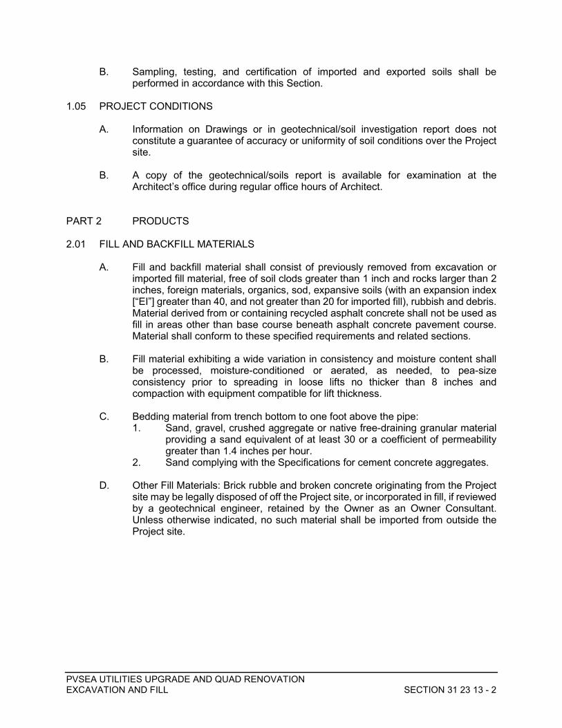
PVSEA UTILITIES UPGRADE AND QUAD RENOVATION EXCAVATION AND FILL SECTION 31 23 13 - 2
B. Sampling, testing, and certification of imported and exported soils shall be performed in accordance with this Section.
1.05 PROJECT CONDITIONS
A. Information on Drawings or in geotechnical/soil investigation report does not constitute a guarantee of accuracy or uniformity of soil conditions over the Project site.
B. A copy of the geotechnical/soils report is available for examination at the Architect’s office during regular office hours of Architect.
PART 2 PRODUCTS 2.01 FILL AND BACKFILL MATERIALS
A. Fill and backfill material shall consist of previously removed from excavation or
imported fill material, free of soil clods greater than 1 inch and rocks larger than 2 inches, foreign materials, organics, sod, expansive soils (with an expansion index [“EI”] greater than 40, and not greater than 20 for imported fill), rubbish and debris. Material derived from or containing recycled asphalt concrete shall not be used as fill in areas other than base course beneath asphalt concrete pavement course. Material shall conform to these specified requirements and related sections.
B. Fill material exhibiting a wide variation in consistency and moisture content shall be processed, moisture-conditioned or aerated, as needed, to pea-size consistency prior to spreading in loose lifts no thicker than 8 inches and compaction with equipment compatible for lift thickness.
C. Bedding material from trench bottom to one foot above the pipe: 1. Sand, gravel, crushed aggregate or native free-draining granular material
providing a sand equivalent of at least 30 or a coefficient of permeability greater than 1.4 inches per hour.
2. Sand complying with the Specifications for cement concrete aggregates.
D. Other Fill Materials: Brick rubble and broken concrete originating from the Project site may be legally disposed of off the Project site, or incorporated in fill, if reviewed by a geotechnical engineer, retained by the Owner as an Owner Consultant. Unless otherwise indicated, no such material shall be imported from outside the Project site.

PVSEA UTILITIES UPGRADE AND QUAD RENOVATION EXCAVATION AND FILL SECTION 31 23 13 - 3
E. Permeable Backfill: 1. Provide permeable backfill material within a 1 (horizontal): 1 (vertical)
envelope projected behind retaining structures consisting of gravel, crushed gravel, crushed rock, natural sands, manufactured sand, or combinations of these materials conforming to the following gradations: Sieve Size: Percentage Passing: 3/4 inch (19mm) 100 3/8 inch (10mm) 80 to 100 No. 100 0 to 8 No. 200 0 to 3
2. Those portions of fill material passing a No. 4 sieve shall provide a sand equivalent of at least 60.
3. Provided backing for weep-holes shall consist of two cubic feet of ¾-inch clean crushed gravel enveloped in Mirafi 140N filter fabric, or equivalent. Gravel shall conform to requirements for No. 3 concrete aggregate as specified in subsection 200-1.4 of the Standard Specifications for Public Works Construction.
4. Utility trench backfill placed within a 1H:1V envelope behind retaining walls shall consist of permeable backfill to within 18 inches of finish grade behind wall.
F. Cement-sand slurry shall be provided with one and one-half (1-½) sacks of cement per cubic yard of the mixture.
2.02 AGGREGATE BASE MATERIALS
Beneath Asphalt Concrete Pavement and Concrete Slabs on Grade: Provide "Crushed Aggregate Base" (“CAB”) or Processed Miscellaneous Base (“PMB”) as specified in Standard Specifications for Public Works Construction, Section 200 - Rock Materials, with 3/4 inch maximum size aggregates shall be used as base course beneath asphalt concrete. “Road Base” containing no recycled asphalt concrete available locally such as from Grimes Canyon shall be used beneath pedestrian –only on-grade concrete and pavers. Provide minimum 4-inch thick compacted base course, unless noted otherwise on plans.
PART 3 EXECUTION 3.01 GENERAL
A. Before excavation, contact Underground Service Alert of Southern California (“Dig
Alert”) for information on buried public utilities and pipelines. For onsite utilities, verify locations of buried utilities by potholing, as necessary.
B. Perform Work in such a manner, and at such times, as not to disrupt performance
of existing services to existing Project site facilities. Where an interruption is necessary, obtain review from District before proceeding.

PVSEA UTILITIES UPGRADE AND QUAD RENOVATION EXCAVATION AND FILL SECTION 31 23 13 - 4
3.02 PROTECTION A. Protect and guard excavations against danger to life, limb, and property as
required by, but not limited to, OSHA and CalOSHA regulations.
B. Protect existing improvements including foundations, on-grade improvements, and landscaping against damage. Contractor shall repair or replace damaged improvements.
C. Protect existing utility services and distribution systems from damage or displacement.
D. Remove or properly abandon with concrete plugs, conduits, or pipes not in service, exposed during Work. Remove concrete, clay, or other non-metallic pipe over 8 inches in diameter, unless otherwise indicated.
E. Shore, crib, or lag excavations and earthen banks as necessary to prevent cave in, erosion or gullying of sides.
F. Provide excavations free from standing water by pumping, draining, or providing protection against water intrusion. If soil becomes soft, soggy, or saturated, excavate to firm undisturbed earth and fill as required to achieve a stable bottom over which compaction of bedding or subgrade to minimum density requirements can be achieved. Slope adjacent grades away from excavations to minimize entry of water.
3.03 SHORING A. Provide shoring as necessary to properly and safely support earth slopes of
excavations, and existing curbs, sidewalks, gutter, drives, stairs, foundations, below- and on-grade structures against movement and collapse.
B. Design and Calculations: Provide in accordance with requirement of governing Cal-OSHA requirements.
C. Remove shoring upon completion of the Work of this section or when no longer needed unless required otherwise by authorities having jurisdiction. Compact loosened soils resulting from installation and removal of shoring.
3.04 EXCAVATION A. Unclassified Excavations: Comply with the Standard Specifications for Public
Works Construction, Section 300: "Earthwork", except as modified herein.
B. Prior to excavation, grass mat, organics, and debris shall be stripped from work areas, including stockpile areas, and disposed of offsite.
C. In asphalt concrete pavement areas: Remove concrete or bituminous pavement to straight lines by saw cutting incorporating a T-cut through asphalt concrete with a minimum width of 18 inches beyond excavation or trench wall.

PVSEA UTILITIES UPGRADE AND QUAD RENOVATION EXCAVATION AND FILL SECTION 31 23 13 - 5
D. Excavation bottoms shall be observed by the Geotechnical representative prior to placement of fill, including prior to filling in or smoothing over depressions or excavations from removal of below-grade structures or concrete, buried debris, utilities, or deleterious materials/tree stumps/root-balls.
E. Form sides of footings, pads, grade beams, and slab foundations, unless otherwise indicated. Provide excavations of sufficient size to permit installation and removal of forms and other required Work and compaction of voids adjacent thereto.
F. Machine-drill excavation for round shaft footings to size and depth indicated. Remove loose disturbed soil and cutting from shaft bottom. Upon completion using a clean-out bucket. Provide a collar or casing, or other adequate protection, to exclude dirt and debris and to prevent caving. Protect excavations with plank covers until concrete is placed.
G. Provide excavation bottoms level and free from loose disturbed material. Excavate to indicated or required elevations of undisturbed earth. Slope compacted subgrade beneath base course to drain.
H. Barricade trenches, ditches, pits, sumps, and similar Work, and in accord with Cal-OSHA standards and requirements.
I. Trenches over five feet in depth shall comply with the Construction Safety Orders of CalOSHA.
J. Where indicated or required to excavate in lawn areas, protect adjoining lawn areas outside of the Work area. Replace or install removed sod upon completion of backfill by installing sod level with adjacent lawns. If installation of removed sod fails, furnish sod, and install to match existing lawns.
K. For Structures: 1. Calculate excavation quantities based on elevations or depths indicated on
Drawings. 2. Provide 2,000 psi concrete for backfill of over-excavated areas to indicated
or required elevations. 3. Special preparation of bottom of excavated planes areas: Excavate areas
shown on Drawings as bottom of excavated planes (B.E.P.), by excavating and filling to indicated grades and elevations.
L. For Utilities: 1. Excavate trenches to required depth for utility lines, such as pipes,
conduits, and tanks, with minimum allowance of 4 inches at the bottom and 6 inches at the sides for bedding, pipe zone fill, or concrete encasement as indicated on Drawings, and as required to accommodate compacting equipment. Grade bottom of trenches to a uniform smooth surface.
a. Remove loose soil from the excavation bottom and maintain firm, unyielding bottom before placing sand bedding, or concrete encasement.
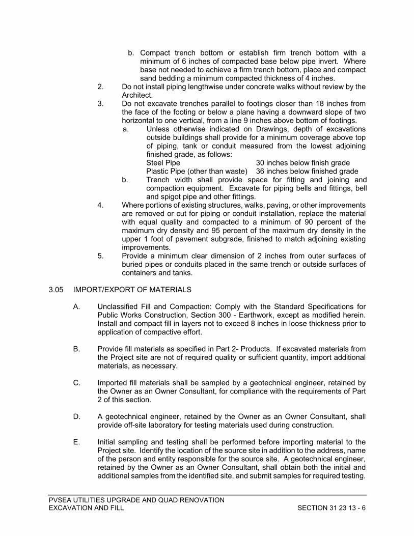
PVSEA UTILITIES UPGRADE AND QUAD RENOVATION EXCAVATION AND FILL SECTION 31 23 13 - 6
b. Compact trench bottom or establish firm trench bottom with a minimum of 6 inches of compacted base below pipe invert. Where base not needed to achieve a firm trench bottom, place and compact sand bedding a minimum compacted thickness of 4 inches.
2. Do not install piping lengthwise under concrete walks without review by the Architect.
3. Do not excavate trenches parallel to footings closer than 18 inches from the face of the footing or below a plane having a downward slope of two horizontal to one vertical, from a line 9 inches above bottom of footings. a. Unless otherwise indicated on Drawings, depth of excavations
outside buildings shall provide for a minimum coverage above top of piping, tank or conduit measured from the lowest adjoining finished grade, as follows: Steel Pipe 30 inches below finish grade Plastic Pipe (other than waste) 36 inches below finished grade
b. Trench width shall provide space for fitting and joining and compaction equipment. Excavate for piping bells and fittings, bell and spigot pipe and other fittings.
4. Where portions of existing structures, walks, paving, or other improvements are removed or cut for piping or conduit installation, replace the material with equal quality and compacted to a minimum of 90 percent of the maximum dry density and 95 percent of the maximum dry density in the upper 1 foot of pavement subgrade, finished to match adjoining existing improvements.
5. Provide a minimum clear dimension of 2 inches from outer surfaces of buried pipes or conduits placed in the same trench or outside surfaces of containers and tanks.
3.05 IMPORT/EXPORT OF MATERIALS
A. Unclassified Fill and Compaction: Comply with the Standard Specifications for Public Works Construction, Section 300 - Earthwork, except as modified herein. Install and compact fill in layers not to exceed 8 inches in loose thickness prior to application of compactive effort.
B. Provide fill materials as specified in Part 2- Products. If excavated materials from
the Project site are not of required quality or sufficient quantity, import additional materials, as necessary.
C. Imported fill materials shall be sampled by a geotechnical engineer, retained by
the Owner as an Owner Consultant, for compliance with the requirements of Part 2 of this section.
D. A geotechnical engineer, retained by the Owner as an Owner Consultant, shall provide off-site laboratory for testing materials used during construction.
E. Initial sampling and testing shall be performed before importing material to the Project site. Identify the location of the source site in addition to the address, name of the person and entity responsible for the source site. A geotechnical engineer, retained by the Owner as an Owner Consultant, shall obtain both the initial and additional samples from the identified site, and submit samples for required testing.

PVSEA UTILITIES UPGRADE AND QUAD RENOVATION EXCAVATION AND FILL SECTION 31 23 13 - 7
F. The geotechnical engineer, retained by the Owner as an Owner Consultant, shall perform additional sampling during import operations. If the total quantity of import is determined to be greater than 1000 cubic yards of material, one sample shall be obtained and submitted for testing for each 250 cubic yards of imported material. If the total quantity of import is determined to be less than 1000 yards, one sample shall be obtained and submitted for testing for each 100 cubic yards of imported material.
G. The testing laboratory shall perform the required tests and report results of tests noting if the tested material passed or failed such tests and shall furnish copies to the Owner and others as required. Report shall state tests were conducted under the responsible charge of a licensed State of California professional engineer and the material was tested in accordance with applicable provisions of the Contract Documents.
H. Bills of lading or equivalent documentation will be submitted to the Project Inspector on a daily basis.
3.06 SUBGRADE PREPARATION AND INSTALLATION OF MATERIALS A. The upper 1 foot of subgrade in areas to receive pavers, buried structures or
footings for short landscape walls shall be compacted to a minimum of 90 percent of the maximum dry density determined by ASTM D1557, latest edition. The upper foot of subgrade in areas to receive on-grade concrete or asphalt concrete pavement shall be compacted to a minimum of 95 percent of the maximum dry density. No fill shall be placed prior to observation of excavation bottom by the Geotechnical representative.
B. Fill or backfill materials shall be installed in horizontal layers placed in loose
thickness not exceeding 8 inches and of appropriate thickness for the type of compaction equipment being used, unless otherwise required. Each layer shall consist of previously- processed and moisture-conditioned or aerated fill material prior to placement. Unless otherwise reviewed by the geotechnical engineer, retained by the Owner as an Owner Consultant, each layer of fill material shall cover the length and width of the area to be filled before the next layer of material is installed. Top surface of each layer shall be installed to an approximate level with a crown or crossfall of at least 1 in 50, but not more than 1 in 20. Provide adequate drainage at all times during installation of the Work of this section.
C. Structures:
1. After concrete has been placed, forms removed, and concrete Work inspected, backfill excavations and voids resulting from removal of forms in loose lifts not exceeding 8 inches in thickness and appropriate for equipment used for compaction. Place backfill and compact in successive lifts to indicated or required grades. Backfill simultaneously on each side of walls or grade beams. Remove rubbish, debris, and other waste materials from excavations before placing backfill.
2. Before placing backfill, adequately cure concrete and provide bracing, if required to stabilize structure. Protect waterproofing or damp-proofing against damage during backfilling operations, with required protection board. Remove bracing as backfill operation progresses.

PVSEA UTILITIES UPGRADE AND QUAD RENOVATION EXCAVATION AND FILL SECTION 31 23 13 - 8
3. Do not furnish or install expansive soils for retaining wall backfill. No fill shall be placed with an Expansive Index greater than 40.
4. Rigidly control the amount of water to be installed to provide optimum moisture content for type of fill material furnished. Do not over-saturate or compact by flooding or jetting.
5. Install wall backfill before installing railings and fences on walls. 6. Install weep hole drainage at the backside of walls so the backing
completely covers the weep holes, is horizontally centered and extends at least 12 inches above the bottom of the weep opening. Envelope drainage material with filter fabric.
7. Where a reviewed drainage matting system is provided instead of permeable backfill for retaining structures, install in accordance with the manufacturer recommendations.
D. Utilities: 1. Do not install backfill until the Work of this section has been inspected and
tested. Do not furnish or install materials excavated from the Project site containing materials not permitted for backfill.
2. Backfill excavated utility trenches or other excavations located outside of barricaded installation areas the same day, so excavations are not left open overnight.
3. Install backfill in layers not exceeding 8 inches in loose thickness and appropriate for the compacting equipment used, except cement-sand slurry.
4. If materials excavated from the Project site are not permitted for trench backfill in paved areas, backfill trenches with a cement-sand slurry mix. Install backfill to an elevation of the existing undisturbed grades plus one inch.
3.07 COMPACTING
A. Each layer of fill material shall be compacted by tamping, kneading, sheepsfoot rollers, or pneumatic-tired rollers to provide specified relative compaction. At inaccessible locations, provide specified compaction by manually-held, operated, and directed compaction equipment.
B. Install and compact sand bedding to a minimum compacted thickness of 4 inches,
or as shown on drawings, to provide a uniform bearing under the full length of piping and conduits.
C. Unless otherwise indicated, compact each layer of fill material to a relative compaction of at least 90 percent of the maximum dry density and a minimum of 95 percent in the upper 1 foot of on-grade concrete, pavement subgrade, and aggregate base course beneath paving, pavers, or on-grade concrete.
D. When fill materials, or a combination of fill materials, are encountered or provided which develop densely packed surfaces as a result of installation or compacting operations, scarify each layer of compacted fill before installing the next succeeding layer.
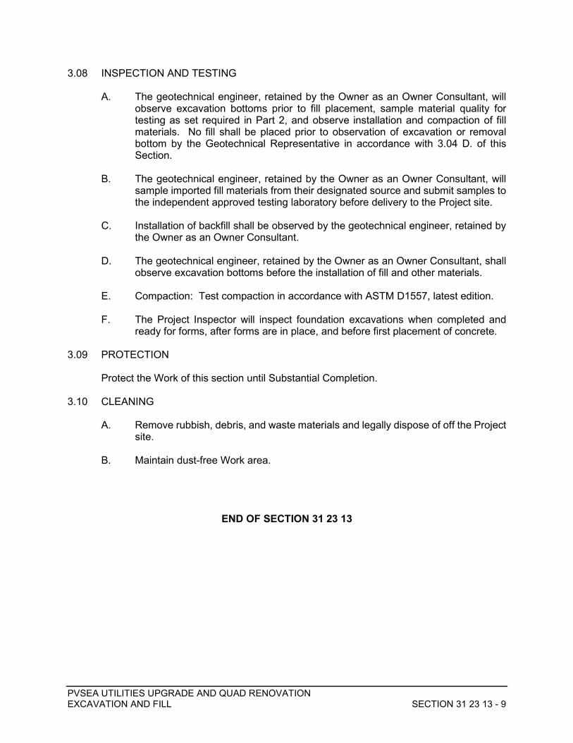
PVSEA UTILITIES UPGRADE AND QUAD RENOVATION EXCAVATION AND FILL SECTION 31 23 13 - 9
3.08 INSPECTION AND TESTING
A. The geotechnical engineer, retained by the Owner as an Owner Consultant, will observe excavation bottoms prior to fill placement, sample material quality for testing as set required in Part 2, and observe installation and compaction of fill materials. No fill shall be placed prior to observation of excavation or removal bottom by the Geotechnical Representative in accordance with 3.04 D. of this Section.
B. The geotechnical engineer, retained by the Owner as an Owner Consultant, will sample imported fill materials from their designated source and submit samples to the independent approved testing laboratory before delivery to the Project site.
C. Installation of backfill shall be observed by the geotechnical engineer, retained by the Owner as an Owner Consultant.
D. The geotechnical engineer, retained by the Owner as an Owner Consultant, shall observe excavation bottoms before the installation of fill and other materials.
E. Compaction: Test compaction in accordance with ASTM D1557, latest edition.
F. The Project Inspector will inspect foundation excavations when completed and ready for forms, after forms are in place, and before first placement of concrete.
3.09 PROTECTION Protect the Work of this section until Substantial Completion.
3.10 CLEANING
A. Remove rubbish, debris, and waste materials and legally dispose of off the Project site.
B. Maintain dust-free Work area.
END OF SECTION 31 23 13

PVSEA UTILITIES UPGRADE AND QUAD RENOVATION CONSTRUCTION STORMWATER POLLUTION PREVENTION SECTION 31 25 00 - 1
SECTION 31 25 00 CONSTRUCTION STORMWATER POLLUTION PREVENTION
PART 1 GENERAL 1.01 DESCRIPTION
Provide materials, equipment and transportation and perform labor as required for installing, maintaining, repairing and, upon completion of construction, removing temporary storm water pollution prevention devices and collected pollutant material.
1.02 RELATED DOCUMENTS
Drawings and general provisions of the Contract, including General and Supplementary Conditions and other Division 1 Specification Sections, apply to this Section.
1.03 RELATED WORK SPECIFIED ELSEWHERE
Section 31 10 00 – Site Clearing Section 31 23 00 – Trenching and Backfilling Section 32 12 16 – Asphalt Concrete Paving
1.04 STANDARD SPECIFICATIONS
A. Construction materials and methods shall be in accordance with the Standard Specifications for Public Works Construction, 2015 edition (SSPWC), published by Building News, Inc., except as modified or otherwise specified herein (hereinafter the Standard Specifications).
B. In case of conflict between the Standard Specifications and the Project
Specifications, the Project Specifications shall govern. 1.05 REFERENCE SPECIFICATIONS
A. Where called for on the Drawings or in these Specifications, construction materials and methods shall be in accordance with Construction BMP Online Handbook, January 2015 edition, available online from the California Stormwater Quality Association.
B. In case of conflict between the Standard Specifications and a reference
specification, the reference specification shall govern. C. In case of conflict between a reference specification and these Project
Specifications, the more stringent provision shall govern, as determined by the Owner’s Representative and the Engineer.
1.06 REGULATORY REQUIREMENTS
A. Construction shall comply with the California Code of Regulations, Title 24.
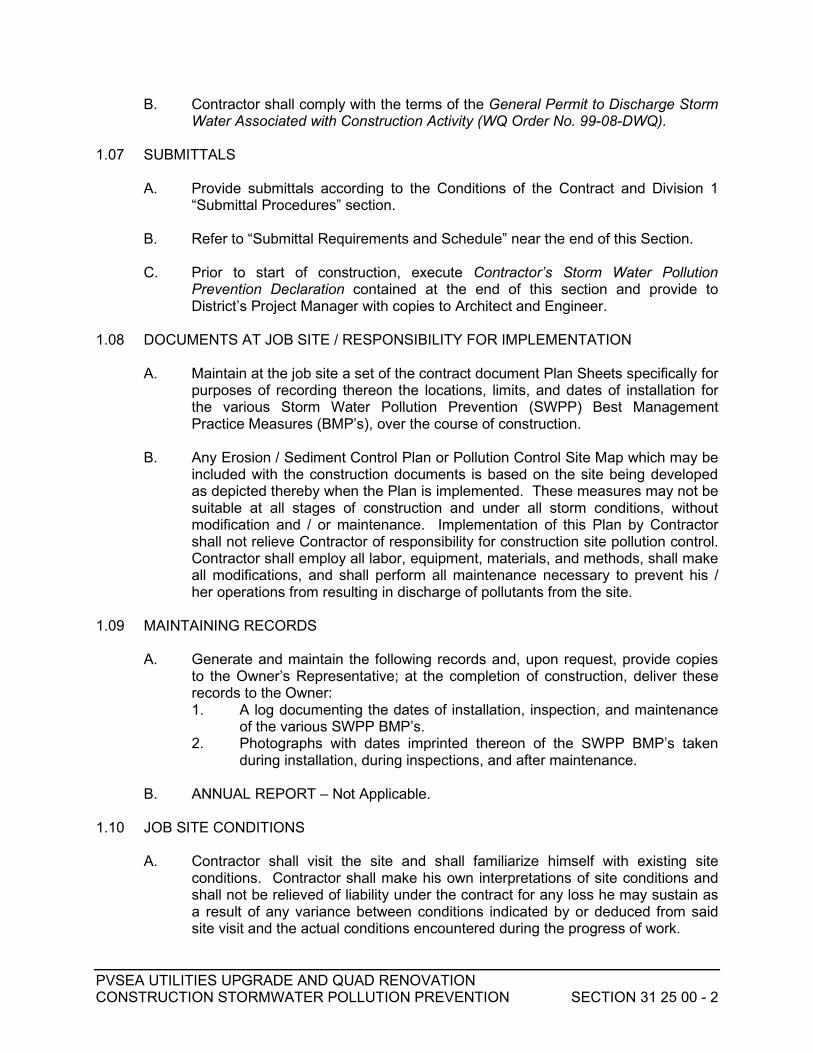
PVSEA UTILITIES UPGRADE AND QUAD RENOVATION CONSTRUCTION STORMWATER POLLUTION PREVENTION SECTION 31 25 00 - 2
B. Contractor shall comply with the terms of the General Permit to Discharge Storm Water Associated with Construction Activity (WQ Order No. 99-08-DWQ).
1.07 SUBMITTALS A. Provide submittals according to the Conditions of the Contract and Division 1
“Submittal Procedures” section. B. Refer to “Submittal Requirements and Schedule” near the end of this Section.
C. Prior to start of construction, execute Contractor’s Storm Water Pollution Prevention Declaration contained at the end of this section and provide to District’s Project Manager with copies to Architect and Engineer.
1.08 DOCUMENTS AT JOB SITE / RESPONSIBILITY FOR IMPLEMENTATION
A. Maintain at the job site a set of the contract document Plan Sheets specifically for
purposes of recording thereon the locations, limits, and dates of installation for the various Storm Water Pollution Prevention (SWPP) Best Management Practice Measures (BMP’s), over the course of construction.
B. Any Erosion / Sediment Control Plan or Pollution Control Site Map which may be
included with the construction documents is based on the site being developed as depicted thereby when the Plan is implemented. These measures may not be suitable at all stages of construction and under all storm conditions, without modification and / or maintenance. Implementation of this Plan by Contractor shall not relieve Contractor of responsibility for construction site pollution control. Contractor shall employ all labor, equipment, materials, and methods, shall make all modifications, and shall perform all maintenance necessary to prevent his / her operations from resulting in discharge of pollutants from the site.
1.09 MAINTAINING RECORDS
A. Generate and maintain the following records and, upon request, provide copies to the Owner’s Representative; at the completion of construction, deliver these records to the Owner: 1. A log documenting the dates of installation, inspection, and maintenance
of the various SWPP BMP’s. 2. Photographs with dates imprinted thereon of the SWPP BMP’s taken
during installation, during inspections, and after maintenance.
B. ANNUAL REPORT – Not Applicable. 1.10 JOB SITE CONDITIONS
A. Contractor shall visit the site and shall familiarize himself with existing site conditions. Contractor shall make his own interpretations of site conditions and shall not be relieved of liability under the contract for any loss he may sustain as a result of any variance between conditions indicated by or deduced from said site visit and the actual conditions encountered during the progress of work.

PVSEA UTILITIES UPGRADE AND QUAD RENOVATION CONSTRUCTION STORMWATER POLLUTION PREVENTION SECTION 31 25 00 - 3
B. Contractor shall assume sole and complete responsibility for job site conditions during the course of construction of this project including safety of all persons and property; this requirement shall apply continuously and not be limited to normal working hours.
C. Contractor shall assume sole and complete responsibility for protection of public
and private property in the vicinity of the job site and shall, at Contractor's expense, repair or replace to original condition all existing improvements within or in the vicinity of the job site which are not designated for removal and which are damaged or removed as a result of Contractor's operations.
D. Contractor shall defend, indemnify, and hold design professionals harmless from
all liability and claims, real or alleged, in connection with the performance of work on this project, excepting liability arising from the sole negligence of design professionals.
E. Existing buried pipelines and conduits known to the preparer of the Drawings are
shown on the Drawings. However, all such pipelines, conduits and structures may not be shown and the locations of those shown are approximate only and have not been independently verified by the preparer of the Drawings. 1. Contractor shall independently verify or determine the presence of
existing buried pipelines, conduits, and structures within the work area with the utility companies, the water and sanitary agencies, and the Owner. Before commencing work, Contractor shall determine the exact locations including depths of all existing underground pipelines, conduits, and structures, including service connections, which may affect or be affected by his operations and shall mark these locations with paint or flags.
2. Contractor shall be fully responsible for any and all damages which might be occasioned by Contractor's failure to exactly locate and preserve any and all underground pipelines, conduits, and structures.
3. Upon becoming aware of existing buried pipelines, conduits or structures not shown or located differently than shown on the Drawings, Contractor shall immediately notify the Owner's Representative and the owner of the pipeline, conduit, or structure by telephone and in writing. If such pipeline, conduit, or structure affects or is affected by the work, Contractor shall obtain written permission and direction from the District and the owner of the pipeline, conduit, or structure before proceeding with the work, excepting that in an emergency affecting safety of life, work or adjacent property, Contractor shall act at once without instructions to prevent injury or loss.
1.11 STORM WATER POLLUTION PREVENTION PLAN IMPLEMENTATION
A. Prior to start of construction, Contractor shall implement BMP’s to address the following non-storm water issues which are related to Storm Water Pollution Prevention (SWPP). Contractor shall then maintain, monitor, and modify as necessary these same BMP measures throughout construction: 1. Material tracking off-site.
PVSEA UTILITIES UPGRADE AND QUAD RENOVATION CONSTRUCTION STORMWATER POLLUTION PREVENTION SECTION 31 25 00 - 4
2. Equipment wash off, refueling and maintenance (if applicable). 3. Hazardous material storage (if applicable). 4. Concrete, paint, and plaster wash off / cleanup (if applicable). 5. Dewatering operations (if applicable). 6. Spill prevention and control. 7. Solid waste management. 8. Hazardous waste management. 9. Contaminated soil management. 10. Sanitary / septic waste management. 11. Liquid waste management. 12. Water conservation practices. 13. Illicit connection / discharge. 14. Potable water and irrigation water runoff / release. 15. Material delivery, storage, and use. B. Once ground disturbance has begun, Contractor shall implement, maintain, and
monitor BMP measures to address storm water related concerns for SWPP, including: 1. Wind erosion (dust) control. 2. Street sweeping and vacuuming. 3. Paving and grinding operations. 4. Concrete finishing (if applicable). 5. Silt fence and gravel bag berms when forecast of rain probability is 40%
or greater. 6. Straw bale and sandbag barrier when forecast of rain probability is 40%
or greater. 7. Storm drain inlet protection when forecast of rain probability is 40% or
greater. 8. Fiber roll berm when forecast of rain probability is 40% or greater. 9. Temporary stream crossings or clear water diversions if water is flowing
in the stream or when forecast of rain probability is 40% or greater. 10. Stockpile management when forecast of rain probability is 40% or
greater.
C. Contractor shall implement, maintain, and monitor other Best Management Practice measures (BMP’s), as needed, on a case by case basis.
D. Contractor shall adapt the BMP measures throughout the construction period as
necessary to address changing site conditions, construction materials, and construction methods to prevent the discharge of pollutants from the project site.
E. Contractor shall immediately address any deficiencies in implementation or
adequacy of the BMP’s identified by the Inspector or governing authority. 1.12 FINES
A. Failure of the Contractor to properly implement Best Management Practice measures for Storm Water Pollution Prevention, may result in fines being levied against the Santa Barbara School District (SBSD) by the State Regional Water Quality Control Board (SRWQCB) or other governing authority.

PVSEA UTILITIES UPGRADE AND QUAD RENOVATION CONSTRUCTION STORMWATER POLLUTION PREVENTION SECTION 31 25 00 - 5
B. Contractor shall make full restitution to the SBSD for any and all fines levied against SBSD by the SRWQCB or other local, State or Federal agencies as a result of the Contractor’s failure to maintain records or to implement, maintain and monitor BMP’s.
PART 2 PRODUCTS 2.01 STABILIZED CONSTRUCTION ENTRANCE
A. STEEL PLATE / ROCK ENTRANCE 1. Material for roadbed shall be crushed rock, varying between 3 inches and
6 inches in largest dimension. 2. Geotextile fabric for placement between crushed rock and soil subgrade
shall be Mirafi 140N non-woven polypropylene, or equivalent approved by the Engineer, suitable for soil separation and filtration.
3. Steel plates for rumble strip shall be 8’-minimum wide by 8’-minimum long plates suitable, unsupported, for H-20 traffic loading. Plates shall be supplied with continuous transverse steel ribs at 4”-maximum spacing; ribs shall be either ½ inch minimum thick by 2 inch minimum high bars or equal-leg 3 inch by 3 inch by ½” minimum thick angles, welded to plate.
B. CRUSHED ROCK ENTRANCE
1. Material for roadbed shall be crushed rock, varying between 3 inches and 6 inches in largest dimension.
2. Geotextile fabric for placement between crushed rock and soil subgrade shall be Mirafi 140N non-woven polypropylene, or equivalent approved by the Engineer, suitable for soil separation and filtration.
C. STEEL PLATE ENTRANCE
1. Steel plate entrance is for use on existing concrete or asphalt concrete paved areas only.
2. Steel plates for rumble strip shall be 8’-minimum wide by 8’-minimum long plates suitable, unsupported, for H-20 traffic loading. Plates shall be supplied with continuous transverse steel ribs at 4”-maximum spacing; cribs shall be either ½ inch minimum thick by 2 inch minimum high bars or equal-leg 3 inch by 3 inch by ½” minimum thick angles, welded to plate.
2.02 SILT FENCE
A. Silt fence fabric shall be a pervious sheet of synthetic polymer composed of at least 85% by weight ethylene, propylene, amide, ester, or vinylidene yarn, woven or non-woven; it shall contain stabilizers and/or inhibitors to resist deterioration by heat, water, and ultra-violet light. The fabric shall conform to the following criteria:
1. The equivalent opening size (U.S. standard sieve) shall be no larger than 70; where discharge would be to stream, lake, or wetland, E.O.S. shall be no larger than 100.

PVSEA UTILITIES UPGRADE AND QUAD RENOVATION CONSTRUCTION STORMWATER POLLUTION PREVENTION SECTION 31 25 00 - 6
2. The required fabric tensile strength (per A.S.T.M. D-4632) shall be 120 pounds minimum with posts installed at 4-foot spacing.
B. Posts for supporting fence fabric shall be 3 x 3 wood or 1.33 pounds per linear
foot steel with a minimum length of 42 inches. Steel posts shall have projections for attaching wire.
2.03 STRAW BALE DIKE / WEIR
A. Straw bales shall be standard size, bound with wire or nylon. B. The straw bales shall be placed tightly against the ground or pavement surface
and one another and shall be hand tamped firmly into place. 2.04 SILT TRAP AT DRAIN INLET
A. Silt trap fabric shall be a pervious sheet of synthetic polymer composed of at least 85% by weight ethylene, propylene, amide, ester, or vinylidene yarn, woven or non-woven; it shall contain stabilizers and / or inhibitors to resist deterioration by heat, water, and ultraviolet light. The fabric shall conform to the following criteria: 1. The equivalent opening size (U.S. Standard sieve) shall be no larger than
70; where discharge would be to stream, lake, or wetland, E.O.S. shall be no larger than 100.
2. The required fabric tensile strength (per A.S.T.M. D-4632) shall be 120 pounds minimum.
B. Where called for on the drawings, common clay bricks or solid masonry blocks
shall be used to hold the fabric in place.
2.05 SANDBAG BARRIER
A. Sandbag shall be woven polypropylene, polyethylene or polyamide fabric having minimum unit weight of 4 ounces per square yard and mullen burst strength exceeding 300 pounds per square inch, in conformance with the requirements of ASTM Designation D3786, and having ultraviolet stability exceeding 70%, in conformance with the requirements of ASTM Designation D4355.
B. Each sand-filled bag should have a length of 18 inches, width of 12 inches,
thickness of 3 inches, and mass of approximately 33 pounds. Bag dimensions are nominal.
C. All sandbag fill material shall consist of natural or manufactured granular
material, or a combination thereof.
PVSEA UTILITIES UPGRADE AND QUAD RENOVATION CONSTRUCTION STORMWATER POLLUTION PREVENTION SECTION 31 25 00 - 7
2.06 GRAVEL BAG FILTER A. Gravel bags shall be woven polypropylene, polyethylene or polyamide fabric
having minimum until weight of 4 ounces per square yard and mullen burst strength exceeding 300 pounds per square inch, in conformance with the requirements of ASTM designation D3786, and having stability exceeding 70%, in conformance with the requirements of ASTM designation D4355.
B. Each gravel-filled bag should have a length of 18 inches, width of 12 inches,
thickness of 3 inches and mass of approximately 33 pounds. Bag dimensions are nominal.
C. Gravel bag filled material should be 0.5 to 1 inch, clean crushed rock, free from
clay, organic matter, and other deleterious materials. PART 3 EXECUTION 3.01 GENERAL REQUIREMENTS
A. Contractor shall implement NPDES Permit Requirements including: 1. Reviewing the Storm Water Pollution Prevention Plan (SWPPP).
2. Amending the SWPPP to address changes in site conditions, construction materials, or construction operations that may affect the discharge of pollutants from the site.
3. Holding a mandatory training seminar with the general contractor’s personnel, subcontractors’ personnel, and material suppliers’ personnel to explain the job requirements related to Storm Water Pollution Prevention; requiring those that attend to sign a training log indicating that they have attended the seminar and that they agree to implement and maintain the BMP’s throughout construction.
4. Conducting weekly inspection and maintenance of the in-place BMP’s. 5. Conducting inspections of the BMP’s before each anticipated storm event
and after each actual storm event; making the necessary repairs or modifications at the time of the inspection.
6. Ensuring full compliance with the Permit and implementing all elements of the Storm Water Pollution Prevention Plan, including elimination of all unauthorized discharges and preparation of an annual compliance evaluation.
B. The location and extent of the various BMP’s shall be reviewed at the site by the
DSA inspector at the beginning of the installation process. Provide 24 hours minimum notice.
C. The locations of the various BMP’s may require adjustment due to changing site conditions and additional installations may be required by the inspector.
D. All BMP’s shall be inspected and repaired at the end of each work week and, in addition, before and after each storm.

PVSEA UTILITIES UPGRADE AND QUAD RENOVATION CONSTRUCTION STORMWATER POLLUTION PREVENTION SECTION 31 25 00 - 8
E. Pollutant deposits shall be removed from BMP’s after each storm to restore their capacity. Soil material shall be stockpiled such that it cannot again result in sediment transport on- or off-site; other pollutants collected shall be remove from the site and disposed of in a proper and legal manner.
F. During the rainy season, the site shall be maintained such that no sediment or other pollutant-laden runoff enters the storm drainage system or flows offsite.
G. A standby crew shall be provided by the contractor for emergency work during rainstorms and shall remain onsite as needed to maintain BMP’s during periods of precipitation.
3.02 STABILIZED CONSTRUCTION ENTRANCE
A. STEEL PLATE / ROCK ENTRANCE 1. Clear the existing ground surface of vegetation and debris and grade the
roadbed and immediately downstream of the roadbed to provide positive and controlled drainage in accordance with the plan detail.
2. Place crushed rock over filter fabric. 3. Place steel plates.
B. CRUSHED ROCK ENTRANCE 1. Clear the existing ground surface of vegetation and debris and grade the
roadbed and immediately downstream of the roadbed to provide positive and controlled drainage in accordance with the plan detail.
2. Place crushed rock over filter fabric. C. STEEL PLATE ENTRANCE
1. Sweep clean the existing pavement surface beneath, to either side and immediately upstream and downstream prior to placing steel plates.
2. Place steel plates on top of the existing pavement, paying attention to prevent damage to the existing pavement and where applicable near by existing curbs, walls, etc.
3. Construct cold-mix A.C. conform patches to hold plates in place. D. MAINTENANCE
1. Require that all employees, subcontractors, and suppliers utilize the stabilized construction entrance.
2. Inspect routinely to verify that steel plates have not moved out of place and that plate or crushed rock is not encroaching into sidewalk or other public right-of-way.
3. Remove soil collected between plate ribs and rock voids as necessary to prevent clogging, at least once a week, and prior to any storm event.
4. For Crushed Rock Entrance: remove, clean, and replace rock or reconstruct as necessary to maintain effectiveness of entrance for removing soil from vehicles.
5. Inspect stabilized construction entrance daily and sweep tracked sediment as needed.

PVSEA UTILITIES UPGRADE AND QUAD RENOVATION CONSTRUCTION STORMWATER POLLUTION PREVENTION SECTION 31 25 00 - 9
3.03 EROSION AND SEDIMENT CONTROL
A. GENERAL 1. Any Erosion / Sediment Control Plan which may be included with the
construction documents is based on the site being developed as depicted thereby when the Plan is implemented. These measures may not be suitable at all stages of construction and under all storm conditions, without modification and / or maintenance. Implementation of this Plan by Contractor shall not relieve Contractor of responsibility for construction site erosion control measures. Contractor shall employ all labor, equipment, materials, and methods necessary to prevent his / her operations from resulting in discharge from the site of silt (mud) and / or debris.
2. Erosion / sediment control measures shall be in place at anytime during the year when the forecast of rain probability is 40% or greater, for each year, until the site improvements, including grading, paving, drainage devices, and landscaping, have been constructed. Erosion / sediment control measures shall be inspected and repaired as necessary each week and before and after each storm.
3. The location and extent of erosion control measures shall be reviewed at the site by the inspector at the beginning of the installation process. Provide 24 hours minimum notice.
4. The locations of swales, erosion / sediment control berms, barriers, and silt fences may require adjustment due to changing site conditions and additional installations may be required by the inspector.
5. During the rainy season, all erosion / sediment control measures shall be inspected and repaired each week and before and after each storm.
6. Soil and debris deposits shall be removed from erosion control swales and from behind erosion / sediment control berms, barriers, and silt fences after each storm to restore their capacity. The spoil material shall be stockpiled such that it cannot again result in sediment transport on or off-site.
7. During the rainy season, all paved areas shall be kept clear of soil material and debris. The site shall be maintained such that no sediment-laden runoff enters the storm drainage system or sheet-flows offsite.
8. A standby crew shall be provided by the contractor for emergency work during rainstorms and shall remain onsite as needed to maintain BMP’s during periods of precipitation.
B. SILT FENCE
1. The height of silt fence shall not exceed 24 inches above grade. On slopes, the fence line shall follow an elevation contour as closely as possible. Where crossing small swales, the fence line shall be curved upstream on each side to direct the flow towards the middle of the fence arc.
2. If possible, the filter fabric shall be cut from a continuous roll to avoid the use of joints. When joints are necessary, filter cloth shall be spliced only at a support post, with a minimum 6-inch overlap, with both ends securely fastened to the post.

PVSEA UTILITIES UPGRADE AND QUAD RENOVATION CONSTRUCTION STORMWATER POLLUTION PREVENTION SECTION 31 25 00 - 10
3. Posts shall be spaced a maximum of 4 feet apart and be driven securely into the ground to a minimum depth of 12 inches. Subject to inspector’s acceptance, chain link construction or permanent fencing may be used to support fabric in lieu of silt fence posts.
4. A trench shall be excavated approximately 6 inches in width and 6 inches in depth along the line of posts on the upslope side of the barrier.
5. Filter fabric shall be stapled or wired to the fence, and 12 inches of the fabric shall extend into the trench. The fabric shall not extend more than 24 inches above the original ground surface. Filter fabric shall not be stapled to existing trees.
6. The location of silt fencing may require adjustment due to changing site conditions and additional installations may be required by the DSA inspector.
C. STRAW BALE DIKE / WEIR
1. Bales shall be placed in a row or as shown on the plan with ends tightly abutting.
2. Each bale shall be embedded in the soil a minimum of 4 inches. 3. Bales shall be securely anchored in place by two stakes driven through
the bales. The first stake in each bale shall be driven toward the previously laid bale to force bales together.
4. The locations of straw bale dikes / weirs may require adjustments due to changing site conditions and additional installations may be required by the DSA inspector.
D. SILT TRAP AT DRAIN INLET
1. For larger inlets having steel or cast iron grates, the fabric shall be installed between the frame and grate and then the grate reseated to secure the fabric in place. The fabric panel used to cover the inlet shall be a minimum of 12” larger in square dimension or in diameter than the grate.
2. For smaller inlets, the fabric shall be centered over the in-place grate and held down with bricks or solid masonry blocks. The fabric panel size used to cover the inlet shall be a minimum of 24” square or in diameter.
3. The filter fabric shall be cut from a continuous roll, as no joints will be allowed.
E. SANDBAG BARRIER 1. The height of the sandbag barrier shall be approximately 6”, or two bags. 2. The sandbags shall be placed tightly against the ground or pavement
surface and one another and shall be hand tamped into place. F. GRAVEL BAG FILTER 1. The height of the gravel bag filter shall be approximately 3”, or one bag. 2. The gravel bags shall be placed tightly against the ground or pavement
surface and one another and shall be hand tamped into place.

PVSEA UTILITIES UPGRADE AND QUAD RENOVATION CONSTRUCTION STORMWATER POLLUTION PREVENTION SECTION 31 25 00 - 11
G. MAINTENANCE 1. SILT FENCE
a. Silt fences shall be inspected each week, before a storm, periodically during rainfall, and after each storm. Any required repairs shall be made immediately.
b. Should the fabric on a silt fence decompose or become ineffective during the time the fence or barrier is still necessary, the fabric shall be replaced immediately.
c. Sediment deposits (spoils) shall be removed when depth of deposits reach approximately one-half the height of the silt fence (12-inches maximum) and after each storm. Sediment buildups must be removed when bulges develop in the fence regardless of depth of deposition.
2. STRAW BALE DIKES / WEIRS a. Straw bale dikes / weirs shall be inspected each week, before a
storm, periodically during rainfall, and after each storm. Any required repairs shall be made immediately.
b. Should the straw bales decompose or become ineffective during the time the devices are still necessary, they shall be replaced immediately.
c. Sediment deposits shall be removed when deposits reach approximately one-half the height of the dike / weir.
3. SILT TRAPS AT DRAIN INLET a. Silt traps shall be inspected each week, before a storm,
periodically during rainfall, and after each storm. Any required maintenance or repair shall be made immediately.
b. Sediment deposits (spoil) and other debris trapped on the fabric shall be removed as necessary during rainfall to maintain inflow to the drain inlet.
c. Should the silt trap fabric decompose or become ineffective during the time the devices are still necessary, it shall be replaced immediately.
4. SANDBAG BARRIER a. Sandbag barrier shall be inspected each week, before a storm,
periodically during rainfall, and after each storm. Any required repairs shall be made immediately.
b. Should the fabric of the sandbag decompose during the time the barrier is still necessary, the sandbag shall be removed and replaced immediately. Sandbags exposed to sunlight will need to be replaced every two to three months.
c. Washouts or other damage shall be repaired immediately. d. Sediment and debris that accumulate behind the sandbag barrier
must be periodically removed in order to maintain the barrier effectiveness. Materials should be removed when the accumulation reaches one third of the barrier height.
5. GRAVEL BAG FILTERS a. Gravel bag filters shall be inspected each week, before storm,
periodically during rainfall, and after each storm. Any required repairs shall be made immediately.

PVSEA UTILITIES UPGRADE AND QUAD RENOVATION CONSTRUCTION STORMWATER POLLUTION PREVENTION SECTION 31 25 00 - 12
b. Should the fabric of the gravel bag decompose during the time the filter is still necessary, the gravel bag shall be removed and replaced immediately. Gravel bags exposed to sunlight will need to be replaced every two to three months.
c. Washouts or other damage shall be repaired immediately. d. Sediment and debris that accumulates behind the gravel bag filter
must be periodically removed in order to maintain the filter effectiveness. Material should be removed when the accumulation reaches one third of the filter height.
6. Spoil material shall be disposed of off-site at an appropriate disposal facility. During construction, the soil material may be temporarily stockpiled on-site in such a manner that it cannot again result in sediment transportation on or off-site.
3.04 POLLUTION CONTAINMENT AREA
A. EARTH BERM 1. Develop containment area by constructing earth berms in accordance
with the plan detail. Onsite soil free of organic material and rocks larger than 1” in diameter may be used for the earth berms.
2. Grade the area outside of the earth berms to direct storm runoff away from the containment area.
B. STRAW BERM
1. Sweep clean the existing pavement surface within the containment area, to either side and immediately upstream and downstream prior to constructing the containment berms.
2. Develop containment area by constructing straw bale and sandbag berms in accordance with the plan detail.
C. MAINTENANCE
1. Routinely inspect the containment structure (berm) to ensure that it is intact and provides the required freeboard. Provide additional materials and reform or replace the berm as necessary to maintain its integrity.
2. Regularly remove and properly dispose of offsite all pollutants deposited within the containment area, in accordance with all applicable local, state, and federal laws.
3.05 DISPOSAL
A. Remove from the work area, transport to a suitable off-site location, and legally dispose of all unsuitable soil materials, rubbish, debris, and other pollutants resulting from construction operations.
B. Burning is not permitted within the work area.

PVSEA UTILITIES UPGRADE AND QUAD RENOVATION CONSTRUCTION STORMWATER POLLUTION PREVENTION SECTION 31 25 00 - 13
3.06 PROJECT COMPLETION
A. Upon completion of the project, including landscaping and site cleanup, and in a timely manner: 1. Submit to the District the Records listed in Subsection 1.09.
3.07 SUBMITTAL REQUIREMENTS AND SCHEDULE
A. Include this form with submittals of these Specification section.
Contractor's [Contractor is to acknowledge with initials each submittal included] Initials: ____ ____ Letter of explanation attached for each submittal not included. ____ All submitted products are as specified.
B. SUBMITTAL SCHEDULE
____ 1. Submit manufacturer's product data indicating tensile strength and E.O.S. for silt fence / silt trap fabric.
____ 2. Submit material type and dimensions for silt fence posts. ____ 3. Submit manufacturer's product data indicating burst strength,
ultraviolet stability and permeability for sandbags and gravel bags. ____ 4. Submit sieve analysis for gravel bag fill material.
3.08 CONTRACTOR’S STORM WATER POLLUTION PREVENTION DECLARATION
A. As Contractor for this project, we hereby declare as follows: 1. We understand it is our responsibility to construct and maintain pollution
prevention measures, including those for erosion and sediment control, as necessary to prevent any pollutant at any level from being conveyed off the construction site and that these measures must continue to be maintained until the required post-construction pollution prevention measures are in place and completely functional, including permanent landscaping.
2. We understand that site development and storm characteristics will evolve over the course of construction and that it is our responsibility to not only implement storm water pollution prevention measures, but to make adjustments and expansion in the implementation as necessary to adapt to our construction operations and schedule and to address evolving site conditions and actual weather conditions.
3. We understand it is our responsibility to train employees and subcontractors regarding these requirements and to maintain records of the installation, modification, inspection, and maintenance of storm water pollution prevention measures including, but not limited to: training, inspection, maintenance logs; record drawings showing locations, limits, and dates of installation for various measures; dated photographs and field sketches.

PVSEA UTILITIES UPGRADE AND QUAD RENOVATION CONSTRUCTION STORMWATER POLLUTION PREVENTION SECTION 31 25 00 - 14
4. We are familiar with and agree to implement best management practice storm water pollution prevention measures including installation, routine inspection and maintenance, adjustments, and expansion due to evolving site conditions, emergency maintenance and adjustments due to actual storm and site conditions, and documentation.
CONTRACTOR (FIRM) LICENSE NO. AUTHORIZED SIGNATURE DATE
B. Contractor shall execute this Declaration and provide to District’s Project
Manager, with copies to Architect and Engineer, prior to start of construction.
END OF SECTION 31 25 00
PVSEA UTILITIES UPGRADE AND QUAD RENOVATION ASPHALT CONCRETE PAVING SECTION 32 12 16 - 1
SECTION 32 12 16 ASPHALT CONCRETE PAVING
PART 1 GENERAL 1.01 SUMMARY
Includes materials, equipment, transportation, and labor as required for construction of asphalt concrete pavement including, but not limited to: subgrade preparation; aggregate base course; asphalt surfacing; seal coat.
1.02 RELATED DOCUMENTS
Drawings and general provisions of the Contract, including General and Supplementary Conditions and other Division 1 Specification Sections, apply to this Section.
1.03 RELATED WORK SPECIFIED ELSEWHERE
Section 31 25 00 – Construction Stormwater Pollution Prevention 1.04 REFERENCE SPECIFICATIONS / REFERENCE DETAILS
A. Construction materials and methods shall be in accordance with the Standard Specifications and Standard Plans of the State of California Department of Transportation, 2010 editions (CalTrans Standards). Where Metric Units of measure are used in the referenced Standards, the equivalent English Units shall be used. (Reference Specifications / Reference Details).
B. Construction materials and methods shall be in accordance with the Standard Specifications for Public Works Construction, 2015 edition (SSPWC), published by Building News, Inc., except as modified or otherwise specified herein (hereinafter the Standard Specifications).
C. In case of conflict between Reference Specifications / Details and these Project
Specifications / Details, the more stringent provision shall govern, as determined by the Owner’s Representative and Engineer.
1.05 GENERAL REQUIREMENTS
A. R-VALUE TESTING 1. When the thicknesses of asphalt concrete surfacing and aggregate base
courses given on the Detail Drawings are estimated, the actual thicknesses shall be determined as follows: a. When the areas to be paved have been brought to rough
subgrade elevation pursuant to requirements of Paragraph 3.02 of this Section, the Construction-Phase Geotechnical Engineer shall sample and test the subgrade soil for R-Value determination.
PVSEA UTILITIES UPGRADE AND QUAD RENOVATION ASPHALT CONCRETE PAVING SECTION 32 12 16 - 2
b. Based on the results of R-Value testing, the Construction-Phase Geotechnical Engineer will calculate the actual thicknesses of asphalt concrete surfacing and aggregate base courses required for the Traffic Indexes called for on the Detail Drawings.
B. All work involving excavation including that for water, sewer, storm drain, and
utility conduits shall be completed and reviewed and approved by the Owner's Representative and the structural backfill reviewed and tested for compaction and approved by the Construction-Phase Geotech before paving and other permanent surface construction may commence.
C. Compaction of fill, subgrade, and base courses as well as trench bedding and
backfill shall be tested for compliance with applicable requirements by the Construction-Phase Geotechnical Engineer.
D. All existing and proposed valve and utility box covers, manhole and cleanout
frames and covers, and catch basin frames and grates shall be carefully adjusted to finish grade in paved areas.
E. Contractor shall provide vehicular and pedestrian traffic control including
installing and maintaining fencing, signs, flagmen, lights, and barricades, as required.
F. Contractor shall employ a Licensed Surveyor to provide line and grade control
stakes for construction of subgrade, base, and paving courses. 1.06 SUBMITTALS
A. Provide submittals according to the Conditions of the Contract and Division 1 “Submittal Procedures” section.
B. Refer to “Submittal Requirements and Schedule” at the end of this Section.
1.07 RECORD DOCUMENTS
Comply with requirements of Division 1, “Project Record Documents” section.
PART 2 PRODUCTS 2.01 HEADERS
Wood for headers shall be redwood. 2.02 AGGREGATE BASE
Aggregate base material shall be Crushed Aggregate Base conforming to Section 200-2.2 of the Standard Specifications (SSPWC).

PVSEA UTILITIES UPGRADE AND QUAD RENOVATION ASPHALT CONCRETE PAVING SECTION 32 12 16 - 3
2.03 ASPHALT CONCRETE
A. Asphalt concrete shall be the product of mixing mineral aggregate and a maximum of 15 percent reclaimed asphalt pavement (RAP) with paving asphalt, in conformance with Section 203-6 of the Standard Specifications (SSPWC).
B. Paving Asphalt shall be performance grade PG 64-10, in conformance with
Section 203-1 of the Standard Specifications (SSPWC). C. Asphalt concrete designated by class and grade for various applications shall be
as follows: 1. Finish Course, Traffic: C2-PG 64-10-RAP 2. Base Course, Traffic: B-PG 64-10-RAP (If more than 1 layer) 3. Overlay, Traffic: C2- PG 64-10-RAP 4. Finish Course, Non-Traffic: D2- PG 64-10-RAP 5. Leveling Course and Skin Patching: D2- PG 64-10-RAP 2.04 TACK COAT
Paint binder shall be ss-1h emulsified asphalt conforming to Section 203-3 of the SSPWC.
2.05 SEALCOAT – ASPHALT BASED Materials shall conform to Section 203-9 of the SSPWC. 2.06 The composition of all cutback and emulsified asphalt used in the manufacture,
placement or maintenance of asphalt concrete pavement shall conform with the County of Santa Barbara Air Pollution Control District Rule 329. Contractor shall maintain records available for inspection for a period of 2 years which document the types and amounts of asphalts used.
2.07 Paint for pavement striping and marking shall conform to Section 321723 hereof. 2.08 Reflective glass beads are required for striping and marking in roadways but not for
those in parking lots. 2.09 Posts for mounting signs shall be 2" standard weight (3.65 pounds per foot) galvanized
steel pipe, supplied with galvanized threaded cap. 2.10 Pre-cast concrete wheelstops shall be 4'-long, anchored with two 18"-long #4 rebars.
PVSEA UTILITIES UPGRADE AND QUAD RENOVATION ASPHALT CONCRETE PAVING SECTION 32 12 16 - 4
PART 3 EXECUTION 3.01 PROTECTING EXISTING PAVEMENT AT SAWCUT
A. After marking location of proposed sawcut on existing A.C. pavement surface but before cutting, document condition of pavement along sawcut line; provide photographic record to Owner’s Representative, with any existing damage highlighted.
B. Protect integrity of sawcut line and existing pavement to remain behind sawcut
line until construction of conforming improvements. C. If existing pavement is broken-off or otherwise damaged along or behind sawcut
line before new pavement is placed, sawcut a new conform line parallel with, full length of, and sufficient distance behind original sawcut line so as to remove damaged pavement and / or irregularity along conform line and replace with new pavement section, at no additional cost to Owner.
D. Overcutting is not allowed in sawcutting of existing asphalt concrete pavement
and appurtenant concrete improvements; the saw shall be stopped short of an overcut and the remainder of the cut constructed by drilling, to make a smooth, clean corner.
3.02 GRADING PROCEDURE UNDER PAVEMENT AREAS
A. These grading procedures apply to all areas within, and extending a minimum of 1 foot outside of, the limits of asphalt or concrete pavement and the limits of curb, gutter, and sidewalk contiguous with the pavement.
B. Excavate existing soil to a depth which removes all existing non-complying fill
and disturbed natural soils, as determined by the Construction-Phase Geotechnical Engineer, or to the bottom of the proposed base course, whichever is deeper.
C. Before proceeding with scarification and recompaction of soil below subgrade
level, request observation and testing of surfaces exposed per Paragraph 3.02B hereinabove by Construction Phase Geotechnical Engineer who will determine: 1. Whether or not scarification and recompaction should be performed.
Scarification of soil to 9” below subgrade elevation and recompaction to minimum 95% of maximum density is required unless otherwise recommended in writing during construction by the Geotechnical Engineer.
2. Whether or not stabilization of subgrade soils pursuant to Paragraph 3.02H hereinbelow is necessary. If yielding subgrade warranting stabilization is observed, corrective measures will be recommended by Geotechnical Engineer and direction for proceeding given by District as extra work pursuant to provisions of the Contract Documents.

PVSEA UTILITIES UPGRADE AND QUAD RENOVATION ASPHALT CONCRETE PAVING SECTION 32 12 16 - 5
D. For fill required to achieve subgrade elevations, use on-site soil, or imported soil meeting the requirements of the Geotechnical Engineer for fill material. Condition, place, and compact this material to minimum 90% of maximum density to a level at least 9 inches below aggregate base material in pavement areas. Compact remaining fill to bottom of aggregate base material or sand course to minimum 95% of maximum density.
E. Moisten or dry scarified soil and fill material to near the optimum moisture content
before compacting. F. For those areas where specific thicknesses of surfacing and base courses are
given on the Detail Drawings, finish grading to required subgrade elevations.
G. For those areas where estimated thicknesses of surfacing and base courses are given on the Detail Drawings, bring the areas to rough subgrade elevations based on the estimated thicknesses; request determination by the Construction-Phase Geotechnical Engineer of actual thickness of pavement surfacing and base courses based on the results of R-Value tests to be conducted on the rough subgrade material and the Traffic Index(es) shown on the Detail Drawings; perform additional grading if necessary to adjust subgrade elevations to accommodate the final pavement structural section thickness.
H. Proof-roll finish subgrade with heavy, rubber-tired construction equipment under
the observation of the Construction-Phase Geotechnical Engineer; surface shall be firm and unyielding. Address yielding or overwet / pumping subgrade areas as recommended by the Construction-Phase Geotechnical Engineer.
I. Request observation and testing of finish subgrade condition by Construction-
Phase Geotechnical Engineer and do not proceed with paving operations until subgrade condition has been approved.
3.03 GRADING TOLERANCES
A. Do all rough and finish grading as necessary to bring the site to the lines and grades called for on the Drawings and within the following tolerances: 1. Finish surface of the subgrade soil beneath base course shall not vary
more than ½ inch (0.04 foot) from the design elevation, slope, and cross section, established with due allowance for thicknesses of base course and surfacing. Variations within the specified tolerance shall be compensating such that the average elevation, slope, and cross section conform to those specified per plan.
2. Finish surface of the base course for pavements and for walks, ramps, gutters, driveway aprons, and other pavement-related structures shall not vary more than ½ inch (0.04 foot) from the design elevation, slope, and cross section, established with due allowance for thickness of surfacing. Variations within the specified tolerance shall be compensating such that the average elevation, slope, and cross section conform to those specified per plan.

PVSEA UTILITIES UPGRADE AND QUAD RENOVATION ASPHALT CONCRETE PAVING SECTION 32 12 16 - 6
3.04 WOOD HEADERS
Construct wood header to form all pavement edges not contained by concrete. 3.05 AGGREGATE BASE
A. Place aggregate base material and compact to minimum 95% of maximum density.
B. Confirm that finish base course has been constructed to the design elevation,
slope, and cross section within tolerances specified in Subsection 3.03 hereof. Reconstruct and reconfirm as necessary for conformance before proceeding with placement of surfacing.
3.06 TACK COAT
Apply a paint binder of asphaltic emulsion at the rate of 0.15 gallons per square yard of surface to existing vertical surfaces against which paving will be placed and between pavement courses constructed more than 24 hours apart.
3.07 SURFACING
A. Construct asphalt concrete surfacing in conformance with Section 302-5 of the SSPWC.
B. If total asphalt concrete thickness is greater than 4 inches (0.33 foot), spread and
compact it in two (2) equally-thick layers with the top layer (finish course) not less than 2 inches (0.17 foot) in compacted thickness.
C. Construct the asphalt concrete true to grade and cross section. Upon
completion, the surface shall be free of any unevenness greater than ¼ inch (0.02 foot) when checked with a 10-foot long straightedge placed on the surface of the pavement.
3.08 ADJUSTING STRUCTURES
Carefully adjust the perimeter edge of valve and utility box covers, manhole and cleanout frames and covers, and catch basin frames and grates to conform with finish pavement surface.
3.09 FLOOD TEST
A. After construction of A.C. pavement and appurtenant concrete features but before seal coating and painting striping and markings, conduct a flood test to review surface drainage, as follows: 1. Supply and discharge water in sufficient quantity to completely wet and
cover all A.C. pavement and concrete gutter areas and allow to drain/dry for one hour at 70° F or warmer. Mark the outline limits of residual standing water deep enough to cover a 5 cent piece.
PVSEA UTILITIES UPGRADE AND QUAD RENOVATION ASPHALT CONCRETE PAVING SECTION 32 12 16 - 7
2. Remove and replace A.C. pavement and concrete gutter improvements at no additional cost to the Owner, as necessary to provide positive surface drainage and to prevent ponding of water on pavement surfaces and in gutters. Substitution of asphalt concrete skin patch in lieu of removal and replacement of pavement shall be at the sole discretion of the Owner.
3. Conduct additional flood testing to confirm success of corrective measures.
3.10 REMOVING EXISTING PAVEMENT MARKINGS
Remove existing striping and pavement and curb markings which conflict with new work shown on the plans by water blasting or by sand blasting, at contractor’s option; however, if water blasting is used and does not completely remove existing striping and markings as determined by the Owner’s Representative, follow-up use of sand blasting is required. All A.C. pavement areas subjected to blasting (water or sand) shall be seal coated.
3.11 SEALCOAT
A. Construct Sealcoat at the rate of 0.45 gallons per square yard of surface on all new and existing pavement within work site in accordance with Section 302-8 of the SSPWC.
B. A tack coat conforming to Section 302-8.2.1 shall be applied to existing
pavement surfaces in advance of sealcoat. C. Sealcoat shall not be applied to new asphalt pavement until the pavement has
cured for 7 days. 3.12 SIGNAGE
Provide and install signs in accordance with the Drawings and Detail Drawings. 3.13 WHEELSTOPS
Install pre-cast concrete wheelstops anchored with two 18"-long #4 rebars. 3.14 SUBMITTAL REQUIREMENTS AND SCHEDULE
A. Include this form with submittals of this Specification Section, unless a substitute product is being proposed, in which case refer to Division 1, "Substitutions" section, for substitution requests.
Contractor's [Contractor is to acknowledge with initials each submittal included] Initials: ____ ____ Letter of explanation attached for each submittal not included. ____ All submitted products are as specified.
PVSEA UTILITIES UPGRADE AND QUAD RENOVATION ASPHALT CONCRETE PAVING SECTION 32 12 16 - 8
B. SUBMITTAL SCHEDULE ____ 1. Submit mix design for Asphalt Concrete.
____ 2. Submit laboratory test results for Crushed Aggregate Base. ____ 3. Submit mix design for Sealcoat.
END OF SECTION 32 12 16

PVSEA UTILITIES UPGRADE AND QUAD RENOVATION SITE CONCRETE SECTION 32 13 13 - 1
SECTION 32 13 13 SITE CONCRETE
PART 1 GENERAL 1.01 DESCRIPTION
A. Provide materials, equipment and transportation and perform labor as required for construction of Portland cement concrete improvements including, but not limited to: subgrade preparation; aggregate or sand base course; concrete pavement, curbs, gutters, walkways, ramps, drainage structures, post footings.
B. This work does not include concrete associated with the buildings or retaining
walls. 1.02 RELATED DOCUMENTS
Drawings and general provisions of the Contract, including General and Supplementary Conditions and other Division 1 Specification Sections, apply to this Section.
1.03 WORK INCLUDED
A. Form work, shoring, bracing and anchorage B. Concrete reinforcement and accessories C. Cast-in-place concrete
1.04 RELATED WORK SPECIFIED ELSEWHERE
Section 01 51 00 – Field Engineering Section 31 25 00 – Construction Stormwater Pollution Prevention Section 32 13 14 – Site Concrete Reinforcement Section 33 41 00 – Storm Drainage
1.05 REGULATORY REQUIREMENTS
Construction shall comply with the California Code of Regulations, Title 24, Part 2 (the California Building Code), most recent effective edition.
1.06 REFERENCE SPECIFICATIONS
A. ASTM C33 – Concrete Aggregates B. ASTM C94 – Ready Mixed Concrete C. ASTM C150 – Portland Cement D. ASTM A615 – Deformed and Plain Billet-steel for Concrete Reinforcement

PVSEA UTILITIES UPGRADE AND QUAD RENOVATION SITE CONCRETE SECTION 32 13 13 - 2
E. ASTM C309 – Liquid Membrane-forming Compounds for Curing Concrete F. California Building Code, Chapter 19, Concrete G. Standard Specifications for Public Works Construction, 2015 edition (SSPWC),
published by Building News, Inc.
1.07 GENERAL REQUIREMENTS
A. R-VALUE TESTING 1. When the thicknesses of concrete surfacing and aggregate base courses
for vehicular traffic areas given on the Detail Drawings are estimated, the actual thicknesses shall be determined as follows: a. When the areas to be paved with concrete have been brought to
rough subgrade elevation pursuant to requirements of Section 312000 hereof, the Construction-Phase Geotechnical Engineer shall sample and test the subgrade soil for R-Value determination.
b. Based on the results of R-Value testing, the Construction-Phase Geotechnical Engineer will calculate the actual thicknesses of concrete surfacing and aggregate base courses required for the Traffic Index(es) called for on the Detail Drawings.
B. All work involving excavation including that for water, sewer, storm drain, and utility
conduits shall be completed and reviewed and approved by the Owner's Representative and the structural backfill reviewed and tested for compaction and approved by the Construction Phase Geotechnical Engineer before paving and other permanent surface construction may commence.
C. Compaction of fill, subgrade, and base courses as well as trench bedding and
backfill shall be tested for compliance with applicable requirements by the Construction-Phase Geotechnical Engineer. Compaction tests shall be in accordance with ASTM Standard D-1557-91.
D. All existing and proposed valve and utility box covers, manhole and cleanout
frames and covers, and catch basin frames and grates shall be carefully adjusted to finish grade in paved areas.
E. Contractor shall provide vehicular and pedestrian traffic control including installing
and maintaining fencing, signs, flagmen, lights, and barricades, as required. F. Contractor shall employ a Licensed Surveyor to provide line and grade control
stakes for construction of subgrade, base, and paving and for construction of curb and gutter, walks, and drainage structures.
1.08 SUBMITTALS
A. Provide submittals according to the Conditions of the Contract and Division 1 “Submittal Procedures” section.
B. Refer to “Submittal Requirements and Schedule” at the end of this Section.
PVSEA UTILITIES UPGRADE AND QUAD RENOVATION SITE CONCRETE SECTION 32 13 13 - 3
1.09 RECORD DOCUMENTS
A. Comply with requirements of Division 1, “Project Record Documents” section, and following: 1. Accurately record changes in construction from that called for on the
Drawings and Specifications, including unexpected physical conditions and unmarked or inaccurately marked existing pipelines, conduits, and structures, for Record Documents.
1.10 QUALITY ASSURANCE
Specified cement and specified aggregates shall be supplied from single sources only.
1.11 TESTS
Testing and analysis of concrete will be performed under provisions of Division 1, “Testing and Inspection” section.
1.12 REQUIRED SACRIFICIAL CONCRETE MOCK-UP
A. Prior to scheduling first concrete pour for permanent improvements, construct a trial concrete slab with monolithic curb to demonstrate jointing and finishing techniques for approval or comment by Owner.
B. Sacrificial slab shall be minimum 10’-long, 5’-wide, 4”-thick un-reinforced concrete
with monolithic 6”-high and wide curb; concrete shall be per approved mix design. C. Construct one transverse control joint and one transverse expansion joint
continuous through slab and curb. D. Construct chamfered and / or radiused edge treatments as applicable to the work. E. Construct medium broom finish across ½ of slab and heavy broom finish across ½
of slab. F. Review with Owner and Architect / Engineer; construct improvements throughout
project in accordance with approved mock-up and revisions requested by Owner. G. Maintain mock-up for comparison throughout the construction period; remove and
dispose of off-site after completion of concrete improvements. H. Refer to Paragraph 3.10 for colored concrete mockup requirements.

PVSEA UTILITIES UPGRADE AND QUAD RENOVATION SITE CONCRETE SECTION 32 13 13 - 4
PART 2 PRODUCTS 2.01 BASE MATERIAL
A. Sand base material shall be imported clean sand of such gradation that 90% to 100% passes through a No. 4 sieve, less than 5% passes through a No. 200 sieve, and the Sand Equivalent value is greater than or equal to 40. For processed sand, a maximum of 15% shall pass through a No. 200 sieve.
B. Aggregate base material shall be Crushed Aggregate Base conforming to Section
200-2.2 of the Standard Specifications (SSPWC). 2.02 FORM MATERIALS
A. GENERAL: Shall conform to California Building Code, Section 1906, Formwork,
Embedded Pipes and Construction Joints. B. PLYWOOD FORMS: Douglas Fir species; solid-one-side, sound undamaged
sheets. Unless otherwise called for on plans, surface of form side against concrete shall provide a medium density texture.
C. LUMBER: Douglas Fir species; construction grade with grade stamp clearly
visible. D. STEEL FORMS: Minimum 16 gage thick, stiffened to support weight of concrete
with minimum deflection. E. FORM TIES: Removable metal of adjustable length, cone ends.
2.03 REINFORCING STEEL A. All reinforcing shall be fabricated from steel manufactured in the United States. B. Reinforcing steel shall be deformed billet-steel for concrete reinforcement
conforming to ASTM A-615, Grade 60 for bar sizes No. 4 and larger, Grade 40 for bar size No. 3, Grade 60 acceptable for all sizes.
C. Welded bars shall conform to the most recent issue of ASTM Standard A-706,
Grade 60 for all bar sizes.
2.04 CONCRETE MATERIALS
A. CEMENT: Shall be Type II, low alkali (no higher than 0.4%), conforming to ASTM C-150.
B. AGGREGATES (COARSE AND FINE): All aggregate used in concrete shall
conform to ASTM C-33. Aggregate shall be uniformly graded, with the maximum aggregate size being ¾” to 1”, and the ratio of coarse aggregate to fine aggregate being approximately 60% to 40% (by weight), respectively.
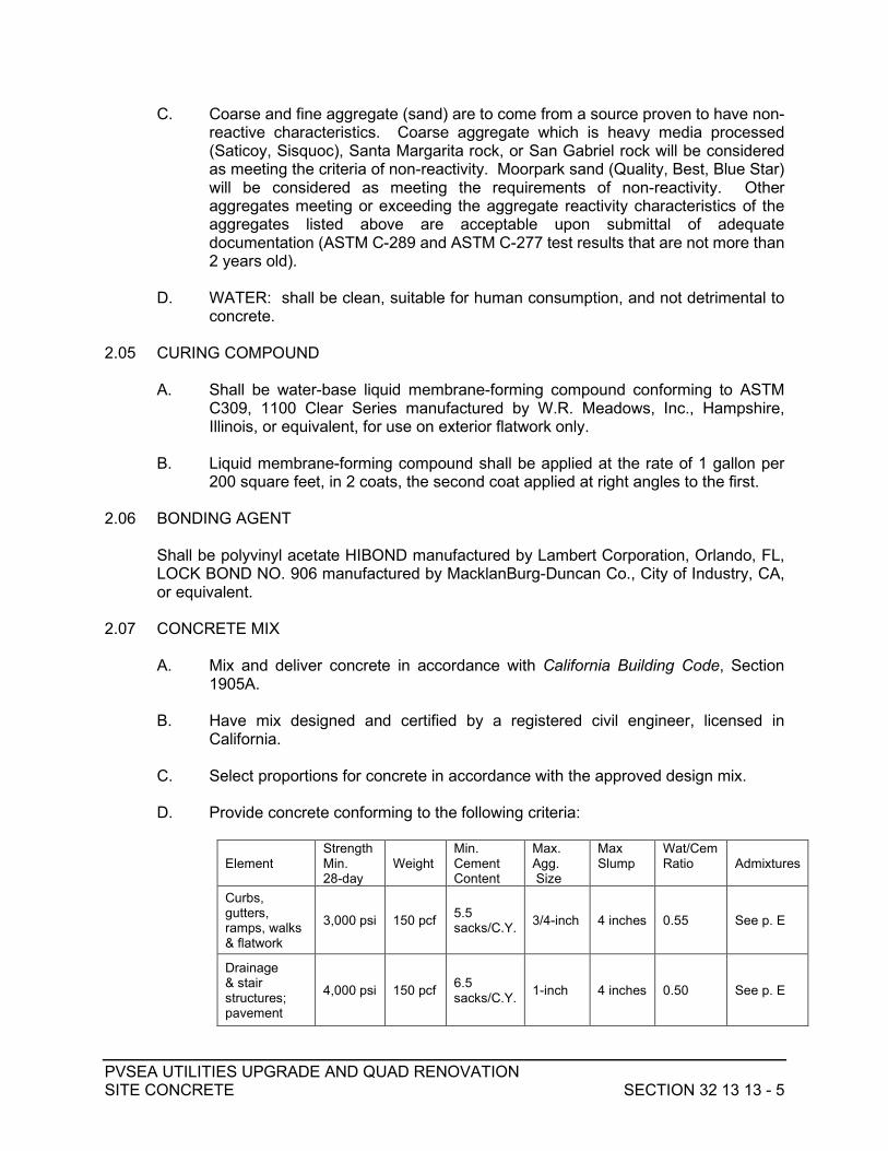
PVSEA UTILITIES UPGRADE AND QUAD RENOVATION SITE CONCRETE SECTION 32 13 13 - 5
C. Coarse and fine aggregate (sand) are to come from a source proven to have non-reactive characteristics. Coarse aggregate which is heavy media processed (Saticoy, Sisquoc), Santa Margarita rock, or San Gabriel rock will be considered as meeting the criteria of non-reactivity. Moorpark sand (Quality, Best, Blue Star) will be considered as meeting the requirements of non-reactivity. Other aggregates meeting or exceeding the aggregate reactivity characteristics of the aggregates listed above are acceptable upon submittal of adequate documentation (ASTM C-289 and ASTM C-277 test results that are not more than 2 years old).
D. WATER: shall be clean, suitable for human consumption, and not detrimental to
concrete. 2.05 CURING COMPOUND
A. Shall be water-base liquid membrane-forming compound conforming to ASTM
C309, 1100 Clear Series manufactured by W.R. Meadows, Inc., Hampshire, Illinois, or equivalent, for use on exterior flatwork only.
B. Liquid membrane-forming compound shall be applied at the rate of 1 gallon per
200 square feet, in 2 coats, the second coat applied at right angles to the first. 2.06 BONDING AGENT
Shall be polyvinyl acetate HIBOND manufactured by Lambert Corporation, Orlando, FL, LOCK BOND NO. 906 manufactured by MacklanBurg-Duncan Co., City of Industry, CA, or equivalent.
2.07 CONCRETE MIX
A. Mix and deliver concrete in accordance with California Building Code, Section 1905A.
B. Have mix designed and certified by a registered civil engineer, licensed in
California. C. Select proportions for concrete in accordance with the approved design mix. D. Provide concrete conforming to the following criteria:
Element
Strength Min. 28-day
Weight
Min. Cement Content
Max. Agg. Size
Max Slump
Wat/Cem Ratio
Admixtures
Curbs, gutters, ramps, walks & flatwork
3,000 psi 150 pcf 5.5 sacks/C.Y. 3/4-inch 4 inches 0.55 See p. E
Drainage & stair structures; pavement
4,000 psi 150 pcf 6.5 sacks/C.Y. 1-inch 4 inches 0.50 See p. E

PVSEA UTILITIES UPGRADE AND QUAD RENOVATION SITE CONCRETE SECTION 32 13 13 - 6
E. Include the following admixtures: 1. 1.5% air entrainment 2. 15% fly ash, Type N or F only 3. Low range water reducer
F. The use of a pea gravel mix (3/8” aggregate) concrete is expressly prohibited. 2.08 EXPANSION JOINT
A. Filler material shall be preformed bituminous type conforming to ASTM Standard D-1751.
B. Dowel tubing shall be plastic SPEED DOWEL supplied with sacrificial plate for
attaching to form, as supplied by Aztec Concrete Accessories, or approved equivalent.
2.09 REMOVABLE JOINT CAP
A. High impact polystyrene, depth equal to width of expansion joint filler, supplied in 10-foot lengths, as manufactured by Concrete Tie, or equivalent.
B. Where polyurethane sealant primers are used, a bondbreaker tape shall be applied
prior to caulking. 2.10 JOINT SEALANT
For crack-control and expansion joints shall be chemical-cure, two-component, polyurethane-base, non-sag elastomeric Sikaflex-2cNS manufactured by Sika Corporation, Lyndhurst, NJ, or approved equivalent. Color: Limestone Grey.
2.11 ABRASIVE STAIR NOSING
A. PRODUCT: Type 231BF (3 inch wide) by Wooster or approved equivalent by Balco or American Safety Tread.
B. COLOR: Safety Yellow for Drop-Off / Loading Isle Curb, Black for Exterior Stairs
and Steps, or as required by Architect; confirm in advance. Color used must provide 70% contrast from color of curb or stair tread surface.
C. LENGTH: Length of stair tread or of Drop-off / Loading Isle curb, less 3 inches on
each end. 2.12 NON-SLIP PAINT
A. PRODUCT: For visually impaired warning strips shall be EPOTUFF ES-83 Epoxy as manufactured by No Skidding Products, Inc. [(416) 667-1783], or approved equivalent.

PVSEA UTILITIES UPGRADE AND QUAD RENOVATION SITE CONCRETE SECTION 32 13 13 - 7
B. COLOR: Safety Yellow for Drop-Off / Loading Isle Curb (special order), Black for Exterior Stairs and Steps, or as required by Architect; confirm in advance. Color used must provide 70% contrast from color of curb or stair tread surface.
2.13 EPOXY, FLATWORK DOWELS
Epoxy used for grouting rebar dowels to maintain joint integrity between site flatwork components (curbs, gutters, walkways, ramps) shall be Simpson SET-XP Adhesive, ICC No. ESR-2508, or equivalent. Pull tests are not required.
2.14 WATERPROOFING
A. Shall be MERLEX SUPER BLOCKADE cement-based coating as supplied by Concrete Tie Co., Ventura, CA, or approved equivalent, applied in two coats.
B. Color of first coat: white; color of second coat: gray.
2.15 SKATEBOARD DETERRENT DEVICES
A. Grinder Minders as manufactured by Grind To A Halt, Inc., or equivalent, with brushed stainless steel finish.
B. Install in strict accordance with manufacturer’s specified procedures. C. Install skate stop devices on raised curbs and walls contiguous with or adjacent to
paved walking and driving surfaces, unless waived in writing by the Districts. Skate stop devices shall not be installed where top of curb or wall is part of a walking surface and could result in a trip hazard (such as pavement edge curb flush with contiguous sidewalk).
D. On ramps, install skate stop devices on edge curbs and walls centered between
each pair of handrail posts, not to exceed 4’ spacing, continuous the full length of the ramp. Adjust spacing as necessary to clear edge of expansion, construction, or crack control joint by 3 inches.
E. On curbs and walls not containing rail posts, install skate stop devices located 18”
from end of, or angle point in, curb / wall and at 36” maximum spacing continuous along full length of curb / walls.
F. Provide Shop Drawing detailing proposed locations of all skate stop devices for
review and approval in advance of installation. 2.16 DETECTABLE WARNING PAVERS
A. MANUFACTURER: Wausau Tile, or equivalent. B. PRODUCT: Precast Concrete Truncated Dome ADA Compliant Warning Paver. C. COLOR: Terra Cotta.

PVSEA UTILITIES UPGRADE AND QUAD RENOVATION SITE CONCRETE SECTION 32 13 13 - 8
D. APPLICATION: Subject to vehicular traffic loading. E. INSTALLATION: In accordance with manufacturer’s recommendations.
PART 3 EXECUTION 3.01 PROTECTING EXISTING CONCRETE AT SAWCUT
A. After marking location of proposed sawcut on existing concrete improvement surface but before cutting, document condition of concrete along sawcut line; provide photographic record to Owner’s Representative, with any existing damage highlighted.
B. Protect integrity of sawcut line and existing concrete improvements to remain
behind sawcut line until construction of conforming improvements. C. If existing concrete is broken-off or otherwise damaged along or behind sawcut
line before new concrete is placed, sawcut a new conform line parallel with, full length of, and sufficient distance behind original sawcut line so as to remove damaged concrete and / or irregularity along conform line and replace, at no additional cost to Owner.
D. Overcutting is not allowed in sawcutting of existing concrete pavement and
flatwork; the saw shall be stopped short of an overcut and the remainder of the cut constructed by drilling, to make a smooth, clean corner.
3.02 GRADING PROCEDURE UNDER SITE CONCRETE IMPROVEMENT AREAS
A. These grading procedures apply to all areas within, and extending a minimum of 1 foot outside of, the limits of asphalt or concrete pavement and the limits of curb, gutter, sidewalk, ramps, and stairs.
B. Excavate existing soil to a depth which removes all existing non-complying fill and
disturbed natural soils, as determined by the Construction-Phase Geotechnical Engineer, or to the bottom of the proposed base course, whichever is deeper.
C. Before proceeding with scarification and recompaction of soil below subgrade
level, request observation and testing of surfaces exposed per Paragraph 3.02B hereinabove by Construction Phase Geotechnical Engineer who will determine: 1. Whether or not scarification and recompaction should be performed.
Scarification of soil to 9” below subgrade elevation and recompaction to minimum 95% of maximum density is required unless otherwise recommended in writing during construction by the Geotechnical Engineer.
2. Whether or not stabilization of subgrade soils pursuant to Paragraph 3.02H hereinbelow is necessary. If yielding subgrade warranting stabilization is observed, corrective measures will be recommended by Geotechnical Engineer and direction for proceeding given by District as extra work pursuant to provisions of the Contract Documents.

PVSEA UTILITIES UPGRADE AND QUAD RENOVATION SITE CONCRETE SECTION 32 13 13 - 9
D. For fill required to achieve subgrade elevations, use on-site soil, or imported soil meeting the requirements of the Geotechnical Engineer for fill material. Condition, place, and compact this material to minimum 90% of maximum density to a level at least 9 inches below sand or aggregate base material. Compact remaining fill to bottom of sand or aggregate base material to minimum 95% of maximum density.
E. Moisten or dry scarified soil and fill material to near the optimum moisture content
before compacting. F. For those areas where specific thicknesses of surfacing and base courses are
given on the Detail Drawings, finish grading to required subgrade elevations.
G. For those areas where estimated thicknesses of surfacing and base courses are given on the Detail Drawings, bring the areas to rough subgrade elevations based on the estimated thicknesses; request determination by the Construction-Phase Geotechnical Engineer of actual thickness of pavement surfacing and base courses based on the results of R-Value tests to be conducted on the rough subgrade material and the Traffic Index(es) shown on the Detail Drawings; perform additional grading if necessary to adjust subgrade elevations to accommodate the final pavement structural section thickness.
H. Proof-roll finish subgrade with heavy, rubber-tired construction equipment under
the observation of the Construction-Phase Geotechnical Engineer; surface shall be firm and unyielding. Address yielding or overwet / pumping subgrade areas as recommended by the Construction-Phase Geotechnical Engineer.
I. Request observation and testing of finish subgrade condition by Construction-
Phase Geotechnical Engineer and do not proceed with paving operations until subgrade condition has been approved.
3.03 FORMWORK
A. Verify lines, grades and dimensions and bring all discrepancies to the attention of the Architect / Engineer for resolution before proceeding with formwork.
B. Where it will not be exposed to view, foundation concrete may be placed directly
into neat excavations (earth forms) provided the foundation trench walls are firm and stable, as determined by the engineer and the geotechnical engineer, and such placement is approved by the Division of the State Architect and the Owner’s Representative.
C. Where earth forms are allowed to be used, cut excavations neatly and accurately
to size for placement of concrete directly against the excavation and, except for bottom of footings, trim the excavation to allow for one inch of additional concrete beyond the dimensions or profiles shown on the Drawings. Hand trim sides and bottom of excavation, remove debris and loose soil, and construct formwork along each side of excavation at top to secure reinforcing and prevent sloughing; the minimum form work shown on the Drawings is mandatory to insure a clean excavation immediately prior to and during placement of concrete.

PVSEA UTILITIES UPGRADE AND QUAD RENOVATION SITE CONCRETE SECTION 32 13 13 - 10
D. Request observation and testing of Finish Subgrade condition by Construction Phase Geotechnical Engineer and do not proceed with placement of base material, form work, or reinforcing until subgrade condition has been approved.
E. For concrete pavement, confirm that finish base course has been constructed to
the design elevation, slope, and cross section within tolerances specified in Section 312000, Subsection 3.03B, pursuant to Section 015100 Field Engineering. Reconstruct and reconfirm as necessary for conformance before proceeding with placement of surfacing.
F. Where called for, place base material and compact to minimum 95% density of
maximum density. Request observation and testing and do not proceed with form work or reinforcing until thickness and compaction density of base material have been approved.
G. Erect formwork, shoring and bracing to achieve design requirements, in
accordance with Section 1906A, California Building Code. 1. Remove old concrete which is set and dry from form boards. 2. Provide bracing to ensure stability of formwork and shore or strengthen
formwork subject to overstressing by construction loads. 3. Arrange and assemble formwork, bracing, and shoring to permit
dismantling and stripping without damage to concrete. 4. Minimize the number of form joints; align joints and make watertight. 5. Provide chamfer strips on external corners where called for on Detail
Drawings. 6. Layout joint spacing and mark on forms and request review by Owner’s
Representative.
H. Protect staff, personnel and public from harm and accident during formwork. Conform to California Code of Regulations, Title 8, Subchapter 4, Construction Safety Orders.
3.04 POUR STOPS
A. Construct separate concrete pours at all expansion joints and elsewhere as called for on the plans (pour stops). At least 48 hours shall separate concrete placement on each side of pour stop.
B. At expansion joints serving as pour stops, edge of first pour shall be formed and
speed dowel tubes installed. Expansion joint filler with removable joint cap shall serve as form for grade control and for tooling edge of second pour.
3.05 REINFORCEMENT
A. Fabricate steel reinforcement in accordance with the Detail Drawings and Specifications. Where not detailed or specified, comply with the applicable requirements of Section 1907A of the California Building Code and the American Concrete Institute SP-66-88.

PVSEA UTILITIES UPGRADE AND QUAD RENOVATION SITE CONCRETE SECTION 32 13 13 - 11
B. Bend, cut, and place bars accurately. Bend bars cold at the mill; heating or field-bending of bars is not permitted. Do not bend or straighten bars in any manner that will damage the material.
C. Place, support, and secure reinforcement against displacement during pouring and
consolidating concrete.
D. Unless otherwise noted on Drawings, coverage for reinforcing bars (to face of bar) shall be as follows: 1. Concrete in contact with earth, unformed: 3” 2. Concrete in contact with earth, formed: 2” 3. Wall, exterior face, #5 bar and smaller: 1 ½” 4. Wall, exterior face, #6 bar and larger: 2” 5. Structural slab: ¾”
3.06 PLACING CONCRETE
A. Construct concrete improvements in accordance with the Drawings, Detail Drawings, and Specifications.
B. Prior to scheduling concrete pour:
1. Have excavation, form work and reinforcement reviewed and accepted by Owner’s Representative.
2. Have joint layout, as marked on forms in advance, reviewed and accepted by Owner’s Representative.
3. Where required gutter gradient is less than 1.0% (1/8 inch per foot), have a Licensed Surveyor confirm form elevations prior to ordering concrete.
4. If there has been rainfall or other discharge of water to excavations after observation and testing pursuant to Paragraph 3.02F hereof, have subgrade re-reviewed and approved by Construction Phase Geotechnical Engineer.
C. Notify Architect, Engineer, Structural Engineer, and Geotechnical Engineer /
Testing Laboratory minimum 24 hours prior to commencement of concrete placement.
D. PRIOR TO PLACING CONCRETE:
1. Carefully review excavation, form work, and reinforcement. Remove wood chips, debris, and loose soil; take out temporary bracing and cleats, box openings for pipes; secure forms, reinforcement, anchors, and embedded items in their proper places.
2. Dampen forms and sides and base of excavation against which concrete will be placed by spraying with clean water; apply water sufficient to dampen forms / excavation while not causing erosion or standing water.
3. Before placing new concrete against hardened concrete and before placing masonry on concrete, remove all incrustations and laitance from forms, reinforcing, and surface of hardened concrete. If the surface mortar and laitance of the first concrete pour has not been completely removed by water blasting, sandblast the hardened concrete surface to expose the coarse aggregate to ¼ inch amplitude. Surfaces which are to receive drypack shall also be prepared as herein specified.

PVSEA UTILITIES UPGRADE AND QUAD RENOVATION SITE CONCRETE SECTION 32 13 13 - 12
E. HANDLING AND PLACING: 1. Once concrete placement has started, carry on as a continuous operation
until the section of approved size and shape is completed. 2. Handle concrete as rapidly as practicable from the mixer to the place of
final deposit by methods which prevent the separation or loss of ingredients. Deposit concrete as neatly as practicable, in its final position to avoid rehandling or flowing.
3. Concrete shall not be dropped freely where reinforcing will cause segregation, nor shall it be dropped freely more than 4 feet.
4. Maintain plastic surface approximately horizontal. 5. Do not deposit concrete that has partially hardened in the work. Do not
retemper or use concrete after having stood 15 minutes after leaving the truck or mixer.
6. The total elapsed time between addition of water at the batch plant and complete discharge of the concrete load at the site shall not exceed 90 minutes.
7. Thoroughly vibrate all concrete within 15 minutes after placement.
F. VIBRATING AND COMPACTING: 1. Thoroughly consolidate concrete and compact by suitable means during
the operation of placing and depositing. Thoroughly work concrete around reinforcement, embedded items, and into the corners of the forms. Thoroughly vibrate concrete adjacent to forms. Use internal vibrators under experienced supervision and keep out of contact with reinforcement and wood forms.
2. Vibrate close to the forms but do not continue at one spot to the extent that large areas of grout are formed, or the heavier aggregates are caused to settle. Take care not to disturb concrete which has taken its initial set.
3.07 PROTECTION AND CURING
A. GENERAL: Protect freshly deposited concrete from premature drying and excessively hot or cold temperatures and maintain without drying at a relatively constant temperature for the period of time necessary for the hydration of the cement and proper hardening of the concrete.
B. INITIAL CURING: Initial curing shall immediately follow the finishing operation.
Keep concrete continuously moist at least overnight. Use one of the following materials or methods: 1. Ponding or continuous sprinkling. 2. Use of curing compounds: Apply compounds in accordance with the
manufacturer’s recommendations. Do not use on surfaces against which additional concrete or other cementitious finishing materials are to be bonded or on surfaces on which such curing is prohibited by these specifications.
C. FINAL CURING: Immediately following the initial curing and before the concrete
has dried, accomplish additional curing using one of the following materials or methods: 1. Continuing the method used in initial curing. 2. Waterproof paper covering. 3. Other moisture-retaining coverings as approved.

PVSEA UTILITIES UPGRADE AND QUAD RENOVATION SITE CONCRETE SECTION 32 13 13 - 13
D. DRILLING AND CORING: Drilling for anchors such as for skate stop devices and coring for post embedment shall not take place sooner than 28 days after placement of concrete.
3.08 WATERPROOFING
A. Prepare the surface as recommended by the manufacturer of the waterproofing material.
B. Apply the waterproofing to the limits identified on the Drawings and Detail
Drawings in strict accordance with the manufacturer’s recommendations. C. For brush-applied material, apply in two coats with delay between coats as
recommended by the manufacturer; color of first coat shall be white and of second coat shall be gray.
3.09 EXISTING WORK
A. Overcutting is not allowed in sawcutting of existing concrete pavement and
flatwork; at changes in direction, stop the saw short of an overcut and drill to make a smooth, clean corner.
B. Where new concrete is dowelled to existing work, drill holes in existing concrete,
insert steel dowels and set with epoxy grout. C. Prepare previously placed concrete by cleaning with steel brush and apply bonding
agent in accordance with manufacturer’s instructions. 3.10 COLORED WALKWAYS AND FLATWORK [IF CALLED FOR ON PLANS]
A. Conform to Architect's requirements for color, finish, and joint / scoreline pattern. B. Construct a mockup for approval by Architect for each color required. Mockups
shall contain an expansion joint, a control joint, and scorelines and shall be minimum of 10-feet long for walkways and minimum of 20-feet square for flatwork areas.
C. Do not construct permanent colored concrete improvements without approval of
mockup by Architect. If approved, mockup may remain as part of permanent work, provided it also conforms to all dimensional, structural, and geotechnical requirements.
3.11 CONCRETE FINISHES
A. FORMED SURFACES: smooth finish. B. SIDEWALKS, RAMPS, EXTERIOR SLABS, PAVEMENTS: broom finish
transverse to path of travel; medium broom (medium salt) where surface slope is less than 6%, heavy broom (slip resistant) where surface slope is 6% or greater, conforming to CBC Section 1133B.7.1. Finishes shall be uniform throughout project.

PVSEA UTILITIES UPGRADE AND QUAD RENOVATION SITE CONCRETE SECTION 32 13 13 - 14
C. WATERPROOFING: 1. Where waterproofing is called for on the Drawings, apply it in accordance
with the manufacturer's instructions in two coats; apply the second coat at right angles to the first.
2. Mask the interface line along finish grade to prevent application of waterproofing above grade.
3.12 JOINTS: CURB, CURB & GUTTER, GUTTER, WALK, RAMP
A. CRACK CONTROL JOINTS 1. Construct joints during the finishing operation in accordance with the Detail
Drawings and these specifications. 2. Construct transverse Crack Control Joints (deep-tooled weakened-plane
joints) at regular intervals not exceeding 10-feet, directly above drainpipes which outlet through curb, and at locations called for on the Drawings or by the Owner's Representative. Longitudinal reinforcement shall be continuous through joint.
3. Construct joints as follows: after preliminary troweling, part the concrete to a depth of 2 inches with a straightedge to create a division in the coarse aggregate. Then refloat the concrete to fill the parted joint with mortar. Mark the form headers to locate the weakened plane for final joint finishing, which shall be accomplished with a jointer tool having a depth of ½ inch and a radius of 1/8 inch. The finished joint opening shall not be wider than 1/8 inch.
B. EXPANSION JOINTS
1. Construct transverse Expansion Joints at BCR, ECR, and at regular intervals not exceeding 40-feet. Construct additional expansion joints along edges of driveways and fixed objects and structures (fire hydrant, light standard, utility pole, drain inlet, manhole or valve cover, screen/retaining wall, building wall, etc.) and at locations called for on the Drawings or by the Owner's Representative. Do not construct Expansion Joints in cross or valley gutter which is separate from curb. Construct joints in accordance with the Detail Drawings and these Specifications.
2. Construct expansion joints ⅜-inch wide with one piece of preformed joint filler installed from bottom of slab to within ⅝-inch of concrete surface; install a ⅜-inch deep removable joint cap on the filler with the top of cap ¼-inch below concrete surface; fill resulting reservoir with joint sealant to within ¼-inch of concrete surface as soon after completion of the curing period as is possible. Joints shall be cleaned of all foreign material, including membrane curing compounds and all of the removable portion of the joint cap, and shall be surface-dry when sealer is installed.

PVSEA UTILITIES UPGRADE AND QUAD RENOVATION SITE CONCRETE SECTION 32 13 13 - 15
3. Interrupt longitudinal reinforcing bars 3 inches clear of expansion joints and install minimum 16-inch long smooth dowels across, and centered on, the joint. Install one-half (one end) of dowel within a "Speed Dowel" tube; provide a 1-inch gap between the end of the dowel and the sealed end of the tube. For walks, ramps, and flatwork, install 5/8” dowels centered vertically in slab and centered horizontally between each pair of longitudinal rebar. For curbs and curb and gutters, install ¾” dowels centered between pairs of longitudinal rebar, horizontal and vertical (1 dowel for curb, 2 dowels for curb and gutter). Omit smooth dowels at BCR and ECR when curb radius is less than 5 feet.
C. Adjust joint spacing as necessary to align with those already constructed in existing
adjacent (contiguous) features. D. Along curves and through walk returns, joints shall be radial.
3.13 JOINTS: CONCRETE PAVEMENT
A. CRACK CONTROL JOINTS 1. Construct joints by sawcutting grooves as soon as concrete has hardened
sufficiently to support the saw and the saw will not dislodge the concrete, but before six (6) hours after finishing of the concrete. An early entry saw such as the “Soff-Cut” saw by Soff-Cut International (800) 776-3328 is recommended.
2. Construct transverse and longitudinal Crack Control Joints (Contraction Joints) at regular intervals not exceeding 10-foot maximum spacing each way and at additional locations called for on the Drawings or by the Owner’s Representative. Construct joints in accordance with the Detail Drawings and these Specifications. Width of joints shall be ¼-inch, depth shall be 2 inches.
3. Fill sawcut joints with joint sealant to within ¼" of concrete surface as soon after completion of the curing period as is feasible and before pavement is opened to traffic. Joints shall be cleaned of all foreign material, including membrane curing compound, and shall be surface-dry when sealer is installed.
B. EXPANSION JOINTS
1. Construct Expansion Joints at locations called for on the Drawings or by the Owner’s Representative. Construct joints in accordance with the Detail Drawings and these Specifications.
2. Construct expansion joints ½-inch wide with one piece of preformed joint filler installed from bottom of slab to within 1½" of concrete surface; fill resulting reservoir with backer rod and joint sealant to within ¼" of concrete surface as soon after completion of the curing period as is feasible and before pavement is opened to traffic. Joints shall be cleaned of all foreign material, including membrane curing compound, and shall be surface-dry when sealer is installed.

PVSEA UTILITIES UPGRADE AND QUAD RENOVATION SITE CONCRETE SECTION 32 13 13 - 16
3. Interrupt reinforcing bars 3 inches clear of expansion joints and install minimum 18-inch long smooth dowels across, and centered on, the joint. Dowel diameter shall be 1 inch for 8 inch thickened slab, 1 ¼ inches for 10 inch thickened slab. Install one-half (one end) of dowel within a "Speed Dowel" tube; provide a 1-inch gap between the end of the dowel and the sealed end of the tube. Install dowels centered vertically in the thickened slab and centered horizontally between each pair of longitudinal rebar.
C. Adjust joint spacing as necessary to align with those already constructed in existing
adjacent (contiguous) curb, gutter, and sidewalk. D. Along curves, joints shall be radial.
3.14 REINFORCING STEEL
A. Install reinforcing steel in concrete improvements in accordance with the Detail
Drawings. B. Install reinforcing steel continuous through construction joints with a minimum 24-
inch lap. C. Interrupt reinforcing steel at expansion joints and construct dowels across joints in
accordance with Paragraphs 3.12-B and 3.13-B of this Section and the Detail Drawings.
3.15 ADJUSTING STRUCTURES
Carefully adjust the perimeter edge of valve box, utility vault, and manhole frames and covers to conform with finish pavement surface.
3.16 SIGN POSTS
Where sign post is to be installed in concrete pavement or walkway, accurately locate post and construct footing per the Detail Drawing monolithically with pavement or walkway. After concrete has cured, core drill and install sign post per the Detail Drawing.
3.17 FIELD QUALITY CONTROL
A. Request inspection by Owner's Representative after forming and placing
reinforcing steel and after marking joint / scoreline locations on forms but prior to scheduling the concrete pour. Provide at least 24-hours advance notice.
B. The total elapsed time between addition of water at the batch plant and complete
discharge of the concrete load at the site shall not exceed 90 minutes. Thoroughly vibrate all concrete within 15 minutes after placement. C. Overcutting is not allowed in sawcutting of existing concrete pavement and
flatwork; the saw shall be stopped short of an overcut and the remainder of the cut constructed by drilling, to make a smooth, clean corner.

PVSEA UTILITIES UPGRADE AND QUAD RENOVATION SITE CONCRETE SECTION 32 13 13 - 17
D. Survey forms for concrete walks and ramps prior to ordering concrete to ensure that accessibility requirements for slope and cross-slope will be conformed with.
E. Where design longitudinal gradient is less than 1% (1/8 inch per foot) survey gutter
or curb and gutter forms prior to ordering concrete to ensure that design slope is being achieved.
F. ACCEPTABLE TOLERANCES:
1. Formed concrete features shall not vary more than 1/4 inch (0.02 foot) from design dimension (height, width, or length) at any location.
2. Formed concrete features shall not vary more than 1/4 inch (0.02 foot) from design line or grade at any location or along any 10’ length.
3. The faces of curbs and walls shall not vary more than 1/4 inch (0.02 foot) above or below the surface plane called for by the Drawings and Detail Drawings.
4. The surface of concrete walks, ramps, and pavements shall be finished true to grade and cross section and shall be free of any unevenness greater than ¼ inch (0.02 foot) when checked with a 10-foot long straight edge placed on the surface.
5. In no case shall water pond in gutters or on concrete walks, pavement, and flatwork. Ponded water is defined as that which covers a 5 cent piece after area is flooded and allowed to drain for one hour at 70º F or warmer.
6. In no case shall maximum accessible slopes or cross-slopes be exceeded.
3.18 FLOOD TEST
A. After construction of concrete site improvements including walks, steps, ramps, flatwork, pavement, and gutters, conduct a flood test to review surface drainage, as follows: 1. Supply and discharge water in sufficient quantity to completely wet and
cover all site concrete surfaces including gutter areas and allow to drain/dry for one hour at 70º F or warmer. Mark the outline limits of residual standing water deep enough to cover a 5 cent piece with non-permanent marking crayon.
2. Remove and replace site concrete improvements at no additional cost to the Owner, as necessary to provide positive surface drainage and to prevent ponding of water on surfaces and in gutters; removal and replacement shall be to the closest joint each way limits of from ponding.
3. Conduct additional flood testing to confirm success of corrective measures.
3.19 DEFECTIVE WORK
Defective concrete work shall be removed and replaced at Contractor’s expense. 3.20 SUBMITTAL REQUIREMENTS AND SCHEDULE
A. Include this form with submittals of this Specification Section, unless a substitute
product is being proposed, in which case refer to Division 1, "Substitutions" section, for substitution requests.

PVSEA UTILITIES UPGRADE AND QUAD RENOVATION SITE CONCRETE SECTION 32 13 13 - 18
Contractor's [Contractor is to acknowledge with initials each submittal included] Initials: ____ Letter of explanation attached for each submittal not included. ____ All submitted products are as specified.
B. SUBMITTAL SCHEDULE
1. Product Information ____ a. Submit concrete mix design for each class of concrete required.
b. Submit laboratory test results for all aggregate sources which confirm conformance with Paragraph 2.04 hereof.
____ c. Submit laboratory test results for aggregate base which confirm conformance with grading and quality requirements of Section 200-2.2 of the SSPWC.
____ d. Submit sieve analysis and Sand Equivalent value for sand base. ____ e. Submit mill affidavits stating the grades and physical and
chemical properties of the reinforcing steel and conformance with ASTM Specifications.
____ f. Submit manufacturer's product data for joint filler, backer rod, and sealant, for epoxy grout, for waterproofing, for curing
compound. ____ g. Submit manufacturer's product data for abrasive stair nosing. ____ h. Submit manufacturer's product data for non-slip paint for
warning strips. i. Submit manufacturer’s product data for skateboard deterrent
devices. j. Submit manufacturer’s product data for precast concrete detectable
warning pavers. 2. Shop Drawings
a. Prepare and submit shop drawings, drawn to scale, showing an elevation view of all retaining structures and detailing the locations of structure joints and form joints and snap tie layout.
b. Prepare and submit shop drawings, drawn to scale, detailing locations of skateboard deterrent devices.
END OF SECTION 32 13 13

PVSEA UTILITIES UPGRADE AND QUAD RENOVATION SITE CONCRETE REINFORCEMENT SECTION 32 13 14 - 1
SECTION 32 13 14 SITE CONCRETE REINFORCEMENT
PART 1 GENERAL 1.01 DESCRIPTION
A. Provide materials, equipment and transportation and perform labor as required for supplying reinforcing steel for cast-in-place concrete pavement, curbs, gutters, walkways, ramps, drainage structures, retaining structures, post footings.
B. This work does not include concrete reinforcement associated with the
building(s). 1.02 RELATED DOCUMENTS
Drawings and general provisions of the Contract, including General and Supplementary Conditions and other Division 1 Specification Sections, apply to this Section.
1.03 RELATED WORK SPECIFIED ELSEWHERE
Section 32 13 13 – Site Concrete 1.04 REFERENCE SPECIFICATIONS
A. ACI SP 66 – Detailing Manual B. ACI 318 – Building Code Requirements for Reinforced Concrete C. ASTM A 82 – Steel Wire, Plain, for Concrete Reinforcement D. ASTM A 615 – Deformed and Plain Billet-steel for Concrete Reinforcement E. CRSI MSP-1 – Manual of Standard Practice F. California Building Code, Chapter 19, Concrete
1.05 REGULATORY REQUIREMENTS
Construction shall comply with the California Code of Regulations, Title 24, Part 2 (the California Building Code), most recent effective edition.
1.06 SUBMITTALS
A. Provide submittals according to the Conditions of the Contract and Division 1 “Submittal Procedures” section.
B. Refer to “Submittal Requirements and Schedule” at the end of this Section.

PVSEA UTILITIES UPGRADE AND QUAD RENOVATION SITE CONCRETE REINFORCEMENT SECTION 32 13 14 - 2
1.07 RECORD DOCUMENTS
A. Comply with requirements of Division 1, “Project Record Documents” section, and following: 1. Accurately record changes in construction from that called for on the
Drawings and Specifications for Record Documents.
1.08 QUALITY ASSURANCE A. All reinforcing shall be fabricated from steel manufactured in the United States. B. Specified reinforcing bars shall be supplied from single sources only.
1.09 TESTS
Testing and analysis of reinforcing steel will be performed under provisions of Division 1, “Testing and Inspection” section.
1.10 DELIVERY, HANDLING AND STORAGE
A. DELIVERY: 1. Deliver bars new and free from rust and mill scale in original bundles
tagged to identify placement and certify testing. 2. If reinforcement arrives at the site without tags or certificates, testing by
the Owner's testing laboratory will be required in accordance with Division 1, “Testing and Inspection” section or such reinforcement will not be accepted for incorporation into the Project; Contractor shall reimburse the Owner for the costs of such tests.
B. HANDLING AND STORAGE
1. Transport reinforcing steel to the construction site; store and cover it in a manner which will ensure that no damage occurs from moisture, dirt, grease, or other cause that might impair bond to concrete.
2. Store a sufficient supply of approved reinforcing steel on the construction site at all times to ensure that there will be no delay in construction.
3. Maintain identification of steel after bundles are broken. 1.11 COORDINATION
Review architectural, structural, and civil drawings for anchor bolt schedules and for locations of anchors, inserts, conduits, sleeves, and other items which are required to be cast in concrete, and make necessary provisions as required so that reinforcing steel will not interfere with the placement of such embedded items.
PART 2 PRODUCTS 2.01 REINFORCING BARS
New, deformed billet-steel bars, complying with ASTM A-615, grades as indicated on the drawings.

PVSEA UTILITIES UPGRADE AND QUAD RENOVATION SITE CONCRETE REINFORCEMENT SECTION 32 13 14 - 3
2.02 ACCESSORIES
Provide reinforcement accessories, consisting of spacers, chairs, ties, and similar items as required for spacing, assembling, and supporting reinforcement in place. Provide accessories fabricated from galvanized steel or approved plastic material, conforming to the applicable requirements of CRSI MSP-1.
2.03 TIRE WIRE
Galvanized steel wire conforming to ASTM A-82, except black steel may be used for concealed concrete work; 16 gauge, except heavier where indicated on the Drawings. Tie wire shall not protrude from concrete.
PART 3 EXECUTION 3.01 FABRICATION
A. Fabricate steel reinforcement in accordance with the details indicated. Where specific details are not indicted or noted, comply with the applicable requirements of CBC, Chapter 19, and ACI SP-66.
B. Bend, cut, and replace bars accurately, as indicated. Bend bars cold at the mill;
heating or field bending of bars is not permitted. Do not bend or straighten bars in any manner that will injure the material. Bars that have been heated for bending, bars with kinks or bends not indicated on the Drawings, and bars damaged by bending or straightening shall be removed, and new reinforcement shall be provided.
3.02 PLACING
A. GENERAL: Place reinforcing steel in accordance with the Drawings and the applicable requirements of CRSI MSP-1 and ACI 318. Install reinforcement accurately and secure against movement, particularly under the weight of workmen and the placement of concrete.
B. REINFORCING SUPPORTS: Support bars on metal chairs or spacers on metal
hangers, accurately placed and securely fastened to steel reinforcement in place. Support legs of accessories in forms without embedding in form surface. Space chairs and accessories in conformance with CRSI MSP-1. No wood will be permitted inside forms. Precast concrete cubes may be used to support reinforcing for footings and slabs on grade only.
C. PLACING AND TYING: Set reinforcing in place, space, and securely tie at
splices and at crossing points and intersections in the position indicated, or as directed. Point ends of wire away from forms.

PVSEA UTILITIES UPGRADE AND QUAD RENOVATION SITE CONCRETE REINFORCEMENT SECTION 32 13 14 - 4
D. SPACING: Space bars as indicated. Where not indicated, the clear spacing for main longitudinal column reinforcement shall be not less than 1.5 times the nominal bar diameter, or 1-1/2 inches, or 1-1/3 times the maximum size aggregate, whichever is greater. For other parallel bars, where spacing is not indicated, the minimum clear spacing shall not be less than the nominal bar diameter, or one inch, or 1-1/3 times the maximum size aggregate, whichever is less. The clear distance limitations above also apply between the bars being spliced at a contact lap splice and adjacent bars.
E. SPLICES: Except for temperature bars in slabs and horizontal wall reinforcing,
no splicing will be allowed for reinforcing bars unless detailed locations are indicated, or approval is given. Wherever possible, stagger splices of adjacent bars. 1. Lapped splices shall not be used for bars larger than No. 11. Stagger
lapped splices for horizontal wall reinforcing and slab temperature bars by the required lap splice length minimum.
2. Welding of reinforcing steel will not be permitted. 3. Make mechanical butt splices in accordance with the splicing device
manufacturer's recommendations. Mechanical splices shall develop 125 percent of the specified minimum yield tensile strength of the spliced bars.
F. DOWELS: Securely tie dowels in place before concrete is deposited. In the
event there are no bars in position to which dowels may be tied, add a No. 3 minimum to provide proper support and anchorage. Bending of dowels after placement of concrete will not be permitted. Protect dowels extended for future construction from weather exposure. Strictly comply with safety law requirements for extended dowels.
G. CLEANING: At time of concrete placement, reinforcement shall be clean and
free of coatings that would impair bond to concrete; otherwise, clean reinforcing by sandblasting.
H. Daylighting of tie wires is not permitted, no exception.
3.03 FIELD QUALITY CONTROL
A. Notify the District Inspector at least 5 working days ahead of each concrete placement and do not place any concrete until all reinforcing steel has been installed and has been approved by the Inspector. Complete all reinforcing in every way by the end of the working day which precedes concrete placement. Reinforcement not placed in accordance with the Drawings shall be removed and replaced.
B. Testing and inspections are specified in Division 1, “Testing and Inspection”
section.

PVSEA UTILITIES UPGRADE AND QUAD RENOVATION SITE CONCRETE REINFORCEMENT SECTION 32 13 14 - 5
3.04 SUBMITTAL REQUIREMENTS AND SCHEDULE A. Include this form with submittals of this Specification Section, unless a substitute
product is being proposed, in which case refer to Division 1, "Substitutions" section, for substitution requests.
Contractor's [Contractor is to acknowledge with initials each submittal included] Initials: ____ ____ Letter of explanation attached for each submittal not included. ____ All submitted products are as specified.
B. SUBMITTAL SCHEDULE
1. Product Information ____ a. Submit Certified Mill Test Reports for the reinforcing bars being
provided that states the strength grade(s) and A.S.T.M. Standards to which the bars have been fabricated and that the steel used in fabrication was manufactured in the United States.
2. Shop Drawings ____ a. Prepare and submit placement drawings showing the size,
locations and spacing of reinforcing in the various parts of the structure, with details as required, in accordance with ACI SP-66. Placement drawings shall be complete so that placement of the reinforcing may proceed without reference to the design drawings. Do not submit cutting and bending lists.
END OF SECTION 32 13 14
PVSEA UTILITIES UPGRADE AND QUAD RENOVATION LANDSCAPE CONCRETE WORK SECTION 32 13 20 - 1
SECTION 32 13 20 LANDSCAPE CONCRETE WORK
PART 1 GENERAL 1.01 SECTION INCLUDES
This section includes general requirements for the concrete paving, concrete curbing, masonry wall footings, concrete bands, concrete gutters, and miscellaneous concrete work indicated on the plans. This section also includes requirements for the repair of the dry pack at the existing light pole base and the painting of the stair nosing.
1.02 QUALITY ASSURANCE
For concrete finishing, use only trained and experienced concrete finishers.
1.03 SUBMITTALS A. Mix design shall be submitted to the District Inspector for approval prior to pour. The
mix design shall show the mix identification number and the applicable proportions, weights, and quantities of Portland Cement, aggregate, water, and admixtures. The mix design submittal shall also include the size and source of aggregate, the type and source of Portland Cement, the branch and designation of admixtures, and the type of construction for which the concrete is used.
B. Submit Manufacturer’s specifications and catalog cut sheets on all specified materials
required for the concrete work
PART 2 PRODUCTS 2.01 CONCRETE
A. All concrete for this project shall be hard rock with a minimum compressive strength
at 28 days of f 'c = 3,250 PSI and conform to ASTM C-94.
B. Cement: ASTM C-150, Type I or II, low alkali. C. Aggregate: ASTM C-33, non-reactive, pea gravel. D. Slump: Maximum slump - 4 inches.
2.02 CONCRETE FINISH
A. Walks shall have a medium broom finish.
B. Concrete bands shall have a medium broom finish.
C. Concrete curbs shall be sacked smooth.
PVSEA UTILITIES UPGRADE AND QUAD RENOVATION LANDSCAPE CONCRETE WORK SECTION 32 13 20 - 2
D. Concrete steps shall have a medium broom finish.
E. Concrete gutter shall have a smooth troweled finish.
2.03 REINFORCING STEEL A. All reinforcing bars shall be free of rust, grease, mill scale or any material which might
affect its bond to concrete. All bar bends shall be made cold. B. Reinforcing steel for Concrete Work shall be deformed and shall conform to ASTM
A-615, Grade 60. No 3 bars may be grade 40. All reinforcing steel shall be positioned as indicated on Drawings.
2.04 EXPANSION JOINTS
Expansion joints shall be non-bituminous, ½” thickness, meeting ASTM Standard D-1751. (Homex 300 or equal).
2.05 CAULKED EXPANSION JOINTS Where indicated on the details, caulked expansion joints shall be constructed with ½ inch
expansion joint material with a removal cap for caulking with a self-leveling polyurethane caulk.
2.06 SCORE LINES AND EDGES Score lines shall be tooled straight with a concrete groove tool with a 3/8-inch radius.
Concrete edges shall be tooled with a concrete edging tool with a 3/8-inch radius. 2.07 CURING COMPOUND
Provide liquid curing compound, ASTM C-309, clear.
2.08 BASE
Base (rock base) shall be crushed aggregate base as per Section 200-2.2 of the SSPWC.
2.09 SEALER
Sealer shall be a water base clear penetrating sealer.
2.10 DRY PACK Dry pack shall be a stiff sand-cement mortar.
2.11 EPOXY Epoxy shall be Simpson strong tie Set-XP epoxy or equal.

PVSEA UTILITIES UPGRADE AND QUAD RENOVATION LANDSCAPE CONCRETE WORK SECTION 32 13 20 - 3
2.12 PAINTED STEP NOSING Painted step nosing shall be an acrylic elastomeric coating, Dunn-Edwards Enduralistic or
equal. Color shall be a dark brown to match the accent color on the adjacent masonry walls.
PART 3 EXECUTION 3.01 SURFACE CONDITIONS
A. Take adequate precautions for mixing, placing, finishing, curing, and protecting
concrete during unfavorable weather conditions. B. Prior to all work of this section, carefully inspect the installed work of all other trades,
and verify that all such work is complete to the point where this installation may properly commence.
C. All concrete shall be properly consolidated during placement. All reinforcing steel
and embedded items shall be securely tied in place to prevent displacement during concrete placement. Support reinforcement on blocks.
D. Verify that concrete may be placed to the lines and elevations indicated on the
Drawings, with all required clearance from reinforcement. E. Layout paving surfaces to slope and drain to planting areas or drains at a minimum
of 1%. Walkways shall not have a cross slope greater that 2% and the slope in the direction of travel shall not exceed 5%. Layout must be approved by the District Inspector prior to pour. Where concrete paving is poured adjacent to existing concrete, continue the existing slope across the new concrete section.
3.02 PREPARATION
A. Remove all wood scraps and debris from the areas in which concrete will be placed. B. Thoroughly clean the areas to ensure proper placement and bonding of concrete. C. Thoroughly wet the forms or oil them; remove all standing water. D. Thoroughly clean all transporting and handling equipment. E. Compact base to 95% relative compaction per ASTM D-1557.
3.03 PLACING CONCRETE A. Convey concrete from mixer to place of final deposit by methods that will prevent
separation and loss of materials. B. For chuting, pumping and pneumatically conveying concrete, use only equipment of
such size and design as to ensure a practically continuous flow of concrete at the delivery and without loss or separation of materials.
PVSEA UTILITIES UPGRADE AND QUAD RENOVATION LANDSCAPE CONCRETE WORK SECTION 32 13 20 - 4
C. Deposit concrete as nearly as possible in its final position to avoid segregation due to rehandling and flowing.
D. Place concrete as dry as possible consistent with good workmanship, never
exceeding the maximum specified slump. E. Place concrete at such a rate that concrete is, at all times, plastic and flows readily
between bare bars. F. When placing is once started, carry it on as a continuous operation until placement
of the panel or section is complete. G. Thoroughly consolidate all concrete by suitable means during placement, working it
around all embedded fixtures and into corners of forms. H. During placement, thoroughly compact the concrete by hand tamping and by
mechanical vibration. 3.04 TOLERANCE
Concrete planes shall be checked with a ten-foot straight-edge in two directions. There shall be no high spots or low spots greater than 1/8" in ten feet. All edges shall be straight and true.
3.05 SACKING
The face of concrete curbs shall be sacked to produce an even textured surface by filling all pits and air holes.
3.06 SCORE LINES
Score lines shall be straight and shall be of the proper alignment as shown on the Drawings.
3.07 EXPANSION JOINTS
Expansion joints shall be straight, in line, and plumb. Expansion joint material shall be set just below the concrete surface. Expansion joints shall be caulked where indicated on the details.
3.08 TOP OF FOOTINGS
Top of footings shall be rough to receive the bed-joint and first course of the masonry wall.
3.09 DEEPENED CONCRETE Deepened concrete pours are required where concrete is adjacent to pavers and where
deepened concrete is required for coring to receive handrails. Coordinate these areas with all details.
PVSEA UTILITIES UPGRADE AND QUAD RENOVATION LANDSCAPE CONCRETE WORK SECTION 32 13 20 - 5
3.10 DRY PACK Remove existing dry pack under the existing light pole base and install new dry pack. 3.11 JOINING EXISTING CONCRETE PAVING When new concrete paving joins existing concrete paving, drill and set dowels into the
existing concrete and align dowels with new paving rebars. 3.12 PAINTED STEP NOSING After the concrete steps have cured for a minimum of 20 days, apply the painted strip to the
step nosing with an elastomeric paint straight and parallel to the finish edge of the nosing. Mask to prevent any paint bleeding.
3.13 CURING AND PROTECTION
Freshly deposited concrete shall be protected from premature drying and excessively hot or cold temperatures and shall be maintained without drying at a relatively constant temperature for the period of time necessary for the hydration of the cement and proper hardening of the concrete. Apply liquid curing compound as soon as finishing is complete, within 2 hours, and in accordance with Manufacturer's directions.
END OF SECTION 32 13 13

PVSEA UTILITIES UPGRADE AND QUAD RENOVATION CONCRETE PAVERS SECTION 32 14 13 - 1
SECTION 32 14 13 CONCRETE PAVERS
PART 1 GENERAL 1.01 SECTION INCLUDES
This section includes general requirements for the installation of the concrete pavers. 1.02 SUBMITTALS
Submit four (4) samples of each concrete paver specified to the District for approval. Concrete pavers must be full size and represent the colors to be supplied.
1.03 PRODUCT HANDLING
Concrete pavers shall be delivered and unloaded at jobsite on pallets and bound in such a manner that no damage occurs to the product during hauling, handling, or unloading at the jobsite.
1.04 QUALIFICATIONS
ICPI certified installers shall be utilized for the construction of the concrete pavers. PART 2 PRODUCTS 2.01 CONCRETE PAVERS
A. Concrete pavers shall be concrete interlocking paving units and shall conform to ASTM C-936.
B. Concrete pavers shall be interlocking concrete pavers manufactured by Angelus
Block, style – Holland 60 mm, color – as per Staking Plans. C. Pattern: running bond with the three colors evenly placed throughout.
2.02 BASE
Base for interlocking pavers shall be crushed rock, 3/8” to ½” size, open graded of same size and conform to ASTM D-1863, clean free of clay particles or other contaminants.
2.03 BEDDING SAND
Bedding sand shall be clean construction sand conforming to ASTM C-33.

PVSEA UTILITIES UPGRADE AND QUAD RENOVATION CONCRETE PAVERS SECTION 32 14 13 - 2
2.04 FILTER FABRIC Filter fabric with properties equivalent to Mirafi 140N placed at top of compacted base
course and immediately beneath bedding sand leveling course. 2.05 JOINT SAND
Joint sand shall be Alliance Super Sand (polymeric sand), color beige.
2.06 PAVER SEALER
Paver sealer shall be Stain BLOCKER Invisible by BP Pro.
PART 3 EXECUTION 3.01 BASE
A. After concrete edging has cured, install base material to the grades, and details shown on the plans. Compact subgrade to 90% relative compaction.
B. Compact base to 90% relative compaction per ASTM D-1557. C. The base shall be placed below the finish elevation by the thickness of the
interlocking concrete pavers plus the sand leveling course. D. Base shall be uniform and shall not vary more than 1/8” + across the surface. E. Filter fabric shall be placed over the compacted base course prior to placement of
bedding sand leveling course. 3.02 BEDDING SAND COURSE
Thickness of sand laying course should be uniform to ensure an even surface. The designed thickness should be a maximum of 1 inch.
3.03 INSTALLATION OF INTERLOCKING CONCRETE PAVING STONES
A. Pavers shall be clean and free of foreign materials before installation. B. Installation should start from a corner or straight edge and proceed forward over
the undistributed sand laying course. C. Paving work shall be plumb, level, and true to line and grade; shall be installed to
properly coincide and align with adjacent work and elevations. D. Paving stones should be installed hand tight and level on the undisturbed sand
laying course. String lines shall be used to hold pattern lines true.

PVSEA UTILITIES UPGRADE AND QUAD RENOVATION CONCRETE PAVERS SECTION 32 14 13 - 3
E. Use a rubber plate vibrator to compact the stones and to vibrate the sand up into the joints between the stones.
F. Spread polymeric plaster sand over the installed concrete pavers so that it may be
vibrated into the joints between the stones. Complete installation as per Manufacturer’s requirement.
G. Excess sand shall be disposed of from surface area. H. The completed concrete paver installation shall be washed down and cleaned to
provide a clean finished workmanlike installation. I. Cutting of paving stones shall be done with either a double-bladed breaker or a
masonry saw. 3.04 CLEAN-UP
A. Upon completion of the work in this Section, make a thorough inspection of installed masonry and verify that units have been installed in accordance with the provisions of this Section.
B. Make necessary adjustments. C. Clean up and disposal of all work-related materials shall be the responsibility of
the Contractor. D. Contractor shall restore adjacent areas to original plane and remove excess dirt
from site.
END OF SECTION 32 14 13
PVSEA UTILITIES UPGRADE AND QUAD RENOVATION IRRIGATION SYSTEM SECTION 32 84 23 - 1
SECTION 32 84 23 IRRIGATION SYSTEM
PART 1 GENERAL 1.01 SECTION INCLUDES
This section includes requirements for the installation of the Irrigation System.
1.02 RELATED SECTIONS
32 93 43 – Tree Planting 32 94 60 – Landscape Maintenance
1.03 REQUIREMENTS OF REGULATORY AGENCIES
Secure all permits and licenses necessary for the work. Give all notices and comply with all laws, ordinances, rules, and regulations concerning the installation of the sprinkler system as drawn and specified.
1.04 SITE CONDITIONS
A. Prior to beginning any work, the Contractor and the District Inspector shall
participate in a thorough irrigation system review of the project site. All remote control valves shall be turned on and observed in operation by both the Contractor and PVSD Representative. Any existing defects will be listed in detail identifying the specific valve station number and describing the exact broken or non-functioning irrigation component noted during the site review. At the conclusion of the irrigation review, the Contractor shall generate a summary of the items identified by both parties listing all remote control valves operated, identifying if the valve performed without any defects or specifically identifying any observed defects or non-functioning components, such as broken heads, clogged nozzles, non-operating valve solenoids, broken piping, or other noted defects. The completed summary of items noted shall be listed on a document called ‘Existing Irrigation System Observations’. This document shall be signed by the Contractor and submitted to the PVSD Representative for a confirming signature. The mutually signed ‘Existing Irrigation System Observations’ document shall be sent to the attention of the Landscape Architect for inspection purposes at the conclusion of the construction work. If requested by the PVSD Representative, the Contractor shall provide a list of the existing defective irrigation components noted with a detailed written proposal to repair each item identified on the list. A copy of this proposal will be sent to the Landscape Architect. This additional work proposal must be reviewed and approved in writing by the PVSD and formally presented to the General Contractor before the Landscape Subcontractor can begin any additional repair work. The mutually signed ‘Existing Irrigation System Observation’ document shall be used as a guide to identify any collateral damage caused to the existing irrigation system as a result of new construction performed on site by the Contractors. Any damage caused to the existing irrigation system not specifically identified on the ‘Existing Irrigation System Observation’ document

PVSEA UTILITIES UPGRADE AND QUAD RENOVATION IRRIGATION SYSTEM SECTION 32 84 23 - 2
shall be repaired or replaced at the Contractor's expense. In the event that the Contractor does not participate or perform the existing irrigation site review, any existing irrigation equipment or components damaged on the project site noted by the Landscape Architect during the final irrigation system review shall be repaired or replaced by the Contractor at their expense to the satisfaction of PVSD.
B. Do not willfully install the sprinkler system as indicated on the drawing when it is
obvious in the field that unknown obstructions or grade differences exist that might not have been considered in the engineering. Such obstructions or differences should be brought to the attention of the District Inspector.
C. Before excavating for sprinkler lines, locate all underground utility lines so that the
proper precautions may be taken to avoid damage to such utilities. In the event of a conflict between underground lines, promptly notify the District who will arrange for the relocation of one or the other. Failure to follow this procedure places the responsibility upon the Contractor for making any and all repairs for damage of any kind at his own expense.
D. Provide necessary safeguards and exercise caution against injury or defacement
of any existing site improvements. Contractor shall be responsible for any damage resulting from his operations and shall repair or replace such damage at his own expenses. No trucks or vehicles of any kind shall be allowed to pass over sidewalks, curbs, etc., unless adequate protection is provided.
E. Existing Trees
1. Exercise all possible care and precautions to avoid injury to tree roots, trunks, and branches. All excavating within drip line of trees shall be done very carefully and by hand pick and shovel if it appears that large roots are within trenching zones.
2. Alter alignment of pipe to avoid large tree roots, 2-inch and larger in diameter.
3. Wrap exposed and bridging tree roots with several layers of burlap and keep moist. Close all trenches within drip lines, within 24 hours.
4. All severed roots 1-inch and larger shall be hand pruned with sharp tools and painted with acceptable horticultural seal.
1.05 MATERIAL LIST
Submit to the District for acceptance, five (5) copies of all materials and equipment, including Manufacturer's names and catalog numbers, to be furnished and installed under this contract within 10 days after the award of the contract.
1.06 RECORD DRAWINGS
A. Provide and record daily a complete record set of prints on bond which shall be
corrected to show changes from the original drawings and specifications and the exact installed locations, sizes, and kinds of equipment. Prints for this purpose may be obtained from the District. Keep this set of drawings on the site and use only as a record set.

PVSEA UTILITIES UPGRADE AND QUAD RENOVATION IRRIGATION SYSTEM SECTION 32 84 23 - 3
B. Use these drawings as work progress sheets. Make neat and legible annotations thereon as the work proceeds, showing the work as actually installed. Keep these drawings available at all times for inspection and in a location designated by the District.
C. Before the date of the final inspection, transfer all information from the record prints
to a clean set of prints procured from the District. Make work neat, in ink and subject to review and acceptance of the District. District will scan final drawings into a permanent electronic record document.
D. Dimension from two permanent points of reference such as building corners,
sidewalks or road intersections, the location of: 1. Connection to existing water lines. 2. Connection to existing electrical power. 3. Gate valves. 4. Routing of sprinkler pressure lines and control wiring. 5. Electric control valves. 6. Quick coupling valves. 7. Other related equipment as directed by District.
1.07 TESTS AND SITE OBSERVATIONS
A. All tests shall be made in the presence of the District; at least forty-eight (48) hours’
notice shall be given for tests. B. Record drawings must be current and shall be verified by the District at the time of
all observations. C. Site observations for all items pertaining to the work of this Section shall be
performed by the District. D. Specific site observations for valve assemblies, sprinkler coverage, control wires
and splices and any other observations deemed necessary by the District shall be performed by the District.
E. An open trench main line check for pipe quality and depths shall be performed by
the District. F. Head Layout - using flag marker layout all drip emitter, tree flood bubblers, and
spray heads in field prior to trenching. Review head layout with District and Landscape Architect and make adjustments in fields as directed prior to installing irrigation.
G. Center load pipe with small amount of backfill to prevent arching and whipping
under pressure. Leave joints exposed for observation during pressure test. No water shall be permitted in the pipe until the above has been accomplished and a period of at least 24 hours has elapsed for solvent weld setting and curing.

PVSEA UTILITIES UPGRADE AND QUAD RENOVATION IRRIGATION SYSTEM SECTION 32 84 23 - 4
Main lines to be tested up to valve at 125 pounds pressure and there shall be no leaks. Furnish force pump and pressure gauge. Lateral lines of system to be tested at line pressure with risers capped. Tests to be for 2 hour period and verified by the District.
H. Backfill quality and compaction of trenches shall be verified by the District. Do not
backfill trenches until all tests have been completed and accepted. I. Perform a coverage test in the presence of the District to determine if the water
coverage for planting areas is complete and adequate. Furnish materials and perform all work required to correct any inadequacies of coverage due to deviations from drawings, or where the system has been willfully installed as indicated on the drawings when it is obviously inadequate, without bringing this to the attention of the District.
J. The coverage test shall be completed, and the irrigation system modified if
necessary and accepted, prior to the start of the planting operations. K. The entire system shall be checked out thoroughly and completely by the
Contractor, five (5) days prior to the final observation. All heads shall be properly aligned and adjusted for coverage and cleared of any foreign materials. All valves shall be properly adjusted. Sprinkler controller valve chart shall be checked for accuracy.
L. At the end of the Maintenance Period, a final observation shall be made by the
Contractor and District to check out the entire system.
M. Final inspection prior to acceptance: 1. Operate each system in its entirety for the District at time of final inspection.
Rework any items deemed not acceptable to the District. 2. Deliver to the District all accessories, charts, record drawings, and
equipment as required before final inspection.
1.08 GUARANTEE
A. The entire sprinkler system shall be guaranteed for a period of one (1) year from date of final acceptance.
B. Should any portion of the irrigation system malfunction due to poor workmanship
or defective materials, corrections shall be promptly made by the Contractor at his own expense.
C. Any damage to paving, plating, or other developments due to the settlements of
improperly compacted trench soil, shall also be promptly repaired at the Contractor's expense, to the satisfaction of the District.

PVSEA UTILITIES UPGRADE AND QUAD RENOVATION IRRIGATION SYSTEM SECTION 32 84 23 - 5
PART 2 PRODUCTS 2.01 GENERAL
A. Irrigation materials shall be as listed on the Irrigation Legend and in these
specifications. B. The irrigation products specified on the drawings in these specifications are
selected to match existing products in use. Substitutions are permitted only when product name is followed by or equal.
C. Use only new materials of brands and types as noted on the drawings and as
specified.
2.02 MATERIALS
A. PVC primer and solvents - as recommended by Manufacturer. John-Manville, Lasco, or Pacific Western.
B. Main Line Fittings - Schedule 40, PVC Type 1, Grade 1, Cell Classification 12454-
B, side gated, Lasco Spears, or approved equal. C. Lateral non-pressure line fittings - Schedule 40, PVC Type 1, Grade 1, Cell
Classification 12454-B, side gated, Lasco or approved equal. D. Nipples and Risers - PVC Schedule 80. E. Pipe, Main Line shall be PVC Schedule 40 for size 1 ½” or less, solvent weld pipe
in conformance with ASTM D-1785, D-1784. Mainline 2” and larger shall be Class 315 PVC.
F. Pipe, Lateral Non-Pressure Lines shall be PVC Schedule 40, solvent weld in
conformance with ASTM D-1785, D-1784. G. Thread Sealant shall be smooth, non-hardening sealant, compatible with the pipe
materials specified. Do not use Teflon tape.
PART 3 EXECUTION 3.01 WORKMANSHIP AND INSTALLATION.
A. Layout and Adjustments
1. The drawings are diagrammatic to the extent that many offsets, special fittings, and exact locations of the equipment are not shown. The locations of all valves, heads, lines, etc., shall be installed, however, as accurately as possible to the locations that are indicated on the drawings.
2. The locations of main lines are indicated as bordering walks, curbs and fences shall be placed as close as possible. Locate lines within planting areas wherever possible.

PVSEA UTILITIES UPGRADE AND QUAD RENOVATION IRRIGATION SYSTEM SECTION 32 84 23 - 6
3. All indicated locations of heads and equipment are placed with careful consideration to overlap, protection of the premises, lights, proposed tree locations and general layout. Coordinate installation of sprinkler irrigation materials, including pipe, so there is no interference with utilities, other construction, or difficulty in planting trees and shrubs. Layout sprinkler heads and make any minor adjustments required due to differences between site and drawings. Adjustments shall be accomplished, maintaining proper sprinkler head coverage and overlap of sprinkler throws.
B. Connections 1. All connections shall be made into existing lines as indicated on the
drawings. 2. Field verify existing line types in the field.
C. Cutting and Patching
1. When piping crosses concrete paving and asphalt paving, sawcutting is required. Cut AC paving and/or concrete with concrete sawcutting tools straight and in those locations approved by the District.
2. Remove concrete and/or AC, base, and soil to the required depth for mainlines.
3. Concrete walks shall be backfilled entirely with compacted sand.and aggregate base in the upper 6 inches. Compact sand and base to 95% and patch with new concrete.
4. AC paving shall be backfilled entirely with a 1-sack sand slurry mix. Compact AC to 95% and seal edges of patched surface.
5. Concrete paving shall be received medium broom finish. 6. Remove from site any excavated soil.
D. Trenching and Backfilling
1. Trench and excavate as necessary to install the system. Excavated material shall be neatly arranged so as to cause a minimum of inconvenience to pedestrian and vehicular traffic. No soil shall be placed on concrete paving without an adequate moisture proof membrane to protect paving.
2. Trenches for all pipe shall be open vertical construction with firm level bottom and sufficiently wide to provide free working space around the work installed and to provide ample space for backfilling and tamping.
3. Depth of trenches shall be sufficient to provide a minimum cover above the top of the pipe as follows: a) Mains and control wires: 24-inches minimum cover. b) PVC laterals: 12-inches minimum cover.
4. When two (2) pipes are to be placed in the same trench, provide a minimum of 6-inch horizontal clearance. Place pipe side by side; do not install one pipe on top of another.
5. After the installation is complete and the required tests and inspections have been made and approved, the excavations and trenches shall be backfilled with clean soil, free of organics, rubbish, rocks, and pebbles larger than one-half inch.
PVSEA UTILITIES UPGRADE AND QUAD RENOVATION IRRIGATION SYSTEM SECTION 32 84 23 - 7
E. Plastic Pipe 1. Do not install multiple assemblies on plastic lines. Provide each assembly
with its own outlet. 2. Install assemblies specified herein in accordance with respective detail. In
absence of detail drawings or specifications pertaining to specific items required to complete work, perform such work in accordance with best standard practice.
3. Clean PVC pipe and fittings before installation. For solvent weld pipe use installation and solvent welding methods as recommended by the pipe and fitting manufacturer. For gasketed pipe installation follow detailed assembly instructions furnished by the manufacturer.
4. On PVC to metal connections, work the metal connections first. Use non-hardening sealant on all threaded joints. Screw hand tight and ½ turn by wrench. Where threaded PVC connections are required, use threaded PVC adapters into which the pipe may be welded.
5. Pipe shall have a firm, uniform bearing, for the entire length of each pipe line, to prevent uneven settlement. Pipe shall be snaked from side to side of trench bottom to allow for expansion and contraction. One additional foot per 100 foot of pipe is the minimum allowance for snaking. Never lay PVC pipe when there is water in the trench or when the temperature is 32 F or below.
6. Use 45 fittings at all changes in depth of pipe. Coupling to be of same materials and wall thickness as pipe.
F. Sprinkler Controller – the irrigation controller is existing.
G. Sprinkler Heads 1. Prior to installing heads, flush laterals, and risers with full line pressure.
Repeat whenever system is opened up for repairs or replacements. Start flushing operation at the highest point of delivery and work to the lowest.
2. Align all part circle heads so that no spray shall hit building walls or concrete paving.
3. Adjust all spray nozzles so that there will be no amount of overspray, and so that the entire set will be as evenly balanced as possible.
4. Install with each lawn area sprinkler head, a “Triple Swing” joint with Schedule 80 PVC nipples and threaded ells.
5. Install all tree bubblers and drip emitters on PVC flexible hose with two (2) solvent weld male adapters.
3.02 FIELD QUALITY CONTROL
A. Adjustment to System 1. Flush and adjust all sprinkler heads for optimum performance and to
prevent overspray onto walk, roadways, and buildings wherever possible. 2. Select the best degree of arc to fit existing site conditions. 3. Set all sprinkler heads perpendicular to finished grades unless other
designated on the drawings.
PVSEA UTILITIES UPGRADE AND QUAD RENOVATION IRRIGATION SYSTEM SECTION 32 84 23 - 8
3.03 TESTING AND INSPECTION
A. Do not allow or cause any work of this section to be covered up or enclosed until it has been inspected, tested, and approved by the District. Before backfilling the main line, and with all control valves in place, but before lateral pipes are connected, completely flush and test the mainline, and repair all leaks. Flush out each section of lateral pipe before emitters are attached.
B. Make all necessary provisions for thoroughly bleeding the line of air and debris.
Before testing, fill the line with water for a period of at least 24 hours.
3.04 FINAL INSPECTION
Thoroughly clean, adjust and balance all systems. Demonstrate the entire system to the District proving that all remote control valves are properly balanced, that all emitters are properly flowing and that the entire system is installed and is workable, clean, and efficient.
END OF SECTION 32 84 23
PVSEA UTILITIES UPGRADE AND QUAD RENOVATION TREE PLANTING SECTION 32 93 43 - 1
SECTION 32 93 43 TREE PLANTING
PART 1 GENERAL 1.01 SECTION INCLUDES
This section includes general requirements for the installation of trees.
1.02 SUBMITTALS
A. Furnish material invoices indicating the quantities of fertilizers, soil amendments,
and all materials delivered to the jobsite. Material invoices must be approved by the Landscape Architect prior to incorporating soil amendments. Certificates shall be prepared by the supplier or distributor and shall indicate the quantities and qualities of materials used.
B. Plant Material – submit clear photos of all plant material specified taken and the
source. Indicate plant material height and spread measured at the source. Photos must clearly show the plant quality and size. The Landscape Architect will determine if the photos meet the specifications and if further site inspection at the nursery is required or if another source is required to produce the specified plant material.
1.03 PROTECTION
A. Contractor shall check or locate existing structures, electric cables or conduits, utility lines and other existing features or conditions above or below ground level that might be damaged because of the operation. Questions or conflicts arising out of such examination prior to or during operation shall be immediately directed to the attention of the District for necessary action or decisions before resuming operation. Contractor shall be responsible for repair or replacement at no cost to the District for features or conditions damaged through failure to comply with the above procedures.
B. Protect existing trees and tree roots from any damage that may be caused by the
Work.
1.04 QUALITY
All trees shall have a growth habit normal to the species and shall be sound, healthy, vigorous, and free from insect pests, plant diseases, sun scalds, fresh bark abrasions, excessive abrasions, or other objectionable disfigurements. Tree trunks shall be sturdy and well “hardened off.” All trees shall have normal well-developed branch systems, and vigorous and fibrous roots systems which are neither root bound, nor pot bound and are free of kinked or girdling roots.
PVSEA UTILITIES UPGRADE AND QUAD RENOVATION TREE PLANTING SECTION 32 93 43 - 2
1.05 ALTERNATES Alternates will not be permitted, except where indicated, and as approved by the Landscape Architect.
1.06 GUARANTEE
All trees shall be guaranteed for one year. This guarantee is in addition to, and not a limitation other rights the District may have under the Contract Document.
PART 2 PRODUCTS 2.01 MATERIALS – LANDSCAPE
A. Trees: varieties, sizes, and quantities, as noted on plans. B. Tree Stakes: tree stakes shall be 2” diameter Lodgepole Pine, pressure treated
with Chemonite (ACZA) @ 0.40 pounds per cubic foot, for in-ground rating. Stakes shall be 10 feet long. Horizontal supports shall be 1 x 6 cedar.
C. Tree Ties: tree ties shall be virgin flexible vinyl, meeting ASTM D-412, with U.V.
inhibitor. 24” inches long. (Cinch Ties of eq.) D. Soil Amendments: organic soil amendment shall be Agromin “Agromend”, or
equal. E. Backfill Material shall be:
1. 1/3 organic soil amendment 2. 2/3 existing site soil. 3. Commercial Fertilizer (15-15-15), 1 lb./cu. yd. 4. Iron, Zinc, Manganese, 1 oz. /cu. yd.
PART 3 EXECUTION 3.01 SITE CONDITION
No trees shall be planted until all operations in conjunction with the installation of the irrigation system have been approved by the District and the Landscape Architect. Final grades shall be established, and the planting areas shall be properly prepared and graded.
3.02 TREE PLANTING PITS
A. Excavate tree planting pits 12 inches wider than the tree box size on all sides and excavate to a depth that allows the tree crown (finish grade at the top of the box) to set two inches above the adjacent finish grades. Scarify the sides of the tree pit.

PVSEA UTILITIES UPGRADE AND QUAD RENOVATION TREE PLANTING SECTION 32 93 43 - 3
B. Thoroughly blend the backfill mix and apply water while backfilling. Tree root ball, plant pit and backfill material must be moist for the duration of installation. After tree is set plumb and staked, build temporary berm and fill basin with water then apply mulch. At all times, do not allow the tree root ball to dry out.
C. Stake tree as per details and, if necessary, trim top of tree stakes so no scaffold
branches can rub against the tree stakes. Stakes and ties shall be set so that the tree is supported without leaning. Remove nursery stakes on trees immediately after the tree is staked.
3.03 TREE PRUNING
If directed by the Landscape Architect, remove specific branches or prune adhering to the ANSI A300 pruning standards.
END OF SECTION 32 93 43

PVSEA UTILITIES UPGRADE AND QUAD RENOVATION LANDSCAPE MAINTENANCE SECTION 32 94 60 - 1
SECTION 32 94 60 LANDSCAPE MAINTENANCE
PART 1 GENERAL 1.01 SECTION INCLUDES
This section includes general requirements for the sixty-day Landscape Maintenance Period.
1.02 MAINTENANCE PERIOD
Once all landscape work is complete and approved by the District and all punch list items have been corrected and approved by the District, the Contractor will receive a written letter authorizing the start of the sixty-calendar day Landscape Maintenance Period.
1.03 MAINTENANCE PERFORMANCE REVIEW SCHEDULE
The Contractor shall schedule an on-site review with the District Inspector and the Landscape Architect to review the condition of the landscape area being maintained every (30) days during the maintenance period. If any deficiencies exist, a punch list will be issued for the Contractor to address immediately. Failure to perform any punch list items in a timely manner (within 5 business days), shall delay payment for that portion of the maintenance period until the identified punch list item has been corrected. If the project is being maintained in a professional manner, PVSD reserves the right to waive progress inspections during the sixty-day maintenance period.
1.04 FINAL LANDSCAPE APPROVAL AND TURNOVER TO THE DISTRICT
At the end of the sixty-day maintenance period, the Contractor shall schedule an on-site inspection with the District Inspector and the Landscape Architect to determine if the landscape planting and irrigation is ready for the District to accept. If the landscape is not ready for acceptance, a punch list will be prepared for the Contractor to complete and the maintenance period will extend until the punch list items have been approved by the District Inspector.
1.05 MAINTENANCE INSPECTION NOTIFICATIONS
A minimum of 48 hours is required when scheduling a maintenance on-site review.
1.06 REQUIREMENTS OF REGULATORY AGENCIES
Any required spraying work shall be done in accordance with governing agencies and the District policies. No spraying shall occur without prior written approval from the District.

PVSEA UTILITIES UPGRADE AND QUAD RENOVATION LANDSCAPE MAINTENANCE SECTION 32 94 60 - 2
PART 2 PRODUCTS 2.01 MATERIALS
All materials used in conjunction with the maintenance work shall conform to the material requirements originally specified for the work. Apply at Manufacturer's recommended rate.
PART 3 EXECUTION 3.01 PEST AND DISEASE CONTROL
A. Provide rodent, insect, pest, and disease control services at the first sign or
symptom of infestations, or as directed by the District. Please note that similar sod turf installations in this area have been impacted for the first several weeks after installation by foraging racoons that roll back sod strips to access earthworms. It is the Contractor’s responsibility to secure sod in place until it roots into soil.
B. Notify the District at the first sign or symptom of pest or disease. C. Perform pest and disease control services in accordance with District policies.
3.02 TREE AND SHRUB CARE
A. Tree pruning shall include the removal of broken, dead, or crossed branches and removal of sucker growth. Tree guys and staking shall be visually inspected and maintained in a secure manner.
B. All walkways shall be kept clear for safe pedestrian passage. C. Shrub care shall include the clearance of mulch and any debris that accumulates
around the shrub crown. D. Shrub areas shall be kept weed free by manually removing any weeds that
appear on the weekly visit. E. If any plant dies for any reason or is damaged for any reason during the
maintenance period, the Contractor shall replant as originally specified at no cost to the District.
3.03 IRRIGATION SYSTEMS
A. Irrigation system maintenance shall include operating, adjusting, and repairing the irrigation system to perform as designed.
PVSEA UTILITIES UPGRADE AND QUAD RENOVATION LANDSCAPE MAINTENANCE SECTION 32 94 60 - 3
B. On each visit, visually and hydraulically inspect the irrigation system to ensure that no sprinkler breakage has occurred, no foreign matter is clogging the sprinkler heads and that sprinkler coverage and arc of sprays is proper and Contractor shall correct any other inadequacies that might impair the proper performance of the irrigation system. Minor irrigation repairs shall be accomplished by the weekly maintenance crew as needed with the like kind materials unless otherwise authorized by the District.
C. Malfunctioning valves shall be brought to the attention of the District for approval
of appropriate repair. D. Notify the District immediately of any system failure or disruption in order that
steps can be taken to rectify the problem. 3.04 HARDSCAPED AREAS
Maintain all hardscape areas weed-free. Use of chemicals is elective with Contractor, subject to prior approval of the District Inspector, and shall conform as specified. The use of toxic chemicals shall require proof of proper permit for use on this jobsite. Weed control shall be performed as often as needed or required.
3.05 IRRIGATION SCHEDULING
At least once every two weeks, the Contractor shall review water requirements of the project by probing in at least one area covered by each sectional valve and ascertaining the anticipated water requirements, adjusting the automatic controller accordingly. Particular attention shall be given to avoid applying more water than the soil can absorb at one time. Where more water is required than the soil can take at one time, Contractor shall set the automatic timer for repeat cycles at short intervals to satisfy the ultimate water demand. In no cases shall water be allowed to run across the surface of the ground.
END OF SECTION 32 94 60

PVSEA UTILITIES UPGRADE AND QUAD RENOVATION STORM DRAINAGE PIPING SECTION 33 41 00 - 1
SECTION 33 41 00 STORM DRAINAGE PIPING
PART 1 GENERAL 1.01 DESCRIPTION
A. Provide materials, equipment, transportation and labor as required to:
1. Make exploratory investigations, excavations and surveys as necessary to ascertain locations and physical characteristics of existing buried pipelines and conduits within work area and
2. Construct storm drainage piping and fittings. 1.02 RELATED DOCUMENTS
Drawings and general provisions of the Contract, including General and Supplementary Conditions and other Division 1 Specifications, apply to this Section.
1.03 RELATED WORK SPECIFIED ELSEWHERE Section 22 05 05 – Trenching and Backfilling for Piped Utilities Section 33 49 00 – Storm Drainage Structures
1.04 STANDARD SPECIFICATIONS
A. Construction materials and methods shall be in accordance with the Standard
Specifications for Public Works Construction, 2018 edition (SSPWC), published by Building News, Inc., except as modified or otherwise specified herein (hereinafter the Standard Specifications).
B. In case of conflict between the Standard Specifications and the project
specifications, the project specifications shall govern. 1.05 GENERAL REQUIREMENTS
A. Materials shall conform to the applicable requirements of American Society for
Testing and Materials (ASTM) Standards, American Water Works Association (AWWA) Standards and American National Standards Institute (ANSI) Standards, latest editions.
B. Polyvinyl chloride (PVC) storm drain construction shall be in accordance with the
Handbook of PVC Pipe, latest edition, published by the Uni-Bell Plastic Pipe Association.
C. In case of conflict between the Standard Specifications and Reference
Specifications, the Reference Specifications shall govern.
PVSEA UTILITIES UPGRADE AND QUAD RENOVATION STORM DRAINAGE PIPING SECTION 33 41 00 - 2
D. In case of conflict between Reference Specifications / Details and the Project Specifications / details, the more stringent provision shall govern, as determined by the Architect and the Engineer.
1.06 REGULATORY REQUIREMENTS
Construction shall comply with the California Code of Regulations, Title 24, Part 2 (the California Building Code), most recent effective edition.
1.07 SUBMITTALS
A. Provide submittals according to the Conditions of the Contract and Division 1
“Submittal Procedures” section. B. Refer to “Submittal Requirements and Schedule” at the end of this Section.
1.08 RECORD DOCUMENTS
A. Comply with the following:
1. Accurately record location of catch basins, junction structures, piping, bends, connections, and appurtenant structures, including top-of-grate and pipe/structure invert elevations, for Record Documents.
2. Accurately record changes in construction from that called for on the Drawings and Specifications, including unexpected physical conditions and unmarked or inaccurately marked existing utilities, for Record Documents.
PART 2 PRODUCTS 2.01 STORM DRAIN PIPE AND FITTINGS
A. POLYVINYL CHLORIDE (PVC), ASTM D 3034
1. Pipe and fittings shall be Type PSM Poly-vinyl Chloride (PVC) with integrally molded bell and spigot for gasketed joint assembly, conforming to the most recent issue of ASTM Standard D-3034 (SDR 26) for 4" through 15" size and ASTM F-679 (Wall Thickness T-1) for 18" through 27" size, unless otherwise called for on the Drawings.
2. Joints shall comply with the most recent issue of ASTM Standard D-3212 with gaskets conforming to the most recent issue of ASTM Standard F-477.
B. POLYVINYL CHLORIDE (PVC), AWWA A C-900
1. Polyvinyl Chloride (PVC) pipe shall be Pressure Class 235, DR-18, cast iron pipe size, with integrally molded bell and spigot for gasketed joint assembly, meeting requirements of the most recent issue of ASTM Specification D-2241 and AWWA Standard C-900.
C. DUCTILE IRON
1. Ductile iron pipe (D.I.P.) shall be Pressure Class 350, with push-on joint ends, conforming to the most recent issue of AWWA Standard C-151.
PVSEA UTILITIES UPGRADE AND QUAD RENOVATION STORM DRAINAGE PIPING SECTION 33 41 00 - 3
2. Fittings shall be cast or ductile iron conforming to the most recent issue of AWWA Standards C-110 or C-153.
3. Ductile iron pipe and fittings shall be lined with cement mortar sealed with a bituminous coating in accordance with the most recent issue of AWWA Standard C-104. The exterior surface of all fittings to be buried shall be coated with a 1-mil thick bituminous coating in accordance with the most recent issue of ANSI Standard A21.6. Lining and coating shall be at the place of manufacture.
4. Buried ductile iron pipe shall be encased during installation with polyethylene in accordance with the most recent issue of AWWA Standard C-105. Polyethylene film shall have a nominal thickness of 0.998 inches (8 mil).
D. RECTANGULAR CAST IRON PIPE
1. Rectangular cast iron pipe (C.I.P.) shall be No. A-470 as manufactured by Alhambra Foundry Company, Ltd., or equivalent, with bell and spigot ends and 5'-0" laying length.
2. Cast iron adapters for transition from round to rectangular pipe shall be Alhambra Foundry No. A-480, or equivalent.
E. RECTANGULAR REINFORCED FIBERGLASS PIPE
1. Rectangular reinforced fiberglass pipe and fittings shall be Rectangular Underwalk Drain pipe as manufactured by Superior Pipe, Azusa, CA, or equivalent.
F. REINFORCED CONCRETE PIPE
1. Reinforced concrete pipe (RCP) shall conform with the most recent issue of ASTM Standard C-76 for strength Class III (1350-D) minimum.
2. Joints shall be tongue and groove type to be fully mortared, inside and out, during installation.
G. HIGH DENSITY POLYETHYLENE (HDPE) PIPE, GASKETED JOINTS
1. HDPE pipe and fittings for 4” through 48” size shall be N-12 Prolink WT (watertight) series as manufactured by Advanced Drainage Systems, Inc. (ADS).
2. Lateral connections to HDPE mainlines shall be made using manufacturer’s Watertight Series 35 thermo-molded PVC reducing wye fittings.
3. Connections to concrete structures shall be made using manufacturer’s Watertight Series thermo-molded PVC coupling cast into structure wall with waterstop at midpoint of wall.
4. Pipe and fitting shipping, handling and installation shall be in accordance with the manufacturer’s recommended procedures.

PVSEA UTILITIES UPGRADE AND QUAD RENOVATION STORM DRAINAGE PIPING SECTION 33 41 00 - 4
PART 3 EXECUTION 3.01 GENERAL REQUIREMENTS
A. After marking Schedule gravity pipeline construction ahead of other underground
conduit construction. B. Before beginning work, determine or verify the location and flowline elevation of all
existing drainage structures and pipes to be joined by new construction. C. Before beginning work, determine or verify the location and depth of all existing
structures, pipes, or conduits which cross or otherwise may conflict with new construction.
D. Before beginning work, verify that excavation will not take place below a line
projected downward at a 2 horizontal to 1 vertical slope from a point 9 inches above the bottom of existing or proposed structure foundations adjacent to the work; if proposed trench / foundation geometry is determined to be contrary to this requirement, request direction from Owner's Representative before proceeding with the work.
E. Employ a Licensed Surveyor to provide line and grade control stakes for
construction of storm drain facilities, to survey locations of existing facilities to be joined by or which may interfere with new construction, and to provide conformation during construction that facilities are at required line and grade.
F. Begin gravity pipeline construction at the lowest point of discharge and proceed in
the upgrade direction with the pipe bell end pointing upgrade. 3.02 EXPLORATORY INVESTIGATION, EXCAVATION AND SURVEYING
A. LOCATING AND MARKING FACILITIES
1. Before beginning trenching or other excavation, investigate and determine the locations of all existing utilities that are included in the work area, or which may be affected by the work, and mark these locations at the site with paint or flags. Utilities shall mean water, sewer, storm drain, gas, electrical power, and data and voice communication piping or conduits and wiring, and appurtenances.
B. EXPOSING BURIED FACILITIES
1. For existing buried piping, conduits, and structures to be joined by proposed construction, or which may cross or otherwise interfere with proposed construction, excavate to expose said facilities for purpose of determining exact location, configuration, type, and size. Exercise care to avoid damage to facilities which are to remain in service.

PVSEA UTILITIES UPGRADE AND QUAD RENOVATION STORM DRAINAGE PIPING SECTION 33 41 00 - 5
C. SURVEYING EXPOSED FACILITIES 1. Pursuant to Paragraph 3.02-B hereof, employ a Licensed Land Surveyor
to determine horizontal and vertical locations of existing buried piping, conduits and structures to be joined by new construction or which cross or may otherwise interfere with proposed construction and provide this information to Engineer for review. Allow at least five working days for review. More time may be required depending on completeness of information provided and on extent of conflicts, if any.
2. Before beginning trenching for a proposed storm drain which will be constructed with less than 10-foot clear separation from an existing or proposed potable water mainline, determine by survey that the storm drain will have a clear separation of at least 4 feet horizontally from, and at least 1 foot vertically below, the water main.
3.03 EXCAVATION EXAMINATION
A. Verify that excavation dimensions and elevations are as indicated on the Drawings,
including due allowance for required thickness of bedding material, and that the excavation is ready to receive storm drainage structure and/or pipeline work.
B. Verify that excavation finish subgrade condition has been reviewed and approved
by the Construction-Phase Geotechnical Engineer.
3.04 EXCAVATION PREPARATION Hand trim excavations if required for conformance with dimensions and elevations indicated on the Drawings. Remove excess material.
3.05 PIPE INSTALLATION
A. Unless otherwise called for on the Drawings, the minimum permissible slope of
storm drain piping is one percent (1/8-inch per foot). B. Install and join pipe and fittings to lines and grades indicated on the Drawings in
accordance with manufacturer's instructions and with applicable requirements of the Standard Specifications, Reference Specifications, and Reference Details. Hand shape bedding material as required to accommodate and to provide uniform support for pipe barrel and bell and for pipe fittings.
C. If the design slope for storm drain piping is less than one percent (1/8-inch per
foot), before placing pipe zone backfill have Licensed Surveyor confirm that line and grade of pipe and fittings conform with plan requirements by determining invert elevation of in-place piping opposite each grade stake.
D. Construct PVC pipe bends using multiple 22½-degree fittings installed in series to
achieve required deflection. E. Construct PVC pipe-to-pipe junctions using 45 degree straight or reducing wye
fittings with branch laid at lateral pipe slope. Saddles are not permitted.

PVSEA UTILITIES UPGRADE AND QUAD RENOVATION STORM DRAINAGE PIPING SECTION 33 41 00 - 6
F. Where cast or ductile iron pipe and fittings will remain in contact with soil after construction, encase the pipe and fittings in a polyethylene sheath, conforming to Paragraph 2.01-C hereof, during installation.
3.06 FIELD QUALITY CONTROL
A. Request inspection by Owner's Representative after installation and assembly of,
but before covering, storm drainage piping. B. Before construction of pavement, walkways and other permanent surface
improvements, provide a construction record drawing of the system prepared by a California Registered Land Surveyor to include top of grate or solid cover and inlet and outlet invert elevations of all storm drain structures, whether located in hard surfaced or in dirt / landscaped areas. Elevation measurements shall be accurate to 0.01 foot.
C. Before construction of pavement, walkways and other permanent surface
improvements, perform Water Exfiltration Test on storm drain piping and structures per SSPWC Section 306-1.4.2 except that “sewer” shall mean storm drain, “manhole” shall mean catch basin, water test level shall be 4 feet above catch basin invert or to top of frame level, whichever is less, and test period shall be 4 hours.
D. Upon completion of construction of the storm drain system and with 48 hours
notice to Owner's Representative, thoroughly clean and wash-down all inlets and storm drain piping. Immediately after cleaning, perform mandrel testing of PVC storm drains in accordance with Section 306-1.2.12 of the SSPWC.
E. Within 48 hours of system cleaning and mandrel testing and prior to allowing any
substance other than water into the storm drain system, supply water into the system for system review by the Owner's Representative.
If standing water is observed anywhere in system, third party video taping of the
system shall then be scheduled by the Owner's Representative and performed at the Contractor's expense.
F. Surveying, cleaning, mandrel testing and videotaping of the storm drain system
shall be at Contractor's expense. Any deviation from the approved plans and design intent noted by the Owner's Representative during this process shall be corrected by Contractor at Contractor's expense and to the satisfaction of the Owner's Representative prior to acceptance of the system and final payment.
G. ACCEPTABLE TOLERANCES:
1. Top-of-Grate: ½ inch (0.04 foot) maximum deviation above or below design elevation in dirt surface.
¼ inch (0.02 foot) maximum deviation above or below design elevation in concrete or A.C. pavement surfacing.

PVSEA UTILITIES UPGRADE AND QUAD RENOVATION STORM DRAINAGE PIPING SECTION 33 41 00 - 7
2. Structure invert: ½ inch (0.04 foot) deviation above or below design elevation and no standing water in structure or upstream pipe. 3. Pipe Invert: ½ inch (0.04 foot) maximum deviation above or below design elevation at any location or 10 percent of design slope over any reach, whichever is less, and no standing water. 4. In all such cases, deviations within the specified tolerances shall be
compensating such that the average design slopes and elevations conform to those specified per plan.
3.07 SUBMITTAL REQUIREMENTS AND SCHEDULE
A. Include this form with submittals of this Specification Section, unless a substitute
product is being proposed, in which case refer to Division 1, "Substitutions" section, for substitution requests.
Contractor's [Contractor is to acknowledge with initials each submittal included] Initials:____ ____ Letter of explanation attached for each submittal not included. ____ All submitted products are as specified.
B. SUBMITTAL SCHEDULE
____ 1. Submit manufacturer's product data and recommended installation procedures for each type of storm drainpipe and fittings.
END OF SECTION 33 41 00

PVSEA UTILITIES UPGRADE AND QUAD RENOVATION STORM DRAIN STRUCTURES SECTION 33 49 00 - 1
SECTION 33 49 00 STORM DRAINAGE STRUCTURES
PART 1 GENERAL 1.01 SUMMARY
Includes materials, equipment, transportation, and labor as required for construction of cast-in-place catch basins and precast concrete manholes on storm drain piping systems.
1.02 RELATED DOCUMENTS
Drawings and general provisions of the Contract, including General and Supplementary Conditions and other Division 1 Specifications, apply to this Section.
1.03 RELATED WORK SPECIFIED ELSEWHERE
Section 22 05 05 – Trenching and Backfilling Section 32 13 13 – Site Concrete Section 33 41 00 – Storm Drainage Piping
1.04 STANDARD SPECIFICATIONS
A. Construction materials and methods shall be in accordance with the Standard Specifications for Public Works Construction, 2018 edition (SSPWC), published by Building News, Inc., except as modified or otherwise specified herein (hereinafter the Standard Specifications).
B. In case of conflict between the Standard Specifications and the project specifica-
tions, the project specifications shall govern. 1.05 GENERAL REQUIREMENTS
A. Materials shall conform to the applicable requirements of American Society for Testing and Materials (ASTM) Standards, American Water Works Association (AWWA) Standards and American National Standards Institute (ANSI) Standards, latest editions.
B. Polyvinyl chloride (PVC) storm drain construction shall be in accordance with the
Handbook of PVC Pipe, latest edition, published by the Uni-Bell Plastic Pipe As-sociation.
C. In case of conflict between the Standard Specifications and Reference Specifica-
tions, the Reference Specifications shall govern. D. In case of conflict between Reference Specifications / Details and the Project
Specifications / details, the more stringent provision shall govern, as determined by the Architect and the Engineer.
PVSEA UTILITIES UPGRADE AND QUAD RENOVATION STORM DRAIN STRUCTURES SECTION 33 49 00 - 2
1.06 REGULATORY REQUIREMENTS
Construction shall comply with the California Code of Regulations, Title 24, Part 2 (the California Building Code), most recent effective edition.
1.07 SUBMITTALS
A. Provide submittals according to the Conditions of the Contract and Division 1 “Sub-mittal Procedures” section.
B. Refer to “Submittal Requirements and Schedule” at the end of this Section.
1.08 RECORD DOCUMENTS
A. Comply with requirements of Division 1, “Project Record Documents” section, and following: 1. Accurately record location of catch basins, junction structures, piping,
bends, connections, and appurtenant structures, including top-of-grate and pipe/structure invert elevations, for Record Documents.
2. Accurately record changes in construction from that called for on the Draw-ings and Specifications, including unexpected physical conditions and un-marked or inaccurately marked existing utilities, for Record Documents.
PART 2 PRODUCTS 2.01 CONCRETE AND REINFORCING STEEL FOR DRAINAGE STRUCTURES
A. CONCRETE 1. Concrete shall conform with the California Code of Regulations, Title 24,
Part 2, Chapter 19, concrete. 2. Concrete shall conform with Section 00 27 70 hereof.
B. REINFORCING STEEL
1. Reinforcing steel shall be deformed billet-steel for concrete reinforcing con-forming to the most recent issue of ASTM Standard A-615, Grade 60 for bar sizes No. 5 and larger, Grade 40 for bar sizes No. 3 and No. 4. Grade 60 acceptable for all sizes.
2.02 CATCH BASINS, CAST-IN-PLACE CONCRETE
A. DETAIL DRAWING 1. Where called for on the Drawings, catch basin shall be cast-in-place. Cast-
in-place catch basin shall be formed inside and outside and shall conform to the applicable Detail presented on the Drawings or to the referenced Standard Plan or Detail.

PVSEA UTILITIES UPGRADE AND QUAD RENOVATION STORM DRAIN STRUCTURES SECTION 33 49 00 - 3
B. CONSTRUCTION JOINTS 1. Drainage structure base and walls to a height equal to one nominal pipe
diameter (12 inches minimum) above the outlet soffit (top of pipe) shall be poured monolithically. If judged necessary by contractor, one construction joint may be used between this height and the top of structure; surface of initial pour shall be roughened to provide ¼” amplitude and shall be coated with epoxy prior to final pour.
C. WATERSTOP
1. Waterstop for pipe penetrations of catch basin walls shall be elastomeric PVC Concrete Manhole Adapter for 4” through 12” nominal diameter pipe and Large Diameter Waterstop for nominal pipe diameters greater than 12”, as manufactured by FERNCO or approved equivalent.
2.03 MANHOLES
A. Storm drain manhole shall conform with the applicable detail presented on the
Drawings or to the referenced Standard Plan or Detail. 1. All joints between wall sections and between grade rings shall be sealed. 2. Full circumference waterstop shall be cast-in-place on pipe penetration at
midpoint of wall. 3. Manway shaft shall be centered above upstream pipe inlet. 4. Channel through base shall slope (drop) across structure as called for on
Drawings and 0.10 foot minimum. 5. Solid cover shall be lettered: “STORM DRAIN.” Frame and cover shall be
galvanized if located within concrete flatwork area. 6. Frame and cover shall conform with additional requirements of Paragraph
2.07 below. 7. When manhole is located within concrete flatwork area, frame for cover
shall be cast directly in flatwork concrete. 2.04 GRATES / COVERS
A. Unless otherwise called for on the Drawings or specified herein, catch basin grates shall be bicycle-proof (not ADA compliant) H-20 traffic-weight cast iron grate sup-plied with frame. Size shall be as manufactured for catch basin clear opening called for on the Drawings. Dimensions of bicycle-proof grate openings shall com-ply with CalTrans Standard Plan D77-B (nominally 1 ½” wide by 5” long).
B. When catch basin is to be constructed in walkway or where otherwise called for on
the Drawings, grate shall be ADA compliant non-traffic weight cast iron grate sup-plied with frame. ADA compliant grate shall have slotted openings, uniformly ½ inch in width, to be oriented perpendicular to the path of pedestrian travel.
C. If required ADA compliant grate is in vehicle traffic area, H-20 traffic-weight welded
steel grate with frame meeting specified dimensional requirements shall be used in place of cast iron.

PVSEA UTILITIES UPGRADE AND QUAD RENOVATION STORM DRAIN STRUCTURES SECTION 33 49 00 - 4
D. Where high-heel-proof grate is called for on the Drawings, the grate shall be spe-cifically manufactured for that purpose. Grate retrofitted with perforated plate is not acceptable.
E. Where catch basin or other drainage structure is to be constructed with solid cover,
cover shall be supplied with diamond tread non-slip surface. F. In all cases, grates and frames shall be galvanized and supplied with at least two
(2) Stainless Steel Allen-head capscrews connecting grate to frame to prevent vandalism. When tightened in place, top of capscrew shall not protrude above surface of grate or frame.
Solid covers and frames shall be galvanized only if structure is located in concrete flatwork area.
G. These requirements apply to all drainage structures, whether detailed on the Draw-
ings or referenced. 2.05 RIP RAP / CHECK DAMS / SPLASH PADS
A. ROCK 1. Rock for check dams, splash pads and rip rap shall be angular quarry stone
and shall be sound, durable, hard, resistant to abrasion and free from lam-inations, weak cleavage planes, and the undesirable effects of weathering; it shall be of such character that it will not disintegrate from the action of air, water, or the conditions to be met in handling and placing.
2. All rock material shall be clean and free from deleterious impurities, includ-ing alkali, earth, clay, refuse and adherent coatings.
B. GROUT
1. Cement grout for check dams, splash pads and rip rap, where called for on the plans, shall be fine grout conforming to ASTM Standard C476, latest revision, and shall attain minimum compressive strength of 2000 PSI in 28 days. Slump shall be 8 to 11 inches.
PART 3 EXECUTION 3.01 GENERAL REQUIREMENTS
A. Before beginning work, determine or verify the location and flowline elevation of all
existing drainage structures and pipes to be joined by new construction. B. Before beginning work, verify that excavation will not take place below a line pro-
jected downward at a 2 horizontal to 1 vertical slope from a point 9 inches above the bottom of existing or proposed structure foundations adjacent to the work; if proposed excavation / foundation geometry is determined to be contrary to this requirement, request direction from Owner's Representative before proceeding with the work.
PVSEA UTILITIES UPGRADE AND QUAD RENOVATION STORM DRAIN STRUCTURES SECTION 33 49 00 - 5
C. Employ a Licensed Surveyor to provide line and grade control stakes for construc-tion of storm drain facilities, to survey locations of existing facilities to be joined by or which may interfere with new construction, and to provide conformation during construction that facilities are at required line and grade.
3.02 EXCAVATION EXAMINATION
A. Verify that excavation dimensions and elevations are as indicated on the Drawings,
including due allowance for required thickness of bedding material, and that the excavation is ready to receive storm drainage structure and/or pipeline work.
B. Verify that excavation finish subgrade condition has been reviewed and approved
by the Construction-Phase Geotechnical Engineer. 3.03 EXCAVATION PREPARATION
Hand trim excavations if required for conformance with dimensions and elevations indi-cated on the Drawings. Remove excess material.
3.04 CATCH BASINS
A. Have approved grates or covers and frames on-site before forming cast-in-place
drainage structures. B. Construct cast-in-place and pre-cast concrete drainage structures in accordance
with the Drawing details or Reference Details to the lines and grades and dimen-sions indicated on the Drawings. Catch basins shall be placed such that grates are aligned to match (parallel to) adjacent structures.
C. Install full circumference water stops around pipe penetrations in both cast-in-place
and pre-cast structure walls. D. Configure the bottoms of both cast-in-place and pre-cast drainage structures to
provide positive drainage to the flowline of the outlet pipe so as to prevent ponding. 3.05 RIP RAP/CHECK DAMS / SPLASH PADS
A. Perform grading operations as necessary to construct subgrade to required line,
grade, and compaction density. B. Hand trim excavation if required for conformance with dimensions and elevations
indicated on the Drawings. Remove excess material. C. Request observation and testing of subgrade condition by Construction-Phase Ge-
otechnical Engineer; do not place geotextile fabric or rock until subgrade has been approved.
D. Place geotextile fabric (where called for) and rock in accordance with the Draw-
ings.
PVSEA UTILITIES UPGRADE AND QUAD RENOVATION STORM DRAIN STRUCTURES SECTION 33 49 00 - 6
E. Where rock is to be grouted, hold grout level down or back 3 inches from exposed rock surface.
3.06 FIELD QUALITY CONTROL
A. Request inspection by Owner's Representative after forming and placing reinforc-
ing steel for cast-in-place drainage structures, and placing pipe with waterstop at wall penetrations, but before scheduling the concrete pour.
B. Before construction of pavement, walkways, and other permanent surface im-
provements, provide a construction record drawing of the system prepared by a California Registered Land Surveyor to include top of grate or solid cover and inlet and outlet invert elevations of all storm drain structures, whether located in hard surfaced or in dirt / landscaped areas. Elevation measurements shall be accurate to 0.01 foot.
C. Before construction of pavement, walkways, and other permanent surface im-
provements, perform Water Exfiltration Test on storm drain piping and structures per SSPWC Section 306-1.4.2 except that “sewer” shall mean storm drain, “man-hole” shall mean catch basin, water test level shall be 4 feet above catch basin invert or to top of frame level, whichever is less, and test period shall be 4 hours.
D. Upon completion of construction of the storm drain system and with 48 hours no-
tice to Owner's Representative, thoroughly clean and wash-down all inlets and storm drain piping. Immediately after cleaning, perform mandrel testing of PVC storm drains in accordance with Section 306-1.2.12 of the SSPWC.
E. ACCEPTABLE TOLERANCES:
1. Top-of-Grate: ½ inch (0.04 foot) maximum deviation above or below design elevation in dirt surface.
¼ inch (0.02 foot) maximum deviation above or below design elevation in concrete or A.C. pavement surfacing.
2. Structure invert: ½ inch (0.04 foot) deviation above or below design elevation and no standing water in structure or upstream pipe.
3. Pipe Invert: ½ inch (0.04 foot) maximum deviation above or below design elevation at any location or 10 percent of design slope over any reach,
whichever is less, and no standing water.
4. In all such cases, deviations within the specified tolerances shall be com-pensating such that the average design slopes and elevations conform to those specified per plan.
PVSEA UTILITIES UPGRADE AND QUAD RENOVATION STORM DRAIN STRUCTURES SECTION 33 49 00 - 7
3.07 SUBMITTAL REQUIREMENTS AND SCHEDULE
A. Include this form with submittals of this Specification Section, unless a substitute product is being proposed, in which case refer to Division 1, "Substitutions" sec-tion, for substitution requests. Contractor's [Contractor is to acknowledge with initials each submittal included] Initials: ____ ____ Letter of explanation attached for each submittal not included. ____ All submitted products are as specified.
B. SUBMITTAL SCHEDULE
____ 1. Submit manufacturer’s product data for grates, solid covers and frames for drainage structures. ____ 2. Submit manufacturer’s product data for waterstop to be used for
pipe connections at drainage structures. ____ 3. Submit concrete mix design for each class of concrete and grout
required.
END OF SECTION 33 49 00