Embed Size (px)
Citation preview
1
SPECIFICATIONS FOR TRUCK MOUNTED 330 GALLON AIR
PRESSURIZED APPLICATION STRIPING UNIT.
ACCEPTABLE BRANDS: M-B Companies, Inc.; MRL
Equipment Company; or equal.
General Provisions: It is the intent and purpose of this
specification to describe a truck-mounted self-contained 330-
gallon air pressurized application striping machine. The machine
shall apply reflectorized lines utilizing a water base (latex) or low
Volatile Organic Compounds (VOC) traffic paint and glass beads.
The equipment must be capable of applying this material at an
ambient temperature of 50 degrees Fahrenheit on clean, dry
pavement. The machine shall be capable of applying two (2)
lines from the left side of the left side of the unit and two (2) lines
on the right, in either a solid or skip pattern, or combinations of
these patterns.
The machine shall operate in range of 4 to 12 MPH, as well as
being able to travel a highway speeds in various terrain. All truck
parts and materials shall conform to the truck manufactures
recommendations and the applicable Federal SAE Standards.
All equipment furnished and the parts thereof shall be of the
manufactures latest listed and published stock models, which
meet all the applicable requirements of the specification.
All equipment furnished and parts thereof shall be guaranteed
against defective materials and workmanship from one (1) year of
acceptance. The understanding is that most parts can be installed
by the user. For situations beyond the user expertise the
manufacture will provide service at the delivering location at no
expense to the user. The manufacture will provide a minimum of
2
three (3) days training which will be mutually beneficial to ensure
maximum machine uptime and productivity, while minimizing
machine issues. The truck chassis will be covered by standard
warranty from the truck manufacturer.
Chassis Specifications:
Manufacture and Model: Kenworth 370; Peterbilt 220 or Equal
Cab Type: Tilt Cab
Wheelbase : 146 inches minimum, 164 inches maximum
GVWR: 33,000 lbs.
Front Axle GAWR Suspension: 12,000 lbs. Dana Spicer, Front
Springs with shock absorbers.
Rear Axle GAWR Suspension: 21,000 lbs., Single Speed, proper
travel to allow a road speed of 65 mph, air ride suspension.
Tires: BR 14-Ply 11R22.5
Wheels: 22.5 X 8.25 Steel Wheel
Engine: Paccar PX-7, Turbo Diesel, 240 HP @ 2600 RPM
Transmission: Allison 3000RDS, 6-speed Automatic
Block heater, 110 v
Brakes: Full ABS Air Brakes, Drum Type, with Air Dryer
Steering: Integral Power Steering
Electrical System: 160-amp alternator, 12 Volt batteries, 1400
Total CCA Cruise Control: Standard Highway Speeds
Fuel Tank: 45 gallons L.H.
Cab Features: Recirculating heater and defroster; air conditioning;
driver air suspension seat, high back, cloth cover; passenger
seat, high back, cloth cover; third seat, center console; 3 point
seat belts; AM/FM radio with CD; tinted glass; intermittent wipers
and washers; tilt steering; L.H. and R.H. cab entry assist handles;
dual sun visor; dome lamp; heated Westcoast mirrors left and
3
right,(6.5” x 11” min.)
Instrumentation: Manufactures standard to include a fuel gauge,
speedometer, oil pressure gauge, coolant temperature gauge and
a voltmeter.
Back-Up Alarm: Factory Standard, 107 db.
Color: Factory White
When fully laden with striping material, the chassis manufactures
GVW rating shall not be exceeded or the unit may be rejected.
The unit shall meet all current OSHA standards for noise levels at
platform level and operator locations.
Auxiliary Equipment: Mud flaps, front and rear; One (1) 5lb. dry
powder mounted in chassis cab; Two (2) 10lb. dry powder fire
extinguisher mounted on equipment deck.; Piped ¼”air supply for
a hand take-off at the right-hand corner of the platform.
Digital Speed Meter System: A digital speed meter shall be
included on the striping unit that will allow the truck operator to
read his speed in three (3) digits to aid in maintaining a desired
speed. The single source shall be a logic level pulsing unit
driven by a pulse generator mounted off the drive line. Power
and protections shall be provided by the skip timer system via a
network cable.
Low Speed Control: The striping machine shall be equipped
with a low speed cruise control which when activated will set the
RPM at a certain speed and will maintain a constant speed within
the normal striping range of 5-10 MPH on level ground. Speed is
not locked in and can deviate slightly on declines and inclines.
Platform: The steel platform shall not exceed 93”total width,
including all projections, including all projections, the length of the
4
bed shall be at least 212” long. The platform framing shall be
constructed of 4” channel cross members and 6” structural
longitudinal members to support all required equipment mounted
on it. The spacing of the cross members shall not exceed 14”.
Perimeter tubing shall be 2” x 4”.
The platform shall be supported by a minimum of eight (8) equally
spaced opening from the top of the chassis rail to the bottom of
the platform. This opening will facilitate accessibility to material
and control plumbing in the area located between the chassis
rails.
The platform shall be welded to the bottom and fastened to the
chassis rails vertical flange by at least two (2) 5/8” diameter,
grade diameter, grade 8# bolts. In order to transfer the loading on
the rails, a soft aluminum spacing shall be placed between the
risers and the chassis rails top flange. Provisions shall be made
to permanently secure these pacers in their locations.
The platform shall have non-skid, (Non-Skid Material pm deck)
3/16 medium pattern aluminum safety red surface. Ladder with
skid resistant steps shall be furnished on both sides of the
platform.
Railing: A steel railing shall be installed around the platform
where necessary and bolted in place. Railing shall be
constructed of 1 ¼ “square tubing. The height of the railing shall
be 42”with a 21” high cross member. Corners shall be rounded
for operator safety.
Rear Bumper: extended across the rear truck platform. It shall be
at least 4”x 5.4 channel steel on both sides.
5
Operator Seats: Two (2) Bostrom Talladega 915 or equal air
suspension seats shall be mounted on the vehicle platform. They
shall be fitted with foam rubber cushions and back. The covering
shall be weather resistant plastic and shall be fitted with fitted and
with foam rubber cushions and back and shall be fitted with seat
belts in accordance with SAE and Federal Standards. There
shall be weather proof coverings to protect the operator seats
when in not in use.
Operator Protective Canopy: An aluminum canopy shall be
provided to protect the operators from the weather. Shall be
constructed so the roof is sufficiently secured and supported by
tubular columns. The structure shall be constructed to withstand
normal traffic speeds. The approximate size of this canopy shall
be 96” wide and 60” deep with an inside ceiling height of 72”. For
the operator’s comfort, there shall be a padded armrest on the
railing. Two (2) dome lights shall be mounted in the canopy
ceiling from white to red for night striping.
Tool Boxes: Two (2) weatherproof tool boxes of adequate size
shall be supplied and mounted under the platform or rear bumper,
one for each side. The box shall have a full face, bottom hinged
door with a latch with integral lock. Any tools needed for
adjustments or disassembly shall be furnished in these boxes.
Paint and Glass Supply: The marking machine shall be
equipped with two (2) stainless steel ASME certified pressure
vessels for storage of paint. One (1) vessel shall have a capacity
of 165 gallons (white) and other shall have a capacity of 165
gallons (yellow) of binder material. The tank construction shall be
all stainless and have a top opening not less than 14”diameter.
The bottom of the tank shall be supported by a welded steel skirt
6
to distribute the weight evenly; no point support legs will be
acceptable.
The unit shall have a paint supply designed for two-color
applications and appropriate cross-plumbing to allow single color
loading of both tanks. The material supply shall be so arranged
as to permit the simultaneous operations of three (3) spray guns
on the left carriage and one (1) spray gun on the right for berm or
edge stripping.
A stainless-steel strainer shall be inserted in each system. The
strainer shall be cylindrical in design and made from a # 16 gauge
perforated stainless steel material. The perforation shall be 1/8”in
diameter and on approximately 3/16” centers (33 holes per
square inch). No wire strainers are acceptable. The strainer shall
be ready accessible and where necessary; valving shall be
provided to isolate the strainers to isolate the strainers from feed
line for cleaning.
Paint Loading Pumps: Two (2) air operated, diaphragm-type, 2”
pumps shall be furnished to transfer paint at the rate of 15 GPM
from the storage container to the paint tanks on the striping unit.
The pumps shall be equipped with Santorini diaphragm and ball
checks. The construction shall have stainless wetted parts. One
(1) 12- foot section of 2” diameter suction hose and strainer
assembly shall be provided with quick-disconnects.
Provisions shall be provided to clean each pump by recirculating
cleaner from a cleaner bucket.
Glass Supply: A pressurized tank having a capacity of 2,400 lbs.
of glass spheres is to be provided. This tank is to be provided.
7
This tank is to be all steel ASME certified construction with a top
opening of not less than 14 inches in diameter. A 0-160 PSI
pressure gauge, pressure regulator, 100 PSI relief valve, and auto
evacuating moisture trap are to be included and mounted on the
tank. In addition, the tank shall meet all ASME and maximum
pressure requirements. The sight glasses shall allow the
operator to determine bead levels at ¾ full stage, ½ full stage,
and ¼ full stage.
A vacuum glass fill unit having a minimum loading capacity if 250
lbs. of glass beads per minute is to be supplied. By creating a
vacuum in the glass tank, glass is to be drawn into the tank
without contaminating the vacuum unit. The speed of the unit is
to be controlled. The unit will have a muffler to assure quite
operation.
The glass filling system on this unit shall include a 2” inner
diameter fill hose that is 12’ in length with all the necessary
fittings, including quick disconnect fittings and a new, unused 55-
gallon drum with a combination bag splitter and strainer top.
The glass spheres to be conveyed under pressure to glass
sphere dispensing guns through rubber pressure hoses. A finned
tube-type air cooler moisture separator are to be supplied to
remove moisture from air used to operate the glass system.
Cleaner System: An air-operated, gun cleaning system shall be
installed on the striping machine. It shall consist of 20-gallon
ASME certified stainless-steel pressure tank with safety valve,
piping and valves necessary to introduce cleaner into each paint
line.
8
An injector shall be piped into the paint hose after the main line
valve at the at the heat exchanger. This system must be as close
as possible to the outlet of the heat exchanger to clean the paint
manifolds and hoses for overnight storage. All piping shall be
solvent resistant type. The tank construction shall be with a 4”
threaded top opening and a full steel skirt support.
Paint Application System: The unit shall have a paint supply
designed for two-color application and appropriate plumbing to
allow single color loading of both tanks. The material supply shall
be arranged as to permit the simultaneous operation of one (1)
and/or two (2) spray guns on the left carriage and one (1) spray
gun on the right carriage for berm or edge stripping. A stainless-
steel strainer shall be inserted in each system. The strainer shall
be cylindrical in design and made from a #16 gauge perforated
stainless steel material. The perforation shall be an 1/8-“
diameter and on approximately 3/16” centers. No wire strainers
are acceptable.
The strainer shall be readily accessible and where necessary.
Valving shall be removed for cleaning with a single clamp sealed
lid.
Process Paint Plumbing: Air piping, tubing or hose used on the
vehicle shall be firmly attached to the frame or bed, except where
flexible conductors are required for proper operation or services.
All plumbing shall be constructed of industrial style, stainless steel
polished, process-clamp 2” tubing, fittings, and ball valves with a
least one-bolt clamp fittings. All Elbows shall be smooth 90
degrees ling radius style. Use of pipe thread meetings shall be
minimized. All hoses, pumps, fittings and valves that are in
9
contact with the traffic paints shall be impervious to any petroleum
based or water based solvent paints. Paint plumbing shall be
stainless steel tubing, pipe and fittings. All 2” valves will be ball
type, 3-piece construction with Teflon seals, all valve construction
shall be stainless steel. As much plumbing as possible needs to
be outside of frame. A zippered vinyl jacket shall protect all
airlines, paint and bead hoses to each gun carriage. The
pumps, hose fittings, valves and all components that are in
contact with the marking materials shall be stainless steel.
Paint Spray Guns: The guns shall be Kamber Model 38-NB (no
exceptions), capable pf applying a 4-6” wide line at 15 mils at 12
MPH maximum striping speed. Minimum warranty of one year.
The paint gun shall be a high quality pneumatically actuated and
internally atomizing spray gun. It must be capable of spraying all
standard cold and hot applied fast dry paint: oil base; chlorinated
rubber; water base latex paint; and premix.
The main gun body shall be machined from a solid block, not
exhibiting any seams or connections. All gun’s wetted
components must be manufactured from stainless steel.
In order to adapt the gun to water base paint applications it shall
be easily adaptable from a bleeder to a non-bleeder configuration
and reverse the process by either removing or replacing a ball
check in the atomizing gun port. The guns shall be in the non-
bleeder mode with the ability to flush gun tips even in the non-
bleeder mode (“flush on the fly”). The gun needle packing nut
must be adjustable, thus enabling the operation to compress the
packings to ensure continuous sealing of the needle through the
wear period. The lower gun assembly shall contain a spring-
10
loaded Teflon packing and be of the double-barrel design
comprising of a separate fluid nozzle, air nozzle, and exterior
nozzle to produce a well-defined 4” to 9” wide painted line with an
even paint distribution.
Each spray gun shall have as an integral part, a gun shroud which
shall produce a sharp line definition. The shroud shall consist of a
round collar that will fit on the gun’s air nozzle retainer ring and be
open channel type shroud to facilitate cleaning without removal.
For better durability and life, the following components; exterior
nozzle and fluid nozzle shall have a minimum surface hardness of
50 as measured on Rockwell “B” scale. The needle shall be
constructed entirely of stainless steel to prevent rusting. Gun
material inlet shall be constructed at a 25-degree angle to allow
maximum material flow.
Bead Guns: There shall be installed pneumatically actuated
glass sphere guns, high capacity (35 lbs. per minute 40-60 PSI
tank pressure), air atomized glass guns, Kamber Model 90HO
designed to remove bead pulsation by fluidizing bead flow out of
the gun nozzle. Gun outlet shall be fitted with a closed spooned
glass deflector with adjustable side curtains to insure precise
adjustment of beads on the paint line. The closed spoon glass
deflector must also be equipped with a hardened steel
replaceable insert (either circular or rectangular shaped) to
prevent wear of the deflector at the material outlet.
The glass guns atomizing air bypass (coupling tube assembly)
must be constructed of brass (plastic will not be acceptable). This
assembly must also house a filter screen to prevent glass beads
from being trapped in the atomizing process.
11
In order to prevent glass from migrating into the air operation
chamber, the gun shall employ a dual sealing system; this shall
consist of a wiper seal, backed by a needle “O” ring. The gun
must also be equipped with internal stainless-steel rings to
prevent rusting due to condensation within the gun.
All gun inlets must be threaded (not soldered) to allow
replacement of such parts due to wear or other damage.
Spray Gun Carriage Assembly: Two (2) gun carriage
assemblies shall be supplied, mounted behind the vehicle’s rear
wheels, to support and align the spray guns.
The main carriage, mounted on the left side of the vehicle, shall
have provisions for attaching three (3) paint spray guns (two (2)
yellow and dual color (1) yellow/white) white gun on inside and
two (2) glass sphere guns. (dual color gun to have white valve
switch for easy change over from one color to the other.)
One (1) wheel mounted on a caster axle, and mounted on the
front of each carriage, and maintain in a fixed height from road
surface. A parallel system shall always connect the carriage a
cross slide and maintain the spray guns normal to the road
surface.
A pneumatic lift cylinder controlled from the operator’s position,
shall be used to raise the carriage and a safety chain shall be
provided to support it during transporting.
The cross slide supporting the carriages shall allow the carriages
to be positioned for transport within the vehicle’s platform and
permit its use anywhere from the location outward for 4 feet. The
slide mechanism
12
shall consist of a rectangular tube telescoping design with
UHMW, self-lubricating material bearing areas. Spray gun
carriage shall be provided and mounted along the right side of the
striping unit to align and support (2) paint spray gun (white)and
one (1) glass sphere gun. The design of this carriage shall be
identical to the main carriage, and it shall also extend 4 feet. The
slide mechanism shall be consisting of a rectangular tube within a
rectangular tube within a rectangular tube telescoping design with
UHMH, self-lubricating material bearing areas.
The second spray gun shall be provided and be provided and
mounted along the right side of the striping unit to align and
support two (2) paint spray gun (white) paint spray gun (white)
and one (1) glass sphere gun. The design of this carriage shall be
identical to the main carriage, and it shall also extend 4 feet from
the edge of the platform.
The carriage shall include an electric actuator feature for rumble
strip avoidance while striping, allowing the wheels to clear the
paint lines.
Each carriage slide shall be equipped with a hydraulic cylinder for
moving the carriage to any point within its operating range. The
cylinder shall be double-action, controlled by a power steering
control, and the steering wheel shall be conveniently located for
the operator.
A tilting and telescopic steering column shall be conveniently
located for each operator.
Each column shall include a steering wheel with knob. The power
steering control unit and hydraulic hoses shall be located under
the equipment platform, out of the way of the operators.
13
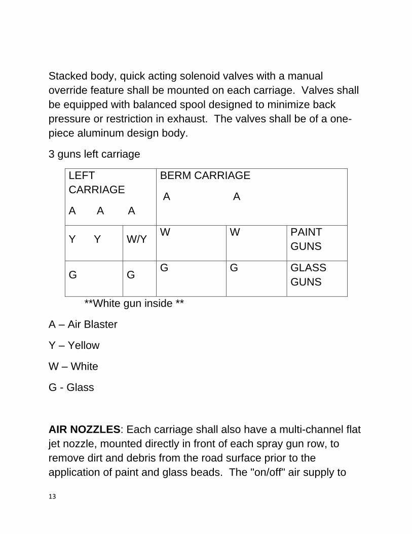
Stacked body, quick acting solenoid valves with a manual
override feature shall be mounted on each carriage. Valves shall
be equipped with balanced spool designed to minimize back
pressure or restriction in exhaust. The valves shall be of a one-
piece aluminum design body.
3 guns left carriage
LEFT
CARRIAGE
A A A
BERM CARRIAGE
A A
Y Y W/Y W W PAINT
GUNS
G G G G GLASS
GUNS
**White gun inside **
A – Air Blaster
Y – Yellow
W – White
G - Glass
AIR NOZZLES: Each carriage shall also have a multi-channel flat
jet nozzle, mounted directly in front of each spray gun row, to
remove dirt and debris from the road surface prior to the
application of paint and glass beads. The "on/off" air supply to
14
these nozzles shall be controlled by means of a lighted rocker
switch, green (on) amber (off) located on the operator control
center. Each air nozzle shall have a manual adjustment air flow
control.
AIR COMPRESSOR: The air compressor shall be a Boss DUS at
250 of free air per minute at 100 PSI. The air system shall be
designed to meet and sustain this specification under all normal
conditions.
All containers shall be ASME approved for 110 PSI working
pressure. All necessary safety valves, piping and fittings shall be
included.
The compressor engine shall be diesel powered, liquid-cooled,
four-cycle, four-cylinder, overhead valve construction, heavy duty
industrial type. It shall include as standard equipment: a fin-tube
type radiator, lubricating oil filter, 12-volt electrical system,
pushbutton starting, and a recommended air filter to be shared
with the compressor air intake. The air compressor engine and
chassis engine shall have a common fuel tank.
A heavy duty, high capacity filter/dryer Schmidt air dryer, capable
of passing all air from the compressor, shall be installed in the air
line.
An electric cooling fan shall be installed into the main airline to
remove heat from the compressed air.
15
A common skid base shall be provided under the engine and
compressor so they may be handled and mounted as a package
unit. The compressor shall be mounted to the platform
longitudinal members. A complete cover with hinged or sliding
access panels shall be supplied for weather protection.
The operating control panel shall be located at the end of the
compressor unit and unit mounted so that it is at the curbside of
the vehicle and include, in addition to operating controls, gauges
showing oil and air pressures, water temperature, voltmeter and
an electric hour meter.
The unit shall be furnished with the following accessory items as a
standard part of the package: hour meter, oil level gauge,
automatic moisture trap for controls, automatic blowdown valve,
minimum pressure valve and a hydraulic pump.
HYDRAULIC SUPPLY: Hydraulic power for the controlling the
outrigger, pointer and paint agitators, shall be from a gear type
hydraulic pump, direct driven by the air compressor engine (no
belts allowed).
Hydraulic tank shall have a long, vertical sight glass tank level
installed to prevent over-filling of hydraulic fluid.
LASER GUIDANCE SYSTEM:
There shall be supplied a GL-3000-P Laser System using an
ultrahigh visibility green laser to establish visual line control for the
paint striping machine. The operator adjusts the laser spot to the
desired reference point on the road via a remote-control panel
located in the cab of the truck.
16
The control shall have a three-function switch for:
1. Laser on Steady mode. 2. Laser on Blinking mode. 3. Laser Off.
There shall be a corresponding green light located on the laser
status panel indicating the laser status:
4. Light on Steady mode. 5. Light Blinking mode. 6. No Light (Off).
To position the laser spot to the desired location; i.e., center line,
road edge, bike lane, etc., the operator shall push the proper
buttons for the direction that he/she wants the laser spot to move
in; left, right, forward, back, and the laser tracks simultaneously.
The system shall have an automatic shutdown feature designed
to minimize power consumption. All functions shall shut off after
the laser function mode has been in the OFF position for two
hours.
The laser, all optics, mechanical mechanisms, and electronics
shall be in a rugged, weatherproof housing that is typically
mounted to the roof of the truck. This permanent installation shall
eliminate the need to remove the laser at the end of the day. Two
cables shall run from the laser housing, one for 12V DC power,
the other for system control in the cab.
Specifications -
Laser - 532mm Class IIIA
17
Power - 12V DC 4.0 amps/hour (Max Operating)
Power/Control Cable Length - Approximately 20 Feet (from laser
box) to DB15 Connector for Operating Temperature - +36° -
+120° F.
Control Box
Laser Box – Approximately, 6-1/8 H x 6-1/2 W x 12 L Inches.
Shipping Weight - 25 Lbs. - Approximate
Secondary: HYDRAULIC POINTER SYSTEM
A front mount adjustable pointer guide shall be provided. The
guide shall be constructed using a trailer ball and coupling type
system.
The pointer shall have a "main" pivot point located near the center
of the bumper. To this pivot shall be fixed the "main guide arm".
The "main guide arm" will be able to swing out for either edge line
or centerline control. A second pivot point will be located at both
outer bumper point locations. This pivot point will offer support for
the "bracing arm". The "bracing arm" shall swing out and support
the "main guide arm" at approximately its mid-point.
The signboard shall have a minimum of 25 hooded, sealed beam
amber LED lamps, with a dimension of approximately 48” by 96”.
It shall be 12-volt with solid state circuitry and a minimum flash
rate of 30 FPM.
The structural frame shall be at least 3” by 2”by 11-gauge
rectangular tubing. The board shall be mounted so when in the
raised position, the highest point is under 12 feet from the ground.
18
For support, four mounting points shall be supplied, two to the
rear of the platform and two on top of the bumper.
NIGHT LIGHTING SYSTEM:
Eight (8) LED floodlights shall be provided on the unit for night
time striping operations. Two (2) lights shall be mounted on the
rear deck area and two (2) lights shall be mounted behind the
carriages, illuminating the guns. The other four (4) lights shall be
mounted around the unit. This system shall include all necessary
wiring and switches.
CONTROL CENTER:
An all-aluminum control center shall be provided. This shall
consist of an integral sheet metal covered framework providing
space for electrical controls, spray equipment connections, heater
thermostat control, and any other auxiliary parts required by the
spray equipment.
The control center shall be mounted in an inclined position so that
it can be observed from either operator's position. This control
center shall have mounted on it, all the necessary regulators,
gauges, valves, switches, and indicators required for operation of
the striping equipment. All parts shall be of the panel type and
located behind the panel if possible. An easily removable back
plate with four (4) recessed latches shall allow access to the
interior for service. Both a 125 PSI safety valve and a
condensate drain shall be located on the panel air manifold. All
the gauges shall be of the liquid-filled type. All control center
switches shall be lighted rocker or push-button type.
19
The spray equipment shall be electrically controlled by means of
toggle switches and solenoid valves. The switches shall be in two
(2) separate control panels within easy reach of the rear
equipment operators. The switch sections shall also house
additional switches and indicator lights for the skipline mechanism
control.
Each control panel shall be located within a non-metallic
enclosure with a clear hinged and latched cover. Each enclosure
shall be mounted to the canopy railing and friction hinged to “flip”
out of the way when necessary.
All line pattern combinations, skipline mechanism actuation, and
skipline mechanism reset shall be controlled by toggle switches.
Pre-selected combinations shall be obtained by activating only on
switch that also simultaneously actuates or resets the skipline
mechanism. One (1) toggle switch shall be an "OFF" switch
connected in such a way that when activated, it will turn off and
cancel any of the above selected patterns, as well as
automatically reset the skipline mechanism to a ready position.
Provision shall be made so that any glass sphere guns may be
controlled from the same system for simultaneous spray gun and
glass gun operation.
The entire switch assembly shall be removable for servicing and
attached by a pin connector.
All electrical wiring shall be enclosed in conduit type protective
case. Any wires passing through the deck shall have grommets
around them.
All electrical controls shall be 12-volt power only.
20
All electrical wiring shall terminate in the operator control center.
A master relay switch independent of the truck ignition switch
shall be installed in a convenient location in the truck cab console
box. All electrical power operation of the painting equipment shall
be wired through this relay, before the circuit breakers, in such a
manner that when the master relay switch is off, all electrical
power from the truck to accessory equipment is off.
All electrical controls shall be 12-volt DC with circuits protected by
manual reset circuit breakers mounted in the console or other
readily accessible area. All electrical wiring shall be enclosed in a
conduit type protective case (or equal) and protected by
grommets through the deck, frame members or similar structures.
All wiring shall be color coded and numbered.
Paint spray gun indicator lights shall be provided on the chassis
cab dash.
INTERCOM SYSTEM (WIRELESS):
A David Clark Model 9900 wireless intercommunication system
shall be furnished to provide a means of vocal communication
between the driver of the vehicle and the operators of the striping
equipment. This system shall provide open communications for all
operator stations.
Two (2) under helmet headsets for the rear operators and three
(3) single ear headset for the front cab operator, and other follow
truck personnel shall be provided. The headsets shall be
equipped with noise cancelling microphone and
on/off/microphone controls for hands free communication
21
SKIPTIMER SYSTEM
It is the stated intent of this specification to describe a highly
reliable, easy to use, simple to install, compact skip-setting
mechanism that requires little or no maintenance and no clutches,
cams, gears, bearings or devices that must be adjusted while at
rest.
The skip timer control boxes shall use mid-sized IP67 rated toggle
switches and shall use sealed push-buttons for menu navigation.
The skip timer control box shall have a full color, 4.3” screen. The color menu system shall provide an animated preview of skip timer patterns, reflecting current settings and switch positions and shall provide guided calibration processes for distance and pump calibrations. The color menu system shall have a descriptive information system to provide the operator with information about errors, warnings, and skip timer operation. There shall be a switch test menu, for infield diagnosis of switch failure, incorporated into the color menu system.
The skip timer system shall communicate using CAN bus serial
communications protocol. It shall have an operating temperature
range from 33°F to 140°F and a storage temperature range of
10°F to 160°F.
The skip timer output boxes shall directly drive all loads (air
dusters, material guns, bead guns, doubledrop bead guns, etc.),
and shall have drive current ratings of five (5) amps per channel.
All outputs shall be solid state. To simplify diagnostics, the skip
timer output boxes shall have driver indicator LEDs for all driver
outputs.
22
The skip timer shall accept motion signals from a magnet wrapped driveline collar. All motion signal sources will maintain a 0.1’ resolution during normal road marking operations. The skip timer system software shall be field upgradeable via USB drive. The skip timer system hardware shall be field upgradeable using hub expansions ports for adding more driver output boxes, sensor input boxes, or data logging equipment.
The skip timer shall separately track skip and solid distance
painted per gun, into internal, nonvolatile counters.
Remote -Control hand- held option on SC-12 skip timer system to
be include.
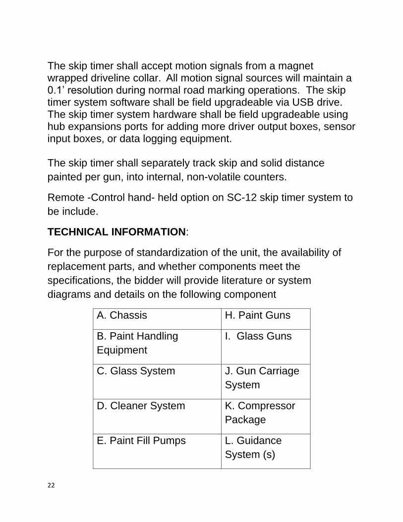
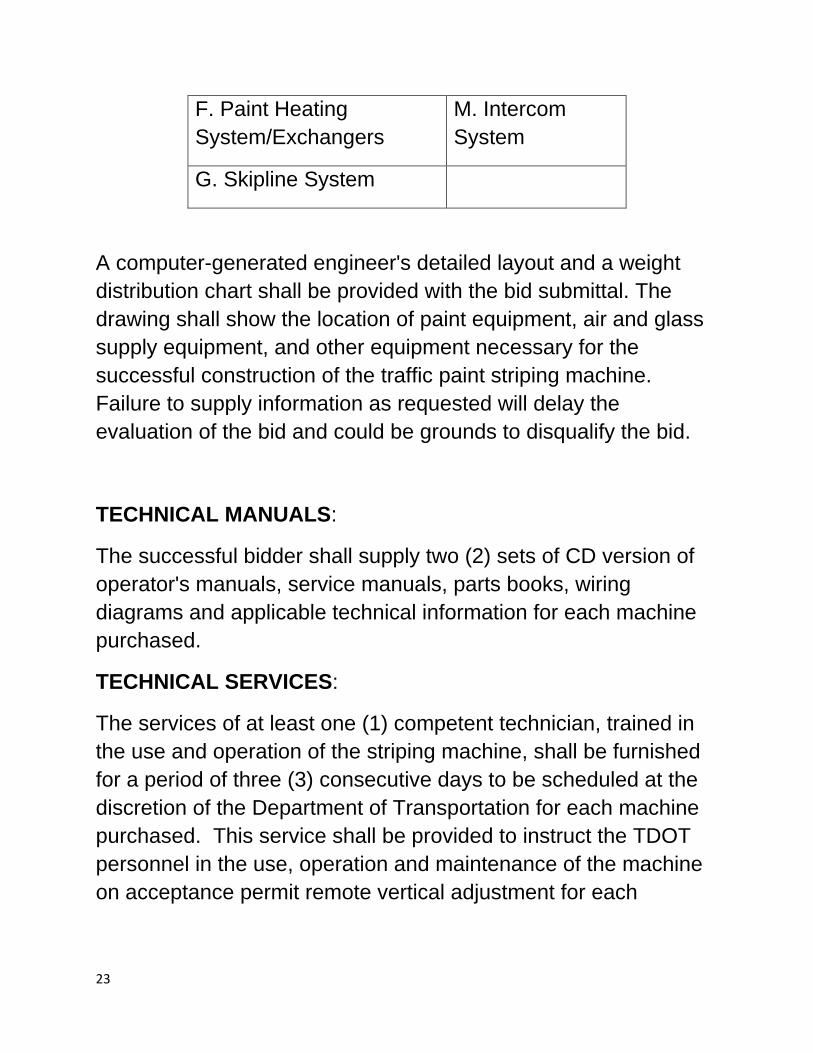
TECHNICAL INFORMATION:
For the purpose of standardization of the unit, the availability of
replacement parts, and whether components meet the
specifications, the bidder will provide literature or system
diagrams and details on the following component
A. Chassis H. Paint Guns
B. Paint Handling
Equipment
I. Glass Guns
C. Glass System J. Gun Carriage
System
D. Cleaner System K. Compressor
Package
E. Paint Fill Pumps L. Guidance
System (s)
23
F. Paint Heating
System/Exchangers
M. Intercom
System
G. Skipline System
A computer-generated engineer's detailed layout and a weight
distribution chart shall be provided with the bid submittal. The
drawing shall show the location of paint equipment, air and glass
supply equipment, and other equipment necessary for the
successful construction of the traffic paint striping machine.
Failure to supply information as requested will delay the
evaluation of the bid and could be grounds to disqualify the bid.
TECHNICAL MANUALS:
The successful bidder shall supply two (2) sets of CD version of
operator's manuals, service manuals, parts books, wiring
diagrams and applicable technical information for each machine
purchased.
TECHNICAL SERVICES:
The services of at least one (1) competent technician, trained in
the use and operation of the striping machine, shall be furnished
for a period of three (3) consecutive days to be scheduled at the
discretion of the Department of Transportation for each machine
purchased. This service shall be provided to instruct the TDOT
personnel in the use, operation and maintenance of the machine
on acceptance permit remote vertical adjustment for each
24
individual gun to change line width anywhere from 4“ to 8”. The
controls shall be mounted at the operator’s stations.


![Tank Specificationspetanks.com/data/chemicalfeedstations[1].pdfTank Specifications Chemical Feed Stations *The pump shelf on the 200 to 330 gallon size are two corner triangular shaped](https://img.pdfslide.net/doc/110x75/5ac0ab9b7f8b9a433f8c00f7/tank-s-1pdftank-specifications-chemical-feed-stations-the-pump-shelf-on-the-200.jpg)