Embed Size (px)
Citation preview
Specifications
M Series
WalkieStacker
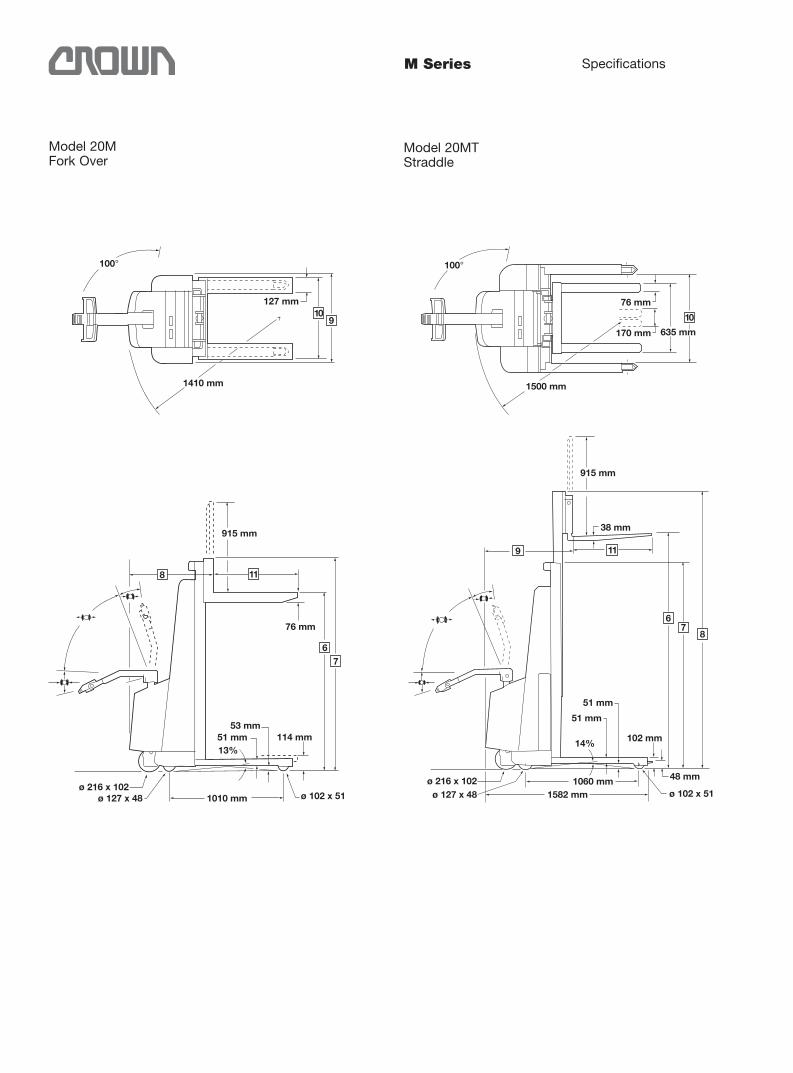
100°
1410 mm
127 mm
9
915 mm
76 mm
53 mm51 mm 114 mm13%
1010 mmø 127 x 48ø 216 x 102
8
67
915 mm
38 mm
48 mm
51 mm
102 mm14%
ø 102 x 51ø 216 x 102
ø 127 x 481060 mm
1582 mm
1500 mm
76 mm
170 mm
100°
10 10
9 11
67
8
51 mm
635 mm
11
ø 102 x 51
M Series Specifications
Model 20MFork Over
Model 20MTStraddle
M Series Specifications
BRight Angle Aisles
A
Equal In
ters
ectin
g Aisl
es
PalletLength
PalletWidth
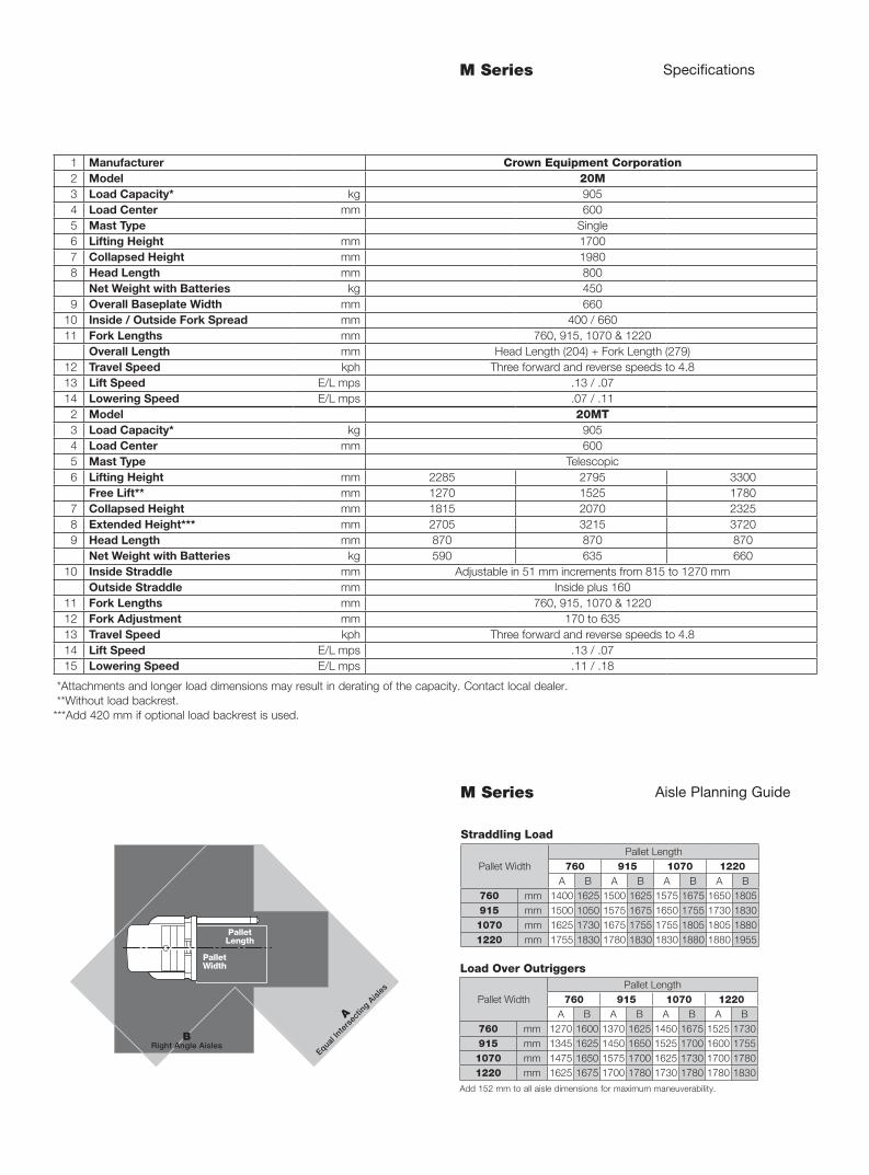
M Series Aisle Planning Guide
1 Manufacturer Crown Equipment Corporation2 Model 20M3 Load Capacity* kg 9054 Load Center mm 6005 Mast Type Single6 Lifting Height mm 17007 Collapsed Height mm 19808 Head Length mm 800
Net Weight with Batteries kg 4509 Overall Baseplate Width mm 660
10 Inside / Outside Fork Spread mm 400 / 66011 Fork Lengths mm 760, 915, 1070 & 1220
Overall Length mm Head Length (204) + Fork Length (279)12 Travel Speed kph Three forward and reverse speeds to 4.813 Lift Speed E/L mps .13 / .0714 Lowering Speed E/L mps .07 / .112 Model 20MT3 Load Capacity* kg 9054 Load Center mm 6005 Mast Type Telescopic6 Lifting Height mm 2285 2795 3300
Free Lift** mm 1270 1525 17807 Collapsed Height mm 1815 2070 23258 Extended Height*** mm 2705 3215 37209 Head Length mm 870 870 870
Net Weight with Batteries kg 590 635 66010 Inside Straddle mm Adjustable in 51 mm increments from 815 to 1270 mm
Outside Straddle mm Inside plus 16011 Fork Lengths mm 760, 915, 1070 & 122012 Fork Adjustment mm 170 to 63513 Travel Speed kph Three forward and reverse speeds to 4.814 Lift Speed E/L mps .13 / .0715 Lowering Speed E/L mps .11 / .18
*Attachments and longer load dimensions may result in derating of the capacity. Contact local dealer. **Without load backrest.***Add 420 mm if optional load backrest is used.
Pallet WidthPallet Length
760 915 1070 1220A B A B A B A B
760 mm 1400 1625 1500 1625 1575 1675 1650 1805915 mm 1500 1050 1575 1675 1650 1755 1730 18301070 mm 1625 1730 1675 1755 1755 1805 1805 18801220 mm 1755 1830 1780 1830 1830 1880 1880 1955
Pallet WidthPallet Length
760 915 1070 1220A B A B A B A B
760 mm 1270 1600 1370 1625 1450 1675 1525 1730915 mm 1345 1625 1450 1650 1525 1700 1600 17551070 mm 1475 1650 1575 1700 1625 1730 1700 17801220 mm 1625 1675 1700 1780 1730 1780 1780 1830
Straddling Load
Load Over Outriggers
Add 152 mm to all aisle dimensions for maximum maneuverability.
M Series Technical Information
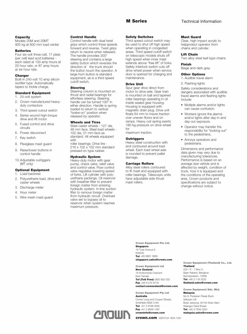
Capacity Models 20M and 20MT 905 kg at 600 mm load center
Batteries Four six-volt three-cell, 17 plate (per cell) lead acid batteries - each rated at 100 amp hours at 20 hour rate, or 87 amp hours at six hour rate.
Charger Built-in 240-volt 10 amp silicon rectifier type. Automatically tapers to trickle charge.
Standard Equipment 1. 24-volt system
2. Crown manufactured heavy- duty con tactors
3. Third speed cutout switch
4. Series wound high-torque drive and lift motor
5. Fused control and drive circuits
6. Power disconnect
7. Key switch
8. Plexiglass mast guard
9. Raise/lower buttons in control handle
10. Adjustable outriggers (MT only)
Optional Equipment 1. Load backrest
2. Polyurethane load, drive and caster wheels
3. Discharge meter
4. Hour meter
5. Wire mesh mast guard
Control Handle Control handle with dual twist grips which control three speeds forward and reverse. Twist grips return to neutral when released. The handle provides 200° steering and contains a large safety button which reverses the direction of the truck should the button touch the operator. A large horn button is standard equipment, as is a third speed cutoff switch.
Steering Steering column is mounted on thrust and radial bearings for effortless steering. Steering handle can be turned 100° in either direction. Handle is spring loaded to return to vertical “brake-on” position when released by operator.
Wheels and Tires Steel caster wheels - 127 dia, 48 mm face. Steel load wheels - 102 dia, 51 mm face as standard. All wheels equipped with roller bearings. Drive tire - 216 x 102 x 102 mm standard pressed-on type rubber.
Hydraulic System Heavy-duty motor with gear pump, check valve, relief valve and control valve. Flow control valve regulates lowering speed of forks. Lift cylinder with poly-urethane packings. Oil reservoir with breather-filter to prevent foreign matter from entering hydraulic system. In-line suction filter to remove foreign matter from hydraulic circuit. Overload valve set to bypass oil to reservoir when system reaches maximum pressure.
Safety Switches Third speed cutout switch may be used to shut off high speed when operating in congested areas. Third speed cutoff switch on telescopic models shuts off high speed when inner mast extends above “free lift” of forks. Safety interlock switch cuts off drive wheel power when service door is opened for charging and maintenance.
Drive Unit Spur gear drive direct from motor to drive axle. Gear train is mounted on ball and tapered roller bearings operating in oil inside sealed gear housing. Housing is equipped with magnetic drain plug. Drive unit floats 64 mm to insure traction over uneven floors and on ramps. Heavy coil spring exerts 180 kg pressure on drive wheel for maximum traction.
Outriggers Heavy steel construction with end contoured around load wheel. Each load wheel axle is rounded to prevent pallet damage.
Carriage Rollers Alloy steel rollers contoured to fit mast and equipped with roller bearings. Telescopic units have adjustable side-thrust mast rollers.
Mast Guard Clear, high impact acrylic to helpprotect operator from chains and cylinder.
Lift Chain Two alloy steel leaf-type chains
Finish Beige and dark gray
Other Options 1. Audible travel alarm
2. Flashing lights
Safety considerations and dangers associated with audible travel alarms and flashing lights include:
• Multiple alarms and/or lights can cause confusion.
• Workers ignore the alarms and/or lights after day-in and day-out exposure.
• Operator may transfer the responsibility for “looking out” to the pedestrians.
• Annoys operators and pedestrians.
Dimensions and performance data given may vary due to manufacturing tolerances. Performance is based on an average size vehicle and is affected by weight, condition of truck, how it is equipped and the conditions of the operating area. Crown products and specifications are subject to change without notice.
crown.com
Crown Equipment Pty LtdAustraliaCorner Long and Cooper Streets,Smithfield NSW [email protected]
Crown Equipment LtdNew Zealand18 Andromeda Crescent East TamakiTel (Toll Free)[email protected]
Crown Equipment Pte Ltd.Singapore15 Tuas Avenue 8 [email protected]
+61 2 8788 0000+61 2 9609 1497
0800 802 002+64 9 274 9718
+65 6861 3669
Crown Equipment Sdn. Bhd.MalaysiaNo 9, Persiaran Pasak Bumi Seksyen U8 Bukit Jelutong, 40150 Shah Alam Selangor Darul [email protected]
+60 3-7845 2291
Crown Equipment (Thailand) Co., Ltd.Thailand222 / 6 - 7 Moo 5, Baan Rakard, Bangboa Samutprakarn, [email protected]
+66 2-118 3222
ASF0104 1604.1331