Embed Size (px)
Citation preview
1
ENGINE
MODEL PERKINS 1204E
TypeWater cooled, 4 cycle Diesel, 4-Cylindersin line, direct injection, turbocharged,charged air cooled and low emission
Rated flywheel horse power
SAEJ1995 (gross) 137 HP (102.2 kW) / 2,050 rpm
J1349 (net) 128 HP (96 kW) / 2,050 rpm
DIN6271/1 (gross) 139 PS (102.2 kW) / 2,050 rpm
6271/1 (net) 130 PS (96 kW) / 2,050 rpm
Max. torque 57.1 kgf.m (413 lbf.ft) / 1,500 rpm
Bore x stroke 105 x 127 mm (4.13” x 5.0”)
Piston displacement 4,400 cc (268.5 in3)
Batteries 2 x 12 V x 100AH
Starting motor 24 V- 4.5 kW
Alternator 24 V- 80 Amp
* This engine meets the EPA (Tier 4 interim) / EU (Stage III-B) Emission regulation.
HYDRAULIC SYSTEM
MAIN PUMPType Variable displacement axial piston pumps
Max. flow 2 x 160 ℓ/min (44.4 US gpm / 37.0 UK gpm)
Sub-pump for pilot circuit Gear pump
Cross-sensing and fuel saving pump system
HYDRAULIC MOTORS
TravelTwo-speed axial piston motorwith brake valve and parking brake
Swing Axial piston motor with automatic brake
RELIEF VALVE SETTINGImplement circuits 350 kgf/cm2 (4,980 psi)
Travel 350 kgf/cm2 (4,980 psi)
Power boost (boom, arm, bucket) 380 kgf/cm2 (5,410 psi)
Swing circuit 285 kgf/cm2 (4,050 psi)
Pilot circuit 40 kgf/cm2 (570 psi)
Service valve Installed
HYDRAULIC CYLINDERS
No. of cylinder- bore x stroke
Boom: 2-115 x 1,090 mm (4.5” x 42.9”)
Arm: 1-120 x 1,355 mm (4.7” x 53.3”)
Bucket: 1-110 x 995 mm (4.3” x 39.2”)
Blade: 2-110 x 320 mm (4.3” x 12.6”)
2PC-boom
1st: 2-115 x 960 mm (4.5” x 37.8”)
2nd: 1-160 x 650 mm (6.3” x 25.6”)
DRIVES & BRAKES
Drive method Fully hydrostatic type
Drive motor Axial piston motor, in-shoe design
Reduction system Planetary reduction gear
Max. drawbar pull 17,000 kgf (37,500 lbf )
Max. travel speed (high) / (low) 5 km/h (3.1 mph) / 3.2 km/h (2.0 mph)
Gradeability 30° (58 %)
Parking brake Multi wet disc
CONTROLPilot pressure operated joysticks and pedals with detachable lever provide almost effortless and fatigueless operation.
Pilot controlTwo joysticks with one safety lever (LH): Swing and arm(RH): Boom and bucket (ISO)
Traveling and steering Two levers with pedals
Engine throttle Electric, Dial type
SWING SYSTEM
Swing motor Two fixed displacement axial piston motor
Swing reduction Planetary gear reduction
Swing bearing lubrication Grease-bathed
Swing brake Multi wet disc
Swing speed 11.2 rpm
COOLANT & LUBRICANT CAPACITY
Refilling liter US gal UK gal
Fuel tank 270 71.3 59.4
Engine coolant 15.5 4.1 3.4
Engine oil 10.5 2.8 2.3
Swing device-gear oil 5.0 1.3 1.1
Final drive (each)-gear oil 5.8 1.5 1.3
Hydraulic system (including tank) 270 71.3 59.4
Hydraulic tank 160 42.3 35.2
UNDERCARRIAGEThe X-leg type center frame is integrally welded with reinforced box-section trackframes. The undercarriage includes lubricated rollers, idlers, track adjusters with shockabsorbing springs and sprockets, and a track chain with double or triple grouser shoes.
Center frame X - leg type
Track frame Pentagonal box type
No. of shoes on each side 51
No. of carrier rollers on each side 2
No. of track rollers on each side 7
No. of rail guards on each side 2
OPERATING WEIGHT (APPROXIMATE)Operating weight, including 5,100 mm (16’ 9”) boom, 2,600 mm (8’ 6”) arm, SAE heaped 0.76 m3 (0.99 yd3) bucket, lubricant, coolant, full fuel tank, full hydraulic tank and all standard equipments.
MAJOR COMPONENT WEIGHTUpperstructure 4,980 kg (10,980 lb)
5.1 m (16’ 9”) mono boom (with arm cylinder) 1,250 kg (2,760 lb)
Hydraulic adjustable boom (with arm cylinder) 1,780 kg (3,920 lb)
OPERATING WEIGHTShoes Operating weight Ground pressure
Type Width mm (in) kg (lb) kgf/cm2 (psi)
Triplegrouser
500 (20”)
R180LC-9A 18,350 (40,450) 0.51 (7.25)
R180LCD-9A 19,350 (42,660) 0.53 (7.54)
R180NLC-9A 18,260 (40,260) 0.50 (7.11)
600 (24”)
R180LC-9A 18,600 (41,010) 0.43 (6.11)
R180LCD-9A 19,600 (43,210) 0.45 (6.40)
R180NLC-9A 18,510 (40,810) 0.43 (6.11)
700 (28”)R180LC-9A 18,850 (41,560) 0.37 (5.26)
R180LCD-9A 19,850 (43,760) 0.39 (5.55)
800 (32”)R180LC-9A 19,100 (42,110) 0.33 (4.69)
R180LCD-9A 20,100 (44,310) 0.35 (4.98)
Specifications R180LC-9A
2
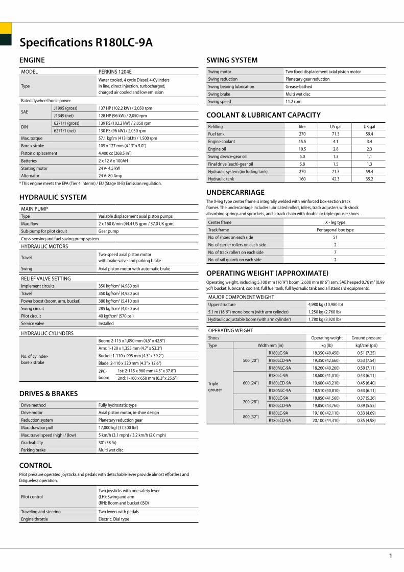
BUCKETS R180LC-9AAll buckets are welded with high-strength steel.
SAE heaped m3 (yd3)
ATTACHMENT R180LC-9ABooms and arms are welded, a low-stress, full-box section design. 5.1 m (16’ 9”) boom & 5.1 m (16’ 9”) hydraulic adjustable boom and 2.20 m (7’ 3”); 2.60 m (8’ 6”) & 3.10 m (10’ 2”) arms are available.
Note: Boom weight includes arm cylinder, piping and pin Arm weight includes bucket cylinder, linkage and pin
DIGGING FORCE R180LC-9A
Capacity m3 (yd3)
SAE heaped CECE heaped
Width mm (in)
Without side cutters
With side cutters
Weight kg (lb)
Recommendation m (ft.in)
5.1 (16’ 9”) Mono Boom
Heavy-duty bucket Applicable for materials with density of 2,000 kg/m3 (3,370 lb/yd3) or less
Applicable for materials with density of 1,600 kg/m3 (2,700 lb/yd3) or less
Applicable for materials with density of 1,100 kg/m3 (1,850 lb/yd3) or less
0.39 (0.51)
0.50 (0.65)
0.64 (0.84)
0.76 (0.99)
0.89 (1.16)
1.05 (1.37)
0.69 (0.90)
0.34 (0.44)
0.44 (0.58)
0.55 (0.72)
0.65 (0.85)
0.77 (1.01)
0.90 (1.18)
0.62 (0.81)
620 (24.4)
760 (29.9)
920 (36.2)
1,060 (41.7)
1,220 (48.0)
1,400 (55.1)
990 (39.0)
740 (29.1)
880 (34.6)
1,040 (40.9)
1,180 (46.5)1,340 (52.8)
1,520 (59.8)
-
410 (900)
470 (1,040)
510 (1,120)
570 (1,260)
610 (1,340)
680 (1,500)
700 (1,540)
5.1 (16’ 9”) Hydraulic Adjustable Boom
2.6 (8’ 6”) Arm2.2 (7’ 3”) Arm 3.1 (10’ 2”) Arm 2.6 (8’ 6”) Arm 2.2 (7’ 3”) Arm
mm (ft.in)
kg (lb)
mm (ft.in)
kg (lb)
2,200 (7’ 3”)
750 (1,560)
107.9 [117.2]
11,000 [11,940]
24,250 [26,330]
123.6 [134.2]
12,600 [13,680]
27,780 [30,160]
87.2 [94.7]
8,890 [9,650]
19,600 [21,280]
91.0 [98.8]
9,280 [10,080]
20,460 [22,210]
107.9 [117.2]
11,000 [11,940]
24,250 [26,330]
123.6 [134.2]
12,600 [13,680]
27,780 [30,160]
77.3 [83.9]
7,880 [8,560]
17,370 [18,860]
80.3 [87.2]
8,190[8,890]
18,060 [19,600]
107.9 [117.2]
11,000 [11,940]
24,250 [26,330]
123.6 [134.2]
12,600 [13,680]
27,780 [30,160]
69.0 [74.9]
7,030 [7,630]
15,500 [16,830]
71.4 [77.5]
7,280 [7,900]
16,050 [17,430]
2,600 (8’ 6”)
810 (1,790)
3,100 (10’ 2”)
890 (1,960)
5,100 (16’ 9”)
1,250 (2,760)
SAE
kN
kgf
lbf
ISO
kN
kgf
lbf
SAE
kN
kgf
lbf
ISO
kN
kgf
lbf
0.39 (0.51) 0.50 (0.65) 0.64 (0.84) 0.69 (0.90)0.76 (0.99) 0.89 (1.16) 1.05 (1.37)
BoomLength
Weight
Arm
Bucketdigging
force
Armcrowdforce
[ ]:PowerBoost
RemarksLength
Weight
3
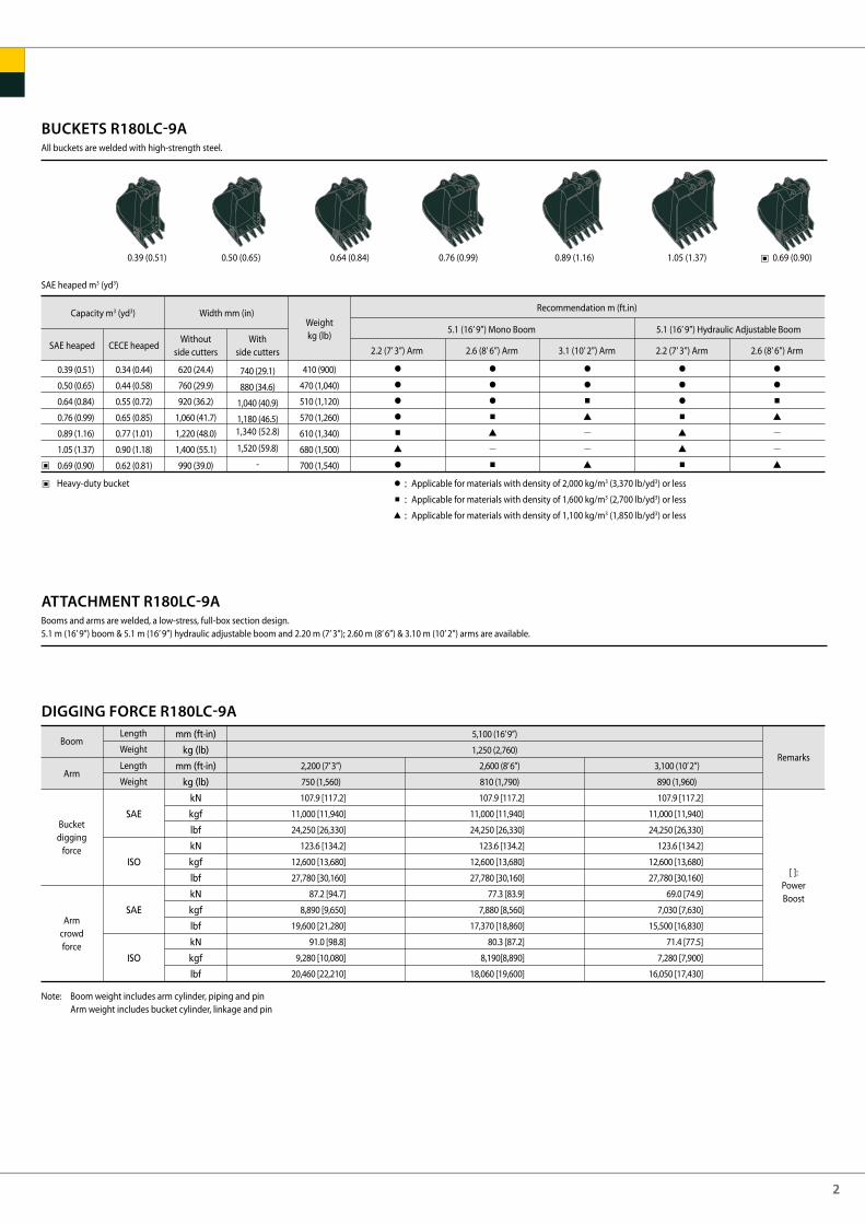
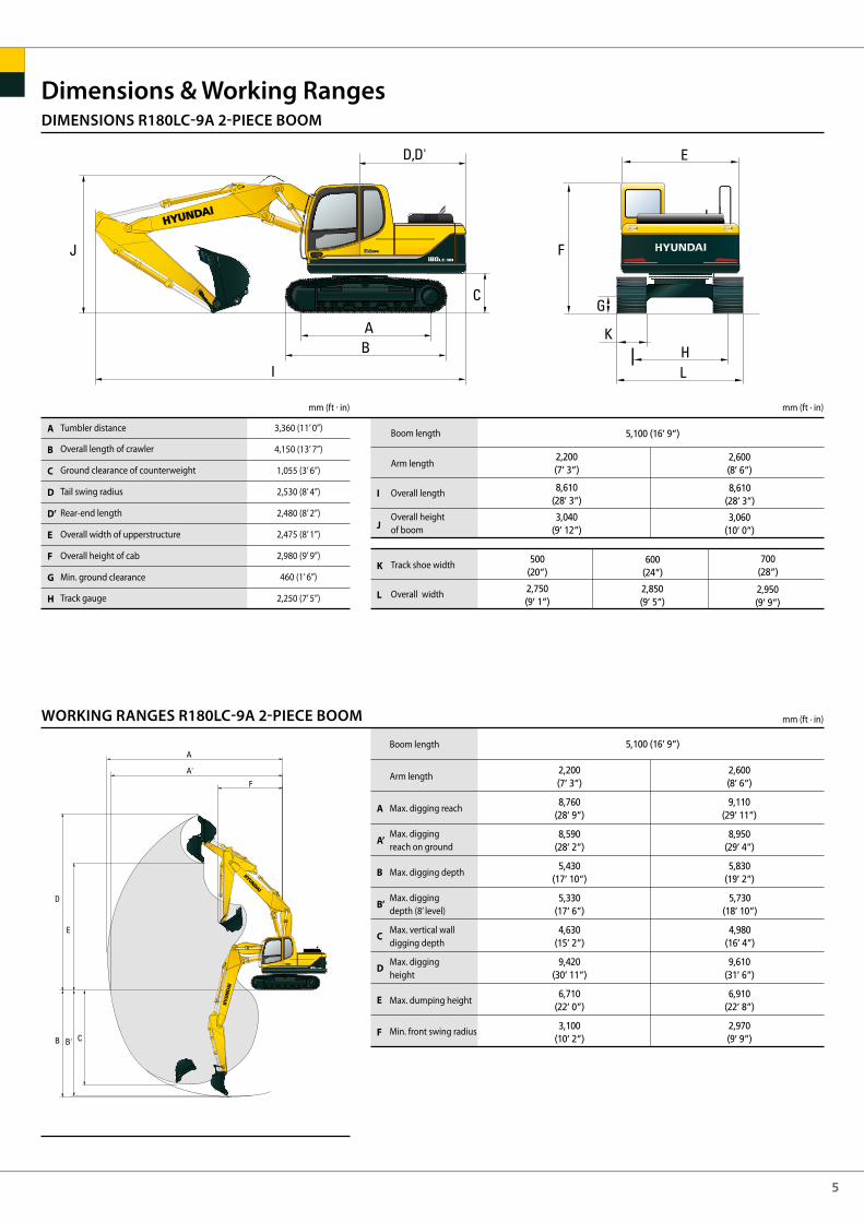
DIMENSIONS R180LC-9A
WORKING RANGES R180LC-9A
Dimensions & Working Ranges
mm (ft · in)mm (ft . in)
mm (ft · in)
Boom length
Arm length
Overall length
Overall heightof boom
Track shoe width
Overall width
Boom length
Arm length
Max. digging reach
Max. diggingreach on ground
Max. digging depth
Max. diggingdepth (8’ level)
Max. vertical walldigging depth
Max. digging height
Max. dumping height
Min. front swing radius
Tumbler distance
Overall length of crawler
Ground clearance of counterweight
Tail swing radius
Rear-end length
Overall width of upperstructure
Overall height of cab
Min. ground clearance
Track gauge
A
B
C
D
D’
E
F
G
H
I
J
K
L
A
A’
B
B’
C
D
E
F
3,360 (11’ 0”)
4,150 (13’ 7”)
1,055 (3’ 6”)
2,530 (8’ 4”)
2,480 (8’ 2”)
2,475 (8’ 1”)
2,980 (9’ 9”)
460 (1’ 6”)
2,250 (7’ 5”)
2,200(7’ 3”)
8,690(28’ 6”)
8,530(27’ 12”)
5,660(18’ 7”)
5,430(17’ 10”)
5,120(16’ 10”)
8,750(28’ 8”)
6,110(20’ 1”)
3,180(10’ 5”)
2,600(8’ 6”)
9,020(29’ 7”)
8,860(29’ 1”)
6,060(19’ 11”)
5,850(19’ 2”)
5,380(17’ 8”)
8,840(29’ 0”)
6,220(20’ 5”)
3,170(10’ 5”)
3,100(10’ 2”)
9,450(31’ 0”)
9,300(30’ 6”)
6,560(21’ 6”)
6,370(20’ 11”)
5,710(18’ 9”)
8,980(29’ 6”)
6,390(21’ 0”)
3,170(10’ 5”)
2,200(7’ 3”)
8,660(28'5'')
500(20”)
3,010(9’ 11”)
2,750(9’ 1”)
2,600(8’ 6”)
8,650(28’ 5”)
600(24”)
2,990(9’ 10”)
2,850(9’ 5”)
3,100(10’ 2”)
8,650(28'5'')
700(28”)
3,150(10’ 4”)
2,950(9’ 9”)
5,100 (16’ 9”)
5,100 (16’ 9”)

4
DIMENSIONS R180NLC-9A
WORKING RANGES R180NLC-9A
Dimensions & Working Ranges
mm (ft · in)mm (ft . in)
mm (ft · in)
Boom length
Arm length
Overall length
Overall heightof boom
Track shoe width
Overall width
Boom length
Arm length
Max. digging reach
Max. diggingreach on ground
Max. digging depth
Max. diggingdepth (8’ level)
Max. vertical walldigging depth
Max. digging height
Max. dumping height
Min. front swing radius
Tumbler distance
Overall length of crawler
Ground clearance of counterweight
Tail swing radius
Rear-end length
Overall width of upperstructure
Overall height of cab
Min. ground clearance
Track gauge
A
B
C
D
D’
E
F
G
H
I
J
K
L
A
A’
B
B’
C
D
E
F
3,360 (11’ 0”)
4,150 (13’ 7”)
1,055 (3’ 6”)
2,530 (8’ 4”)
2,480 (8’ 2”)
2,475 (8’ 1”)
2,980 (9’ 9”)
460 (1’ 6”)
2,000 (6’ 7”)
2,200(7’ 3”)
8,690(28’ 6”)
8,530(27’ 12”)
5,660(18’ 7”)
5,430(17’ 10”)
5,120(16’ 10”)
8,750(28’ 8”)
6,110(20’ 1”)
3,180(10’ 5”)
2,600(8’ 6”)
9,020(29’ 7”)
8,860(29’ 1”)
6,060(19’ 11”)
5,850(19’ 2”)
5,380(17’ 8”)
8,840(29’ 0”)
6,220(20’ 5”)
3,170(10’ 5”)
3,100(10’ 2”)
9,450(31’ 0”)
9,300(30’ 6”)
6,560(21’ 6”)
6,370(20’ 11”)
5,710(18’ 9”)
8,980(29’ 6”)
6,390(21’ 0”)
3,170(10’ 5”)
2,200(7’ 3”)
8,660(28'5'')
500(20”)
3,010(9’ 11”)
2,500(8’ 2”)
2,600(8’ 6”)
8,650(28’ 5”)
600(24”)
2,990(9’ 10”)
2,600(8’ 6”)
3,100(10’ 2”)
8,650(28'5'')
3,150(10’ 4”)
5,100 (16’ 9”)
5,100 (16’ 9”)
5
DIMENSIONS R180LC-9A 2-PIECE BOOM
WORKING RANGES R180LC-9A 2-PIECE BOOM
Dimensions & Working Ranges
mm (ft · in)mm (ft . in)
mm (ft · in)
Boom length
Arm length
Overall length
Overall heightof boom
Track shoe width
Overall width
Boom length
Arm length
Max. digging reach
Max. diggingreach on ground
Max. digging depth
Max. diggingdepth (8’ level)
Max. vertical walldigging depth
Max. digging height
Max. dumping height
Min. front swing radius
Tumbler distance
Overall length of crawler
Ground clearance of counterweight
Tail swing radius
Rear-end length
Overall width of upperstructure
Overall height of cab
Min. ground clearance
Track gauge
A
B
C
D
D’
E
F
G
H
I
J
K
L
A
A’
B
B’
C
D
E
F
3,360 (11’ 0”)
4,150 (13’ 7”)
1,055 (3’ 6”)
2,530 (8’ 4”)
2,480 (8’ 2”)
2,475 (8’ 1”)
2,980 (9’ 9”)
460 (1’ 6”)
2,250 (7’ 5”)
2,200(7’ 3”)
8,760(28’ 9”)
8,590(28’ 2”)
5,430(17’ 10”)
5,330(17’ 6”)
4,630(15’ 2”)
9,420(30’ 11”)
6,710(22’ 0”)
3,100(10’ 2”)
2,600(8’ 6”)
9,110(29’ 11”)
8,950(29’ 4”)
5,830(19’ 2”)
5,730(18’ 10”)
4,980(16’ 4”)
9,610(31’ 6”)
6,910(22’ 8”)
2,970(9’ 9”)
5,100 (16’ 9”)
2,200(7’ 3”)
8,610(28’ 3”)
500(20”)
3,040(9’ 12”)
2,750(9’ 1”)
2,600(8’ 6”)
8,610(28’ 3”)
600(24”)
3,060(10’ 0”)
2,850(9’ 5”)
700(28”)
2,950(9’ 9”)
5,100 (16’ 9”)
6
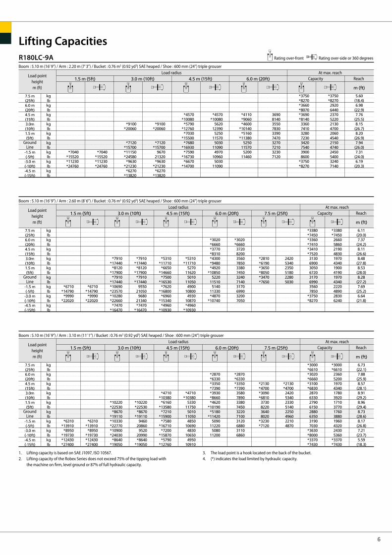
R180LC-9A Rating over-front Rating over-side or 360 degrees
Lifting Capacities
Boom : 5.10 m (16’ 9”) / Arm : 2.20 m (7’ 3”) / Bucket : 0.76 m3 (0.92 yd3) SAE heaped / Shoe : 600 mm (24”) triple grouser
Load pointheightm (ft)
Load radius At max. reachCapacity Reach
GroundLine
Boom : 5.10 m (16’ 9”) / Arm : 2.60 m (8’ 6”) / Bucket : 0.76 m3 (0.92 yd3) SAE heaped / Shoe : 600 mm (24”) triple grouser
Load pointheightm (ft)
Load radius At max. reachCapacity Reach
GroundLine
Boom : 5.10 m (16’ 9”) / Arm : 3.10 m (11’ 1”) / Bucket : 0.76 m3 (0.92 yd3) SAE heaped / Shoe : 600 mm (24”) triple grouser
Load pointheightm (ft)
Load radius At max. reachCapacity Reach
GroundLine
1. Lifting capacity is based on SAE J1097, ISO 10567.2. Lifting capacity of the Robex Series does not exceed 75% of the tipping load with the machine on firm, level ground or 87% of full hydraulic capacity.
3. The load point is a hook located on the back of the bucket.4. (*) indicates the load limited by hydraulic capacity.
7
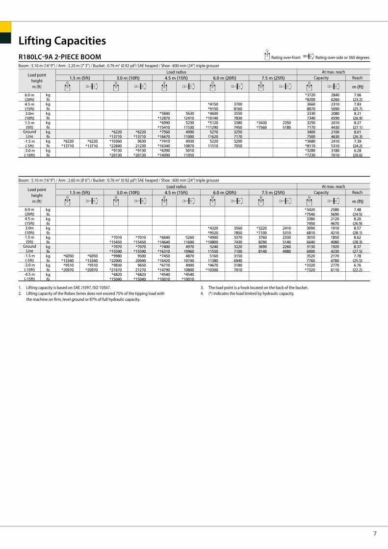
Lifting CapacitiesR180LC-9A 2-PIECE BOOM Rating over-front Rating over-side or 360 degrees
Boom : 5.10 m (16’ 9”) / Arm : 2.20 m (7’ 3”) / Bucket : 0.76 m3 (0.92 yd3) SAE heaped / Shoe : 600 mm (24”) triple grouser
Load pointheightm (ft)
Load radius At max. reachCapacity Reach
GroundLine
Boom : 5.10 m (16’ 9”) / Arm : 2.60 m (8’ 6”) / Bucket : 0.76 m3 (0.92 yd3) SAE heaped / Shoe : 600 mm (24”) triple grouser
Load pointheightm (ft)
Load radius At max. reachCapacity Reach
GroundLine
1. Lifting capacity is based on SAE J1097, ISO 10567.2. Lifting capacity of the Robex Series does not exceed 75% of the tipping load with the machine on firm, level ground or 87% of full hydraulic capacity.
3. The load point is a hook located on the back of the bucket.4. (*) indicates the load limited by hydraulic capacity.
8
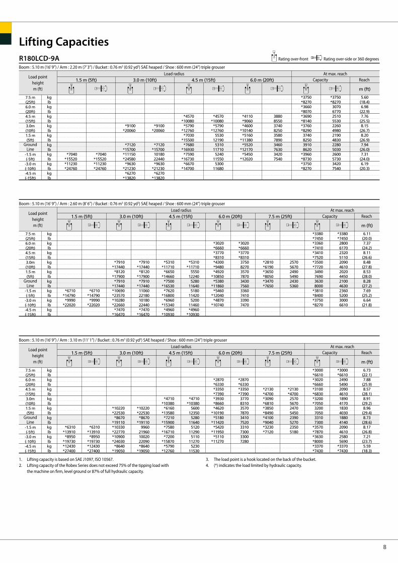
Lifting CapacitiesR180LCD-9A Rating over-front Rating over-side or 360 degrees
Boom : 5.10 m (16’ 9”) / Arm : 2.20 m (7’ 3”) / Bucket : 0.76 m3 (0.92 yd3) SAE heaped / Shoe : 600 mm (24”) triple grouser
Load pointheightm (ft)
Load radius At max. reachCapacity Reach
GroundLine
Boom : 5.10 m (16’ 9”) / Arm : 2.60 m (8’ 6”) / Bucket : 0.76 m3 (0.92 yd3) SAE heaped / Shoe : 600 mm (24”) triple grouser
Load pointheightm (ft)
Load radius At max. reachCapacity Reach
GroundLine
Boom : 5.10 m (16’ 9”) / Arm : 3.10 m (11’ 1”) / Bucket : 0.76 m3 (0.92 yd3) SAE heaped / Shoe : 600 mm (24”) triple grouser
Load pointheightm (ft)
Load radius At max. reachCapacity Reach
GroundLine
1. Lifting capacity is based on SAE J1097, ISO 10567.2. Lifting capacity of the Robex Series does not exceed 75% of the tipping load with the machine on firm, level ground or 87% of full hydraulic capacity.
3. The load point is a hook located on the back of the bucket.4. (*) indicates the load limited by hydraulic capacity.

9
Lifting CapacitiesR180NLC-9A Rating over-front Rating over-side or 360 degrees
Boom : 5.10 m (16’ 9”) / Arm : 2.20 m (7’ 3”) / Bucket : 0.76 m3 (0.92 yd3) SAE heaped / Shoe : 600 mm (24”) triple grouser
Load pointheightm (ft)
Load radius At max. reachCapacity Reach
GroundLine
Boom : 5.10 m (16’ 9”) / Arm : 2.60 m (8’ 6”) / Bucket : 0.76 m3 (0.92 yd3) SAE heaped / Shoe : 600 mm (24”) triple grouser
Load pointheightm (ft)
Load radius At max. reachCapacity Reach
GroundLine
Boom : 5.10 m (16’ 9”) / Arm : 3.10 m (11’ 1”) / Bucket : 0.76 m3 (0.92 yd3) SAE heaped / Shoe : 600 mm (24”) triple grouser
Load pointheightm (ft)
Load radius At max. reachCapacity Reach
GroundLine
1. Lifting capacity is based on SAE J1097, ISO 10567.2. Lifting capacity of the Robex Series does not exceed 75% of the tipping load with the machine on firm, level ground or 87% of full hydraulic capacity.
3. The load point is a hook located on the back of the bucket.4. (*) indicates the load limited by hydraulic capacity.
www.hyundai.eu EN - 2013.12 Rev 0
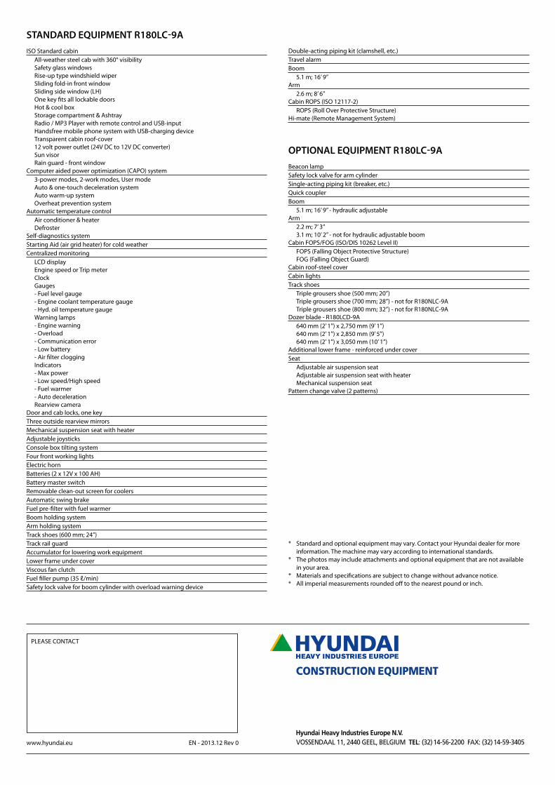
STANDARD EQUIPMENT R180LC-9A
ISO Standard cabinAll-weather steel cab with 360° visibilitySafety glass windowsRise-up type windshield wiperSliding fold-in front windowSliding side window (LH)One key fits all lockable doorsHot & cool boxStorage compartment & AshtrayRadio / MP3 Player with remote control and USB-input Handsfree mobile phone system with USB-charging device Transparent cabin roof-cover12 volt power outlet (24V DC to 12V DC converter)Sun visorRain guard - front window
Computer aided power optimization (CAPO) system3-power modes, 2-work modes, User modeAuto & one-touch deceleration systemAuto warm-up systemOverheat prevention system
Automatic temperature controlAir conditioner & heaterDefroster
Self-diagnostics systemStarting Aid (air grid heater) for cold weatherCentralized monitoring
LCD displayEngine speed or Trip meterClockGauges- Fuel level gauge- Engine coolant temperature gauge- Hyd. oil temperature gaugeWarning lamps- Engine warning- Overload- Communication error- Low battery- Air filter clogging Indicators- Max power- Low speed/High speed- Fuel warmer- Auto decelerationRearview camera
Door and cab locks, one keyThree outside rearview mirrorsMechanical suspension seat with heater Adjustable joysticksConsole box tilting systemFour front working lightsElectric hornBatteries (2 x 12V x 100 AH)Battery master switchRemovable clean-out screen for coolersAutomatic swing brakeFuel pre-filter with fuel warmerBoom holding systemArm holding systemTrack shoes (600 mm; 24”)Track rail guardAccumulator for lowering work equipmentLower frame under coverViscous fan clutchFuel filler pump (35 ℓ/min)Safety lock valve for boom cylinder with overload warning device
Double-acting piping kit (clamshell, etc.)Travel alarmBoom
5.1 m; 16’ 9”Arm
2.6 m; 8’ 6”Cabin ROPS (ISO 12117-2)
ROPS (Roll Over Protective Structure)Hi-mate (Remote Management System)
OPTIONAL EQUIPMENT R180LC-9A
Beacon lampSafety lock valve for arm cylinderSingle-acting piping kit (breaker, etc.)Quick couplerBoom
5.1 m; 16’ 9” - hydraulic adjustableArm
2.2 m; 7’ 3”3.1 m; 10’ 2” - not for hydraulic adjustable boom
Cabin FOPS/FOG (ISO/DIS 10262 Level II)FOPS (Falling Object Protective Structure)FOG (Falling Object Guard)
Cabin roof-steel coverCabin lightsTrack shoes
Triple grousers shoe (500 mm; 20”)Triple grousers shoe (700 mm; 28”) - not for R180NLC-9ATriple grousers shoe (800 mm; 32”) - not for R180NLC-9A
Dozer blade - R180LCD-9A640 mm (2’ 1”) x 2,750 mm (9’ 1”)640 mm (2’ 1”) x 2,850 mm (9’ 5”)640 mm (2’ 1”) x 3,050 mm (10’ 1”)
Additional lower frame - reinforced under coverSeat
Adjustable air suspension seatAdjustable air suspension seat with heaterMechanical suspension seat
Pattern change valve (2 patterns)
* Standard and optional equipment may vary. Contact your Hyundai dealer for more information. The machine may vary according to international standards.
* The photos may include attachments and optional equipment that are not available in your area.
* Materials and specifications are subject to change without advance notice.* All imperial measurements rounded off to the nearest pound or inch.
PLEASE CONTACT