Embed Size (px)
Citation preview
For unrestricted use in educational / R&D institutions. © Siemens 2019. All rights reserved.
Learn-/Training Document
Siemens Automation Cooperates with Education (SCE) | From Version V14 SP1
siemens.com/sce
TIA Portal Modul 012-110 Specified Hardware Configuration with SIMATIC S7-1500 CPU 1512SP F-1 PN
Learn-/Training Document | TIA Portal Modul 012-110, Edition 02/2019 | Digital Industries, FA
For unrestricted use in educational / R&D institutions. © Siemens 2019. All rights reserved. 2
sce-012-110-hardware-configuration-s7-1500-cpu1512sp-f-1-pn-r1803-en.docx
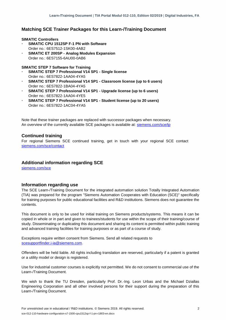
Matching SCE Trainer Packages for this Learn-/Training Document
SIMATIC Controllers • SIMATIC CPU 1512SP F-1 PN with Software
Order no.: 6ES7512-1SK00-4AB2
• SIMATIC ET 200SP - Analog Modules Expansion
Order no.: 6ES7155-6AU00-0AB6
SIMATIC STEP 7 Software for Training • SIMATIC STEP 7 Professional V14 SP1 - Single license
Order no.: 6ES7822-1AA04-4YA5
• SIMATIC STEP 7 Professional V14 SP1 - Classroom license (up to 6 users)
Order no.: 6ES7822-1BA04-4YA5
• SIMATIC STEP 7 Professional V14 SP1 - Upgrade license (up to 6 users)
Order no.: 6ES7822-1AA04-4YE5
• SIMATIC STEP 7 Professional V14 SP1 - Student license (up to 20 users)
Order no.: 6ES7822-1AC04-4YA5
Note that these trainer packages are replaced with successor packages when necessary.
An overview of the currently available SCE packages is available at: siemens.com/sce/tp
Continued training For regional Siemens SCE continued training, get in touch with your regional SCE contact
siemens.com/sce/contact
Additional information regarding SCE siemens.com/sce
Information regarding use The SCE Learn-/Training Document for the integrated automation solution Totally Integrated Automation
(TIA) was prepared for the program "Siemens Automation Cooperates with Education (SCE)" specifically
for training purposes for public educational facilities and R&D institutions. Siemens does not guarantee the
contents.
This document is only to be used for initial training on Siemens products/systems. This means it can be
copied in whole or in part and given to trainees/students for use within the scope of their training/course of
study. Disseminating or duplicating this document and sharing its content is permitted within public training
and advanced training facilities for training purposes or as part of a course of study.
Exceptions require written consent from Siemens. Send all related requests to
Offenders will be held liable. All rights including translation are reserved, particularly if a patent is granted
or a utility model or design is registered.
Use for industrial customer courses is explicitly not permitted. We do not consent to commercial use of the
Learn-/Training Document.
We wish to thank the TU Dresden, particularly Prof. Dr.-Ing. Leon Urbas and the Michael Dziallas
Engineering Corporation and all other involved persons for their support during the preparation of this
Learn-/Training Document.
Learn-/Training Document | TIA Portal Modul 012-110, Edition 02/2019 | Digital Industries, FA
For unrestricted use in educational / R&D institutions. © Siemens 2019. All rights reserved. 3
sce-012-110-hardware-configuration-s7-1500-cpu1512sp-f-1-pn-r1803-en.docx
Table of contents
1 Objective ............................................................................................................................................... 5
2 Requirement ......................................................................................................................................... 5
3 Hardware and software required .......................................................................................................... 5
4 Theory ................................................................................................................................................... 7
4.1 Automation system SIMATIC S7-1500 with ET 200SP CPU ....................................................... 7
4.2 Installation and operation of the SIMATIC ET 200SP CPU .......................................................... 8
4.2.1 Range of modules ................................................................................................................. 9
4.2.2 Example configuration ........................................................................................................ 13
4.3 Operator controls and display elements of the CPU 1512SP F-1 PN ....................................... 14
4.3.1 Front view of the CPU 1512SP F-1 PN with BA 2xR bus adapter ..................................... 14
4.3.2 Status and error displays .................................................................................................... 15
4.3.3 SIMATIC memory card ....................................................................................................... 15
4.3.4 Mode switch ........................................................................................................................ 16
4.3.5 Memory areas of the CPU 1512SP F-1 PN and the SIMATIC memory card ..................... 17
4.4 Programming software STEP 7 Professional V14 (TIA Portal V14) ........................................... 18
4.4.1 Project ................................................................................................................................. 19
4.4.2 Hardware configuration ....................................................................................................... 19
4.4.3 Centralized and distributed automation structure ............................................................... 20
4.4.4 Planning the hardware ........................................................................................................ 20
4.4.5 TIA Portal – Project view and portal view ........................................................................... 21
4.4.6 Basic settings for the TIA Portal ......................................................................................... 23
4.4.7 Setting the IP address on the programming device............................................................ 25
4.4.8 Setting the IP address in the CPU ...................................................................................... 28
4.4.9 Formatting a memory card in the CPU ............................................................................... 31
4.4.10 Resetting the CPU to factory settings ................................................................................. 32
4.4.11 Reading out the firmware version of the CPU 1512SP F-1 PN .......................................... 33
5 Task .................................................................................................................................................... 34
6 Planning .............................................................................................................................................. 34
7 Structured step-by-step instructions ................................................................................................... 35
Learn-/Training Document | TIA Portal Modul 012-110, Edition 02/2019 | Digital Industries, FA
For unrestricted use in educational / R&D institutions. © Siemens 2019. All rights reserved. 4
sce-012-110-hardware-configuration-s7-1500-cpu1512sp-f-1-pn-r1803-en.docx
7.1 Creating a new project ................................................................................................................ 35
7.2 Inserting the CPU 1512SP F-1 PN ............................................................................................. 36
7.3 Configuration of the Ethernet interface of the CPU 1512SP F-1 PN .......................................... 40
7.4 Configuration of fail-safe operation of the CPU 1512SP F-1 PN ................................................ 41
7.5 Configuration of access level for the CPU 1512SP F-1 PN ....................................................... 42
7.6 Inserting the digital input modules DI 8x24VDC HF ................................................................... 43
7.7 Inserting the digital output modules DQ 8xDC24V / 0.5A HF ..................................................... 45
7.8 Changing components in the hardware configuration ................................................................ 46
7.9 Inserting the server module ........................................................................................................ 47
7.10 Configuration of address ranges for DI/DO: 0…1....................................................................... 48
7.11 Configuration of the potential groups of the BaseUnits .............................................................. 49
7.12 Saving and compiling the hardware configuration ...................................................................... 51
7.13 Downloading the hardware configuration to the device .............................................................. 53
7.14 Downloading the hardware configuration to the PLCSIM simulation (optional) ......................... 58
7.15 Archiving the project ................................................................................................................... 66
7.16 Checklist – step-by-step instructions .......................................................................................... 67
8 Exercise .............................................................................................................................................. 68
8.1 Task description – Exercise ........................................................................................................ 68
8.2 Planning ...................................................................................................................................... 68
8.3 Checklist – Exercise ................................................................................................................... 69
9 Additional information ......................................................................................................................... 70
Learn-/Training Document | TIA Portal Modul 012-110, Edition 02/2019 | Digital Industries, FA
For unrestricted use in educational / R&D institutions. © Siemens 2019. All rights reserved. 5
sce-012-110-hardware-configuration-s7-1500-cpu1512sp-f-1-pn-r1803-en.docx
Specific hardware configuration – SIMATIC S7-1500 CPU 1512SP F-1 PN
1 Objective
In this section, you will start by learning how to create a project. In a portion of a task, you will
also be shown how to recognize previously installed hardware and add it to a project using the
TIA Portal. You will then be shown how to configure the hardware.
The SIMATIC S7 controllers listed in chapter 3 can be used.
2 Requirement
Nothing is required from other chapters to successfully complete this chapter.
3 Hardware and software required
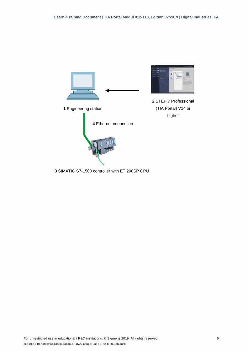
1 Engineering Station: hardware and operating system (for additional information, see Readme
file on the TIA Portal Installation DVDs)
2 SIMATIC STEP 7 Professional software in the TIA Portal V14 or higher
3 SIMATIC S7-1500 controller with ET 200SP CPU Firmware V2.0 or higher with memory card
and at least 16 DI/16 DO as well as 2 AI/1 AO
Example configuration
1x controller CPU 1512SP F-1 PN with bus adapter BA 2xRJ45
2x IO module 8x digital input DI 8x24VDC HF
2x IO module 8x digital output DQ 8x24VDC/0.5A HF
2x IO module 2x analog input AI 2xU/I 2.4-wire HS
1x IO module 2x analog output AQ 2xU/I HS
1x server module
4 Ethernet connection between the engineering station and controller
Learn-/Training Document | TIA Portal Modul 012-110, Edition 02/2019 | Digital Industries, FA
For unrestricted use in educational / R&D institutions. © Siemens 2019. All rights reserved. 6
sce-012-110-hardware-configuration-s7-1500-cpu1512sp-f-1-pn-r1803-en.docx
2 STEP 7 Professional
(TIA Portal) V14 or
higher
3 SIMATIC S7-1500 controller with ET 200SP CPU
1 Engineering station
4 Ethernet connection
Learn-/Training Document | TIA Portal Modul 012-110, Edition 02/2019 | Digital Industries, FA
For unrestricted use in educational / R&D institutions. © Siemens 2019. All rights reserved. 7
sce-012-110-hardware-configuration-s7-1500-cpu1512sp-f-1-pn-r1803-en.docx
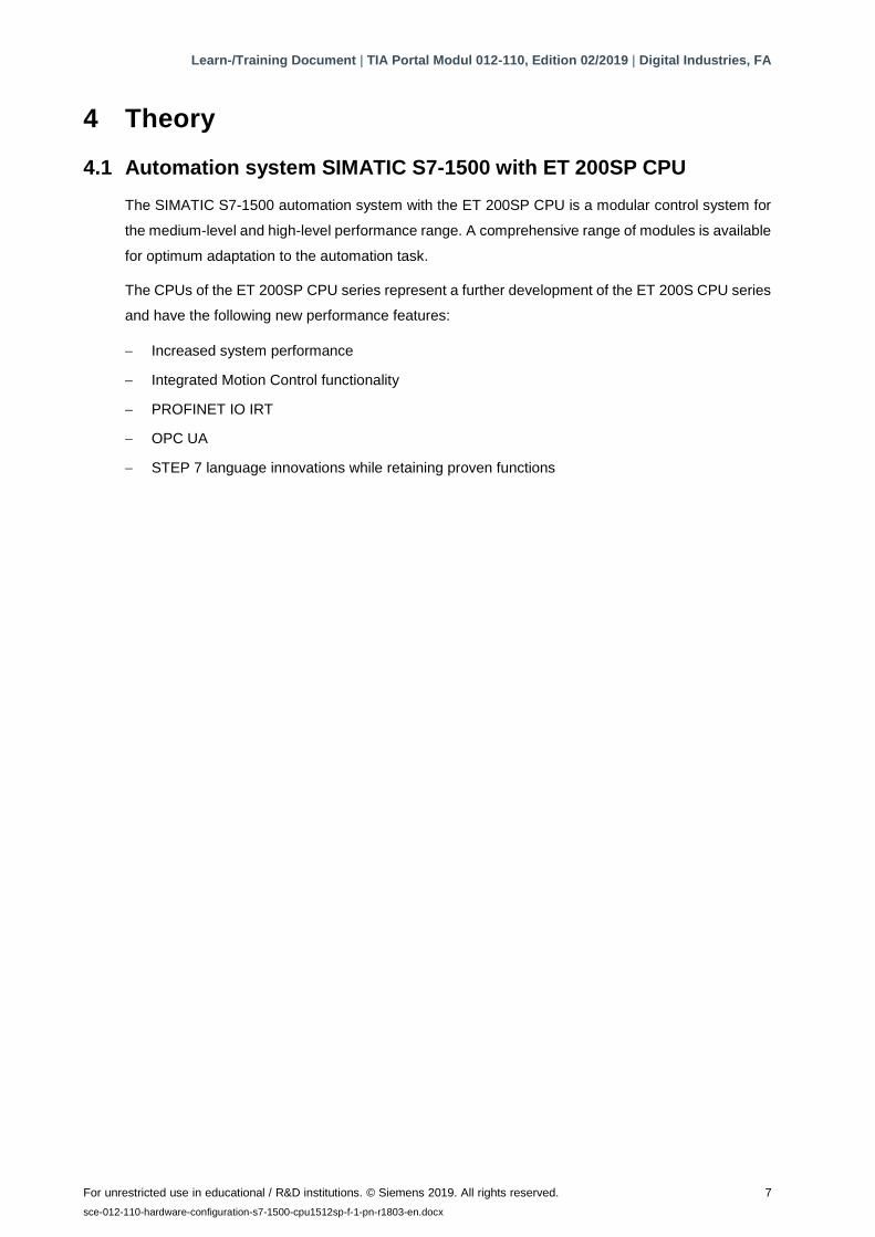
4 Theory
4.1 Automation system SIMATIC S7-1500 with ET 200SP CPU
The SIMATIC S7-1500 automation system with the ET 200SP CPU is a modular control system for
the medium-level and high-level performance range. A comprehensive range of modules is available
for optimum adaptation to the automation task.
The CPUs of the ET 200SP CPU series represent a further development of the ET 200S CPU series
and have the following new performance features:
− Increased system performance
− Integrated Motion Control functionality
− PROFINET IO IRT
− OPC UA
− STEP 7 language innovations while retaining proven functions
Learn-/Training Document | TIA Portal Modul 012-110, Edition 02/2019 | Digital Industries, FA
For unrestricted use in educational / R&D institutions. © Siemens 2019. All rights reserved. 8
sce-012-110-hardware-configuration-s7-1500-cpu1512sp-f-1-pn-r1803-en.docx
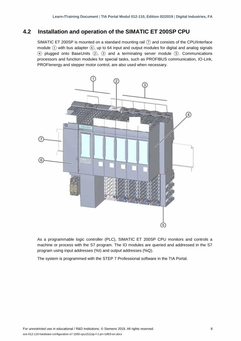
4.2 Installation and operation of the SIMATIC ET 200SP CPU
SIMATIC ET 200SP is mounted on a standard mounting rail ⑦ and consists of the CPU/interface
module ① with bus adapter ⑥, up to 64 input and output modules for digital and analog signals
④ plugged onto BaseUnits ②, ③ and a terminating server module ⑤. Communications
processors and function modules for special tasks, such as PROFIBUS communication, IO-Link,
PROFIenergy and stepper motor control, are also used when necessary.
As a programmable logic controller (PLC), SIMATIC ET 200SP CPU monitors and controls a
machine or process with the S7 program. The IO modules are queried and addressed in the S7
program using input addresses (%I) and output addresses (%Q).
The system is programmed with the STEP 7 Professional software in the TIA Portal.
①
④ ②

Learn-/Training Document | TIA Portal Modul 012-110, Edition 02/2019 | Digital Industries, FA
For unrestricted use in educational / R&D institutions. © Siemens 2019. All rights reserved. 9
sce-012-110-hardware-configuration-s7-1500-cpu1512sp-f-1-pn-r1803-en.docx
4.2.1 Range of modules
The SIMATIC S7-1500 controller of the ET 200SP CPU series is a modular automation system with
the following range of modules:
Central processing units (CPUs) with pluggable bus adapters
The CPUs, which are available for different performance levels, run the user program. In addition,
the integrated system power supply provides power to the other modules over the backplane bus.
Bus adapters enable users to use the connection system of their choice.
Additional properties and functions of the CPU:
– Communication via Ethernet
– Communication via PROFIBUS/PROFINET
– HMI communication on operator control and monitoring devices
– Web server
– Integrated technology functions (e.g.: PID controller, Motion Control, etc.)
– System diagnostics
– Trace functionality
– Integrated security (e.g.: know-how, copy, access, data integrity protection)
Learn-/Training Document | TIA Portal Modul 012-110, Edition 02/2019 | Digital Industries, FA
For unrestricted use in educational / R&D institutions. © Siemens 2019. All rights reserved. 10
sce-012-110-hardware-configuration-s7-1500-cpu1512sp-f-1-pn-r1803-en.docx
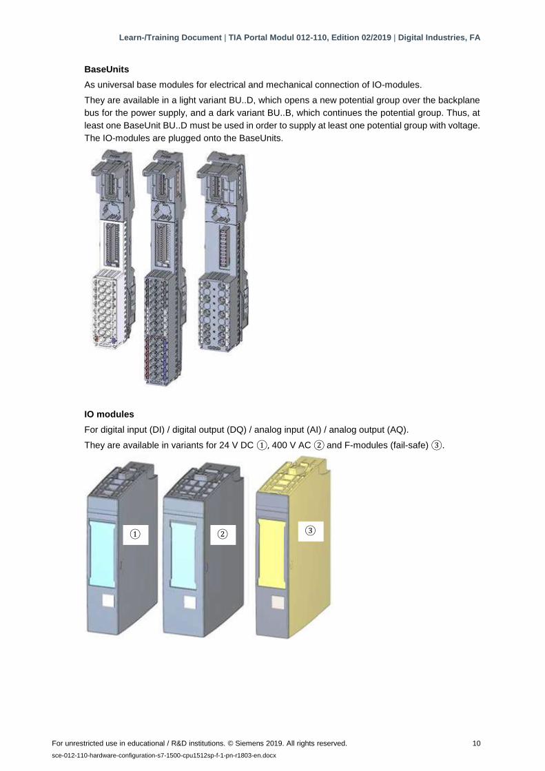
BaseUnits
As universal base modules for electrical and mechanical connection of IO-modules.
They are available in a light variant BU..D, which opens a new potential group over the backplane
bus for the power supply, and a dark variant BU..B, which continues the potential group. Thus, at
least one BaseUnit BU..D must be used in order to supply at least one potential group with voltage.
The IO-modules are plugged onto the BaseUnits.
IO modules
For digital input (DI) / digital output (DQ) / analog input (AI) / analog output (AQ).
They are available in variants for 24 V DC ①, 400 V AC ② and F-modules (fail-safe) ③.
① ② ③
Learn-/Training Document | TIA Portal Modul 012-110, Edition 02/2019 | Digital Industries, FA
For unrestricted use in educational / R&D institutions. © Siemens 2019. All rights reserved. 11
sce-012-110-hardware-configuration-s7-1500-cpu1512sp-f-1-pn-r1803-en.docx
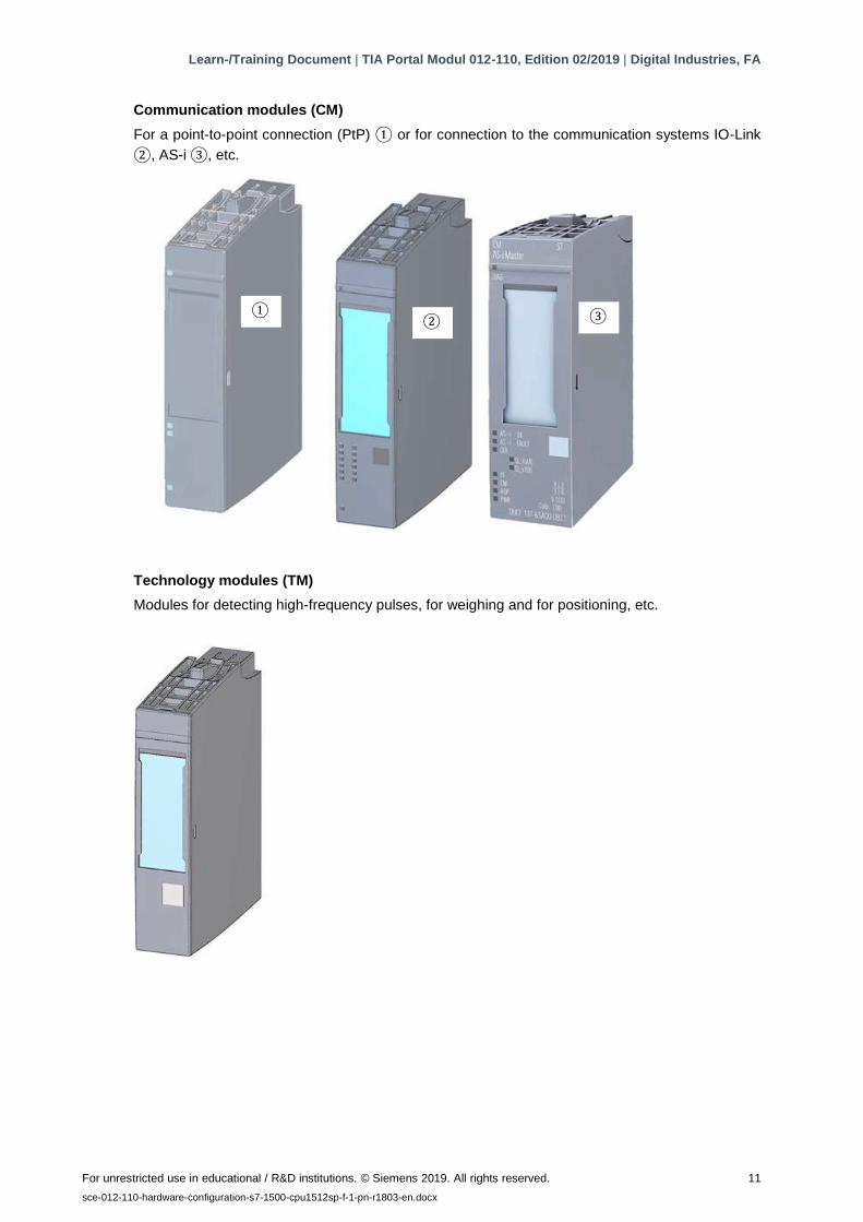
Communication modules (CM)
For a point-to-point connection (PtP) ① or for connection to the communication systems IO-Link
②, AS-i ③, etc.
Technology modules (TM)
Modules for detecting high-frequency pulses, for weighing and for positioning, etc.
① ② ③
Learn-/Training Document | TIA Portal Modul 012-110, Edition 02/2019 | Digital Industries, FA
For unrestricted use in educational / R&D institutions. © Siemens 2019. All rights reserved. 12
sce-012-110-hardware-configuration-s7-1500-cpu1512sp-f-1-pn-r1803-en.docx
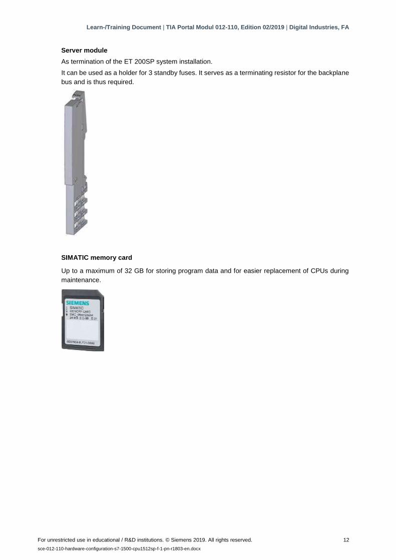
Server module
As termination of the ET 200SP system installation.
It can be used as a holder for 3 standby fuses. It serves as a terminating resistor for the backplane
bus and is thus required.
SIMATIC memory card
Up to a maximum of 32 GB for storing program data and for easier replacement of CPUs during
maintenance.
Learn-/Training Document | TIA Portal Modul 012-110, Edition 02/2019 | Digital Industries, FA
For unrestricted use in educational / R&D institutions. © Siemens 2019. All rights reserved. 13
sce-012-110-hardware-configuration-s7-1500-cpu1512sp-f-1-pn-r1803-en.docx
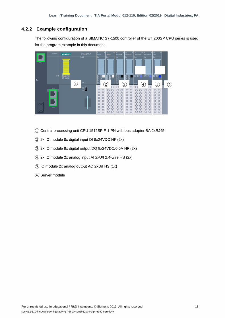
4.2.2 Example configuration
The following configuration of a SIMATIC S7-1500 controller of the ET 200SP CPU series is used
for the program example in this document.
① Central processing unit CPU 1512SP F-1 PN with bus adapter BA 2xRJ45
② 2x IO module 8x digital input DI 8x24VDC HF (2x)
③ 2x IO module 8x digital output DQ 8x24VDC/0.5A HF (2x)
④ 2x IO module 2x analog input AI 2xU/I 2.4-wire HS (2x)
⑤ IO module 2x analog output AQ 2xU/I HS (1x)
⑥ Server module
④ ⑤ ⑥
① ② ③ ④ ⑤ ⑥

Learn-/Training Document | TIA Portal Modul 012-110, Edition 02/2019 | Digital Industries, FA
For unrestricted use in educational / R&D institutions. © Siemens 2019. All rights reserved. 14
sce-012-110-hardware-configuration-s7-1500-cpu1512sp-f-1-pn-r1803-en.docx
4.3 Operator controls and display elements of the CPU 1512SP F-1 PN
The following figure shows the operator controls and display elements of a CPU 1512SP F-1 PN
and a BA 2xRJ45 bus adapter. For other CPUs, the number of elements and their arrangement
differ from this figure.
4.3.1 Front view of the CPU 1512SP F-1 PN with BA 2xR bus adapter
① Mounting rail release
② Labeling strips
③ LEDs for status and error displays
④ LED for display of supply voltage
⑤ Mode switch
⑥ Slot for the SIMATIC memory card
⑦ Connection for supply voltage (included in the product package)
⑧ Cable support and fixing means for Port P3 of the PROFINET interface
⑨ LEDs for status displays of the PROFINET interface for ports P1, P2 and P3
⑩ Port P3 of the PROFINET interface: RJ45 socket on the CPU
⑪ Single view of the bus adapter
⑫ Port P1 R of the PROFINET interface: RJ45 socket on bus adapter BA 2×RJ45
⑬ Port P2 R of the PROFINET interface: RJ45 socket on bus adapter BA 2×RJ45

Learn-/Training Document | TIA Portal Modul 012-110, Edition 02/2019 | Digital Industries, FA
For unrestricted use in educational / R&D institutions. © Siemens 2019. All rights reserved. 15
sce-012-110-hardware-configuration-s7-1500-cpu1512sp-f-1-pn-r1803-en.docx
4.3.2 Status and error displays
The CPU 1512SP-1 PN and bus adapter BA 2xRJ45 are equipped with the following LEDs:
① RUN/STOP-LED (yellow/green LED)
② ERROR LED (red LED)
③ MAINT LED (yellow LED)
④ LINK RX/TX-LED for ports X1 P1 and X1 P2 (green LEDs on bus adapter)
⑤ POWER LED (green LED)
⑥ LINK RX/TX LED for port X1 P3 (green LED on CPU)
4.3.3 SIMATIC memory card
A SIMATIC micro memory card (MMC) is used as a memory module for the CPUs. This is a pre-
formatted memory card that is compatible with the Windows file system. It is available in different
memory sizes and for the following purposes:
– Portable data storage medium
– Program card
– Firmware update card
The MMC must be inserted for operation of the CPU because the CPUs have no integrated load
memory. A commercially available SD card reader is needed for reading/writing of the SIMATIC
memory card with the programming device or PC. Files can then be copied directly to the SIMATIC
memory card with Windows Explorer.
Note:
– It is recommended that the SIMATIC memory card only be inserted and removed when the
CPU is in POWER OFF state.
Learn-/Training Document | TIA Portal Modul 012-110, Edition 02/2019 | Digital Industries, FA
For unrestricted use in educational / R&D institutions. © Siemens 2019. All rights reserved. 16
sce-012-110-hardware-configuration-s7-1500-cpu1512sp-f-1-pn-r1803-en.docx
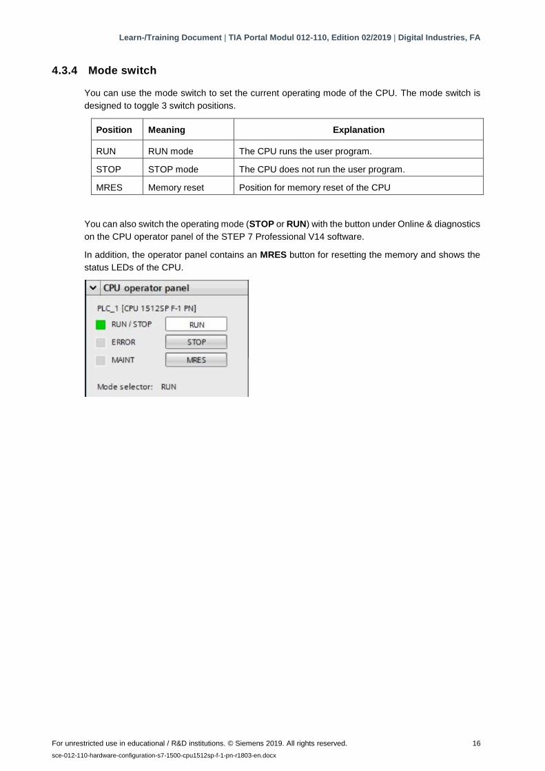
4.3.4 Mode switch
You can use the mode switch to set the current operating mode of the CPU. The mode switch is
designed to toggle 3 switch positions.
Position Meaning Explanation
RUN RUN mode The CPU runs the user program.
STOP STOP mode The CPU does not run the user program.
MRES Memory reset Position for memory reset of the CPU
You can also switch the operating mode (STOP or RUN) with the button under Online & diagnostics
on the CPU operator panel of the STEP 7 Professional V14 software.
In addition, the operator panel contains an MRES button for resetting the memory and shows the
status LEDs of the CPU.
Learn-/Training Document | TIA Portal Modul 012-110, Edition 02/2019 | Digital Industries, FA
For unrestricted use in educational / R&D institutions. © Siemens 2019. All rights reserved. 17
sce-012-110-hardware-configuration-s7-1500-cpu1512sp-f-1-pn-r1803-en.docx
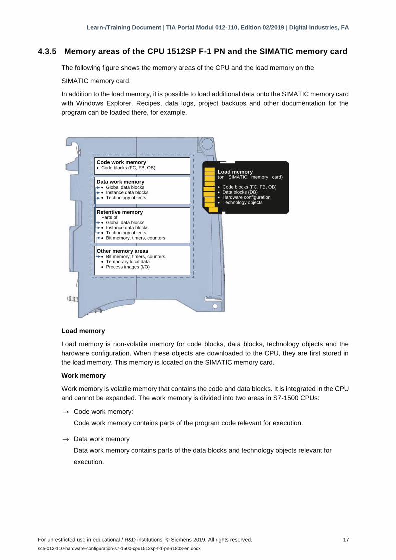
4.3.5 Memory areas of the CPU 1512SP F-1 PN and the SIMATIC memory card
The following figure shows the memory areas of the CPU and the load memory on the
SIMATIC memory card.
In addition to the load memory, it is possible to load additional data onto the SIMATIC memory card
with Windows Explorer. Recipes, data logs, project backups and other documentation for the
program can be loaded there, for example.
Load memory
Load memory is non-volatile memory for code blocks, data blocks, technology objects and the
hardware configuration. When these objects are downloaded to the CPU, they are first stored in
the load memory. This memory is located on the SIMATIC memory card.
Work memory
Work memory is volatile memory that contains the code and data blocks. It is integrated in the CPU
and cannot be expanded. The work memory is divided into two areas in S7-1500 CPUs:
→ Code work memory:
Code work memory contains parts of the program code relevant for execution.
→ Data work memory
Data work memory contains parts of the data blocks and technology objects relevant for
execution.
Code work memory • Code blocks (FC, FB, OB)
Data work memory • Global data blocks • Instance data blocks • Technology objects
Retentive memory Parts of: • Global data blocks • Instance data blocks • Technology objects • Bit memory, timers, counters
Other memory areas • Bit memory, timers, counters • Temporary local data • Process images (I/O)
Load memory (on SIMATIC memory card)
• Code blocks (FC, FB, OB) • Data blocks (DB) • Hardware configuration • Technology objects
Learn-/Training Document | TIA Portal Modul 012-110, Edition 02/2019 | Digital Industries, FA
For unrestricted use in educational / R&D institutions. © Siemens 2019. All rights reserved. 18
sce-012-110-hardware-configuration-s7-1500-cpu1512sp-f-1-pn-r1803-en.docx
During the operating mode transition from POWER ON to Start and from STOP to Start, tags of
global data blocks, instance data blocks and technology objects are initialized with their start values.
Retentive tags keep their current values saved in the retentive memory.
Retentive memory
Retentive memory is non-volatile memory for backing up certain data in case of power failure. The
tags and operand areas defined as retentive are saved in retentive memory. This data is retained
for the duration of a shutdown or power failure.
All other program tags are set to their start values with an operating mode transition from POWER
ON to Start and from STOP to Start.
The content of the retentive memory is deleted by the following actions:
– Memory reset
– Reset to factory settings
Note:
– Certain tags of technology objects are also saved in retentive memory. These are not deleted
with a memory reset.
4.4 Programming software STEP 7 Professional V14 (TIA Portal V14)
The STEP 7 Professional V14 (TIA Portal V14) software is the programming tool for the following
automation systems:
– SIMATIC S7-1500
– SIMATIC S7-1200
– SIMATIC S7-300
– SIMATIC S7-400
– SIMATIC WinAC
With STEP 7 Professional V14, the following system automation functions can be used:
– Configuration and parameter assignment of the hardware
– Specifying the communication
– Programming
– Testing, commissioning and service with operational/diagnostic functions
– Documentation
– Creation of visualizations for SIMATIC Basic Panels with integrated WinCC Basic.
– Visualization solutions for PCs and other panels can also be created with other WinCC
packages.
All functions are supported by an extensive online help.

Learn-/Training Document | TIA Portal Modul 012-110, Edition 02/2019 | Digital Industries, FA
For unrestricted use in educational / R&D institutions. © Siemens 2019. All rights reserved. 19
sce-012-110-hardware-configuration-s7-1500-cpu1512sp-f-1-pn-r1803-en.docx
4.4.1 Project
You create a project in the TIA Portal for performing an automation and visualization task. A project
in the TIA Portal contains the configuration data for the installation and networking of devices as
well as the programs and the configuration of the visualization.
4.4.2 Hardware configuration
The hardware configuration contains the configuration of the devices, consisting of the automation
system hardware, the intelligent field devices and the hardware for visualization. The configuration
of the networks specifies the communication between the various hardware components. Individual
hardware components are inserted from catalogs into the hardware configuration.
The automation system hardware is composed of controllers (CPUs), signal modules for input and
output signals (SMs) and communication and interface modules (CP, IM). System power supply
and load power supply modules (PS, PM) are also available for supplying energy to the modules.
The signal modules and the intelligent field devices connect the input and output data process that
is to be automated and visualized to the automation system.
Figure 1: Example of hardware configuration with centralized and distributed structures
The hardware configuration enables automation and visualization solutions to be downloaded to
the automation system and the controller to have access to the connected signal modules.
Visualization
Centralized structure
Actuators/sensors
Distributed structure
Learn-/Training Document | TIA Portal Modul 012-110, Edition 02/2019 | Digital Industries, FA
For unrestricted use in educational / R&D institutions. © Siemens 2019. All rights reserved. 20
sce-012-110-hardware-configuration-s7-1500-cpu1512sp-f-1-pn-r1803-en.docx
4.4.3 Centralized and distributed automation structure
Figure 1 shows an automation structure containing both centralized and distributed structures.
In centralized structures, the input and output signals of the process are transmitted over
conventional wiring to the signal modules, which are connected directly to the controller.
Conventional wiring means that sensors and actuators are connected using 2-wire or 4-wire cables.
These days, the use of distributed structures is predominant. In this case, the sensors and
actuators only have to be conventionally wired up to the signal modules of the field devices. The
signal is transmitted from the field devices to the controller via an industrial communication system.
Both classic fieldbuses such as PROFIBUS, Modbus and Foundation Fieldbus and Ethernet-based
communication systems such as PROFINET are used for industrial communication.
The communication system can also be used to connect intelligent field devices on which
independent programs run. These programs can also be created with the TIA Portal.
4.4.4 Planning the hardware
Before you can configure the hardware, you must plan it. In general, you start by selecting the
required controllers and the number needed. Next, you select the communication modules and
signal modules. The signal modules are selected based on the number and type of inputs and
outputs needed. Finally, an adequate power supply must be selected for each controller or field
device.
The functionality needed and the environmental conditions are of critical importance for planning
the hardware configuration. For example, the temperature range in the application area is one of
the limiting factors for selecting possible devices. Fail-safe capability could be another requirement,
for example.
The TIA Selection Tool (select Automation technology → TIA Selection Tool and follow the
instructions) offers you support.
Notes
– TIA Selection Tool requires Java.
– To obtain the device specifications online, look for the manual described as "Product Manual"
or "Manual" among the various manuals listed.
Learn-/Training Document | TIA Portal Modul 012-110, Edition 02/2019 | Digital Industries, FA
For unrestricted use in educational / R&D institutions. © Siemens 2019. All rights reserved. 21
sce-012-110-hardware-configuration-s7-1500-cpu1512sp-f-1-pn-r1803-en.docx
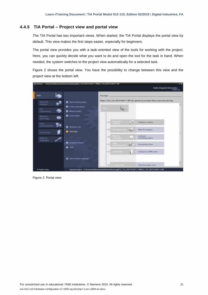
4.4.5 TIA Portal – Project view and portal view
The TIA Portal has two important views. When started, the TIA Portal displays the portal view by
default. This view makes the first steps easier, especially for beginners.
The portal view provides you with a task-oriented view of the tools for working with the project.
Here, you can quickly decide what you want to do and open the tool for the task in hand. When
needed, the system switches to the project view automatically for a selected task.
Figure 2 shows the portal view. You have the possibility to change between this view and the
project view at the bottom left.
Figure 2: Portal view
Learn-/Training Document | TIA Portal Modul 012-110, Edition 02/2019 | Digital Industries, FA
For unrestricted use in educational / R&D institutions. © Siemens 2019. All rights reserved. 22
sce-012-110-hardware-configuration-s7-1500-cpu1512sp-f-1-pn-r1803-en.docx
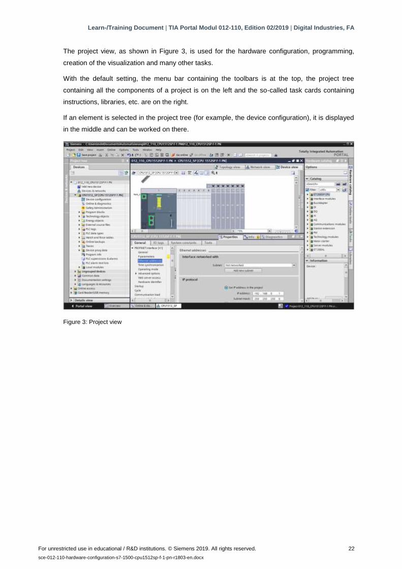
The project view, as shown in Figure 3, is used for the hardware configuration, programming,
creation of the visualization and many other tasks.
With the default setting, the menu bar containing the toolbars is at the top, the project tree
containing all the components of a project is on the left and the so-called task cards containing
instructions, libraries, etc. are on the right.
If an element is selected in the project tree (for example, the device configuration), it is displayed
in the middle and can be worked on there.
Figure 3: Project view

Learn-/Training Document | TIA Portal Modul 012-110, Edition 02/2019 | Digital Industries, FA
For unrestricted use in educational / R&D institutions. © Siemens 2019. All rights reserved. 23
sce-012-110-hardware-configuration-s7-1500-cpu1512sp-f-1-pn-r1803-en.docx
4.4.6 Basic settings for the TIA Portal
→ The user can make customized default settings for certain settings in the TIA Portal. A couple
of important settings are shown here.
→ In the menu of the Project view, select → "Options" and then → "Settings".

Learn-/Training Document | TIA Portal Modul 012-110, Edition 02/2019 | Digital Industries, FA
For unrestricted use in educational / R&D institutions. © Siemens 2019. All rights reserved. 24
sce-012-110-hardware-configuration-s7-1500-cpu1512sp-f-1-pn-r1803-en.docx
→ A basic setting is the choice of user interface language and the language for the program
display. English is used for both settings in this document.
→ In the → "General" item of "Settings", select → "English" for "User interface language" and →
"International" for "Mnemonics".
Note:
– These settings can always be changed back and forth between "English" and "International".
→ To use safety CPUs (e.g. CPU 1512SP F-1 PN) without the use of safety technology, we
recommend you disable automatic generation of the safety program before creating a project.
→ In the → "STEP 7 Safety" item of "Settings", clear the → "Generate default fail-safe program"
check box.
Learn-/Training Document | TIA Portal Modul 012-110, Edition 02/2019 | Digital Industries, FA
For unrestricted use in educational / R&D institutions. © Siemens 2019. All rights reserved. 25
sce-012-110-hardware-configuration-s7-1500-cpu1512sp-f-1-pn-r1803-en.docx
4.4.7 Setting the IP address on the programming device
In order to program the CPU of a SIMATIC S7-1500 controller from a PC, programming device or
laptop, a TCP/IP connection is needed.
For the computer and SIMATIC S7-1500 to communicate with one another via TCP/IP, it is
important that the IP addresses of both devices match.
First, it is shown how to set the IP address of a computer with
Windows 10.
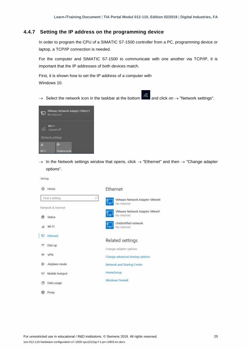
→ Select the network icon in the taskbar at the bottom and click on → "Network settings".
→ In the Network settings window that opens, click → "Ethernet" and then → "Change adapter
options".

Learn-/Training Document | TIA Portal Modul 012-110, Edition 02/2019 | Digital Industries, FA
For unrestricted use in educational / R&D institutions. © Siemens 2019. All rights reserved. 26
sce-012-110-hardware-configuration-s7-1500-cpu1512sp-f-1-pn-r1803-en.docx
→ Select the desired → "LAN connection" you want to use to connect to the controller and click
→ "Properties".
→ Select the → "Properties" for → "Internet Protocol Version 4 (TCP/IPv4)".
Learn-/Training Document | TIA Portal Modul 012-110, Edition 02/2019 | Digital Industries, FA
For unrestricted use in educational / R&D institutions. © Siemens 2019. All rights reserved. 27
sce-012-110-hardware-configuration-s7-1500-cpu1512sp-f-1-pn-r1803-en.docx
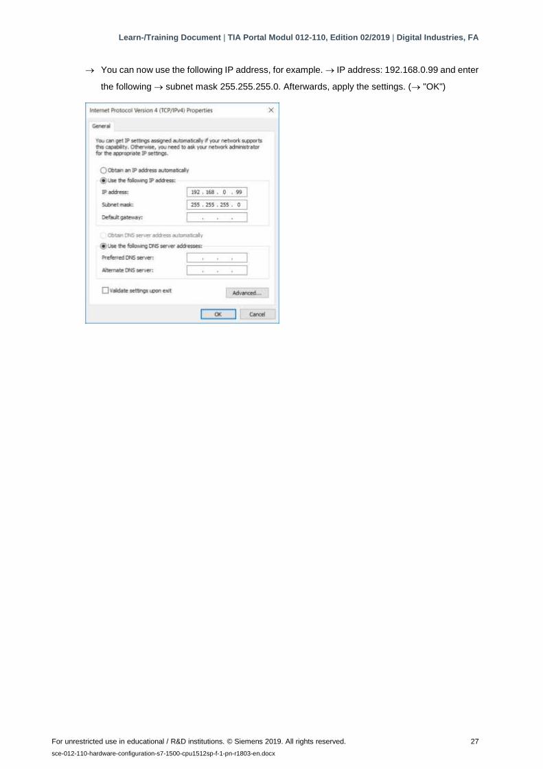
→ You can now use the following IP address, for example. → IP address: 192.168.0.99 and enter
the following → subnet mask 255.255.255.0. Afterwards, apply the settings. (→ "OK")
Learn-/Training Document | TIA Portal Modul 012-110, Edition 02/2019 | Digital Industries, FA
For unrestricted use in educational / R&D institutions. © Siemens 2019. All rights reserved. 28
sce-012-110-hardware-configuration-s7-1500-cpu1512sp-f-1-pn-r1803-en.docx
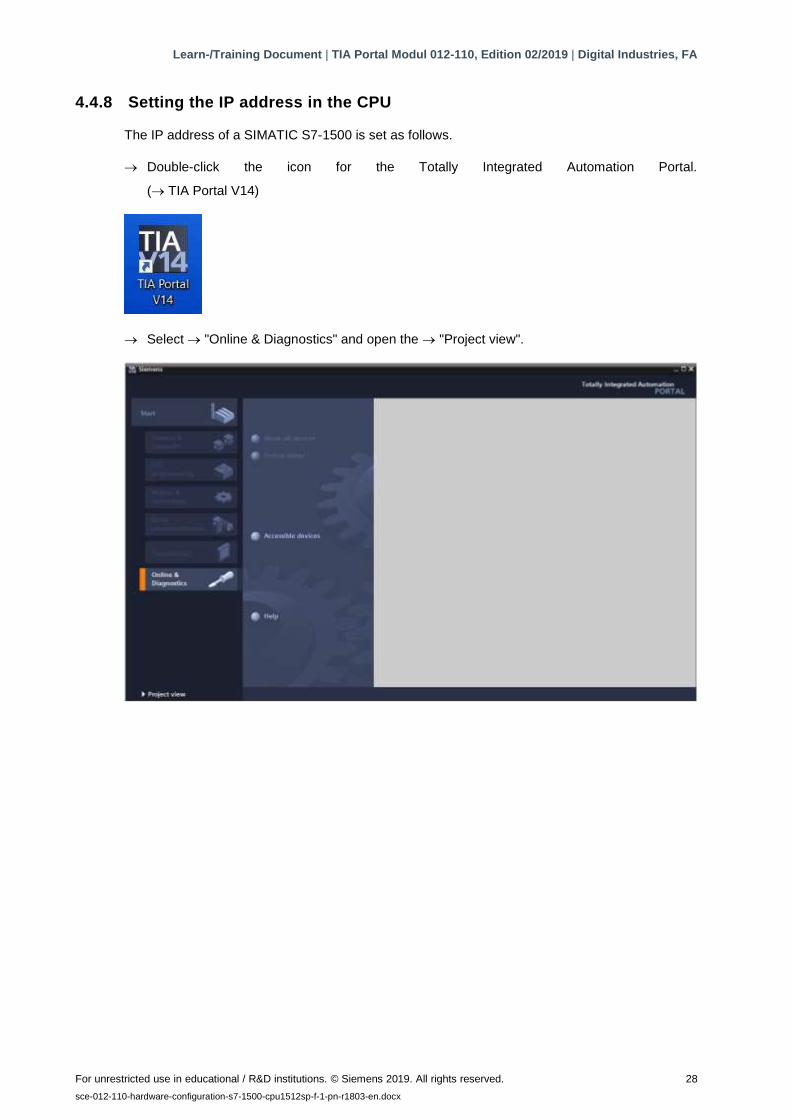
4.4.8 Setting the IP address in the CPU
The IP address of a SIMATIC S7-1500 is set as follows.
→ Double-click the icon for the Totally Integrated Automation Portal.
(→ TIA Portal V14)
→ Select → "Online & Diagnostics" and open the → "Project view".
Learn-/Training Document | TIA Portal Modul 012-110, Edition 02/2019 | Digital Industries, FA
For unrestricted use in educational / R&D institutions. © Siemens 2019. All rights reserved. 29
sce-012-110-hardware-configuration-s7-1500-cpu1512sp-f-1-pn-r1803-en.docx
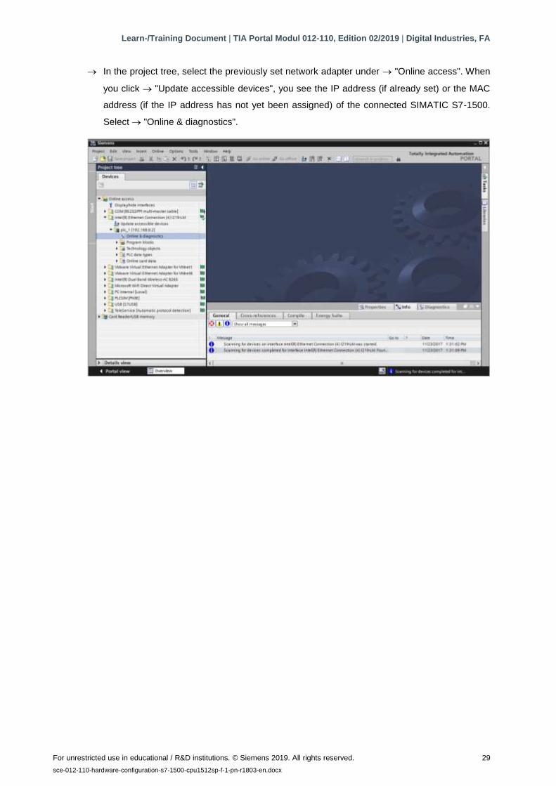
→ In the project tree, select the previously set network adapter under → "Online access". When
you click → "Update accessible devices", you see the IP address (if already set) or the MAC
address (if the IP address has not yet been assigned) of the connected SIMATIC S7-1500.
Select → "Online & diagnostics".
Learn-/Training Document | TIA Portal Modul 012-110, Edition 02/2019 | Digital Industries, FA
For unrestricted use in educational / R&D institutions. © Siemens 2019. All rights reserved. 30
sce-012-110-hardware-configuration-s7-1500-cpu1512sp-f-1-pn-r1803-en.docx
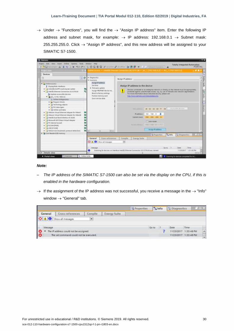
→ Under → "Functions", you will find the → "Assign IP address" item. Enter the following IP
address and subnet mask, for example: → IP address: 192.168.0.1 → Subnet mask:
255.255.255.0. Click → "Assign IP address", and this new address will be assigned to your
SIMATIC S7-1500.
Note:
– The IP address of the SIMATIC S7-1500 can also be set via the display on the CPU, if this is
enabled in the hardware configuration.
→ If the assignment of the IP address was not successful, you receive a message in the → "Info"
window → "General" tab.

Learn-/Training Document | TIA Portal Modul 012-110, Edition 02/2019 | Digital Industries, FA
For unrestricted use in educational / R&D institutions. © Siemens 2019. All rights reserved. 31
sce-012-110-hardware-configuration-s7-1500-cpu1512sp-f-1-pn-r1803-en.docx
4.4.9 Formatting a memory card in the CPU
→ If the IP address could not be assigned, the program data on the CPU must be deleted. This
is done in 2 steps: → "Format memory card" and → "Reset to factory settings".
→ First, select the → "Format memory card" function and click the → "Format" button.
→ Confirm the prompt "Do you really want to format the memory card?" with → "Yes".
→ Stop the CPU if necessary. (→ "Yes")
Learn-/Training Document | TIA Portal Modul 012-110, Edition 02/2019 | Digital Industries, FA
For unrestricted use in educational / R&D institutions. © Siemens 2019. All rights reserved. 32
sce-012-110-hardware-configuration-s7-1500-cpu1512sp-f-1-pn-r1803-en.docx
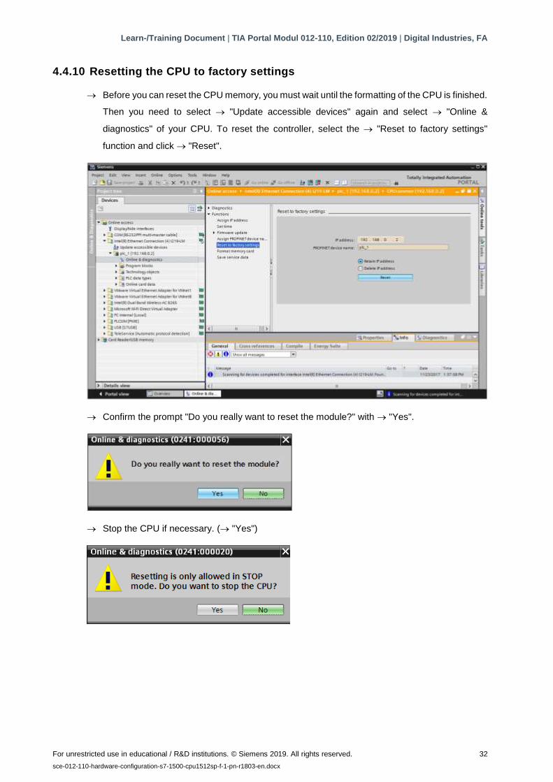
4.4.10 Resetting the CPU to factory settings
→ Before you can reset the CPU memory, you must wait until the formatting of the CPU is finished.
Then you need to select → "Update accessible devices" again and select → "Online &
diagnostics" of your CPU. To reset the controller, select the → "Reset to factory settings"
function and click → "Reset".
→ Confirm the prompt "Do you really want to reset the module?" with → "Yes".
→ Stop the CPU if necessary. (→ "Yes")
Learn-/Training Document | TIA Portal Modul 012-110, Edition 02/2019 | Digital Industries, FA
For unrestricted use in educational / R&D institutions. © Siemens 2019. All rights reserved. 33
sce-012-110-hardware-configuration-s7-1500-cpu1512sp-f-1-pn-r1803-en.docx
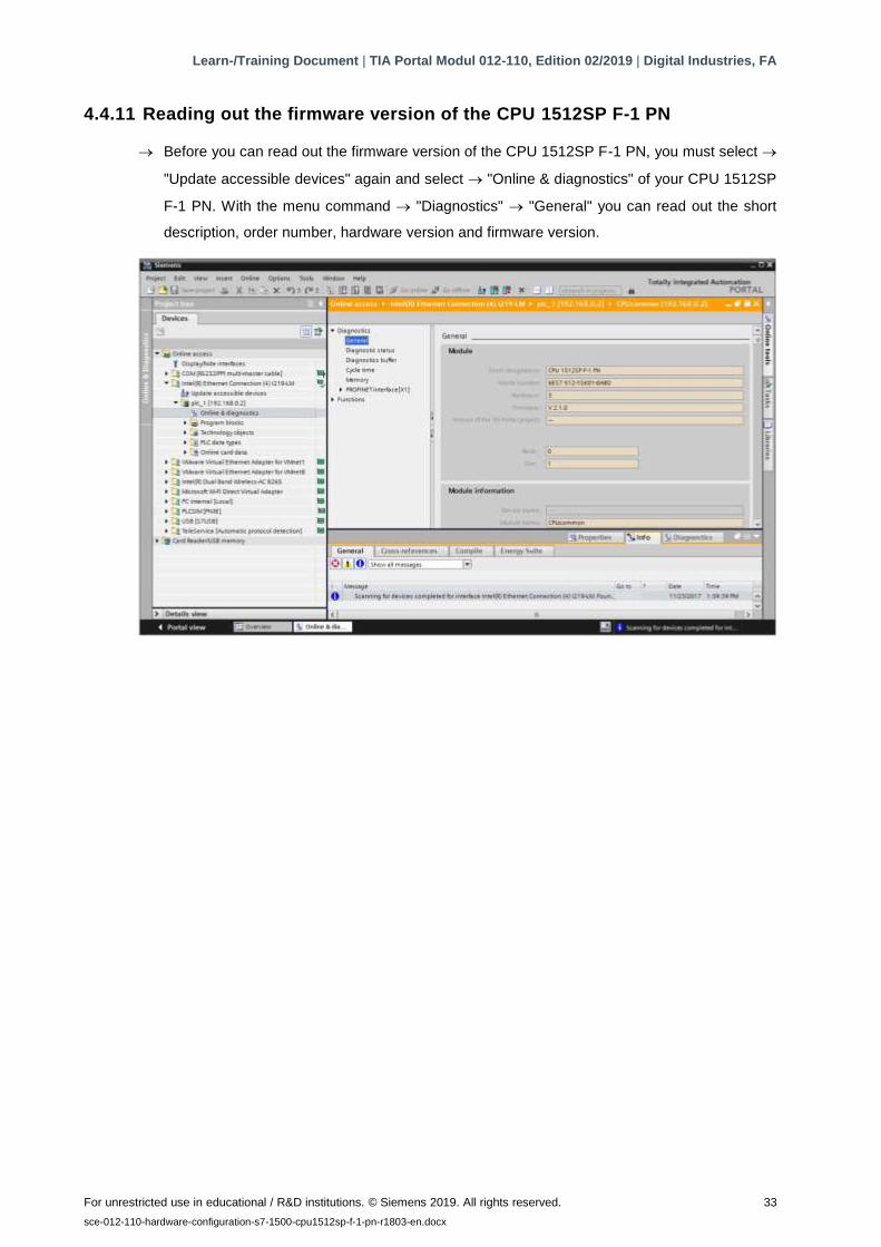
4.4.11 Reading out the firmware version of the CPU 1512SP F-1 PN
→ Before you can read out the firmware version of the CPU 1512SP F-1 PN, you must select →
"Update accessible devices" again and select → "Online & diagnostics" of your CPU 1512SP
F-1 PN. With the menu command → "Diagnostics" → "General" you can read out the short
description, order number, hardware version and firmware version.

Learn-/Training Document | TIA Portal Modul 012-110, Edition 02/2019 | Digital Industries, FA
For unrestricted use in educational / R&D institutions. © Siemens 2019. All rights reserved. 34
sce-012-110-hardware-configuration-s7-1500-cpu1512sp-f-1-pn-r1803-en.docx
5 Task
Create a project and configure the following modules of your hardware that correspond to the
trainer package SIMATIC CPU 1512SP F-1 PN with software.
– 1x CPU 1512SP F-1 PN for ET 200SP, central processing unit with 300 KB work memory for
program and 1 MB work memory for data, 1 interface, PROFINET IRT with 3-port switch, 48
ns bit performance, memory card (order number: 6ES7512-1SK01-0AB0)
– 2x DI 8x24VDC/0.5A HF (order number: 6ES7131-6BF00-0CA0)
– 2x DQ 8x24VDC/0.5A HF (order number: 6ES7132-6BF00-0CA0)
– 1x server module (order number: 6ES7 193-6PA00-0AA0)
6 Planning
Because a new system is involved, a new project must be created.
The hardware is already specified for this project with the SIMATIC CPU 1512SP F-1 PN with
software trainer package. For this reason, no selection has to be made. Instead, the listed modules
of the trainer package only have to be inserted in the project. In ensure the correct modules are
inserted, the order numbers from the task should be checked one more time directly on the
mounted devices.
It is customary to start with the CPU and then insert the signal modules in the associated slots.
See Table 1.
For the configuration, the Ethernet interface must be set for the CPU and the address ranges of
the digital inputs and outputs must be adapted.
Module Order number Slot Address range
CPU 1512SP F-1 PN 6ES7512-1SK01-0AB0 1
DI 8x24VDC/0.5A HF 6ES7131-6BF00-0CA0 2 DI 0
DI 8x24VDC/0.5A HF 6ES7131-6BF00-0CA0 3 DI 1
DQ 8x24VDC/0.5A HF 6ES7132-6BF00-0CA0 4 DQ 0
DQ 8x24VDC/0.5A HF 6ES7132-6BF00-0CA0 5 DQ 1
Server module 6ES7 193-6PA00-0AA0 6
Table 1: Overview of planned configuration
To complete the configuration, the HW configuration must be compiled and downloaded.
Configuration errors can be detected during compilation and incorrect modules can be detected
when the controller is started (only possible when configured hardware is present and identical).
The checked project must be saved.
Learn-/Training Document | TIA Portal Modul 012-110, Edition 02/2019 | Digital Industries, FA
For unrestricted use in educational / R&D institutions. © Siemens 2019. All rights reserved. 35
sce-012-110-hardware-configuration-s7-1500-cpu1512sp-f-1-pn-r1803-en.docx
7 Structured step-by-step instructions
You can find instructions on how to perform planning below. If you already have a good
understanding of everything, it is sufficient to focus on the numbered steps. Otherwise, simply
follow the steps of the instructions illustrated below.
7.1 Creating a new project
→ Double-click the icon for the Totally Integrated Automation Portal.
(→ TIA Portal V14)
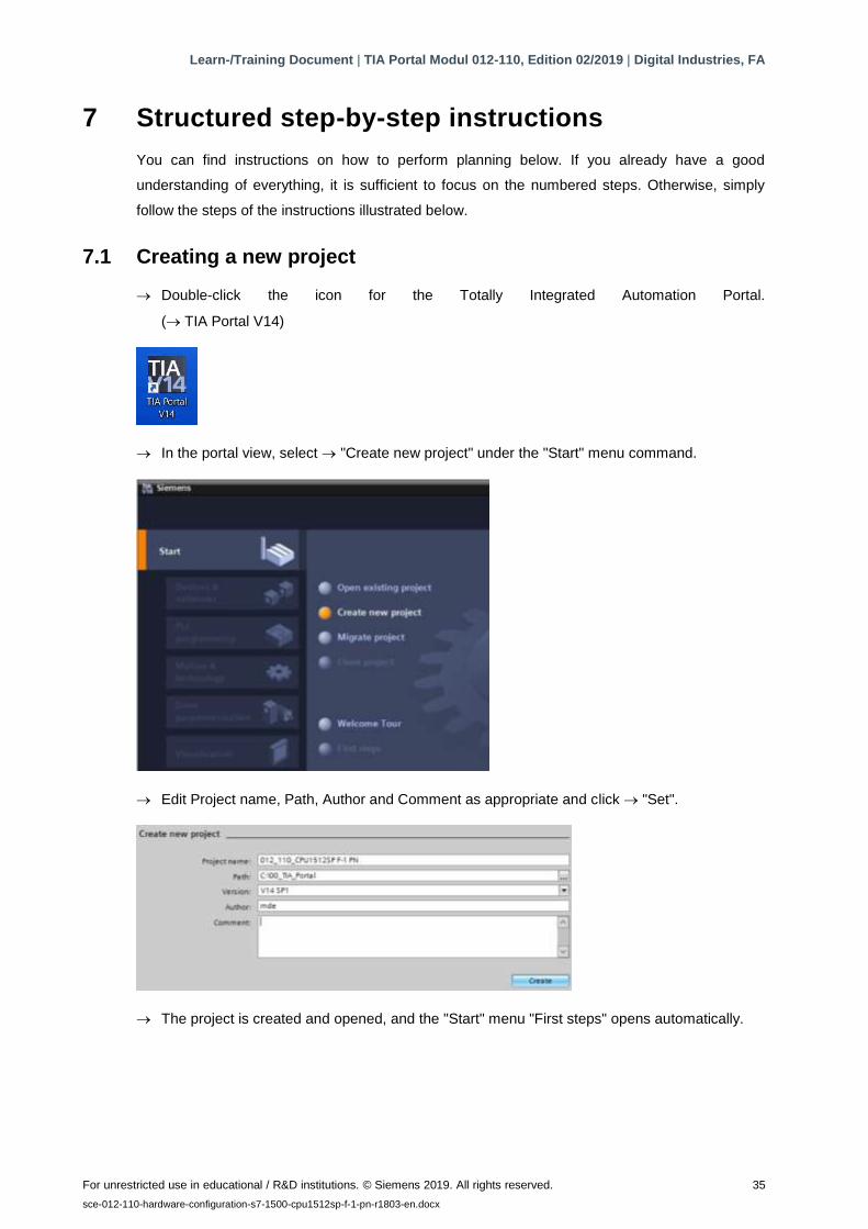
→ In the portal view, select → "Create new project" under the "Start" menu command.
→ Edit Project name, Path, Author and Comment as appropriate and click → "Set".
→ The project is created and opened, and the "Start" menu "First steps" opens automatically.
Learn-/Training Document | TIA Portal Modul 012-110, Edition 02/2019 | Digital Industries, FA
For unrestricted use in educational / R&D institutions. © Siemens 2019. All rights reserved. 36
sce-012-110-hardware-configuration-s7-1500-cpu1512sp-f-1-pn-r1803-en.docx
7.2 Inserting the CPU 1512SP F-1 PN
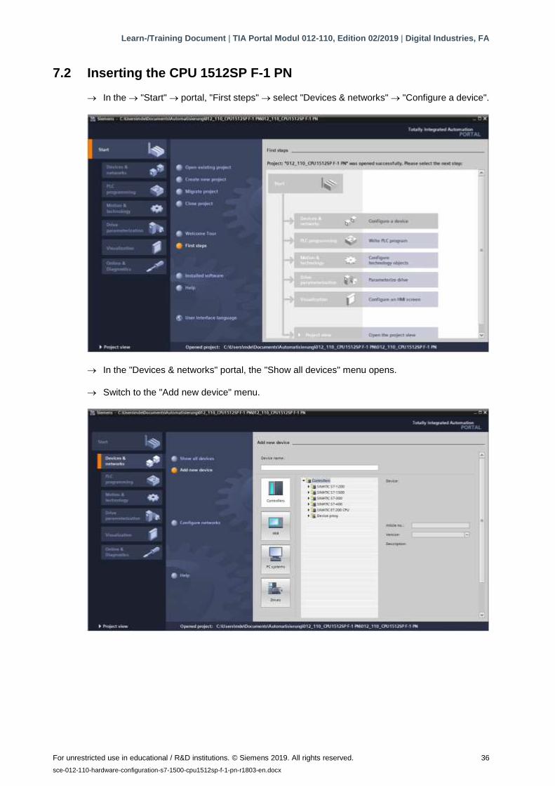
→ In the → "Start" → portal, "First steps" → select "Devices & networks" → "Configure a device".
→ In the "Devices & networks" portal, the "Show all devices" menu opens.
→ Switch to the "Add new device" menu.
Learn-/Training Document | TIA Portal Modul 012-110, Edition 02/2019 | Digital Industries, FA
For unrestricted use in educational / R&D institutions. © Siemens 2019. All rights reserved. 37
sce-012-110-hardware-configuration-s7-1500-cpu1512sp-f-1-pn-r1803-en.docx
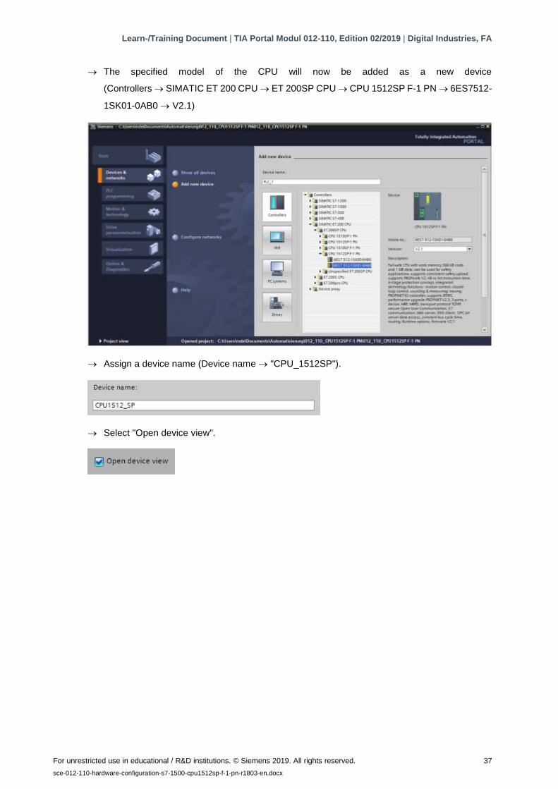
→ The specified model of the CPU will now be added as a new device
(Controllers → SIMATIC ET 200 CPU → ET 200SP CPU → CPU 1512SP F-1 PN → 6ES7512-
1SK01-0AB0 → V2.1)
→ Assign a device name (Device name → "CPU_1512SP").
→ Select "Open device view".
Learn-/Training Document | TIA Portal Modul 012-110, Edition 02/2019 | Digital Industries, FA
For unrestricted use in educational / R&D institutions. © Siemens 2019. All rights reserved. 38
sce-012-110-hardware-configuration-s7-1500-cpu1512sp-f-1-pn-r1803-en.docx
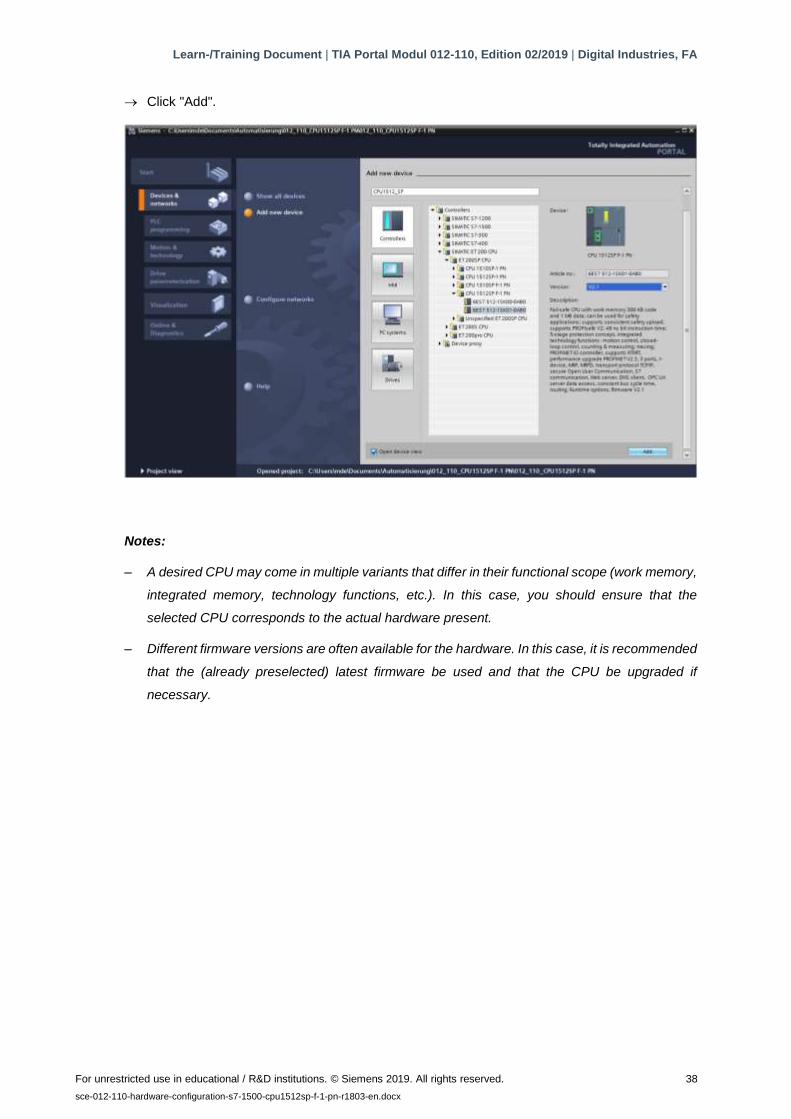
→ Click "Add".
Notes:
– A desired CPU may come in multiple variants that differ in their functional scope (work memory,
integrated memory, technology functions, etc.). In this case, you should ensure that the
selected CPU corresponds to the actual hardware present.
– Different firmware versions are often available for the hardware. In this case, it is recommended
that the (already preselected) latest firmware be used and that the CPU be upgraded if
necessary.
Learn-/Training Document | TIA Portal Modul 012-110, Edition 02/2019 | Digital Industries, FA
For unrestricted use in educational / R&D institutions. © Siemens 2019. All rights reserved. 39
sce-012-110-hardware-configuration-s7-1500-cpu1512sp-f-1-pn-r1803-en.docx
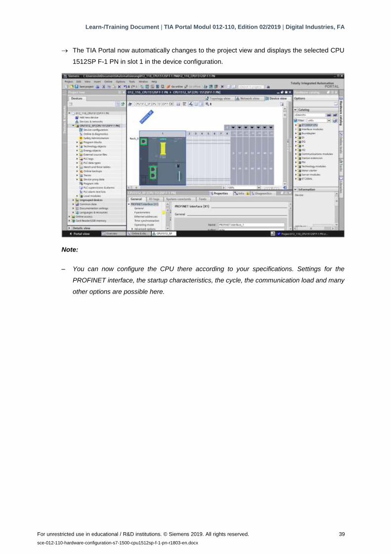
→ The TIA Portal now automatically changes to the project view and displays the selected CPU
1512SP F-1 PN in slot 1 in the device configuration.
Note:
– You can now configure the CPU there according to your specifications. Settings for the
PROFINET interface, the startup characteristics, the cycle, the communication load and many
other options are possible here.
Learn-/Training Document | TIA Portal Modul 012-110, Edition 02/2019 | Digital Industries, FA
For unrestricted use in educational / R&D institutions. © Siemens 2019. All rights reserved. 40
sce-012-110-hardware-configuration-s7-1500-cpu1512sp-f-1-pn-r1803-en.docx
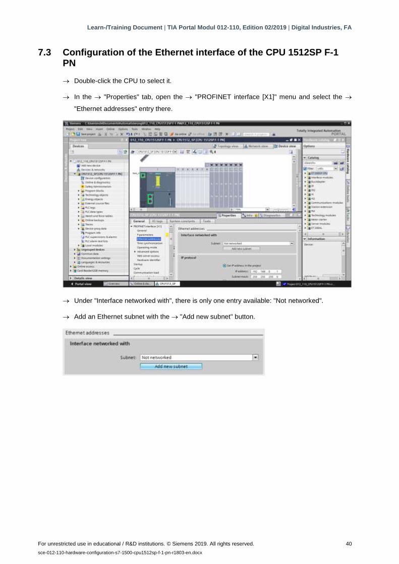
7.3 Configuration of the Ethernet interface of the CPU 1512SP F-1 PN
→ Double-click the CPU to select it.
→ In the → "Properties" tab, open the → "PROFINET interface [X1]" menu and select the →
"Ethernet addresses" entry there.
→ Under "Interface networked with", there is only one entry available: "Not networked".
→ Add an Ethernet subnet with the → "Add new subnet" button.

Learn-/Training Document | TIA Portal Modul 012-110, Edition 02/2019 | Digital Industries, FA
For unrestricted use in educational / R&D institutions. © Siemens 2019. All rights reserved. 41
sce-012-110-hardware-configuration-s7-1500-cpu1512sp-f-1-pn-r1803-en.docx
→ Keep the preset "IP address" and "Subnet mask" here.
7.4 Configuration of fail-safe operation of the CPU 1512SP F-1 PN
→ Change to the → "F-activation" item of the → "Fail-safe" menu and select → "Disable F-
activation" there.
→ Answer the question "Do you want to continue?" with → "Yes".
Learn-/Training Document | TIA Portal Modul 012-110, Edition 02/2019 | Digital Industries, FA
For unrestricted use in educational / R&D institutions. © Siemens 2019. All rights reserved. 42
sce-012-110-hardware-configuration-s7-1500-cpu1512sp-f-1-pn-r1803-en.docx
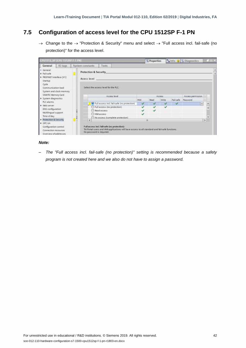
7.5 Configuration of access level for the CPU 1512SP F-1 PN
→ Change to the → "Protection & Security" menu and select → "Full access incl. fail-safe (no
protection)" for the access level.
Note:
– The "Full access incl. fail-safe (no protection)" setting is recommended because a safety
program is not created here and we also do not have to assign a password.

Learn-/Training Document | TIA Portal Modul 012-110, Edition 02/2019 | Digital Industries, FA
For unrestricted use in educational / R&D institutions. © Siemens 2019. All rights reserved. 43
sce-012-110-hardware-configuration-s7-1500-cpu1512sp-f-1-pn-r1803-en.docx
7.6 Inserting the digital input modules DI 8x24VDC HF
Select the correct module in the hardware catalog (→ Hardware catalog → Catalog → DI → DI
8x24VDC HF (order number 6ES7131-6BF00-0CA0) → Version: V2.0)

Learn-/Training Document | TIA Portal Modul 012-110, Edition 02/2019 | Digital Industries, FA
For unrestricted use in educational / R&D institutions. © Siemens 2019. All rights reserved. 44
sce-012-110-hardware-configuration-s7-1500-cpu1512sp-f-1-pn-r1803-en.docx
→ Insert the two digital input modules by dragging them into slots 2 and 3.
Note:
– For selection of the digital input module, you can simply enter the order number in the Search
field and click the "Search down" icon. The hardware catalog is opened at the right place.
Note:
– When you double-click a module in the Hardware catalog, it is inserted at the next available
suitable slot.
Learn-/Training Document | TIA Portal Modul 012-110, Edition 02/2019 | Digital Industries, FA
For unrestricted use in educational / R&D institutions. © Siemens 2019. All rights reserved. 45
sce-012-110-hardware-configuration-s7-1500-cpu1512sp-f-1-pn-r1803-en.docx
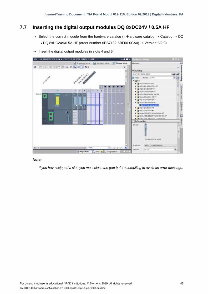
7.7 Inserting the digital output modules DQ 8xDC24V / 0.5A HF
→ Select the correct module from the hardware catalog (→Hardware catalog → Catalog → DQ
→ DQ 8xDC24V/0.5A HF (order number 6ES7132-6BF00-0CA0) → Version: V2.0)
→ Insert the digital output modules in slots 4 and 5.
Note:
– If you have skipped a slot, you must close the gap before compiling to avoid an error message.
Learn-/Training Document | TIA Portal Modul 012-110, Edition 02/2019 | Digital Industries, FA
For unrestricted use in educational / R&D institutions. © Siemens 2019. All rights reserved. 46
sce-012-110-hardware-configuration-s7-1500-cpu1512sp-f-1-pn-r1803-en.docx
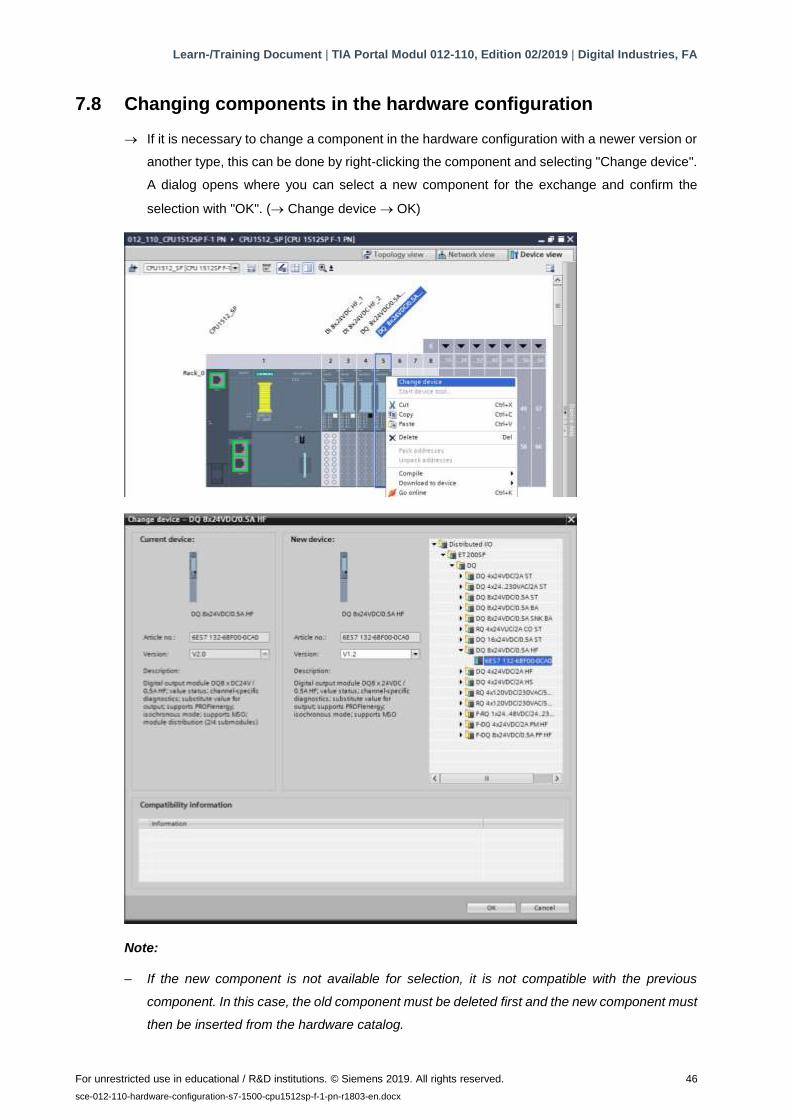
7.8 Changing components in the hardware configuration
→ If it is necessary to change a component in the hardware configuration with a newer version or
another type, this can be done by right-clicking the component and selecting "Change device".
A dialog opens where you can select a new component for the exchange and confirm the
selection with "OK". (→ Change device → OK)
Note:
– If the new component is not available for selection, it is not compatible with the previous
component. In this case, the old component must be deleted first and the new component must
then be inserted from the hardware catalog.

Learn-/Training Document | TIA Portal Modul 012-110, Edition 02/2019 | Digital Industries, FA
For unrestricted use in educational / R&D institutions. © Siemens 2019. All rights reserved. 47
sce-012-110-hardware-configuration-s7-1500-cpu1512sp-f-1-pn-r1803-en.docx
7.9 Inserting the server module
→ Select the correct server module with the correct order number and version from the hardware
catalog. Insert the server module in slot 5. (→ Hardware catalog → Server module → 6ES7
193-6PA00-0AA0 → Version: V1.1)
Note:
– If you forget to insert the server module, it will be created automatically when the device
configuration is compiled.
Learn-/Training Document | TIA Portal Modul 012-110, Edition 02/2019 | Digital Industries, FA
For unrestricted use in educational / R&D institutions. © Siemens 2019. All rights reserved. 48
sce-012-110-hardware-configuration-s7-1500-cpu1512sp-f-1-pn-r1803-en.docx
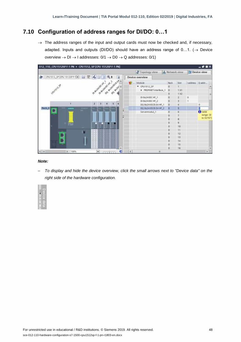
7.10 Configuration of address ranges for DI/DO: 0…1
→ The address ranges of the input and output cards must now be checked and, if necessary,
adapted. Inputs and outputs (DI/DO) should have an address range of 0…1. (→ Device
overview → DI → I addresses: 0/1 → D0 → Q addresses: 0/1)
Note:
– To display and hide the device overview, click the small arrows next to "Device data" on the
right side of the hardware configuration.

Learn-/Training Document | TIA Portal Modul 012-110, Edition 02/2019 | Digital Industries, FA
For unrestricted use in educational / R&D institutions. © Siemens 2019. All rights reserved. 49
sce-012-110-hardware-configuration-s7-1500-cpu1512sp-f-1-pn-r1803-en.docx
7.11 Configuration of the potential groups of the BaseUnits
→ To change the potential group of a BaseUnit, select the associated module and open the
"Potential group" section in the general properties. (Slot 3 → Properties → General → Potential
group)
→ Select the "Enable new potential group (light BaseUnit)" option.
Learn-/Training Document | TIA Portal Modul 012-110, Edition 02/2019 | Digital Industries, FA
For unrestricted use in educational / R&D institutions. © Siemens 2019. All rights reserved. 50
sce-012-110-hardware-configuration-s7-1500-cpu1512sp-f-1-pn-r1803-en.docx
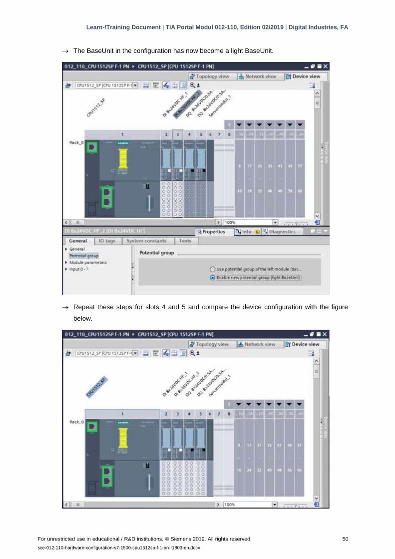
→ The BaseUnit in the configuration has now become a light BaseUnit.
→ Repeat these steps for slots 4 and 5 and compare the device configuration with the figure
below.
Learn-/Training Document | TIA Portal Modul 012-110, Edition 02/2019 | Digital Industries, FA
For unrestricted use in educational / R&D institutions. © Siemens 2019. All rights reserved. 51
sce-012-110-hardware-configuration-s7-1500-cpu1512sp-f-1-pn-r1803-en.docx
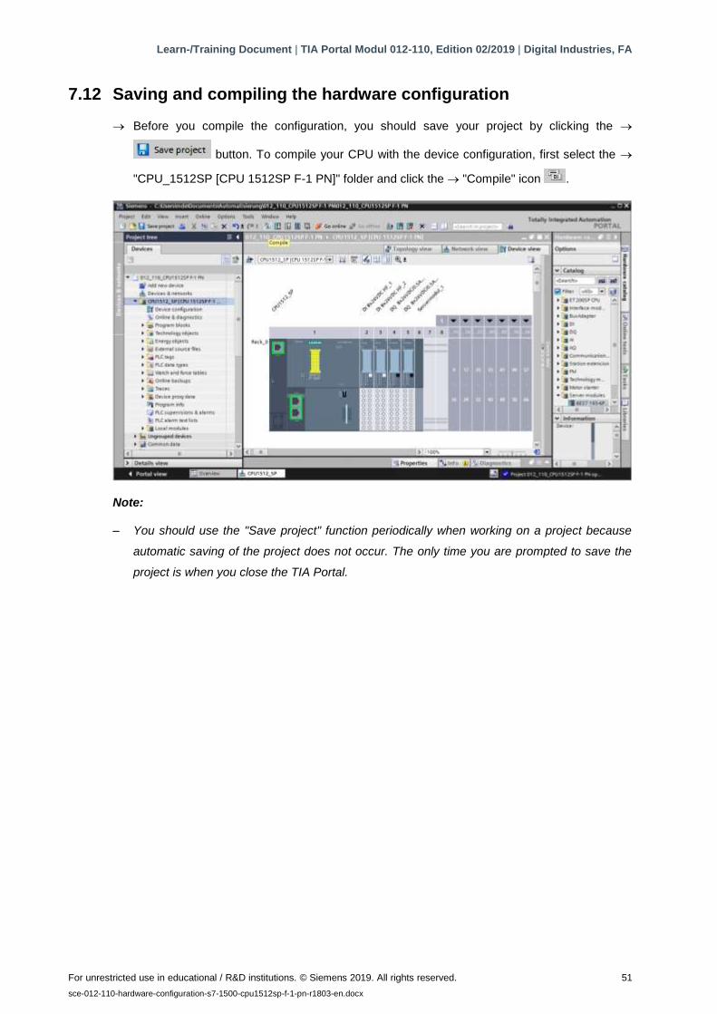
7.12 Saving and compiling the hardware configuration
→ Before you compile the configuration, you should save your project by clicking the →
button. To compile your CPU with the device configuration, first select the →
"CPU_1512SP [CPU 1512SP F-1 PN]" folder and click the → "Compile" icon .
Note:
– You should use the "Save project" function periodically when working on a project because
automatic saving of the project does not occur. The only time you are prompted to save the
project is when you close the TIA Portal.
Learn-/Training Document | TIA Portal Modul 012-110, Edition 02/2019 | Digital Industries, FA
For unrestricted use in educational / R&D institutions. © Siemens 2019. All rights reserved. 52
sce-012-110-hardware-configuration-s7-1500-cpu1512sp-f-1-pn-r1803-en.docx
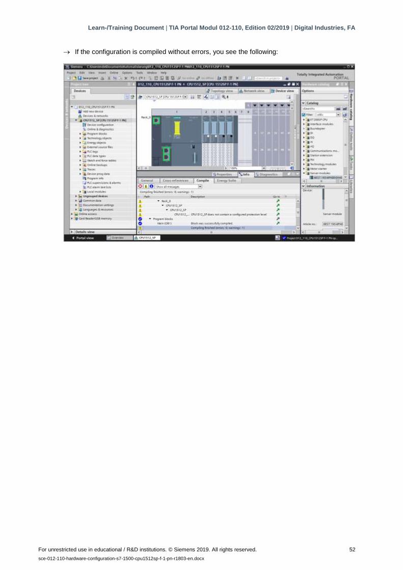
→ If the configuration is compiled without errors, you see the following:

Learn-/Training Document | TIA Portal Modul 012-110, Edition 02/2019 | Digital Industries, FA
For unrestricted use in educational / R&D institutions. © Siemens 2019. All rights reserved. 53
sce-012-110-hardware-configuration-s7-1500-cpu1512sp-f-1-pn-r1803-en.docx
7.13 Downloading the hardware configuration to the device
→ To download your complete CPU to the device, select the → "CPU_1512SP [CPU 1512SP F-
1 PN]" folder again and click the "Download to device" icon →.
→ The manager for configuration of connection properties (Extended download) opens.
Learn-/Training Document | TIA Portal Modul 012-110, Edition 02/2019 | Digital Industries, FA
For unrestricted use in educational / R&D institutions. © Siemens 2019. All rights reserved. 54
sce-012-110-hardware-configuration-s7-1500-cpu1512sp-f-1-pn-r1803-en.docx
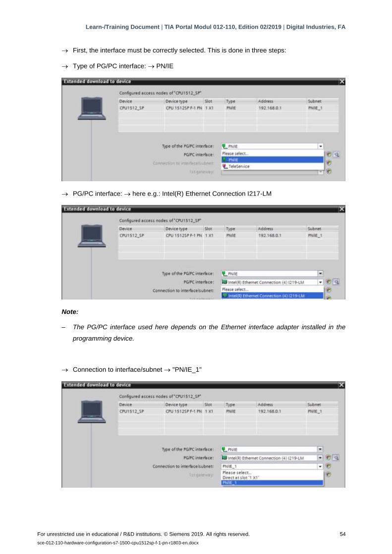
→ First, the interface must be correctly selected. This is done in three steps:
→ Type of PG/PC interface: → PN/IE
→ PG/PC interface: → here e.g.: Intel(R) Ethernet Connection I217-LM
Note:
– The PG/PC interface used here depends on the Ethernet interface adapter installed in the
programming device.
→ Connection to interface/subnet → "PN/IE_1"
Learn-/Training Document | TIA Portal Modul 012-110, Edition 02/2019 | Digital Industries, FA
For unrestricted use in educational / R&D institutions. © Siemens 2019. All rights reserved. 55
sce-012-110-hardware-configuration-s7-1500-cpu1512sp-f-1-pn-r1803-en.docx
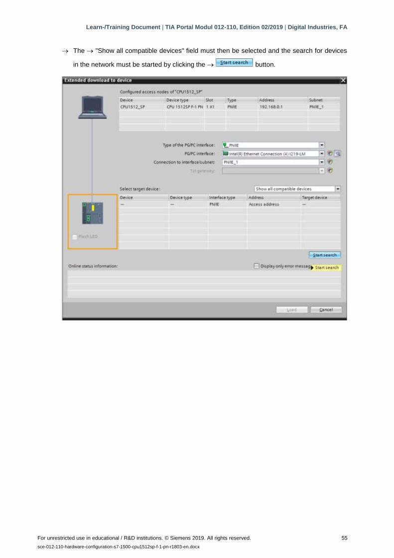
→ The → "Show all compatible devices" field must then be selected and the search for devices
in the network must be started by clicking the → button.
Learn-/Training Document | TIA Portal Modul 012-110, Edition 02/2019 | Digital Industries, FA
For unrestricted use in educational / R&D institutions. © Siemens 2019. All rights reserved. 56
sce-012-110-hardware-configuration-s7-1500-cpu1512sp-f-1-pn-r1803-en.docx
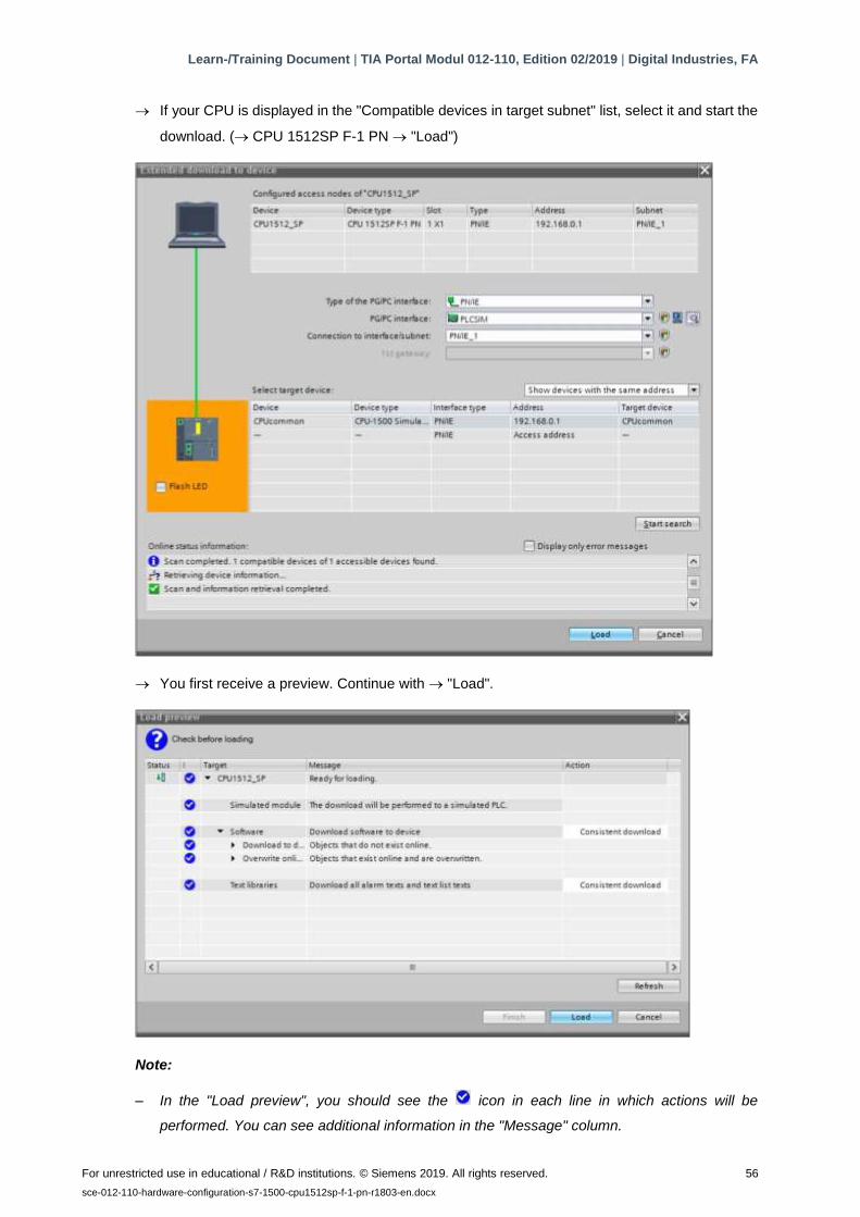
→ If your CPU is displayed in the "Compatible devices in target subnet" list, select it and start the
download. (→ CPU 1512SP F-1 PN → "Load")
→ You first receive a preview. Continue with → "Load".
Note:
– In the "Load preview", you should see the icon in each line in which actions will be
performed. You can see additional information in the "Message" column.
Learn-/Training Document | TIA Portal Modul 012-110, Edition 02/2019 | Digital Industries, FA
For unrestricted use in educational / R&D institutions. © Siemens 2019. All rights reserved. 57
sce-012-110-hardware-configuration-s7-1500-cpu1512sp-f-1-pn-r1803-en.docx
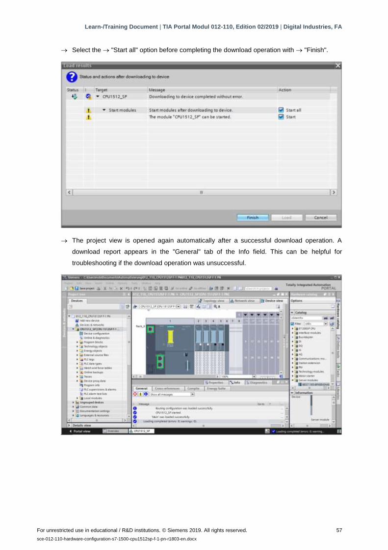
→ Select the → "Start all" option before completing the download operation with → "Finish".
→ The project view is opened again automatically after a successful download operation. A
download report appears in the "General" tab of the Info field. This can be helpful for
troubleshooting if the download operation was unsuccessful.
Learn-/Training Document | TIA Portal Modul 012-110, Edition 02/2019 | Digital Industries, FA
For unrestricted use in educational / R&D institutions. © Siemens 2019. All rights reserved. 58
sce-012-110-hardware-configuration-s7-1500-cpu1512sp-f-1-pn-r1803-en.docx
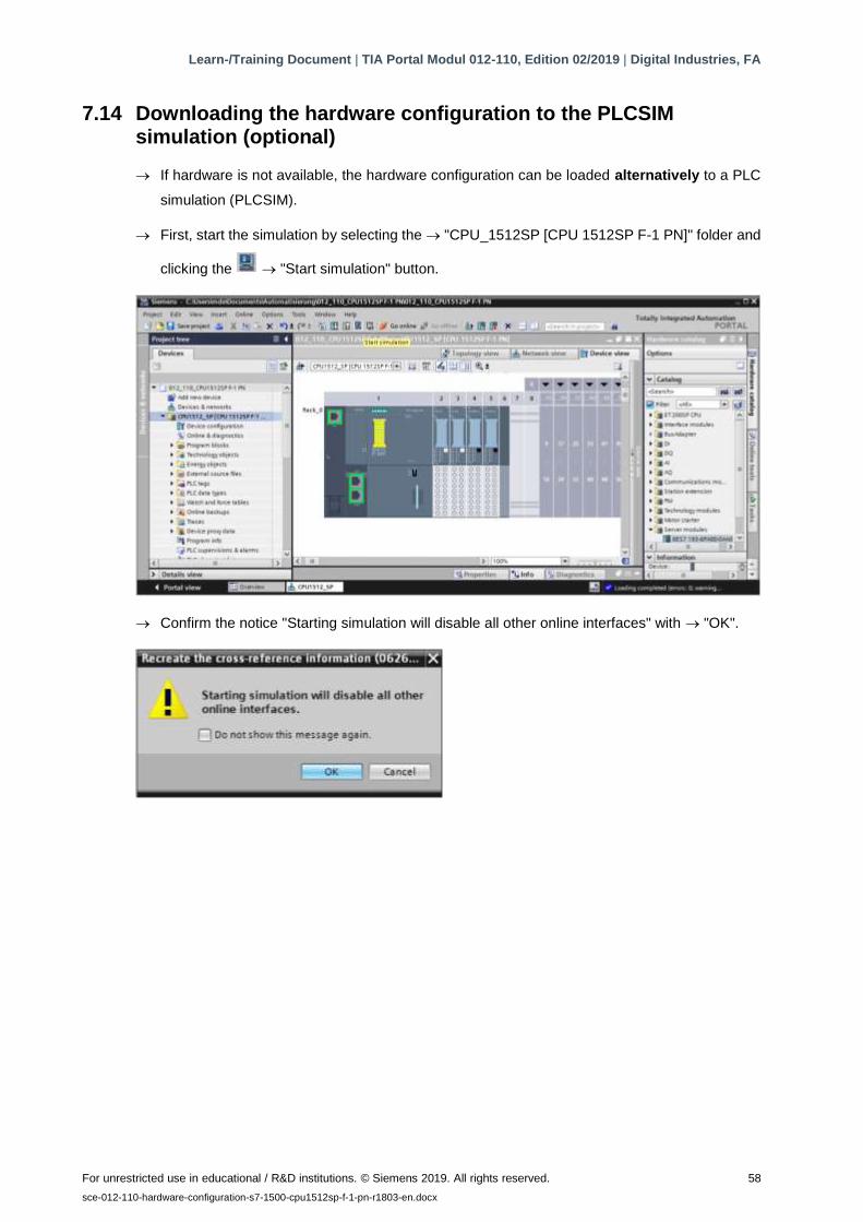
7.14 Downloading the hardware configuration to the PLCSIM simulation (optional)
→ If hardware is not available, the hardware configuration can be loaded alternatively to a PLC
simulation (PLCSIM).
→ First, start the simulation by selecting the → "CPU_1512SP [CPU 1512SP F-1 PN]" folder and
clicking the → "Start simulation" button.
→ Confirm the notice "Starting simulation will disable all other online interfaces" with → "OK".

Learn-/Training Document | TIA Portal Modul 012-110, Edition 02/2019 | Digital Industries, FA
For unrestricted use in educational / R&D institutions. © Siemens 2019. All rights reserved. 59
sce-012-110-hardware-configuration-s7-1500-cpu1512sp-f-1-pn-r1803-en.docx
→ The "PLCSIM" software is started in a separate window in the compact view.
→ The manager for configuration of connection properties (Extended download) opens shortly
thereafter.
Learn-/Training Document | TIA Portal Modul 012-110, Edition 02/2019 | Digital Industries, FA
For unrestricted use in educational / R&D institutions. © Siemens 2019. All rights reserved. 60
sce-012-110-hardware-configuration-s7-1500-cpu1512sp-f-1-pn-r1803-en.docx
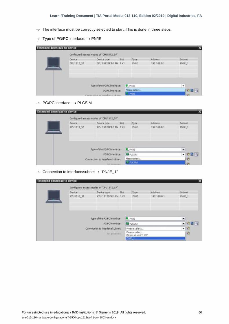
→ The interface must be correctly selected to start. This is done in three steps:
→ Type of PG/PC interface: → PN/IE
→ PG/PC interface: → PLCSIM
→ Connection to interface/subnet → "PN/IE_1"

Learn-/Training Document | TIA Portal Modul 012-110, Edition 02/2019 | Digital Industries, FA
For unrestricted use in educational / R&D institutions. © Siemens 2019. All rights reserved. 61
sce-012-110-hardware-configuration-s7-1500-cpu1512sp-f-1-pn-r1803-en.docx
→ The → "Show all compatible devices" field must then be selected and the search for devices
in the network must be started by clicking the → button.

Learn-/Training Document | TIA Portal Modul 012-110, Edition 02/2019 | Digital Industries, FA
For unrestricted use in educational / R&D institutions. © Siemens 2019. All rights reserved. 62
sce-012-110-hardware-configuration-s7-1500-cpu1512sp-f-1-pn-r1803-en.docx
→ If your panel is displayed in the "Compatible devices in target subnet" list, it must be selected
before the download can be started. (→ "CPU-1500 Simulation" → "Load")
→ You first receive a preview. Continue with → "Load".
Note:
– In the "Load preview", you should see the icon in each line in which actions will be
performed. You can see additional information in the "Message" column.
Learn-/Training Document | TIA Portal Modul 012-110, Edition 02/2019 | Digital Industries, FA
For unrestricted use in educational / R&D institutions. © Siemens 2019. All rights reserved. 63
sce-012-110-hardware-configuration-s7-1500-cpu1512sp-f-1-pn-r1803-en.docx
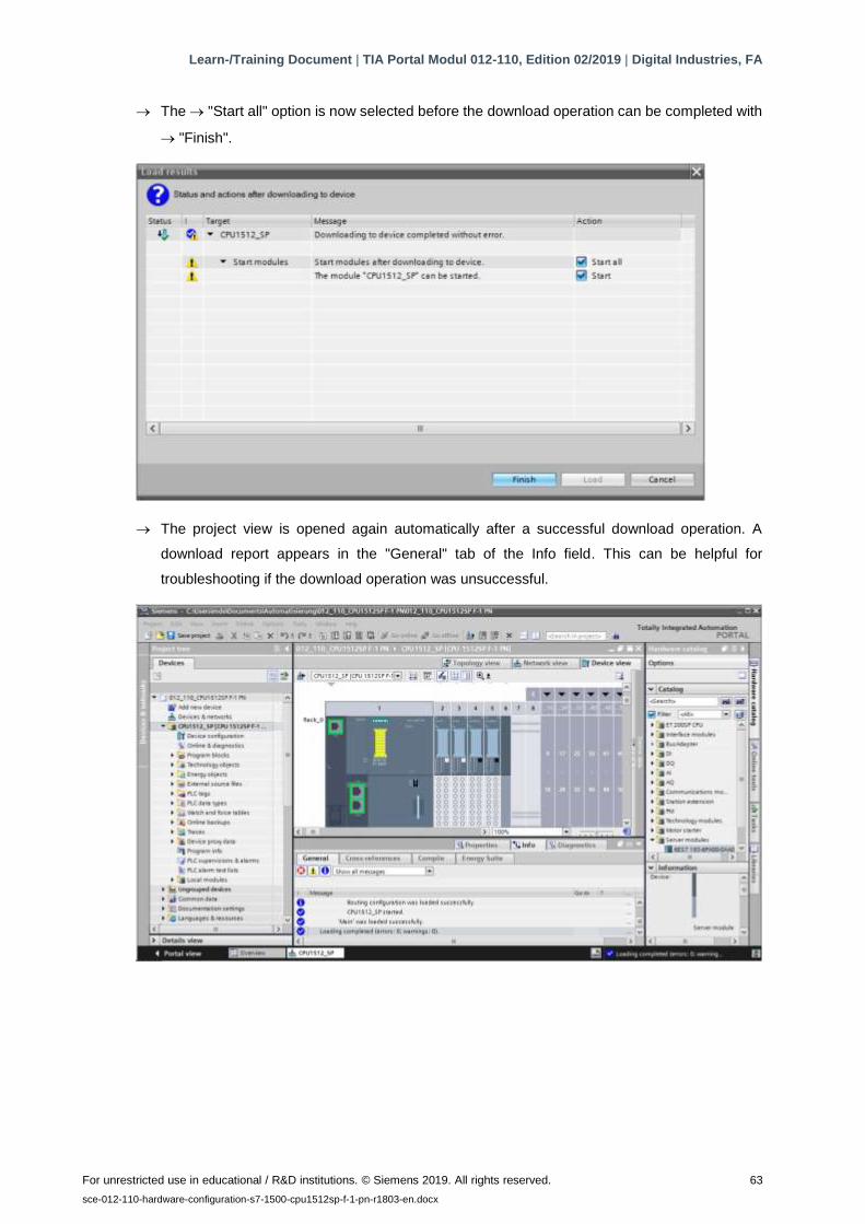
→ The → "Start all" option is now selected before the download operation can be completed with
→ "Finish".
→ The project view is opened again automatically after a successful download operation. A
download report appears in the "General" tab of the Info field. This can be helpful for
troubleshooting if the download operation was unsuccessful.
Learn-/Training Document | TIA Portal Modul 012-110, Edition 02/2019 | Digital Industries, FA
For unrestricted use in educational / R&D institutions. © Siemens 2019. All rights reserved. 64
sce-012-110-hardware-configuration-s7-1500-cpu1512sp-f-1-pn-r1803-en.docx
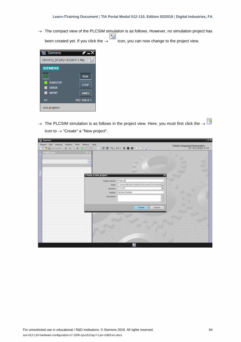
→ The compact view of the PLCSIM simulation is as follows. However, no simulation project has
been created yet. If you click the → icon, you can now change to the project view.
→ The PLCSIM simulation is as follows in the project view. Here, you must first click the →
icon to → "Create" a "New project".

Learn-/Training Document | TIA Portal Modul 012-110, Edition 02/2019 | Digital Industries, FA
For unrestricted use in educational / R&D institutions. © Siemens 2019. All rights reserved. 65
sce-012-110-hardware-configuration-s7-1500-cpu1512sp-f-1-pn-r1803-en.docx
→ If you double-click the → "Device configuration", you can view the downloaded configuration in
the project view. You can also set input signals and monitor output signals later for testing the
programs. You can change back to the compact view of the simulation by clicking the →
icon in the menu bar.
Note:
– You cannot detect hardware configuration errors because a hardware simulation is involved.
Learn-/Training Document | TIA Portal Modul 012-110, Edition 02/2019 | Digital Industries, FA
For unrestricted use in educational / R&D institutions. © Siemens 2019. All rights reserved. 66
sce-012-110-hardware-configuration-s7-1500-cpu1512sp-f-1-pn-r1803-en.docx
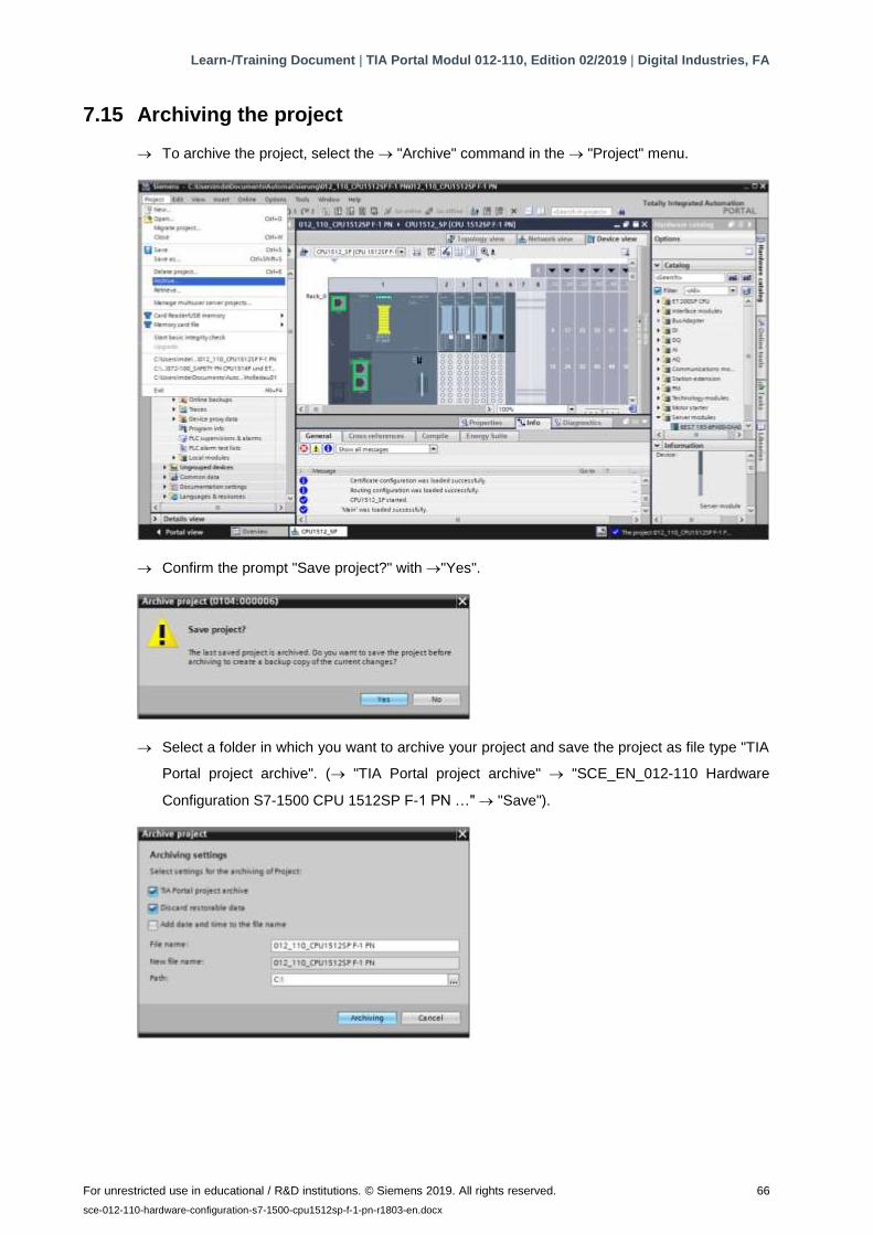
7.15 Archiving the project
→ To archive the project, select the → "Archive" command in the → "Project" menu.
→ Confirm the prompt "Save project?" with →"Yes".
→ Select a folder in which you want to archive your project and save the project as file type "TIA
Portal project archive". (→ "TIA Portal project archive" → "SCE_EN_012-110 Hardware
Configuration S7-1500 CPU 1512SP F-1 PN …" → "Save").
Learn-/Training Document | TIA Portal Modul 012-110, Edition 02/2019 | Digital Industries, FA
For unrestricted use in educational / R&D institutions. © Siemens 2019. All rights reserved. 67
sce-012-110-hardware-configuration-s7-1500-cpu1512sp-f-1-pn-r1803-en.docx
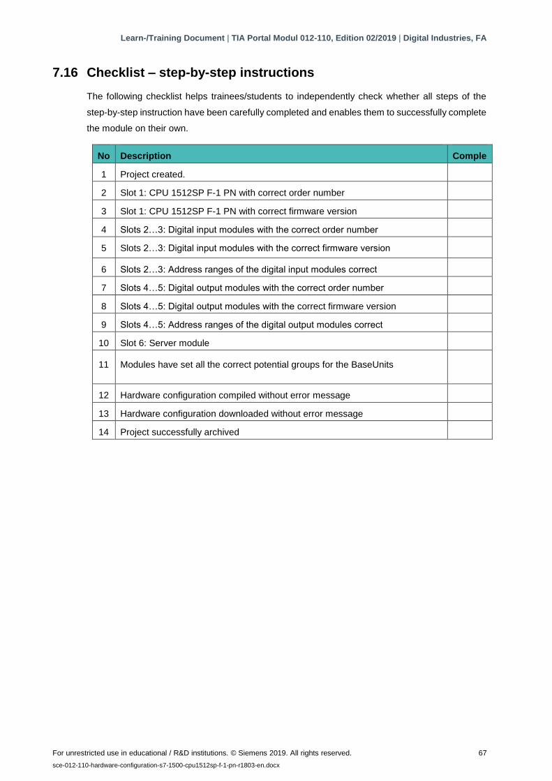
7.16 Checklist – step-by-step instructions
The following checklist helps trainees/students to independently check whether all steps of the
step-by-step instruction have been carefully completed and enables them to successfully complete
the module on their own.
No
.
Description Comple
ted 1 Project created.
2 Slot 1: CPU 1512SP F-1 PN with correct order number
3 Slot 1: CPU 1512SP F-1 PN with correct firmware version
4 Slots 2…3: Digital input modules with the correct order number
5 Slots 2…3: Digital input modules with the correct firmware version
6 Slots 2…3: Address ranges of the digital input modules correct
7 Slots 4…5: Digital output modules with the correct order number
8 Slots 4…5: Digital output modules with the correct firmware version
9 Slots 4…5: Address ranges of the digital output modules correct
10 Slot 6: Server module
11 Modules have set all the correct potential groups for the BaseUnits
12 Hardware configuration compiled without error message
13 Hardware configuration downloaded without error message
14 Project successfully archived
Learn-/Training Document | TIA Portal Modul 012-110, Edition 02/2019 | Digital Industries, FA
For unrestricted use in educational / R&D institutions. © Siemens 2019. All rights reserved. 68
sce-012-110-hardware-configuration-s7-1500-cpu1512sp-f-1-pn-r1803-en.docx
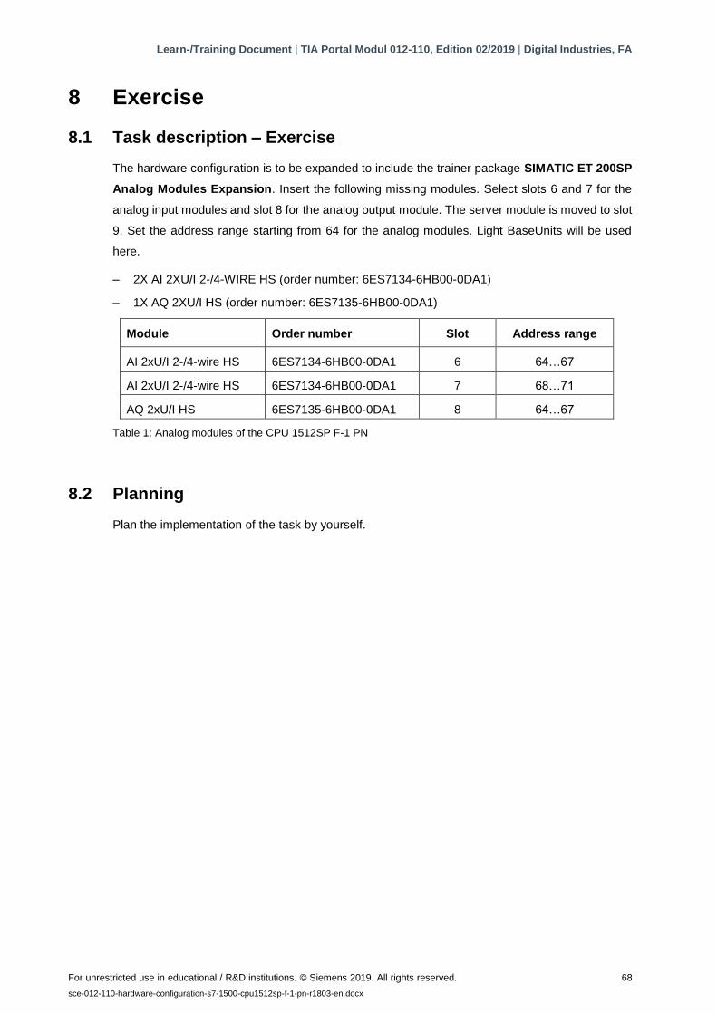
8 Exercise
8.1 Task description – Exercise
The hardware configuration is to be expanded to include the trainer package SIMATIC ET 200SP
Analog Modules Expansion. Insert the following missing modules. Select slots 6 and 7 for the
analog input modules and slot 8 for the analog output module. The server module is moved to slot
9. Set the address range starting from 64 for the analog modules. Light BaseUnits will be used
here.
– 2X AI 2XU/I 2-/4-WIRE HS (order number: 6ES7134-6HB00-0DA1)
– 1X AQ 2XU/I HS (order number: 6ES7135-6HB00-0DA1)
Module Order number Slot Address range
AI 2xU/I 2-/4-wire HS 6ES7134-6HB00-0DA1 6 64…67
AI 2xU/I 2-/4-wire HS 6ES7134-6HB00-0DA1 7 68…71
AQ 2xU/I HS 6ES7135-6HB00-0DA1 8 64…67
Table 1: Analog modules of the CPU 1512SP F-1 PN
8.2 Planning
Plan the implementation of the task by yourself.

Learn-/Training Document | TIA Portal Modul 012-110, Edition 02/2019 | Digital Industries, FA
For unrestricted use in educational / R&D institutions. © Siemens 2019. All rights reserved. 69
sce-012-110-hardware-configuration-s7-1500-cpu1512sp-f-1-pn-r1803-en.docx
8.3 Checklist – Exercise
The following checklist helps trainees/students to independently check whether all steps of the
exercise have been carefully completed and enables them to successfully complete the module on
their own.
No. Description Completed
1 Slots 6…7: Analog input modules with the correct order number
2 Slots 6…7: Analog input modules with the correct firmware version
3 Slots 6…7: Address ranges of the analog input modules correct
4 Slot 8: Analog output module with the correct order number
5 Slot 8: Analog output module with the correct firmware version
6 Slot 8: Address range of the analog output module correct
7 Slot 9: Server module
8 Modules have set all the correct potential groups for the BaseUnits
9 Hardware configuration compiled without error message
10 Hardware configuration downloaded without error message
11 Project successfully archived

Learn-/Training Document | TIA Portal Modul 012-110, Edition 02/2019 | Digital Industries, FA
For unrestricted use in educational / R&D institutions. © Siemens 2019. All rights reserved. 70
sce-012-110-hardware-configuration-s7-1500-cpu1512sp-f-1-pn-r1803-en.docx
9 Additional information
More information for further practice and consolidation is available as orientation, for example:
Getting Started, videos, tutorials, apps, manuals, programming guidelines and trial software /
firmware, under the following link:
siemens.com/sce/s7-1500
Preview "Additional information"
Learn-/Training Document | TIA Portal Modul 012-110, Edition 02/2019 | Digital Industries, FA
For unrestricted use in educational / R&D institutions. © Siemens 2019. All rights reserved. 71
sce-012-110-hardware-configuration-s7-1500-cpu1512sp-f-1-pn-r1803-en.docx
Further Information
Siemens Automation Cooperates with Education siemens.com/sce
SCE Learn-/Training Documents
siemens.com/sce/documents
SCE Trainer Packages
siemens.com/sce/tp
SCE Contact Partners
siemens.com/sce/contact
Digital Enterprise
siemens.com/digital-enterprise
Industrie 4.0
siemens.com/future-of-manufacturing
Totally Integrated Automation (TIA)
siemens.com/tia
TIA Portal
siemens.com/tia-portal
SIMATIC Controller
siemens.com/controller
SIMATIC Technical Documentation
siemens.com/simatic-docu
Industry Online Support
support.industry.siemens.com
Product catalogue and online ordering system Industry Mall
mall.industry.siemens.com
Siemens
Digital Industries
P.O. Box 4848
90026 Nuremberg
Germany
Subject to change and errors
© Siemens 2019
siemens.com/sce