Embed Size (px)
DESCRIPTION
Specimen Size Effects in the Determination of Nuclear Grade Graphite Thermal Diffusivity. ASTM D02F000 Symposium on Graphite Testing for Nuclear Applications: the Significance of Test Specimen Volume and Geometry and the Statistical Significance of Test Specimen Population - PowerPoint PPT Presentation
Citation preview
ww
w.in
l.gov
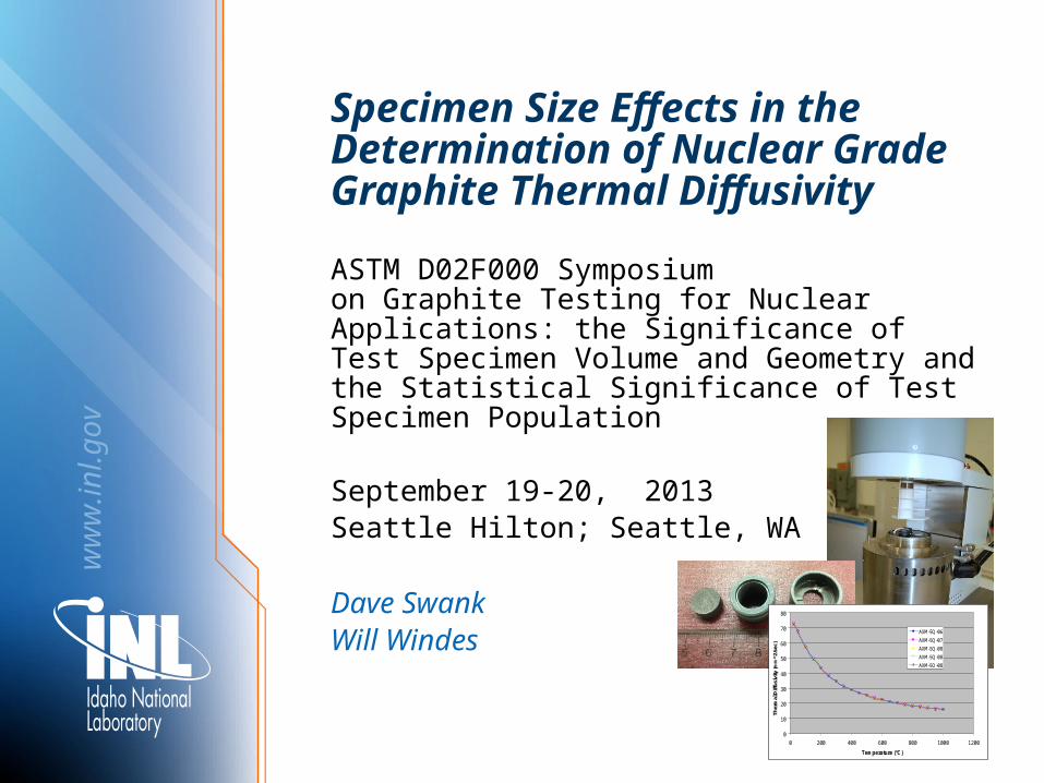
Specimen Size Effects in the Determination of Nuclear Grade Graphite Thermal Diffusivity
ASTM D02F000 Symposium on Graphite Testing for Nuclear Applications: the Significance of Test Specimen Volume and Geometry and the Statistical Significance of Test Specimen Population
September 19-20, 2013 Seattle Hilton; Seattle, WA
Dave SwankWill Windes
0
10
20
30
40
50
60
70
80
0 200 400 600 800 1000 1200
Temperature (°C)
Ther
mal
Diff
usiv
ity (m
m^2
/sec
)
AXM-5Q-06
AXM-5Q-07
AXM-5Q-08
AXM-5Q-08
AXM-5Q-08
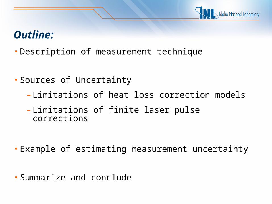
Outline:
• Description of measurement technique
• Sources of Uncertainty
– Limitations of heat loss correction models
– Limitations of finite laser pulse corrections
• Example of estimating measurement uncertainty
• Summarize and conclude
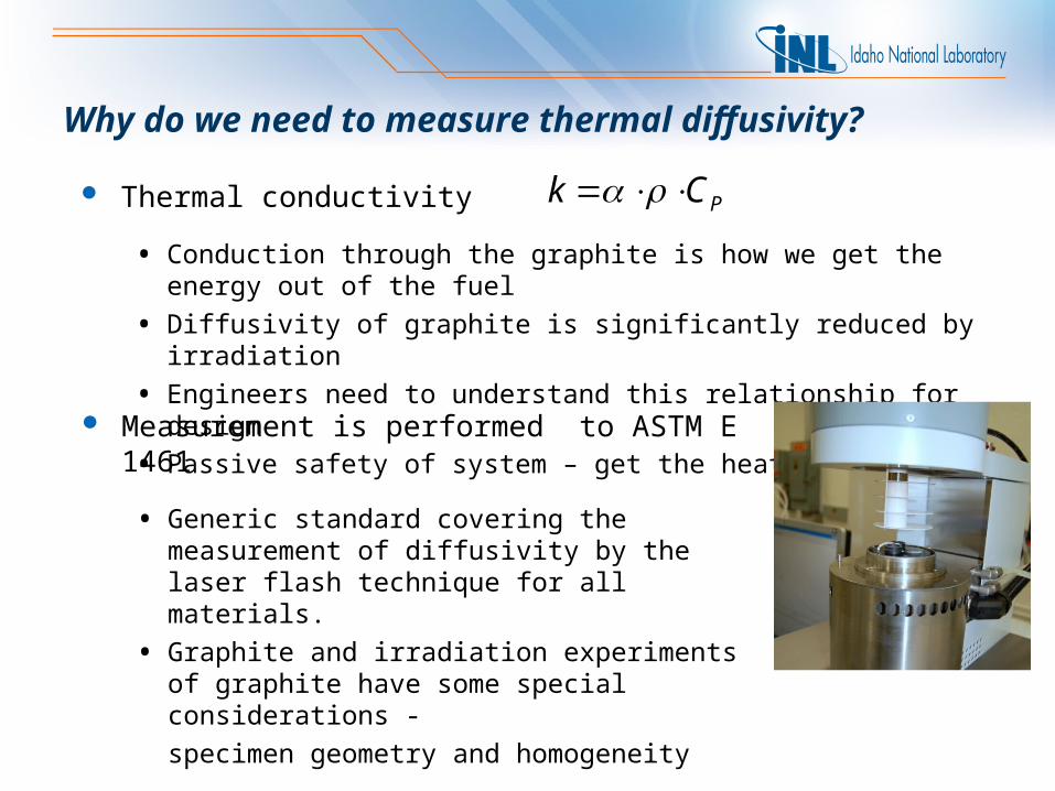
Why do we need to measure thermal diffusivity?
Thermal conductivity
• Conduction through the graphite is how we get the energy out of the fuel
• Diffusivity of graphite is significantly reduced by irradiation
• Engineers need to understand this relationship for design
• Passive safety of system – get the heat out
PCk
Measurement is performed to ASTM E 1461
• Generic standard covering the measurement of diffusivity by the laser flash technique for all materials.
• Graphite and irradiation experiments of graphite have some special considerations -
specimen geometry and homogeneity
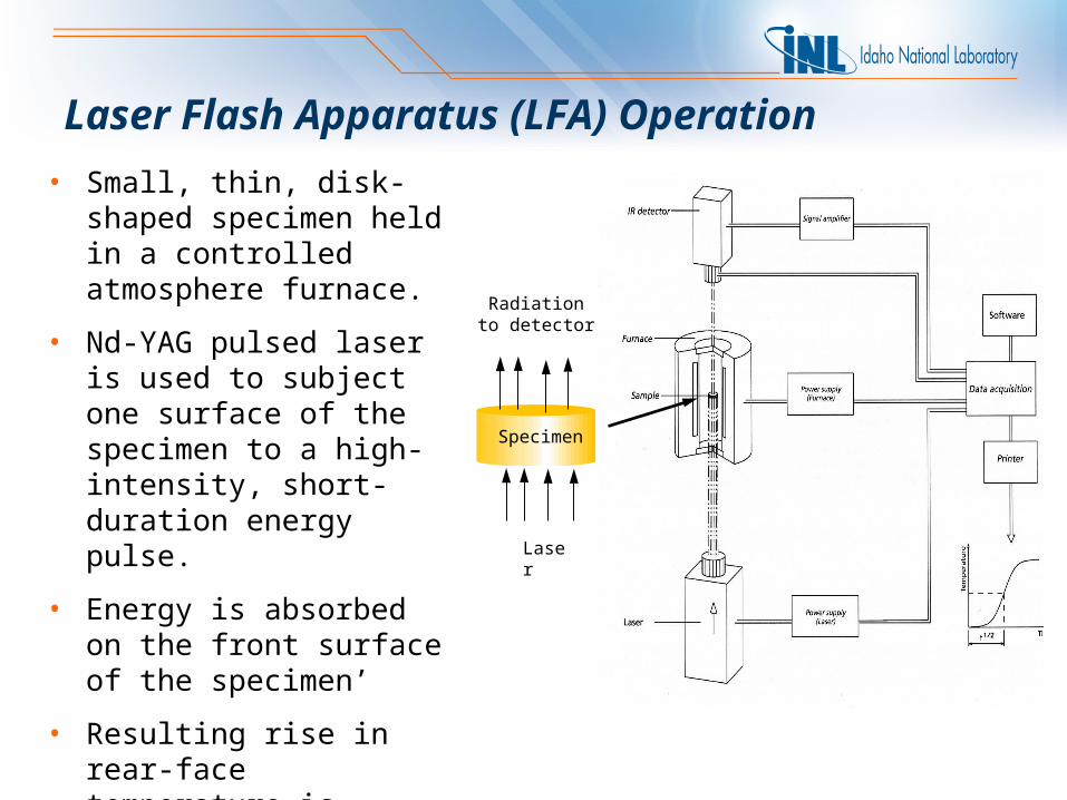
Laser Flash Apparatus (LFA) Operation
Radiation to detector
Laser
Specimen
• Small, thin, disk-shaped specimen held in a controlled atmosphere furnace.
• Nd-YAG pulsed laser is used to subject one surface of the specimen to a high-intensity, short-duration energy pulse.
• Energy is absorbed on the front surface of the specimen’
• Resulting rise in rear-face temperature is recorded with a sensitive IR detector.
Thermal Diffusivity
• One-dimensional heat flow
• No heat loss
• Homogenous specimen
• Uniform absorption of the laser energy
• Short pulse length of the laser compared to the heat transport times
Thermal Diffusivity for a Laser Flash Apparatus (LFA) solved analytically for adiabatic conditions by Parker et. al., 1961
2/1
21388.0t
L
Radiation to detector
Laser
SpecimenL
-100 -50 0 50 100 150 200 250
Time /ms
-0.5
0.0
0.5
1.0
1.5
2.0
2.5
3.0
3.5
4.0
Sig
nal/V
Detector Signal
Laser Pulse
t1/2
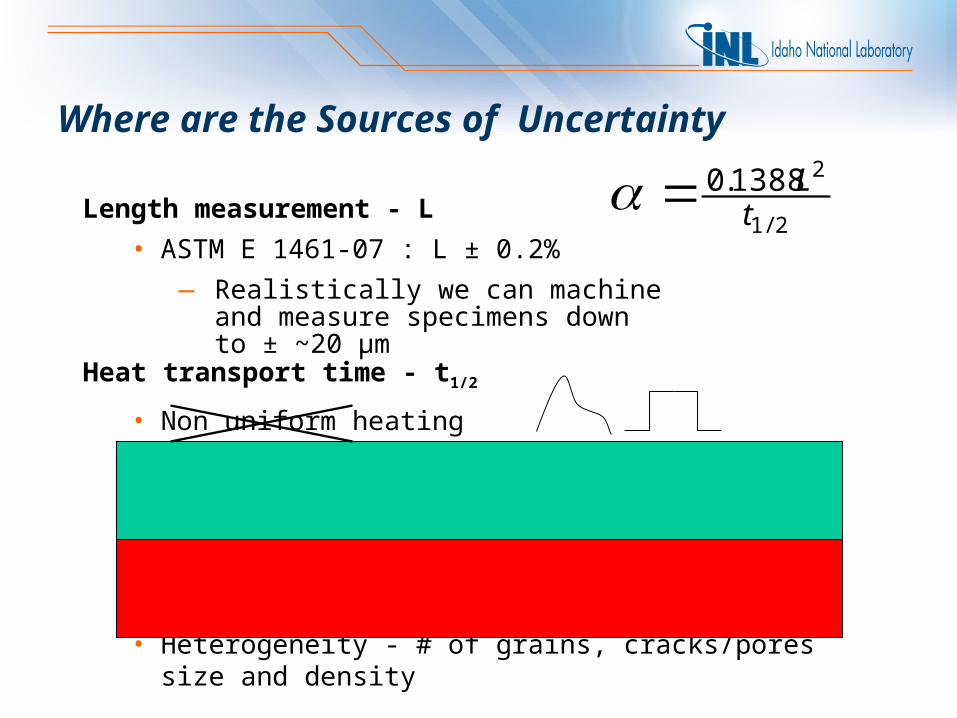
Heat transport time - t1/2
• Non uniform heating
• Multi directional conduction
• Heat Loss: Radiation, Conduction, Convection
• Finite laser pulse width
• Heterogeneity - # of grains, cracks/pores size and density
2/1
21388.0t
LWhere are the Sources of Uncertainty
Length measurement - L
• ASTM E 1461-07 : L ± 0.2%
— Realistically we can machine and measure specimens down to ± ~20 µm
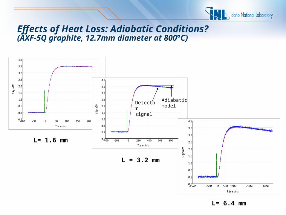
L= 1.6 mm
-100 -50 0 50 100 150 200 250
Time /ms
-0.5
0.0
0.5
1.0
1.5
2.0
2.5
3.0
3.5
4.0
Sig
nal/V
L = 3.2 mm
L= 6.4 mm
Effects of Heat Loss: Adiabatic Conditions? (AXF-5Q graphite, 12.7mm diameter at 800°C)
-400 -200 0 200 400 600 800 1000
Time /ms
-0.5
0.0
0.5
1.0
1.5
2.0
2.5
3.0
3.5
4.0
Sig
na
l/V
Detector signal
Adiabatic model
-1500 -500 0 500 1000 2000 3000
Time /ms
-0.5
0.0
0.5
1.0
1.5
2.0
2.5
3.0
3.5
4.0
Sig
nal/V
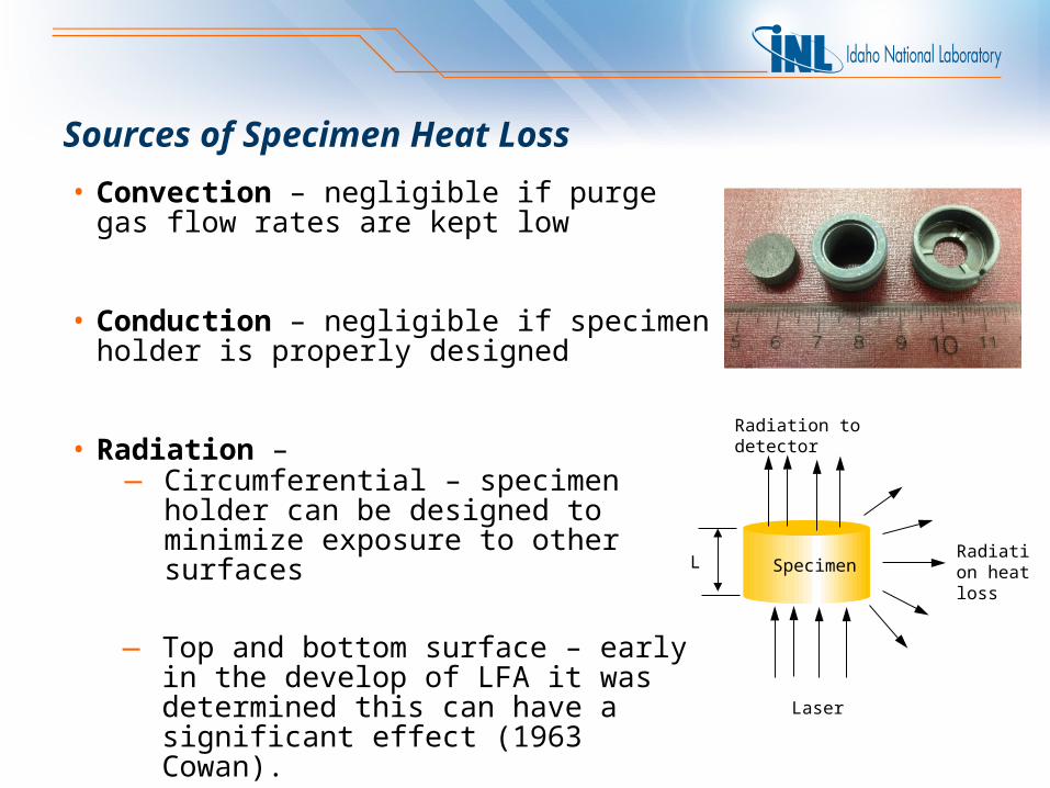
Sources of Specimen Heat Loss
• Convection – negligible if purge gas flow rates are kept low
• Conduction – negligible if specimen holder is properly designed
• Radiation –
— Top and bottom surface – early in the develop of LFA it was determined this can have a significant effect (1963 Cowan).
— Circumferential – specimen holder can be designed to minimize exposure to other surfaces
Radiation to detector
Radiation heat loss
Laser
SpecimenL
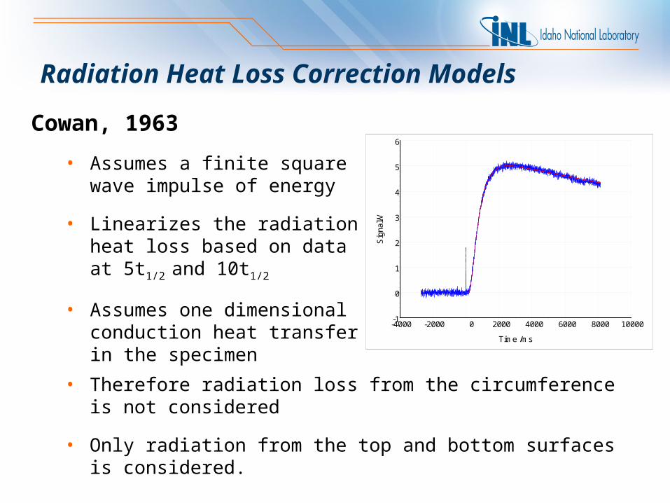
Radiation Heat Loss Correction Models
Cowan, 1963
• Assumes a finite square wave impulse of energy
• Linearizes the radiation heat loss based on data at 5t1/2 and 10t1/2
• Assumes one dimensional conduction heat transfer in the specimen
-4000 -2000 0 2000 4000 6000 8000 10000
Time /ms
-1
0
1
2
3
4
5
6
Sig
nal/V
• Therefore radiation loss from the circumference is not considered
• Only radiation from the top and bottom surfaces is considered.
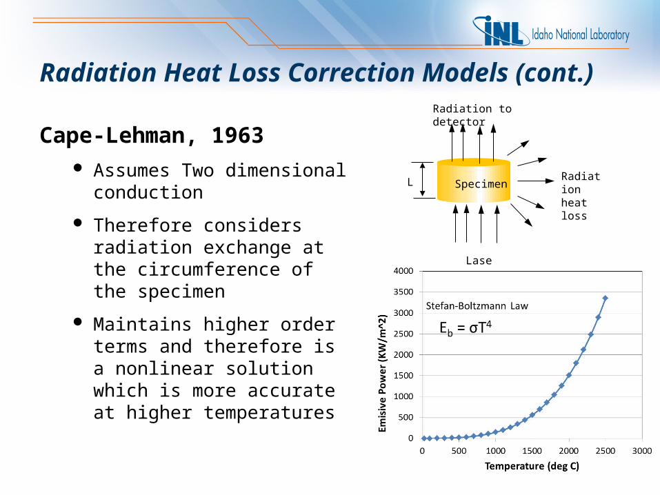
Cape-Lehman, 1963 Assumes Two dimensional
conduction
Therefore considers radiation exchange at the circumference of the specimen
Maintains higher order terms and therefore is a nonlinear solution which is more accurate at higher temperatures
Radiation to detector
Radiation heat loss
Laser
SpecimenL
Radiation Heat Loss Correction Models (cont.)
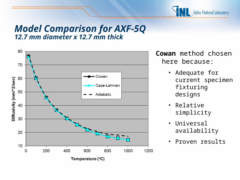
Model Comparison for AXF-5Q 12.7 mm diameter x 12.7 mm thick
Cowan method chosen here because:
• Adequate for current specimen fixturing designs
• Relative simplicity
• Universal availability
• Proven results
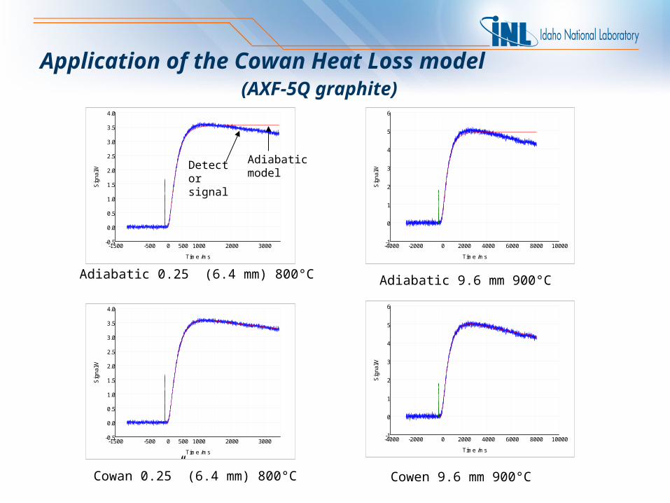
Application of the Cowan Heat Loss model (AXF-5Q graphite)
-1500 -500 0 500 1000 2000 3000
Time /ms
-0.5
0.0
0.5
1.0
1.5
2.0
2.5
3.0
3.5
4.0
Sig
nal/V
Cowan 0.25” (6.4 mm) 800°C
Adiabatic 0.25” (6.4 mm) 800°C
-4000 -2000 0 2000 4000 6000 8000 10000
Time /ms
-1
0
1
2
3
4
5
6
Sig
nal/V
-4000 -2000 0 2000 4000 6000 8000 10000
Time /ms
-1
0
1
2
3
4
5
6
Sig
nal/V
Cowen 9.6 mm 900°C
Adiabatic 9.6 mm 900°C
-1500 -500 0 500 1000 2000 3000
Time /ms
-0.5
0.0
0.5
1.0
1.5
2.0
2.5
3.0
3.5
4.0
Sig
nal/V
Detector signal
Adiabatic model
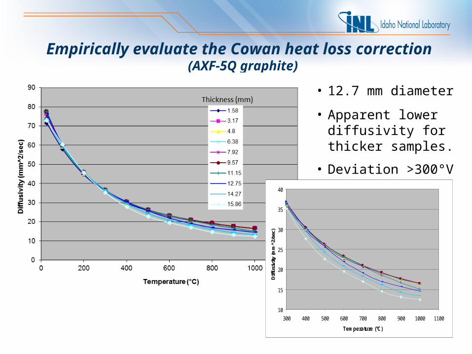
Empirically evaluate the Cowan heat loss correction (AXF-5Q graphite)
10
15
20
25
30
35
40
300 400 500 600 700 800 900 1000 1100
Temperature (°C)
Diff
usiv
ity (m
m^2
/sec
)
• 12.7 mm diameter
• Apparent lower diffusivity for thicker samples.
• Deviation >300°V
0
20
40
60
80
100
120
140
160
0 200 400 600 800 1000 1200
Temperature (°C)
Em
issi
ve P
ow
er (
kW/m
^2)
Stefan-Boltzmann Law Eb = σT4
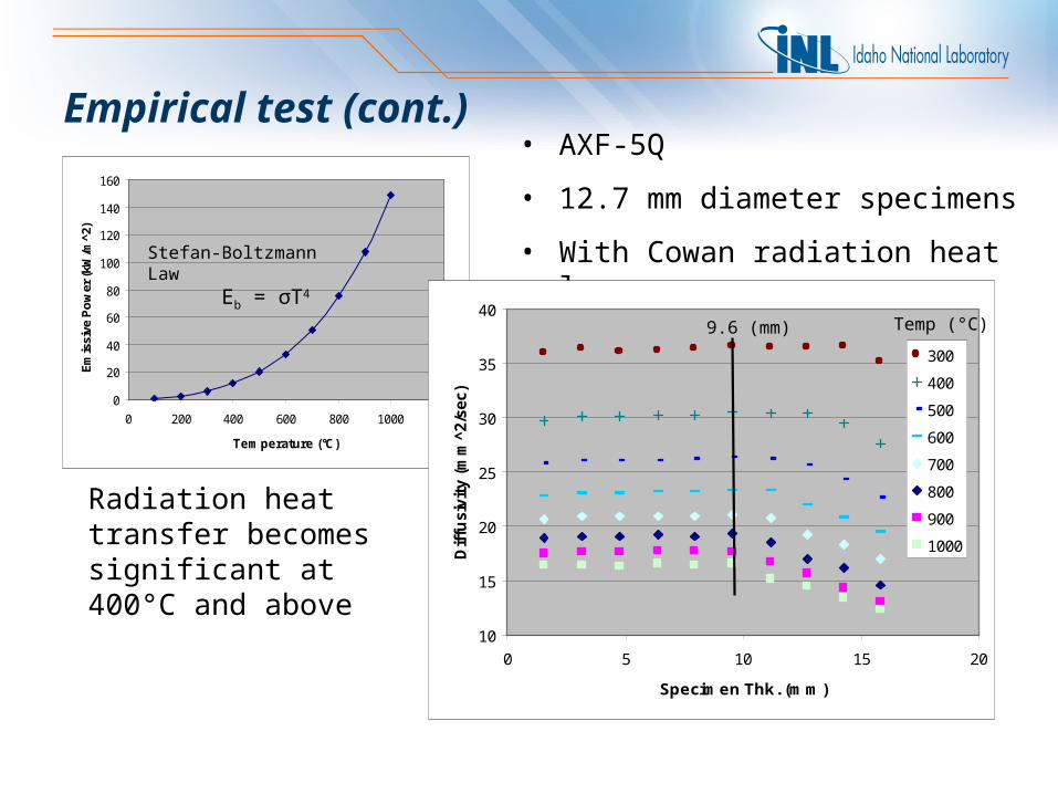
• AXF-5Q
• 12.7 mm diameter specimens
• With Cowan radiation heat loss
Radiation heat transfer becomes significant at 400°C and above
Empirical test (cont.)
10
15
20
25
30
35
40
0 5 10 15 20
Specimen Thk. (mm)
Dif
fusiv
ity
(mm
^2/s
ec)
300
400
500
600
700
800
900
1000
9.6 (mm) Temp (°C)
10
15
20
25
30
35
40
45
50
55
60
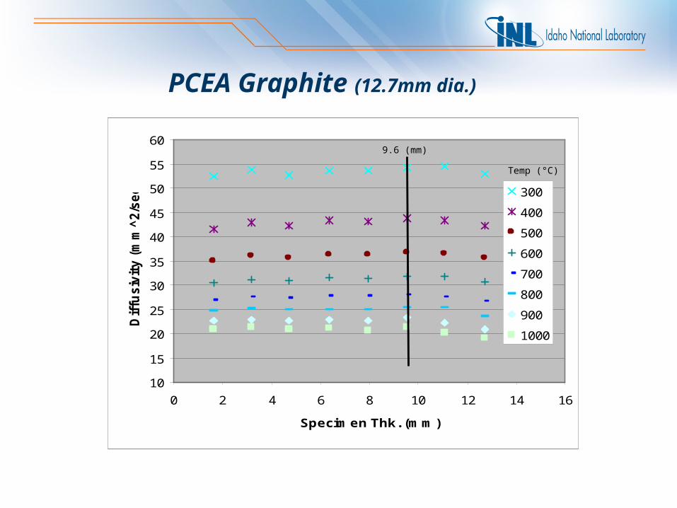
0 2 4 6 8 10 12 14 16
Specimen Thk. (mm)
Dif
fusiv
ity (
mm
^2/s
ec)
300
400
500
600
700
800
900
1000
9.6 (mm)
Temp (°C)
PCEA Graphite (12.7mm dia.)
10
15
20
25
30
35
40
45
50
55
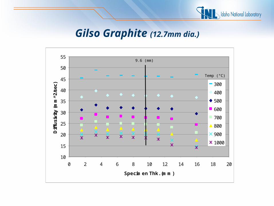
0 2 4 6 8 10 12 14 16 18 20
Specimen Thk. (mm)
Dif
fusi
vity
(m
m^2
/sec
) 300
400
500
600
700
800
900
1000
9.6 (mm)
Temp (°C)
Gilso Graphite (12.7mm dia.)
10
15
20
25
30
35
40
45
50
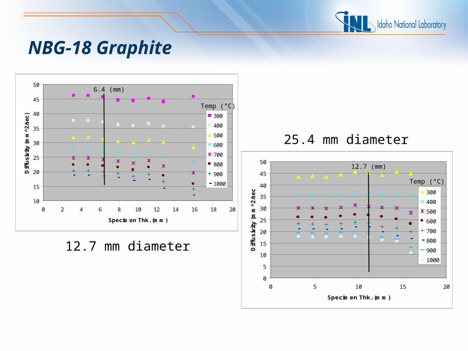
0 2 4 6 8 10 12 14 16 18 20
Specimen Thk. (mm)
Dif
fusi
vity
(m
m^2
/sec
) 300
400
500
600
700
800
900
1000
6.4 (mm)
Temp (°C)
0
5
10
15
20
25
30
35
40
45
50
0 5 10 15 20
Specimen Thk. (mm)
Dif
fusiv
ity (
mm
^2/s
ec)
300
400
500
600
700
800
900
1000
12.7 (mm)
Temp (°C)
NBG-18 Graphite
12.7 mm diameter
25.4 mm diameter
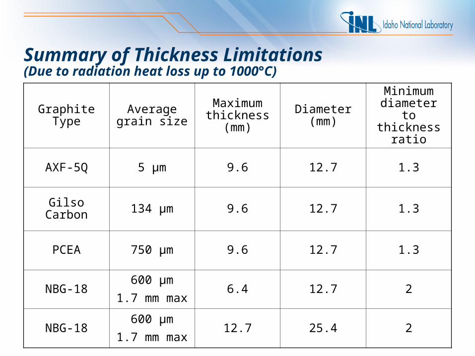
Summary of Thickness Limitations(Due to radiation heat loss up to 1000°C)
Graphite Type Average grain size
Maximum thickness
(mm)
Diameter (mm)
Minimum diameter to
thickness ratio
AXF-5Q 5 µm 9.6 12.7 1.3
Gilso Carbon 134 µm 9.6 12.7 1.3
PCEA 750 µm 9.6 12.7 1.3
NBG-18600 µm
1.7 mm max6.4 12.7 2
NBG-18600 µm
1.7 mm max12.7 25.4 2
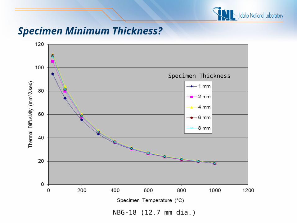
Specimen Minimum Thickness?
NBG-18 (12.7 mm dia.)
Specimen Thickness
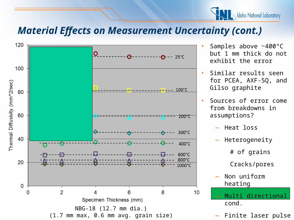
Material Effects on Measurement Uncertainty (cont.)
20%
• Samples above ~400°C but 1 mm thick do not exhibit the error
• Similar results seen for PCEA, AXF-5Q, and Gilso graphite
NBG-18 (12.7 mm dia.)(1.7 mm max, 0.6 mm avg. grain size)
• Sources of error come from breakdowns in assumptions?
— Heat loss
— Heterogeneity
# of grains
Cracks/pores
— Non uniform heating
— Multi directional cond.
— Finite laser pulse width
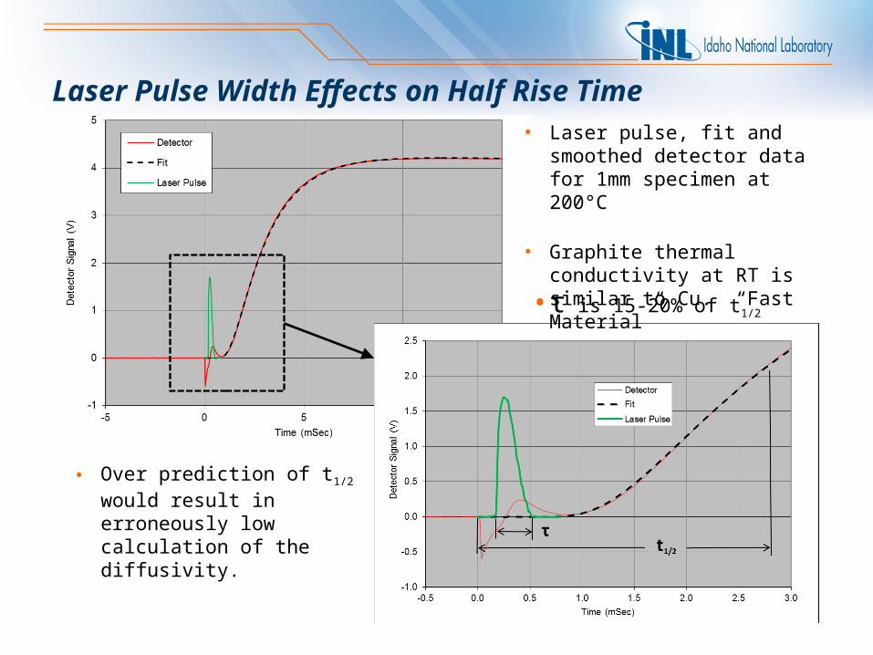
Laser Pulse Width Effects on Half Rise Time• Laser pulse, fit and smoothed
detector data for 1mm specimen at 200°C
• Graphite thermal conductivity at RT is similar to Cu. “Fast Material”
• Over prediction of t1/2 would result in erroneously low calculation of the diffusivity.
•τ is 15-20% of t1/2
6%
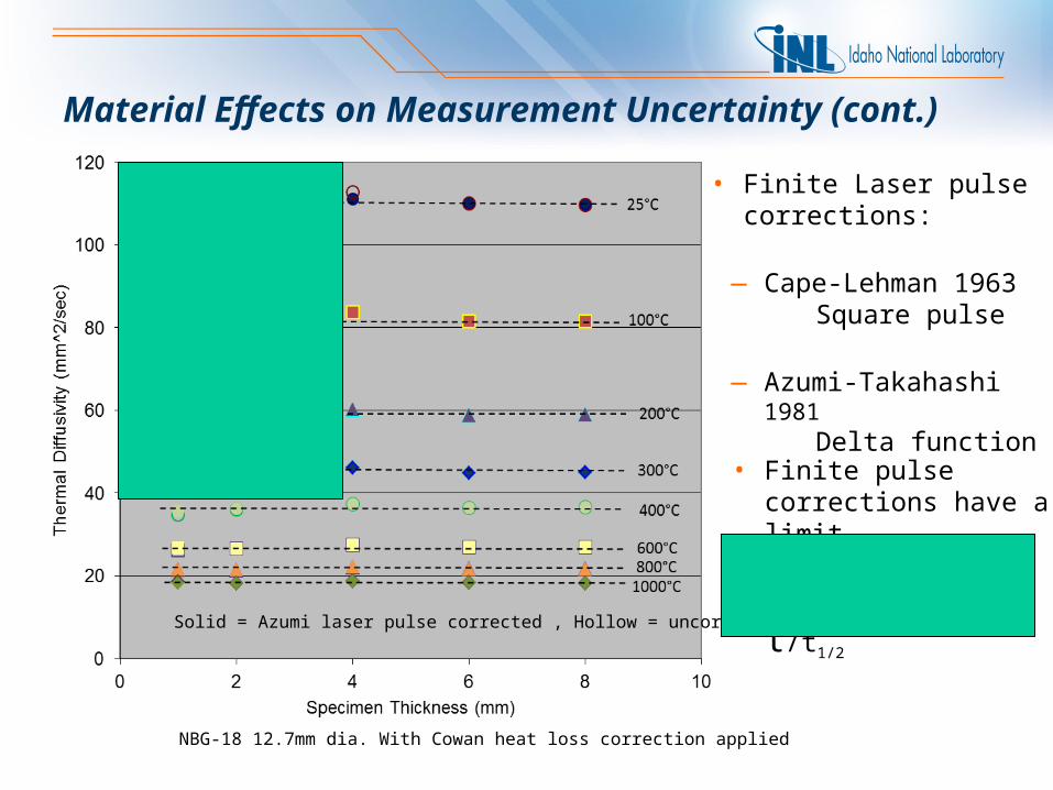
Material Effects on Measurement Uncertainty (cont.)
Solid = Azumi laser pulse corrected , Hollow = uncorrected
• Finite Laser pulse corrections:
— Cape-Lehman 1963Square pulse
— Azumi-Takahashi 1981Delta function
NBG-18 12.7mm dia. With Cowan heat loss correction applied
• Finite pulse corrections have a limit
• Establish a more
generic limit for τ/t1/2
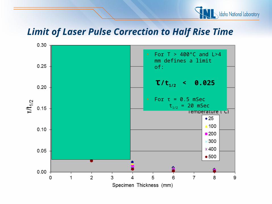
Limit of Laser Pulse Correction to Half Rise Time
• For T > 400°C and L>4 mm defines a limit of:
τ/t1/2 < 0.025
• For τ = 0.5 mSec t1/2 = 20 mSec
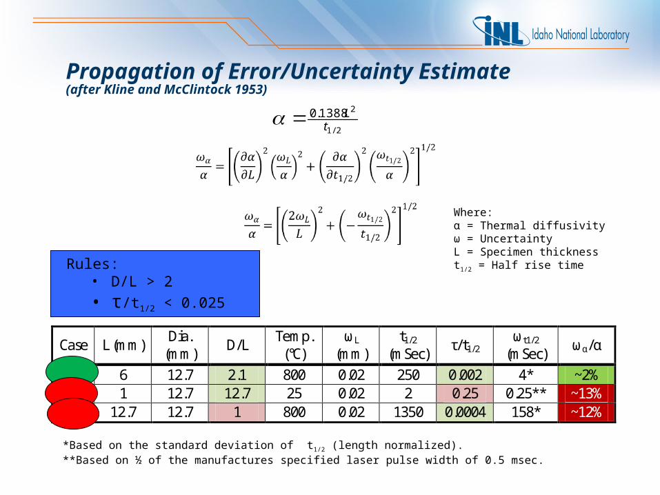
Propagation of Error/Uncertainty Estimate(after Kline and McClintock 1953)
2/1
21388.0t
L
Where:α = Thermal diffusivityω = UncertaintyL = Specimen thicknesst1/2 = Half rise time
*Based on the standard deviation of t1/2 (length normalized).**Based on ½ of the manufactures specified laser pulse width of 0.5 msec.
Rules:• D/L > 2
• τ/t1/2 < 0.025
Case L (mm) Dia. (mm) D/L Temp.
(°C) ωL
(mm) t1/2
(mSec) τ/t1/2 ωt1/2
(mSec) ωα/α
A 6 12.7 2.1 800 0.02 250 0.002 4* ~2% B 1 12.7 12.7 25 0.02 2 0.25 0.25** ~13% C 12.7 12.7 1 800 0.02 1350 0.0004 158* ~12%
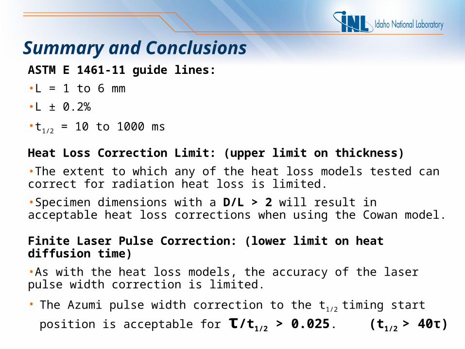
Summary and ConclusionsASTM E 1461-11 guide lines:
•L = 1 to 6 mm
•L ± 0.2%
•t1/2 = 10 to 1000 ms
Heat Loss Correction Limit: (upper limit on thickness)
•The extent to which any of the heat loss models tested can correct for radiation heat loss is limited.
•Specimen dimensions with a D/L > 2 will result in acceptable heat loss corrections when using the Cowan model.
Finite Laser Pulse Correction: (lower limit on heat diffusion time)
•As with the heat loss models, the accuracy of the laser pulse width correction is limited.
• The Azumi pulse width correction to the t1/2 timing start position is acceptable for
τ/t1/2 > 0.025. (t1/2 > 40τ)
Summary and Conclusions (cont.)
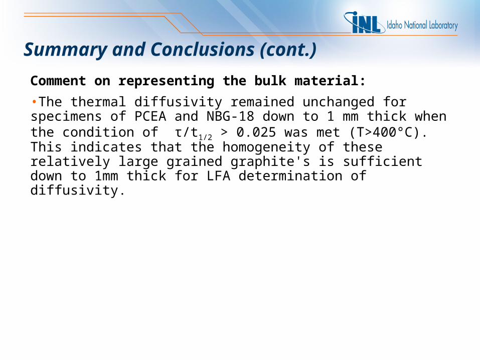
Comment on representing the bulk material:
•The thermal diffusivity remained unchanged for specimens of PCEA and NBG-18 down to 1 mm thick when the condition of τ/t1/2 > 0.025 was met (T>400°C). This indicates that the homogeneity of these relatively large grained graphite's is sufficient down to 1mm thick for LFA determination of diffusivity.