Embed Size (px)
DESCRIPTION
methods of speed control for dc motors
Citation preview

Speed Control Methods of DC Motors
Krishan AroraAssistant Professor
Lovely Professional University

Speed Control of D.C. Motors

Flux control method
It is based on the fact that by varying the flux φ, the motor speed (N α 1/φ) can be changed and hence the name flux control method. In this method, a variable resistance (known as shunt field rheostat) is placed in series with shunt field winding as shown in Fig.


• The shunt field rheostat reduces the shunt field current Ish and hence the flux φ. Therefore, we can only raise the speed of the motor above the normal speed (See Fig. 2). Generally, this method permits to increase the speed in the ratio 3:1. Wider speed ranges tend to produce instability and poor commutation.


Armature control method
• This method is based on the fact that by varying the voltage available across the armature, the back e.m.f and hence the speed of the motor can be changed. Thisis done by inserting a variable resistance RC (known as controller resistance) in series with the armature as shown in Fig. (3).


Voltage control method
• In this method, the voltage source supplying the field current is different from that which supplies the armature. This method avoids the disadvantages of poor speed regulation and low efficiency as in armature control method. However, it is quite expensive. Therefore, this method of speed control is employed for large size motors where efficiency is of great importance.

(i) Multiple voltage control
In this method, the shunt field of the motor is connected permanently across a-fixed voltage source. The armature can be connected across several different voltages through a suitable switchgear. In this way, voltage applied across the armature can be changed. The speed will be approximately proportional to the voltage applied across the armature. Intermediate speeds can be obtained by means of a shunt field regulator.

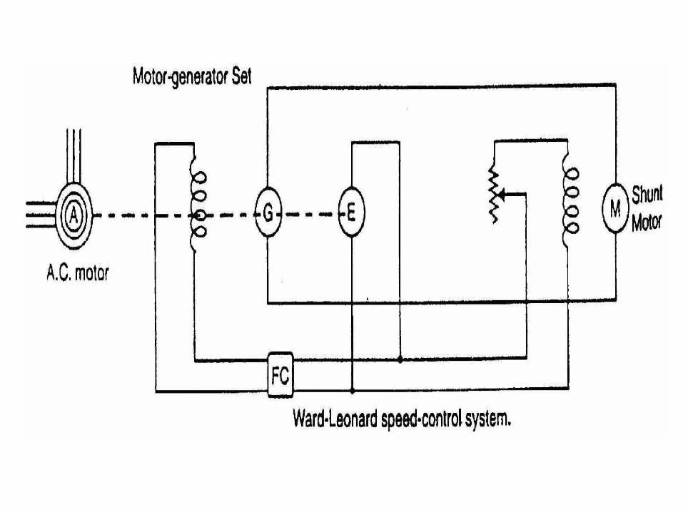
(ii) Ward-Leonard system
In this method, the adjustable voltage for the armature is obtained from an adjustable-voltage generator while the field circuit is supplied from a separate source. This is illustrated in Fig. (5). The armature of the shunt motor M (whose speed is to be controlled) is connected directly to a d.c. generator G driven by a constant-speed a.c. motor A. The field of the shunt motor is supplied from a constant-voltage exciter E. The field of the generator G is also supplied from the exciter E. The voltage of the generator G can be varied by means of its field regulator. By reversing the field current of generator G by controller FC, the voltage applied to the motor may be reversed. Sometimes, a field regulator is included in the field circuit of shunt motor M for additional speed adjustment. With this method, the motor may be operated at any speed upto its maximum speed.

Advantages(a) The speed of the motor can be adjusted through a
wide range without resistance losses which results in high efficiency.
(b) The motor can be brought to a standstill quickly, simply by rapidly reducing the voltage of generator G. When the generator voltage is reduced below the back e.m.f. of the motor, this back e.m.f. sends current through the generator armature, establishing dynamic braking. While this takes place, the generator G operates as a motor driving motor A which returns power to the line.
(c) This method is used for the speed control of large motors when a d.c. supply is not available.

The disadvantage of the method is that a special motor-generator set is required for each motor and the losses in this set are high if the motor is operating under light loads for long periods.


![Fractional Order SMC for Speed Control ofPMSM · ... robust nonlinear control methods have been ... control [II, 12], automatic disturbance rejection ... using predictive functional](https://img.pdfslide.net/doc/110x75/5b8feff309d3f2103e8d1b43/fractional-order-smc-for-speed-control-ofpmsm-robust-nonlinear-control-methods.jpg)