Embed Size (px)
Citation preview
Speed Control of Pneumatic Cylinderby a Microcontroller
Gyorgy Gyorok, Margit MakoAlba Regia University Center
Obuda UniversityBudai Str. 45, H-8000 Szekesfehervar
{gyorok.gyorgy, mako.margit}@arek.uni-obuda.hu
Abstract—In engineering practice we often use pneumaticcylinders, motors, actuators. Popularity of these instruments isunderstandable, since fast and clean, isn’t an electromagneticcompatibility trouble, and can be used in potentially explosiveenvironments. A disadvantage of undetermined speed of move-ment can be mentioned, which is coming from the dynamiccharacteristics of the air is generally difficult to handles.
In the present paper we present such a solution, which can beachieved by using an embedded micro-controller with a specialpulse width modulation control (PWM) which the pneumaticactuators velocity is controllable.
I. INTRODUCTION
A conventional pneumatic actuator arrangement is shownin Fig. 1. If the electrically controlled (µ) valve (v) opens,the pressure air (Pin) enters the chamber of piston (c) andthe plunger moves. Since the air (gas) is compressible so themovement of mechanic (st) is enough hectic.
P in
v
µ c
s(t)
Fig. 1. Conventional pneumatic actuator arrangement.
As the applied gas behavior depends on several physicalparameters (σg) such as the displacement under given unit timeis difficult to determine. The moving of cylinder formally (1)depends on the turned on time of electronic valve (tcyl) andthe mechanical load (ml).
s(t) = f(σg, tcyl ,ml). (1)
The motion, the velocity determining the real issue is thatthe value of (σg) also time dependent in such application.
So, if we put on that the gas internal state is constant and thepistons is fixed, we can write the change in pressure in workchamber of cylinder with buffer container (Pc) in equation (2);
Pc = Pin(1− e−t
Vckg ), (2)
P in
v
∆ p
b
µ
α
π
c
s(t)
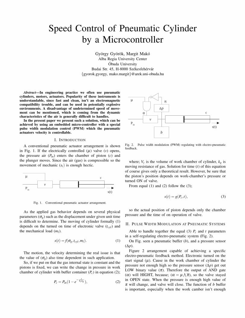
Fig. 2. Pulse width modulation (PWM) regulating with electro-pneumaticfeedback.
where; Vc is the volume of work chamber of cylinder, kg ismoving resistance of gas. Solution for time (t) of this equationof course gives only a theoretical result. However, be sure thatthe piston’s position depends on work-chamber’s pressure orturned ON of valve.
From equal (1) and (2) follow the (3);
s(t) = g(Pc, t), (3)
so the actual position of piston depends only the chamberpressure and the time of on operation of valve.
II. PULSE WIDTH MODULATION AT PNEUMATIC SYSTEMS
Able to handle together the equal (3) Pc and t parametersin a self-regulating electro-pneumatic system (Fig. 2).
On Fig. seen a pneumatic buffer (b), and a pressure sensor(∆p).
Figure 2 arrangement capable of achieving a specificelectro-pneumatic feedback method. Electronic turned on thestart signal (µ). Cause in the work chamber of cylinder thepressure not enough high so the pressure sensor (∆p) get outLOW binary value (π). Therefore the output of AND gate(α) will HIGHT, because; (α = µ
∧π), so the valve stayed
in OPEN state. When the pressure is enough high value ofπ will change, and valve will close. The function of b bufferis important, especially when the work camber isn’t enough
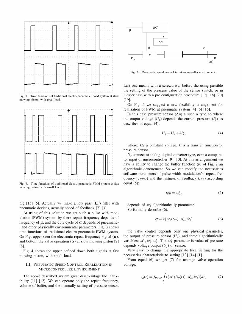
Fig. 3. Time functions of traditional electro-pneumatic PWM system at slowmowing piston, with great load.
Fig. 4. Time functions of traditional electro-pneumatic PWM system at fastmowing piston, with small load.
big [15] [5]. Actually we make a low pass (LP) filter withpneumatic devices, actually speed of feedback [7] [3].
At using of this solution we get such a pulse with mod-ulation (PWM) system by there repeat frequency depends offrequency of µ , and the duty cycle of α depends of pneumatic-, and other physically environmental parameters. Fig. 3 showstime functions of traditional electro-pneumatic PWM system.On Fig. upper seen the electronic repeat frequency signal (µ),and bottom the valve operation (α) at slow mowing piston [2][8].
Fig. 4 shows the upper defined down both signals at fastmowing piston, with small load.
III. PNEUMATIC SPEED CONTROL REALIZATION INMICROCONTROLLER ENVIRONMENT
The above described system great disadvantage the inflex-ibility [11] [12]. We can operate only the repeat frequency,volume of buffer, and the manually setting of pressure sensor.
P in
v
∆ p
µ C µ
α
γ
c
s(t)
Fig. 5. Pneumatic speed control in microcontroller environment.
Last one means with a screwdriver before the using passiblethe setting of the pressure value of the sensor switch, or inluckier case with a pre configuration procedure [17] [18] [20][19].
On Fig. 5 we suggest a new flexibility arrangement forrealization of PWM at pneumatic system [4] [6] [16].
In this case pressure sensor (∆p) a such a type so wherethe output voltage (Uγ ) depends the current pressure (Pc) asdescribes in equal (4);
Uγ =U0 + kPc, (4)
where; U0 a constant voltage, k is a transfer function ofpressure sensor.
Uγ connect to analog-digital converter type, even a compara-tor input of microcontroller [9] [10]. At this arrangenment wehave a ability to change the buffer function (b) of Fig. 2 analgorithmic denouement. So we can modify the necessariessoftware parameters of pulse width modulation’s; repeat fre-quency ( fPWM) and the fastness of feedback (tFB) accordingequal (5);
tFB = A2, (5)
depends of A1 algorithmically parameter.So formally describe (6);
α = g(A1(Uγ),A2,A3) (6)
the valve control depends only one physical parameter,the output of pressure sensor (Uγ ), and three algorithmicallyvariables; A1,A2,A3. The A1 parameter is value of pressuredepends voltage output (Uγ ) of sensor.
Very easy to change the appropriate level setting for thenecessaries characteristic to setting [13] [14] [1] .
From equal (6) we get (7) for average valve operationvoltage;
va(t) = fPWM
t∫0
((A1(Uγ(t)),A2,A3))dt, (7)
where upper integral limit t is (8);
t =1
fPWM. (8)
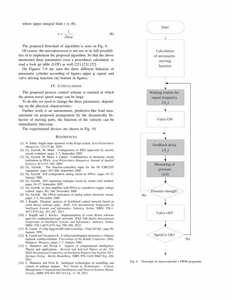
The proposed flowchart of algorithm is seen on Fig. 6.Of course, the microprocessor is not use to its full possibili-
ties of to implement the proposed algorithm. So that the abovementioned three parameters even a procedures calculated, orread a look up table (LOT) as well [21] [23] [22] .
On Figures 7-9 are seen the three different behavior ofpneumatic cylinder according of figures upper µ signal, andvalve driving function (α) bottom in figures.
IV. CONCLUSIONS
The proposed process control scheme is reached at whichthe piston travel speed range can be large.
To do this we need to change the three parameters, depend-ing on the physical characteristics.
Further work is an autonomous, predictive-like load mea-surement on proposed arrangement by the dynamically be-havior of moving parts, the function of the velocity can beimmediately intervene.
The experimental devices are shown in Fig. 10.
REFERENCES
[1] N. Adam. Single input operators of the df kpi system. Acta PolytechnicaHungarica, 7(1):73–86, 2010.
[2] Gy. Gyorok, M. Mako. Configuration of EEG input-unit by electriccircuit evolution. pages 1–7, September 2005.
[3] Gy. Gyorok, M. Mako, J. Lakner. Combinatorics at electronic circuitrealization in FPAA. Acta Polytechnica Hungarica, Journal of AppliedSciences, 6(1):151–160, 2009.
[4] Gy. Gyorok. The function-controlled input for the IN CIRCUITequipment. pages 443–446, September 2006.
[5] Gy. Gyorok. Self configuration analog circuit by FPAA. pages 34–37,January 2006.
[6] Gy. Gyorok. Self organizing analogue circuit by monte carlo method.pages 34–37, September 2007.
[7] Gy. Gyorok. A-class amplifier with FPAA as a predictive supply voltagecontrol. pages 361–368, November 2008.
[8] Gy. Gyorok. The FPAA realization of analog robust electronic circuit.pages 1–5, November 2009.
[9] J. Kopjak. Dynamic analysis of distributed control network based onevent driven software gates. IEEE 11th International Symposium onIntelligent Systems and Informatics, Subotica, Serbia, ISBN: 978-1-4673-4751-8:p. 293–297, 2013.
[10] J. Kopjak and J. Kovacs. Implementation of event driven softwaregates for combinational logic networks. IEEE 10th Jubilee InternationalSymposium on Intelligent Systems and Informatics, Subotica, Serbia,ISBN: 978-1-4673-4751-8:p. 299–304, 2012.
[11] K. Lamar. A vilag leggyorsabb mikrovezerloje. ChipCAD Kft., page 96,January 1999.
[12] K. Lamar and Veszpremi K. A mikroszamıtogepek ternyerese a villamoshajtasok szabalyozasaban. Proceedings of the Kando Conference 2002,Budapest, Hungary, pages 1–7, January 2002.
[13] L. Madarasz and Zivcak J. Aspects of computational intelligence:Theory and applications. Revised and Selected Papers of the 15thIEEE International Conference on Intelligent Engineering Systems 2011,Springer-Verlag , Berlin Heidelberg, ISBN 978-3-642-30667-9:p. 436,2011.
[14] L. Madarasz and Fozo R. Intelligent technologies in modelling andcontrol of turbojet engines. New Trends in Technologies : Control,Management, Computational Intellingence and Network Systems, Rijeka,Croatia, ISBN 978-953-307-213-5:p. 17–38, 2011.
No
Valve ON
Valve OFF
Start
Calculation of necessaries
moving function
Waiting routine for repeat frequency
( A 1 )
Pressure enough?
Speed is OK? No
Feedback delay ( A 2 )
Measuring of pressure
(A3)
Fig. 6. Flowchart of microcontroller’s PWM programm.
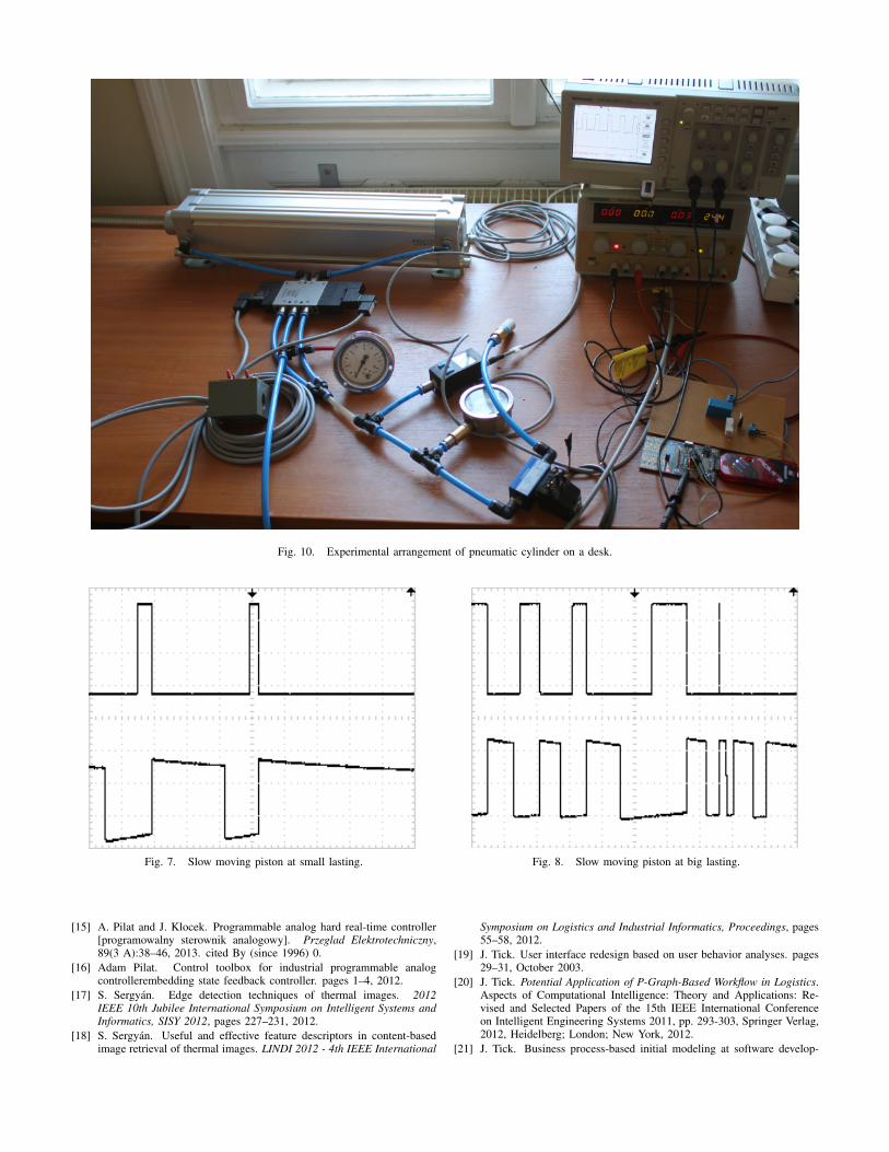
Fig. 10. Experimental arrangement of pneumatic cylinder on a desk.
Fig. 7. Slow moving piston at small lasting.
[15] A. Pilat and J. Klocek. Programmable analog hard real-time controller[programowalny sterownik analogowy]. Przeglad Elektrotechniczny,89(3 A):38–46, 2013. cited By (since 1996) 0.
[16] Adam Pilat. Control toolbox for industrial programmable analogcontrollerembedding state feedback controller. pages 1–4, 2012.
[17] S. Sergyan. Edge detection techniques of thermal images. 2012IEEE 10th Jubilee International Symposium on Intelligent Systems andInformatics, SISY 2012, pages 227–231, 2012.
[18] S. Sergyan. Useful and effective feature descriptors in content-basedimage retrieval of thermal images. LINDI 2012 - 4th IEEE International
Fig. 8. Slow moving piston at big lasting.
Symposium on Logistics and Industrial Informatics, Proceedings, pages55–58, 2012.
[19] J. Tick. User interface redesign based on user behavior analyses. pages29–31, October 2003.
[20] J. Tick. Potential Application of P-Graph-Based Workflow in Logistics.Aspects of Computational Intelligence: Theory and Applications: Re-vised and Selected Papers of the 15th IEEE International Conferenceon Intelligent Engineering Systems 2011, pp. 293-303, Springer Verlag,2012, Heidelberg; London; New York, 2012.
[21] J. Tick. Business process-based initial modeling at software develop-
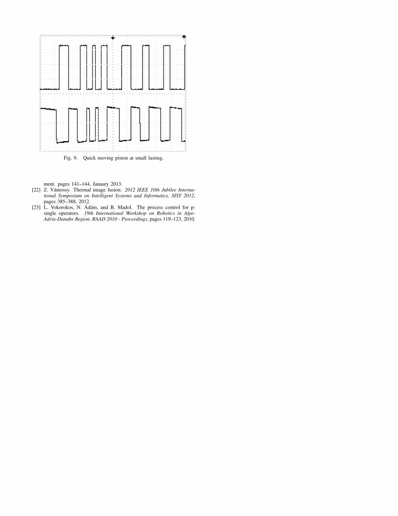
Fig. 9. Quick moving piston at small lasting.
ment. pages 141–144, January 2013.[22] Z. Vamossy. Thermal image fusion. 2012 IEEE 10th Jubilee Interna-
tional Symposium on Intelligent Systems and Informatics, SISY 2012,pages 385–388, 2012.
[23] L. Vokorokos, N. Adam, and B. Madol. The process control for p-single operators. 19th International Workshop on Robotics in Alpe-Adria-Danube Region, RAAD 2010 - Proceedings, pages 119–123, 2010.