Embed Size (px)
Citation preview

2
How to Order
2 2 1 01 06 SAS 1F
Body size M3, M5 standard1/8, 1/4 standard
3/8 standard1/2 standard
1234
Style Elbow
Universal23
Control
With One-touch fittings
Meter outMeter in
01
Thread
R(PT)Unified thread (10-32UNF)
Meter thread (M3, M5)_
N
M3M5
10-32UNF1/81/43/81/2
M5U10/32
01020304
M3Port size
ø3.2∗
ø4ø6ø8
ø10ø12
Millimeter
∗ø1/8" tube should be used.
0406081012
23
Applicable tube O.D.
ø1/8"ø5/32"ø3/16"ø1/4"
ø5/16"ø3/8"ø1/2"
Inch
030507091113
01
NoneWith sealant
Hexagon lock nutElectroless nickel plating
SKN
_Option
∗If more than one option is required, write option parts numbers in the order of "S", "K", "N".
Needle Valve/Flow Characteristics
NPT
AS1201F-M3, AS1211F-M3AS1301F-M3, AS1311F-M3
Flo
w (l/m
in(A
NR
))
Flo
w (l/m
in(A
NR
))
Flo
w (l/m
in(A
NR
))
Flo
w (l/m
in(A
NR
))
Flo
w (l/m
in(A
NR
))
Flo
w (l/m
in(A
NR
))
20
15
10
5
0 5
10
0.1
0.2
0.3
Needle rotation (Turns)
Needle rotation (Turns) Needle rotation (Turns) Needle rotation (Turns)
Needle rotation (Turns)
Note) "-U10/32" is the same as "M5".
Needle rotation (Turns)
Effe
ctiv
e ar
ea (
mm
2 )
Effe
ctiv
e ar
ea (
mm
2 )
Effe
ctiv
e ar
ea (
mm
2 )
Effe
ctiv
e ar
ea (
mm
2 )
Effe
ctiv
e ar
ea (
mm
2 )
Effe
ctiv
e ar
ea (
mm
2 )
Supply pressure: 0.5MPa Supply pressure: 0.5MPa
Supply pressure: 0.5MPa Supply pressure: 0.5MPa Supply pressure: 0.5MPa
AS1201F-M5, AS1211F-M5AS1301F-M5, AS1311F-M5
100
50
05 10
1.5
1.0
0.5
0
200
100
0
3
2
1
05 10
06,0
8,10
04
AS2301F-01, AS2311F-01AS2201F-01, AS2211F-01
AS2301F-02, AS2311F-02AS2201F-02, AS2211F-02 AS3201F, AS3211F
AS4301F, AS4311FAS4201F, AS4211F
AS3301F, AS3311F
400
300
200
100
0 5 10 0
6
4
2
06
04
1000
500
0
10, 12
08
06
16
14
12
10
8
64
2
0
1500
1000
500
0
25
20
15
1010 550
5
10
Supply pressure: 0.5MPa
121080
, 10
Minimizes installationtime and cost
Tube swivels 360°
Nylon, Soft nylon and Polyurethane tubing.
The increased number of needle rotations(8 to 10 turns) permits easier control at lower speed.
Universal style permits 360° piping swivel.
Application to inch size tubing
Operating pressure1MPa max.
Accepts
Retainer prevents accidentalloss of needle
Optional:Hexagonal lock nut,Nickel plated optionNumber of needle rotations hasbeen increased (8 to 10 turns)
•Metric size (Release bushing: White color) ø3.2, ø4, ø6, ø8, ø10, ø12
•Inch size (Release bushing: Orange color) ø1/8", ø5/32", ø3/16", ø1/4", ø5/16", ø3/8", ø1/2"
Model
Specifications
Air Flow/Effective Area
Elbow
Proof pressure
Max. operating pressure
Min. operating pressure
Ambient and fluid temperature
Number of needle rotations
Applicable tubes(2)
Option
Model
Metric size ø3.2, ø4
ø1/8",ø5/32"
20
0.3
100
1.5
180
2.7
230
3.5
260
4
390
6
460
7
660
10
790
12
920
14
1580
24
1710
26
ø3.2, ø4
ø1/8",ø5/32"
ø3.2, ø4, ø6
ø1/8",ø5/32"
ø6, ø8, ø10 ø8, ø10
ø3/16", ø1/4",ø5/16"
ø1/4", ø5/16",ø3/8"
ø4
ø5/32"
ø6 ø6 ø8 ø10 ø12
ø3/16" ø5/16" ø3/8" ø1/2"
ø10, ø12
ø3/8"ø1/4"Inch size
Eff. area (mm2)
Air (l/min(ANR))
TubeO.D.
Controlled(Free) flow
1.5MPa
1MPa
0.1MPa
–5 to 60°C (No freezing)
10 turns (8 turns(1))
Nylon, Soft nylon, Polyurethane
Sealant(3), Hexagon lock nut, Electroless nickel plated(4)
Note 1) ∗Only elbow style.Note 2) Distinction between meter-out/meter-in types by appearance. They are distinguished by the lock nut. The lock nut on the meter-out type is electroless nickel plated, while the meter-in type is black zinc chromate plated.Note 3) : Nickel plated model is standard.
Note 1) AS12�1F-M5, AS12�1F-U10/32 AS13�1F-M5, AS13�1F-U10/32Note 2) Pay attention to the maximum operating pressure when soft nylon or Polyurethane is used. (Refer to p.7-146 and 7-147 in "Best Pneumatics" for further information.)Note 3) Nickel plated AS12�1F and AS13�1F are standard, not equipped with a seal.Note 4) Brass parts are all electroless nickel plated.
Notes) Supply pressure: 0.5MPa, Temperature: 20°C.U10/32 has the same specification as M5.
AS12�1F-M3
AS12�1F-M5
AS12�1F-U10/32
AS22�1F-01
AS22�1F-02
AS32�1F-02
AS32�1F-03
AS42�1F-04
Universal Port size
Applicable tube O.D. Applicablecylinder bore
size (mm)Metric size Inch size
M3
M5
10-32UNF
R(PT)1/8
R(PT)1/4
R(PT)1/4
R(PT)3/8
R(PT)1/2
2.5, 4, 6
6, 10, 16, 20
6, 10, 16, 20
20, 25, 32
20, 25, 32, 40
40, 50, 63
40, 50, 63
63, 80, 100
AS13�1F-M3
AS13�1F-M5
AS13�1F-U10/32
AS23�1F-01
AS23�1F-02
AS33�1F-02
AS33�1F-03
AS43�1F-04
3.2 4 6 8 10 12 1/8" 5/32" 3/16" 1/4" 5/16" 3/8" 1/2"
AS22�1F-01AS23�1F-01
AS22�1F-02AS23�1F-02
AS32�1FAS33�1F
AS42�1FAS43�1F
AS12�1F-M3AS13�1F-M3
AS12�1F-M5AS13�1F-M5
Elbow styleUniversal style JIS Symbol
Reduces the mounting height and enables compact machinery design. Effective area is larger than the former model.
Speed Controller with One-touch Fittings
Series ASElbow Style, Universal Style
∗

3
How to Order
2 2 1 01 06 SAS 1F
Body size M3, M5 standard1/8, 1/4 standard
3/8 standard1/2 standard
1234
Style Elbow
Universal23
Control
With One-touch fittings
Meter outMeter in
01
Thread
R(PT)Unified thread (10-32UNF)
Meter thread (M3, M5)_
N
M3M5
10-32UNF1/81/43/81/2
M5U10/32
01020304
M3Port size
ø3.2∗
ø4ø6ø8
ø10ø12
Millimeter
∗ø1/8" tube should be used.
0406081012
23
Applicable tube O.D.
ø1/8"ø5/32"ø3/16"ø1/4"
ø5/16"ø3/8"ø1/2"
Inch
030507091113
01
NoneWith sealant
Hexagon lock nutElectroless nickel plating
SKN
_Option
∗If more than one option is required, write option parts numbers in the order of "S", "K", "N".
Needle Valve/Flow Characteristics
NPT
AS1201F-M3, AS1211F-M3AS1301F-M3, AS1311F-M3
Flo
w (l/m
in(A
NR
))
Flo
w (l/m
in(A
NR
))
Flo
w (l/m
in(A
NR
))
Flo
w (l/m
in(A
NR
))
Flo
w (l/m
in(A
NR
))
Flo
w (l/m
in(A
NR
))
20
15
10
5
0 5
10
0.1
0.2
0.3
Needle rotation (Turns)
Needle rotation (Turns) Needle rotation (Turns) Needle rotation (Turns)
Needle rotation (Turns)
Note) "-U10/32" is the same as "M5".
Needle rotation (Turns)
Effe
ctiv
e ar
ea (
mm
2 )
Effe
ctiv
e ar
ea (
mm
2 )
Effe
ctiv
e ar
ea (
mm
2 )
Effe
ctiv
e ar
ea (
mm
2 )
Effe
ctiv
e ar
ea (
mm
2 )
Effe
ctiv
e ar
ea (
mm
2 )
Supply pressure: 0.5MPa Supply pressure: 0.5MPa
Supply pressure: 0.5MPa Supply pressure: 0.5MPa Supply pressure: 0.5MPa
AS1201F-M5, AS1211F-M5AS1301F-M5, AS1311F-M5
100
50
05 10
1.5
1.0
0.5
0
200
100
0
3
2
1
05 10
06,0
8,10
04
AS2301F-01, AS2311F-01AS2201F-01, AS2211F-01
AS2301F-02, AS2311F-02AS2201F-02, AS2211F-02 AS3201F, AS3211F
AS4301F, AS4311FAS4201F, AS4211F
AS3301F, AS3311F
400
300
200
100
0 5 10 0
6
4
2
06
04
1000
500
0
10, 12
08
06
16
14
12
10
8
64
2
0
1500
1000
500
0
25
20
15
1010 550
5
10
Supply pressure: 0.5MPa12
1080, 1
0
With One-touch Fittings: Elbow/Universal Style Series AS

4
Elbow styleMeter-out
M3 portM5 port
U10/32 port
Universal styleMeter-out
Meter-in Meter-in
Construction
M3 portM5 port
U10/32 port
M3 portM5 port
U10/32 port
M3 portM5 port
U10/32 port
Series AS

5
No. Description Material Note No. Description Material NoteBody AHandleBody BNeedleNeedle guideSeat ringLock nutU-packingCassettePackingO ringO ringO ringO ringGasket
q
w
e
r
t
y
u
i
o
!0
!1
!2
!3
!4
!5
PBTPBT
Brass(1)
BrassBrassBrass
Brass(3)
NBRPOM, Stainless steel
NBRNBRNBRNBRNBR
NBR, Stainless steel
Electroless nickel platedElectroless nickel platedElectroless nickel platedSee Note 2
Electroless nickel plated(4)
Component Parts Component Parts
Body AElbow bodyHandleBody BNeedleNeedle guideSeat ringLock nutU-packingCassettePackingO ringO ringO ringO ringO ringSpacerGasket
q
w
e
r
t
y
u
i
o
!0
!1
!2
!3
!4
!5
!6
!7
!8
PBTPBTPBT
Brass(1)
BrassBrassBrass
Brass(3)
NBRPOM, Stainless steel
NBRNBRNBRNBRNBRNBR
POM(5)
NBR, Stainless steel
Construction
Note 1) AS121F-M3: StainlessNote 2) AS321F-02: Electroless nickel platedNote 3) AS21F: SteelNote 4) Meter-in type: Black zinc chromated
Elbow styleMeter-out AS3201F-02
Universal styleMeter-out AS3301F-02
Meter-in AS3211F-02 Meter-in AS3311F-02
Electroless nickel platedElectroless nickel platedElectroless nickel platedSee Note 2Electroless nickel plated(4)
Note 1) AS131F-M3: StainlessNote 2) AS331F-02: Electroless nickel platedNote 3) AS21F: SteelNote 4) Meter-in type: Black zinc chromatedNote 5) ø3/16", ø1/4", ø3/8", ø1/2": Brass
With One-touch Fittings: Elbow/Universal Style Series AS

6
Elbow Style
Metric
Model
AS12�1F-M3-23
AS12�1F-M3-04
AS12�1F-M5-23
AS12�1F-U10/32-23
AS12�1F-M5-04
AS12�1F-U10/32-04
AS12�1F-M5-06
AS12�1F-U10/32-06
AS22�1F-01-23
AS22�1F-01-04
AS22�1F-01-06
AS22�1F-01-08
AS22�1F-01-10
AS22�1F-02-04
AS22�1F-02-06
AS22�1F-02-08
AS22�1F-02-10
AS32�1F-02-06
AS32�1F-02-08
AS32�1F-02-10
AS32�1F-02-12
AS32�1F-03-06
AS32�1F-03-08
AS32�1F-03-10
AS32�1F-03-12
AS42�1F-04-10
AS42�1F-04-12
TubeO.D.
d
3.25.5
8
12(12.7)
17 (17.5)
12 (12.7)
19
24(23.8)
24(23.8)
14.2
18.5
23
23
28.6
7.2 16.1 19.7 26.6 24.1 24 21.5 44
8.4
9.3
10.5
1012.7
3.2
4 9.6
17
12.3
11.76
3.2
4
6
8
10
4
6
8
10
6
8
10
12
6
8
10
12
10
12
8.4
9.3
11.6
9.3
9.3
11.6
15.2
18.5
10.4
12.8
15.2
18.5
12.8 27.8
15.2
18.5
20.9
12.8
15.2
18.5
20.9
18.5
20.9
20.4 16
20.4
20.4
25.3
33.1
19
21
18.5
21
25.2
25.2
27.2
33.9
16
1732
18.5
21
34
36
29.5
31.8
32.8
27.8
29.5
31.8
32.8
33.6
34.6
17 60
18.5
21
22
17
18.5
21
22
21
22
63
67
69
55
57
59
61
100
101
17.3
17.3
18.1
22.1
22.1 28.6 25.8
40.2
42.8
34.4
49.6
32.1
25
35.2
37.8
29.4
42.1
27.1 13.5
22.2 7
22.9
39.3
27.5
27.5
27.5
32.4
40.2
34.4
34.4
36.4
43.2
41
43.3
44.3
39.3
41
43.3
44.3
47.9
48.9
12.7
13.5
12.7
T D1H(1) D2 L1 L2 L3 M1L4
MIN. MAX. MIN.MAX.
A(2) Weight(g) Model
Tube O.D.
dT D1 D2 L1 L2 L3 M1
L4
MIN. MAX. MIN.MAX.
A (2)Weight
(g)
M3
M5
10-32UNF
M5
10-32UNF
M5
10-32UNF
R(PT)1/8
R(PT)1/4
R(PT)1/2
Note 1) ( ) are the dimensions of NPT thread.Note 2) Reference thread dimensions after being screwed in.
Note 1) ( ) are the dimensions of NPT thread.Note 2) Reference thread dimensions after being screwed in.
M3 portM5 portU10/32 port
R(PT)3/8
Inch
AS12�1F-M3-01
AS12�1F-M3-03
AS12�1F-M5-01
AS12�1F-U10/32-01
AS12�1F-M5-03
AS12�1F-U10/32-03
AS22�1F-01-01
AS22�1F-01-03
AS22�1F-01-05
AS22�1F-01-07
AS22�1F-01-09
AS22�1F-02-03
AS22�1F-02-05
AS22�1F-02-07
AS22�1F-02-09
AS22�1F-02-11
AS32�1F-02-07
AS32�1F-02-09
AS32�1F-02-11
AS32�1F-03-07
AS32�1F-03-09
AS32�1F-03-11
AS42�1F-04-11
AS42�1F-04-13
1/8"
5/32"
1/8"
1/8"
5/32"
5/32"
1/8"
5/32"
3/16"
1/4"
5/16"
5/32"
3/16"
1/4"
5/16"
3/8"
1/4"
5/16"
3/8"
1/4"
5/16"
3/8"
3/8"
1/2"
5.5
8
19
14.2
28.6
23
23
7.2 19.7 26.6 24.1 24 21.5 48.4
9.3
10.5
1012.7
9.6 12.3 28.6 25.8 25 22.2
8.4
9.3
9.3
9.3
11.4
10.4
11.4
13.2 18.5
15.2
17.9
13.2
15.2 41
17.9
13.2
15.2
17.9
17.9
21.7
27.5
17
16
19
21
27.5
30.2 32.1 27.1
13.2 31
15.2 32.4
34.4
34.2
16
17
34.5 34.4 29.4
36.4
43.2
39.3
18.5
21
21
17
36
36
34
32
60
43.3
39.3
41
43.3
47.9
49.5
18.5 63
21
17
18.5
21
21
22
67
55
57
59
100
101
22.1
22.1
49.6
42.8
42.1
40.2 35.2
37.8
21
18.5
16.5
712.7
12.7
M3
M5
10-32UNF
M5
10-32UNF
1/8
1/4
3/8
1/2
16.1
29.5
20.4
20.4
23.1
25.2
24.9
25.2
27.2
33.9
27.8
31.8
27.8
29.5
31.8
33.6
35.2
23.9
25.3
17.3
17.3
17 (17.5)
Elbow Style
File Port size
Detail No.
Tube O.D.Model
SAS21F1N
AS12�1F-M3-�
AS12�1F-M5-�
AS22�1F-01-�S
AS22�1F-02-�S
AS32�1F-03-�S
AS42�1F-04-�S
M3
M5
R(PT)1/8
R(PT)1/4
R(PT)3/8
R(PT)1/2
3.2 4 6 8 10 12
#1 #2
#3 #4 #5
#6 #7 #8 #9 #10
#11 #12 #13 #14
#15 #16 #17 #18
#19 #20
Applicable tube O.D. ød (Width across flats)
Applicable tube O.D. ød(Widthacrossflats)
_ _ ___
___ _ _ _
_
____
H(1)
13.4
19.8
21.3
24.5
45.4
48.3
39.9
56.7
35.2
14.1
17,7
19,5
40.4
43.3
34.9
49.2
30,2
13.4
19.8
21.3
24.5
45.4
48.3
39.9
56.7
35.2
14.1
17,7
19,5
40.4
43.3
34.9
49.2
30,2
19,5
Series AS
7
With One-touch Fittings: Elbow/Universal Style Series ASUniversal Style
Metric
Model
AS13�1F-M3-23
AS13�1F-M3-04
AS13�1F-M5-23
AS13�1F-U10/32-23
AS13�1F-M5-04
AS13�1F-U10/32-04
AS13�1F-M5-06
AS13�1F-U10/32-06
AS23�1F-01-23
AS23�1F-01-04
AS23�1F-01-06
AS23�1F-01-08
AS23�1F-02-04
AS23�1F-02-06
AS23�1F-02-08
AS23�1F-02-10
AS33�1F-02-06
AS33�1F-02-08
AS33�1F-02-10
AS33�1F-02-12
AS33�1F-03-06
AS33�1F-03-08
AS33�1F-03-10
AS33�1F-03-12
AS43�1F-04-10
AS43�1F-04-12
3.25.5
8
12(12.7)
12(12.7)
17(17.5)
17(17.5)
24(23.8)
24(23.8)
19
14.2
18.5
23
23
28.6
7.228.3
24.1 244
54
8.4
9.3
3.2
4 9.6
18
28.7
6
3.2
4
6
8
4
6
8
10
6
8
10
12
6
8
10
12
10
12
8.4
9.3
11.6
8.4
9.3
11.6
15.2
10.4
12.8
15.2
18.5
12.8
15.2
18.5
20.9
12.8
15.2
18.5
20.9
18.5
21.7
17
21
36
33
32
40
60
63
67
69
56
59
63
65
104
106
7.2
12.9
9.3
10.9
12.9
10.9
12.9
12.9
12.9
16.2
12.9
12.9
16.2
16.2
19.4
9.3
10.1
20.6
13.1
14
16.2
16.2
18.4
18.3
20.2
20.6
23
23
20.6
20.6
23
23
25.8
26.8
10.8
26.6
28.6 25.8
40
42.8
34.4
49.6
32.1
25
21.5
35
37.8
29.4
42.1
27.1
22.2 7
31.8
17.9
18.3
19.8
20.3
21.4
38.5
24.4
24.9
26.9
30.9
30.6
34
35.2
38.7
39.7
43.7
44.9
38.5
39.7
43.7
44.9
49.4
52
17.6
28.617.9
17.5
25.2
31
20.6
17.5
22.9
28.2
21.9
28.2
25.2
28.2
32.6
34.4
25.2
28.2
32.6
34.4
32.6
36.3
12.7
18.5
16
17
18.5
21
17
18.5
21
22
17
18.5
21
22
21
22
13.5
12.7
13.5
12.7
T D1H(1) D2 D3 L1 L2 L3 L4 M1L5
MIN. MAX. MIN.MAX.Weight
(g)
M3
M5
10-32UNF
M5
10-32UNF
M5
10-32UNF
1/8
1/4
1/2
3/8
Note 1) ( ) are the dimensions of NPT threadNote 2) Reference thread dimensions after being screwed in
5
4
18
17
7
M3 portM5 portU10/32 port
MIN. MAX. MIN.MAX.
Inch
AS13�1F-M3-01
AS13�1F-M3-03
AS13�1F-M5-01
AS13�1F-U10/32-01
AS13�1F-M5-03
AS13�1F-U10/32-03
AS23�1F-01-01
AS23�1F-01-03
AS23�1F-01-05
AS23�1F-01-07
AS23�1F-01-09
AS23�1F-02-03
AS23�1F-02-05
AS23�1F-02-07
AS23�1F-02-09
AS23�1F-02-11
AS33�1F-02-07
AS33�1F-02-09
AS33�1F-02-11
AS33�1F-03-07
AS33�1F-03-09
AS33�1F-03-11
AS43�1F-04-11
AS43�1F-04-13
d
1/8"
5/32"
1/8"
1/8"
5/32"
5/32"
1/8"
5/32"
3/16"
1/4"
5/16"
5/32"
3/16"
1/4"
5/16"
3/8"
1/4"
5/16"
3/8"
1/4"
5/16"
3/8"
3/8"
1/2"
5.5
8
19
14.2
28.6
23
23
7.2 7.228.317.6
28.617.926.6 24.1 24 21.5
8.4
9.3
17.9
18.312.7
9.6
28.2
17.59.3 10.8 28.7 28.6 25.8 25 22.2
8.4
9.3
8.4
9.3
11.6
10.4
11.6
13.2 18.5
15.2
18.5
13.2
15.2 39.7
18.5
13.2
15.2
18.5
18.5
21.7
26.8 32.1 27.1
13.2 29.9
15.2 30.9
30.6
31.1
16
16.523.9
28.2
34.2 34.4 29.4
35.2 28.2
38.7
38.7
31
17
18.5
21
17
43.7
38.7
39.7
43.7
49.4
52
18.5
21
17
18.5
21
21
22
12.9
10.9
10.9
10.9
12.9
12.9
16.2
12.9
12.9
16.2
16.2
19.4
12.9
12.9
19.8
20.3
49.6
42.8
42.1
28.2 40.2 35.2
37.8
18.5
17
16.5
12.7
12.717.59.3 13.124.4
24.9
M3
M5
10-32UNF
M5
10-32UNF
1/8
1/4
3/8
1/2
10.1
20.6
14 23.9
16.2 21.9
16.2
18.3 25.6
18.3
20.2
20.6 25.6
23
20.6
32.6
25.6
20.6
23 32.6
25.8
26.8
32.6
36.3
16.2 25.6
16.2
ModelTube O.D. T D1 D2 D3 L1 L2 L3 L4 M1
L5Weight
(g)
19
21
32
33
36
39
40
60
63
69
56
59
65
104
106
H(1)A(2)
Note 1) ( ) are the dimensions of NPT threadNote 2) Reference thread dimensions after being screwed in
File Port sizeDetail No.
Tube O.D.Model
SAS31F1N
AS13 �1F-M3-�
AS13 �1F-M5-�
AS23 �1F-01-�S
AS23 �1F-02-�S
AS33 �1F-03-�S
AS43 �1F-04-�S
M3
M5
R(PT)1/8
R(PT)1/4
R(PT)3/8
R(PT)1/2
3.2 4 6 8 10 12
#1 #2
#3 #4 #5
#6 #7 #8
_
#9_
#10 #11 #12
_ _ __ _
___
__ _
_ _ _
_
#13
#14 #15 #16 #17
#18 #19
Universal Style
A(2)
d
47.9
45.4
48.3
39.9
56.7
35.2
40.4
43.3
34.9
49.2
30.2
30.9
45.1
36.3
40.8
39.6
42.1
46.5
49.5
53.9
55.7
45
48
52.4
54.2
57,1
60.8
54.4
56.7
48.8
35.2 30.2
42.1
39.9
40.8
34.9
47.4
46.5
49.2
43.8
48 45.4 40.4
30.9
30.9
39.6
45.1
50
56.2
45
52.4
54.4
57.1
36.3
Elbow Style
Metric
Model
AS12�1F-M3-23
AS12�1F-M3-04
AS12�1F-M5-23
AS12�1F-U10/32-23
AS12�1F-M5-04
AS12�1F-U10/32-04
AS12�1F-M5-06
AS12�1F-U10/32-06
AS22�1F-01-23
AS22�1F-01-04
AS22�1F-01-06
AS22�1F-01-08
AS22�1F-01-10
AS22�1F-02-04
AS22�1F-02-06
AS22�1F-02-08
AS22�1F-02-10
AS32�1F-02-06
AS32�1F-02-08
AS32�1F-02-10
AS32�1F-02-12
AS32�1F-03-06
AS32�1F-03-08
AS32�1F-03-10
AS32�1F-03-12
AS42�1F-04-10
AS42�1F-04-12
TubeO.D.
d
3.25.5
8
12(12.7)
17 (17.5)
12 (12.7)
19
24(23.8)
24(23.8)
14.2
18.5
23
23
28.6
7.2 16.1 19.7 26.6 24.1 24 21.5 44
8.4
9.3
10.5
1012.7
3.2
4 9.6
17
12.3
11.76
3.2
4
6
8
10
4
6
8
10
6
8
10
12
6
8
10
12
10
12
8.4
9.3
11.6
9.3
9.3
11.6
15.2
18.5
10.4
12.8
15.2
18.5
12.8 27.8
15.2
18.5
20.9
12.8
15.2
18.5
20.9
18.5
20.9
20.4 16
20.4
20.4
25.3
33.1
19
21
18.5
21
25.2
25.2
27.2
33.9
16
1732
18.5
21
34
36
29.5
31.8
32.8
27.8
29.5
31.8
32.8
33.6
34.6
17 60
18.5
21
22
17
18.5
21
22
21
22
63
67
69
55
57
59
61
100
101
17.3
17.3
18.1
22.1
22.1 28.6 25.8
40.2
42.8
34.4
49.6
32.1
25
35.2
37.8
29.4
42.1
27.1 13.5
22.2 7
22.9
39.3
27.5
27.5
27.5
32.4
40.2
34.4
34.4
36.4
43.2
41
43.3
44.3
39.3
41
43.3
44.3
47.9
48.9
12.7
13.5
12.7
T D1H(1) D2 L1 L2 L3 M1L4
MIN. MAX. MIN.MAX.
A(2) Weight(g) Model
Tube O.D.
dT D1 D2 L1 L2 L3 M1
L4
MIN. MAX. MIN.MAX.
A (2)Weight
(g)
M3
M5
10-32UNF
M5
10-32UNF
M5
10-32UNF
R(PT)1/8
R(PT)1/4
R(PT)1/2
Note 1) ( ) are the dimensions of NPT thread.Note 2) Reference thread dimensions after being screwed in.
Note 1) ( ) are the dimensions of NPT thread.Note 2) Reference thread dimensions after being screwed in.
M3 portM5 portU10/32 port
R(PT)3/8
Inch
AS12�1F-M3-01
AS12�1F-M3-03
AS12�1F-M5-01
AS12�1F-U10/32-01
AS12�1F-M5-03
AS12�1F-U10/32-03
AS22�1F-01-01
AS22�1F-01-03
AS22�1F-01-05
AS22�1F-01-07
AS22�1F-01-09
AS22�1F-02-03
AS22�1F-02-05
AS22�1F-02-07
AS22�1F-02-09
AS22�1F-02-11
AS32�1F-02-07
AS32�1F-02-09
AS32�1F-02-11
AS32�1F-03-07
AS32�1F-03-09
AS32�1F-03-11
AS42�1F-04-11
AS42�1F-04-13
1/8"
5/32"
1/8"
1/8"
5/32"
5/32"
1/8"
5/32"
3/16"
1/4"
5/16"
5/32"
3/16"
1/4"
5/16"
3/8"
1/4"
5/16"
3/8"
1/4"
5/16"
3/8"
3/8"
1/2"
5.5
8
19
14.2
28.6
23
23
7.2 19.7 26.6 24.1 24 21.5 48.4
9.3
10.5
1012.7
9.6 12.3 28.6 25.8 25 22.2
8.4
9.3
9.3
9.3
11.4
10.4
11.4
13.2 18.5
15.2
17.9
13.2
15.2 41
17.9
13.2
15.2
17.9
17.9
21.7
27.5
17
16
19
21
27.5
30.2 32.1 27.1
13.2 31
15.2 32.4
34.4
34.2
16
17
34.5 34.4 29.4
36.4
43.2
39.3
18.5
21
21
17
36
36
34
32
60
43.3
39.3
41
43.3
47.9
49.5
18.5 63
21
17
18.5
21
21
22
67
55
57
59
100
101
22.1
22.1
49.6
42.8
42.1
40.2 35.2
37.8
21
18.5
16.5
712.7
12.7
M3
M5
10-32UNF
M5
10-32UNF
1/8
1/4
3/8
1/2
16.1
29.5
20.4
20.4
23.1
25.2
24.9
25.2
27.2
33.9
27.8
31.8
27.8
29.5
31.8
33.6
35.2
23.9
25.3
17.3
17.3
17 (17.5)
Elbow Style
File Port size
Detail No.
Tube O.D.Model
SAS21F1N
AS12�1F-M3-�
AS12�1F-M5-�
AS22�1F-01-�S
AS22�1F-02-�S
AS32�1F-03-�S
AS42�1F-04-�S
M3
M5
R(PT)1/8
R(PT)1/4
R(PT)3/8
R(PT)1/2
3.2 4 6 8 10 12
#1 #2
#3 #4 #5
#6 #7 #8 #9 #10
#11 #12 #13 #14
#15 #16 #17 #18
#19 #20
Applicable tube O.D. ød (Width across flats)
Applicable tube O.D. ød(Widthacrossflats)
_ _ ___
___ _ _ _
_
____
H(1)
13.4
19.8
21.3
24.5
45.4
48.3
39.9
56.7
35.2
14.1
17,7
19,5
40.4
43.3
34.9
49.2
30,2
13.4
19.8
21.3
24.5
45.4
48.3
39.9
56.7
35.2
14.1
17,7
19,5
40.4
43.3
34.9
49.2
30,2
19,5

8
Flow/Effective area
Needle Valve/Flow Characteristics
Dimensions
Model
Tube O.D
Note 1) Reference dimensions of thread M5, R (PT) after being screwed in
Controlled (Free) flowFlow (l/min (ANR))
Effective area (mm2)
AS12�1-M5
ø6, ø8
230
3.5
ø4, ø6
100
1.5
AS22�1-01 AS22�1-02
ø8
790
12
ø6
390
6
ø8
460
7
ø10
920
14
ø10
1580
24
ø12
1710
26
AS32�1-03 AS42�1-04
32.733.3
44.945.5
18.5
18.5212122
52.1
92.987.6153.8145.5
17
19
24
15.5
18.2
22.3
19.5
24.3
28.5
28.7
36.1
38.5
50.4
17.7
20.1
25.5
29.8
35.6
42.4
AS12�1
AS32�1
AS22�1-01
AS42�1
AS22�1-02100
50
0
1000
500
500
0
1500
1000
0
200
100
0
400
200
0
Flo
w (l/m
in(A
NR
))F
low
(l/m
in(A
NR
))
Flo
w (l/m
in(A
NR
))F
low
(l/m
in(A
NR
))
Flo
w (l/m
in(A
NR
))
Needle rotation (Turns)Needle rotation (Turns)
Needle rotation (Turns) Needle rotation (Turns)
Needle rotation (Turns)
Effe
ctiv
e ar
ea (
mm
2 )
Effe
ctiv
e ar
ea (
mm
2 )
Effe
ctiv
e ar
ea (
mm
2 )
Effe
ctiv
e ar
ea (
mm
2 )
Effe
ctiv
e ar
ea (
mm
2 )
1.5
1.0
0.5
0
3
2
1
0
6
4
2
0
Supply pressure: 0.5MPa Supply pressure: 0.5MPa Supply pressure: 0.5MPa
Supply pressure: 0.5MPaSupply pressure: 0.5MPa
Model Applicable tube
O.D. ød
AS12�1-M5-F04AS12�1-M5-F06AS22�1-01-F06SAS22�1-01-F08SAS22�1-02-F06SAS22�1-02-F08S
AS32�1-03-F08SAS32�1-03-F10SAS42�1-04-F10SAS42�1-04-F12S
2121.5
25.526
161717
18.517
12.712.533.730.756.3
T
M5
R (PT)1/8
H
8
12
D1
13
15.5
D2
9
14.6
L1
26.6
L2
33.9
L3
11.2
14.7
L4
28.3
A (1)
25.5 25
MAX MIN MAX MIN
22.2
27.4
M1 Weight(g)
4 6 6 8 6 8
10 8
10 10 12
300
100
1008
5 5 1010
105105
105
0806
16 14 12 10 8 6 4 2 0
1210 25
20
15
10
5
0
Tube O.D. ø(d)Tube O.D. ø(d)
(Width across flats)(Width across flats)
21 56.218.2 19.5 34.5 44.3 18.8 27.4AS22�1-02-F10S
R (PT)1/2
R (PT)3/8
R (PT)1/4 40.3
45.8
54.7
35.3
40.8
49.7
34.8
40.6
47.4
35.5 30.5 32.4
Tube size
Sealant
ø4ø6ø8ø10ø12
04 06 08 10 12
Thread sizeM5 01 02 03 04
Speed controller with built-in One-touchfitting for metal body specifications
Uses flame resistant resin as standard.(UL standard V-0)
ModelModel Port size
Applicable tube O.D. Applicablecylinder bore
(mm)
AS12�1-M5
AS22�1-01
AS22�1-02
AS32�1-03
AS42�1-04
M5
R(PT)
R(PT)
R(PT)
R(PT)
JIS Symbol
6, 10, 16, 20
20, 25, 32
20, 25, 32, 40
40, 50, 63
63, 80, 100
1 8
1 4
3 8
1 2
4 6 8 10 12
How to Order
Controlled methodMeter-outMeter-in
0Built-in One-touch fitting
OptionNone
Hexagonal lock nutNickel plated
∗Indicate symbols in alphabetical order if two options or more desired.
KN
1
F S K10 03 063 2AS
Speedcontroller
Elbow style
M501, 02
0304
12 3 4
Body size
M5R(PT)R(PT)R(PT)R(PT)
1 81 43 81 2
Construction
Proof pressure
Max. operating pressure
Min. operating pressure
Ambient and fluid temperature
Number of needle rotations
Applicable tubes
Option
1.5MPa
1MPa
0.1MPa
–5 to 60°C10 turns (8 turns(1))
Nylon, Soft nylon, Polyurethane
Hexagon lock nut, Electroless nickel plated(2)
Specifications
Distinction between meter-out/meter-in types by appearance. They are distinguished by thelock nut.The lock nut on the meter-out type is electroless nickel plated while the meter-in type is blackzinc chromate plated.Note 1) M5 sizeNote 2) All the brass parts are electroless nickel plated.
No. Description Material NotesBody ABody BNeedleNeedle guideSeat ringLock nutHandleBushingCassetteU packingPackingO ringO ringO ringO ringGasket
Note 1) "AS2��1": SteelNote 2) Meter-in type: Black zinc chromated
Zinc alloyBrassBrassBrassBrass
BrassPBT
POM/Stainless steelNBRNBRNBRNBRNBRNBR
NBR/Stainless steel
ChromatedElectroless nickel platedElectroless nickel plated
M5: Electroless nickel plated
Electroless nickel plated(2)
Electroless nickel plated
Only M5 port
Component Parts
Note 1) : Nickel plated model is standard.
Speed Controller with One-touch Fittings
Series ASMetal Body Elbow Style
Brass(1)
q
w
e
r
t
y
u
i
o
!5
!6
!3
!4
!1
!2
!0

9
Flow/Effective area
Needle Valve/Flow Characteristics
Dimensions
Model
Tube O.D
Note 1) Reference dimensions of thread M5, R (PT) after being screwed in
Controlled (Free) flowFlow (l/min (ANR))
Effective area (mm2)
AS12�1-M5
ø6, ø8
230
3.5
ø4, ø6
100
1.5
AS22�1-01 AS22�1-02
ø8
790
12
ø6
390
6
ø8
460
7
ø10
920
14
ø10
1580
24
ø12
1710
26
AS32�1-03 AS42�1-04
32.733.3
44.945.5
18.5
18.5212122
52.1
92.987.6153.8145.5
17
19
24
15.5
18.2
22.3
19.5
24.3
28.5
28.7
36.1
38.5
50.4
17.7
20.1
25.5
29.8
35.6
42.4
AS12�1
AS32�1
AS22�1-01
AS42�1
AS22�1-02100
50
0
1000
500
500
0
1500
1000
0
200
100
0
400
200
0
Flo
w (l/m
in(A
NR
))F
low
(l/m
in(A
NR
))
Flo
w (l/m
in(A
NR
))F
low
(l/m
in(A
NR
))
Flo
w (l/m
in(A
NR
))
Needle rotation (Turns)Needle rotation (Turns)
Needle rotation (Turns) Needle rotation (Turns)
Needle rotation (Turns)
Effe
ctiv
e ar
ea (
mm
2 )
Effe
ctiv
e ar
ea (
mm
2 )
Effe
ctiv
e ar
ea (
mm
2 )
Effe
ctiv
e ar
ea (
mm
2 )
Effe
ctiv
e ar
ea (
mm
2 )1.5
1.0
0.5
0
3
2
1
0
6
4
2
0
Supply pressure: 0.5MPa Supply pressure: 0.5MPa Supply pressure: 0.5MPa
Supply pressure: 0.5MPaSupply pressure: 0.5MPa
Model Applicable tube
O.D. ød
AS12�1-M5-F04AS12�1-M5-F06AS22�1-01-F06SAS22�1-01-F08SAS22�1-02-F06SAS22�1-02-F08S
AS32�1-03-F08SAS32�1-03-F10SAS42�1-04-F10SAS42�1-04-F12S
2121.5
25.526
161717
18.517
12.712.533.730.756.3
T
M5
R (PT)1/8
H
8
12
D1
13
15.5
D2
9
14.6
L1
26.6
L2
33.9
L3
11.2
14.7
L4
28.3
A (1)
25.5 25
MAX MIN MAX MIN
22.2
27.4
M1 Weight(g)
4 6 6 8 6 8
10 8
10 10 12
300
100
1008
5 5 1010
105105
105
0806
16 14 12 10 8 6 4 2 0
1210 25
20
15
10
5
0
Tube O.D. ø(d)Tube O.D. ø(d)
(Width across flats)(Width across flats)
21 56.218.2 19.5 34.5 44.3 18.8 27.4AS22�1-02-F10S
R (PT)1/2
R (PT)3/8
R (PT)1/4 40.3
45.8
54.7
35.3
40.8
49.7
34.8
40.6
47.4
35.5 30.5 32.4
With One-touch Fittings: Metal Body Elbow Style Series AS
10
Needle Valve/Flow Characteristic
Needle rotation (Turns) Needle rotation (Turns)
Needle rotation (Turns) Needle rotation (Turns)
Needle rotation (Turns)
Supply pressure: 0.5MPa
Supply pressure: 0.5MPa Supply pressure: 0.5MPa
Supply pressure: 0.5MPa Supply pressure: 0.5MPa
Flo
w (l/m
in (
AN
R))
Flo
w (l/m
in (
AN
R))
Flo
w (l/m
in (
AN
R))
Flo
w (l/m
in (
AN
R))
Flo
w (l/m
in (
AN
R))
Effe
ctiv
e ar
ea (
mm
2 )E
ffect
ive
area
(m
m2 )
Effe
ctiv
e ar
ea (
mm
2 )E
ffect
ive
area
(m
m2 )
Effe
ctiv
e ar
ea (
mm
2 )
Option∗
NoneHexagonal lock nut
Electroless nickel plated∗Indicate symbols in alphabetical order if two options or more desired.
–KN
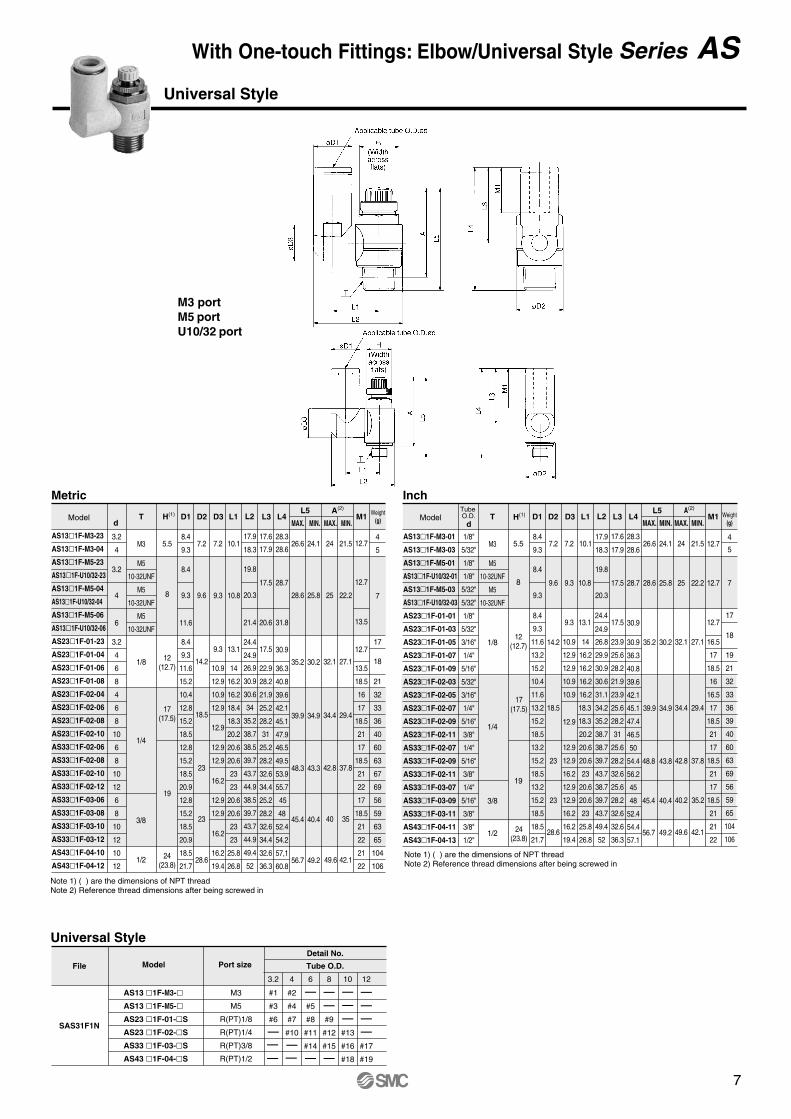
Minimizes installationtime and costReduce the mounting height and enablescompact machinery design. Effective area is larger than the former model.
Nylon, Soft nylon and Polyurethane tubing
Application to inch size tubing
Operating pressure1MPa max.
Applicable tube material
In-line style
Number of needle rotations hasbeen increased (8 to 10 turns)The increased number of needle rotations(8 to 10 turns) permits easy control at low speed.
Retainer prevents accidentalloss of needleOptional:Hexagonal lock nut,Nickel plated option
Model
Model
Applicable tube O.D.
Metric size Inch size
AS1001F
AS2001F
AS2051F
AS3001F
AS4001F
6, 10, 16, 20
20, 25, 32
20, 25, 32, 40
40, 50, 63
63, 80, 100
18"3.2 4 6 8 10 12 5
32"3
16"1
4" 516"
38" 1
2"
How to Order
1F 12 K400AS
M51/81/43/81/2
100200205300400
Body size
With One-touch fittings
Proof pressure
Max. operating pressure
Min. operating pressure
Ambient and fluid temperature
Number of needle rotations
Applicable tubes(2)
Option
1.5MPa
1MPa
0.1MPa
–5 to 60°C (No freezing)
10 turns (8 turns(1))
Nylon, Soft nylon, Polyurethane
Hexagonal lock nut, Nickel plated(3)
Specifications
Model
Metric size
Inch sizeApplicabletube O.D.
Controlled (Free) Flow
AS3001FAS2051F AS4001F
ø12
ø1/2"
1390
21
ø10
ø3/8"
1050
16
ø6
ø1/4
420
6.5
ø8
ø5/16
660
10
ø10, ø12
ø3/8"
920
14
ø6
ø3/16"
290
4.5
ø8
ø1/4, ø5/16
460
7
AS2001F
ø4
ø5/32"
130
2
ø6
ø3/16", ø1/4"
230
3.5
AS1001F
ø3.2, ø4, ø6
ø1/8", ø5/32"
100
1.5
Air Flow/Effective Area
Note 1) AS1001FNote 2) Pay attention to the maximum operating pressure when soft nylon or polyurethane is used.
(Refer to p. 7-146 and 7-147 in "Best Pneumatics for further information.)Note 3) Brass parts are all electroless nickel plated.
Note) Supply pressure: 0.5MPa, Temperature: 20°C.
Metric size (Release bushing: White color)ø3.2, ø4, ø6, ø8, ø10, ø12
Applicablecylinder bore size
(mm)
Applicable tube O.D.
ø3.2∗
ø4ø6ø8ø10ø12
Metric size
230406081012
ø1/8"ø5/32"ø3/16"ø1/4"
ø5/16"ø3/8"ø1/2"
Inch size
∗Use ø1/8" tubing.
01030507091113
JIS Symbol
Note) : Nickel plated model is standard.
Series ASIn-line Style
Speed Controller with One-touch Fittings
Inch size (Release bushing: Orange color)ø1/8", ø5/32", ø3/16", ø1/4", ø5/16", ø3/8", ø1/2"
Air flow(l/min(ANR))Effective area
(mm2)

11
Needle Valve/Flow Characteristic
Needle rotation (Turns) Needle rotation (Turns)
Needle rotation (Turns) Needle rotation (Turns)
Needle rotation (Turns)
Supply pressure: 0.5MPa
Supply pressure: 0.5MPa Supply pressure: 0.5MPa
Supply pressure: 0.5MPa Supply pressure: 0.5MPa
Flo
w (l/m
in (
AN
R))
Flo
w (l/m
in (
AN
R))
Flo
w (l/m
in (
AN
R))
Flo
w (l/m
in (
AN
R))
Flo
w (l/m
in (
AN
R))
Effe
ctiv
e ar
ea (
mm
2 )E
ffect
ive
area
(m
m2 )
Effe
ctiv
e ar
ea (
mm
2 )E
ffect
ive
area
(m
m2 )
Effe
ctiv
e ar
ea (
mm
2 )
With One-touch Fittings: In-line Style Series AS

12
Construction
Component PartsNo.q
w
e
r
t
y
u
i
o
!0
!1
DescriptionBody AHandleBody BNeedleNeedle guideLock nutU-packingSpacerCassettePackingO ring
PBTPBT
BrassBrassBrass
Brass(1)
NBR Brass(2)
POM, Stainless steelNBRNBR
Electroless nickel platedElectroless nickel platedElectroless nickel platedElectroless nickel plated
Material Note
Metric
82 11.3
13.5
12.7
13.5
17
18
17
18
21
22
21
22
12.710
11.8
19.8
26.5
14.8
ModelWeightTube
O.D.d
D1 D2 L1 L2 M1L3
MAX. MIN. (g)
Inch
AS1001F-23
AS1001F-04
AS1001F-06
AS2001F-04
AS2001F-06
AS2051F-06
AS2051F-08
AS3001F-06
AS3001F-08
AS3001F-10
AS3001F-12
AS4001F-10
AS4001F-12
3.2
4
6
4
6
6
8
6
8
10
12
10
12
8.4
9.3
11.6
9.3
11.6
12.8
15.2
12.8
15.2
18.5
20.9
18.5
20.9
38.0
39.2
40.7
40.7
44.8
53.2
59.8
59
64.4
71.6
76
4.5
5.2
6.2
5.2
6.3
6.7
8.1
7.4
8.2
9.8
11
23.5
24.2
25.2
32.6
33.7
35.2
36.5
38.3
39.1
40.6
41.8
51.1
52.1
20.7
21.4
22.4
27.6
28.7
30.2
31.5
33.3
34.1
35.6
36.8
43.6
44.6
6
7
8
12
13
26
31
18
21
32
33
36
40
AS1001F-01
AS1001F-03
AS2001F-03
AS2001F-05
AS2001F-07
AS2051F-05
AS2051F-07
AS2051F-09
AS3001F-07
AS3001F-09
AS3001F-11
AS4001F-11
AS4001F-13
1/8"
5/32"
5/32"
3/16"
1/4"
3/16"
1/4"
5/16"
1/4"
5/16"
3/8"
3/8"
1/2"
8.4
9.3
9.3
11.4
13.2
11.4
13.2
15.2
13.2
15.2
17.9
17.9
21.7
38
39.2
40.7
50
52.2
52.2
54.4
59.8
59
64.4
70.8
76.9
83.1
4.5
5.2
5.2
6.2
7.1
6.2
7.1
8.1
7.4
8.2
9.5
10.3
11.6
23.5
24.2
32.6
33.6
34.5
34.6
35.5
36.5
38.3
39.1
40.3
51
52.4
20.7
21.4
27.6
28.6
29.5
29.6
30.5
31.5
33.3
34.1
35.3
43.5
44.9
6
7
12
18
21
24
26
31
42
46
53
97
106
12.7
16.5
17
16.5
17
18
17
18
21
21
22
12.710
11.8
19.8
26.5
14.8
ModelWeight
D1 D2 L1 L2 M1L3
MAX. MIN. (g)
Note 1) AS2 1F: SteelNote 2) ø3.2, ø4, ø6, ø1/8", ø5/32" (Except for AS3001F-006): POM
Applicable tube O.D.ød
øD
1
M1
L1
M1
L3
øD2
In-line Style
AS1001F-AS2001F-AS2051F-AS3001F-AS4001F-
SAS01F1N
#1 #2
#4
#3
#5
#6
#8#7
#9 #11
#13
3.2 4 6 8 10 12
#10
#12
Model
Detail No.
Tube O.D.
Tube O.D.
d
File
____ _
__
_ _ ____
__
__
L2
Series AS
13
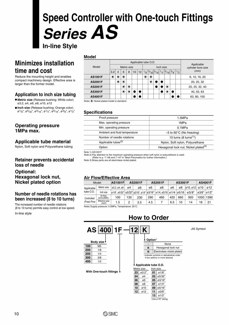
Ambient temperature
Material
Applicable tube
–20 to 60°C
Polypropylene
WhiteColor
Accessory: Round head Phillips screw for mounting (Black zinc chromated).
Specifications
Dimensions
Correspondence of In-line Speed Controller and Holder
Metric
Model Size(nominal X height) Piece
1
Metric InchTMH-23JTMH-04JTMH-06JTMH-06
TMH-10TMH-12
TMH-01JTMH-03JTMH-05TMH-07TMH-09TMH-11TMH-13
Model
Metric Inch
TMH-23JTMH-04J
TMH-06JTMH-06 TMH-08 TMH-10
TMH-12
AS1001FAS2001FAS2051FAS3001FAS4001F
TMH-01JTMH-03JTMH-05
TMH-07 TMH-09
TMH-11
TMH-13
ø3.2TMH-23J
TMH-04J TMH-06J
TMH-06 TMH-08
TMH-10 TMH-12
ø4 ø6 ø8 ø10 ø1223 04 06 08 10 12
øD2øD1 H1 H2 H3 H4 H5 L1 L2 L3 Symbol
8.49.3
11.711.613.113.515.518.518.821.222
1/8J1/32J3/16
61/48
5/16103/8121/2
M3 X 15
M4 X 25
M4 X 35
M3 X 20
3.3
3.3
4.3
4.3
4.5
6.3
7.1
9.5
4.6
6.4
7.2
9.6
7.5
9.3
11
14
6
7.7
10
14
12
15.4
20
28
7.2
8.5
11
14.2
6.6
8.3
10.6
14.6
18
21
26.5
34
Body size
Tube size
Applicable tube
Inch
AS1001FAS2001FAS2051FAS3001FAS4001F
ø1/8" ø5/32" ø3/16" ø1/4" ø5/16" ø3/8" ø1/2"01 03 05 07 09 11 13
TMH-01JTMH-03J
TMH-05TMH-07
TMH-09
TMH-11TMH-13
Body size
Tube size
TMH-08
Note 1) Mounting bracket is not available. This is an application example.
Series TMHHolder
A holder for securing a speed controller (in-line style) with aOne-touch fitting.
Universal mounting
The holder can be used to securean individual part.
Adaptable for a manifoldapplication.(1)
Can be mounted to a panel.
Construction
Component PartsNo.q
w
e
r
t
y
u
i
o
!0
!1
DescriptionBody AHandleBody BNeedleNeedle guideLock nutU-packingSpacerCassettePackingO ring
PBTPBT
BrassBrassBrass
Brass(1)
NBR Brass(2)
POM, Stainless steelNBRNBR
Electroless nickel platedElectroless nickel platedElectroless nickel platedElectroless nickel plated
Material Note
Metric
82 11.3
13.5
12.7
13.5
17
18
17
18
21
22
21
22
12.710
11.8
19.8
26.5
14.8
ModelWeightTube
O.D.d
D1 D2 L1 L2 M1L3
MAX. MIN. (g)
Inch
AS1001F-23
AS1001F-04
AS1001F-06
AS2001F-04
AS2001F-06
AS2051F-06
AS2051F-08
AS3001F-06
AS3001F-08
AS3001F-10
AS3001F-12
AS4001F-10
AS4001F-12
3.2
4
6
4
6
6
8
6
8
10
12
10
12
8.4
9.3
11.6
9.3
11.6
12.8
15.2
12.8
15.2
18.5
20.9
18.5
20.9
38.0
39.2
40.7
40.7
44.8
53.2
59.8
59
64.4
71.6
76
4.5
5.2
6.2
5.2
6.3
6.7
8.1
7.4
8.2
9.8
11
23.5
24.2
25.2
32.6
33.7
35.2
36.5
38.3
39.1
40.6
41.8
51.1
52.1
20.7
21.4
22.4
27.6
28.7
30.2
31.5
33.3
34.1
35.6
36.8
43.6
44.6
6
7
8
12
13
26
31
18
21
32
33
36
40
AS1001F-01
AS1001F-03
AS2001F-03
AS2001F-05
AS2001F-07
AS2051F-05
AS2051F-07
AS2051F-09
AS3001F-07
AS3001F-09
AS3001F-11
AS4001F-11
AS4001F-13
1/8"
5/32"
5/32"
3/16"
1/4"
3/16"
1/4"
5/16"
1/4"
5/16"
3/8"
3/8"
1/2"
8.4
9.3
9.3
11.4
13.2
11.4
13.2
15.2
13.2
15.2
17.9
17.9
21.7
38
39.2
40.7
50
52.2
52.2
54.4
59.8
59
64.4
70.8
76.9
83.1
4.5
5.2
5.2
6.2
7.1
6.2
7.1
8.1
7.4
8.2
9.5
10.3
11.6
23.5
24.2
32.6
33.6
34.5
34.6
35.5
36.5
38.3
39.1
40.3
51
52.4
20.7
21.4
27.6
28.6
29.5
29.6
30.5
31.5
33.3
34.1
35.3
43.5
44.9
6
7
12
18
21
24
26
31
42
46
53
97
106
12.7
16.5
17
16.5
17
18
17
18
21
21
22
12.710
11.8
19.8
26.5
14.8
ModelWeight
D1 D2 L1 L2 M1L3
MAX. MIN. (g)
Note 1) AS2 1F: SteelNote 2) ø3.2, ø4, ø6, ø1/8", ø5/32" (Except for AS3001F-006): POM
Applicable tube O.D.ød
øD
1
M1
L1
M1
L3
øD2
In-line Style
AS1001F-AS2001F-AS2051F-AS3001F-AS4001F-
SAS01F1N
#1 #2
#4
#3
#5
#6
#8#7
#9 #11
#13
3.2 4 6 8 10 12
#10
#12
Model
Detail No.
Tube O.D.
Tube O.D.
d
File
____ _
__
_ _ ____
__
__
L2

14
Model
Specifications
Dual Speed Controller with One-touch Fittings
Series ASD
Air Flow/Effective Area
ASD230F-M5ASD330F-01ASD430F-02ASD530F-02ASD530F-03ASD630F-04ASD230F-U10/32ASD330F-N01ASD430F-N02ASD530F-N02ASD530F-N03ASD630F-N04
M5
R(PT)1/8
R(PT)1/4
R(PT)1/4
R(PT)3/8
R(PT)1/2
10-32 UNF
NPT1/8
NPT1/4
NPT1/4
NPT3/8
NPT1/2
Model Port size
Applicable tube O.D.Metric Inch
ø4
•ø6
•••••
ø8
••••
ø10
••••
ø12
••••
ø1/8"
•
ø5/32"
•
ø3/16"
•
ø1/4"
••••
ø5/16"
••••
ø3/8"
••••
Proof pressure
Max. operating pressure
Min. operating pressure
Ambient and fluid temperature
Needle rotation cycles
Tube material (2)
Option
1.5MPa
1MPa
0.1MPa
–5 to 60°C (No freezing)
10 turns (8 turns (1))
Nylon, Soft nylon, Polyurethane
Hexagon lock nut
Note 1) In case of ASD230F.Note 2) Be careful with the max operating pressure for soft nylon and Polyurethane. (Refer to p. 7-146 and 7-147 in the catalog).
Note 1) Max. operating pressure: 0.5MPa, Temperature: 20°C
Model
Tube O.D.
Controlled (free)/Flow
Metric
Inch
Air flow (l/min(ANR))
Eff. area (mm2)
ASD230F ASD330F ASD430F ASD530F ASD630F
ø4, ø6
75
1.1
ø6, ø8
175
2.7
ø6
–
295
4.5
ø8, ø10
ø1/8"ø5/32"
ø3/16"ø1/4"
ø1/4"ø5/16"ø3/8"
350
5.3
ø6 ø8 ø10, ø12 ø10 ø12
ø1/4" ø5/16" ø3/8" – ø3/8"
500 600 700 1200 1300
7.6 9.1 10.7 18.3 19.8
Enables bi-directional flow control.Unrestricted 360° tube mounting direction.
JIS symbol
Symbol indication of flowdirection on the body
Meter-out Meter-in
Sym
bol
JIS
Sym
bol

15
How to Order
ASD 3
23456
M5 standard1/8 standard1/4 standard3/8 standard1/2 standard
Body size
Style
With One-touch fittings
Thread
3 Universal
Meter thread (M5)
Unified thread (10-32 UNF)
R(PT)
NPT
Port size
With sealant
Options
M5U10/32
01020304
M510-32UNF1/81/43/81/2
KNone
Hexagon lock nut
Applicable tubing O.D.Millimeter Inch
0406081012
ø4ø6ø8
ø10ø12
010305070911
ø1/8"ø5/32"ø3/16"ø1/4"ø5/16"ø3/8"
Needle Valve/Flow Characteristics
ASD230F ASD330F ASD430F
ASD530F ASD630F
100
50
05 10
1.5
1.0
0.5
0
Needle rotation (Turns)
Flo
w (
l/min
(A
NR
))
Effe
ctiv
e ar
ea (
mm
2 )
200
0 5 10
3
2
1
0
Needle rotation (Turns)
Flo
w (
l/min
(A
NR
))
Effe
ctiv
e ar
ea (
mm
2 )
100
400
0 5 10
6
4
2
0
Needle rotation (Turns)
Flo
w (
l/min
(A
NR
))
Effe
ctiv
e ar
ea (
mm
2 )
100
200
30006
07, 08, 09, 10, 11
1500
0 5 10
20
15
10
0
Flo
w (
l/min
(A
NR
))
Effe
ctiv
e ar
ea (
mm
2 )
500
10, 1112
1000
5
Needle rotation (Turns)
05 10
14
108
0
Flo
w (
l/min
(A
NR
))
Effe
ctiv
e ar
ea (
mm
2 )
500
1000
2
Needle rotation (Turns)
12
64
06, 07
10, 11, 1208, 09
30F 01 06 S K
N
_
_
Dual Speed Controller with One-touch Fittings Series ASD

16
Dimensions/Metric
7.8
10.6
11
15.4
14
18.6
d T H D1 D2 D3 L1 L2 L3Model
ASD230F-M5-04
ASD230F-M5-06
ASD330F-01-06S
ASD330F-01-08S
ASD430F-02-06S
ASD430F-02-08S
ASD430F-02-10S
ASD530F-02-06S
ASD530F-02-08S
ASD530F-02-10S
ASD530F-02-12S
ASD530F-03-06S
ASD530F-03-08S
ASD530F-03-10S
ASD530F-03-12S
ASD630F-04-10S
ASD630F-04-12S
M5
R(PT)1/8
R(PT)1/4
R(PT)1/4
R(PT)3/8
R(PT)1/2
8
12
17
19
19
24
4
6
6
8
6
8
10
6
8
10
12
6
8
10
12
10
12
9.3
11.6
11.6
15.2
12.8
15.2
18.5
12.8
15.2
18.5
20.9
12.8
15.2
18.5
20.9
18.5
20.9
9.6
14.2
18.5
23
23
28.6
10
11.8
15
19.8
19.8
26.5
11.7
14
15.8
18
19.7
20.3
23.1
20.3
23.1
25.9
29.4
32.5
38.5
44.8
43.5
46.5
49.3
48.3
51.3
54.1
55.9
48.3
51.3
54.1
55.9
64.3
66.1
17.5
20.6
22.9
28.2
25.2
28.2
31
25.2
28.2
32.6
34.4
25.2
28.2
32.6
34.4
32.6
34.4
28.3
39.6
38.9
41.7
46.9
46.9
64.8
25.5
34.6
33.9
36.7
41.9
41.9
57.3
25
32.1
34.4
42.8
40
49.6
22.2
27.1
29.4
37.8
35
42.1
12.9
13.7
13.7
18.5
17
18.5
21
17
18.5
21
22
17
18.5
21
22
21
22
L4 L5 A1∗A2∗ M
MAX. MIN. MAX. MAX.MIN. MIN.
Weight(g)
Applicable tube O.D.ød
L2
L3
M
L4L
1
L5 A1
A2
øD
3
øD
1
T
øD2
∗Reference dimensions of M5, R(PT) thread after being screwed in.
ASD230F
Metric
12
13
29
31
53
55
58
74
76
80
83
74
93
98
101
177
179
Applicable tube O.D. ød
L2
L3
M
L1
L4
H
T
L5 A
1A
2
øD
3
øD
1
øD2
ASD330F/430FASD530F/630F
(Widthacross flats)
H(Width
across flats)
28.6
35.2
39.9
48.3
45.4
56.7
25.8
30.2
34.9
43.3
40.4
49.2
Series ASD

17
∗Reference dimensions of M5, R(PT) thread after being screwed in.
Applicable tube O.D. ød
L2
L3
M
L4L
1
H
L5 A1
A2
øD
3
øD
1
T
øD2
ASD230FApplicable tube O.D. ød
L2
L3
M
L1
L4
H
T
L5 A
1A
2
øD
3
øD
1
øD2
ASD330F/430FASD530F/630F
Dimensions/Inch
(Widthacross flats)
(Widthacross flats)
10-32UNF
NPT 1/8
NPT 1/4
NPT 1/4
NPT 3/8
NPT 1/2
7.8
10.6
11
15.4
14
18.6
d T H D1 D2 D3 L1 L2 L3Model
ASD230F-U10/32-01
ASD230F-U10/32-03
ASD230F-U10/32-05
ASD230F-U10/32-07
ASD330F-N01-05S
ASD330F-N01-07S
ASD330F-N01-09S
ASD430F-N02-07S
ASD430F-N02-09S
ASD430F-N02-11S
ASD530F-N02-07S
ASD530F-N02-09S
ASD530F-N02-11S
ASD530F-N03-07S
ASD530F-N03-09S
ASD530F-N03-11S
ASD630F-N04-11S
8
12.7
17.5
19
19
23.8
1/8"
5/32"
3/16"
1/4"
3/16"
1/4"
5/16"
1/4"
5/16"
3/8"
1/4"
5/16"
3/8"
1/4"
5/16"
3/8"
3/8"
8.4
9.3
11.4
12
11.6
13.2
15.2
13.2
15.2
18.5
13.2
15.2
18.5
13.2
15.2
18.5
9.6
14.2
18.5
23
23
28.6
10
11.8
15
19.8
19.8
26.5
11.7
14
15.8
18
19.7
20.3
23.1
20.3
23.1
25.9
29.4
39.5
42.2
44.8
43.9
46.5
49.3
48.7
51.3
54.1
48.7
51.3
54.1
64.3
17.5
23.9
25.6
28.2
25.6
28.2
31
25.6
28.2
32.6
25.6
28.2
32.6
28.3
39.6
38.9
41.7
46.9
46.9
64.8
25.5
34.6
33.9
36.7
41.9
41.9
57.3
25
32
34.6
43
40.3
49.6
22.2
27
29.6
38
35.3
42.1
12.9
16.5
17
18.5
17
18.5
21
17
18.5
21
17
18.5
21
L4 L5 A1∗A2∗ M
Max. Min. Max. Max.Min. Min.Weight
(g)
Inch Size
12
13
30
31
55
62
76
84
93
102
180
10-32UNF
8 9.6 10 11.7 28.3 25.5
28.6 25.8
25 22.235.2
32.6
23.3
20.7 7.8
16.5
13.5
15
1328.6
35.2
39.9
48.3
45.4
56.7
25.8
30.2
34.9
43.3
40.4
49.2
Dual Speed Controller with One-touch Fittings Series ASD

18
Construction
Component PartsNo. q
w
e
r
t
y
u
i
o
!0
Body AElbow bodyHandleBody BBody BNeedleSeat ringNeedle guideLock nutLock nut
MaterialPBTPBTPBT
BrassBrassBrassBrassBrass
Brass(3)
Brass(3)
Note
Electroless nickel platedElectroless nickel platedElectroless nickel platedElectroless nickel platedElectroless nickel platedElectroless nickel platedBlack zinc chromated
Description No.!1
!2
!3
!4
!5
!6
!7
!8
!9
@0
@1
MaterialNBRNBR
POM, Stainless steel(1)
NBRNBRNBRNBRNBRNBR
Stainless, NBRPOM, Brass(2)
NoteDescriptionU packingU packingCassettePackingO ringO ringO ringO ringO ringGasketSpacer
ASD230F only
Note 1) ø10, ø12, ø3/16", ø3/8": POM, Stainless steel and Brass (Electroless nickel plated)Note 2) ø3/16", ø1/4", ø3/8": Brass (Electroless nickel plated)Note 3) ASD330 F and 430F: Steel
!8 w @1 !4 !3
r i o e y !5 !6 !0
!7 @0 !1 q !2 t
r eo y !5 !6 q
!7 !0!1 i!2 tu
!8 w @1 !4 !3
ASD230F ASD330F/430FASD530F/630F
yi o e u r!9q
!6 !5 !7 !2 t !0!1
!8 w @1 !4 !3
ASD530F-02
Component Parts
Series ASD

19

20
Needle Valve/Flow Characteristics
AS1200-M3, AS1400-M3 AS120-M5, AS120-U10/32 AS220-01Supply pressure: 0.5MPa
Supply pressure: 0.5MPa Supply pressure: 0.5MPa Supply pressure: 0.5MPa
Supply pressure: 0.5MPa Supply pressure: 0.5MPa
Needle rotation (Turns)
Needle rotation (Turns) Needle rotation (Turns) Needle rotation (Turns)
Needle rotation (Turns) Needle rotation (Turns)
Effe
ctiv
e ar
ea (
mm
2 )E
ffect
ive
area
(m
m2 )
Effe
ctiv
e ar
ea (
mm
2 )
Effe
ctiv
e ar
ea (
mm
2 )
Effe
ctiv
e ar
ea (
mm
2 )
Effe
ctiv
e ar
ea (
mm
2 )
Flo
w
(l/m
in (
AN
R))
Flo
w (
l/min
(A
NR
))
Flo
w (
l/min
(A
NR
))
Flo
w (
l/min
(A
NR
))
Flo
w (
l/min
(A
NR
))
Flo
w (
l/min
(A
NR
))
AS220-02 AS320 AS420
0.3
10-32UNF
Minimizes installation time and costFittings and tubes are not necessarybecause this type screws directly into theactuator. Thus, piping labour and cost canbe eliminated.
Body swivels 360°Swivel type allows free setting of piping.
Speed can be accurately controlledeven at low speeds.
Constant speed control is possible.Retainer prevents accidental lossof needle
Port size
Applicable cylinder bore size (mm)
Proof pressure
Max. operating pressure
Min. operating pressure
Ambient and fluid temperature
Number of needle rotations
Option
Weight (g)
Controlled flow(Free flow)
Air flow (l/min(ANR))
Effective area (mm2)
AS1200-M3 AS1400-M3 AS12�0-M5 AS22�0-01 AS22�0-02 AS32�0-03 AS42�0-04
M5 1/8 1/4
20, 25, 32, 40
3/8
32, 40, 50, 63
1/2
6, 10, 15, 20, 25 80, 100
AS12�0-U10/32Specifications
SpecificationsModel
1.5MPa
1MPa
0.1MPa
–5 to 60°C (No freezing)
10 turns 10 turns8 turns
Sealant, Hexagonal lock nut, Nickel plated
18110664291063
20
0.3
1700
26
920
14
460
7
230
3.5
105
1.6Note 1) Supply pressure: 0.5MPa. Temperature: 20°C.Note 2) Meter-in type not available on AS1200-M3, AS1400-M3Note 3) Distinction between meter-out/meter-in types by appearance. They are distinguished by the lock nut. The meter-out types is electroless nickel plated, while the meter-in type is black zinc chromate plated.Note 4) AS1200, AS1400, AS22�0: Electroless nickel plated (N specification).
How to Order
01 SAS 2 2 0 0Body size
1234
M3, M5
1 8 ,
83
21
1 4
StyleDirect connection
elbow
Direct connectionflat elbow
2
4
Controlled
Thread
Meter-outMeter-in
01
Options
Port size
SKN
NoneSealant
∗Indicate symbols in alphabetical order if two options or more desired.
–
Symbol Port size
–
Symbol Cylinder side Tubing side
Metric thread (M3, M5) Unified thread (10-32UNF)
NPTN
Model
M3
M5U10/32
01020304
M3
M510-32UNF
1/81/43/81/2
AS1200-M3AS1400-M3
AS12�0-M5AS12�0-U10/32
AS22�0-01AS22�0-02AS32�0-03AS42�0-04
Hexagonal lock nutElectroless nickel plated
R(PT) Rc(PT)
M3
2.5, 4, 6
1.05MPa
0.7MPa
0.1MPa
Series ASMetal Body Elbow Style
Speed Controller Standard
AS3200-03
AS4200-04
AS2200-02AS3200-01
AS1200-05

21
Needle Valve/Flow Characteristics
AS1200-M3, AS1400-M3 AS120-M5, AS120-U10/32 AS220-01Supply pressure: 0.5MPa
Supply pressure: 0.5MPa Supply pressure: 0.5MPa Supply pressure: 0.5MPa
Supply pressure: 0.5MPa Supply pressure: 0.5MPa
Needle rotation (Turns)
Needle rotation (Turns) Needle rotation (Turns) Needle rotation (Turns)
Needle rotation (Turns) Needle rotation (Turns)
Effe
ctiv
e ar
ea (
mm
2 )E
ffect
ive
area
(m
m2 )
Effe
ctiv
e ar
ea (
mm
2 )
Effe
ctiv
e ar
ea (
mm
2 )
Effe
ctiv
e ar
ea (
mm
2 )
Effe
ctiv
e ar
ea (
mm
2 )
Flo
w
(l/m
in (
AN
R))
Flo
w (
l/min
(A
NR
))
Flo
w (
l/min
(A
NR
))
Flo
w (
l/min
(A
NR
))
Flo
w (
l/min
(A
NR
))
Flo
w (
l/min
(A
NR
))
AS220-02 AS320 AS420
0.3
Standard: Metal Body Elbow Style Series AS

22
AS1400-M3/Construction AS1200-M3, AS120-M5, AS220/320/420/ConstructionMeter out
AS1200-M3, M5, U10/32
Meter inAS1210-M5, U10/32 AS2210/3210/4210
No. Description Material Note
q
w
e
r
t
y
u
i
o
!0
!1
!2
Body B
Body A
Needle
Lock nut
Handle
U-packing
Needle guide
O ring
O ring
Steel ball
Gasket
Joint
Brass
Brass
Brass
Brass
Brass
NBR
Brass
NBR
NBR
Chromium bearing steel
PVC
Brass
Electroless nickel plated
Electroless nickel plated
Electroless nickel plated
Electroless nickel plated
Electroless nickel plated
Electroless nickel plated
Electroless nickel plated
No. Description Material Note
q
w
e
r
t
y
u
i
o
!0
!1
!22
!3
Body A
Handle
Body B
Needle
Needle guide
Seat ring
Lock nut
U-packing
O ring
O ring
O ring
Bush
O ring
Zinc alloy
Brass
Brass
Brass
Brass
Brass
NBR
NBR
NBR
NBR
PBT
NBR
PVC
NBR, Stainless steel
Electroless nickel plated
Electroless nickel plated
Electroless nickel plated
Electroless nickel plated
Electroless nickel plated(2)
Component Parts
Component Parts
!4 Gasket
01 to 04 type
01 to 04 type
M3 type
M5, U10/32 types
Note 1) AS220: SteelNote 2) Meter-in type: Black zinc chromated
Brass(1)
AS2200/3200/4200
Series AS

23
AS1400-M3/Dimensions
Dimensions
M3 M3 4.5 6.6 23.5 21.5 8 5 5 20.5 18.5
MAX. MIN. MAX. MIN.L1
L2 AL3H(1)T2T1 D1 D2Model
AS1200-M3
AS1200-M5
AS1200-U10/32
AS22�0-01
AS22�0-02
AS32�0-03
AS42�0-04
M5
10-32UNF
1/8
1/4
3/8
M5
10-32UNF
1/8
1/4
8 10 28.3 10.3 9 9 25 22.2
12(12.7)
17(17.5)
18
27.2
30
38.5
25.5
14.3
18
22.5
27.5
14.6
19.5
24.3
28.5
32.4
34.8
40.6
47.4
27.4
29.8
35.6
42.4
Note 1) ( ) are the dimensions of "NPT" thread.
M3
M3
1.9 5.5 2.7
2.7
13
2.5
3.8
19.5
(M
AX
.21.
5)
H
(Widthacross flats)
T2
T1
øD2
L1
�
D1
L3
L2
A
H
(Width across flats)
L2
A
L3øD2
T2
øD
1
T1
L1
1/2
3/8
1/2
19
24(23.8)
AS22�0/32�0/42�0
AS-1200-M3, AS12�0-M5, AS22�0, 32�0, 42�0/Dimensions
AS1200-M3AS12�0-M5
35.5
40.3
45.8
54.7
30.5
35.3
40.8
49.7
13.2
17.5
19.7
25.8
Standard: Metal Body Elbow Style Series AS

24
Compact size saves space.
Speed may be accurately controlled
even at low speeds.
Constant speed easily set.
Retainer prevents accidental loss
of needle.
AS1000-M3
AS1000-M5
AS2000-01
AS2000-02
AS3000-02
AS3000-03
AS4000-02
AS4000-03
AS4000-04
AS5000-02
AS5000-03
AS5000-04
ModelPortsize
Applicable cylinderbore size
(mm)Effective area
(mm2)Air flow
(l/min(ANR))Air flow
(l/min(ANR))
M3
M5
1/8
1/4
1/4
3/8
1/4
3/8
1/2
1/4
3/8
1/2
20
90
340
340
810
810
1,670
1,670
1,670
2,840
4,270
4,270
0.3
1.4
5.2
5.2
12.3
12.3
25.5
25.5
25.5
44
66
66
20
80
250
250
810
810
1,670
1,670
1,670
2,840
4,270
4,270
0.3
1.2
3.8
3.8
12.3
12.3
25.5
25.5
25.5
44
66
66
4.7
33
90
115
130
124
221
214
205
242
233
224
2.5, 4, 6
6, 10, 16, 20, 25
1.5MPa (1.05MPa)
1MPa (0.7MPa)
0.05MPa (0.1MPa)
–5 to 60°C (No freezing)
8 turns (10 turns)
Free flow Controlled flow
20, 25, 32, 40
32, 40, 50, 63
40, 50, 6380, 100
40, 50, 6380, 100
Note) Supply pressure: 0.5MPa, Temperature: 20°C.
Note 1) ( ): Values for AS1000.
Note) AS1000 with nipple: AS1000-M5-N
Specifications
AccessoriesDescription Part No. Applicable model
Body size12345
M3, M51/8, 1/4
3/81/21/2
M5AS 1 000Port size
Port size Applicable modelM3M501020304
M3M51/8 1/43/81/2
AS1000AS1000AS2000
AS2000, 3000, 4000, 5000AS3000, 4000, 5000
AS4000, 5000
Thread– M3, M5
NPTG (PF)
How to Order
M-5N AS1000 Nipple
NF
Model
Effective area(mm2)
Proof pressure (1)
Max. operating pressure (1)
Min. operating pressure (1)
Ambient and fluid temperature
Number of needle rotation (1)
Speed Controller StandardSeries ASIn-line Style
Weight(g)
E
Ordering source area code
E EuropeN North America
-Japan, Asia
Australia

25
AS1000-M3/Construction
AS1000-M5/Construction
No. Description Material Noteq
w
e
r
t
y
u
i
o
Body BBodyNeedleLock nutHandleU-packingNeedle guideO ringO ring
BrassBrassBrass
NBRBrassNBRNBR
Electroless nickel platedElectroless nickel platedElectroless nickel platedElectroless nickel platedElectroless nickel plated
Electroless nickel plated4.5 X 3 X 0.752.2 X 0.8 X 0.7
Component Parts
No. Description Materialt
y
u
i
Valve seatU-packingO ringGasket
BrassNBRNBRPVC
No. Description Materialq
w
e
r
Body Needle
Lock nut∗Nipple
Zinc alloyStainless steel
BrassStainless steel
Component Parts
∗Electroless nickel plated
Needle Valve/Flow Characteristics
AS1000-M3 AS1000-M5 AS2000
AS3000 AS4000 AS5000
Flo
w (l/m
in(A
NR
))
Needle rotation (Turns)
20
15
10
5
0
0.3
0.2
0.1
80
60
40
20
1.2
0.9
0.6
0.3
02 4 6 8 10
Brass Brass
Supply pressure: 0.5MPa
Flo
w (l/m
in(A
NR
))
Flo
w (l/m
in(A
NR
))
Flo
w (l/m
in(A
NR
))
Flo
w (l/m
in(A
NR
))
Flo
w (l/m
in(A
NR
))
Supply pressure: 0.5MPa Supply pressure: 0.5MPa
Supply pressure: 0.5MPa
Supply pressure: 0.5MPa Supply pressure: 0.5MPa
Effe
ctiv
e ar
ea (
mm
2 )
Effe
ctiv
e ar
ea (
mm
2 )
Effe
ctiv
e ar
ea (
mm
2 )
Effe
ctiv
e ar
ea (
mm
2 )
Effe
ctiv
e ar
ea (
mm
2 )
Effe
ctiv
e ar
ea (
mm
2 )
Needle rotation (Turns) Needle rotation (Turns)
Needle rotation (Turns) Needle rotation (Turns)Needle rotation (Turns)
2 4 6 8 10
0 2 4 6 8
250
200
150
100
50
0
1.5
1.0
0.5
0
800
600
400
200
12
10
8
6
4
2
0
1,500
1,000
500
0 1 2 3 4 5 6 7 8
25
20
15
10
5
0
5000
4000
3000
2000
1000
00 1 2 3 4 5 6 7 8
70
60
50
40
30
20
10
0
3.5
3.02.5
2.0
8642
Standard: In-line Styte Series AS

26
AS4000/Construction
AS5000/Construction
AS2000, 3000/Construction
No. DescriptionModel
BodyNeedle∗Lock nut∗
ValveO ringSpring
Zinc alloyBrassBrass
Aluminum alloyBrass
Carbon steel
Component Parts
q
w
r
AS2000 AS3000
e
t
y
No. Description Material NoteBodyCapHead cap screwE type snap ringHandleRingLock nutNeedleO ring
Aluminum alloyRolled steelSteel wire
Stainless steelZinc
Steel wireZinc alloy
Aluminum alloyNBR
ChromatedZinc chromate4 X 0.7 X 8
JIS B2805 Nominal 6Chromated
Component Parts
∗Electroless nickel plated
q
w
e
r
t
y
u
i
!2
Zinc chromated
ValveSpringO ring
No. Description Material
Stainless steelNBR
NBR, Brasso
!0
!11
No. Description Material NoteBodyCapHead cap screwE type snap ringHandleRingLock nutNeedleO ring
Aluminum alloyRolled steelSteel wire
Stainless steelZinc alloy
Stainless steelZinc alloy
Aluminum alloyNBR
ChromatedNickel platedM4 X 8 Nickel plated
JIS B 2805 Nominal 6Chromated
Component Parts
q
w
e
r
t
y
u
i
!2
ChromatedChromated
JIS B2401 P12
ValveSpringPacking
No. Description Material
Stainless steelNBR
NBR, Stainless steelo
!0
!1
Series AS

27
AS1000-M3/Dimensions
AS2000·3000/Dimensions
AS1000-M5/Dimensions
AS4000/Dimensions
AS5000/Dimensions
Dimensions
MAX. MIN.L1 L2 L3 L4 L5 L6
L7L8 DModel Port size
AS2000-01AS2000-02AS3000-02, 03
404056
3030
45.5
55
5.25
172325
1011.513.2
15.517
20.6
54.55668
5051.561
162026
4.54.55.5
1 8
8, 31 4
1 4
M3
3.5
13
5.5
7.4
8
2-ø2.1
5.5
M3
L4
2-Port size
L8
L7
L5 L6
2-øDL3L2
L1
2-ø3.1
14
2027.5
Female M5
2-1/4 to1/2
63
31.533
29
49 7
2 X M4 Effective thread depth: 7
74.9
(MA
X.8
2.9)
2-1/4 to1/2 29.568
.5M
AX
76.5
67.529
34
2.7
19 (
MA
X.2
1)
12
Male M512
35 (
MA
X41
)
8
4.5
1518
2 X M4
50
34
19
Effective thread depth: 6
43
28
Standard: In-line Style Series AS

28
Constant speed easily set.Speed may be accurately controlledeven at low speeds.Retainer prevents accidental lossof needle.
AS420-02
AS420-03
AS420-04
AS500-06
AS600-10
AS800-12
AS900-14
AS900-20
ModelPortsize
Applicable cylinderbore size (mm)Effective area
(mm2)Effective area
(mm2)Air flow
(l/min (ANR))Air flow
(l/min (ANR))
Weight(kg)
2,500
5,000
6,600
10,100
15,100
35,400
52,000
57,800
38
77
100
154
230
540
792
880
3,600
4,800
6,700
8,100
16,900
38,500
47,500
60,800
55
74
102
123
258
586
724
926
0.36
0.7
1.4
3.3
3.3
63, 80, 100, 125
Free flow Controlled flow
160, 180, 200, 250
140, 160, 180, 200
Model
Note) Supply pressure: 0.5MPa, Temperature: 20°C.
300
0.34
0.33
0.32
1.5MPa
1MPa
0.05MPa
–5 to 60°C (No freezing)
10 turns (12 turns (1))Note 1) ( ): Values for AS800, AS900.
Proof pressure
Max. operating pressure
Min. operating pressure
Ambient and fluid temperature
Number of needle rotations
Specifications
Body size4250608090
AS 42 0Port size
Port size Applicable model0203040610121420
AS500AS600AS800
1/43/81/23/41
11/411/2
2
AS420
AS900Port thread– Rc(PT)
NPTPF
How to Order
Needle/Flow Characteristics
NF
02
1/4
3/8
1/2
3/4
1
11/411/2
2
1/23/41
11/411/2
Speed Controller StandardSeries ASLarge Flow In-line Style
E
Ordering source area code
E EuropeN North America
-Japan, Asia
Australia

29
q
w
e
r
q
w
e
r
t
t
y
u
i
NBR
No.
No.
DescriptionBody
NeedleBottom cover
Handle
DescriptionBody
Valve guideCheck valve
NeedleHandle
Check valveSpringO ringO ring
Aluminum alloyBrass
Aluminum alloyZinc
Chromated
ChromatedChromated
Material
Aluminum alloyAluminum alloy
BrassBrass
Carbon steel
Material
Note
ChromatedChromated
Rubber lining
Chromated
Note
BrassStainless steel
NBR NBRNBR
Stainless stee
O ringO ringpring
y
u
i
67.57490
1/4, 3/8, 1/23/41
AS420AS500AS600
384255
122115158
112105148
505062
Model
Model
L1Port size
Port size
L2 DMIN.
L3MAX.
1201501 , 2
AS800AS900
1 7493
204262
192250
8094
L1 L2 L4MIN.
L3MAX.
1 41 2
AS420, 500, 600/Construction
AS420, 500, 600/Dimensions AS800, 900/Dimensions
AS800, 900/Construction
Component Parts
Dimensions
Dimensions
Component Parts
Standard: Large Flow In-line Style Series AS

30
How to Order
ThreadRc(PT)
NPTG (PF)
–NF
Material for knobResinMetal
–2
1/43/8
0203
02AS3500
Specifications
Port size
Applicable cylinder bore size (mm)
Proof pressure
Max. operating pressure
Min. operating pressure
Ambient and fluid temperature
Number of needle rotations
Weight
Free flow
Controlledflow
Air flow (l/min(ANR))
Effective area (mm2)
Air flow (l/min(ANR))
Effective area (mm2)
40, 50, 63
1.5MPa
1MPa
0.05MPa
–5 to 60°C (No freezing)
8 turns
130g (Metallic handle: 140g)
810
12.3
810
12.3
Model Resin knob
Metal knob
Specifications
1/4 3/8
AS3500-02
AS3500-02-2
AS3500-03
AS3500-03-2
Note) Supply pressure: 0.5MPa, Temperature: 20°C.
Lock speed setting, with the touch of a buttonIt can be locked only by pushing the handleafter adjustment.
Convenient opening indication scaleThe opening indication scale for the needle valve isprovided on the handle to facilitate speed adjustments.
Easy speed control at low flow volume ranges
Possible to control the mass velocity
Constant knob constructed of metal towithstand heavy usageIn addition to the standard handle made of resin, aheavy-duty metal handle is also available.
Retainer prevents accidental loss of needle
Needle/Flow Characteristics AS3500
Metal knobResin knob
Speed Controller Standard
Series ASIn-line Push locking Style
Port size
JIS Symbol
E
Ordering source area code
E EuropeN North America
-Japan, Asia
Australia

31
Construction
Component PartsNo. Description NoteMaterial
BodyValveCapNeedle
q
w
e
r
t
y
Aluminum alloyNBR
Rolled steelBrassPOM
Zinc alloyNBR
Chromated
Electroless nickel plated
BlackBlack
O ring
25
1/4, 3/8
2-ø5.5 45.5
565.25 26
13.2
5
20.6
Handle
Dimensions
61.5
(MA
X.6
8.5)
Standard: In-line Push Locking Style Series AS

32
How to Order
Body size1/8, 1/4
3/81/2
234
Port sizeR(PT)1/8R(PT)1/4R(PT)3/8R(PT)1/2
01020304
Applicable tube O.D.0406081012
StyleElbow
Universal23
Controlled methodMeter-outMeter-in
01
With One-touch fittings
With residual pressure release valve
2 1 01 062AS 1 F E S K
AS221FE-01
AS221FE-02
AS321FE-03
AS421FE-04
1.5MPa
1.0MPa
0.1MPa
–5 to 60°C (No freezing)
10 turns
0.8mm2
Nylon, Soft nylon, Polyurethane
Elbow styleApplicable tube O.D (mm)
Note 1) Only elbow typeNotes) Distinction between meter-out/meter-in types by appearance They are distinguished by the lock nut. The meter-out types is electroless nickel plated, while the meter-in type is black zinc chromate plated.
Note) Supply pressure: 0.5MPa, Temperature: 20°C.
ø 4
AS231FE-01
AS231FE-02
AS331FE-03
AS431FE-04
R(PT)1/8
R(PT)1/4
R(PT)3/8
R(PT)1/2
20, 25, 32
20, 25, 32, 40
40, 50, 63
63, 80, 100
Universal styleCylinder
bore size (mm)Port size in
cylinder side
Model
Specifications
Residual pressure can be easilyreleased with one push of button.
Eye-catching red colour releasebutton.
ø 6 ø 8 ø10 ø12
AS221FE-01AS231FE-01
AS221FE-02AS231FE-02
AS321FEAS331FE
AS421FEAS431FE
Model
Tube O.D. Metric size ø4
180
2.7 3.5 4 6 7 10 12 14 24 26
230 260 390 460 660 790 920 1580 1710Controlled(Free)flow
Air flow (l/min(ANR))
Effective area (mm2)
Air Flow/Effective Area
ø4 ø6
ø4ø6ø8ø10ø12
ø8ø10
ø6 ø8 ø10 ø12ø12ø10ø6
ø8ø10
Sealant
Hexagonallock nut
Speed Controller with Residual Pressure Release Valve
Series ASFEWith One-touch Fittings
(1)
Proof pressure
Max. operating pressure
Min. operating pressure
Ambient and fluid temperature
Number of needle rotations
Effective area of residual pressure release valve
Applicable tubing
JIS Symbol
Indication of air flow direction on body

33
Needle Valve/Flow Characteristics
Needle rotation (Turns)
Supply pressure 0.5MPa
Flo
w (l/m
in (
AN
R))
Needle rotation (Turns) Needle rotation (Turns) Needle rotation (Turns)
Effe
ctiv
e ar
ea (
mm
2 )
Supply pressure 0.5MPa Supply pressure 0.5MPa
Supply pressure 0.5MPa
Effe
ctiv
e ar
ea (
mm
2 )
Effe
ctiv
e ar
ea (
mm
2 )
Flo
w (l/m
in (
AN
R))
Flo
w (l/m
in (
AN
R))
Effe
ctiv
e ar
ea (
mm
2 )
Flo
w (l/m
in (
AN
R))
AS2201FE-01, AS2211FE-01AS2301FE-01, AS2311FE-01
AS2201FE-02, AS2211FE-02AS2301FE-02, AS2311FE-02
AS3201FE, AS3211FEAS3301FE, AS3311FE
AS4201FE, AS4211FEAS4301FE, AS4311FE
With Residual Pressure Release Valve Series AS FE

34
Construction
Universal styleMeter-out
Meter-in Meter-in
No. Description Material Noteq
w
e
r
t
y
u
i
o
!0
!1
!2
!3
!4
!5
!6
!7
!8
Body A
Body B
Needle
Seat ring
Lock nut
Handle
Push button
Cassette
U-packing
Packing
O ring
O ring
O ring
Valve core
Elbow body
O ring
Jumping out preventing screw
Spacer
PBT
Brass
Brass
Brass
Brass
Aluminum alloy
POM
POM,Stainless steel
White
Electroless nickel plated
Electroless nickel plated
Electroless nickel plated(1)
Red painted
Red
Component Parts
NBR
NBR
NBR
NBR
NBR
NBR,Brass,Stainless steel
PBT
NBR
Stainless steel
POM
Note 1) Meter-in type: Black zinc chromated
note2)
Elbow styleMeter-out
Series ASFE

35
Dimensions
Elbow style
Dimensions
Universal style
Model Wgt.(g)T H1 H2 D1 D2 L1 L2 L3
L4 A∗M1
MAX. MIN.MAX. MIN.
AS221FE-01-04SK
AS221FE-01-06SK
AS221FE-01-08SK
AS221FE-01-10SK
AS221FE-02-04SK
AS221FE-02-06SK
AS221FE-02-08SK
AS221FE-02-10SK
AS321FE-03-06SK
AS321FE-03-08SK
AS321FE-03-10SK
AS321FE-03-12SK
AS421FE-04-10SK
AS421FE-04-12SK
4
6
8
10
4
6
8
10
6
8
10
12
10
12
9.3
11.6
15.2
18.5
10.4
12.8
15.2
18.5
12.8
15.2
18.5
20.9
18.5
20.9
20.4
20.4
25.3
33.1
25.2
25.2
27.2
33.9
27.8
29.5
31.9
32.8
33.6
34.6
27.5
27.5
32.4
40.2
34.4
34.4
36.4
43.2
39.3
41
43.3
44.3
47.9
48.9
12.7
13.5
18.5
21
16
17
18.5
21
16
18.5
21
22
21
22
26
27
29
31
36
37
39
42
57
60
62
64
103
105
1/8
1/4
3/8
1/2
12
17
19
24
12
14
14
17
14.2
28.6
23
18.5
49.9
46.2
51.5
56.5
44.9
41.2
46.5
51.5
∗Reference dimensions of R(PT) thread after being screwed in.
TubeO.D.
d
TubeO.D.
d
Wgt.(g)
T H1 H2 D1 D2 D3 L1 L2 L3 L4L5 A∗
M1MAX. MIN.MAX. MIN.
AS231FE-01-04SK
AS231FE-01-06SK
AS231FE-01-08SK
AS231FE-02-04SK
AS231FE-02-06SK
AS231FE-02-08SK
AS231FE-02-10SK
AS331FE-03-06SK
AS331FE-03-08SK
AS331FE-03-10SK
AS331FE-03-12SK
AS431FE-04-10SK
AS431FE-04-12SK
4
6
8
4
6
8
10
6
8
10
12
10
12
9.3
11.6
15.2
10.4
12.8
15.2
18.5
12.8
15.2
18.5
20.9
18.5
21.7
24.9
26.9
30.9
30.6
34
35.2
38.7
38.5
39.7
43.7
44.9
49.4
52
13.1
14
16.2
16.2
18.4
18.3
20.2
20.6
23
25.8
26.8
9.3
10.9
12.9
10.9
17.5
22.9
28.2
21.9
25.2
28.2
31
25.2
28.2
32.6
34.4
32.6
36.3
12.7
13.5
18.5
16
17
18.5
21
17
18.5
21
22
21
22
26
27
29
36
37
39
42
57
60
62
64
103
105
1/8
1/4
3/8
1/2
12
14
19
24
12
14
14
17
14.2
28.6
23
18.5
49.9
46.2
51.5
56.5
44.9
41.2
46.5
51.5
∗Reference dimensions of R(PT) thread after being screwed in.
16.2
19.4
16.2
12.9
12.9
Model
H1(Widthacross flats)
H2(Widthacross flats)
Applicable tube O.D. ød
øD2M1
L1
L2
T
øD
1
AL4
Applicable tube O. D. ød
H1 (Width across flats)H2 (Width across flats)øD1
A
L5
L1
L 2
øD
3
TøD2
L4
L3
M1
L3
13.4
14.1
17.7
19.5
19.8
24.5
53
51.7
56.7
63.8
48
46.7
51.7
58.8
53
30.9
36.3
40.8
39.6
42.1
45.1
47.9
45
48
52.4
54.2
57.1
60.8
51.7
56.7
63.8
48
46.7
51.7
58.8
With Residual Pressure Release Valve Series ASFE

36
E
340 5.2 250 3.8
Residual pressure can be easilyreleased with one push of button.
Model/Air Flow, Effective Area
Eye-catching red colour releasebutton.
AS2000E-01
AS2000E-02
AS3000E-02
AS3000E-03
AS4000E-02
AS4000E-03
AS4000E-04
ModelPort size Applicable
cylinder bore size(mm)
Effectivearea
(mm2)
Effectivearea
(mm2)
Weight(g)
Rc(PT)1/8
Rc(PT)1/4
Rc(PT)1/4
Rc(PT)3/8
Rc(PT)1/4
Rc(PT)3/8
Rc(PT)1/2
Controlled flow
20, 25, 32, 40
32, 40, 50, 63
40, 50, 6380, 100
Free flow
Air flow(l/min(ANR))
Air flow(l/min(ANR))
340
810
1670
12.3
25.5
810
1670
12.3
25.5
90
115
130
225
Note) Supply pressure: 0.5MPa, Temperature: 20°C.
1.5MPa
1.0MPa
0.05MPa
–5 to 60°C (No freezing)
8 turns
0.8mm2
Proof pressure
Max. operating pressure
Min. operating pressure
Ambient and fluid temperature
Number of needle rotations
Effective area of residual exhaust valve
Specifications
Body size234
1/8, 1/43/81/2
01AS 2 000
Port size
With residual pressure release valve
Port size Applicable series01020304
Rc(PT)1/8Rc(PT)1/4Rc(PT)3/8Rc(PT)1/2
AS2000EAS2000E, 3000E, 4000E
AS3000E, 4000EAS4000E
How to Order
Speed Controller with Residual Pressure Release Valve
Series ASEStandard

37
Needle Valve/Flow Characteristics
Construction
AS2000E/3000E AS4000E
No. DescriptionModel
AS2000 AS3000
q
w
e
r
t
y
u
Body
Needle
Lock nut
Valve core
Handle
Push button
Cap
Zinc alloy
Brass
Brass_
Alluminum alloy
Brass
Brass_
POM (Red)
Stainless steel
Aluminum alloy (Red painted)
POM (Red)
Stainless steel
Aluminum alloy (Red painted)
Component Parts
No. Description Material
i
o
!0
!1
Valve
Spring
NBR
Stainless steel
Stainless steel
NBR
Cross-recessed head cap screw
O ring
No. Description NoteMaterial
q
w
e
r
t
y
u
i
Component Parts
Aluminum alloy
SPC
Zinc alloy
Spring steel
Zinc alloy
Alluminum alloy
NBR/Stainless steel
POM
Chromated
Nickel plated
Chromated, Red
Zinc chromated
Chromated
Chromated
Red
Body
Cap
Handle
Ring
Lock nut
Needle
Valve
Push button
No. Description Material
o
!0
!1
!2
NBR/ Brass
Stainless steel
NBR
Steel wire
Valve
Spring
O ring
Cross-recessed head cap screw
AS2000E
Flo
w (l/m
in(A
NR
))
250
200
150
100
50
0 2 4 6 8
Effe
ctiv
e ar
ea (
mm
2 )
3.5
3.0
2.5
2.0
1.5
1.0
0.5
Needle rotation (Turns)
AS3000E
800
600
400
200
0
2
4
6
8
12
10
86420
AS4000E
1.500
500
0 2 4 6 8
25
20
15
10
5
Supply pressure: 0.5 MPa Supply pressure: 0.5 MPa Supply pressure: 0.5 MPa
Flo
w (l/m
in(A
NR
))
Flo
w (l/m
in(A
NR
))
Effe
ctiv
e ar
ea (
mm
2 )
Effe
ctiv
e ar
ea (
mm
2 )
Needle rotation (Turns)
Needle rotation (Turns)
1.000
With Residual Pressure Release Valve Series ASE

38
Models
Flow Rate and Effective Area
AS12�1FG-M5
AS22�1FG-01
AS22�1FG-02
AS32�1FG-02
AS32�1FG-03
AS42�1FG-04
AS12�1FG-U10/32
AS22�1FG-N01
AS22�1FG-N02
AS32�1FG-N02
AS32�1FG-N03
AS42�1FG-N04
AS13�1FG-M5
AS23�1FG-01
AS23�1FG-02
AS33�1FG-02
AS33�1FG-03
AS43�1FG-04
AS13�1FG-U10/32
AS23�1FG-N01
AS23�1FG-N02
AS33�1FG-N02
AS33�1FG-N03
AS43�1FG-N04
M5
R(PT) 1/8
R(PT) 1/4
R(PT) 1/4
R(PT) 3/8
R(PT) 1/2
10-32UNF
NPT1/8
NPT1/4
NPT1/4
NPT3/8
NPT1/2
6, 10, 16, 20
20, 25, 32
20, 25, 32, 40
40, 50, 63
40, 50, 63
63, 80, 100
6, 10, 16, 20
20, 25, 32
20, 25, 32, 40
40, 50, 63
40, 50, 63
63, 80, 100
Elbow type Universaltype
Port size
Applicable tube outside diameter Applicablecylinder
bore size(mm)
Metric size Inch size
3.2
�
�
4
�
�
�
6
�
�
�
�
�
8
�
�
�
�
10
�∗
�
�
�
�
12
�
�
�
1/8"
�
�
5/32"
�
�
�
3/16"
�
�
�
1/4"
�
�
�
�
�
5/16"
�
�
�
�
3/8"
�
�
�
�
1/2"
�
Model
TubeO.D.
Controlled (Free)
Metric size
Inch size
l /min (ANR)
Effective area mm²
AS12�1FG
AS13�1FG
AS22�1FG-�01
AS23�1FG-�01
AS22�1FG-�02
AS23�1FG-�02
AS32�1FG
AS33�1FG
AS42�1FG
AS43�1FG
100
1.5
ø3.2
ø4
ø6
ø1/8"
ø5/32"
ø3/16"
ø1/4"
ø3/16"
ø1/4"
ø5/16"
ø1/4"
ø5/16"
ø3/8"
ø1/8"
ø5/32"
ø5/32" ø3/16" ø1/4" ø5/16" ø3/8" ø3/8" ø1/2"
ø6
ø8
ø10
ø4 ø6 ø8
ø10
ø10
ø12
ø6 ø8 ø10 ø12ø3.2
ø4
180
2.7
230
3.5
260
4
390
6
460
7
660
10
790
12
920
14
1580
12
1710
26
Note 1) The meter-out and meter-in types can be visually determined by the flow direction symbol on the resin body.Note 2) ∗ Elbow type only
Note) The flow rate values are at a pressure of 0.5MPa and temperature of 20°C.
Elbow type
Universal type
Specifications
Proof pressure
Maximum operating pressure
Minimum operating pressure
Ambient & fluid temperature
Number of needle revolutions
Applicable tube material Note 2)
1.5MPa
1MPa
0.1MPa
–5 to 60°C (with no freezing)
10 revolutions ( 8 revolutions Note 1))
Nylon, Soft nylon, Polyurethane, Soft polyurethane
Note 1) For types AS12�1FG and AS13�1FGNote 2) Use caution regarding the maximum operating pressure with soft nylon, polyurethane and soft
polyurethane. (For details, refer to CAT.E501-B "Air Fittings and Tubing" pages 7-146 through 7-147.)
Flowrate
flow
Dimensions
AS2000E/3000E
AS4000E
AS2000E-01
AS2000E-02
AS3000E-02, 03
L7
MAX. MIN.L1 DL2 L3 L4 L5 L6 L8
40
40
56
30
30
45.5
5
5
5.25
17
23
25
10
12
13.25
15.5
17
20.6
61.5
63.5
76
57
59
69
16
20
26
4.5
4.5
5.5
Model
Rc(PT)1/8
Rc(PT)1/4
Rc(PT)1/4, 3/8
Port size
2-Rc(PT)1/4 to 1/2
72 (
MA
X.8
0)
2 X M4Length of effectivethread: 6
2- Port size
Series ASE

39
Models
Flow Rate and Effective Area
AS12�1FG-M5
AS22�1FG-01
AS22�1FG-02
AS32�1FG-02
AS32�1FG-03
AS42�1FG-04
AS12�1FG-U10/32
AS22�1FG-N01
AS22�1FG-N02
AS32�1FG-N02
AS32�1FG-N03
AS42�1FG-N04
AS13�1FG-M5
AS23�1FG-01
AS23�1FG-02
AS33�1FG-02
AS33�1FG-03
AS43�1FG-04
AS13�1FG-U10/32
AS23�1FG-N01
AS23�1FG-N02
AS33�1FG-N02
AS33�1FG-N03
AS43�1FG-N04
M5
R(PT) 1/8
R(PT) 1/4
R(PT) 1/4
R(PT) 3/8
R(PT) 1/2
10-32UNF
NPT1/8
NPT1/4
NPT1/4
NPT3/8
NPT1/2
6, 10, 16, 20
20, 25, 32
20, 25, 32, 40
40, 50, 63
40, 50, 63
63, 80, 100
6, 10, 16, 20
20, 25, 32
20, 25, 32, 40
40, 50, 63
40, 50, 63
63, 80, 100
Elbow type Universaltype
Port size
Applicable tube outside diameter Applicablecylinder
bore size(mm)
Metric size Inch size
3.2
�
�
4
�
�
�
6
�
�
�
�
�
8
�
�
�
�
10
�∗
�
�
�
�
12
�
�
�
1/8"
�
�
5/32"
�
�
�
3/16"
�
�
�
1/4"
�
�
�
�
�
5/16"
�
�
�
�
3/8"
�
�
�
�
1/2"
�
Model
TubeO.D.
Controlled (Free)
Metric size
Inch size
l /min (ANR)
Effective area mm²
AS12�1FG
AS13�1FG
AS22�1FG-�01
AS23�1FG-�01
AS22�1FG-�02
AS23�1FG-�02
AS32�1FG
AS33�1FG
AS42�1FG
AS43�1FG
100
1.5
ø3.2
ø4
ø6
ø1/8"
ø5/32"
ø3/16"
ø1/4"
ø3/16"
ø1/4"
ø5/16"
ø1/4"
ø5/16"
ø3/8"
ø1/8"
ø5/32"
ø5/32" ø3/16" ø1/4" ø5/16" ø3/8" ø3/8" ø1/2"
ø6
ø8
ø10
ø4 ø6 ø8
ø10
ø10
ø12
ø6 ø8 ø10 ø12ø3.2
ø4
180
2.7
230
3.5
260
4
390
6
460
7
660
10
790
12
920
14
1580
12
1710
26
Note 1) The meter-out and meter-in types can be visually determined by the flow direction symbol on the resin body.Note 2) ∗ Elbow type only
Note) The flow rate values are at a pressure of 0.5MPa and temperature of 20°C.
Elbow type
Universal type
Specifications
Proof pressure
Maximum operating pressure
Minimum operating pressure
Ambient & fluid temperature
Number of needle revolutions
Applicable tube material Note 2)
1.5MPa
1MPa
0.1MPa
–5 to 60°C (with no freezing)
10 revolutions ( 8 revolutions Note 1))
Nylon, Soft nylon, Polyurethane, Soft polyurethane
Note 1) For types AS12�1FG and AS13�1FGNote 2) Use caution regarding the maximum operating pressure with soft nylon, polyurethane and soft
polyurethane. (For details, refer to CAT.E501-B "Air Fittings and Tubing" pages 7-146 through 7-147.)
Flowrate
flow
Speed Controller with One-touch FittingStainless Steel SeriesElbow Type/Universal Type
Series AS-FG

40
How to Order
AS 2
1234
NilMetric thread (M5)
Unified thread (10-32UNF)R(PT)NPT
23
ElbowUniversal
NilS
NoneWith sealant ∗
Body size
Type
Option
M5 U10/32
01020304
M510-32UNF
1/81/43/81/2
23 04 06 08 10 12
ø3.2ø4ø6ø8
ø10ø12
01 03 05 07091113
ø1/8"ø5/32"ø3/16"ø1/4"ø5/16"ø3/8"ø1/2"
Needle Valve/Flow Rate Characteristics
AS12�1FGAS13�1FG
AS22�1FG-�01AS23�1FG-�01
AS22�1FG-�02AS23�1FG-�02
AS32�1FGAS33�1FG
AS42�1FGAS43�1FG
Thread type
01
N
Meter-outMeter-in
Control method
01,0
3,04
05,0
6,07
,08,
09,1
0
07,0
8,09
,10,
1105
,06
03,04
10,11,12
08,09
06,07
12,1310,11
113 F G 01 06
Stainless steel specification (SUS303)
∗ M5 and U10/32 are not available with sealant.
∗ Use a ø1/8" tube.
M5 standard1/8, 1/4 standard3/8 standard1/2 standard
Port size
Applicable tube outside diameterMetric size Inch size
With One-touch fittings
∗
Series AS-FG
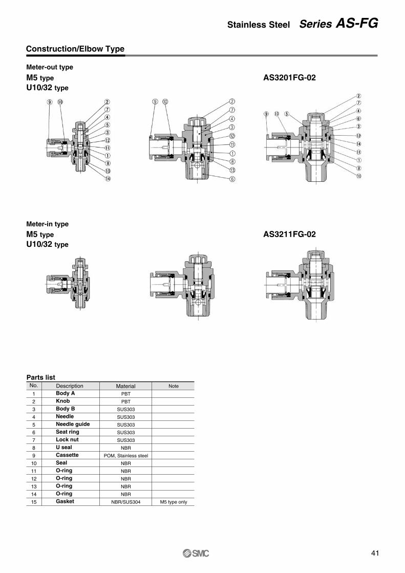
41
Construction/Elbow Type
Parts listNo. Description Material Note
M5 type only
1
2
3
4
5
6
7
8
9
10
11
12
13
14
15
PBT
PBT
SUS303
SUS303
SUS303
SUS303
SUS303
NBR
POM, Stainless steel
NBR
NBR
NBR
NBR
NBR
NBR/SUS304
Meter-out type
Meter-in type
M5 typeU10/32 type
AS3201FG-02
M5 typeU10/32 type
AS3211FG-02
Body AKnobBody BNeedleNeedle guideSeat ringLock nutU sealCassetteSealO-ringO-ringO-ringO-ringGasket
How to Order
AS 2
1234
NilMetric thread (M5)
Unified thread (10-32UNF)R(PT)NPT
23
ElbowUniversal
NilS
NoneWith sealant ∗
Body size
Type
Option
M5 U10/32
01020304
M510-32UNF
1/81/43/81/2
23 04 06 08 10 12
ø3.2ø4ø6ø8
ø10ø12
01 03 05 07091113
ø1/8"ø5/32"ø3/16"ø1/4"ø5/16"ø3/8"ø1/2"
Needle Valve/Flow Rate Characteristics
AS12�1FGAS13�1FG
AS22�1FG-�01AS23�1FG-�01
AS22�1FG-�02AS23�1FG-�02
AS32�1FGAS33�1FG
AS42�1FGAS43�1FG
Thread type
01
N
Meter-outMeter-in
Control method
01,0
3,04
05,0
6,07
,08,
09,1
0
07,0
8,09
,10,
1105
,06
03,04
10,11,12
08,09
06,07
12,1310,11
113 F G 01 06
Stainless steel specification (SUS303)
∗ M5 and U10/32 are not available with sealant.
∗ Use a ø1/8" tube.
M5 standard1/8, 1/4 standard3/8 standard1/2 standard
Port size
Applicable tube outside diameterMetric size Inch size
With One-touch fittings
∗
Stainless Steel Series AS-FG

42
Construction/Universal Type
Meter-out type
Meter-in type
Parts ListNo. Description Material Note1
2
3
4
5
6
7
8
9
10
11
12
13
14
15
16
17
18
PBT
PBT
PBT
SUS303
SUS303
SUS303
SUS303
SUS303
NBR
POM, Stainless steel
NBR
NBR
NBR
NBR
NBR
NBR
POM Note 1)
NBR, Stainless steel
Note 1) ø3/16", ø3/8" and ø1/2" are SUS303.
M5 typeU10/32 type
M5 typeU10/32 type
AS3301FG-02
AS3311FG-02
Body AElbow bodyKnobBody BNeedleNeedle guideSeat ringLock nutU sealCassetteSealO-ringO-ringO-ringO-ringO-ringSpacerGasket
Series AS-FG

43
Dimensions/Elbow Type
Metric size
Model d TWeight
gH D1 D2 L1 L2 L3L4 A ∗
Max. Min. Max. Min.M1 M1
AS12�1FG-M5-23
AS22�1FG-01-23
AS12�1FG-M5-04
AS12�1FG-M5-06
AS22�1FG-01-04
AS22�1FG-01-06
AS22�1FG-01-08
AS22�1FG-01-10
AS22�1FG-02-04
AS22�1FG-02-06
AS22�1FG-02-08
AS22�1FG-02-10
AS32�1FG-02-06
AS32�1FG-02-08
AS32�1FG-02-10
AS32�1FG-02-12
AS32�1FG-03-06
AS32�1FG-03-08
AS32�1FG-03-10
AS32�1FG-03-12
AS42�1FG-04-10
AS42�1FG-04-12
3.2
3.2
4
6
4
6
8
10
4
6
8
10
6
8
10
12
6
8
10
12
10
12
8.4
9.3
9.3
11.6
9.3
11.6
15.2
18.5
10.4
12.8
15.2
18.5
12.8
15.2
18.5
20.9
12.8
15.2
18.5
20.9
18.5
20.9
22.1
27.5
22.1
22.9
27.5
27.5
32.4
40.2
34.4
34.4
36.4
43.2
39.3
41
43.3
44.3
39.3
41
43.3
44.3
47.9
48.9
17.3
20.4
17.3
18.1
20.4
20.4
25.3
33.1
25.2
25.2
27.2
33.9
27.8
29.5
31.8
32.8
27.8
29.5
31.8
32.8
33.6
34.6
12.7
12.7
12.7
13.5
12.7
13.5
18.5
21
16
17
18.5
21
17
18.5
21
22
17
18.5
21
22
21
22
7
16
7
17
19
21
32
34
36
60
63
67
69
55
57
59
61
100
101
22.2
27.1
22.2
27.1
29.4
37.8
35.2
42.1
9.6
14.2
9.6
14.2
18.5
23
23
28.6
8
12
8
12
17
19
19
24
M5
M5 25
32.1
25
32.1
34.4
42.8
40.2
49.6
R(PT)1/4
R(PT)1/4
R(PT)3/8
R(PT)1/2
R(PT)1/8
R(PT)1/8
Inch size
Model d TWeight
gH D1 D2 L1 L2 L3L4 A ∗
Max. Min. Max. Min.
AS12�1FG-U10/32-01
AS12�1FG-U10/32-03
AS12�1FG-U10/32-05
AS12�1FG-U10/32-07
AS22�1FG-N01-01
AS22�1FG-N01-03
AS22�1FG-N01-05
AS22�1FG-N01-07
AS22�1FG-N01-09
AS22�1FG-N02-03
AS22�1FG-N02-05
AS22�1FG-N02-07
AS22�1FG-N02-09
AS22�1FG-N02-11
AS32�1FG-N02-07
AS32�1FG-N02-09
AS32�1FG-N02-11
AS32�1FG-N03-07
AS32�1FG-N03-09
AS32�1FG-N03-11
AS42�1FG-N04-11
AS42�1FG-N04-13
1/8"
5/32"
3/16"
1/4"
1/8"
5/32"
3/16"
1/4"
5/16"
5/32"
3/16"
1/4"
5/16"
3/8"
1/4"
5/16"
3/8"
1/4"
5/16"
3/8"
3/8"
1/2"
8.4
9.3
11.4
12
9.3
11.4
13.2
15.2
10.4
11.4
13.2
15.2
17.9
13.2
15.2
17.9
13.2
15.2
17.9
17.9
21.7
7
16
17
19
21
32
34
36
60
63
67
55
57
59
100
101
12.7
16.5
13.5
12.7
16.5
18.5
21
16
17
18.5
21
17
18.5
21
17
18.5
21
21
22
9.6
14.2
18.5
23
23
28.6
8
12.7
17.5
19
19
23.8
25
32.1
34.4
42.8
40.2
49.6
22.1
26.1
23.1
27.5
30.2
31
32.4
34.4
34.2
34.5
36.4
43.2
39.3
41
43.3
39.3
41
43.3
47.9
49.5
17.3
21.3
18.3
20.4
23.1
23.9
25.3
25.2
24.9
25.2
27.2
33.9
27.8
29.5
31.8
27.8
29.5
31.8
33.6
35.2
NPT1/4
NPT1/4
NPT3/8
NPT1/2
NPT1/8
10-32UNF
M5 typeU10/32 type
22.2
27.1
29.4
37.8
35.2
42.1
∗ Reference dimensions for threads after installation. ∗ Reference dimensions for 10-32UNF and NPT threads after installation.
12.3
14.3
12.3
11.7
13.4
14.1
19.7
19.5
21.3
19.8
24.5
28.6
36.1
28.6
35.2
40.1
48.3
45.4
56.7
25.8
31.1
25.8
30.2
35.1
43.3
40.4
49.2
25.8
30.2
34.9
43.3
40.4
49.2
12.3
11.7
13.4
14.1
17.7
19.5
21.3
19.8
24.5
28.6
35.2
39.9
48.3
45.4
56.7
Stainless Steel Series AS-FG

44
Dimensions/Universal Type
Metric size
Model d TWeight
gH D1 D2 L1 L2 L3L5 A ∗
Max. Min. Max. Min.M1
AS13�1FG-M5-23
AS13�1FG-M5-04
AS13�1FG-M5-06
AS23�1FG-01-23
AS23�1FG-01-04
AS23�1FG-01-06
AS23�1FG-01-08
AS23�1FG-02-04
AS23�1FG-02-06
AS23�1FG-02-08
AS23�1FG-02-10
AS33�1FG-02-06
AS33�1FG-02-08
AS33�1FG-02-10
AS33�1FG-02-12
AS33�1FG-03-06
AS33�1FG-03-08
AS33�1FG-03-10
AS33�1FG-03-12
AS43�1FG-04-10
AS43�1FG-04-12
3.2
4
6
3.2
4
6
8
4
6
8
10
6
8
10
12
6
8
10
12
10
12
8.4
9.3
11.6
8.4
9.3
11.6
15.2
10.4
12.8
15.2
18.5
12.8
15.2
18.5
20.9
12.8
15.2
18.5
20.9
18.5
20.9
19.8
20.3
21.4
24.4
24.9
26.9
30.9
30.6
34
35.2
38.7
38.5
39.7
43.7
44.9
38.5
39.7
43.7
44.9
49.4
52
10.8
13.1
14
16.2
16.2
18.4
18.3
20.2
20.6
23
20.6
23
25.8
26.8
12.7
13.5
12.7
13.5
18.5
16
17
18.5
21
17
18.5
21
22
17
18.5
21
22
21
22
7
17
18
21
32
33
36
40
60
63
67
69
56
59
63
65
104
105
9.6
14.2
18.5
23
23
28.6
D3
9.3
9.3
10.9
12.9
10.9
12.9
12.9
16.2
12.9
16.2
16.2
19.4
8
12
17
19
19
24
M5 22.2
27.1
29.4
37.8
35
42.1
25
32.1
34.4
42.8
40
49.6
L4
17.5
20.6
17.5
22.9
28.2
21.9
25.2
28.2
31
25.2
28.2
32.6
34.4
25.2
28.2
32.6
34.4
32.6
36.3
R(PT)1/4
R(PT)1/4
R(PT)3/8
R(PT)1/2
R(PT)1/8
Inch size
For M5 typeFor U10/32 type
Model d Tweight
gH D1 D2 L1 L2 L3L5 A ∗
Max. Min. Max. Min.M1
AS13�1FG-U10/32-01
AS13�1FG-U10/32-03
AS13�1FG-U10/32-05
AS13�1FG-U10/32-07
AS23�1FG-N01-01
AS23�1FG-N01-03
AS23�1FG-N01-05
AS23�1FG-N01-07
AS23�1FG-N01-09
AS23�1FG-N02-03
AS23�1FG-N02-05
AS23�1FG-N02-07
AS23�1FG-N02-09
AS23�1FG-N02-11
AS33�1FG-N02-07
AS33�1FG-N02-09
AS33�1FG-N02-11
AS33�1FG-N03-07
AS33�1FG-N03-09
AS33�1FG-N03-11
AS43�1FG-N04-11
AS43�1FG-N04-13
1/8"
5/32"
3/16"
1/4"
1/8"
5/32"
3/16"
1/4"
5/16"
5/32"
3/16"
1/4"
5/16"
3/8"
1/4"
5/16"
3/8"
1/4"
5/16"
3/8"
3/8"
1/2"
8.4
9.3
11.4
12
8.4
9.3
11.4
13.2
15.2
10.4
11.4
13.2
15.2
17.9
13.2
15.2
17.9
13.2
15.2
17.9
17.9
21.7
19.8
20.3
21.3
21.6
24.4
24.9
26.8
29.9
30.9
30.6
31.1
34.2
35.2
38.7
38.7
39.7
43.7
38.7
39.7
43.7
49.4
52
10.8
13.1
14
16.2
16.2
18.3
20.2
20.6
23
20.6
23
25.8
26.8
12.7
16.5
13.7
12.7
16.5
18.5
21
16
17
18.5
21
17
18.5
21
17
18.5
21
21
22
7
8
17
18
19
21
32
33
36
39
40
60
63
69
56
59
65
104
106
D3
9.3
9.3
10.9
12.9
10.9
12.9
12.9
16.2
12.9
16.2
16.2
19.4
9.6
14
19
23
23
29
8
12.7
17.5
19
19
23.8
10-32UNF 22.2
27.1
29.4
37.8
35.2
42.1
25
32.1
34.4
42.8
40.2
49.6
L4
17.5
23.3
20.7
17.5
23.9
25.6
28.2
21.9
23.9
25.6
28.2
31
25.6
28.2
32.6
25.6
28.2
32.6
32.6
36.3
NPT1/4
NPT1/4
NPT3/8
NPT1/2
NPT1/8
∗ Reference dimensions for M5 and R(PT) threads after installation.
∗ Reference dimensions for 10-32UNF and NPT threads after installation.
25.8
30.2
34.9
43.3
40.4
49.2
28.6
35.2
39.9
48.3
45.4
56.7
28.7
31.8
30.9
36.3
40.8
39.6
42.1
45.1
47.9
46.5
49.5
53.9
55.7
45
48
52.4
54.2
57.1
60.8
25.8
30.2
34.9
43.3
40.4
49.2
28.6
35.2
39.9
48.3
45.4
56.7
28.7
34.5
31.9
30.9
36.3
40.8
39.6
42.1
45.1
47.9
46.5
46.9
49.5
53.9
45
48
52.4
54.4
57.1
Series AS-FG

45
Models
Specifications
Flow Rate and Effective Area
AS1001FG
AS2001FG
AS2051FG
AS3001FG
AS4001FG
6, 10, 16, 20
20, 25, 32
20, 25, 32, 40
40, 50, 63
63, 80, 100
Model
Applicable tube outside diameter Applicablecylinder
bore size(mm)
Metric size Inch size
3.2 4 6 8 10 12 1/8" 5/32" 3/16" 1/4" 5/16" 3/8" 1/2"
Proof pressure
Maximum operating pressure
Minimum operating pressure
Ambient and fluid temperature
Number of needle revolutions
Applicable tube material Note 2)
1.5MPa
1MPa
0.1MPa
–5 to 60°C (with no freezing)
10 revolutions (8 revolutions Note 1))
Nylon, Soft nylon, Polyurethane, Soft polyurethane
Note 1) For AS1001FG typeNote 2) Use caution regarding the maximum operating pressure with soft nylon, polyurethane and soft polyurethane. (For details, refer to CAT.E501-B "Air Fittings and Tubing" pages 7-146 through 7-147.)
Model
Tube O.D.
Metric size
Inch size
Effective area mm²
AS1001FG AS2001FG AS2051FG AS3001FG AS4001FG
100
1.5
ø3.2
ø4
ø6
ø1/8"
ø5/32"
ø3/16"
ø3/16"
ø1/4"
ø1/4"
ø5/16"
ø5/32" ø3/16" ø1/4" ø5/16" ø3/8" ø3/8" ø1/2"
ø6 ø6 ø8 ø10
ø12
ø6 ø8 ø10 ø12ø4
130
2
230
3.5
290
4.5
460
7
420
6.5
660
10
920
14
1050
16
1390
21
Note) Flow rate values are at a pressure of 0.5MPa and a temperature of 20°C.
l /min (ANR)Flowrate
Controlled (Free)
flow
Speed Controller with One-touch FittingStainless Steel SeriesIn-line Type
Series AS-FG

46
How to Order
AS 200
100200205300400
M5 standard1/8 standard1/4 standard3/8 standard1/2 standard
Body size Applicable tube outside diameterMetric size Inch size
230406081012
ø3.2ø4ø6ø8
ø10ø12
01030507091113
ø1/8"ø5/32"ø3/16"ø1/4"ø5/16"ø3/8"ø1/2"
Needle Valve/Flow Rate Characteristics
1 F G 06
Stainless steel specification (SUS303)
With One-touch fitting∗ Use a ø1/8" tube.
∗
Series AS-FG

47
Construction
Metric size
Dimensions
Model d Weightg
D1 D2 L1 L2L3
Max. Min.M1
AS1001FG-23
AS1001FG-04
AS1001FG-06
AS2001FG-04
AS2001FG-06
AS2051FG-06
AS2051FG-08
AS3001FG-06
AS3001FG-08
AS3001FG-10
AS3001FG-12
AS4001FG-10
AS4001FG-12
3.2
4
6
4
6
6
8
6
8
10
12
10
12
8.4
9.3
11.6
9.3
11.6
12.8
15.2
12.8
15.2
18.5
20.9
18.5
20.9
4.5
5.2
6.2
5.2
6.3
6.7
8.1
7.4
8.2
9.8
11
11.3
38
39.2
40.7
40.7
44.8
53.2
59.8
59
64.4
71.6
76
82
12.7
13.5
12.7
13.5
17
18
17
18
21
22
21
22
6
7
8
12
13
26
31
18
21
32
33
36
40
10
11.8
14.8
19.8
26.5
20.7
21.4
22.4
27.6
28.7
30.2
27.6
33.3
34.1
35.6
36.8
43.6
44.6
23.5
24.2
25.2
32.6
33.7
35.2
32.6
38.3
39.1
40.6
41.8
51.1
52.1
Model d Weightg
D1 D2 L1 L2L3
Max. Min.M1
AS1001FG-01
AS1001FG-03
AS1001FG-05
AS1001FG-07
AS2001FG-03
AS2001FG-05
AS2001FG-07
AS2051FG-05
AS2051FG-07
AS2051FG-09
AS3001FG-07
AS3001FG-09
AS3001FG-11
AS4001FG-11
AS4001FG-13
1/8"
5/32"
3/16"
1/4"
5/32"
3/16"
1/4"
3/16"
1/4"
5/16"
1/4"
5/16"
3/8"
3/8"
1/2"
8.4
9.3
11.4
12
9.3
11.4
13.2
11.4
13.2
15.2
13.2
15.2
17.9
17.9
21.7
4.5
5.2
6.2
5.2
6.2
7.1
6.2
7.1
8.1
7.4
8.2
9.5
10.3
11.6
38
39.2
48.7
40.7
40.7
50
52.2
52.2
54.4
59.8
59
64.4
70.8
76.9
83.1
12.7
16.5
13.7
12.7
16.5
17
16.5
17
18
17
18
21
21
22
6
7
8
9
12
18
21
24
26
31
42
46
53
97
106
10
11.8
14.8
19.8
26.5
20.7
21.4
22.4
27.6
28.6
29.5
29.6
30.5
27.6
33.3
34.1
35.3
43.5
44.9
23.5
24.2
25.2
32.6
33.6
34.5
34.6
35.5
32.6
38.3
39.1
40.3
51
52.4
Inch size
Parts listNo. Description Material Note
1
2
3
4
5
6
7
8
9
10
11
PBT
PBT
SUS303
SUS303
SUS303
SUS303
NBR
POM Note 1)
POM, Stainless steel
NBR
NBR
Note) ø3/16", ø3/8" and ø1/2" are SUS303.
Body AKnobBody BNeedleNeedle guideLock nutU sealSpacerCassetteSealO-ring
How to Order
AS 200
100200205300400
M5 standard1/8 standard1/4 standard3/8 standard1/2 standard
Body size Applicable tube outside diameterMetric size Inch size
230406081012
ø3.2ø4ø6ø8
ø10ø12
01030507091113
ø1/8"ø5/32"ø3/16"ø1/4"ø5/16"ø3/8"ø1/2"
Needle Valve/Flow Rate Characteristics
1 F G 06
Stainless steel specification (SUS303)
With One-touch fitting∗ Use a ø1/8" tube.
∗
Stainless Steel Series AS-FG

48
ASD230FG-M5
ASD330FG-01
ASD430FG-02
ASD530FG-02
ASD530FG-03
ASD630FG-04
ASD230FG-U10/32
ASD330FG-N01
ASD430FG-N02
ASD530FG-N02
ASD530FG-N03
ASD630FG-N04
M5 x 0.8
R(PT) 1/8
R(PT) 1/4
R(PT) 1/4
R(PT) 3/8
R(PT) 1/2
10-32 UNF
NPT 1/8
NPT 1/4
NPT 1/4
NPT 3/8
NPT 1/2
Model Port size
Applicable tube outside diameter
Metric size Inch size
4 6 8 10 12 1/8" 5/32" 3/16" 1/4" 5/16" 3/8"
Note 1) For ASD230FG typeNote 2) Use caution regarding the maximum operating pressure with soft nylon, polyurethane and soft polyurethane. (For details, refer to CAT.E501-B "Air Fittings and Tubing" pages 7-146 through 7-147.)
Note 1) Flow rate values are at a pressure of 0.5MPa and a temperature of 20°C.
Model
Tube O.D.
Metric size
Inch size
Effective area mm²
ASD230FG ASD330FG ASD430FG ASD530FG ASD630FGø4, ø6
75
1.1
ø6, ø8
175
2.7
ø6
––
295
4.5
ø8, ø10
ø1/8"ø5/32"
ø3/16"ø1/4"
ø1/4"ø5/16"ø3/8"
350
5.3
ø6 ø8 ø10, ø12 ø10 ø12
ø1/4" ø5/16" ø3/8" –– ø3/8"
500
7.6
600
9.1
700
10.7
1200
18.3
1300
19.8
JIS symbol
Flow direction symbols on body
Meter-out type Meter-in type
Sym
bol
JIS
sym
bol
Models
Specifications
Flow Rate and Effective Area
Proof pressure
Maximum operating pressure
Minimum operating pressure
Ambient & fluid temperature
Number of needle revolutions
Applicable tube material Note 2)
1.5MPa
1MPa
0.1MPa
–5 to 60°C (with no freezing)
10 revolutions (8 revolutions Note 1))
Nylon, Soft nylon, Polyurethane, Soft polyurethane
Two flow control valves and check valves have been integrated.
Pop out prevention and speed control of single acting cylinder.
Stable speed control can be achieved even with load fluctuations.
l /min (ANR)Flowrate Controlled
(Free)flow
Dual Speed Controller with One-touch FittingStainless Steel Series
Series ASD-FG

49
How to Order
ASD 3
23456
M5 standard1/8 standard1/4 standard3 /8 standard1/2 standard
Body size
Type
With One-touch fitting
Stainless steel specification(SUS303)
Thread type
3 Universal
NilMetric threads (M5)
Unified threads (10-32UNF)R(PT)NPT
Port size
With sealant∗ M5 and U10/32 are not available with sealant.
M5U10/32
01020304
M510-32UNF
1/81/43/81/2
Applicable tube outside diameterMetric size Inch size
0406081012
ø4ø6ø8
ø10ø12
010305070911
ø1/8"ø5/32"ø3/16"ø1/4"ø5/16"ø3/8"
Needle Valve/Flow Rate Characteristics
ASD230FG ASD330FG ASD430FG
ASD530FG ASD630FG
100
50
05 10
1.5
1.0
0.5
0
Number of needle revolutions
Flo
w r
ate
l/m
in (
AN
R)
Effe
ctiv
e ar
ea m
m²
200
05 10
3
2
1
0
100
400
05 10
6
4
2
0
Number of needle revolutions
Flo
w r
ate
l/m
in (
AN
R)
Effe
ctiv
e ar
ea m
m²
100
200
300 06
07, 08, 09, 10, 11
1500
05 10
20
15
10
0
500
10, 11
12
1000
5
05 10
14
10
8
0
500
1000
2
12
6
4
06, 07
10, 11, 1208, 09
30FG 01 06 S
N
Number of needle revolutions
Flo
w r
ate
l /m
in (
AN
R)
Effe
ctiv
e ar
ea m
m²
Number of needle revolutions
Flo
w r
ate
l /m
in (
AN
R)
Effe
ctiv
e ar
ea m
m²
Number of needle revolutions
Flo
w r
ate
l/m
in (
AN
R)
Effe
ctiv
e ar
ea m
m²
ASD230FG-M5
ASD330FG-01
ASD430FG-02
ASD530FG-02
ASD530FG-03
ASD630FG-04
ASD230FG-U10/32
ASD330FG-N01
ASD430FG-N02
ASD530FG-N02
ASD530FG-N03
ASD630FG-N04
M5 x 0.8
R(PT) 1/8
R(PT) 1/4
R(PT) 1/4
R(PT) 3/8
R(PT) 1/2
10-32 UNF
NPT 1/8
NPT 1/4
NPT 1/4
NPT 3/8
NPT 1/2
Model Port size
Applicable tube outside diameter
Metric size Inch size
4 6 8 10 12 1/8" 5/32" 3/16" 1/4" 5/16" 3/8"
Note 1) For ASD230FG typeNote 2) Use caution regarding the maximum operating pressure with soft nylon, polyurethane and soft polyurethane. (For details, refer to CAT.E501-B "Air Fittings and Tubing" pages 7-146 through 7-147.)
Note 1) Flow rate values are at a pressure of 0.5MPa and a temperature of 20°C.
Model
Tube O.D.
Metric size
Inch size
Effective area mm²
ASD230FG ASD330FG ASD430FG ASD530FG ASD630FGø4, ø6
75
1.1
ø6, ø8
175
2.7
ø6
––
295
4.5
ø8, ø10
ø1/8"ø5/32"
ø3/16"ø1/4"
ø1/4"ø5/16"ø3/8"
350
5.3
ø6 ø8 ø10, ø12 ø10 ø12
ø1/4" ø5/16" ø3/8" –– ø3/8"
500
7.6
600
9.1
700
10.7
1200
18.3
1300
19.8
JIS symbol
Flow direction symbols on body
Meter-out type Meter-in type
Sym
bol
JIS
sym
bol
Models
Specifications
Flow Rate and Effective Area
Proof pressure
Maximum operating pressure
Minimum operating pressure
Ambient & fluid temperature
Number of needle revolutions
Applicable tube material Note 2)
1.5MPa
1MPa
0.1MPa
–5 to 60°C (with no freezing)
10 revolutions (8 revolutions Note 1))
Nylon, Soft nylon, Polyurethane, Soft polyurethane
Two flow control valves and check valves have been integrated.
Pop out prevention and speed control of single acting cylinder.
Stable speed control can be achieved even with load fluctuations.
l /min (ANR)Flowrate Controlled
(Free)flow
Stainless Steel Series ASD-FG

50
Construction
Parts listNo.
1
2
3
4
5
6
7
8
9
10
11
Material
PBT
PBT
PBT
SUS303
SUS303
SUS303
SUS303
SUS303
SUS303
SUS303
NBR
NoteDescription No.
12
13
14
15
16
17
18
19
20
21
Material
NBR
POM, Stainless steel
NBR
NBR
NBR
NBR
NBR
NBR
NBR, Stainless steel
POM Note1)
Note
M5 type only
Description
Note 1) ø3/16", ø3/8" and ø1/2" are SUS303.
ASD230FG ASD330FG/430FGASD530FG/630FG
ASD530FG-02
Body AElbow bodyKnobBody BBody BNeedleSeat ringNeedle guideLock nutLock nutU seal
U sealCassetteSealO-ringO-ringO-ringO-ringO-ringGasketSpacer
Series ASD-FG
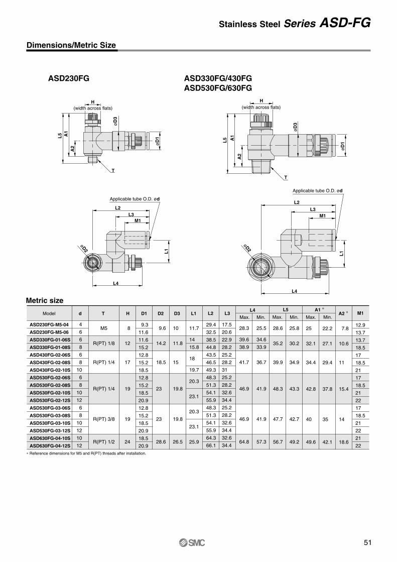
51
Dimensions/Metric Size
7.8
10.6
11
15.4
14
18.6
d T H D1 D2 D3 L1 L2 L3Model
ASD230FG-M5-04
ASD230FG-M5-06
ASD330FG-01-06S
ASD330FG-01-08S
ASD430FG-02-06S
ASD430FG-02-08S
ASD430FG-02-10S
ASD530FG-02-06S
ASD530FG-02-08S
ASD530FG-02-10S
ASD530FG-02-12S
ASD530FG-03-06S
ASD530FG-03-08S
ASD530FG-03-10S
ASD530FG-03-12S
ASD630FG-04-10S
ASD630FG-04-12S
M5
R(PT) 1/8
R(PT) 1/4
R(PT) 1/4
R(PT) 3/8
R(PT) 1/2
8
12
17
19
19
24
4
6
6
8
6
8
10
6
8
10
12
6
8
10
12
10
12
9.3
11.6
11.6
15.2
12.8
15.2
18.5
12.8
15.2
18.5
20.9
12.8
15.2
18.5
20.9
18.5
20.9
9.6
14.2
18.5
23
23
28.6
10
11.8
15
19.8
19.8
26.5
11.7
14
15.8
18
19.7
20.3
23.1
20.3
23.1
25.9
29.4
32.5
38.5
44.8
43.5
46.5
49.3
48.3
51.3
54.1
55.9
48.3
51.3
54.1
55.9
64.3
66.1
17.5
20.6
22.9
28.2
25.2
28.2
31
25.2
28.2
32.6
34.4
25.2
28.2
32.6
34.4
32.6
34.4
28.3
39.6
38.9
41.7
46.9
46.9
64.8
25.5
34.6
33.9
36.7
41.9
41.9
57.3
25
32.1
34.4
42.8
40
49.6
22.2
27.1
29.4
37.8
35
42.1
12.9
13.7
13.7
18.5
17
18.5
21
17
18.5
21
22
17
18.5
21
22
21
22
L4 L5 A1 ∗A2 ∗ M1
Max. Min. Max. Max.Min. Min.
L2L3
M1
L4
L1
H
L5 A1
A2
øD
3
øD
1
T
øD2
ASD230FG
Metric size
Applicable tube O.D. ød
Applicable tube O.D. ødL2
L3M1
L1
L4
H
T
L5 A1
A2
øD
3
øD
1
øD2
ASD330FG/430FGASD530FG/630FG
∗ Reference dimensions for M5 and R(PT) threads after installation.
(width across flats)(width across flats)
28.6
35.2
39.9
48.3
47.7
56.7
25.8
30.2
34.9
43.3
42.7
49.2
Construction
Parts listNo.
1
2
3
4
5
6
7
8
9
10
11
Material
PBT
PBT
PBT
SUS303
SUS303
SUS303
SUS303
SUS303
SUS303
SUS303
NBR
NoteDescription No.
12
13
14
15
16
17
18
19
20
21
Material
NBR
POM, Stainless steel
NBR
NBR
NBR
NBR
NBR
NBR
NBR, Stainless steel
POM Note1)
Note
M5 type only
Description
Note 1) ø3/16", ø3/8" and ø1/2" are SUS303.
ASD230FG ASD330FG/430FGASD530FG/630FG
ASD530FG-02
Body AElbow bodyKnobBody BBody BNeedleSeat ringNeedle guideLock nutLock nutU seal
U sealCassetteSealO-ringO-ringO-ringO-ringO-ringGasketSpacer
Stainless Steel Series ASD-FG
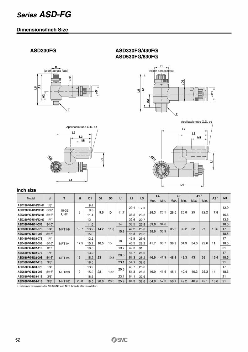
52
Dimensions/Inch Size
10-32UNF
NPT1/8
NPT1/4
NPT1/4
NPT3/8
NPT1/2
7.8
10.6
11
15.4
14
18.6
d T H D1 D2 D3 L1 L2 L3Model
ASD230FG-U10/32-01
ASD230FG-U10/32-03
ASD230FG-U10/32-05
ASD230FG-U10/32-07
ASD330FG-N01-05S
ASD330FG-N01-07S
ASD330FG-N01-09S
ASD430FG-N02-07S
ASD430FG-N02-09S
ASD430FG-N02-11S
ASD530FG-N02-07S
ASD530FG-N02-09S
ASD530FG-N02-11S
ASD530FG-N03-07S
ASD530FG-N03-09S
ASD530FG-N03-11S
ASD630FG-N04-11S
8
12.7
17.5
19
19
23.8
1/8"
5/32"
3/16"
1/4"
3/16"
1/4"
5/16"
1/4"
5/16"
3/8"
1/4"
5/16"
3/8"
1/4"
5/16"
3/8"
3/8"
8.4
9.3
11.4
12
11.6
13.2
15.2
13.2
15.2
18.5
13.2
15.2
18.5
13.2
15.2
18.5
18.5
9.6
14.2
18.5
23
23
28.6
10
11.8
15
19.8
19.8
26.5
11.7
14
15.8
18
19.7
20.3
23.1
20.3
23.1
25.9
29.4
35.2
32.6
38.5
42.2
44.8
43.9
46.5
49.3
48.7
51.3
54.1
48.7
51.3
54.1
64.3
17.5
23.3
20.7
23.9
25.6
28.2
25.6
28.2
31
25.6
28.2
32.6
25.6
28.2
32.6
32.6
28.3
39.6
38.9
41.7
46.9
46.9
64.8
25.5
34.6
33.9
36.7
41.9
41.9
57.3
25
32
34.6
43
40.3
46.9
22.2
27
29.6
38
35.3
42.1
12.9
16.5
13.5
16.5
17
18.5
17
18.5
21
17
18.5
21
17
18.5
21
21
L4 L5 A1 ∗A2 ∗ M1
Max. Min. Max. Max.Min. Min.
Inch size
Applicable tube O.D. ød
L2L3
M1
L4
L1
øD2
L2
L3M1
L1
L4
øD2
ASD230FG ASD330FG/430FGASD530FG/630FG
Applicable tube O.D. ød
∗ Reference dimensions for 10-32UNF and NPT threads after installation.
H
L5 A1
A2
øD
3
øD
1
T
H
T
L5 A1
A2
øD
3
øD
1
(width across flats) (width across flats)
28.6
35.2
39.9
48.3
45.4
56.7
25.8
30.2
34.9
43.3
40.4
49.2
Series ASD-FG

53
Dimensions/Inch Size
10-32UNF
NPT1/8
NPT1/4
NPT1/4
NPT3/8
NPT1/2
7.8
10.6
11
15.4
14
18.6
d T H D1 D2 D3 L1 L2 L3Model
ASD230FG-U10/32-01
ASD230FG-U10/32-03
ASD230FG-U10/32-05
ASD230FG-U10/32-07
ASD330FG-N01-05S
ASD330FG-N01-07S
ASD330FG-N01-09S
ASD430FG-N02-07S
ASD430FG-N02-09S
ASD430FG-N02-11S
ASD530FG-N02-07S
ASD530FG-N02-09S
ASD530FG-N02-11S
ASD530FG-N03-07S
ASD530FG-N03-09S
ASD530FG-N03-11S
ASD630FG-N04-11S
8
12.7
17.5
19
19
23.8
1/8"
5/32"
3/16"
1/4"
3/16"
1/4"
5/16"
1/4"
5/16"
3/8"
1/4"
5/16"
3/8"
1/4"
5/16"
3/8"
3/8"
8.4
9.3
11.4
12
11.6
13.2
15.2
13.2
15.2
18.5
13.2
15.2
18.5
13.2
15.2
18.5
18.5
9.6
14.2
18.5
23
23
28.6
10
11.8
15
19.8
19.8
26.5
11.7
14
15.8
18
19.7
20.3
23.1
20.3
23.1
25.9
29.4
35.2
32.6
38.5
42.2
44.8
43.9
46.5
49.3
48.7
51.3
54.1
48.7
51.3
54.1
64.3
17.5
23.3
20.7
23.9
25.6
28.2
25.6
28.2
31
25.6
28.2
32.6
25.6
28.2
32.6
32.6
28.3
39.6
38.9
41.7
46.9
46.9
64.8
25.5
34.6
33.9
36.7
41.9
41.9
57.3
25
32
34.6
43
40.3
46.9
22.2
27
29.6
38
35.3
42.1
12.9
16.5
13.5
16.5
17
18.5
17
18.5
21
17
18.5
21
17
18.5
21
21
L4 L5 A1 ∗A2 ∗ M1
Max. Min. Max. Max.Min. Min.
Inch size
Applicable tube O.D. ød
L2L3
M1
L4
L1
øD2
L2
L3M1
L1
L4
øD2
ASD230FG ASD330FG/430FGASD530FG/630FG
Applicable tube O.D. ød
∗ Reference dimensions for 10-32UNF and NPT threads after installation.
H
L5 A1
A2
øD
3
øD
1
T
H
T
L5 A1
A2
øD
3
øD
1
(width across flats) (width across flats)
28.6
35.2
39.9
48.3
45.4
56.7
25.8
30.2
34.9
43.3
40.4
49.2
Models
Specifications
Flow Rate and Effective Area
Port size
3.2
�
�
1/8"
�
�
5/32"
�
�
�
3/16"
�
�
�
5/16"
�
�
1/4"
�
�
�
3/8"
�
Applicable tube outside diameter
10
�
8
�
�
6
�
�
�
4
�
�
�
Proof pressure
Maximum operating pressure
Minimum operating pressure
Ambient and fluid temperature
Number of needle revolutions
Applicable tubing material Note 2)
Option Note 3)
1.5MPa
1.0MPa
0.1MPa
–5 to 60°C (with no freezing)
10 revolutions (20 revolutions Note 1))
Nylon, Soft nylon, Polyurethane, Soft polyurethane
With sealant
ø1/8", ø5/32", ø3/16"ø1/4"
ø3/16", ø1/4"ø5/16"
Tube O.D.
Controlledflow
Free flow
ø3.2, ø4
ø1/8", ø5/32"
180
2.7
ø6, ø8
230
3.5
ø4
ø5/32"
260
4
ø6
ø3/16"
390
6
ø8, ø10
460
7
Note) The flow rate value is at a pressure of 0.5MPa and temperature of 20°C.
JIS symbol
Flow direction symbols on body
Meter-out type Meter-in type
Sym
bol
JIS
sym
bol
Elbow type Universal type
Models AS12 1FM AS13 1FM
ø3.2, ø4, ø6
7
0.1
100
1.5
AS22 1FM- 01AS23 1FM- 01
12
0.2
AS22 1FM- 02AS23 1FM- 02
38
0.6
AS12 1FM-M5
AS22 1FM-01
AS22 1FM-02
AS12 1FM-U10/32
AS22 1FM-N01
AS22 1FM-N02
AS13 1FM-M5
AS23 1FM-01
AS23 1FM-02
AS13 1FM-U10/32
AS23 1FM-N01
AS23 1FM-N02
M5
R1/8
R1/4
10-32UNF
NPT1/8
NPT1/4
Metric size Inch size
Metric size
Inch size
Flow rate l /min (ANR)
Effective area mm²
Flow rate l /min (ANR)
Effective area mm²
ø1/4", ø5/16"ø3/8"
Note 1) For types AS12�1FM and AS13�1FM.Note 2) Use caution regarding the maximum operating pressure with soft nylon, polyurethane and soft polyurethane.
(Refer to Page 7-146 and 7-147 "Air Fittings and Tubing" for details.)Note 3) M5 and 10-32UNF type ports are not available with sealant.Note 4) All brass parts are electroless nickel plated.
The knob of the M5 type and the lock nut of the meter-in type are black zinc chromated.
Speed Controller for Low Speed Operation
Series AS-FMWith One-touch Fitting (Resin Body)

54
How to Order
AS
12
M5 standard1/8, 1/4 standard
Body size
Type
With One-touch fitting
Thread type
23
ElbowUniversal
NilMetric thread (M5)
Unified thread (10-32UNF)R
NPT
Port size
Option
M5U10/32
0102
M510-32UNF
1/81/4
NilS
NoneWith sealant
Applicable tube outside diameterMetric size Inch size
2304060810
ø3.2 ∗
ø4ø6ø8
ø10
010305070911
ø1/8"ø5/32"ø3/16"ø1/4"ø5/16"ø3/8"
Needle Valve/Flow Rate Characteristics
01
Meter-outMeter-in
Control system
2 2 1 1 F
For low speed control
M 01 06
N
∗ Use a ø1/8" tube.
AS1201FM, AS1211FMAS1301FM, AS1311FM
AS2201FM-�01, AS2211FM-�01 AS2301FM-�01, AS2311FM-�01
AS2201FM-�02, AS2211FM-�02 AS2301FM-�02, AS2311FM-�02
Flo
w r
ate
l/m
in (
AN
R)
Effe
ctiv
e ar
ea
mm
²
0.15
0.1
0.05
Number of needle revolutions
10 20
10
5
0
Upstream pressure 0.5MPa
Flo
w r
ate
l/m
in (
AN
R)
Effe
ctiv
e ar
ea
mm
²
0.3
0.2
0.1
0
Number of needle revolutions5 10
20
10
0
Upstream pressure 0.5MPa
Flo
w r
ate
l/m
in (
AN
R)
Effe
ctiv
e ar
ea
mm
²
0.8
0.6
0.4
0.2
0
Number of needle revolutions5 10
50
40
30
20
10
0
Upstream pressure 0.5MPa
0
∗ M5 and U10/32 are not available with sealant.
Series AS-FM

55
How to Order
AS
12
M5 standard1/8, 1/4 standard
Body size
Type
With One-touch fitting
Thread type
23
ElbowUniversal
NilMetric thread (M5)
Unified thread (10-32UNF)R
NPT
Port size
Option
M5U10/32
0102
M510-32UNF
1/81/4
NilS
NoneWith sealant
Applicable tube outside diameterMetric size Inch size
2304060810
ø3.2 ∗
ø4ø6ø8
ø10
010305070911
ø1/8"ø5/32"ø3/16"ø1/4"ø5/16"ø3/8"
Needle Valve/Flow Rate Characteristics
01
Meter-outMeter-in
Control system
2 2 1 1 F
For low speed control
M 01 06
N
∗ Use a ø1/8" tube.
AS1201FM, AS1211FMAS1301FM, AS1311FM
AS2201FM-�01, AS2211FM-�01 AS2301FM-�01, AS2311FM-�01
AS2201FM-�02, AS2211FM-�02 AS2301FM-�02, AS2311FM-�02
Flo
w r
ate
l/m
in (
AN
R)
Effe
ctiv
e ar
ea
mm
²
0.15
0.1
0.05
Number of needle revolutions
10 20
10
5
0
Upstream pressure 0.5MPa
Flo
w r
ate
l/m
in (
AN
R)
Effe
ctiv
e ar
ea
mm
²
0.3
0.2
0.1
0
Number of needle revolutions5 10
20
10
0
Upstream pressure 0.5MPa
Flo
w r
ate
l/m
in (
AN
R)
Effe
ctiv
e ar
ea
mm
²
0.8
0.6
0.4
0.2
0
Number of needle revolutions5 10
50
40
30
20
10
0
Upstream pressure 0.5MPa
0
∗ M5 and U10/32 are not available with sealant.
Parts list
Parts list
DescriptionNo. MaterialPBTPBT
BrassBrass
Brass
BrassBrass Note 2)
NBR
POM,Stainless steel
NBRNBRNBRNBRNBR,
Stainless steel
NoteWhite
Black Note 1)
Electroless nickel platedElectroless nickel platedElectroless nickel plated,
M5 type only
Electroless nickel platedElectroless nickel plated Note 3)
M5 type only
Note 1) The M5 and U10/32 types are black zinc chromated brass.Note 2) The AS22 1FM type is steel.Note 3) The meter-in type is black zinc chromated.
Description MaterialPBTPBTPBT
BrassBrass
Brass
BrassBrass Note 2)
NBR
POM, Stainless steel
NBRNBRNBRNBRNBR
—
NBR, Stainless steel
No.
Construction/Elbow Type
Meter-out type
<M5 type><U10/32 type>
<M5 type><U10/32 type>
Meter-in type
Construction/Universal Type
Meter-out type Meter-in type
<M5 type><U10/32 type>
<M5 type><U10/32 type>
JIS symbol JIS symbol
JIS symbol JIS symbol
Body AElbow bodyKnobBody BNeedle
Needle guide
Seat ringLock nutU-seal
Cassette
SealO-ringO-ringO-ringO-ringSpacer
Gasket
Body AKnobBody BNeedle
Needle guide
Seat ringLock nutU-seal
Cassette
SealO-ringO-ringO-ring
Gasket
1234
5
678
9
10111213
14
12345
6
789
10
111213141516
17
NoteWhiteWhite
Black Note 1)
Electroless nickel platedElectroless nickel platedElectroless nickel plated,
M5 type only
Electroless nickel platedElectroless nickel plated Note 3)
Polyacetal
M5 type only
Note 1) The M5 and U10/32 types are black zinc chromated brass.Note 2) The AS231FM type is steel.Note 3) The meter-in type is black zinc chromated.
Speed Controller for Low Speed Operation Series AS-FM

56
L4
A
L3
øD2
M1
L1
L2
øD
1
T
Applicable tube O.D. ød
Dimensions/Elbow Type
Metric sizes
d T
M5
R1/8
R1/4
H
8
12
17
D1
8.4 9.311.6 9.3 9.311.615.210.412.815.218.5
D2
9.6
14.2
18.5
L1
17.317.318.120.420.420.425.325.225.227.233.9
L2
22.122.122.927.527.527.532.434.434.436.443.2
Max.
25
32.1
34.4
M1
12.7
13.5
12.7
13.518.516 17 18.521.0
Weightg
7
17
19
32
3436
∗ Reference dimensions for M5 and R threads after installation.
Min.
22.2
27.1
29.4
A ∗L4
M5 typeU10/32 type
Model
AS12 1FM-M5-23 AS12 1FM-M5-04 AS12 1FM-M5-06 AS22 1FM-01-23 AS22 1FM-01-04 AS22 1FM-01-06 AS22 1FM-01-08 AS22 1FM-02-04 AS22 1FM-02-06 AS22 1FM-02-08 AS22 1FM-02-10
Inch sizes
d
1/8"5/32"3/16"1/4"1/8"5/32"3/16"1/4"5/16"5/32"3/16"1/4"5/16"3/8"
T
10-32UNF
NPT1/8
NPT1/4
H
8
12.7
17.5
D1
8.4 9.311.412
9.3
11.413.215.210.411.413.215.217.9
D2
9.6
14.2
18.5
L1
17.3
21.318.3
20.4
23.123.925.325.224.925.227.233.9
L2
22.1
26.123.1
27.5
30.231 32.434.434.234.536.443.2
Max.
30.1
32.1
34.4
M1
12.7
16.513.5
12.7
16.518.521 16 17 18.5
21
Weightg
7
16
17
1921
32
34
36
∗ Reference dimensions for 10-32UNF and NPT threads after installation.
Min.
25.1
27.1
29.4
A ∗ L4Model
øD
1
Applicable tube O.D. ød
M1
L1
L2
T
H
L4
øD2
L3
A
AS12 1FM-U10/32-01AS12 1FM-U10/32-03AS12 1FM-U10/32-05AS12 1FM-U10/32-07AS22 1FM-N01-01AS22 1FM-N01-03AS22 1FM-N01-05AS22 1FM-N01-07AS22 1FM-N01-09AS22 1FM-N02-03AS22 1FM-N02-05AS22 1FM-N02-07AS22 1FM-N02-09AS22 1FM-N02-11
3.24 6 3.24 6 8 4 6 8
10
(width across flats)H
(width across flats)
L3
12.3
11.7
13.4
17.7
19.5
Max.
28.6
35.2
39.9
Min.
25.8
30.2
34.9
L3
12.3
11.7
13.4
13.4
17.7
19.5
Max.
33.8
35.2
39.9
Min.
28.8
30.2
34.9
Series AS-FM
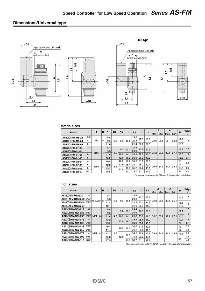
57
L4
A
L3
øD2
M1
L1
L2
øD
1
T
Applicable tube O.D. ød
Dimensions/Elbow Type
Metric sizes
d T
M5
R1/8
R1/4
H
8
12
17
D1
8.4 9.311.6 9.3 9.311.615.210.412.815.218.5
D2
9.6
14.2
18.5
L1
17.317.318.120.420.420.425.325.225.227.233.9
L2
22.122.122.927.527.527.532.434.434.436.443.2
Max.
25
32.1
34.4
M1
12.7
13.5
12.7
13.518.516 17 18.521.0
Weightg
7
17
19
32
3436
∗ Reference dimensions for M5 and R threads after installation.
Min.
22.2
27.1
29.4
A ∗L4
M5 typeU10/32 type
Model
AS12 1FM-M5-23 AS12 1FM-M5-04 AS12 1FM-M5-06 AS22 1FM-01-23 AS22 1FM-01-04 AS22 1FM-01-06 AS22 1FM-01-08 AS22 1FM-02-04 AS22 1FM-02-06 AS22 1FM-02-08 AS22 1FM-02-10
Inch sizes
d
1/8"5/32"3/16"1/4"1/8"5/32"3/16"1/4"5/16"5/32"3/16"1/4"5/16"3/8"
T
10-32UNF
NPT1/8
NPT1/4
H
8
12.7
17.5
D1
8.4 9.311.412
9.3
11.413.215.210.411.413.215.217.9
D2
9.6
14.2
18.5
L1
17.3
21.318.3
20.4
23.123.925.325.224.925.227.233.9
L2
22.1
26.123.1
27.5
30.231 32.434.434.234.536.443.2
Max.
30.1
32.1
34.4
M1
12.7
16.513.5
12.7
16.518.521 16 17 18.5
21
Weightg
7
16
17
1921
32
34
36
∗ Reference dimensions for 10-32UNF and NPT threads after installation.
Min.
25.1
27.1
29.4
A ∗ L4Model
øD
1
Applicable tube O.D. ød
M1
L1
L2
T
H
L4
øD2
L3
A
AS12 1FM-U10/32-01AS12 1FM-U10/32-03AS12 1FM-U10/32-05AS12 1FM-U10/32-07AS22 1FM-N01-01AS22 1FM-N01-03AS22 1FM-N01-05AS22 1FM-N01-07AS22 1FM-N01-09AS22 1FM-N02-03AS22 1FM-N02-05AS22 1FM-N02-07AS22 1FM-N02-09AS22 1FM-N02-11
3.24 6 3.24 6 8 4 6 8
10
(width across flats)H
(width across flats)
L3
12.3
11.7
13.4
17.7
19.5
Max.
28.6
35.2
39.9
Min.
25.8
30.2
34.9
L3
12.3
11.7
13.4
13.4
17.7
19.5
Max.
33.8
35.2
39.9
Min.
28.8
30.2
34.9
Dimensions/Universal type
Metric sizes
Model
AS13 1FM-M5-23 AS13 1FM-M5-04 AS13 1FM-M5-06 AS23 1FM-01-23 AS23 1FM-01-04 AS23 1FM-01-06 AS23 1FM-01-08 AS23 1FM-02-04 AS23 1FM-02-06 AS23 1FM-02-08 AS23 1FM-02-10
d T
M5
R1/8
R1/4
H
8
14.2
18.5
D1
8.4 9.311.6 8.4 9.311.615.210.412.815.218.5
D2
9.6
14.2
18.5
D3
9.3
9.3
10.912.910.912.9
12.9
L1
10.8
13.1
14 16.216.218.418.320.2
L2
19.820.321.424.424.926.930.930.634 35.238.7
L3
17.5
20.6
17.5
22.928.221.925.228.231
L5Max.
25
32.1
34.4
Min.
22.2
27.1
29.4
A ∗ M1
12.7
13.5
12.7
13.518.516 17 18.521
Weightg
8
17
1821
33
3640
∗ Reference dimensions for M5 and R threads after installation.
M5 type
L5A L
4
M1
L3
øD2L1L2
øD
3
øD1Applicable tube O.D. ød
T øD2
L4
M1
L3
HApplicable tube O.D. ød
øD1
L5A
T
L1
L2ø
D3
Inch sizes
Model
AS13 1FM-U10/32-01AS13 1FM-U10/32-03AS13 1FM-U10/32-05AS13 1FM-U10/32-07AS23 1FM-N01-01SAS23 1FM-N01-03SAS23 1FM-N01-05SAS23 1FM-N01-07SAS23 1FM-N01-09SAS23 1FM-N02-03SAS23 1FM-N02-05SAS23 1FM-N02-07SAS23 1FM-N02-09SAS23 1FM-N02-11S
d
1/8"5/32"3/16"1/4"1/8"5/32"3/16"1/4"5/16"5/32"3/16"1/4"5/16"3/8"
T
10-32UNF
NPT1/8
NPT1/4
H
8
12.7
17.5
D1
8.4 9.311.412 8.4 9.311.413.215.210.411.413.215.217.9
D2
9.6
14.2
18.5
D3
9.3
9.3
10.9
12.9
10.9
12.9
L1
10.8
13.1
14
16.2
16.2
18.3
20.2
L2
19.820.321.321.624.424.926.829.930.930.631.134.235.238.7
L3
17.5
23.320.7
17.5
23.925.628.221.923.925.628.231
L5Max.
30.1
32.1
34.4
Min.
25.1
27.1
29.4
A ∗M1
12.7
16.513.7
12.7
16.518.521 16 17 18.5
21
Weightg
7
8
17
18
19213233363940
∗ Reference dimensions for 10-32UNF and NPT threads after installation.
3.24 6 3.24 6 8 4 6 8
10
H(width across flats)
(width across flats)
L4
28.7
31.8
30.9
36.3 40.8 39.6 42.1 45.1 47.9
Max.
28.6
35.2
39.9
Min.
25.8
30.2
34.9
L4
28.7
34.531.9
30.9
37.338.240.839.641.642.545.147.9
Max.
33.8
35.2
39.9
Min.
28.8
30.2
34.9
Speed Controller for Low Speed Operation Series AS-FM

58
AS
Specifications
Needle Valve/Flow Rate Characteristics
How to Order
12
2 Meter-outMeter-in
Body sizeM5 standard1/8, 1/4 standard
Type
Direct cylinderconnectionelbow type
Control system01
Metric thread (M5)Unified thread (10-32UNF)
NPT
Cylinder sideR
Tube sideRc
Thread typeSymbol
Nil
N
For low speed control
NoneWith sealant
NilS
Option
Applicable seriesAS12 0M-M5
AS12 0M-U10/32AS22 0M-01AS22 0M-02
Port sizeSymbol
M5U10/32
0102
Port sizes
Port size
Applicable cylinder bore size mm
Proof pressure
Maximum operating pressure
Minimum operating pressure
Ambient and fluid temperature
Number of needle revolutions
Option
Weight g
Controlled flow
Free flow
Cylinder side
Tube side
Model
Flow rate l /min (ANR)
Effective area mm²
Flow rate l /min (ANR)
Effective area mm²
JIS symbol
AS12 0M
6, 10, 15, 20, 25
20 revolutions
–
11.5
7
0.1
105
1.6
AS22 0M- 01
20, 25, 32, 40
1.5MPa
1.0MPa
0.1MPa
–5 to 60°C (with no freezing)
10 revolutions
With sealant
36
12
0.2
280
4.3
AS22 0M- 02
74
38
0.6
420
6.5
M5 10-32UNF NPT1/8 NPT1/4R1/8
Rc1/8
R1/4
Rc1/4
2 2 0 0 M
M510-32UNF
1/ 81/ 4
AS12 0M AS22 0M- 01 AS22 0M- 02
Flo
w r
ate
l/m
in (
AN
R)
Effe
ctiv
e ar
ea
mm
²
0.15
0.1
0.05
Number of needle revolutions10 20
10
5
0
Upstream pressure 0.5MPa
Flo
w r
ate
l/m
in (
AN
R)
Effe
ctiv
e ar
ea
mm
²
0.3
0.2
0.1
0
Number of needle revolutions
5 10
20
10
0
Upstream pressure 0.5MPa
Flo
w r
ate
l/m
in (
AN
R)
Effe
ctiv
e ar
ea
mm
²
0.8
0.6
0.4
0.2
0Number of needle revolutions
5 10
50
40
30
20
10
0
Upstream pressure 0.5MPa
0
Note 1) The flow rate value is at a pressure of 0.5MPa and temperature of 20°C.
Note 2) The meter-out and meter-in types can be visually identified by the lock nut. On the meter-out type it is electroless nickel plated, while on the meter-in type it is black zinc chromated.
Note 3) All brass parts are electroless nickel plated. The knob on all types and the lock nut on the meter-in type are black zinc chromated.
∗ M5 and U10/32 are not available with sealant.
01
Speed Controller for Low Speed Operation
Series AS-MStandard Type (Metal Body)

59
AS
Specifications
Needle Valve/Flow Rate Characteristics
How to Order
12
2 Meter-outMeter-in
Body sizeM5 standard1/8, 1/4 standard
Type
Direct cylinderconnectionelbow type
Control system01
Metric thread (M5)Unified thread (10-32UNF)
NPT
Cylinder sideR
Tube sideRc
Thread typeSymbol
Nil
N
For low speed control
NoneWith sealant
NilS
Option
Applicable seriesAS12 0M-M5
AS12 0M-U10/32AS22 0M-01AS22 0M-02
Port sizeSymbol
M5U10/32
0102
Port sizes
Port size
Applicable cylinder bore size mm
Proof pressure
Maximum operating pressure
Minimum operating pressure
Ambient and fluid temperature
Number of needle revolutions
Option
Weight g
Controlled flow
Free flow
Cylinder side
Tube side
Model
Flow rate l /min (ANR)
Effective area mm²
Flow rate l /min (ANR)
Effective area mm²
JIS symbol
AS12 0M
6, 10, 15, 20, 25
20 revolutions
–
11.5
7
0.1
105
1.6
AS22 0M- 01
20, 25, 32, 40
1.5MPa
1.0MPa
0.1MPa
–5 to 60°C (with no freezing)
10 revolutions
With sealant
36
12
0.2
280
4.3
AS22 0M- 02
74
38
0.6
420
6.5
M5 10-32UNF NPT1/8 NPT1/4R1/8
Rc1/8
R1/4
Rc1/4
2 2 0 0 M
M510-32UNF
1/ 81/ 4
AS12 0M AS22 0M- 01 AS22 0M- 02
Flo
w r
ate
l/m
in (
AN
R)
Effe
ctiv
e ar
ea
mm
²
0.15
0.1
0.05
Number of needle revolutions10 20
10
5
0
Upstream pressure 0.5MPa
Flo
w r
ate
l/m
in (
AN
R)
Effe
ctiv
e ar
ea
mm
²
0.3
0.2
0.1
0
Number of needle revolutions
5 10
20
10
0
Upstream pressure 0.5MPa
Flo
w r
ate
l/m
in (
AN
R)
Effe
ctiv
e ar
ea
mm
²
0.8
0.6
0.4
0.2
0Number of needle revolutions
5 10
50
40
30
20
10
0
Upstream pressure 0.5MPa
0
Note 1) The flow rate value is at a pressure of 0.5MPa and temperature of 20°C.
Note 2) The meter-out and meter-in types can be visually identified by the lock nut. On the meter-out type it is electroless nickel plated, while on the meter-in type it is black zinc chromated.
Note 3) All brass parts are electroless nickel plated. The knob on all types and the lock nut on the meter-in type are black zinc chromated.
∗ M5 and U10/32 are not available with sealant.
01
Construction
Dimension
Meter-out type Meter-in type
Parts listNo.
1234567891011121314
Description Material
Zinc alloy
Brass
Brass
Brass
Brass
Brass
Brass Note 1)
NBR
PBT
NBR
NBR
NBR
NBR
NBR/Stainless
Note
Black zinc chromated
Electroless nickel plated
Electroless nickel plated
Electroless nickel plated
Electroless nickel plated
Electroless nickel plated Note 2)
Note 1) The AS22�0M type is steel.Note 2) The meter-in type is black zinc chromated.
AS1200M AS2200M AS1210M AS2210M
Body A
Handle
Body B
Needle
Needle guide
Seat ring
Lock nut
U-seal
Bushing
O-ring
O-ring
O-ring
O-ring
Gasket
24.8
(M
ax. 2
9.8)
8
28.2
(M
ax. 3
3.2)
ø9
10.3
10
M5 x 0.8
M5 x 0.810-32UNF
AS12 0M
Dimensions
T1 T2 H L1
10
18
27.2
L2D2
9
14.6
19.5
D1
9
14.3
18
Max.
29.8
32.4
34.9
∗ Dimensions for R and NPT threads after installation
Min.
24.8
27.4
29.9
A ∗
AS22 0M- 0102
L2 A
L3
øD2
L1
øD
1
T1
T2
Model
AS12 0M-M5
AS12 0M-U10/32
AS22 0M-01
AS22 0M-N01
AS22 0M-02
AS22 0M-N02
M5
10-32UNF
NPT1/8
NPT1/4
R1/8
R1/4
Rc1/8
Rc1/4
�9
8
12
12.7
17
17.5
H(width across flats)
Max.
33.2
35.5
39.4
Min.
28.2
30.5
35.4
L3
10.3
13.2
17.5
Speed Controller for Low Speed Operation Series AS-FM

60
Specifications
Flow Rate and Effective Area
Applicable cylinder bore size
(mm)3.2
1/8"
5/32"
3/16"
1/4"
5/16"
Applicable tubing O.D.
8
6
4
Proof pressure
Maximum operating pressure
Minimum operating pressure
Ambient and fluid temperature
Number of needle revolutions
Applicable tubing materials Note 2)
1.5MPa
1MPa
0.1MPa
0 to 60°C
10 revolutions (20 revolutions Note 1) )
Nylon, Soft nylon, Polyurethane, Soft polyurethane
Flow rate l/min (ANR)
Effective area mm²
Flow rate l/min (ANR)
Effective area mm²
ø1/8", ø5/32", ø3/16"ø1/4"
Tube O.D.
Controlledflow
Free flow
ø4
ø5/32"
130
2
ø6
ø3/16", ø1/4"
230
3.5
ø6
ø3/16"
290
4.5
ø8
ø1/4", ø5/16"
460
7
Note) The flow rate value is at a pressure of 0.5MPa and temperature of 20°C.
Model
Model AS1001FM
ø3.2, ø4, ø6
7
0.1
100
1.5
AS2001FM
12
0.2
AS2051FM
38
0.6
AS1001FM
AS2001FM
AS2051FM
6, 10, 16, 20
20, 25, 32
20, 25, 32, 40
Metric size Inch size
Metric size
Inch size
Models
Flow direction symbols on body
Sym
bol
JIS
sym
bol
Note 1) For type AS1001FM.Note 2) Use caution regarding the maximum operating pressure with soft nylon, polyurethane and soft polyurethane.
(Refer to CAT.E501-B "Air Fittings and Tubing" for details.)Note 3) All brass parts are electroless nickel plated.
The knob of the M5 type is black zinc chromated.
Speed Controller for Low Speed Operation
Series AS-FMIn-line Type

61
Specifications
Flow Rate and Effective Area
Applicable cylinder bore size
(mm)3.2
1/8"
5/32"
3/16"
1/4"
5/16"
Applicable tubing O.D.
8
6
4
Proof pressure
Maximum operating pressure
Minimum operating pressure
Ambient and fluid temperature
Number of needle revolutions
Applicable tubing materials Note 2)
1.5MPa
1MPa
0.1MPa
0 to 60°C
10 revolutions (20 revolutions Note 1) )
Nylon, Soft nylon, Polyurethane, Soft polyurethane
Flow rate l/min (ANR)
Effective area mm²
Flow rate l/min (ANR)
Effective area mm²
ø1/8", ø5/32", ø3/16"ø1/4"
Tube O.D.
Controlledflow
Free flow
ø4
ø5/32"
130
2
ø6
ø3/16", ø1/4"
230
3.5
ø6
ø3/16"
290
4.5
ø8
ø1/4", ø5/16"
460
7
Note) The flow rate value is at a pressure of 0.5MPa and temperature of 20°C.
Model
Model AS1001FM
ø3.2, ø4, ø6
7
0.1
100
1.5
AS2001FM
12
0.2
AS2051FM
38
0.6
AS1001FM
AS2001FM
AS2051FM
6, 10, 16, 20
20, 25, 32
20, 25, 32, 40
Metric size Inch size
Metric size
Inch size
Models
Flow direction symbols on body
Sym
bol
JIS
sym
bol
Note 1) For type AS1001FM.Note 2) Use caution regarding the maximum operating pressure with soft nylon, polyurethane and soft polyurethane.
(Refer to CAT.E501-B "Air Fittings and Tubing" for details.)Note 3) All brass parts are electroless nickel plated.
The knob of the M5 type is black zinc chromated.
AS
Needle Valve/Flow Rate Characteristics
How to Order
100200205
Body sizeM5 standard1/8 standard1/4 standard
23040608
Applicable tube outside diameterMetric size
ø3.2 ∗
ø4ø6ø8
0103050709
ø1/8"ø5/32"ø3/16"ø1/4"ø5/16"
For low speed control
With One-touch fitting
200 1 F M 06
Inch size
∗Use a ø1/8" tube.
AS1001FM AS2001FM AS2051FM
Flo
w r
ate
l/m
in (
AN
R)
Effe
ctiv
e ar
ea
mm
²
0.15
0.1
0.05
Number of needle revolutions10 20
10
5
0
Upstream pressure 0.5MPa
Flo
w r
ate
l/m
in (
AN
R)
Effe
ctiv
e ar
ea
mm
²
0.3
0.2
0.1
0Number of needle revolutions
5 10
20
10
0
Upstream pressure 0.5MPa F
low
rat
e l
/min
(A
NR
)
Effe
ctiv
e ar
ea
mm
²
0.8
0.6
0.4
0.2
0
Number of needle revolutions
5 10
50
40
30
20
10
0
Upstream pressure 0.5MPa
0
Speed Controller for Low Speed Operation Series AS-FM

62
Metric sizes
d
3.2464668
D1
8.4 9.311.6 9.311.612.815.2
D2
10
11.8
14.8
L1
38 39.240.740.744.853.259.8
L2
4.55.26.25.26.36.78.1
Max.27.728.529.832.633.735.236.5
M1
12.7
13.712.713.71718
Weightg
678
12132631
Min.24.925.526.627.628.730.231.5
L3Model
Inch sizes
d
1/8"5/32"3/16"1/4"
5/32"3/16"1/4"
3/16"1/4"
5/16"
D1
8.4 9.311.412 9.311.413.211.413.215.2
D2
10
11.8
14.8
L1
38 39.248.740.740.750 52.252.254.459.8
L2
4.55.2
6.2
5.26.27.16.27.18.1
Max.27.728.5
27.7
32.633.634.534.635.536.5
M1
12.7
16.513.712.716.517 16.517 18
Weightg
6789121821242631
Min.24.925.5
24.7
29.628.629.529.630.531.5
L3Model
AS1001FM-01AS1001FM-03AS1001FM-05AS1001FM-07AS2001FM-03AS2001FM-05AS2001FM-07AS2051FM-05AS2051FM-07AS2051FM-09
Construction
Dimensions
Parts listNo.
123456789
1011
Description Material
PBT
PBT Note 1)
Brass
Brass
Brass
Brass Note 2)
NBR
POM Note 3)
POM, Stainless Note 4)
NBR
NBR
Note
Black
Electroless nickel plated
Electroless nickel plated
Electroless nickel plated
Electroless nickel plated
Note 1) The AS1001FM type is black zinc chromated brass.Note 2) The AS20 1FM type is steel.Note 3) ø3/16" is brass (electroless nickel plated).Note 4) ø3/16" is POM, stainless steel and brass (electroless nickel plated).
Body A
Handle
Body B
Needle
Needle guide
Lock nut
U-seal
Spacer
Cassette
Seal
O-ring
AS1001FM-23AS1001FM-04AS1001FM-06AS2001FM-04AS2001FM-06AS2051FM-06AS2051FM-08
Series AS-FM

63
Metric sizes
d
3.2464668
D1
8.4 9.311.6 9.311.612.815.2
D2
10
11.8
14.8
L1
38 39.240.740.744.853.259.8
L2
4.55.26.25.26.36.78.1
Max.27.728.529.832.633.735.236.5
M1
12.7
13.712.713.71718
Weightg
678
12132631
Min.24.925.526.627.628.730.231.5
L3Model
Inch sizes
d
1/8"5/32"3/16"1/4"
5/32"3/16"1/4"
3/16"1/4"
5/16"
D1
8.4 9.311.412 9.311.413.211.413.215.2
D2
10
11.8
14.8
L1
38 39.248.740.740.750 52.252.254.459.8
L2
4.55.2
6.2
5.26.27.16.27.18.1
Max.27.728.5
27.7
32.633.634.534.635.536.5
M1
12.7
16.513.712.716.517 16.517 18
Weightg
6789121821242631
Min.24.925.5
24.7
29.628.629.529.630.531.5
L3Model
AS1001FM-01AS1001FM-03AS1001FM-05AS1001FM-07AS2001FM-03AS2001FM-05AS2001FM-07AS2051FM-05AS2051FM-07AS2051FM-09
Construction
Dimensions
Parts listNo.
123456789
1011
Description Material
PBT
PBT Note 1)
Brass
Brass
Brass
Brass Note 2)
NBR
POM Note 3)
POM, Stainless Note 4)
NBR
NBR
Note
Black
Electroless nickel plated
Electroless nickel plated
Electroless nickel plated
Electroless nickel plated
Note 1) The AS1001FM type is black zinc chromated brass.Note 2) The AS20 1FM type is steel.Note 3) ø3/16" is brass (electroless nickel plated).Note 4) ø3/16" is POM, stainless steel and brass (electroless nickel plated).
Body A
Handle
Body B
Needle
Needle guide
Lock nut
U-seal
Spacer
Cassette
Seal
O-ring
AS1001FM-23AS1001FM-04AS1001FM-06AS2001FM-04AS2001FM-06AS2051FM-06AS2051FM-08
Models
Specifications
Flow Rate and Effective Area
ASD230FM-M5ASD330FM-01ASD430FM-02ASD230FM-U10/32ASD330FM-N01ASD430FM-N02
Model
Applicable tubingMetric size Inch size
4
6
8
10
1/8"
5/32"
3/16"
1/4"
5/16"
3/8"
Proof pressure
Maximum operating pressure
Minimum operating pressure
Ambient and fluid temperature
Number of needle revolutions
Applicable tubing materials Note 2)
1.5MPa
1MPa
0.1MPa
0 to 60°C10 revolutions (20 revolutions Note 1))
Nylon, Soft nylon, Polyurethane, Soft polyurethane
Note) The flow rate value is at a pressure of 0.5MPa and temperature of 20°C.
Model
Tube O.D.
Controlledflow
Free flow
Metric size
Inch size
Flow rate l /min (ANR)
Effective area mm²
Flow rate l /min (ANR)
Effective area mm²
ASD230FM ASD330FM ASD430FM
ø4, ø6
7
0.1
1.1
75
ø6, ø8
12 38
0.60.2
175 350
5.32.7
ø8, ø10ø6
295
4.5
ø1/8", ø5/32"ø3/16", ø1/4"
ø1/4", ø5/16"ø3/8"
ø3/16", ø1/4" –
JIS symbol
Flow direction symbols on body
Meter-out type Meter-in type
Sym
bol
JIS
sym
bol
Two flow control valves and check valves integrated.Prevention of lurching and speed control for single acting cylinders.Stable speed control possible even with fluctuating loads.Low speed control for small bore cylinders.
Note 1) For type ASD230FM.
Note 2) Use caution regarding the maximum operating pressure with soft nylon, polyurethane and soft polyurethane.(Refer to Page 7-146 and 7-147 "Air Fittings and Tubing" for details.)Note 3) All brass parts are electroless nickel plated.The meter-in side lock nut and the M5 type knob are black zinc chromated.
Dual Speed Controller for Low Speed Operation
Series ASD-FM

64
How to Order
ASD
234
M5 standard1/8 standard1/4 standard
Body size
Model
With One-touch fitting
Thread type
3 Universal
NilMetric thread (M5)
Unified thread (10-32UNF)R
NPT
Port size
With sealant∗ "S" is not applicable to M5 and U10/32 types, as they are not available with sealant.
M5U10/32
0102
M510-32UNF
1/81/4
Applicable tube outside diameterMetric size Inch size
04060810
ø4ø6ø8ø10
010305070911
ø1/8"ø5/32"ø3/16"ø1/4"ø5/16"ø3/8"
Needle Valve/Flow Rate Characteristics
33 0 F
For low speed control
M 01 06 S
N
ASD230FM ASD330FM ASD430FM
Flo
w r
ate
l/m
in (
AN
R)
Effe
ctiv
e ar
ea
mm
2
0.15
0.1
0.05
Number of needle revolutions10 20
10
5
0
Upstream pressure 0.5MPa
Flo
w r
ate
l/m
in (
AN
R)
Effe
ctiv
e ar
ea
mm
²
0.3
0.2
0.1
0Number of needle revolutions
5 10
20
10
0
Upstream pressure 0.5MPa
Flo
w r
ate
l/m
in (
AN
R)
Effe
ctiv
e ar
ea
mm
²
0.8
0.6
0.4
0.2
0Number of needle revolutions
5 10
50
40
30
20
10
0
Upstream pressure 0.5MPa
0
Series ASD-FM

65
How to Order
ASD
234
M5 standard1/8 standard1/4 standard
Body size
Model
With One-touch fitting
Thread type
3 Universal
NilMetric thread (M5)
Unified thread (10-32UNF)R
NPT
Port size
With sealant∗ "S" is not applicable to M5 and U10/32 types, as they are not available with sealant.
M5U10/32
0102
M510-32UNF
1/81/4
Applicable tube outside diameterMetric size Inch size
04060810
ø4ø6ø8ø10
010305070911
ø1/8"ø5/32"ø3/16"ø1/4"ø5/16"ø3/8"
Needle Valve/Flow Rate Characteristics
33 0 F
For low speed control
M 01 06 S
N
ASD230FM ASD330FM ASD430FM
Flo
w r
ate
l/m
in (
AN
R)
Effe
ctiv
e ar
ea
mm
2
0.15
0.1
0.05
Number of needle revolutions10 20
10
5
0
Upstream pressure 0.5MPa
Flo
w r
ate
l/m
in (
AN
R)
Effe
ctiv
e ar
ea
mm
²
0.3
0.2
0.1
0Number of needle revolutions
5 10
20
10
0
Upstream pressure 0.5MPa
Flo
w r
ate
l/m
in (
AN
R)
Effe
ctiv
e ar
ea
mm
²
0.8
0.6
0.4
0.2
0Number of needle revolutions
5 10
50
40
30
20
10
0
Upstream pressure 0.5MPa
0
Construction
Parts listNo.
Body A
Elbow body
Handle
Body B
Body B
Needle
Seat ring
Needle guide
Lock nut
Lock nut
Material
PBT
PBT
PBT Note 1)
Brass
Brass
Brass
Brass
Brass
Brass Note 2)
Brass Note 2)
Note
Black
Electroless nickel plated
Electroless nickel plated
Electroless nickel plated
Electroless nickel plated
Electroless nickel plated
Electroless nickel plated
Black zinc chromated
Description No.
1112131415161718192021
Material
NBR
NBR
POM, Stainless Note 3)
NBR
NBR
NBR
NBR
NBR
NBR
NBR, Stainless
POM Note 4)
NoteDescription
U-seal
U-seal
Cassette
Seal
O-ring
O-ring
O-ring
O-ring
O-ring
Gasket
Spacer
M5 type only
ASD230FM ASD330FM, 430FM
Parts list
123456789
10
Note 1) AS1001FM type is black zinc chromated brass.Note 2) The AS201FM type is steel.Note 3) ø3/16" and ø3/8 are POM, stainless, and brass (electroless nickel plated).Note 4) ø3/16" and ø3/8 are brass (electroless nickel plated).
Dual Speed Controller for Low Speed Operation Series ASD-FM

66
Dimensions/Metric Sizes
7.8
10.6
11
d T H D1 D2 D3 L1 L2 L3Model
ASD230FM-M5-04
ASD230FM-M5-06
ASD330FM-01-06S
ASD330FM-01-08S
ASD430FM-02-06S
ASD430FM-02-08S
ASD430FM-02-10S
M5
R1/8
R1/4
8
12
17
4
6
6
8
6
8
10
9.3
11.6
11.6
15.2
12.8
15.2
18.5
9.6
14.2
18.5
10
11.8
15
11.7
14
15.8
18
19.7
29.4
32.5
38.5
44.8
43.5
46.5
49.3
17.5
20.6
22.9
28.2
25.2
28.2
31
34.6
39.6
38.9
41.8
29.6
34.6
33.9
36.8
30.1
32.1
34.4
25.1
27.1
29.4
12.9
13.7
13.7
18.5
17
18.5
21
L4 L5 A1 ∗A2 ∗ M1
Max. Min. Max. Max.Min. Min.
Weightg
Applicable tube O.D. ød
L2L3
M1
L4
L1
øD2
ASD230FM
Metric sizes
12
13
29
31
53
55
58
Applicable tube O.D. ød
L2L3
M1
L1
L4
øD2
ASD330FM, 430FM
∗ Reference dimensions for M5 and R threads after installation
L5 A1
A2
øD
3
øD
1
TT
L5 A1
A2
øD
3
øD
1
H(width across flats)
H(width across flats)
33.8
35.2
39.9
28.8
30.2
34.9
Series ASD-FM

67
Dimensions/Metric Sizes
7.8
10.6
11
d T H D1 D2 D3 L1 L2 L3Model
ASD230FM-M5-04
ASD230FM-M5-06
ASD330FM-01-06S
ASD330FM-01-08S
ASD430FM-02-06S
ASD430FM-02-08S
ASD430FM-02-10S
M5
R1/8
R1/4
8
12
17
4
6
6
8
6
8
10
9.3
11.6
11.6
15.2
12.8
15.2
18.5
9.6
14.2
18.5
10
11.8
15
11.7
14
15.8
18
19.7
29.4
32.5
38.5
44.8
43.5
46.5
49.3
17.5
20.6
22.9
28.2
25.2
28.2
31
34.6
39.6
38.9
41.8
29.6
34.6
33.9
36.8
30.1
32.1
34.4
25.1
27.1
29.4
12.9
13.7
13.7
18.5
17
18.5
21
L4 L5 A1 ∗A2 ∗ M1
Max. Min. Max. Max.Min. Min.
Weightg
Applicable tube O.D. ød
L2L3
M1
L4
L1
øD2
ASD230FM
Metric sizes
12
13
29
31
53
55
58
Applicable tube O.D. ød
L2L3
M1
L1
L4
øD2
ASD330FM, 430FM
∗ Reference dimensions for M5 and R threads after installation
L5 A1
A2
øD
3
øD
1
TT
L5 A1
A2
øD
3
øD
1
H(width across flats)
H(width across flats)
33.8
35.2
39.9
28.8
30.2
34.9
10-32UNF
NPT1/8
NPT1/4
7.8
10.6
11
d T H D1 D2 D3 L1 L2 L3Model
ASD230FM-U10/32-01
ASD230FM-U10/32-03
ASD230FM-U10/32-05
ASD230FM-U10/32-07
ASD330FM-N01-05S
ASD330FM-N01-07S
ASD330FM-N01-09S
ASD430FM-N02-07S
ASD430FM-N02-09S
ASD430FM-N02-11S
8
12.7
17.5
1/8"
5/32"
3/16"
1/4"
3/16"
1/4"
5/16"
1/4"
5/16"
3/8"
8.4
9.3
11.4
12
11.4
13.2
15.2
13.2
15.2
18.5
9.6
14.2
18.5
10
11.8
15
11.7
14
15.8
18
19.7
29.4
35.2
32.6
39.5
42.2
44.8
43.9
46.5
49.3
17.5
23.3
20.7
23.9
25.6
28.2
25.6
28.2
32.6
34.6
39.6
38.9
41.7
29.6
34.6
33.9
36.7
30.1
32
34.6
25.1
27
29.6
12.9
16.5
13.5
16.5
17
18.5
17
18.5
21
L4 L5 A1 ∗A2 ∗ M1
Max. Min. Max. Max.Min. Min.
Weightg
∗ Reference dimensions for 10-32UNF and NPT threads after installation
Inch sizes
Applicable tube O.D. ød
L2L3
M1
L4
L1
øD2
ASD230FM
Applicable tube O.D. ød
L2L3
M1
L1
L4
øD2
ASD330FM, 430FM
12
13
14
15
30
31
55
62
Dimensions/Inch SizesL
5 A1
A2
øD
3
øD
1
TT
L5 A1
A2
øD
3
øD
1
H(width across flats)
H(width across flats
33.8
35.2
39.9
28.8
30.2
34.9
Dual Speed Controller for Low Speed Operation Series ASD-FM

68
Model
Specifications
Speed Controllerwith Pilot Check Valve
Series ASP
Flow Rate and Effective Sectional Area
ASP330F-01ASP430F-02ASP530F-03ASP630F-04ASP430F-F02ASP530F-F03ASP630F-F04ASP330F-N01ASP430F-N02ASP530F-N03ASP630F-N04
R(PT)1/8
R(PT)1/4
R(PT)3/8
R(PT)1/2
R(PT)1/4
R(PT)3/8
R(PT)1/2
NPT1/8
NPT1/4
NPT3/8
NPT1/2
Part No. Port size
Applicable tube outside diameter
Millimeter size Inch size
ø6
••
•
ø8
•••
••
ø10
••
••
ø12
•
•
ø1/4"
••
ø5/16"
•••
ø3/8"
••
Proof pressure
Maximum operating pressure
Minimum operating pressure
Pilot check valve actuation pressure
Ambient & fluid temperature
Number of needle revolutions
Applicable tube material
1.5MPa{15.3kgf/cm2}
1MPa{10.2kgf/cm2}
0.1MPa{1kgf/cm2}
50% or more of operating pressure
-5 to 60°C (Without freezing)
10 revolutions
Nylon, Soft nylon, Polyurethane
Note) Use caution with soft nylon or polyurethane at maximum operating pressures. For details, refer to Page 7-146 and 7-147 "Air Fittings & Tubing" for pneumatic piping
Model
Tube outside
diameter
Controlled flow(Free flow)
Millimeter size
Inch size
Flow rate l /min(ANR){N l /min}
Effective sectionalarea mm2
ASP330F ASP430F ASP530F ASP630F
180
2.9
ø6, ø8
330
5.2
ø6
—ø1/4"
ø5/16"
350
5.4
ø10 ø12
ø5/16" —
600 750 1100 1190
9.3 11.6 17 18.4
360° freedom for tubemounting direction
ø1/2"
•Note) All brass parts are electroless nickel plated.
ø8 ø8 ø10
ø1/4"
ø5/16"ø3/8"
ø3/8"
ø1/2"
Note) The indicated flow rate values are at a pressure of 0.5MPa and a temperature of 20°C.
JIS Symbol
Pilot port
M5
Rc(PT)1/8
Rc(PT)1/8
Rc(PT)1/4
G(PF)1/8
G(PF)1/8
G(PF)1/4
10-32UNF
NPT1/8
NPT1/8
NPT1/4
Standard electroless nickelplating specification
How to Order
ASP 3
3456
1/8 standard1/4 standard3/8 standard1/2 standard
Body size
Type
Pilot check valve
3 Universal Port size
With seals
Symbol01020304
F02F03F04N01N02N03N04
Cylinder sideR(PT)1/8R(PT)1/4R(PT)3/8R(PT)1/2R(PT)1/4R(PT)3/8R(PT)1/2NPT1/8NPT1/4NPT3/8NPT1/2
Applicable tube outside diameterMillimeter size
06081012
ø6ø8
ø10ø12
Inch size07091113
ø1/4"ø5/16"ø3/8"ø1/2"
Needle Valve/Flow Rate Characteristics
ASP330F ASP430F
ASP530F ASP630F
200
05 10
3
2
1
0
Needle revolutions (Revolutions)
Flo
w r
ate
l/m
in (
AN
R)
Effe
ctiv
e se
ctio
nal a
rea
mm
2
100
400
05 10
6
4
2
0
Needle revolutions (Revolutions)
Flo
w r
ate
l/m
in (
AN
R)
Effe
ctiv
e se
ctio
nal a
rea
mm
2
100
200
3000607, 08, 09
1500
05 10
20
15
10
0
Flo
w r
ate
l/m
in (
AN
R)
Effe
ctiv
e se
ctio
nal a
rea
mm
2
500
1011, 12, 13
1000
5
Needle revolutions (Revolutions)
05 10
14
10
8
0
Flo
w r
ate
l/m
in (
AN
R)
Effe
ctiv
e se
ctio
nal a
rea
mm
2
500
1000
2
Needle revolutions (Revolutions)
12
6
4
10, 1108, 09
30F 01 06 S
With One-touch fittings
Pilot portM5
Rc(PT)1/8Rc(PT)1/8Rc(PT)1/4G(PF)1/8G(PF)1/8G(PF)1/410-32UNF
NPT1/8NPT1/8NPT1/4

69
Model
Specifications
Speed Controllerwith Pilot Check Valve
Series ASP
Flow Rate and Effective Sectional Area
ASP330F-01ASP430F-02ASP530F-03ASP630F-04ASP430F-F02ASP530F-F03ASP630F-F04ASP330F-N01ASP430F-N02ASP530F-N03ASP630F-N04
R(PT)1/8
R(PT)1/4
R(PT)3/8
R(PT)1/2
R(PT)1/4
R(PT)3/8
R(PT)1/2
NPT1/8
NPT1/4
NPT3/8
NPT1/2
Part No. Port size
Applicable tube outside diameter
Millimeter size Inch size
ø6
••
•
ø8
•••
••
ø10
••
••
ø12
•
•
ø1/4"
••
ø5/16"
•••
ø3/8"
••
Proof pressure
Maximum operating pressure
Minimum operating pressure
Pilot check valve actuation pressure
Ambient & fluid temperature
Number of needle revolutions
Applicable tube material
1.5MPa{15.3kgf/cm2}
1MPa{10.2kgf/cm2}
0.1MPa{1kgf/cm2}
50% or more of operating pressure
-5 to 60°C (Without freezing)
10 revolutions
Nylon, Soft nylon, Polyurethane
Note) Use caution with soft nylon or polyurethane at maximum operating pressures. For details, refer to Page 7-146 and 7-147 "Air Fittings & Tubing" for pneumatic piping
Model
Tube outside
diameter
Controlled flow(Free flow)
Millimeter size
Inch size
Flow rate l /min(ANR){N l /min}
Effective sectionalarea mm2
ASP330F ASP430F ASP530F ASP630F
180
2.9
ø6, ø8
330
5.2
ø6
—ø1/4"
ø5/16"
350
5.4
ø10 ø12
ø5/16" —
600 750 1100 1190
9.3 11.6 17 18.4
360° freedom for tubemounting direction
ø1/2"
•Note) All brass parts are electroless nickel plated.
ø8 ø8 ø10
ø1/4"
ø5/16"ø3/8"
ø3/8"
ø1/2"
Note) The indicated flow rate values are at a pressure of 0.5MPa and a temperature of 20°C.
JIS Symbol
Pilot port
M5
Rc(PT)1/8
Rc(PT)1/8
Rc(PT)1/4
G(PF)1/8
G(PF)1/8
G(PF)1/4
10-32UNF
NPT1/8
NPT1/8
NPT1/4
Standard electroless nickelplating specification
How to Order
ASP 3
3456
1/8 standard1/4 standard3/8 standard1/2 standard
Body size
Type
Pilot check valve
3 Universal Port size
With seals
Symbol01020304
F02F03F04N01N02N03N04
Cylinder sideR(PT)1/8R(PT)1/4R(PT)3/8R(PT)1/2R(PT)1/4R(PT)3/8R(PT)1/2NPT1/8NPT1/4NPT3/8NPT1/2
Applicable tube outside diameterMillimeter size
06081012
ø6ø8
ø10ø12
Inch size07091113
ø1/4"ø5/16"ø3/8"ø1/2"
Needle Valve/Flow Rate Characteristics
ASP330F ASP430F
ASP530F ASP630F
200
05 10
3
2
1
0
Needle revolutions (Revolutions)
Flo
w r
ate
l/m
in (
AN
R)
Effe
ctiv
e se
ctio
nal a
rea
mm
2
100
400
05 10
6
4
2
0
Needle revolutions (Revolutions)
Flo
w r
ate
l/m
in (
AN
R)
Effe
ctiv
e se
ctio
nal a
rea
mm
2
100
200
3000607, 08, 09
1500
05 10
20
15
10
0
Flo
w r
ate
l/m
in (
AN
R)
Effe
ctiv
e se
ctio
nal a
rea
mm
2
500
1011, 12, 13
1000
5
Needle revolutions (Revolutions)
05 10
14
10
8
0
Flo
w r
ate
l/m
in (
AN
R)
Effe
ctiv
e se
ctio
nal a
rea
mm
2
500
1000
2
Needle revolutions (Revolutions)
12
6
4
10, 1108, 09
30F 01 06 S
With One-touch fittings
Pilot portM5
Rc(PT)1/8Rc(PT)1/8Rc(PT)1/4G(PF)1/8G(PF)1/8G(PF)1/410-32UNF
NPT1/8NPT1/8NPT1/4
Speed Controller with pilot Check Valve Series ASP

70
Dimensions
d T1 D1
1/8
1/4
3/8
1/2
68688
101012
11.615.212.815.215.218.518.520.9
Applicable tube outside dia. ødL2
L3M
L1
H1
L5 *A
1*A
2
øD
3
øD
1øD2
Millimeter size
T2
M5
Rc(PT)1/8
Rc(PT)1/8
Rc(PT)1/4
H1
12
17
19
24
H2
8
12
12
17
D2
14.2
18.5
23
28.6
D3
41.7
46.9
64.8
L4
MAX. MIN.Model
ASP330F-01-06SASP330F-01-08SASP430F-02-06SASP430F-02-08SASP530F-03-08SASP530F-03-10SASP630F-04-10SASP630F-04-12S
L1
14 15.818 19.720.323.1
25.9
L2
38.444.743.446.451.354.164.266
L3
22.928.225.228.228.232.632.634.4
39.638.9
36.7
41.9
57.3
34.633.9
11.8
15
19.8
26.5
L5
39.5
48.7
56.2
70.3
*A1
35.2
42.4
50
61.8
*A2
10.5
10.9
14.4
18.3
M
13.718.716.818.718.720.820.821.8
Weightg
32356568
107110212215
T2
T1
H2
d T1 D1
NPT1/8
NPT1/4
NPT3/8
NPT1/2
1/4"5/16"1/4"
5/16"5/16"3/8"3/8"1/2"
13.215.213.215.215.218.518.521.7
Inch size
T2
10-32UNF
NPT1/8
NPT1/8
NPT1/4
H1
1/2"
11/16"
19
15/16"
H2
8
1/2"
1/2"
11/16"
D2
14.2
18.5
23
28.6
D3
41.7
46.9
64.8
L4
MAX. MIN.Model
ASP330F-N01-07SASP330F-N01-09SASP430F-N02-07SASP430F-N02-09SASP530F-N03-09SASP530F-N03-11SASP630F-N04-11SASP630F-N04-13S
L1
20.323.125.926.5
L2
42.244.743.946.451.354.164.266.3
L3
25.628.225.628.228.232.632.634.7
38.9
36.7
41.9
57.3
33.911.8
15
19.8
26.5
L5
39.5
48.7
56.2
70.3
*A1
35.1
42.6
50.3
61.8
*A2
10.5
10.9
14.4
18.3
M
17 18.717 18.718.720.820.821.8
Weightg
107116220230
35
68
L4
Applicable tube outside dia. ødL2L3
M
L1
øD2
T2 L4
∗ Reference dimensions for R(PT) threads after installation.
∗ Reference dimensions for NPT threads after installation.
15.8
18
(Width across flats)
(Width across flats)
L5
H1
*A1
*A2
øD
3
øD
1
T1
H2
(Width across flats)
(Width across flats)
Series ASP
Construction
Parts list
1
2
3
4
5
6
7
8
9
bk
bl
bm
bn
Body AElbow bodyKnobPilot bodyBody BNeedleNeedle guideGuideLock nutPistonValveCoverU seal
MaterialPBTPBTPBT
BrassBrassBrassBrassBrassBrassBrass
Stainless steel, NBR
BrassNBR
Note
Electroless nickel platedElectroless nickel platedElectroless nickel platedElectroless nickel platedElectroless nickel platedElectroless nickel platedElectroless nickel plated
Black zinc chromated
Description
bo
bp
bq
br
bs
bt
ck
cl
cm
cn
co
cp
MaterialPBTPBT
Stainless steelStainless steel
POM, Stainless steel Note 1)
NBR POM Note 2)
NBRNBRNBRNBR
Stainless steel
NoteDescriptionDY sealDY sealSpringSpringCassetteSealSpacerO-ringO-ringO-ringO-ringRing
Note 1) ø10, ø12, ø3/8", ø1/2" are POM, stainless steel and brass (electroless nickel plated).Note 2) ø1/4", ø3/8", ø1/2" are brass (elctroless nickel plated).
396
co
br bl
bk
8
bm
Parts list
2 ck bt bs
cp
cn
4
bp bq bo cm bn
1
5
7
cl
No.No.

71
Dimensions
d T1 D1
1/8
1/4
3/8
1/2
68688
101012
11.615.212.815.215.218.518.520.9
Applicable tube outside dia. ødL2
L3M
L1
H1
L5 *A
1*A
2
øD
3
øD
1
øD2
Millimeter size
T2
M5
Rc(PT)1/8
Rc(PT)1/8
Rc(PT)1/4
H1
12
17
19
24
H2
8
12
12
17
D2
14.2
18.5
23
28.6
D3
41.7
46.9
64.8
L4
MAX. MIN.Model
ASP330F-01-06SASP330F-01-08SASP430F-02-06SASP430F-02-08SASP530F-03-08SASP530F-03-10SASP630F-04-10SASP630F-04-12S
L1
14 15.818 19.720.323.1
25.9
L2
38.444.743.446.451.354.164.266
L3
22.928.225.228.228.232.632.634.4
39.638.9
36.7
41.9
57.3
34.633.9
11.8
15
19.8
26.5
L5
39.5
48.7
56.2
70.3
*A1
35.2
42.4
50
61.8
*A2
10.5
10.9
14.4
18.3
M
13.718.716.818.718.720.820.821.8
Weightg
32356568
107110212215
T2
T1
H2
d T1 D1
NPT1/8
NPT1/4
NPT3/8
NPT1/2
1/4"5/16"1/4"
5/16"5/16"3/8"3/8"1/2"
13.215.213.215.215.218.518.521.7
Inch size
T2
10-32UNF
NPT1/8
NPT1/8
NPT1/4
H1
1/2"
11/16"
19
15/16"
H2
8
1/2"
1/2"
11/16"
D2
14.2
18.5
23
28.6
D3
41.7
46.9
64.8
L4
MAX. MIN.Model
ASP330F-N01-07SASP330F-N01-09SASP430F-N02-07SASP430F-N02-09SASP530F-N03-09SASP530F-N03-11SASP630F-N04-11SASP630F-N04-13S
L1
20.323.125.926.5
L2
42.244.743.946.451.354.164.266.3
L3
25.628.225.628.228.232.632.634.7
38.9
36.7
41.9
57.3
33.911.8
15
19.8
26.5
L5
39.5
48.7
56.2
70.3
*A1
35.1
42.6
50.3
61.8
*A2
10.5
10.9
14.4
18.3
M
17 18.717 18.718.720.820.821.8
Weightg
107116220230
35
68
L4
Applicable tube outside dia. ødL2L3
M
L1
øD2
T2 L4
∗ Reference dimensions for R(PT) threads after installation.
∗ Reference dimensions for NPT threads after installation.
15.8
18
(Width across flats)
(Width across flats)
L5
H1
*A1
*A2
øD
3
øD
1
T1
H2
(Width across flats)
(Width across flats)
Construction
Parts list
1
2
3
4
5
6
7
8
9
bk
bl
bm
bn
Body AElbow bodyKnobPilot bodyBody BNeedleNeedle guideGuideLock nutPistonValveCoverU seal
MaterialPBTPBTPBT
BrassBrassBrassBrassBrassBrassBrass
Stainless steel, NBR
BrassNBR
Note
Electroless nickel platedElectroless nickel platedElectroless nickel platedElectroless nickel platedElectroless nickel platedElectroless nickel platedElectroless nickel plated
Black zinc chromated
Description
bo
bp
bq
br
bs
bt
ck
cl
cm
cn
co
cp
MaterialPBTPBT
Stainless steelStainless steel
POM, Stainless steel Note 1)
NBR POM Note 2)
NBRNBRNBRNBR
Stainless steel
NoteDescriptionDY sealDY sealSpringSpringCassetteSealSpacerO-ringO-ringO-ringO-ringRing
Note 1) ø10, ø12, ø3/8", ø1/2" are POM, stainless steel and brass (electroless nickel plated).Note 2) ø1/4", ø3/8", ø1/2" are brass (elctroless nickel plated).
396
co
br bl
bk
8
bm
Parts list
2 ck bt bs
cp
cn
4
bp bq bo cm bn
1
5
7
cl
No.No.
Speed Controller with pilot Check Valve Series ASP

72