Embed Size (px)
Citation preview

0
SPEED POST
DRAFT IN WIDE CIRCULATION
Our Ref: Date WRD 12/T-19 30 Jan 2015
TECHNICAL COMMITTEE: Hydraulic Gates and Valves, WRD 12 ----------------------------------------------------------------------------------------------------------------------------- ADDRESSED TO: 1. All Members of Hydraulic Gates and Valves Sectional Committee, WRD 12 2. All Interested Members of Water Resources Division Council 3. All others interested Dear Sir(s), As per the decision taken in the 14th meeting of the sectional committee, the following draft document is hosted on the BIS website www.bis.org.in: DOC. NO. TITLE WRD 12 (622) Recommendation for Design Criteria of Screw Hoists for Hydraulic Gates IS
11228 ( First Revision)
Kindly examine this draft and forward your views stating any difficulties which you are likely to experience in your business or profession, if this is finally adopted as a national standard and kindly provide your specific suggestion for revising the same in view of latest technology. Last Date for Comment is 28 Feb 2015 Comments, if any, may please be made in the format as annexed and mailed to the undersigned at the above address. Comments will be appreciated in electronic form at the e-mail address ‘[email protected]’. In case you have any difficulty in accessing the document at our website, please write to us for a hard copy. In case no comments are received or comments received are of editorial nature, you will kindly permit us to presume your approval for the above document as finalized. However, in case of comments of technical in nature are received then it may be finalized either in consultation with the Chairman, Sectional Committee or referred to the Sectional committee for further necessary action if so desired by the Chairman, Sectional Committee. Thanking you, Yours faithfully,
(J C Arora) Sc-F & Head (WRD)
Encl: as above.
For official use only DOC: WRD 12(622)WC
Jan 2015

1
DRAFT STANDARD FOR WIDE CIRCULATION
(Bureau of Indian Standards)
Recommendations for design of screw hoists for hydraulic gates (first revision to IS 11228)
(Not to be reproduced without the permission of BIS or used as standard)
-----------------------------------------------------------------------------------------------------------------------------------
Last date for receipt of comments is 28-02-2015
-----------------------------------------------------------------------------------------------------------------------------------
FOREWORD (Formal clauses to be added later) Controlled release of water to canals is made by the use of gates provided on head regulators, cross regulators, control gates in conduits and tunnels or in the body of a dam. For the operation of such small size low head gates, generally the screw hoists arc used. A screw hoist is quite simple in construction and consists of a cast iron or fabricated pedestal resting on a platform. A screw stem passes through the pedestal and platform and is connected to the gate by means of nuts/pins. The screw stem engages with a long threaded bronze nut which freely rotates in the pedestal, where thrust bearings are provided. As the nut rotates, the stem is lifted up or lowered down depending upon the direction of rotation of nut and the gate gets correspondingly lifted or lowered down. The source of power for the rotation of nut is a rotating crank (in case of hand operated screw hoists and electric motor in case of power driven screw hoists ), set of spur gears, bevel pinion and bevel gear. The screw hoist is used when a positive thrust is required to close the gate. The screw hoist is also used in case of low capacity manually operated hoist where it may not be necessary to provide any other electrically operated hoisting system. It is very compact and more economical as compared to other types of hoists. The use of screw hoist will be limited where gate vibrations are involved because of the fact that screw threads will get damaged under those conditions. The efficiency of the screw is also low. The screw hoist is used for gates with single or double point consideration. In the formulation of this standard due weightage has been given to international co-ordination among the standards and practices prevailing in different countries in addition to the practices in the field in this country. This standard was first published in 1985; however, the Committee responsible for the formulation of this standard decided to revise it based on the experience gained since then as well as considering technological development in the field.
2
Indian Standards
Recommendations for design of screw hoists for hydraulic gates (first revision of IS 11228) (Not to be reproduced without the permission of BIS or used as standard)
1 SCOPE This standard lays down guiding principles for design of manually operated and motor-operated screw hoists used for operation of hydraulic gates. 2 REFERENCES The Indian Standards listed below contain provisions which through reference in this text constitute provisions of this standard. At the time of publication, the editions indicated were valid. All standards are subject to revision and parties to agreements based on these standards are encouraged to investigate the possibility of applying the most recent editions of the standards indicated below: IS No. Title
210: 1993 Grey iron castings – Specification (fourth revision)
318: 1981 Specification for leaded tin bronze ingots and castings (second revision)
1030: 1998 Carbon steel castings for general engineering purposes - Specification (fifth revision)
2004:1991 Carbon steel forgings for general engineering purposes - Specification (third revision)
2048:1983 Parallel Keys and Keyways (second revision)
2062:2006 Hot Rolled Low, Medium and High Tensile Structural Steel (sixth revision)
2693:1989 Power Transmission - Bush Type Flexible Coupling
4218 ISO General Purpose Metric Screw Threads -
Part 1:2001 Part 1 : Basic and Design Profiles (second revision)
Part 2:2001 Part 2 : General Plan (second revision)
Part 3:1999 Part 3 : Basic Dimensions (second revision)
Part 4:2001 Part 4 : Selected Sizes for Screws, Bolts and Nuts (second revision)
6938:2005 Design of rope drum and chain hoists for hydraulic gates - Code of practice (second revision)
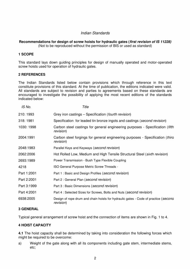
3 GENERAL Typical general arrangement of screw hoist and the connection of items are shown in Fig. 1 to 4. 4 HOIST CAPACITY 4.1 The hoist capacity shall be determined by taking into consideration the following forces which might be required to be overcome:
a) Weight of the gate along with all its components including gate stem, intermediate stems, etc;

3
PLAN
ELEVATION
b) All frictional forces comprising;
1) Wheel friction or slide friction,
2) Guide friction, and
3) Seal friction.
c) Any hydro-dynamic load, like down pull force/uplift, etc;

4
Fig. 1 Typical arrangement for manual operated screw hoist
Fig. 2 Typical arrangement of motor driven screw hoist using special worm gearbox, worm wheel mounted on thrust bearings and worm shaft with a provision of power connection on
one side and manual handle connection other side
TYPICAL
TOP OF GROOVE
ELEVATIONSIDE VIEW
PLAN
Ø 160
113.9
25
50
250
250
25
75
105
70
25
R75
Ø 160
113.9
8902
9102
SEAM LESS STEEL
TUBE PIPE OD113.9
W ALL THICKNESS
11mm
Ø62
DETAILS OF LIFTING
150 175
45
91.9

5

0

1

2
Fig. 4 Typical arrangement of stem where gate is self closing
d) Silt and ice load wherever encountered;
e) Seating pressure as prescribed in 4.4; and
f) Any other consideration specific to a particular site. 4.2 The worst combination of the above forces, during either lowering cycle or raising cycle, shall be considered.
ELEVATIONEND VIEW
W
OL
F
END VIEW ELEVATION

3
4.3 The net hoist capacity will be obtained by increasing the hoist capacity thus arrived at by 20 percent to add for the reserve hoist capacity. 4.4 The gate may be required to be given an additional downward thrust to make it seat properly on the sill to achieve the proper seal compression. While calculating the total hoist capacity during the closing cycle, the necessary closing/seating load required, when the gate is about to seat on the bottom seal, shall be greater than the value given below:
4.5 The usual lifting speed of the motor-operated screw hoist shall be 20 to 70 cm per minute and for the manually-operated screw hoist shall be governed by provision contained in 6.10. However, other values may be adopted depending upon the requirements. 5 MATERIAL AND DESIGN STRESSES 5.1 The recommended materials and design stresses for various components of screw hoist are given in Table 1. Where any material has not been specified, it shall be the best available for the purpose for which it is intended to be used and shall conform to the relevant Indian Standards.
Table 1 Material and Design Stresses for the Components of Screw Hoists
Sl. No.
Component/ Part
Recommended material
Reference Allowable design stresses Direct Bending
Shear Bearing
(1) (2) (3) (4) (5) (6) (7)
i) Stem Mild steel IS 226 IS 2062
0.4 YP 0.28 YP 0.75 YP
Forged steel IS 2004 Corrosion resistance steel
IS 1570 (Part 5)
ii) Stem nut Leaded tin bronze IS 318 ----- 0.03 UTS 0.04 UTS Aluminum Bronze IS 305 ----- 0.03 UTS 0.04 UTS
iii) Gear & pinion Forged steel IS 2004 0.4 YP 0.28 YP 0.75 YP Carbon steel IS 2062 Cast steel IS 1030
iv) Shaft keys Mild steel IS 226 IS 2062
0.4 YP 0.28 YP 0.75 YP
Forged steel IS 2004 Carbon steel IS 2062
v) Gear box base and hoist bridge
Structural steel IS 2062 0.67 YP 0.47 YP 0.75 YP
vi) Pedestal Structural steel IS 2062 0.67 YP 0.47 YP 0.75 YP Cast steel IS 1030 Cast iron IS 210
4
NOTE: For breakdown torque condition, the allowable stress shall be taken as 80 percent of the yield point stress of the material
6 DESIGN OF MECHANICAL COMPONENTS 6.1 General Requirements 6.1.1 The various components of hoist mechanism shall be so proportioned as to take the worst load coming on individual component. 6.1.2 The stress in various components of hoist shall be checked for maximum power transmission in these components, taking into account the permissible stresses as given in the relevant clauses. 6.1.3 All the hoisting machinery parts shall be checked for static as well as dynamic loads. 6.1.4 The combined stresses in various components shall be found by the following formulae:
6.2 Stem 6.2.1 General - The stem shall normally be made of mild steel or forged steel or corrosion resistant steel. It may be of galvanized or nickel chrome plated in the unthreaded portion, if so required. 6.2.2 The stem shall be provided with standard metric thread conforming to IS 4218 at one end for connection with the gate. It is normally connected to the horizontal girders and shall be required to be tightened against a minimum of two girders as per the arrangement shown in Fig. 3. The bottom end shall be provided with an additional lock nut. In case the gate does not require positive thrust for closing, pin jointing the stem to the gate may be considered, as shown in Fig 4. 6.2.3 Standard square threads or acme threads shall be cut on the stem at the other end for transmission of power. The minimum length for which the threads may be provided shall be the sum of the following:
a) Total lift of the gate,
b) Length of the nut in contact with the stem, and

5
c) Extra allowance of 300 mm. More than one start of the screw threads shall be provided in order to achieve quick linear movement. 6.2.4 The screw stem rod shall be designed for direct torsional compressive load by taking the root diameter at the minimum cross-section. The diameter so arrived at shall be checked for torsional shear stress, buckling and for combined maximum shear and maximum tensile compressive stresses. Suitable supports may be provided at intermediate points, if required. Alternatively stem with suitable seamless pipe with rigid coupling in between may be provided as shown in Fig. 2. 6.2.5 For calculating the torque transmitted by the screw threads the following formula may be used.
6.3 Nut 6.3.1 General - The nut, through which the power is to be transmitted to the stem, shall generally be of a material having lesser wear resistance then the material of the stem. 6.3.2 Square or acme threads matching with those provided on the screw stem shall be provided on the inner surface of the nut. The total number of threads to be cut on the nut shall be calculated on the basis of the total bearing area to be provided. The bearing pressure on the threads of phosphor bronze nut shall not exceed 0.04 UTS. The total length of the nut shall also be governed accordingly. 6.3.3 The number of threads provided on the basis of the bearing stress shall be checked for shear stress at the threads cross section. The minimum outside diameter of the nut shall be at least twice the minimum inside diameter. 6.3.4 Efficiency of Transmission - The efficiency of the power transmission between the nut and stem shall depend on the type of threads used. The following formulae may be used for calculating the transmission efficiency:

6
6.4 Gearing 6.4.1 General – Any of the following gear system or a suitable combination of these may be used in the screw hoist:
a) Spur gears,
b) Bevel gears, and
c) Worm and worm wheel 6.4.2 Design of Spur Gears – Unless more accurate methods are applied and called for, the spur gears shall be designed according to the formula given below:

7
6.4.3 Design of Bevel Gears 6.4.3.1 For design of the bevel gears two additional weighing factors will be used in the above formula. These are the bevel factor and the velocity factor. These are defined below: 6.4.3.2 The bevel factor shall be calculated by the formula:
6.4.3.3 The velocity factor shall be calculated by the following formula:
8
6.4.3.4 The formula in 6.4.2 for calculating root stress of the gear shall, therefore, be modified as:
6.4.4 Standard worm or helical reducer, if used, for the first stage reduction at the drive unit, shall be of high grade suitable for the service intended. Rating and efficiency of the reducer used in calculation shall be as per manufacturer’s recommendations. 6.5 Shafts, Key and Keyways 6.5.1 General - The shafts shall be designed for appropriate load/torque that is being transmitted. Shafts shall have ample strength and rigidity and adequate bearing surfaces. They shall be finished smoothly and provided with suitable changes of cross-section for easy assembly and disassembly. 6.5.2 Dimensioning of Shafts - In dimensioning the shafts with ratio of length/diameter greater than 50, the angle of twist and the revolutions/minute shall be taken into account, in addition to simple bending, pure torsion, or the combined effect of bending and torsion. The twist that shall be permitted is ¼° to ⅓° per metre. Linear deflection in the shaft shall not exceed 1.0 mm/m length. 6.5.3 All keys and keyways shall be designed in accordance with IS 2048. Keyways shall not be extended into the bearings. 6.6 Bearings 6.6.1 General - All the running shafts shall be provided with ball, roller or bush bearings. Selection of bearings shall be done on consideration of duty, load and speed of the shaft. Life of ball and roller bearings shall be calculated in accordance with the manufacturer’s recommendations. All bearings shall be easily accessible for lubrication and/or replacement. 6.6.2 Thrust Bearings - The special thrust bearings required for taking the entire hoisting/lowering load shall be provided between the nut and the pedestal body. 6.7 Couplings 6.7.1 All couplings shall be of forged steel, cast steel or cast iron and shall be designed to transmit the maximum torque that may be developed (see IS 2693). 6.7.2 Solid couplings shall be aligned in such a way that they meet accurately. Flexible couplings shall be initially aligned with the same accuracy as solid couplings. 6.8 Gear Boxes 6.8.1 Gear boxes shall be of rigid construction fitted with inspection covers and lifting handles, where necessary. The gear boxes shall be so designed that the gears may be easily removed or replaced, and shall be such that the gears remain suitably lubricated. In case of oil lubrication, facilities for oil filling and draining, connection for oil level indicator and adequate breathing arrangement shall be provided, wherever necessary. The gear boxes shall be mounted on a level surface.

9
6.8.2 The gear box shall be made of cast iron or cast steel or fabricated from mild steel. 6.9 Pedestal 6.9.1 The pedestal shall be fabricated or cast and shall be mounted on hoisting platform. The pedestal shall be designed as a column against crippling due to total hoist and shall preferably have tapered sides in order to achieve greater stability. The centre line of the operating handle shall be maintained at a height of 900 to 1000 mm from the floor. 6.10 Manual Operation 6.10.1 The manual operation arrangement shall be so designed that the continuous effect per man does not exceed a crank force of 100 N at 400 mm crank radius at a continuous rating of 24 revolutions per minute. 6.10.2 Hoists of capacity up to 7.5 tonnes may normally be provided with only manual operation arrangement unless otherwise agreed upon between the supplier and the purchaser. However, hoists of larger capacities provided with electrical operation shall also be provided with an emergency hand operation arrangement. 6.10.3 In case of electrically operated hoists, suitable electrical interlocks shall be provided to prevent operation by electrical power when the manual drive is engaged. 6.11 Gate Position Indicator 6.11.1 A separate indicator of the circular dial type or vertical scale type shall invariably be provided for each gate to show the gate position at any time. The dial or scale shall be made of a non-rusting metal or of enamelled plate or thick plastic sheet. Permanent, prominently visible markings shall be made on the dial to read every 1/10 of a metre. The gate position of ‘closed’, ‘open’ and ‘fully raised’ shall also be marked on the dial. The indicator point shall be made of non-rusting metal. Suitable locking system shall be provided to limit the over travel in lowering cycle to avoid bending / failure of stem. 6.12 The design of all the mechanical components shall be checked for breakdown torque condition. NOTE: The stresses developed in the mechanical components under breakdown torque condition shall not exceed 80 percent of the yield point for that material.
7 ELECTRICAL EQUIPMENT 7.1 General - All electrical equipments shall be suitably protected from moisture, condensation, corrosion, etc, by providing weatherproof covers and electrical heaters, wherever necessary. All equipments shall be of the best quality conforming to relevant Indian Standards. 7.2 Efficiency of System 7.2.1 The usual values of efficiencies adopted for the various elements of hoisting mechanism are given in Table 3. The overall efficiency of the system, which is the product of

10
individual efficiencies of elements, shall then be worked out. This overall efficiency of the system shall be used in calculating capacity of the electric motor.
7.3 Provision of all electrical equipments such as, motors, electro-magneto brakes, limit switches and control equipment, such as control panels, indicator lamps, relays, switches, starters, accordance with IS 6938. 7.4 Remote control equipment, if required, shall be provided to enable the operation of gates from some remote control room. Gate position indicators, suitably interlinked with local control panel, may also be provided in the remote control room. 7.5 Alternative source of electrical supply may be provided for important projects, if considered necessary.
6.3.4