Embed Size (px)
Citation preview

Speed Sort Conveyor
© Copyright Sure-Feed Engineering, Inc. 2005. All rights reserved.

2
TTaabbllee ooff CCoonntteennttss
Section I Installation Page 4 Section II Safety Locks and Warning Stickers Page 9 Safety Precautions Page 10 Machine Lock-Out Procedures Page 12 Section III General Setup Page 16 Section IV General Service Replacing Conveyor Belts Page 27 Section V Electrical Components Page 36 Wiring Diagrams Page 38 Section VI Troubleshooting Page 57

3
SSeeccttiioonn II
IInnssttaallllaattiioonn
4
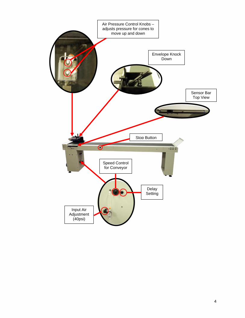
Air Pressure Control Knobs – adjusts pressure for cones to
move up and down
Sensor Bar Top View
Envelope Knock Down
Speed Control for Conveyor
Delay Setting
Input Air Adjustment
(40psi)
Stop Button

5
Speed Sort Conveyor Layout
108.25 inches
15.9
38 in
ches
Requirements Floor Space – 109” x 16” Electrical – 110VAC @ 3 amp Air – 120psi Vacuum – None Trigger Interface – Dry Contact Note: If no in-house air is available, an optional compressor (recommended by the manufacturer) must be purchased.

6
General Specifications
Item Description Operating Temperature 0 to 55 degrees Celsius (32 to 131 degrees Fahrenheit) Storage Temperature Operating Humidity 35 to 85% Relative Humidity/no condensation Storage Humidity 35 to 90% Relative Humidity/no condensation
Vibration Resistance - Direct Mounting
Conforms to IEC 68-2-6; 10-57 Hz; 0.075mm Half Amptitude 57-150 Hz: 9.8 m/s2 Acceleration Sweep Count for X, Y, Z: 10 times (80 min in each direction)
Vibration Resistance - DIN Rail Mounting
Conforms to IEC 68-2-6; 10-57 Hz; 0.035mm Half Amptitude 57-150 Hz: 4.9 m/s2 Acceleration Sweep Count for X, Y, Z: 10 times (80 min in each direction)
Shock Resistance Conforms to IEC 68-2-7: 147 m/s2 Acceleration, Action Time: 11 ms 3 times in each direction X, Y, and Z
Noise Immunity 1000 Vp-p 1 microsecond, 30-100Hz, tested by noise simulator
Dielectric Withstand Voltage
AC Power Supply Unit: 1500VAC>1 min. tested between all points, terminals, and ground. DC Power Supply Unit: 500VAC>1 min. tested between all points, terminals, and ground.
Insulation Resistance 5M ohm > at 500VDC tested between power terminals and ground Ground Class D (100 ohm or less)
Radiation Should not exceed tolerance levels other than associated with UV dryer lamps

7
Installation: Once the Speed Sort Conveyor has been removed from the shipping container, perform the following:
1. Inspect the location where the machine is to be set up. Note: The manufacturer recommends that the area be a relatively flat and smooth concrete or hard wood surface, similar substrates are acceptable. The area should be free of holes, divots, loose floorboards, etc. and not subject to retaining moisture from water seepage. Warning: In the event the floor does not meet the recommended requirements, seek an alternate location or reschedule the installation after repairs to the floor have been completed.
2. Inspect the line current at the point where the power cable of the machine is to be plugged in.
Note: Conventional wall sockets, ceiling line drops and D-Boxes should be free of cracks, rust, visible signs of heat stress and flash marks. Special Note: For installations in Europe check the condition of the voltage converter box or other voltage reducing device that may be in use. In the event of a line voltage inspection failure, report your findings to the person or persons in charge of the building and postpone the installation until corrections are made.
3. Check the line voltage to ensure that the minimum and maximum requirements are present.
110VAC @ 3 amp 50 / 60 Hertz 15 AMP Service
Note: Check voltage potential at ground to ensure the line was wired properly.
4. Position the ink jet / dryer base in the designated location then lower the leveler pads to raise
the base to a comfortable operating height, see figure 1-1.
5. Place a level in the center of the Speed Sort Conveyor and adjust the leveler pads as needed to level the machine at the desired height. Once the machine has been leveled, tighten the leveler pad lock nuts.
Turn the leveler pad counter clock-wise to lower
Turn the lock nut clock-wise to tighten
Fig. 1-1
! !

8
SSeeccttiioonn IIII
SSaaffeettyy FFeeaattuurreess
aanndd WWaarrnniinnggss

9
Safety Features: The Speed Sort Conveyor has warning labels or stickers to safeguard persons operating and/or working on or around this equipment. These are as follows: The main power or electrical box door is equipped with a safety lock that requires a specific key or tool to open.
GGeenneerraall WWaarrnniinngg Symbol indicating possible safety hazards. This label is located on the outside of the electrical box that is inside the front leg of the machine.
Fig. 2-1
Shock Hazard Symbol indicating possible shock hazard. This label is located on the outside of the electrical box that is inside the front leg of the machine.
Fig. 2-2
Mechanical Warning Symbol indicating pinch hazard.
This label is located by the Lexan that covers the knock downs for the air controls.
Fig. 2-3
Label shown at actual size
Label shown at actual size
Label shown at actual size
Note: This symbol appears as a visual alert in the text of this manual next to written warnings regarding possible safety issues and or possible machine damage that may occur as a direct result of failure to follow specific instructions as written.
!

10
Note: The warning labels and stickers are installed by the manufacturer to safeguard all persons operating and/or working on or around the machine. Removing or altering any of these labels or stickers will void any and all warranties, either real or implied, purchased or offered with the Speed Sort Conveyor. All companies connected with the manufacturing, promotion and sale of the Speed Sort Conveyor shall be held harmless for any and all injuries and damage in the event the warning labels and stickers are removed or altered.
SSaaffeettyy RReeccoommmmeennddaattiioonnss In addition to the warnings installed on the Speed Sort Conveyor by the manufacturer, the following recommendations for safe operation and maintenance of the Speed Sort Conveyor are as follows:
Any persons designated to operate, work on or near the Speed Sort Conveyor must be fully trained by a factory-authorized representative.
Do not operate or perform any type of maintenance on the Speed Sort Conveyor while under the
influence of drugs or alcohol.
Do not operate or perform any type of maintenance on the Speed Sort Conveyor in or around freestanding water.
Do not wear loose or baggy fitting shirts, shirts with bellowing sleeves, bracelets, rings,
necklaces, neckties or other loose apparel that may come into close proximity with moving parts of the machine.
Do not place any items near or over the “Emergency Stop Switches” that might inhibit or obstruct
line of sight or access to the Emergency Stop Switches. The “Emergency Stop Switches” must be clearly visible and accessible at all times.
Wear protective safety eyeglasses or goggles and use a particle mask or similar device when
cleaning off the Speed Sort Conveyor with compressed air. Alert all other persons in the area to stand a minimum of thirty (30) feet from the area where compressed air is put to such use.
Hearing protection is not required for safe operation of the Speed Sort Conveyor. Typically,
decimal levels have been found to be less than 85 decimals in machines properly maintained and in good operating condition.
All persons having hair greater than shoulder length who operate, work on or near the Speed Sort
Conveyor should keep their hair pulled back in ponytail fashion then pinned up or otherwise contained to the top of their head or confined under the back of their shirt.
Turn off the main power to the Speed Sort Conveyor before opening any of the service doors for
general cleaning and or general maintenance. Follow the “Lock Out Procedures” as stated on page 16 for extensive repairs involving disassembly of the machine either in whole or in part or replacing any of the electrical components.
Any persons working near any of the electrical motors or pump motors of the Speed Sort
Conveyor should use caution. Electrical motors give off heat; contact with or exposure to bare skin may result in burns.
The Speed Sort Conveyor was designed to sort and transport paper only. Do not attempt to sort
and/or transport materials made of or containing glass, metal, wood, plastics, liquids, foods, powders, gasses, explosives or toxic and hazardous chemicals on the Speed Sort Conveyor.
Note: The manufacturer recognizes and acknowledges that the Speed Sort Conveyor is capable of successfully running and/or transporting envelopes containing compact discs or audio cassettes, however the manufacturer and other companies connected with the promotion and sale of the Speed Sort Conveyor do not assume any responsibility for any damage to the Speed Sort Conveyor or product and shall be held harmless for any damages and or injuries resulting in this practice.
! !

11
Special Advisement: The manufacturer and other companies connected with the promotion and sale of the Speed Sort Conveyor shall be held harmless for any and all injuries sustained to any person or persons as a result of failure to comply with the recommendations for safe operation and maintenance of the Speed Sort Conveyor as shown and/or described herein.
12
Lock Out / Tag Out Procedure Before beginning extensive repairs involving disassembly of the machine either in whole or in part, performing general maintenance or replacing any of the electrical components, the machine must be locked out of service to ensure that power will not be restored to the machine while the work is being performed. To lock a machine out of service, perform the following:
1. Turn the main power switch to the off position.
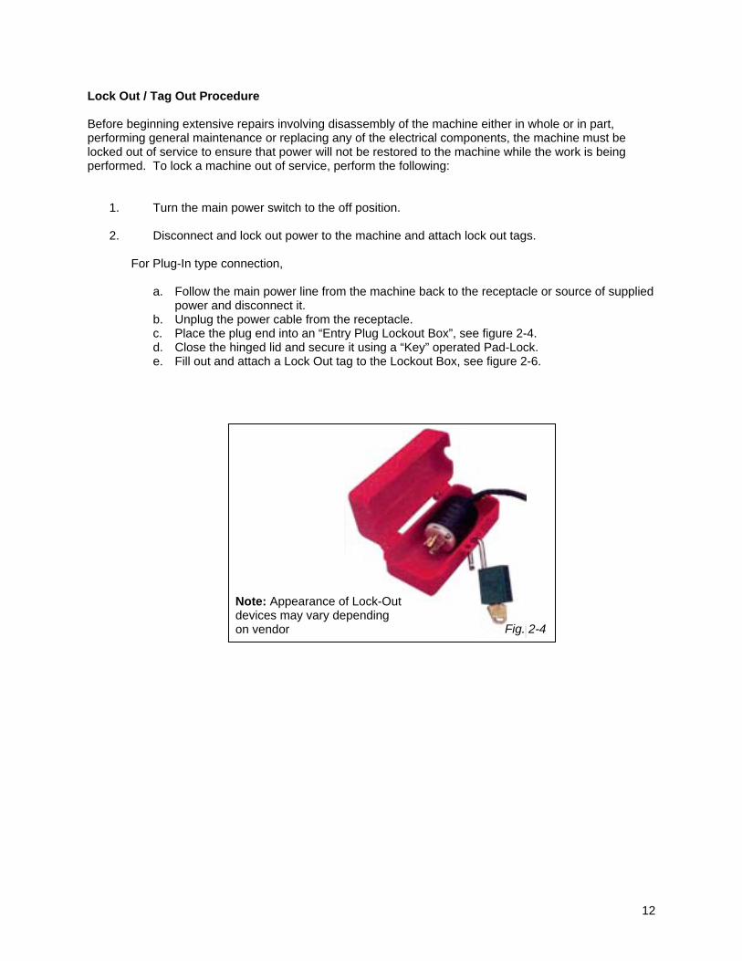
2. Disconnect and lock out power to the machine and attach lock out tags. For Plug-In type connection,
a. Follow the main power line from the machine back to the receptacle or source of supplied power and disconnect it.
b. Unplug the power cable from the receptacle. c. Place the plug end into an “Entry Plug Lockout Box”, see figure 2-4. d. Close the hinged lid and secure it using a “Key” operated Pad-Lock. e. Fill out and attach a Lock Out tag to the Lockout Box, see figure 2-6.
Fig. 2-4
Note: Appearance of Lock-Out devices may vary depending on vendor

13
For Direct Hard Wired type connection,
a. Follow the main power line from the machine back to the origin of supplied power and switch the circuit breaker to the “Off” position.
b. Place a Circuit Breaker Lockout device over the disabled circuit breaker. Follow the manufacturer’s instructions for use.
c. Using a Key-operated padlock, secure the circuit breaker lockout, see figure 2-5. d. Fill out and attach a “Lock Out” tag to the circuit breaker lockout device, see figure 2-6.
Fig. 2-5
Note: Appearance of Lock Out devices may vary depending on vendor

14
EQUIPMENT LOCKED OUT THIS TAG & LOCK TO BE REMOVED ONLY BY THE PERSON SHOWN ON BACK
EQUIPMENT LOCKED OUT BY DATE
Front View of Lock Out Tag Back View of Lock Out Tag
Fig. 2-6

15
SSeeccttiioonn IIIIII
GGeenneerraall SSeettuupp
16
Speed Sort Conveyor The Speed Sort Conveyor speed may be or optionally controlled by two factors, the speed control on the Ink Jet base or the speed control located on the Speed Sort Conveyor. The sort control can be operated by 1 of 2 methods:
1. If the Sort Conveyor is in line with the Ink Jet data, then a signal can be sent from the address data to sort.
2. If the Sort Conveyor is in line with the FlowMaster inserter with or a scan base, a Pattern Reader
must be installed to send sort signal.
For use with Ink Jet Bases: The software running the database signals the Ink Jet base when a sort break occurs, activating the sort feature which accelerates the Speed Sort Conveyor for a duration determined by the software. To set up the Speed Sort Conveyor and features, perform the following: 1. Position the edge of the Speed Sort conveyor approximately three (*3) inches from exit end of the ink
jet base/dryer base also aligning the center of the envelope knock down assembly with the center material transport belt of the ink jet base/dryer base. Note: (*3) inches stated in this step is a starting reference point for the approximate distance when running a 1-ounce, #10 envelope. The size and weight of the material as well as the selected running speed of the ink jet has a direct bearing on the distance between the Speed Sort conveyor and the exit end of the ink jet base/dryer base. Increasing or decreasing this distance may be required to accommodate the material your running.
2. Remove the envelope knock down by turning the retaining lock knob, located on the
envelope knock down mounting clamp, in a counter clock-wise direction, then lift each mounting clamp free from the stop plate.
3. Cycle the inkjet base at regular running speed and depress the feeder start button located on the left side of the inkjet base control panel. Note: Depress the feeder start button a second time to stop the feeder after 5 to 6 pieces have traveled (un-printed) to the Speed Sort conveyor.
4. Observe the material as it lands on the Speed Sort conveyor; the material should lightly strike the stop plate of the envelope knock down assembly near the surface of the conveyor bed. Note: If the material is landing on the conveyor bed or striking the stop plate too high above the conveyor bed, you may need to adjust the position of the stop plate or the position of the conveyor as described in step #1 or position and adjust the envelope knock down previously removed in step 2.
5. Return the envelope knock down (removed in step 2), to the stop plate. Position the envelope knock down approximately ¼” from the top and bottom edge of the material, and tighten the Retaining Lock Knob by turning it in a clockwise direction.
6. Adjust the knock down strap. Once the job has been started and running speed has been
established, watch the finished product as it lands on the Speed Sort conveyor and look for these occurrences:
a. The material strikes the stop plate so hard that it bounces back before landing on the conveyor.
Adjust the knock down strap to apply greater resistance to the material, (slowing it down) before it strikes the stop plate. Do this by turning the adjustment knobs, on the envelope knock down, in a clock-wise direction.
b. The material lands on the conveyor before reaching the stop plate. Adjust the knock down strap to apply less resistance to the material, (allowing it to maintain speed) to reach the strikes the stop plate. Do this by turning the adjustment knobs, on the envelope knock down, in a counter clock-wise direction.

17
PPaatttteerrnn MMaattcchh RReeaaddeerr
GGeenneerraall SSeett--UUpp PPrroocceedduurree
© Copyright, Sure-Feed Engineering, Inc. 2005
18
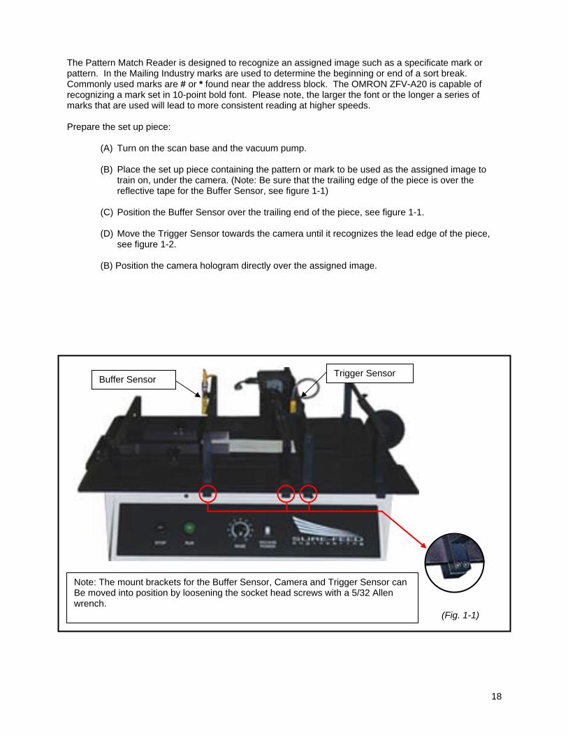
The Pattern Match Reader is designed to recognize an assigned image such as a specificate mark or pattern. In the Mailing Industry marks are used to determine the beginning or end of a sort break. Commonly used marks are # or * found near the address block. The OMRON ZFV-A20 is capable of recognizing a mark set in 10-point bold font. Please note, the larger the font or the longer a series of marks that are used will lead to more consistent reading at higher speeds. Prepare the set up piece:
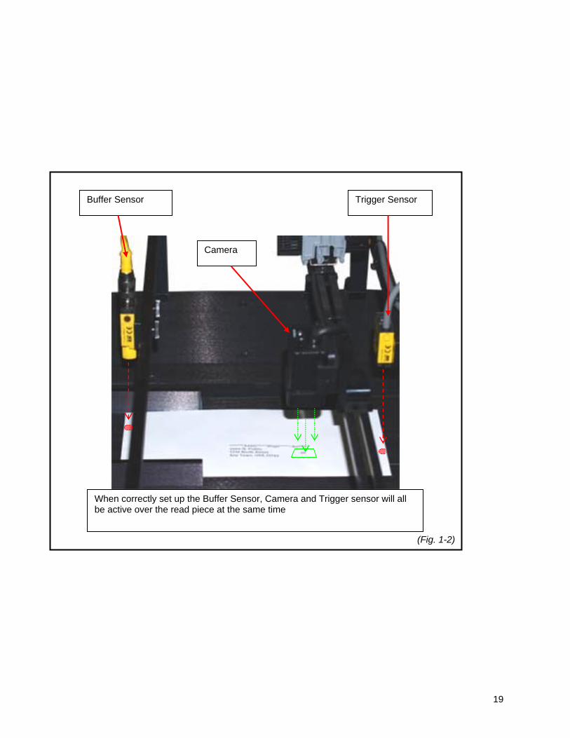
(A) Turn on the scan base and the vacuum pump. (B) Place the set up piece containing the pattern or mark to be used as the assigned image to
train on, under the camera. (Note: Be sure that the trailing edge of the piece is over the reflective tape for the Buffer Sensor, see figure 1-1)
(C) Position the Buffer Sensor over the trailing end of the piece, see figure 1-1. (D) Move the Trigger Sensor towards the camera until it recognizes the lead edge of the piece,
see figure 1-2. (B) Position the camera hologram directly over the assigned image.
Buffer Sensor Trigger Sensor
Note: The mount brackets for the Buffer Sensor, Camera and Trigger Sensor can Be moved into position by loosening the socket head screws with a 5/32 Allen wrench.
(Fig. 1-1)
19
When correctly set up the Buffer Sensor, Camera and Trigger sensor will all be active over the read piece at the same time
Buffer Sensor
Camera
Trigger Sensor
(Fig. 1-2)

20
Paper Sensor Adjustment The buffer sensor is located at the “In-Feed” end of the scan base, over a pre-set reflective surface.
This sensor is set to detect and confirm the presence of paper before passing under the pattern reader. This sensor does not normally need to be adjusted for each job, once the setting has been made, it should remain set unless otherwise disrupted. In the event the settings have been disrupted, perform the following:
1. Position the sensor directly over the center of the reflective surface by turning the thumbscrew in
the sensor mounting block in a counter clock-wise direction and sliding the sensor assembly across the sensor support bar. Once the desired position is acquired, tighten the thumbscrew in the sensor-mounting block in a counter clock-wise direction.
2. Place a blank piece of white paper on the vacuum belt directly under the paper sensor.
3. Using a small flat blade screwdriver, remove the pan head screw in the plastic cover located on
the sensor next to the electronic cable connection, see figure 1-3. Note: Depending on the scan base model, this sensor may have a detachable screw type cable connection or may have a hard wire cable connection. The sensitivity adjustments for both models are identical.
4. Set the “Light / Dark” pot setting; using a small flat blade screw driver, slowly and very carefully
turn the pot setting, located next to the electronic cable connection, in a counter clock-wise direction until full range of motion is felt, see figure 1-4. Note: If this adjustment is performed correctly, the screw driver slot in the pot setting should be pointing towards the “DO” in the range scale next to the pot setting. Caution: The stop point of this pot setting can be damaged if excessive force is applied.
5. Set the “Gain” pot setting by performing the following:
a. Using a small flat blade screwdriver, slowly and carefully turn the pot setting located furthest from the electronic cable connection in a counter clock-wise direction until full range of motion is felt, see figure 1-4. The red LED indicator light should be off at this point.
b. Using a small flat blade screwdriver, slowly and carefully turn the pot setting located furthest from the electronic cable connection in a clock-wise direction until the red LED light comes on, continue turning the pot setting in a clock-wise direction another half turn.
6. Return the plastic cover, removed in step (3) to its original position.
!

21
The trigger sensor is located at the “Out-Feed” end of the scan base and is positioned over the center
vacuum belt. This sensor is set to detect and confirm the presence of the leading edge of the read piece and should be positioned to become active when the camera is directly over the sort mark. This sensor does not normally need to be adjusted for each job, once the setting has been made, it should remain set unless otherwise disrupted. In the event the settings have been disrupted, perform the following:
7. Position the sensor directly over the center vacuum belt surface by turning the thumbscrew in the
sensor mounting block in a counter clock-wise direction and sliding the sensor assembly across the sensor support bar. Once the desired position is acquired, tighten the thumbscrew in the sensor-mounting block in a counter clock-wise direction.
8. Using a small flat blade screwdriver, remove the pan head screw in the plastic cover located on
the sensor next to the electronic cable connection, see figure 1-3. Note: Depending on the scan base model, this sensor may have a detachable screw type cable connection or may have a hard wire cable connection. The sensitivity adjustments for both models are identical.
9. Set the “Light / Dark” pot setting; using a small flat blade screw driver, slowly and very carefully
turn the pot setting, located next to the electronic cable connection, in a clock-wise direction until full range of motion is felt, see figure 1-5. Note: If this adjustment is performed correctly, the screw driver slot in the pot setting should be pointing towards the “LO” in the range scale next to the pot setting. Caution: The stop point of this pot setting can be damaged if excessive force is applied.
10. Set the “Gain” pot setting by performing the following:
a. Using a small flat blade screwdriver, slowly and carefully turn the pot setting located furthest from the electronic cable connection in a counter clock-wise direction until full range of motion is felt, see figure 1-5. The red LED indicator light should be on at this point.
b. Place a white piece of paper under the sensor at this time. c. Using a small flat blade screwdriver, slowly and carefully turn the pot setting located
furthest from the electronic cable connection in a clock-wise direction until the red LED light goes off.
11. Return the plastic cover, removed in step (3) to its original position.
!

22
Remove the plastic cover from the sensor to gain access to the pot settings.
(Sensor shown has detachable electrical cable fitting)
Plastic Cover
Fitting for electronic cable
Fig. 1-3

23
View of Detachable Cable style Sensor (Typically used to read over reflective tape) (Shown in actual orientation as it appears on the scan base)
Fig. 1-4
4 Pin detachable cable fitting
Light / Dark Pot Setting
Red LED Light
Gain Pot Setting

24
GGAAIINN +
-
DO
LLOO
View of Hard Wired Cable style Sensor (Typically used to read over dark surfaces) (Shown in reverse orientation as it appears on the scan base)
Fig.1-5
Light / Dark Pot Setting
Hard wired electronic cable
Gain Pot Setting
Red LED Light

25
To set up and operate the Pattern Match Reader, perform the following: Step-1. Open the access cover to the control keys and menu selector switch, see figure 1-6.
(Fig. 1-6)
Flip cover door down to open
Control Keys & Menu Selection Switch

26
Step-2. Place the Mode select switch to “MENU” and the view select switch to “EXP” (expanded view),
see figure 1-7.
Mode select switch set on “MENU”
View select switch set on “EXP”
Expanded menu shown on view screen
(Fig. 1-7)

27
Step-3. Using the Control Keys, move the red outline indicator over the “SYS 1” menu and press the “Set”
button to enter the menu, see figure 1-8. Step-4. The System 1 menu consists of the following items, refer to figure 1-9;
(1) BANK menu (This menu is not applicable)
(2) IMAGE RATE menu Use Directional Control Keys to highlight (in white) in white, then press “SET” button to enter. Use Directional Control Keys to highlight (in white) the “NORMAL” option, then press “SET” button to return to System 1 menu
(3) MEASURE TYPE menu
Use Directional Control Keys to highlight (in white), then press “SET” button to enter. Use Directional Control Keys to highlight (in white) the “TRIGGER” option, then press “SET” button to return to System 1 menu
(4) TEACH TYPE menu
Use Directional Control Keys to highlight (in white), then press “SET” button to enter. Use Directional Control Keys to highlight (in white) the “STATIONARY” option, then press “SET” button to return to System 1 menu
(5) ECO MODE menu (This menu is not applicable) Once the options in the System 1 menu have been set, press the “ESC” button to return to the main menu, see figure 1-9.
(Fig. 1-8)
Use the directional control keys to move the outline indicator
Press the “Set” button to enter the selected menu
System 1 shown with the outline indicator

28
SYSTEM 1 MENU
Press “ESC” button to return to main Systems menu
Use Directional Control Keys to scroll through menu items and options
Press “SET” button to enter menu item. Press “Set” button again to enter option and return to this menu (Fig. 1-9)

29
Step-5. Using the Control Keys, move the red outline indicator over the “SYS 2” menu and press the “Set”
button to enter the menu, see figure 1-10.
(1) OUT PUT menu Use Directional Control Keys to highlight (in white) this menu in white and press the “Set” button to enter(This menu has five (5) separate topics, two (2) of these need to be set.)
1- ON STATUS = Use Directional Control Keys to highlight (in white),
then press “SET” button to enter. Use Directional Control Keys to highlight (in white) “OK ON”, then press “Set” button to return to OUT PUT menu.
2- ONE SHOT = Use Directional Control Keys to highlight (in white), then press “SET” button
to enter. Use Directional Control Keys to highlight (in white) “ON”, then press “ESC” button to return to OUT PUT menu.
(Fig. 1-10)
Use the directional control keys to move the outline indicator
Press the “Set” button to enter the selected menu
System 2 shown with the outline indicator

30
3- ON DELAY = Setting NONE
4- OFF DELAY = Use Directional Control Keys to highlight (in white) in white, then press “SET” button to enter. Use Directional Control Keys to highlight (in white) “Number Area”. Press the “SET” button to highlight (in white) the number column you wish to adjust, then use the up and down Directional Control Keys to increase or decrease number value to 50, then press “ESC” to return to OUT PUT menu, see figure 1-11.
5- OUT PUT TIME = Setting 50 (Exception: When using an
“Edge Marker”, triggered by this device, enter 150 to 250. The higher the number, the longer the mark will be.)
Use the up and down directional keys to increase or decrease the number value
Press the “SET” button to highlight the number column being adjusted
Press the “ESC” button to return to the previous menu
(Fig. 1-11)

31
(2) TEACH IMAGE menu Use Directional Control Keys to highlight (in white), then press “SET” button to enter. Use Directional Control Keys to highlight (in white) the “THROUGH” option, then press “ESC” button to return to System 2 menu
(3) I/O MON menu (This menu is not applicable) (4) COM menu (This menu is not applicable)
(5) ALL CLEAR menu (This menu is not applicable)
(6) MEAS CLEAR menu (This menu is not applicable) (7) VERSION menu (This menu is not applicable) Once the options in the System 2 menu have been set, press the “ESC” to return to the main menu. Step-6. Using the Control Keys, move the red outline indicator over the “TEACH” menu and press the
“Set” button to enter the menu, see figure 1-12.
(Fig. 1-12)
Use the directional control keys to move the outline indicator
Press the “Set” button to enter the selected menu
System 2 shown with the outline indicator

32
The “TEACH” menu consists of the following items;
(1) ITEM menu Use Directional Control Keys to highlight (in white) this menu, then press “SET” button to enter. (The “ITEM” menu contains 7 submenus, see figure 1-13.) Use Directional Control Keys, move the red outline indicator over the “PTRN” submenu and press the “Set” button to enter the menu. This submenu has two topics. Use Directional Control Keys, move the red outline indicator over the “MATCH”, then press the “ESC” button to return to the “ITEM” menu and press the “ESC” button a second time to return to the main “TEACH” menu.
Press the “Set” button to enter the selected menu
Use the directional control keys to move the outline indicator
“PTRN” shown with outline indicator
Use the directional control keys to move the outline indicator
Press “ESC” button to return to main Systems menu
(Fig. 1-13)

33
(2) MOVE menu
Use Directional Control Keys to highlight (in white), then press “SET” button to enter. Press and hold down the Directional Control Keys to move the camera view field hologram to center the intended pattern or mark to be read, press the “ESC” button to return to the “TEACH” menu, see figure 1-14.
(Fig. 1-14)
Press “ESC” button to return to main TEACH menu
Use the directional control keys to move the view field hologram
TEACH/MOVE MOVE
Move the view field hologram to center the pattern or mark being used

34
(3) SIZE menu Use Directional Control Keys to highlight (in white), then press “SET” button to enter. Use Directional Control Keys to increase or decrease the size of the camera view field. Press the “ESC” button to return to the “TEACH” menu, see figure 1-15.
TEACH/SIZE SIZE
Press “ESC” button to return to main TEACH menu
Change the size of the view field hologram to best fit the pattern or mark being used
Use the directional control keys to increase or decrease the view field hologram (Fig. 1-15)

35
Step-7. Press the orange “TEACH / VIEW button to train the camera to recognize the pattern or mark.
(Note: The camera uses a red photo strobe when reading, you may see this photo strobe pulse very quickly while the camera is training on the assigned image. Once the camera has completed the training process, the red photo strobe will stop pulsing and the light will appear to be constant. You will also notice that the red “OUT PUT” LED on the controller is now on, see figure 1-16.)
Press the “TEACH / VIEW” to train the camera to recognize the assigned image
The Out Put LED till come on after the camera is trained to recognize the assigned image
(Fig. 1-16)

36
Step-8. Place the Mode switch to “ADJ as shown in figure 1-17. (The read threshold will appear at the
bottom of the menu screen.) Step-9. Using the up and down Directional Control Keys, adjust the threshold tolerance to approximately
20 degrees less than the readable threshold shown on the display, see figure 1-17. (This should accommodate for any slight variation that may occur while the pattern match reader is in operation reading a moving mark.) (Note: If the tolerance is set higher than the readable percentage, the “Threshold Percentage Bar” will appear Red. When the tolerance of the threshold is set correctly, the “Threshold Percentage Bar” will appear Green.)
Once this general set has been completed, it will only be necessary to perform Steps 6 through 9 to train the Pattern Match Reader to recognize new marks or patterns when changing between jobs.
(Fig. 1-17)
Place Mode switch to “ADJ”
Threshold Percentage Bar
Use the up and down Directional Control Keys to adjust the threshold tolerance

37
Step-10. Test the set up in the following manner:
(A) Place the Mode Switch to “Run”, see figure 1-18.
(B) With the vacuum pump “On” manually place one piece, containing a sort mark, on the
vacuum belt of the scan base, between the material guides to the left of the “Buffer Sensor”.
(C) Press the “Run” button located on the scan base control console to run the test piece
under the camera at normal operating speed.
(D) Check the read rate indicated on the display, it should be registering approximately 20 degrees above the threshold previously set in “Step – 9”. (Note: In the event the read rate is to close to the set threshold, less than 10 degrees, repeat “Steps 6 through 9.)
(E) Repeat this test using a piece that does not have a sort mark, it should have a failure
read rate approximately 20 degrees or more, below the threshold previously set in “Step – 9”.
(F) After the set up has been completed depress the red “Re-Set” button located on the
“Sort Select / Reset” module two times, see figure 1-19. Pressing the re-set button will clear the buffer sensor on the scan base and the buffer sensor on the sort conveyor. (Note: After the job has been started you find that the sort cones trigger several pieces after the piece with the sort mark has passed, it means that the buffer sensors are not registering on the same piece. Pressing the re-set button on the “Sort Select / Reset” module will clear both buffer sensors so they will register on the same piece.)
(Fig. 1-18)
Place Mode switch to “RUN”
Threshold Percentage Bar

38
Speed Sort Conveyors purchased especially for use with pattern mark readers also come equipped with a “Sort Select / Reset” module, see figure 1-19. The sort module can be set to trip the sort cones on the actual mail piece printed with the sort mark, typically the “First” piece in a sort break. In contrast it can also be set to trip the sort cones after the last piece in the sort break in the event the last piece carries the actual sort mark.
Fig. 1-19
Sort Mode – Flip switch to “First Piece” to trip the sort cones
on the actual mail piece printed with the sort mark or flip switch to “Last Piece” if you want it to trip the sort cones after the last
piece in the sort break in the event the last
piece carries the actual sort mark.
Reset Button

39

40
For use with Pattern Reader: The pattern reader recognizes a specified mark or series of specified letters or numbers placed on the either the first or last mailing piece as a sort break. When the sort break occurs the pattern reader activates the sort feature in the PLC, (see page ), which will engage the sort separation cones on the Speed Sort Conveyor. To set up the Speed Sort Conveyor using a pattern reader, perform the following: 1. Position the edge of the Speed Sort conveyor approximately three (*3) inches from exit end of the
scanner base also aligning the center of the envelope knock down assembly with the center material transport belt of the scanner base. Note: (*3) inches stated in this step is a starting reference point for the approximate distance when running a 1-ounce, #10 envelope. The size and weight of the material as well as the selected running speed of the scanner base has a direct bearing on the distance between the Speed Sort conveyor and the exit end of the scanner base. Increasing or decreasing this distance may be required to accommodate the material you are running.
2. Remove the envelope knock down by turning the retaining lock knob, located on the
envelope knock down mounting clamp, in a counter clock-wise direction, then lift each mounting clamp free from the stop plate.
3. Turn on the scanner base by depressing the green button located on the left side of the control panel, then cycle the inserter at regular running speed until 5 or 6 pieces have fed out and landed on the Speed Sort Conveyor.
4. Observe the material as it lands on the Speed Sort conveyor; the material should lightly strike the
stop plate of the envelope knock down assembly near the surface of the conveyor bed. Note: If the material is landing on the conveyor bed or striking the stop plate too high above the conveyor bed, you may need to adjust the position of the stop plate or the position of the conveyor as described in step #1 or position and adjust the envelope knock down previously removed in step #2.
5. Return the envelope knock down (removed in step 2), to the stop plate. Position the envelope knock down approximately ¼” from the top and bottom edge of the material, and tighten the Retaining Lock Knob by turning it in a clockwise direction.
6. Adjust the knock down strap. Once the job has been started and running speed has been
established, watch the finished product as it lands on the Speed Sort conveyor and look for these occurrences:
a. The material strikes the stop plate so hard that it bounces back before landing on the conveyor.
Adjust the knock down strap to apply greater resistance to the material, (slowing it down) before it strikes the stop plate. Do this by turning the adjustment knobs, on the envelope knock down, in a clock-wise direction.
b. The material lands on the conveyor before reaching the stop plate. Adjust the knock down strap to apply less resistance to the material, (allowing it to maintain speed) to reach the strikes the stop plate. Do this by turning the adjustment knobs, on the envelope knock down, in a counter clock-wise direction.
Once the material path has been smoothly established out to the Speed Sort Conveyor, set up the pattern reader by performing the following:
a. Set the dip switches located at the bottom of the amplifier to the following configuration: Switch Position A.T. On / Off OFF – (down)
WD / NM OFF – (down) TMR ON – (up)
/ = OFF – (down) see figure 3-1.
=

41
b. Set the Read Mode to “PATT”, see figure 3-1.
c. Place a sample of the printed sort mark in the center of the green hologram emitted by the pattern reader camera, see figure 3-1a.
4
7
OMRON
F10-C20
LEVEL
2 3
5 6
8
THRESHOLD
PATT
PLNOUT
PATT
DEV
AVE
PLN
1
PATT-PLN PATT
A.T. ON
A.T. OFF
WD TMR
=NMMADE IN JAPAN
#
TEACH/ DISPLAY
SELECT
MON
TEACH RUN
TMR dipswitch in the up position
Read mode dipswitch set to PATT
Select mode switch set to “TEACH”
Hold “Teach / Display button down to train to maximum Level
Fig. 3-1
Fig.3- 1a
***** AUTO 3 DIGIT 337 John Q. Public 4275 1st Ave. North Anytown, USA. 55337 IIIIIIIIIIIIIIIIIIIIIIIIIIIIIIIIIIIIIIIIIIIIIIIII
Postage PAID Permit 04
Optimum Range for Mark Alignment

42
Note: Any font type can be used however the larger and bolder the font is the more accurate it will be read. Minimum 10-point font is required. For best read results the camera should be positioned approximately 5” above the read area.
d. Turn the Mode Select switch to “TEACH”, see figure 3-1.
e. Depress the “TEACH/DISPLAY” button and hold it down until all of the Green Level
indicator LEDs have lit up to level 8, see figure 1. Note: If the level indicators do not light up to level 8, turn the “Mode Select” switch from “TEACH” to “MON”, then depress the “SELECT” UP button until the Red Threshold LEDs have advanced in range for greater sensitivity, see figure 3-2.
4
7
OMRON
F10-C20
LEVEL
2 3
5 6
8
THRESHOLD
PATT
PLNOUT
PATT
DEV
AVE
PLN
1
PATT-PLN PATT
A.T. ON
A.T. OFF
WD TMR
=NMMADE IN JAPAN
#
TEACH/ DISPLAY
SELECT
MON
TEACH RUN
To adjust sensitivity, turn Mode switch to “MON”
Press the “UP” button to increase sensitivity
Fig. 3-2

43
f. Once the amplifier has been trained to recognize the sort mark, turn the Mode Select switch to “RUN”, see figure 3-3, then test the setup by feeding a printed sort mark under the pattern reader and observing the movement of the sort cones.
Speed Sort Conveyors purchased especially for use with pattern mark readers also come equipped with a “Sort Select / Reset” module, see figure 3-4. The sort module can be set to trip the sort cones on the actual mail piece printed with the sort mark, typically the “First” piece in a sort break. In contrast it can also be set to trip the sort cones after the last piece in the sort break in the event the last piece carries the actual sort mark.
4
7
OMRON
F10-C20
LEVEL
2 3
5 6
8
THRESHOLD
PATT
PLNOUT
PATT
DEV
AVE
PLN
1
PATT-PLN PATT
A.T. ON
A.T. OFF
WD TMR
=NM MADE IN JAPAN
#
TEACH/ DISPLAY
SELECT
MON
TEACH RUN
Fig. 3-3
Turn the Mode switch to “Run” to test the setup and run the job

44
Reset Button
Sort Mode – Flip switch to “First Piece” to trip the sort cones
on the actual mail piece printed with the sort mark or flip switch to “Last Piece” if you want it to trip the sort cones after the last
piece in the sort break in the event the last
piece carries the actual sort mark.
Fig. 3-4
45
Paper Sensor Adjustment The paper sensor is located at the “In-Feed” end of the scan base, over a pre-set reflective surface.
This sensor is set to detect and confirm the presence of paper before passing under the pattern reader. This sensor does not normally need to be adjusted for each job, once the setting has been made, it should remain set unless otherwise disrupted. In the event the settings have been disrupted, perform the following:
12. Position the sensor directly over the center of the reflective surface by turning the thumbscrew in
the sensor mounting block in a counter clock-wise direction and sliding the sensor assembly across the sensor support bar. Once the desired position is acquired, tighten the thumbscrew in the sensor-mounting block in a counter clock-wise direction.
13. Place a blank piece of white paper on the vacuum belt directly under the paper sensor.
14. Using a small flat blade screwdriver, remove the pan head screw in the plastic cover located on
the sensor next to the electronic cable connection, see figure 3-5. Note: Depending on the scan base model, this sensor may have a detachable screw type cable connection or may have a hard wire cable connection. The sensitivity adjustments for both models are identical.
15. Set the “Light / Dark” pot setting; using a small flat blade screw driver, slowly and very carefully
turn the pot setting, located next to the electronic cable connection, in a counter clock-wise direction until full range of motion is felt, see figure 3-6. Note: If this adjustment is performed correctly, the screw driver slot in the pot setting should be pointing towards the “DO” in the range scale next to the pot setting. Caution: The stop point of this pot setting can be damaged if excessive force is applied.
16. Set the “Gain” pot setting by performing the following:
a. Using a small flat blade screwdriver, slowly and carefully turn the pot setting located furthest from the electronic cable connection in a counter clock-wise direction until full range of motion is felt, see figure 3-6. The red LED indicator light should be off at this point.
b. Using a small flat blade screwdriver, slowly and carefully turn the pot setting located furthest from the electronic cable connection in a clock-wise direction until the red LED light comes on, continue turning the pot setting in a clock-wise direction another half turn.
17. Return the plastic cover, removed in step (3) to its original position.
!

46
Remove the plastic cover from the sensor to gain access to the pot settings.
(Sensor shown has detachable electrical cable fitting)
Plastic Cover
Fitting for electronic cable
Fig. 3-5

47
View of Detachable Cable style Sensor (Shown in actual orientation as it appears on the ink jet base)
Fig. 3-6
4 Pin detachable cable fitting
Light / Dark Pot Setting
Red LED Light
Gain Pot Setting

48
GGAAIINN +
-
DO
LLOO
View of Hard Wired Cable style Sensor (Shown in reverse orientation as it appears on the ink jet base)
Fig.3-7
Light / Dark Pot Setting
Hard wired electronic cable
Gain Pot Setting
Red LED Light

49
SSeeccttiioonn IIVV
GGeenneerraall SSeerrvviiccee

50
Conveyor belt replacement:
1. Turn off the power to the ink jet base/dryer base.
2. Unplug the power cable, the communication cable, and the airline from the Speed Sort Conveyor.
(Move the single conveyor away from the ink jet base/dryer base or the inserter in order to provide room to work.)
3. Remove the Envelope Knock Down / Stop Plate assembly:
a. Remove both of the retaining lock knobs by turning them in a counter clock-wise direction, see figure 4-1.
b. Lift the envelope knock down / stop plate assembly off of the conveyor bed and set it aside.
4. Remove the front leg cover:
a. Using a 1/8” Allen wrench, remove the two button head Allen screws located on the side of the front leg assembly, see figure 4-2.
b. Pull the left side (same side as the button head Allen screws removed in step a) of the leg cover back to clear the leg assembly, then shift the cover to the left to get the inside screws free of the right side of the leg assembly and continue pulling the cover free of the leg assembly, see figure 4-2. Note: the top part of this cover is slotted and fits over the conveyor belt. Use caution when removing this belt to avoid damaging the belt.
Remove both retaining knobs to remove stop plate assembly
Fig.4- 1

51
5. Remove both end cap covers from the conveyor:
a. Using a 5/32” Allen wrench, remove the two (2) button head Allen screws located at each side of the end cap cover, see figure 4-2.
b. Pull each end cap straight out from the conveyor.
Remove these two button head screws to remove leg cover
Front Leg Assembly
Front Leg Cover removed Fig. 4-2
View of Rear End Cap
Remove two button head screws from each side of both end caps to remove the end caps
Fig. 4-3

52
6. Loosen the conveyor belt: a. Using a 5/32” Allen wrench loosen the four (4) button head Allen screws located on each side
of the conveyor bed near the material stop post at the rear end of the conveyor, see figure 4-4.
7. Using a 7/16” open end wrench, loosen the retaining nut located on each of the conveyor belt
tensioner found inside the conveyor bed above the rear leg assembly, see figure 4-5.
Loosen all four button head screws on both sides of the conveyor over rear leg section
Fig. 4-4
Loosen all four button head screws on both sides of the conveyor over rear leg section

53
8. Using a 7/16” open-end wrench, loosen the conveyor belt tension adjustment bolt by turning it in a counter clock-wise direction, see figure 4-5.
9. Using a 7/16” open end wrench, loosen the three (3) hex head bolts located under the conveyor
bed, found on the left side (motor side) of the front leg section, see figure 4-7.
Fig.4-5
Belt tension adjustment retaining nut
Belt tension adjustment bolt
Note: The illustration shown is not actual size
Loosens in this direction
Fig. 4-6
View Back End of Conveyor with End Cap removed

54
Note: There is a 7/16” retaining nut under each hex head bolt that will need to be held in place in order to loosen the bolts. Do not remove these bolts, just loosen them.
10. Using a 7/16” open end wrench, remove the three (3) hex head bolts located under the conveyor
bed, found on the right side of the front leg section, see figure 4-8. Note: There is a 7/16” retaining nut under each hex head bolt that will need to be held in place in order to loosen the bolts.
11. Using a 7/16” open end wrench, loosen the two (2) hex head bolts located under the conveyor bed, found on the right side of the rear leg section, see figure 4-9. Note: There is a 7/16” retaining nut under each hex head bolt that will need to be held in place in order to loosen the bolts. Do not remove these bolts, just loosen them.
View Left Side Front Leg Assembly
Fig.4-7 Hold nuts stationary while loosening bolts
Note: Third bolt is obscured by pulley
Fig.4-8
View Right Side Front Leg Assembly
Hold nuts stationary while removing bolts

55
12. Using a 7/16” open end wrench, remove the two (2) hex head bolts located under the conveyor bed, found on the left side of the rear leg section, see figure 10. Note: There is a 7/16” retaining nut under each hex head bolt that will need to be held in place in order to loosen the bolts.
13. Slide the old conveyor belt off of the rollers towards the side of the conveyor that the bolts were removed from in steps 10 and 12.
14. Lift the front end of the conveyor bed at the side where the bolts were removed in step 10 and slide the belt through the space between the conveyor bed and the leg section. Warning: This step may be awkward or cumbersome, acquire assistance for lifting to avoid possible injury.
Fig.4-10
View Left Side Rear Leg Assembly
Hold nuts stationary while removing bolts
View Right Side Rear Leg Assembly
Fig.4-9 Hold nuts stationary while loosening bolts
!

56
15. Lift the rear end of the conveyor bed at the side the bolts were removed in step 12 and slide the
belt through the space between the conveyor bed and the leg section, see figure 4-11. Warning: This step may be awkward or cumbersome, acquire assistance for lifting to avoid possible injury.
16. Place the new belt on the conveyor in the same manner in which the old belt was removed in steps 13 -
15.
17. Tension the new conveyor belt:
a. Using the a 7/16” open-end wrench turn the adjustment bolts (refer to figure 4-5) in a clock-wise direction until the center of the button head retaining screws, (loosened in step 6, figure 4-4) are approximately 3/4” to 1” from the back edge of the adjustment slot. Warning: Do not over tighten the conveyor belt. Over tightening the conveyor belt may result in damage to the conveyor drive motor and shafts.
b. When the adjustment is completed on both sides of the conveyor, tighten the hex head retaining
screws using a 5/32” Allen wrench, see figure 4-5. c. Using a 7/16” open-end wrench tighten the belt tension adjustment-retaining nut, see figure 4-5.
Slide belts in this direction
Fig. 4-11
View Shows Back End of Conveyor with
End Cap removed.
Lift the conveyor bed just enough to get the belt under.
!
!

57
18. Re-attach the conveyor bed to the leg sections, following steps 10 through 13 in reverse order.
19. Return the Stop Pins removed in step 8 to their original position and secure them using the hex head
Allen screws and flat washer also removed in this step.
20. Plug the conveyor back into the ink jet / dryer base, refer to step 2.
21. Turn the power “On” to the ink jet / dryer base and run the machine, observe the conveyor belt and the manner they track on the conveyor belt rollers. Note: If the belts track off of the conveyor rollers, further tension adjustments may be needed, refer to step 17.
22. Once the conveyor belt have proven to track straight, finish reassembling the conveyor following steps 3
through 5 in reverse order.
Approximately 3/4” to 1”Fig. 4-12
View Button head tension retaining screws after belt tension has been properly set.

58
SSeeccttiioonn VV
EElleeccttrriiccaall aanndd
WWiirriinngg

59
A
Speed Sort Conveyor
B
C
D
E
F
G
H
II

60
Item Component Function A 90 Volt DC Motor Cable Supply voltage output B Relay/Switch To start and stop conveyor C Input side of IO PCB Sync/Delay Pot D 16 VAC Input/ IO PCB Input Voltage E Relay/Swtich For solenoid operation F Speed Pot Controls Controls speed of conveyor G Factory Set Min Speed Control Fine tunes min speed H Factory Set Max Speed Control Sets max speed of conveyor I Transformer Input voltage for IO PCB
F
G
H

61

62

63
Black
Brown
Blue
Black
White/Black
Black
Red
Pot Face

64
Blue
Brown
65
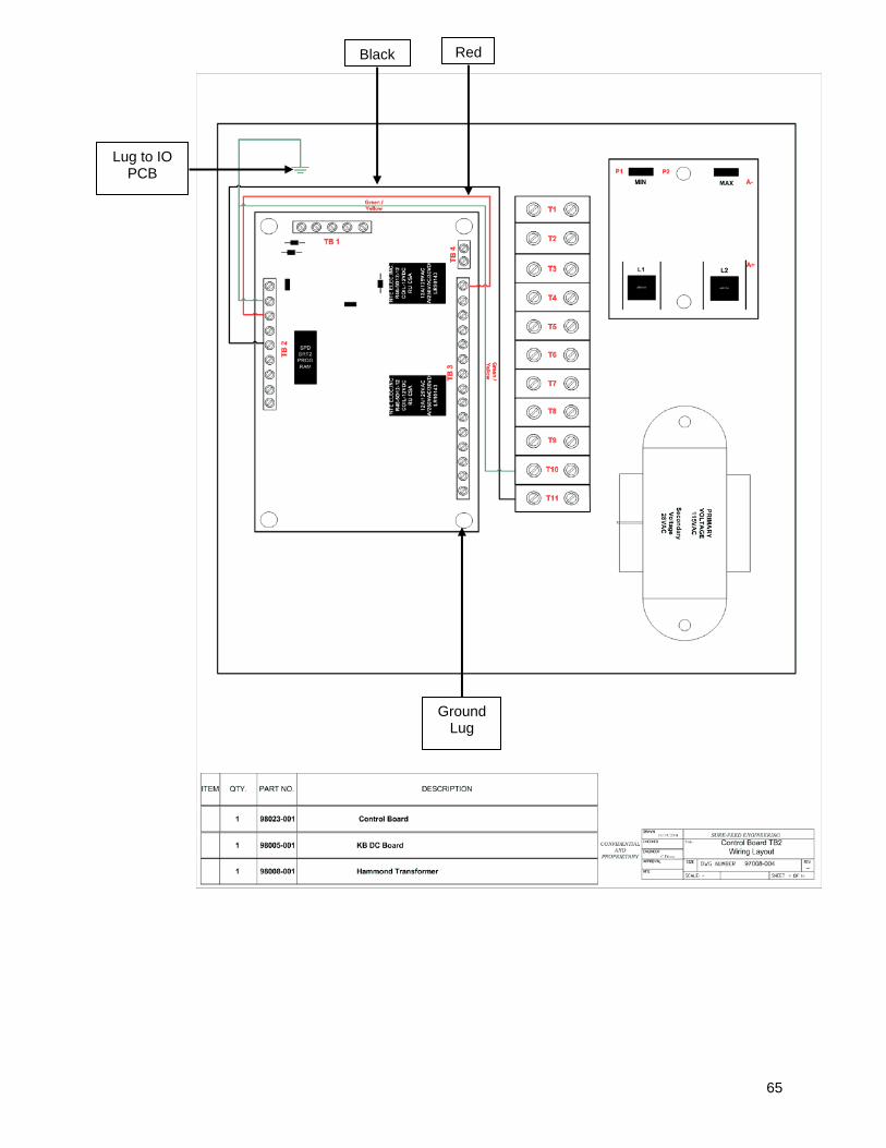
Lug to IO PCB
Black Red
Ground Lug

66
Red

67

68
Black
Red
Black
Red

69
+12V DC Switched
0V DC
SYNC
GND

70

71

72
73
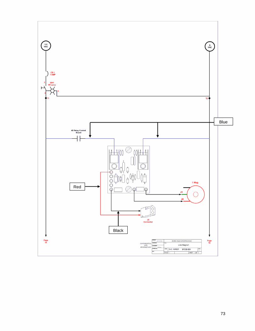
Blue
Red
Black
74

75
White/Red
Red
Blue
Brown
Black
Black
Blue
Brown

76
Blue or Green
Black

77

78
91
Dionne
3/18/2004
Title
SUR
E-F
EE
D E
NG
INE
ER
ING
CO
NFI
DE
NTI
AL
AN
DPR
OPR
IETA
RY
5/5/2005
MIT
SU
BIS
HI
ME
LSE
C
0 1
2 3
4 5
6 7 IN
PO
WER
RU
NE
RR
OR
0 1
2 3
4 5 O
UT
FX
-14M
R1S
Blac
k
Whi
te
Gre
en
3 C
ondu
ctor
16
AW
G
SJO
OW
#”
SF
P/N
980
10-0
10Le
ngth
: 24"
F2
1A
Bro
wn
= 24
VD
C
Blue
= 0
VD
C
2 4 V D C
2 4 V D C
0 V D C
0 V D C
Gre
en G
ND
Red
= L
ine
F1
1A
1 1 0 V A C
1 1 0 V A CN
N
Hub
bel T
wis
t Loc
kH
BL
4716
CSF
PN
: 980
16-0
74
PLC
Wiri
ng D
iagr
amS
peed
Sor
t with
Pat
tern
Rea
der
0 V D C
2 4 V D C
53
2
4
1
Blue
= Y
4
Bro
wn
= 24
VD
C
Whi
te =
Neu
tral
Potte
r & B
rum
field
W28
-XQ
1A-1
1AM
P C
ircui
t Bre
aker
1 A
mp
Circ
uit B
reak
erSF
#: 9
8004
-002
Red
= L
ine
Red = Line
A691 04
A691 04
MIN
MA
X
L1L2
P1P2
A+
A-
Blue
= N
eutra
l
Blu
e =
Neu
tral
DC
Con
trolle
rS
F P
/N 9
8005
-001
Use
Fem
ale
Soc
kets
S
F P/
N 9
8016
-056
Fem
ale
Sock
etC
onne
ctor
2 P
inS
F P
/N 9
8016
-024
Fem
ale
Soc
ket
Con
nect
or 2
Pin
SF
P/N
980
16-0
24
24V
DC
CO
M0
CO
M1
CO
M2
Y3
Y5
0VD
CY
0Y
1Y
2Y
4
LN
X0
X2
X4
X6
GN
DS/
SX
1X
3X
5X
7
Bro
wn
= 24
VD
C
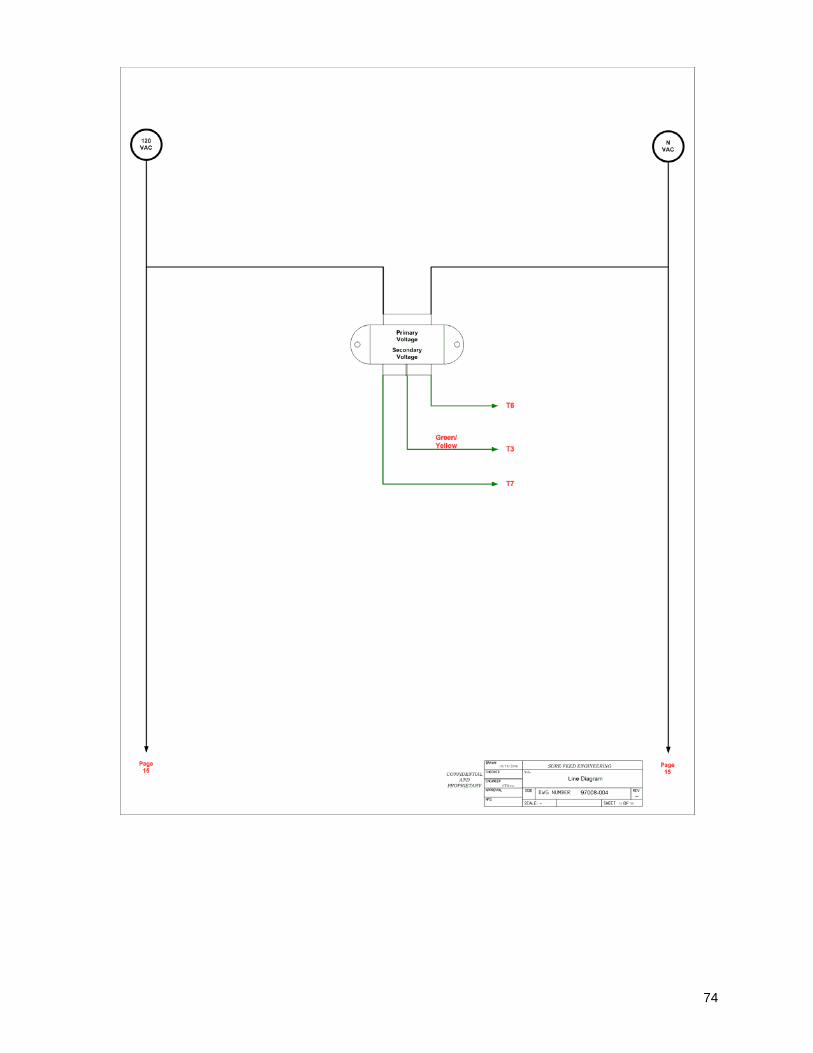
The Programmable Logic Controller, (PLC), is used only in Speed Sort Conveyor models equipped with a Pattern Reader. The PLC is located in the front leg section of the Speed Sort Conveyor.

79
SSeeccttiioonn VVII
TTrroouubblleesshhoooottiinngg

80
Speed Sort Conveyor / Stand Alone Problem Solution Will not “Power Up” Conveyor Motor is not moving
Table Belts not moving
Visually inspect the VAC power cord, making sure that the plugs are inserted firmly into wall socket. Make sure that “Twist Lock” VAC plug is twisted clockwise and locked into receptacle. Visually inspect sensor “Trigger” making sure only “GREEN” LED power indicator is lit. (GREEN indicates that the sensor is operational) After initial inspection and unit still will not run, please contact Sure Feed Engineering, Inc. For Technical Assistance
Conveyor Motor and belt continuously run
Visually Check Conveyor Sensor “Trigger” making sure Only “GREEN” LED is lit. (Both must be lit in order for machine to run. Unit needs to see material to function.) (GREEN LED indicates Power, while GREEN and ORANGE on simultaneously indicates Trigger is seeing material or obstruction) Make sure that the sensor is not seeing the conveyor or Material “Trigger Sensor” is factory set for “Depth” and “LIGHT ON” (For use with Light colored material) If adjustments need to be made please contact Sure Feed Engineering, Inc. For Technical Assistance.
Pneumatic Sorting Mechanism is not engaging
Unit is designed for Interface with other various equipment, using a “Dry Contact” type of connection. Make sure that the interface is connected (This depends upon what equipment you are interfacing to, please contact the machines manufacturer in order to find out this information.) Air pressure is required in order to operate “Sorting Function” Make sure an “Air Line” Has been attached to the Pneumatic regulator fitting, affixed to the conveyor leg. The Air control gauge has been factory set at 40psi, visually inspect gauge making sure setting is at 40psi

81
There are two air adjustment knobs on the “Sorting Adjustment Cylinder” These are factory set as well. (If adjustments need to be made, for pressure, please call Sure Feed Engineering for instructions) For further instructions, please contact Sure Feed Engineering, Inc. For Technical Assistance.
Conveyor Belt moves only at one speed
Locate Potentiometer with “Dial” and turn knob clockwise to increase speed. If no audible or visual speed variance is evident as Potentiometer is rotated, Please contact Sure Feed Engineering, Inc. For Technical Assistance.
No Delay on Conveyor Motor when material is “Not” read by sensor “Trigger” (No “Delay Time Adjustment”)
Please consult your manual for information on this function. Visually locate the “Delay Potentiometer” (without dial). Adjusting clockwise increases the delay on Conveyor Belt “Delay Time Adjustment.”
Please contact Sure Feed Engineering, Inc. For Technical Assistance.