Embed Size (px)
Citation preview
1
SPEKTRUM DX18
Programming Guide for a Six-Servo Sailplane
By: Sherman Knight July 2012 - Version 2.0 AirWare Version 1.0
The DX18 takes the best from many different radios combining them into one of the most feature laden sailplane radio to date. Some of the new sailplane features include:
Two types of V-tail setup and V-Tail differential.
Dedicated Motor Programming.
Activation of Landing Mode with the Flap Stick.
Six-servo wing programming.
Ten Flight Modes.
Telemetry for voltage, altitude and Data Logger. (more sensors coming soon)
Each trailing edge servo can be independently trimmed in each flight mode and each wing type.
For the Scale guy’s, up to 18 channels and 15 non-dedicated mixes.
Battery life in excess of 15 hours.
Two transmitter antenna fixed at 90 degrees to each other to provide antenna diversity.
Digital trim for the throttle stick so you can cross trim the elevator. The programming provided by this template and guide is for a six-servo sailplane. The pre-loaded template does all the heavy lifting. The guide then shows you how to tweak the template for your aircraft. Using the template along with sufficient time spent on the aircrafts mechanicals will result in an aircraft that is nearly ready to fly! Here is what the template includes:
Elevator and Ailerons on the right stick.
Rudder and Flaps on the left stick.
Ailerons to Rudder Mix.
Left Trimmer trims flaps together.
Right Trimmer trims ailerons together.
Five flight modes are active, Speed, Thermal, Cruise, Launch, and Land.
Four Dual rates have been preset. Speed Mode starts with the smallest rate, increasing to thermal then cruise and launch with the highest rates for Landing Mode.
Camber (trailing edge) presets have been included for each Flight Mode. Trailing edge is drooping for launch, droops less for thermal, is neutral for cruise / land and slightly up for speed.
In addition to Camber on a Flight Mode Switch, Camber adjustment on the left slider is also active. Camber is adjustable with the slider in all modes except for launch.
Pulling the flap stick below 92 % activates Landing Flight Mode. (Automatically changing rates, differential, aileron to rudder mix, flap to aileron mix, and activating the flap to elevator compensation.)
A rough Flap to Elevator compensation curve is included in landing mode.
Aileron to Flap Mix in Cruise Mode. (approximately 20%)
Differential for Aileron and Flaps for each Flight Mode.
More down elevator in Speed and Cruise Mode so you can push over at the top of a zoom.
More down elevator in Land Mode so you can push over at the spot.
As a safety feature, the radio will not turn on until you retract the flaps and turn off the launch mode.
2
The architecture of the DX18 software revolves around Flight Modes. If you want to use them all, you now have up to 10 flight modes to play with. (This guide will only activate five of them) The DX18 benefits from automatically expanding menus. The Sailplane Type you choose at the beginning of any programming determines the depths of the menus. When you select a type of sailplane, only the programming necessary for that Sailplane Type is displayed. If you select a single servo wing, many features are simply not available. Because Aileron Differential, Camber Presets or the ability to use Ailerons to double as Flaps cannot be done with just one servo, those features simply do not show up in the menu. Select two Servo wing in Sailplane Type and the menu expands to include these features. The expanding choices can also occur in other locations in the programming. If you then choose a two aileron, two flap wing, differential appears in subsequent features, but it is only available for ailerons. If, under Mixes, you elect to mix Ailerons to Flaps, a new line for flap differential appears. If AIL > FLP is active in only one Flight Mode, Flap Differential only appears under that Flight Mode. If you select a six servo wing, a new line for Tip Aileron differential appears. Pretty cool. If you are concerned about the voltage in your aircraft while it is still in the air, the DX18 provides telemetry for your sailplane. Currently, the telemetry that is of interest to sailplane pilots includes battery voltage, altitude and Data Logger information. You can see the quality of the reception for each independent receiver antenna, altitude or battery voltage in real time from your transmitter. Battery charging is built into the DX18, but it only charges at 200 mah. That means no more rapid field charging at the last minute. The up side is the battery lasts from 15 to 18 hours on a single charge! The charge port on the right side of the transmitter is not polarity-dependent. Never connect an external battery charger to your DX18 transmitter. DO YOU FLY TWO AIRPLANES AT A CONTEST? The DX18 has a feature called Direct Model Access. While the transmitter is powered up, you can go directly to Model Select by pressing the Clear and Back buttons at the same time. The DX18 offers unprecedented flexibility. Virtual mixing, any stick, slider or trim can be turned into a switch, any switch position, or combination of switches and sticks can be mixed, 10 flight modes, 15 non dedicated mixes, 18 channels, just to name a few. This flexibility allows more than one method to achieve a particular result. Because two different methods may conflict with each other, use this guide from the beginning. If you start in the middle because you have already done some programming, you will likely run into a conflict and not even know it. If a conflict occurs, it is WAY easier to start with a fresh template than to try to figure out where the problem is. A note on switches. In the digital world, an ON or OFF designation no longer exists. Instead, each position of the switch is assigned a numerical designation. A two position switch designations are 0 and 1. A three position switch designations are 0, 1 and 2. Each independent switch position can be given a different value. Mixing A to B makes a good example of how this works. If position 0 is given a value of 0, in the digital world, this results in no mixing. If position 1 is given a value of 50 and position 2 is given a value of 100, the two remaining positions will mix A to B at 50% and 100%. For those that still need an OFF switch just set the value to -0-. In addition to the switches, the DX18 also allows you to turn any Stick, trim or slider into a switch with assignable kick points. It is this flexibility that allows the Flap Stick to become a Landing Mode switch, automatically switching to Landing Mode when the Flap Stick is pulled down. All of the functions used in this guide and the template have a default value. The chosen values are at best, a rough estimate. The values have been included to make sure everything moves as soon as you load the template. The amount of movement or direction may not be correct or the direction may be backwards, but everything should move.
3
IT IS IMPORTANT TO UNERSTAND THAT YOU MUST MODIFY THESE VALUES FOR YOUR AIRCRAFT. IF YOU SPEND A LOT OF TIME ON YOUR MACHANICALS, YOU MAY ONLY NEED
SOME TWEAKING. Because Flight Modes are active, each screen may have as many as five independent Flight Mode versions. If you see a Flight Mode name on any screen, the Flight Mode can be changed by simply flipping a Flight Mode switch or pulling down on the Flap Stick. On screens where a Flight Mode name appears, all the values on that page are ONLY for that Flight Mode. The guide covers two phases. Both phases are separate but intertwined. The first phase is setting up the mechanicals of your sailplane. Pushrods, linkages, clevis, control horns and hole placement, servo horn angle and hole placement and so on. Spend time on your mechanicals. If the mechanicals are well done, the second phase, setting up your radio is much, much easier. These two phases are divided into five parts:
Part 1 is downloading and renaming the template.
Part 2 is composed primarily of the SYSTEM SETUP menu, which unless you want to change those functions, most of you will skip.
Part 3 involves setting up your mechanicals.
Part 4 is composed primarily of the FUNCTION LIST menu, which modifies the values in the radio for your particular aircraft.
Part 5 involves the final requirement before you fly for the first time. Programming the DX18 starts with two primary menus.
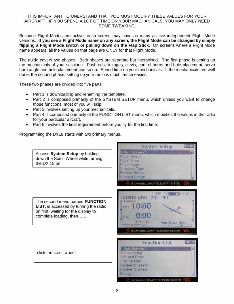
Access System Setup by holding down the Scroll Wheel while turning the DX 18 on.
The second menu named FUNCTION LIST, is accessed by turning the radio on first, waiting for the display to complete loading, then……
click the scroll wheel.
4
Navigation of the menus and sub-menus is done with the scroll wheel. Scroll the wheel to move the cursor around the screen and once over the item, push the wheel until it clicks. Scroll and click, scroll and click and scroll and click. Below each of these primary menus are sub-menus and sub-sub-menus. Turn-by-turn navigation instructions are represented throughout this guide as:
PRIMIARY MENU > SUB MENU > SUB SUB MENU > Item to be Programmed. An example would be:
FUNCTION LIST > SERVO SETUP > SUB TRIM > Select LAL (left aileron) The bold item in the turn-by-turn navigation is the name that appears at the top of the screen for the items that may need changing or just tweaking. At times, there may be several screens for a particular feature. If NEXT appears in the lower right corner there are multiple screens for the feature, click on it and you will go to the next screen. From that screen, you can back up by selecting PREV in the lower left corner. Selecting MAIN or LIST in the upper right hand corner, returns you to either the System Setup or the Function List primary screens. Navigation of a function with multiple screens is demonstrated by the following example:
SYSTEM SETUP > F-MODE SETUP > Next > Next > FLIGHT MODE TABLE This template assumes that all wing servo output gears 1) point towards the wing tip and 2) are closer to the spar. It also assumes that all wing servo arms are bottom wing and all control surface control arms are top mounted. If your setup is different, you can easily modify the template, it just takes a little more work. You may have to reverse servos, change flap SubTrim from a negative value to a positive one and change some positive values to negative and some negative to positive throughout the rest of the programming. The guide is organized in a sequence. Follow the sequence for programming the DX18 for your aircraft. This guide does not take you through all the available programming; it only uses those features that are necessary for a 6-servo sailplane. Have Fun!
Sherman Knight
What do I do if I Just Want to Play Around with the Radio, Before I Start Programming? Some of you will want to just play around with the menus until you become comfortable with it. If you do, you need to turn on all of the expanded menus discussed above or you might conclude that the DX18 is missing a bunch of stuff. Because the default Sailplane type is a single servo wing, standard tail and no motor, expanding menus only shows you what you need to see and in the default there isn’t much. So, simply tell the radio you need to see everything. In system setup select Sailplane as an aircraft type. In Sailplane type, select a six servo wing, v-tail and a motor. In The Function List, select Mixing, Select AIL > FLP and insert some values and set the switch to ON. The guide and standard template will activate some more features (such as RTrim for Flaperon trim , LTrim for Flap trim), but changing the default will get you nearly there. Remember, even if a feature is available, you must insert a value or it may not work.
5
Part 1 – The Template
STOP – BEFORE USING YOUR TRANSMITTER. Before going any further, visit the Spektrum Community website at community.spektrumrc.com
to register your transmitter and download the latest AirWare firmware updates.
DOWNLOAD THE TEMPLATE. The template is available from three sources. Kennedy Composites
http://www.kennedycomposites.com/ Soaring USA at http://www.rcgroups.com/forums/showthread.php?t=1488021&page=9#post22025757 and the Seattle Area Soaring Society. Right click on the title and click “save target as” and save the file as DX18 Sail 2AL 2FL.SPM.
TRANSFER THE SIX-SERVO TEMPLATE TO THE RADIO.
Download and transfer the file named “DX18 Sail 2AL 2FL” to an SD card. Insert the card into the slot on the bottom of the radio under the battery cover. It is recommended that the first time you turn on the system, that the servos are not installed or the linkages are disconnected, at least for the flaps. SYSTEM SETUP > TRANSFER SD CARD > SD CARD MENU
Scroll over Select Options and click. Scroll to Import Model and click. Scroll to the file named “DX18 Sail 2AL 2FL” and click. On the next screen, select IMPORT.
SELECT THE MODEL. Now that it is imported, you still have to select it.
SYSTEM SETUP > MODEL SELECT > Select “DX18 Sail 2AL 2FL”
CHANGE THE MODEL NAME. (you just imported)
SYSTEM SETUP > MODEL NAME > Select the Characters for the Name.
The model name can be up to 20 characters long.
Recommendation: Copy (Model Copy) the template to a second available model memory so you may copy this standard template for use in the future.
COPY THE DX18 SIX SERVO SAILPLANE TEMPLATE TO ANOTHER MODEL.
SYSTEM SETUP > MODEL COPY >
Use “Select the Model” to select the model you want to copy. This feature copies the model that is currently loaded into the DX18 to a new model.
Use “Model Copy” to copy the current model to a new model.
Highlight the box after “To” and select the name for the new model.
Click copy.
DO YOU FLY TWO AIRPLANES AT A CONTEST? The DX18 has a feature called Direct Model
Access. While the transmitter is powered on, you can go directly to Model Select by pressing the Clear and Back buttons at the same time.
6
Part 2 – System Setup
The SYSTEM SETUP portion of the guide may not need any modification if you have a six-servo sailplane. If the default setting are acceptable, you may move directly to Part Three.
CHANGING NUMBER OF WING SERVOS, V OR CROSS TAIL, AND MOTOR.
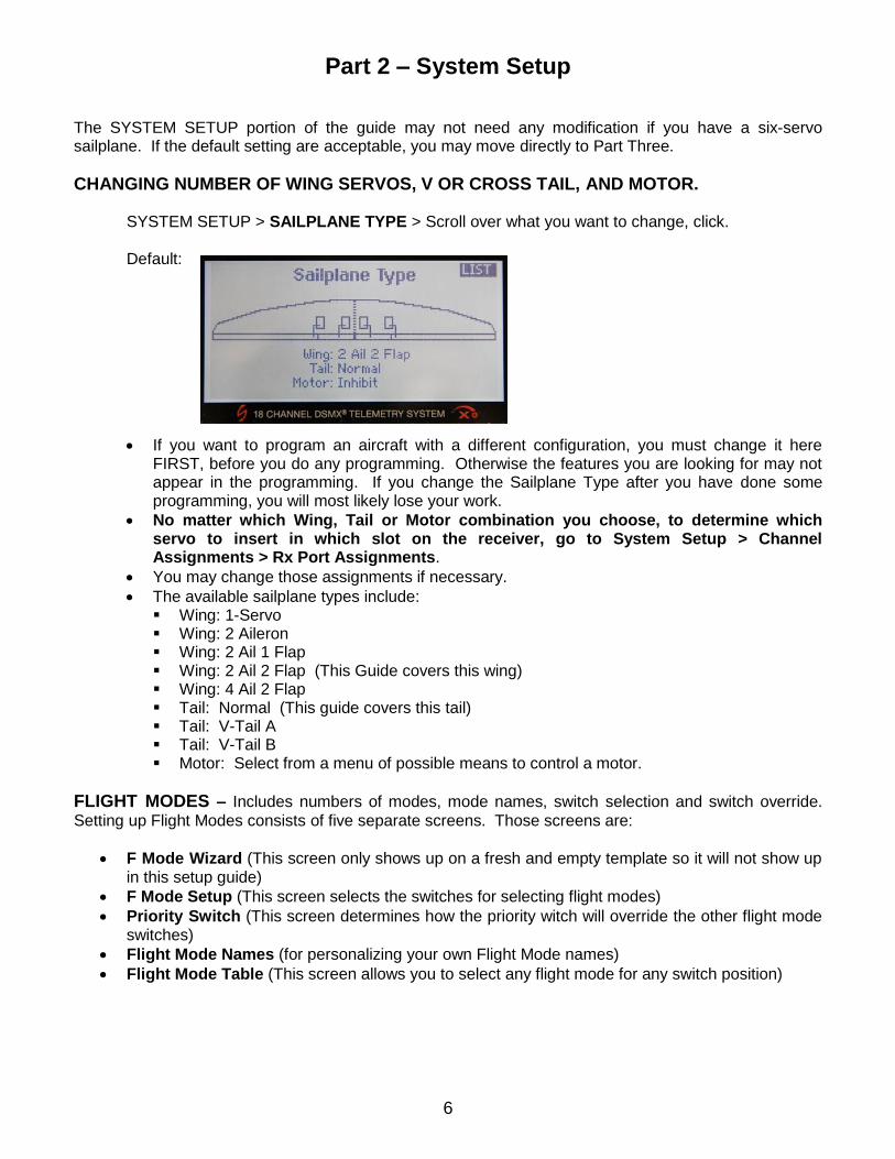
SYSTEM SETUP > SAILPLANE TYPE > Scroll over what you want to change, click. Default:
If you want to program an aircraft with a different configuration, you must change it here FIRST, before you do any programming. Otherwise the features you are looking for may not appear in the programming. If you change the Sailplane Type after you have done some programming, you will most likely lose your work.
No matter which Wing, Tail or Motor combination you choose, to determine which servo to insert in which slot on the receiver, go to System Setup > Channel Assignments > Rx Port Assignments.
You may change those assignments if necessary.
The available sailplane types include: Wing: 1-Servo Wing: 2 Aileron Wing: 2 Ail 1 Flap Wing: 2 Ail 2 Flap (This Guide covers this wing) Wing: 4 Ail 2 Flap Tail: Normal (This guide covers this tail) Tail: V-Tail A Tail: V-Tail B Motor: Select from a menu of possible means to control a motor.
FLIGHT MODES – Includes numbers of modes, mode names, switch selection and switch override.
Setting up Flight Modes consists of five separate screens. Those screens are:
F Mode Wizard (This screen only shows up on a fresh and empty template so it will not show up in this setup guide)
F Mode Setup (This screen selects the switches for selecting flight modes)
Priority Switch (This screen determines how the priority witch will override the other flight mode switches)
Flight Mode Names (for personalizing your own Flight Mode names)
Flight Mode Table (This screen allows you to select any flight mode for any switch position)
7
SELECTING FLIGHT MODE SWITCHES
SYSTEM SETUP > F-MODE SETUP > FLIGHT MODE SETUP Default:
The Flight Mode Switches are switch B and C.
Priority Switch: Throttle Stick.
Comments:
This screen selects the switches that activate the different Flight Modes. You can change the switches by scrolling over them, click, and then scroll again to select from a list. Each switch is identified on the face of the radio.
This screen also selects whether or not you want a switch or stick to override all other flight modes with a specific “priority switch.” This template selects “throttle stick” so that when you pull the flaps stick down it automatically selects Landing Mode. To disable the flap stick switching to the Landing Mode automatically, change Throttle Stick to Inhibit.
Activate all 10 Flight Modes by assigning a switch to Switch 3.
PRIORITY SWITCH
SYSTEM SETUP > F-MODE SETUP > FLIGHT MODE SETUP > Next > PRIORITY SWITCH Default:
Pos 0: Switches
Pos 1: Land
Pos 2: Land
Comments:
This screen is one of two screens that add a switch to the Flap Stick, activating Landing Mode by pulling down the Flap Stick.
Analog Switch Setup (the second screen, see below) creates a “kick point” switch position anywhere along the arc of the Flap Stick travel. In this case the kick point is at 92% of Flap Stick Travel.
If the Flap Stick is greater than 92%, (position 0), this screen instructs the DX18 to use the switches to determining the current flight mode. If the Flap Stick position is less than 92%, (position 1 & 2) this screen instructs the radio to change the current Flight Mode to Landing Mode, overriding the Flight Mode Switches.
8
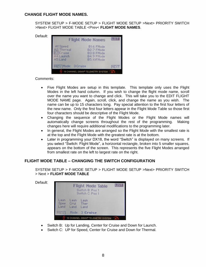
CHANGE FLIGHT MODE NAMES.
SYSTEM SETUP > F-MODE SETUP > FLIGHT MODE SETUP >Next> PRIORITY SWITCH >Next> FLIGHT MODE TABLE <Prev< FLIGHT MODE NAMES.
Default:
Comments:
Five Flight Modes are setup in this template. This template only uses the Flight Modes in the left hand column. If you wish to change the flight mode name, scroll over the name you want to change and click. This will take you to the EDIT FLIGHT MODE NAME page. Again, scroll, click, and change the name as you wish. The name can be up to 15 characters long. Pay special attention to the first four letters of the new name. Only the first four letters appear in the Flight Mode Table so those first four characters should be descriptive of the Flight Mode.
Changing the sequence of the Flight Modes or the Flight Mode names will automatically change screens throughout the rest of the programming. Making changes here will require additional modifications to the programming later.
In general, the Flight Modes are arranged so the Flight Mode with the smallest rate is at the top and the Flight Mode with the greatest rate is at the bottom.
Later in programming your DX18, the word “Switch” is displayed on many screens. If you select “Switch: Flight Mode”, a horizontal rectangle, broken into 5 smaller squares, appears on the bottom of the screen. This represents the five Flight Modes arranged from smallest rate on the left to largest rate on the right.
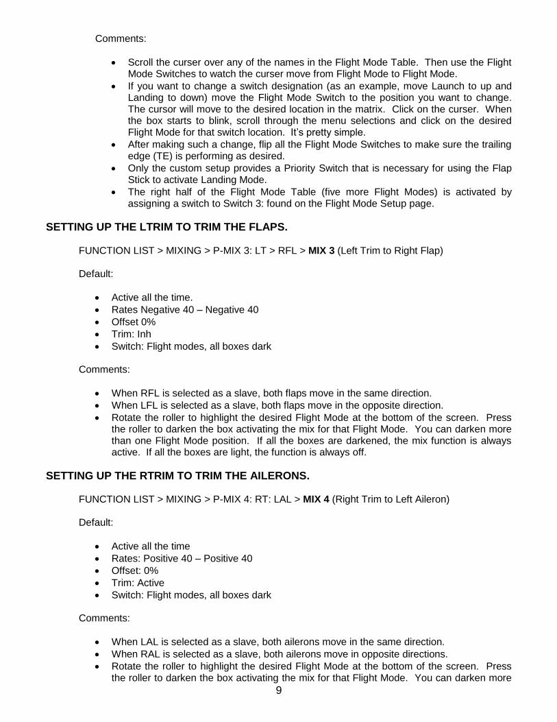
FLIGHT MODE TABLE – CHANGING THE SWITCH CONFIGURATION
SYSTEM SETUP > F-MODE SETUP > FLIGHT MODE SETUP >Next> PRIORITY SWITCH > Next > FLIGHT MODE TABLE
Default:
Switch B: Up for Landing, Center for Cruise and Down for Launch.
Switch C: UP for Speed, Center for Cruise and Down for Thermal.
9
Comments:
Scroll the curser over any of the names in the Flight Mode Table. Then use the Flight Mode Switches to watch the curser move from Flight Mode to Flight Mode.
If you want to change a switch designation (as an example, move Launch to up and Landing to down) move the Flight Mode Switch to the position you want to change. The cursor will move to the desired location in the matrix. Click on the curser. When the box starts to blink, scroll through the menu selections and click on the desired Flight Mode for that switch location. It’s pretty simple.
After making such a change, flip all the Flight Mode Switches to make sure the trailing edge (TE) is performing as desired.
Only the custom setup provides a Priority Switch that is necessary for using the Flap Stick to activate Landing Mode.
The right half of the Flight Mode Table (five more Flight Modes) is activated by assigning a switch to Switch 3: found on the Flight Mode Setup page.
SETTING UP THE LTRIM TO TRIM THE FLAPS.
FUNCTION LIST > MIXING > P-MIX 3: LT > RFL > MIX 3 (Left Trim to Right Flap) Default:
Active all the time.
Rates Negative 40 – Negative 40
Offset 0%
Trim: Inh
Switch: Flight modes, all boxes dark Comments:
When RFL is selected as a slave, both flaps move in the same direction.
When LFL is selected as a slave, both flaps move in the opposite direction.
Rotate the roller to highlight the desired Flight Mode at the bottom of the screen. Press the roller to darken the box activating the mix for that Flight Mode. You can darken more than one Flight Mode position. If all the boxes are darkened, the mix function is always active. If all the boxes are light, the function is always off.
SETTING UP THE RTRIM TO TRIM THE AILERONS.
FUNCTION LIST > MIXING > P-MIX 4: RT: LAL > MIX 4 (Right Trim to Left Aileron) Default:
Active all the time
Rates: Positive 40 – Positive 40
Offset: 0%
Trim: Active
Switch: Flight modes, all boxes dark Comments:
When LAL is selected as a slave, both ailerons move in the same direction.
When RAL is selected as a slave, both ailerons move in opposite directions.
Rotate the roller to highlight the desired Flight Mode at the bottom of the screen. Press the roller to darken the box activating the mix for that Flight Mode. You can darken more
10
than one Flight Mode position. If all the boxes are darkened, the mix function is always active. If all the boxes are light, the function is always off.
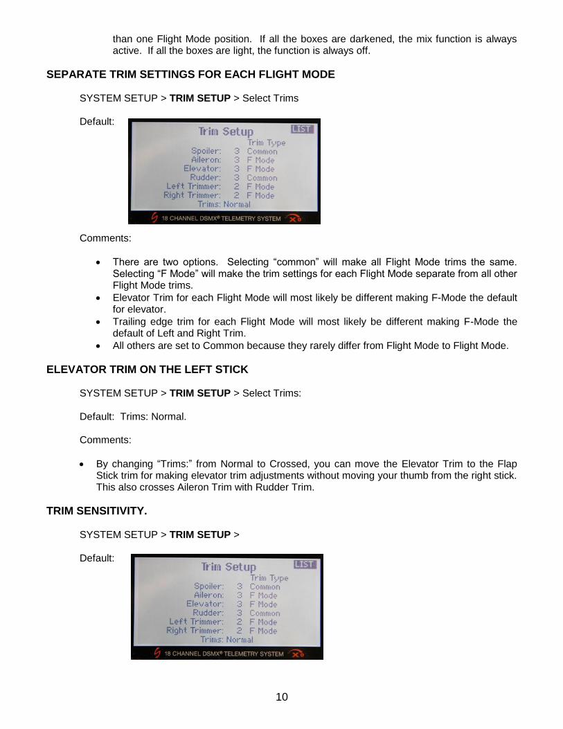
SEPARATE TRIM SETTINGS FOR EACH FLIGHT MODE
SYSTEM SETUP > TRIM SETUP > Select Trims Default: Comments:
There are two options. Selecting “common” will make all Flight Mode trims the same. Selecting “F Mode” will make the trim settings for each Flight Mode separate from all other Flight Mode trims.
Elevator Trim for each Flight Mode will most likely be different making F-Mode the default for elevator.
Trailing edge trim for each Flight Mode will most likely be different making F-Mode the default of Left and Right Trim.
All others are set to Common because they rarely differ from Flight Mode to Flight Mode.
ELEVATOR TRIM ON THE LEFT STICK
SYSTEM SETUP > TRIM SETUP > Select Trims: Default: Trims: Normal.
Comments:
By changing “Trims:” from Normal to Crossed, you can move the Elevator Trim to the Flap Stick trim for making elevator trim adjustments without moving your thumb from the right stick. This also crosses Aileron Trim with Rudder Trim.
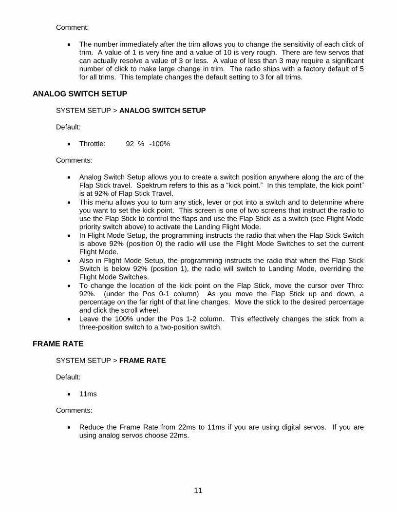
TRIM SENSITIVITY.
SYSTEM SETUP > TRIM SETUP >
Default:
11
Comment:
The number immediately after the trim allows you to change the sensitivity of each click of trim. A value of 1 is very fine and a value of 10 is very rough. There are few servos that can actually resolve a value of 3 or less. A value of less than 3 may require a significant number of click to make large change in trim. The radio ships with a factory default of 5 for all trims. This template changes the default setting to 3 for all trims.
ANALOG SWITCH SETUP
SYSTEM SETUP > ANALOG SWITCH SETUP Default:
Throttle: 92 % -100%
Comments:
Analog Switch Setup allows you to create a switch position anywhere along the arc of the Flap Stick travel. Spektrum refers to this as a “kick point.” In this template, the kick point” is at 92% of Flap Stick Travel.
This menu allows you to turn any stick, lever or pot into a switch and to determine where you want to set the kick point. This screen is one of two screens that instruct the radio to use the Flap Stick to control the flaps and use the Flap Stick as a switch (see Flight Mode priority switch above) to activate the Landing Flight Mode.
In Flight Mode Setup, the programming instructs the radio that when the Flap Stick Switch is above 92% (position 0) the radio will use the Flight Mode Switches to set the current Flight Mode.
Also in Flight Mode Setup, the programming instructs the radio that when the Flap Stick Switch is below 92% (position 1), the radio will switch to Landing Mode, overriding the Flight Mode Switches.
To change the location of the kick point on the Flap Stick, move the cursor over Thro: 92%. (under the Pos 0-1 column) As you move the Flap Stick up and down, a percentage on the far right of that line changes. Move the stick to the desired percentage and click the scroll wheel.
Leave the 100% under the Pos 1-2 column. This effectively changes the stick from a three-position switch to a two-position switch.
FRAME RATE
SYSTEM SETUP > FRAME RATE Default:
11ms
Comments:
Reduce the Frame Rate from 22ms to 11ms if you are using digital servos. If you are using analog servos choose 22ms.

12
WARNINGS SYSTEM SETUP > WARNINGS. Default: If the radio is set to Launch Mode or Landing Mode by switch or Landing Mode by Flap Stick, the radio will not turn on and a display will be shown. You will be directed to take the radio out of Launch or Land Mode before the radio will start.
To defeat these warnings, on the Warnings page, highlight Flight Modes 4 and 5 and click until the box changes from dark to light.
DEFAULT SOUNDS AND ALARMS SYSTEM SETUP > SYSTEM SETTINGS > Next > Extra Settings
Default: System Sounds: Inhibit (this turns off the beep that occurs at every push of the scroll wheel.
Vibrator: Active
13
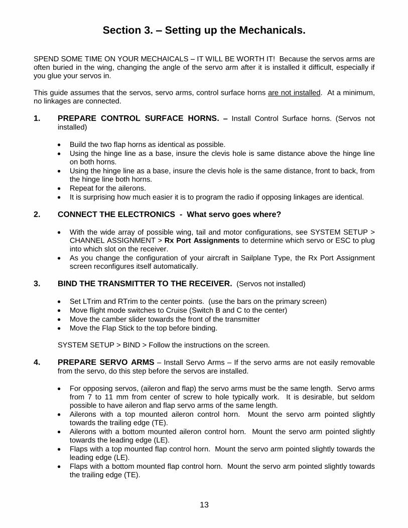
Section 3. – Setting up the Mechanicals. SPEND SOME TIME ON YOUR MECHAICALS – IT WILL BE WORTH IT! Because the servos arms are often buried in the wing, changing the angle of the servo arm after it is installed it difficult, especially if you glue your servos in. This guide assumes that the servos, servo arms, control surface horns are not installed. At a minimum, no linkages are connected.
1. PREPARE CONTROL SURFACE HORNS. – Install Control Surface horns. (Servos not
installed)
Build the two flap horns as identical as possible.
Using the hinge line as a base, insure the clevis hole is same distance above the hinge line on both horns.
Using the hinge line as a base, insure the clevis hole is the same distance, front to back, from the hinge line both horns.
Repeat for the ailerons.
It is surprising how much easier it is to program the radio if opposing linkages are identical.
2. CONNECT THE ELECTRONICS - What servo goes where?
With the wide array of possible wing, tail and motor configurations, see SYSTEM SETUP > CHANNEL ASSIGNMENT > Rx Port Assignments to determine which servo or ESC to plug into which slot on the receiver.
As you change the configuration of your aircraft in Sailplane Type, the Rx Port Assignment screen reconfigures itself automatically.
3. BIND THE TRANSMITTER TO THE RECEIVER. (Servos not installed)
Set LTrim and RTrim to the center points. (use the bars on the primary screen)
Move flight mode switches to Cruise (Switch B and C to the center)
Move the camber slider towards the front of the transmitter
Move the Flap Stick to the top before binding.
SYSTEM SETUP > BIND > Follow the instructions on the screen.
4. PREPARE SERVO ARMS – Install Servo Arms – If the servo arms are not easily removable
from the servo, do this step before the servos are installed.
For opposing servos, (aileron and flap) the servo arms must be the same length. Servo arms from 7 to 11 mm from center of screw to hole typically work. It is desirable, but seldom possible to have aileron and flap servo arms of the same length.
Ailerons with a top mounted aileron control horn. Mount the servo arm pointed slightly towards the trailing edge (TE).
Ailerons with a bottom mounted aileron control horn. Mount the servo arm pointed slightly towards the leading edge (LE).
Flaps with a top mounted flap control horn. Mount the servo arm pointed slightly towards the leading edge (LE).
Flaps with a bottom mounted flap control horn. Mount the servo arm pointed slightly towards the trailing edge (TE).
14
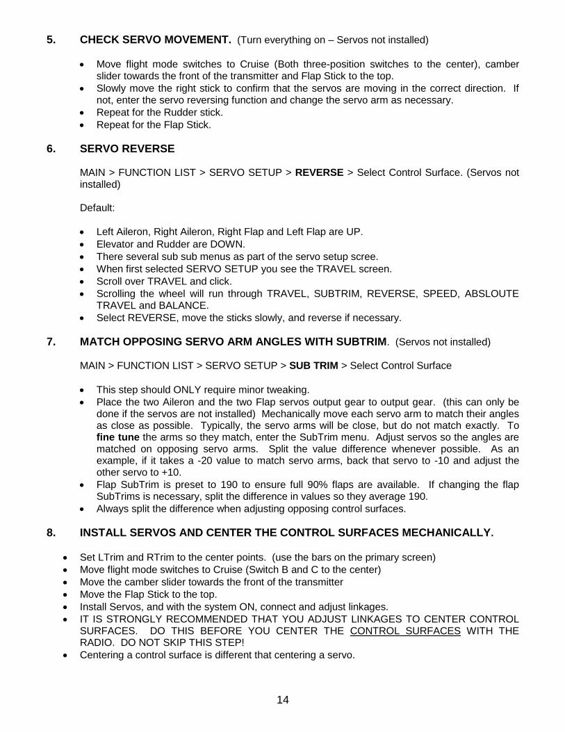
5. CHECK SERVO MOVEMENT. (Turn everything on – Servos not installed)
Move flight mode switches to Cruise (Both three-position switches to the center), camber slider towards the front of the transmitter and Flap Stick to the top.
Slowly move the right stick to confirm that the servos are moving in the correct direction. If not, enter the servo reversing function and change the servo arm as necessary.
Repeat for the Rudder stick.
Repeat for the Flap Stick.
6. SERVO REVERSE
MAIN > FUNCTION LIST > SERVO SETUP > REVERSE > Select Control Surface. (Servos not installed) Default:
Left Aileron, Right Aileron, Right Flap and Left Flap are UP.
Elevator and Rudder are DOWN.
There several sub sub menus as part of the servo setup scree.
When first selected SERVO SETUP you see the TRAVEL screen.
Scroll over TRAVEL and click.
Scrolling the wheel will run through TRAVEL, SUBTRIM, REVERSE, SPEED, ABSLOUTE TRAVEL and BALANCE.
Select REVERSE, move the sticks slowly, and reverse if necessary.
7. MATCH OPPOSING SERVO ARM ANGLES WITH SUBTRIM. (Servos not installed)
MAIN > FUNCTION LIST > SERVO SETUP > SUB TRIM > Select Control Surface
This step should ONLY require minor tweaking.
Place the two Aileron and the two Flap servos output gear to output gear. (this can only be done if the servos are not installed) Mechanically move each servo arm to match their angles as close as possible. Typically, the servo arms will be close, but do not match exactly. To fine tune the arms so they match, enter the SubTrim menu. Adjust servos so the angles are matched on opposing servo arms. Split the value difference whenever possible. As an example, if it takes a -20 value to match servo arms, back that servo to -10 and adjust the other servo to +10.
Flap SubTrim is preset to 190 to ensure full 90% flaps are available. If changing the flap SubTrims is necessary, split the difference in values so they average 190.
Always split the difference when adjusting opposing control surfaces.
8. INSTALL SERVOS AND CENTER THE CONTROL SURFACES MECHANICALLY.
Set LTrim and RTrim to the center points. (use the bars on the primary screen)
Move flight mode switches to Cruise (Switch B and C to the center)
Move the camber slider towards the front of the transmitter
Move the Flap Stick to the top.
Install Servos, and with the system ON, connect and adjust linkages.
IT IS STRONGLY RECOMMENDED THAT YOU ADJUST LINKAGES TO CENTER CONTROL SURFACES. DO THIS BEFORE YOU CENTER THE CONTROL SURFACES WITH THE RADIO. DO NOT SKIP THIS STEP!
Centering a control surface is different that centering a servo.
15
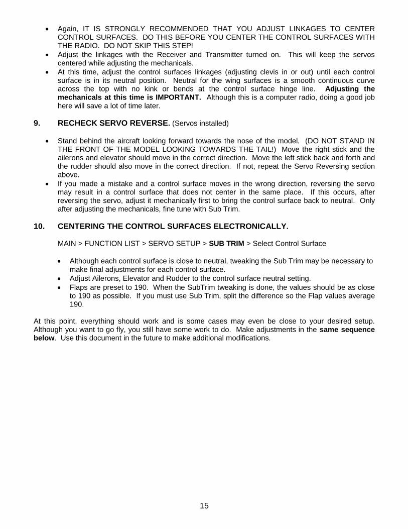
Again, IT IS STRONGLY RECOMMENDED THAT YOU ADJUST LINKAGES TO CENTER CONTROL SURFACES. DO THIS BEFORE YOU CENTER THE CONTROL SURFACES WITH THE RADIO. DO NOT SKIP THIS STEP!
Adjust the linkages with the Receiver and Transmitter turned on. This will keep the servos centered while adjusting the mechanicals.
At this time, adjust the control surfaces linkages (adjusting clevis in or out) until each control surface is in its neutral position. Neutral for the wing surfaces is a smooth continuous curve across the top with no kink or bends at the control surface hinge line. Adjusting the mechanicals at this time is IMPORTANT. Although this is a computer radio, doing a good job here will save a lot of time later.
9. RECHECK SERVO REVERSE. (Servos installed)
Stand behind the aircraft looking forward towards the nose of the model. (DO NOT STAND IN THE FRONT OF THE MODEL LOOKING TOWARDS THE TAIL!) Move the right stick and the ailerons and elevator should move in the correct direction. Move the left stick back and forth and the rudder should also move in the correct direction. If not, repeat the Servo Reversing section above.
If you made a mistake and a control surface moves in the wrong direction, reversing the servo may result in a control surface that does not center in the same place. If this occurs, after reversing the servo, adjust it mechanically first to bring the control surface back to neutral. Only after adjusting the mechanicals, fine tune with Sub Trim.
10. CENTERING THE CONTROL SURFACES ELECTRONICALLY.
MAIN > FUNCTION LIST > SERVO SETUP > SUB TRIM > Select Control Surface
Although each control surface is close to neutral, tweaking the Sub Trim may be necessary to make final adjustments for each control surface.
Adjust Ailerons, Elevator and Rudder to the control surface neutral setting.
Flaps are preset to 190. When the SubTrim tweaking is done, the values should be as close to 190 as possible. If you must use Sub Trim, split the difference so the Flap values average 190.
At this point, everything should work and is some cases may even be close to your desired setup. Although you want to go fly, you still have some work to do. Make adjustments in the same sequence below. Use this document in the future to make additional modifications.
16
Part 4 – Programming the Model
At this point, if the mechanicals were well done, there is a chance that the aircraft is in a flyable condition with just a few tweaks. As stated earlier, the default settings are just a ballpark value. Different styles of flying (twitchy vs. slow setups etc.) and differences in aircraft design, (this is a very long list) require the modification of the values in several areas. This section shows you how to modify those values. Always check the current Flight Mode before you start changing values. It is easy to mistakenly be in a different Flight Mode than you think. Especially, if you inadvertently bump the Flap Stick. As stated earlier, it is recommended that you program in the same sequence below.
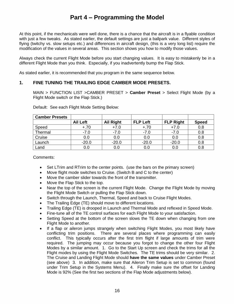
1. FINE TUNING THE TRAILING EDGE CAMBER MODE PRESETS.
MAIN > FUNCTION LIST >CAMBER PRESET > Camber Preset > Select Flight Mode (by a Flight Mode switch or the Flap Stick.) Default: See each Flight Mode Setting Below:
Camber Presets
Ail Left Ail Right FLP Left FLP Right Speed
Speed +.70 +7.0 +.70 +7.0 0.8
Thermal -7.0 -7.0 -7.0 -7.0 0.8
Cruise 0.0 0.0 0.0 0.0 0.8
Launch -20.0 -20.0 -20.0 -20.0 0.8
Land 0.0 0.0 0.0 0.0 0.8
Comments:
Set LTrim and RTrim to the center points. (use the bars on the primary screen)
Move flight mode switches to Cruise. (Switch B and C to the center)
Move the camber slider towards the front of the transmitter.
Move the Flap Stick to the top.
Near the top of the screen is the current Flight Mode. Change the Flight Mode by moving the Flight Mode Switch or pulling the Flap Stick down.
Switch through the Launch, Thermal, Speed and back to Cruise Flight Modes.
The Trailing Edge (TE) should move to different locations.
Trailing Edge (TE) is drooped in Launch and Thermal Mode and reflexed in Speed Mode.
Fine-tune all of the TE control surfaces for each Flight Mode to your satisfaction.
Setting Speed at the bottom of the screen slows the TE down when changing from one Flight Mode to another.
If a flap or aileron jumps strangely when switching Flight Modes, you most likely have conflicting trim positions. There are several places where programming can easily conflict. This typically occurs after the first trim flight if large amounts of trim were required. The jumping may occur because you forgot to change the other four Flight Modes by a similar amount. 1. Go to the Start Up screen and check the trims for all the Flight modes by using the Flight Mode Switches. The TE trims should be very similar. 2. The Cruise and Landing Flight Mode should have the same values under Camber Preset (see above) 3. In addition, make sure that Aileron Trim Setup is set to common (found under Trim Setup in the Systems Menu). 4. Finally make sure the offset for Landing Mode is 92% (See the first two sections of the Flap Mode adjustments below).
17
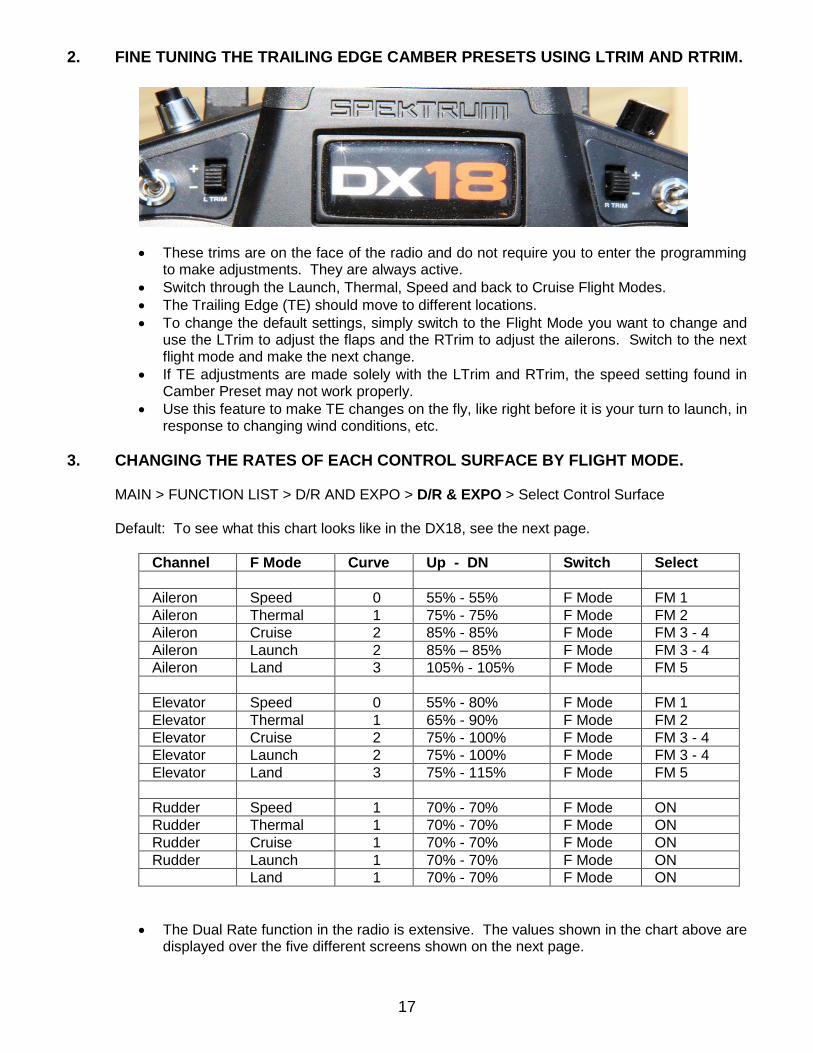
2. FINE TUNING THE TRAILING EDGE CAMBER PRESETS USING LTRIM AND RTRIM.
These trims are on the face of the radio and do not require you to enter the programming to make adjustments. They are always active.
Switch through the Launch, Thermal, Speed and back to Cruise Flight Modes.
The Trailing Edge (TE) should move to different locations.
To change the default settings, simply switch to the Flight Mode you want to change and use the LTrim to adjust the flaps and the RTrim to adjust the ailerons. Switch to the next flight mode and make the next change.
If TE adjustments are made solely with the LTrim and RTrim, the speed setting found in Camber Preset may not work properly.
Use this feature to make TE changes on the fly, like right before it is your turn to launch, in response to changing wind conditions, etc.
3. CHANGING THE RATES OF EACH CONTROL SURFACE BY FLIGHT MODE.
MAIN > FUNCTION LIST > D/R AND EXPO > D/R & EXPO > Select Control Surface Default: To see what this chart looks like in the DX18, see the next page.
Channel F Mode Curve Up - DN Switch Select
Aileron Speed 0 55% - 55% F Mode FM 1
Aileron Thermal 1 75% - 75% F Mode FM 2
Aileron Cruise 2 85% - 85% F Mode FM 3 - 4
Aileron Launch 2 85% – 85% F Mode FM 3 - 4
Aileron Land 3 105% - 105% F Mode FM 5
Elevator Speed 0 55% - 80% F Mode FM 1
Elevator Thermal 1 65% - 90% F Mode FM 2
Elevator Cruise 2 75% - 100% F Mode FM 3 - 4
Elevator Launch 2 75% - 100% F Mode FM 3 - 4
Elevator Land 3 75% - 115% F Mode FM 5
Rudder Speed 1 70% - 70% F Mode ON
Rudder Thermal 1 70% - 70% F Mode ON
Rudder Cruise 1 70% - 70% F Mode ON
Rudder Launch 1 70% - 70% F Mode ON
Land 1 70% - 70% F Mode ON
The Dual Rate function in the radio is extensive. The values shown in the chart above are displayed over the five different screens shown on the next page.
18
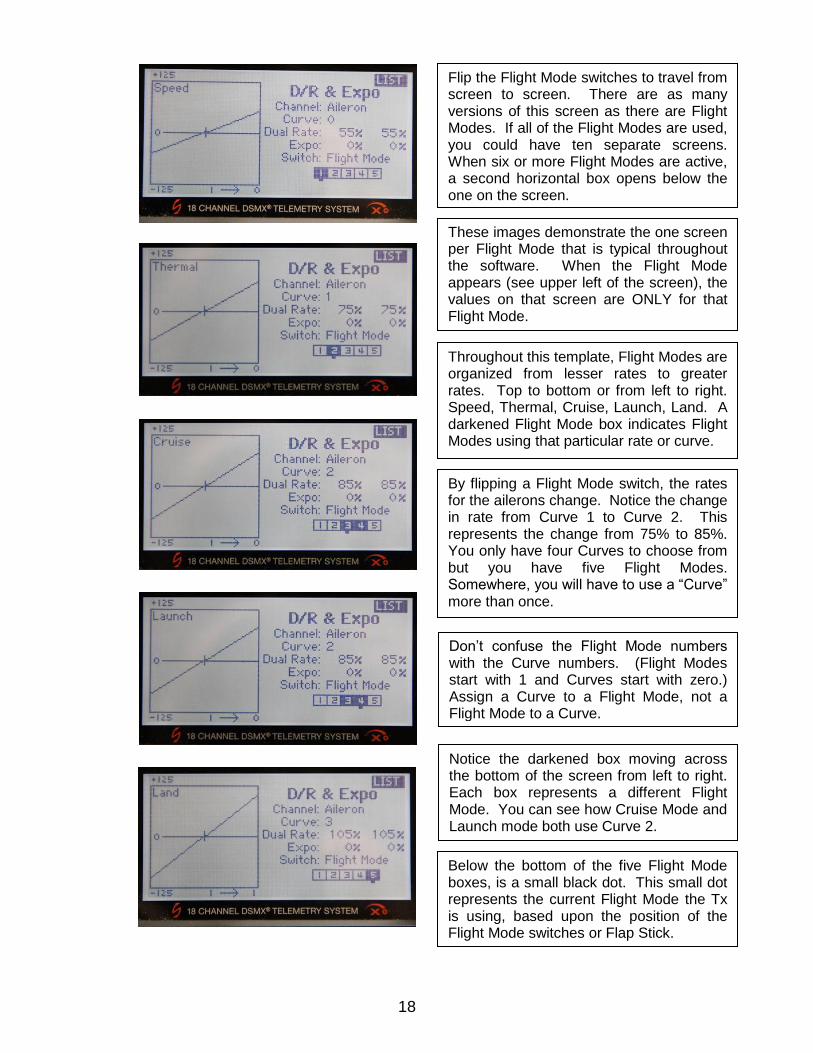
By flipping a Flight Mode switch, the rates for the ailerons change. Notice the change in rate from Curve 1 to Curve 2. This represents the change from 75% to 85%. You only have four Curves to choose from but you have five Flight Modes. Somewhere, you will have to use a “Curve” more than once.
These images demonstrate the one screen per Flight Mode that is typical throughout the software. When the Flight Mode appears (see upper left of the screen), the values on that screen are ONLY for that Flight Mode.
Notice the darkened box moving across the bottom of the screen from left to right. Each box represents a different Flight Mode. You can see how Cruise Mode and Launch mode both use Curve 2.
Throughout this template, Flight Modes are organized from lesser rates to greater rates. Top to bottom or from left to right. Speed, Thermal, Cruise, Launch, Land. A darkened Flight Mode box indicates Flight Modes using that particular rate or curve.
Below the bottom of the five Flight Mode boxes, is a small black dot. This small dot represents the current Flight Mode the Tx is using, based upon the position of the Flight Mode switches or Flap Stick.
Flip the Flight Mode switches to travel from screen to screen. There are as many versions of this screen as there are Flight Modes. If all of the Flight Modes are used, you could have ten separate screens. When six or more Flight Modes are active, a second horizontal box opens below the one on the screen.
Don’t confuse the Flight Mode numbers with the Curve numbers. (Flight Modes start with 1 and Curves start with zero.) Assign a Curve to a Flight Mode, not a Flight Mode to a Curve.
19
Comments:
Recommendation: Spend your first couple of flights focused on trimming Cruise Mode. Only after you are comfortable in Cruise mode, land and change the rates for Aileron and Elevator. Start with difference similar to what is set in the table. If you reduce a value in Cruise by 20%, reduce all the other curves by the same amount. You now have a base from which to continue trimming your aircraft.
In general, this template has been preset with the least amount of rate, Speed Mode assigned to the box on the left ascending to the box on the right with the greatest rate (Landing Mode).
Curve is a fancy way of saying “rates.” You can choose one of four different Curves consisting of a rate between 0 to 100 combined with an exponential rate between a negative 100 and a positive 100.
The curves are already built for each Flight Mode. Scroll to the control surface you want to modify (Aileron, Elevator or Rudder), make sure you are in the correct Flight Mode (by using the flight mode switches) and change the values as necessary.
You can change which “curve” is assigned to each Flight Mode. Under Flight Mode, scroll the cursor over the appropriate Flight Mode and push the roller to darken the box. This curve is now active for this Flight Mode. You can darken more than one Flight Mode position. If all the boxes are darkened, the mix function is always active. If all the boxes are light, the function is always off.
4. EXTRA DOWN ELEVATOR TO HELP PUSHOVER AT THE TOP OF THE ZOOM. MAIN > FUNCTION LIST > DR AND EXPO > D/R & EXPO > Select Elevator Default:
Channel F Mode Curve UP - DN Switch Select
Elevator Speed 0 55% - 80% F Mode FM 1
Elevator Thermal 1 65% - 90% F Mode FM 2
Elevator Cruise 2 75% - 100% F Mode FM 3 - 4
Elevator Launch 2 70% - 95% F Mode FM 3 - 4
Elevator Land 3 75% - 115% F Mode FM 5
On the above table under Flight Modes, there is a rate difference between up and down. In these flight modes, there is more down Elevator than up.
Scroll the cursor over Dual Rate: and Click. Surrounding the values is a blinking rectangular box. Push the Elevator Stick forward and change the value in that box.
5. SETTING THE AILERON DIFFERENTIAL BY FLIGHT MODE.
MAIN > FUNCTION LIST > DIFFERENTIAL > Differential > Select Flight Mode Default:
Flight Mode 1 – Speed: 40%.
Flight Mode 2 – Thermal: 70%.
Flight Mode 3 – Cruise: 60%.
Flight Mode 4 – Launch: 90%
Flight Mode 5 – Landing: 60%.
20
Comments:
Differential creates more up aileron than down. The default Cruise is approximately 60%. The default for speed is less and the default for Launch and Land is more.
By flipping the Flight Mode switches or moving the flap stick, the flight modes on the screen change. You can adjust the Differential for the ailerons in each of the Flight Modes.
Recommendation: Set the Differential for Cruise first. Once established, Change the other Flight modes by the same amount. You now have a base to continue trimming your aircraft.
Very little down aileron is necessary in Launch mode.
If AIL > FLP is active in Mixing, (This mix is activated in this template) a second row for Flap differential appears.
If you selected 4 Ailerons and 2 Flaps in System Setup, a third row will appear for Tip Aileron Differential.
6. MAKE THE AILERONS THE SAME USING TRAVEL ADJUSTMENTS. MAIN > FUNCTION LIST > SERVO SETUP > Select Travel. Comments:
There are very few situations where you will need to use Travel Adjustments.
Select Cruise Mode.
Move the Aileron Stick to the stop on one side and measure the up and down throw on one side. Move the Aileron Stick to the opposite side and measure the other aileron up and down throw.
Using the Travel Adjustment for Left Aileron (LAL) and Right Aileron (RAL) make adjustments so that the up and down throw on each side is the same.
Recommendation: Reduce the aileron with the greatest throw, then split the difference. (ie, if one side is reduced 20% to make the movement the same, cut back that aileron to 10% and increase the other by 10%)
7. AILERON > RUDDER MIX.
MAIN > FUNCTION LIST > MIXING > “AIL > RUD” > Aileron > Rudder Default:
Flight Mode 1 – Speed: 25%.
Flight Mode 2 – Thermal: 75%.
Flight Mode 3 – Cruise: 60%.
Flight Mode 4 – Launch: 80%
Flight Mode 5 – Landing: 75%.
Switch is set to flight mode.
Comments:
The proper balance between Differential, AIL > RUD mix and speed of the aircraft will provide well balanced turns.
A different percentage of mix is available for each Flight Mode.
The current flight mode is reflected near the top of the screen and is changed by moving the Flight Mode Switch(s).
ALL the adjustments on the screen are only for that Flight Mode.
21
To reduce yaw in Speed Mode, the mix is small.
To increase yaw in Thermal Mode (flatter turns), the mix is medium.
To help balance a turn at Cruising and Landing Mode, the mix is medium.
To maximize yaw (and reduce roll) In Launch Mode, the mix is very high.
8. AILERON > FLAP MIX.
MAIN > FUNCTION LIST > MIXING > “AIL > FLP” > Aileron > Flaps Default: Left Right
Flight Mode 1 – Speed: 0%. 0%
Flight Mode 2 – Thermal: 0%. 0%
Flight Mode 3 – Cruise: 30%. 30%
Flight Mode 4 – Launch: 0% 0%
Flight Mode 5 – Landing: 0%. 0%
Switch is set to flight mode.
Comments:
A different percentage of mix is available for each Flight Mode.
The current flight mode is reflected near the top of the screen and is changed by moving the Flight Mode Switch(s).
ALL the adjustments on the screen are only for that Flight Mode.
To reduce aileron (roll) rate in Speed Roll, the mix is off.
To provide the greatest lift in Thermal Mode, the mix is off.
To increase aileron (roll) rate in Cruise Mode, the mix is on.
To maintain lift in Launch Mode, the mix is off.
To maintain breaking and to keep flaps from binding in Landing Mode, the mix should be off.
If a value is provided for AIL > FLP, Differential for the Flaps is then available in Differential.
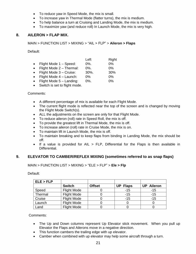
9. ELEVATOR TO CAMBER/REFLEX MIXING (sometimes referred to as snap flaps)
MAIN > FUNCTION LIST > MIXING > “ELE > FLP” > Ele > Flp Default:
ELE > FLP
Switch Offset UP Flaps UP Aileron
Speed Flight Mode 0 -15 -15
Thermal Flight Mode 0 -15 -15
Cruise Flight Mode 0 -15 -15
Launch Flight Mode 0 0 0
Land Flight Mode 0 0 0
Comments:
The Up and Down columns represent Up Elevator stick movement. When you pull up Elevator the Flaps and Ailerons move in a negative direction.
This function cambers the trailing edge with up elevator.
Camber when combined with up elevator may help some aircraft through a turn.
22
Camber (or Reflex) does not “snap” to a preset position with up Elevator.
Camber (or Reflex) is proportionally mixed to up or down Elevator.
This is the third option for drooping the Trailing Edge in flight. The first uses Flight Mode switches and the second is the left Camber Slider. How you use any of the three or combination of the three is determined by each pilot. Just because this mix is available does not mean you have to use it.
Not all aircraft will benefit from this mix.
Offset determines where in the Elevator Stick travel the Camber or Reflex begins to occur. 0% is center stick. -100% is Elevator stick pulled or pushed all the way to the bottom or top of its travel. Move the Elevator Stick to the position you want the mix to start, view the number next to Elevator in the monitor. Insert that number in Offset:.
To turn this feature OFF, for individual Flight Modes, set the values to -0- or set switch to INH.
10. FLAPS
Five different features are required to operate the Flap System.
Analog Switch Setup to reduce the flap stick from a three position switch to a two position switch and to set the kick point position. (this allows the stick to switch the Landing Mode on when you pull the Flap Stick down a little)
Camber System to link the Flap Stick to the Flaps and determine the amount of flap travel.
Servo Setup Travel to make sure that when flaps in the down position, they are the same.
P-Mix SPL > ELE to obtain Flap Stick to Elevator compensation.
P-Mix SPL > LAL to obtain Flap Stick to Flaperon mix.
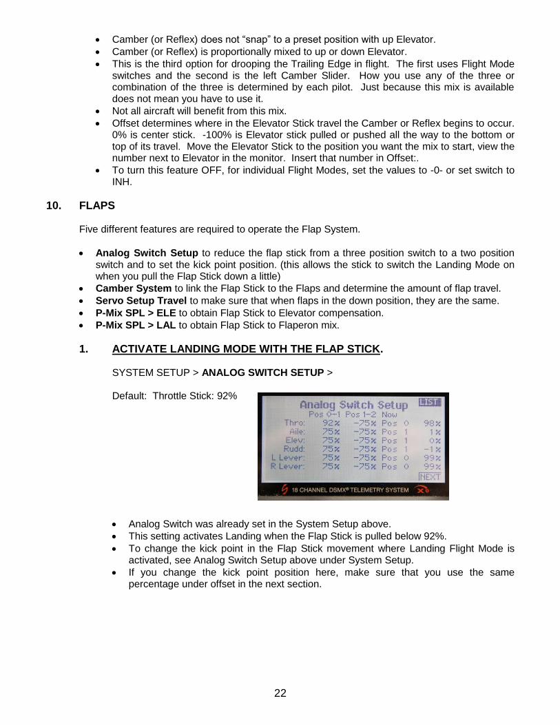
1. ACTIVATE LANDING MODE WITH THE FLAP STICK.
SYSTEM SETUP > ANALOG SWITCH SETUP >
Default: Throttle Stick: 92%
Analog Switch was already set in the System Setup above.
This setting activates Landing when the Flap Stick is pulled below 92%.
To change the kick point in the Flap Stick movement where Landing Flight Mode is activated, see Analog Switch Setup above under System Setup.
If you change the kick point position here, make sure that you use the same percentage under offset in the next section.
23
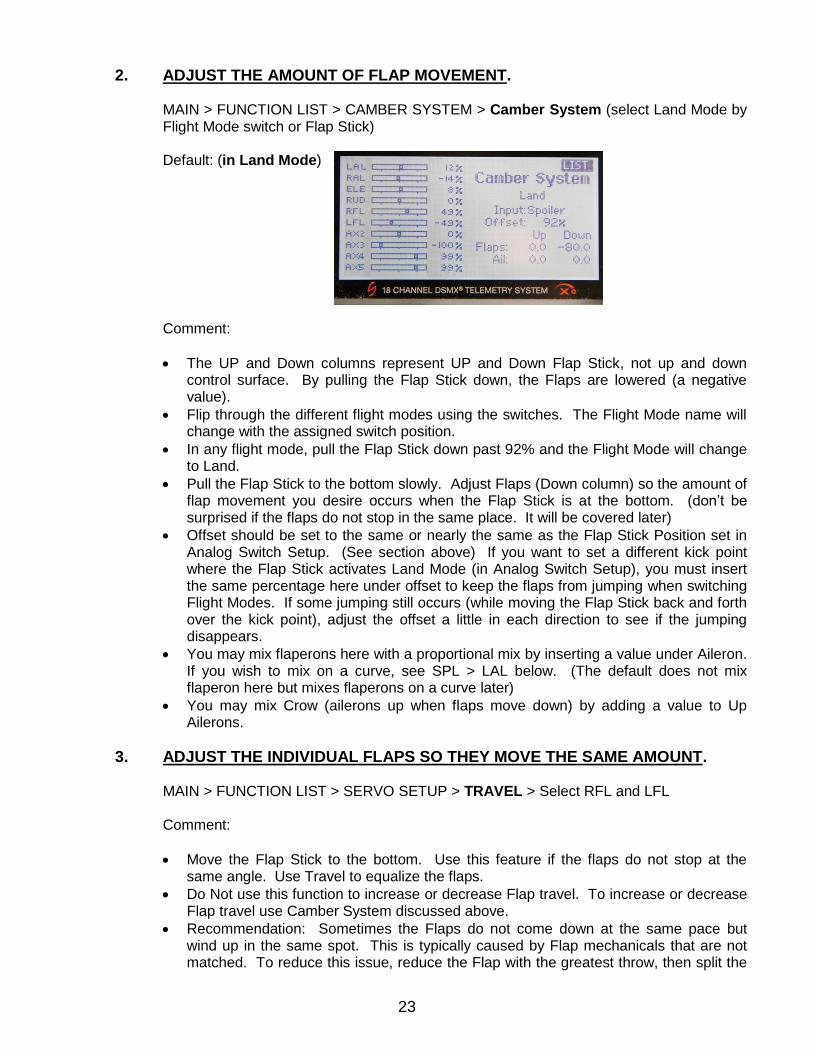
2. ADJUST THE AMOUNT OF FLAP MOVEMENT.
MAIN > FUNCTION LIST > CAMBER SYSTEM > Camber System (select Land Mode by Flight Mode switch or Flap Stick)
Default: (in Land Mode)
Comment:
The UP and Down columns represent UP and Down Flap Stick, not up and down control surface. By pulling the Flap Stick down, the Flaps are lowered (a negative value).
Flip through the different flight modes using the switches. The Flight Mode name will change with the assigned switch position.
In any flight mode, pull the Flap Stick down past 92% and the Flight Mode will change to Land.
Pull the Flap Stick to the bottom slowly. Adjust Flaps (Down column) so the amount of flap movement you desire occurs when the Flap Stick is at the bottom. (don’t be surprised if the flaps do not stop in the same place. It will be covered later)
Offset should be set to the same or nearly the same as the Flap Stick Position set in Analog Switch Setup. (See section above) If you want to set a different kick point where the Flap Stick activates Land Mode (in Analog Switch Setup), you must insert the same percentage here under offset to keep the flaps from jumping when switching Flight Modes. If some jumping still occurs (while moving the Flap Stick back and forth over the kick point), adjust the offset a little in each direction to see if the jumping disappears.
You may mix flaperons here with a proportional mix by inserting a value under Aileron. If you wish to mix on a curve, see SPL > LAL below. (The default does not mix flaperon here but mixes flaperons on a curve later)
You may mix Crow (ailerons up when flaps move down) by adding a value to Up Ailerons.
3. ADJUST THE INDIVIDUAL FLAPS SO THEY MOVE THE SAME AMOUNT.
MAIN > FUNCTION LIST > SERVO SETUP > TRAVEL > Select RFL and LFL Comment:
Move the Flap Stick to the bottom. Use this feature if the flaps do not stop at the same angle. Use Travel to equalize the flaps.
Do Not use this function to increase or decrease Flap travel. To increase or decrease Flap travel use Camber System discussed above.
Recommendation: Sometimes the Flaps do not come down at the same pace but wind up in the same spot. This is typically caused by Flap mechanicals that are not matched. To reduce this issue, reduce the Flap with the greatest throw, then split the
24
difference. (ie, if one flap is reduced 20%, then cut back the reduction to 10% and increase the other Flap 10%)
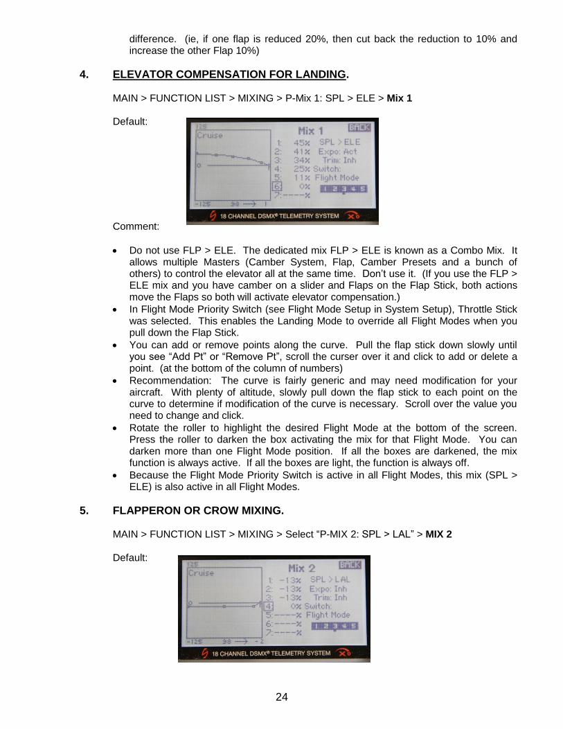
4. ELEVATOR COMPENSATION FOR LANDING.
MAIN > FUNCTION LIST > MIXING > P-Mix 1: SPL > ELE > Mix 1 Default: Comment:
Do not use FLP > ELE. The dedicated mix FLP > ELE is known as a Combo Mix. It allows multiple Masters (Camber System, Flap, Camber Presets and a bunch of others) to control the elevator all at the same time. Don’t use it. (If you use the FLP > ELE mix and you have camber on a slider and Flaps on the Flap Stick, both actions move the Flaps so both will activate elevator compensation.)
In Flight Mode Priority Switch (see Flight Mode Setup in System Setup), Throttle Stick was selected. This enables the Landing Mode to override all Flight Modes when you pull down the Flap Stick.
You can add or remove points along the curve. Pull the flap stick down slowly until you see “Add Pt” or “Remove Pt”, scroll the curser over it and click to add or delete a point. (at the bottom of the column of numbers)
Recommendation: The curve is fairly generic and may need modification for your aircraft. With plenty of altitude, slowly pull down the flap stick to each point on the curve to determine if modification of the curve is necessary. Scroll over the value you need to change and click.
Rotate the roller to highlight the desired Flight Mode at the bottom of the screen. Press the roller to darken the box activating the mix for that Flight Mode. You can darken more than one Flight Mode position. If all the boxes are darkened, the mix function is always active. If all the boxes are light, the function is always off.
Because the Flight Mode Priority Switch is active in all Flight Modes, this mix (SPL > ELE) is also active in all Flight Modes.
5. FLAPPERON OR CROW MIXING.
MAIN > FUNCTION LIST > MIXING > Select “P-MIX 2: SPL > LAL” > MIX 2
Default:
25
Comment:
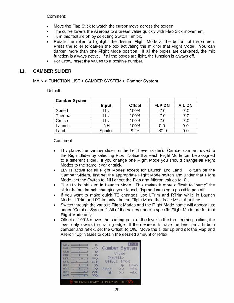
Move the Flap Stick to watch the cursor move across the screen.
The curve lowers the Ailerons to a preset value quickly with Flap Sick movement.
Turn this feature off by selecting Switch: Inhibit.
Rotate the roller to highlight the desired Flight Mode at the bottom of the screen. Press the roller to darken the box activating the mix for that Flight Mode. You can darken more than one Flight Mode position. If all the boxes are darkened, the mix function is always active. If all the boxes are light, the function is always off.
For Crow, reset the values to a positive number.
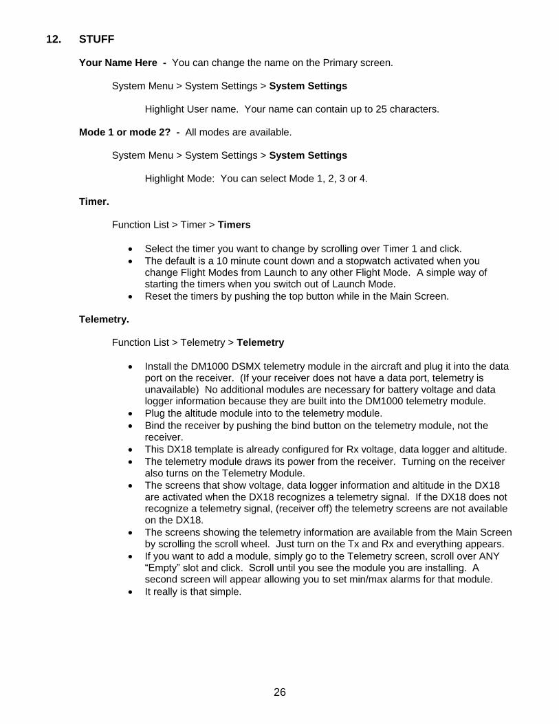
11. CAMBER SLIDER MAIN > FUNCTION LIST > CAMBER SYSTEM > Camber System
Default:
Camber System
Input Offset FLP DN AIL DN
Speed LLv 100% -7.0 -7.0
Thermal LLv 100% -7.0 -7.0
Cruise LLv 100% -7.0 -7.0
Launch INH 100% 0.0 0.0
Land Spoiler 92% -80.0 0.0
Comment:
LLv places the camber slider on the Left Lever (slider). Camber can be moved to the Right Slider by selecting RLv. Notice that each Flight Mode can be assigned to a different slider. If you change one Flight Mode you should change all Flight Modes to the same lever or stick.
LLv is active for all Flight Modes except for Launch and Land. To turn off the Camber Sliders, first set the appropriate Flight Mode switch and under that Flight Mode, set the Switch to INH or set the Flap and Aileron values to -0-.
The LLv is inhibited in Launch Mode. This makes it more difficult to “bump” the slider before launch changing your launch flap and causing a possible pop off.
If you want to make quick TE changes, use LTrim and RTrim while in Launch Mode. LTrim and RTrim only trim the Flight Mode that is active at that time.
Switch through the various Flight Modes and the Flight Mode name will appear just under “Camber System.” All of the values under a specific Flight Mode are for that Flight Mode only.
Offset of 100% moves the starting point of the lever to the top. In this position, the lever only lowers the trailing edge. If the desire is to have the lever provide both camber and reflex, set the Offset: to 0%. Move the slider up and set the Flap and Aileron “Up” values to obtain the desired amount of reflex.
26
12. STUFF Your Name Here - You can change the name on the Primary screen. System Menu > System Settings > System Settings Highlight User name. Your name can contain up to 25 characters.
Mode 1 or mode 2? - All modes are available.
System Menu > System Settings > System Settings
Highlight Mode: You can select Mode 1, 2, 3 or 4.
Timer.
Function List > Timer > Timers
Select the timer you want to change by scrolling over Timer 1 and click.
The default is a 10 minute count down and a stopwatch activated when you change Flight Modes from Launch to any other Flight Mode. A simple way of starting the timers when you switch out of Launch Mode.
Reset the timers by pushing the top button while in the Main Screen. Telemetry. Function List > Telemetry > Telemetry
Install the DM1000 DSMX telemetry module in the aircraft and plug it into the data port on the receiver. (If your receiver does not have a data port, telemetry is unavailable) No additional modules are necessary for battery voltage and data logger information because they are built into the DM1000 telemetry module.
Plug the altitude module into to the telemetry module.
Bind the receiver by pushing the bind button on the telemetry module, not the receiver.
This DX18 template is already configured for Rx voltage, data logger and altitude.
The telemetry module draws its power from the receiver. Turning on the receiver also turns on the Telemetry Module.
The screens that show voltage, data logger information and altitude in the DX18 are activated when the DX18 recognizes a telemetry signal. If the DX18 does not recognize a telemetry signal, (receiver off) the telemetry screens are not available on the DX18.
The screens showing the telemetry information are available from the Main Screen by scrolling the scroll wheel. Just turn on the Tx and Rx and everything appears.
If you want to add a module, simply go to the Telemetry screen, scroll over ANY “Empty” slot and click. Scroll until you see the module you are installing. A second screen will appear allowing you to set min/max alarms for that module.
It really is that simple.
27
Part 5 – Before You Fly.
1. RE-BIND THE RECEIVER. With the aircraft on the bench, receiver and transmitter on and
everything working, turn the transmitter off. Your control surfaces may jump to a different location. This is the same position the control surfaces will move to if there is a loss of signal to your aircraft in flight.
Whether or not this occurs may be because of the type and nature of the failsafe in your receiver. Some receivers return to servo center. Others perform a “hold last command” function. If your aircraft is turning when connection is lost, the aircraft will keep turning. Some receivers (typically the more expensive ones) provide an option of a preset failsafe. When the connection is lost, the control surfaces will move to a preset position. When you first bound the receiver and transmitter, the receiver remembers the position of the servos at that time. This was before you started adjusting your mechanicals. While adjusting your mechanicals, you may have changed servo arm positions, reset SubTrims and changed trim settings to get the control surface to properly center. Recall, the preset failsafe receiver remembers the servo position AT THE TIME OF BINDING, not the current servo arm position or current control surface position. If you lose connection, a receiver with a preset failsafe will return the servos to the position when they were first bound. In every case, this situation is not healthy for your aircraft. BEFORE YOU FLY, YOU MUST REBIND THE AIRCRAFT TO SET A NEW PRESET FAILSAFE. The new preset failsafe can be anything you want. From all surfaces returning to neutral to all kinds of crazy settings. The official method to set a new preset failsafe is; insert the bind plug, turn on the receiver and with the lights blinking, remove the bind plug. The lights should continue to blink. Move the transmitter control sticks to the desired preset failsafe and turn the radio on in bind mode. Wait until the systems connect. The above method makes you guess at a stick position. To be more precise in your selection of stick position, (Flaps slightly down with elevator compensation as an example) move the control surfaces to the desired position, (flap stick down to move the flaps and elevator to the desired position) and without changing the stick position, turn off the receiver, then the transmitter. Insert the bind plug, turn on the receiver (lights blinking) and without changing the stick position, bind using the procedure for your radio. Check again by turning the Transmitter off. The control surfaces should move to the position you selected.
2. FIRST FLIGHT. For the first trim flight, set the Elevator Trim to Common. After a new trim
setting is established for the elevator, return the Elevator Trim to F Mode. In the alternative, Trim the elevator while in cruise mode and do not use any of the other flight modes during that flight. Land and then use the Monitor Screen to adjust the other Flight Mode elevator settings to match Cruise Mode. Observe the numerical value in Cruise Mode, then flip the Flight Mode switches and trim the elevator until the value in all flight modes is the same. You now have a common base to start programming the other Flight Modes
3. ITS NEW – Don’t be a dummy - Range check it first.
This document is copyrighted by Sherman Knight. It is currently available, along with the template for download from the Seattle Area Soaring Society, Kennedy Composites, Soaring USA, and the Spektrum website. It is provided in a .pdf file. Send comments or feedback to [email protected]
28
Flight Mode Addendum It is easy to be overwhelmed when working with Flight Modes. But, it is overwhelming because we think it needs to be complicated, so it must be complicated. It really isn’t. Working the Flight Mode Setup is like working the seating chart for my daughter’s wedding. First, we need to determine how many are coming to the wedding. Once we know how many, we can order the correct number of tables for the reception. This would be similar to determining how many Flight Modes you need. Then, we have to determine the names of those coming to the reception. This would be similar to determining your Flight Mode names. Just like assigning a person to a spot at a table, we now have to assign the Flight Mode name to a switch. In the big picture, that is all that Flight Mode Setup does. What makes this interesting, is that my wife and daughter don’t agree on the seating arrangement and it needs to be changed. Changing the Flight Mode setup is about as difficult as changing the names on the seating chart. You only do four things in Flight Mode Setup. They are: 1. Sets the number of Flight Modes you are going to use. 2. Sets the switch or switches you want to use. 3. Sets the names of each Flight Mode you want. 4. Assigns a particular Flight Mode name to a particular switch position. The radio does all the rest. In features like Dual Rate, Differential, Camber Presets, and the available mixes, you select a switch to activate the feature. If you select Flight Mode as your switch, the DX18 automatically brings each of the Flight Modes into the feature. The correct number and name of the Flight Modes expands in each item of the Function List that can use Flight Modes. There is nothing more for you to do to establish Flight Modes in each feature. Here are the steps, follow then in the same order. 1. Go to the Flight Mode Wizard. 2. Select Custom. 3. In flight mode setup Select any two switches you want to use. Don’t worry here which switch is for which flight mode. 4. If you want a priority switch, choose it now. Don’t pay any attention to the rest of the screen. The priority switch overrides all other switches. 5. Next 6. Priority switch Leave it for now, more later. 7. Next 8. Flight Mode Table 9. Prev 10. Flight Mode Names. Use any name for any flight mode you want. Don’t worry about the sequence of the names. For Five Flight Modes use the names in the first column only. To avoid confusion, rename the names in the second column to something like FM6, FM7 and so on. 11. Next
29
12. Flight Mode Table. This is where the flexibility is amazing. Scroll the box over the matrix of names. Move both of the switches to the neutral (Cruise) position. The Flight Mode name in the middle of the 3 by 3 matrix should have the box around it. 13. Determine separately which flight mode you want on which switch. With the Flight Mode Switches in the center position, the box should be around the flight mode in the center. Click the scroll wheel and it will start to blink. Now scroll through the possible flight mode names you came up with earlier. Click on the one you want to assign to when the switches are in the neutral position. First switch position done. 14. Move a Flight Mode Switch to a different position and the box over the center flight mode should move to a new location. Click the scroll wheel until the box starts blinking. Scroll through all the different flight modes you have already named. Click on the one you want to use for that switch position. Second Switch position done. Continue for all the rest. 15. WHAT IT LOOKS LIKE ON THE SCREEN IS NOT IMPORTANT. All you are doing is choosing which flight mode goes with which switch position. This screen then directs the radio to update all the features in the radio. Choose Differential as an example. Differential now has all five flight modes . Each on available by flipping the appropriate Flight Mode Switch assigned by this table. If you are using five Flight Modes, there are nine choices in the matrix. Several names will be duplicated at different switch positions. 16. If only using five flight modes, recognize there is a difference between the first two columns of Flight Mode Names. Column A vs Column B. For now only use the names in column A.
Priority Switch Priority Switch is the granddaddy of all the Flight Mode Switches. It overrides ALL other flight modes. In addition to the usual two and three position switches, the DX18 is also covered with analog devices (stick, trims, sliders, knobs) that can also be used as a switch in addition their normal duty. The radio allows you to set two “kick points” on each analog device. This effectually divides the movement of the analog device into three separate areas. Each area is labeled just like a switch position, Pos 0, 1 and 2. In this case, we want the flap stick to switch the DX18 to Landing Mode overriding all other Flight Modes. We start by setting the “kick point” to an area near the top of the Flap Stick travel. That way we can bump the stick and not instantly go into land mode. For this example let’s say the kick point is set at 92% of travel. Everything above 92% would be position zero, and everything below 92% would be position one. We can then direct the DX18 to assign Flight Mode switches to Pos 0 and Land Mode to Pos 1 and 2 on the Flap Stick. 1. To activate Land Mode using the Flap Stick go back to the Flight Mode Setup page and select Throttle Stick for the priority switch. 2. Next 3. On the Priority Switch screen. Leave Pos 0 set to Switches. Set position 1 and 2 to Landing mode by using the scroll wheel and click. 4. Exit back to System Setup, scroll down to “Analog Switch Setup” and click. 5. On the Analog Switch Setup screen move the box over the Throttle row, first 75 percent. Pull down the flap stick and watch the number in the far right column change. Move the stick to get 92% in the far right hand column. With the blinking box over the first column, click the scroll wheel. The number in that box will change to 92%. Do not change the 75% in the second column. 6. Under the column “Now” appears the position of the switch as you move the flap stick. Watch the position number (Pos 1, 2 or3) change as you move the stick. You just established a “kick” point at 92% 7. Return to Flight Mode Setup. On the bottom of the page it shows the current flight mode. Move the Flap Stick down from the top. At 92% it will change to landing mode. 8. In any feature using Flight Modes, the Flight Mode name on the screen will change by pulling down the Flap Stick.
30
Balance Feature Addendum (use this if the flaps move at different rates) Earlier in the guide, we discussed how to make sure that the Flaps both stop at the same position in the down position. However, on the way down, the flaps may not move at the same pace. This can be changed with the Balance function. Function Menu > Servo Setup > Balance. Select the control surface (right or left Flap) Continue to scroll over the box below. Now pull the flap stick down until you get to the point where the flaps are the most unequal. A short vertical line moves across the screen. Go back to the scroll wheel and scroll the box over the number over the short vertical line. Increase or decrease the number until the flaps line up at that point. Pretty cool.
Mixing on a Curve Addendum. Adding and deleting points.
Each time you select a new mix for programming you will be asked to choose Normal or Curve. Normal really means a straight line. Think of it this way, if the line is not straight, then it is a curve. When you choose a Curve, the following screen only contains three points. One point on each end and one in the middle. If you do nothing more, your programming is limited to the same mixing that is available in Normal. Normal actually lets you make a curve. If the end points are in the same location, you can move the center point up or down, creating a kink in an otherwise straight line. (remember if it is not straight then it is curved) The following example mixes SPL > AX2. Adding a point is easy. Slowly pull the flap stick down and at the bottom of the column of numbers, suddenly “ADD Pt.” will appear. Continue to move the stick. Where ever you see “Add Pt.” you can do just that. Scroll the box over “Add Pt.” and click. A new point appears. Removing a point is just as easy. Move the flap stick and as soon as the short vertical moves over an existing point, “Remove Pt.” appears at the bottom of the column of numbers. Scroll the box over “Remove Pt.” and click. The point disappears.
V-Tail Addendum. If you have the typical v-tail aircraft, v-tail control horns on the bottom and servos on center line with servo arms pointed out, use V-Tail A. If you plug the servos in according to the servo assignment screen, one of the two stick movements will most likely be backwards. (elevator is correct but rudder is backwards and vice versa) If this is the case, pull the servo plugs from the receiver and reverse them. Trimming a v-tail is easy. Start by setting a dual rate for cruise mode. Make sure all the control surfaces move the same amount both up and down using endpoint adjustments. While flying the aircraft, yaw the aircraft using the rudder stick only. Notice if it pitches up or down. You want the aircraft to maintain a constant pitch while using the rudder. If it pitches up or down, you can correct this by using V-Tail Differential. This feature provides for both positive and negative adjustments. If the aircraft pitches up, adjust the V-Tail Differential so the rudder stick moves the control surfaces downward more that up. Measure the difference at full rudder stick. Do the opposite is the aircraft pitches down. Do not use V-Tail B.
31
In AirWare ver 1.0, V-Tail Differential is available to the rudder stick. Unfortunately, if Rudder is Mixed to Aileron, this differential is unavailable with the Aileron Stick. This should be fixed with the next update. Coming Soon……… Electric Soaring and how to control the motor functions. F5J will be interested here. Base Line Trim Disclaimer: This Guide and the accompanying template work on my personal aircraft. They have not been verified on different aircraft, with different configurations of servos, wiring harness or Y-harness (if any). Use them at your own risk. Before you fly, verify that ALL SWITCHES work in their intended way, and that ALL INTENTIONALLY INACTIVE SWITCHES DON’T ACTUALLY DO SOMETHING. (in this guide, only two switches do anything!)
If a stick, trim or switch cause control surfaces move in manner not intended, do not fly until the issue is resolved.