Embed Size (px)
Citation preview
SPEM 2.0 Extension for Pervasive Information Systems
JOSÉ E. FERNANDES
Dept. of Informatics and Communications
School of Technology and Management
Polytechnic Institute of Bragança
5301-854 Bragança,
PORTUGAL
RICARDO J. MACHADO
Dept. de Sistemas de Informação
Escola de Engenharia
Universidade do Minho
4800-058 Guimarães
PORTUGAL
Abstract: Pervasive computing is a research field of computing technology that aims to achieve a new
computing paradigm. In this paradigm, the physical environment has a high degree of pervasiveness and
availability of computers and other information technology (IT) devices, usually with communication
capabilities. Pervasive Information Systems (PIS), composed by these kinds of devices, bring issues that
challenge software development for them. Model-Driven Development (MDD), strongly focusing and relying
on models, has the potential to allow: the use of concepts closer to the domain and the reduction of semantic
gaps; higher automation and lower dependency to technological changes; higher capture of expert knowledge
and reuse; an overall increased productivity. Along with the focus and use of models, software development
processes are fundamental to efficient development efforts of successful software systems. For the description
of processes, Software & Systems Process Engineering Meta-Model Specification (SPEM) is the current
standard specification published by the Object Management Group (OMG). This paper presents an extension
to SPEM (version 2.0) Base Plug-In Profile that includes stereotypes needed to support a suitable structural
process organization for MDD approaches aiming to develop software for PIS. A case study is provided to
evaluate the applicability of the extension.
Key-Words: MDD, PIS, SPEM, pervasive, ubiquitous, software engineering, process, information systems.
1 Introduction Pervasive/Ubiquitous Computing [1, 2] represents a
recent thinking about computing and its integration
on users’ life and environment . It aims to achieve a
new computing paradigm, one in which there is a
high degree of pervasiveness and availability of
interconnected IT devices in the physical
environment. In consequence, interest arises in new
or improved forms of information systems, such as
Pervasive Information System (PIS) [3], that take
advantage of the overall availability of computing.
Dissemination of computing and heterogeneous
information technology devices and platforms, the
high pace of technological innovations, and volatile
requirements challenge software development for
these new forms of systems.
During last decade, Model-Driven Development
has gained emphasis due to efforts and promotion of
standards and initiatives on modeling [4]. Raising
the traditional level of abstraction for system’s
conception and design, MDD automates, as much as
possible, the transformation of models and the
generation of the final code. An MDD approach to
software development enables higher independence
from the technological platform that supports the
realization of the system. MDD has the potential to
offer key pathways that enable software developers
to cope with complexity inherent to PIS. MDD
enhances the efficiency of the software
development, the resilience, the robustness, and the
evolution of systems. CASE tools, which are of
primary importance to an effective MDD
development, have evolved to accommodate MDD
concepts and techniques. Current MDD concepts
and techniques and supporting CASE tools are not
sufficient for an MDD approach to be adopted in the
context of PIS development. A proper PIS
development demands an approach that recognizes
particularities of PIS and that takes advantage of a
MDD orientation. This approach has to establish a
suitable strategy for the development of PIS based
on appropriate conceptual framework.
Software Development Processes (SDPs), as well
as generalized adoption of models, are fundamental
to efficient development efforts of successful
software systems. SDPs, incorporating best
practices, evolved from ad-hoc, passing by
WSEAS TRANSACTIONS on COMPUTERS José E. Fernandes, Ricardo J. Machado
E-ISSN: 2224-2872 319 Issue 9, Volume 11, September 2012
waterfall, to iterative and incremental [5]. SDPs are
subject of research, improvement, practice, and
standardization. SPEM [6] is a current standard
published by the OMG [7] for the description of
systems and software processes. SPEM provides, to
process engineers, conceptions for modeling method
contents and processes. Published SPEM research
works haven’t focused yet MDD approaches that
take explicitly into account PIS characteristics. The
work described in this paper contributes to this
specific matter. This paper presents a SPEM 2.0
Base Plug-in extension based on a conceptual
framework suitable for software development for
pervasive information systems. This extension aims
to provide process engineers with model elements
that allow them to more precisely describe software
processes for software development of PIS.
This document structures its content as follows:
section 1 contextualizes software development for
pervasive information systems; section 2 gives
insight into related works; section 3 gives an
overview of the proposed development framework
for PIS and presents the extension to SPEM 2.0
Base Plug-in; section 4 presents a case study used to
evaluate the extension applicability; section 5
presents the conclusions and finishes this document.
2 Related Work Reasoning about software development processes
needs solid conceptual structures and convenient
representations for description of relevant process
characteristics. Standard meta-modeling approaches
for modeling processes, such as SPEM, provide
such conceptions and representations. SPEM is a
process meta-modeling approach that is subject of
use, extension, and research by the process
engineering community. Some examples of these
uses and extensions are next briefly pointed out. SPEM is used as a language to express process
proposals aiming to achieve particular goals or to be
implemented by supporting tools. In the context of
security requirements, D. Mellado et al. [8] use
SPEM 2.0 to describe a security requirements
engineering process for SPL (SREPPLine). The
framework proposed defines, besides the process, a
reference meta-model and a tool that implements the
meta-model and supports the process. They present
the SREPPLine structure, the SREPPLine activities
structure, a XML grammar for the security reference
model, and tables defining the most important work
products, guidance, roles, and task definitions for
the SREPPLine process. M. Kuma et al. [9] use
SPEM 2.0 to model a software development process
that extends the AUTOSAR (AUTomotive Open
System ARchitecture) standard [10]. N. Ibrahim et
al. [11] use SPEM 2.0 to express the process
defined in the proposed approach for propagating
requirement changes into high-level designs. This
approach also suggests a product meta-model that,
defining a conceptual model for volatile
requirements and its requirements, sustains the
process model. O. Avila-García et al. [12] propose a
DSTL (Domain-Specific Transformation Language)
called MTTL (Model Template Transformation
Language) to specify transformations
(specializations) of model templates based on
feature models. They use SPEM 2.0 to describe the
product and the SPL (Software Product Line)
development process for a model family. N. Kerzazi
et al. [13] present an automated approach to
software process modeling called DSL4SPM
(Domain-Specific Language for Software Process
Modeling). This approach provides a conceptual
framework for designing processes and support to a
multi-view oriented process modeling. A tool, also
called DSL4SPM (and which implements SPEM
2.0), demonstrates the potential of the approach.
The approach explores attributed relationships
among model components in order to enhance the
semantics of process models, allowing for multiple
views. In a Software Process Improvement (SPI)
perspective, the tool provides support for process
model evolution with comparison of evolution of
states. In the context of SPI, P. V. Martins et al. [14]
performs a comparative study of process meta-
models approaches, namely SPEM, OPEN Process
Framework (OPF), and Standard Meta-model for
Software Development Methodologies (SMSDM).
They propose a process meta-model (called PIT-
ProcessM) addressing issues related to SPI.
SPEM is also subject of extension proposals in
order to acquire properties or to be able to fulfill
specific needs in process engineering; some of these
extensions also provide supporting tools. M. Silva et
al. [15] present a meta-model for software artifacts
providing a new way to represent artifact content.
This is realized through the provision of an
extension to the Unified Modeling Language (UML)
[16]/Meta Object Facility (MOF)[17] and SPEM. D.
Silingas et al. [18] present a framework supporting
wizard-based modeling guidance in UML tools.
Their work presents a UML profile that extends
SPEM 2.0 and supports the specification of method
models in order to generate the appropriate
modeling guidance wizards. A MagicDraw plug-in
[19] implements a prototype of the framework and
two different wizards illustrate the approach. In the
context of process enactment, several extensions to
SPEM are next referred. R. Ellner et al. [20] analyze
WSEAS TRANSACTIONS on COMPUTERS José E. Fernandes, Ricardo J. Machado
E-ISSN: 2224-2872 320 Issue 9, Volume 11, September 2012
SPEM issues regarding behavior modeling,
planning, and configuration of SPEM. Considering
these issues, they propose a SPEM 2.0 extension to
enable automatic enactment of SDPs. The solution
proposed goes by the substitution of behavior
interfacing concepts of SPEM and the introduction
of additional extensions to support the enactment of
SDPs. R. Bendraou et al. [21] propose an extension
to SPEM 2.0 specification (called xSPEM), that
provides concepts deemed as needed to enact a
process model. These concepts allow SPEM 2.0
process models “to be checked through a mapping
to Petri nets and monitored through a
transformation into BPEL” [21]. D. Riesco et al.
[22] aim to formalize the transformation of SPEM
(v1.1) activities into Business Process Model and
Notation (BPMN) [23] subprocesses. This allows
that a software process, described with SPEM 1.1,
may be used as input into a workflow engine. This
work establishes a basis to automate a SDP by “(…)
automation of business processes using workflow
technology”. Formalisms are expressed using RSL
(RAISE Specification Language) formal language
of RAISE (Rigorous Approach to Industrial
Software Engineering) method. N. Debnath et al.
[24] propose a solution to “automate the
management of activities” of a SDP described by a
SPEM (version 1.1) specification. This is
accomplished through transformation of these
activities into workflow subprocesses based on the
BPMN standard. The transformation is done by the
language Query/Views/Transformation (QVT)
standard [25]. The BPMN model can be “(…)
turned into a workflow specification under
BPEL4WS [26] or XPDL [27] languages”, which
may be used in a workflow engine. Also in the
context of process enactment, but additionally
taking into account a model-driven process
modeling context, R. Maciel et al. [28] present an
integrated approach for MDA process modeling and
enactment. They extend SPEM 2.0 meta-model with
some specializations for modeling MDA processes
and provide a supporting tool. They present two
case studies that allowed the evaluation of the
approach. A. Koudri et al. [29] consider that current
process modeling languages lack on integrating
Model Based Engineering (MBE) into system and
software process models. As such, they present an
extension to SPEM 2.0, called MODAL (Model
Oriented Development Application Language) that
introduces additional concepts for the definition and
elicitation of a model-based process. Among the
concepts introduced or refined in this extension are:
intention, strategy, models as work products,
process components, and constraints. In the context
of process variability, T. Martínez-Ruiz et al. [30]
consider that for processes which are to be adapted
for different contexts, a Software Product Line
(SPL) based approach is a proper approach. The
authors consider that SPEM 2.0 does not provide
suitable mechanisms for such approach.
Consequently, they suggest new variability
mechanisms based on concepts of variation points
and variants for modeling a SPL. These mechanisms
are proposed in an extension to SPEM 2.0.
None of the research works presented deals
simultaneously with MDD concerns and PIS issues.
Some of the extensions described touch in some of
concerns also considered in research work herein
presented: (i) research works [28] and [29] deal
with tailoring SPEM in order to incorporate MDD
concerns; (ii) research work [30] focus on software
process lines and deals with variability. As it will be
next explained, the conceptual framework for PIS
and the proposed extension deal, in some extent,
with functional variability that derives into
elementary development processes. The work
presented in this paper considers a conceptual
framework for PIS. This framework explicitly deals
with MDD and PIS concerns and proposes a
consistent strategy for structuring software
development for this kind of systems.
3 Extending SPEM for PIS This section presents the research work performed
for providing a suitable approach and a SPEM
representation to software development in the
context of pervasive information systems.
3.1 Conceptual development framework Research has been performed [31] to bring the
application of MDD concepts and techniques to
software of PIS. We consider [3] a conceptual
framework to sustain an approach for software
development of PIS that take into account MDD
potential and the PIS characteristics, particularly,
heterogeneity and functional variability. The
conceptual development framework introduces and
describes concepts framed on three structural
perspectives called dimensions. Based in these
dimensions, the development framework considers
two main development views: one concerning the
overall development process, and a second
concerning to individual development processes.
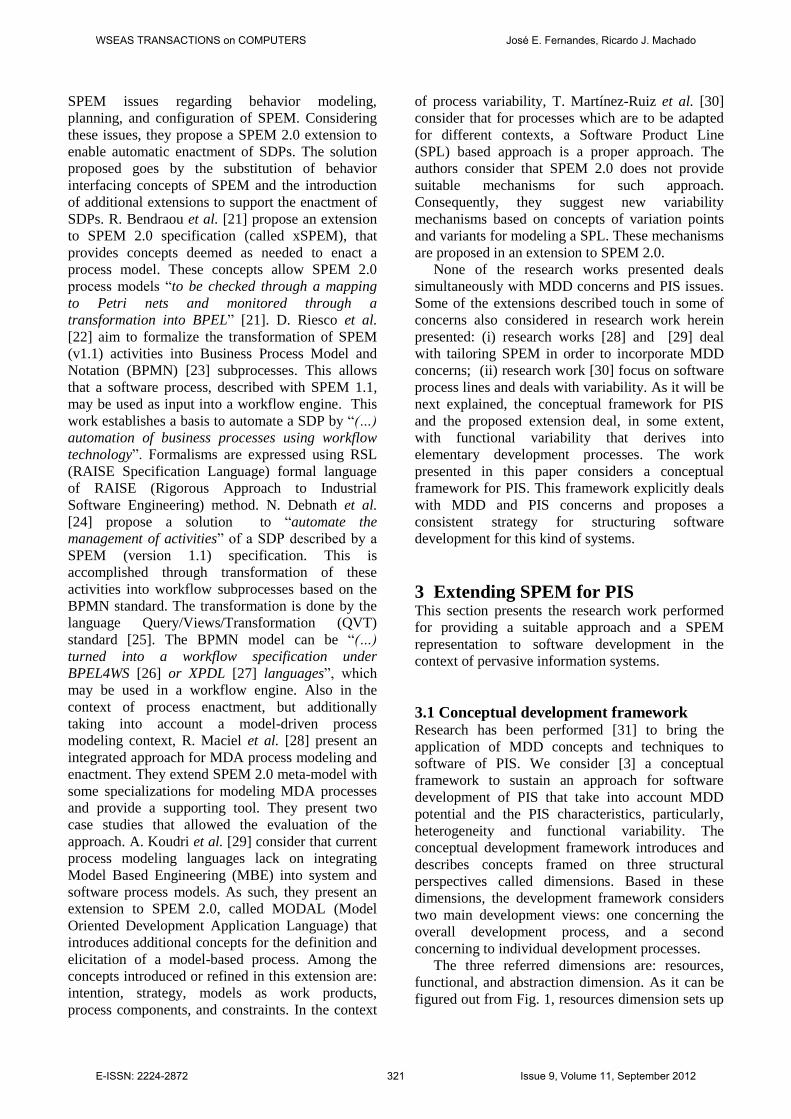
The three referred dimensions are: resources,
functional, and abstraction dimension. As it can be
figured out from Fig. 1, resources dimension sets up
WSEAS TRANSACTIONS on COMPUTERS José E. Fernandes, Ricardo J. Machado
E-ISSN: 2224-2872 321 Issue 9, Volume 11, September 2012
several categories of devices with similar
characteristics and capabilities. The functional
dimension sets up different functionalities required
in the system that can be assigned to devices in the
system for its realization. The assignment of a
specific functional profile to a specific resource
category results in a functional profile instance that
is realized by devices in that resource category.
Fig. 1 - Functional and Resources Dimension.
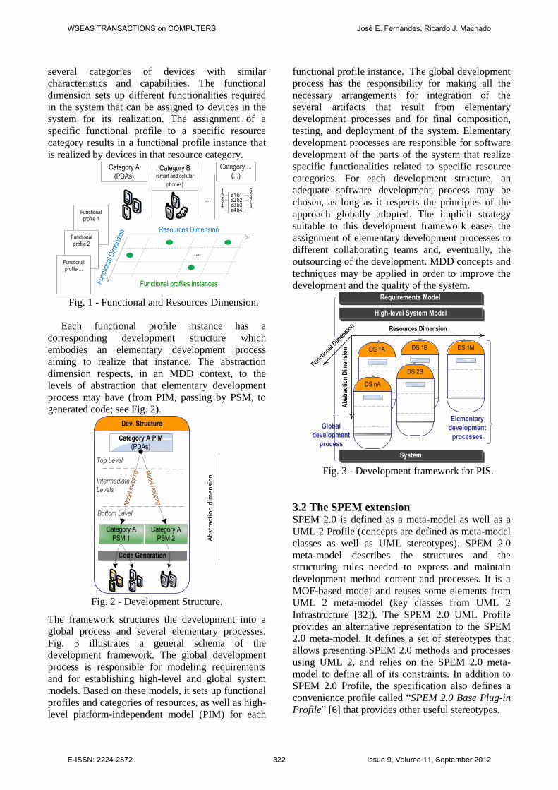
Each functional profile instance has a
corresponding development structure which
embodies an elementary development process
aiming to realize that instance. The abstraction
dimension respects, in an MDD context, to the
levels of abstraction that elementary development
process may have (from PIM, passing by PSM, to
generated code; see Fig. 2).
Fig. 2 - Development Structure.
The framework structures the development into a
global process and several elementary processes.
Fig. 3 illustrates a general schema of the
development framework. The global development
process is responsible for modeling requirements
and for establishing high-level and global system
models. Based on these models, it sets up functional
profiles and categories of resources, as well as high-
level platform-independent model (PIM) for each
functional profile instance. The global development
process has the responsibility for making all the
necessary arrangements for integration of the
several artifacts that result from elementary
development processes and for final composition,
testing, and deployment of the system. Elementary
development processes are responsible for software
development of the parts of the system that realize
specific functionalities related to specific resource
categories. For each development structure, an
adequate software development process may be
chosen, as long as it respects the principles of the
approach globally adopted. The implicit strategy
suitable to this development framework eases the
assignment of elementary development processes to
different collaborating teams and, eventually, the
outsourcing of the development. MDD concepts and
techniques may be applied in order to improve the
development and the quality of the system.
Fig. 3 - Development framework for PIS.
3.2 The SPEM extension SPEM 2.0 is defined as a meta-model as well as a
UML 2 Profile (concepts are defined as meta-model
classes as well as UML stereotypes). SPEM 2.0
meta-model describes the structures and the
structuring rules needed to express and maintain
development method content and processes. It is a
MOF-based model and reuses some elements from
UML 2 meta-model (key classes from UML 2
Infrastructure [32]). The SPEM 2.0 UML Profile
provides an alternative representation to the SPEM
2.0 meta-model. It defines a set of stereotypes that
allows presenting SPEM 2.0 methods and processes
using UML 2, and relies on the SPEM 2.0 meta-
model to define all of its constraints. In addition to
SPEM 2.0 Profile, the specification also defines a
convenience profile called “SPEM 2.0 Base Plug-in
Profile” [6] that provides other useful stereotypes.
Func
tiona
l Dim
ensi
on
Resources Dimension
Category A
(PDAs)Category B
(smart and cellular
phones)
Category ...
(...)
...a1
1
a223
a34a4
b1b2b3b4
5678
Functional
profile 1
Functional
profile 2
Functional
profile ...
...
Functional profiles instances
Code Generation
Category A PIM
(PDAs)
Category A
PSM 1
Mod
el m
appi
ng
Model m
apping
Top Level
Intermediate
Levels
Bottom Level
Dev. Structure
Category A
PSM 2 Ab
stra
ctio
n d
imen
sio
n
Resources Dimension
DS 1B
Global
development
process
Elementary
development
processes
Requirements Model
High-level System Model
DS 2B
DS 1MDS 1A
DS nA
Functio
nal D
imen
sion
Ab
stra
ctio
n D
imen
sio
n
System
WSEAS TRANSACTIONS on COMPUTERS José E. Fernandes, Ricardo J. Machado
E-ISSN: 2224-2872 322 Issue 9, Volume 11, September 2012
In the context of the software development for
PIS, we propose additional stereotypes to the SPEM
2.0 Base Plug-in. This extension does not affect the
SPEM meta-model itself. The proposed stereotypes
extend two main groups of stereotypes defined in
SPEM 2.0 Base Plug-in: the “ActivityKind” and
“WorkProductKind” stereotypes. Fig. 4 and Fig. 5
illustrate, respectively, the new "ActivityKind" and
"WorkProductKind" stereotypes (white boxes
contain the predefined kinds; grey boxes contain the
proposed additional kinds). The following
paragraphs describe these new stereotypes, grouped
by each of those kinds.
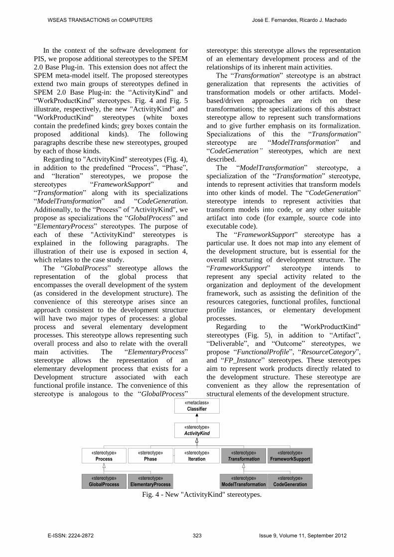
Regarding to "ActivityKind" stereotypes (Fig. 4),
in addition to the predefined “Process”, “Phase”,
and “Iteration” stereotypes, we propose the
stereotypes “FrameworkSupport” and
“Transformation” along with its specializations
“ModelTransformation” and “CodeGeneration.
Additionally, to the “Process” of "ActivityKind", we
propose as specializations the “GlobalProcess” and
“ElementaryProcess” stereotypes. The purpose of
each of these "ActivityKind" stereotypes is
explained in the following paragraphs. The
illustration of their use is exposed in section 4,
which relates to the case study.
The “GlobalProcess” stereotype allows the
representation of the global process that
encompasses the overall development of the system
(as considered in the development structure). The
convenience of this stereotype arises since an
approach consistent to the development structure
will have two major types of processes: a global
process and several elementary development
processes. This stereotype allows representing such
overall process and also to relate with the overall
main activities. The “ElementaryProcess”
stereotype allows the representation of an
elementary development process that exists for a
Development structure associated with each
functional profile instance. The convenience of this
stereotype is analogous to the “GlobalProcess”
stereotype: this stereotype allows the representation
of an elementary development process and of the
relationships of its inherent main activities.
The “Transformation” stereotype is an abstract
generalization that represents the activities of
transformation models or other artifacts. Model-
based/driven approaches are rich on these
transformations; the specializations of this abstract
stereotype allow to represent such transformations
and to give further emphasis on its formalization.
Specializations of this the “Transformation”
stereotype are “ModelTransformation” and
“CodeGeneration” stereotypes, which are next
described.
The “ModelTransformation” stereotype, a
specialization of the “Transformation” stereotype,
intends to represent activities that transform models
into other kinds of model. The “CodeGeneration”
stereotype intends to represent activities that
transform models into code, or any other suitable
artifact into code (for example, source code into
executable code).
The “FrameworkSupport” stereotype has a
particular use. It does not map into any element of
the development structure, but is essential for the
overall structuring of development structure. The
“FrameworkSupport” stereotype intends to
represent any special activity related to the
organization and deployment of the development
framework, such as assisting the definition of the
resources categories, functional profiles, functional
profile instances, or elementary development
processes.
Regarding to the "WorkProductKind"
stereotypes (Fig. 5), in addition to “Artifact”,
“Deliverable”, and “Outcome” stereotypes, we
propose “FunctionalProfile”, “ResourceCategory”,
and “FP_Instance” stereotypes. These stereotypes
aim to represent work products directly related to
the development structure. These stereotype are
convenient as they allow the representation of
structural elements of the development structure.
Fig. 4 - New "ActivityKind" stereotypes.
«stereotype»
ActivityKind
«stereotype»
Process
«stereotype»
Phase
«stereotype»
Iteration
«stereotype»
GlobalProcess
«stereotype»
ElementaryProcess
«stereotype»
Transformation
«stereotype»
ModelTransformation
«stereotype»
CodeGeneration
«stereotype»
FrameworkSupport
«metaclass»
Classifier
WSEAS TRANSACTIONS on COMPUTERS José E. Fernandes, Ricardo J. Machado
E-ISSN: 2224-2872 323 Issue 9, Volume 11, September 2012
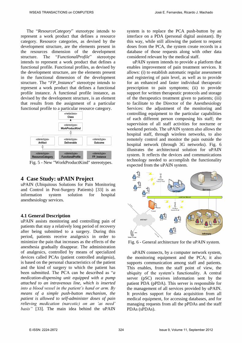
The “ResourceCategory” stereotype intends to
represent a work product that defines a resource
category. Resource categories, as devised by the
development structure, are the elements present in
the resources dimension of the development
structure. The “FunctionalProfile” stereotype
intends to represent a work product that defines a
functional profile. Functional profiles, as devised by
the development structure, are the elements present
in the functional dimension of the development
structure. The “FP_Instance” stereotype intends to
represent a work product that defines a functional
profile instance. A functional profile instance, as
devised by the development structure, is an element
that results from the assignment of a particular
functional profile to a particular resource category.
«stereotype»
WorkProductKind
«stereotype»
Artifact
«stereotype»
Deliverable
«stereotype»
Outcome
«metaclass»
Class
«stereotype»
ResourceCategory
«stereotype»
FunctionalProfile
«stereotype»
FP_Instance
Fig. 5 - New "WorkProductKind" stereotypes.
4 Case Study: uPAIN Project uPAIN (Ubiquitous Solutions for Pain Monitoring
and Control in Post-Surgery Patients) [33] is an
information system solution for hospital
anesthesiology services.
4.1 General Description uPAIN assists monitoring and controlling pain of
patients that stay a relatively long period of recovery
after being submitted to a surgery. During this
period, patients receive analgesics in order to
minimize the pain that increases as the effects of the
anesthesia gradually disappear. The administration
of analgesics, controlled by means of specialized
devices called PCAs (patient controlled analgesia),
is based on the personal characteristics of the patient
and the kind of surgery to which the patient has
been submitted. The PCA can be described as “a
medication-dispensing unit equipped with a pump
attached to an intravenous line, which is inserted
into a blood vessel in the patient’s hand or arm. By
means of a simple push-button mechanism, the
patient is allowed to self-administer doses of pain
relieving medication (narcotic) on an ‘as need’
basis” [33]. The main idea behind the uPAIN
system is to replace the PCA push-button by an
interface on a PDA (personal digital assistant). By
this way, while still allowing the patient to request
doses from the PCA, the system create records in a
database of those requests along with other data
considered relevant by the medical staff.
uPAIN system intends to provide a platform that
enables improvement of pain treatment services. It
allows: (i) to establish automatic regular assessment
and registering of pain level, as well as to provide
for an enhanced and faster individual therapeutic
prescription to pain symptoms; (ii) to provide
support for written therapeutic protocols and storage
of the therapeutics treatment given to patients; (iii)
to facilitate to the Director of the Anesthesiology
Services: the adjustment of the monitoring and
controlling equipment to the particular capabilities
of each different person composing his staff; the
supervision of all staff activities for nocturne or
weekend periods. The uPAIN system also allows the
hospital staff, through wireless networks, to also
remotely control and monitor the pain outside the
hospital network (through 3G networks). Fig. 6
illustrates the architectural solution for uPAIN
system. It reflects the devices and communications
technology needed to accomplish the functionality
expected from the uPAIN system.
Fig. 6 - General architecture for the uPAIN system.
uPAIN connects, by a computer network system,
the monitoring equipment and the PCA; it also
supports communication among staff and patients.
This enables, from the staff point of view, the
ubiquity of the system’s functionality. A central
server (pSC) receives information sent by the
patient PDA (pPDA). This server is responsible for
the management of all services provided by uPAIN.
It provides support for data acquisition from all
medical equipment, for accessing databases, and for
managing requests from all the pPDAs and the staff
PDAs (sPDAs).
WSEAS TRANSACTIONS on COMPUTERS José E. Fernandes, Ricardo J. Machado
E-ISSN: 2224-2872 324 Issue 9, Volume 11, September 2012
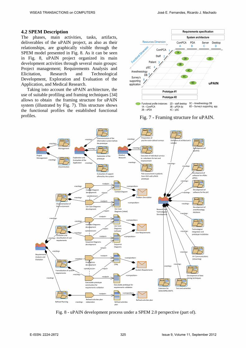
4.2 SPEM Description The phases, main activities, tasks, artifacts,
deliverables of the uPAIN project, as also as their
relationships, are graphically visible through the
SPEM model presented in Fig. 8. As it can be seen
in Fig. 8, uPAIN project organized its main
development activities through several main groups:
Project management; Requirements Analysis and
Elicitation, Research and Technological
Development, Exploration and Evaluation of the
Application, and Medical Research.
Taking into account the uPAIN architecture, the
use of suitable profiling and framing techniques [34]
allows to obtain the framing structure for uPAIN
system (illustrated by Fig. 7). This structure shows
the functional profiles the established functional
profiles.
Fig. 7 - Framing structure for uPAIN.
Fig. 8 - uPAIN development process under a SPEM 2.0 perspective (part of).
A B C D
1A
4C
6D
2B 2D
ComPCA PDA Server Desktop
ComPCA
Staff
Patient
pSC
Anesthesiology
DB
System architecture
3B
5C
Requirements specification
Prototype #2
Prototype #1
1
2
3
4
5
6
Functional profile instances:
1A – ComPCA
2B – sPDA
Survey’s
supporting
application
2D – staff desktop
3B – pPDA fpi
4C – pSC
5C – Anesthesiology DB
6D – Survey’s supporting app.
Functi
onal
Dimen
sion
Resources Dimension
uPAIN
Project
Management
Management
Dissemination
Requirements
Analysis and
Elicitation
Characterization of
the Environment
Elicitation and
classification of user
requirements
Formalization of system
requirements
Refined Planning
Research and
Technological
Development
Definition of architecture's
solution
Development of
comPCA
Development of
software for sPDAs
pPDAs
Development of
software for the pSC
Development of
anesthesiology
database
Technological
integration and
prototype installation
AV Communications
(streaming)
Development of data
mining techniques
Test and correctionExtension for
GSM/GPRS/UMTS
Exploration and
Evaluation of the
Application
Characterization of the
information system before
the prototype
Exploration of the
prototype
Evaluation of support
offered by the system
Medical
Research
Preparation of
psycho-socio-cultural surveys
Execution of individual surveys
to volunteers for test and
improvement
Pain assessment in patients
from HSO with uPAIN
prototype
Context Diagram
development
Use Case Diagrams
development
Context Diagram
Use Case
Diagrams [initial]
Problem Description
Use Case Diagrams
development
Sequence Diagrams
development
Use Case
Diagrams
[refined]
Sequence
Diagrams
Petri lattices
development CPNs
Refined activities
plan
Executable prototype
construction for
requirements validation
Executable prototype for
requirements validation
System Requirements
Refined activities plan
elaborationRefined activities plan
User Requirements
«output»
«nesting»
«nesting»
«output»
«input»
«composition»
«composition»
«input»
«nesting»
«nesting»
«nesting»
«nesting»
«composition»
«nesting»
«nesting»
«composition»
«nesting»
«nesting»
«nesting» «predecessor»
«output»
«nesting»
«nesting»
«input»
«composition» «output»
«nesting»
«input»
«predecessor»
«input»
«composition» «output»
«nesting»
«nesting»
«nesting»
«nesting»
«nesting»
«predecessor»
«output»
«nesting»
«composition» «output»
«nesting»
«nesting»
«nesting»
«nesting»
«nesting»
«nesting»
«nesting»
«nesting»
«nesting»
WSEAS TRANSACTIONS on COMPUTERS José E. Fernandes, Ricardo J. Machado
E-ISSN: 2224-2872 325 Issue 9, Volume 11, September 2012

Fig. 9 describes part uPAIN project according to
the conceptual development framework and using
the extended stereotypes. The stereotypes enable the
explicit representation of resource categories,
functional profiles, and functional profile instances
associated to the system. In Fig. 9 we can observe
that the stereotype «FrameworkSupport» fulfills a
central role on the organization and realization of
the conceptual development structure (as presented
in previous section describing this SPEM
extension). Fig. 10 presents a complementary
perspective that gives emphasis to the elementary
processes and the main activities they incorporate.
Particularly, it shows a model transformation
activity, named “4SRS application” and identified
by the corresponding stereotype
«ModelTransformation»; the 4SRS (4 Step Rule-
Set) technique allows the transformation of user
requirements into a logical system-level architecture
representing system requirements.
5 Conclusion This paper describes a SPEM extension based on the
conceptual development framework for PIS. This
extension differs from other SPEM extensions, since
we extend the SPEM Base Plug-In instead of the
SPEM meta-model. By means of a real case study,
the extension proved to be able to: (i) suitably
represent the concepts inherent to referenced
framework, which allowed for a clear perception of
the application of inherent concepts; (ii) represent
some of the MDD fundamental concepts, such as
model transformations. The use of this extension
revealed as being able to provide support to: (i)
sustain a structured and well-organized set of
development process elements; (ii) cope with
heterogeneity and quantity of computational devices
(through the concepts of resources categories,
functional profiles, and functional profile instances);
(iii) promote a model-based/driven approach to
software development (through use of
transformations).
Regarding future work, it is of interest to
alternatively express this extension through the
SPEM meta-model itself, to perform a deeper
integration of process variability mechanisms,
MDD, process enactment, and to explore a
conception of model-based/driven visibility.
Fig. 9 - uPAIN development process with extended SPEM diagram (major structuring elements).
Research and Technological Development
«FrameworkSuppo...
Framework Creation
«FrameworkSupport»
Functional Profiles Definition
«FrameworkSupport»
FP Instances Definition
«FrameworkSupport»
Elementary Processes Creation
«FrameworkSupport»
Resources Categories Definition
«GlobalProcess»uPAIN
«ResourceCategory»
comPCA
«ResourceCategory»
PDAs
«ResourceCategory»
Server
«ResourceCategory»
Desktop
«FunctionalProfile»
ComPCA
Resource Categories Functional Profiles
«FunctionalProfile»
Staff
«FunctionalProfile»
Patient
«FunctionalProfile»
pSC
Functional Profile Instances
«FunctionalProfile»
Anesthesiology DB
«FunctionalProfile»
Survey' supporting app
«FP_Instance»
1A - ComPCA
«FP_Instance»
2B - sPDA
«FP_Instance»
3B - pPDA
«FP_Instance»
4C - pSC
«FP_Instance»
5C - Anesthesiology DB
«FP_Instance»
2D - staff Desktop
«FP_Instance»
6D - Survey's supporting app
«ElementaryProcess»
1A - ComPCA
«ElementaryProcess»
2B - sPDA
«ElementaryProcess»
3B - pPDA
«ElementaryProcess»
4C - pSC
«ElementaryProcess»
5C - Anesthesiology DB
«ElementaryProcess»
2D - staff Desktop
«ElementaryProcess»
6D - Survey's supporting app
Requirements Analysis and Elicitation
Project Management
Medical Research
Exploration and Evaluation of the Application
«nesting»
«composition»
«composition»
«composition»
«output» «output»
«composition»
«composition»
«composition»
«nesting»
«composition»
«output»
«nesting»
«nesting»
«nesting» «nesting»
«nesting»
«nesting»
«nesting»
«nesting»
«composition»
«composition»
«nesting»
«nesting»
«nesting»
«nesting»
«nesting»
«nesting»
«composition»
«composition»
«composition»
«composition»
«input» «input»
«input»
«composition» «composition»
«composition»
«nesting»
«composition»
WSEAS TRANSACTIONS on COMPUTERS José E. Fernandes, Ricardo J. Machado
E-ISSN: 2224-2872 326 Issue 9, Volume 11, September 2012

Fig. 10 - uPAIN development process with extended SPEM diagram (transformations and elementary
process activities).
References
[1] M. Weiser, Some computer science issues in
ubiquitous computing, Communications of
ACM, vol. 36, no. 7, 1993, pp. 75-84.
[2] M. Weiser et al., The origins of ubiquitous
computing research at PARC in the late 1980s,
IBM Systems Journal, vol. 38, no. 4, 1999, pp.
693-696.
[3] José E. Fernandes et al., Model-Driven
Development for Pervasive Information
Systems, Ubiquitous and Pervasive
Computing: Concepts, Methodologies, Tools,
and Applications, pp. 408-438, IGI Global,
2010.
[4] José E. Fernandes et al., Model-Driven
Methodologies for Pervasive Information
Systems Development, in Proceedings of
MOMPES'2004, 2004, pp. 15-23, TUCS
General Publication, Finland.
[5] Nayan B. Ruparelia, Software development
lifecycle models, SIGSOFT Softw. Eng. Notes,
vol. 35, no. 3, 2010, pp. 8-13.
[6] OMG, SPEM v2.0 - Software & Systems
Process Engineering Meta-Model Specification
v2.0, OMG, 2008.
[7] OMG. Object Management Group Home Page,
Accessed on 2011-04-04, http://www.omg.org/.
[8] Daniel Mellado et al., Security Requirements
Engineering Framework for Software Product
Lines, Inf. Softw. Technol., vol. 52, no. 10,
2010, pp. 1094-1117.
[9] M. Kumar et al., Enhancing AUTOSAR
methodology to a cots-based development
process via mapping to V-Model, in
Proceedings of SIES '09, 2009, pp. 50-53.
[10] AUTOSAR. AUTOSAR (AUTomotive Open
System ARchitecture) home page, Accessed on
2011-02-21, http://www.autosar.org/.
[11] N. Ibrahim et al., Propagating Requirement
Change into Software High Level Designs
towards Resilient Software Evolution, in
Proceedings of APSEC '09, 2009, pp. 347-354.
[12] Orlando García et al., Using software product
lines to manage model families in model-
driven engineering, in Proceedings of
SAC'2007, 2007, pp. 1006-1011, ACM.
Requirements Analysis and Elicitation
Characterization of the Environment
Elicitation and classification of user requirements
Formalization of system requirements
Refined Planning
Research and TechnologicalDevelopment
Definition of architecture's solution
Development of comPCA
Development of software for sPDAs
Development of software for the pSC
Development of anesthesiology database
Technological integration and prototype installation
AV Communications (streaming)
Development of data mining techniques
Test and correctionExtension for GSM/GPRS/UMTS
Use Case Diagrams[refined]
Components diagram
System architecture
«FrameworkSupport»Framework Creation
«FrameworkSupport»Elementary Processes Creation
«GlobalProcess»uPAIN
«ModelTransformation»
4SRS application
«ElementaryProcess»
1A - ComPCA
«ElementaryProcess»
2B - sPDA
«ElementaryProcess»
3B - pPDA
«ElementaryProcess»
4C - pSC
«ElementaryProcess»
5C - Anesthesiology DB
«ElementaryProcess»
2D - staff Desktop
«ElementaryProcess»
6D - Survey's supporting app
Development of software for pPDAs
Development of Survey's supporting application
Development of staff Desktop
«nesting»
«nesting»
«nesting» «output»
«nesting» «nesting»
«nesting»
«nesting»
«nesting»
«input»
«nesting»
«nesting»
«nesting»
«nesting»
«nesting»
«nesting»
«nesting»
«nesting»
«nesting»
«nesting»
«nesting»
«nesting»
«composition»
«nesting»
«nesting»
«nesting»
«nesting»
«nesting»
«nesting»
«nesting»
«nesting»
«nesting»
WSEAS TRANSACTIONS on COMPUTERS José E. Fernandes, Ricardo J. Machado
E-ISSN: 2224-2872 327 Issue 9, Volume 11, September 2012
[13] Noureddine Kerzazi, and Pierre Robillard,
Multi-perspective Software Process Modeling,
in Proceedings of SERA 2010, 2010, pp. 85-92.
[14] P. V. Martins, and Alberto. R. da Silva, PIT-
ProcessM: A Software Process Improvement
Meta-Model, in Proceedings of QUATIC 2010,
2010, pp. 453-458.
[15] M. Silva et al., Software Artifact Metamodel,
pp. 176-186.
[16] OMG. UML Specification v2.4.1, Accessed on
2012/01/21, http://www.omg.org/spec/UML.
[17] OMG, MOF - Meta Object Facility Core
Specification, v2.4.1, 2011.
[18] D. Silingas et al., MD wizard - a model-driven
framework for wizard-based modeling
guidance in UML tools, pp. 609-615.
[19] No_Magic. MagicDraw-Methodology Wizards
Plugin, Accessed on 2011-02-16,
http://www.magicdraw.com/main.php?ts=navi
g&cmd_show=1&menu=methodology_wizards
.
[20] Ralf Ellner et al., eSPEM – A SPEM Extension
for Enactable Behavior Modeling, Modelling
Foundations and Applications, Lecture Notes
in Computer Science, pp. 116-131, Springer,
2010.
[21] R. Bendraou et al., Definition of an Executable
SPEM 2.0, in Proceedings of APSEC 2007,
2007, pp. 390-397.
[22] D. Riesco et al., Formalizing the Management
Automation with Workflow of Software
Development Process Based on the SPEM
Activities View, in Proceedings of ITNG '09,
2009, pp. 131-136.
[23] OMG, Business Process Model and Notation
(BPMN) v2.0, OMG, 2010.
[24] N. Debnath et al., Transformation of BPMN
subprocesses based in SPEM using QVT, in
Proceedings of EIT'2007, 2007, pp. 146-151.
[25] OMG, QVT - Meta Object Facility (MOF) 2.0
Query/View/Transformation, v1.1, OMG,
2011.
[26] OASIS, Business Process Execution Language
for Web Services version 1.1, 2003.
[27] WfMC. XPDL (XML Process Definiton
Language) Support and Resources Web Page,
Accessed on 2011-02-20,
http://www.wfmc.org/xpdl.html.
[28] R. Maciel et al., An Integrated Approach for
Model Driven Process Modeling and
Enactment, in Proceedings of SBES '09, 2009,
pp. 104-114.
[29] Ali Koudri, and Joel Champeau, MODAL: A
SPEM Extension to Improve Co-design
Process Models, New Modeling Concepts for
Today’s Software Processes, Lecture Notes in
Computer Science, pp. 248-259, Springer,
2010.
[30] Tomás M. Ruiz et al., Towards a SPEM v2.0
Extension to Define Process Lines Variability
Mechanisms, Software Engineering Research,
Management and Applications, Studies in
Computational Intelligence, pp. 115-130,
Springer, 2008.
[31] José E. Fernandes et al., Model-Driven
Software Development for Pervasive
Information Systems Implementation, in
Proceedings of QUATIC 2007 (SEDES
Workshop), 2007, pp. 218-222, IEEE
Computer Society Press.
[32] OMG, UML Infrastructure Specification v2.3,
OMG, 2010.
[33] Ricardo J. Machado et al., Requirements
Validation: Execution of UML Models with
CPN Tools, International Journal on Software
Tools for Technology Transfer (STTT), vol. 9,
no. 3, 2007, pp. 353-369, Springer.
[34] José E. Fernandes et al., Profiling and Framing
Structures for Pervasive Information Systems
Development, in Proceedings of ViNOrg'11,
2011.
WSEAS TRANSACTIONS on COMPUTERS José E. Fernandes, Ricardo J. Machado
E-ISSN: 2224-2872 328 Issue 9, Volume 11, September 2012


![A Comparison of the Essence 1.0 and SPEM 2.0 ...folk.uio.no/briane/presentations/be_pmde_2013...SPEM 2.0 Two common ways [4]: "Mapping the processes into Project Plans and enacting](https://img.pdfslide.net/doc/110x75/5f1d6548d25e4244344570e3/a-comparison-of-the-essence-10-and-spem-20-folkuionobrianepresentationsbepmde2013.jpg)