Embed Size (px)
Citation preview
ImportantRead and become familiar with this manual prior to unpacking and installing your Spencer Vortex Blower. Following theinstructions detailed here will help you realize its full potential of efficient service and extended lifespan. Damage resultingfrom failure to follow correct procedure will void the warranty.
The Spencer Turbine Company Windsor, Connecticut 06095 Form ZZ16
Serial No:
Model No:
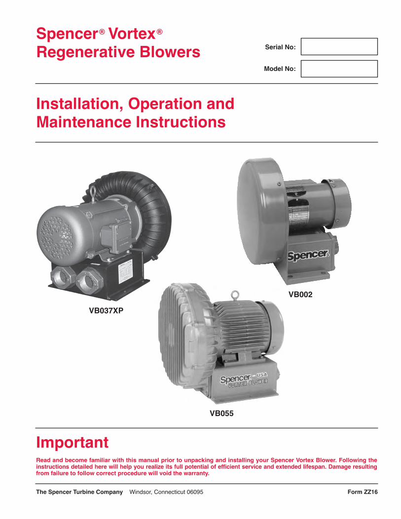
VB037XP
VB055
Spencer® Vortex®
Regenerative Blowers
Installation, Operation andMaintenance Instructions
VB002

ContentsI. General Page
Scope . . . . . . . . . . . . . . . . . . . . . . . . . . . . . . . . . 2Limited Warranty . . . . . . . . . . . . . . . . . . . . . . . . . 2Safety Precautions . . . . . . . . . . . . . . . . . . . . . . . 2
II. InstallationLocating, Mounting, Connecting . . . . . . . . . . . . . 2Wiring . . . . . . . . . . . . . . . . . . . . . . . . . . . . . . . . . 3
III. OperationLimits of Operation . . . . . . . . . . . . . . . . . . . . . 4-5Temperature Rise . . . . . . . . . . . . . . . . . . . . . . . . 5
IV. Disassembly and ReassemblyGeneral . . . . . . . . . . . . . . . . . . . . . . . . . . . . . . . . 5Disassembly Procedure . . . . . . . . . . . . . . . . . . . 5Reassembly Cautions . . . . . . . . . . . . . . . . . . . . . 5Locknut Torque . . . . . . . . . . . . . . . . . . . . . . . . . . 6
V. Vortex Blower DataAssembly Diagrams . . . . . . . . . . . . . . . . . . . . 6-17Parts Lists . . . . . . . . . . . . . . . . . . . . . . . . . . . 6-17Performance Curves . . . . . . . . . . . . . . . . . . . 6-17
VI. Troubleshooting Guide . . . . . . . . . . . . . . . . . . . . . 18
I. GeneralScopeInformation contained in this manual relates to VortexBlowers standard and explosion-proof motor modelsVB001S, VB001, VB002S, VB002, VB003S, VB003,VB004S, VB004, VB007S, VB007, VB019S, VB019,VB030S, VB030, VB037S, VB037, VB055, VB075, andVB110.
Limited WarrantyWe warrant that this product will be free from defects inmaterial and workmanship for a period of 18 months fromdate of shipment or 12 months from date of startup,whichever comes first. Within the warranty period, weshall repair or replace F.O.B. our Factory such productsthat are determined by us to be defective.
This warranty will not apply to any product which has beensubjected to misuse, negligence, or accident, or misap-plied or improperly installed. This warranty will not applyto any product which has been disassembled, repaired, orotherwise altered by any persons not authorized by theSpencer Vortex Service Department.
On units which include thermal protection, the thermalprotection must be connected as recommended.
The guarantee of the motor and control manufacturerswill govern the extent of our guarantee on such equip-ment. Warranty work on motors and controls must beauthorized by Spencer and must be performed in anauthorized shop as designated by the manufacturers.
The Spencer Turbine Company reserves the right toinvoice all expenses incurred when repairs are made inthe field at the specific request of the customer.
No assemblies or parts of assemblies will be accepted forrepair or replacement under this warranty without priorauthorization by The Spencer Turbine Company. Forcomplete warranty information, obtain Spencerʼs Form 706,“Terms and Conditions of Sales.”
Safety PrecautionsPower sources, protective devices, and grounding provi-sions must be in accordance with wiring instructionsprovided in this manual.
Blower becomes hot during operation and may causeburns if touched.
Do not operate the blower under load conditions whichexceed the rated full-load amps on the nameplate.
Do not install the blower in any area which may have anexplosive atmosphere or which may contain flammablegases or liquids. Always provide proper ventilation. Donot install in any area which may subject the blower tocorrosive liquids. Excessive moisture may cause electri-cal failure; install the blower in areas free from water orrain. Do not operate blower without motor cooling fancover, or without impeller end cover.
Before installing blowers with explosion-proof motors,the buyer must check federal, state and local codes tosee if such motors are appropriate for the intended appli-cation environment. It is the buyerʼs responsibility todetermine the suitability of any product for a particularpurpose.
StorageIf machine is to be stored for an extended period of time,it must be carefully protected from dampness and dirt.
II. InstallationLocating, Mounting, ConnectingAmbient temperature at the installed location should notbe less than -5˚ F or greater than 104˚ F. Relative humidityshould not exceed 80%.
Mount the blower in a horizontal or vertical position asshown in Figure 1. For models VB055, VB075 andVB110, it is recommended to mount in the horizontalposition only. Check with factory prior to mountingthese models vertically.
Fig. 1 Mounting Positions
Remove protective coverings, such as vinyl tape orplastic plugs, from the inlet and outlet ports. ModelsVB001, VB002 and VB003 are supplied with a patented(U.S. Patent 5,791,870) reversible flange with threadedpipe or tubing connections. Avoid excessive stress causedby pipe connector tightening or by misaligned pipe onthe inlet and outlet ports. Support piping by brackets orother means.2

In the event the blower is located where dust, fibers,drops of water, or other particulates may be in theairstream, use a filter on the suction side of the piping. Ifforeign matter enters the impeller, it may clog, jam, orotherwise impair the blower performance.
WiringCaution: Confirm that the power source is the sameas that indicated on the unitʼs nameplate. Applicationof incorrect voltage or improper phase connectionmay cause motor failure or other damage.
Use conductors and devices (such as the circuitbreakers, starters, and switches shown in Figure 3)that are suitable for the applications shown in Tables1 and 2 and are in compliance with the NationalElectric Code and applicable local codes and regula-tions. Motor terminal connections are shown belowTable 1.
Provide protection from overheating of the motorwindings. Some models are equipped with built-inthermal protectors (see Table 1). Where applicable,connect the leads from the pilot-duty thermal protectorto the magnetic starter as shown in Fig. 3.
Check the direction of rotation of the blower.To reverse the direction or rotation:1) for a single-phase motor, interchange motor
leads 5 and 8.2) for a three-phase motor, interchange any two of
the three line connections.
Caution: Install a properly-sized overload device anddisconnect in accordance with local codes and regu-lations and dedicated only to the Vortex Blower.
Furnish the Vortex Blower and all associated electricaldevices with a proper ground in accordance withall local codes and regulations.
3
Fig. 3 Typical Wiring Diagram
The Spencer Turbine Company � 600 Day Hill Road, Windsor, CT 06095 � TEL 800-232-4321 � 860-688-8361 � www.spencerturbine.com

Model No.Power (hp)Voltage (V)FL Amps (A)
VB001S0.13
110/2201.34/.67
VB002S0.21
110/2202.1/1.05
VB003S0.5
110/2205.6/2.8
VB004S0.63
100-110/2209.9-11.6/5.8
VB007S1.25
110/22015.4/7.7
VB019S2.1
100-110/22022-21/10.5
VB030S3.3
100-110/22042-38.6/19.3
VB037S4.222019
Model No.Power (hp)Voltage (V)FL Amps (A)
VB001S0.13
115/2301.25/.63
VB002S0.25
115/2302.3/1.15
VB003S0.5
115/2305.2/2.6
VB004S0.75
115/208-2309.6/5-4.8
VB007S1.5
115/208-23013.4/6.7
VB019S2.5
115/208-23022/11.5-11
VB030S4
115/208-23034.8/18.5-17.4
VB037S5
23020.8
4The Spencer Turbine Company � 600 Day Hill Road, Windsor, CT 06095 � TEL 800-232-4321 � 860-688-8361 � www.spencerturbine.com
5
1
4
8
Line
60 Hertz Operation
50 Hertz Operation
Table 2 Single-Phase Motor Data - Typical Values
NOTES: (1) For three-phase, interchange any two line connections to reverse shaft rotation(2) For single-phase, interchange motor leads 5 and 8 to reverse shaft rotation
MOTOR WIRING CW RotationThree-Phase
Low Voltage High VoltageSingle-Phase
Low Voltage High Voltage
THERMOSTATSVB004 AND LARGER
Volts Amps
Line Line Line Line
Model No.Power (hp)Voltage (V)FL Amp (A)Voltage (V)FL Amp (A)
VB0010.13
200-230/460.5-.48/.24
VB0020.25
200-230/460.86-.73/.37
575.4
VB0030.5
208-230/4601.8-1.6/.8
5750.8
VB0040.75
200-230/4602.3-2.4/1.2
5750.96
VB0071.5
200-230/4604.3-4/2
5751.4
VB0192.5
200-230/4607.2-6.6/3.3
5752.1
Table 1 Three-Phase Motor Data - Typical Values60 Hertz Operation
Model No.Power (hp)Voltage (V)FL Amp (A)Voltage (V)FL Amp (A)
VB0304
200-230/46010.6-10.2/5.1
5753
VB0375
200-230/46013.2-12/6
5754.8
VB0557.5
200-230/46019.8-17.2/8.6
5757
VB07510
200-230/46027.5-27.2/13.6
5759.6
VB11015
200-230/46039-37/18.5
57513.5
——————
50 Hertz Operation
Model No.Power (hp)Voltage (V)FL Amp (A)
VB0303.4
190/380-41510.2/5.2-5.1
VB0374.2
190/380-41511.8/5.9-5.6
VB0556.25
190/380-41517.6/8.8-8.2
VB0758.33
190/380-41527/13.5-14.5
VB11012.5
190/380-41536/18-17
————
Wiring
NOTE: Thermostats are provided on the VB004 and larger models.
Model No.Power (hp)Voltage (V)FL Amp (A)
VB0010.13
190-220/380-415.5-.52/.25-.26
VB0020.21
190-220/380-415.74-.66/.37-.34
VB0030.5
190/380-4152/1-.9
VB0040.63
190/380-4152.4/1.2-1.3
VB0071.25
190/380-4154/2
VB0192.1
190/380-4156.6/3.3-3.1
VB037230V
Single-PhaseSingle Voltage

5
Fig. 4 Typical Nameplate
III. OperationLimits of OperationOperation at flows less than those indicated by the solidline on the applicable performance curve will causeoverheating of the unit and is to be avoided. Throttlingsuction or discharge piping to reduce air volumeincreases differential pressure resulting in elevatedtemperature and increased power consumption. Useof pressure and/ or vacuum relief valve recommended.
Maximum pressure and vacuum are indicated on thenameplate (see Fig. 4). These represent conditions atwhich the minimum allowable airflow (CFM) occurs.Check the operating pressure or vacuum to assure thatthe pressure or vacuum remains less than maximum.
For continuous operation at low air volume (on thedotted portion of the performance curve), provide abypass in the piping and operate at a lower pressurethan maximum operating pressure. See PerformanceCurves, Section V.
Caution: Low flow conditions may produce heat levelswhich may cause burns. Do not touch the blower inoperation.
Temperature RiseA NEMA Class F insulation system is used in the motor.Maximum allowable winding temperature is 265˚F. If athermal protector or thermal relay activates because thetemperature rise of the motor is higher than usual, inves-tigate and correct the problem. Explosion-proof motorsuse a NEMA Class B insulation. Typical causes of motoroverheating are given in Section VI, TroubleshootingGuide.
IV. Disassembly andReassembly
A. General1. Precautions should be taken when disassembling
or reassembling the blower. See Warranty Terms.2. Keep all parts clean.3. Do not overtighten bolts and screws.
Fig. 5 Impeller Puller
B. Disassembly Procedure (Reassembly is performedin reverse order)
Caution: Shims are used to adjust the gap betweenthe impeller and casing. When disassembling,take care to note the quantity of shims and theirthickness. The shim stack replacement must bethe correct thickness to assure proper clearanceand to avoid degradation of performance.
1. Remove impeller cover; remove screws, pull coveraway from case.
2. Unfasten lock washer; remove nut and washer.3. Remove impeller from shaft by one of the following
methods:a. manually pull the impeller outward, ORb. screw two bolts into tapped holes and pull on
the bolts, OR (if the fit is tight)c. use a puller assembly (not furnished) as shown in
Fig. 5.4. Remove motor shaft key.5. Remove case from motor; if necessary remove
screws holding case to base and motor to case.6. Remove shims from motor shaft if necessary; do
not discard them. See Note above.
Caution: Motors are heavy. Lift motor on modelslarger than VB002 by the eyebolt on the motor withan aid from a lifting device.
C. Reassembly Guidance1. The gap between the impeller and case is essential for
proper performance of the unit. The shims betweenthe shaft collar and impeller hub establish the spacingof this gap. In reassembly, before installing theimpeller cover, check the gap between the impellerand case to assure that the measurement conforms tothe gap specification on the assembly drawing (on thefollowing pages) for your unit.
The Spencer Turbine Company � 600 Day Hill Road, Windsor, CT 06095 � TEL 800-232-4321 � 860-688-8361 � www.spencerturbine.com
Year of Production THREADEDPLATE
SHIM BLOCK
MOTOR“C” FACE IMPELLER
HUBSHAFT
BOLT

6
2. For models VB001, VB002 and VB003, gap clearancebetween impeller and unibody case should bechecked around entire periphery of the impeller inaccordance with Item 18, impeller to case gap specifi-cation prior to securing impeller.
3 On models VB004 thru VB110 remove Item 23 Pluglocated on bottom of the case and check impeller gapwith a feeler gauge. Remove impeller and adjustshims to meet gap specification. With adjustments andgap check complete, replace plug tightly to prevent airleakage.
4. Fasten impellers using lockwashers and locknuts.Torgue locknut to recommended torque values inTable 3. Bend a lockwasher tab down into a lockwash-er slot.
5. Reattach the impeller cover.
V. Vortex Blower DataPages 7 through 17 present information about thevarious blower models. This information is importantin understanding your blowerʼs performance, in usingthe blower in the proper operating range, and in orderingparts that might be needed.
A. Assembly DiagramsAt the top of each page is an assembly diagram of theunit. Items are identified by circled numbers around thediagram. Above each diagram is the gap specification.
B. Parts ListsAt the lower left of each diagram is a table giving theitem number (shown on the Assembly Diagram), thePart No. for that item and the corresponding partdescription. In ordering parts, provide the modelnumber, the part number and the description.
C. Performance CurvesAt the lower right of each diagram are performancecurves for 50Hz and 60Hz operation. The curvespresent the following information:
The upper line of each curve is pressure performancewhile the lower line is vacuum performance. Thedashed portion at the left end of some of the curvesindicates an intermittent-only operating area. SeeOperation Section on page 5.
D. Estimated Acoustical Noise Level at 1.5M, 60Hz
Model dbaVB001S 62VB001 61VB002S 61VB002 61VB003S 66VB003 66VB004S 63VB004 63VB007S 70VB007 64VB019S 70VB019 73VB030S 71VB030 73VB037S 74VB037 76VB055 82VB075 81VB110 80
Table 3 Locknut Torque
The Spencer Turbine Company � 600 Day Hill Road, Windsor, CT 06095 � TEL 800-232-4321 � 860-688-8361 � www.spencerturbine.com
VB001, VB001S, VB002VB002S, VB003, VB003S
VB004, VB004S
VB007, VB007S
VB019, VB019S
VB030, VB030S
VB037, VB037S
VB055
VB075
VB110
22
31
36
36
44
44
77
90
90
Catalog No. RecommendedTorque (Ft-Lb)

7
Performance Curves
Parts List
Spencer® Vortex® Regenerative BlowersVB001S, VB001
The Spencer Turbine Company � 600 Day Hill Road, Windsor, CT 06095 � TEL 800-232-4321 � 860-688-8361 � www.spencerturbine.com
DESCRIPTION: VORTEX BLOWER ASSEMBLY – VB001S & VB001ITEM PART NO. DESCRIPTION QTY.
1 VBC90101 Case, Unibody 12 VBI90101 Impeller 13 VBE90101 Cover, Impeller 14 NUT90219 Locknut, Shaft 15 WSH90184 Lockwasher, Shaft 16 WSH90185 Shim, Shaft to Impeller (as required) 17 MOT90210 Motor 42C, 1/8 HP, 1PH, 50/60Hz 1
7A MOT90215 Motor 42C, 1/8 HP, 3PH, 50/60Hz 18 SCR90901 M4 x 0.7 Pan Head Phillips Screw x .31 [8] Long 410 SCR90307 1/4-20 x .625" Long Socket Cap Screw 411 GSK90168 Gasket, Flange 112 FLC90013 Flange 113 SCR90888 M5 x 0.8 Hex Head Bolt x .63 [16] long 616 INS90014 Absorber 217 KEY90083 Key 118 N/A Impeller to case gap specification N/A
Assembly Diagram
in. mm.
VB001S, VB001

8
Performance Curves
The Spencer Turbine Company � 600 Day Hill Road, Windsor, CT 06095 � TEL 800-232-4321 � 860-688-8361 � www.spencerturbine.com
Spencer® Vortex® Regenerative BlowersVB002S, VB002
Parts ListDESCRIPTION: VORTEX BLOWER ASSEMBLY – VB002S & VB002ITEM PART NO. DESCRIPTION QTY.
1 VBC90201 Case, Unibody 12 VBI90201 Impeller 13 VBE90201 Cover, Impeller 14 NUT90219 Locknut, Shaft 15 WSH90184 Lockwasher, Shaft 16 WSH90185 Shim, Shaft to Impeller (as required) 17 MOT90211 Motor 42C, 1/4 HP, 1PH, 50/60Hz 1
7A MOT90212 Motor 42C, 1/4 HP, 3PH, 50/60Hz 18 SCR90901 M4 x 0.7 Pan Head Phillips Screw x .31 [8] Long 410 SCR90307 1/4-20 x .625" Long Socket Cap Screws 411 GSK90169 Gasket, Flange 112 FLC90014 Flange 113 SCR90888 M5 x 0.8 Hex Head Bolt x .63 [16] Long 616 INS90015 Absorber 217 KEY90085 Key 118 N/A Impeller to case gap specification N/A
Assembly Diagram
in. mm.
VB002S, VB002
9
Performance Curves
The Spencer Turbine Company � 600 Day Hill Road, Windsor, CT 06095 � TEL 800-232-4321 � 860-688-8361 � www.spencerturbine.com
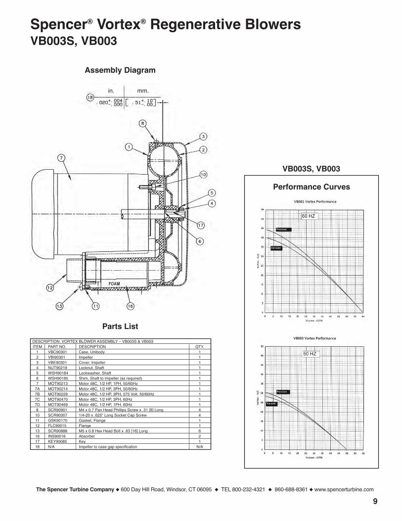
Spencer® Vortex® Regenerative BlowersVB003S, VB003
Assembly Diagram
Parts ListDESCRIPTION: VORTEX BLOWER ASSEMBLY – VB003S & VB003ITEM PART NO. DESCRIPTION QTY.
1 VBC90301 Case, Unibody 12 VBI90301 Impeller 13 VBE90301 Cover, Impeller 14 NUT90219 Locknut, Shaft 15 WSH90184 Lockwasher, Shaft 16 WSH90185 Shim, Shaft to Impeller (as required) 17 MOT90213 Motor 48C, 1/2 HP, 1PH, 50/60Hz 1
7A MOT90214 Motor 48C, 1/2 HP, 3PH, 50/60Hz 17B MOT90229 Motor 48C, 1/2 HP, 3PH, 575 Volt, 50/60Hz 17C MOT90470 Motor 48C, 1/2 HP, 3PH, 60Hz 17D MOT90469 Motor 48C, 1/2 HP, 1PH, 60Hz 18 SCR90901 M4 x 0.7 Pan Head Phillips Screw x .31 [8] Long 410 SCR90307 1/4-20 x .625" Long Socket Cap Screw 411 GSK90170 Gasket, Flange 112 FLC90015 Flange 113 SCR90888 M5 x 0.8 Hex Head Bolt x .63 [16] Long 616 INS90016 Absorber 217 KEY90085 Key 118 N/A Impeller to case gap specification N/A
in. mm.
VB003S, VB003

10
Performance Curves
The Spencer Turbine Company � 600 Day Hill Road, Windsor, CT 06095 � TEL 800-232-4321 � 860-688-8361 � www.spencerturbine.com
Spencer® Vortex® Regenerative BlowersVB004S, VB004
Assembly Diagram
Parts ListDESCRIPTION: VORTEX BLOWER ASSEMBLY – VB004S & VB004ITEM PART NO. DESCRIPTION QTY.
1 VBC90401 Case 12 VBI90401 Impeller 13 VBB90401 Base 14 VBE90401 Cover, Impeller 15 NUT90212 Locknut, Shaft 16 WSH90170 Lockwasher, Shaft 17 WSH90177 Shim, Shaft to Impeller (as required) 18 MOT90193 Motor 48C, 3/4 HP, 1PH, 50/60Hz 1
8A MOT90192 Motor 48C, 3/4 HP, 3PH, 50/60Hz 18B MOT90230 Motor 48C, 3/4 HP, 3PH, 575 Volt, 50/60Hz 18C MOT90471 Motor 48C, 3/4 HP, 3PH, 60Hz 18D MOT90472 Motor 48C, 3/4 HP, 1PH, 60Hz 19 SCR90887 M6 x 1.0 Hex Head Bolt x .63 [16] Long 410 WSH90142 Lock washer, M5 411 WSH90166 Flat Washer, M5 412 SCR90888 M5 x 0.8 Hex Head Bolt x .63 [16] Long 213 WSH90181 Flat Washer, M5 214 SCR90877 M5 x 0.8 Pan Head Phillips Screw x .39 [10] Long 415 WSH90138 Lockwasher, M5 416 WSH90139 Flat Washer, M5 417 SCR90307 1/4-20 x .625" Long Socket Cap screw 418 GSK90165 Gasket, Case 119 GSK90163 Gasket, Flange 220 FLC90007 Flange 221 SCR90931 M6 x 1.0 S.H.C.S. x .98 [25] Long 423 PLG90037 Plug, 1/4 NPT x .43 [11] Long 125 INS90017 Absorber 426 SCN90065 Screen 227 KEY90076 Key 128 SEL90108 Lip Seal 129 N/A Impeller to case gap specification N/A
VB004S, VB004
Impeller Gap Port
29mm.
.020 +.002 [.51 +.05]
in.
11The Spencer Turbine Company � 600 Day Hill Road, Windsor, CT 06095 � TEL 800-232-4321 � 860-688-8361 � www.spencerturbine.com
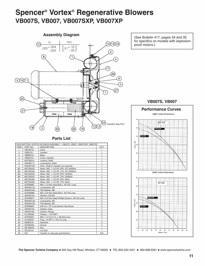
Spencer® Vortex® Regenerative BlowersVB007S, VB007, VB007SXP, VB007XP
Performance Curves
(See Bulletin 417, pages 34 and 35for specifics on models with explosion-proof motors.)
Assembly Diagram
VB007S, VB007
Impeller Gap Port
Parts ListDESCRIPTION: VORTEX BLOWER ASSEMBLY – VB007S, VB007, VB007SXP, VB007XPITEM PART NO. DESCRIPTION QTY.
1 VBC90701 Case 12 VBI90701 Impeller 13 VBB90701 Base 14 VBE90701 Cover, Impeller 15 NUT90210 Locknut, Shaft 16 WSH90171 Lockwasher, Shaft 17 WSH90160 Shim, Shaft to Impeller (as required) 1
8C MOT90225 Motor, 56C, 1-1/2 HP, 3PH, XP, 50/60Hz 18D MOT90358 Motor, 56C, 1-1/2 HP, 1PH, XP, 50/60Hz 18G MOT90248 Motor, 56C, 1-1/2 HP, 3PH, 50/60Hz 18H MOT90253 Motor, 56C, 1-1/2 HP, 1PH, 50/60Hz 18I MOT90485 Motor, 56C, 1-1/2 HP, 3PH, 60Hz 18J MOT90484 Motor, 56C, 1-1/2 HP, 1PH, 60Hz 19 SCR90887 M6 x 1.0 Hex Head Bolt x .63 [16] Long 410 WSH90142 Lockwasher, M6 411 WSH90166 Flat Washer, M6 412 SCR90888 M5 x 0.8 Hex Head Bolt x .63 [16] Long 213 WSH90181 Washer, Flat M5 214 SCR90877 M5 x 0.8 Pan Head Phillips Screw x .39 [10] Long 415 WSH90138 Lockwasher, M5 416 WSH90139 Flat Washer, M5 417 SCR90867 3/8-16 x .75" Long Socket Cap Screw 418 GSK90164 Gasket, Case 119 GSK90163 Gasket, Flange 220 FLC90008 Flange, 1 1/2 FNPT 221 SCR90931 M6 x 1.0 S.H.C.S. x .98 [25] Long 423 PLG90037 Plug, 1/4 NPT x .43 [11] Long 125 INS90018 Absorber 426 SCN90064 Screen 227 KEY90076 Key 128 SEL90107 Lip Seal 130 N/A Impeller to case gap specification N/A
[.51
in. mm.30
+.004-.002
.020 +.10-.05 ]
12
Performance Curves
The Spencer Turbine Company � 600 Day Hill Road, Windsor, CT 06095 � TEL 800-232-4321 � 860-688-8361 � www.spencerturbine.com
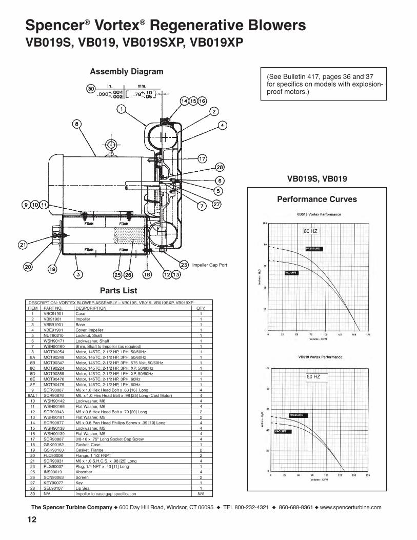
Spencer® Vortex® Regenerative BlowersVB019S, VB019, VB019SXP, VB019XP
(See Bulletin 417, pages 36 and 37for specifics on models with explosion-proof motors.)
Assembly Diagram
Parts ListDESCRIPTION: VORTEX BLOWER ASSEMBLY – VB019S, VB019, VB019SXP, VB019XPITEM PART NO. DESPCRIPTION QTY.
1 VBC91901 Case 12 VBI91901 Impeller 13 VBB91901 Base 14 VBE91901 Cover, Impeller 15 NUT90210 Locknut, Shaft 16 WSH90171 Lockwasher, Shaft 17 WSH90160 Shim, Shaft to Impeller (as required) 18 MOT90254 Motor, 145TC, 2-1/2 HP, 1PH, 50/60Hz 1
8A MOT90249 Motor, 145TC, 2-1/2 HP, 3PH, 50/60Hz 18B MOT90347 Motor, 145TC, 2-1/2 HP, 3PH, 575 Volt, 50/60Hz 18C MOT90224 Motor, 145TC, 2-1/2 HP, 3PH, XP, 50/60Hz 18D MOT90359 Motor, 145TC, 2-1/2 HP, 1PH, XP, 50/60Hz 18E MOT90476 Motor, 145TC, 2-1/2 HP, 3PH, 60Hz 18F MOT90475 Motor, 145TC, 2-1/2 HP, 1PH, 60Hz 19 SCR90887 M6 x 1.0 Hex Head Bolt x .63 [16] Long 4
9ALT SCR90876 M6. x 1.0 Hex Head Bolt x .98 [25] Long (Cast Motor) 410 WSH90142 Lockwasher, M6 411 WSH90166 Flat Washer, M6 412 SCR90943 M5 x 0.8 Hex Head Bolt x .79 [20] Long 213 WSH90181 Flat Washer, M5 214 SCR90877 M5 x 0.8 Pan Head Phillips Screw x .39 [10] Long 415 WSH90138 Lockwasher, M5 416 WSH90139 Flat Washer, M5 417 SCR90867 3/8-16 x .75" Long Socket Cap Screw 418 GSK90162 Gasket, Case 119 GSK90163 Gasket, Flange 220 FLC90008 Flange, 1 1/2 FNPT 221 SCR90931 M6 x 1.0 S.H.C.S. x .98 [25] Long 423 PLG90037 Plug, 1/4 NPT x .43 [11] Long 125 INS90019 Absorber 426 SCN90063 Screen 227 KEY90077 Key 128 SEL90107 Lip Seal 130 N/A Impeller to case gap specification N/A
VB019S, VB019
Impeller Gap Port

13
Performance Curves
The Spencer Turbine Company � 600 Day Hill Road, Windsor, CT 06095 � TEL 800-232-4321 � 860-688-8361 � www.spencerturbine.com
Spencer® Vortex® Regenerative BlowersVB030S, VB030, VB030XP
(See Bulletin 417, pages 38 and 39for specifics on models with explosion-proof motors.)
Assembly Diagram
Parts ListDESCRIPTION: VORTEX BLOWER ASSEMBLY – VB030S, VB030, VB030XPITEM PART NO. DESCRIPTION QTY.
1 VBC93001 Case 12 VBI93001 Impeller 13 VBB93001 Base 14 VBE93001 Cover, Impeller 15 NUT90209 Locknut, Shaft 16 WSH90172 Lockwasher, Shaft 17 WSH90157 Shim, Shaft to Impeller (as required) 18 MOT90370 Motor, 184TC, 4 HP, 1PH, 50/60Hz 1
8A MOT90250 Motor, 182TC, 4 HP, 3PH, 50/60Hz 18B MOT90348 Motor, 182TC, 4 HP, 3PH, 575 Volt, 50/60Hz 18C MOT90223 Motor, 182TC, 4 HP, 3PH, XP, 50/60Hz 18D MOT90478 Motor, 182TC, 4 HP, 3PH, 60Hz 18E MOT90477 Motor, 182TC, 4 HP, 1PH, 60Hz 19 SCR90879 M8 x 1.25 Hex Head Bolt x .98 [25] Long 410 WSH90148 Lockwasher, M8 411 WSH90182 Flat Washer, M8 412 SCR90876 M6 x 1.0 Hex Head Bolt x .98 [25] Long 213 WSH90166 Flat Washer, M6 214 SCR90877 M5 x 0.8 Pan Head Phillips Screw x .39 [10] Long 415 WSH90138 Lockwasher, M5 416 WSH90139 Flat Washer, M5 417 SCR90335 1/2 -13 x 1.0 Long Socket Cap Screw 418 GSK90161 Gasket, Case 119 GSK90155 Gasket, Flange 220 FLC90009 Flange, 2 FNPT 221 SCR90878 M6 x 1.0 Hex Head Bolt x 1.57 [40] Long 423 PLG90037 Plug, 1/4 NPT x .43 [11] Long 125 INS90020 Absorber 426 SCN90062 Screen 227 KEY90078 Key 128 SEL90104 Lip Seal 130 N/A Impeller to case gap specification N/A
VB030S, VB030
Impeller Gap Port
14
Performance Curves
The Spencer Turbine Company � 600 Day Hill Road, Windsor, CT 06095 � TEL 800-232-4321 � 860-688-8361 � www.spencerturbine.com
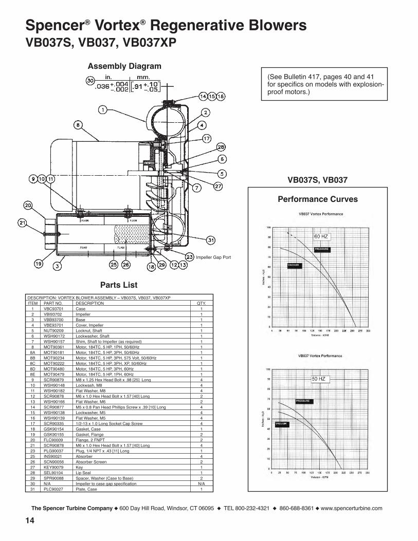
Spencer® Vortex® Regenerative BlowersVB037S, VB037, VB037XP
(See Bulletin 417, pages 40 and 41for specifics on models with explosion-proof motors.)
Assembly Diagram
Parts ListDESCRIPTION: VORTEX BLOWER ASSEMBLY – VB037S, VB037, VB037XPITEM PART NO. DESCRIPTION QTY.
1 VBC93701 Case 12 VBI93702 Impeller 13 VBB93700 Base 14 VBE93701 Cover, Impeller 15 NUT90209 Locknut, Shaft 16 WSH90172 Lockwasher, Shaft 17 WSH90157 Shim, Shaft to Impeller (as required) 18 MOT90361 Motor, 184TC, 5 HP, 1PH, 50/60Hz 1
8A MOT90181 Motor, 184TC, 5 HP, 3PH, 50/60Hz 18B MOT90234 Motor, 184TC, 5 HP, 3PH, 575 Volt, 50/60Hz 18C MOT90222 Motor, 184TC, 5 HP, 3PH, XP, 50/60Hz 18D MOT90480 Motor, 184TC, 5 HP, 3PH, 60Hz 18E MOT90479 Motor, 184TC, 5 HP, 1PH, 60Hz 19 SCR90879 M8 x 1.25 Hex Head Bolt x .98 [25] Long 410 WSH90148 Lockwash, M8 411 WSH90182 Flat Washer, M8 412 SCR90878 M6 x 1.0 Hex Head Bolt x 1.57 [40] Long 213 WSH90166 Flat Washer, M6 214 SCR90877 M5 x 0.8 Pan Head Phillips Screw x .39 [10] Long 415 WSH90138 Lockwasher, M5 416 WSH90139 Flat Washer, M5 417 SCR90335 1/2-13 x 1.0 Long Socket Cap Screw 418 GSK90154 Gasket, Case 119 GSK90155 Gasket, Flange 220 FLC90009 Flange, 2 FNPT 221 SCR90878 M6 x 1.0 Hex Head Bolt x 1.57 [40] Long 423 PLG90037 Plug, 1/4 NPT x .43 [11] Long 125 INS90021 Absorber 426 SCN90056 Absorber Screen 227 KEY90079 Key 128 SEL90104 Lip Seal 129 SPR90088 Spacer, Washer (Case to Base) 230 N/A Impeller to case gap specification N/A31 PLC90027 Plate, Case 1
VB037S, VB037
Impeller Gap Port
15
Performance Curves
The Spencer Turbine Company � 600 Day Hill Road, Windsor, CT 06095 � TEL 800-232-4321 � 860-688-8361 � www.spencerturbine.com
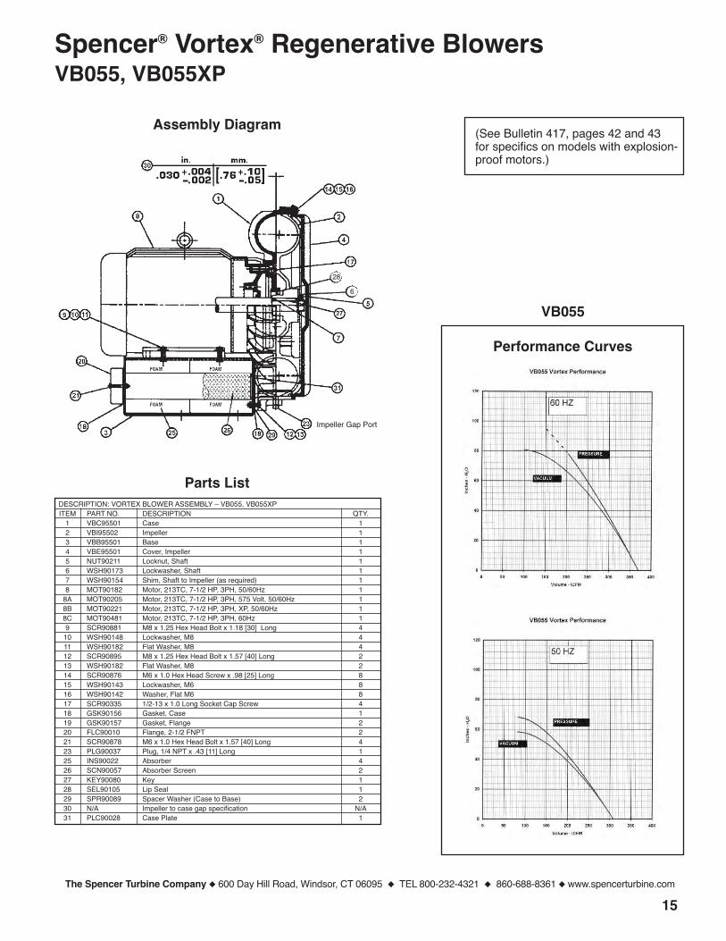
Spencer® Vortex® Regenerative BlowersVB055, VB055XP
(See Bulletin 417, pages 42 and 43for specifics on models with explosion-proof motors.)
Assembly Diagram
Parts ListDESCRIPTION: VORTEX BLOWER ASSEMBLY – VB055, VB055XPITEM PART NO. DESCRIPTION QTY.
1 VBC95501 Case 12 VBI95502 Impeller 13 VBB95501 Base 14 VBE95501 Cover, Impeller 15 NUT90211 Locknut, Shaft 16 WSH90173 Lockwasher, Shaft 17 WSH90154 Shim, Shaft to Impeller (as required) 18 MOT90182 Motor, 213TC, 7-1/2 HP, 3PH, 50/60Hz 1
8A MOT90205 Motor, 213TC, 7-1/2 HP, 3PH, 575 Volt, 50/60Hz 18B MOT90221 Motor, 213TC, 7-1/2 HP, 3PH, XP, 50/60Hz 18C MOT90481 Motor, 213TC, 7-1/2 HP, 3PH, 60Hz 19 SCR90881 M8 x 1.25 Hex Head Bolt x 1.18 [30] Long 410 WSH90148 Lockwasher, M8 411 WSH90182 Flat Washer, M8 412 SCR90895 M8 x 1.25 Hex Head Bolt x 1.57 [40] Long 213 WSH90182 Flat Washer, M8 214 SCR90876 M6 x 1.0 Hex Head Screw x .98 [25] Long 815 WSH90143 Lockwasher, M6 816 WSH90142 Washer, Flat M6 817 SCR90335 1/2-13 x 1.0 Long Socket Cap Screw 418 GSK90156 Gasket, Case 119 GSK90157 Gasket, Flange 220 FLC90010 Flange, 2-1/2 FNPT 221 SCR90878 M6 x 1.0 Hex Head Bolt x 1.57 [40] Long 423 PLG90037 Plug, 1/4 NPT x .43 [11] Long 125 INS90022 Absorber 426 SCN90057 Absorber Screen 227 KEY90080 Key 128 SEL90105 Lip Seal 129 SPR90089 Spacer Washer (Case to Base) 230 N/A Impeller to case gap specification N/A31 PLC90028 Case Plate 1
VB055
Impeller Gap Port
28
6

16
Performance Curves
The Spencer Turbine Company � 600 Day Hill Road, Windsor, CT 06095 � TEL 800-232-4321 � 860-688-8361 � www.spencerturbine.com
Spencer® Vortex® Regenerative BlowersVB075, VB075XP
Assembly Diagram
Parts ListDESCRIPTION: VORTEX BLOWER ASSEMBLY – VB075, VB075XPITEM PART NO. DESCRIPTION QTY.
1 VBC97501 Case 12 VBI97502 Impeller 13 VBB97501 Base 14 VBE97501 Cover, Impeller 15 NUT90213 Locknut, Shaft 16 WSH90174 Lockwasher, Shaft 17 WSH90179 Shim, Shaft to Impeller (as required) 18 MOT90199 Motor, 215TC, 10 HP, 3PH, 50/60Hz 1
8A MOT90235 Motor, 215TC, 10 HP, 3PH, 575 Volt, 50/60Hz 18B MOT90220 Motor, 215TC, 10 HP, 3PH, XP, 50/60Hz 18C MOT90482 Motor, 215TC, 10 HP, 3PH, 60Hz 19 SCR90881 M8 x 1.25 Hex Head Bolt x 1.18 [30] Long 410 WSH90148 Lockwasher, M8 411 WSH90182 Flat Washer M8 412 SCR90881 M8 x 1.25 Hex Head Bolt x 1.18 [30] Long 213 WSH90182 Flat Washer M8 214 SCR90876 M6 x 1.0 Hex Head Screw x .98 [25] Long 815 WSH90143 Lockwasher, M6 816 WSH90142 Flat Washer M6 817 SCR90335 1/2-13 x 1.0 Long Socket Cap Screw 418 GSK90158 Gasket, Case 119 GSK90159 Gasket, Flange 220 FLC90011 Flange, 3 FNPT 221 SCR90883 M8 x 1.25 Hex Head Bolt x 2.165 [55] Long 423 PLG90037 Plug, 1/4 NPT x .43 [11] Long 125 INS90023 Absorber 426 SCN90058 Absorber Screen 227 KEY90081 Key 128 SEL90106 Lip Seal 129 SPR90089 Spacer, Washer (Case to Base) 230 N/A Impeller to case gap specification N/A31 PLC90029 Case Plate 1
VB075
(Contact factory for specifics onmodels with explosion-proof motor.)
Impeller Gap Port
30in. mm.
+.004-.002
.86.034 + .10- .05[ ]
17
Performance Curves
The Spencer Turbine Company � 600 Day Hill Road, Windsor, CT 06095 � TEL 800-232-4321 � 860-688-8361 � www.spencerturbine.com
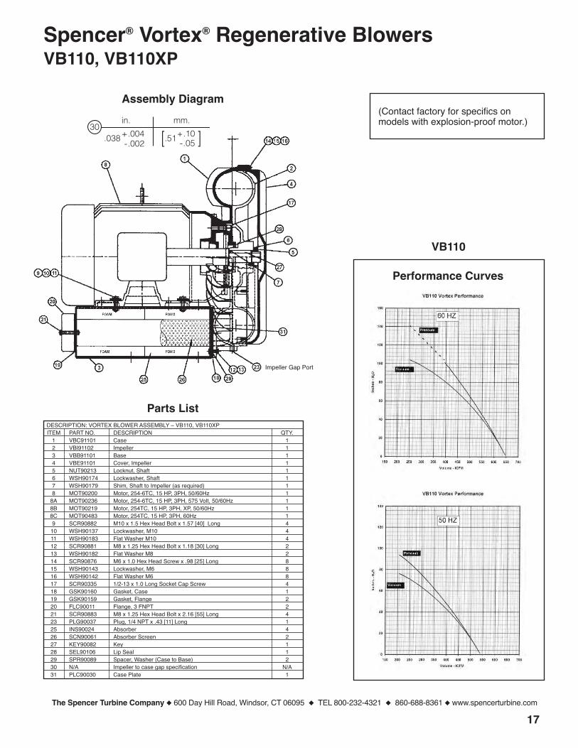
Spencer® Vortex® Regenerative BlowersVB110, VB110XP
Assembly Diagram
Parts ListDESCRIPTION: VORTEX BLOWER ASSEMBLY – VB110, VB110XPITEM PART NO. DESCRIPTION QTY.
1 VBC91101 Case 12 VBI91102 Impeller 13 VBB91101 Base 14 VBE91101 Cover, Impeller 15 NUT90213 Locknut, Shaft 16 WSH90174 Lockwasher, Shaft 17 WSH90179 Shim, Shaft to Impeller (as required) 18 MOT90200 Motor, 254-6TC, 15 HP, 3PH, 50/60Hz 1
8A MOT90236 Motor, 254-6TC, 15 HP, 3PH, 575 Volt, 50/60Hz 18B MOT90219 Motor, 254TC, 15 HP, 3PH, XP, 50/60Hz 18C MOT90483 Motor, 254TC, 15 HP, 3PH, 60Hz 19 SCR90882 M10 x 1.5 Hex Head Bolt x 1.57 [40] Long 410 WSH90137 Lockwasher, M10 411 WSH90183 Flat Washer M10 412 SCR90881 M8 x 1.25 Hex Head Bolt x 1.18 [30] Long 213 WSH90182 Flat Washer M8 214 SCR90876 M6 x 1.0 Hex Head Screw x .98 [25] Long 815 WSH90143 Lockwasher, M6 816 WSH90142 Flat Washer M6 817 SCR90335 1/2-13 x 1.0 Long Socket Cap Screw 418 GSK90160 Gasket, Case 119 GSK90159 Gasket, Flange 220 FLC90011 Flange, 3 FNPT 221 SCR90883 M8 x 1.25 Hex Head Bolt x 2.16 [55] Long 423 PLG90037 Plug, 1/4 NPT x .43 [11] Long 125 INS90024 Absorber 426 SCN90061 Absorber Screen 227 KEY90082 Key 128 SEL90106 Lip Seal 129 SPR90089 Spacer, Washer (Case to Base) 230 N/A Impeller to case gap specification N/A31 PLC90030 Case Plate 1
VB110
(Contact factory for specifics onmodels with explosion-proof motor.)
Impeller Gap Port
30in. mm.
+.004-.002 [.51 ]+.10
-.05.038

18
Trouble Possible Cause Corrective Action
Blower Does Not Turnand there is -
A Humming Sound – One phase of power line disconnected Connect power leads properly– One phase of stator line open Contact factory– Bearing(s) defective Change defective bearing(s)– Impeller jammed by foreign material Clean impeller– Impeller jammed against casing or Adjust gap
side cover– Rubbing of rotor core and stator core Contact factory– Capacitor open (single-phase models) Change capacitor
No Sound – Two phases of power line disconnected Connect power leads properly– Two phases of stator winding open Contact factory– Faulty switch connection Change switch– Fuse blown Change fuse
Blower Turns, but -
Fuse Blows – Fuse capacity insufficient, wiring fault Inspect wiring– Short circuit Repair– Terminals shorted Improve insulation and check
connections– Excessive load Increase air flow
Overheats or ThermalProtector Activates – Power source unbalance; possible Check voltage; phases must be
voltage drop balanced within 5% and voltage mustbe within 10% of rated
– Operating in single-phase condition Check connections– Excessive friction due to defective bearings Replace bearings– Impeller contaminated by foreign material Clean impeller– Impeller rubbing against casing or side cover Adjust gap– Operation at less than minimum rated flow Increase air flow– Inlet air filter clogged Clear or replace element
Makes Abnormal orExcessive Sound – Impeller rubbing against casing or side cover Adjust gap
– Impeller rubbed by foreign material Clean impeller– Bearing(s) defective Replace bearings– There is a leak or air passages are clogged Repair or clean– Loose cap screw Tighten screw– Air channel noise absorber foam damaged Replace absorbers
VI. Troubleshooting Guide
The Spencer Turbine Company � 600 Day Hill Road, Windsor, CT 06095 � TEL 800-232-4321 � 860-688-8361 � www.spencerturbine.com
Customer Maintenance LogDATE PROCEDURE COMMENTS INITIALS
19The Spencer Turbine Company � 600 Day Hill Road, Windsor, CT 06095 � TEL 800-232-4321 � 860-688-8361 � www.spencerturbine.com

Spencer Corporate Headquarters and Manufacturing Plant, Windsor, CT USA
Form ZZ16 Copyright ©2014 The Spencer Turbine Company 070114KBA2.0
Blowers & Vacuum Systems with an Engineering EdgeThe Turbine Company, 600 Day Hill Road, Windsor, CT 06095 USA
TEL 800-232-4321 � 860-688-8361 � FAX 860-688-0098 � www.spencerturbine.com
Products & Services
For the name and telephone number of your localSpencer Representative, call 800-232-4321
or email [email protected]
Industrially rated products offeringeffective solutions for air and gashandling problems• Multistage centrifugal blowers• Single-stage centrifugal blowers• High-speed turbo blowers• Gas boosters and hermetic gas boosters• Regenerative blowers• Modular central vacuum systems• Mobile or stationary integrated vacuum systems• Separators and dust collectors• Custom-engineered products with special
materials for extreme temperatures andpressures
Complementary accessories with singlesource convenience and compatibility• Standard and custom electrical control panels –
UL, CUL Listed and CE compliance available
• Dissolved oxygen control systems• Comprehensive selection of tubing, fittings,
vacuum hoses, valves and tools• Valves, gauges, couplings, shrink sleeves,
vibration isolators and other systemcomponents
Comprehensive engineering and othercustomer support services• The industryʼs largest complement of
technical specialists in air and gas handlingtechnology
• Worldwide parts and service organization• Application research and testing facility
Global organization of salesrepresentatives and distributors offering• Product selection, installation and operation
assistance• Comprehensive system design services• Follow-up services and troubleshooting