Embed Size (px)
Citation preview
SECTION CONTENTS Page No.
General Information ................. 150
Installation Specifications........ 151
Material Specifications............. 151
Performance Data...................... 152
Design Criteria ........................... 157
Ordering Information................ 160
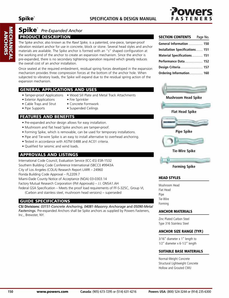
Mushroom Head Spike
Flat Head Spike
Pipe Spike
Tie-Wire Spike
Forming Spike
HEAD STYLES
Mushroom HeadFlat HeadPipeTie-WireForming
ANCHOR MATERIALS
Zinc Plated Carbon SteelType 316 Stainless Steel
ANCHOR SIZE RANGE (TYP.)
3/16” diameter x 1” length to1/2” diameter x 6-1/2” length
SUITABLE BASE MATERIALS
Normal-Weight ConcreteStructural Lightweight ConcreteHollow and Grouted CMU
Spike®
Pre-Expanded Anchor
PRODUCT DESCRIPTIONThe Spike anchor, also known as the Rawl Spike, is a patented, one-piece, tamper-proofvibration resistant anchor for use in concrete, block or stone. Several head styles and anchormaterials are available. The Spike anchor is formed with an “s” shaped configuration at the working end of the anchor to create an expansion mechanism. Since the anchor is pre-expanded, there is no secondary tightening operation required which greatly reduces the overall cost of an anchor installation.
Once seated at the required embedment, residual spring forces developed in the expansionmechanism provides three compression forces at the bottom of the anchor hole. Whensubjected to vibratory loads, the Spike will expand due to the residual spring action of theexpansion mechanism.
GENERAL APPLICATIONS AND USES• Tamper-proof Applications • Wood Sill Plate and Metal Track Attachments• Exterior Applications • Fire Sprinkler• Cable Trays and Strut • Concrete Formwork• Pipe Supports • Suspended Ceilings
FEATURES AND BENEFITS• Pre-expanded anchor design allows for easy installation.• Mushroom and flat head Spike anchors are tamper-proof.• Forming Spike, which is removable, can be used for temporary installations.• Pipe and Tie-wire Spike is an easy to install alternative to overhead anchoring.• Tested in accordance with ASTM E488 and AC01 criteria.• Qualified for seismic and wind loads.
APPROVALS AND LISTINGSInternational Code Council, Evaluation Service (ICC-ES) ESR-1532Southern Building Code Conference International (SBCCI) #9943ACity of Los Angeles (COLA) Research Report LARR – 24960Florida Building Code Approval – FL2209.7Miami-Dade County Notice of Acceptance (NOA) 03-0303.14Factory Mutual Research Corporation (FM Approvals) – J.I. ON5A1.AHFederal GSA Specification – Meets the proof load requirements of FF-S-325C, Group VI,
(Carbon and stainless steel, mushroom head versions) – superseded
GUIDE SPECIFICATIONSCSI Divisions: 03151-Concrete Anchoring, 04081-Masonry Anchorage and 05090-MetalFastenings. Pre-expanded Anchors shall be Spike anchors as supplied by Powers Fasteners,Inc., Brewster, NY.
AD
HESIV
ES
MEC
HAN
ICA
LAN
CH
OR
S
WA
LL AN
CH
OR
S
POW
DER
AC
TUA
TED
GA
S FA
STENIN
G
RO
OFIN
G
FASTEN
ERS
CA
RB
IDE
DR
ILL BITS
SPECIFICATION & DESIGN MANUAL Spike®
www.powers.com Canada: (905) 673-7295 or (514) 631-4216 Powers USA: (800) 524-3244 or (914) 235-6300 150
Spike®
Powers USA: (800) 524-3244 or (914) 235-6300 Canada: (905) 673-7295 or (514) 631-4216 www.powers.com 151
AD
HES
IVES
MEC
HAN
ICA
LAN
CH
OR
S
WA
LL
AN
CH
OR
S
POW
DER
AC
TUA
TED
GA
S FA
STEN
ING
RO
OFIN
G
FAST
ENER
S
CA
RB
IDE
DR
ILL
BIT
S
SPECIFICATION & DESIGN MANUAL
Anchor Body Grade 8.2 Carbon SteelZinc Plating ASTM B633, SC1, Type III (Fe/Zn 5)
Dimension 3/16" 1/4" 3/8" 1/2"ANSI Drill Bit Size, dbit (in.) 3/16 1/4 3/8 1/2Fixture Clearance Hole, dh (in.) 1/4 5/16 7/16 9/16Head Height (in.) 7/64 7/64 7/32 1/4Head Size, O.D. (in.) 7/16 1/2 3/4 1
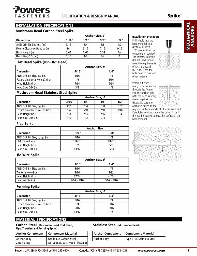
Drill a hole into the base material to a depth of at least 1/2" deeper than the embedment required.The tolerances of the drill bit used should meet the requirements of ANSI Standard B212.15. Blow the hole clean of dust and other material.
Where a fixture is used, drive the anchor through the fixture into the anchor hole until the head is firmlyseated against the fixture. Be sure the anchor is driven to therequired embedment depth. The Tie-Wire andPipe Spike versions should be driven in untilthe head is seated against the surface of thebase material.
INSTALLATION SPECIFICATIONS
Mushroom Head Carbon Steel Spike
Installation Procedure
Flat Head Spike (80°– 82° Head)
Anchor Size, d
Dimension 3/16" 1/4" 3/8" 1/2"ANSI Drill Bit Size, dbit (in.) 3/16 1/4 3/8 1/2Fixture Clearance Hole, dh (in.) 1/4 5/16 7/16 9/16Head Height (in.) 7/64 7/64 7/32 1/4Head Size, O.D. (in.) 7/16 1/2 3/4 1
Anchor Size, d
Dimension 3/16" 1/4"ANSI Drill Bit Size, dbit (in.) 3/16 1/4Fixture Clearance Hole, dh (in.) 1/4 5/16Head Height (in.) 7/64 9/64Head Size, O.D. (in.) 3/8 1/2
Anchor Size, d
Pipe Spike
Dimension 1/4" 3/8"ANSI Drill Bit Size, d, dbit (in.) 3/16 1/4UNC Thread Size 1/4-20 3/8-16Head Height (in.) 1/2 5/8Head Size, O.D. (in.) 13/32 35/64
Anchor Size
Tie-Wire Spike
Dimension 3/16" 1/4"ANSI Drill Bit Size, dbit (in.) 3/16 1/4Tie-Wire Hole (in.) 3/16 9/32Head Height (in.) 37/64 41/64Head Width (in.) 9/64 x 7/16 3/16 x 9/16
Anchor Size, d
Forming Spike
Dimension 3/16" 1/4"ANSI Drill Bit Size, dbit (in.) 3/16 1/4Fixture Clearance Hole, dh (in.) 1/4 5/16Head Height (in.) 9/16 9/16Head Size, O.D. (in.) 13/32 1/2
Anchor Size, d
Mushroom Head Stainless Steel Spike
MATERIAL SPECIFICATIONS
Carbon Steel (Mushroom Head, Flat Head, Stainless Steel (Mushroom Head)Pipe, Tie-Wire and Forming Spike)
Anchor Component Component Material
Anchor Body Type 316L Stainless Steel
Anchor Component Component Material
3/16(4.8)
1/4(6.4)
3/8(9.5)1/2
(12.7)
3/16(4.8)
1/4(6.4)
3/8(9.5)1/2
(12.7)
AD
HESIV
ES
MEC
HAN
ICA
LAN
CH
OR
S
WA
LL AN
CH
OR
S
POW
DER
AC
TUA
TED
GA
S FA
STENIN
G
RO
OFIN
G
FASTEN
ERS
CA
RB
IDE
DR
ILL BITS
SPECIFICATION & DESIGN MANUAL Spike®
www.powers.com Canada: (905) 673-7295 or (514) 631-4216 Powers USA: (800) 524-3244 or (914) 235-6300 152
520 1,080 760 1,270 860 1,310 890 1,350(2.3) (4.9) (3.4) (5.7) (3.9) (5.9) (4.0) (6.1)
540 1,230 820 1,725 980 1,860 995 1,860(2.4) (5.5) (3.7) (7.8) (4.4) (8.4) (4.5) (8.4)
780 1,800 1,000 2,000 1,260 2,155 1,520 2,310(3.5) (8.1) (4.5) (9.0) (5.7) (9.7) (6.8) (10.4)
680 1,405 820 1,630 945 1,870 1,010 2,110(3.1) (6.3) (3.7) (7.3) (4.3) (8.4) (4.5) (9.5)
720 1,585 975 1,965 1,135 2,160 1,185 2,360(3.2) (7.1) (4.4) (8.8) (5.1) (9.7) (5.3) (10.6)
830 1,815 1,200 2,020 1,410 2,220 1,620 2,585(3.7) (8.2) (5.4) (9.1) (6.3) (10.0) (7.3) (11.6)
1,785 3,645 2,120 4,480 2,630 5,025 2,875 5,075(8.0) (16.4) (9.5) (20.2) (11.8) (22.6) (12.9) (22.8)
3,215 5,345 3,620 8,460 4,015 10,320 4,410 10,860(14.5) (24.1) (16.3) (38.1) (18.1) (46.4) (19.8) (48.9)
Minimum Concrete Compressive Strength (f c )MinimumEmbedment
Depthhvin.
(mm)
AnchorDiameter
din.
(mm)
Tension Shear Tension Shear Tension Shear Tension Shearlbs. lbs. lbs. lbs. lbs. lbs. lbs. lbs.(kN) (kN) (kN) (kN) (kN) (kN) (kN) (kN)
2,000 psi (13.8 MPa) 3,000 psi (20.7 MPa) 4,000 psi (27.6 MPa) 5,000 psi (34.5 MPa)
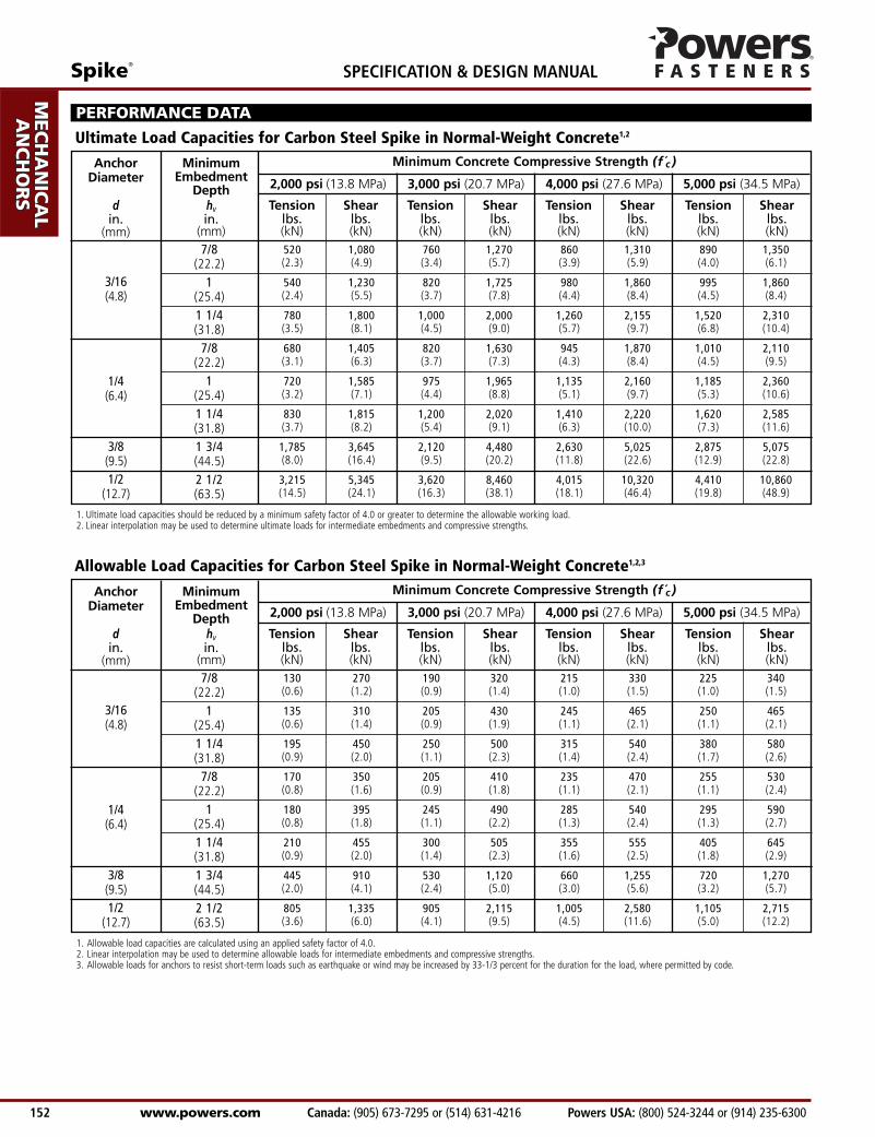
PERFORMANCE DATA
Ultimate Load Capacities for Carbon Steel Spike in Normal-Weight Concrete1,2
7/8(22.2)
1(25.4)1 1/4(31.8)
7/8(22.2)
1(25.4)1 1/4(31.8)1 3/4(44.5)2 1/2(63.5)
1. Ultimate load capacities should be reduced by a minimum safety factor of 4.0 or greater to determine the allowable working load.2. Linear interpolation may be used to determine ultimate loads for intermediate embedments and compressive strengths.
130 270 190 320 215 330 225 340(0.6) (1.2) (0.9) (1.4) (1.0) (1.5) (1.0) (1.5)
135 310 205 430 245 465 250 465(0.6) (1.4) (0.9) (1.9) (1.1) (2.1) (1.1) (2.1)
195 450 250 500 315 540 380 580(0.9) (2.0) (1.1) (2.3) (1.4) (2.4) (1.7) (2.6)
170 350 205 410 235 470 255 530(0.8) (1.6) (0.9) (1.8) (1.1) (2.1) (1.1) (2.4)
180 395 245 490 285 540 295 590(0.8) (1.8) (1.1) (2.2) (1.3) (2.4) (1.3) (2.7)
210 455 300 505 355 555 405 645(0.9) (2.0) (1.4) (2.3) (1.6) (2.5) (1.8) (2.9)
445 910 530 1,120 660 1,255 720 1,270(2.0) (4.1) (2.4) (5.0) (3.0) (5.6) (3.2) (5.7)
805 1,335 905 2,115 1,005 2,580 1,105 2,715(3.6) (6.0) (4.1) (9.5) (4.5) (11.6) (5.0) (12.2)
Minimum Concrete Compressive Strength (f c )MinimumEmbedment
Depthhvin.
(mm)
AnchorDiameter
din.
(mm)
Tension Shear Tension Shear Tension Shear Tension Shearlbs. lbs. lbs. lbs. lbs. lbs. lbs. lbs.(kN) (kN) (kN) (kN) (kN) (kN) (kN) (kN)
2,000 psi (13.8 MPa) 3,000 psi (20.7 MPa) 4,000 psi (27.6 MPa) 5,000 psi (34.5 MPa)
7/8(22.2)
1(25.4)1 1/4(31.8)
7/8(22.2)
1(25.4)1 1/4(31.8)1 3/4(44.5)2 1/2(63.5)
1. Allowable load capacities are calculated using an applied safety factor of 4.0.2. Linear interpolation may be used to determine allowable loads for intermediate embedments and compressive strengths.3. Allowable loads for anchors to resist short-term loads such as earthquake or wind may be increased by 33-1/3 percent for the duration for the load, where permitted by code.
Allowable Load Capacities for Carbon Steel Spike in Normal-Weight Concrete1,2,3
Spike®
Powers USA: (800) 524-3244 or (914) 235-6300 Canada: (905) 673-7295 or (514) 631-4216 www.powers.com 153
AD
HES
IVES
MEC
HAN
ICA
LAN
CH
OR
S
WA
LL
AN
CH
OR
S
POW
DER
AC
TUA
TED
GA
S FA
STEN
ING
RO
OFIN
G
FAST
ENER
S
CA
RB
IDE
DR
ILL
BIT
S
SPECIFICATION & DESIGN MANUAL
3/16(4.8)
1/4(6.4)
3/8(9.5)
490 920 715 1,155 850 1,220 875 1,290(2.2) (4.1) (3.2) (5.2) (3.8) (5.5) (3.9) (5.8)
500 1,175 810 1,650 975 1,740 985 1,830(2.3) (5.3) (3.6) (7.4) (4.4) (7.8) (4.4) (8.2)
740 1,735 970 1,930 1,160 2,040 1,420 2,150(3.3) (7.8) (4.4) (8.7) (5.2) (9.2) (6.4) (9.7)
635 1,350 790 1,570 880 1,785 980 2,000(2.9) (6.1) (3.6) (7.1) (4.0) (8.0) (4.4) (9.0)
670 1,565 970 1,845 1,045 2,095 1,120 2,250(3.0) (7.0) (4.4) (8.3) (4.7) (9.4) (5.0) (10.1)
795 1,765 1,080 1,965 1,375 2,145 1,580 2,325(3.6) (7.9) (4.9) (8.8) (6.2) (9.7) (7.1) (10.5)
1,575 3,155 1,990 3,880 2,420 4,150 2,570 4,425(7.1) (14.2) (9.0) (17.5) (10.9) (18.7) (11.6) (19.9)
Minimum Concrete Compressive Strength (f c )MinimumEmbedment
Depthhvin.
(mm)
AnchorDiameter
din.
(mm)
Tension Shear Tension Shear Tension Shear Tension Shearlbs. lbs. lbs. lbs. lbs. lbs. lbs. lbs.(kN) (kN) (kN) (kN) (kN) (kN) (kN) (kN)
2,000 psi (13.8 MPa) 3,000 psi (20.7 MPa) 4,000 psi (27.6 MPa) 5,000 psi (34.5 MPa)
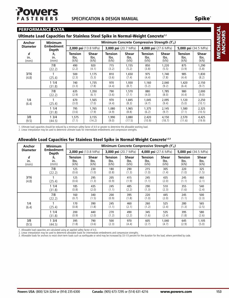
PERFORMANCE DATA
Ultimate Load Capacities for Stainless Steel Spike in Normal-Weight Concrete1,2
7/8(22.2)
1(25.4)1 1/4(31.8)
7/8(22.2)
1(25.4)1 1/4(31.8)1 3/4(44.5)
1. Ultimate load capacities should be reduced by a minimum safety factor of 4.0 or greater to determine the allowable working load.2. Linear interpolation may be used to determine ultimate loads for intermediate embedments and compressive strengths.
3/16(4.8)
1/4(6.4)
3/8(9.5)
125 230 180 290 215 305 220 325(0.6) (1.0) (0.8) (1.3) (1.0) (1.4) (1.0) (1.5)
125 295 205 415 245 435 245 460(0.6) (1.3) (0.9) (1.9) (1.1) (2.0) (1.1) (2.1)
185 435 245 485 290 510 355 540(0.8) (2.0) (1.1) (2.2) (1.3) (2.3) (1.6) (2.4)
160 340 200 395 220 445 245 500(0.7) (1.5) (0.9) (1.8) (1.0) (2.0) (1.1) (2.3)
170 390 245 460 260 525 280 565(0.8) (1.8) (1.1) (2.1) (1.2) (2.4) (1.3) (2.5)
200 440 270 490 345 535 395 580(0.9) (2.0) (1.2) (2.2) (1.6) (2.4) (1.8) (2.6)
395 790 500 970 605 1,040 645 1,105(1.8) (3.6) (2.3) (4.4) (2.7) (4.7) (2.9) (5.0)
Minimum Concrete Compressive Strength (f c )MinimumEmbedment
Depthhvin.
(mm)
AnchorDiameter
din.
(mm)
Tension Shear Tension Shear Tension Shear Tension Shearlbs. lbs. lbs. lbs. lbs. lbs. lbs. lbs.(kN) (kN) (kN) (kN) (kN) (kN) (kN) (kN)
2,000 psi (13.8 MPa) 3,000 psi (20.7 MPa) 4,000 psi (27.6 MPa) 5,000 psi (34.5 MPa)
Allowable Load Capacities for Stainless Steel Spike in Normal-Weight Concrete1,2,3
7/8(22.2)
1(25.4)1 1/4(31.8)
7/8(22.2)
1(25.4)1 1/4(31.8)1 3/4(44.5)
1. Allowable load capacities are calculated using an applied safety factor of 4.0.2. Linear interpolation may be used to determine allowable loads for intermediate embedments and compressive strengths.3. Allowable loads for anchors to resist short-term loads such as earthquake or wind may be increased by 33-1/3 percent for the duration for the load, where permitted by code.
1. Ultimate load capacities should be reduced by a minimum safety factor of 4.0 or greater to determine the allowable working load.2. Linear interpolation may be used to determine ultimate loads for intermediate compressive strengths.
AD
HESIV
ES
MEC
HAN
ICA
LAN
CH
OR
S
WA
LL AN
CH
OR
S
POW
DER
AC
TUA
TED
GA
S FA
STENIN
G
RO
OFIN
G
FASTEN
ERS
CA
RB
IDE
DR
ILL BITS
SPECIFICATION & DESIGN MANUAL Spike®
www.powers.com Canada: (905) 673-7295 or (514) 631-4216 Powers USA: (800) 524-3244 or (914) 235-6300 154
1/4(6.4)3/8(9.5)
780 975 1,260 975 1,260 975 1,260 975(3.5) (4.4) (5.7) (4.4) (5.7) (4.4) (5.7) (4.4)
1,100 1,815 1,660 2,020 2,000 2,100 2,320 2,180(5.0) (8.2) (7.5) (9.1) (9.0) (9.5) (10.4) (9.8)
Minimum Concrete Compressive Strength (f c )MinimumEmbed.Depth
hvin.
(mm)
AnchorDia.
din.
(mm)
3/16
1/4
DrillBitDia.dbitin.
3/16
1/4
DrillBitDia.dbitin.
Tension Shear Tension Shear Tension Shear Tension Shearlbs. lbs. lbs. lbs. lbs. lbs. lbs. lbs.(kN) (kN) (kN) (kN) (kN) (kN) (kN) (kN)
2,000 psi (13.8 MPa) 3,000 psi (20.7 MPa) 4,000 psi (27.6 MPa) 5,000 psi (34.5 MPa)
PERFORMANCE DATA
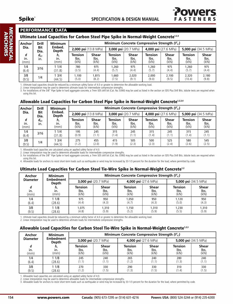
Ultimate Load Capacities for Carbon Steel Pipe Spike in Normal-Weight Concrete1,2,3
1 1/4(31.8)1 3/4(44.5)
1. Ultimate load capacities should be reduced by a minimum safety factor of 4.0 or greater to determine the allowable working load.2. Linear interpolation may be used to determine ultimate loads for intermediate compressive strengths.3. For installations of the 3/8" Pipe Spike in hard aggregate concrete, a 7mm SDS drill bit (Cat. No. 0390) may be used as listed in the section on SDS Plus Drill Bits. Jobsite tests are required when
using this bit.
1/4(6.4)3/8(9.5)
195 245 315 245 315 245 315 245(0.9) (1.1) (1.4) (1.1) (1.4) (1.1) (1.4) (1.1)
275 455 415 505 500 525 580 545(1.2) (2.0) (1.9) (2.3) (2.3) (2.4) (2.6) (2.5)
Minimum Concrete Compressive Strength (f c )MinimumEmbed.Depth
hvin.
(mm)
AnchorDia.
din.
(mm)
Tension Shear Tension Shear Tension Shear Tension Shearlbs. lbs. lbs. lbs. lbs. lbs. lbs. lbs.(kN) (kN) (kN) (kN) (kN) (kN) (kN) (kN)
2,000 psi (13.8 MPa) 3,000 psi (20.7 MPa) 4,000 psi (27.6 MPa) 5,000 psi (34.5 MPa)
Allowable Load Capacities for Carbon Steel Pipe Spike in Normal-Weight Concrete1,2,3,4
1 1/4(31.8)1 3/4(44.5)
1. Allowable load capacities are calculated using an applied safety factor of 4.0.2. Linear interpolation may be used to determine allowable loads for intermediate compressive strengths.3. For installations of the 3/8" Pipe Spike in hard aggregate concrete, a 7mm SDS drill bit (Cat. No. 0390) may be used as listed in the section on SDS Plus Drill Bits. Jobsite tests are required when
using this bit.4. Allowable loads for anchors to resist short-term loads such as earthquake or wind may be increased by 33-1/3 percent for the duration for the load, where permitted by code.
1/4(6.4)3/8(9.5)
975 950 1,050 950 1,120 950(4.4) (4.3) (4.7) (4.3) (5.0) (4.3)
1,075 1,310 1,150 1,310 1,230 1,310(4.8) (5.9) (5.2) (5.9) (5.5) (5.9)
Minimum Concrete Compressive Strength (f c )MinimumEmbedment
Depthhvin.
(mm)
AnchorDiameter
din.
(mm)
Tension Shear Tension Shear Tension Shearlbs. lbs. lbs. lbs. lbs. lbs.(kN) (kN) (kN) (kN) (kN) (kN)
3,000 psi (20.7 MPa) 4,000 psi (27.6 MPa) 5,000 psi (34.5 MPa)
Ultimate Load Capacities for Carbon Steel Tie-Wire Spike in Normal-Weight Concrete1,2
1 1/8(28.6)1 1/8(28.6)
1. Allowable load capacities are calculated using an applied safety factor of 4.0.2. Linear interpolation may be used to determine allowable loads for intermediate compressive strengths.3. Allowable loads for anchors to resist short-term loads such as earthquake or wind may be increased by 33-1/3 percent for the duration for the load, where permitted by code.
1/4(6.4)3/8(9.5)
245 240 265 240 280 240(1.1) (1.1) (1.2) (1.1) (1.3) (1.1)
270 330 290 330 310 330(1.2) (1.5) (1.3) (1.5) (1.4) (1.5)
Minimum Concrete Compressive Strength (f c )MinimumEmbedment
Depthhvin.
(mm)
AnchorDiameter
din.
(mm)
Tension Shear Tension Shear Tension Shearlbs. lbs. lbs. lbs. lbs. lbs.(kN) (kN) (kN) (kN) (kN) (kN)
3,000 psi (20.7 MPa) 4,000 psi (27.6 MPa) 5,000 psi (34.5 MPa)
Allowable Load Capacities for Carbon Steel Tie-Wire Spike in Normal-Weight Concrete1,2,3
1 1/8(28.6)1 1/8(28.6)
Spike®
Powers USA: (800) 524-3244 or (914) 235-6300 Canada: (905) 673-7295 or (514) 631-4216 www.powers.com 155
AD
HES
IVES
MEC
HAN
ICA
LAN
CH
OR
S
WA
LL
AN
CH
OR
S
POW
DER
AC
TUA
TED
GA
S FA
STEN
ING
RO
OFIN
G
FAST
ENER
S
CA
RB
IDE
DR
ILL
BIT
S
SPECIFICATION & DESIGN MANUAL
1 1/4(31.8)1 1/4(31.8)1 3/4(44.5)2 1/2(63.5)
3/16(4.8)1/4(6.4)
780 1,800 1,000 2,000 1,260 2,155 1,520 2,310(3.5) (8.1) (4.5) (9.0) (5.7) (9.7) (6.8) (10.4)830 1,815 1,200 2,020 1,410 2,220 1,620 2,585(3.7) (8.2) (5.4) (9.1) (6.3) (10.0) (7.3) (11.6)
Minimum Concrete Compressive Strength (f c )MinimumEmbed.Depth
hvin.
(mm)
AnchorDiameter
din.
(mm)
Tension Shear Tension Shear Tension Shear Tension Shearlbs. lbs. lbs. lbs. lbs. lbs. lbs. lbs.(kN) (kN) (kN) (kN) (kN) (kN) (kN) (kN)
2,000 psi (13.8 MPa) 3,000 psi (20.7 MPa) 4,000 psi (27.6 MPa) 5,000 psi (34.5 MPa)
PERFORMANCE DATA
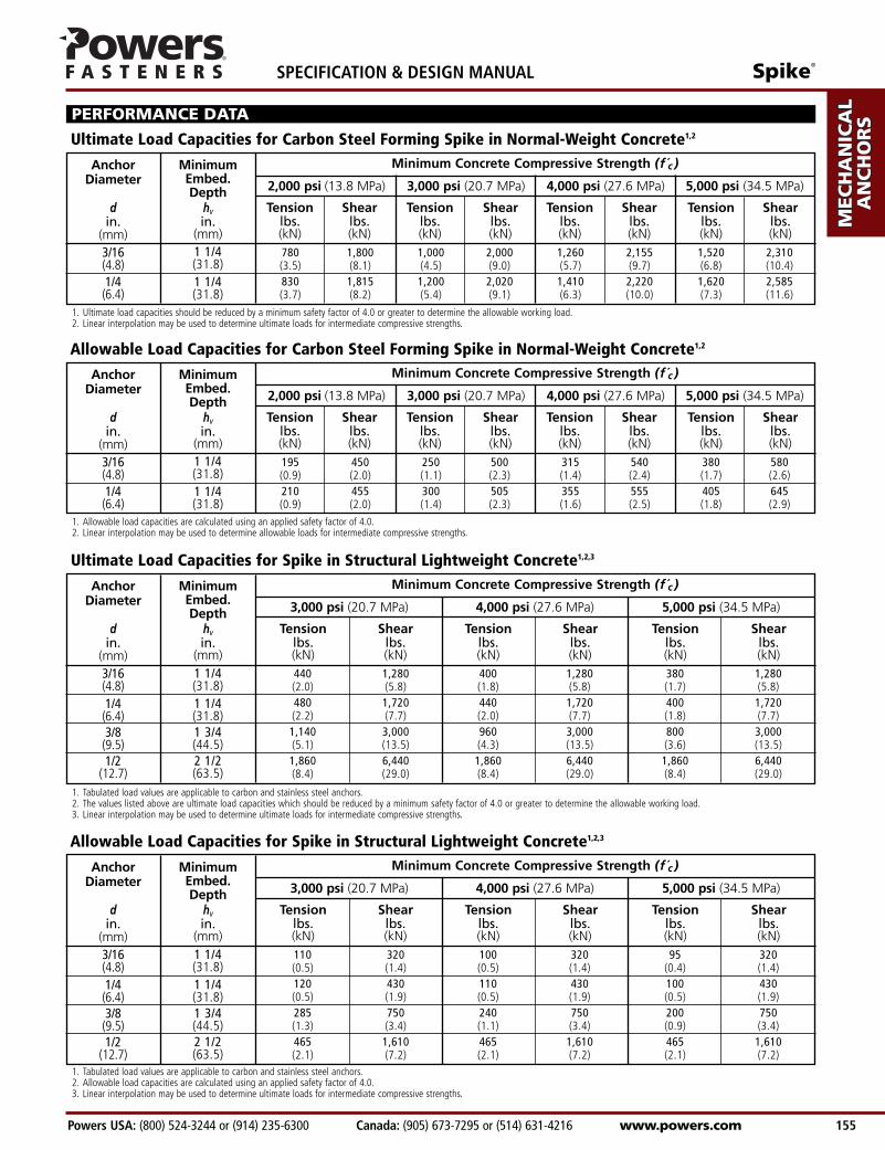
Ultimate Load Capacities for Carbon Steel Forming Spike in Normal-Weight Concrete1,2
1 1/4(31.8)1 1/4(31.8)
1. Ultimate load capacities should be reduced by a minimum safety factor of 4.0 or greater to determine the allowable working load.2. Linear interpolation may be used to determine ultimate loads for intermediate compressive strengths.
1. Tabulated load values are applicable to carbon and stainless steel anchors.2. The values listed above are ultimate load capacities which should be reduced by a minimum safety factor of 4.0 or greater to determine the allowable working load.3. Linear interpolation may be used to determine ultimate loads for intermediate compressive strengths.
3/16(4.8)1/4(6.4)3/8(9.5)1/2
(12.7)
440 1,280 400 1,280 380 1,280(2.0) (5.8) (1.8) (5.8) (1.7) (5.8)480 1,720 440 1,720 400 1,720(2.2) (7.7) (2.0) (7.7) (1.8) (7.7)1,140 3,000 960 3,000 800 3,000(5.1) (13.5) (4.3) (13.5) (3.6) (13.5)1,860 6,440 1,860 6,440 1,860 6,440(8.4) (29.0) (8.4) (29.0) (8.4) (29.0)
Minimum Concrete Compressive Strength (f c )MinimumEmbed.Depth
hvin.
(mm)
AnchorDiameter
din.
(mm)
Tension Shear Tension Shear Tension Shearlbs. lbs. lbs. lbs. lbs. lbs.(kN) (kN) (kN) (kN) (kN) (kN)
3,000 psi (20.7 MPa) 4,000 psi (27.6 MPa) 5,000 psi (34.5 MPa)
Ultimate Load Capacities for Spike in Structural Lightweight Concrete1,2,3
1 1/4(31.8)1 1/4(31.8)1 3/4(44.5)2 1/2(63.5)
1. Tabulated load values are applicable to carbon and stainless steel anchors.2. Allowable load capacities are calculated using an applied safety factor of 4.0.3. Linear interpolation may be used to determine ultimate loads for intermediate compressive strengths.
3/16(4.8)1/4(6.4)3/8(9.5)1/2
(12.7)
110 320 100 320 95 320(0.5) (1.4) (0.5) (1.4) (0.4) (1.4)120 430 110 430 100 430(0.5) (1.9) (0.5) (1.9) (0.5) (1.9)285 750 240 750 200 750(1.3) (3.4) (1.1) (3.4) (0.9) (3.4)465 1,610 465 1,610 465 1,610(2.1) (7.2) (2.1) (7.2) (2.1) (7.2)
Minimum Concrete Compressive Strength (f c )MinimumEmbed.Depth
hvin.
(mm)
AnchorDiameter
din.
(mm)
Tension Shear Tension Shear Tension Shearlbs. lbs. lbs. lbs. lbs. lbs.(kN) (kN) (kN) (kN) (kN) (kN)
3,000 psi (20.7 MPa) 4,000 psi (27.6 MPa) 5,000 psi (34.5 MPa)
Allowable Load Capacities for Spike in Structural Lightweight Concrete1,2,3
3/16(4.8)1/4(6.4)
195 450 250 500 315 540 380 580(0.9) (2.0) (1.1) (2.3) (1.4) (2.4) (1.7) (2.6)210 455 300 505 355 555 405 645(0.9) (2.0) (1.4) (2.3) (1.6) (2.5) (1.8) (2.9)
Minimum Concrete Compressive Strength (f c )MinimumEmbed.Depth
hvin.
(mm)
AnchorDiameter
din.
(mm)
Tension Shear Tension Shear Tension Shear Tension Shearlbs. lbs. lbs. lbs. lbs. lbs. lbs. lbs.(kN) (kN) (kN) (kN) (kN) (kN) (kN) (kN)
2,000 psi (13.8 MPa) 3,000 psi (20.7 MPa) 4,000 psi (27.6 MPa) 5,000 psi (34.5 MPa)
Allowable Load Capacities for Carbon Steel Forming Spike in Normal-Weight Concrete1,2
1 1/4(31.8)1 1/4(31.8)
1. Allowable load capacities are calculated using an applied safety factor of 4.0.2. Linear interpolation may be used to determine allowable loads for intermediate compressive strengths.
7/8(22.2)
1(25.4)
1 1/4(31.8)
7/8(22.2)
1(25.4)
1 1/4(31.8)
AD
HESIV
ES
MEC
HAN
ICA
LAN
CH
OR
S
WA
LL AN
CH
OR
S
POW
DER
AC
TUA
TED
GA
S FA
STENIN
G
RO
OFIN
G
FASTEN
ERS
CA
RB
IDE
DR
ILL BITS
SPECIFICATION & DESIGN MANUAL Spike®
www.powers.com Canada: (905) 673-7295 or (514) 631-4216 Powers USA: (800) 524-3244 or (914) 235-6300 156
3/16(4.8)1/4(6.4)3/8(9.5)1/2
(12.7)
1 1/4 560 2,000 140 500(31.8) (2.5) (9.0) (0.6) (2.3)
1 1/4 560 2,000 140 500(31.8) (2.5) (9.0) (0.6) (2.3)
1 3/4 600 2,620 150 655(44.5) (2.7) (11.8) (0.7) (2.9)
2 1/2 1,120 3,020 280 755(63.5) (5.0) (13.6) (1.3) (3.4)
MinimumEmbedment
Depthhvin.
(mm)
AnchorDiameter
din.
(mm)
Tension Shear Tension Shearlbs. lbs. lbs. lbs.(kN) (kN) (kN) (kN)
Ultimate Load
Minimum 1 1/2" Wide Deck
Allowable Load
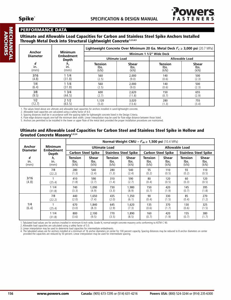
1. The values listed above are ultimate and allowable load capacities for anchors installed in sand-lightweight concrete.2. Allowable load capacities are calculated using a safety factor of 4.0.3. Spacing distances shall be in accordance with the spacing table for lightweight concrete listed in the Design Criteria.4. Flute edge distance equals one-half the minimum deck width. Linear interpolation may be used for flute edge distance between those listed.5. Anchors are permitted to be installed in the lower or upper flute of the metal deck provided the proper installation procedures are maintained.
Lightweight Concrete Over Minimum 20 Ga. Metal Deck f c ≥ 3,000 psi (20.7 MPa)
PERFORMANCE DATA
Ultimate and Allowable Load Capacities for Carbon and Stainless Steel Spike Anchors Installed Through Metal Deck into Structural Lightweight Concrete1,2,3,4,5
3/16(4.8)
1/4(6.4)
1. Tabulated load values are for anchors installed in minimum 6-inch wide, Grade N, normal-weight concrete masonry units conforming to ASTM C 90.2. Allowable load capacities are calculated using a safety factor of 5.0.3. Linear interpolation may be used to determine load capacities for intermediate embedments.4. The tabulated values are for anchors installed at a minimum of 16 anchor diameters on center for 100 percent capacity. Spacing distances may be reduced to 8 anchor diameters on center
provided the capacities are reduced by 50 percent. Linear interpolation may be used for intermediate spacing.
280 540 280 540 55 110 55 110(1.3) (2.4) (1.3) (2.4) (0.2) (0.5) (0.2) (0.5)
410 590 310 590 80 120 60 120(1.8) (2.7) (1.4) (2.7) (0.4) (0.5) (0.3) (0.5)
740 1,090 730 1,980 150 420 145 395(3.3) (4.9) (3.3) (8.9) (0.7) (1.9) (0.7) (1.8)
440 1,650 435 1,350 90 330 85 270(2.0) (7.4) (2.0) (6.1) (0.4) (1.5) (0.4) (1.2)
670 1,840 645 1,620 135 370 130 325(3.0) (8.3) (2.9) (7.3) (0.6) (1.7) (0.6) (1.5)
800 2,100 770 1,890 160 420 155 380(3.6) (9.5) (3.5) (8.5) (0.7) (1.9) (0.7) (1.7)
Allowable Load
Normal-Weight CMU – f m ≥ 1,500 psi (10.4 MPa)
MinimumEmbedment
Depthhvin.
(mm)
AnchorDiameter
din.
(mm)
Tension Shear Tension Shear Tension Shear Tension Shearlbs. lbs. lbs. lbs. lbs. lbs. lbs. lbs.(kN) (kN) (kN) (kN) (kN) (kN) (kN) (kN)
Carbon Steel Spike Stainless Steel Spike Carbon Steel Spike Stainless Steel Spike
Ultimate Load
Ultimate and Allowable Load Capacities for Carbon Steel and Stainless Steel Spike in Hollow andGrouted Concrete Masonry1,2,3,4
Spike®
Powers USA: (800) 524-3244 or (914) 235-6300 Canada: (905) 673-7295 or (514) 631-4216 www.powers.com 157
AD
HES
IVES
MEC
HAN
ICA
LAN
CH
OR
S
WA
LL
AN
CH
OR
S
POW
DER
AC
TUA
TED
GA
S FA
STEN
ING
RO
OFIN
G
FAST
ENER
S
CA
RB
IDE
DR
ILL
BIT
S
SPECIFICATION & DESIGN MANUAL
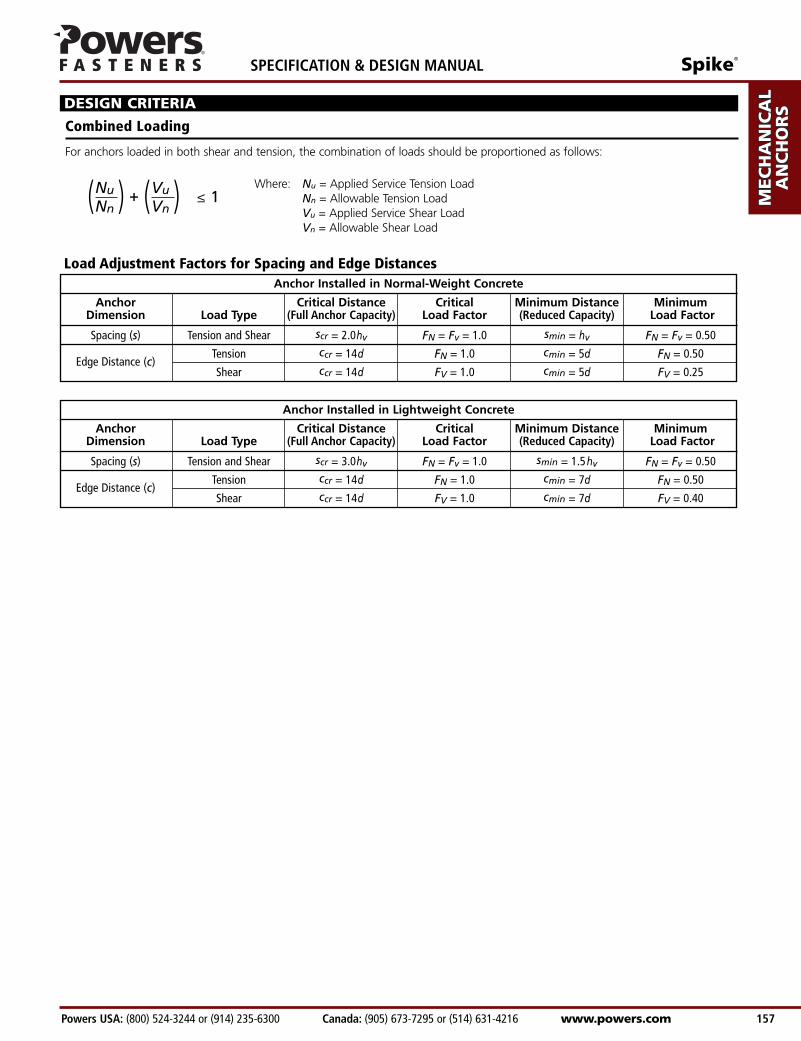
DESIGN CRITERIA
NuNn( ) Vu
Vn( )+ ≤ 1
Combined Loading
For anchors loaded in both shear and tension, the combination of loads should be proportioned as follows:
Where: Nu = Applied Service Tension LoadNn = Allowable Tension LoadVu = Applied Service Shear LoadVn = Allowable Shear Load
Load Adjustment Factors for Spacing and Edge DistancesAnchor Installed in Normal-Weight Concrete
Anchor Critical Distance Critical Minimum Distance MinimumDimension Load Type (Full Anchor Capacity) Load Factor (Reduced Capacity) Load Factor
Spacing (s) Tension and Shear scr = 2.0hv FN = Fv = 1.0 smin = hv FN = Fv = 0.50
Edge Distance (c)Tension ccr = 14d FN = 1.0 cmin = 5d FN = 0.50
Shear ccr = 14d FV = 1.0 cmin = 5d FV = 0.25
Anchor Installed in Lightweight Concrete
Anchor Critical Distance Critical Minimum Distance MinimumDimension Load Type (Full Anchor Capacity) Load Factor (Reduced Capacity) Load Factor
Spacing (s) Tension and Shear scr = 3.0hv FN = Fv = 1.0 smin = 1.5hv FN = Fv = 0.50
Edge Distance (c)Tension ccr = 14d FN = 1.0 cmin = 7d FN = 0.50
Shear ccr = 14d FV = 1.0 cmin = 7d FV = 0.40
AD
HESIV
ES
MEC
HAN
ICA
LAN
CH
OR
S
WA
LL AN
CH
OR
S
POW
DER
AC
TUA
TED
GA
S FA
STENIN
G
RO
OFIN
G
FASTEN
ERS
CA
RB
IDE
DR
ILL BITS
SPECIFICATION & DESIGN MANUAL Spike®
www.powers.com Canada: (905) 673-7295 or (514) 631-4216 Powers USA: (800) 524-3244 or (914) 235-6300 158
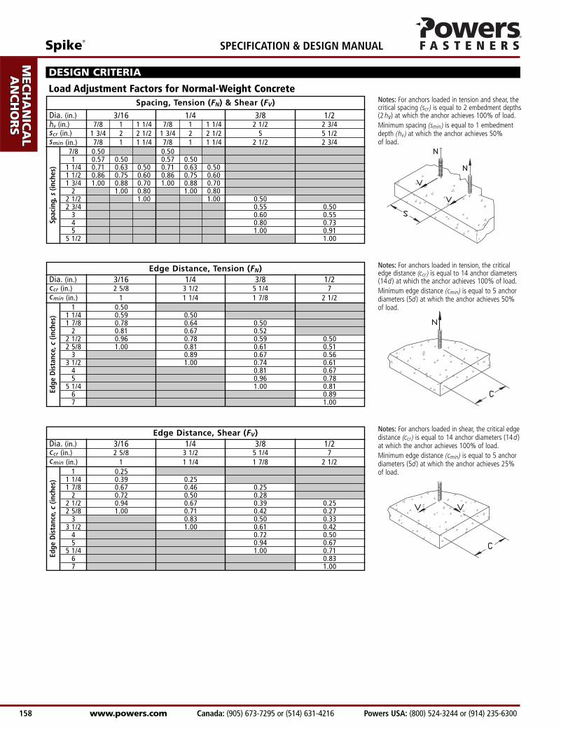
Edge Distance, Tension (FN)Dia. (in.) 3/16 1/4 3/8 1/2ccr (in.) 2 5/8 3 1/2 5 1/4 7 cmin (in.) 1 1 1/4 1 7/8 2 1/2
Notes: For anchors loaded in shear, the critical edgedistance (ccr ) is equal to 14 anchor diameters (14d )at which the anchor achieves 100% of load.Minimum edge distance (cmin) is equal to 5 anchordiameters (5d ) at which the anchor achieves 25%of load.
Notes: For anchors loaded in tension, the criticaledge distance (ccr ) is equal to 14 anchor diameters(14d ) at which the anchor achieves 100% of load.Minimum edge distance (cmin) is equal to 5 anchordiameters (5d ) at which the anchor achieves 50% of load.
Edge
Dis
tanc
e,c
(inch
es)
Notes: For anchors loaded in tension and shear, thecritical spacing (scr ) is equal to 2 embedment depths(2 hv) at which the anchor achieves 100% of load.Minimum spacing (smin ) is equal to 1 embedmentdepth (hv ) at which the anchor achieves 50% of load.
1 0.501 1/4 0.59 0.501 7/8 0.78 0.64 0.50
2 0.81 0.67 0.522 1/2 0.96 0.78 0.59 0.502 5/8 1.00 0.81 0.61 0.51
3 0.89 0.67 0.563 1/2 1.00 0.74 0.61
4 0.81 0.675 0.96 0.78
5 1/4 1.00 0.816 0.897 1.00
Edge Distance, Shear (FV)Dia. (in.) 3/16 1/4 3/8 1/2ccr (in.) 2 5/8 3 1/2 5 1/4 7 cmin (in.) 1 1 1/4 1 7/8 2 1/2
Edge
Dis
tanc
e,c
(inch
es)
1 0.251 1/4 0.39 0.251 7/8 0.67 0.46 0.25
2 0.72 0.50 0.282 1/2 0.94 0.67 0.39 0.252 5/8 1.00 0.71 0.42 0.27
3 0.83 0.50 0.333 1/2 1.00 0.61 0.42
4 0.72 0.505 0.94 0.67
5 1/4 1.00 0.716 0.837 1.00
7/8 0.50 0.501 0.57 0.50 0.57 0.50
1 1/4 0.71 0.63 0.50 0.71 0.63 0.501 1/2 0.86 0.75 0.60 0.86 0.75 0.601 3/4 1.00 0.88 0.70 1.00 0.88 0.70
2 1.00 0.80 1.00 0.802 1/2 1.00 1.00 0.502 3/4 0.55 0.50
3 0.60 0.554 0.80 0.735 1.00 0.91
5 1/2 1.00
Load Adjustment Factors for Normal-Weight Concrete
DESIGN CRITERIA
Spacing, Tension (FN) & Shear (FV)
Dia. (in.) 3/16 1/4 3/8 1/2hv (in.) 7/8 1 1 1/4 7/8 1 1 1/4 2 1/2 2 3/4scr (in.) 1 3/4 2 2 1/2 1 3/4 2 2 1/2 5 5 1/2smin (in.) 7/8 1 1 1/4 7/8 1 1 1/4 2 1/2 2 3/4
Spac
ing,
s(in
ches
)
Spike®
Powers USA: (800) 524-3244 or (914) 235-6300 Canada: (905) 673-7295 or (514) 631-4216 www.powers.com 159
AD
HES
IVES
MEC
HAN
ICA
LAN
CH
OR
S
WA
LL
AN
CH
OR
S
POW
DER
AC
TUA
TED
GA
S FA
STEN
ING
RO
OFIN
G
FAST
ENER
S
CA
RB
IDE
DR
ILL
BIT
S
SPECIFICATION & DESIGN MANUAL
1 3/8 0.50 0.501 1/2 0.57 0.50 0.57 0.501 7/8 0.71 0.63 0.50 0.71 0.63 0.501 1/2 0.57 0.50 0.40 0.57 0.50 0.402 5/8 1.00 0.88 0.70 1.00 0.88 0.70
3 1.00 0.80 1.00 0.803 3/4 1.00 1.00 0.50
4 0.534 1/8 0.55 0.50
5 0.67 0.616 0.80 0.737 0.93 0.85
7 1/2 1.00 0.918 1/4 1.00
Spac
ing,
s(in
ches
)
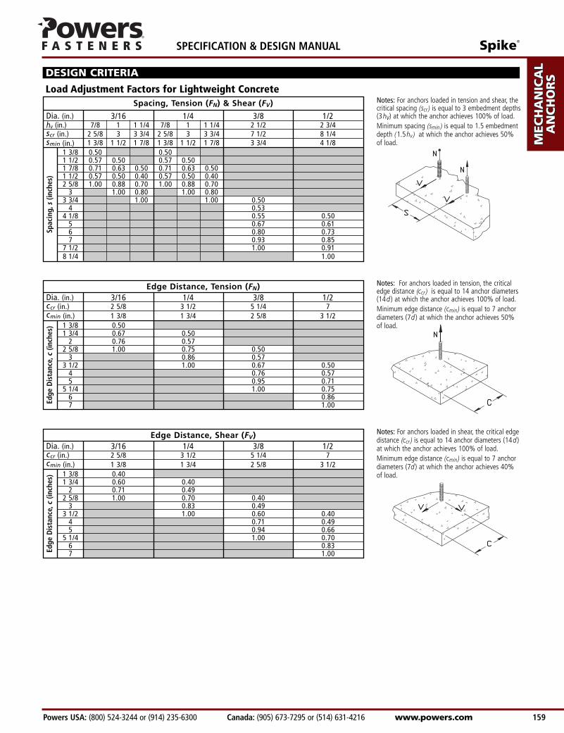
Load Adjustment Factors for Lightweight Concrete
Notes: For anchors loaded in shear, the critical edgedistance (ccr ) is equal to 14 anchor diameters (14d )at which the anchor achieves 100% of load.Minimum edge distance (cmin) is equal to 7 anchordiameters (7d ) at which the anchor achieves 40%of load.
DESIGN CRITERIA
Notes: For anchors loaded in tension and shear, thecritical spacing (scr ) is equal to 3 embedment depths(3hv) at which the anchor achieves 100% of load.Minimum spacing (smin ) is equal to 1.5 embedmentdepth (1.5hv) at which the anchor achieves 50% of load.
Spacing, Tension (FN) & Shear (FV)
Dia. (in.) 3/16 1/4 3/8 1/2hv (in.) 7/8 1 1 1/4 7/8 1 1 1/4 2 1/2 2 3/4scr (in.) 2 5/8 3 3 3/4 2 5/8 3 3 3/4 7 1/2 8 1/4smin (in.) 1 3/8 1 1/2 1 7/8 1 3/8 1 1/2 1 7/8 3 3/4 4 1/8
Edge Distance, Shear (FV)
1 3/8 0.401 3/4 0.60 0.40
2 0.71 0.492 5/8 1.00 0.70 0.40
3 0.83 0.493 1/2 1.00 0.60 0.40
4 0.71 0.495 0.94 0.66
5 1/4 1.00 0.706 0.837 1.00
Dia. (in.) 3/16 1/4 3/8 1/2ccr (in.) 2 5/8 3 1/2 5 1/4 7 cmin (in.) 1 3/8 1 3/4 2 5/8 3 1/2
Edge
Dis
tanc
e,c
(inch
es)
Notes: For anchors loaded in tension, the criticaledge distance (ccr ) is equal to 14 anchor diameters(14d ) at which the anchor achieves 100% of load.Minimum edge distance (cmin) is equal to 7 anchordiameters (7d ) at which the anchor achieves 50% of load.1 3/8 0.50
1 3/4 0.67 0.502 0.76 0.57
2 5/8 1.00 0.75 0.503 0.86 0.57
3 1/2 1.00 0.67 0.504 0.76 0.575 0.95 0.71
5 1/4 1.00 0.756 0.867 1.00Ed
ge D
ista
nce,
c (in
ches
)
Edge Distance, Tension (FN)Dia. (in.) 3/16 1/4 3/8 1/2ccr (in.) 2 5/8 3 1/2 5 1/4 7 cmin (in.) 1 3/8 1 3/4 2 5/8 3 1/2
AD
HESIV
ES
MEC
HAN
ICA
LAN
CH
OR
S
WA
LL AN
CH
OR
S
POW
DER
AC
TUA
TED
GA
S FA
STENIN
G
RO
OFIN
G
FASTEN
ERS
CA
RB
IDE
DR
ILL BITS
SPECIFICATION & DESIGN MANUAL Spike®
www.powers.com Canada: (905) 673-7295 or (514) 631-4216 Powers USA: (800) 524-3244 or (914) 235-6300 160
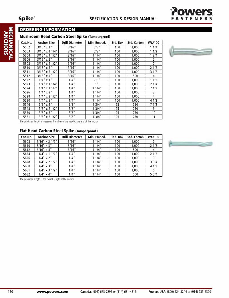
Cat. No. Anchor Size Drill Diameter Min. Embed. Std. Box Std. Carton Wt./1005502 3/16" x 1" 3/16" 7/8" 100 1,000 1 1/45503 3/16" x 1 1/4" 3/16" 7/8" 100 1,000 1 1/25504 3/16" x 1 1/2" 3/16" 1 1/4" 100 1,000 1 3/45506 3/16" x 2" 3/16" 1 1/4" 100 1,000 25508 3/16" x 2 1/2" 3/16" 1 1/4" 100 1,000 25510 3/16" x 3" 3/16" 1 1/4" 100 1,000 2 1/25511 3/16" x 3 1/2" 3/16" 1 1/4" 100 1,000 3 1/25512 3/16" x 4" 3/16" 1 1/4" 100 500 45522 1/4" x 1" 1/4" 7/8" 100 1,000 1 1/25523 1/4" x 1 1/4" 1/4" 1" 100 1,000 2 1/45524 1/4" x 1 1/2" 1/4" 1 1/4" 100 1,000 2 1/25526 1/4" x 2" 1/4" 1 1/4" 100 1,000 35528 1/4" x 2 1/2" 1/4" 1 1/4" 100 1,000 45530 1/4" x 3" 1/4" 1 1/4" 100 1,000 4 1/25546 3/8" x 2" 3/8" 1 3/4" 25 250 7 1/25548 3/8" x 2 1/2" 3/8" 1 3/4" 25 250 95550 3/8" x 3" 3/8" 1 3/4" 25 250 105551 3/8" x 3 1/2" 3/8" 1 3/4" 25 250 11
ORDERING INFORMATION
Mushroom Head Carbon Steel Spike (Tamperproof)
Cat. No. Anchor Size Drill Diameter Min. Embed. Std. Box Std. Carton Wt./1005608 3/16" x 2 1/2" 3/16" 1 1/4" 100 1,000 25610 3/16" x 3" 3/16" 1 1/4" 100 1,000 2 1/25612 3/16" x 4" 3/16" 1 1/4" 100 500 45624 1/4" x 1 1/2" 1/4" 1 1/4" 100 1,000 2 1/25626 1/4" x 2" 1/4" 1 1/4" 100 1,000 35628 1/4" x 2 1/2" 1/4" 1 1/4" 100 1,000 3 3/45630 1/4" x 3" 1/4" 1 1/4" 100 1,000 4 1/25631 1/4" x 3 1/2" 1/4" 1 1/4" 100 1,000 55632 1/4" x 4" 1/4" 1 1/4" 100 500 5 3/4
Flat Head Carbon Steel Spike (Tamperproof)
The published length is measured from below the head to the end of the anchor.
The published length is the overall length of the anchor.
Spike®
Powers USA: (800) 524-3244 or (914) 235-6300 Canada: (905) 673-7295 or (514) 631-4216 www.powers.com 161
AD
HES
IVES
MEC
HAN
ICA
LAN
CH
OR
S
WA
LL
AN
CH
OR
S
POW
DER
AC
TUA
TED
GA
S FA
STEN
ING
RO
OFIN
G
FAST
ENER
S
CA
RB
IDE
DR
ILL
BIT
S
SPECIFICATION & DESIGN MANUAL
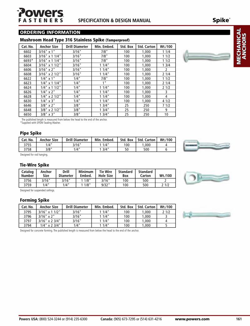
Catalog Anchor Drill Minimum Tie Wire Standard StandardNumber Size Diameter Embed. Hole Size Box Carton Wt./100
3756 3/16" 3/16" 1 1/8" 3/16" 100 500 23759 1/4" 1/4" 1 1/8" 9/32" 100 500 2 1/2
Tie-Wire Spike
Cat. No. Anchor Size Drill Diameter Min. Embed. Std. Box Std. Carton Wt./1006602 3/16" x 1" 3/16" 7/8" 100 1,000 1 1/46603 3/16" x 1 1/4" 3/16" 7/8" 100 1,000 1 1/26693* 3/16" x 1 1/4" 3/16" 7/8" 100 1,000 1 1/26604 3/16" x 1 1/2" 3/16" 1 1/4" 100 1,000 1 3/46606 3/16" x 2" 3/16" 1 1/4" 100 1,000 26608 3/16" x 2 1/2" 3/16" 1 1/4" 100 1,000 2 1/46622 1/4" x 1" 1/4" 7/8" 100 1,000 1 1/26623 1/4" x 1 1/4" 1/4" 1" 100 1,000 2 1/46624 1/4" x 1 1/2" 1/4" 1 1/4" 100 1,000 2 1/26626 1/4" x 2" 1/4" 1 1/4" 100 1,000 36628 1/4" x 2 1/2" 1/4" 1 1/4" 100 1,000 46630 1/4" x 3" 1/4" 1 1/4" 100 1,000 4 1/26646 3/8" x 2" 3/8" 1 3/4" 25 250 7 1/26648 3/8" x 2 1/2" 3/8" 1 3/4" 25 250 96650 3/8" x 3" 3/8" 1 3/4" 25 250 10
ORDERING INFORMATION
Mushroom Head Type 316 Stainless Spike (Tamperproof)
Cat. No. Anchor Size Drill Diameter Min. Embed. Std. Box Std. Carton Wt./1003755 1/4" 3/16" 1 1/4" 100 1,000 43758 3/8" 1/4" 1 3/4" 50 500 6
Pipe Spike
Cat. No. Anchor Size Drill Diameter Min. Embed. Std. Box Std. Carton Wt./1003795 3/16" x 1 1/2" 3/16" 1 1/4" 100 1,000 2 1/23796 3/16" x 2" 3/16" 1 1/4" 100 1,000 33797 3/16" x 2 3/4" 3/16" 1 1/4" 100 1,000 43794 1/4" x 2 3/4" 1/4" 1 1/4" 100 1,000 5
Forming Spike
The published length is measured from below the head to the end of the anchor.*Supplied with EPDM Sealing Washer.
Designed for rod hanging.
Designed for suspended ceilings.
Designed for concrete forming. The published length is measured from below the head to the end of the anchor.
AD
HESIV
ES
MEC
HAN
ICA
LAN
CH
OR
S
WA
LL AN
CH
OR
S
POW
DER
AC
TUA
TED
GA
S FA
STENIN
G
RO
OFIN
G
FASTEN
ERS
CA
RB
IDE
DR
ILL BITS
SPECIFICATION & DESIGN MANUAL Spike®
www.powers.com Canada: (905) 673-7295 or (514) 631-4216 Powers USA: (800) 524-3244 or (914) 235-6300 162
ORDERING INFORMATION
CatalogNumber Tool Description Guide I.D. Standard Box Wt./100
3790 Spike Driver 1000 1/2" 1 1/43791 Spike Driver 2000 1/2" 1 1/43894* Spike Driver 6000 1" 1 1/4
Spike Drivers
CatalogNumber Tool Description Tip O.D. Standard Box Wt./100
3760 Pipe Spike Setting Tool 5/16" 1 1
Pipe Spike Setting Tool
Style Size 1000 2000 6000 PipeMushroom 3/16" X XMushroom 1/4" X XMushroom 3/8" XMushroom 1/2" XFlat Head 3/16" X XFlat Head 1/4" X X
Pipe 1/4" X XPipe 3/8" X X
Tie-Wire 3/16" X XForming 3/16" X XForming 1/4" X X
Spike Driver Selection Guide
*Discontinued item once current stock is exhausted.
© 2006 Powers Fasteners, Inc. All Rights Reserved. Spike is a registered trademark of Powers Fasteners, Inc.
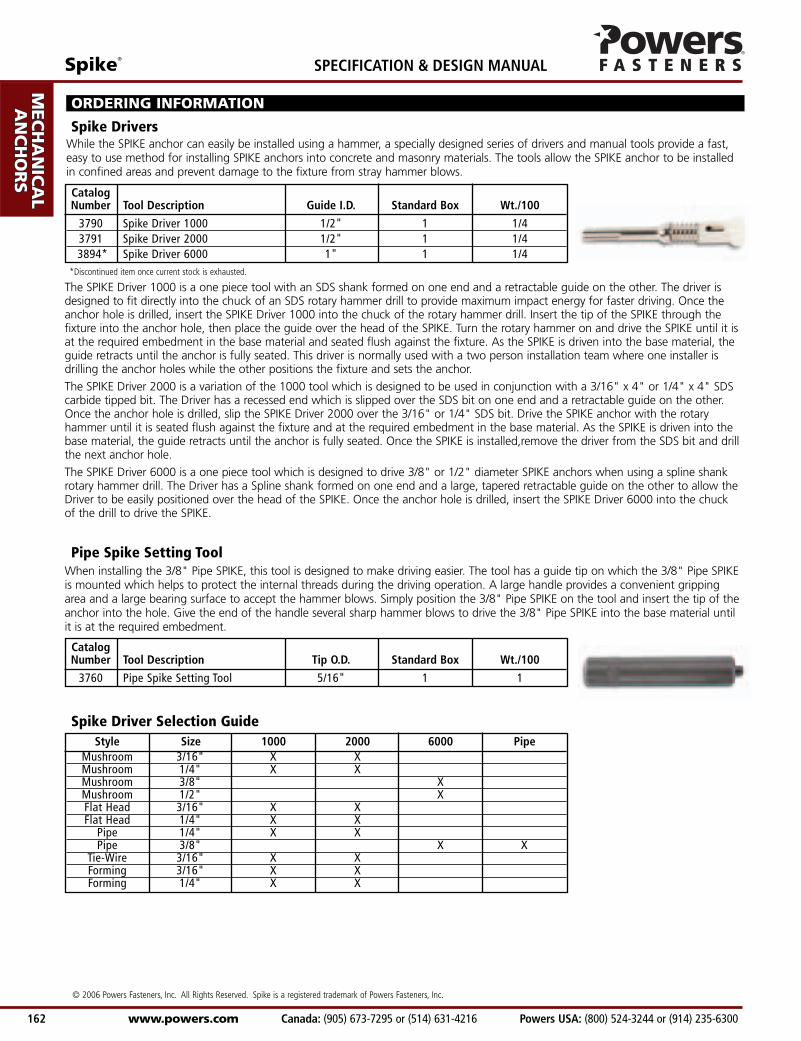
While the SPIKE anchor can easily be installed using a hammer, a specially designed series of drivers and manual tools provide a fast,easy to use method for installing SPIKE anchors into concrete and masonry materials. The tools allow the SPIKE anchor to be installedin confined areas and prevent damage to the fixture from stray hammer blows.
The SPIKE Driver 1000 is a one piece tool with an SDS shank formed on one end and a retractable guide on the other. The driver isdesigned to fit directly into the chuck of an SDS rotary hammer drill to provide maximum impact energy for faster driving. Once theanchor hole is drilled, insert the SPIKE Driver 1000 into the chuck of the rotary hammer drill. Insert the tip of the SPIKE through thefixture into the anchor hole, then place the guide over the head of the SPIKE. Turn the rotary hammer on and drive the SPIKE until it isat the required embedment in the base material and seated flush against the fixture. As the SPIKE is driven into the base material, theguide retracts until the anchor is fully seated. This driver is normally used with a two person installation team where one installer isdrilling the anchor holes while the other positions the fixture and sets the anchor.
The SPIKE Driver 2000 is a variation of the 1000 tool which is designed to be used in conjunction with a 3/16" x 4" or 1/4" x 4" SDScarbide tipped bit. The Driver has a recessed end which is slipped over the SDS bit on one end and a retractable guide on the other.Once the anchor hole is drilled, slip the SPIKE Driver 2000 over the 3/16" or 1/4" SDS bit. Drive the SPIKE anchor with the rotaryhammer until it is seated flush against the fixture and at the required embedment in the base material. As the SPIKE is driven into thebase material, the guide retracts until the anchor is fully seated. Once the SPIKE is installed,remove the driver from the SDS bit and drillthe next anchor hole.
The SPIKE Driver 6000 is a one piece tool which is designed to drive 3/8" or 1/2" diameter SPIKE anchors when using a spline shankrotary hammer drill. The Driver has a Spline shank formed on one end and a large, tapered retractable guide on the other to allow theDriver to be easily positioned over the head of the SPIKE. Once the anchor hole is drilled, insert the SPIKE Driver 6000 into the chuckof the drill to drive the SPIKE.
When installing the 3/8" Pipe SPIKE, this tool is designed to make driving easier. The tool has a guide tip on which the 3/8" Pipe SPIKEis mounted which helps to protect the internal threads during the driving operation. A large handle provides a convenient grippingarea and a large bearing surface to accept the hammer blows. Simply position the 3/8" Pipe SPIKE on the tool and insert the tip of theanchor into the hole. Give the end of the handle several sharp hammer blows to drive the 3/8" Pipe SPIKE into the base material untilit is at the required embedment.