Embed Size (px)
Citation preview

1101 Fawcett Avenue, Suite 200, Tacoma, WA 98402 TELEPHONE: (253) 383-4940, FAX: (253) 383-4923 www.geoengineers.com
EMAIL TRANSMITTAL
Puget Sound EnergyDate: 2/12/2009
Regarding: Upper Baker Generation Plant
To: Lea Boyle
File: 00186-634-03PO Box 90868, EST-06E
Bellevue, Washington 98009-9734
Remarks: Please call if you have questions.
Email Address: [email protected]
Date Description
8/28/2008 Final SPCC Plan (PDF and Word)
DISCLAIMER: This document and any attachments are confidential and intended solely for the use of the individual or entity to whom they are addressed. Any electronic form, facsimile or hard copy of the original document (email, text, table, and/or figure), if provided, and any attachments are only a copy of the original document. The original document is stored by GeoEngineers, Inc. and will serve as the official document of record.
Tony C. [email protected]
Signed: ________________________________________
SPILL PREVENTION, CONTROL AND COUNTERMEASURE PLAN UPPER BAKER GENERATION PLANT 47256 BAKER DAM ROAD CONCRETE, WASHINGTON AUGUST 28, 2008 FOR PUGET SOUND ENERGY
File No. 0186-634-03
August 28, 2008
Puget Sound Energy P.O. Box 90868 PSE-11N Bellevue, Washington 98009-0868
Attention: John Rork
Subject: Spill Prevention, Control and Countermeasure Plan Upper Baker Generation Plant 47256 Baker Dam Road Concrete, Washington File No. 0186-634-03
GeoEngineers is pleased to submit the Spill Prevention, Control and Countermeasure (SPCC) Plan for Puget Sound Energy, Upper Baker Generation Plant, 47256 Baker Dam Road, Concrete, Washington. Our services were completed in general accordance with our agreement with Puget Sound Energy (Contract No. 4600001763).
This SPCC Plan has been prepared for the exclusive use by Puget Sound Energy, their authorized agents and regulatory agencies. This Plan is not intended for use by others, and the information contained herein is not applicable to other sites. Within the limitations of scope, schedule, and budget, our services have been executed in accordance with the generally accepted engineering practices for SPCC plans in this area at the time this Plan was prepared. No warranty or other conditions express or implied should be understood.
We appreciate the opportunity to assist Puget Sound Energy on this project. Please contact us if you have questions regarding this report.
Yours very truly, GeoEngineers, Inc. Kurt R. Fraese, LG Principal
TCM:KRF:tt TACO:\0\0186634\03\Finals\018663403SPCCPlan_UpperBaker.doc


Puget Sound Energy Upper Baker Generation Plant 47256 Baker Dam Road Concrete, Washington 98237
SPILL PREVENTION CONTROL AND COUNTERMEASURE PLAN SPCC PLAN REVIEW AND AMENDMENT
(PART 112.5)
In accordance with 40 CFR Part 112.5(b), a review and evaluation of this SPCC Plan will be conducted at least once every five years. As a result of this review and evaluation, Puget Sound Energy will amend the SPCC Plan within six months of the review to include more effective prevention and control technology if: 1) such technology will significantly reduce the likelihood of a spill event from the facility, and 2) such technology has been field-proven at the time of review. Any amendment to the SPCC Plan shall be certified by a Professional Engineer within six months after a change in the facility design, construction, operation, or maintenance occurs which materially affects the facility’s potential for the discharge of oil into or upon the navigable waters of the United States or adjoining shorelines.
The undersigned individuals have completed a review and evaluation of the SPCC Plan for the Upper Baker Generation Plant, on the indicated date, and will amend the plan as described below.
Designated Person Accountable for
Management Approval for Implementation Spill Prevention Review
Signature: Signature:
Name: John Jensen Name: Edward R. Schild
Title: Manager, Hydro Services Title: Director of Energy Production & Storage
Review Date: Review Date:
Summary of SPCC Plan Amendments
_________________________________________________________________________________
_________________________________________________________________________________
_________________________________________________________________________________
_________________________________________________________________________________
_________________________________________________________________________________
_________________________________________________________________________________
_________________________________________________________________________________
_________________________________________________________________________________
File No. 0186-634-03 Page ii August 28, 2008

Puget Sound Energy Upper Baker Generation Plant 47256 Baker Dam Road Concrete, Washington 98237
File No. 0186-634-03 Page iii August 28, 2008
TABLE OF CONTENTS
Page No.
SPILL PREVENTION CONTROL AND COUNTERMEASURE PLAN MANAGEMENT APPROVAL AND CERTIFICATION................................................................................................................................ i
SPILL PREVENTION CONTROL AND COUNTERMEASURE PLAN SPCC PLAN REVIEW AND AMENDMENT (PART 112.5) ......................................................................................................................ii
1.0 FACILITY INFORMATION AND CONTACTS (PART 112.7) ................................................................ 1 1.1 EMERGENCY CONTACTS AND NOTIFICATIONS (PART 112.7 (A)(3)(VI)) ............................ 1 1.2 SPILL REPORTING PROCEDURES (PART 112.7 (A)(4)) ......................................................... 3 1.3 NON-EMERGENCY FACILITY CONTACTS AND INFORMATION............................................ 4
2.0 REGULATORY AUTHORITY, DEFINITIONS, GENERAL REQUIREMENTS AND PURPOSE OF THE PLAN (PART 112.1, 112.2, 112.3(A) & (B), and 112.7) ............................................................... 5
2.1 PLAN ORGANIZATION AND CROSS REFERENCE (PART 112.7) .......................................... 5
3.0 GENERAL FACILITY DESCRIPTION (PART 112.7) ............................................................................ 8 3.1 COMPLIANCE WITH APPLICABLE SPCC REQUIREMENTS (PARTS 112.7 (A) AND 112.8 (A)) .................................................................................................................................... 8 3.2 LIST OF OIL STORAGE TANKS AND OIL-CONTAINING EQUIPMENT (PART 112.7 (A)(3)(I))................................................................................................................ 9 3.3 DESCRIPTION OF OIL STORAGE AND OIL-CONTAINING EQUIPMENT (PART 112.7 (A)(3)) ................................................................................................................ 11
3.3.1 Generating Plant............................................................................................................ 11 3.3.2 Fuel Island Area ............................................................................................................ 11 3.3.3 Depression Lake Pump Station Area ............................................................................ 12 3.3.4 Glover Mountain Telecommunications Area ................................................................. 12 3.3.5 “Beach 3” Spawning Area.............................................................................................. 12
3.4 DRAINAGE PATHWAYS AND DISTANCE TO NAVIGABLE WATERS (PART 112.8(B)) ....... 12 3.4.1 On-Site Drainage........................................................................................................... 12 3.4.2 Potential Off-Site Drainage Pathways ........................................................................... 13
4.0 POTENTIAL SPILLS AND prevention measures ................................................................................ 14 4.1 FAULT ANALYSIS – POTENTIAL SPILL EVENTS (PART 112.7(B))....................................... 14 4.2 OIL SPILL CONTAINMENT SYSTEMS (PART 112.7(C))......................................................... 15
4.2.1 Generating Plant............................................................................................................ 15 4.2.2 Fuel Island Area ............................................................................................................ 16 4.2.3 Depression Lake Pump Station Area ............................................................................ 16 4.2.4 Glover Mountain Telecommunications Area ................................................................. 17 4.2.5 “Beach 3” Spawning Area.............................................................................................. 17
4.3 INSPECTIONS AND RECORD KEEPING (PART 112.7 (E)) ................................................... 17 4.3.1 Oil Filled Electrical Equipment....................................................................................... 17 4.3.2 Turbine Bearing System, Thrust and Guide at Generating Plant.................................. 18 4.3.3 Pump Bearing Systems at Depression Lake Pump Station Area ................................. 19
Puget Sound Energy Upper Baker Generation Plant 47256 Baker Dam Road Concrete, Washington 98237
File No. 0186-634-03 Page iv August 28, 2008
TABLE OF CONTENTS (CONTINUED)
Page No.
4.3.4 Aboveground Storage Tanks......................................................................................... 19 4.3.5 Miscellaneous Oil Storage Areas .................................................................................. 20
4.4 BRITTLE FRACTURE EVALUATION REQUIREMENTS (PART 112.7 (I)) .............................. 20 4.5 SECURITY (PART 112.7 (G)).................................................................................................... 20
5.0 TRAINING AND DISCHARGE PREVENTION PROCEDURES.......................................................... 21 5.1 TRAINING (PART 112.7 (F)) ..................................................................................................... 21 5.2 OIL LOADING AND HANDLING PROCEDURES (PART 112.7 (A)(3)(III), PART 112.7 (H) AND PART 112.8 (D))........................................................................................................... 21
5.2.1 Transferring Fuel or Oil.................................................................................................. 21 5.2.2 Handling Oil-Filled Equipment....................................................................................... 22
5.3 SIGNS, PLANS AND OIL CONTAINMENT KITS ...................................................................... 22 5.3.1 Oil Spill Notification, Sign, and Plan Location ............................................................... 22 5.3.2 Oil Spill Containment Kits .............................................................................................. 22
6.0 SPILL EVENT: CONTAINMENT AND COUNTERMEASURE PROCEDURES (PART 112.7 (A)(3)(III) AND (IV)) ..................................................................................................... 23
6.1 GENERAL PROCEDURES........................................................................................................ 23 6.1.1 Identification .................................................................................................................. 23 6.1.2 Notification and Emergency Contacts ........................................................................... 23 6.1.3 Containment .................................................................................................................. 23
6.2 CLEANUP AND PCB SPECIAL HANDLING PROCEDURES (PART 112.7 (A)(3)(V)) ............ 24 6.3 ASSESSING THE SPILL EVENT .............................................................................................. 24 6.4 REPORT REQUIREMENTS ...................................................................................................... 25
6.4.1 Form .............................................................................................................................. 25 6.4.2 Notification..................................................................................................................... 25
7.0 CONFORMANCE WITH STATE REQUIREMENTS (PART 112.7 (J)) ............................................... 26
8.0 PLAN AMENDMENT BY THE REGIONAL ADMINISTRATOR (PART 112.4).................................... 27
List of Tables
Table 1. Plan Elements and Cross Reference to 40 CFR (Part 112) .......................................................... 6 Table 2. Non-Electrical Oil-Containing Equipment ..................................................................................... 9 Table 3. Oil-Containing Electrical Equipment ............................................................................................ 10 Table 4. Potential Spill Events (Part 112.7(B)) .......................................................................................... 15
List of Figures
Figure 1. Vicinity Map Figures 2 and 3. Site Plan – Upper Baker Generation Plant Figure 4. Site Plan – Fuel Island Area Figure 5. Depression Lake Pump Station Area

Puget Sound Energy Upper Baker Generation Plant 47256 Baker Dam Road Concrete, Washington 98237
TABLE OF CONTENTS (CONTINUED)
APPENDICES
APPENDIX A – CERTIFICATION OF THE APPLICABILITY OF THE SUBSTANTIAL HARM CRITERIA
APPENDIX B – PSE STANDARDS AND FORMS Oil Spill/SPCC/HAZ – Training Roster PSE Form 1184 – Spill Report Form PSE Form 1185 – Weekly Facility Inspection Form PSE Form 1364 – Monthly/Quarterly Facility Inspection Form PSE Standard Practice 0150.3100 – Cleanup of Oil Spills PSE Standard Practice 0150.3150 – Oil Sampling Procedures for Distribution
Transformers and Oil-Filled Equipment Information Placard On Control Valve for Diked Secondary Containment Area
APPENDIX C – MAINTENANCE AND INSPECTION RECORDS Completed Weekly Facility Inspection Forms Completed Monthly Inspection Forms Completed Quarterly Inspection Forms Oil/Water Separator Maintenance Forms Other Operating Information as Appropriate
File No. 0186-634-03 Page v August 28, 2008

Puget Sound Energy Upper Baker Generation Plant 47256 Baker Dam Road Concrete, Washington 98237
1.0 FACILITY INFORMATION AND CONTACTS (PART 112.7)
The facility described in this Plan is under the primary responsibility of Puget Sound Energy Power Production. All questions relating to this SPCC Plan or facility should be directed to the appropriate contacts listed in this section.
1.1 EMERGENCY CONTACTS AND NOTIFICATIONS (PART 112.7 (A)(3)(VI))
Local Emergency Services Telephone Number: 911 (9-911 from internal phones)
Puget Sound Energy Notifications
Name: Gordie Johnston
Title: Spill Response Coordinator
Contact Information: 24-Hour Spill Pager: (206) 994-3186*
*Contact this Number First in the Event of a Spill
Name: John Jensen
Title: Manager Hydro Services
Contact Information: Telephone: (360) 424-2910 (external)
86-2910 (internal)
Cell Phone: (360) 661-2280
Fax: (425) 462-3118
Name: Lynn Bell
Title: Maintenance Supervisor – Baker River Hydro
Contact Information: Telephone: (360) 853-8341 (external)
86-3042 (internal)
Cell Phone: (360) 305-0674
File No. 0186-634-03 Page 1 August 28, 2008
Puget Sound Energy Upper Baker Generation Plant 47256 Baker Dam Road Concrete, Washington 98237
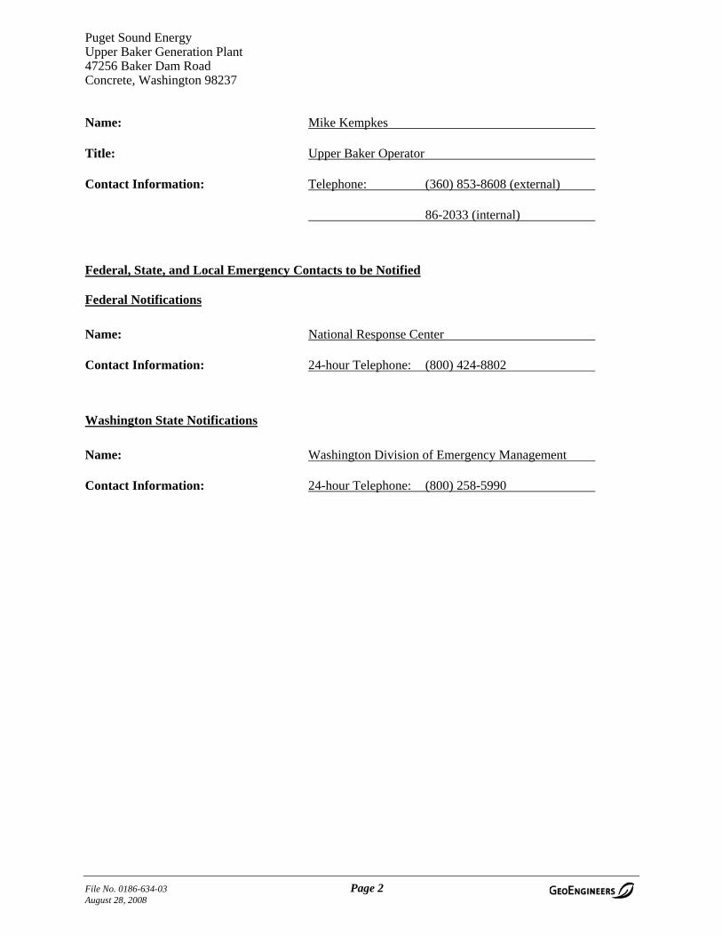
Name: Mike Kempkes
Title: Upper Baker Operator
Contact Information: Telephone: (360) 853-8608 (external)
86-2033 (internal)
Federal, State, and Local Emergency Contacts to be Notified
Federal Notifications
Name: National Response Center
Contact Information: 24-hour Telephone: (800) 424-8802
Washington State Notifications
Name: Washington Division of Emergency Management
Contact Information: 24-hour Telephone: (800) 258-5990
File No. 0186-634-03 Page 2 August 28, 2008
Puget Sound Energy Upper Baker Generation Plant 47256 Baker Dam Road Concrete, Washington 98237
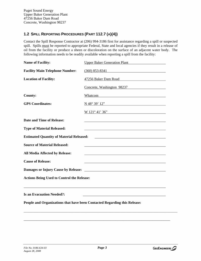
1.2 SPILL REPORTING PROCEDURES (PART 112.7 (A)(4))
Contact the Spill Response Contractor at (206) 994-3186 first for assistance regarding a spill or suspected spill. Spills must be reported to appropriate Federal, State and local agencies if they result in a release of oil from the facility or produce a sheen or discoloration on the surface of an adjacent water body. The following information needs to be readily available when reporting a spill from the facility:
Name of Facility: Upper Baker Generation Plant
Facility Main Telephone Number: (360) 853-8341
Location of Facility: 47256 Baker Dam Road
Concrete, Washington 98237
County: Whatcom
GPS Coordinates: N 48° 39’ 12”
W 121° 41’ 36”
Date and Time of Release:
Type of Material Released:
Estimated Quantity of Material Released:
Source of Material Released:
All Media Affected by Release:
Cause of Release:
Damages or Injury Cause by Release:
Actions Being Used to Control the Release:
Is an Evacuation Needed?:
People and Organizations that have been Contacted Regarding this Release:
_____________________________________________________________________________________
_________________________________________________________________________________
File No. 0186-634-03 Page 3 August 28, 2008

Puget Sound Energy Upper Baker Generation Plant 47256 Baker Dam Road Concrete, Washington 98237
1.3 NON-EMERGENCY FACILITY CONTACTS AND INFORMATION
Facility Owner Facility Operator
Name: Puget Sound Energy Puget Sound Energy Upper Baker Generating Plant
Address: P.O. Box 90868 PSE-11N 47256 Baker Dam Road
City, State: Bellevue, Washington 98009 Concrete, Washington 98237
Telephone: (425) 462-3552 (360) 853-8341
Environmental Services Department
Name: Gordie Johnston
Title: Senior Environmental Scientist, Spill Response Coordinator
Contact Information: Telephone: (360) 340-3716
Pager: (206) 994-3186
Name: John Rork – Puget Sound Energy
Title: Manager – Environmental Services
Contact Information: Telephone: (425) 456-2228
Cell Phone: (360) 340-3718
File No. 0186-634-03 Page 4 August 28, 2008
Puget Sound Energy Upper Baker Generation Plant 47256 Baker Dam Road Concrete, Washington 98237
2.0 REGULATORY AUTHORITY, DEFINITIONS, GENERAL REQUIREMENTS AND PURPOSE OF THE PLAN (PART 112.1, 112.2, 112.3(A) & (B), AND 112.7)
Regulations administered by the United States Protection Agency (EPA), and described in Title 40, Code of Federal Regulations, Part 112, dated July 17, 2002 (40 CFR, Part 112) require owners or operators of oil-handling or storage facilities to have Spill Prevention, Control and Countermeasure (SPCC) Plans in place to prevent the release of oil to navigable waterways. These requirements are applicable to non-transportation-related onshore or offshore facilities engaged in drilling, producing, gathering, storing, processing, refining, transferring, distributing, using, or consuming oil and oil products, which due to their location, could reasonably be expected to discharge oil in quantities that may be harmful into or upon the navigable waters of the United States or adjoining shorelines.
A SPCC Plan is a document that details the equipment, workforce, procedures, and steps to prevent, control, and provide adequate countermeasures to prevent the discharge of oil to navigable waters of the United States. The Plan must be prepared in writing and have the full approval of management at a level to commit the necessary resources to fully implement the Plan.
Oil is defined as oil in any form, including, but not limited to fats, oils, or greases of animal, fish, or marine mammal origin; vegetable oils, including oils from seeds, nuts, fruits, or kernels; and, other oils and greases, including petroleum, fuel oil, sludge, synthetic oils, mineral oils, oil refuse, or oil mixed with wastes other than dredged spoil.
These regulations apply to oil storage or handling facilities that are not transportation related, that have total aboveground oil storage of more than 1,320 gallons, or total belowground storage capacity of more than 42,000 gallons that is not regulated under a state program. Containers of less than 55-gallon capacity are not included in the calculation of the capacity of a facility. This facility exceeds the 1,320 gallon threshold requiring a SPCC Plan.
The compliance deadline for having an SPCC Plan in place that has been certified by a Professional Engineer (PE) and that is in conformance with the 2002 amendments to 40 CFR, Part 112 has been extended by the Environmental Protection Agency (EPA) as of May 2007. The new deadline for a facility SPCC plan to comply with the 2002 amendments to 40 CFR, Part 112 is July 1, 2009.
It is the policy of Puget Sound Energy and its contractors to recognize that oil contamination of the waters of the United States or the State of Washington is harmful. Therefore, it is required that emphasis be placed on oil spill prevention, and that appropriate engineering and safety procedures be used at all times when dealing with oil and its associated equipment.
2.1 PLAN ORGANIZATION AND CROSS REFERENCE (PART 112.7)
This Plan contains the required elements of a SPCC Plan as described in 40 CFR, Part 112. The Plan has been organized to meet the requirement of 40 CFR Part 112.7 (a)(5) that it be readily usable in the event of an emergency. A cross reference of the sections of 40 CFR, Part 112, Subparts A and B to the sections contained in this document is included in this section. This cross reference also lists the facility characteristics that must be described in the Plan.
The requirements of § 112.9 through § 112.15 (portions of Subpart A and Subpart C) are not listed in this table. These requirements are for onshore oil production facilities or for facilities storing and handling
File No. 0186-634-03 Page 5 August 28, 2008
Puget Sound Energy Upper Baker Generation Plant 47256 Baker Dam Road Concrete, Washington 98237
animal or vegetable oils, and are not applicable to this facility. Other information contained in the Plan includes the following:
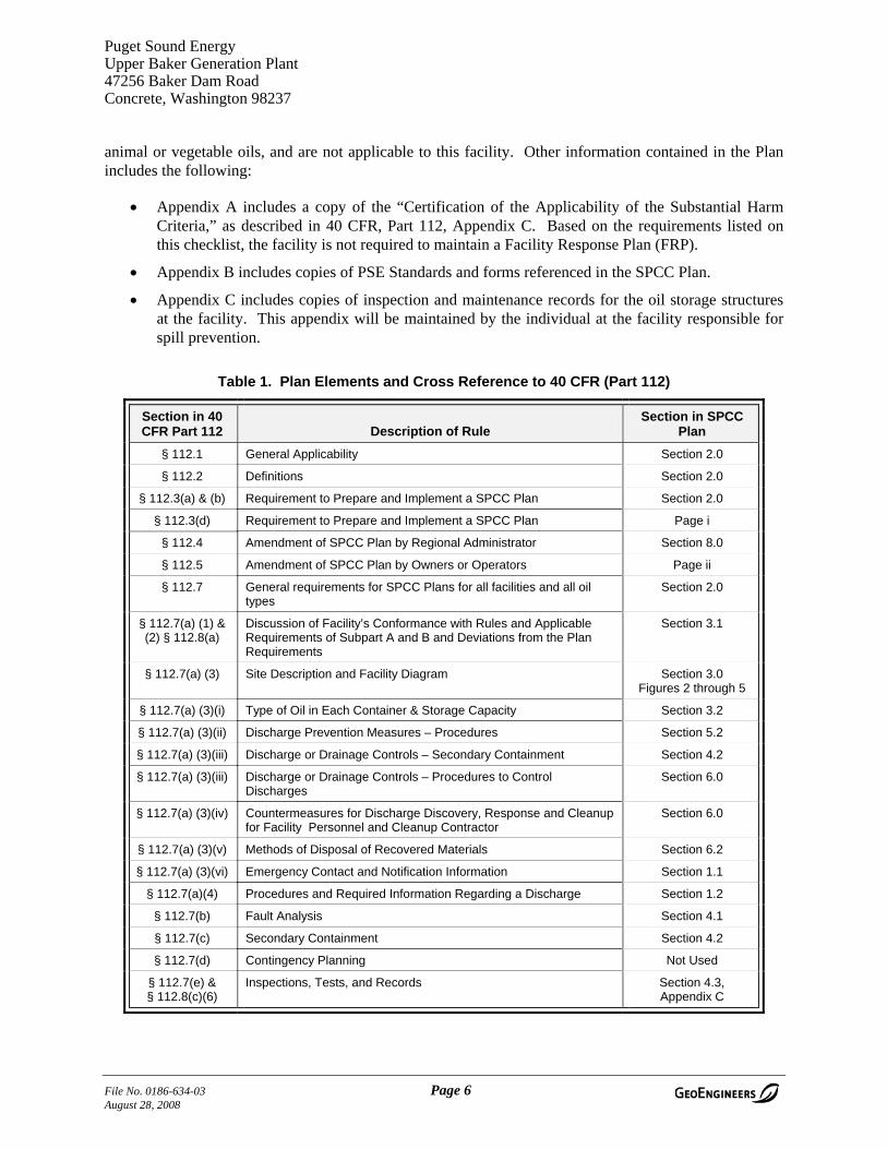
• Appendix A includes a copy of the “Certification of the Applicability of the Substantial Harm Criteria,” as described in 40 CFR, Part 112, Appendix C. Based on the requirements listed on this checklist, the facility is not required to maintain a Facility Response Plan (FRP).
• Appendix B includes copies of PSE Standards and forms referenced in the SPCC Plan.
• Appendix C includes copies of inspection and maintenance records for the oil storage structures at the facility. This appendix will be maintained by the individual at the facility responsible for spill prevention.
Table 1. Plan Elements and Cross Reference to 40 CFR (Part 112)
Section in 40 CFR Part 112 Description of Rule
Section in SPCC Plan
§ 112.1 General Applicability Section 2.0
§ 112.2 Definitions Section 2.0
§ 112.3(a) & (b) Requirement to Prepare and Implement a SPCC Plan Section 2.0
§ 112.3(d) Requirement to Prepare and Implement a SPCC Plan Page i
§ 112.4 Amendment of SPCC Plan by Regional Administrator Section 8.0
§ 112.5 Amendment of SPCC Plan by Owners or Operators Page ii
§ 112.7 General requirements for SPCC Plans for all facilities and all oil types
Section 2.0
§ 112.7(a) (1) & (2) § 112.8(a)
Discussion of Facility’s Conformance with Rules and Applicable Requirements of Subpart A and B and Deviations from the Plan Requirements
Section 3.1
§ 112.7(a) (3) Site Description and Facility Diagram Section 3.0 Figures 2 through 5
§ 112.7(a) (3)(i) Type of Oil in Each Container & Storage Capacity Section 3.2
§ 112.7(a) (3)(ii) Discharge Prevention Measures – Procedures Section 5.2
§ 112.7(a) (3)(iii) Discharge or Drainage Controls – Secondary Containment Section 4.2
§ 112.7(a) (3)(iii) Discharge or Drainage Controls – Procedures to Control Discharges
Section 6.0
§ 112.7(a) (3)(iv) Countermeasures for Discharge Discovery, Response and Cleanup for Facility Personnel and Cleanup Contractor
Section 6.0
§ 112.7(a) (3)(v) Methods of Disposal of Recovered Materials Section 6.2
§ 112.7(a) (3)(vi) Emergency Contact and Notification Information Section 1.1
§ 112.7(a)(4) Procedures and Required Information Regarding a Discharge Section 1.2
§ 112.7(b) Fault Analysis Section 4.1
§ 112.7(c) Secondary Containment Section 4.2
§ 112.7(d) Contingency Planning Not Used
§ 112.7(e) & § 112.8(c)(6)
Inspections, Tests, and Records Section 4.3, Appendix C
File No. 0186-634-03 Page 6 August 28, 2008

Puget Sound Energy Upper Baker Generation Plant 47256 Baker Dam Road Concrete, Washington 98237
Table 1. Plan Elements and Cross Reference to 40 CFR (Part 112) (Continued)
Section in 40 CFR Part 112 Description of Rule
Section in SPCC Plan
§ 112.7(f) Employee Training and Discharge Prevention Procedures Section 5.1
§ 112.7(g) Security (excluding oil production facilities) Section 4.5
§ 112.7(h) Loading/unloading (excluding offshore facilities) Section 5.2
§ 112.7(i) Brittle Fracture Evaluation Requirements Section 4.4
§ 112.7(j) Conformance with State Requirements Section 7.0
§ 112.8(b) Facility Drainage Section 3.4
§ 112.8(c) Bulk Storage Containers Sections 3.3 and 4.2
§ 112.8(d) Fuel Transfer Operations, Pumping & Facility Process Section 5.2
File No. 0186-634-03 Page 7 August 28, 2008
Puget Sound Energy Upper Baker Generation Plant 47256 Baker Dam Road Concrete, Washington 98237
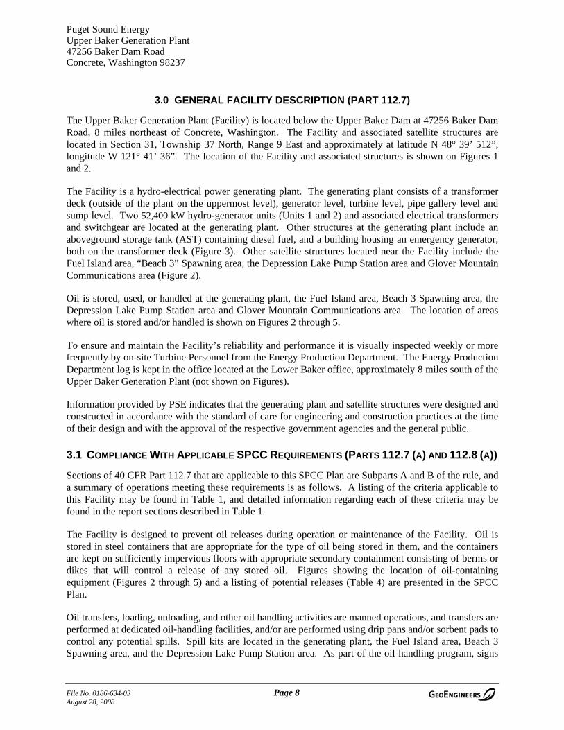
3.0 GENERAL FACILITY DESCRIPTION (PART 112.7)
The Upper Baker Generation Plant (Facility) is located below the Upper Baker Dam at 47256 Baker Dam Road, 8 miles northeast of Concrete, Washington. The Facility and associated satellite structures are located in Section 31, Township 37 North, Range 9 East and approximately at latitude N 48° 39’ 512”, longitude W 121° 41’ 36”. The location of the Facility and associated structures is shown on Figures 1 and 2.
The Facility is a hydro-electrical power generating plant. The generating plant consists of a transformer deck (outside of the plant on the uppermost level), generator level, turbine level, pipe gallery level and sump level. Two 52,400 kW hydro-generator units (Units 1 and 2) and associated electrical transformers and switchgear are located at the generating plant. Other structures at the generating plant include an aboveground storage tank (AST) containing diesel fuel, and a building housing an emergency generator, both on the transformer deck (Figure 3). Other satellite structures located near the Facility include the Fuel Island area, “Beach 3” Spawning area, the Depression Lake Pump Station area and Glover Mountain Communications area (Figure 2).
Oil is stored, used, or handled at the generating plant, the Fuel Island area, Beach 3 Spawning area, the Depression Lake Pump Station area and Glover Mountain Communications area. The location of areas where oil is stored and/or handled is shown on Figures 2 through 5.
To ensure and maintain the Facility’s reliability and performance it is visually inspected weekly or more frequently by on-site Turbine Personnel from the Energy Production Department. The Energy Production Department log is kept in the office located at the Lower Baker office, approximately 8 miles south of the Upper Baker Generation Plant (not shown on Figures).
Information provided by PSE indicates that the generating plant and satellite structures were designed and constructed in accordance with the standard of care for engineering and construction practices at the time of their design and with the approval of the respective government agencies and the general public.
3.1 COMPLIANCE WITH APPLICABLE SPCC REQUIREMENTS (PARTS 112.7 (A) AND 112.8 (A))
Sections of 40 CFR Part 112.7 that are applicable to this SPCC Plan are Subparts A and B of the rule, and a summary of operations meeting these requirements is as follows. A listing of the criteria applicable to this Facility may be found in Table 1, and detailed information regarding each of these criteria may be found in the report sections described in Table 1.
The Facility is designed to prevent oil releases during operation or maintenance of the Facility. Oil is stored in steel containers that are appropriate for the type of oil being stored in them, and the containers are kept on sufficiently impervious floors with appropriate secondary containment consisting of berms or dikes that will control a release of any stored oil. Figures showing the location of oil-containing equipment (Figures 2 through 5) and a listing of potential releases (Table 4) are presented in the SPCC Plan.
Oil transfers, loading, unloading, and other oil handling activities are manned operations, and transfers are performed at dedicated oil-handling facilities, and/or are performed using drip pans and/or sorbent pads to control any potential spills. Spill kits are located in the generating plant, the Fuel Island area, Beach 3 Spawning area, and the Depression Lake Pump Station area. As part of the oil-handling program, signs
File No. 0186-634-03 Page 8 August 28, 2008

Puget Sound Energy Upper Baker Generation Plant 47256 Baker Dam Road Concrete, Washington 98237
are posted to warn personnel to disconnect hoses and secure containers before transport. Potential spill events at the Facility have been summarized, and a prediction of the volume, rate of flow and direction has been prepared.
Discovery of spills will occur quickly. Oil-containing equipment is routinely inspected, typically on a daily basis. Should a catastrophic failure of a piece of electrical equipment or rotating machinery occur at any time, the loss of generating capacity would immediately affect the distribution system. The operators of the distribution system would be able to quickly direct emergency responders to the site in this event.
Cleanup of minor spills would be performed by Facility personnel, whereas major spills would be controlled and cleaned up by qualified contractors. Contact information is detailed at the beginning of this SPCC Plan, and includes appropriate emergency contacts, including Facility personnel, cleanup contractors, and regulatory agencies, and a description of information required during a release is provided.
Inspections and tests are routinely performed on oil-filled equipment and records of these activities are maintained as part of this SPCC Plan. Visual inspection is performed on all oil-filled equipment, and oil-filled pressure vessels are pressure tested in addition to being visually inspected. Smaller non-pressurized oil containers are visually inspected. Nondestructive testing is not performed on these containers as part of normal industry procedures, and because of the low container stresses associated with the typically small volumes of oil used in these non-pressure applications, visual inspection is adequate to evaluate container condition. No field-fabricated oil containers subject to brittle fracture inspection requirements are used at this Facility. Oil-handling personnel receive training regarding the SPCC Plan on an annual basis.
All areas used for oil storage and handling at this Facility are located inside fenced areas.
3.2 LIST OF OIL STORAGE TANKS AND OIL-CONTAINING EQUIPMENT (PART 112.7 (A)(3)(I)) T
The following oil-containing equipment is present at the Facility:
Table 2. Non-Electrical Oil-Containing Equipment (55 gallons or larger)
Oil Storage/Oil-Containing Equipment Quantity
Total Storage Capacity (gallons) Contents
Generating Plant
AST on Transformer Deck 1 100 Diesel
Governor Oil Tanks - Turbine Level 2 1,256 Governor Oil
Turbine Oil Tanks in Oil Storage Room – Turbine Level 2 2,000 New and Used Turbine Oil
Drums/Buckets in Oil Storage Room 10 100-200 Turbine Oil, Hydraulic Oil, Grease, Solvent, Cutting Oil
File No. 0186-634-03 Page 9 August 28, 2008
Puget Sound Energy Upper Baker Generation Plant 47256 Baker Dam Road Concrete, Washington 98237
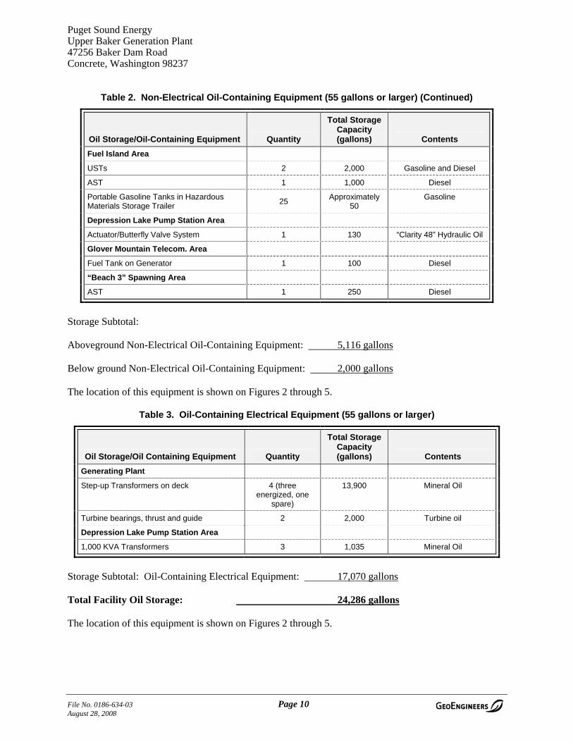
Table 2. Non-Electrical Oil-Containing Equipment (55 gallons or larger) (Continued)
Oil Storage/Oil-Containing Equipment Quantity
Total Storage Capacity (gallons) Contents
Fuel Island Area
USTs 2 2,000 Gasoline and Diesel
AST 1 1,000 Diesel
Portable Gasoline Tanks in Hazardous Materials Storage Trailer 25 Approximately
50 Gasoline
Depression Lake Pump Station Area
Actuator/Butterfly Valve System 1 130 “Clarity 48” Hydraulic Oil
Glover Mountain Telecom. Area
Fuel Tank on Generator 1 100 Diesel
“Beach 3” Spawning Area
AST 1 250 Diesel
Storage Subtotal:
Aboveground Non-Electrical Oil-Containing Equipment: 5,116 gallons
Below ground Non-Electrical Oil-Containing Equipment: 2,000 gallons
The location of this equipment is shown on Figures 2 through 5.
Table 3. Oil-Containing Electrical Equipment (55 gallons or larger)
Oil Storage/Oil Containing Equipment Quantity
Total Storage Capacity (gallons) Contents
Generating Plant
Step-up Transformers on deck 4 (three energized, one
spare)
13,900 Mineral Oil
Turbine bearings, thrust and guide 2 2,000 Turbine oil
Depression Lake Pump Station Area
1,000 KVA Transformers 3 1,035 Mineral Oil
Storage Subtotal: Oil-Containing Electrical Equipment: 17,070 gallons
Total Facility Oil Storage: 24,286 gallons
The location of this equipment is shown on Figures 2 through 5.
File No. 0186-634-03 Page 10 August 28, 2008
Puget Sound Energy Upper Baker Generation Plant 47256 Baker Dam Road Concrete, Washington 98237
3.3 DESCRIPTION OF OIL STORAGE AND OIL-CONTAINING EQUIPMENT (PART 112.7 (A)(3))
3.3.1 Generating Plant
3.3.1.1 Aboveground Storage Tank One 100-gallon double-walled factory fabricated steel AST is located outside on the transformer deck at the generating plant. The tank supplies diesel via aboveground piping to a generator also on the transformer deck. The location of the tank and other oil-containing structures at the generating plant are shown on Figure 3.
3.3.1.2 Governor Oil Tanks Two 628-gallon factory fabricated governor oil tanks are located on the turbine level of the generating plant. The tanks are single-walled pressure vessels that contain governor oil.
3.3.1.3 Turbine Oil Tanks Two 1,000-gallon factory fabricated turbine oil tanks are located in the oil storage room on the turbine level of the generating plant. One tank contains new turbine oil and the other tank contains used turbine oil. The tanks are single-walled steel ASTs. These tanks are only used during generator unit rebuilds, which seldom occur (average every 15 to 30 years).
3.3.1.4 Miscellaneous Oil Storage Typically, two 55-gallon drums containing hydraulic oil and turbine oil are stored on a spill pallet in the oil storage room. Four 5-gallon buckets containing hydraulic oil, grease, cutting oil and solvent and two 15-gallon drums of grease are also located in the oil storage room. Other containers of petroleum-based lubricants may be stored on spill pallets in this area.
3.3.1.5 Step-Up Transformers Four step-up transformers are located east of the powerhouse on the transformer deck. The easternmost transformer is a spare transformer and is not in use. Each transformer contains 3,475 gallons of mineral oil. The locations of the transformers are shown on Figure 3.
3.3.1.6 Grounding Transformers Two turbine grounding transformers are located on the turbine level of the generating plant, one transformer connected to each unit. Each grounding transformer contains 20 gallons of mineral oil.
3.3.2 Fuel Island Area
The locations of the following equipment are indicated on Figure 4.
3.3.2.1 Underground Storage Tanks Two 1,000-gallon underground storage tanks (USTs) containing diesel and gasoline are located underneath a fueling station at the Fuel Island area. The tanks are of double-walled fiberglass construction, with an interstitial leak-detection system designed with an audible alarm in the event of an inner or outer wall breach. The USTs are regulated separately from this SPCC Plan.
3.3.2.2 Aboveground Storage Tanks A 1,000-gallon diesel AST is located west of the Hazardous Materials Storage Trailer. The tank is a double-walled AST with a leak detection system similar to that of the USTs.
File No. 0186-634-03 Page 11 August 28, 2008
Puget Sound Energy Upper Baker Generation Plant 47256 Baker Dam Road Concrete, Washington 98237
3.3.2.3 Hazardous Materials Storage Trailer Approximately 25 portable gasoline tanks, ranging in size from 1 to 6 gallons, are located in the hazardous material storage trailer at the Fuel Island area. The trailer is a factory-fabricated steel trailer built by McKinney Trailer in Seattle, Washington, and is designed with secondary containment integral to the trailer body.
3.3.3 Depression Lake Pump Station Area
The location of the following equipment is indicated on Figure 5.
3.3.3.1 Actuator/Butterfly Valve System A single actuator/butterfly valve system, containing approximately 130 gallons of “Clarity 48” hydraulic oil, is located on the pump station.
3.3.3.2 1,000 kVA Transformers Three 1,000 kVA transformers, each containing 345 gallons of transformer oil, are located in the switchyard at the Pump Station Area.
3.3.4 Glover Mountain Telecommunications Area
3.3.4.1 Diesel Generator A diesel generator with an attached 100-gallon steel fuel tank is located at the Glover Mountain Telecommunications area.
3.3.5 “Beach 3” Spawning Area
A diesel generator with an attached 250-gallon diesel AST is located at the Beach 3 Spawning area.
3.4 DRAINAGE PATHWAYS AND DISTANCE TO NAVIGABLE WATERS (PART 112.8(B))
3.4.1 On-Site Drainage
3.4.1.1 Generating Plant Oil spills on the transformer deck, generator level, turbine level or pipe gallery level all eventually flow to the sump level of the generating plant via drains and pipes. See Section 4.2 for a discussion of transformer deck drainage. The sump has a capacity of 2,660 gallons and is equipped with an oil skimmer and a floating oil detection sensor. The skimmer system continuously removes any oily sheen that may be present in the sump, and collects the oil in a 55-gallon drum next to the sump. The sump pumps water to the dam tailrace. The sump is also visually inspected for oil twice daily by the Facility operators.
The sensor continuously monitors the sump and sounds an alarm if the oil level is 1/4-inch thick or more. The sensor alarm also pages the operator in the event oil is detected in the sump.
The sump pumps stop pumping when the water elevation is approximately 2.75 feet above the floor of the sump, so any accumulation of oil in the sump from a spill would likely trigger an alarm before oil is drawn into the pump system. In the event of a spill, the oil detection system will page the operator, who
File No. 0186-634-03 Page 12 August 28, 2008
Puget Sound Energy Upper Baker Generation Plant 47256 Baker Dam Road Concrete, Washington 98237
will respond within a 30-minute timeframe. The operator may then manually control the pumps from the sump room with the pump starting controls on the pump start boxes
3.4.1.2 Fuel Island Area The Fuel Island area does not have an on-site drainage system. Surface drainage is to the east as described in Section 3.4.2.
3.4.1.3 Depression Lake Pump Station Area Three 1,000 kVA transformers are located within a curbed concrete containment area at the Depression Lake Pump Station area. The concrete containment area drains to a vault located approximately 10 feet northwest of the containment area. The vault is equipped with an oil-stop valve, allowing rainwater to drain to Depression Lake, but automatically closing in the event of an oil spill. Depression Lake is approximately 50 feet north of the vault.
3.4.1.4 Glover Mountain Telecommunications Area The Glover Mountain Telecommunications area does not have an on-site drainage system. Surface drainage is to the north, as described in Section 3.4.2.
3.4.1.5 Beach 3 Spawning Area The Beach 3 Spawning area does not have an on-site drainage system. Surface drainage is to the north as described in Section 3.4.2.
3.4.2 Potential Off-Site Drainage Pathways
3.4.2.1 Generating Plant Potential off-site spills at the generating plant would flow west to the dam tailrace water adjacent to the dam.
3.4.2.2 Fuel Island Area Potential spills at the Fuel Island area would flow east approximately 110 feet to an unlined ditch, which then would flow approximately 400 feet south to the dam tailrace.
3.4.2.3 Depression Lake Pump Station Area Three transformers and a capacitor are located off the northeast and southwest ends of the concrete containment area at the Depression Lake Pump Station area. Potential spills from the transformers or capacitor would flow northwest as overland flow approximately 50 feet to Depression Lake.
The actuator/butterfly valve system and pump bearing systems at the Depression Lake Pump Station are located over/in a vault. Potential spills from the actuator or bearing systems would be contained on the surface of the water in the vault, as the pump low-level is set to keep the water level in the vault above the bottom of the “trash racks” of the vault.
3.4.2.4 Glover Mountain Telecommunications Area Potential spills from the diesel generator at the Glover Mountain Telecommunications area would flow as overland flow toward Depression Lake, approximately 1,600 feet north.
3.4.2.5 ”Beach 3” Spawning Area Potential spills from the AST or diesel generator at the Beach 3 Spawning area would flow north as overland flow approximately 100 feet towards Channel Creek and into Baker Lake.
File No. 0186-634-03 Page 13 August 28, 2008

Puget Sound Energy Upper Baker Generation Plant 47256 Baker Dam Road Concrete, Washington 98237
4.0 POTENTIAL SPILLS AND PREVENTION MEASURES
4.1 FAULT ANALYSIS – POTENTIAL SPILL EVENTS (PART 112.7(B))
The probability of a major uncontrolled oil spill at the Facility or associated satellite structures is low. Although oil storage tanks and several single pieces of electrical equipment contain large quantities of oil, the containment systems at the Facility and associated structures are designed to contain potential spills. Any significant oil spill probably would be caused by a major structural failure. More likely potential spill events would be:
• A slow leak from a piece of stored equipment due to a failed gasket or seal, cracked bushing, or a leaking oil stop plug, fitting, valve or similar item. An event of this nature would be readily detectable during routine inspection or day-to-day activities, and allow ample response time for containment.
• A spill of oil during repair or maintenance of equipment on site. An event of this nature would be quickly detected by the personnel performing the repair or maintenance, and response would be rapid.
Potential spill events at the Facility are summarized in Table 4.
Table 4. Potential Spill Events (Part 112.7(B))
Source Type of Failure Volume
(gallons) Maximum Rate
(gallon/hr) Direction of
Flow Containment
Generating Plant
AST on Transformer Deck
Rupture; leakage 100 100 none Concrete containment
Governor Oil Tanks – Turbine Level
Rupture; leakage 628 628 Towards Sump
Sump
Turbine Oil Tanks in Oil Storage Room – Turbine Level
1,000 1,000 Towards Sump
670-gallon containment /then to sump
Drums/Buckets in Oil Storage Room
Rupture; leakage 55 55 None 670-gallon containment /then to sump
Transformers on deck Rupture; leakage 13,900 13,900 Towards Sump
Containment Vault then to sump
Fuel Island Area
AST Rupture; leakage 1,000 1,000 East to ditch To be replaced with double-walled AST with leak detection
File No. 0186-634-03 Page 14 August 28, 2008

Puget Sound Energy Upper Baker Generation Plant 47256 Baker Dam Road Concrete, Washington 98237
Table 4. Potential Spill Events (Part 112.7(B)) (Continued)
Source Type of Failure Volume
(gallons) Maximum Rate
(gallon/hr) Direction of
Flow Containment Depression Lake Pump Station Area
Pump Bearing Systems Rupture; leakage 60 60 Into Depression Lake
Vault
Actuator/Butterfly Valve System
Rupture; leakage 130 130 Into Depression Lake
Vault
1,000 kVA Transformers
Rupture; leakage 345 345 Into Vault Vault
Glover Mountain Telecom Area
Fuel tank Rupture; leakage 100 100 West None
“Beach 3” Spawning Area
AST Rupture; leakage 250 250 North Fiberglassed Box
4.2 OIL SPILL CONTAINMENT SYSTEMS (PART 112.7(C))
Containment systems for each building and oil storage structure are described in this section.
4.2.1 Generating Plant
The generating plant is a concrete structure at the base of the Upper Baker Dam, which consists of – from top level to bottom – the transformer deck (outside), the generator level, turbine level, pipe gallery level and the sump level (all inside).
4.2.1.1 Transformer Deck Three step-up transformers and a spare step-up transformer, each containing 3,475 gallons of oil, are located on the transformer deck between the generating plant and dam wall. A collection area is located below the three transformers that are in service, and a 6-inch concrete berm around the spare transformer directs flows from around the spare transformer into the collection area. The collection area is filled with washed rock and its containment capacity is negligible. The collection area drains to a trapezoid-shaped containment vault located just below and to the west of the collection area.
The capacity of the vault is approximately 21,600 gallons (155 percent of the total volume of the four step-up transformers combined). The vault drains via enclosed pipe to the sump, and an automatic shutoff valve is located between the vault and sump. The valve closes in the event of a fire or a low-level alarm in the transformers.
The sump has a capacity of approximately 2,660 gallons and drains to the dam tailrace water. The sump is equipped with a floating oil detection sensor. The sensor continuously monitors the sump and sounds an alarm if the oil level is 1/4-inch thick or more. The sensor alarm also pages the operator in the event oil is detected in the sump.
File No. 0186-634-03 Page 15 August 28, 2008

Puget Sound Energy Upper Baker Generation Plant 47256 Baker Dam Road Concrete, Washington 98237
The sump pumps stop pumping when the water elevation is approximately 2.75 feet above the floor of the sump, so any accumulation of oil in the sump from a spill would likely trigger an alarm before oil is drawn into the pump system. In the event of a spill, the oil detection system will page the operator, who will respond within a 30-minute timeframe. The operator may then manually control the pumps from the sump room with the pump starting controls on the pump start boxes.
4.2.1.2 Generator Level Oil spills from equipment on the generator level would flow to the sump level. The sump has a capacity of 2,660 gallons, which is adequate to contain a spill from any individual piece of equipment on the generator level.
4.2.1.3 Turbine Level The oil storage room is located on the turbine level. The oil storage room measures approximately 10 feet by 21 feet, and contains a 5-inch-high berm at the door, for a total secondary containment capacity of 670 gallons. Drums and buckets in the oil storage room are kept on secondary spill containment pallets. A drain in the floor of the oil storage room has been permanently plugged with an expandable rubber plug.
The turbine bearing oil tanks in the oil storage room are each 1,000-gallon-sized tanks, and would overflow the oil storage room containment berm. These and any other spills on the turbine level would flow to the sump level at the generating plant. The sump has 2,660 gallons of containment capacity, which is adequate to contain a spill from any individual piece of equipment on the turbine level.
4.2.1.4 Pipe Gallery Oil spills on the pipe gallery would flow to the sump level. The sump has 2,660 gallons of containment capacity, which is adequate to contain a spill from any individual piece of equipment on the pipe gallery level.
4.2.2 Fuel Island Area
The 1,000-gallon AST at the Fuel Island area is currently housed in temporary secondary containment consisting of a flexible plastic liner that passes underneath the tank and is affixed to the tops of ecology blocks surrounding the tank. Rainwater from the temporary containment is discharged by a 12-volt submersible pump after being checked for oil. The tank is to be replaced with a double-walled 1,000-gallon AST with electronic leak detection in 2006.
The portable gasoline cans are housed in the Hazardous Materials Storage Shed, which is a steel trailer designed as secondary containment.
4.2.3 Depression Lake Pump Station Area
The three 1,000 kVA transformers at the Depression Lake Pump Station area are located on a curbed concrete pad with a capacity of 1,480 gallons, or 143 percent of the total volume of the transformers. The concrete containment area drains to a vault located approximately 10 feet northwest of the containment area. An oil stop valve allows rainwater to drain out of the vault, but closes automatically in the event of an oil release. The vault is routinely inspected for oil. The vault drains to Depression Lake, approximately 50 feet to the north.
File No. 0186-634-03 Page 16 August 28, 2008

Puget Sound Energy Upper Baker Generation Plant 47256 Baker Dam Road Concrete, Washington 98237
4.2.4 Glover Mountain Telecommunications Area
The diesel generator at the Glover Mountain Telecommunications area includes a double-walled 100-gallon fuel tank. The generator sits on a non-curbed concrete pad. Drainage off the pad would be north toward Depression Lake.
4.2.5 “Beach 3” Spawning Area
Both the 250-gallon diesel tank and generator at the Beach 3 Spawning area are housed in secondary containment. The fuel tank is contained in a fiberglassed wood box that has a capacity of 300 gallons (120 percent of the capacity of the fuel tank). The pump is housed in a plastic “collapse-a-tainer” spill containment system. The capacity of the container is 440 gallons, which is significantly greater than the possible oil or diesel capacity of the generator.
4.3 INSPECTIONS AND RECORD KEEPING (PART 112.7 (E))
Inspections of lubrication systems, electrical equipment, and oil storage systems are performed on a regular basis, typically daily when personnel are present. Inspection procedure, any required physical testing of oil-containing equipment and record keeping requirements for oil-containing equipment and stored oil are described in the following subsections.
4.3.1 Oil Filled Electrical Equipment
Oil-filled electrical equipment at the Facility is visually inspected on a weekly basis or more often by Facility personnel for overall condition to include any leaks, damage, or other conditions that could potentially contribute to a release. Inspected equipment includes the following:
• Four transformers on deck at the generating plant
• Two grounding transformers at the generating plant
• Six transformers at the Depression Lake Pump Station area
• Capacitor at the Depression Lake Pump Station area
• Pump butterfly valve/actuator at the Depression Lake Pump Station area
Areas to be inspected include the sides and bottoms of the equipment, and any bushings or plugs on the equipment. These areas are evaluated to see if oil is present, and oil levels are checked using the sight glass in the equipment. Mountings, supports, brackets and bases for oil-filled equipment will be inspected for any damage, deterioration, corrosion or other evidence of potential failure. Any damage or deterioration of the mounting system will be reported to the Maintenance Supervisor for the Facility, and repaired or replaced as necessary.
Any leakage from electrical equipment is noted, and cleaned up with absorbent pads as necessary. These losses and any oil added to the electrical equipment are recorded on a PSE Weekly Facility Inspection Form (Form 1185) or an equivalent form developed by the Facility to evaluate if oil may be leaking from the electrical equipment at some unseen location.
File No. 0186-634-03 Page 17 August 28, 2008

Puget Sound Energy Upper Baker Generation Plant 47256 Baker Dam Road Concrete, Washington 98237
Visual inspection of the oil-filled electrical equipment is the only means of inspection performed on this type of equipment. The equipment is non-pressurized, and other means of testing of the physical integrity of electrical equipment housings are not industry practice. It is our opinion that visual inspection of this equipment is adequate to evaluate its condition.
Any other maintenance and inspection activities will be documented using a PSE Weekly Facility Inspection Form (Form 1185) or an equivalent form developed by the Facility. Copies of the completed inspection form are maintained for a period of 5 years in Appendix C of this SPCC Plan.
4.3.2 Turbine Bearing System, Thrust and Guide at Generating Plant
The turbine bearing system in the generating plant is visually inspected on a regular basis, typically daily, by Facility personnel for leaks and oil levels. Areas to be inspected are piping, piping connections, bearing housings, shaft seals, gasketed joints in oil-filled equipment, lubrication oil pressure vessels and any other oil-filled equipment connected to the turbine lubrication system. Mountings, supports, brackets and bases for oil-filled equipment will be inspected for any damage, deterioration, corrosion or other evidence of potential failure. Any damage or deterioration of the mounting system will be reported to the Maintenance Supervisor for the Facility, and repaired or replaced as necessary
Any leakage from the system is noted, and cleaned up with absorbent pads as necessary. These losses and any oil added to the system are recorded on a PSE Weekly Facility Inspection Form (Form 1185) or an equivalent form developed by the Facility to evaluate if oil may be leaking from the turbine lubrication system at some unseen location. Oil is periodically changed from the system, and oil changes are also documented on an inspection form. Copies of these completed inspection forms are maintained in Appendix C of this SPCC Plan.
The sump at the lower level of the generating plant includes an oil skimmer system, as well as a floating oil detection sensor. The oil skimmer system continuously removes any oily sheen that may be present in the sump, and collects the oil in a 55-gallon drum next to the sump.
The sump is equipped with a floating oil detection sensor. The sensor continuously monitors the sump and sounds an alarm if the oil level is 1/4-inch thick or more. The sensor alarm also pages the operator in the event oil is detected in the sump.
The sump pumps stop pumping when the water elevation is approximately 2.75 feet above the floor of the sump, so any accumulation of oil in the sump from a spill would likely trigger an alarm before oil is drawn into the pump system. In the event of a spill, the oil detection system will page the operator, who will respond within a 30-minute timeframe. The operator may then manually control the pumps from the sump room with the pump starting controls on the pump start boxes.
Pressure vessels that hold reserve oil in the turbine system are pressure tested every 10 years in accordance with American Petroleum Institute (API) 572 to evaluate their suitability for use. Records of this testing provided by the subcontractor performing the testing will be maintained in Appendix C of this SPCC Plan. Pressure testing of the remainder of the lubrication system would likely damage seals and gaskets in the system, and other methods of non-destructive testing would reveal little more information that could be discovered using visual inspection procedures. It is our opinion that visual inspections of the balance of the lubrication system are adequate to evaluate its condition.
File No. 0186-634-03 Page 18 August 28, 2008
Puget Sound Energy Upper Baker Generation Plant 47256 Baker Dam Road Concrete, Washington 98237
Any other maintenance and inspection activities will be documented using a PSE Weekly Facility Inspection Form (Form 1185) or an equivalent form developed by the Facility. Copies of the completed inspection form are maintained for a period of 5 years in Appendix C of this SPCC Plan.
4.3.3 Pump Bearing Systems at Depression Lake Pump Station Area
The pump bearing systems at the Depression Lake Pump Station area are visually inspected on a regular basis, typically daily, by Facility personnel for leaks and oil levels. Areas to be inspected are piping, piping connections, bearing housings, shaft seals, gasketed joints in oil filled equipment, lubrication oil pressure vessels and any other oil filled equipment connected to the pump lubrication systems. Mountings, supports, brackets and bases for oil-filled equipment will be inspected for any damage, deterioration, corrosion or other evidence of potential failure. Any damage or deterioration of the mounting system will be reported to the Maintenance Supervisor for the Facility, and repaired or replaced as necessary
Any leakage from the system is noted, and cleaned up with absorbent pads as necessary. These losses and any oil added to the system are recorded on a PSE Weekly Facility Inspection Form (Form 1185) or an equivalent form developed by the Facility to evaluate if oil may be leaking from the turbine lubrication system at some unseen location. Oil is periodically changed from the system, and oil changes are also documented on an inspection form. Copies of these completed inspection forms are maintained in Appendix C of this SPCC Plan.
4.3.4 Aboveground Storage Tanks
Visual inspections of ASTs are conducted frequently, typically daily, to check for leaks, damage, corrosion or any other conditions that could result in an uncontrolled release of oil. This inspection is documented using a PSE Weekly Facility Inspection Form (Form 1185) or an equivalent form developed by the Facility. Copies of the completed inspection records are kept at the Lower Baker office, approximately 8 miles south of the Upper Baker Generating Plant (not shown on Figures).
4.3.4.1 Generating Plant The following tanks are inspected at the generating plant:
• Two 1,000-gallon new and used turbine oil tanks in the oil storage room on the turbine level
• Two 628-gallon governor oil tanks on the turbine level
• One 100-gallon diesel oil tank on the transformer deck
4.3.4.2 Fuel Island Area The Fuel Island area contains one 1,000-gallon diesel AST that is inspected as described at the beginning of this section. The 250-gallon AST at the Fuel Island area is no longer used for oil storage.
4.3.4.3 “Beach 3” Spawning Area The 250-gallon AST at the Beach 3 Spawning area is inspected as described in Section 4.3.4.
File No. 0186-634-03 Page 19 August 28, 2008
Puget Sound Energy Upper Baker Generation Plant 47256 Baker Dam Road Concrete, Washington 98237
4.3.5 Miscellaneous Oil Storage Areas
Other stored oil and oil-filled equipment at the generating plant or satellite locations is inspected frequently by Facility personnel for overall condition to include any leaks, damage, or other conditions that could potentially contribute to a release.
Visual inspections are performed on stored oil drums, containers, and other oil filled equipment. Areas inspected include the sides and bottoms of the containers, and any drains, fittings or seams in the containers or equipment. If leaks, corrosion dents, or other indications of potential leakage are observed, appropriate action will be taken. Leaking containers will be plugged and/or placed on secondary containment. Containers that have conditions indicative of potential leakage will be placed on secondary containment, and replaced as soon as possible. Any oil will be cleaned up using the procedures described in PSE Standard 0150.3100, “Cleanup of Oil Spills.”
Visual inspection of these types of oil-filled containers (drums and similar non-pressure containers) equipment is the only means of inspection performed on this type of equipment. The equipment is non-pressurized, and other means of testing of the physical integrity of these types of containers are not industry practice. It is our opinion that visual inspection of this equipment is adequate to evaluate its condition.
Inspections are documented using a PSE Weekly Facility Inspection Form (Form 1185) or an equivalent form developed by the Facility. Copies of the completed inspection form are maintained for a period of 5 years in Appendix C of this SPCC Plan.
4.4 BRITTLE FRACTURE EVALUATION REQUIREMENTS (PART 112.7 (I))
The Facility does not use any field constructed aboveground containers. All electrical devices and oil containers used at the Facility are commercially made in a factory environment and are not subject to evaluation for failure by brittle fracture. Should any electrical device or oil container appear to be developing fractures or cracking in its metal case, the device or container will be immediately removed from service.
4.5 SECURITY (PART 112.7 (G))
The Facility is manned 8 hours a day – Monday through Friday, and the operator is within 15 minutes of the plant 24 hours per day, seven days per week.
Measures taken to prevent trespassing, vandalism, and sabotage include, but are not limited to, the following:
• Security fences or water surrounding the Facility site.
• Building and yard lights.
• Warning devices: “Danger” and “No Trespassing” signs.
• Locks on gates and buildings after hours.
• Pump shutoff switches located near the fueling station to shut off pumps in the event of a spill.
File No. 0186-634-03 Page 20 August 28, 2008

Puget Sound Energy Upper Baker Generation Plant 47256 Baker Dam Road Concrete, Washington 98237
5.0 TRAINING AND DISCHARGE PREVENTION PROCEDURES
5.1 TRAINING (PART 112.7 (F))
The Hydro Services Manager or an individual designated by the Hydro Services Manager are responsible for providing an annual training program for Facility personnel regarding SPCC measures.
Spill prevention training will be provided on an annual basis to all personnel that are involved in handling oil. The training program includes the information included in this Plan, methods and procedures used to prevent, control, and clean up an oil spill and a review of pollution control regulations. Training will also include describing any known releases or failures at the Facility, lessons learned from these events, updates on Facility equipment and new precautions to be observed. The following PSE Standards found in Appendix B shall be included as a part of the training:
• 0150.3100, “Cleanup of Oil Spills”
• 0150.3150, “Oil Sampling Procedures for Distribution Transformers and Oil-Filled Equipment”
Other PSE Standards and Specifications also may be included as part of the training. A record of additional standards that are used for training will be maintained in Appendix C.
The examples shown in the Standards are general ways of containing an oil spill. The exact methods employed will depend on local conditions and circumstances. All referenced standards or specifications are attached to this Plan.
Training programs and periodic briefings include review of this Plan and describe actual experiences, recent spill events or failures, and new preventive control and cleanup measures. The individual responsible for training shall maintain a copy of the training roster in Appendix C of this Plan. A sample training roster is included in Appendix B.
5.2 OIL LOADING AND HANDLING PROCEDURES (PART 112.7 (A)(3)(III), PART 112.7(H) AND PART 112.8(D))
It is stressed to all personnel that an essential part of oil spill prevention is being alert for signs of leaks and the prevention of spills during their daily activities. This is accomplished by being observant and by performing regular inspections at the Facility. These inspection procedures, as required by 40 CFR Part 112.8(d)(4) are described in detail in Section 4.3. Leaks or spills shall be immediately reported in accordance with Section 1.1 and the Section 6.1.2 of this document, and appropriate response activities shall be started immediately.
5.2.1 Transferring Fuel or Oil
Tank truck offloading occurs adjacent to the USTs at the Fuel Island area and on the dam structure at the generating plant parking level using a remote fill ports for the oil tanks. No containment has been provided for offloading. Tank truck offloading procedures meet the minimum requirements and regulations of the Washington State Department of Transportation. Truck drivers observe the tank throughout offloading procedures, and drains and outlets on tank trucks are checked for leakage before offloading or departure.
File No. 0186-634-03 Page 21 August 28, 2008

Puget Sound Energy Upper Baker Generation Plant 47256 Baker Dam Road Concrete, Washington 98237
5.2.2 Handling Oil-Filled Equipment
Spill kits will be readily available when handling oil drums and oil-filled equipment. Drums or oil-filled equipment will be sealed, checked for leaks, and if necessary, re-sealed or tightened. Containers or equipment will be properly secured before they are loaded and moved.
5.3 SIGNS, PLANS AND OIL CONTAINMENT KITS
5.3.1 Oil Spill Notification, Sign, and Plan Location
Signs as described in PSE Specification 1275.8100, “In Case of Oil Spill” are be posted along the inside of perimeter fences and in any oil storage or distribution area, and emergency spill contact stickers have been placed on all vehicles at the Facility. Copies of relevant standards are attached to this Plan. The SPCC Plan shall be kept in the following locations:
• The Lower Baker office
• The generating plant
• The Plan originals are kept on file in the Environmental Services Department
5.3.2 Oil Spill Containment Kits
Oil spill equipment and materials are stored in “Small Oil Spill Kits,” which are stored at various locations throughout the Facility. Kits shall be readily accessible and shall not be hidden or covered with other materials or used for anything other than their intended purpose.
Additional kits and materials are available through General Stores.
File No. 0186-634-03 Page 22 August 28, 2008
Puget Sound Energy Upper Baker Generation Plant 47256 Baker Dam Road Concrete, Washington 98237
6.0 SPILL EVENT: CONTAINMENT AND COUNTERMEASURE PROCEDURES (PART 112.7 (A)(3)(III) AND (IV))
6.1 GENERAL PROCEDURES
Containment and countermeasure actions must start immediately after a spill is discovered. The primary objective will be to contain spilled oil within the immediate area, and prevent its entry into the Facility drainage system, the public drainage system or the navigable waters of the United States. This objective shall be met while maintaining proper health and safety procedures. General procedures to be followed in any and all cases of an oil spill event are described below.
6.1.1 Identification
Upon discovery of a spill during normal operations or as a result of an alarm at the Facility, the discoverer shall immediately evaluate whether the spill can be approached safely. From a safe distance, the discoverer shall evaluate the nature and extent of the spill. If possible and safe, the discoverer shall identify the source and stop the leak. The discoverer then shall initiate immediate action to contain the spill, and shall make the notifications described in Section 1.1 or the following section.
6.1.2 Notification and Emergency Contacts
The following notifications shall be made upon discovery of a spill:
• Notify the 24-hour spill response coordinator number (206) 994-3186.
• Notify the Maintenance Supervisor, Upper Baker Operator or designee – phone numbers for the maintenance supervisor are (360) 853-8341, (internal) PSE extension at 86-3042 or cell (360) 853-8608. Phone numbers for the Upper Baker Operator are (360) 853-8608 or internal PSE extension at 86-2033.
• The local fire department shall be notified by the plant operator or designee if there is a potential fire hazard (Phone 911 [external] or 9-911 [internal]).
• The spill response coordinator will advise on procedures for handling the spill. Generally, the spill response coordinator or a spill contractor will respond if a spill meets the following criteria:
The spill is greater than 5 gallons;
The spill enters the Facility drainage system;
The spill is from PCB-containing equipment and affects underlying earth, asphalt or concrete; or
The spill flows off PSE property.
• The spill response coordinator shall contact the appropriate State and Federal agencies as required. The spill response coordinator or Environmental Services shall be the only contact with State and Federal agencies.
6.1.3 Containment
Personnel from the Facility and the cleanup contractor will use the following general actions and PSE guidelines for spill control and containment. Facility personnel will use available spill kits and equipment
File No. 0186-634-03 Page 23 August 28, 2008
Puget Sound Energy Upper Baker Generation Plant 47256 Baker Dam Road Concrete, Washington 98237
stored at the Facility. The spill response coordinator will bring material and equipment as required to control and/or contain the spill. This equipment may be limited to hand tools and sorbent media for any spill that may be reasonably anticipated to occur at this Facility. The spill coordinator or contractors have other equipment available, up to and including heavy earthmoving equipment and watercraft capable of recovering spills from waterways in the event of a catastrophic failure at the Facility.
• Confine and prevent any further spread of the oil (see PSE Standard 0150.3100).
• Plug nearby storm drains. Block catch basins by putting plastic sheeting under the catch basin grates and/or by building diversion dikes of absorbent or other material around the catch basin.
• Reduce or eliminate the spread of oil by using drain system isolation valves, dikes, channels, dams and/or oil absorbent material (see PSE Standard 0150.3100).
• Stop the oil leak at its source, for example:
Plug the leak with available material;
If a transformer or other piece of equipment is leaking, it may be possible to turn it on its side or upside down to raise the point that is leaking; or
If rupture or leak cannot be plugged, use bins, pans, barrels, or containers to catch the oil if possible.
After the spill has been contained, the spill response coordinator will coordinate cleanup of the material.
6.2 CLEANUP AND PCB SPECIAL HANDLING PROCEDURES (PART 112.7 (A)(3)(V))
A representative of the spill coordinator shall coordinate the collection of spilled oil and removal of contaminated soils and other materials. Spilled oil and contaminated media will be transported to PSE’s South King County Waste Management Facility as generally described in Standard 0150.3100. Disposal of spilled oil and contaminated materials shall be arranged at the South King County Waste Management Facility, which is a licensed moderate-risk waste facility (King County Permit Number PR0064285, RCRA ID WAD000006569). Recovered oil, contaminated soil or contaminated water will be disposed of by recycling, thermal treatment and/or land filling at permitted facilities as appropriate.
Special handling is required for a spill event originating from containers or electrical items that are labeled as containing PCB or PCB-contaminated oil. The label used for identifying such containers and items is shown in Standard 0150.3125; cleanup is outlined in Standard 0150.3100 “Cleanup of Oil Spills.” Any oil-filled device of unknown PCB content must be assumed to be PCB contaminated and handled as such. The spill contractor shall be notified when the earth, concrete or asphalt under a leaking PCB-containing device has been contaminated. The spill contractor will verify for adequacy of cleanup.
6.3 ASSESSING THE SPILL EVENT
In accordance with Section 6.1.2, the spill response coordinator shall be notified of the spill event. A spill response contractor shall perform any environmental sampling necessary to evaluate areas affected by the spilled oil, assess and quantify the potential environmental damage, and collect necessary information that may include soil and water samples to confirm that the extent of spilled material has been identified and spilled material has been cleaned up.
File No. 0186-634-03 Page 24 August 28, 2008

Puget Sound Energy Upper Baker Generation Plant 47256 Baker Dam Road Concrete, Washington 98237
6.4 REPORT REQUIREMENTS
6.4.1 Form
Report oil spills using the “Oil Spill Report” form (PSE Form 1184).
6.4.2 Notification
A copy of the Oil Spill Report, including the test results and a map identifying the spill location if prepared, must be forwarded to the Environmental Services Department in a timely fashion. Environmental Services will manage the required State and Federal spill notification and follow-up requirements.
File No. 0186-634-03 Page 25 August 28, 2008

Puget Sound Energy Upper Baker Generation Plant 47256 Baker Dam Road Concrete, Washington 98237
7.0 CONFORMANCE WITH STATE REQUIREMENTS (PART 112.7 (J))
Oil spills in the State of Washington are regulated under the Revised Code of Washington (RCW), Chapters 90.48 and 90.56, which are enforced by the Washington State Department of Ecology (Ecology). RCW 90.48.080 prohibits the discharge of polluting materials into the waters of the State, and RCW 90.56 describes the spill prevention and cleanup process. There is no de minimus release amount defined in these regulations. Rather, any amount of oil that degrades the waters the State constitutes a release. Ecology typically considers the creation of a visible sheen on the water as a spill.
The goal of this Plan is consistent with the objective of RCW 90.48.080, and the items presented in this Plan, including prevention planning, Facility design and operation, spill response and spill notification requirements are in general conformance with the requirements of RCW 90.56. The conformance of the Facility with the requirements of 40 CFR Part 112 as discussed in Section 3.1 of this document addresses the requirements of RCW 90.56.
File No. 0186-634-03 Page 26 August 28, 2008

Puget Sound Energy Upper Baker Generation Plant 47256 Baker Dam Road Concrete, Washington 98237
8.0 PLAN AMENDMENT BY THE REGIONAL ADMINISTRATOR (PART 112.4)
One spill event reportable under Washington State law occurred at the Facility in the past five years. Approximately 20 gallons of diesel fuel and motor oil were released from a diesel-powered water pump at the “Old Spawning Beach” on September 25, 2002. The Old Spawning Beach is located approximately 1,000 feet northwest of the “Beach 3” Spawning Area.
The fuel and oil impacted vegetation and stream banks near the Old Spawning Beach along Channel Creek. The spill was reported to Ecology on the same day the spill occurred (Ecology incident number 529267). Approximately 50 cubic yards of impacted soil and vegetation were removed from the site and disposed of at CSR Associated in Everett, Washington. Chemical analytical results of five confirmation soil samples taken from the limits of the excavation indicated diesel- and lube oil-range hydrocarbons were either not detected or detected at concentrations less than MTCA Method A cleanup levels. In the event of a spill resulting in discharges of more than 1,000 gallons of oil in a single discharge, or more than 42 gallons of oil in each of two discharges occurring in a single year, the following information must be submitted to the EPA Regional Administrator and Ecology for their review within 60 days from the time of such a release or releases(s):
1. Name of the facility;
2. Your name;
3. Location of the facility;
4. Maximum storage or handling capacity of the facility and normal daily throughput;
5. Corrective action and countermeasures you have taken, including a description of equipment repairs and replacements;
6. An adequate description of the facility, including maps, flow diagrams, and topographical maps, as necessary;
7. The cause of discharge, including a failure analysis of the system or subsystem in which the failure occurred;
8. Additional preventive measures you have taken or contemplated to minimize the possibility of recurrence; and
9. Such other information as the Regional Administrator and State Department of Ecology may reasonably require pertinent to the Plan or discharge.
The Plan will be amended, if required after review of the information submitted above by the EPA Regional Administrator or Ecology. The Regional Administrator may require that the Plan be amended if he finds that it does not meet the requirements of this part or that amendment is necessary to prevent and contain discharges from the facility.
File No. 0186-634-03 Page 27 August 28, 2008

§̈¦5
£¤20
£¤530£¤9
£¤525
£¤543
£¤11£¤20
£¤9
£¤20
£¤530
£¤9
WhatcomCounty
WhatcomCounty
SkagitCountySkagitCounty
ChelanCountyChelanCounty
OkanoganCounty
OkanoganCounty
Lambert Conformal ConicWashington State Plane NorthNorth American Datum 1983
Note: This drawing is for informational purposes. It is intended to assistin showing features discussed in an attached document.
Path
:0\0
1866
34\0
0\G
IS\0
1866
3400
_T6_
UB_
FIG
-1.m
xdM
apR
evis
ed:J
une
06,2
005
VICINITY MAP
FIGURE 1
£Data Sources: Interstates, state routes, and roads from TIGER 2000.County boundaries, cities, and waterbodies from Department of Ecology.
All locations are approximate.
It is unlawful to copy or reproduce all or any part thereof, whether for personal use or resale, without permission.
Offi
ce:T
AC
0 6,0003,000Feet
SITESITE
"BEACH 3""BEACH 3"


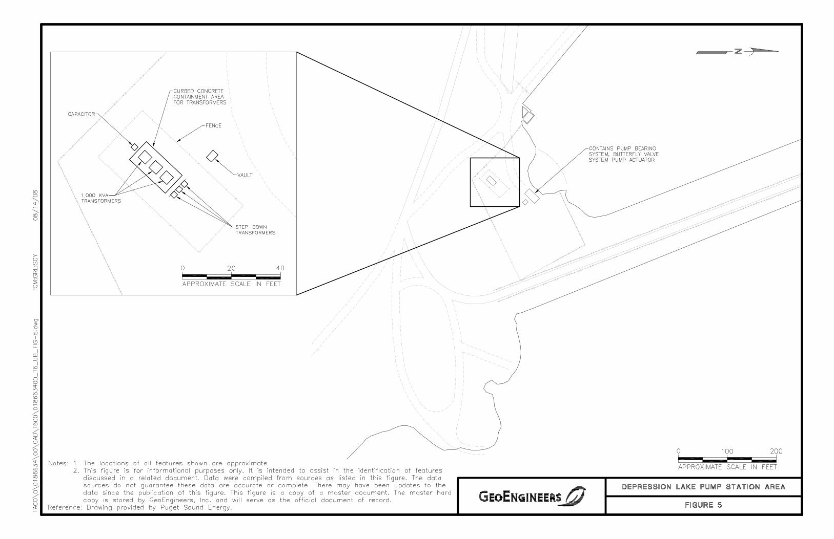

APPENDIX A CERTIFICATION OF THE APPLICABILITY OF THE
SUBSTANTIAL HARM CRITERIA

Puget Sound Energy Upper Baker Generation Plant 47256 Baker Dam Road Concrete, Washington 98237
APPENDIX A CERTIFICATION OF THE APPLICABILITY OF THE
SUBSTANTIAL HARM CRITERIA (FROM 40 CFR, PART 112, APPENDIX C, ATTACHMENT C-II)
Does the facility transfer oil over water to or from vessels and does the facility have a total oil storage capacity greater than or equal to 42,000 gallons?
Yes No
Does the facility have a total oil storage capacity greater than or equal to 1 million gallons and does the facility lack secondary containment that is sufficiently large to contain the capacity of the largest aboveground oil storage tank plus sufficient freeboard to allow for precipitation within any aboveground oil storage tank area?
Yes No
Does the facility have a total oil storage capacity greater than or equal to 1 million gallons and is the facility located at a distance such that a discharge from the facility could cause injury to fish and wildlife and sensitive environments?
Yes No
Does the facility have a total oil storage capacity greater than or equal to 1 million gallons and is the facility located at a distance such that a discharge from the facility would shut down a public drinking water intake?
Yes No
Does the facility have a total oil storage capacity greater than or equal to 1 million gallons and has the facility experienced a reportable oil spill in an amount greater than or equal to 10,000 gallons within the last 5 years.
Yes No
Certification
I certify under penalty of law that I have personally examined and am familiar with the information submitted in this document, and based on my inquiry of those individuals responsible for obtaining this information, I believe that the submitted information is true, accurate and complete.
Signature:
Name: John Jensen
Title: Manager, Hydro Services
File No. 0186-634-03 Page A-1 August 28, 2008

APPENDIX B PSE STANDARDS AND FORMS


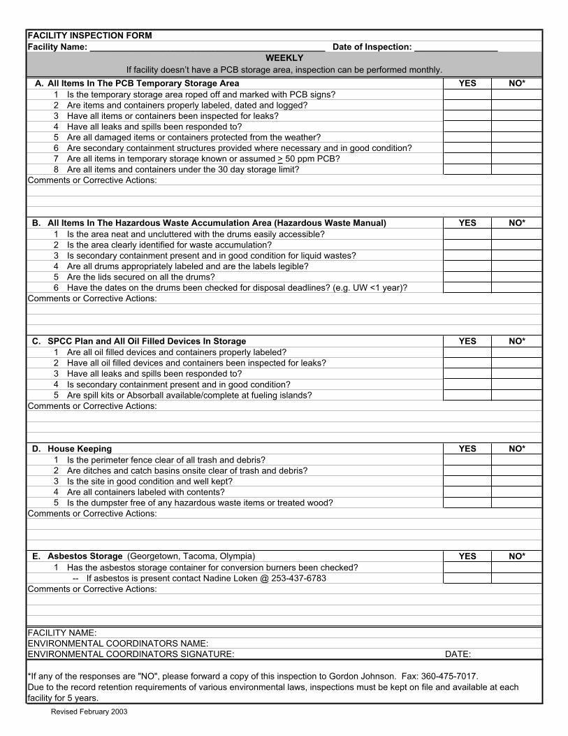
Facility Name: ________________________________________________ Date of Inspection: _________________
A. All Items In The PCB Temporary Storage Area YES NO*1 Is the temporary storage area roped off and marked with PCB signs?2 Are items and containers properly labeled, dated and logged?3 Have all items or containers been inspected for leaks?4 Have all leaks and spills been responded to?5 Are all damaged items or containers protected from the weather? 6 Are secondary containment structures provided where necessary and in good condition?7 Are all items in temporary storage known or assumed > 50 ppm PCB?8 Are all items and containers under the 30 day storage limit?
Comments or Corrective Actions:
B. All Items In The Hazardous Waste Accumulation Area (Hazardous Waste Manual) YES NO*1 Is the area neat and uncluttered with the drums easily accessible?2 Is the area clearly identified for waste accumulation?3 Is secondary containment present and in good condition for liquid wastes?4 Are all drums appropriately labeled and are the labels legible?5 Are the lids secured on all the drums?6 Have the dates on the drums been checked for disposal deadlines? (e.g. UW <1 year)?
Comments or Corrective Actions:
C. SPCC Plan and All Oil Filled Devices In Storage YES NO*1 Are all oil filled devices and containers properly labeled?2 Have all oil filled devices and containers been inspected for leaks?3 Have all leaks and spills been responded to?4 Is secondary containment present and in good condition?5 Are spill kits or Absorball available/complete at fueling islands?
Comments or Corrective Actions:
D. House Keeping YES NO*1 Is the perimeter fence clear of all trash and debris?2 Are ditches and catch basins onsite clear of trash and debris?3 Is the site in good condition and well kept?4 Are all containers labeled with contents?5 Is the dumpster free of any hazardous waste items or treated wood?
Comments or Corrective Actions:
E. Asbestos Storage (Georgetown, Tacoma, Olympia) YES NO*1 Has the asbestos storage container for conversion burners been checked?
-- If asbestos is present contact Nadine Loken @ 253-437-6783Comments or Corrective Actions:
FACILITY NAME:ENVIRONMENTAL COORDINATORS NAME:ENVIRONMENTAL COORDINATORS SIGNATURE: DATE:
*If any of the responses are "NO", please forward a copy of this inspection to Gordon Johnson. Fax: 360-475-7017.
FACILITY INSPECTION FORM
WEEKLY
Due to the record retention requirements of various environmental laws, inspections must be kept on file and available at each facility for 5 years.
If facility doesn’t have a PCB storage area, inspection can be performed monthly.
Revised February 2003


Cleanup of Oil Spills 0150.3100
Effective on: 07/01/07Canceling: 08/01/06
Page 1 of 23
�1998 Puget Sound Energy, Inc.
This standard covers Puget Sound Energy’s procedures for responding to oil spills.
In This Standard
These topics are covered in this standard:
Topic See Page
Definitions 2
Responding to an Oil Spill 2
Responsibilities 3
Safety and Handling 4
Personal Protective Equipment 5
First Aid 5
Industrial Injury and Illness 6
Tools, Materials, and Equipment 6
Spill Response 9
Oil Spill Notification 11
Spill Characterization 13
Spill Cleanup 14
Cleanup Guidelines for Specific Circumstances 14
Decontamination of Equipment 20
Vactor Truck Waste Accumulation, Transport, and Disposal 20
Record Keeping 21
These procedures are required by law and shall be followed by both Puget SoundEnergy employees and contract labor crews. Failure to do so could result in citationsor fines for noncompliance.
Scope
WARNING!
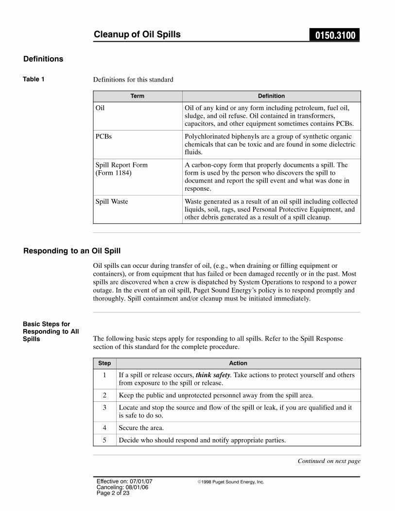
Cleanup of Oil Spills 0150.3100
Effective on: 07/01/07Canceling: 08/01/06Page 2 of 23
�1998 Puget Sound Energy, Inc.
Definitions
Definitions for this standard
Term Definition
Oil Oil of any kind or any form including petroleum, fuel oil,sludge, and oil refuse. Oil contained in transformers,capacitors, and other equipment sometimes contains PCBs.
PCBs Polychlorinated biphenyls are a group of synthetic organicchemicals that can be toxic and are found in some dielectricfluids.
Spill Report Form(Form 1184)
A carbon-copy form that properly documents a spill. Theform is used by the person who discovers the spill todocument and report the spill event and what was done inresponse.
Spill Waste Waste generated as a result of an oil spill including collectedliquids, soil, rags, used Personal Protective Equipment, andother debris generated as a result of a spill cleanup.
Responding to an Oil Spill
Oil spills can occur during transfer of oil, (e.g., when draining or filling equipment orcontainers), or from equipment that has failed or been damaged recently or in the past. Mostspills are discovered when a crew is dispatched by System Operations to respond to a poweroutage. In the event of an oil spill, Puget Sound Energy’s policy is to respond promptly andthoroughly. Spill containment and/or cleanup must be initiated immediately.
The following basic steps apply for responding to all spills. Refer to the Spill Responsesection of this standard for the complete procedure.
Step Action
1 If a spill or release occurs, think safety. Take actions to protect yourself and othersfrom exposure to the spill or release.
2 Keep the public and unprotected personnel away from the spill area.
3 Locate and stop the source and flow of the spill or leak, if you are qualified and itis safe to do so.
4 Secure the area.
5 Decide who should respond and notify appropriate parties.
Continued on next page
Table 1
Basic Steps forResponding to AllSpills

Cleanup of Oil Spills 0150.3100
Effective on: 07/01/07Canceling: 08/01/06
Page 3 of 23
�1998 Puget Sound Energy, Inc.
Tests have shown that oil from some transformers, capacitors, and other electrical equipmentmay contain Polychlorinated Biphenyls (PCBs). The Environmental Protection Agency(EPA) has many requirements for the management of PCBs under the Toxic SubstancesControl Act (TSCA), which addresses the manufacturing, processing, distribution incommerce, use, cleanup, storage, and disposal of PCBs.
Who to call for help
Contact Phone
Environmental Services 24-hr Spill Pager (206) 994-3186
Environmental Services Waste ManagementFacility
(360) 340-3716 or (253) 437-6783
Safety Department Contact Eastside System Operations
Responsibilities
Employees with vehicles that transport oil or oil-filled equipment must carry equipment forcleaning up minor spills.
The employee who discovers or is first notified of the spill is responsible for coordinatinginitial response.
Responsible for determining whether the cleanup is to be completed by the Line/Wire Crewor coordinated by Environmental Services, who will request assistance from one or morespill response consultants.
Internal spill reporting is to be handled in accordance with Table 7.
The Crew Foreman is responsible for:
� Coordinating and monitoring the spill cleanup activities.
� Submitting a draft Spill Report Form (Form 1184) to their Supervisor and EnvironmentalServices.
Either the Crew Foreman or spill response consultant, (under the direction of EnvironmentalServices) is responsible for:
� Decontaminating equipment.
� Accumulating, labeling, and packaging spill waste and out-of-service equipment andtransporting it to the nearest Service Center or other approved storage area in accordancewith Standard 0150.3125.
The Supervisor is responsible for submitting the completed Spill Report Form (Form 1184)to Environmental Services.
Line/Wire Crew employees involved in spill sampling or cleanup are responsible for wearingthe appropriate personal protective equipment (PPE).
Continued on next page
Spills CouldContain PCBs
Table 2
Employees
Supervisor, CrewForeman, andSystem Operations
If Cleanup isHandled byLine/Wire Crew

Cleanup of Oil Spills 0150.3100
Effective on: 07/01/07Canceling: 08/01/06Page 4 of 23
�1998 Puget Sound Energy, Inc.
Responsibilities, Continued
If a vactor truck is called to respond, the Vactor Truck Operator must verify with the CrewForeman the PCB content of the oil that was released prior to beginning work.
The Vactor Truck Operator is also responsible for:
� Contacting the South King Waste Management Facility to coordinate disposal of vactortruck wastes. The operator should ensure that the PCB concentration of the source oil isknown prior to disposing any vactor truck load.
� Completing the logbook and giving a copy of the Spill Report Form (Form 1184) to theWaste Management Facility (WMF) personnel. The WMF personnel are responsible forprocessing the discharged load.
The Environmental Services spill response consultant is responsible for:
� Mobilizing spill response contractors (if necessary) to spill site.
� Coordinating and monitoring the spill cleanup activities.
� Documenting the spill and cleanup activities in Spill Report Form (Form 1184).
Environmental Services, or when requested, their spill response consultant is responsible for:
� Any external reporting required, depending on the spill.
� Determining the probable PCB concentration of the oil spilled if it was from electricalequipment.
� Conducting and documenting any sampling of the equipment and/or site that may benecessary.
The Manager of Environmental Services is responsible for maintaining PSE’s overallcompliance with the applicable environmental regulations.
Safety and Handling
Oil and oil-contaminated materials are potentially hazardous. Sometimes oil contains PCBs.This section describes the personal protective equipment that should be worn during oil spillresponse and first aid procedures that should be used to help anyone who has come intocontact with PCB-containing oil.
Two very important safety tips to remember:
� If there is fire, keep away from the area and protect yourself from inhaling smoke orvapors. Vapors generated during the burning of PCBs can present a serious health risk.
� Avoid direct skin contact with electrical equipment fluids and soot.
Wear personal protective clothing and equipment during all phases of spill cleanup.
Vactor Trucks atCleanup Site
If Cleanup isHandled byEnvironmentalServices
EnvironmentalServices and/orConsultant
Manager ofEnvironmentalServices
CAUTION!

Cleanup of Oil Spills 0150.3100
Effective on: 07/01/07Canceling: 08/01/06
Page 5 of 23
�1998 Puget Sound Energy, Inc.
Personal Protective Equipment� Personal protective equipment (PPE) is to be worn during all phases of oil sampling and
spill cleanup. This includes safety glasses, gloves, coveralls and shoe covers. See theTools, Materials, and Equipment section of this standard for a list of appropriate PPE.
� When liquids are handled in an enclosed area, use a respirator. Wear a face shield to protectfrom liquid splatter.
� Consider sealing your coveralls to your boots with tape.
First Aid
If eyes, skin or clothing come in contact with PCBs or if PCBs are ingested or inhaled,follow these first aid treatments. If medical assistance is necessary, call 911 or take employeeto the hospital and have the Supervisor contact the Safety Department immediately.
If clothing comes in contact with PCBs:
Step Action
1 Remove contaminated clothing as soon as possible.
2 Place clothing in a plastic bag; seal and label it.
3 Place bags in a drum.
4 Notify the area Environmental Coordinator of the location of the drum for properdisposal.
If eyes come in contact with PCBs:
� Flush eyes with water or eye irrigation solution for at least 15 minutes and take employeeto emergency care.
NOTE: If flushing does not relieve symptoms, continue flushing on the way to emergencycare.
If PCBs are ingested:
� The employee is to be taken to the hospital immediately.
� Contact the Safety Department immediately.
If PCBs are inhaled:
� If nausea, breathing difficulty or dizziness occurs, the employee is to be taken to thehospital immediately.
� Contact the Safety Department immediately.
Continued on next page
Clothing Contact
Eye Contact
Ingestion
Inhalation
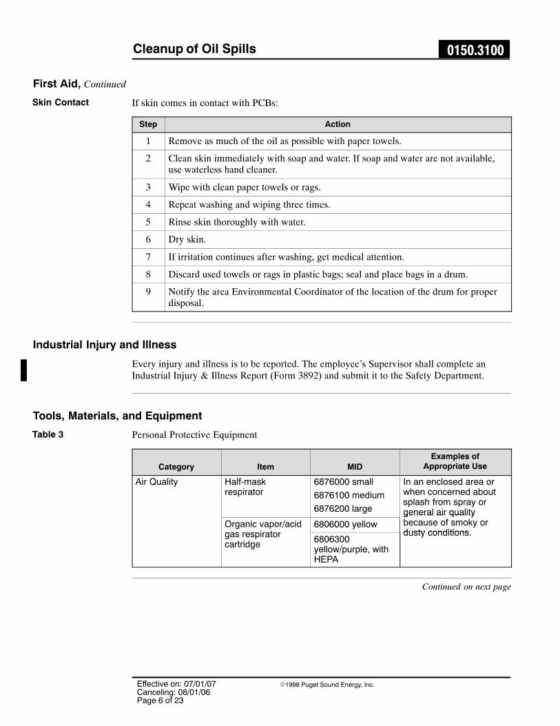
Cleanup of Oil Spills 0150.3100
Effective on: 07/01/07Canceling: 08/01/06Page 6 of 23
�1998 Puget Sound Energy, Inc.
First Aid, Continued
If skin comes in contact with PCBs:
Step Action
1 Remove as much of the oil as possible with paper towels.
2 Clean skin immediately with soap and water. If soap and water are not available,use waterless hand cleaner.
3 Wipe with clean paper towels or rags.
4 Repeat washing and wiping three times.
5 Rinse skin thoroughly with water.
6 Dry skin.
7 If irritation continues after washing, get medical attention.
8 Discard used towels or rags in plastic bags; seal and place bags in a drum.
9 Notify the area Environmental Coordinator of the location of the drum for properdisposal.
Industrial Injury and Illness
Every injury and illness is to be reported. The employee’s Supervisor shall complete anIndustrial Injury & Illness Report (Form 3892) and submit it to the Safety Department.
Tools, Materials, and Equipment
Personal Protective Equipment
Category Item MIDExamples of
Appropriate UseÁÁÁÁÁÁÁÁÁÁÁÁÁÁÁÁÁÁÁÁÁÁÁÁÁÁÁÁÁÁÁÁÁÁÁÁÁÁÁÁÁÁÁÁÁÁÁÁÁÁÁÁÁÁÁÁ
Air QualityÁÁÁÁÁÁÁÁÁÁÁÁÁÁÁÁÁÁÁÁÁÁÁÁÁÁÁÁÁÁÁÁ
Half-maskrespirator
ÁÁÁÁÁÁÁÁÁÁÁÁÁÁÁÁÁÁÁÁÁÁÁÁÁÁÁÁ
6876000 small
6876100 medium
6876200 large
ÁÁÁÁÁÁÁÁÁÁÁÁÁÁÁÁÁÁÁÁÁÁÁÁÁÁÁÁÁÁÁÁÁÁÁÁ
In an enclosed area orwhen concerned aboutsplash from spray orgeneral air qualityÁÁÁÁÁÁÁÁ
ÁÁÁÁÁÁÁÁÁÁÁÁÁÁÁÁÁÁÁÁÁÁÁÁÁÁÁÁÁÁÁÁ
Organic vapor/acidgas respiratorcartridge
ÁÁÁÁÁÁÁÁÁÁÁÁÁÁ6806000 yellow
ÁÁÁÁÁÁÁÁÁÁÁÁÁÁÁÁÁÁ
general air qualitybecause of smoky ordusty conditionsÁÁÁÁÁÁÁ
ÁÁÁÁÁÁÁÁÁÁÁÁÁÁÁÁÁÁÁÁÁ
6806300yellow/purple, withHEPA
ÁÁÁÁÁÁÁÁÁÁÁÁÁÁÁÁÁÁÁÁÁÁÁÁÁÁÁÁÁÁÁÁÁÁÁÁ
dusty conditions.
Continued on next page
Skin Contact
Table 3

Cleanup of Oil Spills 0150.3100
Effective on: 07/01/07Canceling: 08/01/06
Page 7 of 23
�1998 Puget Sound Energy, Inc.
Category Item MIDExamples of
Appropriate Use
Eye Protection Face shield 6829000nonhard hat
6830000hat-mounted
6888000
When transferring liquidsfrom containment into adrum or between drumsany time splash couldoccur or when air isdusty.
Goggles 6827300
Safety glasses withside shields
6827000
6827101
First Aid Portable eye washkit
6826400 If liquids contact the eyeor eyelid.
Waterless handcleaner
4461001 To clean skin areas otherthan eyes.
Hand Protection Gloves Nitrile 6857900Size 9 (15 mil)
6858000Size 10 (15 mil)
When hand contact withliquids is possible, (e.g.,handling leaking orcontaminated equipment,soil, or surfaces).
Skin and ClothingProtection
Disposablecoveralls, rated forhazardousmaterials
6811000 small
6811100 medium
6811200 large
6811300 extra large
Strenuous cleanup, suchas for a large oil spillfrom ruptured equipment.
Disposablecoveralls, Tyvek
6810600 small
6810700 large
6810800 extra large
Nonstrenuous cleanup,short-term exposure,dusty environment.
Skin and ShoeProtection
Disposable shoecovers
6811500 medium
6811600 extra large
6811700 giant
All cleanup operations.
Labels and forms
Category Item MIDExamples of
Appropriate Use
Injuries andIllnesses
Employee InjuryPacket
Available from PSESupervisor
When there is an injuryor illness because of thespill.
Spill Reporting Spill Report Form(Form 1184)
All spills.
NOTE: Other tools and materials are required for waste packaging and labeling, inaccordance with Standard 0150.3125.
Continued on next page
Table 4

Cleanup of Oil Spills 0150.3100
Effective on: 07/01/07Canceling: 08/01/06Page 8 of 23
�1998 Puget Sound Energy, Inc.
Tools, Materials, and Equipment, Continued
Example of Spill Report Form (Form 1184)Figure 1

Cleanup of Oil Spills 0150.3100
Effective on: 07/01/07Canceling: 08/01/06
Page 9 of 23
�1998 Puget Sound Energy, Inc.
Spill response equipment
Category Item MIDExamples of
Appropriate Use
ÁÁÁÁÁÁÁÁÁÁÁÁÁÁÁÁÁÁÁÁÁÁÁÁÁÁÁÁÁÁÁÁÁÁÁÁÁÁÁÁÁÁÁÁÁÁÁÁÁÁÁÁÁÁÁÁÁÁÁÁÁÁÁ
Cleaning ÁÁÁÁÁÁÁÁÁÁÁÁÁÁÁÁ
Absorbent granulesÁÁÁÁÁÁÁÁÁÁÁÁÁÁ
4460800 ÁÁÁÁÁÁÁÁÁÁÁÁÁÁÁÁÁÁ
Capturing small amountsof free liquids.
ÁÁÁÁÁÁÁÁÁÁÁÁÁÁÁÁÁÁÁÁÁÁÁÁ
BroomsÁÁÁÁÁÁÁÁÁÁÁÁÁÁÁÁÁÁÁÁÁ
ÁÁÁÁÁÁÁÁÁÁÁÁÁÁÁÁÁÁÁÁÁÁÁÁÁÁÁ
Sweeping usedabsorbent into piles.
ÁÁÁÁÁÁÁÁÁÁÁÁÁÁÁÁÁÁÁÁÁÁÁÁ
Oil-absorbentsheets
ÁÁÁÁÁÁÁÁÁÁÁÁÁÁÁÁÁÁÁÁÁ
7482500ÁÁÁÁÁÁÁÁÁÁÁÁÁÁÁÁÁÁÁÁÁÁÁÁÁÁÁ
Capturing small amountsof free liquids.
ÁÁÁÁÁÁÁÁÁÁÁÁÁÁÁÁ
Rags ÁÁÁÁÁÁÁÁÁÁÁÁÁÁ
7474500 ÁÁÁÁÁÁÁÁÁÁÁÁÁÁÁÁÁÁ
Wiping down equipment.ÁÁÁÁÁÁÁÁÁÁÁÁÁÁÁÁÁÁÁÁÁÁÁÁ
Shovels ÁÁÁÁÁÁÁÁÁÁÁÁÁÁÁÁÁÁÁÁÁ
ÁÁÁÁÁÁÁÁÁÁÁÁÁÁÁÁÁÁÁÁÁÁÁÁÁÁÁ
Shoveling wastes intodrums.
ÁÁÁÁÁÁÁÁÁÁÁÁÁÁÁÁÁÁÁÁÁÁÁÁÁÁÁÁ
Sampling ÁÁÁÁÁÁÁÁÁÁÁÁÁÁÁÁÁÁÁÁÁÁÁÁ
Chain of CustodyReport (Form 1257)
ÁÁÁÁÁÁÁÁÁÁÁÁÁÁÁÁÁÁÁÁÁ
ÁÁÁÁÁÁÁÁÁÁÁÁÁÁÁÁÁÁÁÁÁÁÁÁÁÁÁ
For all samples of thesite or spill wastes.
ÁÁÁÁÁÁÁÁÁÁÁÁÁÁÁÁ
Oil samplecollection kits
ÁÁÁÁÁÁÁÁÁÁÁÁÁÁ
7408600 ÁÁÁÁÁÁÁÁÁÁÁÁÁÁÁÁÁÁ
Sampling oil in damagedelectric equipment.
NOTE: Other tools and materials are required for waste packaging and labeling, inaccordance with Standard 0150.3125.
Spill Response
This section covers the procedure for responding to and cleaning up oil spills.
For spills, the sooner containment/cleanup is initiated, the more effective it will be.
Step Action
1 If a spill or release occurs, THINK SAFETY. Take actions to protect yourself andothers from exposure to the spill or release.� Drive cautiously when approaching and leaving a spill site.� Avoid driving through the spill area. Oil spread by traffic expands the area of
contamination.� If there is a fire, maintain a safe distance from it.� Ensure that all the equipment involved is de-energized.� Assume all oil contains PCBs until proven otherwise.� Use the proper PPE.
� Protect yourself from skin contact.
� Prevent contamination of clothing.
2 Keep the public and unprotected personnel away from the spill area.
Continued on next page
Table 5
Discovery and FirstSteps

Cleanup of Oil Spills 0150.3100
Effective on: 07/01/07Canceling: 08/01/06Page 10 of 23
�1998 Puget Sound Energy, Inc.
Spill Response, Continued
Step Action
3 Locate and stop the source and flow of the spill or leak, if you are qualified and itis safe to do so.� If leaking cannot be stopped, place a container (bucket, plastic bag, absorbent
pads, kitty litter, or whatever is available) beneath the leak to prevent continuedmigration of oil away from the spill area.
� Divert the oil flow to prevent the spill from entering nearby water bodies or floordrains. Give first priority to spills that could or have endanger(ed) water sources.
� If safe to do so, plug holes, reposition the equipment and/or shut valves.� Use whatever materials and equipment are available to confine the spill and
prevent further contamination of the area. Do not wait for a spill containment kitto arrive.
4 Secure the area.� Use barricades or warning tape to form an adequate buffer around and beyond
any visible traces of oil. A spill in a vault does not require barricading or tape.� If cleanup is delayed, the area shall remain barricaded. Cover the spill with
plastic sheeting.� Limit the number of people entering the spill area.
5 Decide who should respond and notify appropriate parties.
Line/Wire Crews may either clean up the spill themselves according to this standard or mayrequest assistance by calling the Environmental Services 24-Hour Spill Pager (see Table 2).
This decision is made by the Crew Foreman, Supervisor, or System Manager in accordancewith the guidelines in Table 6.
Decision guidelines
Spill characteristics Who should respond
Large spill that exceeds the availableresources of the crew
Environmental Services
Spill from equipment known to containPCBs
Environmental Services
Spill towards or near surface water or drains Environmental Services
Spill in a sensitive area Environmental Services
Spill that has a wide area of contamination Environmental Services
Release that involves fire Environmental Services
Spill around energized equipment Line/Wire Crews and/or EnvironmentalServices
Small spill that can be cleaned up using theavailable resources of the crew
Line/Wire Crews and/or EnvironmentalServices
Deciding WhoShould Respond
Table 6
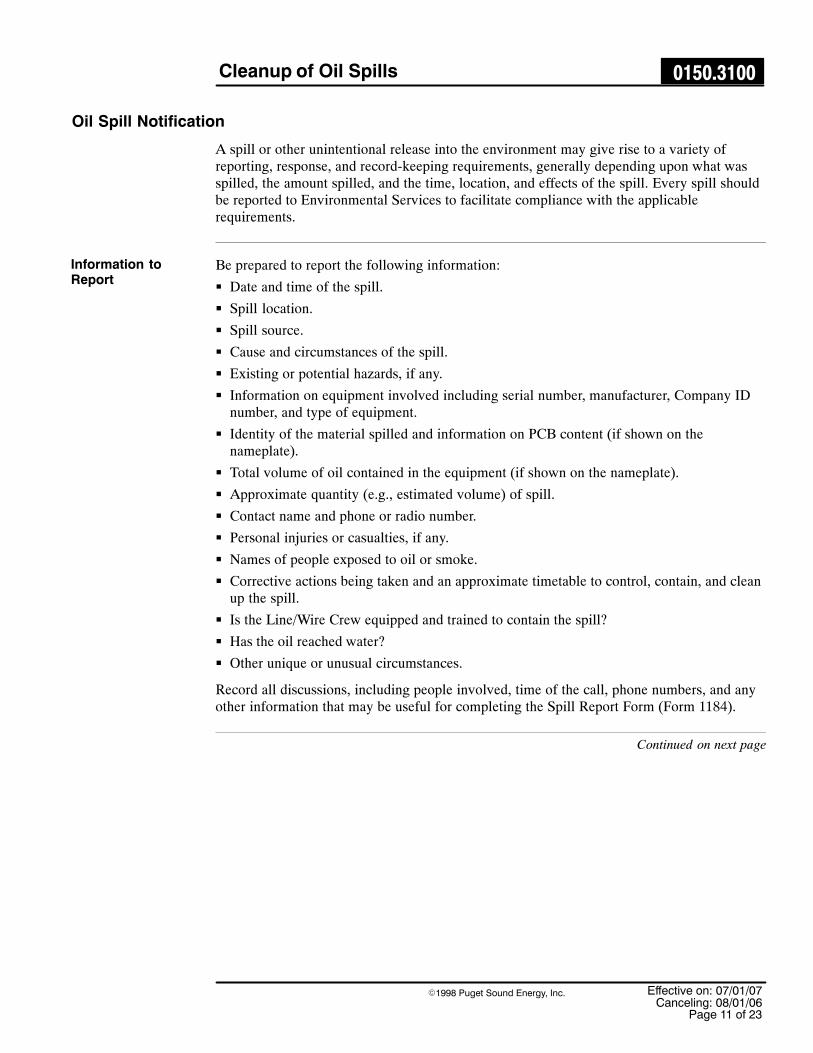
Cleanup of Oil Spills 0150.3100
Effective on: 07/01/07Canceling: 08/01/06
Page 11 of 23
�1998 Puget Sound Energy, Inc.
Oil Spill Notification
A spill or other unintentional release into the environment may give rise to a variety ofreporting, response, and record-keeping requirements, generally depending upon what wasspilled, the amount spilled, and the time, location, and effects of the spill. Every spill shouldbe reported to Environmental Services to facilitate compliance with the applicablerequirements.
Be prepared to report the following information:
� Date and time of the spill.
� Spill location.
� Spill source.
� Cause and circumstances of the spill.
� Existing or potential hazards, if any.
� Information on equipment involved including serial number, manufacturer, Company IDnumber, and type of equipment.
� Identity of the material spilled and information on PCB content (if shown on thenameplate).
� Total volume of oil contained in the equipment (if shown on the nameplate).
� Approximate quantity (e.g., estimated volume) of spill.
� Contact name and phone or radio number.
� Personal injuries or casualties, if any.
� Names of people exposed to oil or smoke.
� Corrective actions being taken and an approximate timetable to control, contain, and cleanup the spill.
� Is the Line/Wire Crew equipped and trained to contain the spill?
� Has the oil reached water?
� Other unique or unusual circumstances.
Record all discussions, including people involved, time of the call, phone numbers, and anyother information that may be useful for completing the Spill Report Form (Form 1184).
Continued on next page
Information toReport

Cleanup of Oil Spills 0150.3100
Effective on: 07/01/07Canceling: 08/01/06Page 12 of 23
�1998 Puget Sound Energy, Inc.
Oil Spill Notification, Continued
Table 7 shows the plan for ensuring that all appropriate parties are promptly notified of spillevents.
Notification of appropriate parties
Person Responsible Whom to Notify When
Crew Foreman whodiscovers the spill
Supervisor Immediately
Crew Foreman whodiscovers the spill
Submit draft Spill ReportForm (Form 1184) toSupervisor.
Within 48 hours
Crew Foreman whodiscovers the spill or fire
Environmental Services24-Hour Spill Pager (seeTable 2)
� Fax a copy of the draftSpill Report Form (Form 1184) as soon as itis available.
Immediately if spill responseassistance is needed.
Crew Foreman whodiscovers the spill or fire
Dispatcher/SystemOperations
� Fax a copy of the draftSpill Report Form (Form 1184) as soon as itis available.
Immediately
Dispatcher/SystemOperations
Environmental Services24-Hour Spill Pager (seeTable 2)
Immediately for fires and forany release to water.
As soon as possible for otherreleases.
Dispatcher/SystemOperations
If there is a fire:
� Local Fire Department
� PSE Emergency Contacts
� Risk Management
� Corporate Relations
Immediately
Environmental ServicesDepartment
Report spill event to externalregulatory agencies ifrequired or appropriate.
Immediately or withinregulatory deadlines.
Supervisor Submit completed SpillReport Form (Form 1184) toEnvironmental Services.
Within 48 hours
Continued on next page
Internal Reportingof Oil Spills
Table 7

Cleanup of Oil Spills 0150.3100
Effective on: 07/01/07Canceling: 08/01/06
Page 13 of 23
�1998 Puget Sound Energy, Inc.
Environmental Services will make all necessary notifications to appropriate regulatoryagencies when appropriate. It is imperative that the Environmental Services 24-Hour SpillPager (see Table 2) be called promptly to report every spill, so that Environmental Servicescan assess the situation, determine whether external spill reporting is required, and make theappropriate notifications within the time frames specified.
Spill Characterization
This section describes the procedure for characterizing the spilled material and the extent ofcontamination. A diagram should be drawn on the back of the white page of the Spill ReportForm (Form 1184) to show the center and extent of contamination for each visible area ofcontamination.
Environmental Services will coordinate the response and cleanup for spills containing PCBs.Each piece of electrical equipment can contain different amounts of PCBs. Spills of oil with50 ppm or greater of PCBs are subject to specific cleanup requirements.
Often the manufacturer will state the concentration of PCBs contained in the dielectric fluidon the equipment nameplate. Additionally a search by serial number (from themanufacturer’s nameplate) can be used to query PSE’s SAP database to determine if sampledata already exists for the equipment.
NOTE: Analyses for PCB concentrations that were conducted prior to 1986, yellow stickers(less than 50 ppm of PCBs), and blue stickers (non-PCB) are no longer honored. Analysesmust be performed to properly document the concentrations of PCBs in the oil.
If a spill occurs during business hours, contact Environmental Services to determine theprobable PCB concentration. If the spill occurs after normal business hours, the Dispatcher orSystem Operations should contact the Environmental Services 24-Hour Spill Pager (seeTable 2).
The spilled oil and contaminated area may need to be sampled to characterize the extent ofthe contamination. Such sampling, as well as post-cleanup sampling, is specifically requiredfor spills of oil with 50 ppm or greater of PCBs. Contact the Environmental Services24-Hour Spill Pager (see Table 2) or Environmental Services to coordinate any sampling thatmay be necessary.
External Reportingof Oil Spills
Determining PCBConcentration
If Spill OccursDuring of AfterBusiness Hours
Sampling the SpillArea
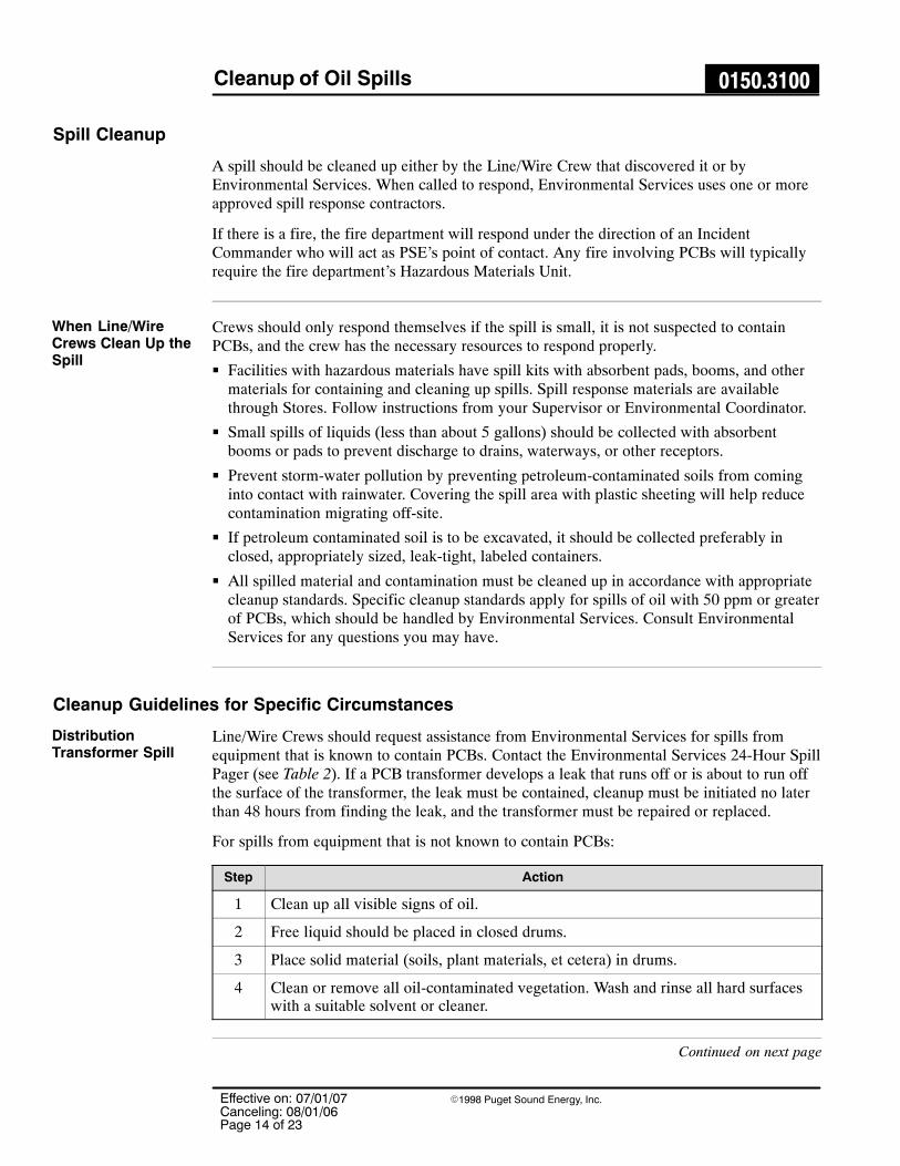
Cleanup of Oil Spills 0150.3100
Effective on: 07/01/07Canceling: 08/01/06Page 14 of 23
�1998 Puget Sound Energy, Inc.
Spill Cleanup
A spill should be cleaned up either by the Line/Wire Crew that discovered it or byEnvironmental Services. When called to respond, Environmental Services uses one or moreapproved spill response contractors.
If there is a fire, the fire department will respond under the direction of an IncidentCommander who will act as PSE’s point of contact. Any fire involving PCBs will typicallyrequire the fire department’s Hazardous Materials Unit.
Crews should only respond themselves if the spill is small, it is not suspected to containPCBs, and the crew has the necessary resources to respond properly.
� Facilities with hazardous materials have spill kits with absorbent pads, booms, and othermaterials for containing and cleaning up spills. Spill response materials are availablethrough Stores. Follow instructions from your Supervisor or Environmental Coordinator.
� Small spills of liquids (less than about 5 gallons) should be collected with absorbentbooms or pads to prevent discharge to drains, waterways, or other receptors.
� Prevent storm-water pollution by preventing petroleum-contaminated soils from cominginto contact with rainwater. Covering the spill area with plastic sheeting will help reducecontamination migrating off-site.
� If petroleum contaminated soil is to be excavated, it should be collected preferably inclosed, appropriately sized, leak-tight, labeled containers.
� All spilled material and contamination must be cleaned up in accordance with appropriatecleanup standards. Specific cleanup standards apply for spills of oil with 50 ppm or greaterof PCBs, which should be handled by Environmental Services. Consult EnvironmentalServices for any questions you may have.
Cleanup Guidelines for Specific Circumstances
Line/Wire Crews should request assistance from Environmental Services for spills fromequipment that is known to contain PCBs. Contact the Environmental Services 24-Hour SpillPager (see Table 2). If a PCB transformer develops a leak that runs off or is about to run offthe surface of the transformer, the leak must be contained, cleanup must be initiated no laterthan 48 hours from finding the leak, and the transformer must be repaired or replaced.
For spills from equipment that is not known to contain PCBs:
Step Action
1 Clean up all visible signs of oil.
2 Free liquid should be placed in closed drums.
3 Place solid material (soils, plant materials, et cetera) in drums.
4 Clean or remove all oil-contaminated vegetation. Wash and rinse all hard surfaceswith a suitable solvent or cleaner.
Continued on next page
When Line/WireCrews Clean Up theSpill
DistributionTransformer Spill

Cleanup of Oil Spills 0150.3100
Effective on: 07/01/07Canceling: 08/01/06
Page 15 of 23
�1998 Puget Sound Energy, Inc.
Step Action
1 Make sure the area is well ventilated before you start to clean.
2 Recover liquid with a granular absorbent. Sweep it into piles with a broom, andthen pick up with a shovel and dispose of material in a closed drum.
3 Wash and rinse hard surface twice, picking up the liquid with absorbent after eachstep.
If the equipment is known to contain PCBs, contact the Environmental Services 24-HourSpill Pager (see Table 2).
� Vault spills are usually contained within the vault and may not pose an immediateenvironmental risk. Contact Environmental Services for assistance and guidance.
� Assess the quantity of oil present. Is it just a sheen on the water or is there a significantamount of oil?
Step Action
1 Place absorbent pads on the surface.
2 Move the pads around and allow time for the oil to be absorbed.
3 Remove the pads and place in a plastic bag.
Step Action
1 Environmental Services should be called to respond to large spills that exceed theavailable resources of the crew.
Contact the Environmental Services 24-Hour Spill Pager (see Table 2).
2 Typically, a vactor truck is requested to pump out the vault. See the Vactor TruckWaste Accumulation, Transport, and Disposal section of this standard.
Contact the Environmental Services 24-Hour Spill Pager (see Table 2) forassistance in scheduling a vactor truck.
Continued on next page
Oil-ContaminatedAsphalt andConcrete
Spills Within aVault
To Clean Up an OilSheen
To Clean Up aLarge Amount ofOil
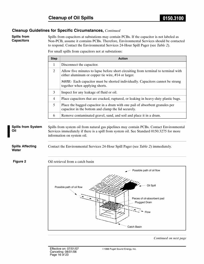
Cleanup of Oil Spills 0150.3100
Effective on: 07/01/07Canceling: 08/01/06Page 16 of 23
�1998 Puget Sound Energy, Inc.
Cleanup Guidelines for Specific Circumstances, Continued
Spills from capacitors at substations may contain PCBs. If the capacitor is not labeled asNon-PCB, assume it contains PCBs. Therefore, Environmental Services should be contactedto respond. Contact the Environmental Services 24-Hour Spill Pager (see Table 2).
For small spills from capacitors not at substations:
Step Action
1 Disconnect the capacitor.
2 Allow five minutes to lapse before short circuiting from terminal to terminal witheither aluminum or copper tie wire, #14 or larger.
NOTE: Each capacitor must be shorted individually. Capacitors cannot be strungtogether when applying shorts.
3 Inspect for any leakage of fluid or oil.
4 Place capacitors that are cracked, ruptured, or leaking in heavy-duty plastic bags.
5 Place the bagged capacitor in a drum with one pail of absorbent granules percapacitor in the bottom and clamp the lid securely.
6 Remove contaminated gravel, sand, and soil and place it in a drum.
Spills from system oil from natural gas pipelines may contain PCBs. Contact EnvironmentalServices immediately if there is a spill from system oil. See Standard 0150.3275 for moreinformation on system oil.
Contact the Environmental Services 24-Hour Spill Pager (see Table 2) immediately.
Oil retrieval from a catch basin
Possible path of oil flowOil Spill
Pieces of oil-absorbent pad
Plugged Drain
Catch Basin
Flow
Possible path of oil flow
Continued on next page
Spills fromCapacitors
Spills from SystemOil
Spills AffectingWater
Figure 2

Cleanup of Oil Spills 0150.3100
Effective on: 07/01/07Canceling: 08/01/06
Page 17 of 23
�1998 Puget Sound Energy, Inc.
Figure 3 shows containment for a large spill into a stream. The boom is used to trap oil onthe surface of the water and prevent it from flowing downstream. It is laid on the surface ofthe water and anchored at each end with a wood stake or rocks.
Large volume of oil in a stream
Boom
Flow
Boom
20� oil-absorbentbooms tied together
If a boom is not available, wire mesh may be used to build a net across a drainage ditch.Wood stakes are used to anchor the mesh in place. The absorbent material is placed on thesurface of the water on the upstream side of the mesh.
Using wire mesh as a boom
ÎÎÎÎÎÎÎÎÎÎÎÎÎÎÎÎ
Flow
Oil-absorbentMaterial
Wire Mesh Sheet
ÅÅÅÅÅÅÅÅÅÅÅÅÅÅ
Continued on next page
Large Spill
Figure 3
Use Wire Mesh
Figure 4

Cleanup of Oil Spills 0150.3100
Effective on: 07/01/07Canceling: 08/01/06Page 18 of 23
�1998 Puget Sound Energy, Inc.
Cleanup Guidelines for Specific Circumstances, Continued
One end of the boom should be anchored farther downstream than the other, forming a “V”close to the downstream end. The oil-absorbent materials or the contents of a boom are thenused to collect and remove the oil from the surface of the water. Using three or more boomsor dams is recommended.
Small volume of oil spillage
Flow
Oil-absorbent Boom
Anchor each end of boom
Impounded Oil
It is important to keep the oil from seeping into the ground. Polyethylene sheeting is used toline a trench or hole that has been dug for the purpose of collecting spilled oil.
Dam containment system
Oil trapped within
SandRock
Bentonite Base
Dig hole for oil removal
Line hole with polyethylene sheeting
Use rocks to anchor sheeting
Yard Surface
Bail oil into drums or pump into trucks
Continued on next page
Small Spill
Figure 5
Use PlasticSheeting
Figure 6

Cleanup of Oil Spills 0150.3100
Effective on: 07/01/07Canceling: 08/01/06
Page 19 of 23
�1998 Puget Sound Energy, Inc.
Figure 7 shows how a hole can be dug and lined to hold spilled oil until it can be removed.
Hole lined for oil containment
Rock Sand
Dig hole outside of bermed area for oil removal
Line hole with polyethylene sheeting
Yard Coarse
Bail oil into drum or pump into tank trucks
Figure 8 shows how rock is used to secure the lining.
Lining secured with rocks
Base Coarse
Trapped Oil
Dig hole for oil removal
Line hole with polyethylene sheeting
Use rocks to anchor sheeting
Yard Coarse
Bail oil into drum or pump into tank truckBentonite Base
If oil has spilled into a drainage ditch, a dam with a through-pipe connection may be used tocontain the oil spill, but permit water to pass.
Dam with a through-pipe
Drainage Ditch
See DamSection
StationDrainageOutlet
Flow
DAM SECTION
Drain Pipe
Earth Dam
Flow
Dig a Hole
Figure 7
Use a Rock
Figure 8
Dam withThrough-Pipe
Figure 9
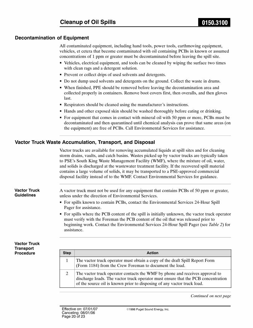
Cleanup of Oil Spills 0150.3100
Effective on: 07/01/07Canceling: 08/01/06Page 20 of 23
�1998 Puget Sound Energy, Inc.
Decontamination of Equipment
All contaminated equipment, including hand tools, power tools, earthmoving equipment,vehicles, et cetera that become contaminated with oil containing PCBs in known or assumedconcentrations of 1 ppm or greater must be decontaminated before leaving the spill site.
� Vehicles, electrical equipment, and tools can be cleaned by wiping the surface two timeswith clean rags and a detergent solution.
� Prevent or collect drips of used solvents and detergents.
� Do not dump used solvents and detergents on the ground. Collect the waste in drums.
� When finished, PPE should be removed before leaving the decontamination area andcollected properly in containers. Remove boot covers first, then overalls, and then gloveslast.
� Respirators should be cleaned using the manufacturer’s instructions.
� Hands and other exposed skin should be washed thoroughly before eating or drinking.
� For equipment that comes in contact with mineral oil with 50 ppm or more, PCBs must bedecontaminated and then quarantined until chemical analysis can prove that same areas (onthe equipment) are free of PCBs. Call Environmental Services for assistance.
Vactor Truck Waste Accumulation, Transport, and Disposal
Vactor trucks are available for removing accumulated liquids at spill sites and for cleaningstorm drains, vaults, and catch basins. Wastes picked up by vactor trucks are typically takento PSE’s South King Waste Management Facility (WMF), where the mixture of oil, water,and solids is discharged at the wastewater treatment facility. If the recovered spill materialcontains a large volume of solids, it may be transported to a PSE-approved commercialdisposal facility instead of to the WMF. Contact Environmental Services for guidance.
A vactor truck must not be used for any equipment that contains PCBs of 50 ppm or greater,unless under the direction of Environmental Services.
� For spills known to contain PCBs, contact the Environmental Services 24-Hour SpillPager for assistance.
� For spills where the PCB content of the spill is initially unknown, the vactor truck operatormust verify with the Foreman the PCB content of the oil that was released prior tobeginning work. Contact the Environmental Services 24-Hour Spill Pager (see Table 2) forassistance.
Step Action
1 The vactor truck operator must obtain a copy of the draft Spill Report Form (Form 1184) from the Crew Foreman to document the load.
2 The vactor truck operator contacts the WMF by phone and receives approval todischarge loads. The vactor truck operator must ensure that the PCB concentrationof the source oil is known prior to disposing of any vactor truck load.
Continued on next page
Vactor TruckGuidelines
Vactor TruckTransportProcedure

Cleanup of Oil Spills 0150.3100
Effective on: 07/01/07Canceling: 08/01/06
Page 21 of 23
�1998 Puget Sound Energy, Inc.
Step Action
3 The vactor truck operator transports the load to the WMF where it is discharged incompliance with discharge requirements set forth in the WMF Operations andMaintenance Manual.
4 The vactor truck operator logs the required information in the vactor truck logbook.
5 The vactor truck operator provides a copy of the Spill Report Form (Form 1184) toWMF personnel.
6 The WMF personnel process the discharged load in accordance with the WMFOperations and Maintenance Manual.
If the spill volume is small, materials collected from the spill should be placed in drums andtransported to the nearest Service Center. Refer to Standard 0150.3125 for guidance.
Record Keeping
This section sets forth the records required when a cleanup of an oil spill has been performed.
If there is an injury or illness, the Supervisor shall complete an Industrial Injury & IllnessReport (Form 3892) and submit it to the Safety Department.
The Crew Foreman should prepare a draft Spill Report Form (Form 1184) and submit it tothe Supervisor, who finalizes the report and submits it to Environmental Services. IfEnvironmental Services responds to the spill, they will complete their own Spill ReportForm (Form 1184).
� The white copy of the spill report is submitted to Environmental Services at the SouthKing Waste Management Facility.
� The canary copy is included with any samples sent to a laboratory.
� The pink copy is maintained at the satellite Service Center in the on-site files.
� The goldenrod copy should stay with the spill waste (taken by the vactor truck driver orkept with the containers of spill waste).
Spill reports need to include the information on the status of corrective actions and any plansfor follow-up should be described in detail.
Continued on next page
Spill Waste andEquipmentAccumulation andTransport
Industrial Injury &Illness Report(Form 3892)
Spill Report Form(Form 1184)

Cleanup of Oil Spills 0150.3100
Effective on: 07/01/07Canceling: 08/01/06Page 22 of 23
�1998 Puget Sound Energy, Inc.
Record Keeping, Continued
For cleanups of spills of oil with 50 ppm or greater of PCBs, records of decontaminationmust be maintained for five years, including:
� Identification of the source of the spill (e.g., type of equipment).
� Estimated or actual date and time of the spill occurrence.
� The date and time cleanup was completed or terminated. If cleanup was delayed byemergency or adverse weather, include the nature and duration of the delay.
� A brief description of the spill location and the nature of the materials contaminated.
� Precleanup sampling data used to establish the spill boundaries, if required, because ofinsufficient visible traces and a brief description of the sampling methodology used toestablish the spill boundaries.
� A brief description of the solid surfaces cleaned.
� Approximate depth of soil excavation and the amount of soil removed.
� A signed certification statement stating that the cleanup requirements have been met andthat the information contained in the record is true.
� For spills in nonrestricted access areas, post cleanup verification sampling data, and if nototherwise apparent from the documentation, a brief description of the samplingmethodology and analytical techniques used.
� Analytical results of samples obtained from oil-filled equipment are entered into the SAPdatabase. A hard copy is maintained in the Environmental Services files at the WasteManagement Facility.
� Analytical results of samples obtained to characterize soil conditions in the spill area arefiled with the Spill Report Form (Form 1184).
� Analytical results of samples obtained to characterize waste are filed with other wasterecords (profiles, manifests, et cetera).
Record keeping to track the equipment includes:
� For equipment that is less than 50 ppm of PCBs � the analytical report from SAPshowing the equipment’s PCB concentration and a shipping record.
� For PCB capacitors and equipment that is 50 ppm or greater of PCBs � the analyticalreport from SAP showing the equipment’s PCB concentration and a WMF ShippingDocument (Form 1754), which acts as an internal shipping manifest.
� Record keeping to track spill waste shipments including bills of lading.
� Hazardous/TSCA waste manifests
� Certificates of disposal for shipments of PCB wastes
DecontaminationRecordsMaintenance forSpills withConcentrations of50 ppm or Greaterof PCBs
Analytical Results
Shipping Records
Cleanup of Oil Spills 0150.3100
Effective on: 07/01/07Canceling: 08/01/06
Page 23 of 23
�1998 Puget Sound Energy, Inc.
References
The following Puget Sound Energy documents apply to this standard.
0150.3125 Temporary Storage of PCB Items0150.3275 Collecting, Managing, and Disposing of Liquids from Natural Gas
Equipment
1184 Spill Report Form1257 Chain of Custody Report1754 WMF Shipping Document3892 Industrial Injury & Illness Report
Employee Safety & Health Program
Sources
112 Oil Pollution Prevention761 Polychlorinated biphenyls (PCBs) Manufacturing, Processing, Distribution
in Commerce, and Use Prohibitions
Forms
40 CFR

Oil Sampling Procedures for DistributionTransformers and Oil-Filled Equipment 0150.3150
Effective on: 07/01/07Canceling: 08/01/06
Page 1 of 15
�1998 Puget Sound Energy, Inc.
This standard covers oil sampling procedures for distribution transformers and oil-filledequipment. For substation equipment, see Standard 8625.1070.
Background
Sampling of equipment is sometimes required to determine the PCB concentration of oil toprofile a waste or to satisfy a customer’s request, for example, during an environmental siteassessment or property transfer. All sampling should be done by Environmental Servicespersonnel. When that is not possible, the Environmental Services Department should becalled for guidance.
In This Standard
These topics are covered in this standard:
Topic See Page
Do Not Test for PCBs 2
Responsibilities 2
Safety 3
Personal Protective Equipment 3
First Aid 4
Tools, Materials, and Equipment 5
Ways to Take an Oil Sample 6
Sampling Methods 7
Impalement Method 8
Pressure Relief Valve Method 10
Bay-O-Net Method 11
Valve Method 12
Cleanup 14
Decontamination of Nondisposable Equipment 14
Shipping the Sample 15
Shipping DGA Analysis 15
Record Keeping 15
These procedures comply with the Environmental Protection Agency and the OSHAand NIOSH guidelines that protect the environment and health of Puget SoundEnergy workers. Federal regulations require a yearly review of this practice.
Scope
WARNING!
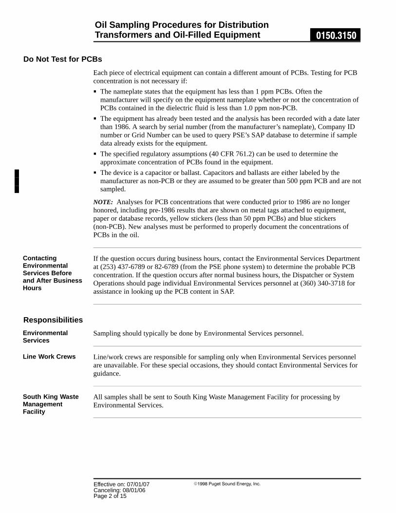
Oil Sampling Procedures for DistributionTransformers and Oil-Filled Equipment 0150.3150
Effective on: 07/01/07Canceling: 08/01/06Page 2 of 15
�1998 Puget Sound Energy, Inc.
Do Not Test for PCBs
Each piece of electrical equipment can contain a different amount of PCBs. Testing for PCBconcentration is not necessary if:
� The nameplate states that the equipment has less than 1 ppm PCBs. Often themanufacturer will specify on the equipment nameplate whether or not the concentration ofPCBs contained in the dielectric fluid is less than 1.0 ppm non-PCB.
� The equipment has already been tested and the analysis has been recorded with a date laterthan 1986. A search by serial number (from the manufacturer’s nameplate), Company IDnumber or Grid Number can be used to query PSE’s SAP database to determine if sampledata already exists for the equipment.
� The specified regulatory assumptions (40 CFR 761.2) can be used to determine theapproximate concentration of PCBs found in the equipment.
� The device is a capacitor or ballast. Capacitors and ballasts are either labeled by themanufacturer as non-PCB or they are assumed to be greater than 500 ppm PCB and are notsampled.
NOTE: Analyses for PCB concentrations that were conducted prior to 1986 are no longerhonored, including pre-1986 results that are shown on metal tags attached to equipment,paper or database records, yellow stickers (less than 50 ppm PCBs) and blue stickers(non-PCB). New analyses must be performed to properly document the concentrations ofPCBs in the oil.
If the question occurs during business hours, contact the Environmental Services Departmentat (253) 437-6789 or 82-6789 (from the PSE phone system) to determine the probable PCBconcentration. If the question occurs after normal business hours, the Dispatcher or SystemOperations should page individual Environmental Services personnel at (360) 340-3718 forassistance in looking up the PCB content in SAP.
Responsibilities
Sampling should typically be done by Environmental Services personnel.
Line/work crews are responsible for sampling only when Environmental Services personnelare unavailable. For these special occasions, they should contact Environmental Services forguidance.
All samples shall be sent to South King Waste Management Facility for processing byEnvironmental Services.
ContactingEnvironmentalServices Beforeand After BusinessHours
EnvironmentalServices
Line Work Crews
South King WasteManagementFacility

Oil Sampling Procedures for DistributionTransformers and Oil-Filled Equipment 0150.3150
Effective on: 07/01/07Canceling: 08/01/06
Page 3 of 15
�1998 Puget Sound Energy, Inc.
SafetyOil sampling performed on energized systems shall be done only with hotstick tools designedespecially for the job.
Oil sampling procedure for energized systems shall not be performed on cast iron orfiberglass transformers.
If you choose to take an oil sample while the transformer is energized, use insulatedtools.
Employees and conducting objects shall not come within the minimum distances ofenergized lines or conductors according to Table 1 in WAC 296-45-325.
Waste material and oil must be placed in the Service Center’s designated PCB holding area.Check with the Storekeeper to make sure you place the waste appropriately.
Personal Protective EquipmentPersonal protective equipment is to be worn during all phases of oil sampling.
Disposable plastic gloves and a face shield, and, when necessary, disposable coveralls andboots shall be worn whenever you take oil samples.
When solvents are used in a confined area, or when air quality is questionable, use arespirator.
This chart illustrates the kind of personal protective equipment you should wear during theoil sampling process.
PersonalProtectiveEquipment Type MID
Examples ofAppropriate Use
Eye Protection Safety glasseswith side shields
Goggles
68270006827101
6827300
Collecting oil samples for gaschromatograph analyses.
Eye Protection Goggles
Face shield
6827300
6829000non-hard hat
6830000hat-mounted
6888000
Any time splash could occur.
Gloves Nitrile − protectup to 1 hour
6858000 Gloves are required for handcontact with PCBs: Oils,leaking/contaminatedequipment, soil, surfaces.
A complete list of personal protective clothing and equipment is in Standard 0150.3100.
DANGER!
WAC Rule
PCB Holding Area
For Oil Sampling

Oil Sampling Procedures for DistributionTransformers and Oil-Filled Equipment 0150.3150
Effective on: 07/01/07Canceling: 08/01/06Page 4 of 15
�1998 Puget Sound Energy, Inc.
First AidIf eyes, skin, or clothing come in contact with PCBs, or if they are ingested or inhaled,follow these abbreviated first aid treatments. More complete treatments are in Standard 0150.3100.
Flush eyes with water or eye irrigation solution for at least 15 minutes.
Clean skin immediately with soap and water. If soap and water aren’t available, use waterlesshand cleaner.
Remove contaminated clothing as soon as possible.
Employee is to be taken to a hospital immediately.
If nausea, breathing difficulty or dizziness occur, employee is to be taken to a hospitalimmediately.
Eye Contact
Skin Contact
Clothing Contact
Ingesting
Inhaling

Oil Sampling Procedures for DistributionTransformers and Oil-Filled Equipment 0150.3150
Effective on: 07/01/07Canceling: 08/01/06
Page 5 of 15
�1998 Puget Sound Energy, Inc.
Tools, Materials, and Equipment
These tools and materials are required for oil sampling operations.
Labels/Forms MID Used for
Transformer InspectionForm
None All oil sampling methods
EPA yellow PCB Mark MLlabel
3849100 Containers greater than 50ppm or transformers 500 orgreater ppm
Chain of Custody ReportDissolved Gas Analysis
F483.65 (printing form) Shipping the DGA sample
Chain of Custody ReportPCB/TPH Analysis
F483.55 (printing form) Shipping the sample
Chain of Custody ReportEmergency Analysis
F483.50 (printing form) Shipping the sample for arush analysis
Tools MID Used for
Hammer 7355100 Impalement method
Battery Operated DrillMotor, 3/8� Drive, SlowSpeed
None Impalement method
Drill Bit, Split Fluted 9/32�w/ Magnetized Collet, 1/16�Depth, OH
7222002 Impalement method
5/16� Socket, 3/8� Drive None − Available fromJACO Construction Co.
Impalement method
Insulated Tools MID Used for
Hotstick equipped withdisposable syringe and hoseapplicator
None − Available fromJACO Construction Co.
Any energized oil sampling
Hotstick modified for drilland drill bit
None − Available fromJACO Construction Co.
Any energized oil sampling
Shotgun 7351100 Any energized oil sampling
Continued on next page
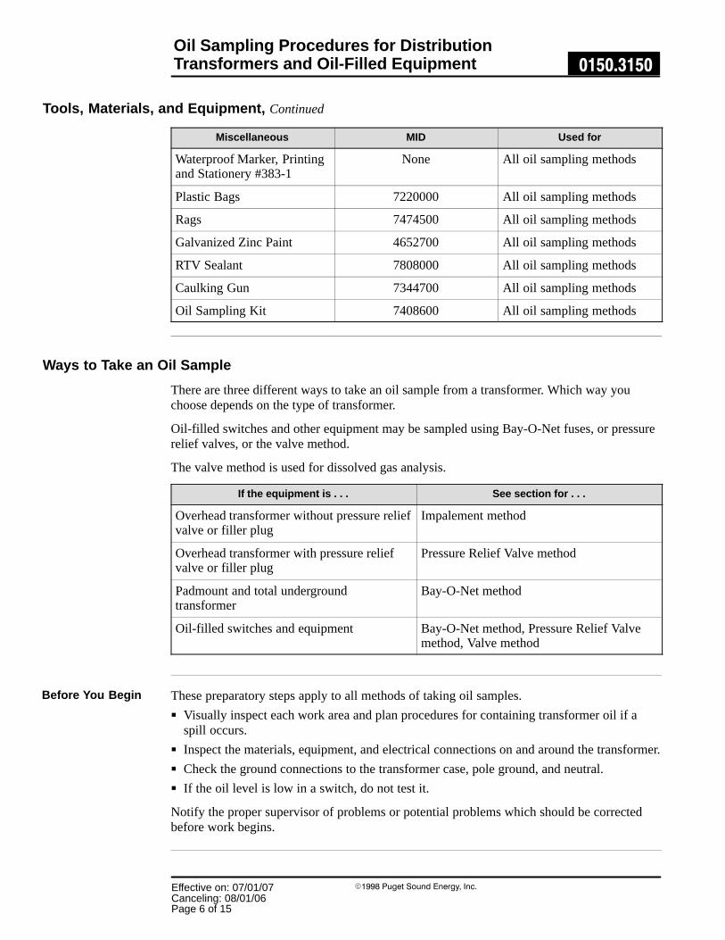
Oil Sampling Procedures for DistributionTransformers and Oil-Filled Equipment 0150.3150
Effective on: 07/01/07Canceling: 08/01/06Page 6 of 15
�1998 Puget Sound Energy, Inc.
Tools, Materials, and Equipment, Continued
Miscellaneous MID Used for
Waterproof Marker, Printingand Stationery #383-1
None All oil sampling methods
Plastic Bags 7220000 All oil sampling methods
Rags 7474500 All oil sampling methods
Galvanized Zinc Paint 4652700 All oil sampling methods
RTV Sealant 7808000 All oil sampling methods
Caulking Gun 7344700 All oil sampling methods
Oil Sampling Kit 7408600 All oil sampling methods
Ways to Take an Oil Sample
There are three different ways to take an oil sample from a transformer. Which way youchoose depends on the type of transformer.
Oil-filled switches and other equipment may be sampled using Bay-O-Net fuses, or pressurerelief valves, or the valve method.
The valve method is used for dissolved gas analysis.
If the equipment is . . . See section for . . .
Overhead transformer without pressure reliefvalve or filler plug
Impalement method
Overhead transformer with pressure reliefvalve or filler plug
Pressure Relief Valve method
Padmount and total undergroundtransformer
Bay-O-Net method
Oil-filled switches and equipment Bay-O-Net method, Pressure Relief Valvemethod, Valve method
These preparatory steps apply to all methods of taking oil samples.
� Visually inspect each work area and plan procedures for containing transformer oil if aspill occurs.
� Inspect the materials, equipment, and electrical connections on and around the transformer.
� Check the ground connections to the transformer case, pole ground, and neutral.
� If the oil level is low in a switch, do not test it.
Notify the proper supervisor of problems or potential problems which should be correctedbefore work begins.
Before You Begin

Oil Sampling Procedures for DistributionTransformers and Oil-Filled Equipment 0150.3150
Effective on: 07/01/07Canceling: 08/01/06
Page 7 of 15
�1998 Puget Sound Energy, Inc.
Sampling Methods
These are the procedures for the four methods to take oil samples from a distributiontransformer:
� Impalement
� Pressure relief valve
� Bay-O-Net
� Valve
If you choose to take an oil sample while the transformer is energized, use insulatedtools.
Oil sampling areas
Oil FillPressure
Relief
Oil Line
Bay-O-Net
If pressure relief valve or oil fillplug is not available, drill oil
sample hole 1� below cover.
DANGER!
Figure 1

Oil Sampling Procedures for DistributionTransformers and Oil-Filled Equipment 0150.3150
Effective on: 07/01/07Canceling: 08/01/06Page 8 of 15
�1998 Puget Sound Energy, Inc.
Impalement Method
This section tells you how to use the impalement method to take oil samples from overheadtransformers without pressure relief valves or filler plugs.
Impalement method
Pressure VentPlug Or Valve
Lifting Lug
Steel-dipped DriveRivet 1� Below Lid
Service CenterSample Label
Continued on next page
Figure 2

Oil Sampling Procedures for DistributionTransformers and Oil-Filled Equipment 0150.3150
Effective on: 07/01/07Canceling: 08/01/06
Page 9 of 15
�1998 Puget Sound Energy, Inc.
Select a location for the oil sample hole above the oil line.
Step Action Procedure
1 Select, mark, and cleanoil sampling location.
Measure 1/2 inch to 1 inch below the cover or top,between the secondary neutral bushing and the liftinglug, and mark the location.
Use denatured alcohol to remove dirt andcontamination from the location.
2 Drill the oil samplinghole.
Use a slow-speed drill with a split fluted bit to slowlydrill the transformer case at the marked location untilthe collet touches the case.
The collet will act as a stop, keeping the drill fromgoing all the way through.
NOTE: Drill shavings caught inside the magnetizedcollet should be cleaned out frequently with a smallwire.
3 Drive the punch throughthe case.
Use an impalement tool and a hammer to drive thepunch through the wall of the transformer case untilthe collar touches the case.
These next steps tell you how to draw the sample, clear the tube, and clean the area. Select alocation for the oil sample hole above the oil line.
Step Action Procedure
1 Draw oil sample. Use a disposable syringe to insert the hose into thehole and draw out the oil sample.
NOTE: The syringe plunger should be completely inbefore drawing out the sample.
2 Clear tubing of air. Tip the syringe plunger end down so the air is towardthe tubing end of the syringe, then move the plungerforward until most of the air is out of the syringe.
3 Wipe the area. Use denatured alcohol to wipe the drilling area cleanof any oily residue.
Continued on next page
Select Oil SamplingPoint
Drawing the OilSample

Oil Sampling Procedures for DistributionTransformers and Oil-Filled Equipment 0150.3150
Effective on: 07/01/07Canceling: 08/01/06Page 10 of 15
�1998 Puget Sound Energy, Inc.
Impalement Method, Continued
The next steps tell you how to plug and seal the hole.
Step Action Procedure
1 Plug the hole. Place a dipped steel rivet into sampling hole andstrike the drive pin with a hammer.
2 Seal the hole. Apply RTV sealant around the drive rivet. Be carefulto completely cover the rivet and any surroundingarea where paint may have been chipped off.
3 Check for leaks. Check for leaks around the newly installed rivet.
See the Cleanup and Applying Labels section in this standard to finish operation.
Pressure Relief Valve Method
This section tells you how to use the pressure relief valves or filler plugs to take an oilsample.
Use this method for overhead transformers with pressure relief valves or filler plugs.
Step Action Procedure
1 Clean the area. Use denatured alcohol to remove dirt andcontamination from the location.
2 Remove valve. Remove the valve or plug from the transformer case
3 Draw oil sample. Use a disposable syringe to insert the hose into thehole and draw out the oil sample.
NOTE: The syringe plunger should be completely inbefore drawing out the sample.
4 Clean the area. Use denatured alcohol to wipe the drilling area cleanof any oily residue.
5 Replace valve. Replace the valve or plug and check for leaks.
See the Cleanup and Applying Labels section of t his standard to finish operation.
Finishing theOperation
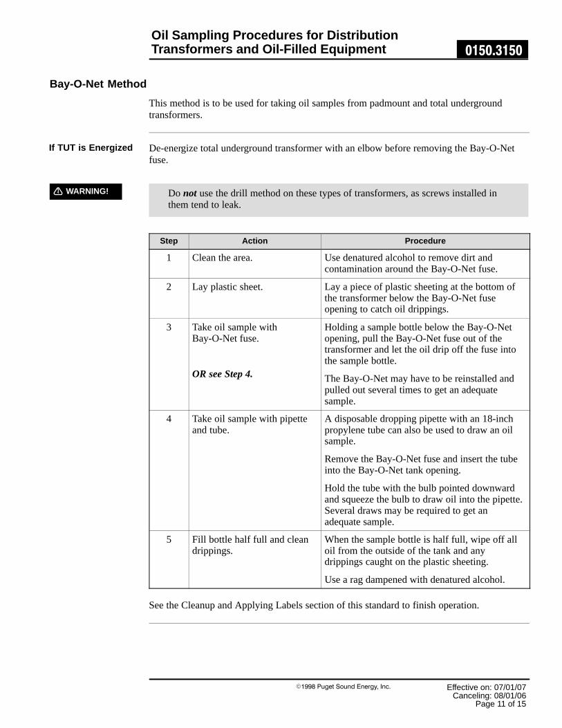
Oil Sampling Procedures for DistributionTransformers and Oil-Filled Equipment 0150.3150
Effective on: 07/01/07Canceling: 08/01/06
Page 11 of 15
�1998 Puget Sound Energy, Inc.
Bay-O-Net Method
This method is to be used for taking oil samples from padmount and total undergroundtransformers.
De-energize total underground transformer with an elbow before removing the Bay-O-Netfuse.
Do not use the drill method on these types of transformers, as screws installed inthem tend to leak.
Step Action Procedure
1 Clean the area. Use denatured alcohol to remove dirt andcontamination around the Bay-O-Net fuse.
2 Lay plastic sheet. Lay a piece of plastic sheeting at the bottom ofthe transformer below the Bay-O-Net fuseopening to catch oil drippings.
3 Take oil sample withBay-O-Net fuse.
OR see Step 4.
Holding a sample bottle below the Bay-O-Netopening, pull the Bay-O-Net fuse out of thetransformer and let the oil drip off the fuse intothe sample bottle.
The Bay-O-Net may have to be reinstalled andpulled out several times to get an adequatesample.
4 Take oil sample with pipetteand tube.
A disposable dropping pipette with an 18-inchpropylene tube can also be used to draw an oilsample.
Remove the Bay-O-Net fuse and insert the tubeinto the Bay-O-Net tank opening.
Hold the tube with the bulb pointed downwardand squeeze the bulb to draw oil into the pipette.Several draws may be required to get anadequate sample.
5 Fill bottle half full and cleandrippings.
When the sample bottle is half full, wipe off alloil from the outside of the tank and anydrippings caught on the plastic sheeting.
Use a rag dampened with denatured alcohol.
See the Cleanup and Applying Labels section of this standard to finish operation.
If TUT is Energized
WARNING!

Oil Sampling Procedures for DistributionTransformers and Oil-Filled Equipment 0150.3150
Effective on: 07/01/07Canceling: 08/01/06Page 12 of 15
�1998 Puget Sound Energy, Inc.
Valve MethodThis method is to be used for taking oil samples from padmount oil-filled switches andequipment.
These first steps tell you how to prepare the area.
Step Action Procedure
1 Clean the area. Use denatured alcohol to remove dirt andcontamination around the valve.
2 Remove the switch valveplug.
Slightly open the valve to flush out any stagnantoil.
3 Attach bushing adapter. If a sampling cock is already installed, use thatinstead.
4 Attach brass connector toadapter.
Check for tightness.
5 Allow one gallon of oil toflow into waste oil container.
This ensures the sample will be obtained fromthe main section switch.
If air bubbles, sludge, or sediment are in this oil,continue flushing until you see a steady flow ofclear oil.
6 Close the drain valve. − − −
Valve method − dissolved gas analysis
Plastic hose towaste-oil container
Hold Cylinder Vertically
Plastic hose to switchsampling valve
Switch
Continued on next page
Prepare the Area
Figure 3

Oil Sampling Procedures for DistributionTransformers and Oil-Filled Equipment 0150.3150
Effective on: 07/01/07Canceling: 08/01/06
Page 13 of 15
�1998 Puget Sound Energy, Inc.
These steps tell you how to attach the sample fittings.
Step Action Procedure
1 Connect sample cylinder tolarge plastic tube.
Use the serrated brass fitting.
2 Connect small plastic tube tothe other end of the cylinder.
Use the Luer-Lok fitting.
3 Hold the cylinder verticallywith the large plastic tube onthe bottom.
A. Open the valve at the switch.
B. Open the bottom cylinder valve.
C. Open the upper cylinder valve.
These steps tell you how to take the oil sample and replace the plug.
Step Action Procedure
1 Allow one quart to flow intothe waste oil container.
If air bubbles are seen in the plastic tube, tap orshake the tube lightly. Flush with oil until theflow out of the cylinder is free of bubbles.
2 Close the cylinder. A. Close the upper cylinder valve.
B. Close the bottom cylinder valve.
C. Close the switch valve.
3 Disconnect the plastic tubes. Check the cylinder for air bubbles by shaking itand listening for oil movement. If there is theremovement, reconnect the cylinder and flushmore oil through until the cylinder is completelyfilled.
4 Remove bushing adapter andreplace plug.
See the Cleanup and Applying Labels section of this standard to finish operation.
Attach SampleFittings
Take the OilSample

Oil Sampling Procedures for DistributionTransformers and Oil-Filled Equipment 0150.3150
Effective on: 07/01/07Canceling: 08/01/06Page 14 of 15
�1998 Puget Sound Energy, Inc.
Cleanup
Cleanup after you take the oil sample is the same for all methods.
Step Action
1 Clean up all visible signs of oil.
2 Place rags and other material used to clean up oil in a plastic bag. Dispose of it inthe designated PCB holding area located at the Service Center.
3 Tools shall be cleaned with alcohol.
Decontamination of Nondisposable Equipment
Nondisposable equipment means hand tools, power tools, earthmoving equipment, vehicles,et cetera that become contaminated with oil containing PCBs in known or assumedconcentrations of 1 ppm or greater.
All contaminated equipment, including vehicles, should be decontaminated before leavingthe spill site.
Equipment Procedure
Vehicles Wipe two times with clean rags and a detergent solution.
Electrical equipment and tools Wipe two times with clean rags and a solvent.
� Prevent or collect drips of used solvents and detergents.
� Do not dump used solvents and detergents on the ground.
� Place used solvents and detergents in properly labeled drums and send to General Storesfor appropriate disposal.
Personal protective equipment should be removed before leaving the decontamination areaand disposed of properly in containers.
� Respirators should be cleaned using the manufacturer’s instructions.
� Hands and other exposed skin should be washed thoroughly before eating or drinking.
Remove personal protective equipment in this order:
� Boot covers
� Overalls
� Gloves
Solvents andDetergents
Personal ProtectiveEquipment

Oil Sampling Procedures for DistributionTransformers and Oil-Filled Equipment 0150.3150
Effective on: 07/01/07Canceling: 08/01/06
Page 15 of 15
�1998 Puget Sound Energy, Inc.
Shipping the Sample
Ship samples for PCB analysis to the South King Waste Management Facility, SKC-WMF.
� Styrofoam mailers, each of which holds 20 samples, are available from EnvironmentalServices for this purpose.
� If a Styrofoam mailer is not available, wrap the sample vials in absorbent pads to cushionthem and place them in a cardboard box.
Shipping DGA Analysis
All Dissolved Gas Analysis is sent directly to Doble in Massachusetts.
Record Keeping
Analytical results of samples obtained from oil-filled equipment are entered into the SAPdatabase. A hard copy is maintained in the Environmental Services Department files at theWaste Management Facility.
References
The following Puget Sound Energy documents apply to this standard:
0150.3100 Cleanup of Oil Spills8625.1070 Oil-Sampling Procedures for Oil-Filled Substation Equipment
Sources
Part 112 Oil Pollution PreventionPart 761 Polychlorinated Biphenyls (PCBs) Manufacturing, Processing, Distribution
in Commerce, and Use Prohibitions
296-45-325 Working on or Near Energized Parts
40 CFR
WAC

A placard with the following wording shall be attached to locked drainage valves for containment areas.
NOTE
THIS CONTAINMENT DRAIN VALVE NORMALLY LOCKED IN THE CLOSED POSITION
DRAINING PROCEDURE:
1. Check Diked Containment Area for presence of oil.
2. If no oil is detected, unlock and open valve.
3. Close valve and lock when draining is completed.
4. If oil is detected in the Diked Containment Area, refer to the Spill Prevention, Control, and Countermeasure Plan (SPCC Plan) for response procedures and notifications. DO NOT open valve.

APPENDIX C MAINTENANCE AND INSPECTION RECORDS