Embed Size (px)
Citation preview
Spirometer Operation Manual (Ver. 1.0) 1/42
SPIROMETER OPERATION MANUAL
(Ver.1.0)
Spirometer Operation Manual
Spirometer Operation Manual (Ver. 1.0) 2/42
Terms of Warranty
- This product is manufactured and passed through strict quality control and
thorough inspection. Compensation standard concerning repair,
replacement, refund of the product complies with “Consumer’s protection
law” noticed by Ministry of Finance and Economy.
- EKG 3000S is warranted by Bionet Co.,Ltd to be free from defects in
material and workmanship for one year from date of purchase.
- Warranty repair or replacement will be made by Bionet Service Center at
no charge for warranty period if properly used under normal condition in
accordance with the instructions for use.
- In the event of a malfunction or failure during warranty period, customer
should inform Bionet Co.,Ltd of the model name, serial number, date of
purchase and explanation of failure of the defective equipment.
Spirometer Operation Manual
Spirometer Operation Manual (Ver. 1.0) 3/42
How to reach us …
Service calls Following are telephone numbers and addresses for ro contacting various service, product supplies and sales s personnel.
To open a Service call with Bionet Co.,Ltd, contact the numbers listed below.
Product and Purchase Inquiry
Service Center
Bionet Co.,Ltd - Tel : +82-2-6300-6418
Fax : +82-2-6499-7789
※ In the event of a malfunction or failure , contact
Service Dept. of Bionet Co.,Ltd along with the model name, serial number, date of purchase and explanation of failure.
Supply products and Order accessories
Contact Bionet Co.,Ltd or Sales agency for supplying products and ordering other accessories.
Tel : +82-2-6300-6418
Technical
Support
For any technical questions or problems on the equipment, call ;
Tel : +82-2-6300-6419
Spirometer Operation Manual
Spirometer Operation Manual (Ver. 1.0) 4/42
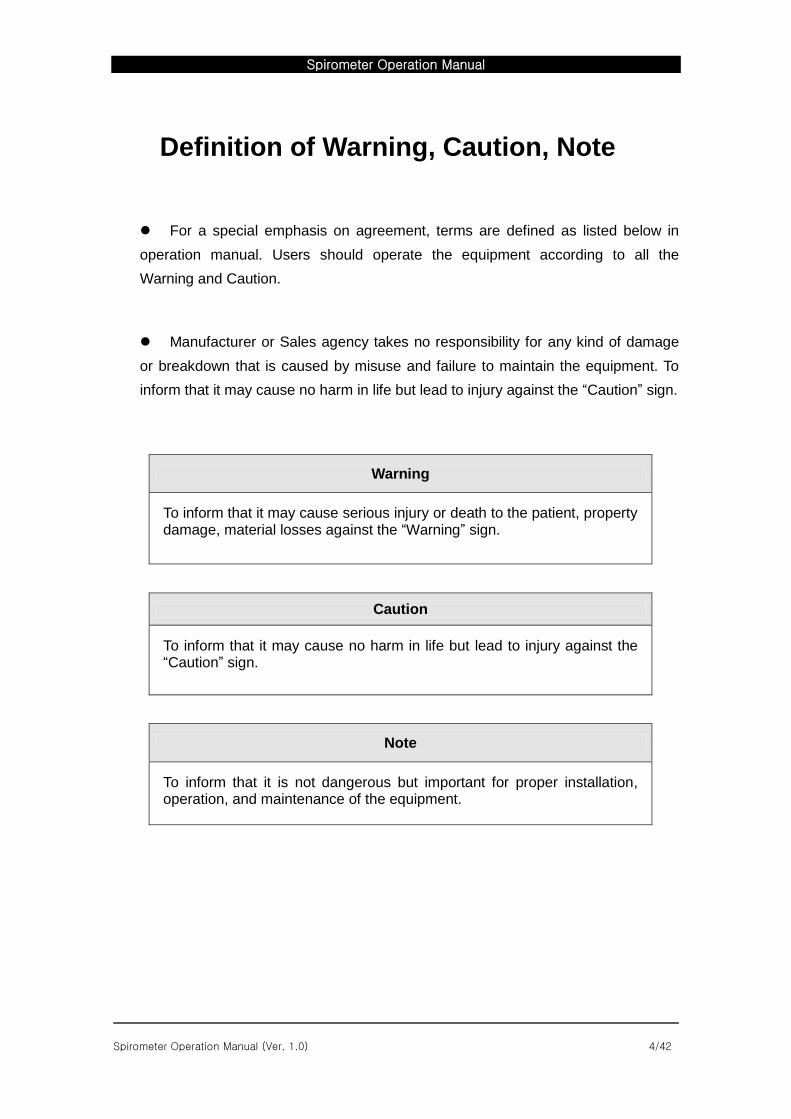
Definition of Warning, Caution, Note
For a special emphasis on agreement, terms are defined as listed below in
operation manual. Users should operate the equipment according to all the
Warning and Caution.
Manufacturer or Sales agency takes no responsibility for any kind of damage
or breakdown that is caused by misuse and failure to maintain the equipment. To
inform that it may cause no harm in life but lead to injury against the “Caution” sign.
Warning
To inform that it may cause serious injury or death to the patient, property damage, material losses against the “Warning” sign.
Caution
To inform that it may cause no harm in life but lead to injury against the “Caution” sign.
Note
To inform that it is not dangerous but important for proper installation, operation, and maintenance of the equipment.
Spirometer Operation Manual
Spirometer Operation Manual (Ver. 1.0) 5/42
Service Requirements
Refer servicing for equipment to Bionet Co., Ltd authorized service personnel. Any attempt to repair equipment under warranty will void that warranty.
It is the responsibility of users requiring service to report the need for service to Bionet Co., Ltd., or to one of their authorized agents.
Failure on the part of the responsible individual, hospital, or institution using this equipment to implement a satisfactory maintenance schedule may cause undue equipment failure and possible health hazards.
If there are any problems with the equipment, please follow the steps below :
Contact the Bionet Oversea Service Department immediately. After gathering the
model name, Serial Number, date of purchase, and description of the problem
contact Bionet with the information shown below.
Try to solve the problem over the phone with the service department personnel. If
the problem cannot be solved over the phone, the service personnel can came and
fix the problem directly.
Bionet or local distributor will make available on request circuit diagrams,
component part lists, descriptions, calibration instructions or other information
which will assist your appropriately qualified technical personnel to repair those
parts of equipment which are designated by Bionet as repairable.
Spirometer Operation Manual
Spirometer Operation Manual (Ver. 1.0) 6/42
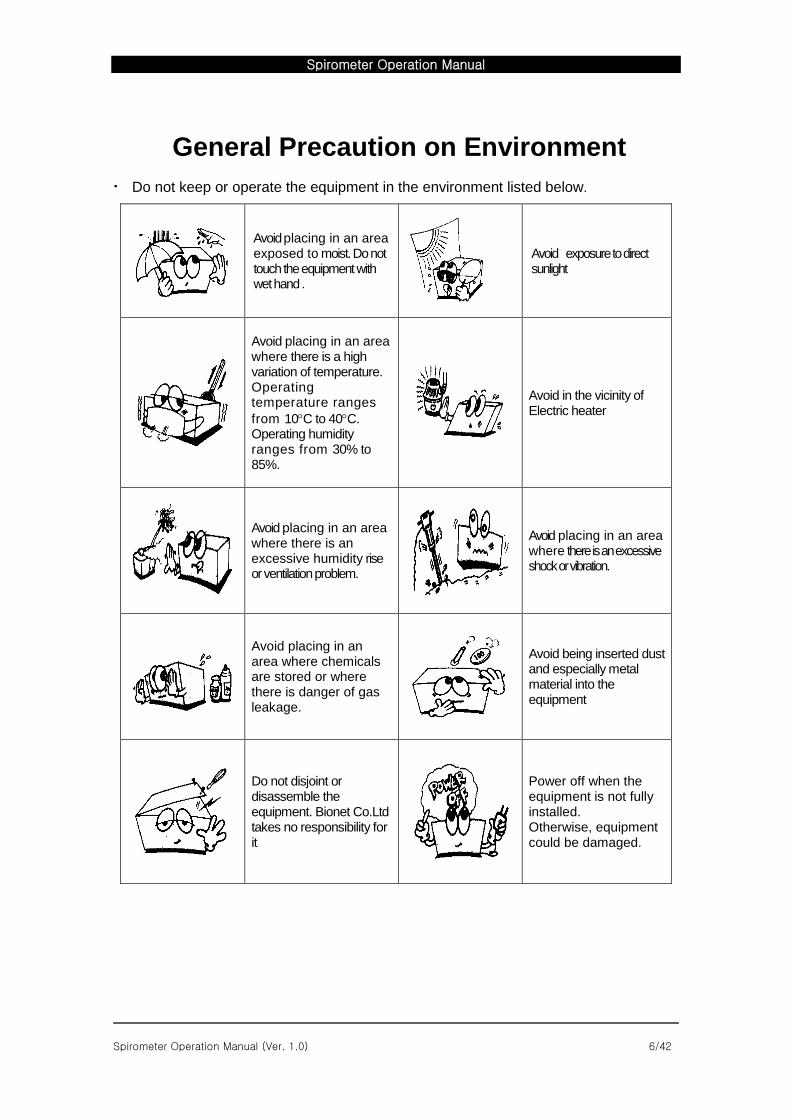
General Precaution on Environment
Do not keep or operate the equipment in the environment listed below.
Avoid placing in an area exposed to moist. Do not touch the equipment with wet hand .
Avoid exposure to direct sunlight
Avoid placing in an area where there is a high variation of temperature. Operating temperature ranges
from 10C to 40C. Operating humidity ranges from 30% to 85%.
Avoid in the vicinity of Electric heater
Avoid placing in an area where there is an excessive humidity rise or ventilation problem.
Avoid placing in an area where there is an excessive shock or vibration.
Avoid placing in an area where chemicals are stored or where there is danger of gas leakage.
Avoid being inserted dust and especially metal material into the equipment
Do not disjoint or disassemble the equipment. Bionet Co.Ltd takes no responsibility for it
Power off when the equipment is not fully installed. Otherwise, equipment could be damaged.
Spirometer Operation Manual
Spirometer Operation Manual (Ver. 1.0) 7/42
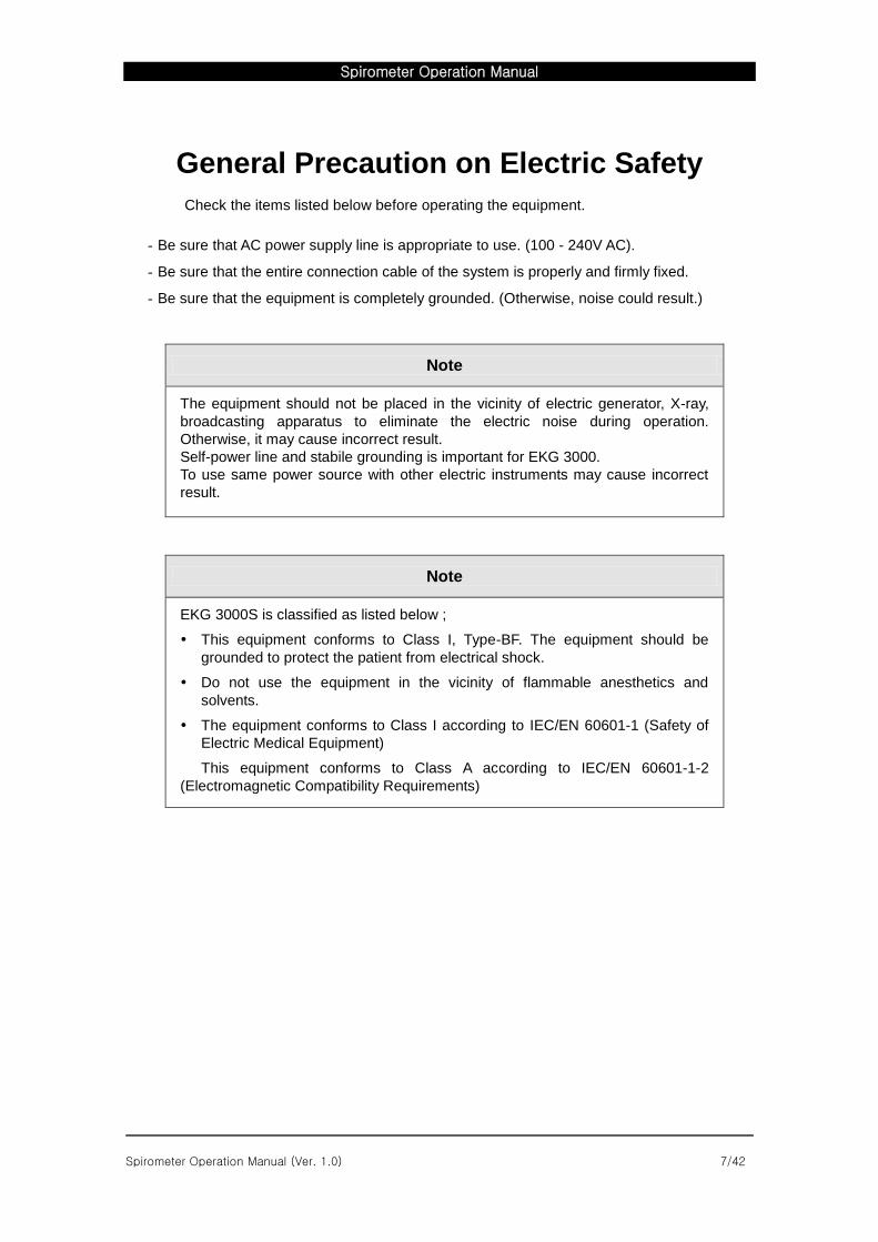
General Precaution on Electric Safety
Check the items listed below before operating the equipment.
- Be sure that AC power supply line is appropriate to use. (100 - 240V AC).
- Be sure that the entire connection cable of the system is properly and firmly fixed.
- Be sure that the equipment is completely grounded. (Otherwise, noise could result.)
Note
The equipment should not be placed in the vicinity of electric generator, X-ray,
broadcasting apparatus to eliminate the electric noise during operation.
Otherwise, it may cause incorrect result.
Self-power line and stabile grounding is important for EKG 3000.
To use same power source with other electric instruments may cause incorrect
result.
Note
EKG 3000S is classified as listed below ;
This equipment conforms to Class I, Type-BF. The equipment should be
grounded to protect the patient from electrical shock.
Do not use the equipment in the vicinity of flammable anesthetics and
solvents.
The equipment conforms to Class I according to IEC/EN 60601-1 (Safety of
Electric Medical Equipment)
This equipment conforms to Class A according to IEC/EN 60601-1-2
(Electromagnetic Compatibility Requirements)
Spirometer Operation Manual
Spirometer Operation Manual (Ver. 1.0) 8/42
Note
Diagnosis have to be confirmed by the doctor.
Note
Accessory equipment connected to the analog and digital interfaces must be
certified according to the respective IEC standards ( e.g. IEC 950 for data
processing equipment and IEC 601-1 for medical equipment ). Furthermore all
configurations shall comply with the system standard EN 60601-1-1:1993.
Everybody who connects additional equipment to the signal input part or signal
output part configures a medical system, and is therefore responsible that the
system complies with the requirements of the system standard IEC 601-1-
1:1993. If in doubt, consult the technical service department or your local
representative.Diagnosis have to be confirmed by the doctor.
Spirometer Operation Manual
Spirometer Operation Manual (Ver. 1.0) 9/42
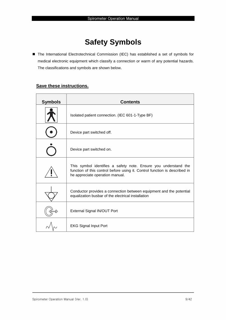
Safety Symbols
The International Electrotechnical Commission (IEC) has established a set of symbols for
medical electronic equipment which classify a connection or warm of any potential hazards.
The classifications and symbols are shown below.
Save these instructions.
Symbols Contents
Isolated patient connection. (IEC 601-1-Type BF)
Device part switched off.
Device part switched on.
This symbol identifies a safety note. Ensure you understand the
function of this control before using it. Control function is described in
he appreciate operation manual.
Conductor provides a connection between equipment and the potential
equalization busbar of the electrical installation
External Signal IN/OUT Port
EKG Signal Input Port
Spirometer Operation Manual
Spirometer Operation Manual (Ver. 1.0) 10/42
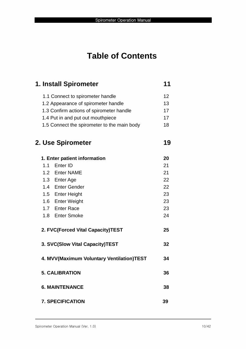
Table of Contents
1. Install Spirometer 11
1.1 Connect to spirometer handle 12
1.2 Appearance of spirometer handle 13
1.3 Confirm actions of spirometer handle 17
1.4 Put in and put out mouthpiece 17
1.5 Connect the spirometer to the main body 18
2. Use Spirometer 19
1. Enter patient information 20
1.1 Enter ID 21
1.2 Enter NAME 21
1.3 Enter Age 22
1.4 Enter Gender 22
1.5 Enter Height 23
1.6 Enter Weight 23
1.7 Enter Race 23
1.8 Enter Smoke 24
2. FVC(Forced Vital Capacity)TEST 25
3. SVC(Slow Vital Capacity)TEST 32
4. MVV(Maximum Voluntary Ventilation)TEST 34
5. CALIBRATION 36
6. MAINTENANCE 38
7. SPECIFICATION 39
Spirometer Operation Manual
Spirometer Operation Manual (Ver. 1.0) 11/42
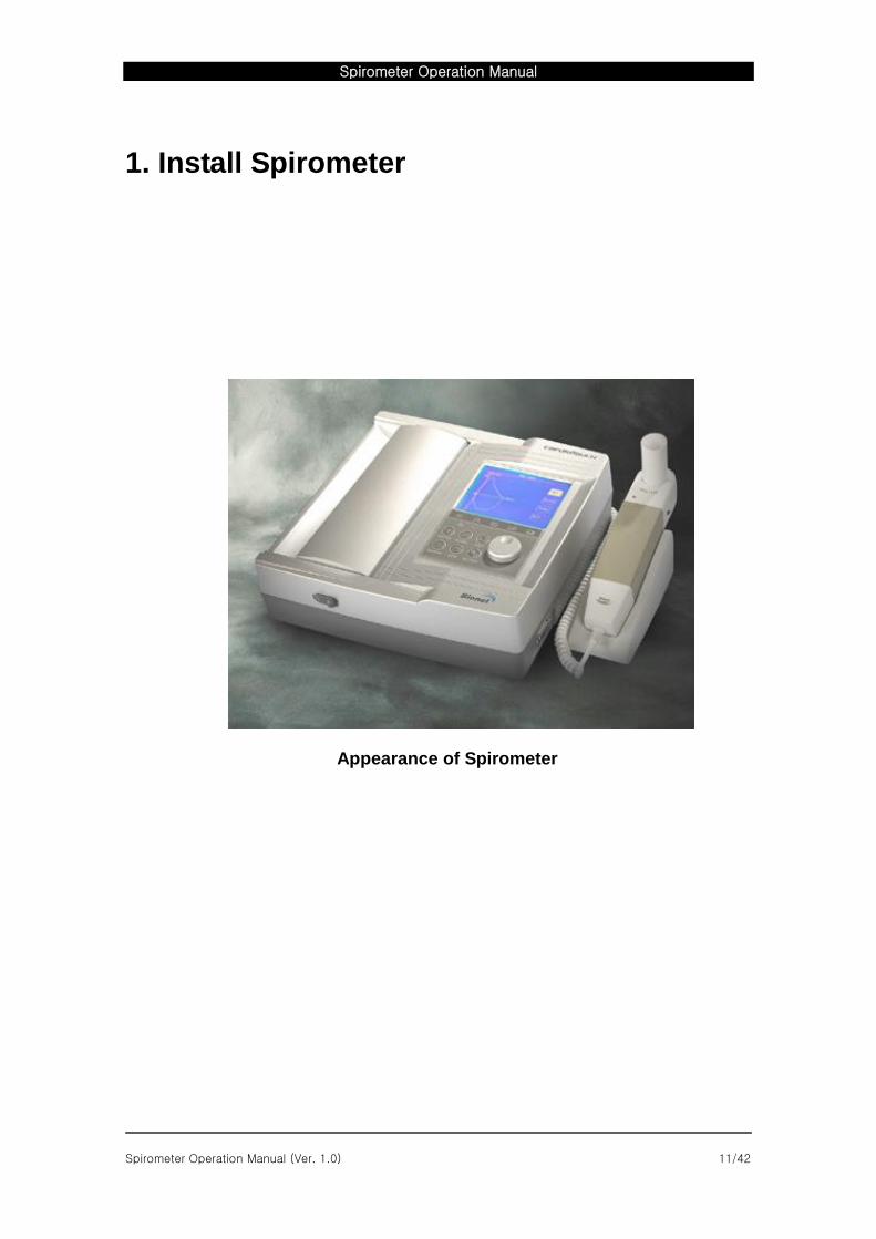
1. Install Spirometer
Appearance of Spirometer
Spirometer Operation Manual
Spirometer Operation Manual (Ver. 1.0) 12/42
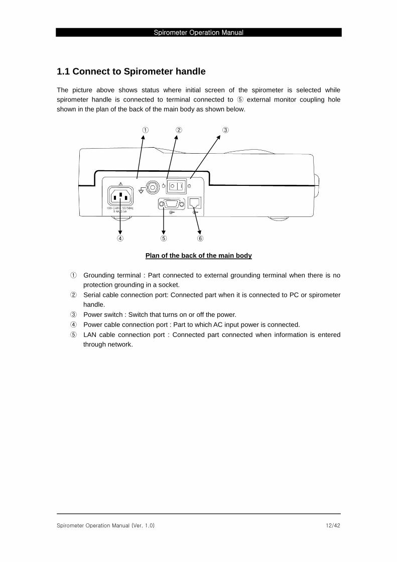
1.1 Connect to Spirometer handle
The picture above shows status where initial screen of the spirometer is selected while
spirometer handle is connected to terminal connected to ⑤ external monitor coupling hole
shown in the plan of the back of the main body as shown below.
① ② ③
④ ⑤ ⑥
Plan of the back of the main body
① Grounding terminal : Part connected to external grounding terminal when there is no
protection grounding in a socket.
② Serial cable connection port: Connected part when it is connected to PC or spirometer
handle.
③ Power switch : Switch that turns on or off the power.
④ Power cable connection port : Part to which AC input power is connected.
⑤ LAN cable connection port : Connected part connected when information is entered
through network.
Spirometer Operation Manual
Spirometer Operation Manual (Ver. 1.0) 13/42
1.2 Appearance of spirometer handle
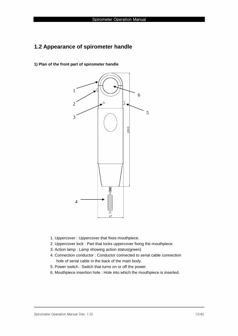
1) Plan of the front part of spirometer handle
1. Uppercover : Uppercover that fixes mouthpiece.
2. Uppercover lock : Part that locks uppercover fixing the mouthpiece.
3. Action lamp : Lamp showing action status(green)
4. Connection conductor : Conductor connected to serial cable connection
hole of serial cable in the back of the main body.
5. Power switch : Switch that turns on or off the power.
6. Mouthpiece insertion hole : Hole into which the mouthpiece is inserted.
2
3
4
1
5
6
Spirometer Operation Manual
Spirometer Operation Manual (Ver. 1.0) 14/42
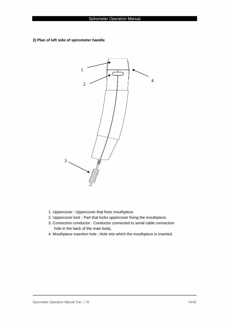
2) Plan of left side of spirometer handle
1. Uppercover : Uppercover that fixes mouthpiece.
2. Uppercover lock : Part that locks uppercover fixing the mouthpiece.
3. Connection conductor : Conductor connected to serial cable connection
hole in the back of the main body.
4. Mouthpiece insertion hole : Hole into which the mouthpiece is inserted.
2
3
1
4
Spirometer Operation Manual
Spirometer Operation Manual (Ver. 1.0) 15/42
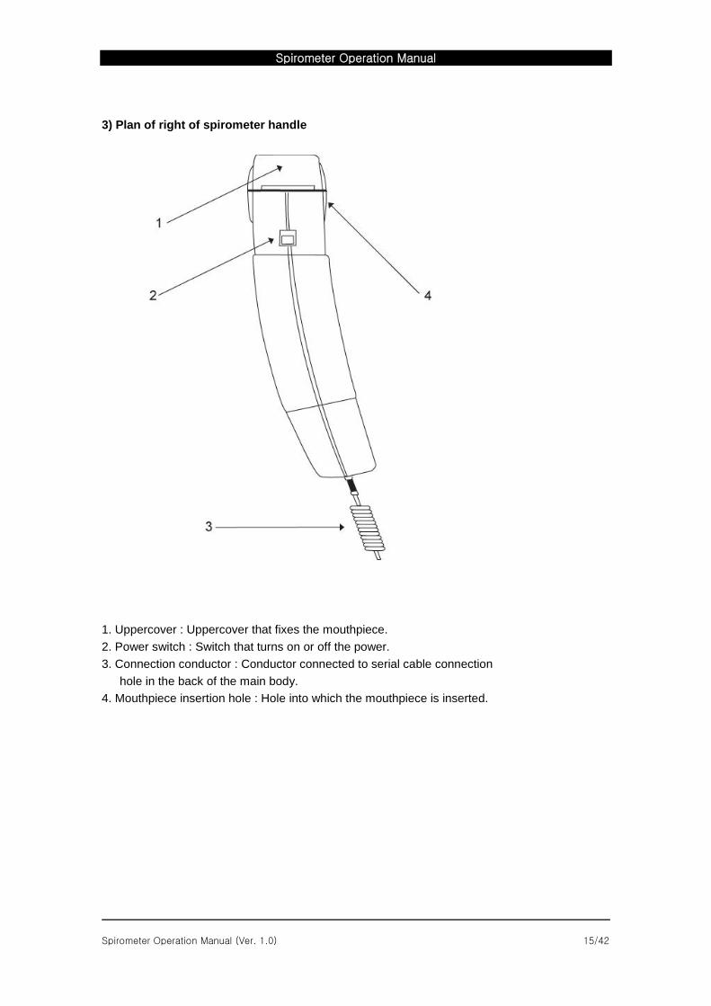
3) Plan of right of spirometer handle
1. Uppercover : Uppercover that fixes the mouthpiece.
2. Power switch : Switch that turns on or off the power.
3. Connection conductor : Conductor connected to serial cable connection
hole in the back of the main body.
4. Mouthpiece insertion hole : Hole into which the mouthpiece is inserted.
Spirometer Operation Manual
Spirometer Operation Manual (Ver. 1.0) 16/42
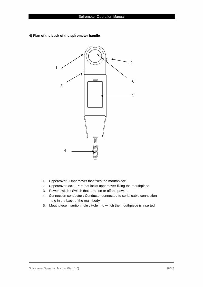
4) Plan of the back of the spirometer handle
1. Uppercover : Uppercover that fixes the mouthpiece.
2. Uppercover lock : Part that locks uppercover fixing the mouthpiece.
3. Power switch : Switch that turns on or off the power.
4. Connection conductor : Conductor connected to serial cable connection
hole in the back of the main body.
5. Mouthpiece insertion hole : Hole into which the mouthpiece is inserted.
2
3
4
1
5
6
Spirometer Operation Manual
Spirometer Operation Manual (Ver. 1.0) 17/42
1.3 Confirm actions of spirometer handle
if you turn on power switch in the right side of spirometer handle, the lamp turns green for three
seconds before it blinks at intervals of three seconds and it indicates that the spirometer handle
normally operates.
1.4 Put in and out mouthpiece
Fix disposable mouthpiece in the upper side of the spirometer handle to take measurement.
First, press ‘Uppercover lock’ in the upper left side of spirometer handle and open semicircle
uppercover and insert the mouthpiece into a groove made in open side. And then, close the
uppercover again by giving a little pressure. In order to fix the mouthpiece correctly, pipe in the
front side of the spirometer handle should be longer than that in the back side.
※The mouthpiece is disposable.
※Refer to plan of the spirometer handle.
Caution
Please, Don’t close the upper cover,
a condition of pushing down the Cover Lock Switch.
Spirometer Operation Manual
Spirometer Operation Manual (Ver. 1.0) 18/42
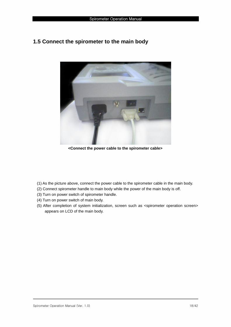
1.5 Connect the spirometer to the main body
<Connect the power cable to the spirometer cable>
(1) As the picture above, connect the power cable to the spirometer cable in the main body.
(2) Connect spirometer handle to main body while the power of the main body is off.
(3) Turn on power switch of spirometer handle.
(4) Turn on power switch of main body.
(5) After completion of system initialization, screen such as <spirometer operation screen>
appears on LCD of the main body.
Spirometer Operation Manual
Spirometer Operation Manual (Ver. 1.0) 19/42
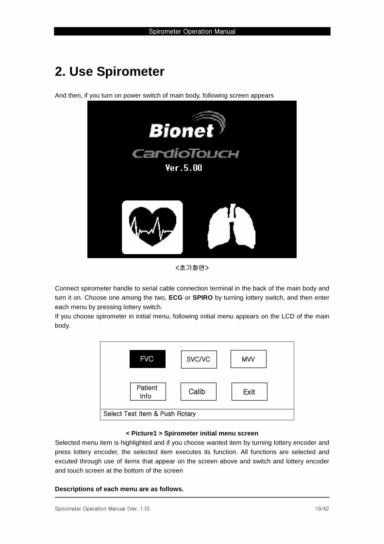
2. Use Spirometer
And then, if you turn on power switch of main body, following screen appears
<초기화면>
Connect spirometer handle to serial cable connection terminal in the back of the main body and
turn it on. Choose one among the two, ECG or SPIRO by turning lottery switch, and then enter
each menu by pressing lottery switch.
If you choose spirometer in initial menu, following initial menu appears on the LCD of the main
body.
Select Test Item & Push Rotary
< Picture1 > Spirometer initial menu screen
Selected menu item is highlighted and if you choose wanted item by turning lottery encoder and
press lottery encoder, the selected item executes its function. All functions are selected and
excuted through use of items that appear on the screen above and switch and lottery encoder
and touch screen at the bottom of the screen
Descriptions of each menu are as follows.
FVC SVC/VC MVV
Patient
Info Calib Exit
Spirometer Operation Manual
Spirometer Operation Manual (Ver. 1.0) 20/42
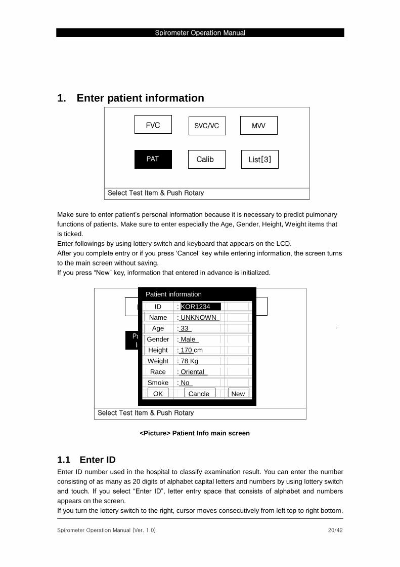
1. Enter patient information
Select Test Item & Push Rotary
Make sure to enter patient’s personal information because it is necessary to predict pulmonary
functions of patients. Make sure to enter especially the Age, Gender, Height, Weight items that
is ticked.
Enter followings by using lottery switch and keyboard that appears on the LCD.
After you complete entry or if you press ‘Cancel’ key while entering information, the screen turns
to the main screen without saving.
If you press “New” key, information that entered in advance is initialized.
Select Test Item & Push Rotary
<Picture> Patient Info main screen
1.1 Enter ID
Enter ID number used in the hospital to classify examination result. You can enter the number
consisting of as many as 20 digits of alphabet capital letters and numbers by using lottery switch
and touch. If you select “Enter ID”, letter entry space that consists of alphabet and numbers
appears on the screen.
If you turn the lottery switch to the right, cursor moves consecutively from left top to right bottom.
FVC SVC/VC MVV
PAT Calib List[3]
FVC SVC/VC MVV
Patient
Info Calib Exit
Patient information
ID : KOR1234
Name : UNKNOWN
Age : 33
Gender : Male
Height : 170 cm
Weight : 78 Kg
Race : Oriental
Smoke : No
OK Cancle New
Spirometer Operation Manual
Spirometer Operation Manual (Ver. 1.0) 21/42
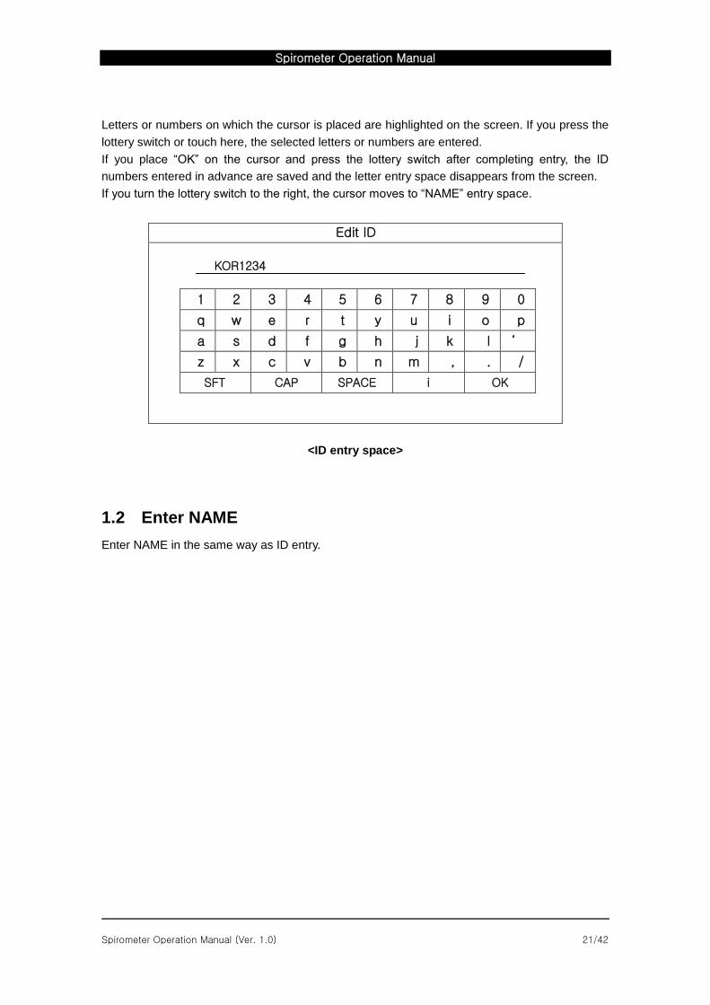
Letters or numbers on which the cursor is placed are highlighted on the screen. If you press the
lottery switch or touch here, the selected letters or numbers are entered.
If you place “OK” on the cursor and press the lottery switch after completing entry, the ID
numbers entered in advance are saved and the letter entry space disappears from the screen.
If you turn the lottery switch to the right, the cursor moves to “NAME” entry space.
Edit ID
KOR1234
1 2 3 4 5 6 7 8 9 0
q w e r t y u i o p
a s d f g h j k l ‘
z x c v b n m , . /
SFT CAP SPACE i OK
<ID entry space>
1.2 Enter NAME
Enter NAME in the same way as ID entry.
Spirometer Operation Manual
Spirometer Operation Manual (Ver. 1.0) 22/42
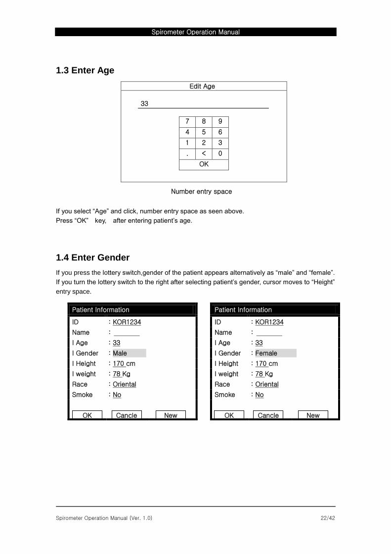
1.3 Enter Age
Edit Age
33
7 8 9
4 5 6
1 2 3
. < 0
OK
Number entry space
If you select “Age” and click, number entry space as seen above.
Press “OK” key, after entering patient’s age.
1.4 Enter Gender
If you press the lottery switch,gender of the patient appears alternatively as “male” and “female”.
If you turn the lottery switch to the right after selecting patient’s gender, cursor moves to “Height”
entry space.
Patient Information
ID : KOR1234
Name :
I Age : 33
I Gender : Male
I Height : 170 cm
I weight : 78 Kg
Race : Oriental
Smoke : No
Patient Information
ID : KOR1234
Name :
I Age : 33
I Gender : Female
I Height : 170 cm
I weight : 78 Kg
Race : Oriental
Smoke : No
OK
Cancle
New
OK
Cancle
New
Spirometer Operation Manual
Spirometer Operation Manual (Ver. 1.0) 23/42
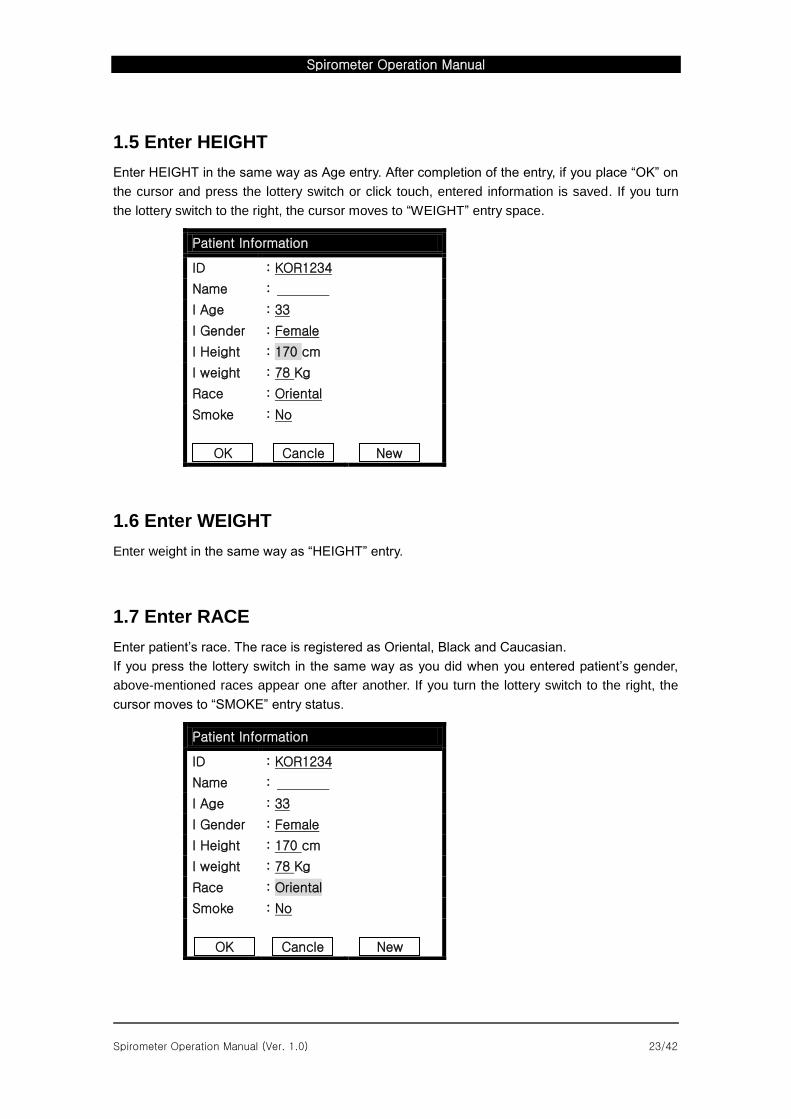
1.5 Enter HEIGHT
Enter HEIGHT in the same way as Age entry. After completion of the entry, if you place “OK” on
the cursor and press the lottery switch or click touch, entered information is saved. If you turn
the lottery switch to the right, the cursor moves to “WEIGHT” entry space.
1.6 Enter WEIGHT
Enter weight in the same way as “HEIGHT” entry.
1.7 Enter RACE
Enter patient’s race. The race is registered as Oriental, Black and Caucasian.
If you press the lottery switch in the same way as you did when you entered patient’s gender,
above-mentioned races appear one after another. If you turn the lottery switch to the right, the
cursor moves to “SMOKE” entry status.
Patient Information
ID : KOR1234
Name :
I Age : 33
I Gender : Female
I Height : 170 cm
I weight : 78 Kg
Race : Oriental
Smoke : No
Patient Information
ID : KOR1234
Name :
I Age : 33
I Gender : Female
I Height : 170 cm
I weight : 78 Kg
Race : Oriental
Smoke : No
Male
OK
Cancle
New
OK
Cancle
New
Spirometer Operation Manual
Spirometer Operation Manual (Ver. 1.0) 24/42
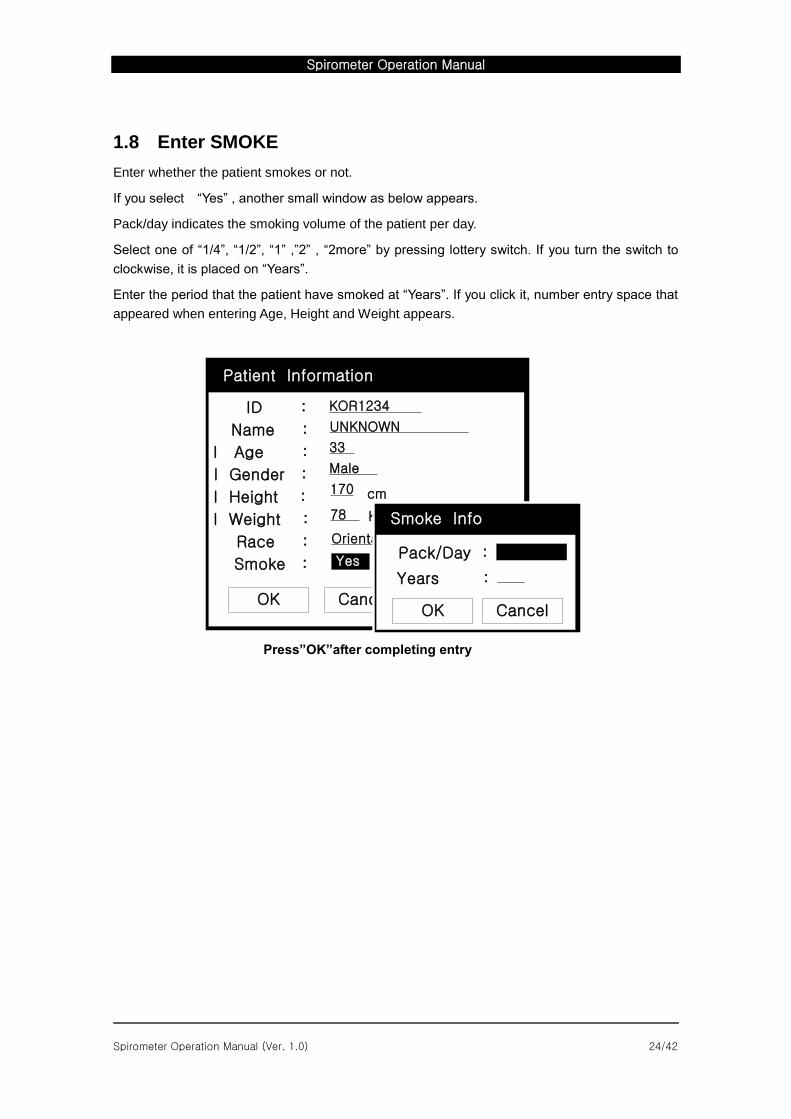
1.8 Enter SMOKE
Enter whether the patient smokes or not.
If you select “Yes” , another small window as below appears.
Pack/day indicates the smoking volume of the patient per day.
Select one of “1/4”, “1/2”, “1” ,”2” , “2more” by pressing lottery switch. If you turn the switch to
clockwise, it is placed on “Years”.
Enter the period that the patient have smoked at “Years”. If you click it, number entry space that
appeared when entering Age, Height and Weight appears.
SVC/VC MVV
CalibGo to EKG
ID :
Name :
I Age :
I Gender :
I Height :
I Weight :
Race :
Smoke :
KOR1234
UNKNOWN
33
Male
cm170
Kg78
Oriental
OK Cancel New
Patient Information
OK Cancel
Years :
Pack/Day :
Smoke Info
Yes
Press”OK”after completing entry
Spirometer Operation Manual
Spirometer Operation Manual (Ver. 1.0) 25/42
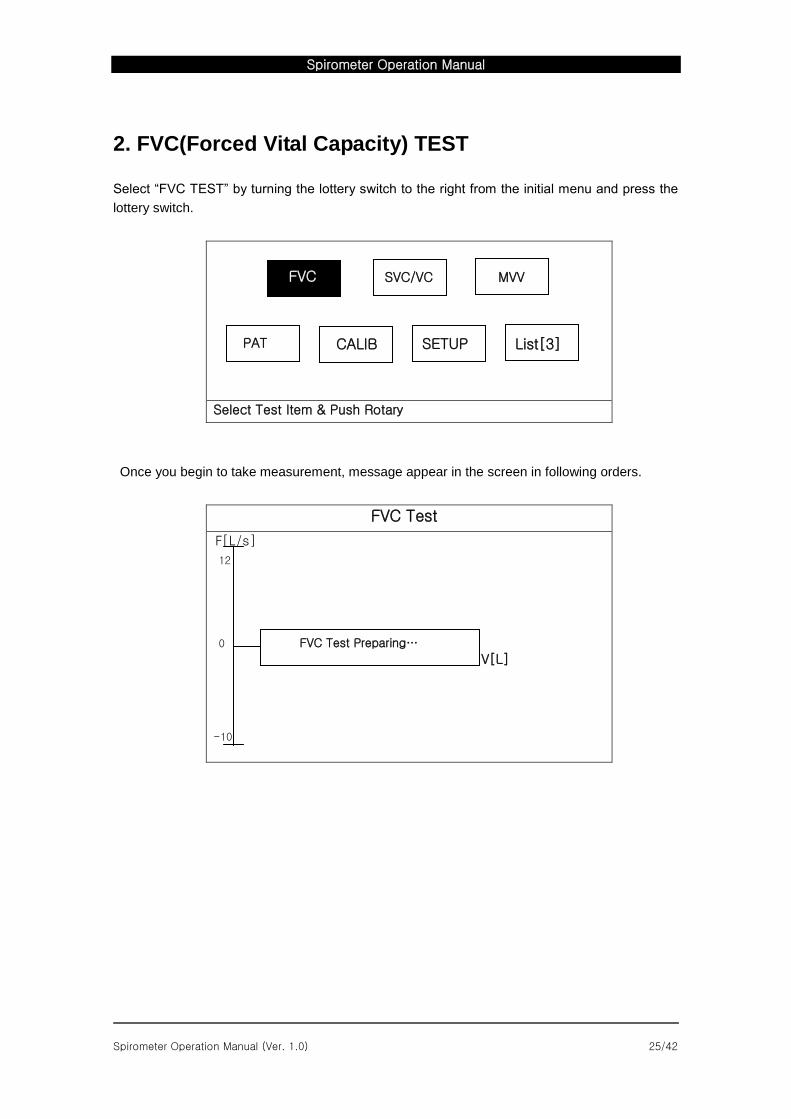
2. FVC(Forced Vital Capacity) TEST
Select “FVC TEST” by turning the lottery switch to the right from the initial menu and press the
lottery switch.
Select Test Item & Push Rotary
Once you begin to take measurement, message appear in the screen in following orders.
FVC Test
F[L/s]
12
0
V[L]
-10
FVC SVC/VC MVV
PAT CALIB
FVC Test Preparing…
SETUP List[3]
Spirometer Operation Manual
Spirometer Operation Manual (Ver. 1.0) 26/42
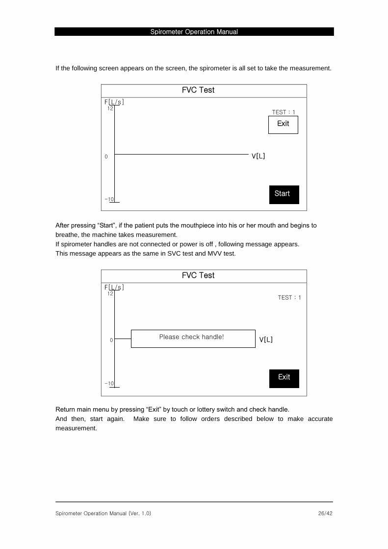
If the following screen appears on the screen, the spirometer is all set to take the measurement.
FVC Test
F[L/s]
TEST : 1
0 V[L]
After pressing “Start”, if the patient puts the mouthpiece into his or her mouth and begins to
breathe, the machine takes measurement.
If spirometer handles are not connected or power is off , following message appears.
This message appears as the same in SVC test and MVV test.
FVC Test
F[L/s]
TEST : 1
0 V[L]
Return main menu by pressing “Exit” by touch or lottery switch and check handle.
And then, start again. Make sure to follow orders described below to make accurate
measurement.
Exit
Start
12
-10
Exit
12
-10
Please check handle!
Spirometer Operation Manual
Spirometer Operation Manual (Ver. 1.0) 27/42
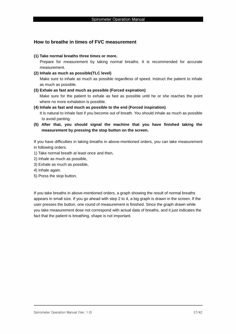
How to breathe in times of FVC measurement
(1) Take normal breaths three times or more.
Prepare for measurement by taking normal breaths. It is recommended for accurate
measurement.
(2) Inhale as much as possible(TLC level)
Make sure to inhale as much as possible regardless of speed. Instruct the patient to inhale
as much as possible.
(3) Exhale as fast and much as possible (Forced expiration)
Make sure for the patient to exhale as fast as possible until he or she reaches the point
where no more exhalation is possible.
(4) Inhale as fast and much as possible to the end (Forced inspiration)
It is natural to inhale fast if you become out of breath. You should inhale as much as possible
to avoid panting.
(5) After that, you should signal the machine that you have finished taking the
measurement by pressing the stop button on the screen.
If you have difficulties in taking breaths in above-mentioned orders, you can take measurement
in following orders.
1) Take normal breath at least once and then,
2) Inhale as much as possible,
3) Exhale as much as possible,
4) Inhale again.
5) Press the stop button.
If you take breaths in above-mentioned orders, a graph showing the result of normal breaths
appears in small size. If you go ahead with step 2 to 4, a big graph is drawn in the screen. If the
user presses the button, one round of measurement is finished. Since the graph drawn while
you take measurement dose not correspond with actual data of breaths, and it just indicates the
fact that the patient is breathing, shape is not important.
Spirometer Operation Manual
Spirometer Operation Manual (Ver. 1.0) 28/42
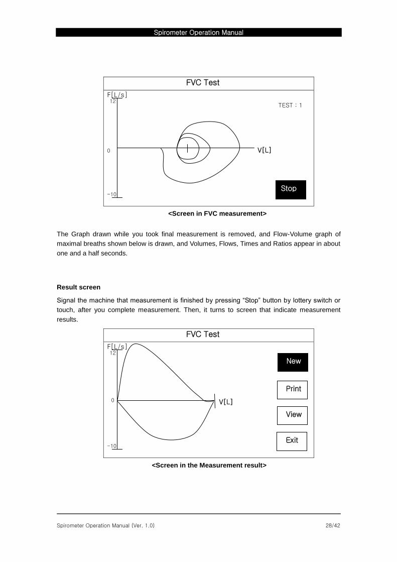
FVC Test
F[L/s]
TEST : 1
0 V[L]
<Screen in FVC measurement>
The Graph drawn while you took final measurement is removed, and Flow-Volume graph of
maximal breaths shown below is drawn, and Volumes, Flows, Times and Ratios appear in about
one and a half seconds.
Result screen
Signal the machine that measurement is finished by pressing “Stop” button by lottery switch or
touch, after you complete measurement. Then, it turns to screen that indicate measurement
results.
FVC Test
F[L/s]
V[L]
<Screen in the Measurement result>
Stop
12
-10
New
Exit
12
-10
View
0
Spirometer Operation Manual
Spirometer Operation Manual (Ver. 1.0) 29/42
If you have difficulties in taking measurement in above-mentioned orders, you can take
measurement in following orders.
1) Take normal breath at least one time and then
2) Inhale as much as possible,
3) Exhale as much as possible,
4) Inhale again.
5) Press the lottery button.
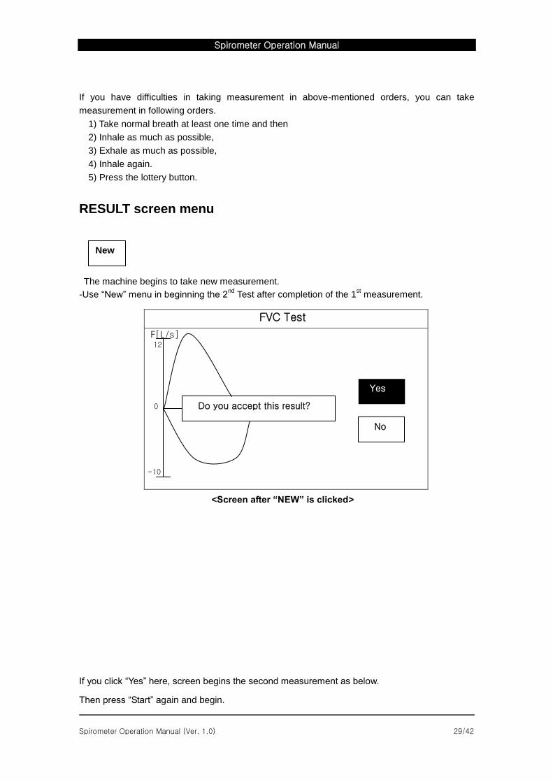
RESULT screen menu
The machine begins to take new measurement.
-Use “New” menu in beginning the 2nd
Test after completion of the 1st measurement.
FVC Test
F[L/s]
0
<Screen after “NEW” is clicked>
If you click “Yes” here, screen begins the second measurement as below.
Then press “Start” again and begin.
Do you accept this result?
Yes
No
-10
12
New
Spirometer Operation Manual
Spirometer Operation Manual (Ver. 1.0) 30/42
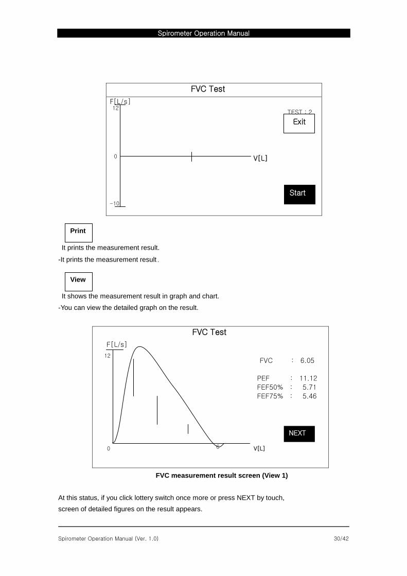
FVC Test
F[L/s]
TEST : 2
V[L]
It prints the measurement result.
-It prints the measurement result.
It shows the measurement result in graph and chart.
-You can view the detailed graph on the result.
FVC Test
F[L/s]
FVC : 6.05
PEF : 11.12
FEF50% : 5.71
FEF75% : 5.46
0 V[L]
FVC measurement result screen (View 1)
At this status, if you click lottery switch once more or press NEXT by touch,
screen of detailed figures on the result appears.
Start
12
-10
0
Exit
NEXT
6
12
View
Spirometer Operation Manual
Spirometer Operation Manual (Ver. 1.0) 31/42
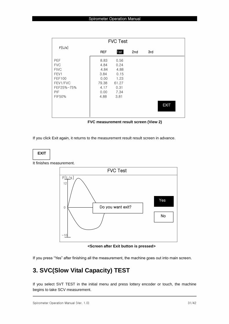
FVC Test
F[L/s]
REF 1st 2nd 3rd
PEF 8.83 0.56
FVC 4.84 0.24
FIVC 4.84 4.88
FEV1 3.84 0.15
FEF100 0.00 1.23
FEV1/FVC 79.38 61.27
FEF25%-75% 4.17 0.31
PIF 0.00 7.34
FIF50% 4.88 3.81
FVC measurement result screen (View 2)
If you click Exit again, it returns to the measurement result result screen in advance.
It finishes measurement.
FVC Test
F[L/s]
12
0
<Screen after Exit button is pressed>
If you press “Yes” after finishing all the measurement, the machine goes out into main screen.
3. SVC(Slow Vital Capacity) TEST
If you select SVT TEST in the initial menu and press lottery encoder or touch, the machine
begins to take SCV measurement.
EXIT
Do you want exit?
Yes
No
-10
EXIT
Spirometer Operation Manual
Spirometer Operation Manual (Ver. 1.0) 32/42
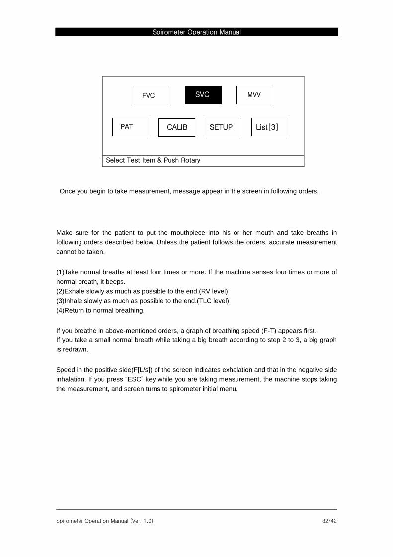
Select Test Item & Push Rotary
Once you begin to take measurement, message appear in the screen in following orders.
Make sure for the patient to put the mouthpiece into his or her mouth and take breaths in
following orders described below. Unless the patient follows the orders, accurate measurement
cannot be taken.
(1)Take normal breaths at least four times or more. If the machine senses four times or more of
normal breath, it beeps.
(2)Exhale slowly as much as possible to the end.(RV level)
(3)Inhale slowly as much as possible to the end.(TLC level)
(4)Return to normal breathing.
If you breathe in above-mentioned orders, a graph of breathing speed (F-T) appears first.
If you take a small normal breath while taking a big breath according to step 2 to 3, a big graph
is redrawn.
Speed in the positive side(F[L/s]) of the screen indicates exhalation and that in the negative side
inhalation. If you press “ESC” key while you are taking measurement, the machine stops taking
the measurement, and screen turns to spirometer initial menu.
MVV
PAT CALIB SETUP List[3]
SVC FVC
Spirometer Operation Manual
Spirometer Operation Manual (Ver. 1.0) 33/42
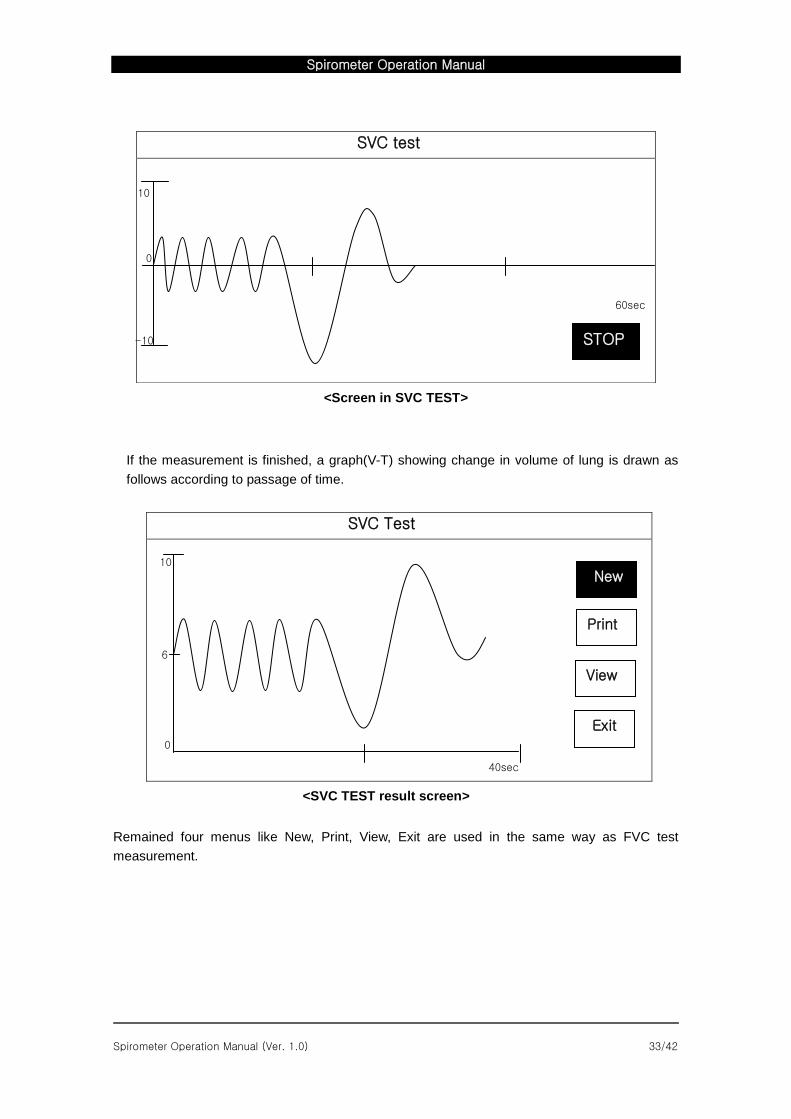
<Screen in SVC TEST>
If the measurement is finished, a graph(V-T) showing change in volume of lung is drawn as
follows according to passage of time.
SVC Test
40sec
<SVC TEST result screen>
Remained four menus like New, Print, View, Exit are used in the same way as FVC test
measurement.
SVC test
New
Exit
View
10
0
6
STOP
60sec
-10
0
10
STOP
Spirometer Operation Manual
Spirometer Operation Manual (Ver. 1.0) 34/42
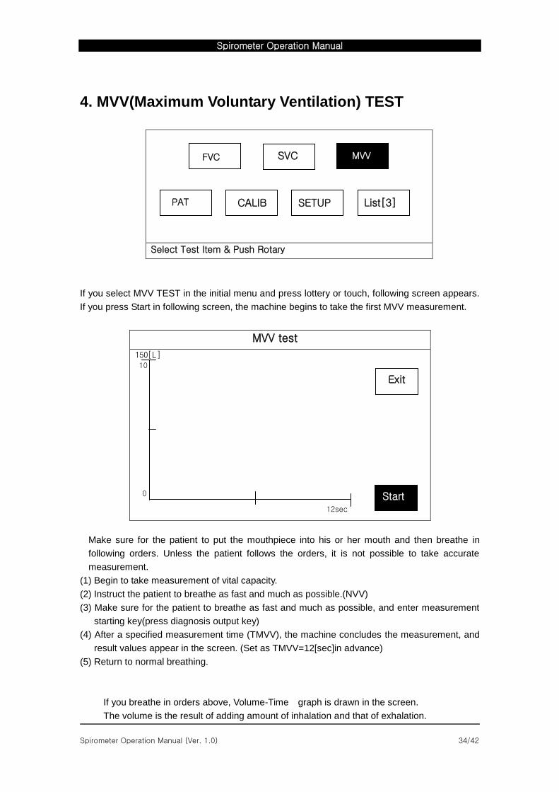
4. MVV(Maximum Voluntary Ventilation) TEST
Select Test Item & Push Rotary
If you select MVV TEST in the initial menu and press lottery or touch, following screen appears.
If you press Start in following screen, the machine begins to take the first MVV measurement.
MVV test
150[L]
12sec
Make sure for the patient to put the mouthpiece into his or her mouth and then breathe in
following orders. Unless the patient follows the orders, it is not possible to take accurate
measurement.
(1) Begin to take measurement of vital capacity.
(2) Instruct the patient to breathe as fast and much as possible.(NVV)
(3) Make sure for the patient to breathe as fast and much as possible, and enter measurement
starting key(press diagnosis output key)
(4) After a specified measurement time (TMVV), the machine concludes the measurement, and
result values appear in the screen. (Set as TMVV=12[sec]in advance)
(5) Return to normal breathing.
If you breathe in orders above, Volume-Time graph is drawn in the screen.
The volume is the result of adding amount of inhalation and that of exhalation.
Start
Exit
10
0
MVV
PAT CALIB SETUP List[3]
SVC FVC
Spirometer Operation Manual
Spirometer Operation Manual (Ver. 1.0) 35/42
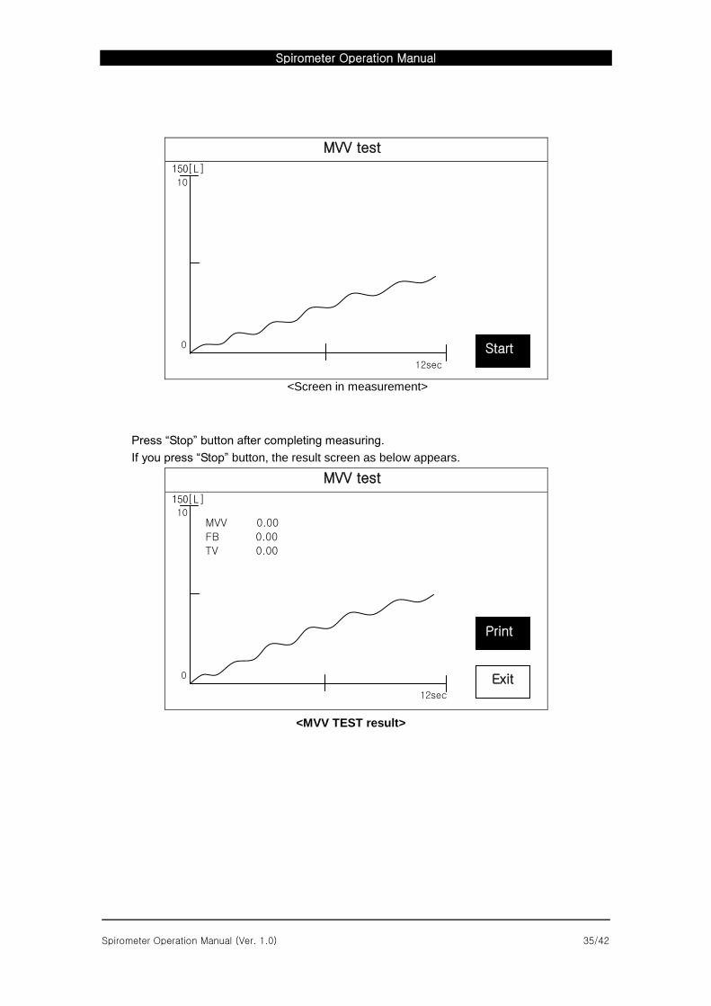
MVV test
150[L]
12sec
<Screen in measurement>
Press “Stop” button after completing measuring.
If you press “Stop” button, the result screen as below appears.
MVV test
150[L]
12sec
<MVV TEST result>
Start
10
0
Exit
10
0
MVV 0.00
FB 0.00
TV 0.00
Spirometer Operation Manual
Spirometer Operation Manual (Ver. 1.0) 36/42
5. CALIBRATION
CALIBRTION should be conducted once everyday to maintain accuracy of the measurement.
(calibrator should be purchased optionally by user)
If the correct result and existing result are within a margin of +/-5%,
new correction result does not have to be applied.
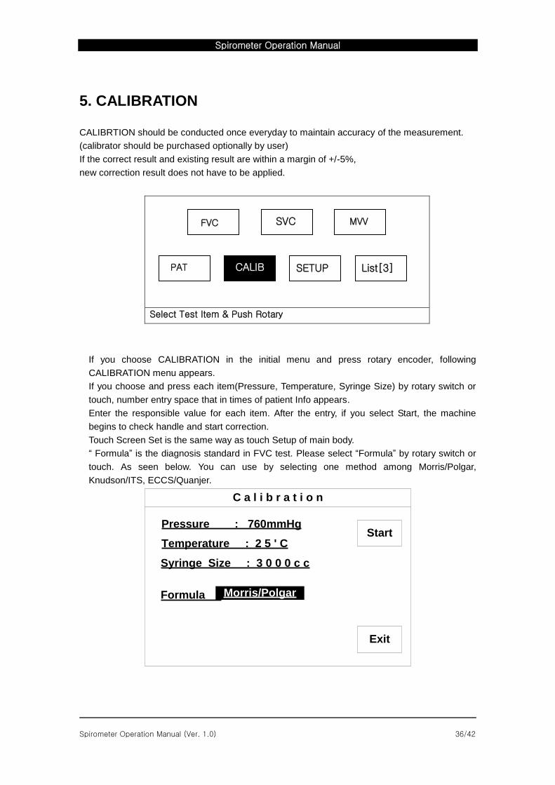
Select Test Item & Push Rotary
If you choose CALIBRATION in the initial menu and press rotary encoder, following
CALIBRATION menu appears.
If you choose and press each item(Pressure, Temperature, Syringe Size) by rotary switch or
touch, number entry space that in times of patient Info appears.
Enter the responsible value for each item. After the entry, if you select Start, the machine
begins to check handle and start correction.
Touch Screen Set is the same way as touch Setup of main body.
“ Formula” is the diagnosis standard in FVC test. Please select “Formula” by rotary switch or
touch. As seen below. You can use by selecting one method among Morris/Polgar,
Knudson/ITS, ECCS/Quanjer.
C a l i b r a t i o n
Pressure : 760mmHg
Morris/Polgar
Temperature : 2 5 ' C
Syringe Size : 3 0 0 0 c c
Start
Exit
Formula :
MVV
PAT CALIB SETUP List[3]
SVC FVC
Spirometer Operation Manual
Spirometer Operation Manual (Ver. 1.0) 37/42
Description for each Formula were as follows.
Standards Formula Description
USA and Canada Morris/Polgar Previous method used to diagnosis
Knudson/ITS Most common method/extended formula
Outside the USA ECCS/Quanjer Widely used method in Europe/Pediatric formula
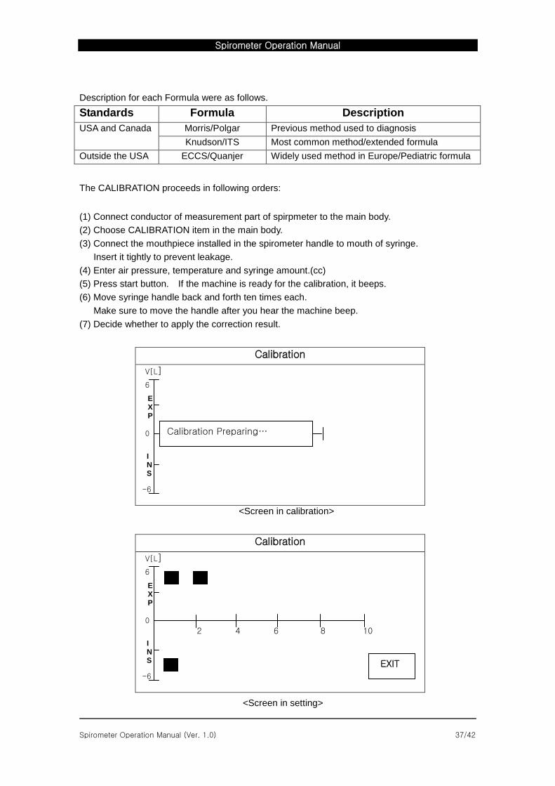
The CALIBRATION proceeds in following orders:
(1) Connect conductor of measurement part of spirpmeter to the main body.
(2) Choose CALIBRATION item in the main body.
(3) Connect the mouthpiece installed in the spirometer handle to mouth of syringe.
Insert it tightly to prevent leakage.
(4) Enter air pressure, temperature and syringe amount.(cc)
(5) Press start button. If the machine is ready for the calibration, it beeps.
(6) Move syringe handle back and forth ten times each.
Make sure to move the handle after you hear the machine beep.
(7) Decide whether to apply the correction result.
Calibration
V[L]
6
0
<Screen in calibration>
Calibration
V[L]
6
0
2 4 6 8 10
<Screen in setting>
-6
E X P
I N S
Calibration Preparing…
-6
E X P
I N S
EXIT
Spirometer Operation Manual
Spirometer Operation Manual (Ver. 1.0) 38/42
Everytime the syringe moves, a dot appears in the screen everytime one action is taken.
Make sure to take subsequent action after a dot appears in the screen for accurate calibration.
If you move the syringe ten times, prior volume measurement result and margin of error(%)
appear in the screen. If the dot doesn’t appear in the screen whenever the syringe moves
please reset the calibration and then restart. The procedure of reset is as follows. Press Start]
and Calib menu and then select Exit. If so, the reset will be done showing 100% range of difference.
If you go through procedures of confirming whether to apply new coefficient,result values are
entered into the measurement part of the spirometer, and the initial menu appears.
Otherwise, the initial menu immediately appears.
If the touch screen dosen’t work properly please enter ‘Touch Screen Set’ by using rotary key
and then please touch ‘<- Touch rectangle’ which appears on the left of the top and touch
‘Touch rectangle’ appears on the right of the bottom.
6. MAINTENANCE
1) Maintenance and Cleaning
You can keep the device clean in many different ways. Use the following recommendations to
avoid the damage or stain to the machine. If the material (not approved material) that may
cause damage to the product is used, the product is not guaranteed even within the period of
guarantee is not expired.
Note
Check the main unit and probes thoroughly after cleaning. Do not use the old and damaged equipment.
To keep the machine clean, apply alcohol on a soft cloth and scrub the body and the measuring probes once a month. Do not use lacquer, thinner, ethylene, or the oxidizing substance. Keep the cable from dust or stain. Wipe the cable with a soaked cloth that is wet with warm
water (40C/ 104F), and with the clinical alcohol once a week. Do not soak the machine or the probe cable into any liquid or detergent. Keep the machine or the probe cable away from any liquid.
Spirometer Operation Manual
Spirometer Operation Manual (Ver. 1.0) 39/42
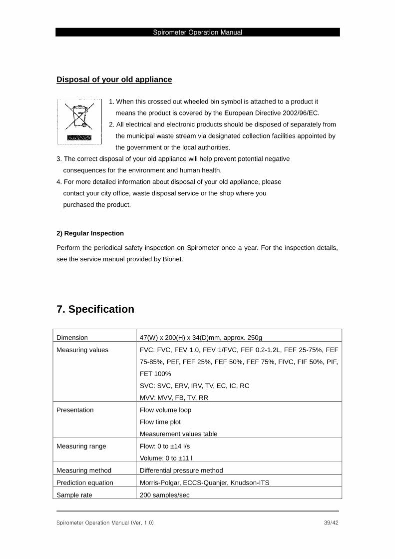
Disposal of your old appliance
1. When this crossed out wheeled bin symbol is attached to a product it
means the product is covered by the European Directive 2002/96/EC.
2. All electrical and electronic products should be disposed of separately from
the municipal waste stream via designated collection facilities appointed by
the government or the local authorities.
3. The correct disposal of your old appliance will help prevent potential negative
consequences for the environment and human health.
4. For more detailed information about disposal of your old appliance, please
contact your city office, waste disposal service or the shop where you
purchased the product.
2) Regular Inspection
Perform the periodical safety inspection on Spirometer once a year. For the inspection details,
see the service manual provided by Bionet.
7. Specification
Dimension 47(W) x 200(H) x 34(D)mm, approx. 250g
Measuring values FVC: FVC, FEV 1.0, FEV 1/FVC, FEF 0.2-1.2L, FEF 25-75%, FEF
75-85%, PEF, FEF 25%, FEF 50%, FEF 75%, FIVC, FIF 50%, PIF,
FET 100%
SVC: SVC, ERV, IRV, TV, EC, IC, RC
MVV: MVV, FB, TV, RR
Presentation Flow volume loop
Flow time plot
Measurement values table
Measuring range Flow: 0 to ±14 l/s
Volume: 0 to ±11 l
Measuring method Differential pressure method
Prediction equation Morris-Polgar, ECCS-Quanjer, Knudson-ITS
Sample rate 200 samples/sec
Spirometer Operation Manual
Spirometer Operation Manual (Ver. 1.0) 40/42
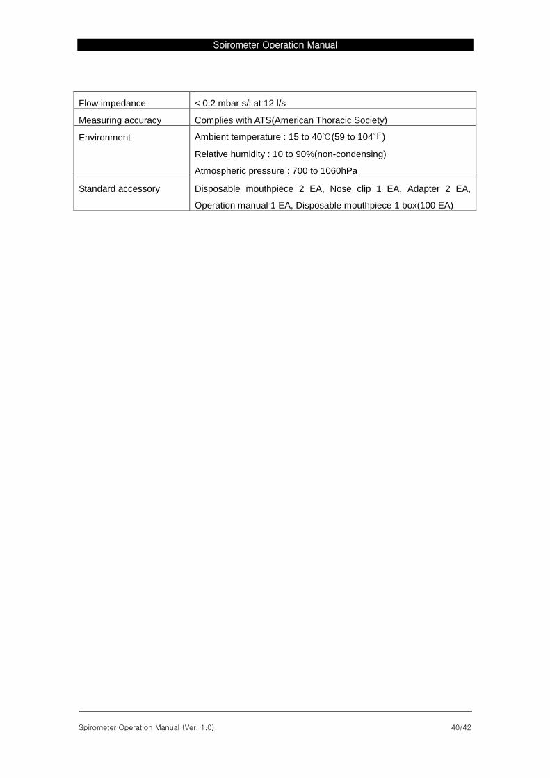
Flow impedance < 0.2 mbar s/l at 12 l/s
Measuring accuracy Complies with ATS(American Thoracic Society)
Environment Ambient temperature : 15 to 40℃(59 to 104℉)
Relative humidity : 10 to 90%(non-condensing)
Atmospheric pressure : 700 to 1060hPa
Standard accessory Disposable mouthpiece 2 EA, Nose clip 1 EA, Adapter 2 EA,
Operation manual 1 EA, Disposable mouthpiece 1 box(100 EA)
Spirometer Operation Manual
Spirometer Operation Manual (Ver. 1.0) 41/42
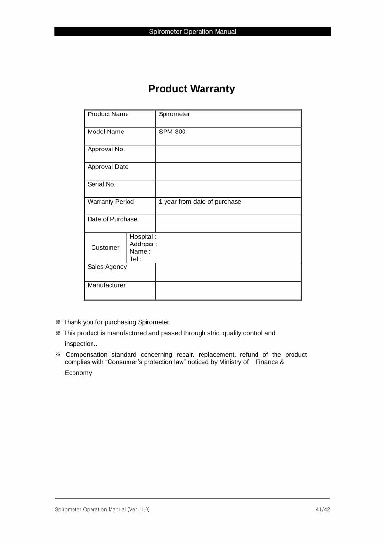
Product Warranty
Product Name Spirometer
Model Name SPM-300
Approval No.
Approval Date
Serial No.
Warranty Period 1 year from date of purchase
Date of Purchase
Customer
Hospital : Address : Name : Tel :
Sales Agency
Manufacturer
※ Thank you for purchasing Spirometer.
※ This product is manufactured and passed through strict quality control and
inspection..
※ Compensation standard concerning repair, replacement, refund of the product
complies with “Consumer’s protection law” noticed by Ministry of Finance &
Economy.

Spirometer Operation Manual
Spirometer Operation Manual (Ver. 1.0) 42/42
International Sales & service Bionet Co., Ltd. :
#11F, E&C DREAM TOWER Ш, 197-33,
Guro-Dong, Guro-Gu, Seoul, South Korea Tel : +82-2-6300-6418 / Fax : +82-2-6499-7789 / e-mail: [email protected]
Website: www.ebionet.com
U.S.A sales & service representative BIONET AMERICA Inc. :
2691, DOW AVENUE SUITE, TUSTIN, CA 92780 U.S.A.
TEL : +1(714)734-1760 / FAX : +1(714)734-1761 / e-mail: [email protected]
Website: www.bionetus.com
European sales & service representative MGB Endoskopische Geräte GmbH Berlin :
Schwarzschildstraße 6
D-12489 Berlin, Germany
Tel. +49(0)306392-7000 / Fax. +49(0)306392-7011 / e-mail: [email protected] Website: www.mgb-berlin.de
Bionet Co.,Ltd Model Name : SPIROMETER