Embed Size (px)
Citation preview
SAL
SPL
8.6” (218 mm) 8.6” (218 mm)
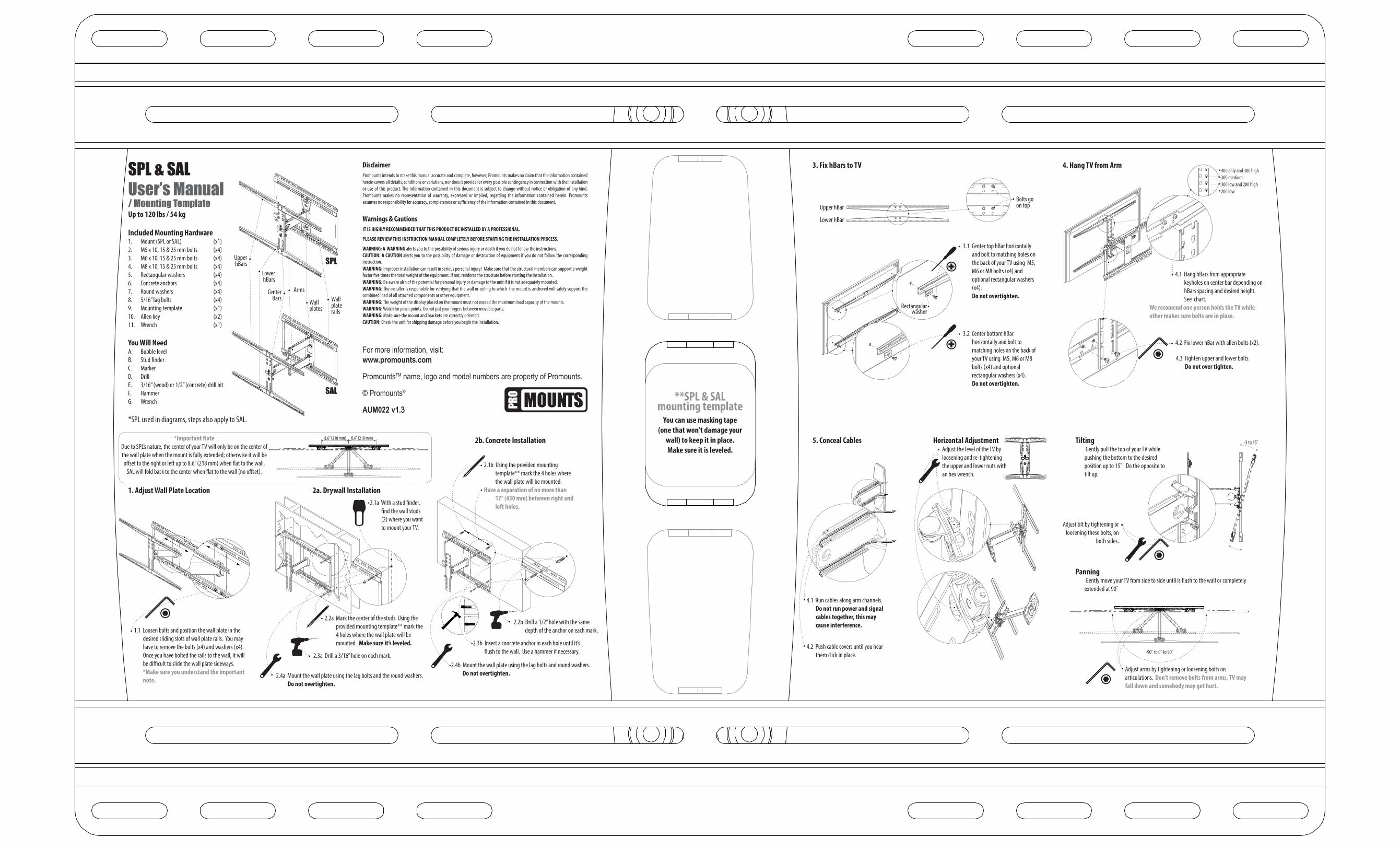
SPL & SALUser’s Manual/ Mounting TemplateUp to 120 lbs / 54 kg
Included Mounting Hardware1. Mount (SPL or SAL) (x1)2. M5 x 10, 15 & 25 mm bolts (x4)3. M6 x 10, 15 & 25 mm bolts (x4)4. M8 x 10, 15 & 25 mm bolts (x4)5. Rectangular washers (x4)6. Concrete anchors (x4)7. Round washers (x4)8. 5/16” lag bolts (x4)9. Mounting template (x1)10. Allen key (x2)11. Wrench (x1)
You Will NeedA. Bubble levelB. Stud �nderC. MarkerD. DrillE. 3/16” (wood) or 1/2” (concrete) drill bitF. HammerG. Wrench
*SPL used in diagrams, steps also apply to SAL.
2.1a With a stud �nder, �nd the wall studs (2) where you want to mount your TV.
2.2a Mark the center of the studs. Using the provided mounting template** mark the 4 holes where the wall plate will be mounted. Make sure it’s leveled.
2.3a Drill a 3/16” hole on each mark.
2.4a Mount the wall plate using the lag bolts and the round washers. Do not overtighten.
2a. Drywall Installation1. Adjust Wall Plate Location
2b. Concrete Installation
3. Fix hBars to TV
Tilting Gently pull the top of your TV while pushing the bottom to the desired position up to 15˚. Do the opposite to tilt up.
Panning Gently move your TV from side to side until is �ush to the wall or completely extended at 90˚
400 only and 300 high300 medium300 low and 200 high200 low
DisclaimerPromounts intends to make this manual accurate and complete, however, Promounts makes no claim that the information contained herein covers all details, conditions or variations, nor does it provide for every possible contingency in connection with the installation or use of this product. The information contained in this document is subject to change without notice or obligation of any kind. Promounts makes no representation of warranty, expressed or implied, regarding the information contained herein. Promounts assumes no responsibility for accuracy, completeness or su�ciency of the information contained in this document.
Warnings & CautionsIT IS HIGHLY RECOMMENDED THAT THIS PRODUCT BE INSTALLED BY A PROFESSIONAL.
PLEASE REVIEW THIS INSTRUCTION MANUAL COMPLETELY BEFORE STARTING THE INSTALLATION PROCESS.
WARNING: A WARNING alerts you to the possibility of serious injury or death if you do not follow the instructions.CAUTION: A CAUTION alerts you to the possibility of damage or destruction of equipment if you do not follow the corresponding instruction. WARNING: Improper installation can result in serious personal injury! Make sure that the structural members can support a weight factor �ve times the total weight of the equipment. If not, reinforce the structure before starting the installation.WARNING: Be aware also of the potential for personal injury or damage to the unit if it is not adequately mounted.WARNING: The installer is responsible for verifying that the wall or ceiling to which the mount is anchored will safely support the combined load of all attached components or other equipment.WARNING: The weight of the display placed on the mount must not exceed the maximum load capacity of the mounts. WARNING: Watch for pinch points. Do not put your �ngers between movable parts.WARNING: Make sure the mount and brackets are correctly oriented.CAUTION: Check the unit for shipping damage before you begin the installation.
For more information, visit:www.promounts.com
PromountsTM name, logo and model numbers are property of Promounts.
© Promounts®
AUM022 v1.3**SPL & SAL
mounting templateYou can use masking tape
(one that won’t damage your wall) to keep it in place.Make sure it is leveled.
4. Hang TV from Arm
Center Bars
Upper hBars
Lower hBars
Arms
Wall plates
Wall plate rails
*Important NoteDue to SPL’s nature, the center of your TV will only be on the center of the wall plate when the mount is fully extended; otherwise it will be o�set to the right or left up to 8.6” (218 mm) when �at to the wall.
SAL will fold back to the center when �at to the wall (no o�set). 2.1b Using the provided mounting
template** mark the 4 holes where the wall plate will be mounted.
Have a separation of no more than 17” (430 mm) between right and left holes.
2.2b Drill a 1/2” hole with the same depth of the anchor on each mark.
2.3b Insert a concrete anchor in each hole until it’s �ush to the wall. Use a hammer if necessary.
2.4b Mount the wall plate using the lag bolts and round washers. Do not overtighten.
4.1 Hang hBars from appropriate keyholes on center bar depending on hBars spacing and desired height. See chart.
We recomend one person holds the TV while other makes sure bolts are in place.
Adjust arms by tightening or loosening bolts on articulations. Don’t remove bolts from arms, TV may fall down and somebody may get hurt.
Rectangular washer
3.1 Center top hBar horizontally and bolt to matching holes on the back of your TV using M5, M6 or M8 bolts (x4) and optional rectangular washers (x4).Do not overtighten.
3.2 Center bottom hBar horizontally and bolt to matching holes on the back of your TV using M5, M6 or M8 bolts (x4) and optional rectangular washers (x4).Do not overtighten.
4.2 Fix lower hBar with allen bolts (x2).
4.3 Tighten upper and lower bolts. Do not over tighten.
Adjust tilt by tightening or loosening these bolts, on
both sides.
Bolts go on top
1.1 Loosen bolts and position the wall plate in the desired sliding slots of wall plate rails. You may have to remove the bolts (x4) and washers (x4). Once you have bolted the rails to the wall, it will be di�cult to slide the wall plate sideways.*Make sure you understand the important note.
Upper hBar
Lower hBar
5. Conceal Cables Horizontal AdjustmentAdjust the level of the TV by loosening and re-tightening the upper and lower nuts with an hex wrench.
4.1 Run cables along arm channels.Do not run power and signal cables together, this may cause interference.
4.2 Push cable covers until you hear them click in place. -90˚ to 0˚ to 90˚
-3 to 15˚
SAL
SPL
8.6” (218 mm) 8.6” (218 mm)
Barra Central
Barra H Inferior
Barra H Superior
Brazo
Placa de pared
Riel
2a. Instalación en Tablaroca
Negación de ResponsabilidadEs la intención de Promounts en hacer de este manual una herramienta informativa completa y precisa. De todas maneras Promounts no puede a�rmar que toda la información en este manual cubre todos los detalles, condiciones o cambios, ni tampoco es aplicable a toda o cualquier eventualidad relacionada con la instalación de este producto. El contenido de este manual puede cambiar sin previo anuncio u obligación de ningún tipo. Promounts no representa la garantía expresa o implícita de la información de este manual. Promounts no asume responsabilidad por la precisión, la información completa o no en este documento.
Advertencias y PrecaucionesES RECOMENDABLE QUE ESTE SOPORTE SEA INSTALADO POR UN PROFESIONAL.
POR FAVOR REVISE ESTE MANUAL Y FAMILIARÍCESE CON TODAS LAS HERRAMIENTAS Y PROCESOS ANTES DE EMPEZAR LA INSTALACIÓN.
ADVERTENCIA: Existe la posibilidad de una herida grave o muerte si no se sigue las instrucciones correctas.PRECAUCIÓN: Existe la posibilidad de la destrucción total o parcial de un equipo si no se sigue las instrucciones correctas. ADVERTENCIA: Una instalación defectuosa puede causar heridas graves. Asegúrese que la pared tenga una capacidad de peso de cinco veces la capacidad total de la TV y soporte juntos. Si la pared no tiene la capacidad de peso requerida por favor refuerce la estructura de la misma.ADVERTENCIA: El instalador tiene la responsabilidad de veri�car que la pared o techo en donde va a ser montada esta unidad tenga la capacidad de peso estimada.ADVERTENCIA: Existe la posibilidad de una herida o daño al equipo si el soporte es instalado de una forma no adecuada. ADVERTENCIA: El peso del TV que va a ser instalado con esta unidad de brazo no puede exceder la capacidad máxima del producto. ADVERTENCIA: Durante la instalación asegúrese de no poner sus dedos en uniones o en lugares donde se pueda lastimar. ADVERTENCIA: Asegúrese que el soporte y todos sus componentes estén correctamente angulados.PRECAUCIÓN: Veri�que que esta unidad no tenga ningún daño que haya podido ser causado durante el transporte de la misma.
Para mayor información, visite:www.promounts.com
El nombre PromountsTM, el logo y los números de modelo son propiedad de Promounts.
© Promounts®
AUM023 v1.3
**SPL y SALplantilla de instalación
Corte en la marca y separe del manual.
Puede usar cinta adhesiva (una que no dañe su pared) para
mantener la plantilla en posición.Asegurese de que este nivelada.
2.1b Con ayuda de la plantilla de instalación** marque los 4 hoyos donde desee montar la placa de pared.
La separación entre los hoyos izquierdos y derechos debe ser menor a 17” (430mm)
2.1a Marque el centro de las vigas. Con ayuda de la plantilla de instalación** marque los 4 hoyos donde desee montar la placa de pared. Asgúrese de que este nivelada.
2b. Instalación en Concreto
2.2b Perfore hoyos de 1/2” con la misma profundidad de las anclas en cada marca.
2.3a Perfore hoyos de 3/16” en cada marca.
2.3b Inserte un ancla de concreto en cada hoyo y empujelo al raz de la pared. Use un martillo si es necesario.
2.4b Monte la placa de pared usando los tornillos hexagonales y las arandelas redondas. No apriete demasiado.2.4a Monte la placa de pared usando los tornillos hexagonales y las
arandelas redondas. No apriete demasiado.
*Nota ImportanteDebido a la naturaleza de SPL, el centro de su TV unicamente estará
alineado al centro de la placa de pared cuando el soporte esta totalmente extendido; de otra manera, habrá una diferencia a la derecha o izquierda
de hasta 8.6” (218 mm) cuando este pegada a la pared.SAM regresará al centro cuando este pegado a la pared (sin diferencia).
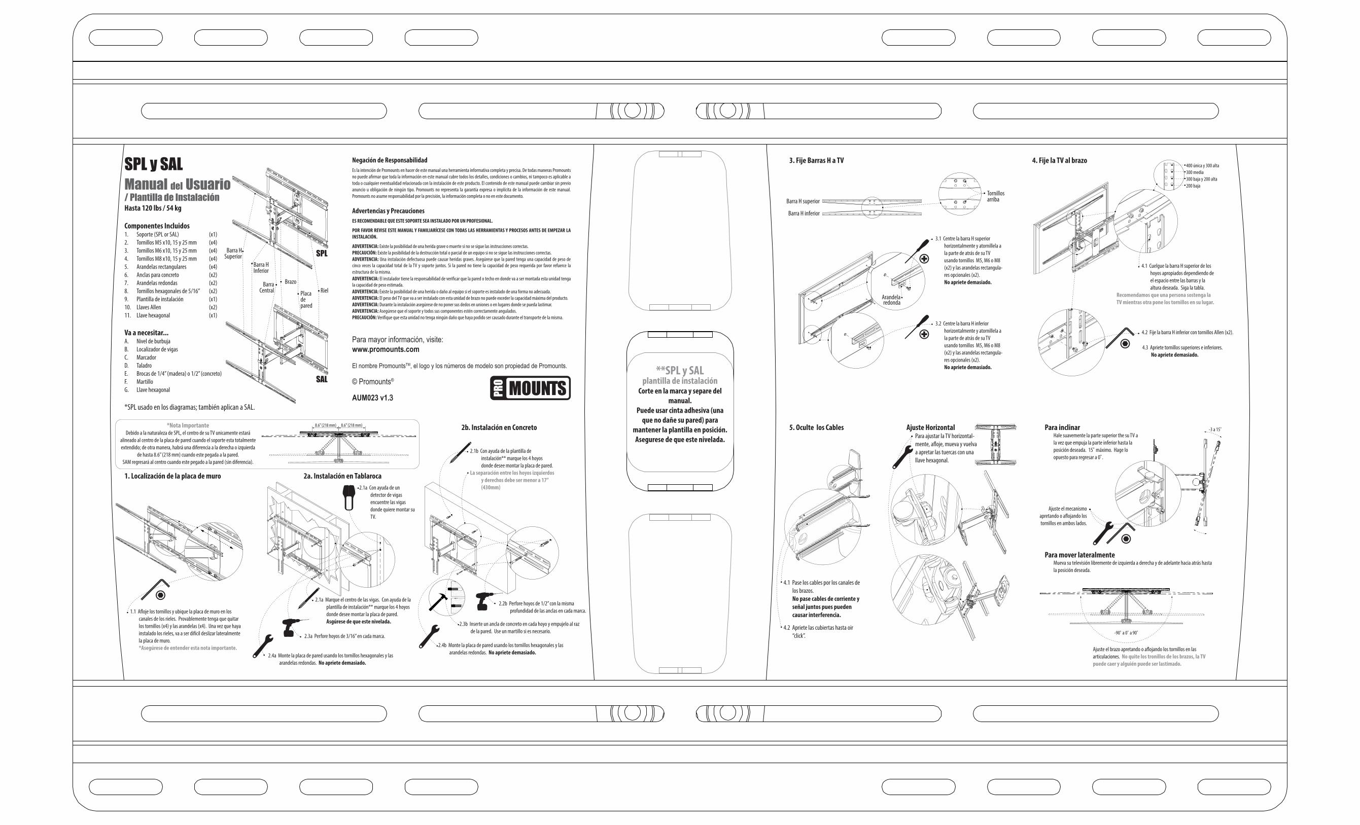
SPL y SALManual del Usuario/ Plantilla de InstalaciónHasta 120 lbs / 54 kg
Componentes Incluidos1. Soporte (SPL or SAL) (x1)2. Tornillos M5 x10, 15 y 25 mm (x4)3. Tornillos M6 x10, 15 y 25 mm (x4)4. Tornillos M8 x10, 15 y 25 mm (x4)5. Arandelas rectangulares (x4)6. Anclas para concreto (x2)7. Arandelas redondas (x2)8. Tornillos hexagonales de 5/16” (x2)9. Plantilla de instalación (x1)10. Llaves Allen (x2)11. Llave hexagonal (x1)
Va a necesitar...A. Nivel de burbujaB. Localizador de vigasC. MarcadorD. TaladroE. Brocas de 1/4” (madera) o 1/2” (concreto)F. MartilloG. Llave hexagonal
*SPL usado en los diagramas; también aplican a SAL.
2.1a Con ayuda de un detector de vigas encuentre las vigas donde quiere montar su TV.
3.1 Centre la barra H superior horizontalmente y atornillela a la parte de atrás de su TV usando tornillos M5, M6 o M8 (x2) y las arandelas rectangula-res opcionales (x2).No apriete demasiado.
3.2 Centre la barra H inferior horizontalmente y atornillela a la parte de atrás de su TV usando tornillos M5, M6 o M8 (x2) y las arandelas rectangula-res opcionales (x2).No apriete demasiado.
3. Fije Barras H a TV
Para inclinarHale suavemente la parte superior the su TV a la vez que empuja la parte inferior hasta la posición deseada. 15˚ máximo. Hage lo opuesto para regresar a 0˚.
Para mover lateralmenteMueva su televisión libremente de izquierda a derecha y de adelante hacia atrás hasta la posición deseada.
4. Fije la TV al brazo400 única y 300 alta300 media300 baja y 200 alta200 baja
1. Localización de la placa de muro
1.1 A�oje los tornillos y ubique la placa de muro en los canales de los rieles. Provablemente tenga que quitar los tornillos (x4) y las arandelas (x4). Una vez que haya instalado los rieles, va a ser difícil deslizar lateralmente la placa de muro.*Asegúrese de entender esta nota importante.
4.1 Cuelgue la barra H superior de los hoyos apropiados dependiendo de el espacio entre las barras y la altura deseada. Siga la tabla.
Recomendamos que una persona sostenga la TV mientras otra pone los tornillos en su lugar.
4.2 Fije la barra H inferior con tornillos Allen (x2).
4.3 Apriete tornillos superiores e inferiores.No apriete demasiado.
Arandela redonda
Tornillos arriba
Ajuste el mecanismo apretando o a�ojando los tornillos en ambos lados.
Ajuste el brazo apretando o a�ojando los tornillos en las articulaciones. No quite los tronillos de los brazos, la TV puede caer y alguién puede ser lastimado.
Barra H superior
Barra H inferior
5. Oculte los Cables
4.1 Pase los cables por los canales de los brazos.No pase cables de corriente y señal juntos pues pueden causar interferencia.
4.2 Apriete las cubiertas hasta oir “click”.
Ajuste HorizontalPara ajustar la TV horizontal-mente, a�oje, mueva y vuelva a apretar las tuercas con una llave hexagonal.
-90˚ a 0˚ a 90˚
-3 a 15˚