Embed Size (px)
DESCRIPTION
technical
Citation preview

2077 Burkett Rd., Rock Hill, S.C. 29730 (803) 325-2341 Fax (803) 329-7755 www.aggressive-equipment.com
AGGRESSIVE EQUIPMENT INC.
PORTABLE PIPE LATHE OPERATIONS & MAINTENACE MANUAL Rev.2
READ AND UNDERSTAND MANUAL BEFORE USING THE SPLIT FRAME
PORTABLE PIPE LATHE
SPLIT FRAME

2
Section 1 • Introduction and Safety
Section 2
• Equipment
Section 3 • Setup
1. Severing Work Piece 2. Counter Boring Work Piece 3. Beveling Work Piece
Section 4
• General Maintenance 1. Split Frame 2. Tool Slide 3. Air Caddy
Section 5
• Parts Break Down

3
Section 1
Introduction and Safety Aggressive Equipment’s split frame is rigid, versatile and operator friendly. Our solid steel frame allows for heavy cutting to achieve a decrease in cutting time. Our machine can be used on thin wall or heavy wall pipe, flanges, 90’s and reducers. All of Aggressive Equipment’s split frames have the following capabilities: sever and bevel with form tooling, bevel with signal point attachment, miter, counter bore, and deep bore turning. After using our equipment, we are sure you will agree it is the best on the market today.
1. You should always use caution when handling equipment! • Equipment can be heavy and awkward to handle. • Personnel may be injured if equipment is not handled safely and properly. • If equipment is too heavy for personnel to maneuver, mechanical means may be
necessary. • When equipment is being handled and in use, personnel must stay away from pinch points
to avoid injury. • Use caution while equipment is cutting. Chips coming off of work piece may be hot and
sharp. • Chips may also cause eye injuries. • Safety glasses must be worn at all times around equipment. • Improper use of split frame can result in equipment failure and injury to personnel.
2. Personnel should always wear personal protection equipment including, but not limited to the following: • Long pants • Long sleeve shirt • Work boots or shoes (leather with steel toe is recommended) • Work gloves (leather) • Safety glasses • Hearing protection

4
Section 2
Equipment
Equipment Break Down and Definitions
A. Frame: The frame is made up of two main parts that split in the middle to attach to any in-line work piece. These two parts are the base ring and the gear ring. The base ring is a stationary ring that is mounted to the work piece. This ring contains the guards, motor housing, trip slot and positioning legs. The gear ring is the half that will rotate to perform the cutting action. This ring contains the bearings, driven gear and tool slide placement slot.
B. Locating Pads: The locating pads are used to attach the base ring to the work piece. They are made in two different configurations. The first is the flat bottom, which is used for mounting to a straight work piece. These come in four sizes: standard, 1”, 2”and 3”. The next configuration is the pointed pad. It is used for setting up on odd shaped work pieces such as 90’s, valves and mitering. These come in four sizes: standard, 1”, 2”and 3”.
C. Tool Slide: The tool slide is used to feed the cutting blades into the work piece. The standard size is a 5” slide. They also come in 3”, 4” and 6” sizes. Your application will determine the size you will need to use. The 3” and 4” slides are generally used for low clearance or thin wall. The 5” slides offer 3” of travel for medium wall cut-offs. The 6” slides are used for heavy wall cut-offs.
D. Counter Bore Attachment: The counter bore attachment is used for prepping the I.D. of a work piece or for doing single point work such as flange facing. This attachment bolts directly onto the tool slide.

5
E. Trip Assembly: The trip assembly is used to engage the star wheel of the tool slide to feed the tool into the work piece. It is bolted onto the back of the base ring at the proper height in relation to the star wheel of the tool slide. This allows for accurate engagement.
F. Motor Mount: The motor mount is used to attach the drive motor. G. Motor: There are three motors that can be used with our split frame.
• Air motor- 100psi / 100cfm of air pressure (right angle, standard duty) (shown in picture)
• Air motor- 100psi / 100cfm of air pressure (in-line, heavy duty) • Hydraulic motor - 8gpm from hydraulic unit (in-line, heavy duty)
H. Air Caddy: The air caddy consist of a filter, pressure gauge and oiler. I. Toolbox: The toolbox contains all of the hand tools required for the set up of a split
frame.

6
Section 3
Setup
1. Horizontal Run (pipe cut-off) Note - The split frame should be inspected to make sure all parts needed are present and free of excess oil before work begins. All guards must be in place before the split frame can be operated. Note - Before placing the split frame on the pipe the correct locating pads should be chosen. Example: If the pipe being cut is 20” O.D. and the machine being used is a SF2014 (this machine has a 21” I.D.), the correct locating pad is the standard pad (S). If the same machine were to be used on an 18” O.D. pipe, the proper locating pad would be the 1” pad (1).
Split Frame Sizes Pipe Size
(O.D.) 4 6 8 10 12 14 16 18 20 22 24 26 28 30 32 34 36
2.375” 1 2
2.875” S 2
3.5” S 2 3
4” S 1 2
4.5” S 1 2
5.563” 1 1 3
6.625” S 1 2 3
8.625” S 1 2 3
10.75” S 1 2 3
12.75” S 1 2 3
14” S 1 2 3
16” S 1 2 3
18” S 1 2 3
20” S 1 2 3
22” S 1 2 3
24” S 1 2 3
26” S 1 2 3
28” S 1 2 3
30” S – Standard Length Locating Pad S 1 2 3
32” 1 – 1” Length Locating Pad S 1 2
34” 2 – 2” Length Locating Pad S 1
36” 3 – 3” Length Locating Pad (special order, not recommended on heavy wall pipe) S

7
Split Frame Sizes Pipe
Size (O.D.) 38 40 42 44 46 48 50 52 62 70 80
32” 3
34” 2 3
36” 1 2 3
38” S 1 2 3
40” S 1 2 3
42” S 1 2 3
44” S 1 2 3
46” S 1 2 3
48” S 1 2
50” S 1
52” S
54”
56” 3
58” 2
60” 1 S
62” S S
64” S
66” S
68” S
70” S S
72” S
74” S – Standard Length Locating Pad S
76” 1 – 1” Length Locating Pad S
78” 2 – 2” Length Locating Pad S
80” 3 – 3” Length Locating Pad (special order, not recommended on heavy wall pipe) S
1. Remove the split frame from the storage container. 2. Inspect the split frame to insure that all guards are in place and properly secured. Each
split frame has orange sheet metal guards over the gear teeth of the gear ring and a housing cover over the drive gear.
3. Excessive oil should be removed from the equipment before each use. 4. The split frame must have the correct locating pads on the legs for each job. To change
locating pads, simply turn the leg bolt to the right (clockwise) with a 5/16” hex wrench until the locating pad is exposed. Pull the locating pad towards the I.D. of the split frame to remove. Select the proper locating pads for the job and place them onto the legs.

8
5. Place the top half of the split frame (half with the motor mount) on top of the work piece. The gear ring should be facing cut line.
6. Lift the bottom half of the split frame up to match the top half. Once in place, the swing bolts on the bottom half of base ring should be latched to the top half and tightened. The gear ring also has two bolts at the split that must be tightened.
7. Pull the shipping pins out of the gear ring (x2). There will be one pin per half. Once the pins are removed from the split frame the gear ring will be able to rotate.

9
8. The tool slides should be bolted onto the split frame. The slides are fastened to the split frame using 5/16”-18 x 5/8” SHCS provided in the toolbox. The tool holder may be set at various heights, but both slides must be set at the same height on split frame. If they are not set to the same height the trip assembly will not be able to engage with both slides properly. Insert a 1/4” cut-off blade into one slide. Use the cut-off blade to roughly set the split frame to the cut line. The leg bolts should be tightened to the pipe to maintain position. While the leg bolts are being tightened, roughly square and center the split frame.
9. Once the split frame is positioned to the cut line, final squaring and centering must be done. The leg bolts are positioned 90° apart so that the equipment can be properly aligned to the work piece. To align the split frame to the work piece, opposing legs are used to work together. In our set up, the motor mount is at 0° or top dead center and the leg bolts are at 45°, 135°, 225° and 315° from 0°. The leg bolts at 45° and 225° we will call group “A” and the leg bolts at 135° and 315° we will call group “B”. To square and center the split frame to the work piece, make sure that group “A” leg bolts are snug. Loosen group “B” so that the split frame can be rotated along the axis of the work piece. Use the machinist square provided in the toolbox to insure that the split frame is square to the work piece. This must be checked at the locating pad area. Both sides of group “B” must be checked. Snug the leg bolts in group “B” to maintain your position. Measure the distance at group “A” locating pads from the O.D. of pipe to the I.D. of the split frame. Adjust group “A” leg bolts to even measurements on each side. Once group “A” is centered, tighten the leg bolts in group “B”. Repeat this process with opposite legs until the split frame is square and centered.

10
10. Make sure all of the leg bolts are tight before any steps are continued. If the leg bolts are not tight, the split frame may move during cutting.
11. Set cut-off blades. • The tool holder of the slide should be raised to its highest point. Tool holder of the
slide is raised by rotating the 9/16” hex on the front side of the gearbox at the top of the slide. A speed wrench and 9/16” socket are provided in the toolbox.
• A 3/16” cut-off blade should be placed into one tool holder. Allow the 3/16” sever blade to touch the work piece. Snug the bolts in the tool holder cover plate to hold the blade in place. Rotate the gear ring by hand CCW around the work piece. This will set the cut-off blade to the highest point that it needs to be. Tighten the bolts in the cover plate to hold the blade firmly.
Caution - When rotating the gear ring, avoid placing hands and fingers in pinch points. • Insert a 1/4” cut-off blade into the opposite tool holder 1/8” - 3/16” further from the
work piece than the 3/16” cut-off blade. Tighten the bolts in the cover plate. 12. Set the trip assembly to the correct height so that the slides and trip assembly work together
properly. The trip assembly is attached with a 3/8” shoulder bolt that is provided in the toolbox. • The gear ring should be rotated to check each tool slide’s star wheel alignment
with the trip assembly. Caution - When rotating the gear ring, avoid placing hands and fingers in pinch points.

11
13. To install the motor, insert the motor shaft into the opening of the motor mount housing. Set the motor at the desired angle and tighten the two motor mount screws into the housing. The motor mount screws are provided in the toolbox.
14. Connect the air whip to the motor and air caddy. Extensions can be placed between the air whip and air caddy if the air caddy cannot be located within 10’ of work area. Extension must not exceed 50’ in length. The air whip must be attached to the discharge side of the air caddy. The air supply must be attached to the supply side. Note- Before connecting the air supply to the air caddy, make sure motor hand lever is not engaged. This could cause the SF to rotate unexpectedly, which could injure personnel. • The oil level of the air caddy should be checked before the air supply is attached.
Supply Side →
→ Discharge Side
15. Engage the trip assembly. The trip assembly is engaged by rotating the handle to the up position. The trip should be engaged before the motor is started.
16. Start the air motor by squeezing the hand lever on the motor. Note - Rotating equipment can cause injury to personnel.
12
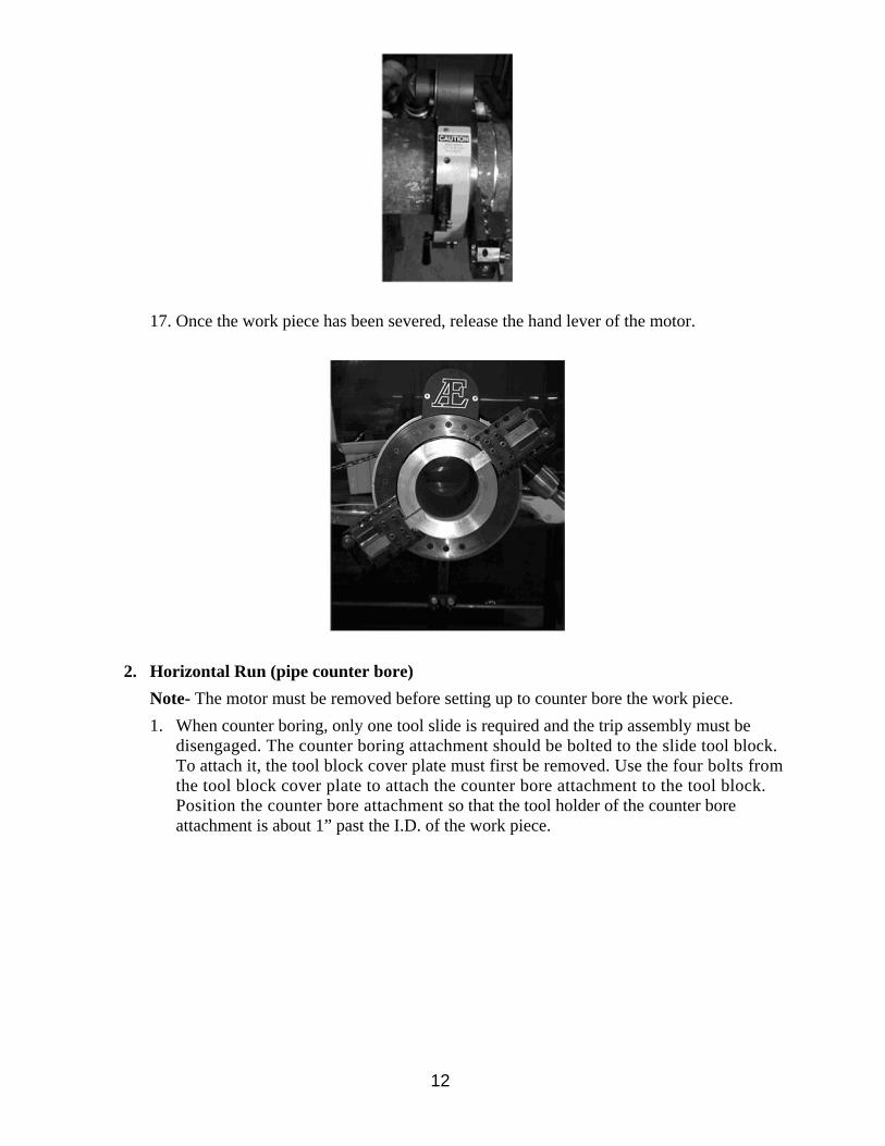
17. Once the work piece has been severed, release the hand lever of the motor.
2. Horizontal Run (pipe counter bore) Note- The motor must be removed before setting up to counter bore the work piece. 1. When counter boring, only one tool slide is required and the trip assembly must be
disengaged. The counter boring attachment should be bolted to the slide tool block. To attach it, the tool block cover plate must first be removed. Use the four bolts from the tool block cover plate to attach the counter bore attachment to the tool block. Position the counter bore attachment so that the tool holder of the counter bore attachment is about 1” past the I.D. of the work piece.

13
2. The split frame should be aligned to the I.D. of the work piece so that the counter bore prep is even. Centering Split Frame to the I.D. • Insert the counter bore tool into the counter bore tool holder (cutting edge toward
work piece). The counter bore tool must protrude out far enough to allow all of the cutting edge and relief angle to be exposed. Tighten the cover plate to hold the tool.
• Use the hand wheel on the back of the counter bore attachment to feed the tool inside the work piece to about ~”. The tool must not touch the I.D. of the work piece during set up. If the tool is touching the I.D. of the work piece, rotate the 9/16” hex on the tool slide gearbox counter clockwise to feed the tool slide tool block towards the work piece.
• Center the split frame to the I.D. of the pipe by adjusting the leg bolts. Measure from the counter bore tool to the I.D. of the pipe. The tool slide should be in line with one of the legs of the split frame when the measurement is taken. Opposing legs of the split frame are used to center the split frame from side to side.
3. Next, bring the counter bore tool to the work piece by rotating 9/16” hex on the tool slide gearbox clockwise. The I.D. of the work piece maybe out of round. The counter bore tool should be touched off at the smallest I.D. dimension.
4. Rotate the hand wheel of the counter bore attachment clockwise to retract the tool from the work piece.
5. To increase the cut of the tool in the counter bore attachment, rotate the tool slide star wheel clockwise. Each revolution of the star wheel will move the tool block .008”.
6. Install the motor onto the split frame. 7. Turn the motor on. 8. As the split frame rotates, feed the counter bore tool into the work piece by turning the
hand wheel counter clockwise. Feed the tool to the desired depth. Then retract the tool by turning the hand wheel clockwise.
9. Repeat steps 5 and 8 until the I.D. measurement is to the desired size. 10. Remove the counter bore attachment when the counter bore is complete.

14
3. Horizontal Run (pipe beveling) • Note – The motor must be removed before setting up to bevel the work piece. • Note - If counter boring was not done, refer to Part 2, steps 1 and 2 to center the split
frame to the I.D. of the work piece. Centering the split frame to the I.D. of the work piece will produce a more even land when the beveling process is complete.
1. Only one tool slide is required when beveling. Raise the tool slide tool block if it is not in the up position.
2. In our set up, the bevel that will be cut is a 37°/10° compound bevel. 3. Attach the cover plate to the tool block so that the bevel tool can be locked into place.
Insert the bevel tool into the 1/2” slot in the tool block. Tighten the bolts to lock the bevel tool in place. The standard bevel tool will bevel up to 1 ~” wall thickness. Set the bevel tool so that all of cutting surface of tool is outside of the tool block towards the work piece. The bevel tool should not be touching the work piece.
4. Engage the trip assembly. If the tool slide has been moved since the severing process, it must be checked for proper alignment with the trip assembly.
5. Attach the motor to the motor mount. 6. Start the motor. 7. Once the beveling process is complete, turn off the motor.
8. Remove the split frame from the work piece and clean. Equipment should be returned to the shipping container or staged for the next job.

15
Section 4
General Maintenance
1. Split Frame The split frame body consists of many parts; all of which are important to the over all performance of the split frame. The equipment will have a premature life span and decreased performance if it is not maintained properly. 1. The split frame has four main body parts: two base ring halves and two gear ring halves.
2. The base ring has three major parts: the “V” groove, motor mount and leg assemblies. • The “V” groove is where the “V” bearings on the gear ring ride. The gear ring
should be removed from the base ring after each use to remove any chips that may collect inside the split frame. Chips in the split frame can scar the “V” groove and damage the riding surface of the “V” bearings. Apply a light film of oil to the “V” groove.
• The leg assemblies should be operated and cleaned of any chips. If the legs become scarred, it can cause the legs to be hard to move and reduce the rigidity of the split frame. A light film of oil should be applied to the leg assemblies.

16
• The motor mount may also collect chips. It is important to remove the housing cover and remove any chips from around the gear. Chips lodged in the gears may cause damage to the gear teeth.
3. The gear ring has 2 major areas that must be checked, the gear and the bearings. • The gear of the gear ring is very important to the operation of the split frame. It is
imperative that the gear be properly cleaned of chips and inspected for wear or damage. After cleaning and inspection, a light coat of oil should be applied.

17
• The split frame bearings are “V” shaped. This allows the bearing to properly ride on the ground “V” groove of the base. Bearings must be cleaned and inspected for wear and damage during cleaning of the machine. The bearings that are used in our split frames are sealed and do not require any greasing. If the bearings appear worn or the seals damaged, then the bearings should be replaced.
2. Tool Slides The tool slide is composed of 3 major parts: the slide base, the tool holder and the gearbox.
1. Slide Base - The slide base is used to attach the slide assembly to the split frame. It is also used as a guide system for the tool holder. It is important to clean the slide base of any chips after each use. Chips may scar the slide base wear surfaces. This will cause the tool holder to have difficulty traveling down the slide base.

18
2. Tool Holder - The tool holder is used to hold the cutting tool in position during the cutting process. It should be cleaned of any chips after each tool change and before it is placed back into the storage container.
3. Gearbox - The gearbox is comprised of 7 main parts: gearbox, lead screw, star wheel cap nut, star wheel trip cam, spur gear, bronze washer and (2) needle trust bearing assemblies. All of these parts must work together for the gearbox to feed the tool holder properly.
A. Gearbox - The gearbox houses all of the other parts listed above. B. Lead Screw - This part feeds the tool holder up and down the slide base. C. Star Wheel Cap Nut - The star wheel cap nut is used to retain the star wheel in
the gearbox. D. Star Wheel Trip Cam - This part serves a dual purpose. It engages with the trip
assembly and rotates the spur gear. The star wheel portion should be checked for wear and tightness.
E. Spur Gear - The spur gear is connected to the lead screw and engages with the star wheel trip cam. It should be inspected for wear. Make sure that the nylock nut that holds it to the lead screw is tight.
F. Needle Trust Bearing Assembly - These are located on top and bottom of the gearbox. One is between the cap nut and gearbox and the other is between the gearbox and star wheel. They should be inspected and greased every 100 hours of use or if they have been exposed to a harsh environment. Each bearing is enclosed between two hardened washers.
G. Bronze Washer - This part is between the lead screw and the gearbox. Its purpose is to provide a replaceable area of wear between the lead screw and the gearbox. It should be measured to inspect the amount of wear and should be replaced if it measures below .100” thick.
19
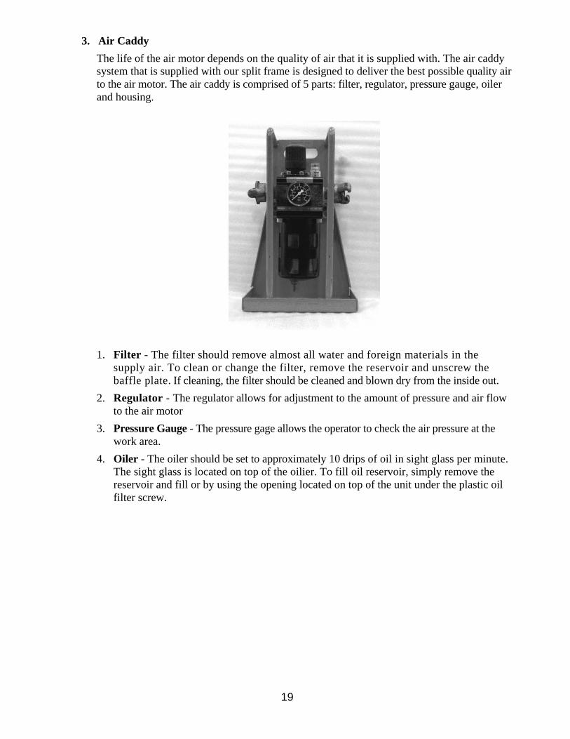
3. Air Caddy The life of the air motor depends on the quality of air that it is supplied with. The air caddy system that is supplied with our split frame is designed to deliver the best possible quality air to the air motor. The air caddy is comprised of 5 parts: filter, regulator, pressure gauge, oiler and housing.
1. Filter - The filter should remove almost all water and foreign materials in the supply air. To clean or change the filter, remove the reservoir and unscrew the baffle plate. If cleaning, the filter should be cleaned and blown dry from the inside out.
2. Regulator - The regulator allows for adjustment to the amount of pressure and air flow to the air motor
3. Pressure Gauge - The pressure gage allows the operator to check the air pressure at the work area.
4. Oiler - The oiler should be set to approximately 10 drips of oil in sight glass per minute. The sight glass is located on top of the oilier. To fill oil reservoir, simply remove the reservoir and fill or by using the opening located on top of the unit under the plastic oil filter screw.

20
4” – 24” Split Frame Assembly

21
4” – 24” Split Frame Assembly Item Part Number Qty. Description
1 FHSCS1/4-20x1-1/2 2 1/4-20 x 1-1/2” FHSCS
2 SF-0002 1 Gear Retaining Ring
3 SF-0003 4 3/8-16 Threaded Insert
4 SHCS3/8-16x1 2 3/8-16 x 1” SHCS
SF-0019 # Eccentric Bearing Pin Nut (4” Split Frame) 5
SF-0010 # Eccentric Bearing Pin Nut (6” – 24” Split Frame)
6 BP-0003 # .050” Bearing Shim
EP-04-01 # Eccentric Bearing Pin (4” Split Frame) 7
EBS-0001 # Eccentric Bearing Pin (6” – 24” Split Frame)
8 DowelPin-AS3/8Dx1L 4 3/8” x 1” Dowel Pin
9 SHCS3/8-16x1-1/4 2 3/8-16 x 1-1/4" SHCS
10 SH-0002 2 Gear Hinge Nut
11 SHCS3/8-16x2-1/2 2 3/8-16 x 2-1/2" SHCS
12 SHCS3/8-16x2 2 3/8-16 x 2" SHCS
13 SH-0003 2 Base Hinge Nut
14 SH-0001 2 3/4" Swing Hinge
15 SF-0013 2 Shipping Pin
SF-0018 # V-Groove Bearing (4” Split Frame) 16
SF-0012 # V-Groove Bearing (6” – 24” Split Frame)
17 ** 1 Gearbox Cover (See Chart)
GR-0001 1 3" Drive Gear (Pneumatic) 18
GR-0003 1 3" Drive Gear (Hydraulic)
19 SF-0014 2 Drive Gear Bearing
20 ** 1 Gearbox (See Chart)

22
**Note: These parts are not interchangeable. Use part numbers as follows:
Split Frame Part Number Description
GC-0004 Gearbox Cover 4”
GB-0004 Gearbox
GC-0006 Gearbox Cover 6”
GB-0006 Gearbox
GC-0008 Gearbox Cover 8”
GB-0008 Gearbox
GC-0010 Gearbox Cover 10”
GB-0010 Gearbox
GC-0012 Gearbox Cover 12”
GB-0012 Gearbox
GC-0014 Gearbox Cover 14”
GB-0014 Gearbox
GC-0016 Gearbox Cover 16”
GB-0016 Gearbox
GC-0018 Gearbox Cover 18”
GB-0018 Gearbox
GC-0020 Gearbox Cover 20”
GB-0020 Gearbox
GC-0022 Gearbox Cover 22”
GB-0022 Gearbox
GC-0024 Gearbox Cover 24”
GB-0024 Gearbox

23
26” – 62” Split Frame Assembly

24
26” – 62” Split Frame Assembly Item Part Number Qty. Description
1 FHSCS1/4-20x1-1/2 2 1/4-20 x 1-1/2” FHSCS
2 SF-0002 1 Gear Retaining Ring
3 SF-0003 4 3/8-16 Threaded Insert
4 SHCS3/8-16x1 2 3/8-16 x 1” SHCS
5 SF-0010 # Eccentric Bearing Pin Nut
6 BP-0003 # .050” Bearing Shim
7 EBS-0001 # Eccentric Bearing Pin
8 DowelPin-AS1/2Dx1L 4 1/2" x 1" Dowel Pin
9 SHCS1/2-13x2-1/2 2 1/2-13 x 2-1/2" SHCS
10 SH-0005 2 Gear Hinge Nut
11 SHCS3/8-16x2-1/2 2 3/8-16 x 2-1/2" SHCS
12 SHCS1/2-13x2-1/4 2 1/2-13 x 2-1/4" SHCS
13 SH-0004 2 Base Hinge Nut
14 SH-0006 2 1" Swing Hinge
15 SF-0013 2 Shipping Pin
16 SF-0012 # V-Groove Bearing
17 ** 1 Gearbox Cover (See Chart Below)
GR-0002 1 3.7" Drive Gear (Pneumatic) 18
GR-0004 1 3.7" Drive Gear (Hydraulic)
19 SF-0014 2 Drive Gear Bearing
20 ** 1 Gearbox (See Chart Below)

25
**Note: These parts are not interchangeable. Use part numbers as follows:
Split Frame Part Number Description
GC-0026 Gearbox Cover 26”
GB-0026 Gearbox
GC-0028 Gearbox Cover 28”
GB-0028 Gearbox
GC-0030 Gearbox Cover 30”
GB-0030 Gearbox
GC-0032 Gearbox Cover 32”
GB-0032 Gearbox
GC-0034 Gearbox Cover 34”
GB-0034 Gearbox
GC-0036 Gearbox Cover 36”
GB-0036 Gearbox
GC-0038 Gearbox Cover 38”
GB-0038 Gearbox
GC-0040 Gearbox Cover 40”
GB-0040 Gearbox
GC-0042 Gearbox Cover 42”
GB-0042 Gearbox
GC-0044 Gearbox Cover 44”
GB-0044 Gearbox
GC-0046 Gearbox Cover 46”
GB-0046 Gearbox
GC-0048 Gearbox Cover 48”
GB-0048 Gearbox
GC-0050 Gearbox Cover 50”
GB-0050 Gearbox
GC-0052 Gearbox Cover 52”
GB-0052 Gearbox
GC-0062 Gearbox Cover 62”
GB-0062 Gearbox

26
Leg Assembly

27
Leg Assembly Item Part Number Qty. Description
1 LB-0001 1 Leg Bolt
2 LB-0002 1 Leg Retainer Plate
3 LB-0003 1 Leg Support
4 LB-0004 1 Standard Foot Pad
5 LB-0005 1 1” Foot Pad
6 LB-0006 1 2” Foot Pad
7 LB-0007 1 Standard Pointed Foot
8 LB-0008 1 1” Pointed Foot
9 LB-0009 1 2” Pointed Foot
10 LB-0010 1 3” Foot Pad
11 LB-0011 1 1/4" Key
12 LB-0012 1 Retainer Clip
13 LB-0013 1 Magnet
14 LB-0014 1 3” Pointed Foot
15 SHCS1/4-20x1/2 4 1/4-20 X 1/2" SHCS
16 LB-0016 1 Brass Washer

28
Tool Slide Assembly

29
Tool Slide Assembly Item Part Number Qty. Description
1 TS-0001 1 Gear Box
TS-0023 1 3" Slide Base
TS-0020 1 4" Slide Base
TS-0002 1 5" Slide Base 2
TS-0019 1 6" Slide Base
3 TS-0003 1 Star Wheel Trip Cam
4 TS-0004 1 Slider Nut
TS-0038 1 3” Lead Screw
TS-0039 1 4” Lead Screw
TS-0005 1 5” Lead Screw 5
TS-0037 1 6” Lead Screw
6 TS-0021 1 Tool Holder
7 TS-0007 1 Tool Holder Cover
8 TS-0008 1 Star Wheel Cap Nut
9 TS-0009 1 Spur Gear
10 TS-0017 1 Plastic Cap
11 NylockNut5/16-18 1 5/16-18 Nylock Nut
12 FlatWasher5/16x5/8 1 5/16” I.D. x 5/8” O.D. Flat Washer
13 SHCS1/4-20x7/8 3 1/4-20 x 7/8” SHCS
14 SetScrew-CP3/8-16x1/2 1 3/8-16 x 1/2” Set Screw
15 TS-0029 4 3/4" Needle Thrust Bearing Washer
16 TS-0030 2 3/4" Needle Thrust Bearing
17 SetScrew-CP10-32x1-1/4 # 10-32 x 1-1/4" Set Screw
18 HexNut10-32 # 10-32 Hex Nut
19 TS-0033 1 3/8" I.D. x 3/4" O.D. Bronze Washer
TS-0040 1 3” Tool Slide Gib
TS-0041 1 4” Tool Slide Gib
TS-0034 1 5” Tool Slide Gib 20
TS-0042 1 6” Tool Slide Gib
21 SHCS5/16-18x5/8 4 5/16-18 x 5/8" SHCS
22 SHCS5/16-18x7/8 2 5/16-18 x 7/8" SHCS

30
Trip Assembly

31
Trip Assembly Item Part Number Qty. Description
ST-0013 1 4” Trip Arm
ST-0001 1 5” Trip Arm 1
ST-0014 1 6” Trip Arm
2 ST-0002 1 Trip Head
3 ST-0003 1 Trip Face Plate
4 ST-0004 1 Pull Pin
5 ST-0005 1 Swing Cam
6 ST-0006 1 Spring
7 DowelPin-SS5/8Dx2-1/2L 2 Dowel Pin
8 ST-0008 1 Plastic Handle
9 SHCS1/4-20x3/8 2 1/4-20 x 3/8” SHCS
10 SHCS1/4-20x5/8 2 1/4-20 x 5/8” SHCS
11 SHCS10-32x3/4 1 10-32 x 3/4” SHCS
12 SHCS1/4-20x3/4 1 1/4-20 x 3/4” SHCS

32
Counter Bore Attachment Assembly

33
Counter Bore Attachment Assembly Item Part Number Qty. Description
1 CB-0001 1 Base Plate
2 CB-0002 1 Slide Plate
3 CB-0003 1 Tool Holder
4 CB-0004 1 Tool Holder Cover
5 CB-0005 1 Pressure Plate
6 CB-0006 1 Handle
7 TS-0004 1 Slider Nut
8 TS-0039 1 4” Lead Screw
9 TS-0041 1 4" Tool Slide Gib
10 CB-0012 1 Gusset Block
11 FHSCS1/4-20x3/4 8 1/4-20 x 3/4" FHSCS
12 SHCS5/16-18x3/4 2 5/16-18 x 3/4” SHCS
13 SHCS10-32x7/8 4 10-32 x 7/8" SHCS
14 HexNut10-32 4 10-32 Hex Nut
15 NylockNut5/16-18 1 5/16-18 Nylock Nut
16 SHCS10-32x5/8 4 10-32 x 5/8" SHCS
17 TS-0033 1 3/8" I.D. x 3/4" O.D. Bronze Washer
18 CB-0021 1 3/8" Needle Thrust Bearing
19 CB-0022 2 3/8" Needle Thrust Bearing Washer