Embed Size (px)
Citation preview
Efficiency Maine Team IV Subcooling a Fujitsu 15RLS2 Mini-Split Heat Pump
Appendix G: MEE 443 Experiment Report
May 8, 2014
Submitted to:
Michael L. Peterson, Ph.D. “In partial fulfillment of requirements for MEE 488, Spring 2014”
CC:
Murray Callaway, M.A. “In partial fulfillment of requirements for ECP 488, Spring 2014”
Submitted by:
Samuel M. Prentiss, Matt D. H. Strong, Bruce L. Tuttle
Mechanical Engineering Department
College of Engineering University of Maine 5711 Boardman Hall
Orono, ME 04469-5711
Efficiency Maine Team IV: Subcooling Mini-Split Heat Pump
MEE 443 Mechanical Lab III Experiment Proposal
Samuel M. Prentiss Matt D. H. Strong
Bruce L. Tuttle
MEE 487 Senior Design Capstone
University of Maine Department of Engineering 5711 Boardman Hall
Orono, ME 04469-5711 May 7th, 2014

ii
Table of Contents 1 Introduction .......................................................................................................................................... 1
1.1 Capstone Project Background ....................................................................................................... 1
1.2 Subcooler Unit Mechanical Componentry .................................................................................... 3
2 Proposed Experiment ............................................................................................................................ 6
3 Objectives: ............................................................................................................................................ 7
4 Apparatus, Equipment, Instrumentation .............................................................................................. 8
4.1 Apparatus .................................................................................................................................... 10
4.2 Equipment and Instrumentation ................................................................................................ 11
5 Theory ................................................................................................................................................. 12
5.1.1 Calculating Heat of Rejection from Subcooler Unit ............................................................ 12
5.1.2 Calculating Subcooler Unit Efficiency ................................................................................. 15
6 Kline and McClintock Uncertainty Analysis: ....................................................................................... 16
7 Plan of Work: ...................................................................................................................................... 20
8 Procedure: ........................................................................................................................................... 21
8.1 Measuring Airstream Velocity Profile: ........................................................................................ 21
8.1.1 Measuring Subcooler Unit Airstream Inlet and Outlet Temperatures ............................... 23
8.1.2 Measuring Subcooler Unit Refrigerant Inlet and Outlet Temperatures ............................. 24
8.1.3 Measuring Subcooler Unit Input Power .............................................................................. 26
9 Expected Results: ................................................................................................................................ 27
10 Results ............................................................................................................................................. 28
10.1 Subcooler Unit Airstream Velocity Profile .................................................................................. 28
10.2 Subcooler Unit Heat Output ....................................................................................................... 28
10.3 Subcooler Unit Operating Efficiency ........................................................................................... 30
11 Conclusions ..................................................................................................................................... 31

1
1 Introduction
1.1 Capstone Project Background At the beginning of the 2013-2014 academic school year, five capstone groups comprised of seniors majoring in
Mechanical Engineering at the University of Maine were tasked to evaluate the cost effectiveness of Efficiency Maine’s
electricity energy usage programs.
Efficiency Maine is a quasi-public independent trust committed to reducing the energy usage in the State of Maine. A
significant portion of the funding for Efficiency Maine comes from the System Benefit Charge (SBC) and the Regional
Greenhouse Gas Initiative (RGGI). SBC money comes from an additional charge applied to customers on their monthly
electrical bill and RGGI money comes from carbon allowances purchased by electricity production plants. Due to these
two chief sources of funding sources, the primary focus of the trust has been on reducing electricity usage in Maine. To
the informed individual this is an ironical goal since electricity usage in Maine is unusually low. Furthermore, legislation
has been underway to expand Maine’s electric grid!
Several of Efficiency Maine programs and proposed savings to residents and reduction in greenhouse gas emissions have
fallen short of their mark. This combined with the increased costs of electricity in Maine led to the formation of the five
capstone projects. It was desired that each group perform an unbiased analysis free of bureaucratic policy constraints.
This analysis could take the form of a transportable demo unit or a system installation at a public building, which would
both help educate the public on the more obscure technical aspects of available energy products.
Our capstone group, Efficiency Maine Team IV, sought to design and fabricate a miniature air handling device to increase
the efficiency of a residential air-to-air mini-split heat pump (MSHP). This device, to be incorporated into the MSHP, has
been deemed the Subcooler Unit. In addition to testing and validating the subcooling concept, a thorough economic
analysis has also been completed evaluating the cost effectiveness of Efficiency Maine Team IV’s project associated with
MSHPs.
The concept of subcooling a Fujitsu 15RLS2 MSHP to increase the COP derives from the theory that when a stock Fujitsu
15RLS2 MSHP is running in heating mode there is typically unused thermal energy in the liquid refrigerant after it
condenses and exits the indoor unit’s heat exchanger coil. The Subcooler Unit has been designed to extract this unused
heat from the liquid refrigerant and transfer it to a flowing airstream by means of a refrigerant-to-air coil heat exchanger
and a centrifugal fan. Theoretically, the refrigerant should enter and exit the Subcooler Unit as a liquid. To effectively
transfer thermal energy from the liquid refrigerant to the airstream, an aluminum micro-channel coil produced by Alcoil
has been selected because of its small physical size and high rated capacity for heat transfer.
Since the R-410A refrigerant flowing through the heat exchanger in the Subcooler Unit remains a liquid, all heat transfer
from the R-410A refrigerant to the airstream is considered sensible heat and the process of the liquid refrigerant
decreasing in temperature is subcooling. All phase change from a vapor to a liquid (condensing) has already occurred
within the Fujitsu 15RLS2’s indoor unit.
To incorporate the Subcooler Unit into the heat pump cycle of the Fujitsu 15RLS2, the liquid copper refrigerant line
exiting the Fujitsu 15RLS2’s indoor unit is diverted and connected to the upper (inlet) connection on the micro-channel
coil located in the Subcooler Unit. The lower (outlet) connection on the micro-channel coil in the Subcooler Unit
2
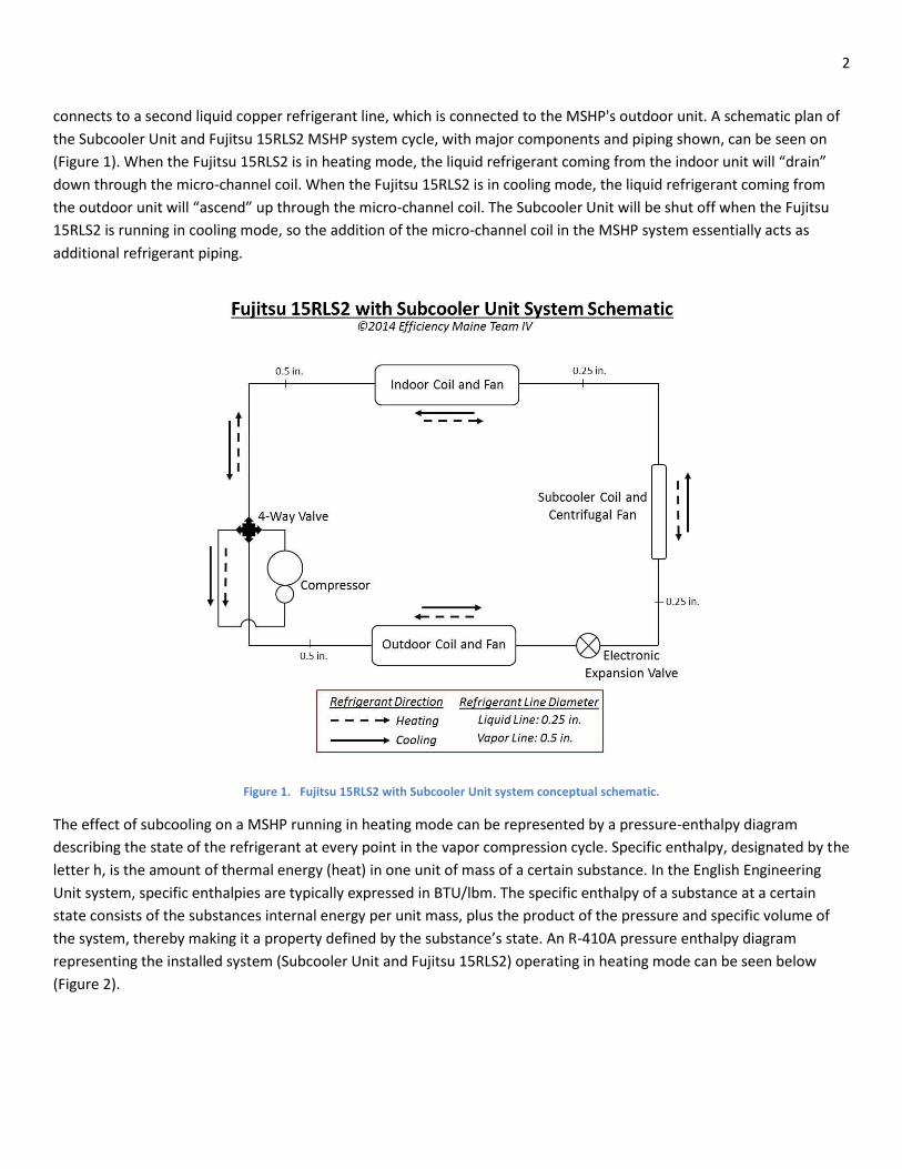
connects to a second liquid copper refrigerant line, which is connected to the MSHP's outdoor unit. A schematic plan of
the Subcooler Unit and Fujitsu 15RLS2 MSHP system cycle, with major components and piping shown, can be seen on
(Figure 1). When the Fujitsu 15RLS2 is in heating mode, the liquid refrigerant coming from the indoor unit will “drain”
down through the micro-channel coil. When the Fujitsu 15RLS2 is in cooling mode, the liquid refrigerant coming from
the outdoor unit will “ascend” up through the micro-channel coil. The Subcooler Unit will be shut off when the Fujitsu
15RLS2 is running in cooling mode, so the addition of the micro-channel coil in the MSHP system essentially acts as
additional refrigerant piping.
Figure 1. Fujitsu 15RLS2 with Subcooler Unit system conceptual schematic.
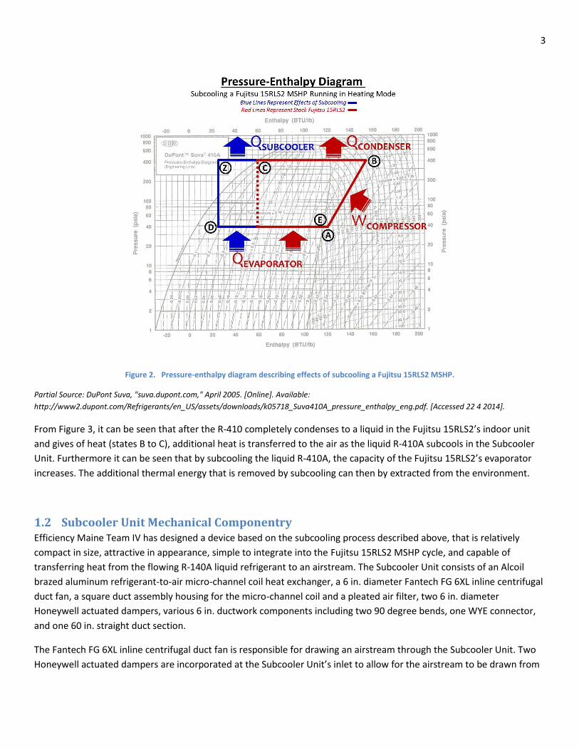
The effect of subcooling on a MSHP running in heating mode can be represented by a pressure-enthalpy diagram
describing the state of the refrigerant at every point in the vapor compression cycle. Specific enthalpy, designated by the
letter h, is the amount of thermal energy (heat) in one unit of mass of a certain substance. In the English Engineering
Unit system, specific enthalpies are typically expressed in BTU/lbm. The specific enthalpy of a substance at a certain
state consists of the substances internal energy per unit mass, plus the product of the pressure and specific volume of
the system, thereby making it a property defined by the substance’s state. An R-410A pressure enthalpy diagram
representing the installed system (Subcooler Unit and Fujitsu 15RLS2) operating in heating mode can be seen below
(Figure 2).
3
Figure 2. Pressure-enthalpy diagram describing effects of subcooling a Fujitsu 15RLS2 MSHP.
Partial Source: DuPont Suva, "suva.dupont.com," April 2005. [Online]. Available:
http://www2.dupont.com/Refrigerants/en_US/assets/downloads/k05718_Suva410A_pressure_enthalpy_eng.pdf. [Accessed 22 4 2014].
From Figure 3, it can be seen that after the R-410 completely condenses to a liquid in the Fujitsu 15RLS2’s indoor unit
and gives of heat (states B to C), additional heat is transferred to the air as the liquid R-410A subcools in the Subcooler
Unit. Furthermore it can be seen that by subcooling the liquid R-410A, the capacity of the Fujitsu 15RLS2’s evaporator
increases. The additional thermal energy that is removed by subcooling can then by extracted from the environment.
1.2 Subcooler Unit Mechanical Componentry Efficiency Maine Team IV has designed a device based on the subcooling process described above, that is relatively
compact in size, attractive in appearance, simple to integrate into the Fujitsu 15RLS2 MSHP cycle, and capable of
transferring heat from the flowing R-140A liquid refrigerant to an airstream. The Subcooler Unit consists of an Alcoil
brazed aluminum refrigerant-to-air micro-channel coil heat exchanger, a 6 in. diameter Fantech FG 6XL inline centrifugal
duct fan, a square duct assembly housing for the micro-channel coil and a pleated air filter, two 6 in. diameter
Honeywell actuated dampers, various 6 in. ductwork components including two 90 degree bends, one WYE connector,
and one 60 in. straight duct section.
The Fantech FG 6XL inline centrifugal duct fan is responsible for drawing an airstream through the Subcooler Unit. Two
Honeywell actuated dampers are incorporated at the Subcooler Unit’s inlet to allow for the airstream to be drawn from
4
either inside or outside and are connected to both branches of the WYE connector respectively. The WYE duct’s third
opening is connected to the 6 in. round connection on one of the two transition ducts, which is then connected to the
inlet side of the 15 in. square duct assembly. Within the square duct assembly, the airstream first passes through the
pleated air filter and then across the micro-channel coil. The subcooler design has incorporated the pleated air filter
before both the micro-channel coil and centrifugal fan to avoid any fouling issues to either the coil or the fan. The
second transition duct is attached to the exit side of the 15 in. square duct assembly.
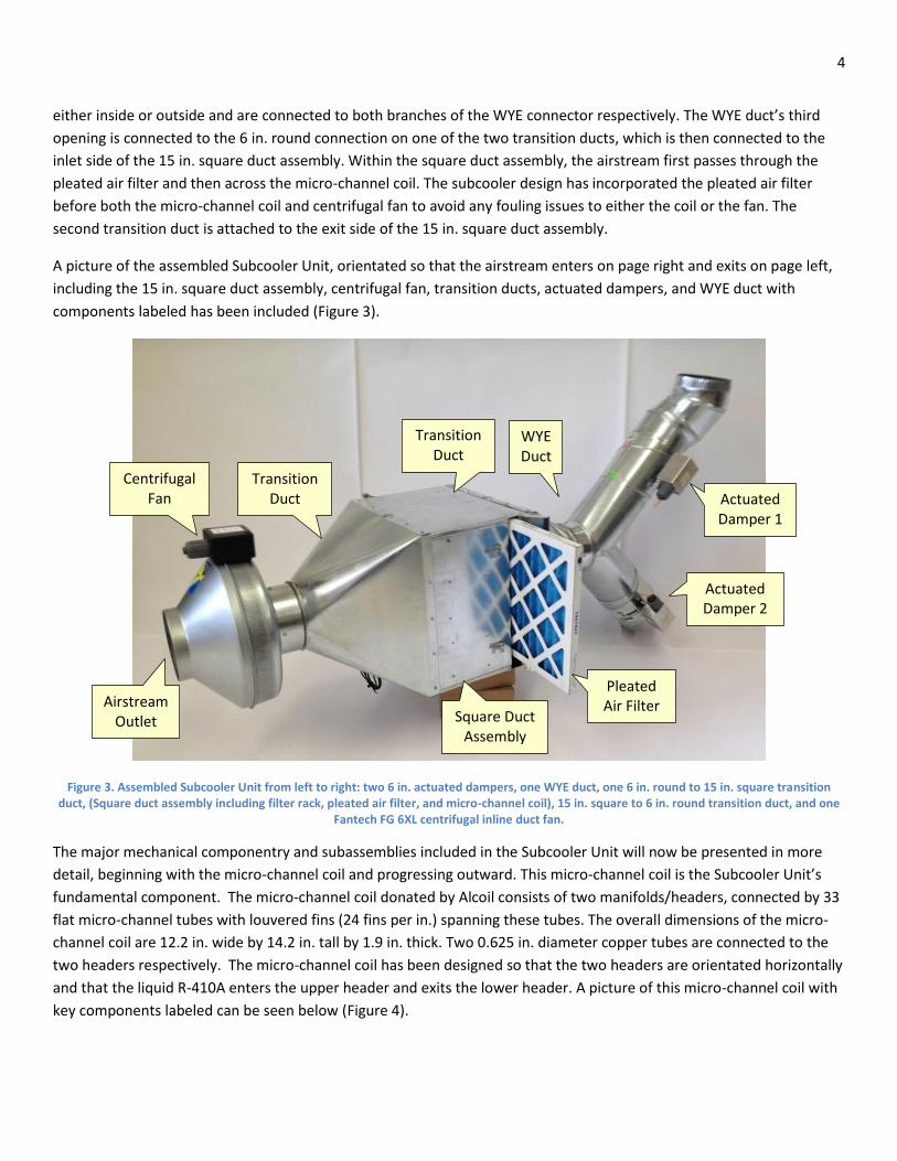
A picture of the assembled Subcooler Unit, orientated so that the airstream enters on page right and exits on page left,
including the 15 in. square duct assembly, centrifugal fan, transition ducts, actuated dampers, and WYE duct with
components labeled has been included (Figure 3).
Figure 3. Assembled Subcooler Unit from left to right: two 6 in. actuated dampers, one WYE duct, one 6 in. round to 15 in. square transition duct, (Square duct assembly including filter rack, pleated air filter, and micro-channel coil), 15 in. square to 6 in. round transition duct, and one
Fantech FG 6XL centrifugal inline duct fan.
The major mechanical componentry and subassemblies included in the Subcooler Unit will now be presented in more
detail, beginning with the micro-channel coil and progressing outward. This micro-channel coil is the Subcooler Unit’s
fundamental component. The micro-channel coil donated by Alcoil consists of two manifolds/headers, connected by 33
flat micro-channel tubes with louvered fins (24 fins per in.) spanning these tubes. The overall dimensions of the micro-
channel coil are 12.2 in. wide by 14.2 in. tall by 1.9 in. thick. Two 0.625 in. diameter copper tubes are connected to the
two headers respectively. The micro-channel coil has been designed so that the two headers are orientated horizontally
and that the liquid R-410A enters the upper header and exits the lower header. A picture of this micro-channel coil with
key components labeled can be seen below (Figure 4).
Square Duct Assembly
Transition Duct
Actuated Damper 2
Pleated Air Filter
WYE Duct
Airstream Outlet
Centrifugal Fan Actuated
Damper 1
Transition Duct

5
Figure 4. Alcoil all-aluminum micro-channel heat exchanger coil.
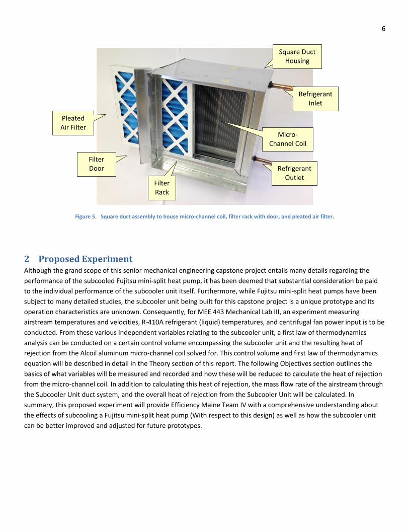
The 15 in. square duct assembly measures 12 in. long and consists of the micro-channel coil, a filter rack with a hinged
access door, the 14 in. nominal square pleated air filter, and a drip pan with a 0.5 in. threaded male fitting located
underneath the micro-channel coil. The 15 in. square duct housing was constructed from 24 gauge galvanized steel
sheet metal and was tungsten inert gas (TIG) welded together. The Subcooler Unit design has the airstream entering the
15. in. square duct assembly so that it passes through the pleated air filter first and then passes through the micro
channel coil. The micro-channel coil is orientated such that the R-410A will enter the upper header and leave the lower
header when the Fujitsu 15RLS2 is running in heating mode. Twin City Sheet Metal was contracted to build this 15 in.
square duct assembly (Figure 5).
Top Manifold
5/8 in. Copper Connection
Bottom Manifold
Micro-channel Tubes Connected With Fins
Support Strut
5/8 in. Copper Connection
6
Figure 5. Square duct assembly to house micro-channel coil, filter rack with door, and pleated air filter.
2 Proposed Experiment Although the grand scope of this senior mechanical engineering capstone project entails many details regarding the
performance of the subcooled Fujitsu mini-split heat pump, it has been deemed that substantial consideration be paid
to the individual performance of the subcooler unit itself. Furthermore, while Fujitsu mini-split heat pumps have been
subject to many detailed studies, the subcooler unit being built for this capstone project is a unique prototype and its
operation characteristics are unknown. Consequently, for MEE 443 Mechanical Lab III, an experiment measuring
airstream temperatures and velocities, R-410A refrigerant (liquid) temperatures, and centrifugal fan power input is to be
conducted. From these various independent variables relating to the subcooler unit, a first law of thermodynamics
analysis can be conducted on a certain control volume encompassing the subcooler unit and the resulting heat of
rejection from the Alcoil aluminum micro-channel coil solved for. This control volume and first law of thermodynamics
equation will be described in detail in the Theory section of this report. The following Objectives section outlines the
basics of what variables will be measured and recorded and how these will be reduced to calculate the heat of rejection
from the micro-channel coil. In addition to calculating this heat of rejection, the mass flow rate of the airstream through
the Subcooler Unit duct system, and the overall heat of rejection from the Subcooler Unit will be calculated. In
summary, this proposed experiment will provide Efficiency Maine Team IV with a comprehensive understanding about
the effects of subcooling a Fujitsu mini-split heat pump (With respect to this design) as well as how the subcooler unit
can be better improved and adjusted for future prototypes.
Filter Door
Square Duct Housing
Pleated Air Filter
Filter Rack
Micro-Channel Coil
Refrigerant Inlet
Refrigerant Outlet
7
3 Objectives: The 11 objectives of this experiment, related to the Fujitsu mini-split heat pump subcooler capstone design project
(Efficiency Maine Team IV), are as follows:
1. Measure airstream velocity profile at the Subcooler Unit outlet using a hot wire anemometer inserted into the
ductwork using a vertical traversing apparatus.
2. Measure and record Subcooler Unit inlet and outlet airstream temperatures using two type T thermocouples
and a USB-5104, battery-powered 4-channel thermocouple data logger.
3. Measure and record R-410A (saturated or subcooled liquid state) temperature at the inlet and outlet of the
Alcoil micro-channel coil using two type T thermocouples affixed to the copper refrigerant lines, as well as the
previously mentioned USB thermocouple data logger.
4. Measure voltage drop across the entire Subcooler Unit, as well as across the Fantech FG 6XL centrifugal inline
duct fan, the two Honeywell actuated dampers, and the Arduino Uno using a clamp style induction ammeter.
5. Measure current drawn by the entire Subcooler Unit, as well as by the Fantech FG 6XL centrifugal inline duct fan,
the two Honeywell actuated dampers, and the Arduino Uno using a clamp style induction ammeter.
6. Determine mass flow rate of the airstream drawn through the Subcooler Unit.
7. Determine amount of liquid R-410A refrigerant occurring in micro-channel coil in Subcooler Unit.
8. Determine electrical power consumed by the entire Subcooler Unit, as well as by the Fantech FG 6XL centrifugal
inline duct fan, the two Honeywell actuated dampers, and the Arduino Uno.
9. Determine heat rejection from micro-channel coil located in the Subcooler Unit using a first law of
thermodynamics analysis and specified control volume on the Subcooler Unit.
10. Determine overall heat of rejection from the Subcooler Unit to the photocopier room.
11. Determine operating efficiency of the Subcooler Unit.

8
4 Apparatus, Equipment, Instrumentation As previously mentioned in the Introduction section of this report, a Fujitsu 15RLS2 mini-split heat pump, with R-410A as
the working refrigerant, is retrofitted with a Subcooler Unit constructed from an Alcoil brazed aluminum micro-channel
coil, an inline centrifugal duct fan, and various ducting components. These ducting components consist of 6 inch round
duct, 15 inch square duct, 6 inch round to 15 inch square transition duct, two six inch round actuated dampers and a 14
inch square pleated air filter and can be seen below in a translucent SolidWorks model of the subcooler unit (Figure 6).
This Subcooler Unit has been built to determine the effect of subcooling on the Fujitsu heat pump’s performance. It has
been predicted that the subcooler will raise the COP of the heat pump cycle by producing additional heat of rejection
with the same amount of compressor electrical work and minimal additional centrifugal fan electrical work.
Figure 6. Translucent SolidWorks Model of Subcooler Unit Showing Location of Micro-Channel Coil, Refrigerant Lines, and Pleated Filter
As defined in the Objectives section of this report, several variables relating to the performance of the Subcooler Unit
will be recorded. These consist of the airstream temperature at the inlet and outlet of the Subcooler Unit, the airstream
velocity profile at several points along the length of the subcooler unit, the electrical work input to the centrifugal fan,
and the temperature of the R-410A (liquid state) at both the inlet and outlet of the Alcoil micro-channel coil. The
electrical power of the fan is monitored with a wattage meter. The four temperatures will be recorded using four
individual type T thermocouples and a thermocouple data logger, capable of recording up to 1.6 million measurements
at a user prescribed frequency. The temperature data can easily be imported from the thermocouple data logger to
Microsoft Excel or a text file. A PC equipped with Microsoft Excel can then be used to reduce the data. The airstream
9
velocity profiles will be recorded using a hot wire anemometer inserted into the subcooler unit via several holes cut into
the subcooler duct system. A collar and a ruler are used to accurately determine the depth that the hot wire
anemometer is plunged into the duct work, so that a velocity profile in the vertical direction can be constructed. With
respect to this experiment, the only critical airstream velocity profile is the one measured at the outlet of the subcooler
duct system, since it will be used in the subsequent first law of thermodynamics data reduction to calculate the
airstream mass flow rate. It will be shown later in this report that this kinetic energy term due to the airstream velocity
is negligible compared to the other terms.
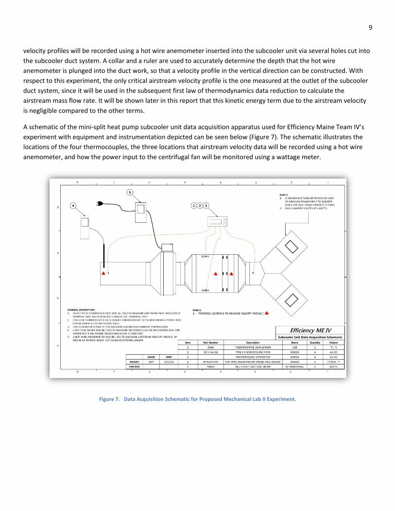
A schematic of the mini-split heat pump subcooler unit data acquisition apparatus used for Efficiency Maine Team IV’s
experiment with equipment and instrumentation depicted can be seen below (Figure 7). The schematic illustrates the
locations of the four thermocouples, the three locations that airstream velocity data will be recorded using a hot wire
anemometer, and how the power input to the centrifugal fan will be monitored using a wattage meter.
Figure 7. Data Acquisition Schematic for Proposed Mechanical Lab II Experiment.
10
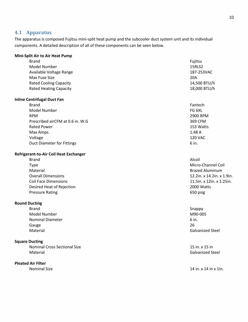
4.1 Apparatus The apparatus is composed Fujitsu mini-split heat pump and the subcooler duct system unit and its individual
components. A detailed description of all of these components can be seen below.
Mini-Split Air to Air Heat Pump Brand Fujitsu Model Number 15RLS2 Available Voltage Range 187-253VAC Max Fuse Size 20A
Rated Cooling Capacity 14,500 BTU/h Rated Heating Capacity 18,000 BTU/h
Inline Centrifugal Duct Fan Brand Fantech
Model Number FG 6XL RPM 2900 RPM Prescribed airCFM at 0.6 in. W.G 369 CFM
Rated Power 153 Watts Max Amps. 1.48 A Voltage 120 VAC Duct Diameter for Fittings 6 in.
Refrigerant-to-Air Coil Heat Exchanger Brand Alcoil Type Micro-Channel Coil Material Brazed Aluminum
Overall Dimensions 12.2in. x 14.2in. x 1.9in. Coil Face Dimensions 11.5in. x 12in. x 1.25in. Desired Heat of Rejection 2000 Watts
Pressure Rating 650 psig Round Ducting Brand Snappy Model Number M90-005
Nominal Diameter 6 in. Gauge 26
Material Galvanized Steel
Square Ducting Nominal Cross Sectional Size 15 in. x 15 in
Material Galvanized Steel
Pleated Air Filter Nominal Size 14 in. x 14 in x 1in.

11
4.2 Equipment and Instrumentation The equipment and instrumentation will be employed to monitor and record the previously defined variables needed for
this experiment. A detailed description of these can be seen below.
Hot Wire Anemometer Brand Omega Engineering
Model Number HHF2005HW Velocity Range 30-3940 ft./min Velocity Uncertainty ± 1ft/min Temp. Range 32 °F to 122 °F
Thermocouple Wire Brand Omega Engineering Type T Model Number GG-T-24-SLE Temp. Range -328 to 2282 °F Diameter 0.032 in.
Uncertainty ±1.8 °F Thermocouple Data Logger Brand USB Model Number 5104
Uncertainty ±0.07 °F Thermocouple Input Channels 4 Memory 4 MB Measurement Storage 1.6 Million Display LCD Screen
Multimeter Brand Fluke Model Number 115
Maximum Voltage 600V Accuracy +([% of reading +[counts])*0.5%+2.0
Ammeter Brand Yokogawa Model Number CL120
Accuracy 2.0+(50~1kHz)

12
5 Theory
5.1.1 Calculating Heat of Rejection from Subcooler Unit
To accurately analyze the airstream flowing through the Subcooler Unit, a first law of thermodynamics equation can be
written on an appropriate control volume. This control volume is defined as encompassing the entire Subcooler Unit
with boundaries set a few inches away from the duct inlets and outlets. Due to this assumption, the kinetic energy term
due to the airstream velocity at either inlet (outside or inside) is considered to be zero. In contrast, the kinetic energy
term of the flowing air at the outlet is included. There is electrical work input to the centrifugal fan that is passing into
this control volume boundary and is defined as Wfan, a negative value by thermodynamic sign convention. Since the
Subcooler Unit is relatively short and since the airstream flowing within is moving quickly, the defined control volume
will be considered to be adiabatic. Perhaps there are small heat gains (to ambient) from the airstream before the micro-
channel coil and small heat losses (to ambient) after, but they can both be considered negligible. The two mass flow
rates passing the boundary of the defined control volume are the airstream mass flow rate mdot_air and the R-410A mass
flow rate mdot_R410A. All of these variables with corresponding units can be seen below in tabular form (Table 1). The
following data reduction theory section will be conducted using the English engineering unit system and therefore
several conversions are needed and will be described as needed.
Table 1. Variables used to determine heat of rejection from the Subcooler Unit.
Independent Variable Units
Wfan Watts
Vair_outlet Feet per Minute
Diaround_duct Inches
Tair_outlet Degrees Fahrenheit
Tair_inlet Degrees Fahrenheit
TR410A_outlet Degrees Fahrenheit
TR410A_inlet Degrees Fahrenheit
Dependent Variable
mdot_air Pound Mass per Hour
Qmicrochannel_coil BTU per Hour
Since the R-410A refrigerant is in a liquid state at both the inlet and outlet of the Alcoil micro-channel coil, the
corresponding specific enthalpies in BTU/lbm can be found in an R-410A thermodynamic properties table provided by
DuPont. Although the R-410A liquid at the outlet of the micro-channel coil will exist in a subcooled state, not saturated,
the enthalpy values are essentially the same for both at the same temperature. The three engineering constants Cp_air,
ρair, and gc_eng used the analysis of the Subcooler Unit can be seen below (Table 2).
Table 2. Engineering constants used in data reduction.
CP_air ρair gc_eng
0.24 BTU/lbm-°F 0.075 lbm/ft3
32.174 lbm-ft/lbf-s2

13
It should also be noted that the airstream mass flow rate and the velocity are dependent upon each other. The mass
flow rate of the air can be calculated from the average airstream velocity of the airstream profile recorded at the
subcooler outlet duct, the cross sectional area of this outlet duct, and the defined density of the airstream flowing
through the subcooler as seen in Equation 21 below.
Eq.1
The formula for the cross sectional area of the 6 in. round exit duct, as well as two needed conversion factors to convert
form square inches square feet and from minutes to hours , can be substituted into Equation 21 so that an airstream
mass flow rate with units of lbm/hour results and can be seen below in Equation 22.
Eq.2
The two needed conversion factors used in Equation # so that a mass flow rate of lbm/hour results are as follows:
Eq.3
Eq.4
From the defined airstream mass flow rate, as well as previous definitions and assumptions, a first law of
thermodynamics equation written on the defined control volume encompassing the Subcooler Unit is as follows:
Due to the previously mentioned adiabatic assumptions, Qsubcooler is essentially zero. The electrical power rate Wfan is a
negative value in thermodynamic sign convention since it is into the defined control volume. Equation 5 employs three
conversion equalities, so that units are consistent throughout. The first corresponds to the centrifugal fan electrical work
input and the second corresponds to the kinetic energy term due to the airstream velocity at the subcooler ductwork
exit. These three conversion equalities are as follows:
Eq.6
mdot_air vair_outlet Areaoutlet air
mdot_air vair_outlet
4
Diaround_duct2
1 ft
2
144 in2
60 min
1 hr
air
11 ft
2
144 in2
160 min
1 hr
Qsubcooler Wfan
3.412BT U
hr
1 W
mdot_air Cp_air Tair_outlet Tair_inlet
vair_outlet2 1 min
2
3600s2
778.169lbf ft
1 BT U
2 gc_eng
mdot_R410A hR410A_outlet hR410A_inlet
1
3.412BT U
hr
1 W
Eq.5
14
Eq.7
Eq.8
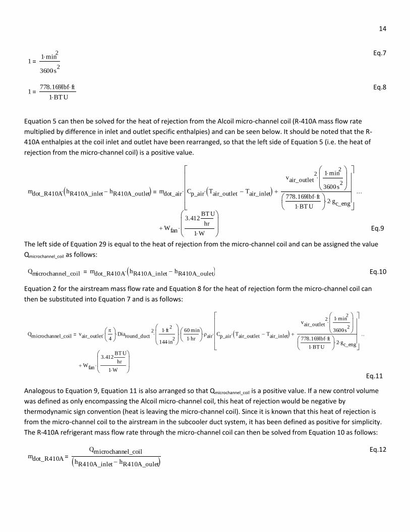
Equation 5 can then be solved for the heat of rejection from the Alcoil micro-channel coil (R-410A mass flow rate
multiplied by difference in inlet and outlet specific enthalpies) and can be seen below. It should be noted that the R-
410A enthalpies at the coil inlet and outlet have been rearranged, so that the left side of Equation 5 (i.e. the heat of
rejection from the micro-channel coil) is a positive value.
The left side of Equation 29 is equal to the heat of rejection from the micro-channel coil and can be assigned the value
Qmicrochannel_coil as follows:
Eq.10
Equation 2 for the airstream mass flow rate and Equation 8 for the heat of rejection form the micro-channel coil can
then be substituted into Equation 7 and is as follows:
Analogous to Equation 9, Equation 11 is also arranged so that Qmicrochannel_coil is a positive value. If a new control volume
was defined as only encompassing the Alcoil micro-channel coil, this heat of rejection would be negative by
thermodynamic sign convention (heat is leaving the micro-channel coil). Since it is known that this heat of rejection is
from the micro-channel coil to the airstream in the subcooler duct system, it has been defined as positive for simplicity.
The R-410A refrigerant mass flow rate through the micro-channel coil can then be solved from Equation 10 as follows:
Eq.12
11 min
2
3600s2
1778.169lbf ft
1 BTU
mdot_R410A hR410A_inlet hR410A_outlet mdot_air Cp_air Tair_outlet Tair_inlet
vair_outlet2 1 min
2
3600s2
778.169lbf ft
1 BT U
2 gc_eng
Wfan
3.412BT U
hr
1 W
Qmicrochannel_coil mdot_R410A hR410A_inlet hR410A_oulet
Qmicrochannel_coil vair_outlet
4
Diaround_duct2
1 ft
2
144 in2
60 min
1 hr
air Cp_air Tair_outlet Tair_inlet
vair_outlet2 1 min
2
3600s2
778.169lbf ft
1 BT U
2 gc_eng
Wfan
3.412BT U
hr
1 W
mdot_R410A
Qmicrochannel_coil
hR410A_inlet hR410A_oulet
Eq.9
Eq.11
15
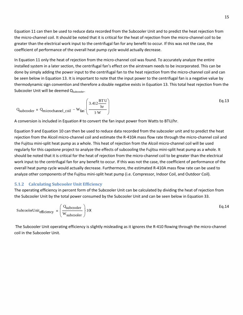
Equation 11 can then be used to reduce data recorded from the Subcooler Unit and to predict the heat rejection from
the micro-channel coil. It should be noted that it is critical for the heat of rejection from the micro-channel coil to be
greater than the electrical work input to the centrifugal fan for any benefit to occur. If this was not the case, the
coefficient of performance of the overall heat pump cycle would actually decrease.
In Equation 11 only the heat of rejection from the micro-channel coil was found. To accurately analyze the entire
installed system in a later section, the centrifugal fan’s effect on the airstream needs to be incorporated. This can be
done by simply adding the power input to the centrifugal fan to the heat rejection from the micro-channel coil and can
be seen below in Equation 13. It is important to note that the input power to the centrifugal fan is a negative value by
thermodynamic sign convention and therefore a double negative exists in Equation 13. This total heat rejection from the
Subcooler Unit will be deemed QSubcooler.
Eq.13
A conversion is included in Equation # to convert the fan input power from Watts to BTU/hr.
Equation 9 and Equation 10 can then be used to reduce data recorded from the subcooler unit and to predict the heat
rejection from the Alcoil micro-channel coil and estimate the R-410A mass flow rate through the micro-channel coil and
the Fujitsu mini-split heat pump as a whole. This heat of rejection from the Alcoil micro-channel coil will be used
regularly for this capstone project to analyze the effects of subcooling the Fujitsu mini-split heat pump as a whole. It
should be noted that it is critical for the heat of rejection from the micro-channel coil to be greater than the electrical
work input to the centrifugal fan for any benefit to occur. If this was not the case, the coefficient of performance of the
overall heat pump cycle would actually decrease. Furthermore, the estimated R-410A mass flow rate can be used to
analyze other components of the Fujitsu mini-split heat pump (i.e. Compressor, Indoor Coil, and Outdoor Coil).
5.1.2 Calculating Subcooler Unit Efficiency
The operating efficiency in percent form of the Subcooler Unit can be calculated by dividing the heat of rejection from
the Subcooler Unit by the total power consumed by the Subcooler Unit and can be seen below in Equation 33.
Eq.14
The Subcooler Unit operating efficiency is slightly misleading as it ignores the R-410 flowing through the micro-channel
coil in the Subcooler Unit.
Qsubcooler Qmicrochannel_coil Wfan
3.412BT U
hr
1 W
SubcoolerUnitefficiency
Qsubcooler
Wsubcooler
100
16
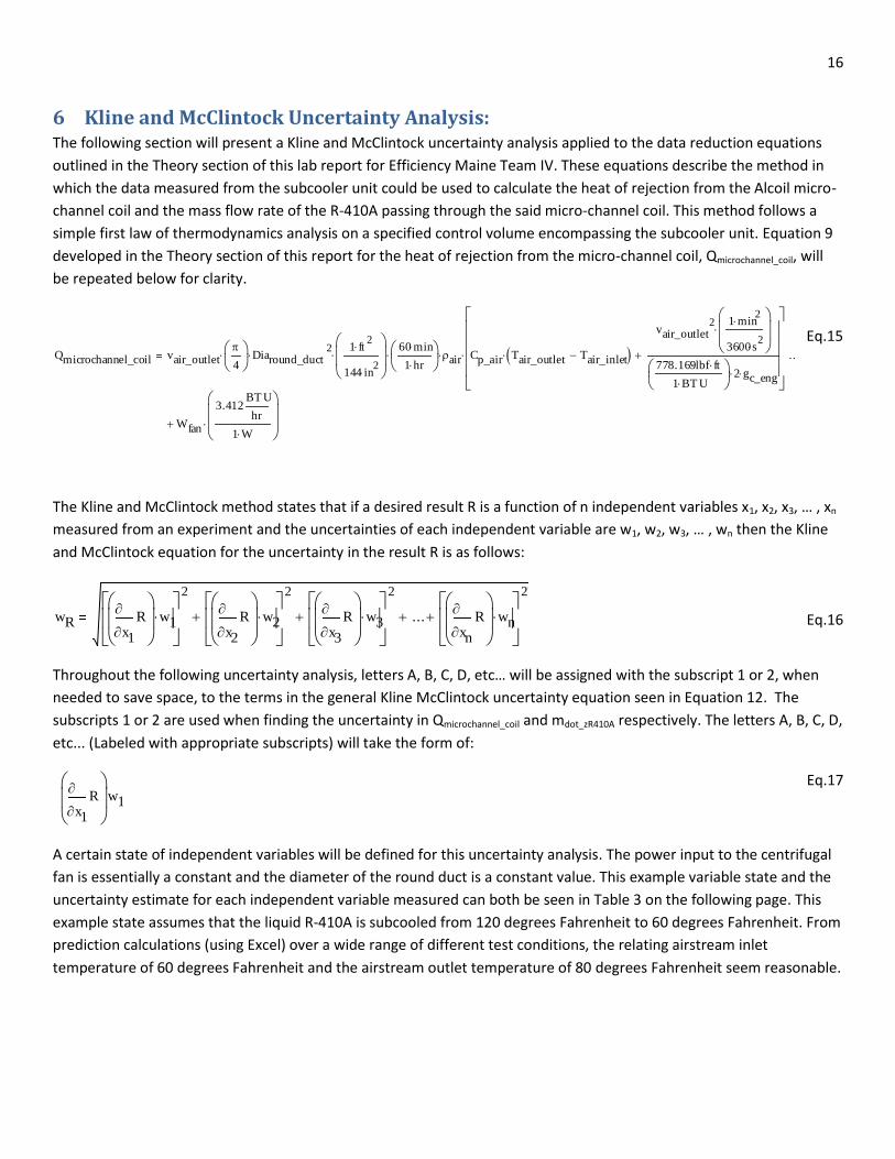
6 Kline and McClintock Uncertainty Analysis: The following section will present a Kline and McClintock uncertainty analysis applied to the data reduction equations
outlined in the Theory section of this lab report for Efficiency Maine Team IV. These equations describe the method in
which the data measured from the subcooler unit could be used to calculate the heat of rejection from the Alcoil micro-
channel coil and the mass flow rate of the R-410A passing through the said micro-channel coil. This method follows a
simple first law of thermodynamics analysis on a specified control volume encompassing the subcooler unit. Equation 9
developed in the Theory section of this report for the heat of rejection from the micro-channel coil, Qmicrochannel_coil, will
be repeated below for clarity.
The Kline and McClintock method states that if a desired result R is a function of n independent variables x1, x2, x3, … , xn
measured from an experiment and the uncertainties of each independent variable are w1, w2, w3, … , wn then the Kline
and McClintock equation for the uncertainty in the result R is as follows:
Throughout the following uncertainty analysis, letters A, B, C, D, etc… will be assigned with the subscript 1 or 2, when
needed to save space, to the terms in the general Kline McClintock uncertainty equation seen in Equation 12. The
subscripts 1 or 2 are used when finding the uncertainty in Qmicrochannel_coil and mdot_zR410A respectively. The letters A, B, C, D,
etc... (Labeled with appropriate subscripts) will take the form of:
Eq.17
A certain state of independent variables will be defined for this uncertainty analysis. The power input to the centrifugal
fan is essentially a constant and the diameter of the round duct is a constant value. This example variable state and the
uncertainty estimate for each independent variable measured can both be seen in Table 3 on the following page. This
example state assumes that the liquid R-410A is subcooled from 120 degrees Fahrenheit to 60 degrees Fahrenheit. From
prediction calculations (using Excel) over a wide range of different test conditions, the relating airstream inlet
temperature of 60 degrees Fahrenheit and the airstream outlet temperature of 80 degrees Fahrenheit seem reasonable.
Qmicrochannel_coil vair_outlet
4
Diaround_duct2
1 ft
2
144 in2
60 min
1 hr
air Cp_air Tair_outlet Tair_inlet
vair_outlet2 1 min
2
3600s2
778.169lbf ft
1 BT U
2 gc_eng
Wfan
3.412BT U
hr
1 W
wRx1
R
w1
2
x2
R
w2
2
x3
R
w3
2
...xn
R
wn
2'
x1
R
w1
Eq.15
Eq.16

17
Table 3 – Example State and Uncertainty Estimates for all Independent Variables
Independent
Variable
Wfan Vair_outl
et
Tair_ou
tlet
Tair_inlet TR410A_outlet TR410A_inlet Diaround_duct hR410A_inlet hR410A_outlet
Value used
for Analysis
149
W
1830
ft/min
80°F 60°F 60°F 120°F 6in. 60.78
BTU/lbm
35.27
BTU/lbm
Uncertainty
Estimate
0.2% 1
ft/min
1.8°F 1.8°F 1.8°F 1.8°F 0.05in. 1
BTU/lbm
1
BTU/lbm
The uncertainty estimates defined in Table 3 come from manufacture specifications for the various instruments being
used. The Apparatus, Equipment and Instrumentation section of this report presents a more detailed description of the
instrumentation used. For this Kline and McClintock uncertainty analysis, the most conservative (within reason)
uncertainty estimates were used.
The heat of rejection from the micro-channel coil, calculated from the defined state seen in Table 3, is 2432 Watts. Since
the R-410A is either in a saturated liquid or subcooled liquid state, respective enthalpies can be found from the
saturated tables with reasonable accuracy (that of the subcooled liquid varies little from the saturated liquid). From
these R-410A specific enthalpy tables it was deemed that the 1.8°F uncertainty in measuring (with thermocouples) the
R-410A temperatures corresponds to about 1 BTU/lbm in specific enthalpy uncertainty. Therefore this uncertainty
estimate will be used later in this section when calculating the R-410A mass flow rate uncertainty. By applying the Kline
and McClintock method to Equation 9, the uncertainty in calculating the heat of rejection from the micro-channel coil
Qmicrochannel_coil can be found as:
A1Wfan
vair_outlet
4
Diaround_duct2
1 ft
2
144 in2
60 min
1 hr
air Cp_air Tair_outlet Tair_inlet
vair_outlet2 1 min
2
3600s2
778.169lbf ft
1 BT U
2 gc_eng
Wfan
3.412BT U
hr
1 W
wW_fan
B1Tair_outlet
vair_outlet
4
Diaround_duct2
1 ft
2
144 in2
60 min
1 hr
air Cp_air Tair_outlet Tair_inlet
vair_outlet2 1 min
2
3600s2
778.169lbf ft
1 BT U
2 gc_eng
Wfan
3.412BT U
hr
1 W
wT_air_outlet
C1Tair_inlet
vair_outlet
4
Diaround_duct2
1 ft
2
144 in2
60 min
1 hr
air Cp_air Tair_outlet Tair_inlet
vair_outlet2 1 min
2
3600s2
778.169lbf ft
1 BT U
2 gc_eng
Wfan
3.412BT U
hr
1 W
wT_air_inlet
Eq.19
Eq.20
Eq.18

18
Eq.23
The percent uncertainty in calculating the heat of rejection from the micro-channel coil can then be calculated by
comparing the uncertainty to the actual example value as:
Eq.24
The numerical results from Equations 18 through 24 can be seen below in Table 4.
Table 4 – Numerical Results from Uncertainty Analysis for Calculating Qmicrochannel_coil
A1 0.298W
B1 60.408W
C1 -60.408W
D1 1.244W
E1 11.19W
wQmicrochannel_coil 86.169W
Percent_w Qmicrochannel_coil 10.503%
From Table 4, it can be easily seen that the airstream inlet and outlet temperatures (these relate to B1 and C1) contribute
the most to the overall uncertainty in calculating Qmicrochannel_coil. It should be noted that the uncertainty in measuring
these temperatures can most likely be reduced, which will lead to less uncertainty in calculating Qmicrochannel_coil. The
percent uncertainty of 10.503% when calculating the heat of rejection from the micro-channel coil is marginally
reasonable for the needs of this capstone project. With foreseeable thermocouple work, this percent uncertainty can
D1vair_outlet
vair_outlet
4
Diaround_duct2
1 ft
2
144 in2
60 min
1 hr
air Cp_air Tair_outlet Tair_inlet
vair_outlet2 1 min
2
3600s2
778.169lbf ft
1 BT U
2 gc_eng
Wfan
3.412BT U
hr
1 W
wv_air_outlet
E1Diaround_duct
vair_outlet
4
Diaround_duct2
1 ft
2
144 in2
60 min
1 hr
air Cp_air Tair_outlet Tair_inlet
vair_outlet2 1 min
2
3600s2
778.169lbf ft
1 BT U
2 gc_eng
Wfan
3.412BT U
hr
1 W
wDia_round_duct
wQ_microchannel_coil A12
B12
C12
D12
E12
Percent_wQmicrochannel_coil
wQmicrochannel_coil
Qmicrochannel_coil
Eq.21
Eq.22

19
hopefully be reduced to around five percent uncertainty. By applying the Kline and McClintock method to Equation 12,
the uncertainty in calculating the R-410A mass flow rate can be calculated as follows:
Eq.25
Eq.26
Eq.27
The percent uncertainty in calculating the R-410A mass flow rate can be found by comparing the calculated uncertainty
to the actual example value as:
Eq.28
The numerical results from Equations 25 through 28 for the uncertainty in calculating the R-410A mass flow rate can be
seen below in Table 5.
Table 5 - Numerical Results from Uncertainty Analysis for R-410A Mass Flow Rate
A2 11.526lbm/hr
B2 2.151lbm/hr
C2 -2.151lbm/hr
wm_dot_R410A 11.92lbm/hr
Percent_ wm_dot_R410A 10.863%
It can be seen from Table 5 that the uncertainty from calculating the heat of rejection from the micro-channel coil has
the greatest influence on the uncertainty in calculating the R-410A mass flow rate through the micro-channel coil. This is
due to the previously discussed high uncertainty related to measuring the airstream inlet and outlet temperatures. Since
this R-410A mass flow rate will be used elsewhere in the capstone project for important calculations it seems pertinent
to reduce its uncertainty.
A2Qmicrochannel_coil
Qmicrochannel_coil
hR410A_inlet hR410A_outlet
wQ_microchannel_coil
B2hR410A_outlet
Qmicrochannel_coil
hR410A_inlet hR410A_outlet
wh_R410A_outlet
C2hR410A_inlet
Qmicrochannel_coil
hR410A_inlet hR410A_outlet
wh_R410A_inlet
Percent_wm_dot_R410A
wm_dot_R410A
mdot_R410A
20
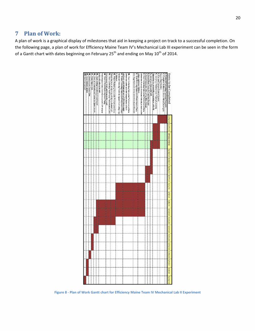
7 Plan of Work: A plan of work is a graphical display of milestones that aid in keeping a project on track to a successful completion. On
the following page, a plan of work for Efficiency Maine Team IV’s Mechanical Lab III experiment can be seen in the form
of a Gantt chart with dates beginning on February 25th and ending on May 10th of 2014.
Figure 8 - Plan of Work Gantt chart for Efficiency Maine Team IV Mechanical Lab II Experiment

21
8 Procedure:
8.1 Measuring Airstream Velocity Profile: The airstream velocity profile at the Subcooler Unit outlet in the round duct is measured to determine an average
velocity the mass flow rate of the air. The velocity profile is measured according to ASHRAE standards, as indicated in
the Objective section of this proposal report, using an Omega Engineering hot wire anemometer. To accurately measure
the airstream velocity with the hot wire anemometer, an apparatus constructed out of a twelve-inch ruler, a six-inch
hose clamp, and two aluminum “guides” that are clamped onto the ruler is used to traverse the six inch round duct with
said hot wire anemometer .The probe shaft of the hot wire anemometer is inserted via a hole, and the two aluminum
guides apparatus will keep the probe shaft perpendicular to the airflow, which is necessary to achieve accurate results
the hot-wire anemometer. The apparatus for inserting the hot wire anemometer was inspired by a similar device that
was used to traverse a much smaller PVC pipe with a pitot-static tube to determine the airstream velocity profile in the
Undergraduate Mechanical Engineering course “Mechanical Laboratory I”. A photograph of the anemometer apparatus
and one of the members of Efficiency Maine Team IV using the apparatus to conduct the experiment can be seen below
(Figure 9). For this experiment, a datum is taken at the bottom surface of the interior of the duct wall.
Figure9. Hot Wire Anemometer and Traversing Guide Apparatus.
The velocity profile is measured at a location in the ducting of the Subcooler Unit where the airstream has reached fully
developed flow. According to ASHRAE standards, flow in a duct is fully developed if it is 7.5 hydraulic diameters
Traversing Guide Apparatus
Hot Wire Anemometer Probe
Hot Wire Anemometer Display
22
downstream and 3 hydraulic diameters upstream from any flow disturbances. The average airstream velocity is
determined by applying the Log-Linear Rule for flow in circular ducts using the measured data collected with the hot
wire anemometer.
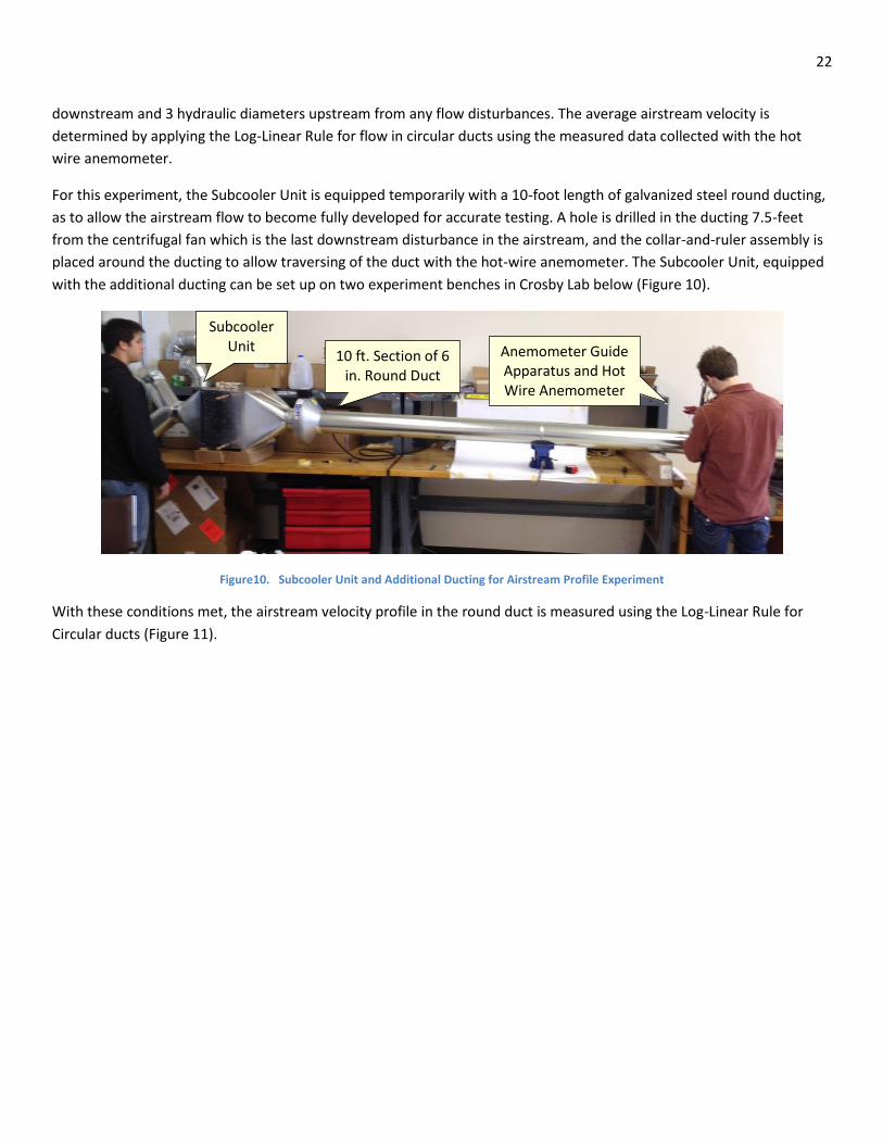
For this experiment, the Subcooler Unit is equipped temporarily with a 10-foot length of galvanized steel round ducting,
as to allow the airstream flow to become fully developed for accurate testing. A hole is drilled in the ducting 7.5-feet
from the centrifugal fan which is the last downstream disturbance in the airstream, and the collar-and-ruler assembly is
placed around the ducting to allow traversing of the duct with the hot-wire anemometer. The Subcooler Unit, equipped
with the additional ducting can be set up on two experiment benches in Crosby Lab below (Figure 10).
Figure10. Subcooler Unit and Additional Ducting for Airstream Profile Experiment
With these conditions met, the airstream velocity profile in the round duct is measured using the Log-Linear Rule for
Circular ducts (Figure 11).
Subcooler Unit
10 ft. Section of 6 in. Round Duct
Anemometer Guide Apparatus and Hot Wire Anemometer

23
Figure11. Velocity measurement locations specified by the Log-Linear Rule for Circular ducts
(Source: ASHRAE Fundamentals Handbook, Chapter 36.13)
Figure 33 illustrates where to make airflow measurements in a round duct with any given interior diameter to determine
an average airstream-flow-rate in the duct as recommended by ASHRAE. Summing the airstream flow rates at each
location and dividing by the total number of measurements taken determines the average-air-stream flow rate in the
ducting.
The airstream velocity test was conducted two times to assure accurate results. A 4 ft. long section of 6 inch round duct
work is incorporated in the Subcooler Unit after the centrifugal fan. Thus, it is believed that the airstream will be
essentially fully developed when it is measured at the subcooler duct outlet.
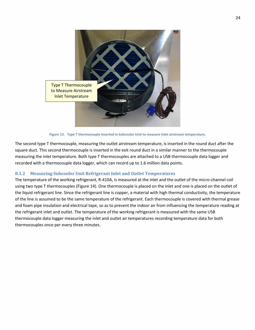
8.1.1 Measuring Subcooler Unit Airstream Inlet and Outlet Temperatures
The Subcooler unit airstream temperature is measured with two type T thermocouples positioned at the inlet and outlet
of the Subcooler Unit. The first thermocouple, measuring the inlet airstream temperature, is inserted inside the round
duct portion of the inlet transition duct so as to measure the inlet air temperature regardless of the damper position
(Drawing airstream from inside or outside) and can be seen below (Figure 13).
24
Figure 13. Type T thermocouple inserted in Subcooler Unit to measure inlet airstream temperature.
The second type T thermocouple, measuring the outlet airstream temperature, is inserted in the round duct after the
square duct. This second thermocouple is inserted in the exit round duct in a similar manner to the thermocouple
measuring the inlet temperature. Both type T thermocouples are attached to a USB thermocouple data logger and
recorded with a thermocouple data logger, which can record up to 1.6 million data points.
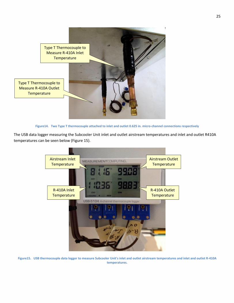
8.1.2 Measuring Subcooler Unit Refrigerant Inlet and Outlet Temperatures
The temperature of the working refrigerant, R-410A, is measured at the inlet and the outlet of the micro-channel coil
using two type T thermocouples (Figure 14). One thermocouple is placed on the inlet and one is placed on the outlet of
the liquid refrigerant line. Since the refrigerant line is copper, a material with high thermal conductivity, the temperature
of the line is assumed to be the same temperature of the refrigerant. Each thermocouple is covered with thermal grease
and foam pipe insulation and electrical tape, so as to prevent the indoor air from influencing the temperature reading at
the refrigerant inlet and outlet. The temperature of the working refrigerant is measured with the same USB
thermocouple data logger measuring the inlet and outlet air temperatures recording temperature data for both
thermocouples once per every three minutes.
Type T Thermocouple to Measure Airstream
Inlet Temperature
25
Figure14. Two Type T thermocouple attached to inlet and outlet 0.625 in. micro-channel connections respectively
The USB data logger measuring the Subcooler Unit inlet and outlet airstream temperatures and inlet and outlet R410A
temperatures can be seen below (Figure 15).
Figure15. USB thermocouple data logger to measure Subcooler Unit's inlet and outlet airstream temperatures and inlet and outlet R-410A temperatures.
Type T Thermocouple to Measure R-410A Inlet
Temperature
R-410A Inlet Temperature
Airstream Outlet Temperature
Airstream Inlet Temperature
R-410A Outlet Temperature
Type T Thermocouple to Measure R-410A Outlet
Temperature

26
After running a performance test trial, the recorded temperature data from the USB thermocouple data logger for the
four the type T thermocouples can be easily exported as CSV file to Excel.
8.1.3 Measuring Subcooler Unit Input Power
To determine the power drawn by the Subcooler Unit, the total current drawn by the Subcooler Unit was measured
using a clamp style induction ammeter and the voltage drop across the Subcooler Unit was measured using a standard
multimeter. After measuring the current in amperes and the voltage drop in VAC the power drawn by the Subcooler Unit
could be calculated by multiplying the two values as seen below in Equation 29.
Eq.29
This total power input to the Subcooler Unit will be used when calculating the Subcooler Unit efficiency, as well as the
installed system’s COP. Since the centrifugal fan is set to a certain speed, and that one of two actuated dampers will
always be powered, it will be assumed that the total power drawn by the Subcooler Unit is a constant. This assumption
was verified after the total power drawn by the Subcooler Unit was measured on several different occasions.
The power input to the Subcooler Unit as a whole includes power input to the Fantech FG-6XL centrifugal duct fan,
power input to one of the two Honeywell actuated dampers (only one damper is selected at a time), and power input to
the Arduino micro-controller, which also powers the SPDT relay module board. Each of these individual power inputs
could be found by applying the same ammeter and multimeter to correct wires and terminal blocks respectively. The
power drawn by each of the three components can then be found the same way as Equation 18.
Eq.30
Eq.31
Eq.32
It can be seen from Equation 20 that the power drawn by the Arduino micro controller board is parasitic when
compared to the power drawn by the fan and dampers.
Wsubcooler Isubcooler Vsubcooler
Wcentrifugal_fan Ifan Vfan 1.16A( ) 113 VAC( ) 131.08W
Wdamper Idamper Vdamper 0.33A( ) 26VAC( ) 8.58 W
Warduino IArduino VArduino 0.01A( ) 113( ) 1.13W

27
9 Expected Results: From the various independent variables that will are monitored in this experiment, there are three key results desired.
As evident in the Theory section of this report, they consist of the average airstream mass flow rate through the
subcooler unit, the heat of rejection from the micro-channel coil, and the mass flow of the R-410A through the micro-
channel coil. There are several intermediate results that exist as well, including calculating the cross sectional area of the
6 inch round duct, calculating an average airstream velocity using the log-linear or Log-Tchebycheff method for the
respective duct section and interpolating R-410A specific enthalpy values from the measured R-410A temperatures.
From manufacture supplied data from Fantech for the FG-6XL centrifugal fan, it is expected that the volumetric flow rate
be around 360 aCFM, which corresponds to a mass flow rate of 1620 pounds mass per hour. These are both at an
estimated static pressure present in the subcooler duct system of about 0.6 inches W.G. From extensive prediction
calculations (Not included in the report) using performance data of a Fujitsu 15RLS2 mini-split heat pump, it is expected
that the heat of rejection from the micro-channel coil range between 1000 watts and 2500 watts. The high end of this
heat rejection range would only exist for high levels of liquid refrigerant subcooling. From these prediction equations, a
heat of rejection of approximately 2000 watts seems to be a reasonably value for the subcooler unit to generate on a
regular basis. If this is the case, then the retro fit of the subcooler unit to the Fujitsu mini-split heat pump can be
considered a success. Expected R-410A mass flow rates through the micro-channel coil in the subcooler unit are
expected to range from 120 pounds mass per hour to 250 pounds mass per hour. From consulting with an experienced
HVAC technician, familiar with the Fujitsu 15RLS2 mini-split heat pumps operating in Maine, these have been deemed
reasonable values.
Results for the heat of rejection from the micro-channel coil and R-410A mass flow rate will be presented in tabular and
graphical form as a function of the time that they were recorded. The heat of rejection from the micro-channel coil will
also be compared to how the level of R-410A subcooling that occurred in the micro-channel coil. Basic thermodynamics
indicates that increased subcooling rates result in a higher heat of rejection. The heat of rejection also depends on the
airstream inlet temperature, which will vary on whether it is drawn from outside the garage or inside. The inside garage
temperature should remain around 60 to 65 degrees Fahrenheit, while the outdoor temperature could vary
substantially, indicative of the Maine climate in late winter. Such temperature variations will allow for a broad range of
subcooler unit performance to be analyzed. After substantial performance data is recorded from the subcooler unit,
further correlations can be determined regarding which independent variable affect the heat of rejection from the
micro-channel coil the most. Perhaps it will become evident that the selected centrifugal fan cannot produce the
airstream mass flow rate needed to extract all of the sensible available.

28
10 Results
10.1 Subcooler Unit Airstream Velocity Profile The airstream velocity test is conducted two times to assure accurate results. With the tests completed, it is possible to
view the airstream velocity in the duct of the Subcooler Unit.
Figure 1. Plot showing fully developed airstream velocity profile in Subcooler Unit exit duct for two test trials.
A 4 ft. long section of 6 inch round duct work is incorporated in the Subcooler Unit after the centrifugal fan. Thus, it is
believed that the airstream will be essentially fully developed when it is measured at the subcooler duct outlet. Using
values illustrated in Figure 16, the average airstream velocity in the ducting is determined to be 1716 feet per minute.
10.2 Subcooler Unit Heat Output The Subcooler Unit heat of rejection has been plotted as a function of outdoor temperature. (Figure 17)

29
Figure17. Subcooler Unit heat output as a function of outdoor temperature.
It should be noted that since the static pressure present in the system is relatively low (roughly 0.6 inches W.G.), the
centrifugal fan’s effect on increasing the airstream temperature is relatively low. If a nozzle was placed at the subcooler
duct outlet, a higher static pressure would result and therefore a higher airstream temperature rise.
Due to the time of year that the system was installed, no performance data was collected for outdoor temperatures
below 20° F. From Figure 17, it can be seen that the Subcooler Unit heat output ranged between 4,590 and 7,420 BTU/hr
when the entering airstream is drawn from inside Service Building A at a temperature of 75° F, between 8,530 to 11,440
BTU/hr when the entering airstream is drawn from outside Service Building A at a temperature of 60° F, and between
13,740 and 14,780 BTU/hr when the entering airstream is drawn from outside Service Building A at a temperature of 30°
F. Thus, indicating that drawing in a colder Subcooler Unit airstream results in greater heat output from the Subcooler
Unit.
These heat output rates exceeding one ton of heat indicate that some condensing of the R-410A in the micro-channel
coil is occurring. This is due to incomplete condensation occurring in the Fujitsu 15RLS2’s indoor unit. To alleviate this
problem, additional R410A needs to be added to the installed system (Subcooler Unit and Fujitsu 15RLS2). This task was
not achieved due to recognition of the problem occurring at the end of the spring semester.
When the Subcooler Unit airstream was pulled from inside Service Building A at a temperature of 75° F, the airstream’s
temperature increase ranged from 13.5° F to 18.5° F. When the Subcooler Unit airstream was pulled from outside

30
Service Building A at a temperature of 60° F, the increase of the airstream’s temperature increase ranged from 22.5° F to
30.5° F. When the Subcooler Unit airstream was pulled from outside Service Building A at a temperature of 30° F, the
increase of the airstream’s temperature increase ranged from 37.5° F to 39.0° F. These increased Subcooler Unit
airstream temperature differentials are synonymous with higher heat output. Often the temperature increase of the
airstream through the Subcooler Unit exceeded the temperature decrease of the R-410A though the micro-channel coil.
This is another indication that refrigerant condensation is occurring in the micro-channel coil.
10.3 Subcooler Unit Operating Efficiency The Subcooler Unit operating efficiency has been plotted as a function of outdoor temperature (Figure 18).
Figure18. Subcooler Unit Efficiency plotted as a function of outdoor temperature
From Figure 18, it can be seen that the Subcooler Unit operates between 910 percent and 1475 percent efficiency when
the entering airstream is drawn from inside Service Building A at a temperature of 75° F, between 1695 percent to 2275
percent efficiency when the entering airstream is drawn from outside Service Building A at a temperature of 60° F, and
between 2730 and 2940 percent efficiency when the entering airstream is drawn from outside Service Building A at a
temperature of 30° F. Thus, indicating that drawing in a colder Subcooler Unit airstream results in greater heat output
from the Subcooler Unit.

31
When the Subcooler Unit airstream was pulled from inside Service Building A at a temperature of 75° F, the airstream’s
temperature increase ranged from 13.5° F to 18.5° F. When the Subcooler Unit airstream was pulled from outside
Service Building A at a temperature of 60° F, the increase of the airstream’s temperature increase ranged from 22.5° F to
30.5° F. When the Subcooler Unit airstream was pulled from outside Service Building A at a temperature of 30° F, the
increase of the airstream’s temperature increase ranged from 37.5° F to 39.0° F.
11 Conclusions From performance data collected from the installed Subcooler Unit system at service building A at the University of
Maine, it has been determined that the Subcooler Unit provides approximately 6000 BTU/hr up to 15000 BTU/hr of
additional heat to it’s surrounding area. This heat of rejection associates to an exit airstream temperature of
approximately 100° F to 120° F. It should be noted that inline centrifugal fan’s contribution to increasing airstream
temperature could be increased if the static pressure in the system was a greater value.
The fact that the Subcooler Unit operating efficiencies are such large magnitudes is indicative of the “free heat” claim
made about the Subcooler Unit. Solely looking at the Subcooler Unit, the only electrical power input is to the centrifugal
fan. The mass flow rate of the R-410A can be ignored in the Subcooler Unit efficiency equation since the heat that is
removed from the R-410A is then regained from the environment. Theoretically the Fujitsu’s compressor and indoor unit
should not notice the presence of the Subcooler Unit.
Furthermore, it has been determined that subcooling an air-to air mini-split heat pump is a viable method for increasing
the COP of the vapor compression cycle. While other methods may exist to increase efficiency, integrating a Subcooler
Unit into a MSHP cycle is relative simple and economically feasible. When the Subcooler Unit’s airstream pulled in
outdoor air at 30°F, the max COP of the installed system was 3.9, a 66 percent increase from a stock Fujitsu 15RLS2
MSHP. When the Subcooler Unit’s airstream pulled in outdoor air at 60°F, the max COP of the installed system was 4.4, a
22 percent increase from a stock Fujitsu 15RLS2 MSHP. Based on the performance data, an expected average COP of
around 3.8 is highly realistic.