Embed Size (px)
Citation preview
Sportnz.org.nz/facilityguide
Sport & Recreation Facility Development Guide
Concept, Plan, Design, Build, Operate, Improve

This guide was prepared for Sport New Zealand with assistance from:
Beca Consulting Engineers
• Warren and Mahoney Architects
• Rawlinsons QS
• Marshall Day Acoustics
• Global Leisure Group
• Community Leisure Management
• Apollo Projects
• Architecture HDT.
This guide has been prepared on the specific instructions of Sport New Zealand. It is solely for Sport New Zealand’s use for the purpose for which it is intended in accordance with Sport New Zealand’s agreed scope of work. Any use or reliance by any person contrary to the above, to which
Sport New Zealand has not given its prior written consent, is at that person’s own risk.
INTRODUCTION
1. CONCEPT
2. PLAN
3. DESIGN
4. BUILD
5. OPERATE
6. IMPROVE
Community Sport & Recreation Facility Development Guide
Click to view section
APPENDIX A – FACILITY DEVELOPMENT CHECKLIST
APPENDIX B – ALTERNATIVE STRATEGIES
APPENDIX C – ACRONYMS
CONTENTS
APPENDICES

Community Sport & Recreation Facility Development Guide / 2016
INTRODUCTION
5
INTRODUCTION Community Sport & Recreation Facility Development Guide
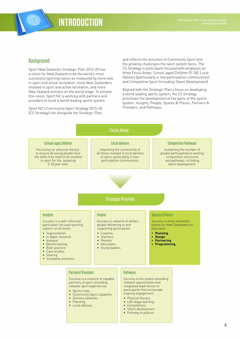
BackgroundSport New Zealand’s Strategic Plan 2015-20 has a vision for New Zealand to be the world’s most successful sporting nation as measured by more kids in sport and active recreation, more New Zealanders involved in sport and active recreation, and more New Zealand winners on the world stage. To achieve this vision, Sport NZ is working with partners and providers to build a world leading sports system.
Sport NZ’s Community Sport Strategy 2015-20 (CS Strategy) sits alongside the Strategic Plan,
and reflects the evolution of Community Sport and the growing challenges the sport system faces. The CS Strategy is participant-focused with emphasis on three Focus Areas: School-aged Children (5-18), Local Delivery (particularly in low participation communities) and Competitive Sport (including Talent Development).
Aligned with the Strategic Plan’s focus on developing a world leading sports system, the CS Strategy prioritises the development of five parts of the sports system: Insights, People, Spaces & Places, Partners & Providers, and Pathways.
School-aged childrenFocussing on ‘physical literacy’ to ensure all young people have
the skills they need to be involved in sport for life, targeting
5-18 year olds.
InsightsSuccess is a well-informed, participant-focused sporting system; at all levels• Segmentation• In depth research• Analysis• Benchmarking• Best-practice• Case studies• Sharing• Innovative solutions
PeopleSuccess is network of skilled people delivering to and supporting participants• Coaches• Teachers• Parents• Volunteers• Young leaders
Spaces & PlacesSuccess is more and better places for New Zealanders to play sport• Planning• Design• Partnering• Programming
Partners/ ProvidersSuccess is a network of capable partners of sport, providing relevant sport experiences• Sports hubs• Community Sport capability• Delivery networks• Planning• Local delivery
PathwaysSuccess is the system providing relevant opportunities and integrated experiences to participants that encourage ongoing engagement• Physical literacy• Life-stage learning• Competitions• Talent development• Pathway to podium
Local deliveryImproving the connectivity of
all those involved in local delivery of sport, particularly in low-participation communities.
Competition PathwaysSustaining the number of
people participating in existing competition structures
and pathways, including talent development.
Focus Areas
Strategic Priorities
6
INTRODUCTION
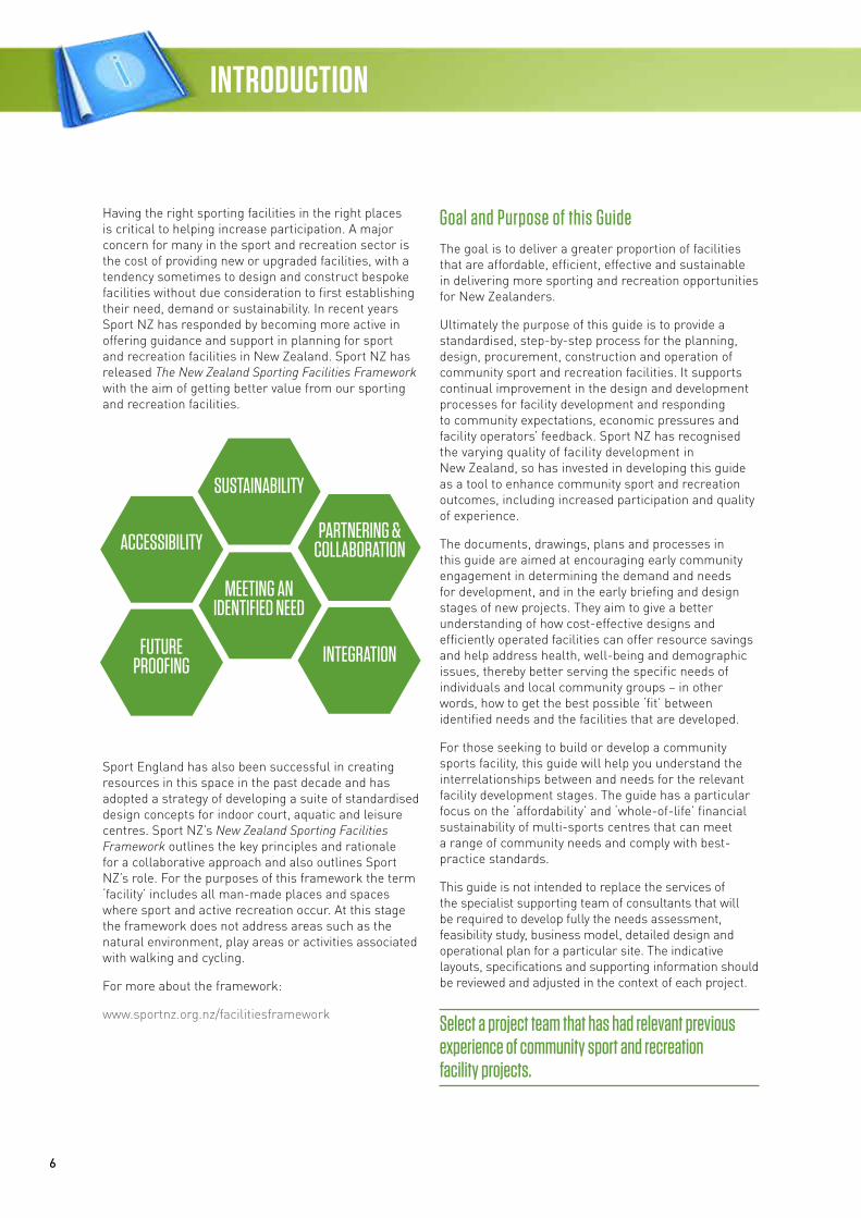
Having the right sporting facilities in the right places is critical to helping increase participation. A major concern for many in the sport and recreation sector is the cost of providing new or upgraded facilities, with a tendency sometimes to design and construct bespoke facilities without due consideration to first establishing their need, demand or sustainability. In recent years Sport NZ has responded by becoming more active in offering guidance and support in planning for sport and recreation facilities in New Zealand. Sport NZ has released The New Zealand Sporting Facilities Framework with the aim of getting better value from our sporting and recreation facilities.
Sport England has also been successful in creating resources in this space in the past decade and has adopted a strategy of developing a suite of standardised design concepts for indoor court, aquatic and leisure centres. Sport NZ’s New Zealand Sporting Facilities Framework outlines the key principles and rationale for a collaborative approach and also outlines Sport NZ’s role. For the purposes of this framework the term ‘facility’ includes all man-made places and spaces where sport and active recreation occur. At this stage the framework does not address areas such as the natural environment, play areas or activities associated with walking and cycling.
For more about the framework:
www.sportnz.org.nz/facilitiesframework
Goal and Purpose of this GuideThe goal is to deliver a greater proportion of facilities that are affordable, efficient, effective and sustainable in delivering more sporting and recreation opportunities for New Zealanders.
Ultimately the purpose of this guide is to provide a standardised, step-by-step process for the planning, design, procurement, construction and operation of community sport and recreation facilities. It supports continual improvement in the design and development processes for facility development and responding to community expectations, economic pressures and facility operators’ feedback. Sport NZ has recognised the varying quality of facility development in New Zealand, so has invested in developing this guide as a tool to enhance community sport and recreation outcomes, including increased participation and quality of experience.
The documents, drawings, plans and processes in this guide are aimed at encouraging early community engagement in determining the demand and needs for development, and in the early briefing and design stages of new projects. They aim to give a better understanding of how cost-effective designs and efficiently operated facilities can offer resource savings and help address health, well-being and demographic issues, thereby better serving the specific needs of individuals and local community groups – in other words, how to get the best possible ‘fit’ between identified needs and the facilities that are developed.
For those seeking to build or develop a community sports facility, this guide will help you understand the interrelationships between and needs for the relevant facility development stages. The guide has a particular focus on the ‘affordability’ and ‘whole-of-life’ financial sustainability of multi-sports centres that can meet a range of community needs and comply with best-practice standards.
This guide is not intended to replace the services of the specialist supporting team of consultants that will be required to develop fully the needs assessment, feasibility study, business model, detailed design and operational plan for a particular site. The indicative layouts, specifications and supporting information should be reviewed and adjusted in the context of each project.
Select a project team that has had relevant previous experience of community sport and recreation facility projects.
SUSTAINABILITY
ACCESSIBILITY
FUTURE PROOFING
MEETING AN IDENTIFIED NEED
PARTNERING & COLLABORATION
INTEGRATION
7
Community Sport & Recreation Facility Development Guide
Acknowledgements
Through Sport NZ’s positive and reciprocal working relationship with Sport England, it was evident that many of Sport England’s resources were relevant and, with some adaptation, could meet the requirements of the New Zealand situation. The emphasis of this guide is on ensuring that the adapted resources (concepts, step-by-step process and supporting technical information) will help enable better decision-making and more fit-for-purpose facility development with the limited financial resources available within our communities.
Sport NZ is committed to supporting local government, sports organisations and other parties in planning, designing, procuring, constructing and operating more affordable sports facilities. Sport England has developed considerable intellectual property in the past decade and has willingly agreed to share this information. These are ‘tightly designed’ concepts that are then tailored by the developer to the specific site. Sport NZ has not set out to emulate the affordable sports facilities guidance information developed and successfully implemented by Sport England. In developing this guide Sport NZ has given consideration to the importance of using this information in a way that can be adapted to New Zealand conditions.
Sport NZ is grateful to and acknowledges the valuable assistance of Sport England and its technical team.
For further information about Sport England’s facilities and planning information:
www.sportengland.org/facilities-planning
Sport NZ also wishes to acknowledge those sport and recreation organisations and individuals who provided feedback on the draft guide as part of the consultation process with the sector.
Specifically, Sport NZ is grateful to the following professionals who were part of the working group and carried out a peer review of the draft guide:
Rob McGee, Auckland Council; David Allan, Global Leisure Group; Julian Todd, Wellington City Council; Paul Tredinnick, Marlborough Lines Stadium 2000; Kiri Pope, Kiri Pope Consulting; Matthew Saunders, Northern Arena; and John Filsell, Christchurch City Council.
8
INTRODUCTION
ApproachThis guide is based on the establishment of a ‘reference facility’ for a stand alone sports hall, swimming pool and combined (wet and dry) sports centre and is based on the principles of the New Zealand Sporting Facilities Framework:
Meeting an Identified Need
The best outcomes are achieved when all of the potential users of the facility are identified and a deep understanding is gained of the range of needs that they will have.
Sustainability – Able to be Maintained a Determined Level of Performance
The whole-of-life costs of the facility should be considered at the outset, including how it is intended that these costs will be met. Often investment up-front in, for example, greater energy efficiency, can deliver financial benefits during the life of the facility.
Affordability
A key driver for the development of this guide is to assist communities to achieve affordable outcomes through informed decision-making about the needs being met by a facility, the right sizing of the facility, the right quality of building and the balancing of up-front capital costs with operational needs (the ‘whole-of-life’ cost). A basic level of functional facility may be all that is needed and warranted.
Partnering and Collaboration
Developing partnerships with those outside the sector – in educational and health, with iwi, and with the private sector – increases the likelihood that a facility will be used to its full potential, maximising the return on investment.
Integration
Experience shows that a very effective way of achieving outcomes is to create multi-use facilities or to co-locate/‘hub’ with other sport and recreation, community, education, retail or transport facilities and infrastructure.
Future-Proofing
The best long-term outcomes are achieved by designing facilities in ways that enable them to be adapted, developed and extended in response to future demands.
Reference Facility
The guide’s approach includes three illustrative models of tightly designed community sport and recreation facilities of differing scales. The three models illustrate differing contexts that influence the facility needed for the catchment population being served and the gap in the regional or local network that will be filled by the facility.
The reference facility designs illustrate the different spaces and accommodation that might be appropriate for new community sport and recreation facilities. The accompanying cost plans, specifications and other technical details show how these impact on the total cost of a project.
The reference facility will need to be adjusted to suit the individual community requirements and adjusted to the physical environment of a particular site. The building approaches and selection of materials illustrated are designed to be economical in the context of a sustainable approach. A range of materials exists and they may be more or less appropriate in particular locations. Options are also indicated for adjusting the footprint and massing of buildings to achieve a desired architectural form or to fit into a larger-scale development, thereby offering flexibility in design form.
The indicative designs are compliant with current industry standards. The accompanying indicative costs, specifications, procurement information and operation plans show how a new community sport and recreation facility can be efficiently delivered.
This guide may appear to focus more on aquatic than other indoor court and fitness components. There are good reasons for this as aquatic facilities are:
• The most costly to build
• The most costly to operate
• The least flexible to change their configuration or convert to other uses if the needs of the community change.
9
Community Sport & Recreation Facility Development Guide
Conditions for Using this GuideWhen referring to any documents and associated attachments hosted within or linked to the Guide pages, sub-pages and appendices of the Sport NZ Community Sport and Recreation Facility Development Guide you should note the following conditions of use:
1. A reliance upon the guidance or use of the content of this information will constitute your acceptance of these conditions.
2. The design guidance and reference facility should be taken to imply the minimum standards required to produce best-practice solutions that are acceptable to your organisation.
3. The documents and any associated drawing material are intended for information only.
4. Amendments, alterations and updates of documents and drawings may take place from time to time and it is recommended that they be reviewed at the time of use to ensure the most up-to-date versions are being referred to.
5. All downloadable information and drawings are intended solely to illustrate how elements of a building can comply with minimum requirements, and should be read in conjunction with any relevant other Sport NZ guidance and all relevant codes of compliance, standards and regulatory requirements. The drawings are not ‘site specific’ and are strictly limited to outline proposals. They are not intended for, and should not be used in conjunction with, the procurement of building work, construction, obtaining statutory approvals or any other services in connection with building works.
6. While every effort has been made to ensure the accuracy of all information contained herein, Sport NZ and its agents, including all parties who have made contributions to any documents or downloadable drawings, shall not be held responsible or liable to any third parties in respect of any loss, damage or costs of any nature arising directly or indirectly from reliance placed on this information without prejudice.
7. The views expressed are not intended to take away or diminish the responsibility of the user to comply with appropriate current or future legislation or standards, and if there are any conflicts between the views expressed in any of Sport NZ’s guidance material and other appropriate current or future legislation, the latter shall take precedence.

Community Sport & Recreation Facility Development Guide / 2016
STAGE 1
11
STAGE 1: CONCEPT Community Sport & Recreation Facility Development Guide
If you look around the country you will see a vast range of indoor aquatic and indoor court facility designs. Many were designed to meet community needs at the time and took little account of future demands and needs. Others were designed to meet the requirements of the highest levels of competition and training, and are under-utilised because they are specialised and not suited to multi-use. Most operate at a net cost to their communities, usually funded by ratepayer subsidies. Therefore it is imperative before any facility is built that a thorough and considered process be undertaken.
New Zealanders need the right facilities in the right places at an affordable capital and operating cost to achieve the various, and sometimes competing, community aspirations and outcomes such as generating greater participation. The success of these facilities requires the clear identification of facility needs, good decision-making, more collaboration and smarter investment by relevant stakeholders and agencies.
A challenge is to understand the desired future state and quantify the ‘needs’ vs the ‘wants’. A sport and recreation group or organisation needs its strategy to articulate what the future users of its facility will look like. What are the demographic changes that will impact on participation and what are the general participation trends? What facilities are in the current network and what gap would be filled by the proposed development strategy? It is very difficult for funders to make these decisions without solid evidence that there is a need for a facility.
Many funders now require groups applying for significant capital grants to submit feasibility studies in their supporting documentation. A group looking to source external funding may be building a new facility, purchasing an existing building or undertaking major renovations.
Access to professional expertise helps organisations to take an impartial look at the current and future needs of their communities, and develop sound project plans and appropriate funding strategies.
One of the biggest issues in facility management is the lack of involvement of facility managers at the design stage. Many issues that affect the operation and management of a facility occur because of a lack of early engagement of operators.
Facility managers are best placed to provide advice at the design phase regarding both design and operational issues, as well as balanced input into user demands and needs.
Companion documents to this guide – the Facility Management Manual and Aquatic Facility Guidelines – can also be found on the Sport NZ website. These provide valuable additional guidance for planning, developing and operating community sport and recreation facilities.
Further information: www.sportnz.org.nz/aquaticfacilityguidelines
www.sportnz.org.nz/facilitymanagementmanual
12
STAGE 1: CONCEPT
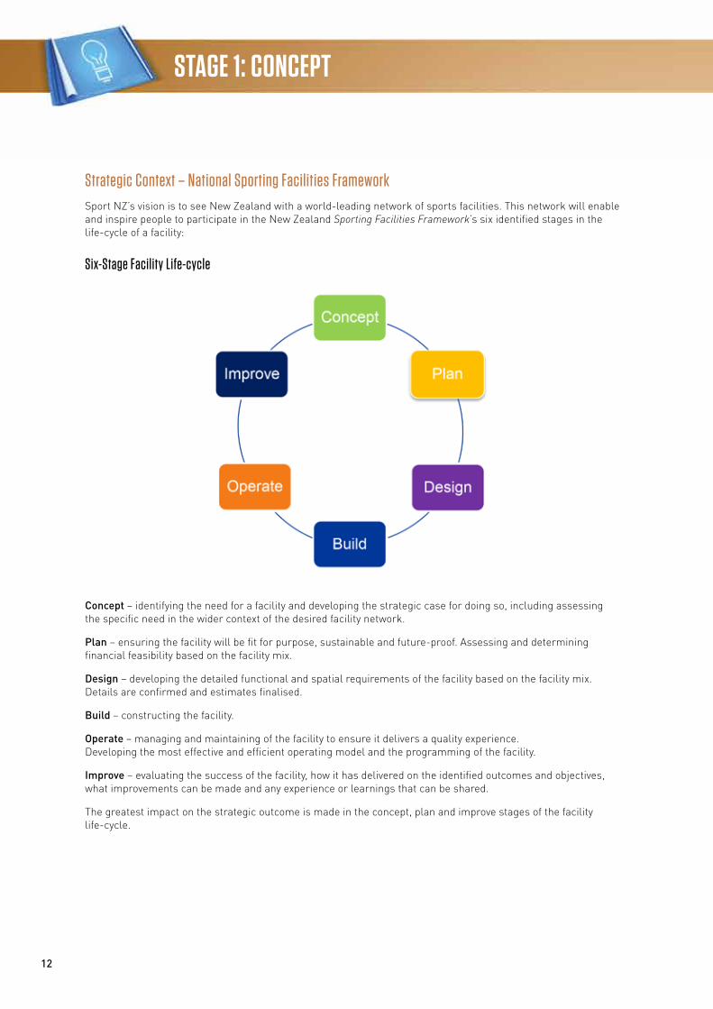
Strategic Context – National Sporting Facilities FrameworkSport NZ’s vision is to see New Zealand with a world-leading network of sports facilities. This network will enable and inspire people to participate in the New Zealand Sporting Facilities Framework’s six identified stages in the life-cycle of a facility:
Six-Stage Facility Life-cycle
Concept – identifying the need for a facility and developing the strategic case for doing so, including assessing the specific need in the wider context of the desired facility network.
Plan – ensuring the facility will be fit for purpose, sustainable and future-proof. Assessing and determining financial feasibility based on the facility mix.
Design – developing the detailed functional and spatial requirements of the facility based on the facility mix. Details are confirmed and estimates finalised.
Build – constructing the facility.
Operate – managing and maintaining of the facility to ensure it delivers a quality experience. Developing the most effective and efficient operating model and the programming of the facility.
Improve – evaluating the success of the facility, how it has delivered on the identified outcomes and objectives, what improvements can be made and any experience or learnings that can be shared.
The greatest impact on the strategic outcome is made in the concept, plan and improve stages of the facility life-cycle.
13
Community Sport & Recreation Facilities Development Guide
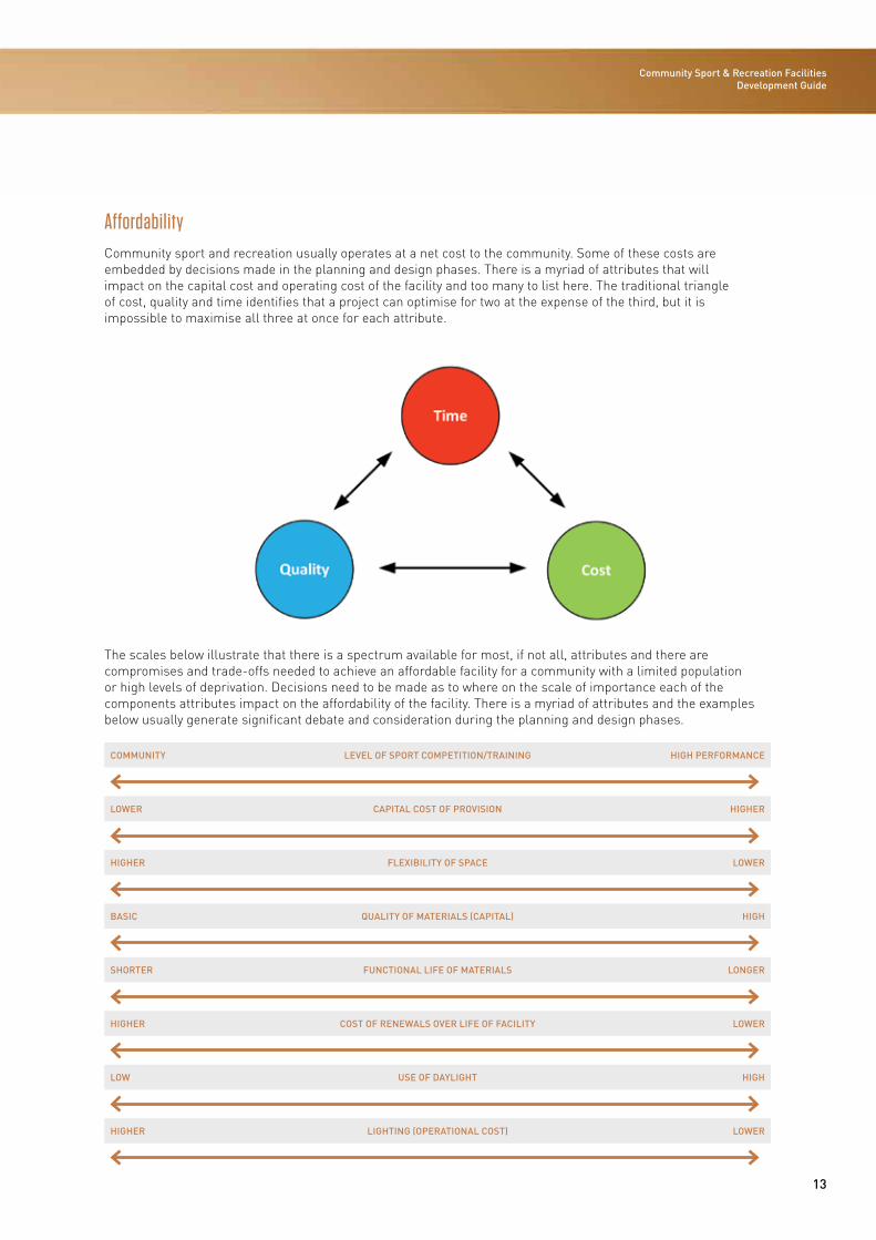
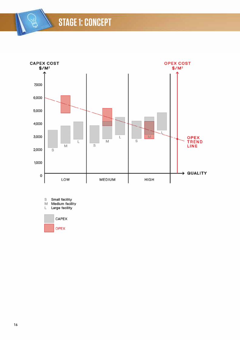
AffordabilityCommunity sport and recreation usually operates at a net cost to the community. Some of these costs are embedded by decisions made in the planning and design phases. There is a myriad of attributes that will impact on the capital cost and operating cost of the facility and too many to list here. The traditional triangle of cost, quality and time identifies that a project can optimise for two at the expense of the third, but it is impossible to maximise all three at once for each attribute.
The scales below illustrate that there is a spectrum available for most, if not all, attributes and there are compromises and trade-offs needed to achieve an affordable facility for a community with a limited population or high levels of deprivation. Decisions need to be made as to where on the scale of importance each of the components attributes impact on the affordability of the facility. There is a myriad of attributes and the examples below usually generate significant debate and consideration during the planning and design phases.
COMMUNITY LEVEL OF SPORT COMPETITION/TRAINING HIGH PERFORMANCE
LOWER CAPITAL COST OF PROVISION HIGHER
HIGHER FLEXIBILITY OF SPACE LOWER
BASIC QUALITY OF MATERIALS (CAPITAL) HIGH
SHORTER FUNCTIONAL LIFE OF MATERIALS LONGER
HIGHER COST OF RENEWALS OVER LIFE OF FACILITY LOWER
LOW USE OF DAYLIGHT HIGH
HIGHER LIGHTING (OPERATIONAL COST) LOWER
14
STAGE 1: CONCEPT
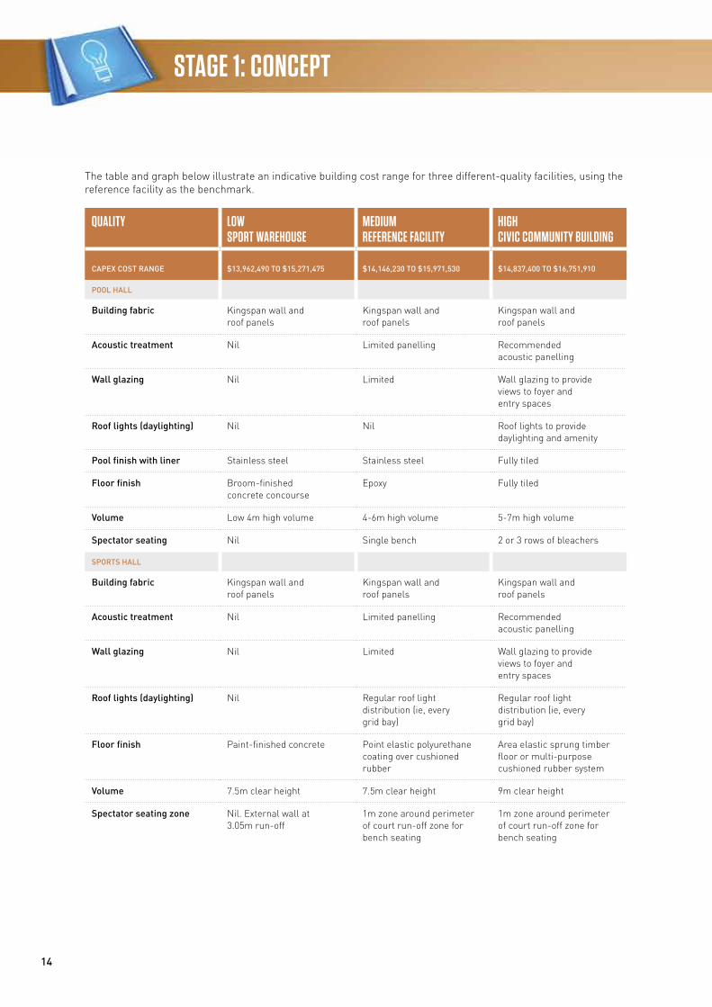
The table and graph below illustrate an indicative building cost range for three different-quality facilities, using the reference facility as the benchmark.
QUALITY LOWSPORT WAREHOUSE
MEDIUMREFERENCE FACILITY
HIGHCIVIC COMMUNITY BUILDING
CAPEX COST RANGE $13,962,490 TO $15,271,475 $14,146,230 TO $15,971,530 $14,837,400 TO $16,751,910
POOL HALL
Building fabric Kingspan wall and roof panels
Kingspan wall and roof panels
Kingspan wall and roof panels
Acoustic treatment Nil Limited panelling Recommended acoustic panelling
Wall glazing Nil Limited Wall glazing to provide views to foyer and entry spaces
Roof lights (daylighting) Nil Nil Roof lights to provide daylighting and amenity
Pool finish with liner Stainless steel Stainless steel Fully tiled
Floor finish Broom-finished concrete concourse
Epoxy Fully tiled
Volume Low 4m high volume 4-6m high volume 5-7m high volume
Spectator seating Nil Single bench 2 or 3 rows of bleachers
SPORTS HALL
Building fabric Kingspan wall and roof panels
Kingspan wall and roof panels
Kingspan wall and roof panels
Acoustic treatment Nil Limited panelling Recommended acoustic panelling
Wall glazing Nil Limited Wall glazing to provide views to foyer and entry spaces
Roof lights (daylighting) Nil Regular roof light distribution (ie, every grid bay)
Regular roof light distribution (ie, every grid bay)
Floor finish Paint-finished concrete Point elastic polyurethane coating over cushioned rubber
Area elastic sprung timber floor or multi-purpose cushioned rubber system
Volume 7.5m clear height 7.5m clear height 9m clear height
Spectator seating zone Nil. External wall at 3.05m run-off
1m zone around perimeter of court run-off zone for bench seating
1m zone around perimeter of court run-off zone for bench seating
15
Community Sport & Recreation Facilities Development Guide
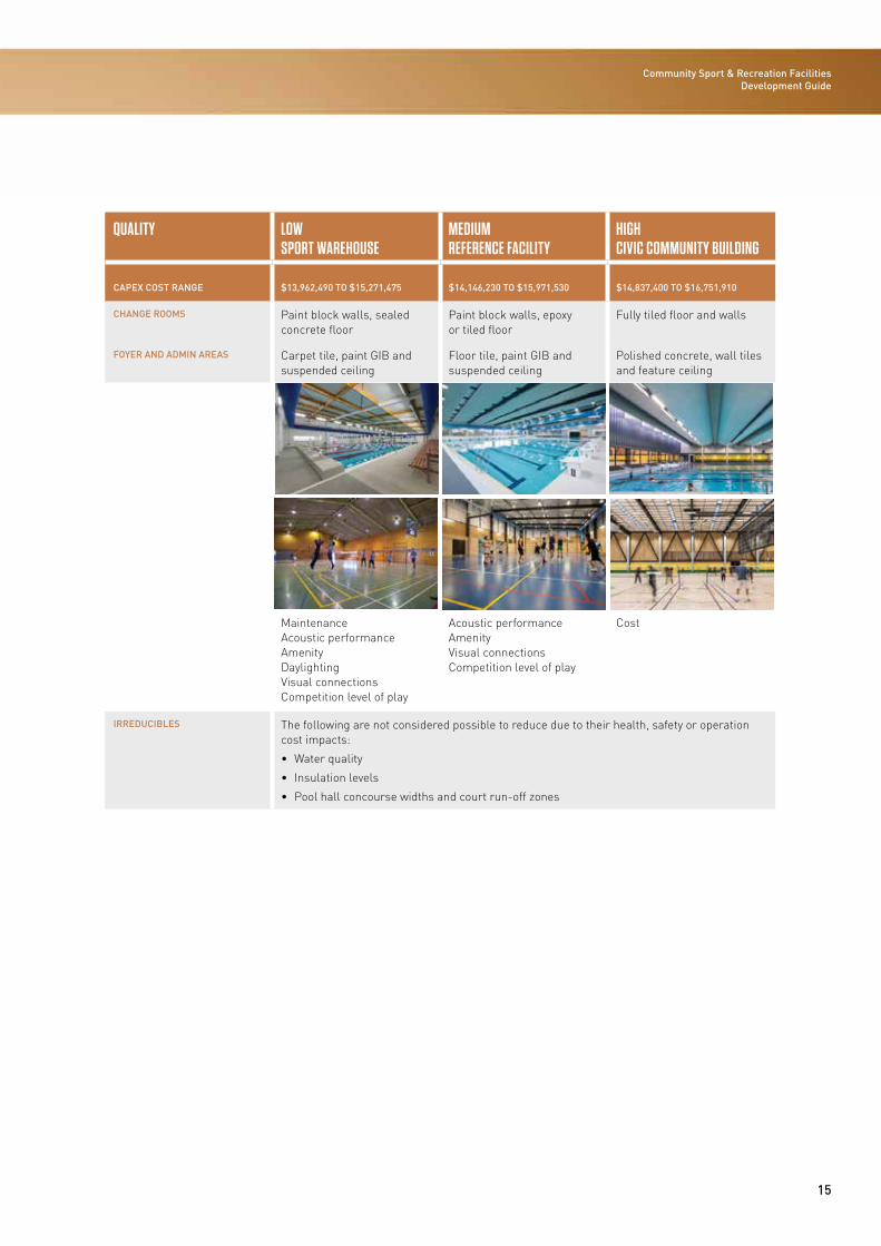
QUALITY LOWSPORT WAREHOUSE
MEDIUMREFERENCE FACILITY
HIGHCIVIC COMMUNITY BUILDING
CAPEX COST RANGE $13,962,490 TO $15,271,475 $14,146,230 TO $15,971,530 $14,837,400 TO $16,751,910
CHANGE ROOMS Paint block walls, sealed concrete floor
Paint block walls, epoxy or tiled floor
Fully tiled floor and walls
FOYER AND ADMIN AREAS Carpet tile, paint GIB and suspended ceiling
Floor tile, paint GIB and suspended ceiling
Polished concrete, wall tiles and feature ceiling
Maintenance Acoustic performance Amenity Daylighting Visual connections Competition level of play
Acoustic performance Amenity Visual connections Competition level of play
Cost
IRREDUCIBLES The following are not considered possible to reduce due to their health, safety or operation cost impacts:
• Water quality
• Insulation levels
• Pool hall concourse widths and court run-off zones
16
STAGE 1: CONCEPT
17
Community Sport & Recreation Facilities Development Guide
Facility Planning ConsiderationsA preliminary task in planning a community sport and recreation facility is its alignment with or inclusion in a wider local or regional strategic sport and recreation plan. A sport and recreation plan identifies existing facilities and services, the broad recreation needs of the community and the action required to meet identified needs. It outlines the priorities for sport and recreation facilities and services, ensuring that provision is equitable and efficient.
Many communities in New Zealand are experiencing population growth, while many others are now in ‘end-of-growth’ mode with static or declining populations for the foreseeable future.
Traditionally, many local authority community sport and recreation facilities have been built for specialist or limited market users (ie, competitive aquatic sports or court sports).
Industry facility trends indicate that revenue rarely meets annual operating costs for the majority of community indoor facilities. To ensure the best financial viability and attract potential interest from other funders or investors, any future facility must be designed with components that have the potential to contribute positive revenue streams and the capacity to be profitable. Positive contributions to operating costs can assist in off-setting the net costs of other components and may help in attracting private commercial investment or services delivery interest.
There is a strong trend of and greater value in the co-location of indoor sport and aquatic facilities with other public or private facilities such as sports parks, retail centres, libraries and community centres so as to create social infrastructure hubs and generate economies of scale.
The ultimate goal is a facility of good quality that meets the expectations of a wide cross-section of its community and has lower operating costs, including those associated with ongoing asset maintenance. Traditionally, our expectation has been that buildings are designed and built for a minimum 50-year life. However, sport and recreation is a highly dynamic sector and it is appropriate to plan for a functionally effective life of 25 years before a major refit or reconfiguration is likely to be required to meet changed community needs. Sound design and detailing will help minimise the operating cost of the facility over its planned life.
Organisations developing aquatic facilities need to consider three distinct user markets:
Recreation and leisure market – (60-70 percent of users) usually made up of families, people coming with friends and groups for fun, relaxation, social activity and low-level competition/participation.
Competitive/training/fitness market – (20-30 percent of users) usually made up of people predominantly attending facilities alone for structured fitness or aquatic sport activities and competition.
Health and therapy market – (10 percent of users) usually made up of older adults and members of specialist health condition groups such as those with arthritis, asthma or mobility conditions. They require water with a higher temperature and facilities associated with health and relaxation, such as spa and hydrotherapy pools.
Research throughout New Zealand and overseas indicates that the recreation and leisure market will continue to be the largest as it contains people of all ages, abilities, types, interests and genders. The competitive/training/fitness area is a more specialist market generally containing younger, fitter and more active people who make time to train and compete.
18
STAGE 1: CONCEPT
Concept
The Facility Planning Process
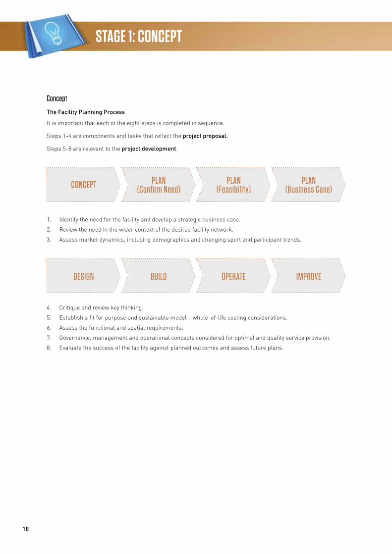
It is important that each of the eight steps is completed in sequence.
Steps 1-4 are components and tasks that reflect the project proposal.
Steps 5-8 are relevant to the project development.
1. Identify the need for the facility and develop a strategic business case.
2. Review the need in the wider context of the desired facility network.
3. Assess market dynamics, including demographics and changing sport and participant trends.
4. Critique and review key thinking.
5. Establish a fit for purpose and sustainable model – whole-of-life costing considerations.
6. Assess the functional and spatial requirements.
7. Governance, management and operational concepts considered for optimal and quality service provision.
8. Evaluate the success of the facility against planned outcomes and assess future plans.
CONCEPT PLAN (Confirm Need)
PLAN (Feasibility)
PLAN (Business Case)
DESIGN BUILD OPERATE IMPROVE
19
Community Sport & Recreation Facilities Development Guide
Overall, the planning and concept development phase should answer the following questions:
• What are the key reasons for developing the facility?
• Who is the facility being built for?
• How do we know it is going to be used by those groups and individuals?
• Are there potential collaborators and partners?
• Is there potential for co-location or integration with other community facilities?
• Where is the best location?
• How is it going to be managed?
• How will the design/construction costs be met?
• How will the ongoing operational and development costs be met?
• How will it remain fit for purpose for the life of the facility?
A three-stage process is recommended, with the ability to review before proceeding to the next stage. The stages are:
1. Initial scoping and brief.
2. Needs assessment.
3. Feasibility.
As a guide, the needs assessment and feasibility stages of the planning process may take up to 5 percent of the total cost of development, but can determine up to 65 percent of the final building cost. They are worth doing, and doing well, in order to minimise future costs and investment.
Getting it right – common errors/assumptions include:
• Poor brief – leading to unclear expectations
• Lack of quality data to inform decisions
• Scope being either too broad or too narrow; not consulting or not getting the right people around the table
• Not having a clear project structure, including a project control group responsible for sign-off of key milestones.
Initial Scoping and Brief
A scoping exercise needs to be undertaken to define and frame the proposition at an outline level.
The scoping will provide the information needed for the preparation of the brief for the needs assessment and the feasibility study; often these two elements are undertaken as one study where there is reasonable certainty regarding the need for a facility. Independent planning consultants with relevant expertise and previous experience with this type of facility usually undertake these studies.
Needs Assessment
It is essential that a needs assessment (sometimes called a pre-feasibility study) be undertaken before embarking on a feasibility study. In short, this involves identifying any lack or over-supply of existing facilities and services. The aim of a needs assessment is to justify provision. It is only when the needs assessment has been completed that a feasibility study can be undertaken to assess the viability of any proposed facility development.
The following section draws from Chapter 4 Strategy and Planning of the Facility Management Manual and Chapter 8 Facility Development of the Aquatic Facility Guidelines developed by the New Zealand Recreation Association (NZRA) and Sport NZ.
A community sport and recreation facility aims to meet the needs of the community at an affordable cost. A facility’s financial sustainability is also linked to how well it services existing and future sport and recreation needs. Initial clarity about the needs of the community that will be met by the facility, and the setting of clear objectives to reflect needs, are key ingredients for success. Understanding needs may involve: defining the facility catchment; undertaking a strategic view of community facilities in the long term in the area; and identifying what role the facility can play in addressing the need. It is important that the drivers for a facility in terms of community needs can be clearly articulated and, where possible, quantified.
A needs assessment identifies any lack or over-supply of existing facilities and services. The aim of the assessment is to prove (or disprove) need through evidence, separating desire from need.
20
STAGE 1: CONCEPT
A thorough assessment of needs is fundamental to the success of the project. For local authorities, there is a statutory obligation to consult the affected community. For other facility developers, it is commercially astute to determine needs before investing significant funds.
The needs assessment would usually involve the following:
• Identify the current supply of facilities and the characteristics of the network (the proximity and functional capabilities and capacity of the other facilities)
• Define the catchment area and population
• Establish the key characteristics of the population
• Define the gap in facility provision
• Identify the current and projected needs for the project
• Establish the priority needs
• Identify options to meet the priority needs (redevelopment, reallocation of space and new facilities should all be considered)
• Refine the objectives of the facility
• Establish the activity and facility mix to meet the needs
• Define likely roles and responsibilities with stakeholders/collaborators/partners
• Identify location options from a strategic perspective
• Identify any parking requirements (refer to district plan)
If the needs assessment confirms there is a need as identified in the initial scoping, the next step is to undertake a feasibility study. In the unusual event that the needs assessment concludes there is no identified need, the feasibility study component would not proceed.
Care should be taken to be guided by real needs, as opposed to expressed wants, to avoid spiralling capital and operating costs that create excessive/unsustainable financial burdens.
Feasibility
It is important to acknowledge the two stages in the feasibility study process. The first stage develops the concept of the facility, while the second stage of the feasibility study tests the practicality of the concept. Ideally the two stages should be undertaken separately by independent parties to ensure impartial judgement and transparent processes.
To determine the meaning of success for the facility, the developer must identify what they want to achieve through their proposed facility. Setting objectives for the facility should also clearly determine the relative commercial and community focuses of the facility. Some facilities may have a greater focus on commercial success, while others may weight delivery on social objectives (social inclusion, health, participation, safety).
A feasibility study will assess the viability of the facility proposal. A good study provides an excellent guide to what will be developed for the capital investment and minimises or eliminates unanticipated surprises during construction and operation.
The feasibility study should:
• Formalise how the facility will meet the needs
• Refine and assess for each option the scope of the facility, technical requirements, costs, strengths, weaknesses, opportunities and threats (SWOT assessment), the potential return on investment, timeframes, resources required, governance and management models, risks and building on the activities and facility mix
• Assess locations for each option for the facility against agreed attributes, including the redevelopment of an existing facility
• Prepare a concept design(s) including preliminary costing
• Define the business case and business model
• Identify who could co-locate and/or partner
• Develop an area schedule of rooms and components for inclusion in the facility design brief.
21
Community Sport & Recreation Facilities Development Guide
Note: investment in a desk-top investigation of likely surface and sub-surface conditions (geotechnical, contaminated ground etc) as part of the site selection process is recommended. Note: the concept design is flexible and will probably change. Do not spend time and money developing and discussing the alternative layouts at this stage. Once the proposal is deemed feasible, and has been approved, it will enter the design phase. It is then that the skills of a professional consultant design team will be utilised to develop a schematic design.
Business Case
In preparing the business case as part of the feasibility study, there are several key steps to include. They are:
• Confirm vision and objectives
• Confirm the purpose of the facility
• Specify the service offering required to meet community needs and ensure alignment with existing strategies and policies (eg, sport and recreation plans)
• Develop high-level concept design
• Undertake community consultation including mana whenua
• Specify the occupancy and throughput model
• Specify the pricing of services
• Generate an operational income and expenditure model over a 10-year period – include any known warranty maintenance cost requirements
• Identify and engage further with stakeholders and the community, potential operators, and seek ongoing feedback on design and operating models
• Define the ownership, governance, management and operating model, including the following:
a. Are other parties able to contribute to capital and/or operating costs?
b. Will the facility or programmes generate and maximise the percentage of use and occupancy?
c. Resourcing – are the right (governance, project management and operational) skills available?
d. Risk – identify and mitigate any ownership, financial, construction and ongoing operational risks
• Set principles for the design of the facility that address functionality, user experience, access and sustainability
• Provide strategy for ongoing asset management
• Identify funding opportunities and sources
• Develop a framework for monitoring and evaluating the project
• Develop an ongoing engagement strategy.
Needs assessment, feasibility and business case are the client’s best insurance against a poor investment!
The Government Treasury website offers guidance on developing better business cases: www.treasury.govt.nz/statesector investmentmanagement/plan/bbc
Peer Review
It is desirable to undertake an independent review/assessment of the feasibility study, especially if considering a large-scale project. The review should be undertaken by an independent person(s) with relevant expertise and experience and should consider:
• Rationale for the proposed facility Is the provision of the proposed facility the best way of meeting the community’s needs for sport and recreation services? Have the merits of other feasible options been objectively considered?
• Practicability of the draft business model Is the proposed approach workable, achievable and cost-effective? Does the business model target the findings of the market analysis?
• Suitability of the concept design and location Does the proposed concept design and site accommodate the activity and facility mix in the best possible way? Within the design, have the most practical and energy-efficient technical systems been chosen? Does the building structure suit the climate?
• Validity of the assumptions/projections included within the business case Are there risks concerning the assumptions upon which the usage and financial projections are based? Is the degree of risk significant? How can the risks be mitigated?
22
STAGE 1: CONCEPT
• Economic, environmental and social viability of the proposal What impact will the proposed facility have on external economic, environmental and social systems? Will the net effect benefit the community?
• Recommendations Are the recommendations supported by the findings of the study?
The NZRA may be able to provide and assist with funding for the peer review of projects. Some criteria, and conditions exist so contact the NZRA for further information: www.nzrecreation.org.nz
Funding Agreements
The purpose of a funding agreement is:
• For organisations that are funding a project, to detail the terms and conditions of the investment, including how the investment may be used
• For parties to agree on other project matters related to the project, well before construction starts.
Where there are multiple funding partners, a funding agreement should be signed by the lead group (facility owner) and each individual funding partner (ie, a separate funding agreement for each organisation that provides funds).
The funding agreement should include what the grant/donation will cover (eg, consultants’ fees, consent fees, technical works, site investigation fees, earthworks, construction, demolition of an old building to make way for a new building, interior fit-out). It is recommended that a cash flow forecast be included in a funding agreement so that each funding organisation knows when a grant payment is due. The cash flow forecast (to which all the funders agree) assists the project manager in budgeting for the project. It is usually prepared by the project manager.
A funding agreement should include a clause stating what funding is required in order for the project to start (eg, all funding required has been raised).
Memorandum of Understanding and/or Terms of Reference
A memorandum of understanding (MoU) provides the best opportunity to determine agreement as how a facility is to be owned and operated. It minimises the risk of misunderstandings or disagreements once the facility is constructed as parties are clearly aware of the roles, responsibilities and costs of operating the facility.
An MoU can be prepared and signed by all parties that will occupy the building. It is recommended that an MoU be signed before a funding agreement is signed.
Further Guidance on Facility Mix and Location
This section provides further information on some key aspects for consideration during the initial scoping, needs assessment and feasibility study phases.
Facility Mix
To develop the preliminary facility mix, first identify the various facility components, ie, the different spaces/functional areas needed within the main structure. Information on what facility components will be the most appropriate can be ascertained from:
• Discussions with proposed users/tenants
• Visits to similar facilities where the community is of a similar size and demographic
• Discussions with facility managers, design consultants and sport or recreation planners and industry bodies (ie, Sport NZ and the NZRA).
Outline the specific components of the facility:
• Describe the primary activity spaces required
• Identify the secondary and support areas to be accommodated, ie, carpark, viewing areas, reception/foyer areas, ablutions, café, sports shop, kitchen, crèche, operational plant rooms and equipment storerooms etc
• Define the functional requirements of each area, ie, rough dimensions and capacity requirements (based on estimated usage), major items of furniture and equipment to be accommodated, types of floor surface, storage space requirements and mechanical services etc
• Define the important interrelationships between activity areas and indicate where activity areas need to be adjacent (consider flow of internal traffic, supervision requirements and potential for multi-skilling of staff).
Bubble diagrams may be used to provide a graphic illustration. The above information should provide sufficient detail to enable a cost planner/quantity surveyor to estimate the ‘ballpark’ capital cost of the proposal.
23
Community Sport & Recreation Facilities Development Guide
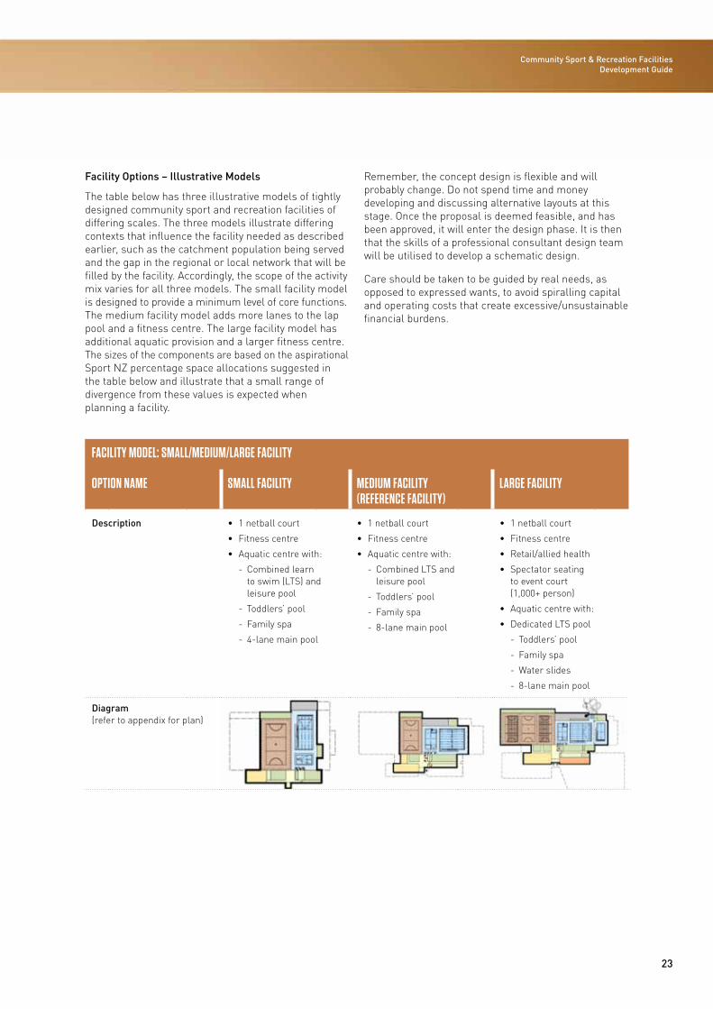
Facility Options – Illustrative Models
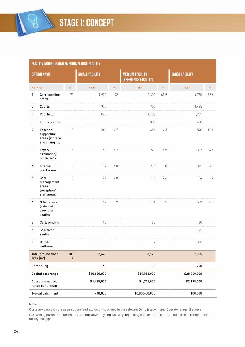
The table below has three illustrative models of tightly designed community sport and recreation facilities of differing scales. The three models illustrate differing contexts that influence the facility needed as described earlier, such as the catchment population being served and the gap in the regional or local network that will be filled by the facility. Accordingly, the scope of the activity mix varies for all three models. The small facility model is designed to provide a minimum level of core functions. The medium facility model adds more lanes to the lap pool and a fitness centre. The large facility model has additional aquatic provision and a larger fitness centre. The sizes of the components are based on the aspirational Sport NZ percentage space allocations suggested in the table below and illustrate that a small range of divergence from these values is expected when planning a facility.
Remember, the concept design is flexible and will probably change. Do not spend time and money developing and discussing alternative layouts at this stage. Once the proposal is deemed feasible, and has been approved, it will enter the design phase. It is then that the skills of a professional consultant design team will be utilised to develop a schematic design.
Care should be taken to be guided by real needs, as opposed to expressed wants, to avoid spiralling capital and operating costs that create excessive/unsustainable financial burdens.
FACILITY MODEL: SMALL/MEDIUM/LARGE FACILITY
OPTION NAME SMALL FACILITY MEDIUM FACILITY (REFERENCE FACILITY)
LARGE FACILITY
Description • 1 netball court
• Fitness centre
• Aquatic centre with:
- Combined learn to swim (LTS) and leisure pool
- Toddlers’ pool
- Family spa
- 4-lane main pool
• 1 netball court
• Fitness centre
• Aquatic centre with:
- Combined LTS and leisure pool
- Toddlers’ pool
- Family spa
- 8-lane main pool
• 1 netball court
• Fitness centre
• Retail/allied health
• Spectator seating to event court (1,000+ person)
• Aquatic centre with:
• Dedicated LTS pool
- Toddlers’ pool
- Family spa
- Water slides
- 8-lane main pool
Diagram (refer to appendix for plan)
24
STAGE 1: CONCEPT
FACILITY MODEL: SMALL/MEDIUM/LARGE FACILITY
OPTION NAME SMALL FACILITY MEDIUM FACILITY (REFERENCE FACILITY)
LARGE FACILITY
METRICS % AREA % AREA % AREA %
1 Core sporting areas
70 1,920 72 2,600 69.9 4,780 67.6
a Courts 900 900 2,425
b Pool hall 870 1,400 1,905
c Fitness centre 150 300 450
2 Essential supporting areas (storage and changing)
13 340 12.7 456 12.3 890 12.6
3 Foyer/ circulation/ public WCs
6 152 5.7 220 5.9 327 4.6
4 Internal plant areas
5 132 4.8 215 5.8 345 4.9
5 Core management areas (reception/ staff areas)
3 77 2.8 98 2.6 134 2
6 Other areas (café and spectator seating)
3 49 2 131 3.5 589 8.3
a Café/vending 15 60 60
b Spectator seating
0 0 145
c Retail/ wellness
0 7 305
Total ground floor area (m2)
100 %
2,670 3,720 7,065
Carparking 50 100 200
Capital cost range $10,680,000 $15,953,000 $28,260,000
Operating net cost range per annum
$1,465,000 $1,711,000 $2,195,000
Typical catchment <10,000 10,000-50,000 >100,000
Notes:
Costs are based on the assumptions and exclusions outlined in the relevant Build (stage 4) and Operate (stage 5) stages.
Carparking number requirements are indicative only and will vary depending on site location, local council requirements and facility mix type.
25
Community Sport & Recreation Facilities Development Guide
The facility mix is used to develop an area schedule that should be included in the facility design brief when procuring a consultant team.
Location Rationale
Consider whether existing facilities could be extended or upgraded for use on a shared basis.
If this is not possible and a new facility is required, you should plan, in consultation with other facility providers, to ensure minimum duplication and maximum use of resources.
Consider the possibility of co-locating the proposed facility with other community or commercial facilities. If properly integrated, this approach can work to create a ‘hub’ within your community, centralising facilities in a village concept. Co-location with other major providers will maximise service and social outcomes and provide opportunities to reduce capital and operating costs.
Discuss your proposal with the Ministry of Education and local schools and/or tertiary education facilities, local sports groups, commercial organisations, and neighbouring local and regional authorities to explore opportunities to co-locate and share the provision and/or use of facilities.
Site Suitability
Usually location, availability and cost will dictate the choice of site. However, when looking at a site for a sport and recreation facility, considerations include:
• Zoning regulations and local authority planning rules and restrictions
• Ownership of the land and cost to purchase or lease the site
• Historical value or heritage significance
• Any bearing on Treaty of Waitangi settlement legislation or issues of importance to Ma-ori
• Accessibility for pedestrians, cyclists, motor vehicles and public transport
• Visibility of site
• Social impact – opportunities for integration with community and commercial facilities
• Proximity to the catchment area and potential user groups
• Size – provision for carparking and potential for future expansion of facility or addition of other facilities
• Existing structures and their usage
• Surface and sub-surface conditions (geotechnical, contaminated ground)
• Environmental considerations.
Space Allocations
Sport NZ has undertaken some benchmarking analysis of the percentage of floor area devoted to the various essential functions in community sport and recreation facilities in New Zealand. The allocations in the table below have been informed by the benchmark exercise of existing sports facilities in this country, balanced with aspirations to improve the function and affordability of these facilities. Refer to Stage 6 Improve for details on the benchmarking.
The percentage allocations below are designed to inform the proportion of core sport and recreation, support, circulation, plant and staff accommodation areas. These allocations are indicative only and should be used to test the facility brief and area schedule. The allocations are intended to be used as an aspirational guide. A specific design of a facility is required using the needs analysis and design guidance (Design section) and relevant New Zealand standards, the New Zealand Building Code and best-practice notes to fully inform a facility brief area schedule.
The guideline percentages in the table below reflect the aspiration to maximise the area allocated for sport and recreation activities in a tightly-designed facility. However, it is critical to understand that a sufficiency of allocation for supporting areas such as storage will impact on the operational effectiveness and efficiency of the facility.
26
STAGE 1: CONCEPT
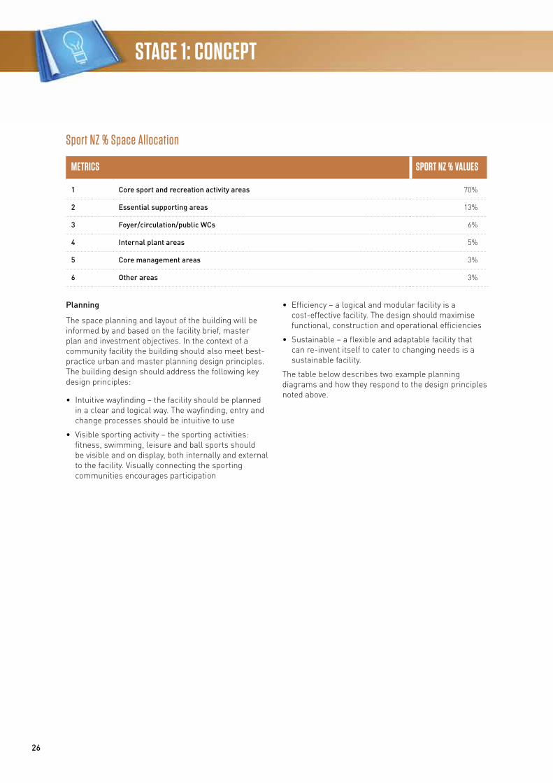
Sport NZ % Space Allocation
METRICS SPORT NZ % VALUES
1 Core sport and recreation activity areas 70%
2 Essential supporting areas 13%
3 Foyer/circulation/public WCs 6%
4 Internal plant areas 5%
5 Core management areas 3%
6 Other areas 3%
Planning
The space planning and layout of the building will be informed by and based on the facility brief, master plan and investment objectives. In the context of a community facility the building should also meet best-practice urban and master planning design principles. The building design should address the following key design principles:
• Intuitive wayfinding – the facility should be planned in a clear and logical way. The wayfinding, entry and change processes should be intuitive to use
• Visible sporting activity – the sporting activities: fitness, swimming, leisure and ball sports should be visible and on display, both internally and external to the facility. Visually connecting the sporting communities encourages participation
• Efficiency – a logical and modular facility is a cost-effective facility. The design should maximise functional, construction and operational efficiencies
• Sustainable – a flexible and adaptable facility that can re-invent itself to cater to changing needs is a sustainable facility.
The table below describes two example planning diagrams and how they respond to the design principles noted above.
27
Community Sport & Recreation Facilities Development Guide
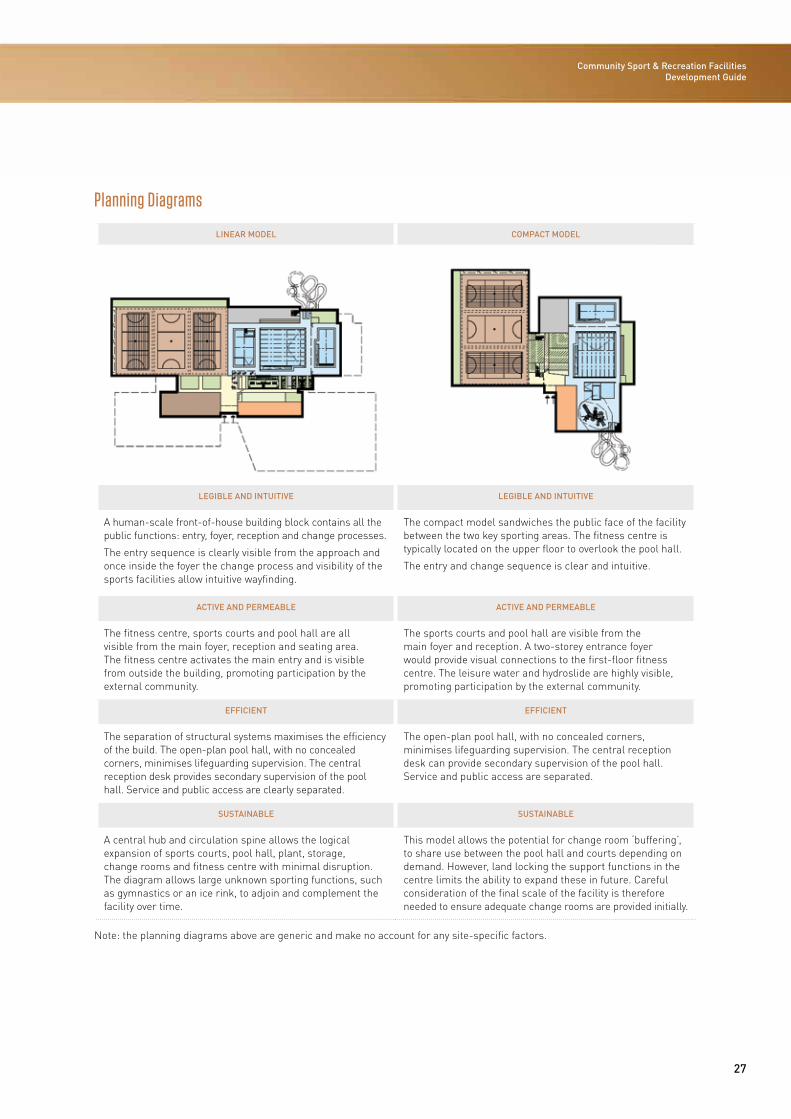
Planning Diagrams
LINEAR MODEL COMPACT MODEL
LEGIBLE AND INTUITIVE LEGIBLE AND INTUITIVE
A human-scale front-of-house building block contains all the public functions: entry, foyer, reception and change processes.
The entry sequence is clearly visible from the approach and once inside the foyer the change process and visibility of the sports facilities allow intuitive wayfinding.
The compact model sandwiches the public face of the facility between the two key sporting areas. The fitness centre is typically located on the upper floor to overlook the pool hall.
The entry and change sequence is clear and intuitive.
ACTIVE AND PERMEABLE ACTIVE AND PERMEABLE
The fitness centre, sports courts and pool hall are all visible from the main foyer, reception and seating area. The fitness centre activates the main entry and is visible from outside the building, promoting participation by the external community.
The sports courts and pool hall are visible from the main foyer and reception. A two-storey entrance foyer would provide visual connections to the first-floor fitness centre. The leisure water and hydroslide are highly visible, promoting participation by the external community.
EFFICIENT EFFICIENT
The separation of structural systems maximises the efficiency of the build. The open-plan pool hall, with no concealed corners, minimises lifeguarding supervision. The central reception desk provides secondary supervision of the pool hall. Service and public access are clearly separated.
The open-plan pool hall, with no concealed corners, minimises lifeguarding supervision. The central reception desk can provide secondary supervision of the pool hall. Service and public access are separated.
SUSTAINABLE SUSTAINABLE
A central hub and circulation spine allows the logical expansion of sports courts, pool hall, plant, storage, change rooms and fitness centre with minimal disruption. The diagram allows large unknown sporting functions, such as gymnastics or an ice rink, to adjoin and complement the facility over time.
This model allows the potential for change room ‘buffering’, to share use between the pool hall and courts depending on demand. However, land locking the support functions in the centre limits the ability to expand these in future. Careful consideration of the final scale of the facility is therefore needed to ensure adequate change rooms are provided initially.
Note: the planning diagrams above are generic and make no account for any site-specific factors.
28
STAGE 1: CONCEPT
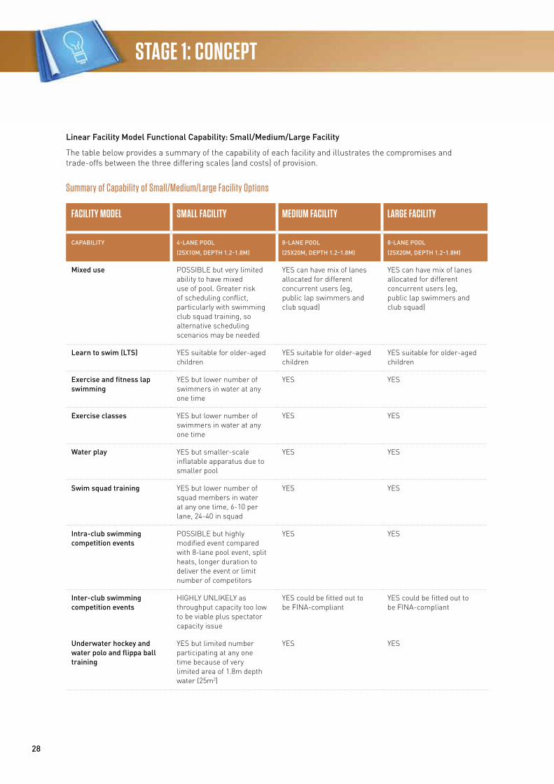
Linear Facility Model Functional Capability: Small/Medium/Large Facility
The table below provides a summary of the capability of each facility and illustrates the compromises and trade-offs between the three differing scales (and costs) of provision.
Summary of Capability of Small/Medium/Large Facility Options
FACILITY MODEL SMALL FACILITY MEDIUM FACILITY LARGE FACILITY
CAPABILITY 4-LANE POOL
(25X10M, DEPTH 1.2-1.8M)
8-LANE POOL
(25X20M, DEPTH 1.2-1.8M)
8-LANE POOL
(25X20M, DEPTH 1.2-1.8M)
Mixed use POSSIBLE but very limited ability to have mixed use of pool. Greater risk of scheduling conflict, particularly with swimming club squad training, so alternative scheduling scenarios may be needed
YES can have mix of lanes allocated for different concurrent users (eg, public lap swimmers and club squad)
YES can have mix of lanes allocated for different concurrent users (eg, public lap swimmers and club squad)
Learn to swim (LTS) YES suitable for older-aged children
YES suitable for older-aged children
YES suitable for older-aged children
Exercise and fitness lap swimming
YES but lower number of swimmers in water at any one time
YES YES
Exercise classes YES but lower number of swimmers in water at any one time
YES YES
Water play YES but smaller-scale inflatable apparatus due to smaller pool
YES YES
Swim squad training YES but lower number of squad members in water at any one time, 6-10 per lane, 24-40 in squad
YES YES
Intra-club swimming competition events
POSSIBLE but highly modified event compared with 8-lane pool event, split heats, longer duration to deliver the event or limit number of competitors
YES YES
Inter-club swimming competition events
HIGHLY UNLIKELY as throughput capacity too low to be viable plus spectator capacity issue
YES could be fitted out to be FINA-compliant
YES could be fitted out to be FINA-compliant
Underwater hockey and water polo and flippa ball training
YES but limited number participating at any one time because of very limited area of 1.8m depth water (25m2)
YES YES
29
Community Sport & Recreation Facilities Development Guide
FACILITY MODEL SMALL FACILITY MEDIUM FACILITY LARGE FACILITY
CAPABILITY 4-LANE POOL
(25X10M, DEPTH 1.2-1.8M)
8-LANE POOL
(25X20M, DEPTH 1.2-1.8M)
8-LANE POOL
(25X20M, DEPTH 1.2-1.8M)
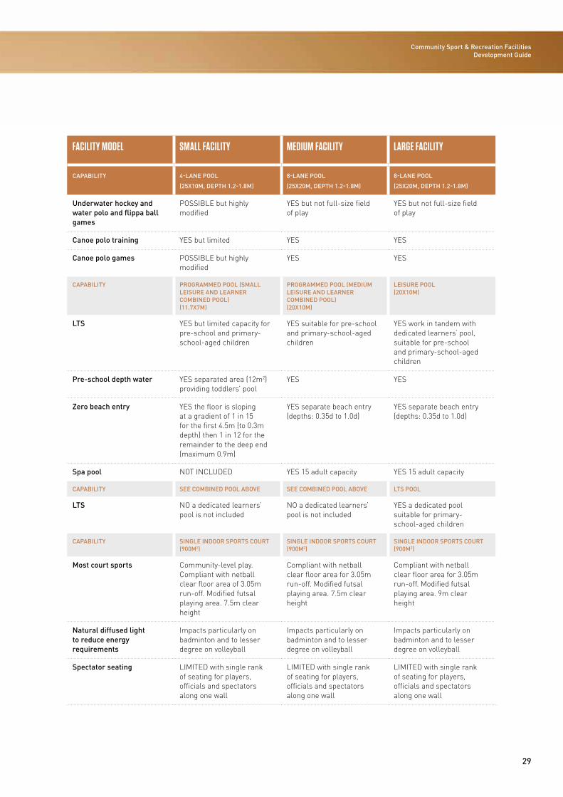
Underwater hockey and water polo and flippa ball games
POSSIBLE but highly modified
YES but not full-size field of play
YES but not full-size field of play
Canoe polo training YES but limited YES YES
Canoe polo games POSSIBLE but highly modified
YES YES
CAPABILITY PROGRAMMED POOL (SMALL LEISURE AND LEARNER COMBINED POOL) (11.7X7M)
PROGRAMMED POOL (MEDIUM LEISURE AND LEARNER COMBINED POOL) (20X10M)
LEISURE POOL (20X10M)
LTS YES but limited capacity for pre-school and primary-school-aged children
YES suitable for pre-school and primary-school-aged children
YES work in tandem with dedicated learners’ pool, suitable for pre-school and primary-school-aged children
Pre-school depth water YES separated area (12m2) providing toddlers’ pool
YES YES
Zero beach entry YES the floor is sloping at a gradient of 1 in 15 for the first 4.5m (to 0.3m depth) then 1 in 12 for the remainder to the deep end (maximum 0.9m)
YES separate beach entry (depths: 0.35d to 1.0d)
YES separate beach entry (depths: 0.35d to 1.0d)
Spa pool NOT INCLUDED YES 15 adult capacity YES 15 adult capacity
CAPABILITY SEE COMBINED POOL ABOVE SEE COMBINED POOL ABOVE LTS POOL
LTS NO a dedicated learners’ pool is not included
NO a dedicated learners’ pool is not included
YES a dedicated pool suitable for primary-school-aged children
CAPABILITY SINGLE INDOOR SPORTS COURT (900M2)
SINGLE INDOOR SPORTS COURT (900M2)
SINGLE INDOOR SPORTS COURT (900M2)
Most court sports Community-level play. Compliant with netball clear floor area of 3.05m run-off. Modified futsal playing area. 7.5m clear height
Compliant with netball clear floor area for 3.05m run-off. Modified futsal playing area. 7.5m clear height
Compliant with netball clear floor area for 3.05m run-off. Modified futsal playing area. 9m clear height
Natural diffused light to reduce energy requirements
Impacts particularly on badminton and to lesser degree on volleyball
Impacts particularly on badminton and to lesser degree on volleyball
Impacts particularly on badminton and to lesser degree on volleyball
Spectator seating LIMITED with single rank of seating for players, officials and spectators along one wall
LIMITED with single rank of seating for players, officials and spectators along one wall
LIMITED with single rank of seating for players, officials and spectators along one wall
30
STAGE 1: CONCEPT
FACILITY MODEL SMALL FACILITY MEDIUM FACILITY LARGE FACILITY
CAPABILITY 4-LANE POOL
(25X10M, DEPTH 1.2-1.8M)
8-LANE POOL
(25X20M, DEPTH 1.2-1.8M)
8-LANE POOL
(25X20M, DEPTH 1.2-1.8M)
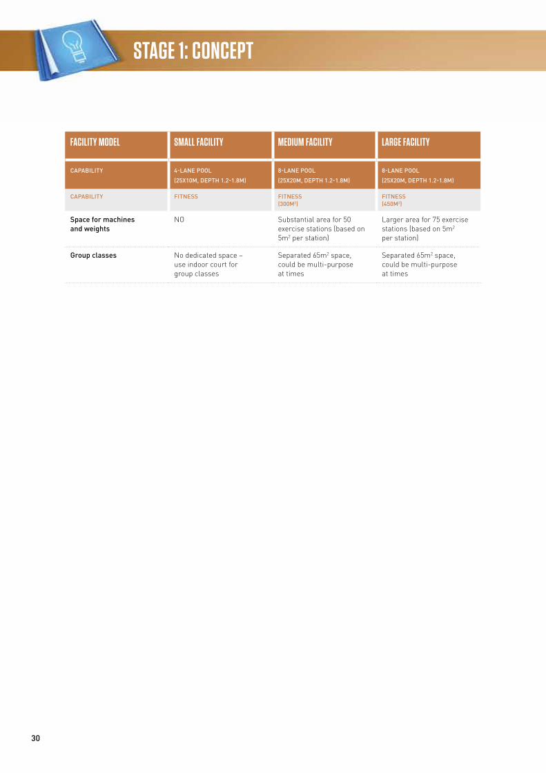
CAPABILITY FITNESS FITNESS (300M2)
FITNESS (450M2)
Space for machines and weights
NO Substantial area for 50 exercise stations (based on 5m2 per station)
Larger area for 75 exercise stations (based on 5m2 per station)
Group classes No dedicated space – use indoor court for group classes
Separated 65m2 space, could be multi-purpose at times
Separated 65m2 space, could be multi-purpose at times
31
Community Sport & Recreation Facilities Development Guide
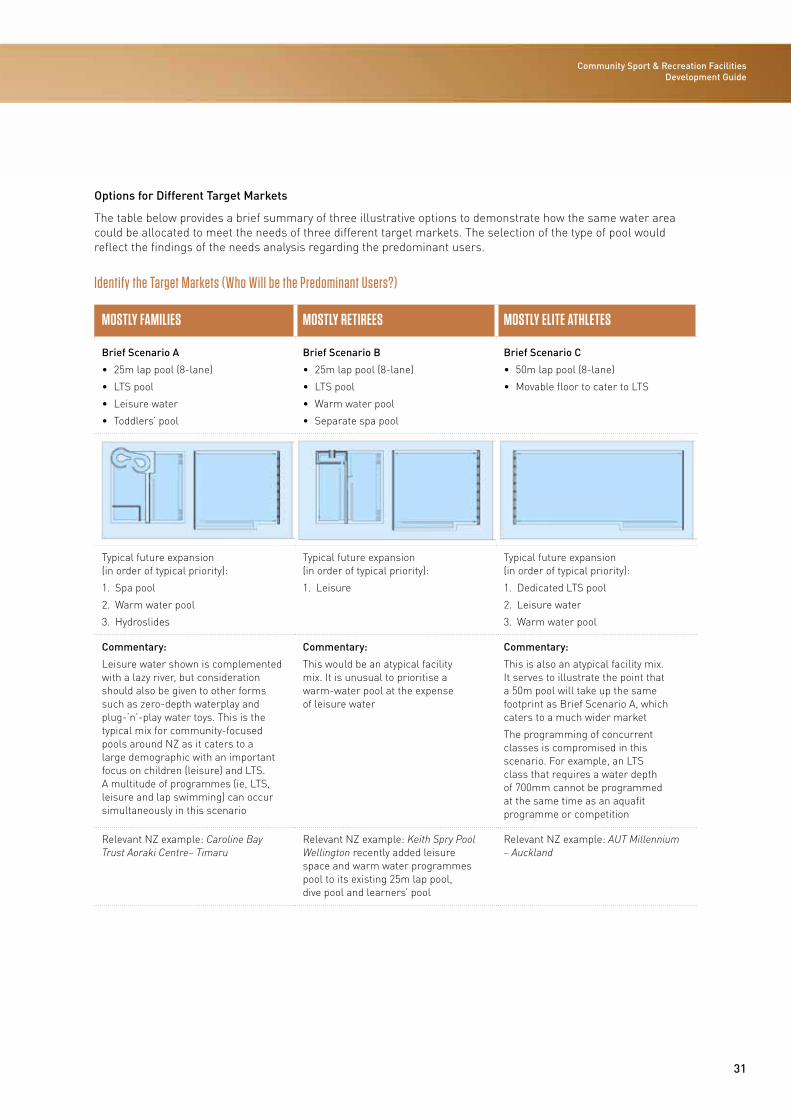
Options for Different Target Markets
The table below provides a brief summary of three illustrative options to demonstrate how the same water area could be allocated to meet the needs of three different target markets. The selection of the type of pool would reflect the findings of the needs analysis regarding the predominant users.
Identify the Target Markets (Who Will be the Predominant Users?)
MOSTLY FAMILIES MOSTLY RETIREES MOSTLY ELITE ATHLETES
Brief Scenario A
• 25m lap pool (8-lane)
• LTS pool
• Leisure water
• Toddlers’ pool
Brief Scenario B
• 25m lap pool (8-lane)
• LTS pool
• Warm water pool
• Separate spa pool
Brief Scenario C
• 50m lap pool (8-lane)
• Movable floor to cater to LTS
Typical future expansion (in order of typical priority):
1. Spa pool
2. Warm water pool
3. Hydroslides
Typical future expansion (in order of typical priority):
1. Leisure
Typical future expansion (in order of typical priority):
1. Dedicated LTS pool
2. Leisure water
3. Warm water pool
Commentary:
Leisure water shown is complemented with a lazy river, but consideration should also be given to other forms such as zero-depth waterplay and plug-’n’-play water toys. This is the typical mix for community-focused pools around NZ as it caters to a large demographic with an important focus on children (leisure) and LTS. A multitude of programmes (ie, LTS, leisure and lap swimming) can occur simultaneously in this scenario
Commentary:
This would be an atypical facility mix. It is unusual to prioritise a warm-water pool at the expense of leisure water
Commentary:
This is also an atypical facility mix. It serves to illustrate the point that a 50m pool will take up the same footprint as Brief Scenario A, which caters to a much wider market
The programming of concurrent classes is compromised in this scenario. For example, an LTS class that requires a water depth of 700mm cannot be programmed at the same time as an aquafit programme or competition
Relevant NZ example: Caroline Bay Trust Aoraki Centre– Timaru
Relevant NZ example: Keith Spry Pool Wellington recently added leisure space and warm water programmes pool to its existing 25m lap pool, dive pool and learners’ pool
Relevant NZ example: AUT Millennium – Auckland
Community Sport & Recreation Facility Development Guide / 2016
STAGE 2
33
STAGE 2: PLAN Community Sport & Recreation Facility Development Guide
IntroductionOnce it has been determined that there is a need for a sports facility, the proposed or preferred mix and components within the facility has been agreed, a viable business case has been developed and a suitable location has been selected, the next step is to start detailed planning for the project. At this stage there are generally further questions that need to be answered, including:
• What are we trying to do?
• Are there any planning restrictions for the proposed site?
• When will we start?
• What do we need?
• Can we do it alone, or do we need help?
• How long will it take?
• How much will it cost?
A successful project is one that has been planned properly and has had strong project management by an experienced person. Structured project management means managing the project in a logical, organised way, following defined steps.
It is essential that someone is responsible for organising and controlling the project. This person is called the project manager and can be either an internal or external resource. Either way, this person needs to have sufficient experience to perform the task professionally, efficiently and effectively.
The project manager will be responsible for selecting people to do the work on the project and ensuring the work is done properly and on time. This person will prepare the project plans that describe what the project team will actually be doing and when they expect to finish.
Design BriefA facility design brief is a scoping document whose purpose is to describe the client’s requirements for the development of a built asset. It is required to communicate to the consultant design team the values, investment objectives, quality and vision of the facility.
It is important to refine and capture the information and decisions that have been made during the initial concept and plan stages of the project so that they can be communicated effectively and concisely to the designers. The design brief is a live document that will be developed, refined and tested by the design team during the design process in consultation with the client.
The project brief is the key document upon which the design will be based. It will evolve through the project brief stage and the concept design stage, with the benefit of information gained from consultation with the client and other stakeholders and ongoing design development. The preparation of the project brief is likely to be coordinated by the lead consultant. It may be developed based on:
• Existing information such as the business case, investment objectives and needs analysis
• Site surveys, site information and site appraisals
• An analysis of existing accommodation
• Workshops with champions and user panels to establish needs, expectations and priorities
• Input from other stakeholders
• A wider consultation process
• Interviews
• User surveys
• Input from statutory authorities such as the fire service, statutory utilities, local authority and heritage organisations.
The project brief is developed from the investment objectives and needs analysis and should describe and quantify the following aspects of the facility:
• A description of the client:
• The client’s brand, culture and organisation
- The client’s vision, mission and objectives
- The client’s priorities and the criteria that will be used to measure success
- The client’s organisational structure and decision-making processes
34
STAGE 2: PLAN
- Changes to the client’s operation that the project will bring about
- Interfaces with other projects
- Client policies that may be applicable to the project (eg, transport policy, energy policy, natural ventilation policy, sustainability policy)
- Client preferences for the project (eg, image, use of local materials, use of landscape) and quality expectations (including health and safety (H&S), sustainability and design quality)
• A description of the principles that will be adopted in the development of the design
• Site information
• Building surveys
• Site surveys
• Information about ground conditions
• The location and capacity of utilities
• Access and other constraints
• Legislative constraints
• Existing planning consents
• Spatial requirements:
- Schedules of accommodation areas and special requirements
- Schedules of users (including external users) and their numbers, departments, functions, organisational structure and operational characteristics
- Spatial policies (eg, open-plan or cellular offices, daylighting requirements, temperature ranges and acoustic standards)
- Required adjacencies, groupings and separations
- Zoning
- Circulation guidelines and major circulation flows
- Phasing
• Technical requirements:
- Structural strategy (columns and gridlines to be adopted, special loads, floor-to-ceiling heights)
- Servicing requirements, including specialist requirements
- Comfort conditions and levels of user control
- Acoustic requirements
- Equipment requirements
- Specialist requirements for furniture, finishes, fixtures and fittings
- Information and communications technology (ICT) requirements
- Requirements for specialist processes and plant
- Fire compartments
- Maintenance and cleaning requirements
- Likelihood of future change (eg, staff numbers) and flexibility required
- Sustainability objectives and energy use targets
- Safety and security requirements
- Resilience to potential hazards and threats
- Waste and water management
- Pollution control
- Flexibility and future uses
- Durability and lifespan
- Other performance requirements
- Benchmarking information
• Component requirements:
- Long-lead items
- Potential requirement for specialist design or specialist contractor design
- Cladding strategy and material selection procedures
• Project requirements and other issues
• Planning requirements:
- Outcome of any consultation processes
- Budget
- Project programme and key milestones
- Known risks
- Targets for post-occupancy evaluation (POE) outcomes and other performance targets.
The project brief will become increasingly detailed throughout the project brief and concept design stages, and may ultimately include very specific information such as data for each room.
The project brief should be frozen at the end of the concept design stage, and change control procedures introduced to prevent further changes without appropriate justification and authorisation.
The project brief is likely to be presented as a report. However, where possible, information and requirements should be scheduled in a database or spreadsheet format that will be easy to expand and easy to use to test whether proposals satisfy requirements later in the project.
35
Community Sport & Recreation Facility Development Guide
ProcurementIntroduction
The procurement strategy considers the procurement options for community sport and recreation facilities through design, construction and operation to deliver affordable solutions.
It is considered best-practice for public sector clients to use approved procurement frameworks. Approved frameworks can significantly reduce the time taken to select and appoint the consultant team.
The choice of procurement route is critical to the success of any construction project. Every project has unique requirements and therefore all viable procurement options need to be appraised at the beginning of the project.
A crucial role in the procurement process will be the senior responsible owner (SRO). This person will require adequate authority to approve the steps of procurement.
The business case should define the investment objectives of the project. Specifically defined project objectives should align with these investment goals and the strategy of the holistic project. For local government agencies, this should align with the better business case model.
Guiding policies and frameworks should be outlined in the business case development.
There are a variety of methods for tendering, which include open, pre-selected, closed, negotiated and sole-source tendering.
The contracting type establishes the framework for the life-cycle delivery of the project. There are several delivery models available, which represent varying degrees of complexity, risk, innovation, client involvement and programme influence.
Consultants can be selected by tender or from an existing panel, which will be based on pre-established criteria. Typical selection criteria include the previous experience of the company and people in the design of facilities, as well as price. These criteria will be weighted based on certain sub-criteria.
Contractors are selected through tendering, and excluded against key performance indicators (KPIs) that encourage them to do a good job and treat the contract as repeat business. Local authorities may have their own contractor frameworks in place. It is important, however, that the contractors who are on a framework have suitable experience.
Some contract frameworks provide an opportunity to involve a contractor earlier in the design process and this should also be considered during the procurement review process.
A ‘design, build, operate and maintain’ contractor will be typically selected based on a minimum period of 15 years, while externally contracted facility operators will usually have a duration of 10 years with the possibility of a five-year extension.
The contract form will typically be a single contract, but there may be scenarios where multiple contracts or a management contract are better suited.
Payment mechanisms will typically be lump sum, but measure and value, cost reimbursement or a combination of payment types may also be suitable.
Specialist procurement input from the project manager, architect or quantity surveyor should be sought in the decision-making process.
Procurement Strategy
The procurement strategy defines the procurement process for the project. This may be prepared internally of externally (project manager or architect).
It is recommended that the procurement strategy consist of the following elements:
1. Investment objectives – definition of the project objectives, risks and constraints and their effects on the procurement process. For local government agencies, these should align with the better business case model, which is centred on an approach to provide solutions to a business need and meets the following requirements:
• Strategic (compelling case for change)
• Economical (optimal value for money)
• Commercial (viable)
• Financial (affordable)
• Management (achievable)
• Uses a staged approach to the development of the business case.
2. Policy frameworks – definition of the guiding policies and frameworks that relate to the scope of the project.
36
STAGE 2: PLAN
3. Project scope – a clear description of the project scope required to achieve the objectives.
4. Tendering approach – open, pre-selected, closed, negotiated, sole-source.
5. Contracting type – the delivery method that is best suited to achieve the project objectives and mitigate project risks.
6. Selection of consultants – the process for consultant selection and the criteria for selection.
7. Selection of contractor – the process for contractor selection and the criteria for selection.
8. Selection of operator – the process for operator selection and the criteria for selection.
9. Contract form and payment mechanism – the most appropriate contract form to manage the project risks, and how the payment mechanism will be defined within that contract.
10. Specific contract mechanisms – specific contract mechanisms for this type of facility.
11. Roles and responsibilities – delegations and clarity of authority and responsibility.
12. Key requirements and documents – specific documents for this type of facility.
Roles and Responsibilities
There are a number of roles required for the procurement of a project.
The project manager will typically prepare the procurement strategy, tender documentation and scope, and manage technical inputs to the procurement documentation.
A critical role is the SRO who has suitable delegation and authority to approve the procurement steps.
Another critical role is the interface between design a and operations. This role should focus on providing clarity for approvals to handover the facility to the owners and operators.
Other key roles include technical and consultant support:
1. Project management and reporting.
2. Sport and leisure facility planning and operating advice.
3. Technical advice (architect/cost consultant/other technical disciplines).
4. Financial advice.
5. Legal advice.
37
Community Sport & Recreation Facility Development Guide
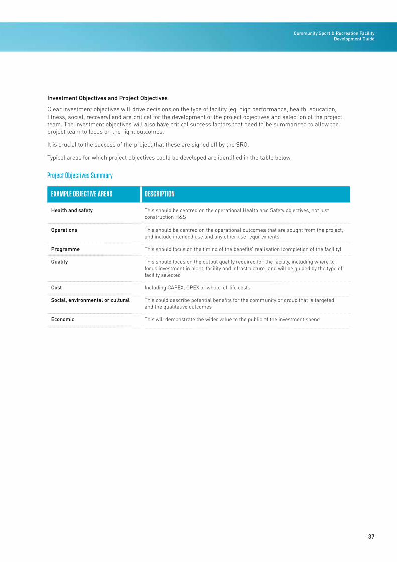
Investment Objectives and Project Objectives
Clear investment objectives will drive decisions on the type of facility (eg, high performance, health, education, fitness, social, recovery) and are critical for the development of the project objectives and selection of the project team. The investment objectives will also have critical success factors that need to be summarised to allow the project team to focus on the right outcomes.
It is crucial to the success of the project that these are signed off by the SRO.
Typical areas for which project objectives could be developed are identified in the table below.
Project Objectives Summary
EXAMPLE OBJECTIVE AREAS DESCRIPTION
Health and safety This should be centred on the operational Health and Safety objectives, not just construction H&S
Operations This should be centred on the operational outcomes that are sought from the project, and include intended use and any other use requirements
Programme This should focus on the timing of the benefits’ realisation (completion of the facility)
Quality This should focus on the output quality required for the facility, including where to focus investment in plant, facility and infrastructure, and will be guided by the type of facility selected
Cost Including CAPEX, OPEX or whole-of-life costs
Social, environmental or cultural This could describe potential benefits for the community or group that is targeted and the qualitative outcomes
Economic This will demonstrate the wider value to the public of the investment spend
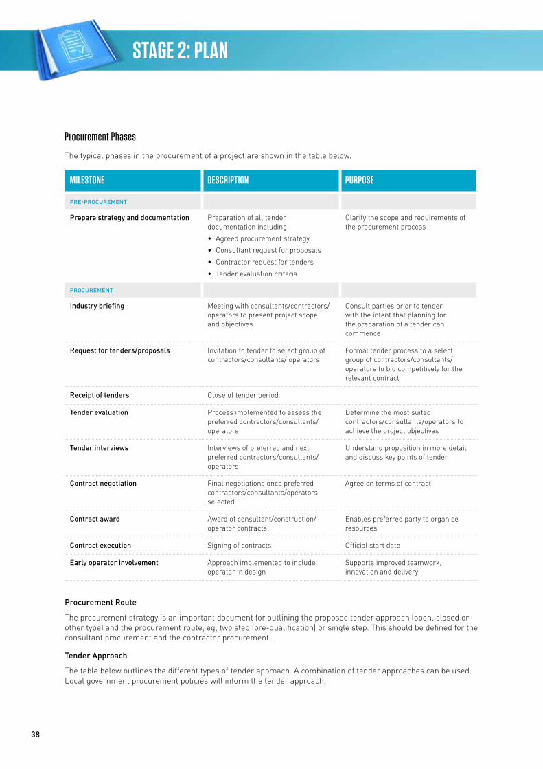
38
STAGE 2: PLAN
Procurement Phases
The typical phases in the procurement of a project are shown in the table below.
MILESTONE DESCRIPTION PURPOSE
PRE-PROCUREMENT
Prepare strategy and documentation Preparation of all tender documentation including:
• Agreed procurement strategy
• Consultant request for proposals
• Contractor request for tenders
• Tender evaluation criteria
Clarify the scope and requirements of the procurement process
PROCUREMENT
Industry briefing Meeting with consultants/contractors/operators to present project scope and objectives
Consult parties prior to tender with the intent that planning for the preparation of a tender can commence
Request for tenders/proposals Invitation to tender to select group of contractors/consultants/ operators
Formal tender process to a select group of contractors/consultants/ operators to bid competitively for the relevant contract
Receipt of tenders Close of tender period
Tender evaluation Process implemented to assess the preferred contractors/consultants/operators
Determine the most suited contractors/consultants/operators to achieve the project objectives
Tender interviews Interviews of preferred and next preferred contractors/consultants/ operators
Understand proposition in more detail and discuss key points of tender
Contract negotiation Final negotiations once preferred contractors/consultants/operators selected
Agree on terms of contract
Contract award Award of consultant/construction/ operator contracts
Enables preferred party to organise resources
Contract execution Signing of contracts Official start date
Early operator involvement Approach implemented to include operator in design
Supports improved teamwork, innovation and delivery
Procurement Route
The procurement strategy is an important document for outlining the proposed tender approach (open, closed or other type) and the procurement route, eg, two step (pre-qualification) or single step. This should be defined for the consultant procurement and the contractor procurement.
Tender Approach
The table below outlines the different types of tender approach. A combination of tender approaches can be used. Local government procurement policies will inform the tender approach.
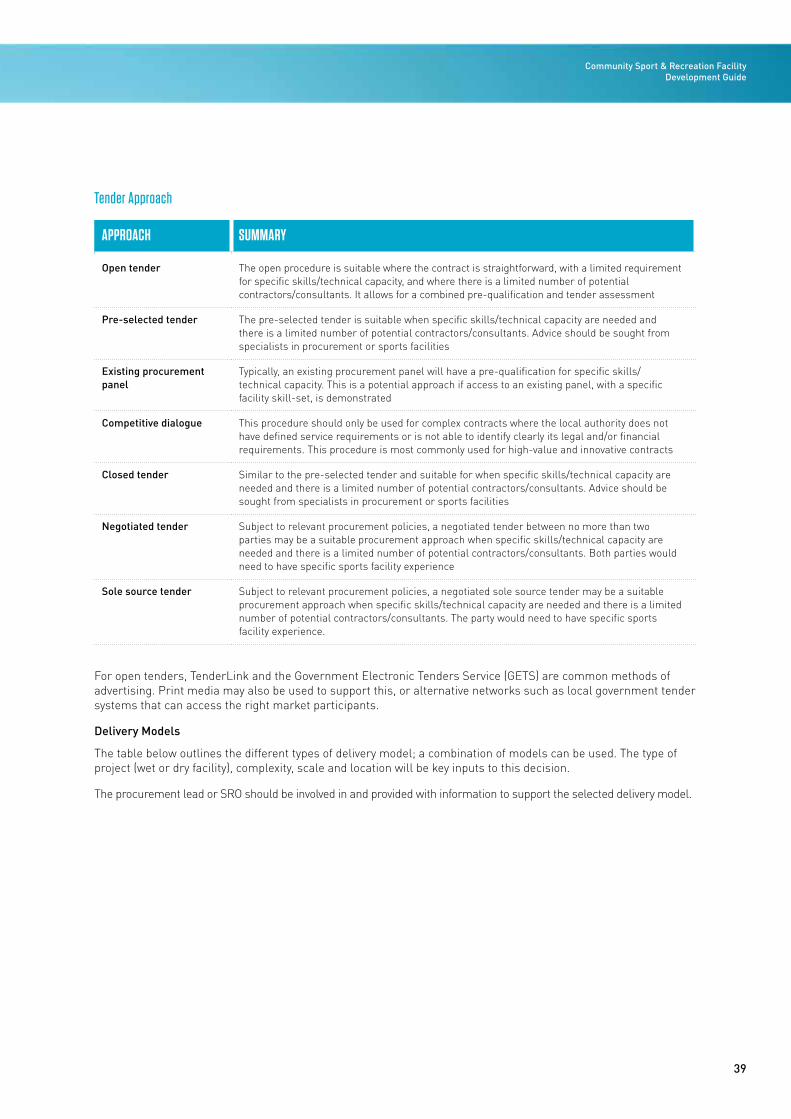
39
Community Sport & Recreation Facility Development Guide
Tender Approach
APPROACH SUMMARY
Open tender The open procedure is suitable where the contract is straightforward, with a limited requirement for specific skills/technical capacity, and where there is a limited number of potential contractors/consultants. It allows for a combined pre-qualification and tender assessment
Pre-selected tender The pre-selected tender is suitable when specific skills/technical capacity are needed and there is a limited number of potential contractors/consultants. Advice should be sought from specialists in procurement or sports facilities
Existing procurement panel
Typically, an existing procurement panel will have a pre-qualification for specific skills/technical capacity. This is a potential approach if access to an existing panel, with a specific facility skill-set, is demonstrated
Competitive dialogue This procedure should only be used for complex contracts where the local authority does not have defined service requirements or is not able to identify clearly its legal and/or financial requirements. This procedure is most commonly used for high-value and innovative contracts
Closed tender Similar to the pre-selected tender and suitable for when specific skills/technical capacity are needed and there is a limited number of potential contractors/consultants. Advice should be sought from specialists in procurement or sports facilities
Negotiated tender Subject to relevant procurement policies, a negotiated tender between no more than two parties may be a suitable procurement approach when specific skills/technical capacity are needed and there is a limited number of potential contractors/consultants. Both parties would need to have specific sports facility experience
Sole source tender Subject to relevant procurement policies, a negotiated sole source tender may be a suitable procurement approach when specific skills/technical capacity are needed and there is a limited number of potential contractors/consultants. The party would need to have specific sports facility experience.
For open tenders, TenderLink and the Government Electronic Tenders Service (GETS) are common methods of advertising. Print media may also be used to support this, or alternative networks such as local government tender systems that can access the right market participants.
Delivery Models
The table below outlines the different types of delivery model; a combination of models can be used. The type of project (wet or dry facility), complexity, scale and location will be key inputs to this decision.
The procurement lead or SRO should be involved in and provided with information to support the selected delivery model.
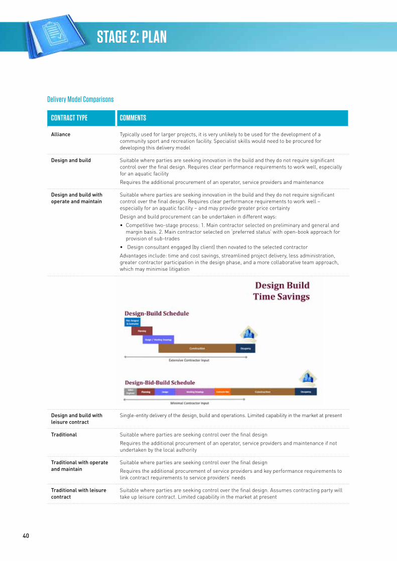
40
STAGE 2: PLAN
Delivery Model Comparisons
CONTRACT TYPE COMMENTS
Alliance Typically used for larger projects, it is very unlikely to be used for the development of a community sport and recreation facility. Specialist skills would need to be procured for developing this delivery model
Design and build Suitable where parties are seeking innovation in the build and they do not require significant control over the final design. Requires clear performance requirements to work well, especially for an aquatic facility
Requires the additional procurement of an operator, service providers and maintenance
Design and build with operate and maintain
Suitable where parties are seeking innovation in the build and they do not require significant control over the final design. Requires clear performance requirements to work well – especially for an aquatic facility – and may provide greater price certainty
Design and build procurement can be undertaken in different ways:
• Competitive two-stage process: 1. Main contractor selected on preliminary and general and margin basis. 2. Main contractor selected on ‘preferred status’ with open-book approach for provision of sub-trades
• Design consultant engaged (by client) then novated to the selected contractor
Advantages include: time and cost savings, streamlined project delivery, less administration, greater contractor participation in the design phase, and a more collaborative team approach, which may minimise litigation
Design and build with leisure contract
Single-entity delivery of the design, build and operations. Limited capability in the market at present
Traditional Suitable where parties are seeking control over the final design
Requires the additional procurement of an operator, service providers and maintenance if not undertaken by the local authority
Traditional with operate and maintain
Suitable where parties are seeking control over the final design
Requires the additional procurement of service providers and key performance requirements to link contract requirements to service providers’ needs
Traditional with leisure contract
Suitable where parties are seeking control over the final design. Assumes contracting party will take up leisure contract. Limited capability in the market at present
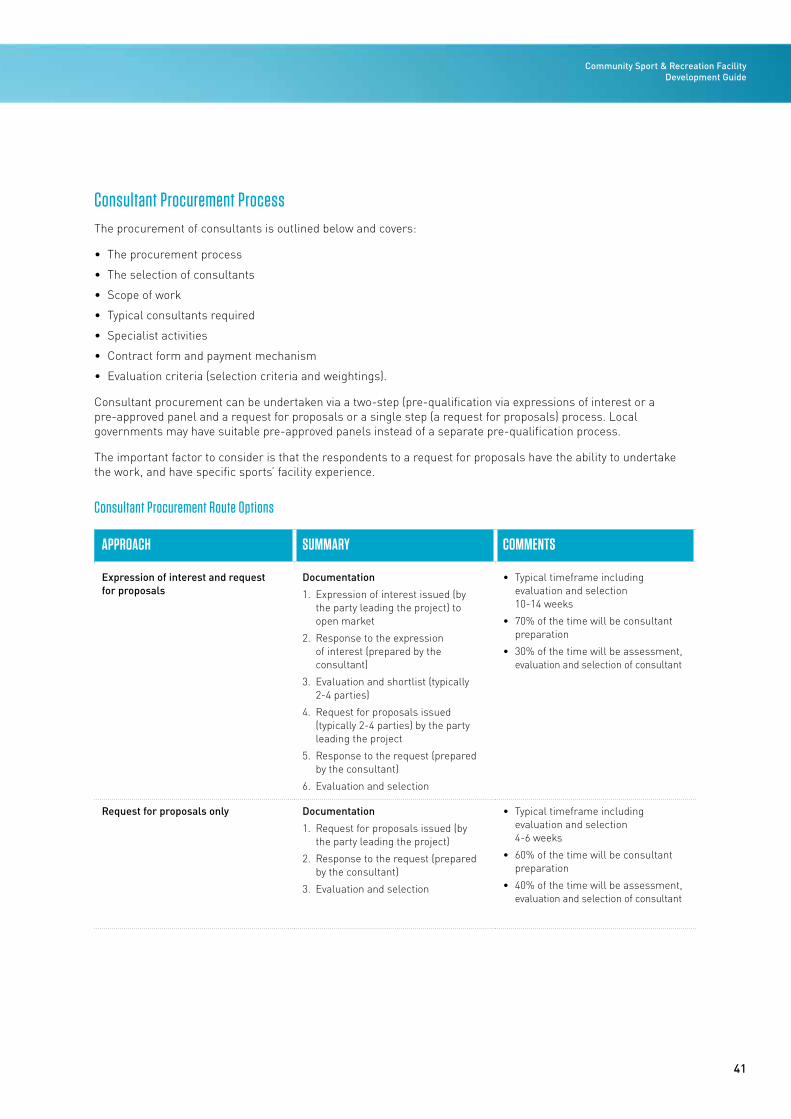
41
Community Sport & Recreation Facility Development Guide
Consultant Procurement ProcessThe procurement of consultants is outlined below and covers:
• The procurement process
• The selection of consultants
• Scope of work
• Typical consultants required
• Specialist activities
• Contract form and payment mechanism
• Evaluation criteria (selection criteria and weightings).
Consultant procurement can be undertaken via a two-step (pre-qualification via expressions of interest or a pre-approved panel and a request for proposals or a single step (a request for proposals) process. Local governments may have suitable pre-approved panels instead of a separate pre-qualification process.
The important factor to consider is that the respondents to a request for proposals have the ability to undertake the work, and have specific sports’ facility experience.
Consultant Procurement Route Options
APPROACH SUMMARY COMMENTS
Expression of interest and request for proposals
Documentation
1. Expression of interest issued (by the party leading the project) to open market
2. Response to the expression of interest (prepared by the consultant)
3. Evaluation and shortlist (typically 2-4 parties)
4. Request for proposals issued (typically 2-4 parties) by the party leading the project
5. Response to the request (prepared by the consultant)
6. Evaluation and selection
• Typical timeframe including evaluation and selection 10-14 weeks
• 70% of the time will be consultant preparation
• 30% of the time will be assessment, evaluation and selection of consultant
Request for proposals only Documentation
1. Request for proposals issued (by the party leading the project)
2. Response to the request (prepared by the consultant)
3. Evaluation and selection
• Typical timeframe including evaluation and selection 4-6 weeks
• 60% of the time will be consultant preparation
• 40% of the time will be assessment, evaluation and selection of consultant
42
STAGE 2: PLAN
Selection of Consultants
Once a procurement process and preferred contracting type have been selected, the project team can be procured to provide advice or undertake the design or project management of the facility. The important steps in the selection of consultants are:
• Agree the procurement process
• Develop the scope of the consultants’ work
• Select the contract form and payment mechanism.
Approach to Selecting Consultants
Typically, consultants are selected through either a pre-selected tender or an existing procurement panel.
Scope of Consultants’ Work
The scope of consultants’ work should align with the following policies and guidelines of the:
• New Zealand Institute of Architects
• New Zealand Construction Industry Council (NZCIC).
www.nzia.co.nz www.ncic.co.nz
The above documents provide a clear scope of works, outline the timing of when the scope is required, and define the outputs required for the drawings and technical specifications/reports at each design stage.
Specialist scope may need to be developed to address the particular requirements of each project.
Typical Consultants Required
The following table provides an overview of a typical project team and the consultants that may be required to deliver a community sport and recreational facility.
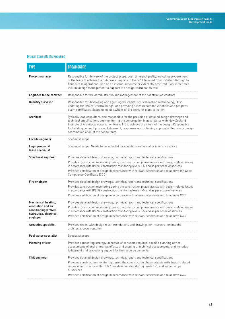
43
Community Sport & Recreation Facility Development Guide
Typical Consultants Required
TYPE BROAD SCOPE
Project manager Responsible for delivery of the project scope, cost, time and quality, including procurement of the team to achieve the outcomes. Reports to the SRO. Involved from initiation through to handover to operations. Can be an internal resource or externally procured. Can sometimes include design management to support the design coordination role
Engineer to the contract Responsible for the administration and management of the construction contract
Quantity surveyor Responsible for developing and agreeing the capital cost estimation methodology. Also updating the project control budget and providing assessments for variations and progress claim certificates. Scope to include whole-of-life costs for plant selection
Architect Typically lead consultant, and responsible for the provision of detailed design drawings and technical specifications and monitoring the construction in accordance with New Zealand Institute of Architects observation levels 1-5 to achieve the intent of the design. Responsible for building consent process, lodgement, responses and obtaining approvals. Key role is design coordination of all of the consultants
Façade engineer Specialist scope
Legal property/ lease specialist
Specialist scope. Needs to be included for specific commercial or insurance advice
Structural engineer Provides detailed design drawings, technical report and technical specifications
Provides construction monitoring during the construction phase, assists with design-related issues in accordance with IPENZ construction monitoring levels 1-5, and as per scope of services
Provides certification of design in accordance with relevant standards and to achieve the Code Compliance Certificate (CCC)
Fire engineer Provides detailed design drawings, technical report and technical specifications
Provides construction monitoring during the construction phase, assists with design-related issues in accordance with IPENZ construction monitoring levels 1-5, and as per scope of services
Provides certification of design in accordance with relevant standards and to achieve CCC
Mechanical heating, ventilation and air conditioning (HVAC), hydraulics, electrical engineer
Provides detailed design drawings, technical report and technical specifications
Provides construction monitoring during the construction phase, assists with design-related issues in accordance with IPENZ construction monitoring levels 1-5, and as per scope of services
Provides certification of design in accordance with relevant standards and to achieve CCC
Acoustics specialist Provides report with design recommendations and drawings for incorporation into the architect’s documentation
Pool water specialist Specialist scope
Planning officer Provides consenting strategy, schedule of consents required, specific planning advice, assessments of environmental effects and scoping of technical assessments, and includes lodgement and processing support for the resource consents
Civil engineer Provides detailed design drawings, technical report and technical specifications
Provides construction monitoring during the construction phase, assists with design-related issues in accordance with IPENZ construction monitoring levels 1-5, and as per scope of services
Provides certification of design in accordance with relevant standards and to achieve CCC
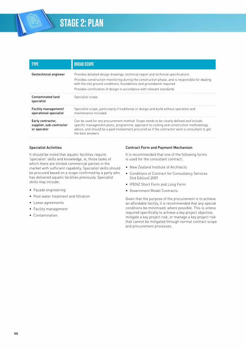
44
STAGE 2: PLAN
TYPE BROAD SCOPE
Geotechnical engineer Provides detailed design drawings, technical report and technical specifications
Provides construction monitoring during the construction phase, and is responsible for dealing with the site ground conditions, foundations and groundwork required
Provides certification of design in accordance with relevant standards
Contaminated land specialist
Specialist scope
Facility management/operational specialist
Specialist scope, particularly if traditional or design and build without operation and maintenance included.
Early contractor, supplier, sub-contractor or operator
Can be used for any procurement method. Scope needs to be clearly defined and include specific management plans, programme, approach to costing and construction methodology advice, and should be a paid involvement procured as if the contractor were a consultant to get the best answers
Specialist Activities
It should be noted that aquatic facilities require ‘specialist’ skills and knowledge, ie, those tasks of which there are limited commercial parties in the market with sufficient capability. Specialist skills should be procured based on a scope confirmed by a party who has delivered aquatic facilities previously. Specialist skills may include:
• Façade engineering
• Pool water treatment and filtration
• Lease agreements
• Facility management
• Contamination.
Contract Form and Payment Mechanism
It is recommended that one of the following forms is used for the consultant contract:
• New Zealand Institute of Architects
• Conditions of Contract for Consultancy Services (3rd Edition) 2009
• IPENZ Short Form and Long Form
• Government Model Contracts.
Given that the purpose of the procurement is to achieve an affordable facility, it is recommended that any special conditions be minimised, where possible. This is unless required specifically to achieve a key project objective, mitigate a key project risk, or manage a key project risk that cannot be mitigated through normal contract scope and procurement processes.
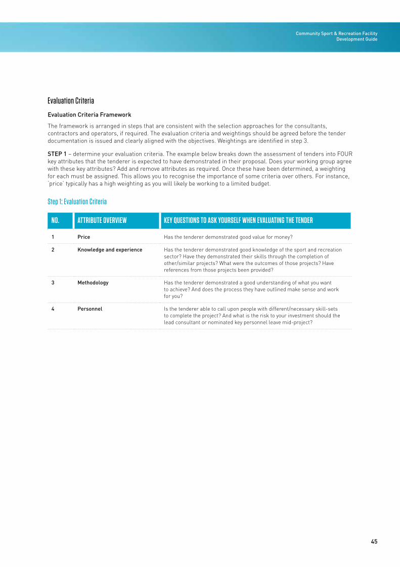
45
Community Sport & Recreation Facility Development Guide
Evaluation Criteria
Evaluation Criteria Framework
The framework is arranged in steps that are consistent with the selection approaches for the consultants, contractors and operators, if required. The evaluation criteria and weightings should be agreed before the tender documentation is issued and clearly aligned with the objectives. Weightings are identified in step 3.
STEP 1 – determine your evaluation criteria. The example below breaks down the assessment of tenders into FOUR key attributes that the tenderer is expected to have demonstrated in their proposal. Does your working group agree with these key attributes? Add and remove attributes as required. Once these have been determined, a weighting for each must be assigned. This allows you to recognise the importance of some criteria over others. For instance, ‘price’ typically has a high weighting as you will likely be working to a limited budget.
Step 1: Evaluation Criteria
NO. ATTRIBUTE OVERVIEW KEY QUESTIONS TO ASK YOURSELF WHEN EVALUATING THE TENDER
1 Price Has the tenderer demonstrated good value for money?
2 Knowledge and experience Has the tenderer demonstrated good knowledge of the sport and recreation sector? Have they demonstrated their skills through the completion of other/similar projects? What were the outcomes of those projects? Have references from those projects been provided?
3 Methodology Has the tenderer demonstrated a good understanding of what you want to achieve? And does the process they have outlined make sense and work for you?
4 Personnel Is the tenderer able to call upon people with different/necessary skill-sets to complete the project? And what is the risk to your investment should the lead consultant or nominated key personnel leave mid-project?
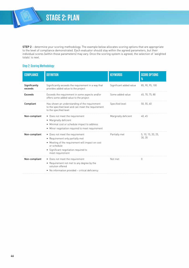
46
STAGE 2: PLAN
STEP 2 – determine your scoring methodology. The example below allocates scoring options that are appropriate to the level of compliance demonstrated. Each evaluator should stay within the agreed parameters, but their individual scores (within those parameters) may vary. Once the scoring system is agreed, the selection of ‘weighted totals’ is next.
Step 2: Scoring Methodology
COMPLIANCE DEFINITION KEYWORDS SCORE OPTIONS%
Significantly exceeds
Significantly exceeds the requirement in a way that provides added value to the project
Significant added value 85, 90, 95, 100
Exceeds Exceeds the requirement in some aspects and/or offers some added value to the project
Some added value 65, 70, 75, 80
Compliant Has shown an understanding of the requirement to the specified level and can meet the requirement to the specified level
Specified level 50, 55, 60
Non-compliant • Does not meet the requirement
• Marginally deficient
• Minimal cost or schedule impact to address
• Minor negotiation required to meet requirement
Marginally deficient 40, 45
Non-compliant • Does not meet the requirement
• Requirement only partially met
• Meeting of the requirement will impact on cost or schedule
• Significant negotiation required to meet requirement
Partially met 5, 10, 15, 20, 25, 30, 35
Non-compliant • Does not meet the requirement
• Requirement not met to any degree by the solution offered
• No information provided – critical deficiency
Not met 0
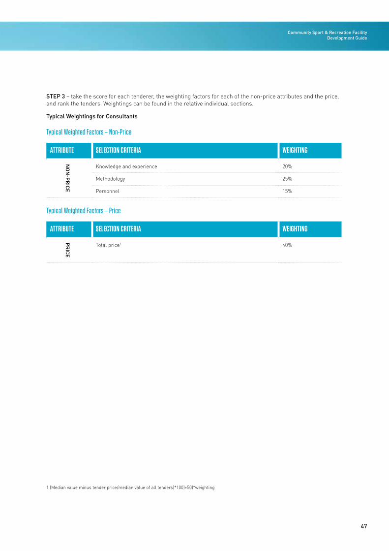
47
Community Sport & Recreation Facility Development Guide
STEP 3 – take the score for each tenderer, the weighting factors for each of the non-price attributes and the price, and rank the tenders. Weightings can be found in the relative individual sections.
Typical Weightings for Consultants
Typical Weighted Factors – Non-Price
ATTRIBUTE SELECTION CRITERIA WEIGHTING
NO
N-P
RIC
E
Knowledge and experience 20%
Methodology 25%
Personnel 15%
Typical Weighted Factors – Price
ATTRIBUTE SELECTION CRITERIA WEIGHTING
PR
ICE
Total price1 40%
1 (Median value minus tender price/median value of all tenders)*100)+50)*weighting
Community Sport & Recreation Facility Development Guide / 2016
STAGE 3
49
STAGE 3: DESIGN Community Sport & Recreation Facility Development Guide
Introduction
General
The design, construction and operation of community sport and recreation facilities, especially aquatic facilities, are extremely challenging in harsh environments. It is recommended that an experienced professional consultant team be engaged and that the works be designed and constructed in accordance with all relevant codes and standards. General design procedures and criteria for the design of a community sport and recreation facility are presented in the following sections of this design brief. These cover procedures and materials commonly used in the design and construction of facilities of this type in New Zealand. They are recognised Acceptable Solutions and Verification Methods to establish compliance with the performance requirements of the Building Code.
Various options have been considered for the design and construction of these facilities, and it is noted that other options are also possible. No option has been ruled out as being unsuitable. Other options should be considered during the design phase of a project by your appointed professional consultant team, provided compliance with the Building Code can be demonstrated. This will be by way of an Acceptable Solution using recognised procedures and materials that are not necessarily specifically covered in this brief, or with an Alternative Solution as defined in the Building Code.
The design of a community sport and recreation facility will involve a consideration of the size, location and nature of the site and its surrounds, the facilities to be developed, the objectives of the facility, the primary user groups and the budget.
Implementing a facility design that suits the activities and the users is also a component of success. Responsive design can create a place where people come to play, meet and connect with the local community, that is inviting and stimulating, visually sensitive and expressive, and has a feel-good atmosphere for people of all ages and cultures.
Building Act 2004
The Building Act covers the construction, alteration, demolition and maintenance of new and existing buildings throughout New Zealand. It sets standards and procedures for people involved in building work (including licensing of building practitioners) to ensure buildings are safe, healthy and built right first time. It covers how work can be done, who can do it, and when it needs to be consented and inspected. The Building Act as it relates to buildings is implemented by local district and city councils.
Under the Building Act, the Building Code defines the minimum standards that buildings must meet (to the extent required by the Act). In contrast to the plans prepared under the Resource Management Act 1991 (RMA), the Building Code provides a common set of minimum rules for the whole of New Zealand.
Building Code/Codes of Practice/Standards
Building Code
All building work in New Zealand must comply with the Building Code, which is the first schedule to the Building Regulations 1992. It is a performance-based code, which means it states how a building must perform in its intended use rather than describing how the building must be designed and constructed.
The Building Code does not prescribe how work should be done but states, in general terms, how the completed building must perform in its intended use. The Building Code contains functional requirements and performance criteria that cover matters such as protection from fire, structural strength, moisture control and durability.
Building plans and specifications are assessed by building consent authorities (usually the local authority) to ensure that the completed building work complies with the Building Code. When the building consent authority (BCA) is satisfied, it will issue a building consent for the work to proceed.
The Building Code consists of two preliminary clauses and 37 technical clauses. Each technical clause, except for the ‘C’ clauses for protection from fire, contains:
1. Objectives – the social objectives that the completed building work must achieve.
2. Functional requirements – what the completed building work must do to satisfy the social objectives.
50
STAGE 3: DESIGN
3. Performance criteria – qualitative or quantitative criteria with which buildings must comply in their intended use.
Clause C1 contains the Objectives for the Protection from Fire Clauses C2 to C6. Clauses C2 to C6 contain only Functional Requirements and Performances.
Acceptable Solutions and Verification Methods, relating to particular Building Code clauses, are produced by the Ministry of Business, Innovation and Employment (MBIE) to provide a means of establishing compliance with the Building Code. They provide information on materials, construction details and calculation methods that, if followed, must be accepted by a BCA as complying with the related Building Code provisions.
Acceptable Solutions and Verification Methods are only one way of complying with the Building Code. Alternative Solutions can also be used. An Alternative Solution is a building design, of all or part of a building, which differs from the design or method in an Acceptable Solution or Verification Method but still complies with the Building Code. It can include a material, component or construction method that differs completely or partially from those described in an Acceptable Solution or Verification Method. An Alternative Solution must be evaluated and accepted by the BCA when application is made for a building consent before it can be used.
Codes of Practice and References
Codes of practice and sources of reference for New Zealand building construction are issued by MBIE and are provided to assist BCAs, building owners, designers and persons who carry out building work. They do not have the ‘deemed to comply’ status accorded to Acceptable Solutions and Verification Methods by the Building Act, and are not intended as means of establishing compliance with the Act or the Building Code.
Standards
Standards are agreed specifications for products, processes, services and performance. If, for example, an electrical product is marked as meeting a standard, it means it meets the minimum safety requirements.
Every day, standards and standardisation make a difference in the lives of New Zealanders. Standards’ solutions help to keep our homes, public buildings, playgrounds, electrical appliances and health services safe. They can also be used to protect people and our environment and to increase productivity and drive innovation. Standards are generally voluntary, but can
be mandatory when cited in Acts, regulations and other legislative instruments.
Standards may also be referenced in regulations as one means of compliance or as an Acceptable Solution under those regulations, without being mandatory. Standards are a successful way to bridge government regulation and industry self-regulation.
Building Consent
The Building Act specifies that building consent applications must be processed within 20 working days. The process goes on hold if the council has to ask for any more information and it doesn’t start again until it receives it. If you get all your documents together before you lodge your application, the process should go quickly and smoothly.
An incomplete application will take council staff longer to process and you could be charged accordingly. The fees may be based on the value of the proposed building work and/or the time it takes to complete the assessment.
A council can grant or decline a building consent application. Generally, however, a consent must be granted by a council if it is satisfied that the provisions of the Building Code will be met.
If your application is approved, you should carefully read and be sure that you understand the conditions of your building consent. The consent directs you to build what is shown in your plans, and during inspections building officials will judge the work against those plans.
If your application is declined, the council will tell you the reasons why. You may need to seek help from your expert advisers or council staff.
If you believe the council is wrong you can ask MBIE for a determination, which is a legally binding decision on disputes or questions about the rules that apply to buildings. A determination can be appealed to the District Court.
Once a building consent has been obtained construction on the site can commence. There are, however, some other important points to note:
• Your building consent will lapse if you don’t start your building work within 12 months unless you have made arrangements with the council for a longer period to apply. If the building consent lapses and you still want to do the work, you will have to apply for a new building consent
51
Community Sport & Recreation Facility Development Guide
• The Building Act anticipates that building work will be completed and a CCC applied for within two years of the building consent being granted. An extension to this two-year period can be agreed with the council
• The council can issue a notice to fix if you don’t comply with the Building Act, eg, if you don’t follow your building consent or don’t comply with the inspection process. A notice to fix requires you to put right any breaches of the Building Act. You could be fined if you, or your builder, fail to comply with a notice to fix.
Code Compliance Certificate
When the project is complete, you must arrange for a final inspection and then apply to the council for a CCC. The council has 20 working days from the date of your application to decide whether to issue one. If the council requests further information, the process goes on hold until the information is received. A CCC is issued when the council is satisfied the completed building work complies with the building consent. It provides an assurance to both you and future owners that the building work was done to the appropriate standards.
If you don’t submit an application for a CCC within two years of being granted your building consent, and you haven’t agreed an extension with the council, it will follow up with you and may decide then whether to grant a CCC.
Because any resource consent you have is likely to relate not just to the activity of construction but to the ongoing use of the land or buildings, there are likely to be conditions in your consent that require ongoing compliance on your part, as well as potential monitoring obligations. Typically, these conditions relate to things such as a requirement to seal the driveway or paint a building in certain colours. In the event that you sell your property, the resource consent (in the case of a land use or subdivision consent) along with the obligation to comply with any conditions transfers automatically to the new owner.
NZCIC Guidelines
The design of a building is a key stage in a development and the guidelines produced by NZCIC set a benchmark to which all parties involved in a project can refer. The careful identification of the client brief and needs, and advice from the professional design consultants to the client on the most advantageous outcomes, are important ancillary functions that should be linked to these guidelines.
The quality of design documentation is critical to the success of any building project. Buildings today are very complex in all facets, including form, structure, services and cladding, particularly those associated with aquatic facilities. Building elements are much more tightly designed than in the past. This has resulted in a situation where ‘standard’ building details often do not apply to a large portion of a project.
Design documents provide the critical ties between all parties in a building project. However, there has been a lack of definition of design documentation that all parties can rely on.
The purpose of the NZCIC Design Guidance Guidelines is to:
• Define clearly the design responsibilities from the outset and communicate these to all parties involved in the project
• Define the scope of design services with the client and communicate this to all parties to the design process
• Provide a ‘level playing field’ in achieving appropriate remuneration for the standard of design service required
• Provide a quality assurance reference for users.
The Guidelines differentiate the design process and deliverables can be used to define the responsibilities of the various parties throughout the design process (tick-boxes are provided for easy definitions of scope). The level of service provided by a ‘designer’ could be curtailed at any of the stages. The parties completing the design process will need to carry out the remaining steps in a coordinated manner to achieve an effective design.
The document has separate guidelines for the primary design disciplines of architecture, structure, HVAC services, fire protection, hydraulic services, fire engineering, electrical services and electrical ancillary services. The input from other specialist ‘designers’, such as geotechnical, acoustic, pool water services, vertical transportation and wind consultants, will need to be coordinated effectively with the design team. Separate guidelines have not been created for these specialist consultants.
www.nzcic.co.nz/resources/guideance-documents

52
STAGE 3: DESIGN
Design Phases/Stages
All building projects go through a similar design process irrespective of the building type, procurement methodology or programme. This design process is made up of a number of ‘phases’ or ‘stages’. The key design phases of a building-type project include:
Concept Design
Generally involves the application of a design ‘idea’ to the practical provision of a facility. It represents a phase where sufficient design concepts are developed for the client to be able to establish the feasibility of the project or the development potential of a site, or to select a particular conceptual approach that they wish to pursue. The concept design phase may be used to define or verify the brief and often involves the testing of different approaches/options. During this phase, ideas and concepts are more fully developed through open interaction and discussion between the project and design teams in regard to the key components of the project.
At the end of this phase, the basic building blocks of the project are defined in general terms and coordinated between the design disciplines.
Concept and preliminary design phases are often combined in less complex projects.
Preliminary Design
Generally involves the further refinement of the preferred concept to facilitate testing it against inputs from the team, including cost estimates and regulatory approval. This may provide sufficient information for the communication of the design to a third party for marketing or consultation purposes.
During this phase the project concepts are developed into firm schemes, where the relationships and sizes of spaces and facilities are defined and coordinated between the design disciplines. However, the resolution of individual details that do not impact on the key elements is generally left for the next design phase. At the end of this phase, the project should be clearly defined.
Developed Design
Is the phase where the scope of each component in the design is clearly defined and coordinated. This may involve the production of detailed information, including sketch details of all significant componentry and their interrelationships. The developed design phase is where the individual technical experts prepare the necessary documentation to define the scope of all building elements. Major input is required by all designers.
The completion of the developed design is a critical point in a project. The scope of the project is fully defined. As a result, cost estimates can be prepared on an elemental basis. Developed design generally provides sufficient information for the client/user to clearly understand the aesthetics and functionality of the building, internal spaces and facilities.
On some projects the developed design documentation is issued for building consent and/or guaranteed maximum price tender. Coordination between the design disciplines is therefore critically important at the end of this stage.
Detailed Design
Generally provides a level of documentation that clearly defines the design, specifications and extent of all building elements. The design should be comprehensively coordinated with other disciplines. However, the documents produced in this phase may not directly be able to be ‘built’ from. Changes to anything but detail at this stage are very disruptive and expensive and often result in further problems as, by now, the project has become very complex and it is hard to identify all the ramifications of changes. Detailed design is the phase most commonly used to obtain a tender for the construction of the works.
Construction Design
Is where the requirements defined in detailed design documents are integrated with changes that may occur during the tender and contract process, and with construction requirements such as site conditions, proprietary and performance design elements, erection requirements and fabricated shop drawings to create drawings that can be directly ‘built’ from. (Note: shop drawings are produced during this stage.) This stage is normally completed by the contractor and the specialist sub-trades/contractors. These documents are issued to the design team for review.
Value Management
Value management (VM) reviews at the appropriate stage(s) of the design process may assist in achieving a successful project. However, reviews undertaken too late can be ineffective and adversely impact on the programme and costs. The sketch below graphically illustrates the opportunity of early reviews. Generally, VM reviews should be carried out at the end of the concept and/or preliminary design stage, when the design has been coordinated between the design disciplines and there is a consistent basis for a cost estimate. The necessary revisions that are identified as part of the VM review can then be input to the start of the next design phase.
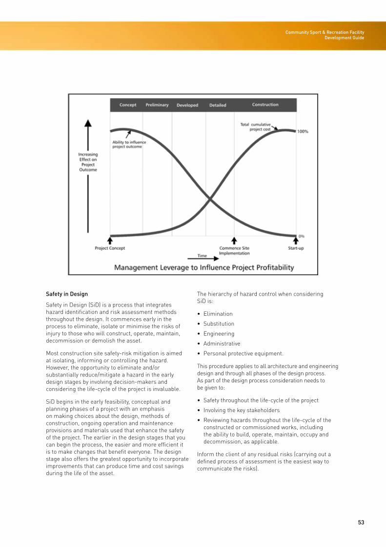
53
Community Sport & Recreation Facility Development Guide
Safety in Design
Safety in Design (SiD) is a process that integrates hazard identification and risk assessment methods throughout the design. It commences early in the process to eliminate, isolate or minimise the risks of injury to those who will construct, operate, maintain, decommission or demolish the asset.
Most construction site safety-risk mitigation is aimed at isolating, informing or controlling the hazard. However, the opportunity to eliminate and/or substantially reduce/mitigate a hazard in the early design stages by involving decision-makers and considering the life-cycle of the project is invaluable.
SiD begins in the early feasibility, conceptual and planning phases of a project with an emphasis on making choices about the design, methods of construction, ongoing operation and maintenance provisions and materials used that enhance the safety of the project. The earlier in the design stages that you can begin the process, the easier and more efficient it is to make changes that benefit everyone. The design stage also offers the greatest opportunity to incorporate improvements that can produce time and cost savings during the life of the asset.
The hierarchy of hazard control when considering SiD is:
• Elimination
• Substitution
• Engineering
• Administrative
• Personal protective equipment.
This procedure applies to all architecture and engineering design and through all phases of the design process. As part of the design process consideration needs to be given to:
• Safety throughout the life-cycle of the project
• Involving the key stakeholders
• Reviewing hazards throughout the life-cycle of the constructed or commissioned works, including the ability to build, operate, maintain, occupy and decommission, as applicable.
Inform the client of any residual risks (carrying out a defined process of assessment is the easiest way to communicate the risks).
54
STAGE 3: DESIGN
ArchitecturalThis section is intended to give the reader an understanding of the key components that may be provided in a community sports and recreation centre facility. It is divided into the following six sections:
• Site
• General facility components
• Aquatic components
• Dry sports components.
Site
Careful consideration should be given to points of access to ensure a welcoming, customer-friendly and accessible approach to the building. A careful integration with the site will also ensure level accessibility and minimise changes required to the site topography.
The particular shape and dimensions of a site are likely to create a number of constraints that will affect the building and site layout; these include a consideration of:
• Service and public access
• In-ground services and infrastructure
• Environmental factors (contours, orientation and prevailing winds)
• Landscape and urban design issues
• Geotechnical conditions
• Future expansion
• Legal issues (easements)
• Regional and local planning regulations (RMA, district plans).
All constraints should be carefully considered in order to ‘tailor’ the design sensitively for the particular location. This should include discussions and consultation with local stakeholders and planning and environmental departments. The constraints should be considered early in the project development process and it is therefore important to engage appropriate design consultants for professional advice.
Site Design Process
• Procure the consultant team. Consultants typically required to inform and develop the site design include:
Surveyor To carry out site survey to enable consultant team to develop a design
Architect To develop site master plan and concept design (for small sites may also include landscape design services)
Landscape architect
To provide landscape design strategy, often required for resource consent
Planner To provide specialist resource consent advice
Civil engineer To inform in-ground services infrastructure and stormwater system or consent requirements
Transport engineer
To inform parking numbers, road layouts, intersection designs, NZ Transport Agency (NZTA) liaison
• Develop a long-term master plan for the site based on the facility design brief and be clear about the long-term vision
• Develop a concept design for the building and site based on the facility brief.
Access and Transport
Community facilities may be located adjacent to schools. Where this is proposed the design must consider the need to provide dedicated school entrances, and change, locker and marshalling spaces.
Public bus and school coach drop-off and parking spaces may be required and should be considered in the design of the road network and parking layout.
An appropriate provision of carparking is needed to suit the particular location and local planning requirements. The larger the facility the greater the requirements for carparking and coach and bus drop-off and pick-up points. Carparking design should consider best-practice sustainable drainage systems. The number of carparks should be informed by professional advice and they should typically not be sized based on worst-case-event mode overlays.
55
Community Sport & Recreation Facility Development Guide
Future Expansion/Staging/Integration
In-ground services, parking and building location and layout are all affected by the future expansion intentions of the facility. It is therefore critical to brief and develop a master plan for the selected site before the concept design is developed and building location is determined. The site master plan must consider the long-term vision for the site and facility. The master plan will inform the location of the building, carpark and associated infrastructure.
Refer to the reference facility example in Stage 4 Build, page 143 for an example of a master plan that considers potential staging and hubbing during the life of the facility.
External Amenity
The site should be considered as an opportunity to provide further leisure and sports amenity. The landscape, urban and building design must carefully consider the site factors to sensitively ‘tailor’ the design to the particular location and enhance the local environment.
The public entrance to the building should encourage participation by promoting visibility of the sports through the use of external glazing. The landscaping design should create spaces for informal and formal outdoor play. Sheltered seating and BBQ areas may be considered in addition to providing basic seating adjacent to the pick-up and drop-off points.
General Facility Components
Entrance Lobby and Foyer
The main entrance to the facility should be located to consider the local site conditions, prevailing wind and solar orientation. Wind lobbies should be provided where entrances face prevailing wind directions or in climates where heat loss and/or cold draughts would be undesirable.
The foyer should provide sufficient area for large groups to queue or assemble while entering or exiting the building. For a typical-scale community facility, this will be up to one full school class or approximately 30 people. The provision of a large open space with lots of natural light is desirable. Foyer areas should be provided with seating for those waiting to collect others and for facility programme and general enquiries.
The foyer and entrance lobby should be physically and acoustically separate from the main sports areas but have strong visual connectedness. Reception staff
should have clear views of the internal and external circulation routes. Visitors should be provided with views into the internal sports areas from the reception point.
Automatic access–control gates should provide controlled entry to the pool change process and fitness centre sports areas. Space for notice boards and signage should be provided to communicate facility programmes, activities and important notices.
Reception, Administration and Staff Facilities
The reception area should be immediately apparent to those entering the facility and directly adjacent to the lobby and foyer. Adequate space for two people to operate behind the reception desk is typically required. The location should if possible provide supplementary, not primary, supervision of activity in the pool and sports areas so should be visually connected.
Offices for the functions of programme administration, facility operations and management should be provided and connected to, and ideally visible from, the reception area. A staff room with a kitchenette and space for the storage of food and personal belongings is required and should be large enough to hold informal staff meetings around a small table. Unisex staff change facilities should be provided, ideally with direct access from the staff room. A dry room or large cupboards is required for the storage of stationery and other office supplies.
Meeting Room
A small, well appointed meeting room with capacity for up to 25 people is desirable. This room can provide hire space for use by regular facility users and groups wishing to conduct small meetings on-site. It is typically not allocated to any one group or organisation and would also be used for regular community group or facility staff meetings.
Café/Food and Beverage Area
A facility to provide food and beverages is a core component of a successful community facility. The café or vending area should be sized to reflect local market conditions.
For small community facilities, a small vending area and space to sell ice creams and coffee should be integrated with, or adjacent to, the reception space. Tables and chairs should be provided for seating and viewing of the sports or pool halls, ideally with access to outdoor seating areas.
56
STAGE 3: DESIGN
Larger community facilities may consider providing a dedicated café but this must be justifiable and is unlikely to be based solely on the size of the facility. Factors such as the type of location, high street or rural, the local competition and the user numbers all need to be assessed. The choice of tenant will inform the fit-out of the space and discussions with prospective tenants must therefore occur early in the design process to inform the brief. A typical café should provide a small kitchen space, a dishwashing and kitchen waste area and a servery and seating area and may total 100-200m2. The servery should service and be highly visible from the main foyer, leisure water space and outdoor seating area.
Retail
A facility to sell goods such as sports apparel is a core component of a successful community facility. Small community facilities should integrate a retail area within or locate one immediately adjacent to the main reception area. The provision of a change cubicle should be considered to improve swimsuit sales.
A larger community facility has the potential to justify a dedicated retail space. In this case the retail area should be clearly visible and ideally immediately adjacent to the main entrance and foyer.
Public Toilets
Public toilets should be provided in close proximity to the main entrance foyer for use by spectators, non-sports participants and café patrons. These should provide male and female facilities and an accessible facility with baby change facilities as a minimum and be calculated in accordance with the Building Code Part G1.
Cleaners’ Stores
Cleaners’ stores should be located in strategic locations and sized to reflect the scale of the facility. A large central cleaners’ store with bucket sink and storage should be provided with smaller ancillary cleaners’ cupboards located in each change area.
First Aid Room
In small community facilities a first aid room is not required. First aid equipment should be integrated with key locations. The accessible change room with bed can often double as an emergency first aid room if required. In larger community facilities it may be necessary to provide a dedicated first aid room with a bed and a wash-hand basin. This should be located to service all facilities within the sports centre and have direct access to the pool facility and the general circulation. External access to an emergency vehicle access bay should be provided via a nearby door.
Spectator Viewing
Separate spectator viewing and entry to the indoor courts and pool hall should be provided directly from the foyer. Locating the spectator viewing and entry process adjacent to a café and vending area is advantageous to maximise spectators’ secondary spend.
Accessibility
Providing disability access to all sports areas and swimming pools is an important consideration for sports facility design, which should include the inclusion of permanent ramp access to all pools. There could be cases where adding a spa pool to an existing facility makes it impossible to provide ramp access due to space constraints. In these situations, and other exceptional circumstances, of alternative forms of accessible access, such as hoists, may be considered. If using a hoist, consideration needs to be given to its location in terms of both the pool and space pool-side for wheelchairs to be parked. When providing ramp access to pools, the location and gradient of the ramp are important factors to ensure safe entry. A storage space for water wheelchairs also needs to be considered in the design stage to ensure there is an appropriate place for these to be located.
Refer to the Barrier Free New Zealand Trust and Sport NZ Accessibility Design Guide and Self-Assessment Checklist for a list of requirements for each space.
www.sportnz.org.nz/accessibilityguide
Sport wheelchairs are wider than normal wheelchairs and are not able to fit through 760mm clear door openings. All accessible routes should therefore provide 920mm minimum clear openings. Sliding doors are preferred to swing doors.
57
Community Sport & Recreation Facility Development Guide
Aquatic Components
FINA
“FINA or Fédération Internationale de Natation (International Swimming Federation) is the International Federation recognised by the International Olympic Committee for administering international competition in Aquatics. FINA currently oversees competition in five aquatics sports: swimming, diving, synchronised swimming, water polo and open water swimming.”
FINA publishes Facilities Rules that describe the requirements for swimming pools that will host events held under these rules. The FINA Facility Rules describe dimensional, temperature, lighting and automatic officiating equipment (touch panels) requirements.
In the context of a typical community facility the lap pool and associated pool hall are rarely fully FINA-compliant. The costs associated with increasing lighting levels to the required minimum 600 lux for competition, and 1,000 lux for broadcast, and providing the automatic timing equipment and scoring systems are not affordable for a typical community facility. The recommended approach is therefore to design the pool length to comply with FINA rules (FR2.2 and FR2.3) but stop short of meeting all the ancillary requirements.
Those developing sport and recreation facilities that are intended to be used for competition where scoring and timing equipment is required will need to consider and include additional capital for its inclusion as part of the facility fit-outs.
Indicative costs for an eight-lane, 25m pool and single-court multi-sports hall:
System for 8-Lane Pool – Finish only – $105,087
The system elements make up the minimum requirements for an operational competition set of equipment. Provides mobile timing at one end of the pool and results on an eight-line scoreboard.
System for 8-Lane Pool – Finish and 25m/50m – $175,984
The system elements make up the minimum requirement for an operational competition set of equipment. Provides mobile timing at two ends of the pool and results on an eight-line scoreboard.
Sports Hall – Entry-Level Multi-sport Scoreboard and Scoring System – $15,520
A single court with baseline timekeeping and scoring equipment with scoreboard and two shot clocks. The controller comes pre-loaded with various software adapted to the following: basketball, volleyball, handball, hockey, netball, tennis, badminton, table tennis and indoor football. Does not include scorebench/seating
Note: prices (2015) exclude GST, installation and changes due to exchange rates.
Pool Layout and Concourse Design
The layout of pools within a facility needs to be considered in the context of access, thoroughfares, use levels, water flows, depths, safety and future expansion potential.
The layout of the pools should consider the safety of patrons by grouping similar-depth water bodies together. Depth markers should be provided at key entry points, ie, ladders and steps. Access to the pool hall from the change rooms should deliver patrons at a shallow-depth water body to ensure the safety of children. Where this is not possible handrails should be provided in addition to clear pool depth signs to limit the risks associated with children and deep water. For example, a ramp to a main pool can provide a useful safety device to separate patrons from the deep main pool water.
Concourse widths should be in accordance with NZS 4441:2008 Swimming Pool Design Standard and the following points should also be noted:
• The ‘joining’ of pools together with a shared wall in order to save space may be considered, but the acoustic limitations of two adjacent pools should be recognised
• A 3m width shall typically be provided between pools and around the outside concourse area. The 3m width shall be measured from the edge of the pool roll-out channel to the wall or adjacent pool roll-out channel. This dimension can typically be reduced where concourse areas are used only for circulating purposes. For example, a reduction in concourse width adjacent to a pool ramp is often satisfactory
• Ideally, 4m should be provided at the starting end of the main pool for competition. Small community facilities with no competitive programmes may reduce this.
58
STAGE 3: DESIGN
Pool-side showers should be provided adjacent to the spa pool and immediately adjacent to the change rooms to encourage patrons to shower before using the pools.
The height of the pool hall space should be considered in the context of the facility design, future expansion intentions and investment objectives. For example, a facility with a first-floor fitness centre, or intention to add one in the future, should consider and incorporate sufficient height to enable the fitness centre to overlook the pool hall. A consideration of the exposed mechanical air distribution systems will also affect the required pool hall height. For example, large-diameter air ducts should not be located less than 3m above the concourse. Competition intentions and spectator sight lines will also have an impact on the required ceiling height and therefore pool hall volume. Generally the smaller the volume, the lower the capital and operating costs. However, this must be balanced with the community leisure and amenity aspirations.
Main Pool
A typical community main pool consists of a 25m long pool, designed to FINA tolerances (ie, 25–25.03m) with 2.5m wide-lanes. Pool length tolerances should not be exceeded when touch panels are installed. A typical main pool is recommended to provide eight-lanes, which equates to a pool size of 25–25.03m long x 20m wide. Typically, the FINA requirement for “two spaces of at least 0.2 metres outside of the first and last lanes” is not considered necessary unless the community’s primary investment objective is for a competition venue.
A fewer number of lanes may be considered in small communities where capital cost considerations are paramount and community use is low. Equally, in larger community facilities consideration should be given to providing a larger 10-lane main pool as this has additional programming benefits associated with being able to run 25m laps across the width of the pool, thereby allowing best use of the benching in the shallow and deep water for other programme uses. It is rarely feasible to extend an eight-lane pool, so the 10-lane option should be considered at the design stage and the benefits reviewed against the investment objectives. Upstand end walls and rest ledges should be provided in accordance with FINA regulations. Consideration should be given to using a glossy tile at water level to minimise the ongoing cleaning requirements of community pools.
Access should be provided to every pool in accordance with the Sport NZ Accessibility Design Guide and Self-Assessment Checklist by providing a ramp. The ramp should not occupy any of the swimming lanes and should be separated from the main body of water with a wall. Three water depth options for the main pool floor are considered in the accompanying section diagrams.
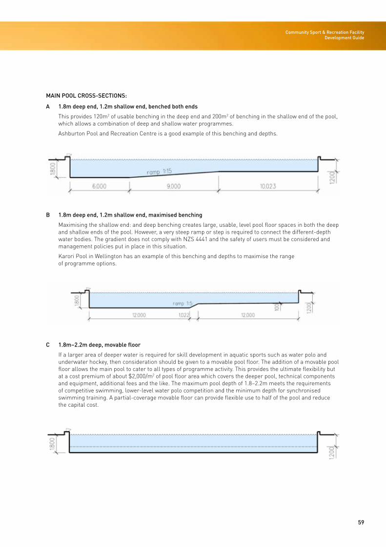
59
Community Sport & Recreation Facility Development Guide
MAIN POOL CROSS-SECTIONS:
A 1.8m deep end, 1.2m shallow end, benched both ends
This provides 120m2 of usable benching in the deep end and 200m2 of benching in the shallow end of the pool, which allows a combination of deep and shallow water programmes.
Ashburton Pool and Recreation Centre is a good example of this benching and depths.
B 1.8m deep end, 1.2m shallow end, maximised benching
Maximising the shallow end: and deep benching creates large, usable, level pool floor spaces in both the deep and shallow ends of the pool. However, a very steep ramp or step is required to connect the different-depth water bodies. The gradient does not comply with NZS 4441 and the safety of users must be considered and management policies put in place in this situation.
Karori Pool in Wellington has an example of this benching and depths to maximise the range of programme options.
C 1.8m–2.2m deep, movable floor
If a larger area of deeper water is required for skill development in aquatic sports such as water polo and underwater hockey, then consideration should be given to a movable pool floor. The addition of a movable pool floor allows the main pool to cater to all types of programme activity. This provides the ultimate flexibility but at a cost premium of about $2,000/m2 of pool floor area which covers the deeper pool, technical components and equipment, additional fees and the like. The maximum pool depth of 1.8–2.2m meets the requirements of competitive swimming, lower-level water polo competition and the minimum depth for synchronised swimming training. A partial-coverage movable floor can provide flexible use to half of the pool and reduce the capital cost.
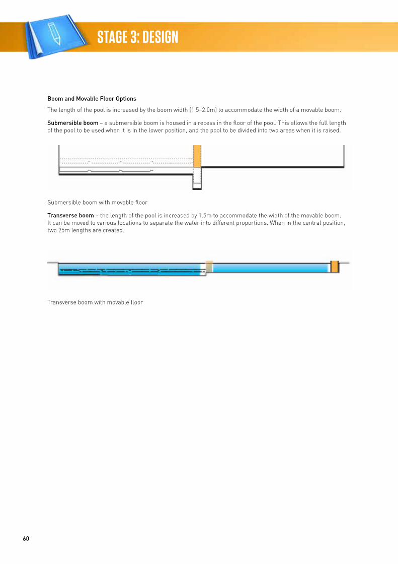
60
STAGE 3: DESIGN
Boom and Movable Floor Options
The length of the pool is increased by the boom width (1.5–2.0m) to accommodate the width of a movable boom.
Submersible boom – a submersible boom is housed in a recess in the floor of the pool. This allows the full length of the pool to be used when it is in the lower position, and the pool to be divided into two areas when it is raised.
Submersible boom with movable floor
Transverse boom – the length of the pool is increased by 1.5m to accommodate the width of the movable boom. It can be moved to various locations to separate the water into different proportions. When in the central position, two 25m lengths are created.
Transverse boom with movable floor
61
Community Sport & Recreation Facility Development Guide
Pool Control
A space to control the pool systems, audio visual equipment, water toys and leisure features is required. In small facilities this may be integrated with a control panel pool-side. The pool controls must be located where there is a direct line of sight to the water toys and pools. In larger community facilities, it is typical to provide a dedicated pool control room, which can also double as a pool competition timing room and is typically located overlooking the starting block end of the main pool.
Main Pool Spectator Seating
The area to provide for seating can add significantly to the cost of a project, and the requirement for this and the frequency and level of any competitive events should be considered. The cost per seat is approximately $2,500-$3,000 including building area (based on 1m2 per seat).
The number of pool-side spectator seats to be provided should be driven by the investment objectives of the facility. Typically, a medium-scale community pool will provide 250–300 seats on benches along one side of the main 25m pool, tiered over three levels. This can be supplemented with loose seating at concourse level around the other pool-sides.
Seating for customers, spectators and competitors should provide for easy access to the pool deck as well as good lines of sight to the pools. To ensure the appropriate seating is used, the requirements of users should be considered during the feasibility phase.
Learn to Swim Pool
The ability to provide for a range of LTS classes is a fundamental community service and should be considered in all swimming pool facilities. LTS programmes can also be good income generators due to typically strong demand for classes. LTS typically takes the form of a dedicated pool due to the continuous programming and therefore inability to share its use with other groups.
LTS is an area that continues to grow, especially as schools have moved away from providing these opportunities. Providing purpose-designed and -built facilities for LTS may be more financially astute than opting for a multi-purpose design that does not meet any needs adequately.
NZS 4441 specifies depths for LTS pools of between 700mm and 900mm:
“Water depths may be from 700mm and 900mm. Pools for teaching babies to swim often have a bench recessed into a wall of the pool at up to 300mm below water level in a section of a pool that is 1,200mm deep. This can be used to allow an instructor/carer to stand in the water and encourage the baby to swim off the bench.”
The use of movable pool furniture, especially pool ‘platforms’, for LTS is increasing in popularity but is potentially dangerous. Pool design that negates the need for in-pool furniture/structures is recommended.
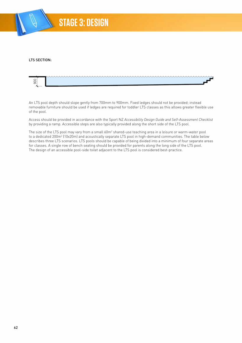
62
STAGE 3: DESIGN
LTS SECTION:
An LTS pool depth should slope gently from 700mm to 900mm. Fixed ledges should not be provided; instead removable furniture should be used if ledges are required for toddler LTS classes as this allows greater flexible use of the pool.
Access should be provided in accordance with the Sport NZ Accessibility Design Guide and Self-Assessment Checklist by providing a ramp. Accessible steps are also typically provided along the short side of the LTS pool.
The size of the LTS pool may vary from a small 60m2 shared-use teaching area in a leisure or warm-water pool to a dedicated 200m2 (10x20m) and acoustically separate LTS pool in high-demand communities. The table below describes three LTS scenarios. LTS pools should be capable of being divided into a minimum of four separate areas for classes. A single row of bench seating should be provided for parents along the long side of the LTS pool. The design of an accessible pool-side toilet adjacent to the LTS pool is considered best-practice.
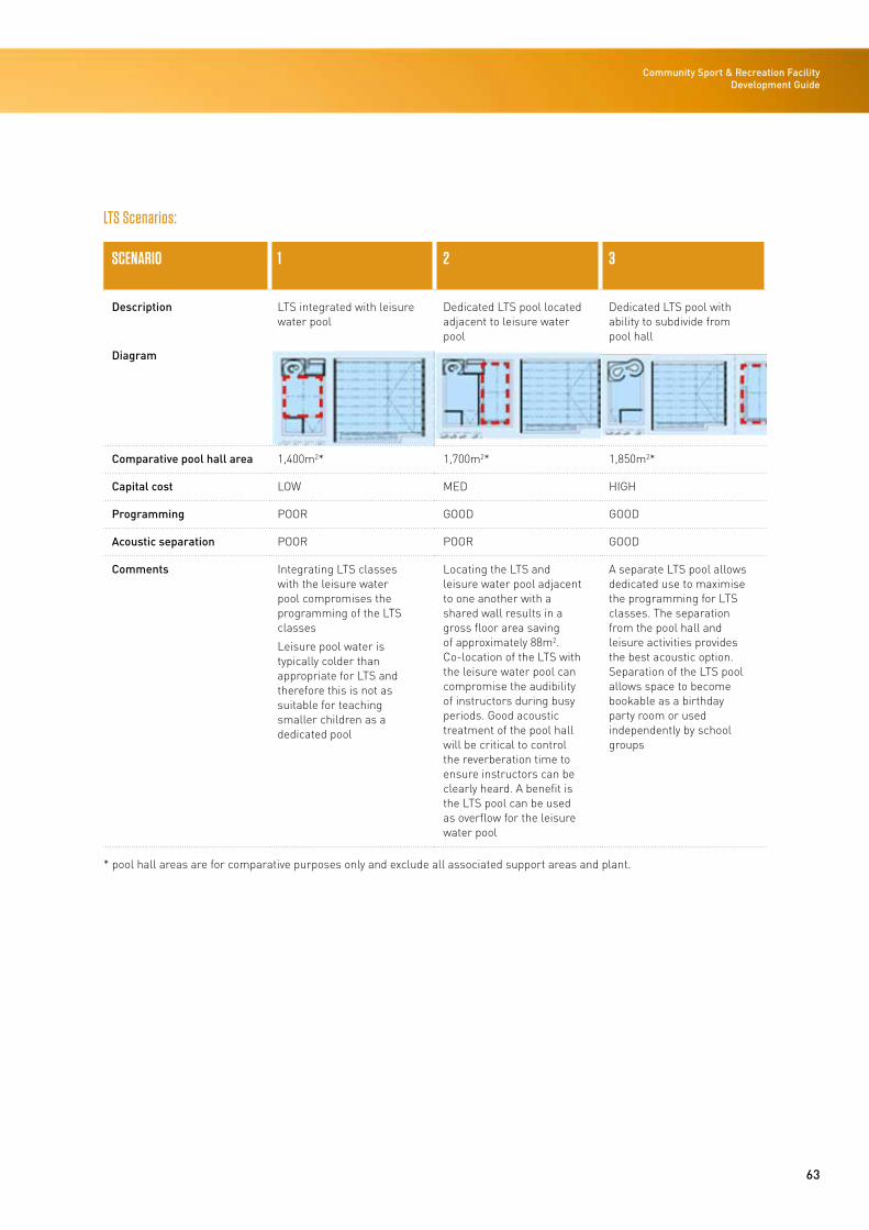
63
Community Sport & Recreation Facility Development Guide
LTS Scenarios:
SCENARIO 1 2 3
Description LTS integrated with leisure water pool
Dedicated LTS pool located adjacent to leisure water pool
Dedicated LTS pool with ability to subdivide from pool hall
Diagram
Comparative pool hall area 1,400m2* 1,700m2* 1,850m2*
Capital cost LOW MED HIGH
Programming POOR GOOD GOOD
Acoustic separation POOR POOR GOOD
Comments Integrating LTS classes with the leisure water pool compromises the programming of the LTS classes
Leisure pool water is typically colder than appropriate for LTS and therefore this is not as suitable for teaching smaller children as a dedicated pool
Locating the LTS and leisure water pool adjacent to one another with a shared wall results in a gross floor area saving of approximately 88m2. Co-location of the LTS with the leisure water pool can compromise the audibility of instructors during busy periods. Good acoustic treatment of the pool hall will be critical to control the reverberation time to ensure instructors can be clearly heard. A benefit is the LTS pool can be used as overflow for the leisure water pool
A separate LTS pool allows dedicated use to maximise the programming for LTS classes. The separation from the pool hall and leisure activities provides the best acoustic option. Separation of the LTS pool allows space to become bookable as a birthday party room or used independently by school groups
* pool hall areas are for comparative purposes only and exclude all associated support areas and plant.
64
STAGE 3: DESIGN
Programme Pool
A warm-water teaching pool, sometimes referred to as a ‘hydrotherapy pool’, typically caters to gentler programmes targeting slow-exercise injury rehabilitation to a mixture of young toddlers with parents, the mobility impaired and an older demographic. A warm-water pool is not typically a core component of a small community facility. The need to provide a dedicated warm-water programme pool must be driven by the needs analysis and investment objectives for the facility.
Accessible access should be provided in accordance with the Sport NZ Accessibility Design Guide and Self-Assessment Checklist by providing a ramp.
A warm-water pool where clinical hydrotherapy can be provided will benefit by proximity to healthcare providers. Consideration should be given to incorporating allied health and wellness treatment rooms as a way of introducing positive revenue streams to the facility. Warm-water-pool depths should vary from 1.4m in the shallow end to 1.5m for clinical hydrotherapy.
Leisure Pool
A typical community facility, aiming to target a large demographic and contribute positive revenue streams, must provide a variety of leisure, health and wellness components.
Leisure Components
Shallow leisure and recreation water can take many forms depending on the target market. Consideration must be given to the investment objectives and community demographic to identify the target audience. The table below illustrates a range of leisure components and categorises these by age group and whole-of-life cost.
The pricing policy should be considered as this will influence the selection and layout of leisure components.
A complementary analysis of surrounding facilities should be undertaken to determine the point of difference and therefore best mix of leisure components for a given community facility.
1-2 Year Age Group
Babies and toddlers should be provided with a separate safe, shallow and warm water area with a soft, resilient floor surface that is forgiving on children’s feet, hands and knees. Moving water such as bubble jets, weirs and interactive features may be provided with a beach entry.
3-7 Year Age Group
Young children should be provided with a variety of water depths and features. A combination of lazy rivers, zero-depth playground equipment, indoor slides, jets and sprays should be capable of being supplemented with inflatable toys and games. Leisure space should be designed to provide a range of spaces to cater to girls and boys.
7-12 Year Age Group
Older children require deeper water and are typically targeted through a combination of slides, inflatables, swings and balance obstacles. Visual effects and theming of the space can enable spaces to be re-invented.
Also refer to the water slides note below.
Teenage Age Group
Design to target the teenage market requires careful consideration to ensure the leisure space is flexible and can be re-invented. The most successful features are often informal spaces that can be reconfigured in a number of ways and can incorporate inflatables, bombing platforms, climbing walls, rope swings and zip lines. Many of these activities need deeper water and therefore require early consideration to include as part of the main lap pool design.
Water slides are a specialist area and a business case for these should be considered in the context of the surrounding facilities, the pricing policy and the objectives of the facility. There is a trend towards family, raft-type slides where multiple people can share the experience. Where these are to be considered a comparative analysis of throughput and storage space should be carried out.
Adult Age Group
Adult leisure trends cover a broad range of activities and spaces from relaxation to fitness. Key to attracting families to pools is the need to cater to the parents and this can be best achieved by providing a range of services in addition to the basic lap swimming, sauna, spa and lazy river offerings. Consider providing wellness services, massage, treatment rooms and a café.
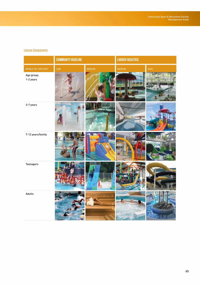
65
Community Sport & Recreation Facility Development Guide
Leisure Components
COMMUNITY BASELINE LARGER FACILITIES
WHOLE-OF-LIFE COST LOW MEDIUM MEDIUM HIGH
Age group:
1-2 years
3-7 years
7-12 years/family
Teenagers
Adults
66
STAGE 3: DESIGN
Innovative design and planning of the leisure water space will maximise its popularity and use. Cost need not be the primary driver of low-cost alternatives can add significant value, often with minimal or zero additional space allocation. Examples of features that have proved successful in community facilities are:
• Water features and dumping bucket
• Coloured lighting effects
• Water weirs
• Bombing platforms
• Indoor slides, rope swings, climbing walls.
Flexibility is key to allow the space to be re-invented once toys become old or outdated and to allow other pools within the facility to be converted to leisure during the school holidays. Standardised fixed water toy base plates and pump sizes allow toys to be interchanged. Pool-side power points should be in multiple locations to allow inflatable toys to be set up.
When incorporating interactive leisure features into the facility design consider:
Location and appropriateness of features and pools
• Water flow, circulation and treatment requirements
• Location and accessibility of controls and safety switches
• Accessibility for maintenance
• Ease of supervision and lifeguarding
• Impact upon other facility users
• Ability to be ‘closed’ to users
• Spare plant space capacity for pumps
• Future provision for in-ground pipes.
Note that water features, jets and sprays increase the humidity in the immediate area of the toys. Consideration should therefore be given to ensuring their separation from glass and other surfaces that are prone to condensation and there is good airflow around the pool water toys.
Consider providing space within plant rooms and casting in critical in-ground pipework to allow water slides to be added in future without impacting the base building. Anchor points at high levels allow zip lines and rope swings to be added at minimal cost if considered at the design stage.
While outdoor pools have been successful overseas the New Zealand climate, temperature and wind limit these facilities to seasonal use. A careful consideration of the prevailing wind direction, orientation and period of use is therefore needed to ensure the feasibility of outdoor pools.
Shallow leisure water, beach entries and zero-depth leisure facilitation should be located adjacent to the café and seating area. A café servery should service both the pool-side and the public foyer side if possible.
The table below describes three leisure facility projects in order of ascending scale. They successfully cater to a wide demographic and contribute positive revenue streams by providing a combination of toddler, child and adult leisure water components with health, fitness and retail facilities.
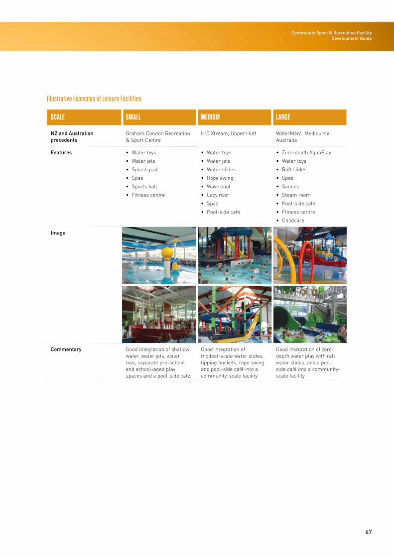
67
Community Sport & Recreation Facility Development Guide
Illustrative Examples of Leisure Facilities
SCALE SMALL MEDIUM LARGE
NZ and Australian precedents
Graham Condon Recreation & Sport Centre
H2O Xtream, Upper Hutt WaterMarc, Melbourne, Australia
Features • Water toys
• Water jets
• Splash pad
• Spas
• Sports hall
• Fitness centre
• Water toys
• Water jets
• Water slides
• Rope swing
• Wave pool
• Lazy river
• Spas
• Pool-side café
• Zero-depth AquaPlay
• Water toys
• Raft slides
• Spas
• Saunas
• Steam room
• Pool-side café
• Fitness centre
• Childcare
Image
Commentary Good integration of shallow water, water jets, water toys, separate pre-school and school-aged play spaces and a pool-side café
Good integration of modest-scale water slides, tipping buckets, rope swing and pool-side café into a community-scale facility
Good integration of zero-depth water play with raft water slides, and a pool-side café into a community-scale facility
68
STAGE 3: DESIGN
Leisure Pool
The leisure pool should have a minimum water surface area of 150m2 and the water depth should vary from 0mm to 1,200mm and provide ease of access for persons with disabilities or mobility difficulties. Depending on the design, size and dimensions selected for the main pool, additional space at 1.2m in this area may need to be considered to provide a range of structured fitness programmes and activities in water operated at a higher temperature.
This pool should provide outlets and equipment that facilitate interactive water play and fun activities that will be attractive to families and children. A minimum of six water features is recommended and these should be designed and installed in such a way that they are easily interchangeable. Features include moving water, small slides, geysers, fountains, pipes and waterfalls, spouts and sprays. The range of interactive water features should be developed to complement rather than compete with those provided elsewhere.
A separate balance tank, circulation and filtration system provided and roll-out and overflow channels flush with the concourse and separated from pool water flow return. Pool surfaces should be tiled and non-slip where people’s feet come in to contact with the pool floor. Given the nature of activity, a pool membrane safety surface such as the Natare pool system may be worthwhile. An area of spectator seating should be incorporated.
Spa, Steam and Sauna Areas
The provision of a family spa should be considered against the proposed pricing policy for the facility, as entry to spa, steam and sauna rooms can often be controlled and priced as an extra service. In a very small facility, cost-effective, off-the-shelf, proprietary or concourse solutions may be considered, although the limited lifespans of these products should be recognised and evaluated against more expensive options. Integrating a bubble jet/spa area with one end of the warm-water/programme pool can often be an innovative way of minimising the capital expenditure associated with providing a dedicated separate spa pool and filtration systems. Where a dedicated spa pool is provided it should have capacity for 15 people and be provided with ramped access in accordance with the Sport NZ Accessibility Design Guide and Self-Assessment Checklist. The spa should be located adjacent to the leisure pool and in close proximity to a cold pool-side shower.
Where steam or sauna rooms are provided, consider co-locating these adjacent to the spa area and warm-water pool to create an adult wellness area. Acoustic separation of a warm-water/adult wellness cluster should be considered.
Toddlers’ Pool
A toddlers’ pool adjacent to but physically separate from the shallow-water area of the leisure pool should have a water surface area of not less than 30m2 and vary in depth from 300mm to 400mm. As the pool is designed to cater for children under five years it should be easily accessible.
The pool should have its own balance tank, circulation and filtration system. Pool surfaces should be non-slip pool tiles of safety surface membrane.
Parent and caregiver seating should be located in close proximity to this pool.
Other Pool Users
It is not within the scope of this document to explore diving facilities. Diving demands deep water and is therefore very rarely compatible with community facilities. 1.8m-deep water would meet the minimum depth requirements for shallow diving and race starts.
Pool Change Facilities
The change room facility provision should be calculated in accordance with the Building Code Part G1 and benchmarked with similar community facilities. The following change areas should be provided:
• Separate family change rooms
• Separate male change rooms
• Separate female change rooms
• Dedicated accessible change room(s).
Preference should be given to:
• Separate shower cubicles within the male and female change areas instead of open shower areas
• A large, single, oversized accessible change room with enough space for three persons including a wheelchair instead of multiple smaller rooms. This accessible change room should be fitted with a fold-down, adjustable-height bed, hoist, accessible shower, WC and wash-hand basin. Refer to the Sport NZ Accessibility Design Guide and Self-Assessment Checklist

69
Community Sport & Recreation Facility Development Guide
• Maximising the number of family change rooms. A minimum of four family change rooms should be provided with preference for 8-12 in larger community facilities. This is often most efficiently achieved by minimising the size of family change rooms by providing a bench and change table only, and providing pool-side toilets and showers
• Providing a combination of open-sided lockers in the pool hall and secure lockers in the circulation spaces.
It is best-practice to provide separate dry access into, and wet access from, the main pool change rooms. The separation of a dry and wet change room entry process minimises the incidence of dirt migration into the pool hall by keeping shoes out of the wet areas and results in better hygiene and cleaning of the facility.
Facility examples that adopt a separate dry to wet change process include:
• Marlborough Lines Stadium 2000, Blenheim
• Selwyn Aquatic Centre, Christchurch
• Dudley Park Aquatic Centre, Rangiora.
Facility examples that adopt a pool hall wet change process include:
• Caroline Bay Trust Aoraki, Timaru
• Alpine Aqualand, Queenstown.
A reference facility change room layout from Marlborough Lines Stadium 2000 (Blenhiem):
Pool Storage
A wet equipment store both with direct access to the pool-side and external to the building should be provided. The minimum area for storage of pool equipment should be approximately 5 percent of the floor area of the pool hall. For example, if the pool hall is 2,000m2, a storeroom of 100m2 is required. The storage room should be well ventilated and provided with a drain and waterproof surfaces for wash-down.
Storage for pool covers should be provided in addition to the area noted above and must be accessible and easy to use by pool staff. Consider locations below seating or at a high level mounted on pool-side walls.
70
STAGE 3: DESIGN
Dry Sport ComponentsIndoor Sports Court
Indoor sports halls should cater to a wide demographic and seek to target a wide cross-section of indoor sports.
Indoor sports hall dimensions are typically governed within New Zealand by the size of indoor netball and basketball courts. Reference should be made to the relevant National Sport Organisations for court dimensions and run-off zones for typical sizes of indoor sports courts. Run-off zones provide adequate allowance for structural columns, scoring tables and perimeter bench seating to ensure these are positioned clearly outside the run-off zones.
While sports halls should be designed predominantly for sports activities, they can be used for a range of other non-sporting events and activities at periods of low demand to ensure the building is used as much as possible.
A clear height of 9m is required to play international-competition-level netball and volleyball and premier and international-level badminton. A lower clear height of 7.5m is typically considered sufficient in community facilities where community, club or premier-level sports are the focus. Clear heights should not be impeded by lights, radiant heating, retractable basketball hoops, nets or other fixtures, fittings and equipment (FF&E), and it is therefore important to allow sufficient tolerances above these clear heights.
The optimum arrangement of the indoor courts will be impacted by the intended spectator seating numbers, the overlay of alternative sports court markings and the number of courts proposed in the master plan. Two relevant facility examples that incorporate good-practice design and sustainability principles are the:
• ASB Sports Centre – Wellington
• ASB Arena – Tauranga.
The maximum number of spectators allowed in the sports hall for an event will be determined by the fire engineering design of the building. The ultimate use of the space must therefore be considered and clearly communicated in the client brief to the design team to ensure the building design can be adapted to accommodate the eventual anticipated spectator numbers. Three courts are considered a good configuration for an event court set-up due to the ability to configure the centre court as the main event court supported by retractable seating from the sides.
The cost per retractable seat excluding any increase in the size of the building is $550-$650 (excluding the building costs), depending on seat type and system selected.
Dry Sports Storage
A dry sports equipment store with direct access to the sports hall and external to the building should be provided in all facilities. This should be provided with power and data points to allow it to double as a kitchen preparation or plating area for other events. The minimum area of the dry storage room shall be 12.5 percent of the indoor courts’ floor area. Flush-fitting ‘up and over’ doors or roller shutters should be provided to give wide, unobstructed access from the dry storage area to the courts and outdoor delivery area.
Health and Fitness Centre
A health and fitness centre can be a successful complementary component of a community facility as it will contribute a positive revenue stream to the facility.
The fitness centre should be highly visible from the entry or foyer and from outside the facility. The location of the fitness centre will be determined by the particular site characteristics. On constrained sites it is typically located on the first floor where it can be provided with good visibility overlooking the pool hall. Careful consideration of acoustic issues is required where a fitness centre is located on the first floor. If the fitness centre is located on the ground floor it is often possible for it to share the sports hall change facilities.
A fitness centre should be considered in the smallest-scale community facilities, with a minimum size of 150m2, to provide a range of fitness equipment stations. Programme classes should be provided in the shared sports hall. A typical community facility should consider approximately 300m2 of fitness space, providing a mixture of equipment stations and aerobic exercise and fitness, room-based, programmes. Subject to catchment and local competition factors, a larger health and fitness centre with more stations will attract more ‘members’ and casual users, and improve the financial performance of the centre. A recommended area of 4.5m2 is suggested per fitness station.
Movement and dance studios may be included in larger fitness centres in association with open-plan cardio and weights fitness areas. This can increase the range on offer to the fitness ‘members’ and when combined with massage/treatment rooms can cater to the ‘wellness leisure’ sector of the community.
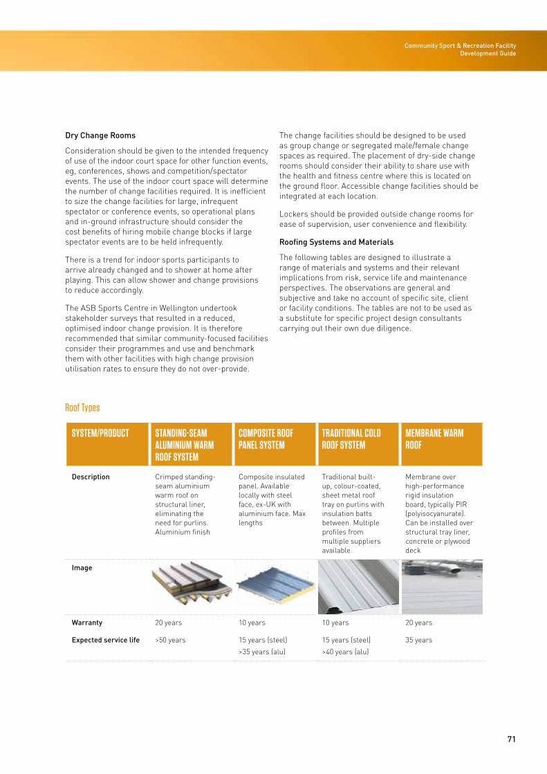
71
Community Sport & Recreation Facility Development Guide
Dry Change Rooms
Consideration should be given to the intended frequency of use of the indoor court space for other function events, eg, conferences, shows and competition/spectator events. The use of the indoor court space will determine the number of change facilities required. It is inefficient to size the change facilities for large, infrequent spectator or conference events, so operational plans and in-ground infrastructure should consider the cost benefits of hiring mobile change blocks if large spectator events are to be held infrequently.
There is a trend for indoor sports participants to arrive already changed and to shower at home after playing. This can allow shower and change provisions to reduce accordingly.
The ASB Sports Centre in Wellington undertook stakeholder surveys that resulted in a reduced, optimised indoor change provision. It is therefore recommended that similar community-focused facilities consider their programmes and use and benchmark them with other facilities with high change provision utilisation rates to ensure they do not over-provide.
The change facilities should be designed to be used as group change or segregated male/female change spaces as required. The placement of dry-side change rooms should consider their ability to share use with the health and fitness centre where this is located on the ground floor. Accessible change facilities should be integrated at each location.
Lockers should be provided outside change rooms for ease of supervision, user convenience and flexibility.
Roofing Systems and Materials
The following tables are designed to illustrate a range of materials and systems and their relevant implications from risk, service life and maintenance perspectives. The observations are general and subjective and take no account of specific site, client or facility conditions. The tables are not to be used as a substitute for specific project design consultants carrying out their own due diligence.
Roof Types
SYSTEM/PRODUCT STANDING-SEAM ALUMINIUM WARM ROOF SYSTEM
COMPOSITE ROOF PANEL SYSTEM
TRADITIONAL COLD ROOF SYSTEM
MEMBRANE WARM ROOF
Description Crimped standing-seam aluminium warm roof on structural liner, eliminating the need for purlins. Aluminium finish
Composite insulated panel. Available locally with steel face, ex-UK with aluminium face. Max lengths
Traditional built-up, colour-coated, sheet metal roof tray on purlins with insulation batts between. Multiple profiles from multiple suppliers available
Membrane over high-performance rigid insulation board, typically PIR (polyisocyanurate). Can be installed over structural tray liner, concrete or plywood deck
Image
Warranty 20 years 10 years 10 years 20 years
Expected service life >50 years 15 years (steel)
>35 years (alu)
15 years (steel)
>40 years (alu)
35 years
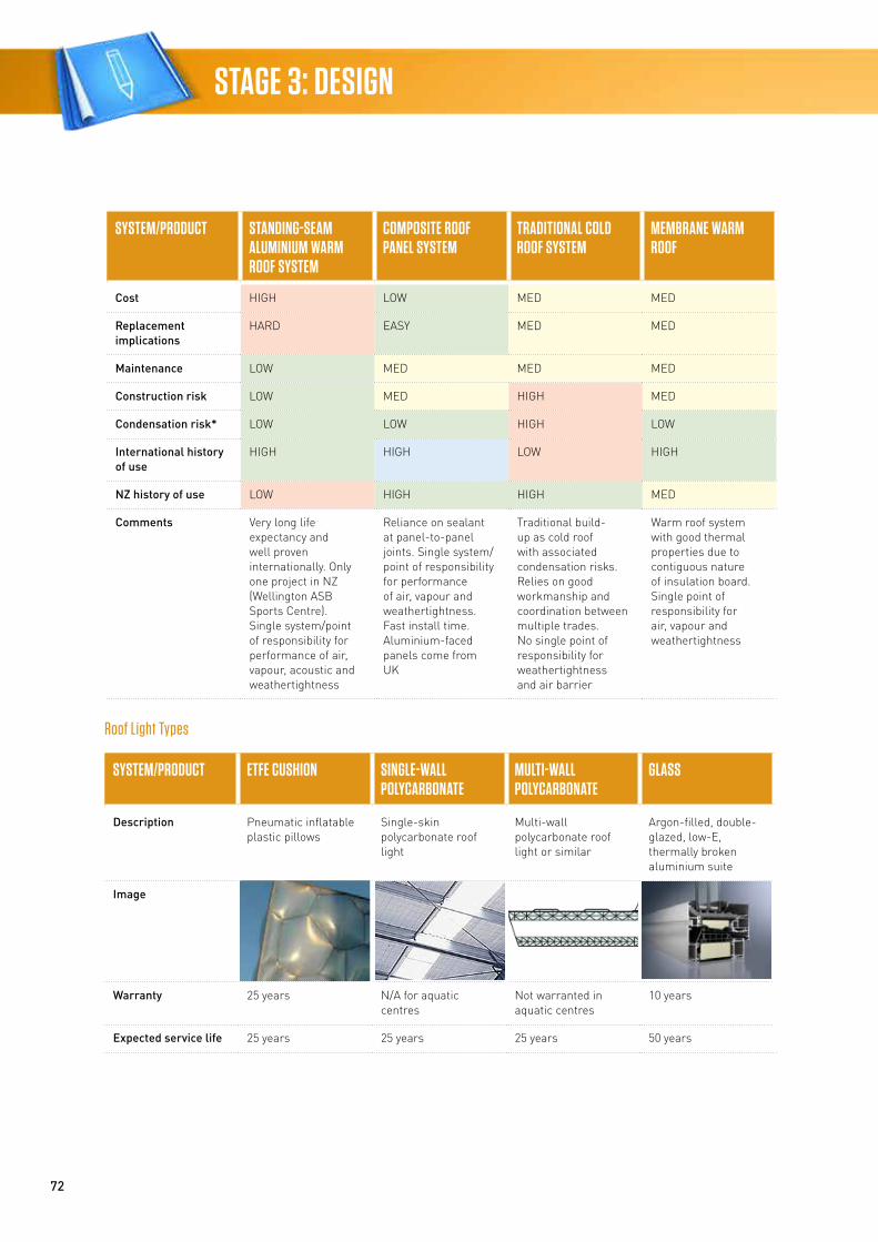
72
STAGE 3: DESIGN
SYSTEM/PRODUCT STANDING-SEAM ALUMINIUM WARM ROOF SYSTEM
COMPOSITE ROOF PANEL SYSTEM
TRADITIONAL COLD ROOF SYSTEM
MEMBRANE WARM ROOF
Cost HIGH LOW MED MED
Replacement implications
HARD EASY MED MED
Maintenance LOW MED MED MED
Construction risk LOW MED HIGH MED
Condensation risk* LOW LOW HIGH LOW
International history of use
HIGH HIGH LOW HIGH
NZ history of use LOW HIGH HIGH MED
Comments Very long life expectancy and well proven internationally. Only one project in NZ (Wellington ASB Sports Centre). Single system/point of responsibility for performance of air, vapour, acoustic and weathertightness
Reliance on sealant at panel-to-panel joints. Single system/ point of responsibility for performance of air, vapour and weathertightness. Fast install time. Aluminium-faced panels come from UK
Traditional build-up as cold roof with associated condensation risks. Relies on good workmanship and coordination between multiple trades. No single point of responsibility for weathertightness and air barrier
Warm roof system with good thermal properties due to contiguous nature of insulation board. Single point of responsibility for air, vapour and weathertightness
Roof Light Types
SYSTEM/PRODUCT ETFE CUSHION SINGLE-WALL POLYCARBONATE
MULTI-WALL POLYCARBONATE
GLASS
Description Pneumatic inflatable plastic pillows
Single-skin polycarbonate roof light
Multi-wall polycarbonate roof light or similar
Argon-filled, double-glazed, low-E, thermally broken aluminium suite
Image
Warranty 25 years N/A for aquatic centres
Not warranted in aquatic centres
10 years
Expected service life 25 years 25 years 25 years 50 years
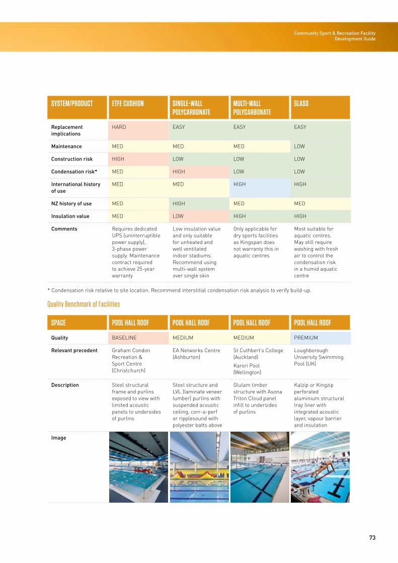
73
Community Sport & Recreation Facility Development Guide
SYSTEM/PRODUCT ETFE CUSHION SINGLE-WALL POLYCARBONATE
MULTI-WALL POLYCARBONATE
GLASS
Replacement implications
HARD EASY EASY EASY
Maintenance MED MED MED LOW
Construction risk HIGH LOW LOW LOW
Condensation risk* MED HIGH LOW LOW
International history of use
MED MED HIGH HIGH
NZ history of use MED HIGH MED MED
Insulation value MED LOW HIGH HIGH
Comments Requires dedicated UPS (uninterruptible power supply), 3-phase power supply. Maintenance contract required to achieve 25-year warranty
Low insulation value and only suitable for unheated and well ventilated indoor stadiums. Recommend using multi-wall system over single skin
Only applicable for dry sports facilities as Kingspan does not warranty this in aquatic centres
Most suitable for aquatic centres. May still require washing with fresh air to control the condensation risk in a humid aquatic centre
* Condensation risk relative to site location. Recommend interstitial condensation risk analysis to verify build-up.
Quality Benchmark of Facilities
SPACE POOL HALL ROOF POOL HALL ROOF POOL HALL ROOF POOL HALL ROOF
Quality BASELINE MEDIUM MEDIUM PREMIUM
Relevant precedent Graham Condon Recreation & Sport Centre (Christchurch)
EA Networks Centre (Ashburton)
St Cuthbert’s College (Auckland)
Karori Pool (Wellington)
Loughborough University Swimming Pool (UK)
Description Steel structural frame and purlins exposed to view with limited acoustic panels to undersides of purlins
Steel structure and LVL (laminate veneer lumber) purlins with suspended acoustic ceiling, corr-a-perf or ripplesound with polyester batts above
Glulam timber structure with Asona Triton Cloud panel infill to undersides of purlins
Kalzip or Kingzip perforated aluminium structural tray liner with integrated acoustic layer, vapour barrier and insulation
Image
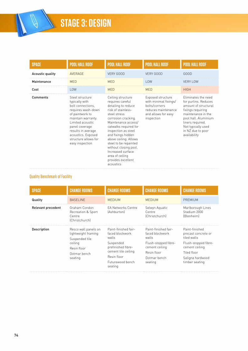
74
STAGE 3: DESIGN
SPACE POOL HALL ROOF POOL HALL ROOF POOL HALL ROOF POOL HALL ROOF
Acoustic quality AVERAGE VERY GOOD VERY GOOD GOOD
Maintenance MED MED LOW VERY LOW
Cost LOW MED MED HIGH
Comments Steel structure typically with bolt connections, requires wash-down of paintwork to maintain warranty. Limited acoustic panel coverage results in average acoustics. Exposed structure allows for easy inspection
Ceiling structure requires careful detailing to reduce risk of stainless-steel stress corrosion cracking. Maintenance access/ catwalks required for inspection as steel and fixings hidden above ceiling. Allows steel to be repainted without closing pool. Increased surface area of ceiling provides excellent acoustics
Exposed structure with minimal fixings/ bolts/corners reduces maintenance and allows for easy inspection
Eliminates the need for purlins. Reduces amount of structural fixings requiring maintenance in the pool hall. Aluminium liners required. Not typically used in NZ due to poor availability
Quality Benchmark of Facility
SPACE CHANGE ROOMS CHANGE ROOMS CHANGE ROOMS CHANGE ROOMS
Quality BASELINE MEDIUM MEDIUM PREMIUM
Relevant precedent Graham Condon Recreation & Sport Centre (Christchurch)
EA Networks Centre (Ashburton)
Selwyn Aquatic Centre (Christchurch)
Marlborough Lines Stadium 2000 (Blenheim)
Description Resco wall panels on lightweight framing
Suspended tile ceiling
Resin floor
Dotmar bench seating
Paint-finished fair-faced blockwork walls
Suspended prefinished fibre-cement tile ceiling
Resin floor
Futurewood bench seating
Paint-finished fair-faced blockwork walls
Flush-stopped fibre-cement ceiling
Resin floor
Dotmar bench seating
Paint-finished precast concrete or tiled walls
Flush-stopped fibre-cement ceiling
Tiled floor
Saligna hardwood timber seating
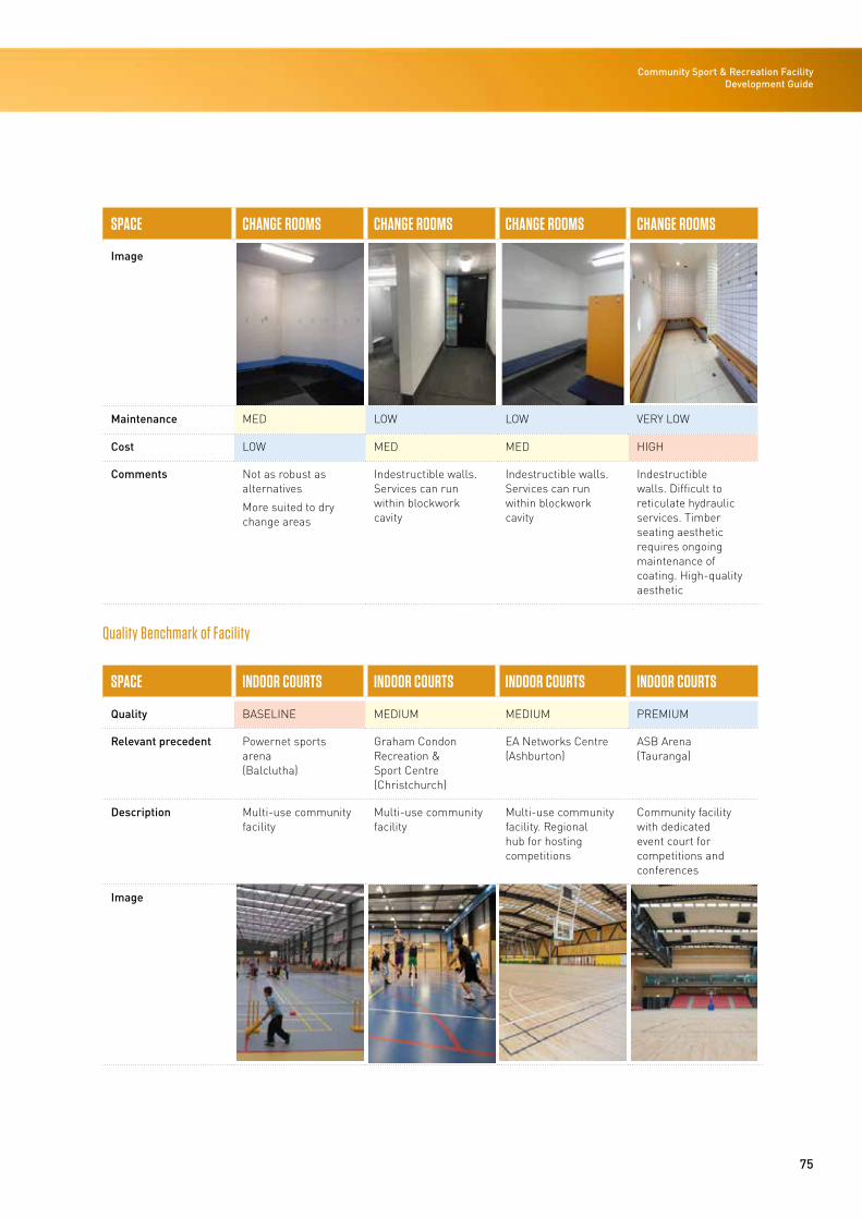
75
Community Sport & Recreation Facility Development Guide
SPACE CHANGE ROOMS CHANGE ROOMS CHANGE ROOMS CHANGE ROOMS
Image
Maintenance MED LOW LOW VERY LOW
Cost LOW MED MED HIGH
Comments Not as robust as alternatives
More suited to dry change areas
Indestructible walls. Services can run within blockwork cavity
Indestructible walls. Services can run within blockwork cavity
Indestructible walls. Difficult to reticulate hydraulic services. Timber seating aesthetic requires ongoing maintenance of coating. High-quality aesthetic
Quality Benchmark of Facility
SPACE INDOOR COURTS INDOOR COURTS INDOOR COURTS INDOOR COURTS
Quality BASELINE MEDIUM MEDIUM PREMIUM
Relevant precedent Powernet sports arena (Balclutha)
Graham Condon Recreation & Sport Centre (Christchurch)
EA Networks Centre (Ashburton)
ASB Arena (Tauranga)
Description Multi-use community facility
Multi-use community facility
Multi-use community facility. Regional hub for hosting competitions
Community facility with dedicated event court for competitions and conferences
Image
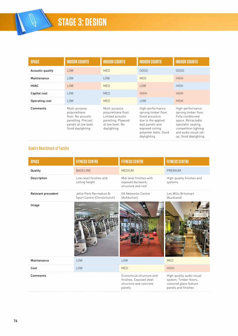
76
STAGE 3: DESIGN
SPACE INDOOR COURTS INDOOR COURTS INDOOR COURTS INDOOR COURTS
Acoustic quality LOW MED GOOD GOOD
Maintenance LOW LOW MED HIGH
HVAC LOW MED LOW HIGH
Capital cost LOW MED HIGH HIGH
Operating cost LOW MED LOW HIGH
Comments Multi-purpose polyurethane floor. No acoustic panelling. Precast panels at low level. Good daylighting
Multi-purpose polyurethane floor. Limited acoustic panelling. Plywood at low level. No daylighting
High-performance sprung timber floor. Good acoustics due to the applied wall panels and exposed ceiling polyester batts. Good daylighting
High-performance sprung timber floor. Fully conditioned space. Retractable spectator seating, competition lighting and audio visual set-up. Good daylighting
Quality Benchmark of Facility
SPACE FITNESS CENTRE FITNESS CENTRE FITNESS CENTRE
Quality BASELINE MEDIUM PREMIUM
Description Low-level finishes and ceiling height
Mid-level finishes with exposed ductwork, structure and roof
High-quality finishes and systems
Relevant precedent Jellie Park Recreation & Sport Centre (Christchurch)
EA Networks Centre (Ashburton)
Les Mills Britomart (Auckland)
Image
Maintenance LOW LOW MED
Cost LOW MED HIGH
Comments Economical structure and finishes. Exposed steel structure and concrete panels
High-quality audio visual system. Timber floors, coloured glass feature panels and finishes
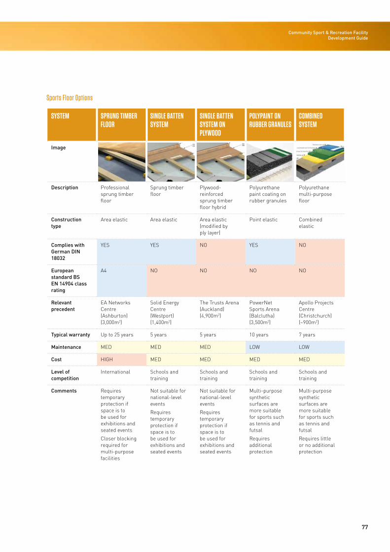
77
Community Sport & Recreation Facility Development Guide
Sports Floor Options
SYSTEM SPRUNG TIMBER FLOOR
SINGLE BATTEN SYSTEM
SINGLE BATTEN SYSTEM ON PLYWOOD
POLYPAINT ON RUBBER GRANULES
COMBINED SYSTEM
Image
Description Professional sprung timber floor
Sprung timber floor
Plywood-reinforced sprung timber floor hybrid
Polyurethane paint coating on rubber granules
Polyurethane multi-purpose floor
Construction type
Area elastic Area elastic Area elastic (modified by ply layer)
Point elastic Combined elastic
Complies with German DIN 18032
YES YES NO YES NO
European standard BS EN 14904 class rating
A4 NO NO NO NO
Relevant precedent
EA Networks Centre (Ashburton) (3,000m2)
Solid Energy Centre (Westport) (1,400m2)
The Trusts Arena (Auckland)(4,900m2)
PowerNet Sports Arena (Balclutha) (3,500m2)
Apollo Projects Centre (Christchurch) (~900m2)
Typical warranty Up to 25 years 5 years 5 years 10 years 7 years
Maintenance MED MED MED LOW LOW
Cost HIGH MED MED MED MED
Level of competition
International Schools and training
Schools and training
Schools and training
Schools and training
Comments Requires temporary protection if space is to be used for exhibitions and seated events
Closer blocking required for multi-purpose facilities
Not suitable for national-level events
Requires temporary protection if space is to be used for exhibitions and seated events
Not suitable for national-level events
Requires temporary protection if space is to be used for exhibitions and seated events
Multi-purpose synthetic surfaces are more suitable for sports such as tennis and futsal
Requires additional protection
Multi-purpose synthetic surfaces are more suitable for sports such as tennis and futsal
Requires little or no additional protection
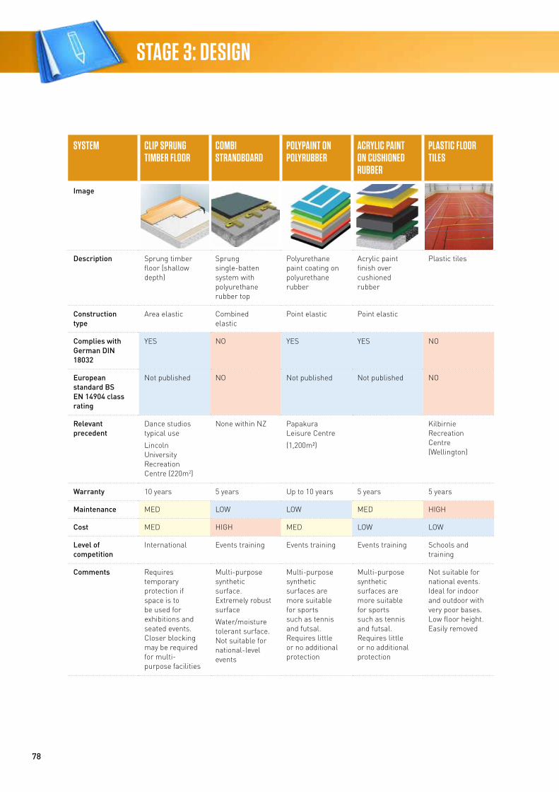
78
STAGE 3: DESIGN
SYSTEM CLIP SPRUNG TIMBER FLOOR
COMBI STRANDBOARD
POLYPAINT ON POLYRUBBER
ACRYLIC PAINT ON CUSHIONED RUBBER
PLASTIC FLOOR TILES
Image
Description Sprung timber floor (shallow depth)
Sprung single-batten system with polyurethane rubber top
Polyurethane paint coating on polyurethane rubber
Acrylic paint finish over cushioned rubber
Plastic tiles
Construction type
Area elastic Combined elastic
Point elastic Point elastic
Complies with German DIN 18032
YES NO YES YES NO
European standard BS EN 14904 class rating
Not published NO Not published Not published NO
Relevant precedent
Dance studios typical use
Lincoln University Recreation Centre (220m2)
None within NZ Papakura Leisure Centre
(1,200m²)
Kilbirnie Recreation Centre (Wellington)
Warranty 10 years 5 years Up to 10 years 5 years 5 years
Maintenance MED LOW LOW MED HIGH
Cost MED HIGH MED LOW LOW
Level of competition
International Events training Events training Events training Schools and training
Comments Requires temporary protection if space is to be used for exhibitions and seated events. Closer blocking may be required for multi-purpose facilities
Multi-purpose synthetic surface. Extremely robust surface
Water/moisture tolerant surface. Not suitable for national-level events
Multi-purpose synthetic surfaces are more suitable for sports such as tennis and futsal. Requires little or no additional protection
Multi-purpose synthetic surfaces are more suitable for sports such as tennis and futsal. Requires little or no additional protection
Not suitable for national events. Ideal for indoor and outdoor with very poor bases. Low floor height. Easily removed
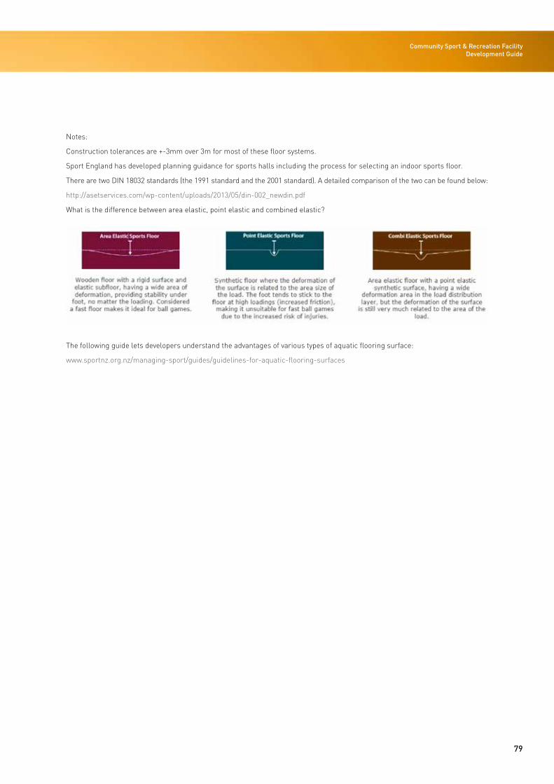
79
Community Sport & Recreation Facility Development Guide
Notes:
Construction tolerances are +-3mm over 3m for most of these floor systems.
Sport England has developed planning guidance for sports halls including the process for selecting an indoor sports floor.
There are two DIN 18032 standards (the 1991 standard and the 2001 standard). A detailed comparison of the two can be found below:
http://asetservices.com/wp-content/uploads/2013/05/din-002_newdin.pdf
What is the difference between area elastic, point elastic and combined elastic?
The following guide lets developers understand the advantages of various types of aquatic flooring surface:
www.sportnz.org.nz/managing-sport/guides/guidelines-for-aquatic-flooring-surfaces
80
STAGE 3: DESIGN
Acoustics
Introduction
A community sports facility must have appropriate acoustic conditions for its intended use. Participants, spectators and staff all benefit from sufficiently low background noise levels, as they make verbal communication easier to understand. This is especially critical for people with hearing impairments or learning difficulties, and also for training, teaching/learning situations and activities that are accompanied by music.
Compliance with district plan noise standards must also be achieved, or an appropriate case put forward to obtain consent to exceed those standards.
The acoustic conditions inside a community sports facility must be appropriate for the intended use. It is beneficial to all users that ambient noise levels are appropriately controlled and that verbal communication is easily intelligible, being especially critical for people with hearing impairments or learning difficulties. This is particularly important for training, teaching/learning situations and activities that are accompanied by music.
To achieve appropriate ambient noise levels and good speech intelligibility, the control of reverberation is a key factor. Another important factor is to achieve an appropriate reduction in noise intrusion from both outside the building and other spaces within the building such as plant rooms, fitness rooms and change rooms.
Reverberation Control
The acoustic quality of a room is most commonly described by its reverberation time. The reverberation time of a room is the time (in seconds) taken for an instantaneous sound event to decay by 60dB.
A room with a long reverberation time of several seconds will cause syllables to be prolonged so that they overlap and degrade speech intelligibility. Long reverberation times occur in large rooms with hard wall and ceiling surfaces. Adding sound-absorbent and diffusive materials will reduce the reverberation time and improve speech intelligibility.
Long reverberation times also increase the noise level within a room, which further decreases speech intelligibility. To compensate for this, people tend to increase their voice levels to make themselves heard over the reverberant noise, which further exacerbates the situation. This is a common feature of many community sports facilities with insufficient sound-absorbent surfaces.
To ensure that the reverberation times within a community sports facility are adequately controlled, design criteria and recommended locations of acoustic treatment are provided in Section 4 Build.
Internal Noise Levels
Elevated levels of noise within a community sports facility will cause greater masking of speech and therefore decrease intelligibility. It is possible to speak louder, but this effect is limited and can also lead to voice strain.
The two principal sources of noise within a community sports facility are likely to be external noise intrusion and noise from mechanical ventilation and building services. External noise intrusion is governed by the sound insulation of the building fabric and site conditions such as proximity to major roads and other sources of noise. Noise from mechanical ventilation and building services is dependent on the systems utilised. Design criteria for these sources are provided in Section 4 Build.
Acoustic Separation Between Spaces
The provision of appropriate internal sound insulation, separating spaces that generate high levels of noise from those sensitive to noise intrusion, is important. Examples of spaces capable of generating high levels of noise are:
• Sports/pool halls
• Plant rooms
• Dance/fitness rooms
• Change rooms.
It is good practice, wherever possible, to separate these spaces from noise-sensitive receivers with buffer zones such as circulation spaces/corridors and storage areas. In most cases in these facilities, high-noise-level areas are separated in such a way. One direct adjacency that should be considered, however, is between the plant room and sports/pool halls. The primary aim should be to select plant with low noise-level emissions wherever possible. Once the plant has been selected, the appropriate sound insulation of the separating wall should be chosen to achieve the required noise criterion within the hall.
81
Community Sport & Recreation Facility Development Guide
Control of External Noise Intrusion
Appropriate isolation from external noise sources such as traffic is desirable to minimise distraction and to create a comfortable environment. This is typically gained by assessing the external noise environment to determine the sound insulation performance of the building envelope necessary to achieve the internal noise-level criteria (refer Section 4– Build).
Other important considerations are noise generated from rainfall (discussed in Section 4 Build) and noise breakout from the facility to noise-sensitive neighbours. Designing the building envelope to control noise breakout depends on the proximity of noise-sensitive neighbours, the activities proposed to take place within the facility, operating hours etc. Further information on environmental noise limits is provided in the following section.
Planning Considerations
A community sports facility is usually required to meet environmental noise standards contained in the local district plan. These noise standards will vary depending on the zoning of the site and adjacent properties set out in the district plan.
Vehicle movements, external mechanical plant and outdoor activities are the primary sources of noise that usually require consideration. Generally, noise barriers such as earth bunds and solid fences can be used to mitigate noise from these sources effectively. Engaging a planning professional at an early stage to identify compliance requirements with local environmental noise standards is recommended.
Hosting amplified music events such as functions, wedding receptions and discos can sometimes be considered as an alternative income stream. However, the special design requirements necessary for such events to comply with relevant noise standards are generally not practicable for community sports facilities.
CivilThe following types of drainage need to be carefully considered in the civil engineering design of any facility:
• Stormwater
• Wastewater
• Foul water.
The design of any drainage systems needs to meet the requirements set out in relevant design standards and codes, and also meet the special requirements of local authorities.
Below-Ground Drainage
Detailed discussions will be required with the local territorial authority to establish the constraints for the drainage design.
The ability to discharge water to a public network depends on the location and invert of the network pipes relative to the site information, which can readily be obtained from the local authority. Important considerations include whether the site can drain by gravity or if a pumping station will be required.
The local authority can typically provide confirmation of the available capacity in the system to service the development.
a. Stormwater
The main issues with the surface-water drainage design will be common to those for any large building, ie, the volume of flow associated with:
• Run-off from carpark and other hardstand areas
• Roof drainage.
Depending on the site and surrounding drainage infrastructure, surface water may discharge:
• To a public stormwater system
• To a water body/river
• By infiltration to ground via soak pits (depending on ground conditions)
• Via a combination of the above.
If soak pits are used to dissipate surface-water flows, consideration must be given to future ground water levels and how these might affect the potential for floatation of the underground tanks.
82
STAGE 3: DESIGN
b. Wastewater
Similar to stormwater drainage, the wastewater typically drains to a public network and similar considerations are required.
c. Foul Water
Foul water discharge may require a specific consent.
Structural
General Structural Considerations
Design life – 50 years is the typically adopted design life for new structures.
Importance level – new structures are designated an ‘importance level’, which helps to determine the various structural loadings that buildings are designed for. The importance level adopted for new buildings can depend on various factors, such as the number of occupants, size, use and post-disaster requirements. The importance level for sport and recreation facilities would most often be determined by the number of occupants who could congregate in a single area. A typical sport and recreation facility with areas where more than 300 occupants can congregate would be designed to importance level 3.
Limit states – new structures are required to be designed to two different levels defined below:
• Serviceability limit state (SLS) – considers the day-to-day loadings on the structure. Under this level of loading there should be no damage to the structure, and any deflections or vibrations of the structure would not be noticeable
• Ultimate limit state (ULS) – considers the life safety of the structure. Under this level of loading there could be significant damage to the structure and it may not be usable again, but there would be no collapse of the structure (or parts of it), allowing occupants to escape safely.
Structural Design Standards
There are a number of codes and standards that need to be considered for the design of new buildings and swimming pool structures. It is expected that a competent design consultancy would be abreast of these required standards and would be able to apply them appropriately given the specific considerations of the chosen site.
We note that the facility owner may elect to have the building structures designed to a level greater than the minimum specified in the relevant codes and standards. This may depend on the specific conditions of and relative risks associated with each site. A competent design consultant can comment and make recommendations on this for each site as appropriate.
Structural Design Loading
The following describes typical structural loadings that are required to be considered for the design of new structures. Design loads will need to be assessed for each project to take into account specific site conditions and building materials.
Permanent and Imposed Loadings
Gravity loads – includes all permanent material elements of the structure and building such as structural self-weight, building fabric, suspended services and ceilings and plant weight. The gravity load is calculated on a case-by-case basis depending on the type of building, its size and the types of materials.
Imposed loads – includes non-permanent or transient loads such as furniture, non-permanent partitions and people. The imposed loads vary depending on the use of the area, and are typically referred to as ‘live loads’.
Variable loadings – snow, wind and earthquake loading will vary between sites throughout New Zealand and will therefore need to be assessed on a site-specific basis. A sites with a high snow, wind or earthquake loading will normally require an increase in the size of the structure to resist the higher loading.
The images below give an indication of the variability of snow, wind and earthquake loading throughout New Zealand. Red indicates a high-load zone, blue medium and yellow low. Site-specific design loadings will need to be determined for each facility on a case-by-case basis.
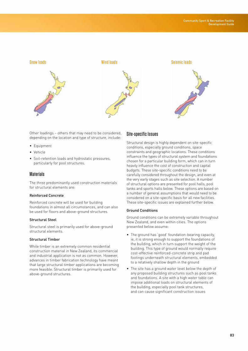
83
Community Sport & Recreation Facility Development Guide
Snow loads Wind loads Seismic loads
Other loadings – others that may need to be considered, depending on the location and type of structure, include:
• Equipment
• Vehicle
• Soil-retention loads and hydrostatic pressures, particularly for pool structures.
Materials
The three predominantly used construction materials for structural elements are:
Reinforced Concrete
Reinforced concrete will be used for building foundations in almost all circumstances, and can also be used for floors and above-ground structures.
Structural Steel
Structural steel is primarily used for above-ground structural elements.
Structural Timber
While timber is an extremely common residential construction material in New Zealand, its commercial and industrial application is not as common. However, advances in timber fabrication technology have meant that large structural timber applications are becoming more feasible. Structural timber is primarily used for above-ground structures.
Site-specific Issues
Structural design is highly dependent on site-specific conditions, especially ground conditions, space constraints and geographic locations. These conditions influence the types of structural system and foundations chosen for a particular building form, which can in turn heavily influence the cost of construction and capital budgets. These site-specific conditions need to be carefully considered throughout the design, and even at the very early stages such as site selection. A number of structural options are presented for pool halls, pool tanks and sports halls below. These options are based on a number of general assumptions that would need to be considered on a site-specific basis for all new facilities. These site-specific issues are explained further below.
Ground Conditions
Ground conditions can be extremely variable throughout New Zealand, and even within cities. The options presented below assume:
• The ground has ‘good’ foundation-bearing capacity, ie, it is strong enough to support the foundations of the building, which in turn support the weight of the building. This type of ground would normally require cost-effective reinforced-concrete strip and pad footings underneath structural elements, embedded to a relatively shallow depth in the ground
• The site has a ground water level below the depth of any proposed building structures such as pool tanks and foundations. A site with a high water table can impose additional loads on structural elements of the building, especially pool tank structures, and can cause significant construction issues
84
STAGE 3: DESIGN
• Liquefaction of the ground is not likely to occur during an earthquake. Liquefaction is a phenomenon that occurs when a site has a combination of a high water table and a loose, sandy-type soil when earthquake shaking occurs. Liquefaction can cause the ground to lose its strength, causing heavy structures (such as buildings) to sink, and light structures (such as in-ground pools and pipes) to become buoyant. As an example, widespread liquefaction occurred during the Canterbury earthquakes in 2010 and 2011, causing significant damage to many buildings and the below-ground infrastructure throughout the city.
It is strongly recommended that a geotechnical engineer be engaged to prepare a report on the ground conditions before any prospective site is purchased. Unfavourable ground conditions can lead to a significant increase in cost for a new sport and recreation facility.
Building Size and Shape
The options presented below assume that the building is similar in size and shape to the reference facility (linear model) presented in this document:
• Relatively rectangular in shape
• Larger hall areas for the pool hall and sports courts, with lower-level ancillary areas for administration, plant rooms, change areas, storage and fitness areas
• The overall site is flat and has relatively generous space so that construction areas can be easily accommodated.
Other sites may be more space constrained and require more compact building arrangements requiring alternative types, or a mix, of building structures.
Many of the options presented are still applicable to different shapes and sizes building, but any influence of this would need to be considered by the design consultant on a case-by-case basis. Other options may be considered depending on the size, shape and use of the facility.
Sports Hall
Layout
Sports halls typically require relatively long-span structures to avoid columns disrupting court areas, and need to be high enough so that the roof structures do not impede the variety of sports that are often played in indoor court areas.
Structural Elements
Floor
The ground-floor structure for the sports hall would typically be a reinforced-concrete slab supported on the ground. This slab would need to be compatible with the chosen type of sports floor.
In some cases where the ground is good and a timber floor is chosen, this could be supported by a grid of short jack studs supported off the ground.
In cases where the ground is poor, the ground-floor structure may become integrated with the foundation system, in the form of a structural raft across the entire building footprint.
Some sports equipment, such as posts and goals, requires deep sockets within the floor slab. These are to enable the sports equipment to be put up and taken down as required to provide a flush floor surface when not in use. Localised foundations may be required for these specific locations and specific design will be required depending on the type of equipment needed.
Regardless of the specific site foundation requirements, special attention is needed to minimise potential cold bridging and to coordinate the floor structure with the foundations, the chosen sports floor, and any special sports equipment supports.
85
Community Sport & Recreation Facility Development Guide
Roof Structure
The roof structure typically comprises a lightweight cladding material supported on a series of purlins that are, in turn, supported by the main structural frame of the building.
The purlins could comprise either lightweight steel or timber, but lightweight steel is more commonly used due to its greater span capability.
The purlins would typically be designed to support any building services suspended from the roof structure such as air-conditioning ductwork, lights and fire sprinklers. Other suspended items such as sports equipment would need to be considered and designed for on a case-by-case basis.
Walls
The wall cladding could comprise a number of different elements depending on the project-specific requirements. Structural elements of the walls are typically supported by the main building frame, and will need to be designed to support the cladding elements of the building and any sports equipment that needs to be fixed to the walls.
Wall structural elements could comprise lightweight steel girts supporting a light cladding, timber-framed walls or reinforced concrete panels depending on various requirements.
Ancillary Areas
Ancillary areas of the building vary in size and include change rooms, entrance lobbies, storage areas, plant rooms, staff areas, fitness studios and the like. These areas are integral to the main structure, although they are typically lower in height.
These areas could be constructed from structural solutions similar to those outlined in the table below, and they would typically be structurally connected to the main sports hall structure.
Other Specific Considerations
Maintenance Issues
Special consideration should be given during the design to enable the structural elements, and the elements they support (such as suspended services), to be easily accessible for inspection and maintenance if necessary.
Suspended Structures
Depending on the layout of the building, some suspended structures may be required. These structures could be in the form of mezzanine floors for plant areas or raised fitness studios. These areas would need to be considered on a case-by-case basis, with special consideration given to the structural layout to support the suspended floor and vibration of the floor if used for a fitness studio or similar activities.
Pool Hall
Layout
Pool halls typically require long-span structures to avoid columns disrupting pool areas, and need to be of moderate height to maintain the feeling of space and control humidity without having an uneconomical volume of air to heat/cooling.
The design of the building structures also needs to take into account the life span of the structure in conjunction with other elements of the building. In particular, it should be noted that the mechanical and electrical installations will probably have much shorter lives and full replacement might be expected at, say, 20-25 years. Ideally, the structural layout of the building should be designed to facilitate this.
Early Design Considerations
In addition to the above, swimming pool buildings are very highly serviced with traditional mechanical and electrical installations, filtration equipment, associated balance tanks and distribution pipework, and specialist equipment associated with any competition use of the pool, eg, timing pads, movable floors and booms, underwater sound, lighting and cameras etc. Early meetings must take place with the client together with specialist consultants and sub-contractors to determine the effects that these elements could have on the structure and therefore cost. Accessibility requirements also need to be considered at the very early stages so that requirements can be incorporated into the pool tank arrangements.
Structural Elements
Floor
Care must be taken to allow room for the building foundations to be constructed without impeding the swimming pool tank areas.
86
STAGE 3: DESIGN
Other Specific Considerations
Durability Maintenance Issues
Pool halls typically have very harsh, corrosive environments and special consideration should be given during the design to enable the structural elements, and the elements they support (such as suspended services), to be easily accessible for inspection and maintenance.
Care must be taken in the detailing of pool hall structures to avoid areas that could lead to the early onset of corrosion. Some examples of special considerations are:
• Where possible, use hollow steel sections without sharp edges
• Columns in wet areas should be supported off a concrete nib that sits above floor level
• Concrete surfaces that meet steel elements should slope away from the steel elements to avoid moisture ponding against the steel elements
• A carefully considered paint system is required that is appropriate for the highly corrosive atmosphere
• All gaps and joints should be sealed with a suitable flexible sealant – careful consideration in the selection of sealants is required as many react with chlorine, leading to early failure
• Any suspended structures should be carefully detailed to limit potential corrosion or condensation that may not be readily visible.
Stainless Steel and Galvanising in Swimming Pools
In general, stainless-steel should not be used for any structural application in swimming pools and associated wet areas without a very careful consideration of the grade used and the detailing of the proposed sections. Stainless steel is susceptible to stress corrosion cracking in warm, chlorine-laden atmospheres. This can cause rapid strength loss and sudden failure in members, in particular a failure of suspension hangers acting in tension. It should also be noted that stainless-steel exposed to a chlorine environment will stain with rust quickly if not cleaned on a daily basis. Note that stainless-steel is often used in structural situations where the structural engineer would not normally be consulted, eg, suspension rods for mechanical services, ceiling suspension systems, glazing brackets and wall ties/restraints, and similar considerations will apply.
Galvanising can readily be used in a pool atmosphere, but like stainless-steel it is prone to staining if not cleaned. Detailing of the galvanised steel is important in wet areas, as loss of galvanising can occur where metals with different electro-potentials touch.
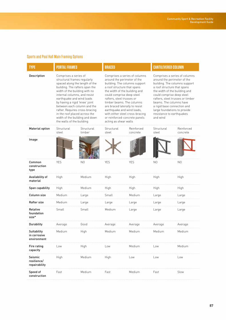
87
Community Sport & Recreation Facility Development Guide
Sports and Pool Hall Main Framing Options
TYPE PORTAL FRAMES BRACED CANTILEVERED COLUMN
Description Comprises a series of structural frames regularly spaced along the length of the building. The rafters span the width of the building with no internal columns, and resist earthquake and wind loads by having a rigid ‘knee’ joint between each column and the rafter. Requires cross-bracing in the roof placed across the width of the building and down the walls of the building
Comprises a series of columns around the perimeter of the building. The columns support a roof structure that spans the width of the building and could comprise deep steel rafters, steel trusses or timber beams. The columns are braced laterally to resist earthquake and wind loads, with either steel cross-bracing or reinforced-concrete panels acting as shear walls
Comprises a series of columns around the perimeter of the building. The columns support a roof structure that spans the width of the building and could comprise deep steel rafters, steel trusses or timber beams. The columns have a rigid base connection and large foundations to provide resistance to earthquakes and wind
Material option Structural steel
Structural timber
Structural steel
Reinforced concrete
Structural steel
Reinforced concrete
Image
Common construction type
YES NO YES YES NO NO
Availability of material
High Medium High High High High
Span capability High Medium High High High High
Column size Medium Large Small Medium Large Large
Rafter size Medium Large Large Large Large Large
Relative foundation size*
Small Small Medium Large Large Large
Durability Average Good Average Average Average Average
Suitability in corrosive environment
Medium High Medium Medium Medium Medium
Fire rating capacity
Low High Low Medium Low Medium
Seismic resilience/ repairability
High Medium High Low Low Low
Speed of construction
Fast Medium Fast Medium Fast Slow
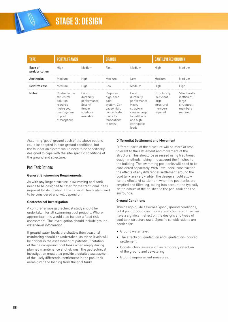
88
STAGE 3: DESIGN
TYPE PORTAL FRAMES BRACED CANTILEVERED COLUMN
Ease of prefabrication
High Medium Fast Medium High Medium
Aesthetics Medium High Medium Low Medium Medium
Relative cost Medium High Low Medium High High
Notes Cost-effective structural solution, requires high-spec paint system in pool atmosphere
Good durability performance. Several timber solutions available
Requires high-spec paint system. Can cause high, concentrated loads for foundations to resist
Good durability performance. Heavy structure causes large foundations and high earthquake loads
Structurally inefficient, large structural members required
Structurally inefficient, large structural members required
Assuming ‘good’ ground each of the above options could be adopted in poor ground conditions, but the foundation system would need to be specifically designed to cope with the site-specific conditions of the ground and structure.
Pool Tank Options
General Engineering Requirements
As with any large structure, a swimming pool tank needs to be designed to cater for the traditional loads imposed for its location. Other specific loads also need to be considered and will depend on:
Geotechnical Investigation
A comprehensive geotechnical study should be undertaken for all swimming pool projects. Where appropriate, this would also include a flood risk assessment. The investigation should include ground-water-level information.
If ground water levels are shallow then seasonal monitoring should be undertaken, as these levels will be critical in the assessment of potential floatation of the below-ground pool tanks when empty during planned maintenance shut-downs. The geotechnical investigation must also provide a detailed assessment of the likely differential settlement in the pool tank areas given the loading from the pool tanks.
Differential Settlement and Movement
Different parts of the structure will be more or less tolerant to the settlement and movement of the structure. This should be assessed using traditional design methods, taking into account the finishes to the building. The swimming pool tanks will need to be considered separately. With ‘level deck’ construction the effects of any differential settlement around the pool tank are very visible. The design should allow for the effects of settlement when the pool tanks are emptied and filled, eg, taking into account the typically brittle nature of the finishes to the pool tank and the surrounds.
Ground Conditions
This design guide assumes ‘good’, ground conditions, but if poor ground conditions are encountered they can have a significant effect on the designs and types of pool tank structure used. Specific considerations are needed for:
• Ground water level
• The effects of liquefaction and liquefaction-induced settlement
• Construction issues such as temporary retention of the ground and dewatering
• Ground improvement measures.
89
Community Sport & Recreation Facility Development Guide
Construction
Normal building tolerances will apply to the building generally, except where special finishes might be required, but special tolerances will apply to the pool tanks. If a pool tank is to be constructed as a competition pool, rather than as a community pool, more stringent tolerances would apply to the length of the tank and the flatness and verticality of the end walls. The level of competition should therefore be agreed with the client.
Once the level of tolerance has been determined, it is important for the design team to determine how this tolerance will be achieved. The final accuracy can be obtained using rendered finishes and the tiling, but to determine the size of the pool tank structure it is necessary to establish the type of finish early in the design process.
It is important to have a high level of on-site quality assurance, to ensure not only that tight tolerances are met but also that under-slab pipework is correctly installed and watertightness measures are adequately constructed. The design consultants may require a higher level of construction monitoring than is normally required for ‘normal’ buildings.
Structural Engineering Considerations
Foundations
The construction of foundations should allow for routing of underground services, especially filtration and drainage pipework.
The foundation solution needs to take into account the settlement requirements for the building frame and the additional, more onerous, requirements for any level deck channels. The foundation solutions for the two parts of the building may well be different based on the ground characteristics of the site. For example, the frame of the building might require a different foundation system from that of the pool tank to account for their different settlement requirements.
Pool Tanks, Balance Tanks and Plant Rooms
As well as below-ground pool tanks, balance tanks and plant rooms may need to be constructed below ground level.
Elements that will need special consideration and coordination include:
• A well designed and detailed concrete tank, which would typically be designed for a life of 50 years. Some options, in particular the use of proprietary stainless-steel tanks, may have lifespans that are significantly shorter
• Filtration-associated works for the location and size of balance tanks, channels etc
• The arrangements for access to the pool so that the locations of steps, platform lifts, ladders, rest ledges etc can be incorporated into the pool tank design
• Details of any movable floors and/or booms (if any), which need to be understood at the very early stages of design
• The use of the pool and level of any competition requirement, which will need to be established at the early stages of design to enable the plan tolerances of the construction to be confirmed. High-impact water sports, such as canoe polo, can cause damage to the pool and finishes, which may have an influence on the type of pool structure and finish adopted
• The location and installation requirements of lane ropes (and their storage) and timing pads, as well as any fixings required for nets, goals, dive boards and the like required for multi-use aquatic facilities
• The falls to the pool surround slabs
• Other requirements that could affect the structure of the tank, including temporary starting blocks, underwater speakers, underwater lighting, underwater cameras, pool covers etc.
90
STAGE 3: DESIGN
Design of Swimming Pool Tanks
Design
The design of the water-retaining elements must take into account conventional loadings applied to the structural elements and construction loads. Pool tanks need to be designed to be water retaining in accordance with specific design standards, and there are many specific loads that may need to be considered when designing to these requirements, such as:
• Earth pressure against tank wall and base
• Self-weight of the pool and supported structure
• Pool deck weight and associated live loads
• Seismic-induced loads on pool walls
• Frost heave pressure against pool slab (if in cold conditions)
• Liquefaction-induced loads and settlements (if in liquefaction-prone soil)
• Water pressures against tank wall and pool slab (if ground water level is high).
Pool surround slabs should be designed as water-retaining suspended slabs.
Joints
The pool tanks and surrounds could have joints in the structural elements. These joints need to be carefully considered and detailed so that they maintain their watertight properties and the joints align with the aesthetic requirements of any finishes.
Pool Tank Testing
Testing the pool tank is critically important, and an approved method of testing is set out in the relevant design standards. This method of testing should be followed precisely and the consequences of a failure of this test on the construction programme must be discussed with the main contractor. This may influence decisions made about the choice of sub-contractor and the proposed method of working.
Pool Tank Options
The selection of a pool tank system must be considered in the context of the local site and ground conditions, the topography, the availability of experienced concrete pool contractors and future flexibility drivers, and then against the needs analysis and the facility’s investment objectives.
The table below describes the two main options for commercial pool tank construction available in New Zealand.
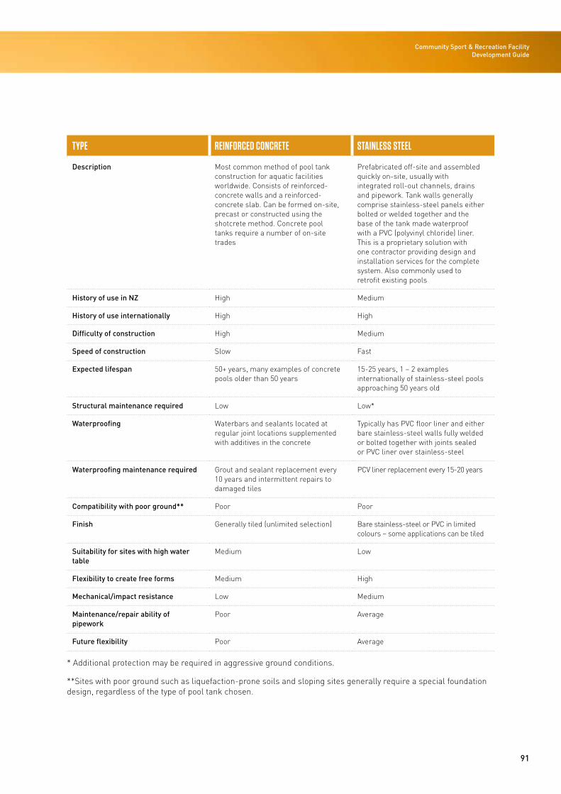
91
Community Sport & Recreation Facility Development Guide
TYPE REINFORCED CONCRETE STAINLESS STEEL
Description Most common method of pool tank construction for aquatic facilities worldwide. Consists of reinforced-concrete walls and a reinforced-concrete slab. Can be formed on-site, precast or constructed using the shotcrete method. Concrete pool tanks require a number of on-site trades
Prefabricated off-site and assembled quickly on-site, usually with integrated roll-out channels, drains and pipework. Tank walls generally comprise stainless-steel panels either bolted or welded together and the base of the tank made waterproof with a PVC (polyvinyl chloride) liner. This is a proprietary solution with one contractor providing design and installation services for the complete system. Also commonly used to retrofit existing pools
History of use in NZ High Medium
History of use internationally High High
Difficulty of construction High Medium
Speed of construction Slow Fast
Expected lifespan 50+ years, many examples of concrete pools older than 50 years
15-25 years, 1 – 2 examples internationally of stainless-steel pools approaching 50 years old
Structural maintenance required Low Low*
Waterproofing Waterbars and sealants located at regular joint locations supplemented with additives in the concrete
Typically has PVC floor liner and either bare stainless-steel walls fully welded or bolted together with joints sealed or PVC liner over stainless-steel
Waterproofing maintenance required Grout and sealant replacement every 10 years and intermittent repairs to damaged tiles
PCV liner replacement every 15-20 years
Compatibility with poor ground** Poor Poor
Finish Generally tiled (unlimited selection) Bare stainless-steel or PVC in limited colours – some applications can be tiled
Suitability for sites with high water table
Medium Low
Flexibility to create free forms Medium High
Mechanical/impact resistance Low Medium
Maintenance/repair ability of pipework
Poor Average
Future flexibility Poor Average
* Additional protection may be required in aggressive ground conditions.
**Sites with poor ground such as liquefaction-prone soils and sloping sites generally require a special foundation design, regardless of the type of pool tank chosen.
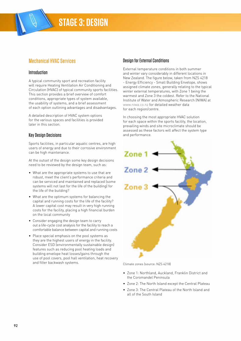
92
STAGE 3: DESIGN
Mechanical HVAC Services
Introduction
A typical community sport and recreation facility will require Heating Ventilation Air Conditioning and Circulation (HVAC) of typical community sports facilities. This section provides a brief overview of comfort conditions, appropriate types of system available, the usability of systems, and a brief assessment of each option outlining advantages and disadvantages.
A detailed description of HVAC system options for the various spaces and facilities is provided later in this section.
Key Design Decisions
Sports facilities, in particular aquatic centres, are high users of energy and due to their corrosive environment can be high maintenance.
At the outset of the design some key design decisions need to be reviewed by the design team, such as:
• What are the appropriate systems to use that are robust, meet the client’s performance criteria and can be serviced and maintained and replaced (some systems will not last for the life of the building) for the life of the building?
• What are the optimum systems for balancing the capital and running costs for the life of the facility? A lower capital cost may result in very high running costs for the facility, placing a high financial burden on the local community
• Consider engaging the design team to carry out a life-cycle cost analysis for the facility to reach a comfortable balance between capital and running costs
• Place special emphasis on the pool systems as they are the highest users of energy in the facility. Consider ESD (environmentally sustainable design) features such as reducing pool heating loads and building envelope heat losses/gains through the use of pool covers, pool hall ventilation, heat recovery and filter backwash systems.
Design for External Conditions
External temperature conditions in both summer and winter vary considerably in different locations in New Zealand. The figure below, taken from NZS 4218 - Energy Efficiency - Small Building Envelope, shows assigned climate zones, generally relating to the typical winter external temperatures, with Zone 1 being the warmest and Zone 3 the coldest. Refer to the National Institute of Water and Atmospheric Research (NIWA) at www.niwa.co.nz for detailed weather data for each region/centre.
In choosing the most appropriate HVAC solution for each space within the sports facility, the location, prevailing winds and site microclimate should be assessed as these factors will affect the system type and performance.
Climate zones (source: NZS 4218)
• Zone 1: Northland, Auckland, Franklin District and the Coromandel Peninsula
• Zone 2: The North Island except the Central Plateau
• Zone 3: The Central Plateau of the North Island and all of the South Island
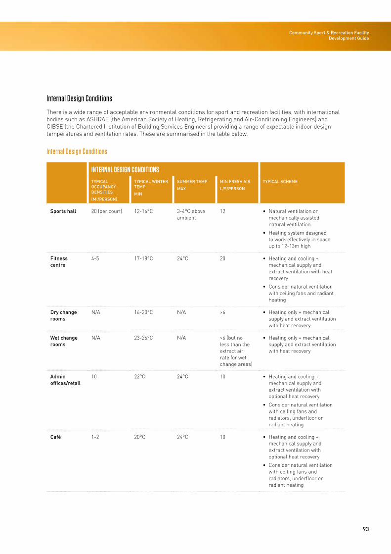
93
Community Sport & Recreation Facility Development Guide
Internal Design Conditions
There is a wide range of acceptable environmental conditions for sport and recreation facilities, with international bodies such as ASHRAE (the American Society of Heating, Refrigerating and Air-Conditioning Engineers) and CIBSE (the Chartered Institution of Building Services Engineers) providing a range of expectable indoor design temperatures and ventilation rates. These are summarised in the table below.
Internal Design Conditions
INTERNAL DESIGN CONDITIONSTYPICAL OCCUPANCY DENSITIES
(M2/PERSON)
TYPICAL WINTER TEMP
MIN
SUMMER TEMP
MAX
MIN FRESH AIR
L/S/PERSON
TYPICAL SCHEME
Sports hall 20 (per court) 12-16°C 3-4°C above ambient
12 • Natural ventilation or mechanically assisted natural ventilation
• Heating system designed to work effectively in space up to 12-13m high
Fitness centre
4-5 17-18°C 24°C 20 • Heating and cooling + mechanical supply and extract ventilation with heat recovery
• Consider natural ventilation with ceiling fans and radiant heating
Dry change rooms
N/A 16-20°C N/A >6 • Heating only + mechanical supply and extract ventilation with heat recovery
Wet change rooms
N/A 23-26°C N/A >6 (but no less than the extract air rate for wet change areas)
• Heating only + mechanical supply and extract ventilation with heat recovery
Admin offices/retail
10 22°C 24°C 10 • Heating and cooling + mechanical supply and extract ventilation with optional heat recovery
• Consider natural ventilation with ceiling fans and radiators, underfloor or radiant heating
Café 1-2 20°C 24°C 10 • Heating and cooling + mechanical supply and extract ventilation with optional heat recovery
• Consider natural ventilation with ceiling fans and radiators, underfloor or radiant heating
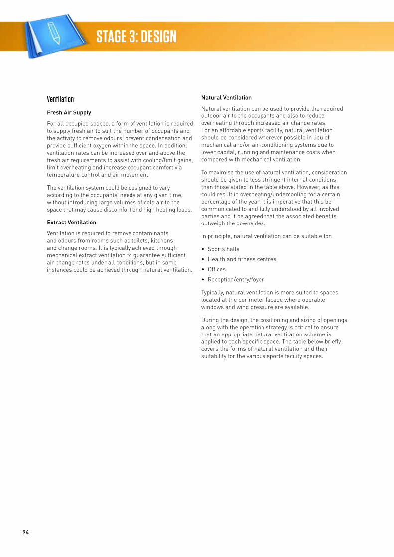
94
STAGE 3: DESIGN
Ventilation
Fresh Air Supply
For all occupied spaces, a form of ventilation is required to supply fresh air to suit the number of occupants and the activity to remove odours, prevent condensation and provide sufficient oxygen within the space. In addition, ventilation rates can be increased over and above the fresh air requirements to assist with cooling/limit gains, limit overheating and increase occupant comfort via temperature control and air movement.
The ventilation system could be designed to vary according to the occupants’ needs at any given time, without introducing large volumes of cold air to the space that may cause discomfort and high heating loads.
Extract Ventilation
Ventilation is required to remove contaminants and odours from rooms such as toilets, kitchens and change rooms. It is typically achieved through mechanical extract ventilation to guarantee sufficient air change rates under all conditions, but in some instances could be achieved through natural ventilation.
Natural Ventilation
Natural ventilation can be used to provide the required outdoor air to the occupants and also to reduce overheating through increased air change rates. For an affordable sports facility, natural ventilation should be considered wherever possible in lieu of mechanical and/or air-conditioning systems due to lower capital, running and maintenance costs when compared with mechanical ventilation.
To maximise the use of natural ventilation, consideration should be given to less stringent internal conditions than those stated in the table above. However, as this could result in overheating/undercooling for a certain percentage of the year, it is imperative that this be communicated to and fully understood by all involved parties and it be agreed that the associated benefits outweigh the downsides.
In principle, natural ventilation can be suitable for:
• Sports halls
• Health and fitness centres
• Offices
• Reception/entry/foyer.
Typically, natural ventilation is more suited to spaces located at the perimeter façade where operable windows and wind pressure are available.
During the design, the positioning and sizing of openings along with the operation strategy is critical to ensure that an appropriate natural ventilation scheme is applied to each specific space. The table below briefly covers the forms of natural ventilation and their suitability for the various sports facility spaces.
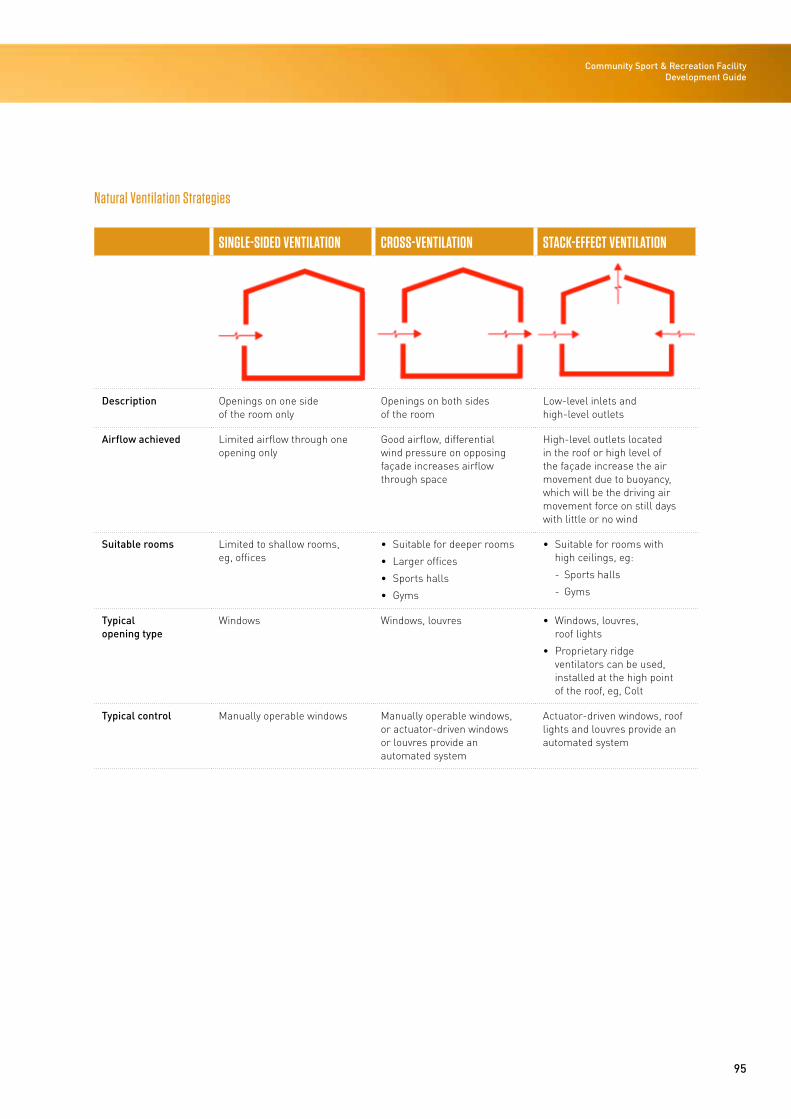
95
Community Sport & Recreation Facility Development Guide
Natural Ventilation Strategies
SINGLE-SIDED VENTILATION CROSS-VENTILATION STACK-EFFECT VENTILATION
Description Openings on one side of the room only
Openings on both sides of the room
Low-level inlets and high-level outlets
Airflow achieved Limited airflow through one opening only
Good airflow, differential wind pressure on opposing façade increases airflow through space
High-level outlets located in the roof or high level of the façade increase the air movement due to buoyancy, which will be the driving air movement force on still days with little or no wind
Suitable rooms Limited to shallow rooms, eg, offices
• Suitable for deeper rooms
• Larger offices
• Sports halls
• Gyms
• Suitable for rooms with high ceilings, eg:
- Sports halls
- Gyms
Typical opening type
Windows Windows, louvres • Windows, louvres, roof lights
• Proprietary ridge ventilators can be used, installed at the high point of the roof, eg, Colt
Typical control Manually operable windows Manually operable windows, or actuator-driven windows or louvres provide an automated system
Actuator-driven windows, roof lights and louvres provide an automated system
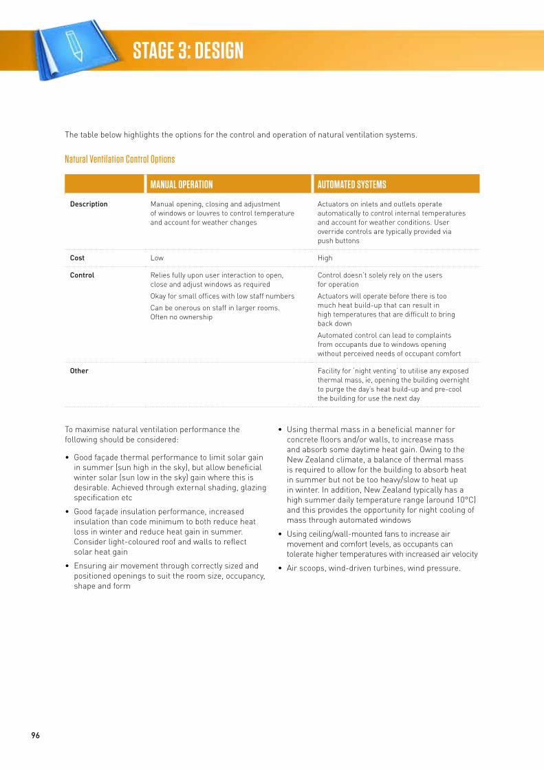
96
STAGE 3: DESIGN
The table below highlights the options for the control and operation of natural ventilation systems.
Natural Ventilation Control Options
MANUAL OPERATION AUTOMATED SYSTEMS
Description Manual opening, closing and adjustment of windows or louvres to control temperature and account for weather changes
Actuators on inlets and outlets operate automatically to control internal temperatures and account for weather conditions. User override controls are typically provided via push buttons
Cost Low High
Control Relies fully upon user interaction to open, close and adjust windows as required
Okay for small offices with low staff numbers
Can be onerous on staff in larger rooms. Often no ownership
Control doesn’t solely rely on the users for operation
Actuators will operate before there is too much heat build-up that can result in high temperatures that are difficult to bring back down
Automated control can lead to complaints from occupants due to windows opening without perceived needs of occupant comfort
Other Facility for ‘night venting’ to utilise any exposed thermal mass, ie, opening the building overnight to purge the day’s heat build-up and pre-cool the building for use the next day
To maximise natural ventilation performance the following should be considered:
• Good façade thermal performance to limit solar gain in summer (sun high in the sky), but allow beneficial winter solar (sun low in the sky) gain where this is desirable. Achieved through external shading, glazing specification etc
• Good façade insulation performance, increased insulation than code minimum to both reduce heat loss in winter and reduce heat gain in summer. Consider light-coloured roof and walls to reflect solar heat gain
• Ensuring air movement through correctly sized and positioned openings to suit the room size, occupancy, shape and form
• Using thermal mass in a beneficial manner for concrete floors and/or walls, to increase mass and absorb some daytime heat gain. Owing to the New Zealand climate, a balance of thermal mass is required to allow for the building to absorb heat in summer but not be too heavy/slow to heat up in winter. In addition, New Zealand typically has a high summer daily temperature range (around 10°C) and this provides the opportunity for night cooling of mass through automated windows
• Using ceiling/wall-mounted fans to increase air movement and comfort levels, as occupants can tolerate higher temperatures with increased air velocity
• Air scoops, wind-driven turbines, wind pressure.
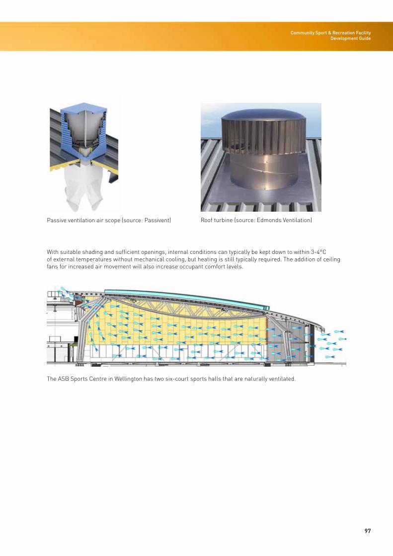
97
Community Sport & Recreation Facility Development Guide
Passive ventilation air scope (source: Passivent) Roof turbine (source: Edmonds Ventilation)
With suitable shading and sufficient openings, internal conditions can typically be kept down to within 3-4°C of external temperatures without mechanical cooling, but heating is still typically required. The addition of ceiling fans for increased air movement will also increase occupant comfort levels.
The ASB Sports Centre in Wellington has two six-court sports halls that are naturally ventilated.
98
STAGE 3: DESIGN
Potential issues for consideration:
• Security of open windows
• Draught and wind issues causing discomfort
• Manual operation requires user interaction, automated operation can be costly
• External noise issues affecting users
• Noise emanating from the sports hall to adjacent properties, sports hall whistles etc
• Ventilation rates are not guaranteed as the external conditions affect performance.
Mechanically Assisted Natural Ventilation
Consideration should be given to mechanically assisted natural ventilation where there is limited scope for openings in the façade or no opportunity for high-level openings.
The addition of a high-level mechanical extract system promotes airflow on still days when limited air movement occurs in a natural ventilated system. This can be useful where ceilings are lower and there is limited scope for warmer air to rise and stratify at a high level above the occupants.
Full Mechanical Ventilation
In some instances natural ventilation will not be an appropriate solution and a full mechanical ventilation system will be required. Typical drivers are likely to be:
• Privacy required or external noise nuisance not acceptable – opening windows not acceptable
• Rooms located internally – no scope for openable windows
• High density of people cannot be cooled or ventilated adequately by natural ventilation.
Heating and Cooling
Heating and cooling should be provided to achieve the internal design conditions as outlined earlier in this section, while accounting for the specific building form and site location. Refer to the HVAC options for individual spaces and the pros and cons of each system as outlined in this section.
Primary Energy/Fuel Source
During the concept phase, local utilities should be contacted and the available fuel source options determined; this will then dictate the HVAC options considered.
Typical fuel source options are listed in the table below.
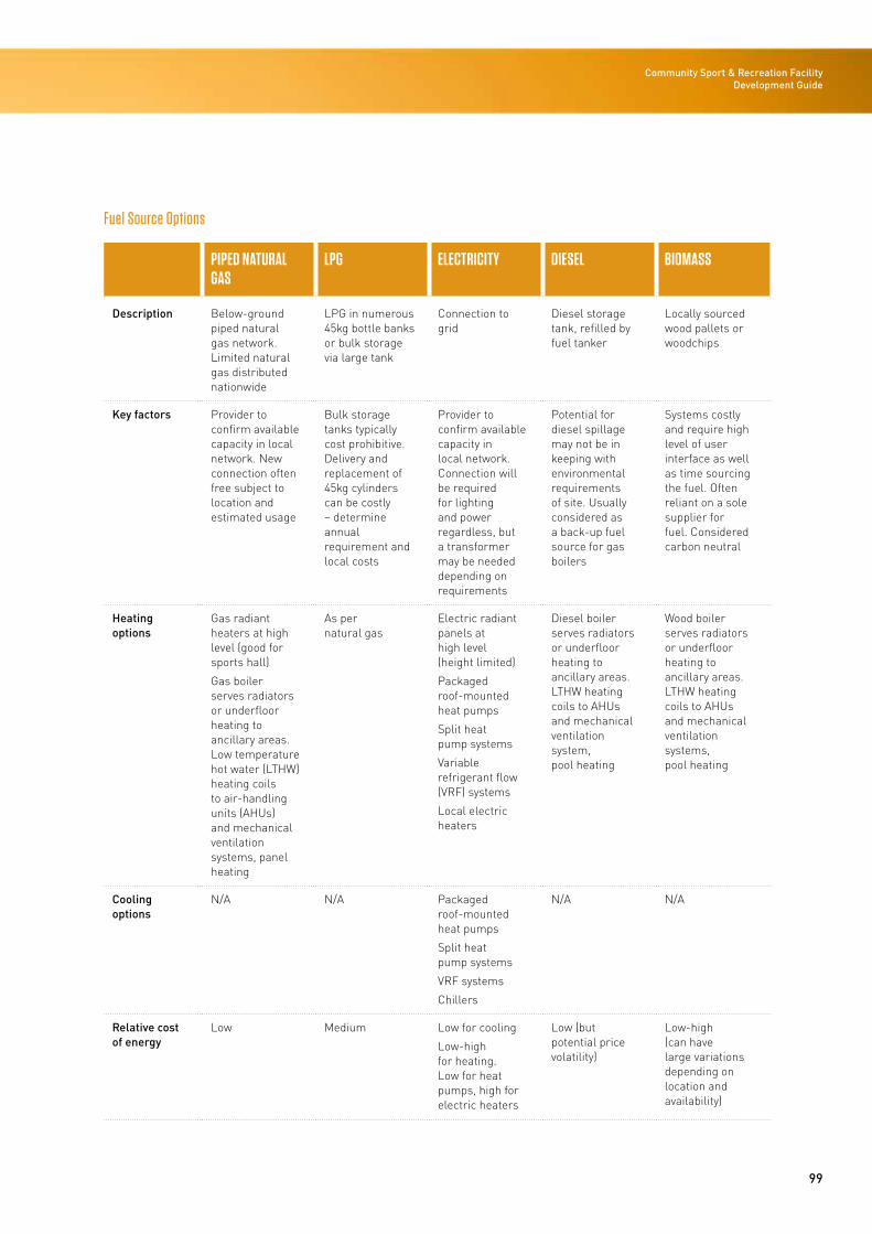
99
Community Sport & Recreation Facility Development Guide
Fuel Source Options
PIPED NATURAL GAS
LPG ELECTRICITY DIESEL BIOMASS
Description Below-ground piped natural gas network. Limited natural gas distributed nationwide
LPG in numerous 45kg bottle banks or bulk storage via large tank
Connection to grid
Diesel storage tank, refilled by fuel tanker
Locally sourced wood pallets or woodchips
Key factors Provider to confirm available capacity in local network. New connection often free subject to location and estimated usage
Bulk storage tanks typically cost prohibitive. Delivery and replacement of 45kg cylinders can be costly – determine annual requirement and local costs
Provider to confirm available capacity in local network. Connection will be required for lighting and power regardless, but a transformer may be needed depending on requirements
Potential for diesel spillage may not be in keeping with environmental requirements of site. Usually considered as a back-up fuel source for gas boilers
Systems costly and require high level of user interface as well as time sourcing the fuel. Often reliant on a sole supplier for fuel. Considered carbon neutral
Heating options
Gas radiant heaters at high level (good for sports hall)
Gas boiler serves radiators or underfloor heating to ancillary areas. Low temperature hot water (LTHW) heating coils to air-handling units (AHUs) and mechanical ventilation systems, panel heating
As per natural gas
Electric radiant panels at high level (height limited)
Packaged roof-mounted heat pumps
Split heat pump systems
Variable refrigerant flow (VRF) systems
Local electric heaters
Diesel boiler serves radiators or underfloor heating to ancillary areas. LTHW heating coils to AHUs and mechanical ventilation system, pool heating
Wood boiler serves radiators or underfloor heating to ancillary areas. LTHW heating coils to AHUs and mechanical ventilation systems, pool heating
Cooling options
N/A N/A Packaged roof-mounted heat pumps
Split heat pump systems
VRF systems
Chillers
N/A N/A
Relative cost of energy
Low Medium Low for cooling
Low-high for heating. Low for heat pumps, high for electric heaters
Low (but potential price volatility)
Low-high (can have large variations depending on location and availability)
100
STAGE 3: DESIGN
HVAC Options for Individual Spaces
Sports Hall
Design Considerations
Community sports halls are typically large-volume spaces with high ceilings/roofs and multiple external walls. They are used for a variety of activities at different times throughout the year.
Ventilation is required to remove the players’ body heat and odours, supply fresh air, keep spectators cool (where applicable), maintain comfortable summertime conditions and prevent condensation. The ventilation system should be designed for controlled ventilation rates that can vary according to the occupants’ needs at any given time, without introducing large volumes of cold air into the space that may cause discomfort and high heating loads.
As the internal temperature range for a sports hall is broad, with sufficient ventilation, strict control of internal temperatures should not be required. For some activities and/or in certain periods of the year heating will be required to maintain comfort conditions but, subject to the location and the building design, this could be for minimal periods only, in which case heating could potentially be viewed as a ‘nice to have’.
As there is potential for the space to be used for sports such as badminton, a draught-free playing area should be considered with velocities less than 0.1m/s, which favours a well designed natural ventilation system.
HVAC Options
Gas-fired radiant overhead heaters are the preferred heating solution where piped natural gas is available. The heaters react quickly, heat surfaces rather than air (a similar heating method to the sun) so are ideal for large-volume spaces, are located at a high level to avoid court interference, and can be directional or zone-specific so they can serve side line spectators rather than the whole space if desired.
Such systems can be future-proofed by installing gas pipework, with the aim of installing the heaters at a later date should heating be required. Where retractable basketball rings form part of the sports hall, care should be taken in the positioning of the heaters.
Electric radiant heaters are an alternative, although running costs will be significantly higher (refer to the table below for heating comparisons).
Underfloor heating is not considered suitable for this type of space. However, given this does not integrate well with a sprung floor, the system is slow to react and the space heating requirements are likely to be intermittent.
Mechanically assisted natural ventilation, or full mechanical ventilation, with high-level extract fans should be also considered as an alternative as this can reduce the number of façade openings.
Air-conditioning with exposed ductwork, jet diffusers and fabric ductwork is an alternative where good temperature control is required. However, this is costly and more appropriate to a high-level or international sports facility with large volumes of spectator seating and tight temperature-control requirements.
With any option it is important to utilise solar shading and the thermal mass of the building to help keep the building at a comfortable temperature and control operational energy costs.
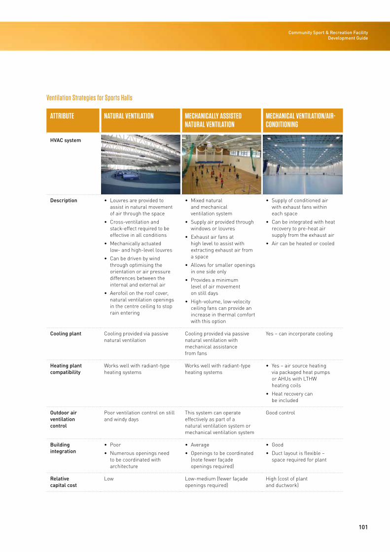
101
Community Sport & Recreation Facility Development Guide
Ventilation Strategies for Sports Halls
ATTRIBUTE NATURAL VENTILATION MECHANICALLY ASSISTED NATURAL VENTILATION
MECHANICAL VENTILATION/AIR-CONDITIONING
HVAC system
Description • Louvres are provided to assist in natural movement of air through the space
• Cross-ventilation and stack-effect required to be effective in all conditions
• Mechanically actuated low- and high-level louvres
• Can be driven by wind through optimising the orientation or air pressure differences between the internal and external air
• Aerofoil on the roof cover, natural ventilation openings in the centre ceiling to stop rain entering
• Mixed natural and mechanical ventilation system
• Supply air provided through windows or louvres
• Exhaust air fans at high level to assist with extracting exhaust air from a space
• Allows for smaller openings in one side only
• Provides a minimum level of air movement on still days
• High-volume, low-velocity ceiling fans can provide an increase in thermal comfort with this option
• Supply of conditioned air with exhaust fans within each space
• Can be integrated with heat recovery to pre-heat air supply from the exhaust air
• Air can be heated or cooled
Cooling plant Cooling provided via passive natural ventilation
Cooling provided via passive natural ventilation with mechanical assistance from fans
Yes – can incorporate cooling
Heating plant compatibility
Works well with radiant-type heating systems
Works well with radiant-type heating systems
• Yes – air source heating via packaged heat pumps or AHUs with LTHW heating coils
• Heat recovery can be included
Outdoor air ventilation control
Poor ventilation control on still and windy days
This system can operate effectively as part of a natural ventilation system or mechanical ventilation system
Good control
Building integration
• Poor
• Numerous openings need to be coordinated with architecture
• Average
• Openings to be coordinated (note fewer façade openings required)
• Good
• Duct layout is flexible – space required for plant
Relative capital cost
Low Low-medium (fewer façade openings required)
High (cost of plant and ductwork)
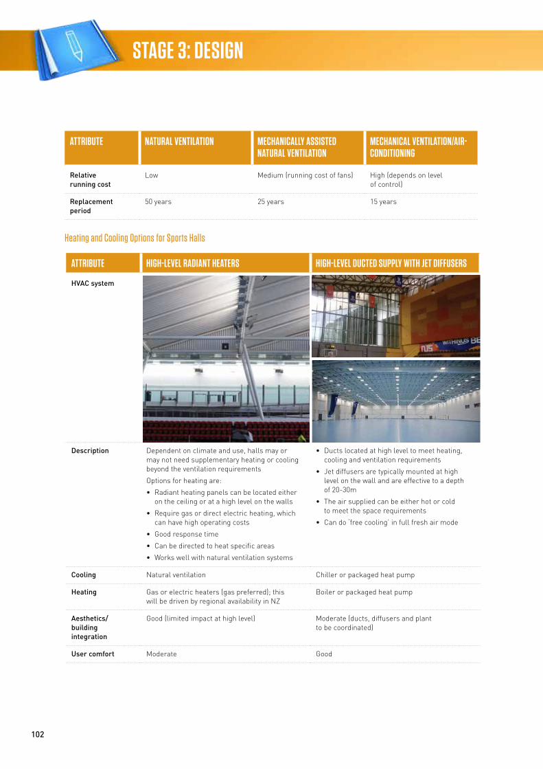
102
STAGE 3: DESIGN
ATTRIBUTE NATURAL VENTILATION MECHANICALLY ASSISTED NATURAL VENTILATION
MECHANICAL VENTILATION/AIR-CONDITIONING
Relative running cost
Low Medium (running cost of fans) High (depends on level of control)
Replacement period
50 years 25 years 15 years
Heating and Cooling Options for Sports Halls
ATTRIBUTE HIGH-LEVEL RADIANT HEATERS HIGH-LEVEL DUCTED SUPPLY WITH JET DIFFUSERS
HVAC system
Description Dependent on climate and use, halls may or may not need supplementary heating or cooling beyond the ventilation requirements
Options for heating are:
• Radiant heating panels can be located either on the ceiling or at a high level on the walls
• Require gas or direct electric heating, which can have high operating costs
• Good response time
• Can be directed to heat specific areas
• Works well with natural ventilation systems
• Ducts located at high level to meet heating, cooling and ventilation requirements
• Jet diffusers are typically mounted at high level on the wall and are effective to a depth of 20-30m
• The air supplied can be either hot or cold to meet the space requirements
• Can do ‘free cooling’ in full fresh air mode
Cooling Natural ventilation Chiller or packaged heat pump
Heating Gas or electric heaters (gas preferred); this will be driven by regional availability in NZ
Boiler or packaged heat pump
Aesthetics/ building integration
Good (limited impact at high level) Moderate (ducts, diffusers and plant to be coordinated)
User comfort Moderate Good
103
Community Sport & Recreation Facility Development Guide
ATTRIBUTE HIGH-LEVEL RADIANT HEATERS HIGH-LEVEL DUCTED SUPPLY WITH JET DIFFUSERS
Noise Low (care needed with gas-fired) Low
Relative capital cost
Medium (gas)
Low (electric)
High
Relative running cost
Medium (gas)
High (electric)
High (can be very high if not operated carefully – staff must be knowledgeable)
Estimated economic life
20 years 15-20 years
Fitness Centre
Design Considerations
Effective ventilation is usually the most critical factor because of the metabolic heat gains, body odour and humidity that can rapidly occur in such spaces. However, with fitness centres, gyms and studios the design set-points are often lower than those for sports halls and it is generally accepted that air-conditioning is required to meet the design conditions and the high level of activities.
Furthermore, these spaces can have a significantly higher occupancy density than sports halls and it is critical to meet the fresh air requirements of users who can range from a few people to many, and change in a very short period throughout the day.
Ventilation and thermal façade performance should be carefully considered to minimise the risk of condensation in these spaces specifically, given the low temperatures and high humidity levels associated with the activities within the space.
HVAC Options
For smaller facilities, multi-heat pump systems (such as VRF) or small modular heat pumps (such as domestic-style split direct expansion air-conditioning [DX] systems) are a cost-effective solution to provide local zone temperature control. Mechanical ventilation will be required to work in conjunction with these systems in order to provide fresh air and achieve sufficient air change rates. This could be achieved through common AHU-ducted systems through walls or roof fans or fresh air units complete with in-built heat recovery solutions.
For larger sports centres, typically either variable air volume (VAV) or fan coil units are used to provide the air-conditioning. Both these systems provide good air movement and close temperature control. Also, both these systems require central air-handling plant along with central heating and cooling plant, which may not be appropriate for smaller facilities. Another large-space solution for open-plan health and fitness centres is a constant air volume system. Options include packaged ducted heat pump units providing both heating and cooling and AHUs with heating and cooling coils served via a central plant. Air-side free cooling or an economiser operation helps to assist in reducing cooling energy consumption. Heat recovery, CO2 control and an economiser operation are all enhancements to these systems to conserve energy and reduce running costs and should be considered.
Natural ventilation or mechanically assisted natural ventilation complete with ceiling/wall-mounted fans could be considered as a cost-effective alternative to air-conditioning. Although internal temperature conditions will not always be maintained, user comfort could be increased through the increased air movement provided by ceiling- or wall-mounted fans. If natural ventilation is considered, site location and adjacent boundaries should be reviewed with respect to gym noise or music causing a nuisance to neighbours, particularly as these facilities operate extended hours and on weekends where council noise criteria become more onerous.
Where fitness rooms have distinct zones for cardio and weight training facilities, to reduce air-conditioning costs an alternative is spot cooling of cardio zones while allowing weight training areas to operate at higher temperatures that are more tolerated by the users.
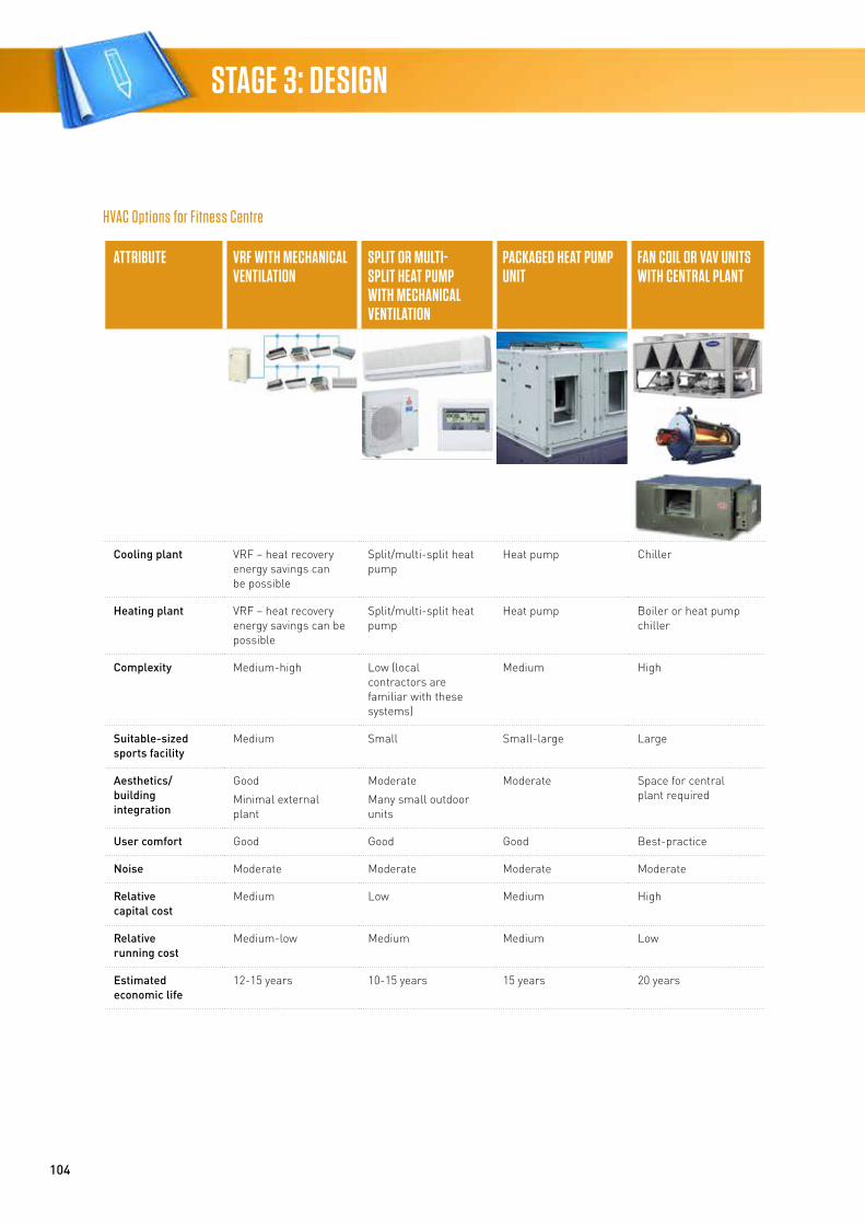
104
STAGE 3: DESIGN
HVAC Options for Fitness Centre
ATTRIBUTE VRF WITH MECHANICAL VENTILATION
SPLIT OR MULTI-SPLIT HEAT PUMP WITH MECHANICAL VENTILATION
PACKAGED HEAT PUMP UNIT
FAN COIL OR VAV UNITS WITH CENTRAL PLANT
Cooling plant VRF – heat recovery energy savings can be possible
Split/multi-split heat pump
Heat pump Chiller
Heating plant VRF – heat recovery energy savings can be possible
Split/multi-split heat pump
Heat pump Boiler or heat pump chiller
Complexity Medium-high Low (local contractors are familiar with these systems)
Medium High
Suitable-sized sports facility
Medium Small Small-large Large
Aesthetics/ building integration
Good
Minimal external plant
Moderate
Many small outdoor units
Moderate Space for central plant required
User comfort Good Good Good Best-practice
Noise Moderate Moderate Moderate Moderate
Relative capital cost
Medium Low Medium High
Relative running cost
Medium-low Medium Medium Low
Estimated economic life
12-15 years 10-15 years 15 years 20 years
105
Community Sport & Recreation Facility Development Guide
Change Areas and Toilets
Change rooms need to be mechanically or naturally ventilated to control odour and condensation issues. The change rooms need to be heated to provide thermal comfort to the users.
HVAC Options
The following ventilation options can be considered for the change room:
• Natural ventilation – this should be considered for smaller, low-occupancy, perimeter change rooms
• Mechanical ventilation – this system should ideally be designed to achieve 10-15 air changes per hour in the change room area. Ideally, the change rooms should be zoned so that supply air is provided to the change areas and exhausted from the toilet and shower facilities. Supply air will be mechanically tempered supply air either drawn directly to the space from outside or, where appropriate, drawn from the surrounding rooms.
Space heating, if desired, within the change rooms can be achieved with one of the following options:
• High-level radiant heaters provide a lower-cost option with a quick response time. This system would require gas or direct electric heating and would not be able to take advantage of the low-cost heating energy available from any central heating and cooling plant. It works well for smaller, naturally ventilated change rooms. Owing to the high ventilation rates within change rooms this is the preferred choice from an energy efficiency point of view.
Less preferred heating options due to high change room ventilation rates removing the heated air are:
• Local wall-mounted radiators with temperature regulating valves, which provide good comfort levels and local control to each room. A central boiler is required to provide a high-temperature heat source.
• Underfloor heating system – this may not have the lowest operating and maintenance costs but it can provide a high-quality environment, minimising moisture build-up on the floor. Underfloor heating can be costly, and heat output can be limited in areas with higher internal temperatures such as wet change areas.
Administration Areas/Offices/Retail Spaces
These spaces often require air-conditioning to meet the thermal requirements of each space, but with planning and locating these spaces on the perimeter, natural ventilation with perimeter heating should be considered. Outdoor air will be required to each space based on the occupancies, allowing for any intermittent usage factors.
HVAC Options
• VRF, split system and multi-split systems – cost-effective solutions that provide good individual control and can be specified with small-scale central control monitoring systems. Simultaneous heating and cooling can be provided across rooms with heat recovery. Fresh air is provided via heat recovery ventilation units forming part of the system. Local installers are often familiar with these systems and have the skill-set to install these systems
• Fan coil units – this is the traditional method of providing air-conditioning to an office space and can provide a good level of individual control in cellular spaces. Requires central heating and chilled water generation and pipework distribution; not cost-effective for small facilities
• Variable air volume system – this system works well in areas where occupancy levels can vary significantly and may be appropriate for waiting areas and meeting rooms. Requires central heating and chilled water generation and is normally cost-effective only in larger facilities
• Natural ventilation with perimeter heating through local radiators or underfloor heating – this should be considered for perimeter zones, with careful design of the building mass, shading and windows to ensure overheating is somewhat reduced
Reception, Foyer and Entry Areas
These spaces are transitory and as such temperature control of the whole space may not be required. This should be consulted on during the design stage to determine user and stakeholder requirements.
Natural ventilation with supplementary high-level ceiling/wall fans and radiant heating in occupied zones can work well in large-volume-type spaces.
106
STAGE 3: DESIGN
Reception staff should be provided with local heating, and options such as wind lobbies and/or door curtains assist with reducing discomfort due to draughts. Wind lobbies are preferred over door curtains due to the very high energy use of air curtains.
Entry areas are often designed with large areas of glazing, and in such cases care should be taken to both mitigate potential cold down-draughts in winter and reduce overheating in summer. The location of these in respect to the site and prevailing winds should be considered early in the design process (ie, master planning stage).
Where areas are enclosed or densely occupied for significant periods, air-conditioning is likely required.
Café Areas
The type of café can greatly influence the level of HVAC services. A ‘heat and eat’ type catering kitchen does not usually require a commercial kitchen extract hood, whereas kitchens with commercial cooking appliances such as deep fryers require commercial extract hoods and exhaust systems. This needs to be considered and agreed during the design by the users and stakeholders etc.
Seated café areas will require outdoor air and conditioning similar to the requirements of the administration and office areas. Where café seating forms part of a foyer, strategies as described above apply.
Dry Storage Areas
Mechanical extract ventilation.
Plant Areas
Natural ventilation via louvres in the façade to limit overheating. Provide high and low louvres in accordance with the gas standards where gas boilers are located in the plant room.
Pool Hall Ventilation and Heating
Pool heating in aquatic centres encompasses pool water heating and pool hall space heating. It is critical for bather comfort and health while being a major consumer of energy. Pool hall space temperature and humidity are always a compromise between bather comfort, spectator comfort, pool-side staff expectations, condensation control and energy use.
To ensure an efficient aquatic facility it is critical that the façade elements are selected for a high level of thermal performance, such as high R values, effective provisions to avoid thermal bridging and airtightness.
Pool Hall Temperature and Humidity
Pool hall indoor temperatures are typically around 1-3°C higher than the pool water temperature(s), with humidity in the 50-70 percent range. Typically, pool halls are not heated above 32°C due to occupant discomfort and the energy associated with maintaining the elevated hall temperature.
Lower pool hall humidity mitigates condensation control and increases occupant comfort. However, lower humidity means increases in pool water evaporation, pool heating demand, required air change rate to control humidity etc.
Ventilation Air Movement
The main aspects to be addressed by HVAC systems for the pool hall are:
• Aim for uniform space conditions in the occupied zone to promote bather comfort
• Minimise draughts in the occupied zone
• Reduce the level of disinfection by-products (DBPs) in the pool hall air for improved bather amenity
• Minimise condensation on the building fabric.
An awareness of the potential health effects associated with short- and long-term exposure to volatile DBPs is driving the current thinking of setting up the ventilation arrangement to assist in reducing the level of volatile DBPs in the bather zone. Some opportunities to improve the pool surface air quality are:
• Setting up the ventilation arrangement to assist in reducing the level of volatile DBPs in the bather zone
• Increasing the outside air intake for dilution and improved air quality.
Typically, pool hall ventilation systems have at least four to six air changes per hour to maintain appropriate humidity levels.
Pool halls should be maintained at a negative pressure with respect to the surrounding areas to minimise pool hall air migration to the dry areas of the facility. For the areas surrounding the pool halls, the respective HVAC systems shall be designed with a positive supply air ventilation system to minimise pool hall air ingress to these areas.
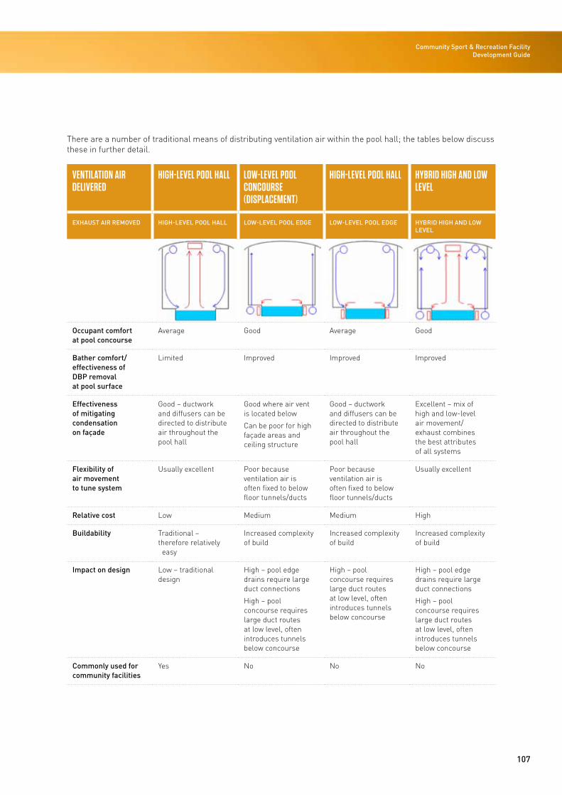
107
Community Sport & Recreation Facility Development Guide
There are a number of traditional means of distributing ventilation air within the pool hall; the tables below discuss these in further detail.
VENTILATION AIR DELIVERED
HIGH-LEVEL POOL HALL LOW-LEVEL POOL CONCOURSE (DISPLACEMENT)
HIGH-LEVEL POOL HALL HYBRID HIGH AND LOW LEVEL
EXHAUST AIR REMOVED HIGH-LEVEL POOL HALL LOW-LEVEL POOL EDGE LOW-LEVEL POOL EDGE HYBRID HIGH AND LOW LEVEL
Occupant comfort at pool concourse
Average Good Average Good
Bather comfort/ effectiveness of DBP removal at pool surface
Limited Improved Improved Improved
Effectiveness of mitigating condensation on façade
Good – ductwork and diffusers can be directed to distribute air throughout the pool hall
Good where air vent is located below
Can be poor for high façade areas and ceiling structure
Good – ductwork and diffusers can be directed to distribute air throughout the pool hall
Excellent – mix of high and low-level air movement/exhaust combines the best attributes of all systems
Flexibility of air movement to tune system
Usually excellent Poor because ventilation air is often fixed to below floor tunnels/ducts
Poor because ventilation air is often fixed to below floor tunnels/ducts
Usually excellent
Relative cost Low Medium Medium High
Buildability Traditional – therefore relatively easy
Increased complexity of build
Increased complexity of build
Increased complexity of build
Impact on design Low – traditional design
High – pool edge drains require large duct connections
High – pool concourse requires large duct routes at low level, often introduces tunnels below concourse
High – pool concourse requires large duct routes at low level, often introduces tunnels below concourse
High – pool edge drains require large duct connections
High – pool concourse requires large duct routes at low level, often introduces tunnels below concourse
Commonly used for community facilities
Yes No No No
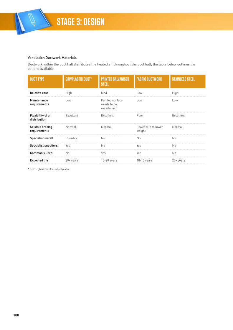
108
STAGE 3: DESIGN
Ventilation Ductwork Materials
Ductwork within the pool hall distributes the heated air throughout the pool hall; the table below outlines the options available.
DUCT TYPE GRP/PLASTIC DUCT* PAINTED GALVANISED STEEL
FABRIC DUCTWORK STAINLESS STEEL
Relative cost High Med Low High
Maintenance requirements
Low Painted surface needs to be maintained
Low Low
Flexibility of air distribution
Excellent Excellent Poor Excellent
Seismic bracing requirements
Normal Normal Lower due to lower weight
Normal
Specialist install Possibly No No No
Specialist suppliers Yes No Yes No
Commonly used No Yes Yes No
Expected life 20+ years 15-20 years 10-15 years 20+ years
* GRP – glass-reinforced polyester
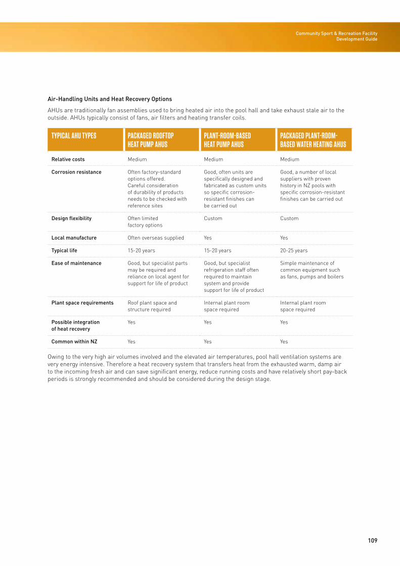
109
Community Sport & Recreation Facility Development Guide
Air-Handling Units and Heat Recovery Options
AHUs are traditionally fan assemblies used to bring heated air into the pool hall and take exhaust stale air to the outside. AHUs typically consist of fans, air filters and heating transfer coils.
TYPICAL AHU TYPES PACKAGED ROOFTOP HEAT PUMP AHUS
PLANT-ROOM-BASED HEAT PUMP AHUS
PACKAGED PLANT-ROOM-BASED WATER HEATING AHUS
Relative costs Medium Medium Medium
Corrosion resistance Often factory-standard options offered. Careful consideration of durability of products needs to be checked with reference sites
Good, often units are specifically designed and fabricated as custom units so specific corrosion-resistant finishes can be carried out
Good, a number of local suppliers with proven history in NZ pools with specific corrosion-resistant finishes can be carried out
Design flexibility Often limited factory options
Custom Custom
Local manufacture Often overseas supplied Yes Yes
Typical life 15-20 years 15-20 years 20-25 years
Ease of maintenance Good, but specialist parts may be required and reliance on local agent for support for life of product
Good, but specialist refrigeration staff often required to maintain system and provide support for life of product
Simple maintenance of common equipment such as fans, pumps and boilers
Plant space requirements Roof plant space and structure required
Internal plant room space required
Internal plant room space required
Possible integration of heat recovery
Yes Yes Yes
Common within NZ Yes Yes Yes
Owing to the very high air volumes involved and the elevated air temperatures, pool hall ventilation systems are very energy intensive. Therefore a heat recovery system that transfers heat from the exhausted warm, damp air to the incoming fresh air and can save significant energy, reduce running costs and have relatively short pay-back periods is strongly recommended and should be considered during the design stage.
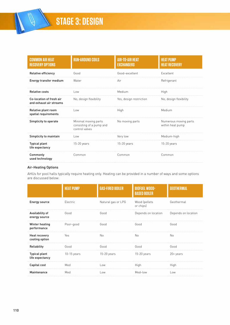
110
STAGE 3: DESIGN
COMMON AIR HEAT RECOVERY OPTIONS
RUN-AROUND COILS AIR-TO-AIR HEAT EXCHANGERS
HEAT PUMP HEAT RECOVERY
Relative efficiency Good Good–excellent Excellent
Energy transfer medium Water Air Refrigerant
Relative costs Low Medium High
Co-location of fresh air and exhaust air streams
No, design flexibility Yes, design restriction No, design flexibility
Relative plant room spatial requirements
Low High Medium
Simplicity to operate Minimal moving parts consisting of a pump and control valves
No moving parts Numerous moving parts within heat pump
Simplicity to maintain Low Very low Medium-high
Typical plant life expectancy
15-20 years 15-20 years 15-20 years
Commonly used technology
Common Common Common
Air-Heating Options
AHUs for pool halls typically require heating only. Heating can be provided in a number of ways and some options are discussed below:
HEAT PUMP GAS-FIRED BOILER BIOFUEL WOOD- BASED BOILER
GEOTHERMAL
Energy source Electric Natural gas or LPG Wood (pellets or chips)
Geothermal
Availability of energy source
Good Good Depends on location Depends on location
Winter heating performance
Poor–good Good Good Good
Heat recovery cooling option
Yes No No No
Reliability Good Good Good Good
Typical plant life expectancy
10-15 years 15-20 years 15-20 years 20+ years
Capital cost Med Low High High
Maintenance Med Low Med–low Low
111
Community Sport & Recreation Facility Development Guide
The use of pool covers is recommended for ventilation energy saving when the pools are not in use. The use of pool covers reduces the heating energy of the pool hall by reducing the amount of evaporation from the pool surface, which then
• Reduces the cooling effect to the pool hall air
• Reduces the humidity within the pool hall that, in turn, reduces the amount of ventilation air needed.
Control Systems
The types of control system used will depend on the size and type of building services installed and their complexity. The size and complexity of the facility will dictate the capital cost-effectiveness of either system.
Proprietary control systems can be provided with most building services systems, but often have limited compatibility or flexibility to interface with other control systems. Another disadvantage is for a holistic site-wide observation or monitoring of system performance or energy usage. A site-wide building management system (BMS) provides a means of replacing numerous proprietary control systems by consolidating controls onto one building-wide platform that can be used to observe performance from a single central location.
Hydraulic Design
Potable water used at sports facilities is typically separated into four main categories: make-up water for the swimming pools, the wet facility amenities, the indoor courts’ amenities and any site irrigation. The volume of water used in each of these categories will vary significantly depending on local climate, number of users, the type of pool filter system provided and the level of non-potable water used on-site.
Key Design Decisions
Combined sports and aquatic facilities use high volumes of domestic cold and hot water and discharge high volumes of waste water. Key design areas to focus on are:
• Utility potable water supply capacity within the street – initial pool filling usually dictates high water flow and pressure needed
• Utility sanitary waste water supply capacity to the street – pool filter backwash discharge flow rates are high whereas capacity at the street connection is lower
• Domestic hot water (DHW) generation – aquatic facilities have high shower use, whereas dry sports facilities rates can have intermittent shower use and a highly variable number of users.
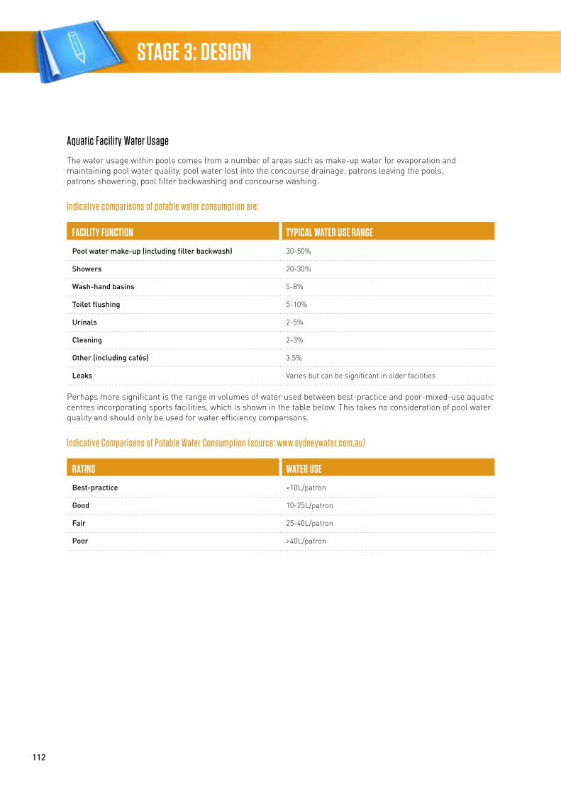
112
STAGE 3: DESIGN
Aquatic Facility Water Usage
The water usage within pools comes from a number of areas such as make-up water for evaporation and maintaining pool water quality, pool water lost into the concourse drainage, patrons leaving the pools, patrons showering, pool filter backwashing and concourse washing.
Indicative comparisons of potable water consumption are:
FACILITY FUNCTION TYPICAL WATER USE RANGE
Pool water make-up (including filter backwash) 30-50%
Showers 20-30%
Wash-hand basins 5-8%
Toilet flushing 5-10%
Urinals 2-5%
Cleaning 2-3%
Other (including cafés) 3.5%
Leaks Varies but can be significant in older facilities
Perhaps more significant is the range in volumes of water used between best-practice and poor-mixed-use aquatic centres incorporating sports facilities, which is shown in the table below. This takes no consideration of pool water quality and should only be used for water efficiency comparisons.
Indicative Comparisons of Potable Water Consumption (source: www.sydneywater.com.au)
RATING WATER USE
Best-practice <10L/patron
Good 10-25L/patron
Fair 25-40L/patron
Poor >40L/patron
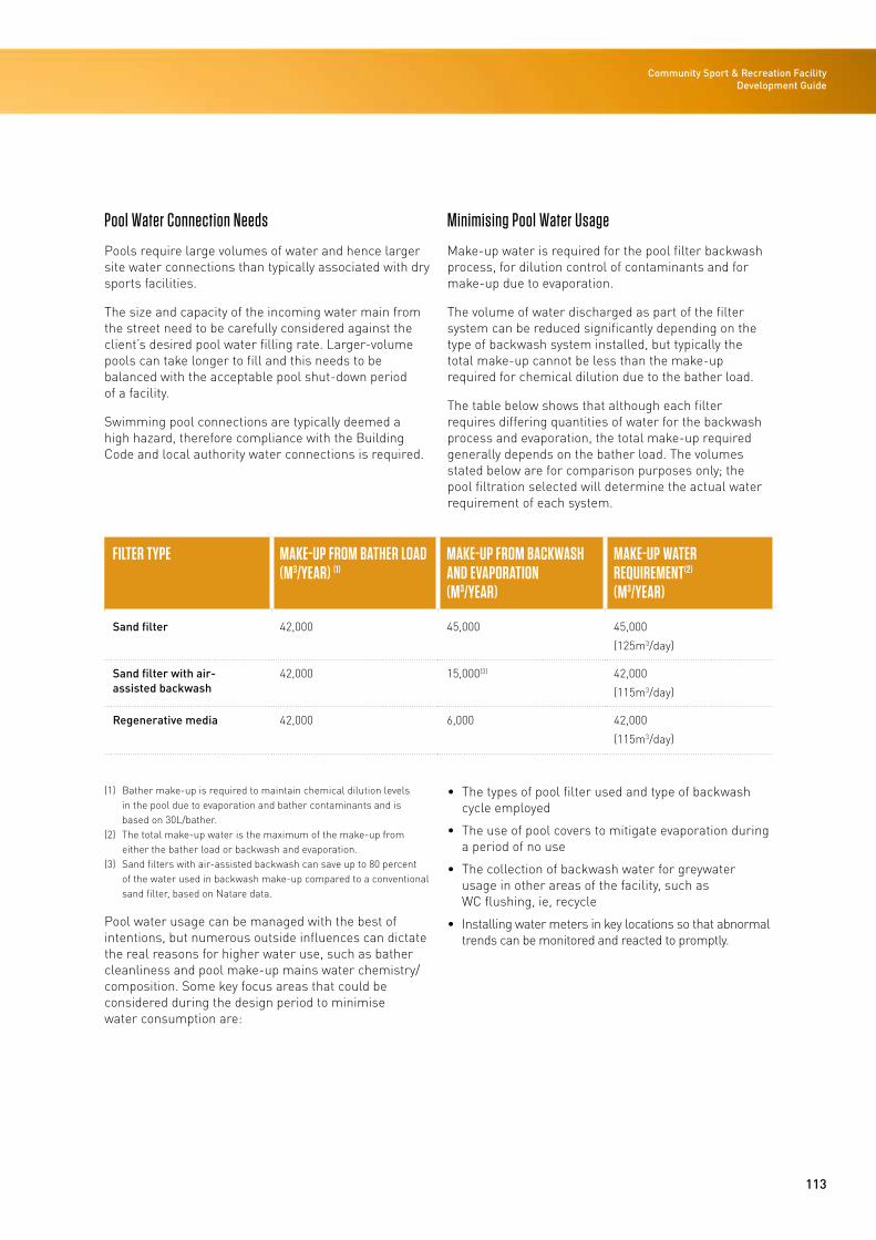
113
Community Sport & Recreation Facility Development Guide
Pool Water Connection Needs
Pools require large volumes of water and hence larger site water connections than typically associated with dry sports facilities.
The size and capacity of the incoming water main from the street need to be carefully considered against the client’s desired pool water filling rate. Larger-volume pools can take longer to fill and this needs to be balanced with the acceptable pool shut-down period of a facility.
Swimming pool connections are typically deemed a high hazard, therefore compliance with the Building Code and local authority water connections is required.
Minimising Pool Water Usage
Make-up water is required for the pool filter backwash process, for dilution control of contaminants and for make-up due to evaporation.
The volume of water discharged as part of the filter system can be reduced significantly depending on the type of backwash system installed, but typically the total make-up cannot be less than the make-up required for chemical dilution due to the bather load.
The table below shows that although each filter requires differing quantities of water for the backwash process and evaporation, the total make-up required generally depends on the bather load. The volumes stated below are for comparison purposes only; the pool filtration selected will determine the actual water requirement of each system.
FILTER TYPE MAKE-UP FROM BATHER LOAD(M3/YEAR) (1)
MAKE-UP FROM BACKWASH AND EVAPORATION(M3/YEAR)
MAKE-UP WATER REQUIREMENT(2)
(M3/YEAR)
Sand filter 42,000 45,000 45,000
(125m3/day)
Sand filter with air-assisted backwash
42,000 15,000(3) 42,000
(115m3/day)
Regenerative media 42,000 6,000 42,000
(115m3/day)
(1) Bather make-up is required to maintain chemical dilution levels in the pool due to evaporation and bather contaminants and is based on 30L/bather.
(2) The total make-up water is the maximum of the make-up from either the bather load or backwash and evaporation.
(3) Sand filters with air-assisted backwash can save up to 80 percent of the water used in backwash make-up compared to a conventional sand filter, based on Natare data.
Pool water usage can be managed with the best of intentions, but numerous outside influences can dictate the real reasons for higher water use, such as bather cleanliness and pool make-up mains water chemistry/composition. Some key focus areas that could be considered during the design period to minimise water consumption are:
• The types of pool filter used and type of backwash cycle employed
• The use of pool covers to mitigate evaporation during a period of no use
• The collection of backwash water for greywater usage in other areas of the facility, such as WC flushing, ie, recycle
• Installing water meters in key locations so that abnormal trends can be monitored and reacted to promptly.
114
STAGE 3: DESIGN
Indoor Courts’ and Wet Facilities’ Amenities
Possible areas to reduce water usage include:
• Reduce flow rates to the showers
• Have push buttons with adjustable timers on all showers
• Provide pool-side showers as this tends to reduce the amount of time patrons spend showering to just rinsing off rather than washing
• Installing water meters in key locations so that abnormal trends can be monitored and reacted to promptly.
Irrigation
Ways in which to reduce the water demand for irrigation include:
• Planting drought-tolerant plants that require no additional watering once established
• Implementing a water-efficient irrigation system comprising subsoil drip systems and automatic timers with rainwater or soil moisture sensors
• Installing water meters in key locations so that abnormal trends can be monitored and reacted to promptly.
Domestic Hot Water
The large consumers of DHW within such facilities are the shower amenities within the pool and dry sports areas.
Pool amenities typically have a higher patron usage of showers and more constant use, whereas dry sport amenities can have varying usage depending on the type of use, ie, local sports club night vs regional sports tournament.
DHW can be generated by numerous means and some typical examples are outlined below.
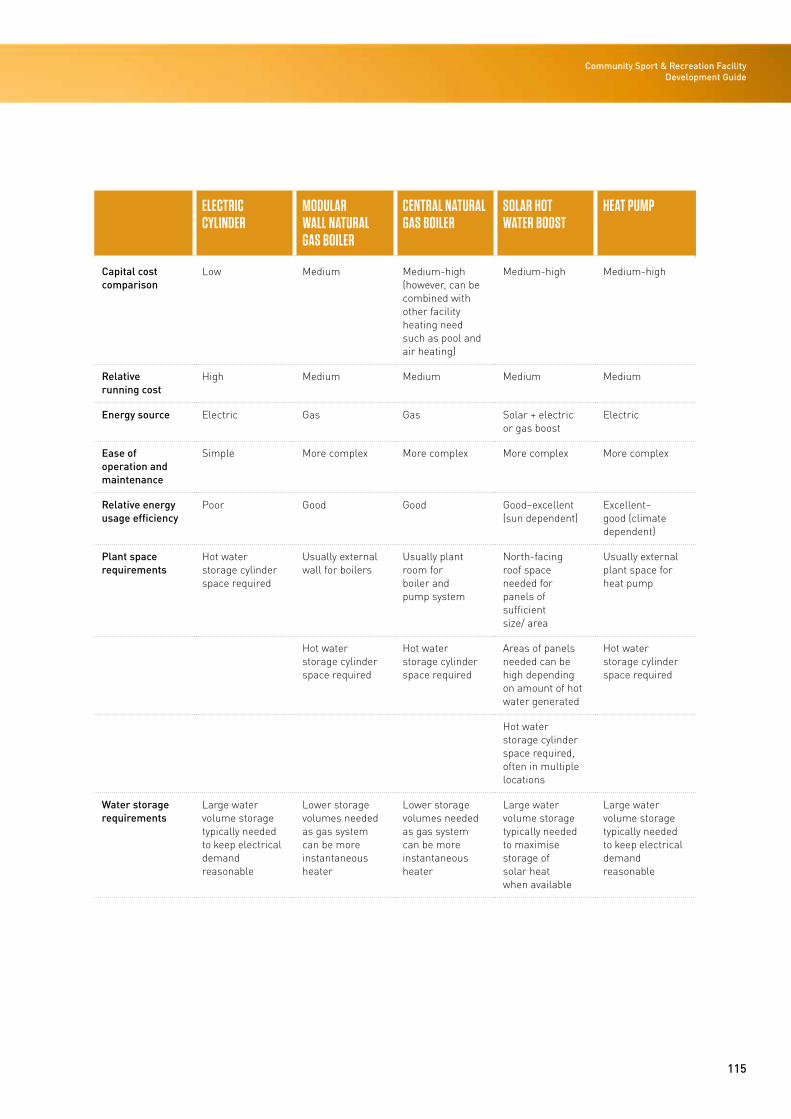
115
Community Sport & Recreation Facility Development Guide
ELECTRIC CYLINDER
MODULAR WALL NATURAL GAS BOILER
CENTRAL NATURAL GAS BOILER
SOLAR HOT WATER BOOST
HEAT PUMP
Capital cost comparison
Low Medium Medium-high (however, can be combined with other facility heating need such as pool and air heating)
Medium-high Medium-high
Relative running cost
High Medium Medium Medium Medium
Energy source Electric Gas Gas Solar + electric or gas boost
Electric
Ease of operation and maintenance
Simple More complex More complex More complex More complex
Relative energy usage efficiency
Poor Good Good Good–excellent (sun dependent)
Excellent–good (climate dependent)
Plant space requirements
Hot water storage cylinder space required
Usually external wall for boilers
Usually plant room for boiler and pump system
North-facing roof space needed for panels of sufficient size/ area
Usually external plant space for heat pump
Hot water storage cylinder space required
Hot water storage cylinder space required
Areas of panels needed can be high depending on amount of hot water generated
Hot water storage cylinder space required
Hot water storage cylinder space required, often in multiple locations
Water storage requirements
Large water volume storage typically needed to keep electrical demand reasonable
Lower storage volumes needed as gas system can be more instantaneous heater
Lower storage volumes needed as gas system can be more instantaneous heater
Large water volume storage typically needed to maximise storage of solar heat when available
Large water volume storage typically needed to keep electrical demand reasonable
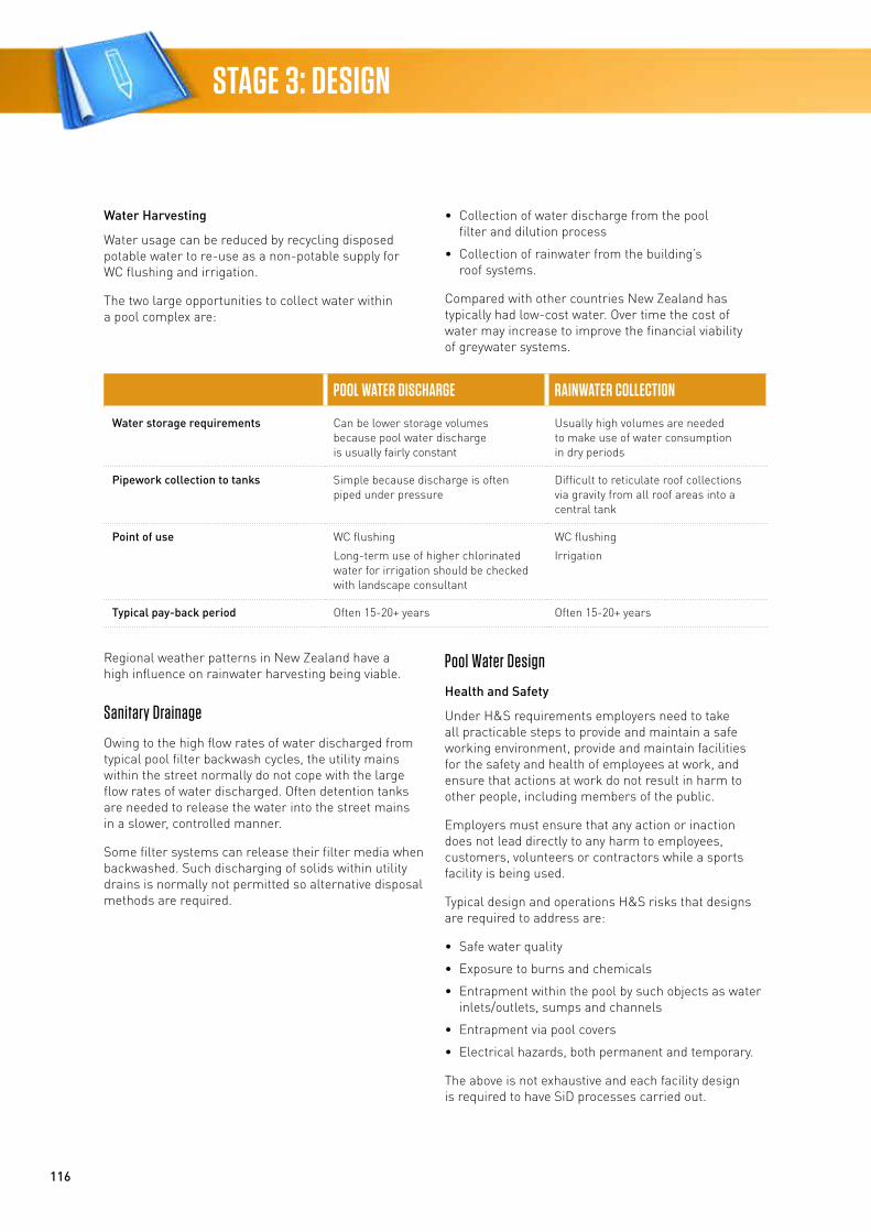
116
STAGE 3: DESIGN
Water Harvesting
Water usage can be reduced by recycling disposed potable water to re-use as a non-potable supply for WC flushing and irrigation.
The two large opportunities to collect water within a pool complex are:
• Collection of water discharge from the pool filter and dilution process
• Collection of rainwater from the building’s roof systems.
Compared with other countries New Zealand has typically had low-cost water. Over time the cost of water may increase to improve the financial viability of greywater systems.
POOL WATER DISCHARGE RAINWATER COLLECTION
Water storage requirements Can be lower storage volumes because pool water discharge is usually fairly constant
Usually high volumes are needed to make use of water consumption in dry periods
Pipework collection to tanks Simple because discharge is often piped under pressure
Difficult to reticulate roof collections via gravity from all roof areas into a central tank
Point of use WC flushing
Long-term use of higher chlorinated water for irrigation should be checked with landscape consultant
WC flushing
Irrigation
Typical pay-back period Often 15-20+ years Often 15-20+ years
Regional weather patterns in New Zealand have a high influence on rainwater harvesting being viable.
Sanitary Drainage
Owing to the high flow rates of water discharged from typical pool filter backwash cycles, the utility mains within the street normally do not cope with the large flow rates of water discharged. Often detention tanks are needed to release the water into the street mains in a slower, controlled manner.
Some filter systems can release their filter media when backwashed. Such discharging of solids within utility drains is normally not permitted so alternative disposal methods are required.
Pool Water Design
Health and Safety
Under H&S requirements employers need to take all practicable steps to provide and maintain a safe working environment, provide and maintain facilities for the safety and health of employees at work, and ensure that actions at work do not result in harm to other people, including members of the public.
Employers must ensure that any action or inaction does not lead directly to any harm to employees, customers, volunteers or contractors while a sports facility is being used.
Typical design and operations H&S risks that designs are required to address are:
• Safe water quality
• Exposure to burns and chemicals
• Entrapment within the pool by such objects as water inlets/outlets, sumps and channels
• Entrapment via pool covers
• Electrical hazards, both permanent and temporary.
The above is not exhaustive and each facility design is required to have SiD processes carried out.
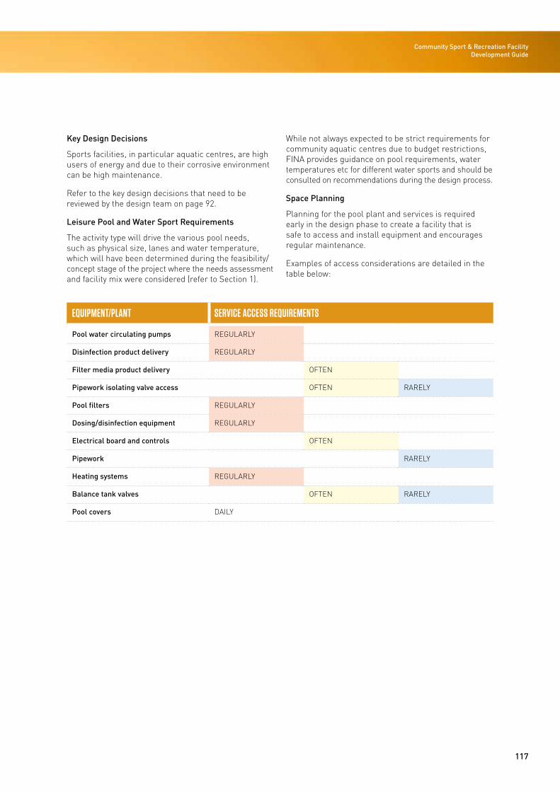
117
Community Sport & Recreation Facility Development Guide
Key Design Decisions
Sports facilities, in particular aquatic centres, are high users of energy and due to their corrosive environment can be high maintenance.
Refer to the key design decisions that need to be reviewed by the design team on page 92.
Leisure Pool and Water Sport Requirements
The activity type will drive the various pool needs, such as physical size, lanes and water temperature, which will have been determined during the feasibility/concept stage of the project where the needs assessment and facility mix were considered (refer to Section 1).
While not always expected to be strict requirements for community aquatic centres due to budget restrictions, FINA provides guidance on pool requirements, water temperatures etc for different water sports and should be consulted on recommendations during the design process.
Space Planning
Planning for the pool plant and services is required early in the design phase to create a facility that is safe to access and install equipment and encourages regular maintenance.
Examples of access considerations are detailed in the table below:
EQUIPMENT/PLANT SERVICE ACCESS REQUIREMENTS
Pool water circulating pumps REGULARLY
Disinfection product delivery REGULARLY
Filter media product delivery OFTEN
Pipework isolating valve access OFTEN RARELY
Pool filters REGULARLY
Dosing/disinfection equipment REGULARLY
Electrical board and controls OFTEN
Pipework RARELY
Heating systems REGULARLY
Balance tank valves OFTEN RARELY
Pool covers DAILY
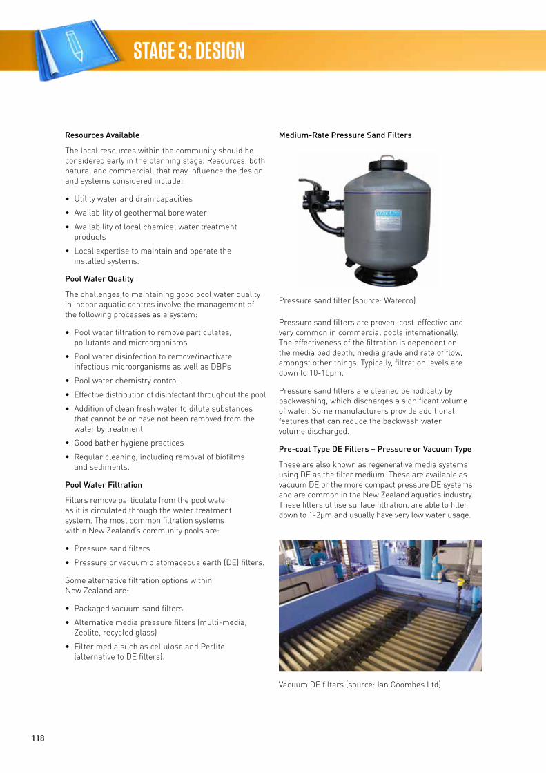
118
STAGE 3: DESIGN
Resources Available
The local resources within the community should be considered early in the planning stage. Resources, both natural and commercial, that may influence the design and systems considered include:
• Utility water and drain capacities
• Availability of geothermal bore water
• Availability of local chemical water treatment products
• Local expertise to maintain and operate the installed systems.
Pool Water Quality
The challenges to maintaining good pool water quality in indoor aquatic centres involve the management of the following processes as a system:
• Pool water filtration to remove particulates, pollutants and microorganisms
• Pool water disinfection to remove/inactivate infectious microorganisms as well as DBPs
• Pool water chemistry control
• Effective distribution of disinfectant throughout the pool
• Addition of clean fresh water to dilute substances that cannot be or have not been removed from the water by treatment
• Good bather hygiene practices
• Regular cleaning, including removal of biofilms and sediments.
Pool Water Filtration
Filters remove particulate from the pool water as it is circulated through the water treatment system. The most common filtration systems within New Zealand’s community pools are:
• Pressure sand filters
• Pressure or vacuum diatomaceous earth (DE) filters.
Some alternative filtration options within New Zealand are:
• Packaged vacuum sand filters
• Alternative media pressure filters (multi-media, Zeolite, recycled glass)
• Filter media such as cellulose and Perlite (alternative to DE filters).
Medium-Rate Pressure Sand Filters
Pressure sand filters are proven, cost-effective and very common in commercial pools internationally. The effectiveness of the filtration is dependent on the media bed depth, media grade and rate of flow, amongst other things. Typically, filtration levels are down to 10-15μm.
Pressure sand filters are cleaned periodically by backwashing, which discharges a significant volume of water. Some manufacturers provide additional features that can reduce the backwash water volume discharged.
Pre-coat Type DE Filters – Pressure or Vacuum Type
These are also known as regenerative media systems using DE as the filter medium. These are available as vacuum DE or the more compact pressure DE systems and are common in the New Zealand aquatics industry. These filters utilise surface filtration, are able to filter down to 1-2μm and usually have very low water usage.
Pressure sand filter (source: Waterco)
Vacuum DE filters (source: Ian Coombes Ltd)
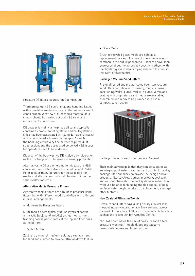
119
Community Sport & Recreation Facility Development Guide
There are some H&S operational and handling issues with some filter media such as DE that require careful consideration. A review of filter media material data sheets should be carried out and H&S risks and requirements understood.
DE powder is mainly amorphous silica and typically contains a component of crystalline silica. Crystalline silica has been associated with lung damage (silicosis) and is considered a human carcinogen. As such, the handling of this very fine powder requires dust suppression, and the associated perceived H&S issues for operators need to be addressed.
Disposal of the backwashed DE is also a consideration as the discharge of DE to sewers is usually prohibited.
Alternatives to DE are emerging to mitigate the H&S concerns. Some alternatives are cellulose and Perlite. Refer to filter manufacturers for the specific filter media and alternatives that could be used within the various filter systems.
Alternative Media Pressure Filters
Alternative media filters are similar to pressure sand filters, but with different media and often with different internal arrangements.
• Multi-media Pressure Filters
Multi-media filters typically utilise layers of coarse anthracite (top), sand (middle) and garnet (bottom), trapping coarse particulates at the top and finer ones at the bottom.
• Zeolite Media
Zeolite is a mineral medium, sold as a replacement for sand and claimed to provide filtration down to 3μm.
• Glass Media
Crushed recycled glass media are sold as a replacement for sand. The use of glass media is not common in the public pool arena. Concerns have been expressed about the potential issues for bathers, with the ‘lighter’ glass media carrying over into the pool in the event of filter failure.
Packaged Vacuum Sand Filters
Pre-engineered and prefabricated open-top vacuum sand filters complete with housing, media, internal partitioning/weirs, pump-well with pump, valves and grating with proprietary sand media are available, assembled and ready to be plumbed in, all in a compact construction.
Their main advantage is that they can be supplied as an integral pool water treatment and pool tank turnkey package. One supplier can provide the design and all products, filters, valves, pumps, pipework, pool tank and roll-out channels. The pool systems also function without a balance tank, using the rise and fall of pool surface-water height to take up displacement, amongst other features.
New Zealand Filtration Trends
Pressure sand filters have a long history of success in the pool industry internationally. They are used across the world for facilities of all types, including elite facilities such as the recent London Aquatics Centre.
NZS 4441 nominates the use of pressure sand filters, pressure-type multi-media filters and vacuum/pressure-type pre-coat filters for use.
Pressure DE filters (source: Ian Coombes Ltd)
Packaged vacuum sand filter (source: Natare)
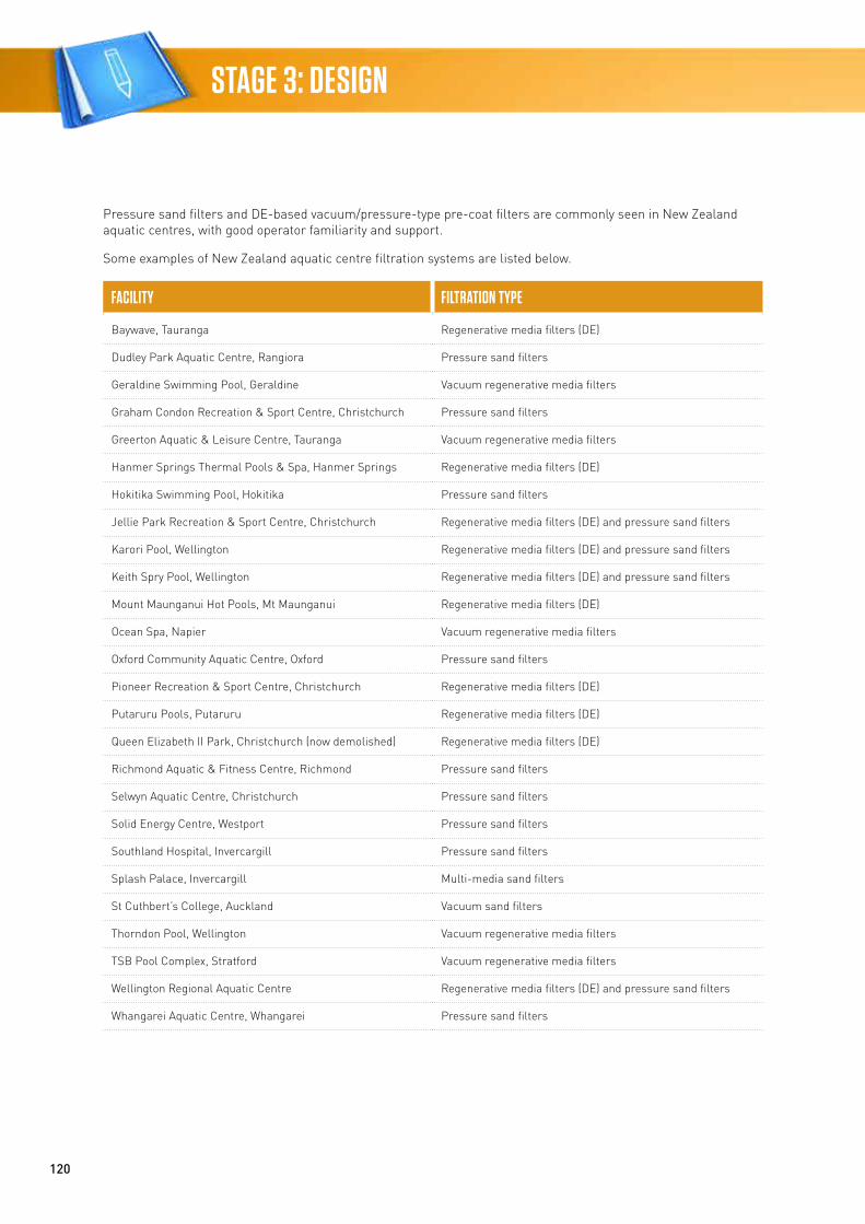
120
STAGE 3: DESIGN
Pressure sand filters and DE-based vacuum/pressure-type pre-coat filters are commonly seen in New Zealand aquatic centres, with good operator familiarity and support.
Some examples of New Zealand aquatic centre filtration systems are listed below.
FACILITY FILTRATION TYPE
Baywave, Tauranga Regenerative media filters (DE)
Dudley Park Aquatic Centre, Rangiora Pressure sand filters
Geraldine Swimming Pool, Geraldine Vacuum regenerative media filters
Graham Condon Recreation & Sport Centre, Christchurch Pressure sand filters
Greerton Aquatic & Leisure Centre, Tauranga Vacuum regenerative media filters
Hanmer Springs Thermal Pools & Spa, Hanmer Springs Regenerative media filters (DE)
Hokitika Swimming Pool, Hokitika Pressure sand filters
Jellie Park Recreation & Sport Centre, Christchurch Regenerative media filters (DE) and pressure sand filters
Karori Pool, Wellington Regenerative media filters (DE) and pressure sand filters
Keith Spry Pool, Wellington Regenerative media filters (DE) and pressure sand filters
Mount Maunganui Hot Pools, Mt Maunganui Regenerative media filters (DE)
Ocean Spa, Napier Vacuum regenerative media filters
Oxford Community Aquatic Centre, Oxford Pressure sand filters
Pioneer Recreation & Sport Centre, Christchurch Regenerative media filters (DE)
Putaruru Pools, Putaruru Regenerative media filters (DE)
Queen Elizabeth II Park, Christchurch (now demolished) Regenerative media filters (DE)
Richmond Aquatic & Fitness Centre, Richmond Pressure sand filters
Selwyn Aquatic Centre, Christchurch Pressure sand filters
Solid Energy Centre, Westport Pressure sand filters
Southland Hospital, Invercargill Pressure sand filters
Splash Palace, Invercargill Multi-media sand filters
St Cuthbert’s College, Auckland Vacuum sand filters
Thorndon Pool, Wellington Vacuum regenerative media filters
TSB Pool Complex, Stratford Vacuum regenerative media filters
Wellington Regional Aquatic Centre Regenerative media filters (DE) and pressure sand filters
Whangarei Aquatic Centre, Whangarei Pressure sand filters
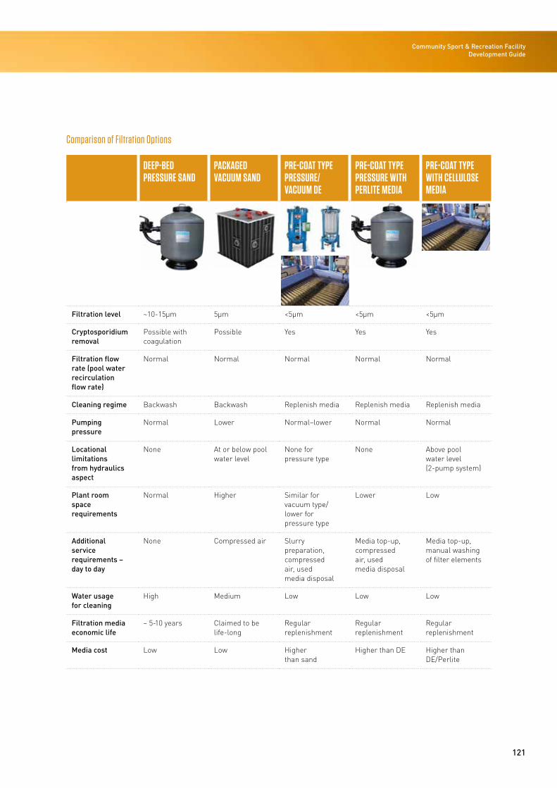
121
Community Sport & Recreation Facility Development Guide
Comparison of Filtration Options
DEEP-BED PRESSURE SAND
PACKAGED VACUUM SAND
PRE-COAT TYPE PRESSURE/ VACUUM DE
PRE-COAT TYPE PRESSURE WITH PERLITE MEDIA
PRE-COAT TYPE WITH CELLULOSE MEDIA
Filtration level ~10-15μm 5μm <5μm <5μm <5μm
Cryptosporidium removal
Possible with coagulation
Possible Yes Yes Yes
Filtration flow rate (pool water recirculation flow rate)
Normal Normal Normal Normal Normal
Cleaning regime Backwash Backwash Replenish media Replenish media Replenish media
Pumping pressure
Normal Lower Normal–lower Normal Normal
Locational limitations from hydraulics aspect
None At or below pool water level
None for pressure type
None Above pool water level (2-pump system)
Plant room space requirements
Normal Higher Similar for vacuum type/lower for pressure type
Lower Low
Additional service requirements – day to day
None Compressed air Slurry preparation, compressed air, used media disposal
Media top-up, compressed air, used media disposal
Media top-up, manual washing of filter elements
Water usage for cleaning
High Medium Low Low Low
Filtration media economic life
~ 5-10 years Claimed to be life-long
Regular replenishment
Regular replenishment
Regular replenishment
Media cost Low Low Higher than sand
Higher than DE Higher than DE/Perlite
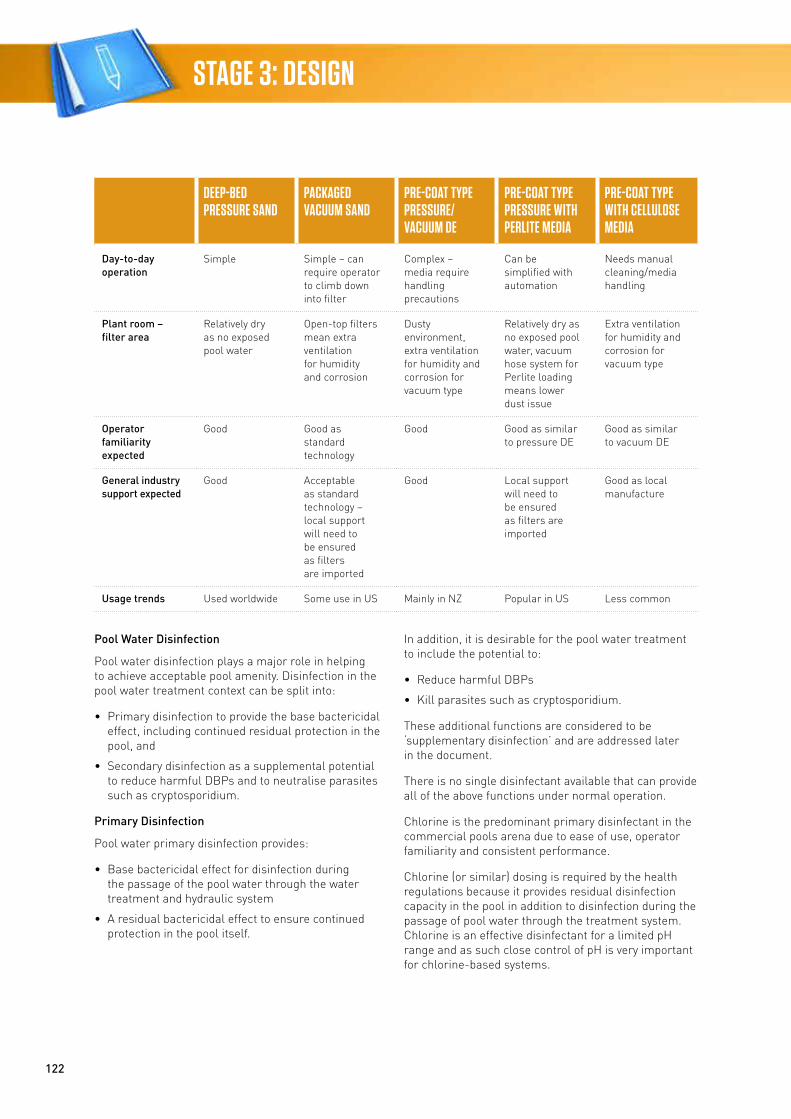
122
STAGE 3: DESIGN
DEEP-BED PRESSURE SAND
PACKAGED VACUUM SAND
PRE-COAT TYPE PRESSURE/ VACUUM DE
PRE-COAT TYPE PRESSURE WITH PERLITE MEDIA
PRE-COAT TYPE WITH CELLULOSE MEDIA
Day-to-day operation
Simple Simple – can require operator to climb down into filter
Complex – media require handling precautions
Can be simplified with automation
Needs manual cleaning/media handling
Plant room – filter area
Relatively dry as no exposed pool water
Open-top filters mean extra ventilation for humidity and corrosion
Dusty environment, extra ventilation for humidity and corrosion for vacuum type
Relatively dry as no exposed pool water, vacuum hose system for Perlite loading means lower dust issue
Extra ventilation for humidity and corrosion for vacuum type
Operator familiarity expected
Good Good as standard technology
Good Good as similar to pressure DE
Good as similar to vacuum DE
General industry support expected
Good Acceptable as standard technology – local support will need to be ensured as filters are imported
Good Local support will need to be ensured as filters are imported
Good as local manufacture
Usage trends Used worldwide Some use in US Mainly in NZ Popular in US Less common
Pool Water Disinfection
Pool water disinfection plays a major role in helping to achieve acceptable pool amenity. Disinfection in the pool water treatment context can be split into:
• Primary disinfection to provide the base bactericidal effect, including continued residual protection in the pool, and
• Secondary disinfection as a supplemental potential to reduce harmful DBPs and to neutralise parasites such as cryptosporidium.
Primary Disinfection
Pool water primary disinfection provides:
• Base bactericidal effect for disinfection during the passage of the pool water through the water treatment and hydraulic system
• A residual bactericidal effect to ensure continued protection in the pool itself.
In addition, it is desirable for the pool water treatment to include the potential to:
• Reduce harmful DBPs
• Kill parasites such as cryptosporidium.
These additional functions are considered to be ‘supplementary disinfection’ and are addressed later in the document.
There is no single disinfectant available that can provide all of the above functions under normal operation.
Chlorine is the predominant primary disinfectant in the commercial pools arena due to ease of use, operator familiarity and consistent performance.
Chlorine (or similar) dosing is required by the health regulations because it provides residual disinfection capacity in the pool in addition to disinfection during the passage of pool water through the treatment system. Chlorine is an effective disinfectant for a limited pH range and as such close control of pH is very important for chlorine-based systems.
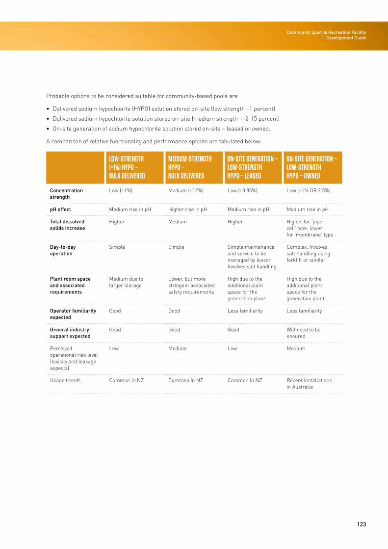
123
Community Sport & Recreation Facility Development Guide
Probable options to be considered suitable for community-based pools are:
• Delivered sodium hypochlorite (HYPO) solution stored on-site (low strength ~1 percent)
• Delivered sodium hypochlorite solution stored on-site (medium strength ~12-15 percent)
• On-site generation of sodium hypochlorite solution stored on-site – leased or owned.
A comparison of relative functionality and performance options are tabulated below:
LOW-STRENGTH (<1%) HYPO – BULK DELIVERED
MEDIUM-STRENGTH HYPO – BULK DELIVERED
ON-SITE GENERATION – LOW-STRENGTH HYPO – LEASED
ON-SITE GENERATION – LOW-STRENGTH HYPO – OWNED
Concentration strength
Low (~1%) Medium (~12%) Low (~0.85%) Low (~1% OR 2.5%)
pH effect Medium rise in pH Higher rise in pH Medium rise in pH Medium rise in pH
Total dissolved solids increase
Higher Medium Higher Higher for ‘pipe cell’ type; lower for ‘membrane’ type
Day-to-day operation
Simple Simple Simple maintenance and service to be managed by lessor. Involves salt handling
Complex. Involves salt handling using forklift or similar
Plant room space and associated requirements
Medium due to larger storage
Lower, but more stringent associated safety requirements
High due to the additional plant space for the generation plant
High due to the additional plant space for the generation plant
Operator familiarity expected
Good Good Less familiarity Less familiarity
General industry support expected
Good Good Good Will need to be ensured
Perceived operational risk level (toxicity and leakage aspects)
Low Medium Low Medium
Usage trends Common in NZ Common in NZ Common in NZ Recent installations in Australia
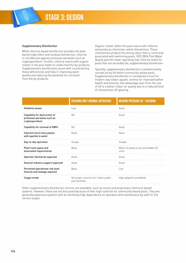
124
STAGE 3: DESIGN
Supplementary Disinfection
While chlorine-based disinfection provides the base bactericidal effect and residual disinfection, chlorine is not effective against protozoan parasites such as cryptosporidium. Further, chlorine reacts with organic matter in the pool water to create harmful by-products. Supplementary disinfectants assist with counteracting these deficiencies and help in improving water quality and reducing the potential for corrosion from the by-products.
Organic matter within the pool reacts with chlorine and produces chemicals called chloramines. These chloramines produce the strong odour that is commonly associated with swimming pools. NZS 5826 Pool Water Quality permits lower operating free chlorine levels for pools that use secondary (ie, supplementary) disinfection.
Typically, supplementary disinfection is predominantly carried out by UV within community-based pools. Supplementary disinfection is considered a must for modern-day indoor aquatic centres for improved bather health and amenity. One advantage seen from the use of UV is a better indoor air quality due to a reduced level of chloramines off-gassing.
CHLORINE ONLY (NORMAL OPERATION) MEDIUM-PRESSURE UV + CHLORINE
Oxidation power Low Good
Capability for destruction of protozoan parasites such as cryptosporidium
Nil Good
Capability for removal of DBPs Nil Good
Inherent micro-flocculation with sparkle to water
None None
Day-to-day operation Simple Simple
Plant room space and associated requirements
Base Minor increase to accommodate UV units
Operator familiarity expected Good Good
General industry support expected Good Good
Perceived operational risk level (toxicity and leakage aspects)
Base Low
Usage trends No longer common for indoor public pool facilities
High adoption worldwide
Other supplementary disinfection choices are available, such as ozone and proprietary chemical-based systems. However, these are not discussed because of their high cost/risk for community-based pools. They are generally expensive systems with an extremely high dependence on operation and maintenance by staff for the correct output.
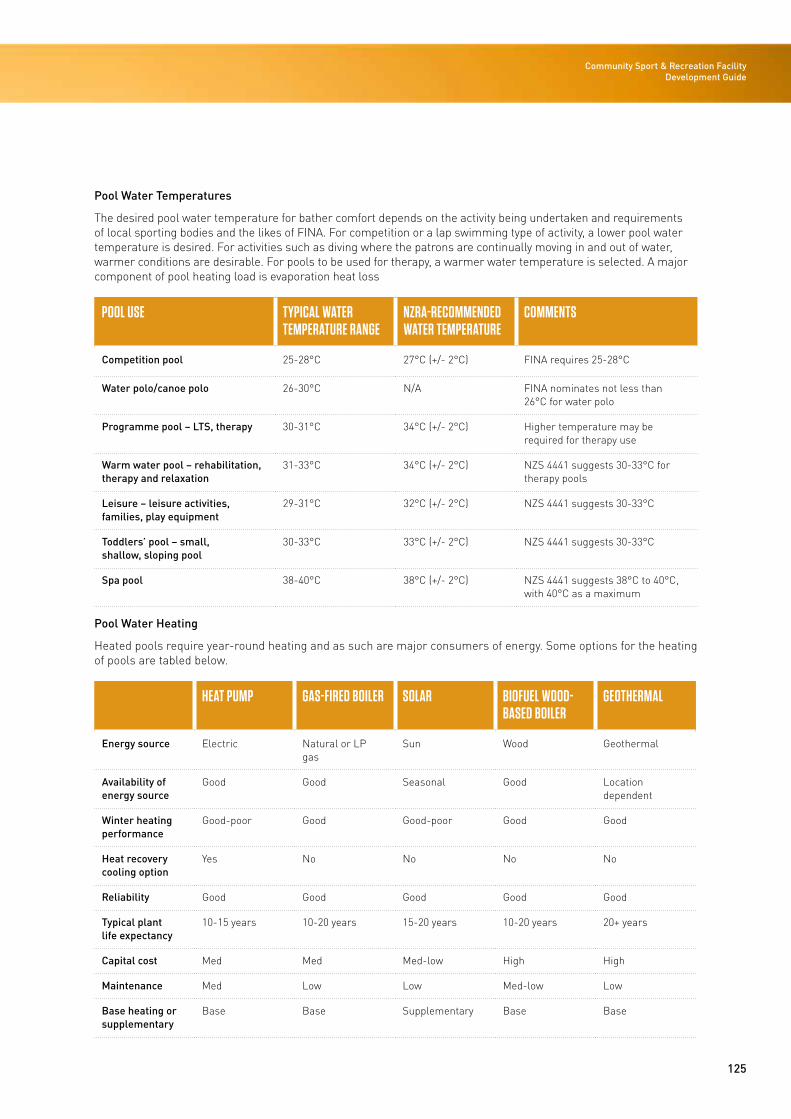
125
Community Sport & Recreation Facility Development Guide
Pool Water Temperatures
The desired pool water temperature for bather comfort depends on the activity being undertaken and requirements of local sporting bodies and the likes of FINA. For competition or a lap swimming type of activity, a lower pool water temperature is desired. For activities such as diving where the patrons are continually moving in and out of water, warmer conditions are desirable. For pools to be used for therapy, a warmer water temperature is selected. A major component of pool heating load is evaporation heat loss
POOL USE TYPICAL WATER TEMPERATURE RANGE
NZRA-RECOMMENDED WATER TEMPERATURE
COMMENTS
Competition pool 25-28°C 27°C (+/- 2°C) FINA requires 25-28°C
Water polo/canoe polo 26-30°C N/A FINA nominates not less than 26°C for water polo
Programme pool – LTS, therapy 30-31°C 34°C (+/- 2°C) Higher temperature may be required for therapy use
Warm water pool – rehabilitation, therapy and relaxation
31-33°C 34°C (+/- 2°C) NZS 4441 suggests 30-33°C for therapy pools
Leisure – leisure activities, families, play equipment
29-31°C 32°C (+/- 2°C) NZS 4441 suggests 30-33°C
Toddlers’ pool – small, shallow, sloping pool
30-33°C 33°C (+/- 2°C) NZS 4441 suggests 30-33°C
Spa pool 38-40°C 38°C (+/- 2°C) NZS 4441 suggests 38°C to 40°C, with 40°C as a maximum
Pool Water Heating
Heated pools require year-round heating and as such are major consumers of energy. Some options for the heating of pools are tabled below.
HEAT PUMP GAS-FIRED BOILER SOLAR BIOFUEL WOOD-BASED BOILER
GEOTHERMAL
Energy source Electric Natural or LP gas
Sun Wood Geothermal
Availability of energy source
Good Good Seasonal Good Location dependent
Winter heating performance
Good-poor Good Good-poor Good Good
Heat recovery cooling option
Yes No No No No
Reliability Good Good Good Good Good
Typical plant life expectancy
10-15 years 10-20 years 15-20 years 10-20 years 20+ years
Capital cost Med Med Med-low High High
Maintenance Med Low Low Med-low Low
Base heating or supplementary
Base Base Supplementary Base Base
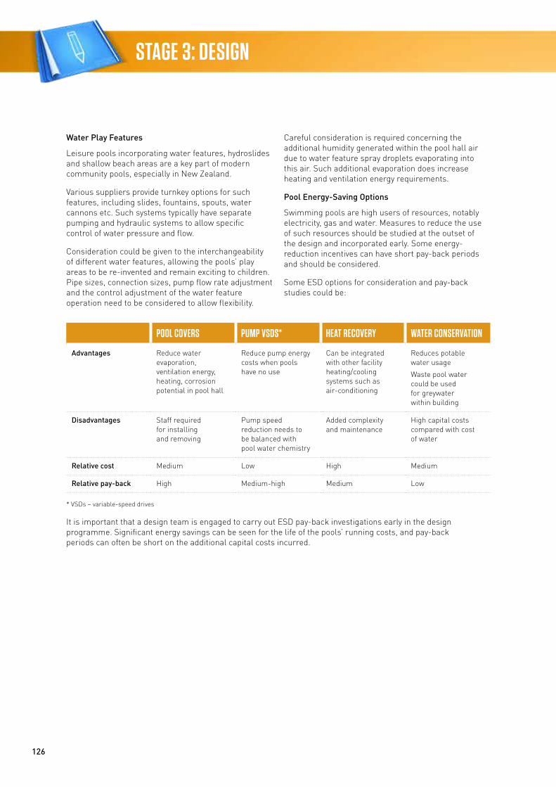
126
STAGE 3: DESIGN
Water Play Features
Leisure pools incorporating water features, hydroslides and shallow beach areas are a key part of modern community pools, especially in New Zealand.
Various suppliers provide turnkey options for such features, including slides, fountains, spouts, water cannons etc. Such systems typically have separate pumping and hydraulic systems to allow specific control of water pressure and flow.
Consideration could be given to the interchangeability of different water features, allowing the pools’ play areas to be re-invented and remain exciting to children. Pipe sizes, connection sizes, pump flow rate adjustment and the control adjustment of the water feature operation need to be considered to allow flexibility.
Careful consideration is required concerning the additional humidity generated within the pool hall air due to water feature spray droplets evaporating into this air. Such additional evaporation does increase heating and ventilation energy requirements.
Pool Energy-Saving Options
Swimming pools are high users of resources, notably electricity, gas and water. Measures to reduce the use of such resources should be studied at the outset of the design and incorporated early. Some energy-reduction incentives can have short pay-back periods and should be considered.
Some ESD options for consideration and pay-back studies could be:
POOL COVERS PUMP VSDS* HEAT RECOVERY WATER CONSERVATION
Advantages Reduce water evaporation, ventilation energy, heating, corrosion potential in pool hall
Reduce pump energy costs when pools have no use
Can be integrated with other facility heating/cooling systems such as air-conditioning
Reduces potable water usage
Waste pool water could be used for greywater within building
Disadvantages Staff required for installing and removing
Pump speed reduction needs to be balanced with pool water chemistry
Added complexity and maintenance
High capital costs compared with cost of water
Relative cost Medium Low High Medium
Relative pay-back High Medium-high Medium Low
* VSDs – variable-speed drives
It is important that a design team is engaged to carry out ESD pay-back investigations early in the design programme. Significant energy savings can be seen for the life of the pools’ running costs, and pay-back periods can often be short on the additional capital costs incurred.
127
Community Sport & Recreation Facility Development Guide
Lighting
Introduction
Interior illuminance levels will be in accordance with the recommended guidelines in AS/NZS 1680.0 Interior Lighting: Safe Movement and AS/NZS 1680.1 Interior and Workplace Lighting: General Principles and Recommendations, internationally recognised best-practice as outlined in the CIBSE Lighting Guide 4: Sports Lighting (2006) and the requirements of the applicable New Zealand sports codes and other relevant technical codes for statutory compliance. This section does not attempt to repeat information found in other standards and guidance documents, but highlights the most crucial aspects in relation to the internal lighting of community, sport and recreation facilities.
Lighting design for sports facilities is about producing good visibility that meets the requirements of the sports being played. This approach should consider both natural and artificial lighting of the facility.
Where natural lighting is to be considered this should be undertaken from the earliest planning stages of a sports facility project. This is because the glazed areas of the building must be correctly positioned and sized to achieve uniform natural illumination, which avoids glare, reflections, unwanted solar gain and heat loss.
The lighting design for all sports facilities needs to be holistic and incorporate the daylight system, artificial system and control system. Maximising the use of natural light promotes energy efficiency, but it cannot eliminate the need for artificial lighting and associated controls. Evaluating artificial lighting options involves considering quality of light, visual comfort, uniformity of illumination, lighting type, position (ceiling-mounted uplighters and/or downlighters and/or wall/track-mounted lights), energy efficiency, length of life, radiation of heat, initial and ongoing costs, and ease of cleaning and replacement.
Achieving uniformity of illumination in these spaces is important and requires eliminating dark areas.
Apart from such special requirements, consideration should be given to standardising the light fittings as much as possible to reduce the quantities and varieties of spares that must be stored on-site so as to simplify maintenance and replacement. It is recommended that the lamp sources to be used throughout these facilities be LED (light-emitting diode), except where in specialist circumstances light fittings using LED technology
are not available. LED fittings can provide benefits in relation to significantly reduced energy consumption and longer lamp-life maintenance costs. They may incur a larger initial capital cost (this aspect is now reducing significantly with the technology advancement and popularity of the use of LEDs), but they will provide better value over the lifetime of the building (whole-of-life cost) and generally pay-back in less than 10 years. Fittings installed within a common area are to be specified with LEDs from the same manufacturing batch to ensure commonality of colour, temperature and performance.
In all instances, provision must be made for safe access to the lighting and to glazed areas, such as roof lights, for cleaning, maintenance, repair and replacement.
Lighting in Aquatic Facilities
General
Swimming pool lighting caters for a variety of visual tasks. The competitive swimmer has a much different seeing task from other swimmers where the main attention is focused on staying in the lane and the turning point at the end of the lane. Water polo players need lighting with a good ambient lighting effect. Swimming instructors, coaches, pool attendants and spectators all need to see across the pool and into the water to identify swimmers and situations. For recreational swimming pools and water leisure spaces, themed or decorative lighting effects may be required (these can be provided by pre-wired, weatherproof outlets at strategic locations, allowing the connection of themed lighting in the future or for special events).
The recommended levels of illuminance for swimming pools are 300 lux for most activities and 500 lux for competition. For international events, FINA requires 600 lux at the start and turn ends of the pool and this will be significantly more to accommodate TV broadcasting. As this document is focused on community facilities, the additional lighting requirements for international events and broadcasting are not covered further.
There are a number of specific design aspects to be considered for lighting pools and aquatic facilities. These include:
• Reflectance and glare
• Luminaire types
• Access for maintenance
• Direct lighting
• Indirect lighting.
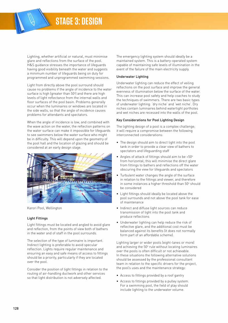
128
STAGE 3: DESIGN
Lighting, whether artificial or natural, must minimise glare and reflections from the surface of the pool. H&S guidance stresses the importance of lifeguards having good visibility beneath the water and suggests a minimum number of lifeguards being on duty for programmed and unprogrammed swimming sessions.
Light from directly above the pool surround should cause no problems if the angle of incidence to the water surface is high (greater than 50o) and there are high levels of light reflectance from the internal walls and floor surfaces of the pool basin. Problems generally occur when the luminaires or windows are located in the side walls, so that the angle of incidence causes problems for attendants and spectators.
When the angle of incidence is low, and combined with the wave action on the water, the reflection patterns on the water surface can make it impossible for lifeguards to see swimmers below the water surface who might be in difficulty. This will depend upon the geometry of the pool hall and the location of glazing and should be considered at an early design stage.
Light Fittings
Light fittings must be located and angled to avoid glare and reflection, from the points of view both of bathers in the water and of staff in the pool surrounds.
The selection of the type of luminaire is important. Indirect lighting is preferable to avoid specular reflection. Lights require regular maintenance and ensuring an easy and safe means of access to fittings should be a priority, particularly if they are located over the pool.
Consider the position of light fittings in relation to the routing of air-handling ductwork and other services so that light distribution is not adversely affected.
The emergency lighting system should ideally be a maintained system. This is a battery-operated system capable of maintaining safe levels of illumination in the event of the failure of the main electricity supply.
Underwater Lighting
Underwater lighting can reduce the effect of veiling reflections on the pool surface and improve the general evenness of illumination below the surface of the water. This can increase pool safety and help coaches to study the techniques of swimmers. There are two basic types of underwater lighting: ‘dry niche’ and ‘wet niche’. Dry niches contain luminaires behind watertight portholes and wet niches are recessed into the walls of the pool.
Key Considerations for Pool Lighting Design
The lighting design of a pool is a complex challenge; it will require a compromise between the following interconnected considerations:
• The design should aim to direct light into the pool tank in order to provide a clear view of bathers to spectators and lifeguarding staff
• Angles of attack of fittings should aim to be >50o from horizontal; this will minimise the direct glare from fittings to bathers and reflections off the water obscuring the view for lifeguards and spectators
• Turbulent water changes the angle of the surface in relation to the fittings and viewer, and therefore in some instances a higher threshold than 50o should be considered
• Light fittings should ideally be located above the pool surrounds and not above the pool tank for ease of maintenance
• Indirect and diffuse light sources can reduce transmission of light into the pool tank and produce reflections
• Underwater lighting can help reduce the risk of reflective glare, and the additional cost must be balanced against its benefits (it does not normally form part of an affordable scheme).
Lighting larger or wider pools (eight-lanes or more) and achieving the 50o rule without locating luminaires over the pools is often difficult or not achievable. In these situations the following alternative solutions should be assessed by the professional consultant team in relation to the specific drivers for the project, the pool’s uses and the maintenance strategy:
• Access to fittings provided by a roof gantry
• Access to fittings provided by a pulley system. For a swimming pool, the field of play should include lighting to the underwater volume.
Karori Pool, Wellington
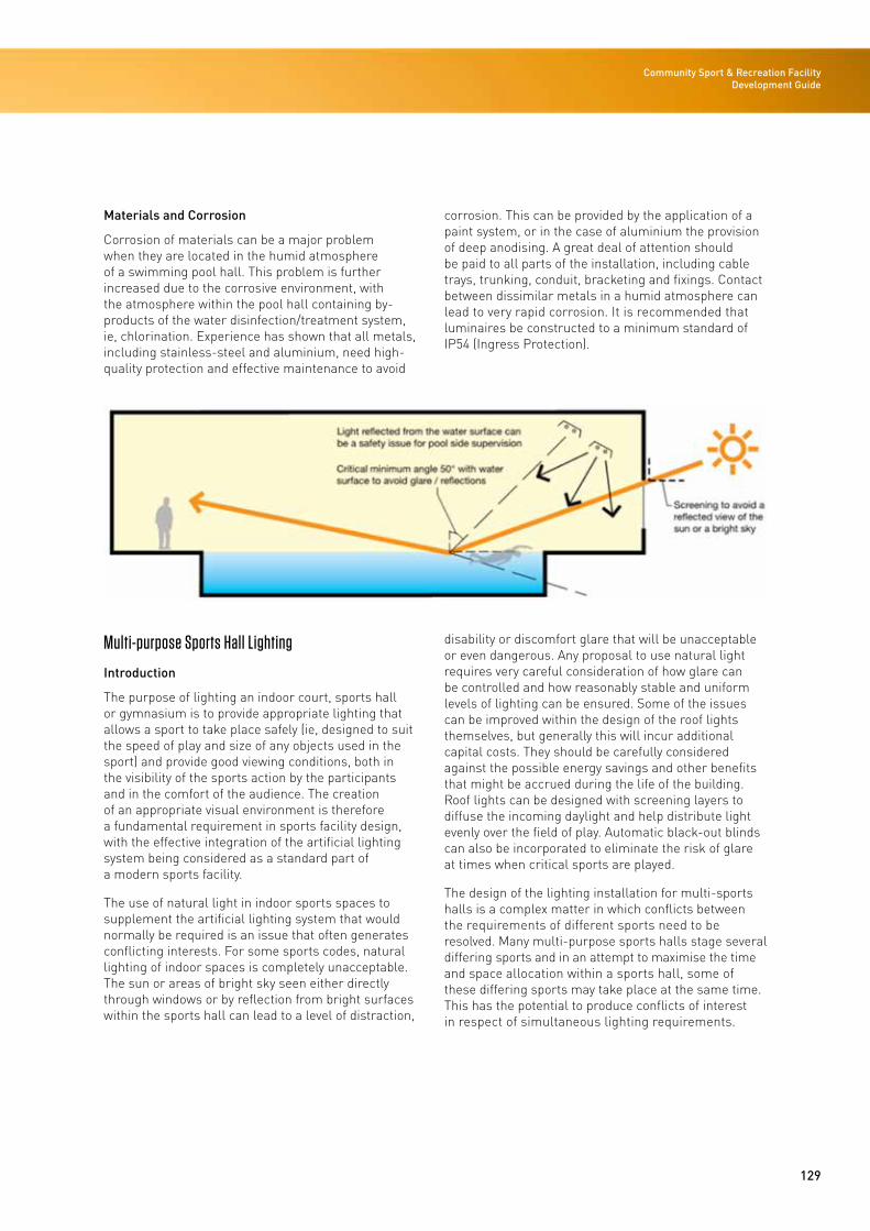
129
Community Sport & Recreation Facility Development Guide
Materials and Corrosion
Corrosion of materials can be a major problem when they are located in the humid atmosphere of a swimming pool hall. This problem is further increased due to the corrosive environment, with the atmosphere within the pool hall containing by-products of the water disinfection/treatment system, ie, chlorination. Experience has shown that all metals, including stainless-steel and aluminium, need high-quality protection and effective maintenance to avoid
corrosion. This can be provided by the application of a paint system, or in the case of aluminium the provision of deep anodising. A great deal of attention should be paid to all parts of the installation, including cable trays, trunking, conduit, bracketing and fixings. Contact between dissimilar metals in a humid atmosphere can lead to very rapid corrosion. It is recommended that luminaires be constructed to a minimum standard of IP54 (Ingress Protection).
Multi-purpose Sports Hall Lighting
Introduction
The purpose of lighting an indoor court, sports hall or gymnasium is to provide appropriate lighting that allows a sport to take place safely (ie, designed to suit the speed of play and size of any objects used in the sport) and provide good viewing conditions, both in the visibility of the sports action by the participants and in the comfort of the audience. The creation of an appropriate visual environment is therefore a fundamental requirement in sports facility design, with the effective integration of the artificial lighting system being considered as a standard part of a modern sports facility.
The use of natural light in indoor sports spaces to supplement the artificial lighting system that would normally be required is an issue that often generates conflicting interests. For some sports codes, natural lighting of indoor spaces is completely unacceptable. The sun or areas of bright sky seen either directly through windows or by reflection from bright surfaces within the sports hall can lead to a level of distraction,
disability or discomfort glare that will be unacceptable or even dangerous. Any proposal to use natural light requires very careful consideration of how glare can be controlled and how reasonably stable and uniform levels of lighting can be ensured. Some of the issues can be improved within the design of the roof lights themselves, but generally this will incur additional capital costs. They should be carefully considered against the possible energy savings and other benefits that might be accrued during the life of the building. Roof lights can be designed with screening layers to diffuse the incoming daylight and help distribute light evenly over the field of play. Automatic black-out blinds can also be incorporated to eliminate the risk of glare at times when critical sports are played.
The design of the lighting installation for multi-sports halls is a complex matter in which conflicts between the requirements of different sports need to be resolved. Many multi-purpose sports halls stage several differing sports and in an attempt to maximise the time and space allocation within a sports hall, some of these differing sports may take place at the same time. This has the potential to produce conflicts of interest in respect of simultaneous lighting requirements.
130
STAGE 3: DESIGN
There must, however, be flexibility within a lighting installation that will allow selective switching and/or other methods of control to satisfy the demands of differing sports that may be played at varying levels of competition.
As a result of the often significant diversity of lighting requirements between sports within a multi-purpose sports hall, it is usually recommended that the activity with the most stringent lighting requirements be used as the basis for lighting design. The demands of other sports should, however, be met wherever practical. Where there is limited information on the likely usage of a sports hall, it is generally recommended that a scheme be designed to suit the most common use, usually basketball, netball or badminton. It is important to be aware that sport lighting requirements may involve luminaire placement, vertically and in the horizontal plane, as well as lighting levels. The requirements of different sports may well be incompatible and this can lead to a need for, effectively, multiple lighting installations in one hall. Switching arrangements for the simultaneous use of a sports hall for different sports are likely to be complex and will need to be considered carefully.
The recommended illumination for a general multi-sport indoor court/sports hall is 500 lux; this includes the provision to switch down to 300 lux as required and is considered to be the most appropriate for a facility that aims to cater for a full programme of community sporting activities, including training and competition. The options for adding further switchable lighting for badminton, volleyball and other key indoor sports should be considered and assessed during the needs analysis planning of the facility.
Key Considerations for the Lighting Design
It is important that the lighting requirements of each sport proposed to be played in a multi-purpose sports hall are fully understood at the outset of the project. This requires an understanding of the nature of the sporting activity and key characteristics, eg, speed of play and size of objects (balls, shuttlecocks etc) as follows:
• Level of illumination – should be appropriate for a particular sport and should be checked with the requirements of the sports code or the organisation that is promoting a particular event. This can vary with the level of play and competition
• Even illumination – the full volume of the field of play should be illuminated evenly to create equal playing conditions for all players and a consistent level of visibility
• Volume of the field of play – with court/indoor sports the lighting design needs to consider the whole of the 3D volume above and including the field of play
• Brightness and contrast – suitable brightness and contrast over the playing area, sufficient light at all points, correct distribution of light and adequate control of glare. Playing objects will be seen because they contrast with their backgrounds in brightness, colour or both. The more marked the contrast, the more clearly objects are perceived in general. For instance, for badminton a reduction in illumination behind the court is preferred to achieve an acceptable background contrast
• Colour rendering – good colour rendering is essential to differentiate between opposing competitors or teams, and many sports use colour and colour contrast to improve the visibility of sports equipment or differentiate various aspects of the playing area or target
• Glare – as many sports also place restrictions on the positioning of luminaires with respect to the playing area to minimise glare and distraction, this requires careful design. For basketball and netball, the luminaires directly above the goal/net within a 4m diameter should not be switched on. For aerial sports, eg, badminton and volleyball, the positioning of luminaires outside the playing area may be necessary to avoid disability glare for players looking upwards.
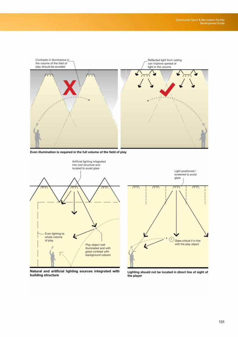
131
Community Sport & Recreation Facility Development Guide
132
STAGE 3: DESIGN
Specific Luminaire Considerations
The selection of luminaires for multi-purpose sports halls needs to consider a number of key points. When a sport involves a fast-moving target, the elimination of any stroboscopic effect (where LED light sources are not used) from high-intensity discharge sources is important. Stroboscopic effects may make a moving object appear stationary, or make the object seem to jump from one position to another. For these sports, the use of high-frequency control gear is recommended.
Consideration should be given to the environment and the nature of the sport(s) to be played in the facility with respect to shielding the luminaires and/or the use of impact-resistant covers. If struck by a ball, a luminaire must withstand the impact and any damage that might otherwise cause component parts to fall to the ground. Care must be taken to ensure that the grid dimensions of the lamp enclosure are substantially smaller than objects that may be used, eg, balls or shuttlecocks, so that they cannot lodge in the fitting or its protective grille.
Luminaire mounting options need to be considered and integrated as part of the design process. The structural design of a sports facility may place restrictions, both in the positioning of luminaires and in luminaire weight, as some structures have limited weight-bearing capabilities. The lighting designer will be responsible for coordinating with the structural engineer.
Lighting Control
For a multi-purpose sports hall, the base lighting scheme should include a flexible arrangement using manual switching to provide various configurations of light levels from 500 lux to 300 lux. The luminaires in the enhanced lighting scheme that achieves 500 lux, which are required to be switched on/off, should be arranged in separate circuits. A bank of labelled switches should be provided in a panel with the required lighting arrangements clearly marked.
Other enhanced automated options for controlling the lighting to a multi-purpose sports hall can be provided and, where possible, should be considered. These provide better control, flexibility and energy savings and include:
• Fully addressable lighting control system – a control system could be provided wherein each luminaire can be addressed individually and have a dimmable ballast. The lighting could then be controlled from a scene-setting switch panel with a range of buttons or with dimmable options
• Energy-saving option – the above system can be supplemented with occupancy sensors. The sensors detect the occupancy (presence/absence of people) in a space and automatically switch off the lighting after a pre-set period of inactivity
• Daylight dimming option – the above system can be supplemented with daylight dimming if natural lighting through roof lights, or similar, with automatic blinds is introduced to the space. The system measures the amount of daylight light present under each row of luminaires, and automatically adjusts the output of the luminaires so that the sum of the daylight and artificial light gives the required illumination as per the scene selected.
The following are the main advantages of having an automated lighting control system:
• The lighting circuit and wiring are much simpler than the manual control option
• Any changes to the system in terms of additional luminaires, different groupings of luminaires, different lighting levels etc can at a later date be accommodated easily, unlike manual control, which will be very difficult or not possible
• With lower-lux-level lighting set-ups and daylight dimming, the lamps will last longer, as they are being dimmed down and driven at lower output, thereby reducing energy and maintenance costs
• The system can be interfaced with an occupancy-sensing PIR insulation board in the sports hall, which will further enhance energy savings by switching off the lights after a fixed period of inactivity in the hall.
With manual switching the various lighting control arrangements will need a suitably rated contractor for switching the lighting circuit. With the lighting control system contactors are not required as the fittings are controlled independently to provide full flexibility with rearranging the lighting control zones.
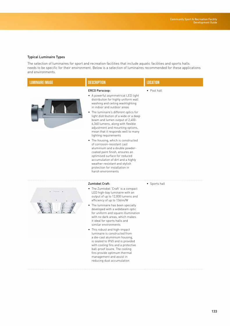
133
Community Sport & Recreation Facility Development Guide
Typical Luminaire Types
The selection of luminaires for sport and recreation facilities that include aquatic facilities and sports halls needs to be specific for their environment. Below is a selection of luminaires recommended for these applications and environments.
LUMINAIRE IMAGE DESCRIPTION LOCATION
ERCO Parscoop:
• A powerful asymmetrical LED light distribution for highly uniform wall washing and ceiling washlighting in indoor and outdoor areas
• The luminaire’s different optics for light distribution of a wide or a deep beam and lumen output of 2,400-6,360 lumens, along with flexible adjustment and mounting options, mean that it responds well to many lighting requirements
• The housing, which is constructed of corrosion-resistant cast aluminium and a double powder-coated paint finish, ensures an optimised surface for reduced accumulation of dirt and a highly weather-resistant and stylish protection for installation in harsh environments
• Pool hall
Zumtobel Craft:
• The Zumtobel ‘Craft’ is a compact LED high-bay luminaire with an output of up to 12,000 lumens and efficiency of up to 136lm/W
• The luminaire has been specially developed with a widebeam optic for uniform and square illumination with no dark areas, which makes it ideal for sports halls and similar environments
• This robust and high-impact luminaire is constructed from a die-cast aluminium housing, is sealed to IP65 and is provided with cooling fins and a protective ball-proof louvre. The cooling fins provide optimum thermal management and assist in reducing dust accumulation
• Sports hall
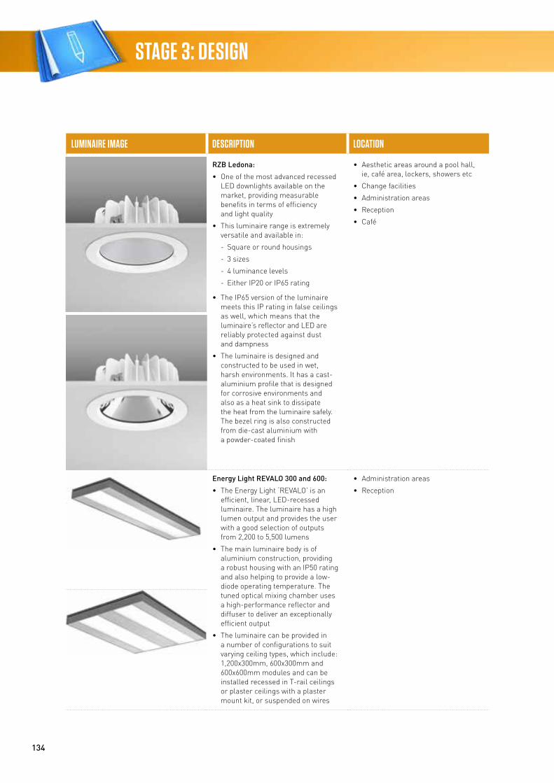
134
STAGE 3: DESIGN
LUMINAIRE IMAGE DESCRIPTION LOCATION
RZB Ledona:
• One of the most advanced recessed LED downlights available on the market, providing measurable benefits in terms of efficiency and light quality
• This luminaire range is extremely versatile and available in:
- Square or round housings
- 3 sizes
- 4 luminance levels
- Either IP20 or IP65 rating
• The IP65 version of the luminaire meets this IP rating in false ceilings as well, which means that the luminaire’s reflector and LED are reliably protected against dust and dampness
• The luminaire is designed and constructed to be used in wet, harsh environments. It has a cast-aluminium profile that is designed for corrosive environments and also as a heat sink to dissipate the heat from the luminaire safely. The bezel ring is also constructed from die-cast aluminium with a powder-coated finish
• Aesthetic areas around a pool hall, ie, café area, lockers, showers etc
• Change facilities
• Administration areas
• Reception
• Café
Energy Light REVALO 300 and 600:
• The Energy Light ‘REVALO’ is an efficient, linear, LED-recessed luminaire. The luminaire has a high lumen output and provides the user with a good selection of outputs from 2,200 to 5,500 lumens
• The main luminaire body is of aluminium construction, providing a robust housing with an IP50 rating and also helping to provide a low-diode operating temperature. The tuned optical mixing chamber uses a high-performance reflector and diffuser to deliver an exceptionally efficient output
• The luminaire can be provided in a number of configurations to suit varying ceiling types, which include: 1,200x300mm, 600x300mm and 600x600mm modules and can be installed recessed in T-rail ceilings or plaster ceilings with a plaster mount kit, or suspended on wires
• Administration areas
• Reception
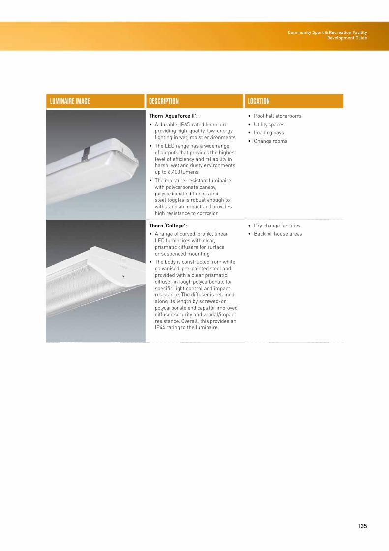
135
Community Sport & Recreation Facility Development Guide
LUMINAIRE IMAGE DESCRIPTION LOCATION
Thorn ‘AquaForce II’:
• A durable, IP65-rated luminaire providing high-quality, low-energy lighting in wet, moist environments
• The LED range has a wide range of outputs that provides the highest level of efficiency and reliability in harsh, wet and dusty environments up to 6,400 lumens
• The moisture-resistant luminaire with polycarbonate canopy, polycarbonate diffusers and steel toggles is robust enough to withstand an impact and provides high resistance to corrosion
• Pool hall storerooms
• Utility spaces
• Loading bays
• Change rooms
Thorn ‘College’:
• A range of curved-profile, linear LED luminaires with clear, prismatic diffusers for surface or suspended mounting
• The body is constructed from white, galvanised, pre-painted steel and provided with a clear prismatic diffuser in tough polycarbonate for specific light control and impact resistance. The diffuser is retained along its length by screwed-on polycarbonate end caps for improved diffuser security and vandal/impact resistance. Overall, this provides an IP44 rating to the luminaire
• Dry change facilities
• Back-of-house areas

Community Sport & Recreation Facility Development Guide / 2016
STAGE 4
STAGE 4: BUILD Community Sport & Recreation Facility Development Guide
Procurement of ContractorsThe procurement of a contractor is outlined below and covers:
• The procurement process
• Selection of a contractor
• Contract form and payment mechanism
• Evaluation criteria (selection criteria and weightings).
Contractor Procurement Process
Contractor procurement can be undertaken via a two-step process (pre-qualification via expressions of interest or a pre-approved panel and a request for proposals) or a single step (request for proposals). Local government agencies may have suitable pre-approved panels instead of a separate pre-qualification process.
The important factor to consider is that the respondents to a request for proposals have the ability to undertake the work, and have specific sports facility experience.
Contractor Procurement Route Options
APPROACH SUMMARY COMMENTS
Expression of Interest and tender
Documentation
1. Expression of interest issued (the party leading the project) to open market
2. Response to the expression of interest (prepared by the contractor)
3. Evaluation and shortlist (typically 2-4 parties)
4. Request for tender issued (typically 2-4 parties) (from the party leading the project)
5. Response to the tender (prepared by the contractor)
6. Evaluation and selection
• Typical timeframe including evaluation and selection 12-16 weeks
• 70% of the time will be response preparation by contractor
• 30% of the time will be assessment, evaluation and selection of contractor
• Note additional time to prepare response documents is required
Tender only Documentation
1. Request for tender (the party leading the project)
2. Response to the tender (prepared by the contractor)
• Typical timeframe including evaluation and selection 6-8 weeks
• 70% of the time will be contractor preparation
• 30% of the time will be assessment, evaluation and selection of contractor
137
138
Contracting Type
The procurement strategy will also outline the preferred contracting type. The preferred contracting type establishes the framework for the life-cycle delivery of the project (ie, how its management, design and construction will be commissioned). There are several delivery models available, which represent varying degrees of complexity, risk, innovation, client involvement and programme influence. These are summarised for construction in the table below.
Delivery Model Summary – Construction
DELIVERY MODEL DESCRIPTION
1 Alliance A partnership between the owner, consultant and contractor. This method of procurement is directed towards aligning the goals of all parties so that decisions are made in the best interests of the project
2 Design and build The owner contracts to a single entity (company or consortium) that is responsible for the design and construction or implementation of the project
3 Traditional The owner engages a consulting engineer to design and specify a project, then calls for tenders for the construction or implementation
1 Australian Consulting Engineering Association (ACEA) Practice Note PN 4.05.2 ACEA Practice Note PN 4.05.3 ACEA Practice Note PN 4.05.
Practice notes and guidelines advise engineers and others on practice-related issues.
Selection of Contractor
Approach to Selecting Contractors
Once a procurement route has been decided, the following outlines the approach to selecting a contractor:
• Contract structure
• Contract type
• Payment mechanism
• Typical selection criteria.
A critical part of this process is selecting a client project manager/quantity surveyor to manage works.
It is important when deciding on the contractor selection to consider the following points:
• Selection on preliminary and general costs, plus profit and margin and risks
• Evaluation panel with representatives from, facility operations, technical, property etc to reflect the owner’s requirements
• Undertaking early contractor involvement (ECI) is essentially a form of collaborative contracting. As its name suggests ECI envisages early involvement of the contractor and the adoption of ‘best for project’ approaches by all parties.
• Within the ECI scope it is important to agree the deliverables, cost schedule, key risks and trade letting schedule at the outset
• Needs to include insurances for entire term of contract
• Single head contract
• Lump sum payments, payments by results for achieving outcomes and performance bonuses are options.
STAGE 4: BUILD
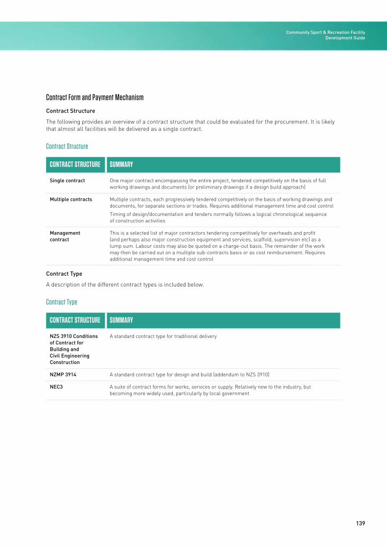
139
Contract Form and Payment Mechanism
Contract Structure
The following provides an overview of a contract structure that could be evaluated for the procurement. It is likely that almost all facilities will be delivered as a single contract.
Contract Structure
CONTRACT STRUCTURE SUMMARY
Single contract One major contract encompassing the entire project, tendered competitively on the basis of full working drawings and documents (or preliminary drawings if a design build approach)
Multiple contracts Multiple contracts, each progressively tendered competitively on the basis of working drawings and documents, for separate sections or trades. Requires additional management time and cost control
Timing of design/documentation and tenders normally follows a logical chronological sequence of construction activities
Management contract
This is a selected list of major contractors tendering competitively for overheads and profit (and perhaps also major construction equipment and services, scaffold, supervision etc) as a lump sum. Labour costs may also be quoted on a charge-out basis. The remainder of the work may then be carried out on a multiple sub-contracts basis or as cost reimbursement. Requires additional management time and cost control
Contract Type
A description of the different contract types is included below.
Contract Type
CONTRACT STRUCTURE SUMMARY
NZS 3910 Conditions of Contract for Building and Civil Engineering Construction
A standard contract type for traditional delivery
NZMP 3914 A standard contract type for design and build (addendum to NZS 3910)
NEC3 A suite of contract forms for works, services or supply. Relatively new to the industry, but becoming more widely used, particularly by local government
Community Sport & Recreation Facility Development Guide
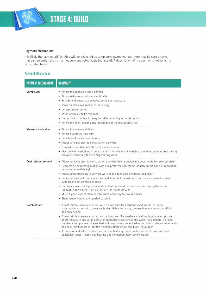
140
Payment Mechanism
It is likely that almost all facilities will be delivered as lump sum payments, but there may be scope items that can be undertaken on a measure and value basis (eg, plant). A description of the payment mechanisms is included below.
Payment Mechanism
PAYMENT MECHANISM SUMMARY
Lump sum • Where the scope is clearly defined
• Where risks are small and identifiable
• Schedule of prices can be used, but is not necessary
• Tenderer does own measure for pricing
• Longer tender period
• Variations likely to be minimal
• Higher risk to contractor may be reflected in higher tender price
• Where the client needs early knowledge of the final project cost
Measure and value • Where the scope is defined
• Where quantities may vary
• Schedule of prices is necessary
• Allows an early start to construction activities
• Normally equitable to both client and contractor
• May allow for variations in construction methods to suit variable conditions encountered during the work, especially for civil engineering work
Cost reimbursement • Allows an early start to construction activities before design and documentation are complete
• Requires selection/negotiation with one preferred contractor (usually on the basis of reputation or resource availability)
• Allows great flexibility to vary the work or to speed up/slow down the project
• Final costs are not fixed and it can be difficult to forecast out-turn costs for project unless suitable project controls in place
• Commonly used for high-risk work so that the client carries the risks, paying the actual resultant costs rather than a premium for risk protection
• Much higher level of client involvement in the day-to-day decisions
• Short tender/negotiation period possible
Combination • A cost reimbursement contract with a lump sum for overheads and profit. The lump sum may be extended to cover such identifiable items as; construction equipment; scaffold and supervision
• A cost reimbursement contract with a lump sum for overheads and profit, plus a lump sum and/or measure and value items for appropriate sections of the work. For example, a project may have: lump sums for specified buildings; measure and value items for civil/structural work; and cost reimbursement for the mechanical/electrical and plant installation
• A measure and value contract for civil and building trades, with a series of lump sums for specialist trades – electrical, heating and ventilation, floor coverings etc
STAGE 4: BUILD
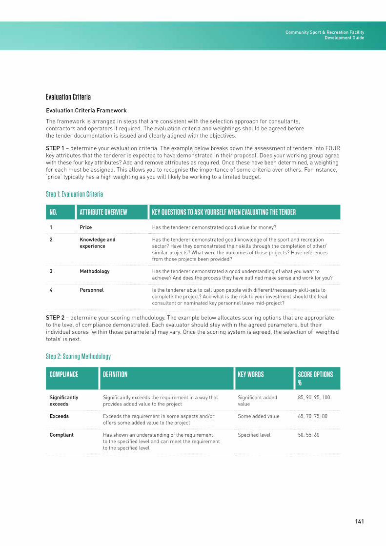
141
Evaluation Criteria
Evaluation Criteria Framework
The framework is arranged in steps that are consistent with the selection approach for consultants, contractors and operators if required. The evaluation criteria and weightings should be agreed before the tender documentation is issued and clearly aligned with the objectives.
STEP 1 – determine your evaluation criteria. The example below breaks down the assessment of tenders into FOUR key attributes that the tenderer is expected to have demonstrated in their proposal. Does your working group agree with these four key attributes? Add and remove attributes as required. Once these have been determined, a weighting for each must be assigned. This allows you to recognise the importance of some criteria over others. For instance, ‘price’ typically has a high weighting as you will likely be working to a limited budget.
Step 1: Evaluation Criteria
NO. ATTRIBUTE OVERVIEW KEY QUESTIONS TO ASK YOURSELF WHEN EVALUATING THE TENDER
1 Price Has the tenderer demonstrated good value for money?
2 Knowledge and experience
Has the tenderer demonstrated good knowledge of the sport and recreation sector? Have they demonstrated their skills through the completion of other/similar projects? What were the outcomes of those projects? Have references from those projects been provided?
3 Methodology Has the tenderer demonstrated a good understanding of what you want to achieve? And does the process they have outlined make sense and work for you?
4 Personnel Is the tenderer able to call upon people with different/necessary skill-sets to complete the project? And what is the risk to your investment should the lead consultant or nominated key personnel leave mid-project?
STEP 2 – determine your scoring methodology. The example below allocates scoring options that are appropriate to the level of compliance demonstrated. Each evaluator should stay within the agreed parameters, but their individual scores (within those parameters) may vary. Once the scoring system is agreed, the selection of ‘weighted totals’ is next.
Step 2: Scoring Methodology
COMPLIANCE DEFINITION KEY WORDS SCORE OPTIONS %
Significantly exceeds
Significantly exceeds the requirement in a way that provides added value to the project
Significant added value
85, 90, 95, 100
Exceeds Exceeds the requirement in some aspects and/or offers some added value to the project
Some added value 65, 70, 75, 80
Compliant Has shown an understanding of the requirement to the specified level and can meet the requirement to the specified level
Specified level 50, 55, 60
Community Sport & Recreation Facility Development Guide
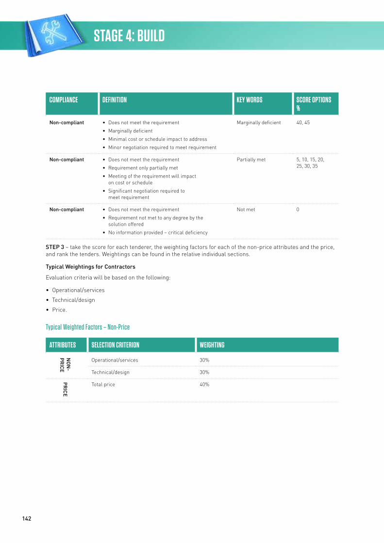
142
COMPLIANCE DEFINITION KEY WORDS SCORE OPTIONS %
Non-compliant • Does not meet the requirement
• Marginally deficient
• Minimal cost or schedule impact to address
• Minor negotiation required to meet requirement
Marginally deficient 40, 45
Non-compliant • Does not meet the requirement
• Requirement only partially met
• Meeting of the requirement will impact on cost or schedule
• Significant negotiation required to meet requirement
Partially met 5, 10, 15, 20, 25, 30, 35
Non-compliant • Does not meet the requirement
• Requirement not met to any degree by the solution offered
• No information provided – critical deficiency
Not met 0
STEP 3 – take the score for each tenderer, the weighting factors for each of the non-price attributes and the price, and rank the tenders. Weightings can be found in the relative individual sections.
Typical Weightings for Contractors
Evaluation criteria will be based on the following:
• Operational/services
• Technical/design
• Price.
Typical Weighted Factors – Non-Price
ATTRIBUTES SELECTION CRITERION WEIGHTING
NO
N-
PR
ICE
Operational/services 30%
Technical/design 30%
PR
ICE
Total price 40%
STAGE 4: BUILD
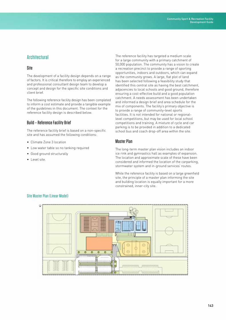
143
Architectural
Site
The development of a facility design depends on a range of factors. It is critical therefore to employ an experienced and professional consultant design team to develop a concept and design for the specific site conditions and client brief.
The following reference facility design has been completed to inform a cost estimate and provide a tangible example of the guidelines in this document. The context for the reference facility design is described below.
Build – Reference Facility Brief
The reference facility brief is based on a non-specific site and has assumed the following conditions:
• Climate Zone 3 location
• Low water table so no tanking required
• Good ground structurally
• Level site.
The reference facility has targeted a medium scale for a large community with a primary catchment of 50,000 population. The community has a vision to create a recreation precinct to provide a range of sporting opportunities, indoors and outdoors, which can expand as the community grows. A large, flat plot of land has been selected following a feasibility study that identified this central site as having the best catchment, adjacencies to local schools and good ground, therefore ensuring a cost-effective build and a good population catchment. A needs assessment has been undertaken and informed a design brief and area schedule for the mix of components. The facility’s primary objective is to provide a range of community-level sports facilities. It is not intended for national or regional-level competitions, but may be used for local school competitions and training. A mixture of cycle and car parking is to be provided in addition to a dedicated school bus and coach drop-off area within the site.
Master Plan
The long-term master plan vision includes an indoor ice rink and gymnastics hall as examples of expansion. The location and approximate scale of these have been considered and informed the location of the carparking, stormwater system and in-ground services’ routes.
While the reference facility is based on a large greenfield site, the principle of a master plan informing the site and building location is equally important for a more constrained, inner-city site.
Site Master Plan (Linear Model)
Community Sport & Recreation Facility Development Guide
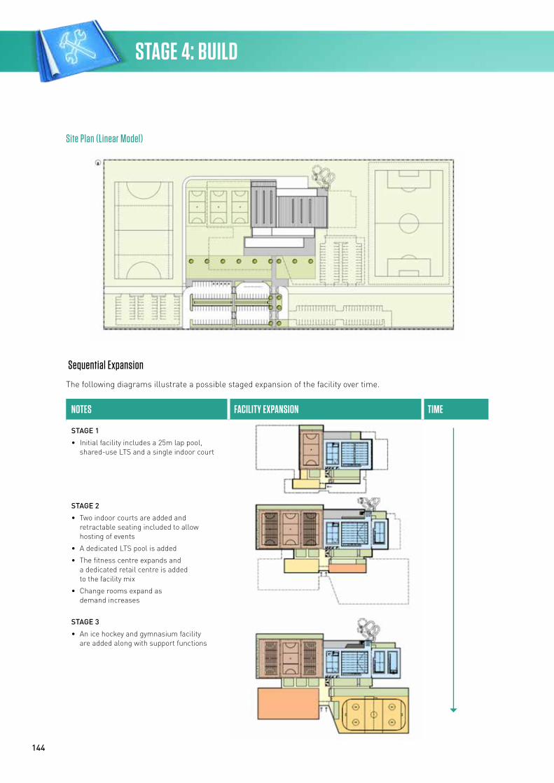
144
Sequential Expansion
The following diagrams illustrate a possible staged expansion of the facility over time.
NOTES FACILITY EXPANSION TIME
STAGE 1
• Initial facility includes a 25m lap pool, shared-use LTS and a single indoor court
STAGE 2
• Two indoor courts are added and retractable seating included to allow hosting of events
• A dedicated LTS pool is added
• The fitness centre expands and a dedicated retail centre is added to the facility mix
• Change rooms expand as demand increases
STAGE 3
• An ice hockey and gymnasium facility are added along with support functions
Site Plan (Linear Model)
STAGE 4: BUILD
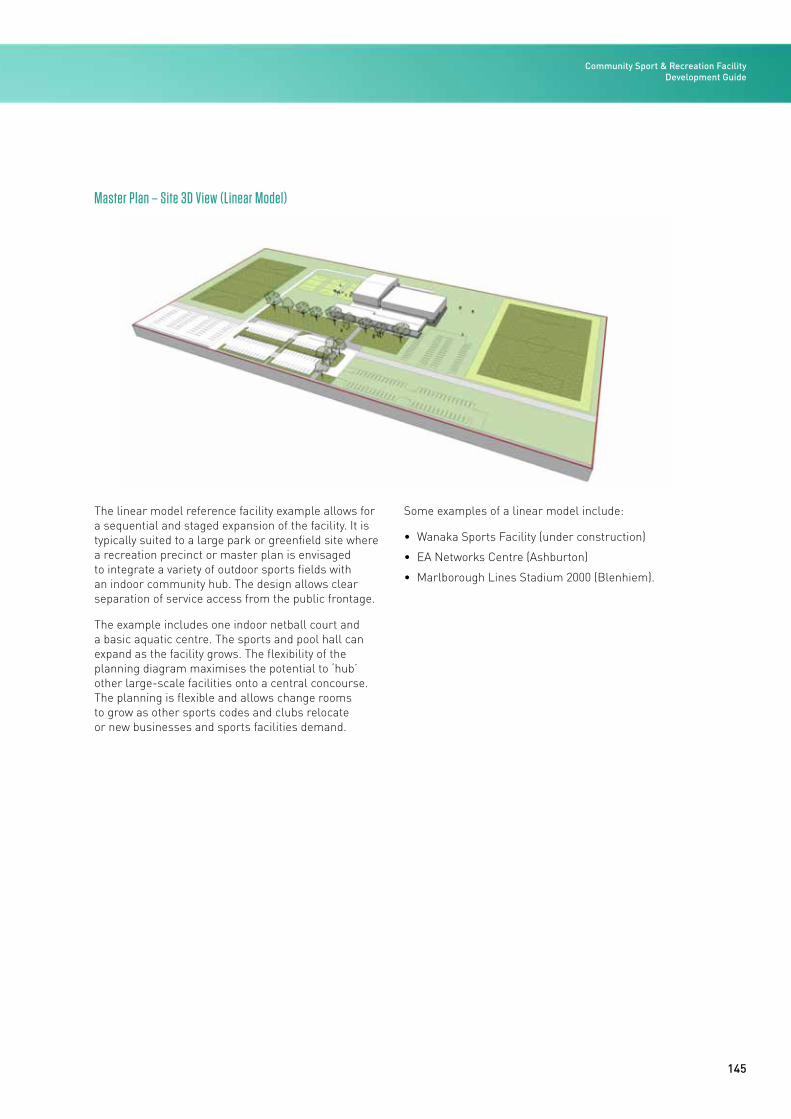
145
The linear model reference facility example allows for a sequential and staged expansion of the facility. It is typically suited to a large park or greenfield site where a recreation precinct or master plan is envisaged to integrate a variety of outdoor sports fields with an indoor community hub. The design allows clear separation of service access from the public frontage.
The example includes one indoor netball court and a basic aquatic centre. The sports and pool hall can expand as the facility grows. The flexibility of the planning diagram maximises the potential to ‘hub’ other large-scale facilities onto a central concourse. The planning is flexible and allows change rooms to grow as other sports codes and clubs relocate or new businesses and sports facilities demand.
Some examples of a linear model include:
• Wanaka Sports Facility (under construction)
• EA Networks Centre (Ashburton)
• Marlborough Lines Stadium 2000 (Blenhiem).
Master Plan – Site 3D View (Linear Model)
Community Sport & Recreation Facility Development Guide
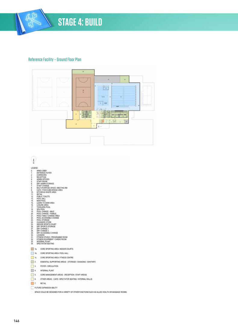
146
Reference Facility – Ground Floor Plan
STAGE 4: BUILD
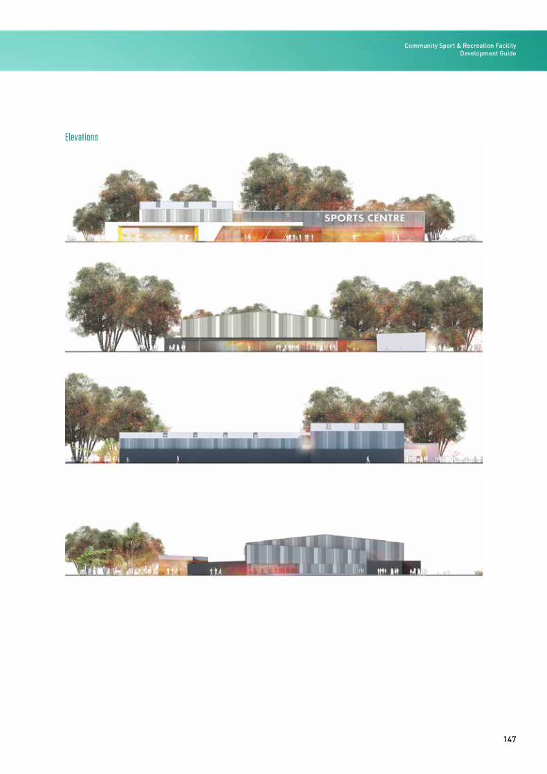
147
Elevations
Community Sport & Recreation Facility Development Guide
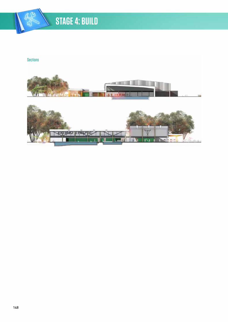
148
Sections
STAGE 4: BUILD
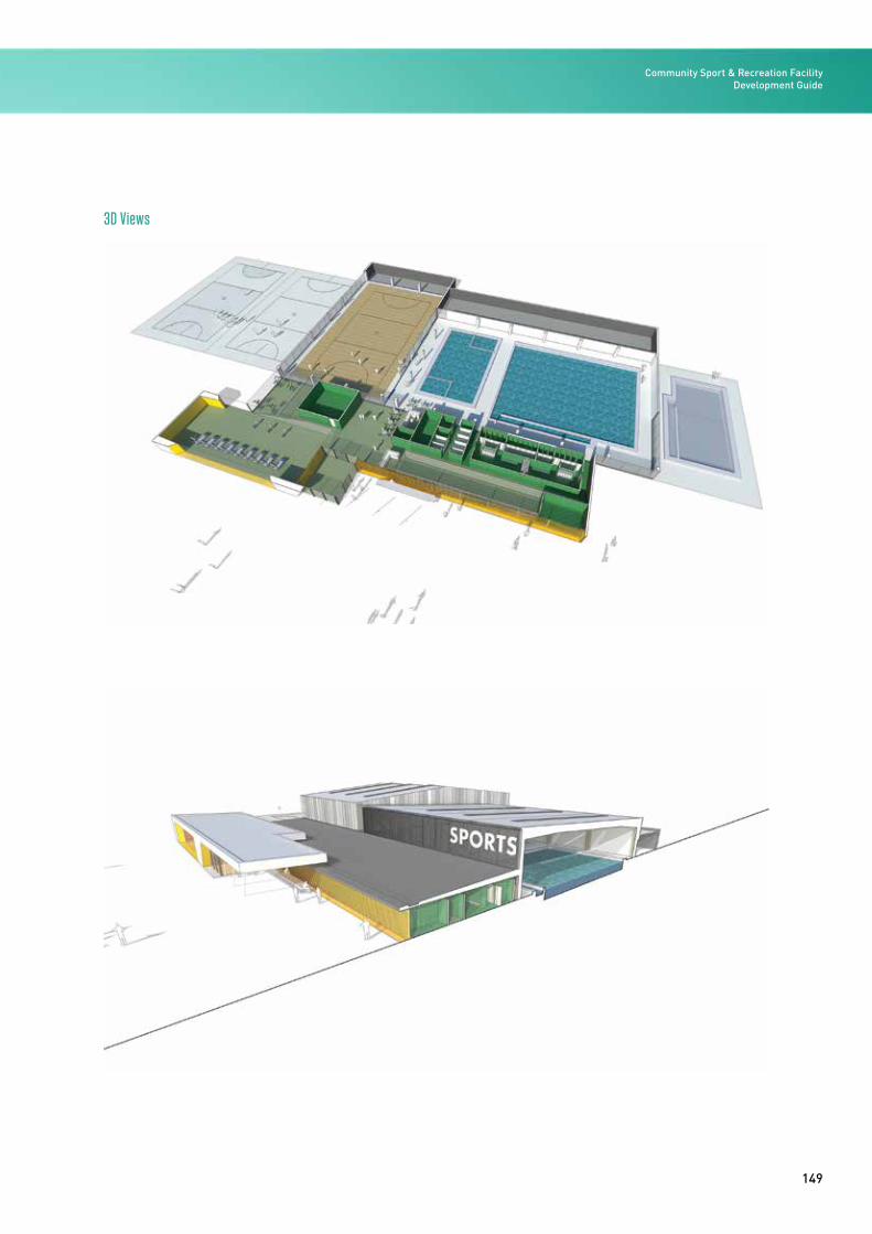
149
3D Views
Community Sport & Recreation Facility Development Guide
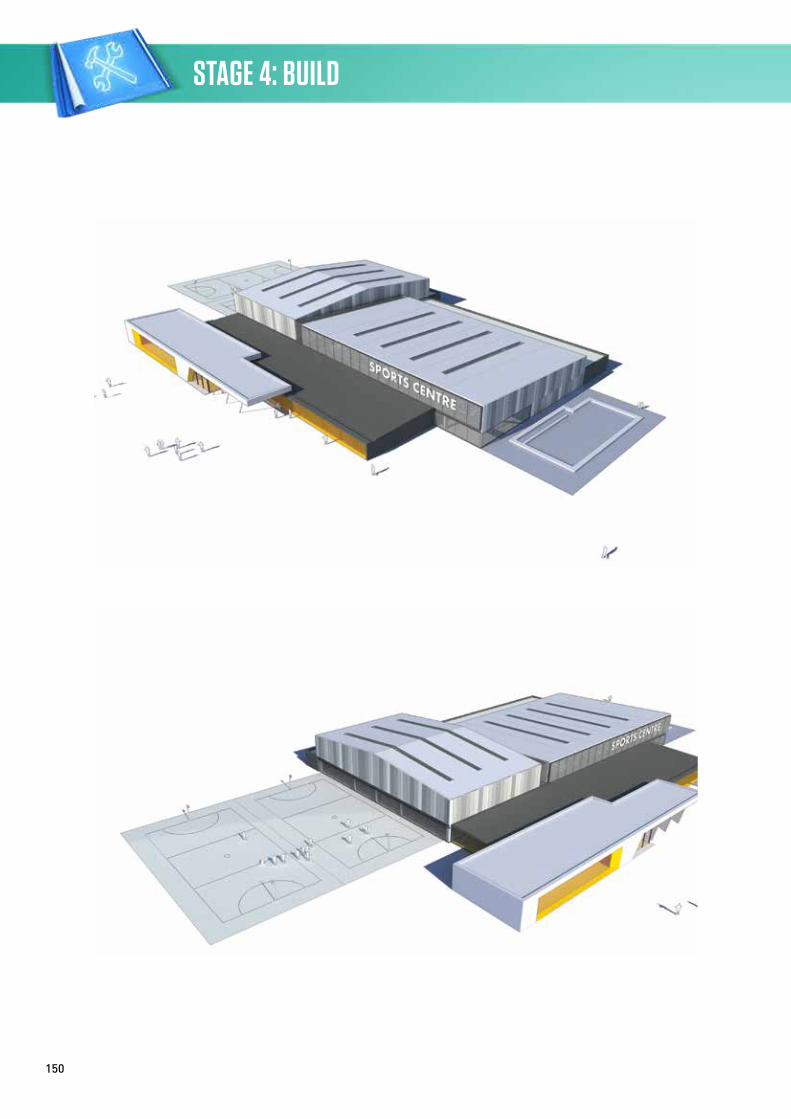
150
STAGE 4: BUILD
151
Design Commentary
The reference facility plan combines all sporting components into a simple single-level building. The core facilities that are included in the reference facility design are discussed below.
The internal layout of the building design has been arranged so that the main entrance elevation and foyer provide a ‘shop window’ to the key facilities within.
Entrance Canopy
An entrance canopy has been provided and sized to provide enough capacity for a school group to wait under cover. The entry and canopy face away from the prevailing wind direction and provide shade during the summer months and under-cover cycle parking.
Entrance, Foyer and Reception
The entrance and reception are designed to give users some viewing of, and direct access to, the internal sports and pool areas. The reception is also the central hub for the operation of the centre, with clear views of external and internal circulation routes. The reception point allows for the observation and management of the adjacent entry turnstile gates, dry change corridors and retail area.
Swimming Pool
The design includes an eight-lane, 25m main pool that is intended to accommodate the following activities:
• LTS – adults
• Teaching shallow dives/race starts
• Use by disabled people
• Leisure (mobile inflatable leisure equipment)
• Fitness swimming
• Aqua jog, aquafit, aquacise, exercise in water
• Water polo and mini water polo
• Underwater hockey
• Canoe/kayak practice
• Lifesaving training
• Sub-aqua training.
A secondary, multi-purpose area provides additional, shallower water to accommodate the following:
• LTS – children
• Leisure (water toys, rope swing, inflatables)
• Dedicated toddlers’ paddling area
• Family spa.
The addition of a secondary pool improves the programme flexibility and income generation potential.
Future expansion has been identified and will include the construction of a dedicated LTS pool.
In-ground pipework and space within the plant room have therefore been provided to allow the additional dedicated LTS pool to be installed in future. The building plan allows for the logical staged expansion of the change rooms as the pool water area increases. Diving demands deep water and is therefore very rarely compatible with community facilities, so diving provision has not been included in the indicative reference facility design. A combination of open-sided and secure lockers is located along the edge of the pool concourse. Pool covers are integrated along the plant and storeroom walls. Limited bench seating is provided around two sides of the main pool and along one side of the leisure and LTS pool.
The pool hall has a height of 5-7m.
Wet Change Space
The wet change rooms have been designed with separate dry and wet entry processes to minimise the migration of dirt to the pool hall. The plan allows the wet change rooms to expand logically in line with pool expansion. Dedicated male, female and family change processes are provided and an oversized accessible change cubicle provided with direct pool access and space to store a wheelchair. Family change cubicles located adjacent to the shallow LTS and leisure beach entry. Five smaller family change cubicles provided, each with a bench and baby change table. A single pool-side toilet is provided in close proximity to the toddlers’ area. Pool-side showers are located close or immediately adjacent to the change exit. Handrails to the main pool ramp separate the deep water from the male and female change rooms exit.
Community Sport & Recreation Facility Development Guide
152
Sports Hall
A single indoor (netball court sized) sports hall (23.4x38.6m) is provided and is sized for one full netball court with the standard 3.05m run-off zones to all sides. A 1m wide circulation zone is provided in addition to the run-off zone to provide for bench seating and buffer space for the structural columns and space for lockers. Additional spectator seating beyond the basic perimeter bench is not considered necessary for this particular small, one-court, community facility.
The structural portal is designed to span the length of the court to allow the hall to expand east to accommodate one or two additional netball courts.
Three courts are considered a good configuration for an event court set-up due to the ability to configure the centre court as the main event court supported by retractable seating from the sides. For this reason, a gable end is proposed on the east façade and the main portal structure spans longitudinally, so that as courts two and three are added to the facility the structural portals can be extended eastwards.
A dry sports equipment store of 12.5 percent of the sports hall floor area is provided along the service side of the building. This provides direct access to the delivery area for flexibility of use when staging events or transporting equipment.
A clear height of 7.5m is provided as the facility is not intending to host international-competition-level netball or volleyball and premier or international-level badminton.
Fitness Centre
A 300m2 health and fitness centre is proposed based on the local market conditions. The fitness area is highly visible from the foyer and glazed externally to activate the external landscape and carpark areas. The ground floor health and fitness area shares the use of the sports hall change rooms. A small, single, multi-purpose studio is located overlooking the indoor sports hall with dual access from the sports hall and from the open-plan fitness area space. Larger group sessions are proposed to be held in the large sports hall. A small instructor’s space with desk and computer is provided inside the open-plan fitness/cardio area. Secure lockers are integrated with the planning of the dry change corridors.
Subject to catchment and local competition factors, a larger health and fitness centre with more stations will attract more ‘members’ and casual users, and improve the financial performance of the centre.
Café
A 60m2 café, sized to reflect the local market conditions, is provided with kitchen, dishwash area, servery and seating areas. The café is highly visible from the entry, sports courts, fitness centre and pool hall. It serves into two distinct seating areas: a dry lounge for non-sporting participants, and a pool-side wet lounge seating area that overlooks the toddlers’ and leisure pool water areas.
Retail
A dedicated retail area is provided adjacent to the main reception. The retail space is highly visible from the foyer and access is from the main circulation spine. The reception staff will provide supervision and point of sale for this space.
Administration
The centre admin block backs onto the main reception space and provides staff support services including open-plan office, staff room, stationery storage, staff change facilities and a shared-use, multi-purpose meeting room. The intention is that the meeting room will be bookable by community groups and therefore act as another potential revenue stream.
Wellness
The admin block could be redesigned to provide wellness and treatment spaces. In this reference facility the multi-purpose meeting room is designed as soft expansion space and may be converted to wellness treatment rooms in future.
Area Schedule
An area schedule is designed to identify the key internal space requirements of the facility. Additional circulation and grossing factors will need to be applied to account for the realities of planning a facility. Typically, the greater the number of components the larger the internal circulation allowances required.
STAGE 4: BUILD
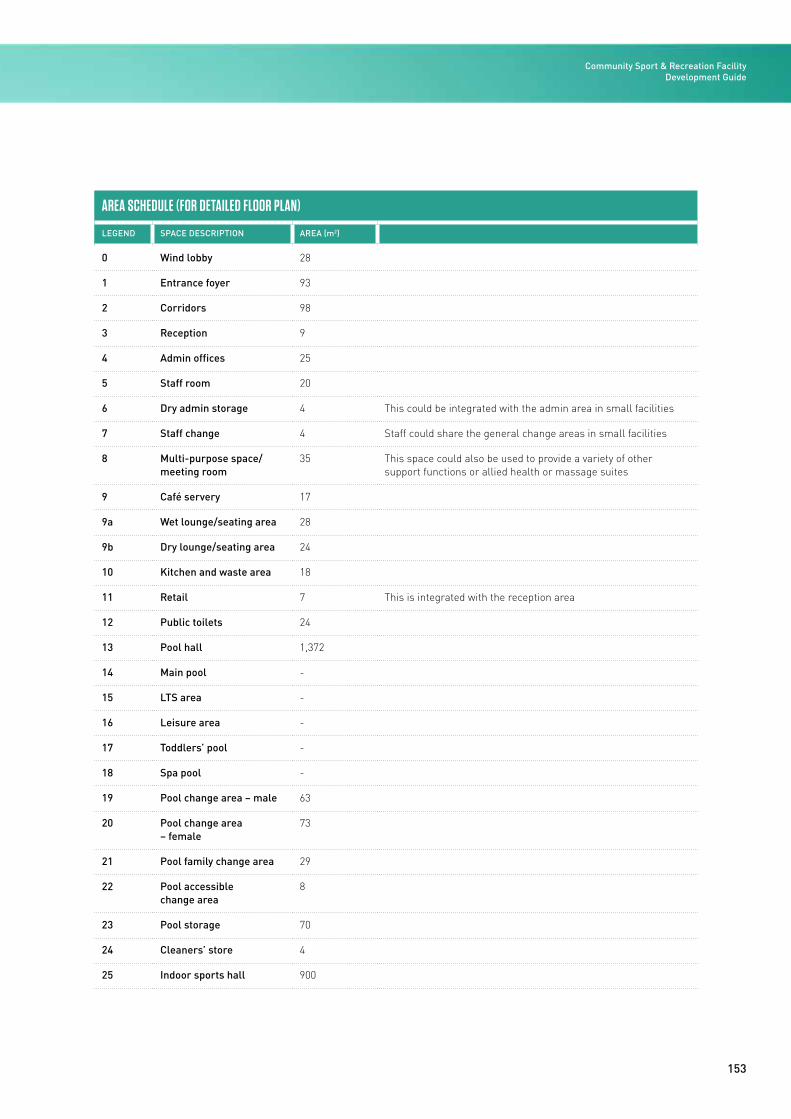
153
AREA SCHEDULE (FOR DETAILED FLOOR PLAN)
LEGEND SPACE DESCRIPTION AREA (m2)
0 Wind lobby 28
1 Entrance foyer 93
2 Corridors 98
3 Reception 9
4 Admin offices 25
5 Staff room 20
6 Dry admin storage 4 This could be integrated with the admin area in small facilities
7 Staff change 4 Staff could share the general change areas in small facilities
8 Multi-purpose space/ meeting room
35 This space could also be used to provide a variety of other support functions or allied health or massage suites
9 Café servery 17
9a Wet lounge/seating area 28
9b Dry lounge/seating area 24
10 Kitchen and waste area 18
11 Retail 7 This is integrated with the reception area
12 Public toilets 24
13 Pool hall 1,372
14 Main pool -
15 LTS area -
16 Leisure area -
17 Toddlers’ pool -
18 Spa pool -
19 Pool change area – male 63
20 Pool change area – female
73
21 Pool family change area 29
22 Pool accessible change area
8
23 Pool storage 70
24 Cleaners’ store 4
25 Indoor sports hall 900
Community Sport & Recreation Facility Development Guide
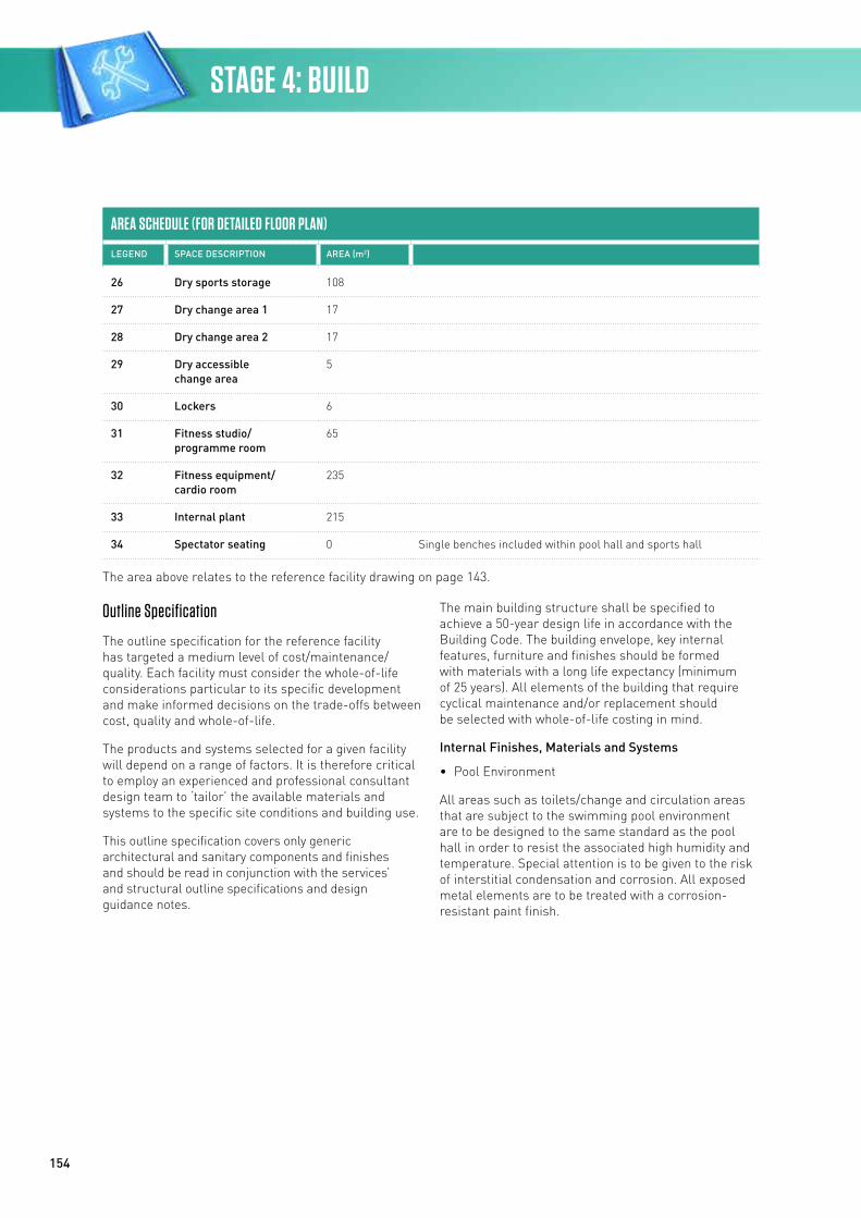
154
AREA SCHEDULE (FOR DETAILED FLOOR PLAN)
LEGEND SPACE DESCRIPTION AREA (m2)
26 Dry sports storage 108
27 Dry change area 1 17
28 Dry change area 2 17
29 Dry accessible change area
5
30 Lockers 6
31 Fitness studio/ programme room
65
32 Fitness equipment/ cardio room
235
33 Internal plant 215
34 Spectator seating 0 Single benches included within pool hall and sports hall
The area above relates to the reference facility drawing on page 143.
Outline Specification
The outline specification for the reference facility has targeted a medium level of cost/maintenance/quality. Each facility must consider the whole-of-life considerations particular to its specific development and make informed decisions on the trade-offs between cost, quality and whole-of-life.
The products and systems selected for a given facility will depend on a range of factors. It is therefore critical to employ an experienced and professional consultant design team to ‘tailor’ the available materials and systems to the specific site conditions and building use.
This outline specification covers only generic architectural and sanitary components and finishes and should be read in conjunction with the services’ and structural outline specifications and design guidance notes.
The main building structure shall be specified to achieve a 50-year design life in accordance with the Building Code. The building envelope, key internal features, furniture and finishes should be formed with materials with a long life expectancy (minimum of 25 years). All elements of the building that require cyclical maintenance and/or replacement should be selected with whole-of-life costing in mind.
Internal Finishes, Materials and Systems
• Pool Environment
All areas such as toilets/change and circulation areas that are subject to the swimming pool environment are to be designed to the same standard as the pool hall in order to resist the associated high humidity and temperature. Special attention is to be given to the risk of interstitial condensation and corrosion. All exposed metal elements are to be treated with a corrosion-resistant paint finish.
STAGE 4: BUILD
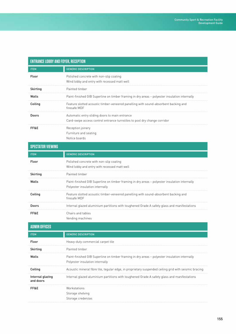
155
ENTRANCE LOBBY AND FOYER, RECEPTION
ITEM GENERIC DESCRIPTION
Floor Polished concrete with non-slip coating
Wind lobby and entry with recessed matt well
Skirting Painted timber
Walls Paint-finished GIB Superline on timber framing in dry areas – polyester insulation internally
Ceiling Feature slotted acoustic timber-veneered panelling with sound-absorbent backing and firesafe MDF
Doors Automatic entry sliding doors to main entrance
Card-swipe access control entrance turnstiles to pool dry change corridor
FF&E Reception joinery
Furniture and seating
Notice boards
SPECTATOR VIEWING
ITEM GENERIC DESCRIPTION
Floor Polished concrete with non-slip coating
Wind lobby and entry with recessed matt well
Skirting Painted timber
Walls Paint-finished GIB Superline on timber framing in dry areas – polyester insulation internally
Polyester insulation internally
Ceiling Feature slotted acoustic timber-veneered panelling with sound-absorbent backing and firesafe MDF
Doors Internal glazed aluminium partitions with toughened Grade A safety glass and manifestations
FF&E Chairs and tables
Vending machines
ADMIN OFFICES
ITEM GENERIC DESCRIPTION
Floor Heavy-duty commercial carpet tile
Skirting Painted timber
Walls Paint-finished GIB Superline on timber framing in dry areas – polyester insulation internally
Polyester insulation internally
Ceiling Acoustic mineral fibre tile, tegular edge, in proprietary suspended ceiling grid with seismic bracing
Internal glazing and doors
Internal glazed aluminium partitions with toughened Grade A safety glass and manifestations
FF&E Workstations
Storage shelving
Storage credenzas
Community Sport & Recreation Facility Development Guide
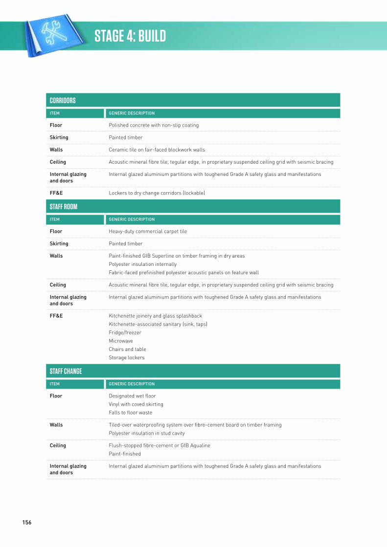
156
CORRIDORS
ITEM GENERIC DESCRIPTION
Floor Polished concrete with non-slip coating
Skirting Painted timber
Walls Ceramic tile on fair-faced blockwork walls
Ceiling Acoustic mineral fibre tile, tegular edge, in proprietary suspended ceiling grid with seismic bracing
Internal glazing and doors
Internal glazed aluminium partitions with toughened Grade A safety glass and manifestations
FF&E Lockers to dry change corridors (lockable)
STAFF ROOM
ITEM GENERIC DESCRIPTION
Floor Heavy-duty commercial carpet tile
Skirting Painted timber
Walls Paint-finished GIB Superline on timber framing in dry areas
Polyester insulation internally
Fabric-faced prefinished polyester acoustic panels on feature wall
Ceiling Acoustic mineral fibre tile, tegular edge, in proprietary suspended ceiling grid with seismic bracing
Internal glazing and doors
Internal glazed aluminium partitions with toughened Grade A safety glass and manifestations
FF&E Kitchenette joinery and glass splashback
Kitchenette-associated sanitary (sink, taps)
Fridge/freezer
Microwave
Chairs and table
Storage lockers
STAFF CHANGE
ITEM GENERIC DESCRIPTION
Floor Designated wet floor
Vinyl with coved skirting
Falls to floor waste
Walls Tiled-over waterproofing system over fibre-cement board on timber framing
Polyester insulation in stud cavity
Ceiling Flush-stopped fibre-cement or GIB Aqualine
Paint-finished
Internal glazing and doors
Internal glazed aluminium partitions with toughened Grade A safety glass and manifestations
STAGE 4: BUILD
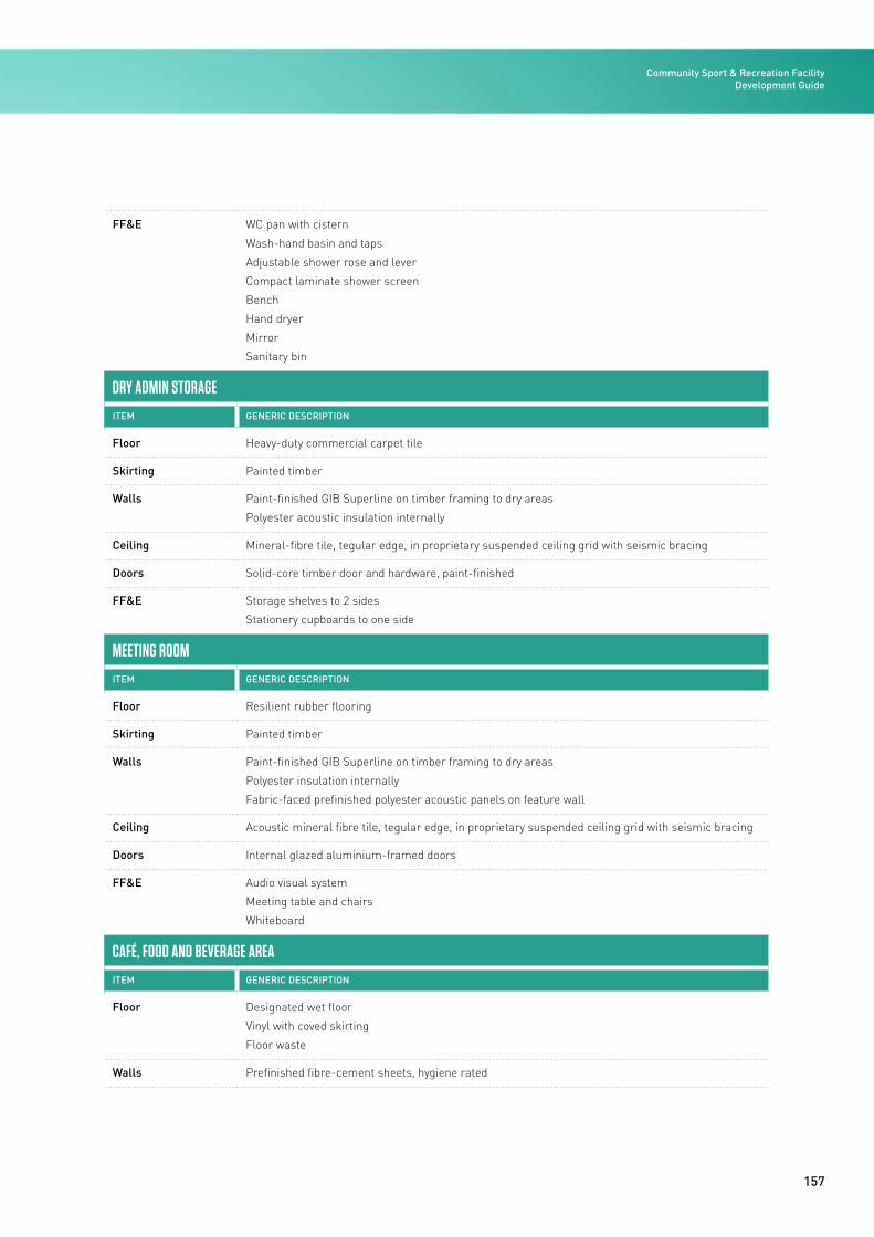
157
FF&E WC pan with cistern
Wash-hand basin and taps
Adjustable shower rose and lever
Compact laminate shower screen
Bench
Hand dryer
Mirror
Sanitary bin
DRY ADMIN STORAGE
ITEM GENERIC DESCRIPTION
Floor Heavy-duty commercial carpet tile
Skirting Painted timber
Walls Paint-finished GIB Superline on timber framing to dry areas
Polyester acoustic insulation internally
Ceiling Mineral-fibre tile, tegular edge, in proprietary suspended ceiling grid with seismic bracing
Doors Solid-core timber door and hardware, paint-finished
FF&E Storage shelves to 2 sides
Stationery cupboards to one side
MEETING ROOM
ITEM GENERIC DESCRIPTION
Floor Resilient rubber flooring
Skirting Painted timber
Walls Paint-finished GIB Superline on timber framing to dry areas
Polyester insulation internally
Fabric-faced prefinished polyester acoustic panels on feature wall
Ceiling Acoustic mineral fibre tile, tegular edge, in proprietary suspended ceiling grid with seismic bracing
Doors Internal glazed aluminium-framed doors
FF&E Audio visual system
Meeting table and chairs
Whiteboard
CAFÉ, FOOD AND BEVERAGE AREA
ITEM GENERIC DESCRIPTION
Floor Designated wet floor
Vinyl with coved skirting
Floor waste
Walls Prefinished fibre-cement sheets, hygiene rated
Community Sport & Recreation Facility Development Guide
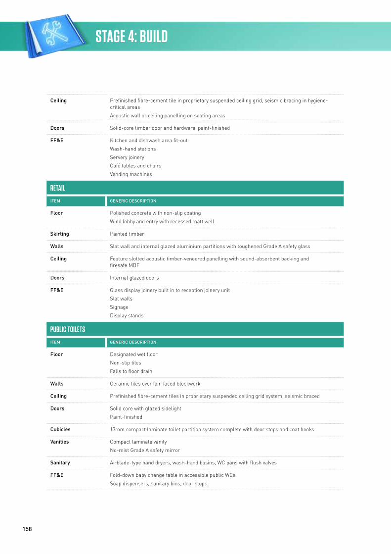
158
Ceiling Prefinished fibre-cement tile in proprietary suspended ceiling grid, seismic bracing in hygiene-critical areas
Acoustic wall or ceiling panelling on seating areas
Doors Solid-core timber door and hardware, paint-finished
FF&E Kitchen and dishwash area fit-out
Wash-hand stations
Servery joinery
Café tables and chairs
Vending machines
RETAIL
ITEM GENERIC DESCRIPTION
Floor Polished concrete with non-slip coating
Wind lobby and entry with recessed matt well
Skirting Painted timber
Walls Slat wall and internal glazed aluminium partitions with toughened Grade A safety glass
Ceiling Feature slotted acoustic timber-veneered panelling with sound-absorbent backing and firesafe MDF
Doors Internal glazed doors
FF&E Glass display joinery built in to reception joinery unit
Slat walls
Signage
Display stands
PUBLIC TOILETS
ITEM GENERIC DESCRIPTION
Floor Designated wet floor
Non-slip tiles
Falls to floor drain
Walls Ceramic tiles over fair-faced blockwork
Ceiling Prefinished fibre-cement tiles in proprietary suspended ceiling grid system, seismic braced
Doors Solid core with glazed sidelight
Paint-finished
Cubicles 13mm compact laminate toilet partition system complete with door stops and coat hooks
Vanities Compact laminate vanity
No-mist Grade A safety mirror
Sanitary Airblade-type hand dryers, wash-hand basins, WC pans with flush valves
FF&E Fold-down baby change table in accessible public WCs
Soap dispensers, sanitary bins, door stops
STAGE 4: BUILD
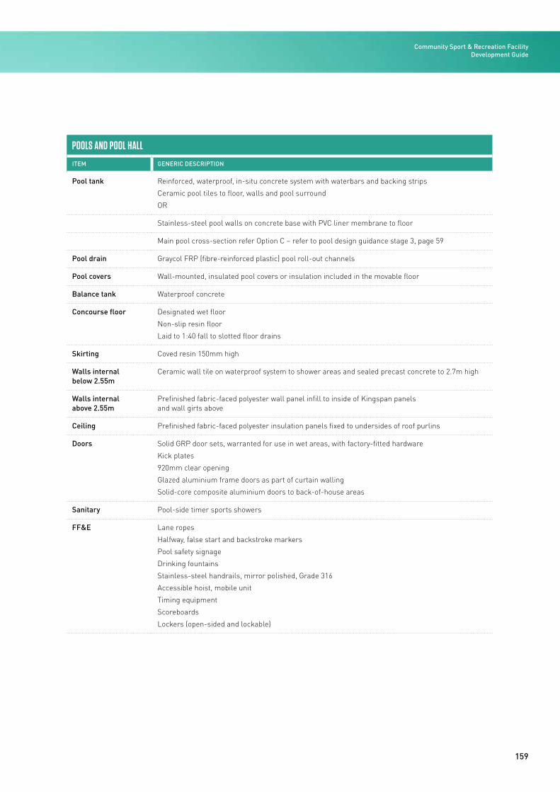
159
POOLS AND POOL HALL
ITEM GENERIC DESCRIPTION
Pool tank Reinforced, waterproof, in-situ concrete system with waterbars and backing strips
Ceramic pool tiles to floor, walls and pool surround
OR
Stainless-steel pool walls on concrete base with PVC liner membrane to floor
Main pool cross-section refer Option C – refer to pool design guidance stage 3, page 59
Pool drain Graycol FRP (fibre-reinforced plastic) pool roll-out channels
Pool covers Wall-mounted, insulated pool covers or insulation included in the movable floor
Balance tank Waterproof concrete
Concourse floor Designated wet floor
Non-slip resin floor
Laid to 1:40 fall to slotted floor drains
Skirting Coved resin 150mm high
Walls internal below 2.55m
Ceramic wall tile on waterproof system to shower areas and sealed precast concrete to 2.7m high
Walls internal above 2.55m
Prefinished fabric-faced polyester wall panel infill to inside of Kingspan panels and wall girts above
Ceiling Prefinished fabric-faced polyester insulation panels fixed to undersides of roof purlins
Doors Solid GRP door sets, warranted for use in wet areas, with factory-fitted hardware
Kick plates
920mm clear opening
Glazed aluminium frame doors as part of curtain walling
Solid-core composite aluminium doors to back-of-house areas
Sanitary Pool-side timer sports showers
FF&E Lane ropes
Halfway, false start and backstroke markers
Pool safety signage
Drinking fountains
Stainless-steel handrails, mirror polished, Grade 316
Accessible hoist, mobile unit
Timing equipment
Scoreboards
Lockers (open-sided and lockable)
Community Sport & Recreation Facility Development Guide
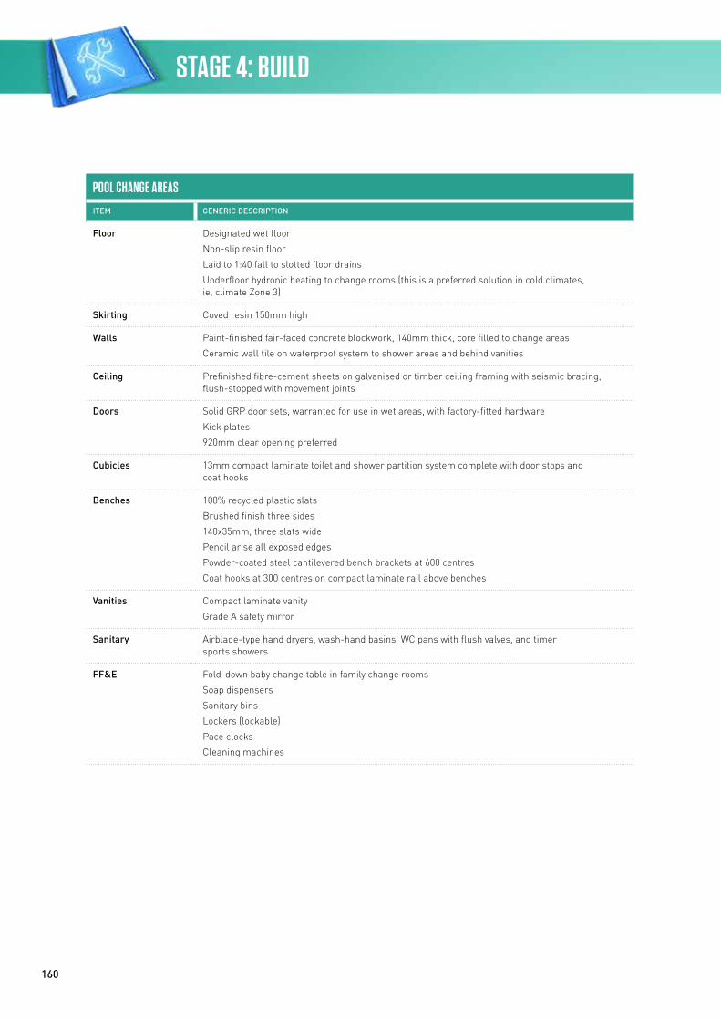
160
POOL CHANGE AREAS
ITEM GENERIC DESCRIPTION
Floor Designated wet floor
Non-slip resin floor
Laid to 1:40 fall to slotted floor drains
Underfloor hydronic heating to change rooms (this is a preferred solution in cold climates, ie, climate Zone 3)
Skirting Coved resin 150mm high
Walls Paint-finished fair-faced concrete blockwork, 140mm thick, core filled to change areas
Ceramic wall tile on waterproof system to shower areas and behind vanities
Ceiling Prefinished fibre-cement sheets on galvanised or timber ceiling framing with seismic bracing, flush-stopped with movement joints
Doors Solid GRP door sets, warranted for use in wet areas, with factory-fitted hardware
Kick plates
920mm clear opening preferred
Cubicles 13mm compact laminate toilet and shower partition system complete with door stops and coat hooks
Benches 100% recycled plastic slats
Brushed finish three sides
140x35mm, three slats wide
Pencil arise all exposed edges
Powder-coated steel cantilevered bench brackets at 600 centres
Coat hooks at 300 centres on compact laminate rail above benches
Vanities Compact laminate vanity
Grade A safety mirror
Sanitary Airblade-type hand dryers, wash-hand basins, WC pans with flush valves, and timer sports showers
FF&E Fold-down baby change table in family change rooms
Soap dispensers
Sanitary bins
Lockers (lockable)
Pace clocks
Cleaning machines
STAGE 4: BUILD
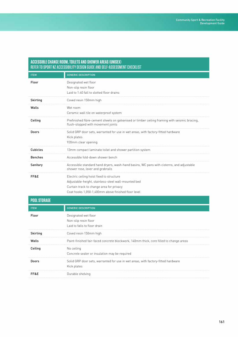
161
ACCESSIBLE CHANGE ROOM, TOILETS AND SHOWER AREAS (UNISEX)REFER TO SPORT NZ ACCESSIBILITY DESIGN GUIDE AND SELF-ASSESSMENT CHECKLIST
ITEM GENERIC DESCRIPTION
Floor Designated wet floor
Non-slip resin floor
Laid to 1:40 fall to slotted floor drains
Skirting Coved resin 150mm high
Walls Wet room
Ceramic wall tile on waterproof system
Ceiling Prefinished fibre-cement sheets on galvanised or timber ceiling framing with seismic bracing, flush-stopped with movement joints
Doors Solid GRP door sets, warranted for use in wet areas, with factory-fitted hardware
Kick plates
920mm clear opening
Cubicles 13mm compact laminate toilet and shower partition system
Benches Accessible fold-down shower bench
Sanitary Accessible standard hand dryers, wash-hand basins, WC pans with cisterns, and adjustable shower rose, lever and grabrails
FF&E Electric ceiling hoist fixed to structure
Adjustable-height, stainless-steel wall-mounted bed
Curtain track to change area for privacy
Coat hooks 1,050-1,400mm above finished floor level
POOL STORAGE
ITEM GENERIC DESCRIPTION
Floor Designated wet floor
Non-slip resin floor
Laid to falls to floor drain
Skirting Coved resin 150mm high
Walls Paint-finished fair-faced concrete blockwork, 140mm thick, core filled to change areas
Ceiling No ceiling
Concrete sealer or insulation may be required
Doors Solid GRP door sets, warranted for use in wet areas, with factory-fitted hardware
Kick plates
FF&E Durable shelving
Community Sport & Recreation Facility Development Guide
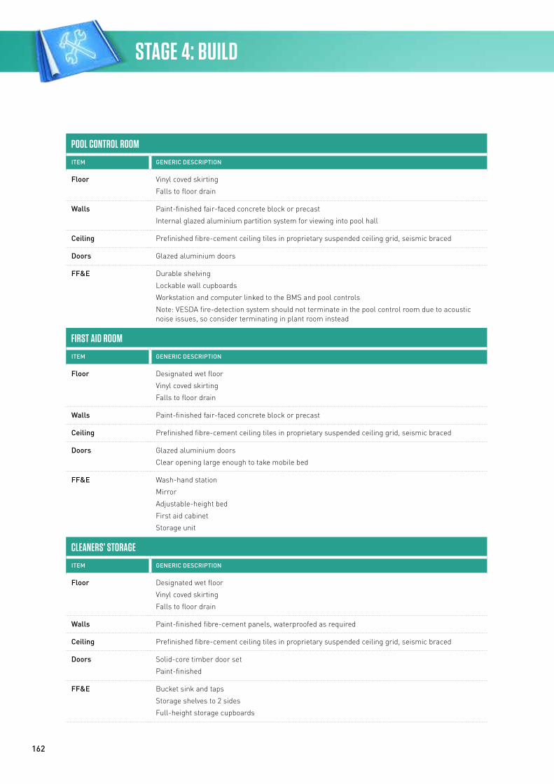
162
POOL CONTROL ROOM
ITEM GENERIC DESCRIPTION
Floor Vinyl coved skirting
Falls to floor drain
Walls Paint-finished fair-faced concrete block or precast
Internal glazed aluminium partition system for viewing into pool hall
Ceiling Prefinished fibre-cement ceiling tiles in proprietary suspended ceiling grid, seismic braced
Doors Glazed aluminium doors
FF&E Durable shelving
Lockable wall cupboards
Workstation and computer linked to the BMS and pool controls
Note: VESDA fire-detection system should not terminate in the pool control room due to acoustic noise issues, so consider terminating in plant room instead
FIRST AID ROOM
ITEM GENERIC DESCRIPTION
Floor Designated wet floor
Vinyl coved skirting
Falls to floor drain
Walls Paint-finished fair-faced concrete block or precast
Ceiling Prefinished fibre-cement ceiling tiles in proprietary suspended ceiling grid, seismic braced
Doors Glazed aluminium doors
Clear opening large enough to take mobile bed
FF&E Wash-hand station
Mirror
Adjustable-height bed
First aid cabinet
Storage unit
CLEANERS’ STORAGE
ITEM GENERIC DESCRIPTION
Floor Designated wet floor
Vinyl coved skirting
Falls to floor drain
Walls Paint-finished fibre-cement panels, waterproofed as required
Ceiling Prefinished fibre-cement ceiling tiles in proprietary suspended ceiling grid, seismic braced
Doors Solid-core timber door set
Paint-finished
FF&E Bucket sink and taps
Storage shelves to 2 sides
Full-height storage cupboards
STAGE 4: BUILD
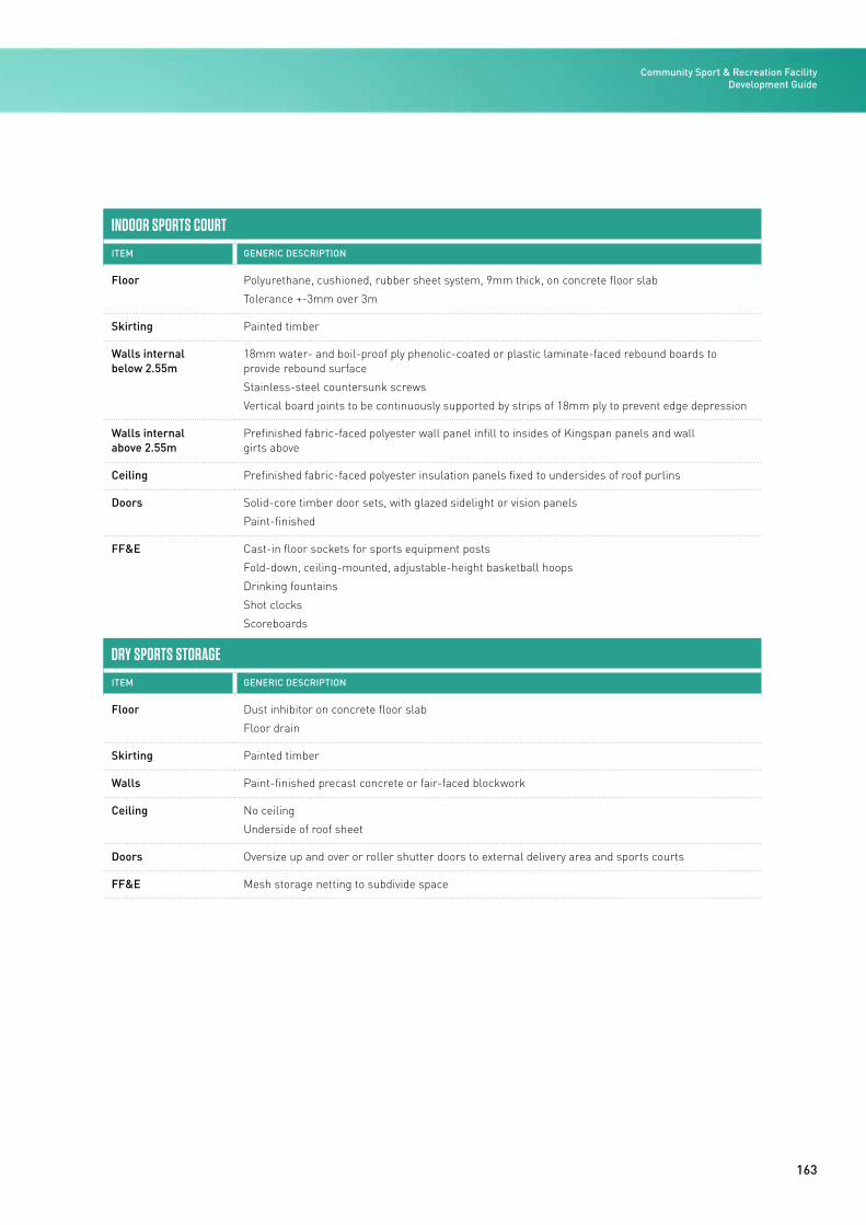
163
INDOOR SPORTS COURT
ITEM GENERIC DESCRIPTION
Floor Polyurethane, cushioned, rubber sheet system, 9mm thick, on concrete floor slab
Tolerance +-3mm over 3m
Skirting Painted timber
Walls internal below 2.55m
18mm water- and boil-proof ply phenolic-coated or plastic laminate-faced rebound boards to provide rebound surface
Stainless-steel countersunk screws
Vertical board joints to be continuously supported by strips of 18mm ply to prevent edge depression
Walls internal above 2.55m
Prefinished fabric-faced polyester wall panel infill to insides of Kingspan panels and wall girts above
Ceiling Prefinished fabric-faced polyester insulation panels fixed to undersides of roof purlins
Doors Solid-core timber door sets, with glazed sidelight or vision panels
Paint-finished
FF&E Cast-in floor sockets for sports equipment posts
Fold-down, ceiling-mounted, adjustable-height basketball hoops
Drinking fountains
Shot clocks
Scoreboards
DRY SPORTS STORAGE
ITEM GENERIC DESCRIPTION
Floor Dust inhibitor on concrete floor slab
Floor drain
Skirting Painted timber
Walls Paint-finished precast concrete or fair-faced blockwork
Ceiling No ceiling
Underside of roof sheet
Doors Oversize up and over or roller shutter doors to external delivery area and sports courts
FF&E Mesh storage netting to subdivide space
Community Sport & Recreation Facility Development Guide
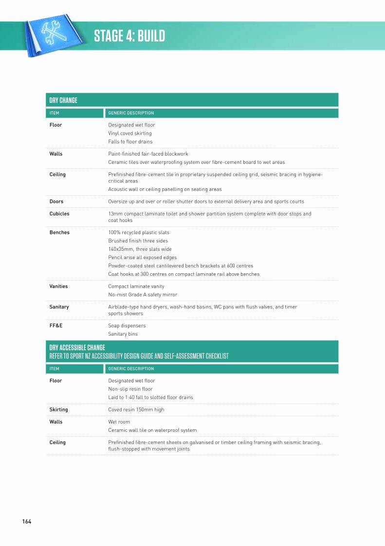
164
DRY CHANGE
ITEM GENERIC DESCRIPTION
Floor Designated wet floor
Vinyl coved skirting
Falls to floor drains
Walls Paint-finished fair-faced blockwork
Ceramic tiles over waterproofing system over fibre-cement board to wet areas
Ceiling Prefinished fibre-cement tile in proprietary suspended ceiling grid, seismic bracing in hygiene-critical areas
Acoustic wall or ceiling panelling on seating areas
Doors Oversize up and over or roller shutter doors to external delivery area and sports courts
Cubicles 13mm compact laminate toilet and shower partition system complete with door stops and coat hooks
Benches 100% recycled plastic slats
Brushed finish three sides
140x35mm, three slats wide
Pencil arise all exposed edges
Powder-coated steel cantilevered bench brackets at 600 centres
Coat hooks at 300 centres on compact laminate rail above benches
Vanities Compact laminate vanity
No-mist Grade A safety mirror
Sanitary Airblade-type hand dryers, wash-hand basins, WC pans with flush valves, and timer sports showers
FF&E Soap dispensers
Sanitary bins
DRY ACCESSIBLE CHANGEREFER TO SPORT NZ ACCESSIBILITY DESIGN GUIDE AND SELF-ASSESSMENT CHECKLIST
ITEM GENERIC DESCRIPTION
Floor Designated wet floor
Non-slip resin floor
Laid to 1:40 fall to slotted floor drains
Skirting Coved resin 150mm high
Walls Wet room
Ceramic wall tile on waterproof system
Ceiling Prefinished fibre-cement sheets on galvanised or timber ceiling framing with seismic bracing, flush-stopped with movement joints
STAGE 4: BUILD
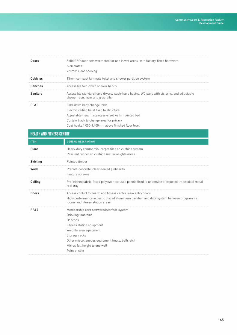
165
Doors Solid GRP door sets warranted for use in wet areas, with factory-fitted hardware
Kick plates
920mm clear opening
Cubicles 13mm compact laminate toilet and shower partition system
Benches Accessible fold-down shower bench
Sanitary Accessible standard hand dryers, wash-hand basins, WC pans with cisterns, and adjustable shower rose, lever and grabrails
FF&E Fold-down baby change table
Electric ceiling hoist fixed to structure
Adjustable-height, stainless-steel wall-mounted bed
Curtain track to change area for privacy
Coat hooks 1,050-1,400mm above finished floor level
HEALTH AND FITNESS CENTRE
ITEM GENERIC DESCRIPTION
Floor Heavy-duty commercial carpet tiles on cushion system
Resilient rubber on cushion mat in weights areas
Skirting Painted timber
Walls Precast-concrete, clear-sealed pinboards
Feature screens
Ceiling Prefinished fabric-faced polyester acoustic panels fixed to underside of exposed trapezoidal metal roof tray
Doors Access control to health and fitness centre main entry doors
High-performance acoustic glazed aluminium partition and door system between programme rooms and fitness station areas
FF&E Membership card software/interface system
Drinking fountains
Benches
Fitness station equipment
Weights area equipment
Storage racks
Other miscellaneous equipment (mats, balls etc)
Mirror, full height to one wall
Point of sale
Community Sport & Recreation Facility Development Guide
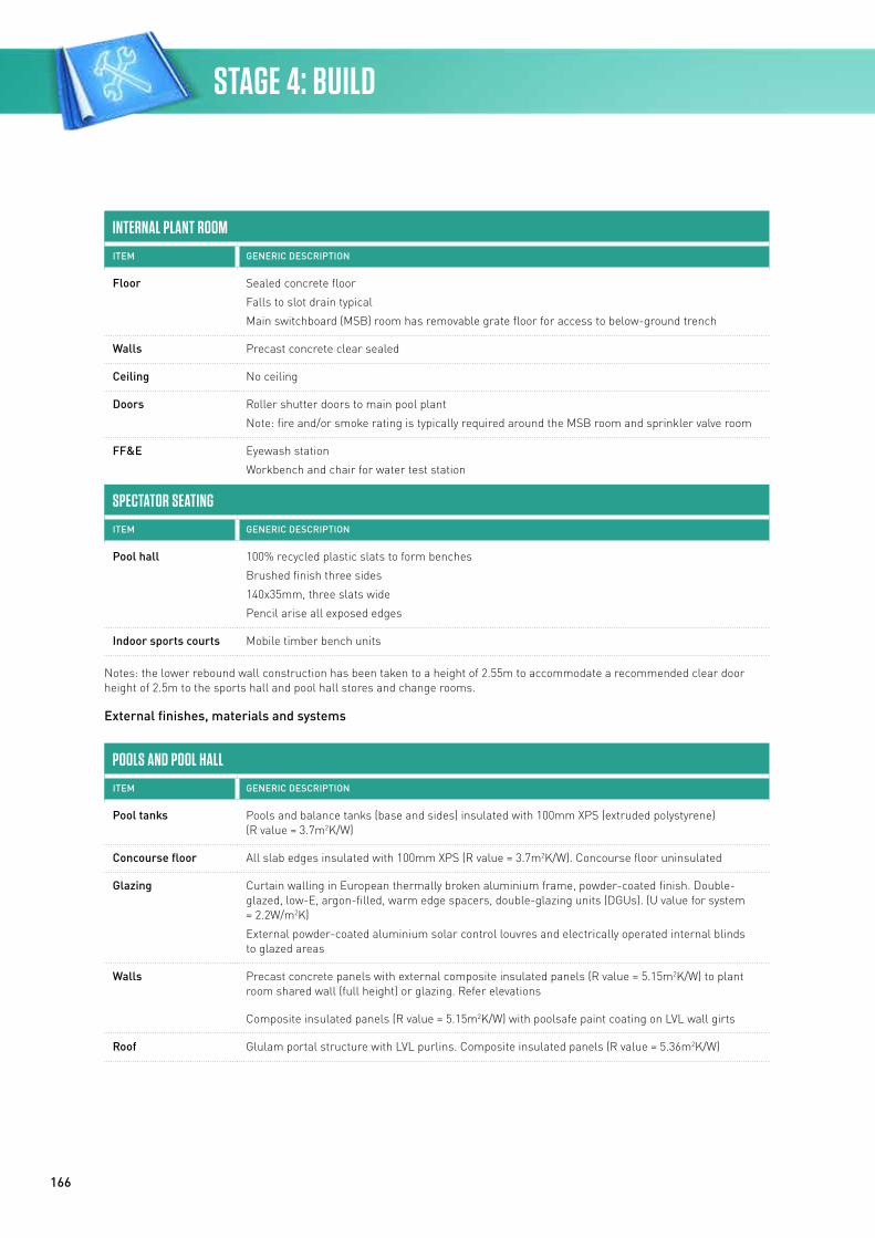
166
INTERNAL PLANT ROOM
ITEM GENERIC DESCRIPTION
Floor Sealed concrete floor
Falls to slot drain typical
Main switchboard (MSB) room has removable grate floor for access to below-ground trench
Walls Precast concrete clear sealed
Ceiling No ceiling
Doors Roller shutter doors to main pool plant
Note: fire and/or smoke rating is typically required around the MSB room and sprinkler valve room
FF&E Eyewash station
Workbench and chair for water test station
SPECTATOR SEATING
ITEM GENERIC DESCRIPTION
Pool hall 100% recycled plastic slats to form benches
Brushed finish three sides
140x35mm, three slats wide
Pencil arise all exposed edges
Indoor sports courts Mobile timber bench units
Notes: the lower rebound wall construction has been taken to a height of 2.55m to accommodate a recommended clear door height of 2.5m to the sports hall and pool hall stores and change rooms.
External finishes, materials and systems
POOLS AND POOL HALL
ITEM GENERIC DESCRIPTION
Pool tanks Pools and balance tanks (base and sides) insulated with 100mm XPS (extruded polystyrene) (R value = 3.7m2K/W)
Concourse floor All slab edges insulated with 100mm XPS (R value = 3.7m2K/W). Concourse floor uninsulated
Glazing Curtain walling in European thermally broken aluminium frame, powder-coated finish. Double-glazed, low-E, argon-filled, warm edge spacers, double-glazing units (DGUs). (U value for system = 2.2W/m2K)
External powder-coated aluminium solar control louvres and electrically operated internal blinds to glazed areas
Walls Precast concrete panels with external composite insulated panels (R value = 5.15m2K/W) to plant room shared wall (full height) or glazing. Refer elevations
Composite insulated panels (R value = 5.15m2K/W) with poolsafe paint coating on LVL wall girts
Roof Glulam portal structure with LVL purlins. Composite insulated panels (R value = 5.36m2K/W)
STAGE 4: BUILD
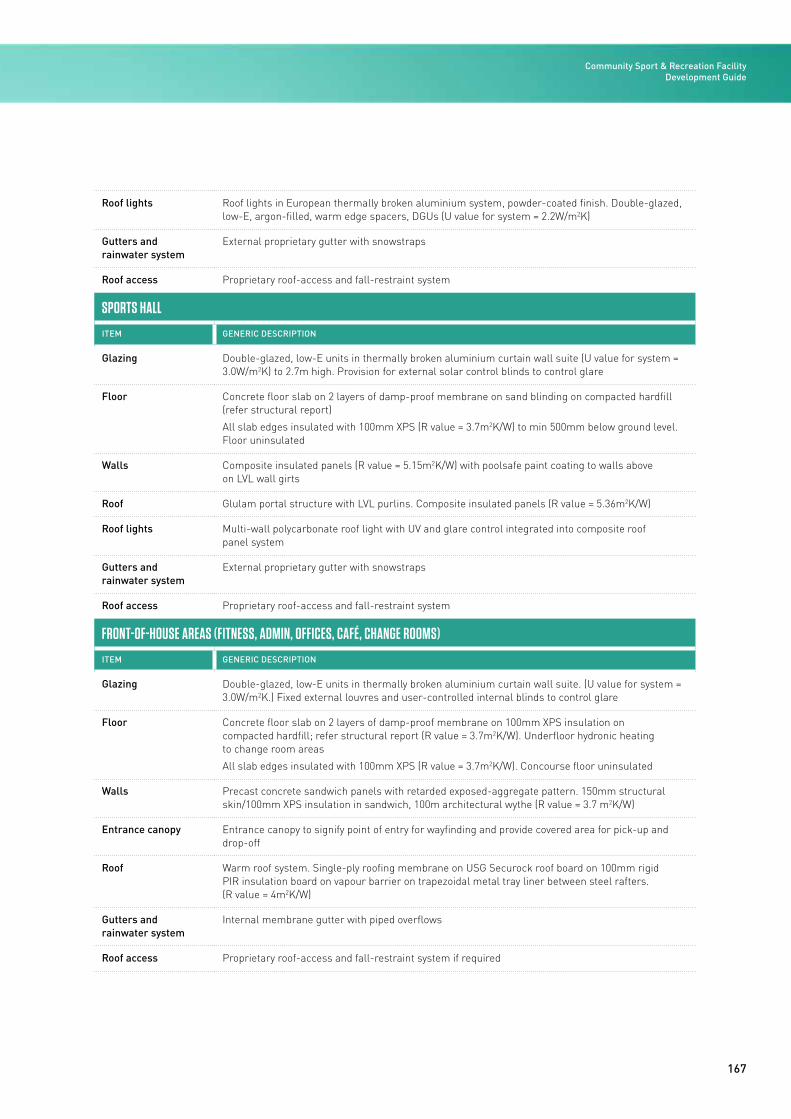
167
Roof lights Roof lights in European thermally broken aluminium system, powder-coated finish. Double-glazed, low-E, argon-filled, warm edge spacers, DGUs (U value for system = 2.2W/m2K)
Gutters and rainwater system
External proprietary gutter with snowstraps
Roof access Proprietary roof-access and fall-restraint system
SPORTS HALL
ITEM GENERIC DESCRIPTION
Glazing Double-glazed, low-E units in thermally broken aluminium curtain wall suite (U value for system = 3.0W/m2K) to 2.7m high. Provision for external solar control blinds to control glare
Floor Concrete floor slab on 2 layers of damp-proof membrane on sand blinding on compacted hardfill (refer structural report)
All slab edges insulated with 100mm XPS (R value = 3.7m2K/W) to min 500mm below ground level. Floor uninsulated
Walls Composite insulated panels (R value = 5.15m2K/W) with poolsafe paint coating to walls above on LVL wall girts
Roof Glulam portal structure with LVL purlins. Composite insulated panels (R value = 5.36m2K/W)
Roof lights Multi-wall polycarbonate roof light with UV and glare control integrated into composite roof panel system
Gutters and rainwater system
External proprietary gutter with snowstraps
Roof access Proprietary roof-access and fall-restraint system
FRONT-OF-HOUSE AREAS (FITNESS, ADMIN, OFFICES, CAFÉ, CHANGE ROOMS)
ITEM GENERIC DESCRIPTION
Glazing Double-glazed, low-E units in thermally broken aluminium curtain wall suite. (U value for system = 3.0W/m2K.) Fixed external louvres and user-controlled internal blinds to control glare
Floor Concrete floor slab on 2 layers of damp-proof membrane on 100mm XPS insulation on compacted hardfill; refer structural report (R value = 3.7m2K/W). Underfloor hydronic heating to change room areas
All slab edges insulated with 100mm XPS (R value = 3.7m2K/W). Concourse floor uninsulated
Walls Precast concrete sandwich panels with retarded exposed-aggregate pattern. 150mm structural skin/100mm XPS insulation in sandwich, 100m architectural wythe (R value = 3.7 m2K/W)
Entrance canopy Entrance canopy to signify point of entry for wayfinding and provide covered area for pick-up and drop-off
Roof Warm roof system. Single-ply roofing membrane on USG Securock roof board on 100mm rigid PIR insulation board on vapour barrier on trapezoidal metal tray liner between steel rafters. (R value = 4m2K/W)
Gutters and rainwater system
Internal membrane gutter with piped overflows
Roof access Proprietary roof-access and fall-restraint system if required
Community Sport & Recreation Facility Development Guide
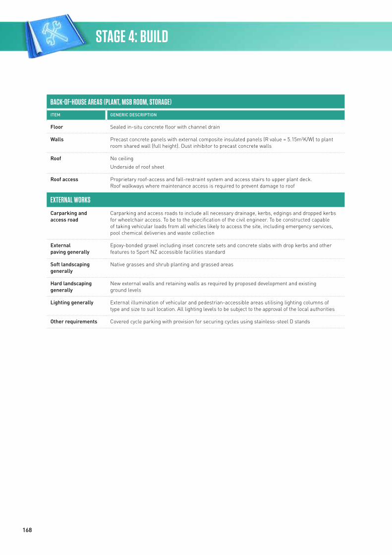
168
BACK-OF-HOUSE AREAS (PLANT, MSB ROOM, STORAGE)
ITEM GENERIC DESCRIPTION
Floor Sealed in-situ concrete floor with channel drain
Walls Precast concrete panels with external composite insulated panels (R value = 5.15m2K/W) to plant room shared wall (full height). Dust inhibitor to precast concrete walls
Roof No ceiling
Underside of roof sheet
Roof access Proprietary roof-access and fall-restraint system and access stairs to upper plant deck. Roof walkways where maintenance access is required to prevent damage to roof
EXTERNAL WORKS
Carparking and access road
Carparking and access roads to include all necessary drainage, kerbs, edgings and dropped kerbs for wheelchair access. To be to the specification of the civil engineer. To be constructed capable of taking vehicular loads from all vehicles likely to access the site, including emergency services, pool chemical deliveries and waste collection
External paving generally
Epoxy-bonded gravel including inset concrete sets and concrete slabs with drop kerbs and other features to Sport NZ accessible facilities standard
Soft landscaping generally
Native grasses and shrub planting and grassed areas
Hard landscaping generally
New external walls and retaining walls as required by proposed development and existing ground levels
Lighting generally External illumination of vehicular and pedestrian-accessible areas utilising lighting columns of type and size to suit location. All lighting levels to be subject to the approval of the local authorities
Other requirements Covered cycle parking with provision for securing cycles using stainless-steel D stands
STAGE 4: BUILD
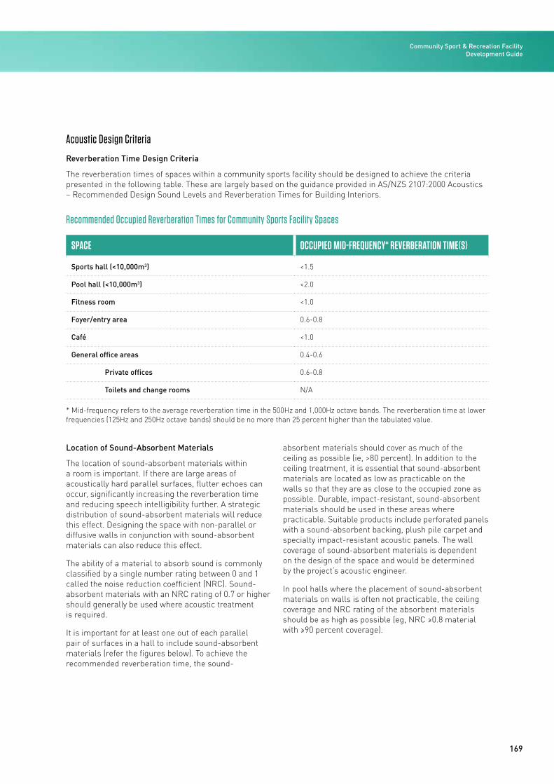
169
Acoustic Design Criteria
Reverberation Time Design Criteria
The reverberation times of spaces within a community sports facility should be designed to achieve the criteria presented in the following table. These are largely based on the guidance provided in AS/NZS 2107:2000 Acoustics – Recommended Design Sound Levels and Reverberation Times for Building Interiors.
Recommended Occupied Reverberation Times for Community Sports Facility Spaces
SPACE OCCUPIED MID-FREQUENCY* REVERBERATION TIME(S)
Sports hall (<10,000m3) <1.5
Pool hall (<10,000m3) <2.0
Fitness room <1.0
Foyer/entry area 0.6-0.8
Café <1.0
General office areas 0.4-0.6
Private offices 0.6-0.8
Toilets and change rooms N/A
* Mid-frequency refers to the average reverberation time in the 500Hz and 1,000Hz octave bands. The reverberation time at lower frequencies (125Hz and 250Hz octave bands) should be no more than 25 percent higher than the tabulated value.
Location of Sound-Absorbent Materials
The location of sound-absorbent materials within a room is important. If there are large areas of acoustically hard parallel surfaces, flutter echoes can occur, significantly increasing the reverberation time and reducing speech intelligibility further. A strategic distribution of sound-absorbent materials will reduce this effect. Designing the space with non-parallel or diffusive walls in conjunction with sound-absorbent materials can also reduce this effect.
The ability of a material to absorb sound is commonly classified by a single number rating between 0 and 1 called the noise reduction coefficient (NRC). Sound-absorbent materials with an NRC rating of 0.7 or higher should generally be used where acoustic treatment is required.
It is important for at least one out of each parallel pair of surfaces in a hall to include sound-absorbent materials (refer the figures below). To achieve the recommended reverberation time, the sound-
absorbent materials should cover as much of the ceiling as possible (ie, >80 percent). In addition to the ceiling treatment, it is essential that sound-absorbent materials are located as low as practicable on the walls so that they are as close to the occupied zone as possible. Durable, impact-resistant, sound-absorbent materials should be used in these areas where practicable. Suitable products include perforated panels with a sound-absorbent backing, plush pile carpet and specialty impact-resistant acoustic panels. The wall coverage of sound-absorbent materials is dependent on the design of the space and would be determined by the project’s acoustic engineer.
In pool halls where the placement of sound-absorbent materials on walls is often not practicable, the ceiling coverage and NRC rating of the absorbent materials should be as high as possible (eg, NRC ≥0.8 material with ≥90 percent coverage).
Community Sport & Recreation Facility Development Guide
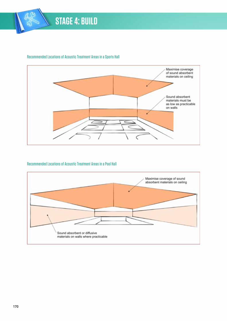
170
Recommended Locations of Acoustic Treatment Areas in a Sports Hall
Recommended Locations of Acoustic Treatment Areas in a Pool Hall
STAGE 4: BUILD
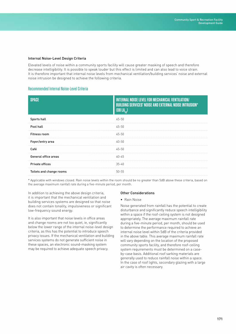
171
Internal Noise-Level Design Criteria
Elevated levels of noise within a community sports facility will cause greater masking of speech and therefore decrease intelligibility. It is possible to speak louder but this effect is limited and can also lead to voice strain. It is therefore important that internal noise levels from mechanical ventilation/building services’ noise and external noise intrusion be designed to achieve the following criteria.
Recommended Internal Noise-Level Criteria
SPACE INTERNAL NOISE LEVEL FOR MECHANICAL VENTILATION/ BUILDING SERVICES’ NOISE AND EXTERNAL NOISE INTRUSION*(DB LA
EQ)
Sports hall 45-50
Pool hall 45-50
Fitness room 45-50
Foyer/entry area 40-50
Café 45-50
General office areas 40-45
Private offices 35-40
Toilets and change rooms 50-55
* Applicable with windows closed. Rain noise levels within the room should be no greater than 5dB above these criteria, based on the average maximum rainfall rate during a five-minute period, per month.
In addition to achieving the above design criteria, it is important that the mechanical ventilation and building services systems are designed so that noise does not contain tonality, impulsiveness or significant low-frequency sound energy.
It is also important that noise levels in office areas and change rooms are not too quiet, ie, significantly below the lower range of the internal noise-level design criteria, as this has the potential to introduce speech privacy issues. If the mechanical ventilation and building services systems do not generate sufficient noise in these spaces, an electronic sound-masking system may be required to achieve adequate speech privacy.
Other Considerations
• Rain Noise
Noise generated from rainfall has the potential to create disturbance and significantly reduce speech intelligibility within a space if the roof-ceiling system is not designed appropriately. The average maximum rainfall rate during a five-minute period, per month, should be used to determine the performance required to achieve an internal noise level within 5dB of the criteria provided in the above table. This average maximum rainfall rate will vary depending on the location of the proposed community sports facility, and therefore roof-ceiling system requirements must be determined on a case-by-case basis. Additional roof sarking materials are generally used to reduce rainfall noise within a space. In the case of roof lights, secondary glazing with a large air cavity is often necessary.
Community Sport & Recreation Facility Development Guide
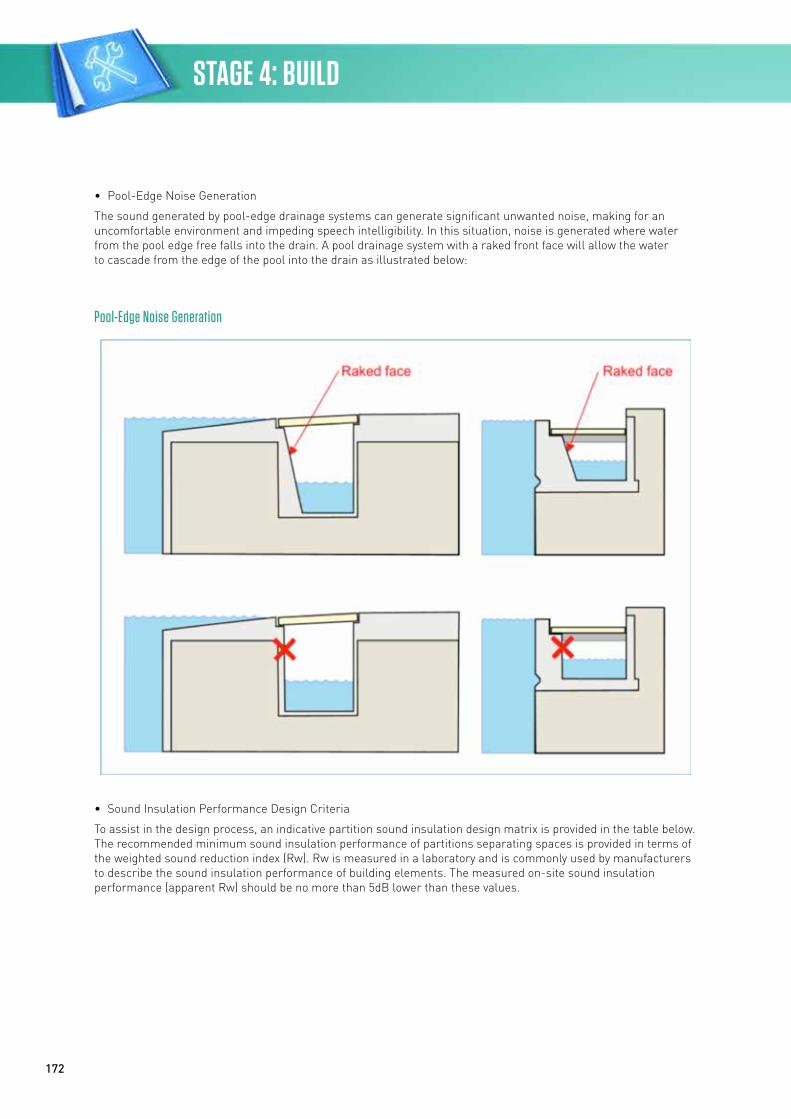
172
Pool-Edge Noise Generation
• Pool-Edge Noise Generation
The sound generated by pool-edge drainage systems can generate significant unwanted noise, making for an uncomfortable environment and impeding speech intelligibility. In this situation, noise is generated where water from the pool edge free falls into the drain. A pool drainage system with a raked front face will allow the water to cascade from the edge of the pool into the drain as illustrated below:
• Sound Insulation Performance Design Criteria
To assist in the design process, an indicative partition sound insulation design matrix is provided in the table below. The recommended minimum sound insulation performance of partitions separating spaces is provided in terms of the weighted sound reduction index (Rw). Rw is measured in a laboratory and is commonly used by manufacturers to describe the sound insulation performance of building elements. The measured on-site sound insulation performance (apparent Rw) should be no more than 5dB lower than these values.
STAGE 4: BUILD
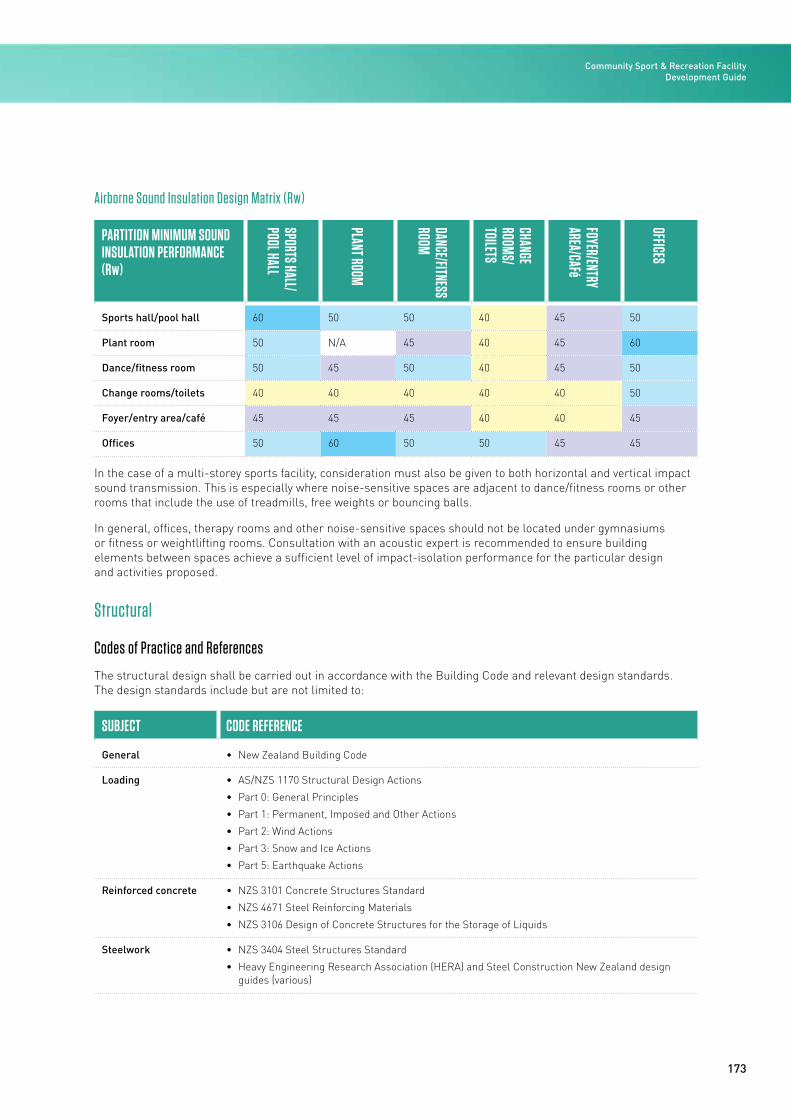
173
Airborne Sound Insulation Design Matrix (Rw)
PARTITION MINIMUM SOUND INSULATION PERFORMANCE (Rw)
SPORTS HALL/ POOL HALL
PLANT ROOM
DANCE/FITNESS ROOM
CHANGE ROOMS/TOILETS
FOYER/ENTRY AREA/CAFé
OFFICES
Sports hall/pool hall 60 50 50 40 45 50
Plant room 50 N/A 45 40 45 60
Dance/fitness room 50 45 50 40 45 50
Change rooms/toilets 40 40 40 40 40 50
Foyer/entry area/café 45 45 45 40 40 45
Offices 50 60 50 50 45 45
In the case of a multi-storey sports facility, consideration must also be given to both horizontal and vertical impact sound transmission. This is especially where noise-sensitive spaces are adjacent to dance/fitness rooms or other rooms that include the use of treadmills, free weights or bouncing balls.
In general, offices, therapy rooms and other noise-sensitive spaces should not be located under gymnasiums or fitness or weightlifting rooms. Consultation with an acoustic expert is recommended to ensure building elements between spaces achieve a sufficient level of impact-isolation performance for the particular design and activities proposed.
Structural
Codes of Practice and References
The structural design shall be carried out in accordance with the Building Code and relevant design standards. The design standards include but are not limited to:
SUBJECT CODE REFERENCE
General • New Zealand Building Code
Loading • AS/NZS 1170 Structural Design Actions
• Part 0: General Principles
• Part 1: Permanent, Imposed and Other Actions
• Part 2: Wind Actions
• Part 3: Snow and Ice Actions
• Part 5: Earthquake Actions
Reinforced concrete • NZS 3101 Concrete Structures Standard
• NZS 4671 Steel Reinforcing Materials
• NZS 3106 Design of Concrete Structures for the Storage of Liquids
Steelwork • NZS 3404 Steel Structures Standard
• Heavy Engineering Research Association (HERA) and Steel Construction New Zealand design guides (various)
Community Sport & Recreation Facility Development Guide
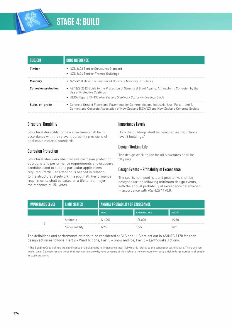
174
SUBJECT CODE REFERENCE
Timber • NZS 3603 Timber Structures Standard
• NZS 3604 Timber-Framed Buildings
Masonry • NZS 4230 Design of Reinforced Concrete Masonry Structures
Corrosion protection • AS/NZS 2312 Guide to the Protection of Structural Steel Against Atmospheric Corrosion by the Use of Protective Coatings
• HERA Report R4-133 New Zealand Steelwork Corrosion Coatings Guide
Slabs-on-grade • Concrete Ground Floors and Pavements for Commercial and Industrial Use, Parts 1 and 2, Cement and Concrete Association of New Zealand (CCANZ) and New Zealand Concrete Society
Structural Durability
Structural durability for new structures shall be in accordance with the relevant durability provisions of applicable material standards.
Corrosion Protection
Structural steelwork shall receive corrosion protection appropriate to performance requirements and exposure conditions and to suit the particular applications required. Particular attention is needed in relation to the structural steelwork in a pool hall. Performance requirements shall be based on a life to first major maintenance of 15+ years.
Importance Levels
Both the buildings shall be designed as importance level 3 buildings.*
Design Working Life
The design working life for all structures shall be 50 years.
Design Events – Probability of Exceedance
The sports hall, pool hall and pool tanks shall be designed for the following minimum design events, with the annual probability of exceedance determined in accordance with AS/NZS 1170.0.
IMPORTANCE LEVEL LIMIT STATES ANNUAL PROBABILITY OF EXCEEDANCE
WIND EARTHQUAKE SNOW
3Ultimate 1/1,000 1/1,000 1/250
Serviceability 1/25 1/25 1/25
The definitions and performance criteria to be considered at SLS and ULS are set out in AS/NZS 1170 for each design action as follows: Part 2 – Wind Actions, Part 3 – Snow and Ice, Part 5 – Earthquake Actions.
* The Building Code defines the significance of a building by its importance level (IL) which is related to the consequences of failure. There are five levels. Level 3 structures are those that may contain crowds, have contents of high value to the community or pose a risk to large numbers of people in close proximity.
STAGE 4: BUILD
175
Structural Robustness
Structures shall be tied together in both the horizontal and the vertical planes so that the structure can withstand an earthquake event without being disproportionally damaged. Section 6 of AS/NZS 1170.0 gives general guidance on provisions for structural robustness.
If poor or liquefaction-prone ground is encountered then it may be prudent to consider higher than Building Code minimum levels of design for serviceability, to limit the likelihood of time-consuming and costly repairs to the structure after a moderate earthquake event.
Low Damage Design
The adopted structural solutions shall take into consideration the principles of low damage design. In particular, for ULS events the design should limit structural member damage to localised, easily repairable elements, minimise non-structural damage, and also be durable and cost-effective.
Design Loadings
Permanent actions (dead load + superimposed dead load) and imposed actions including live load, wind, snow, earthquake, liquid pressure, ground water and earth pressure, shall all be determined in accordance with the relevant parts and sections of AS/NZS 1170.
Design loadings shall be determined for required serviceability and ULS return periods set out in Section 3 – Structural.
Seismic Actions
Seismic actions shall be determined in accordance with AS/NZS 1170.5 as noted above, with the following areas further highlighted.
General Seismic Requirements
The structures shall be configured with a clearly defined load path so that loads due to seismic actions together with gravity loads are capable of being transmitted into the ground in a predictable manner.
Where reference is made to USL earthquakes, these are defined as follows:
• Under the serviceability-level earthquake the building structure and non-structural components shall not require repair
• Under the ultimate-level earthquake the building shall be designed for life safety. The building may suffer significant damage, but the risk of collapse is appropriately low.
Site Hazard Spectra
The elastic site hazard spectra for horizontal loading, C(T), for a given return period are derived from the equation: C(T) = Ch(T) Z R N (T,D)
In the determination of C(T) using AS/NZS 1170.5 the following factors have been assumed:
• Site subsoil Class D
• Hazard factor Z = 0.3
• Return period R = 1.3 at ultimate level / = 0.25 at serviceability level
• Near fault N(T,D) = 1.0
• Building period T = to be established by calculation
Structural Irregularity
The structural form should endeavour to avoid significant irregularities. Should a chosen structure be considered irregular in accordance with AS/NZS 1170.5, the appropriate design procedures shall be followed.
Serviceability Design Criteria
Under the SLS the building structure and non-structural components shall effectively be undamaged and not require repair. To meet these criteria, special attention shall be paid to design and detailing around all support structures.
The serviceability lateral and vertical displacement limits shall be based on Table C1 of NZS 1170.0. Specific attention should be paid to the detailing and interaction of non-structural and structural elements.
The serviceability requirements, including maximum crack widths for concrete pool tanks, shall be as per NZS 3106.
Alternative types of pre-engineered pool tanks shall be designed and detailed to avoid leaks at joints, damage to waterproof membranes and pool liners such as tiling, and permanent deformation of the tank shell.
Community Sport & Recreation Facility Development Guide
176
Structural Systems
A brief description of the primary structural systems for each area of the reference facility is provided below. The structural system described is an example only for the reference facility, and other structural systems could be used, or may be considered more appropriate depending on site-specific conditions.
Sports Hall
• Superstructure
- Structural steel portal frame spanning the length of the sports hall, allowing additional portal frames to be added should future expansion be considered
- Steel cross-bracing provided at each end of the main portal frames between each of the portal columns
• Floor
- Reinforced-concrete slabs-on-grade with chosen sports flooring applied on top
• Foundations
- Shallow reinforced-concrete pad and strip footings under main structural elements
Pool Hall
• Superstructure
- Timber glulam portal frames spanning full width of pool hall
- Steel cross-bracing provided at each end of the main portal frames between each of the portal columns
• Floors
- Concrete (together with pool tank) regular joints provided within the slab with waterproofing sealants and strips applied. Concrete includes additives to reduce shrinkage and improve watertightness
• Foundations
- Shallow reinforced-concrete pad and strip footings under main structural elements
Pool Tank
• Structure
- Reinforced-concrete, cast-in-place pool walls and slab, regular joints provided within the slab with waterproofing sealants and strips applied. Concrete includes additives to reduce shrinkage and improve watertightness
Ancillary Areas
• Superstructure
- Structural steel roof rafters spanning each space from the portal frame columns
- Steel cross-bracing or masonry block walls provided to give lateral resistance and to support roof rafters
• Floor
- Reinforced-concrete slabs-on-grade with chosen sports flooring (or other typical flooring) applied on top
• Foundations
- Shallow reinforced-concrete pad and strip footings under main structural elements
STAGE 4: BUILD
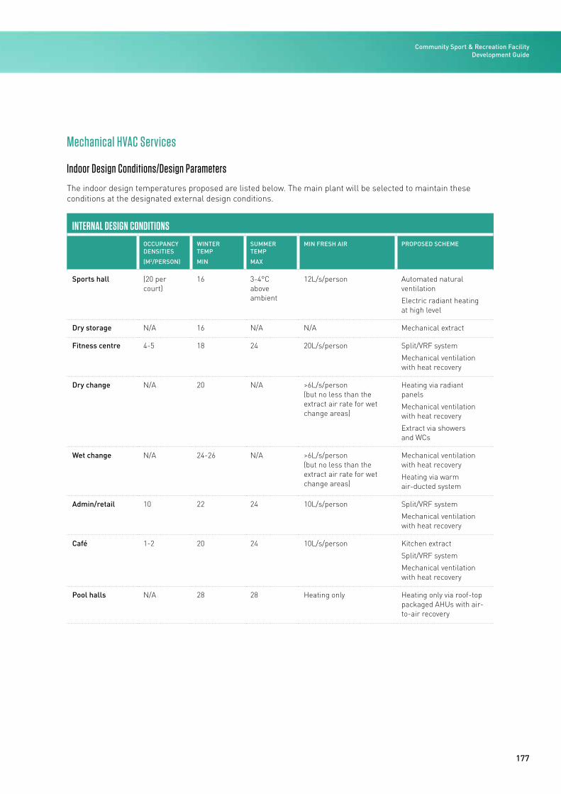
177
Mechanical HVAC Services
Indoor Design Conditions/Design Parameters
The indoor design temperatures proposed are listed below. The main plant will be selected to maintain these conditions at the designated external design conditions.
INTERNAL DESIGN CONDITIONS
OCCUPANCY DENSITIES
(M2/PERSON)
WINTER TEMP
MIN
SUMMER TEMP
MAX
MIN FRESH AIR PROPOSED SCHEME
Sports hall (20 per court)
16 3-4°C above ambient
12L/s/person Automated natural ventilation
Electric radiant heating at high level
Dry storage N/A 16 N/A N/A Mechanical extract
Fitness centre 4-5 18 24 20L/s/person Split/VRF system
Mechanical ventilation with heat recovery
Dry change N/A 20 N/A >6L/s/person (but no less than the extract air rate for wet change areas)
Heating via radiant panels
Mechanical ventilation with heat recovery
Extract via showers and WCs
Wet change N/A 24-26 N/A >6L/s/person (but no less than the extract air rate for wet change areas)
Mechanical ventilation with heat recovery
Heating via warm air-ducted system
Admin/retail 10 22 24 10L/s/person Split/VRF system
Mechanical ventilation with heat recovery
Café 1-2 20 24 10L/s/person Kitchen extract
Split/VRF system
Mechanical ventilation with heat recovery
Pool halls N/A 28 28 Heating only Heating only via roof-top packaged AHUs with air-to-air recovery
Community Sport & Recreation Facility Development Guide
178
Utilities – Natural Gas (where available)
Where gas is available, a new connection to a local utility provider will be required, complete with new pipework and a new meter station/pressure regulator in a protective cage.
Within the building such gas will need to be reticulated to serve the café kitchen, gas-fired boiler and gas-fired radiant heaters etc.
Sports Hall
Natural ventilation will be provided through perimeter inlet louvres located on two sides of the building and roof-mounted ridge vents or high-level louvres in the façade.
Louvres and vents shall be provided with actuators and a ventilation control system, providing automatic operation to maintain temperature conditions and reduce overheating.
Heating will be provided through high-level electric radiant panel heaters.
Dry Stores
Mechanical extract ventilation via a roof-mounted fan will provide sufficient air change rates, with air being drawn in from the adjacent sports hall through internal wall or door louvres.
Fitness Centre
The fitness centre consists of the main gym room and a studio. A heat recovery AHU will provide a ducted outdoor supply along with an extract system. The AHU will be served via an LTHW heating coil from the central plant to provide final tempering of the air after the heat exchange process.
Local zone heating/cooling of each space will be provided via a VRF system or split DX systems. For this application, four-way ceiling cassettes are the most cost-effective.
Dry Change
This zone essentially forms part of the fitness centre and will be served by the plant described above.
Local heating will be via radiant ceiling panels. Although these are not an efficient source of heating, the capital cost is low and the annual heating demand is envisaged to be low for this space given it is an internal zone. Adjacent WCs will be provided with an extract system to draw air from the change rooms.
Admin Offices/Staff Room/Meeting Room
Local zone heating/cooling of each space will be provided via a VRF system or split DX systems. Smaller rooms will be served by one-way cassettes or hi-wall units, whereas larger spaces will be provided with four-way ceiling cassettes.
As this zone would operate typically during normal business hours, a separate heat recovery outdoor air system will provide outdoor air to these spaces.
Entrance Lobby/Foyer/Reception/Café Seating
Heating/cooling to the reception area will be provided via a VRF system or split DX systems. Owing to intermittent occupancy, a background level of outdoor air will be provided from the AHU serving the fitness centre and this will also provide make-up air for the WCs and kitchen extract. Localised zone heating/cooling of the reception space and café seating will be provided via a VRF system or split DX systems.
Café Kitchen
The café kitchen will be provided with mechanical extract ventilation and a stainless-steel kitchen hood. A roof-mounted fan with vertical discharge will be provided.
Plant Rooms
Fixed weatherproof louvres at high and low levels in the façade will provide air movement and reduce overheating.
STAGE 4: BUILD
179
Pool Hall HVAC Systems
Pool Hall Ventilation
The reference facility is based on a typical 100 percent outside air ventilation system, pre-heated, and a typical 100 percent outside air exhaust with heat recovery.
The total supply air quantity for the pool hall would be in the order of four to six ACH. Based on six ACH, the reference facility pool hall requires approximately 18m3/s outside air.
The systems shall be designed so that the outside air intake quantity can be automatically varied, in response to pool hall relative humidity, from the minimum required to satisfy occupancy demands to 100 percent of the total air required for satisfactory ventilation of the respective pool hall.
The air-handling systems shall incorporate air-to-air heat recovery systems to transfer heat from the return air to the incoming outside air for energy use optimisation. The air-to-air heat recovery systems shall utilise plate-type heat exchangers.
Based on a location where natural gas is not available, a heat pump solution to heat the pool hall air is proposed.
An air distribution system comprising high-level ducted air supply and high-level return shall be utilised, with air throws and distribution designed to assist with the removal of DBPs from the pool hall and the minimisation of condensation on the façade, while keeping draughts to acceptable levels.
Particular care shall be taken in conjunction with the architect for the coverage of the roof structure to minimise condensation.
The preferred ductwork is lightweight textile ducts subject to the required throws being able to be achieved for effective air movement to minimise condensation and assist with the removal of DBPs.
The reference facility would require three roof-top packaged heat pump units complete with integral air-to-air heat recovery heat exchangers. The units will require specific anti-corrosion treatment to suit a pool environment. The units are required to be located outside, usually roof-mounted.
Change Room Ventilation
The change rooms require heated air for occupant comfort during changing and sufficient extract to remove odours and moisture from the change, shower and WC areas. The air would be heated from the common pool heating heat pump generating heating water.
A dedicated AHU, 1,200L/s capacity with heating only, will supply air to the change room. A dedicated exhaust fan will provide 1,200L/s exhaust air out of the room. Heat recovery could be incorporated into this system if a running cost analysis proves this worthwhile.
Pool Storage Ventilation
Ventilation to pool storage areas could be a mix of dedicated exhaust and some pool hall ventilation air from the main pool hall AHU.
Plant Room Ventilation
The pool water plant room should be ventilated via mechanical exhaust and outside air make-up. The electrical distribution board and control panels should be fitted with a proprietary pressurisation ventilation scrubber fan to protect electrical components from corrosion.
Hydraulic Services
Potable Cold Water Distribution for Domestic Purposes
The mains water should be supplied at a minimum of three to four bars at the point of supply. The water meters should be located in an underground chamber on hard surfaces at the site boundary. The incoming meter should be sized to supply potable water to the toilets and shower areas, and a separate dedicated meter and supply will be sized to serve the pool water treatment plant.
The cold water system would consist of:
• 100mm domestic cold water connections from the network utility supply system, each complete with a council water meter and RPZ (reduced pressure zone) -type backflow preventer
• 100mm fire cold water connections from the network utility supply system, each complete with a council water meter and RPZ-type backflow preventer
Community Sport & Recreation Facility Development Guide
180
• Isolating valves, complete with appropriate backflow prevention for services’ trades including mechanical, irrigation and fire hose reel system
• Pipework to supply the ablutions, header flush tanks, utility rooms, kitchen, café, plant rooms, building services, irrigation, hose taps, fire hose reel system and DHW plant
• Adequate provision around the complex of hose taps with vacuum breakers to serve grease trap areas, rubbish rooms, loading docks, plant rooms and roof wash-down
• Valved connections to each ablution (staff, public, teams, kitchens, laundry and first aid rooms).
The following water economy measures shall be incorporated into the design:
• Water-saving tapware, spring-loaded spray taps
• Reduced flow rate to the showers, push buttons with adjustable timers on all showers.
Domestic Hot Water Generation and Distribution
A DHW generation plant is to be provided to serve the shower areas and any retail or hospitality tenancies.
The hot water system would consist of:
• The DHW, pre-heated by the pool, heating the heat pump hot water to 40°C and then supplied to satellite hot water cylinders around the site. Suggest two 400L pre-heat cylinders
• An electric hot water cylinder and electric elements for the café tenancy. Suggest 180L with 6kW heating elements
• Electric hot water cylinders for local distribution to the showers, sinks, wash-hand basins and toilets in the facility.
• For the basis of this reference facility, a DHW storage volume of approximately 2,000-2,500L. Hot water would be pumped to all fixtures
• Branch pipes with flow meters, which will be provided to serve the individual tenant spaces to allow them to be metered and billed separately for DHW.
Consideration could be given to solar hot water boost heating, but this energy is weather/season dependent.
Stormwater Drainage
Surface-water drainage including rainwater outlets, hoppers, drains and gutters is to be provided to serve roof areas.
The stormwater system would consist of:
• Stormwater downpipes, outlets and overflows from main roof gutters and for canopies and decks
• Stormwater drains and heavy-duty rainwater outlets from walkway and concourse areas open to outside.
Sanitary Drainage
The internal sanitary drainage systems are to be designed to comply with local authority requirements and the local system network.
The sanitary systems are to operate by means of gravity serving all fittings from ground level. Soil/waste stacks with anti-siphon/relief vents are to collect discharges from all the fittings associated with the development. All vent pipes are to terminate through the roof and discharge to the atmosphere.
The sanitary drainage system would consist of:
• Drainage from ablutions, kitchens, tenancies, laundry, rubbish rooms, plant rooms and concessions
• Greasy waste systems to sanitary fixtures and appliances that discharge grease from areas within the complex from the kitchen (run to external below-ground grease trap located in an accessible location prior to entering the network utility system).
STAGE 4: BUILD
181
Pool Water Services
Materials and Protective Coatings
The materials and finishes shall be selected for satisfactory performance against the corrosive action of pool water and various pool chemicals, including due care for partially wet services.
Plant and Equipment
The plant and equipment shall be selected so that ongoing support for operation, maintenance and servicing can be assured and that the plant items have demonstrated performance in service in New Zealand.
Pool Water Recirculation Pumps
Recirculation pump sets shall be sized to deliver the required pool water circulation rate as well as the desired flow for effective backwash of the filtration system.
The minimum acceptable configuration for each pool shall be two identical end suction pumps complete with variable frequency drive control, with the capacity of each pump being 50 percent of the total design flow rate for the respective space, at the desired head.
Smaller water spaces such as spa and toddlers’ pools may be provided with single pump systems.
Each pump shall be provided with a hair and lint strainer.
Pump sizes are:
• Main pool – two pumps (duty/standby), 60-70L/s each at approximately 300kPa
• LTS/leisure area pool – two pumps (duty/standby), 35-40L/s each at approximately 300kPa
• Spa pool – two pumps (duty/standby), 5-6L/s each at approximately 300kPa
• Toddlers’ pool – two pumps (duty/standby), 5-6L/s each at approximately 300kPa
• Water features for LTS pool – 5L/s each at approximately 200kPa.
The water feature/play systems shall be generally water or air based or a combination and could include fountains, water spouts/jets, geysers (with air), air beds/bubblers, mini water slides etc.
These systems shall include the associated water and air reticulation, treatment, pumps, blowers, controls and feature/play equipment. These shall be flexible systems to allow adjustment for fine-tuning their performance.
Local and remote control facilities shall be incorporated to allow easy management by pool operators.
Pool Water Filtration Units
Units with benign filter media shall be chosen, utilising media with no known operator H&S risks. Where a regular addition of filter media is required, provisions shall be incorporated for the safe storage, handling, loading, introduction and disposal of the media, including necessary tank(s) with stirrer, material handling equipment, hood(s), ventilation etc.
Medium-rate, deep-bed pressure sand filters with air scour-assisted backwash are preferred for the particulate filtration of the pool water streams. The pressure sand filters shall have fibreglass shells with access manholes and inspection ports. The media bed depth shall be no less than 1,200mm with a free-board of no less than 600mm. The design and construction of the sand filters shall be so that they can be converted to multi-media types by a mere change of media. The filters shall be sized for a filtration rate of less than 25m/hr. Each filter unit shall be capable of being individually backwashed. Filters should be set up in a ‘shunt backwash’ configuration to allow the use of filtered water for backwash. Provision of equipment for automatic dosing of coagulant/flocculent shall be included, such as mixing tank(s) and dosing pumps.
Proposed filtration requirements for the facility are:
• Main pool – 6x1.4m diameter, vertical deep-bed sand filters
• LTS/leisure area pool – 4x1.4m diameter vertical, deep-bed sand filters
• Spa pool – 1x0.75m diameter, vertical, deep-bed sand filter
• Toddlers’ pool – 1x0.9m diameter, vertical deep-bed sand filter.
Community Sport & Recreation Facility Development Guide
182
Each filter shall be capable of being backwashed independently, with continued filtered and treated water supply to the respective water space, albeit at a reduced rate.
A common backwash retention system shall be provided with discharge at a controlled rate to trade waste to ensure compliance with the discharge rate limitations imposed by local authorities. The tanks shall be sized to permit backwash of at least two pool systems in a day. An alarm and pump interlock system shall be provided to prevent accidental overflow. The installation and tank discharge flow rate shall comply with the requirements of the local sewerage authority.
Disinfection and Water Chemistry Control
Fully automatic primary and supplementary water disinfection is to be provided to achieve compliant, satisfactory performance at all times. Chemical systems to enable proper chemical balance and pH will need to be selected to suit the disinfectant chosen.
Primary Disinfection
Primary disinfection shall be chlorine based.
Disinfection shall be based on the leased, on-site generation of 2.5 percent hypo complete with associated provisions for salt storage/handling, back-up hypo storage, 2.5 percent hypo storage tank, safety, ventilation etc.
Disinfectant dosing shall be controlled in response to continuous monitoring of the free available chlorine level in the water. The dosing pumps shall be of automatically adjustable capacity type and sized for peak requirement.
Necessary alarms for over-dosing or similar shall be incorporated.
Secondary Disinfection
Secondary disinfection is to be provided for the ability to reduce harmful DBPs and to kill parasites such as cryptosporidium.
A full-flow, medium-pressure, UV-based treatment for each water system is the preference. The UV units shall be modulating type with automatic control based on the combined chlorine level and shall be complete with automatic cleaning systems.
pH Control Including Water Balance
The facility for pH correction shall be designed to suit the chlorination method selected and be fully automatic in operation. For the proposed liquid-chlorine-based disinfection, the pH control is expected to be based on CO2 gas.
To assist with ensuring a satisfactory water balance, a provision to allow controlled dosing of supplementary chemicals, including associated mixing tanks, dosing pumps etc, shall be incorporated.
The make-up water for normal operation shall be introduced to the balance tanks under an automatic level control with metering. Manual quick-fill control shall also be provided.
Provision for controlled water bleed for dilution shall be incorporated.
Pool Covers
Thermal pool covers shall be incorporated for the water spaces to assist with minimising evaporation and heat loss during non-use periods, such as nights. Pool covers shall be tough, tear resistant, non-permeable, non-toxic, UV stabilised and chemically resistant to pool water and chemicals, complete with reinforced edging. The covers shall be custom designed to suit the pool shape, orientation and storage arrangement. The design shall include suitable reels and a motorised winch(es) etc to enable easy handling for spreading over the pool before night and rolling back into storage in the morning by the pool operators. Dedicated permanent storage spaces shall be designed into the facility.
Pool Hydraulics and Pipework
The pool hydraulics system shall cover:
• Filtered-water return pipework from plant room to the pools/features with inlet nozzles/diffusers
• Soiled-water supply pipework from the wet decks to the balance tanks
• Extra low-level supply pipework from the pools to the balance tanks with pipework and control valves
• Pipework for water features, including associated pumps, air blowers etc
• Pipework interconnecting the various plant items, including respective balance tanks.
STAGE 4: BUILD
183
The function of the pool hydraulic system is to transport treated and filtered water from the treatment plant to the respective water space and back, and it should be arranged so that the water is continuously replaced in all parts of the pool. The system shall enable a thorough mixing of the treated and filtered disinfecting water with the water in the pool, discharging the pollutants by displacement.
Pipework and Valves
All pipework shall be suitable for handling chlorinated pool water, and therefore robust, non-metallic pipework is desired such as ABS PN12 with compatible fittings. Pipework for the transport of chemicals shall be selected to suit the material serviced, with any flexible tubing routed in conduit or similar for mechanical protection.
Valves shall be incorporated to facilitate isolation and balancing. Valves shall be located for accessibility complete with necessary safe access provisions.
Balance Tanks
The main pool and leisure/LTS pools will each require a balance tank – two in total. The balance tank would be located between the pool tank below the concourse.
Balance tanks shall be amply sized, taking into account bather displacement, wave action and backwash requirements. The sizing shall be based on recommendations of NZS 4441 and appropriate professional experience.
Each balance tank will require typically:
• Domestic cold water make-up water float valve
• Pump suction sump with pump anti-vortex suction plate
• Equilibrium float valve
• Trafficable sealed access hatch into balance tank from concourse complete with access ladder into tank
• Soiled-water return pipework from pool
• Vent pipes and remote level indicators.
It is imagined that the toddlers’ and spa pools will be served by soiled-water return scuppers, negating the need for balance tanks.
Inlet Nozzles and Outlets
The nozzles and outlets shall be of non-metallic construction, typically plastics. The construction and installation shall ensure compliance with pool occupant safety requirements.
Location
Buried pipework (pipework not in accessible trenches or similar) shall be reinforced with the respective pool tank structure to minimise failure potential.
Ancillary Indications, Control and Monitoring
All necessary gauges, flow meters etc shall be incorporated to facilitate efficient and effective plant operation, including, but not limited to:
• Pressure gauges across all strainers, pumps and filter vessels
• Circulation flow measurement for each water space system
• Make-up water flow measurement of each water space
• Backwash discharge flow measurement for the facility.
Central control, monitoring and indication shall include touch-screen:
• Manual control of major equipment items, including water play equipment and hydroslides
• Changing of set points, start/stop programming etc
• Status indication of all major equipment, including faults, speed etc
• Flow rates for each of the circulation/make-up/discharge meters for each water space balance tank water level’s and their water quality parameters such as levels of free available chlorine, combined chlorine and pH including Hi/Lo alarms
• Water space temperatures including Hi/Lo alarms
• Status and percentage operating capacity for the UV units
• Hi/Lo content for chemicals such as hypo and CO2
• Backwash retention tank levels, including overflow alarm.
Community Sport & Recreation Facility Development Guide
184
Pool Heating
A 500-600kW air-cooled heat pump will be used to generate heating water for the pool heating system. If gas is available at the site then a gas-fired boiler would also be a suitable heat generator. The heating capacity of the heat pump is dictated by the rate of returning the pool(s) back to operation from empty, ie, heating the filling pods.
LTHW heating water will be produced at 45-50°C and pumped throughout the building. The heat pump shall be selected so that it is able to produce condenser water at 50°C to allow for flexibility in the system in the future.
The heat pump would be located outside and heating water pumped throughout the building to:
• Four-plate heat exchangers for each of the four pools
• AHU serving the change room ventilation
• Pre-heat hot water storage for DHW
• Other ventilation heating AHUs.
The pipework should be welded schedule-40 steel pipework. The pumping regime could be primary-only duty/standby pumps in constant flow configuration with three-port control valves.
Each pool heating system shall also have the capacity and capability for quick pull-up of temperature after a full refill. The heat-up rate for larger pools is suggested to be in the 0.25°-0.5°C/hr range, while that for the smaller pools shall be such to allow heat-up in as little time as practical, to minimise operational down-time after refill subject to suitability from structural aspects.
Plate heat exchanger materials shall be selected to provide adequate protection against corrosion by pool water.
Electrical Services
Electrical Substations
Electrical substations will be provided to the facility and positioned as close as physically possible to the building or preferably integrated with the building. The substations will be designed to comply with the local lines company’s design protocols. This is to ensure commonality of equipment types, rapid replacement should equipment failure occur, familiarity for local specialist high-voltage contractors, and flexibility for future change or expansion.
Each substation will consist of 11Kv ring main circuit breakers of a type commonly used by the local lines company’s network. The ring main units will be configured so that spare switches could be integrated to enable aligned complexes to be constructed adjacent to the project.
The substation will be a minimum of one 500kVA; 11,000:400V oil-cooled transformers.
The substations will be two-hour fire separation from the main facility and will be located at ground level with 24-hour/seven-day access from the adjacent streets for the local lines company. For smaller facilities with a small electrical load, these could be external pad-mounted kiosks rather than a dedicated building.
400V Distribution Philosophy
Low-voltage distribution encompasses the distribution of electricity downstream of the substations outlined above. It includes the 400V main switchboards, diesel generation, the UPS, main and sub-main cabling, switchboards, and sub-circuit cabling as well as associated systems including earthing, metering, and power control and monitoring.
Major plant and equipment will be located above ground level within designated plant areas. This will ensure that plant and equipment can be accessed for service and maintenance while the facility is operational.
Primary horizontal cable access through the building will be provided through in-ground cable ducts, via ceiling voids, at high level above fitted-out areas and within service spaces. All routes will be designed to enable access for maintenance or future change with minimal disruption to the operation of the facility.
STAGE 4: BUILD
185
Vertical risers will generally be located adjacent to structural and other vertical building elements to minimise their impact on any future re-planning. Electrical equipment located at ground level will generally consist of:
• Main switchboards
• Central supply and distribution switchboards
• Distribution cabling
• A diesel generator(s), if deemed appropriate.
Space will be made available for future plant modifications and/or additions to support future facility upgrades or changes.
Distribution boards will be located within the areas that they serve and will be positioned to minimise the cost re-planning layouts. Note that planning constraints may require some distribution boards to be located outside the areas that they serve.
400V Main Switchboards
A 400V main switchboard will be provided adjacent to (preferably within 20m) of each substation to supply the facility/site. The main switchboards will be of fully Type Tested Form 4b construction configured in sections, with Castell keyed bus couplers linking the sections, where provided. Provision will be included for the synchronous connection (via the automatic transfer switch facility) of 400V diesel-powered generation up to 1,000kVA at the main switchboard.
Each main switchboard will have separate sections for:
• Safety systems – the safety systems bus shall be able to be supplied automatically from the diesel generation, whether temporarily or permanently installed
• General light and power
• Landlord services
• Tenancy services
• Specialist essential services.
Provision will be made within the main switchboards for future expansion of the facility, including spare capacity for possible ‘moves and changes’ within the facility. A minimum of 20 percent spatial capacity will be provided.
Power factor correction will primarily be provided at source (within the particular equipment) or within the major mechanical plant motor control centres. Additional power factor correction will be provided at each of the main switchboards for any remnant requirement. The power factor will be corrected to 0.95 as a minimum.
Transient/surge-protection devices will be provided at each main switchboard as part of an overall protection system for the facility as subsequently detailed.
Diesel-Engine-Driven Electrical Generation
From an operational perspective, there is no requirement for standby generation to provide emergency supplies to these types of facility in the event of normal mains power failure.
It is, however, a very common requirement for parts of these facilities to be able to be used as a post-disaster welfare centre (civil defence centre), in particular indoor courts. Should this be the case there will be a requirement for the provision of back-up generation to those key areas.
Furthermore, should any facility be proposed to have major events, eg, competitions in the pool hall or indoor courts, such generation would be required to be connected prior to a major event to ensure continuity of service for event-critical systems. Your professional consultant team should be asked if this is a requirement.
Portable standby generation connection points should therefore be considered at the main switchboard (the size to be determined by the proposed loads to be connected) and/or at locations to suit the supply primary event areas.
Temporary generator sets would be provided complete with integrated controls, daily service tanks and sound attenuation. The sets would be located adjacent to the main switchboards or the event area that they are supporting. Dedicated areas will need to be identified during the design to accommodate these.
The main switchboard shall be configured to enable the associated generator to provide supply to basic building systems such as selected lighting, critical ventilation, communication systems and security systems, and selected general-purpose power outlets.
Community Sport & Recreation Facility Development Guide
186
To ensure that generators of the sizes required are available, strategic planning should be done to reserve them in advance and in accordance with the annual events calendar or major disaster. In some instances the operator may also choose to run generators during an event.
As an alternative to the temporary generator scenario outlined above, the option for permanently connected generator sets shall be investigated during the design stage where local lines networks operate demand-control periods. The investigation should consider the capital costs for the provision of such permanent generator sets against the electrical tariff benefits that would accrue.
This option would be based on generators permanently connected to the site main switchboard and configured to operate in both standby and synchronous modes. The option would include all aspects associated with a permanent generator installation, including the provision of sound attenuation, bulk diesel fuel storage, automatic transfer switchgear and exhaust, and resource consent considerations. In synchronous configuration the sets would start automatically in response to the line company’s control period demand signal and operate to reduce site maximum demand.
Sub-main Cabling
Sub-main cabling will be installed from the main switchboards to the respective downstream switchboards.
Cabling will, wherever practical, be routed via in-ground cable ducts to vertical risers located at key positions throughout the building to ensure maximum flexibility to the main operational levels. Outside the in-ground cable ducts, cabling will be routed via ceiling spaces, service walkways and back-of-house service areas. Vertical access through the building will be provided adjacent to structural and other vertical building elements so as to minimise the impact on any future re-planning of layouts. Where a cable tray and ladder are used, consideration shall be given to its location and material used to prevent deterioration through corrosion.
Sub-main routes will be carefully designed to avoid proximity to areas susceptible to electromagnetic interference. Particularly sensitive areas will include: central communications equipment and primary distribution copper cabling, computer-intensive areas, audio visual and sound equipment and cabling, and outside broadcast cable pathways etc. The mitigation measures for any interference will consist of:
• Segregation – adequate distance between data and power systems
• Shielding – where segregation is not possible, cables will be shielded to minimise the effects of the electric and magnetic fields generated
• Cable installation configuration – single-core cables will be installed in trefoil to reduce the electromagnetic interference generated
• Equipment specification – equipment will be specified to have minimal harmonic content and influence on the power supply network
• Earthing – adequate earthing of all equipment and systems will help sink harmonics and other transients to earth.
Fire-resistant cabling will be installed in all safety services equipment as required by the fire engineering design. This is expected to apply primarily to supplies to lifts, smoke exhaust equipment and fire sprinkler pumps/protection equipment.
Cable types will be selected taking into account a number of factors, including the particular service or system being supplied, the proposed cable route, the sub-main length, load type etc.
Cables to emergency loads will generally be of the fire-resistant type while cables to general loads will be of the XLPE (cross-linked polyethylene) and PVC types. Where specifically required by the fire engineering solution, low-smoke and -fume cabling will be provided. Other cable types will be used as required to service any particular load requirements, ie, cabling to hazardous areas could be PVC/steel wire armoured/PVC.
Cable routes and support systems will take into account space and access for future cable installation. Routes will be coordinated with the other cabling contracts to ensure maximum compatibility of route types and methodologies.
Cable support systems will be colour coded to assist with future identification, maintenance and modification, ie, the support systems for the cable ladder and tray networks will be colour coded generally in consultation with the facility operator, usually as follows:
• High-voltage Red
• 400/230V power and control Orange
• Phones/data/security (access control) Blue
• Fibre/co-axial Brown
• Public address/emergency warning Black
All cable support systems will be seismically braced to NZS 4191.
STAGE 4: BUILD
187
Distribution Boards
Distribution boards will be of the metal-clad cubicle pattern suited for both single- and triple-pole miniature circuit breakers. Separate lighting, power, controls and fuse distribution cabinets will be integrated as required with a typical distribution board.
Distribution boards will generally be located within the areas served and, specifically, in all tenancy areas. Locations will be chosen to provide flexibility for changes to area layouts and to allow ease of access for maintenance.
Fifty percent spare capacity (with reference to the number of miniature circuit breakers will be provided at distribution boards to allow for future expansion.
A series of dedicated and combined distribution boards will be provided for each operational, tenancy and plant area including:
• Leisure water area
• Multi-purpose pool area
• Fitness centre
• Support function area
• Reception
• Café
• Plant
• Storage
• Community courts
• Change facilities
• Health, fitness, and well-being areas (including studios)
• Function spaces
• Main facility street
• External areas (via external link/pillar boxes)
• Service tunnels (if provided).
Switchboards supplying the multi-purpose pool area and the indoor courts will be configured so that they can be supplied from either a temporary or a permanent diesel generation plant, to ensure that a robust back-up supply is available to these areas during important sporting and associated events.
A similar facility will be provided to the community court area so that it could be used as part of a post-disaster welfare/civil defence area if required.
Metering, Monitoring and Load Management
The metering to these types of facility is most likely to have a time-of-use and demand-based tariff structure for major consumers with local lines companies. Such tariffs are made up of various charges, a number of which are based on the kVA demand of the installation.
The incentive with such a charging system is to manage kVA demand in conjunction with the supply authority’s demand profile. The ability to monitor and control demand should therefore form a fundamental part of the building/energy management system
It is envisaged that the features incorporated within the electrical systems to enable this monitoring and control will include:
• Energy retailer tariff metering
• Building area electrical metering
• Diesel generator control systems (if permanently installed)
• Lighting control and monitoring systems
• Automatic power factor correction.
The centralised monitoring, recording and control of the building load will be interfaced with the building management and control system.
It is envisaged that electricity retailer tariff metering will occur at 400V within the main switchboard (summation metering). The particular tariff structure will be negotiated for the facility by the operator, but is likely to include both time-of-use and demand components.
Check that metering will be provided to each electrical supply to monitor usage throughout the facility and for all key operational systems, ie, mechanical services plant rooms, all separate distribution boards, and lighting and power for all major areas.
Energy tariff meters will be provided to supplies that are intended for commercial use or lease arrangements.
Metering data will be automatically collected, collated and trended via specialist metering system software, with interface to the BMS for reporting and load management.
Community Sport & Recreation Facility Development Guide
188
Uninterruptable Power Supplies
Uninterruptable power supply (UPS) units of nominally 30 minutes’ duration at full rated load will be provided to support the following critical equipment:
• Central communications/data network equipment
• All communications/data network distribution frames equipment
• Security equipment, including closed-circuit monitoring and control equipment, and cameras
• Access-control-system monitoring equipment
• Cashier’s equipment
• Critical front-of-house computers
• Building operational and maintenance system control equipment.
The access-control-system monitoring equipment will be provided with a UPS unit of eight hours’ duration at full load.
The UPS shall consist of a combination of centralised units and distributed units, determined in consultation with the client by the professional consultant team and to suit the final locations of equipment.
General-Purpose Power Outlets
General-purpose switch socket outlets will be provided throughout the development. These will generally be of the flush-mounted pattern and located within office spaces, concessionaires, circulation routes and back-of-house areas for cleaning and servicing. Outlets will be supplied from the distribution boards serving the particular areas.
Outlet flush plates will generally be white, with red for UPS-supported outlets.
In the main, outlets will be provided with RCD (residual current device) protection. In particular, this will include outlets within public and wet areas.
Industrial three-phase, 32-amp, five-pin socket outlets of the PDL 56 series pattern will also be provided throughout all plant areas and as required for plant and building maintenance.
Cabling for electric vehicle charging points will be provided to locations within the carpark. This will be separately metered so that the costs associated with vehicle charging can be separately accounted for.
Outlets will also be located throughout the general carpark to enable connection to event and kiosk-style concessions.
Lighting
Lighting will be provided throughout the facility to meet the functional requirements of each area.
The lighting solutions will take into account the following philosophies:
• Interior illuminance levels will be in accordance with the recommended guidelines in AS/NZS 1680.0 and AS/NZS 1680.1, internationally recognised best-practice, and the requirements of applicable codes
• Lamp sources will be LED throughout – except where in specialist circumstances light fittings using LED technology are not available. Fittings installed within a common area will be provided with LEDs from the same manufacturing batch to ensure commonality of colour, temperature and performance
• Light fittings will be specially designed and constructed for LED lamp sources and will not have been adapted from fittings designed for other lamp types
• Light fitting types and installation locations will take into account maintenance requirements with respect to access (eg, no fittings would be located above pools), ongoing support, availability of spares etc
• Daylight harvesting shall be employed to maximise energy use, wherever possible
• Consistent with the architectural design concepts.
Exterior lighting performance will exceed the minimum performance requirements in AS/NZS 1158.3.1 Lighting for Roads and Public Spaces, AS/NZS 1680.2.1 and AS/NZS 1680.5 to ensure a safe, uniformly illuminated solution.
All exterior lighting that is not feature lighting (eg, carparks, walkways and security lighting) will be restricted to Type 6 luminaires in accordance with Table 2.10: Classification of Luminaires and Associated Criteria for Control and Glare and Upward Waste Light (AS/NZS 1158:3.1:2005). The lighting will be designed to comply with the requirements of the local authorities infrastructure design standards.
STAGE 4: BUILD
189
CPTED principles will be used during the design to ensure a safe external area is created.
The target illumination levels and uniformity throughout all external areas will be in accordance with lighting subcategory P6 of AS/NZS 1158.3.1, and spill light levels in compliance with the local authorities city plan ‘glare’ rules.
Event and Sports Lighting
Specialised sports floodlighting will be provided in accordance with the international recommendations as determined by CIBSE Lighting Guide 4 as required for international televised competition, competition, training and maintenance and as required following consultation with sporting bodies and organisations.
Sports covered in the design will include as a minimum swimming, netball, basketball, badminton, table tennis, health and fitness (ie, gymnasium and dance studios), movement and gymnastics.
A flexible and adaptable lighting system will be provided to the indoor court areas, particularly the event court and community court spaces, to meet the requirements of a variety of sporting and entertainment events.
A selection of pre-set lighting levels will be provided to ensure that the correct illumination is achieved for the selected event. The variety of pre-set lighting scenes will increase the flexibility of the spaces. Pre-set scenes will also include appropriate lighting for the set-up of events and post-event cleaning.
The sports lighting will be controlled by lighting control units located within the specific area and from the central control location. This system will allow the switching of various pre-sets with dimming facilities for events, and will be integrated with and control the lighting to associated areas. Emergency facilities will permit an operator to override the lighting system to provide full lighting in the event of an emergency.
Emergency and Exit Lighting
The emergency lighting and illuminated exit signage will be designed to comply with sections F6 and F8 respectively of the Building Code and the requirements of the fire safety design as outlined by the project fire engineer.
Particular emphasis will be placed on the fact that many of the spaces could have a large number of people present and that adequate lighting is a primary element in the management of panic in an emergency.
This system will be centrally computer monitored for ongoing reporting as part of building warrant of fitness requirements and to simplify maintenance.
The option for a system based on central batteries or single point units will be investigated during the design stage by the professional consultant team. The investigation will review the pros and cons of each system, particularly with respect to availability for, and ease and cost of ongoing maintenance.
Where emergency lighting and illuminated exit signage are needed within tenanted areas, it will be a requirement that the fittings be part of the overall facility’s centrally controlled and monitored system to simplify building warrant of fitness costs and processes.
Lighting Control
Lighting control will be integrated with the facility’s operations using DALI (digital addressable lighting interface) technology in all light fittings.
Centralised control and programming will be possible for all light fittings.
Intelligent lighting control panels will be provided in strategic locations throughout the facility to enable local control of selected areas. These will be pre-programmed with scenes to suit the various operational modes of the areas.
Control philosophies will incorporate, where appropriate, a response to:
• The amount of available daylight – daylight harvesting
• Space occupancy – detection and control
• Facility operational status – open, closed, special event etc
• Facility emergency status
• Security level – minimal level for maintenance of building security
• Cleaning
• Special events
• Manual override.
Community Sport & Recreation Facility Development Guide
190
Auto/off/manual override would be provided at local distribution boards to enable management staff to initiate lighting manually should communications with the central control system fail.
An interface will be provided to the building management control system to enable lighting control to be integrated with the overall facility status and control.
Lighting within tenant areas would be controlled as part of the tenants’ own control systems.
Miscellaneous Electrical Systems
Earthing and Bonding
A main earth system will be provided for the electrical network. This would include the provision of earth mats, buried conductors, rods and connections to the main structural foundation reinforcing steelwork to provide for power system earthing in accordance with latest versions of the Electricity Regulations and AS/NZS 3000 Electrical Installations.
A supplementary and equipotential bonding system will be provided. All exposed and extraneous metalwork will be bonded to the earth system. Particular care will be required around the pool/wet areas.
A separate ‘silent’ earth system would be provided to all communications cabling hub panels, the main computer equipment room, specialist audio visual equipment locations, and other sensitive electronic services. This would typically consist of 25x3mm solid copper bars to provide the increased surface area required for the sinking of high-frequency transients. The power and silent earth systems would be connected by transient earth clamps at source.
All sub-mains and sub-circuits would be provided with earth continuity conductors.
Seismic Restraint
Seismic restraint of secondary systems and equipment will be particularly important throughout the facility, given its public nature and the potential number of occupants.
Electrical and ancillary systems will be seismically restrained in accordance with NZS 4219 Seismic Performance of Engineering Systems in Buildings.
Restraint systems will be coordinated between services within the building (electrical, mechanical, fire etc) to ensure commonality of support type and shared use, wherever practicable.
Particular attention will be paid to the provision of supplementary seismic support anchor points to allow for connections to specialist event equipment and systems.
Power Factor Correction
Power factor correction units will be provided at the main switchboard. The size of each unit would be determined following a power system survey upon the completion of the building. Particular features of the power factor correction equipment will include:
• Independently mounted units of robust, modular, metal-clad construction OR, if/where possible, incorporated into the main switchboard
• Provision by a specialist manufacturer
• Construction based on proven thermal performance
• Correction nominally to 0.95-0.96
• Harmonic blocking filters
• Intelligent monitoring and control utilising the communication network infrastructure
• Capacitor voltage rating suitable for modern harmonic-intensive environments
• Switching contactors designed for switching capacitor loads
• Prudent allowance for future expansion.
Lightning, Surge and Transient Protection
A lightning risk analysis, in accordance with AS/NZS 1768 Lightning Protection, will be undertaken once the final form and configuration of the facility are determined.
Irrespective of the outcome of the lightning protection risk analysis, surge protection will be provided to all main switchboards, sub-switchboards and local distribution boards based on a primary, secondary and tertiary protection strategy.
Specific sensitive or delicate electronic equipment will be provided with localised finer surge protection as part of the fit-out or FF&E.
General Noise Levels
The maximum design sound pressure levels from mechanical plant are detailed in the acoustic stage 4 (Build) page 170 of this document. Specific requirements will need to be confirmed with the various sporting bodies during the design stage.
STAGE 4: BUILD
191
Security
General
An integrated building security system is proposed. This system will incorporate security control and general surveillance of the building at strategic locations utilising a combination of access control, alarm monitoring, and closed-circuit television (CCTV) systems.
A central security room will be located in the building, preferably adjacent to the administration/back-of-house areas. The central security room will house the main security operations workstations and CCTV monitors, and will be combined with other monitoring facilities such as the fire control equipment and BMS.
A UPS unit will provide emergency power for no less than eight hours’ duration at full load for all of the security systems.
Closed-Circuit Television
A CCTV system will be provided for general surveillance, through a combination of fixed and pan/tilt/zoom cameras, of the following areas:
• External site perimeter
• Carparking areas
• Building perimeter, including all entrances and exits
• Main lobby and internal street spaces
• Loading dock and service yard
• Reception/retail (cash sales) areas
• Entry/exit barrier systems
• Main public spaces.
All CCTV images will be archived onto a network video recording system. Storage capacity will be sized to enable the online retrieval of CCTV images for up to 31 days (based on recording all cameras at a minimum of 6fps). The system will be remotely accessible so that approved staff/personnel may access the network, eg, the Police to have access to external fixed cameras.
Image recording will be motion sensitive and incorporate vehicle- and face-recognition technology.
Access Control
An access control system will be provided to control movement into and within the facility. The control system will be configured to match the functional areas within the building and the various operational modes of the facility.
All perimeter entry and exit locations will be provided with access control in the form of proximity/pin-pad control. Cabling infrastructure will be provided to enable the retrofit of biometric control devices in the future.
Door contacts with alarms will be provided to monitor the status of all external doors, including emergency exits.
Motion detectors will be installed in places where it is necessary to monitor any movement after hours.
If vehicle barriers are provided to the carpark, these would be interfaced with the security control system.
Communications
Building Communications Cabling Network
The facility will be provided with a back-boned cabled communications infrastructure. A central communications network equipment room will be provided for the facility, which will function as the core for all communication systems. This will have the capability to be linked to other facilities operated by the same organisation via an external fibre network.
In addition to the main equipment room, the system will consist of communications frames located throughout the facility so that all areas of the building can be reached by a data cable no longer than 90m. In practice this will require a communications frame to serve zones of the facility no further than 60m away horizontally.
Each communications frame will be located within a room specifically designed for this purpose. All rooms shall provisionally be 5x4m, with the exception of the main communications network equipment room, which shall be 10x6m. The exact sizes of these rooms will be confirmed by the professional consultant team during the design stage.
In addition to the communications frames located within the building, external frames will be provided to ensure ‘compliant’ data is provided to services and equipment located within the carpark areas. The external frames shall be housed within weatherproof cabinets (nominally 1.2mWx0.8mDx1.2mH) located in the areas they serve.
Community Sport & Recreation Facility Development Guide
192
A back-bone fibre-optic cable system will link the various distribution frames to the central communications equipment. The cabling will be configured so that there are a minimum of two physically diverse pathways to each distribution frame. A minimum of 12 core multi-mode fibres shall be provided to each frame.
Distribution cabling to outlets in the field will be configured using a home-run format and an unshielded twisted-pair (UTP) configuration of the latest approved category at the time of installation (presently Category 6A). Cable management within the distribution frames will be of VisiPatch configuration.
Consolidation points will be installed throughout the facility in access locations to provide flexibility for future change.
Wherever practicable, systems within the facility will use the communications cabling infrastructure to communicate and connect to end-of-line devices, rather than specialist, dedicated cabling.
Wireless provision shall also be provided, allowing for both public and private use.
Master Aerial TelevisionA master aerial television (MATV) system will be provided to enable TV signals to be received. The system will be provided with access to a minimum of two satellite providers (including SKY) as well as normal TV channels. The system will distribute multiple high-definition channels throughout the facility via the communications network fibre back-bone (dedicated fibre) to each of the communications frames. Distribution to final outlet locations will use UTP cabling. A facility for the future provision of fibre-optic cabling to outlet locations will also be made (conduit or blow-tube).
TV jack points will be provided in selected areas of the facility by the professional consultant team during the design stage.
Free-to-Air Channels
• The MATV system will allow for the distribution of all locally available free-to-air channels plus encrypted SKY analogue and digital signals.
In-house Channels
• In-house channels will be modulated and distributed to public areas through the MATV system to the following areas, allowing for sales and advertising broadcasts:
- Reception/entrance lobby
- Café area.
Public Address and Background Music System
General Operational Criteria
A public address and background music system will be provided for the facility to enable communication with users of the building and provide background music to selected locations. The system will incorporate a combination of central and distributed amplifiers with digital audio processing for all inputs and outputs.
The system will be zoned to suit the operational and functional spaces within the building, so that separate sound and voice announcements will be able to be distributed to each area. Specific zones will include:
• Leisure water pool
• Multi-purpose pool
• LTS pool
• Movement centre
• Central support area
• Reception
• Café (potentially integrated with a stand-alone system provided by the café)
• Indoor courts
• Health, fitness and wellness (one zone for each gym/studio
• Function spaces.
STAGE 4: BUILD
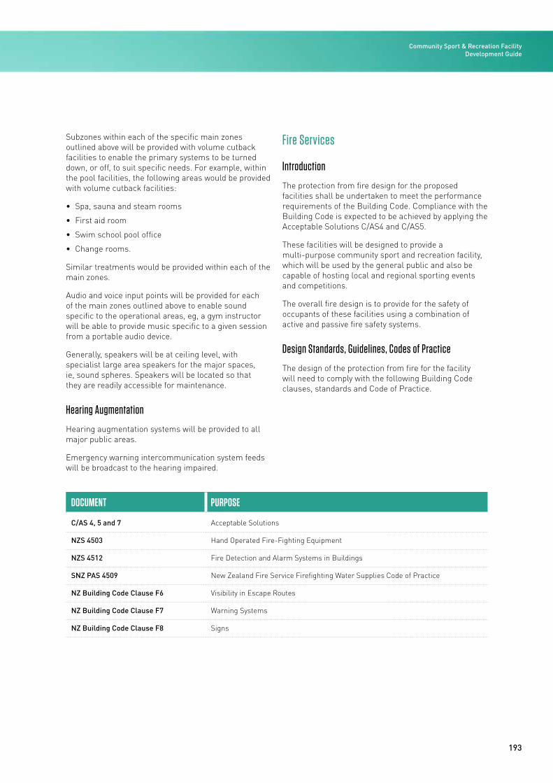
193
Subzones within each of the specific main zones outlined above will be provided with volume cutback facilities to enable the primary systems to be turned down, or off, to suit specific needs. For example, within the pool facilities, the following areas would be provided with volume cutback facilities:
• Spa, sauna and steam rooms
• First aid room
• Swim school pool office
• Change rooms.
Similar treatments would be provided within each of the main zones.
Audio and voice input points will be provided for each of the main zones outlined above to enable sound specific to the operational areas, eg, a gym instructor will be able to provide music specific to a given session from a portable audio device.
Generally, speakers will be at ceiling level, with specialist large area speakers for the major spaces, ie, sound spheres. Speakers will be located so that they are readily accessible for maintenance.
Hearing Augmentation
Hearing augmentation systems will be provided to all major public areas.
Emergency warning intercommunication system feeds will be broadcast to the hearing impaired.
Fire Services
Introduction
The protection from fire design for the proposed facilities shall be undertaken to meet the performance requirements of the Building Code. Compliance with the Building Code is expected to be achieved by applying the Acceptable Solutions C/AS4 and C/AS5.
These facilities will be designed to provide a multi-purpose community sport and recreation facility, which will be used by the general public and also be capable of hosting local and regional sporting events and competitions.
The overall fire design is to provide for the safety of occupants of these facilities using a combination of active and passive fire safety systems.
Design Standards, Guidelines, Codes of Practice
The design of the protection from fire for the facility will need to comply with the following Building Code clauses, standards and Code of Practice.
DOCUMENT PURPOSE
C/AS 4, 5 and 7 Acceptable Solutions
NZS 4503 Hand Operated Fire-Fighting Equipment
NZS 4512 Fire Detection and Alarm Systems in Buildings
SNZ PAS 4509 New Zealand Fire Service Firefighting Water Supplies Code of Practice
NZ Building Code Clause F6 Visibility in Escape Routes
NZ Building Code Clause F7 Warning Systems
NZ Building Code Clause F8 Signs
Community Sport & Recreation Facility Development Guide
194
The following fire safety systems are anticipated within the proposed facility.
Fire Detection and Alarm Systems
These facilities will require smoke-detection and associated warning systems throughout all covered areas. Thermal detection may be used in areas where smoke detection is susceptible to nuisance alarms. Fire-detection and alarm systems will comply with NZS 4512 and Clause F7 of the Building Code.
Exit Signage and Emergency Lighting System
These facilities will require emergency lighting to facilitate visibility in escape routes, and also escape route signage for wayfinding through all areas. Emergency lighting systems and exit signage will comply with Building Code Clauses F6 and F8, respectively.
Hand-Operated Firefighting Equipment
Hand-operated firefighting equipment in the form of portable extinguishers and fire blankets shall be provided in areas of specific risk, as appropriate, to comply with NZS 4503.
Water Supplies and Sprinkler Protection
The New Zealand Fire Service Firefighting Water Supplies Code of Practice (SNZ PAS 4509) shall be used to calculate the required firefighting water supply.
Sustainable Design
Introduction
The energy and sustainability strategy for the design, construction and operation of affordable sports facilities must be considered from the project outset.
It is important that the business case promotes sustainable design and includes both the tangible measurable benefits and the soft benefits to ensure that both capital costs and operating impacts are appropriately accounted for. All facilities have finite budgets and need to focus on dollar spend for best overall outcome. Pool facilities have significant energy use and operational costs, and environmental impacts – whole-of-life costing rather than capital costs should be the basis for deciding the most appropriate strategy, to focus on long-term overall value.
Sports centres with pools have a number of significant environmental impacts and are inherently high users of energy and water resources, with associated high operating costs. There is therefore scope to seek significant benefits from targeted energy-efficiency and sustainability measures.
Design Hierarchy
The design approach for swimming pools should be focused on achieving sustainable outcomes and energy savings in the most cost-effective and efficient manner. To achieve this, an integrated design approach using ‘passive’ measures to optimise the building and building envelope performance (such as optimising the building orientation and improvements to the form and fabric) should be applied before considering ‘active’ methods.
Fabric Performance
Thermal Transmittance
Part H1 of the Building Code provides the thermal transmittance (U value) criteria for building elements.
In the New Zealand climate, the indoor temperature of a sports centre is generally higher than the temperature outdoors. A large proportion of energy consumption in swimming pool buildings relates to heating the water in the pool tanks and the air in the pool hall. Therefore, to an even greater extent than in other building types, an optimised building fabric performance should be the first consideration with respect to reducing energy requirements and carbon emissions.
Design teams need to carry out their own calculations based on the specific form, fabric and systems used for each project. Computer simulations should be carried out to inform the comparison of options, and be the basis for decision-making.
Airtightness
Careful detailing to achieve a high level of airtightness is crucial, both for the external building envelope and between internal spaces with different design criteria.
In addition to this, and as part of the contractor’s responsibilities, internal partitions between the pool hall and adjacent spaces should be specified under the same criteria, due to the energy consumption associated with air leakage. Also, the carry-over of air from the pool hall to adjacent spaces can cause issues with corrosion.
STAGE 4: BUILD
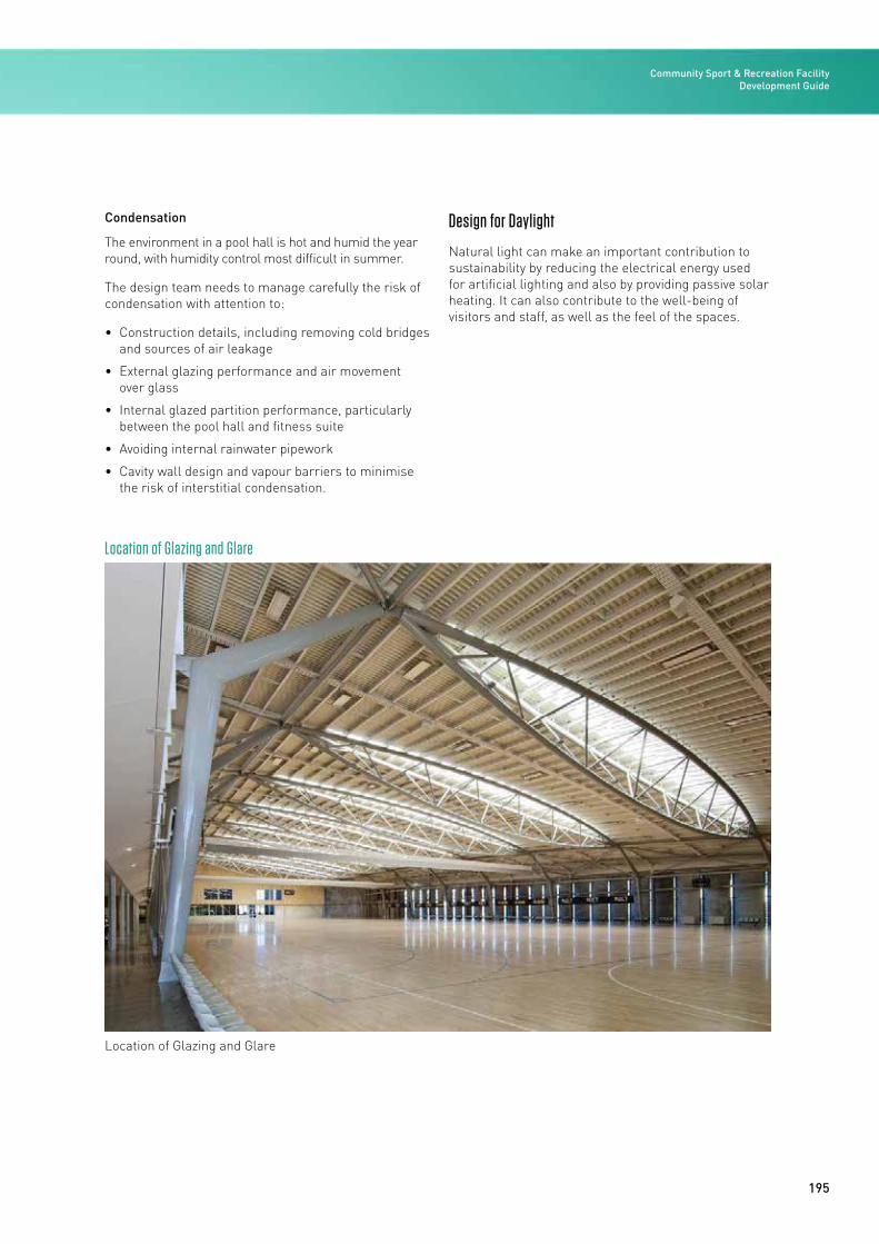
195
Condensation
The environment in a pool hall is hot and humid the year round, with humidity control most difficult in summer.
The design team needs to manage carefully the risk of condensation with attention to:
• Construction details, including removing cold bridges and sources of air leakage
• External glazing performance and air movement over glass
• Internal glazed partition performance, particularly between the pool hall and fitness suite
• Avoiding internal rainwater pipework
• Cavity wall design and vapour barriers to minimise the risk of interstitial condensation.
Design for Daylight
Natural light can make an important contribution to sustainability by reducing the electrical energy used for artificial lighting and also by providing passive solar heating. It can also contribute to the well-being of visitors and staff, as well as the feel of the spaces.
Location of Glazing and Glare
Location of Glazing and Glare
Community Sport & Recreation Facility Development Guide
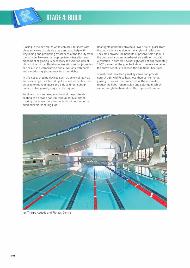
196
Glazing in the perimeter walls can provide users with pleasant views of outside areas and also help with wayfinding and promoting awareness of the facility from the outside. However, an appropriate orientation and placement of glazing is necessary to avoid the risk of glare to lifeguards. Building orientation and adjacencies can result in a compromise and elevations with north-and west-facing glazing may be unavoidable.
In this case, shading devices such as external louvres and overhangs, or internal light shelves or baffles, can be used to manage glare and diffuse direct sunlight. Solar-control glazing may also be required.
Windows that can be opened behind the pool-side seating can provide natural ventilation in summer, making the space more comfortable without requiring additional air-handling plant.
Roof lights generally provide a lower risk of glare from the pool-side areas due to the angles of reflection. They also provide the benefits of passive solar gain to the pool and a potential exhaust air path for natural ventilation in summer. A roof light area of approximately 15-20 percent of the pool hall should generally enable the above benefits to exceed the additional heat loss.
Translucent insulated panel systems can provide natural light with less heat loss than conventional glazing. However, the properties of these panels reduce the light transmission and solar gain, which can outweigh the benefits of the improved U value.
Ian Thorpe Aquatic and Fitness Centre
STAGE 4: BUILD
197
Minimising Energy Consumption
Larger Pools and Energy Consumption
A 50m pool will have a larger water volume, larger pool hall and therefore inherently higher energy consumption than smaller pools. Owing to the efficiency of support spaces and pool hall volumes, a 50m pool could achieve lower kWh/m2 than two separate 25m facilities. However, energy consumption is strongly dictated by use and a 50m pool (equipped with booms and movable floors) will aim for intensive use and occupancy, with the following implications:
• The turnover rate, dilution water volume and associated energy consumption could be proportionally higher. Note: this would enhance viability for heat recovery
• The pool hall air change rate and associated energy consumption could be higher due to higher evaporation rates. Note: this would enhance the viability of incorporating options for natural ventilation in summer.
Essential Energy-saving Techniques
A range of essential energy-saving techniques for the indicative affordable pool designs have been allowed for within the cost plan. They are included for compliance with Part L of the Building Regulations and current construction and operating practice.
These measures include:
• AHUs with heat recovery
• Modulation of fresh air provided by the ventilation system
• Variable-speed drives on all pumps, for heating, domestic services and water treatment
• LED light fittings
• Sizing of ductwork for low specific fan power
• Daylight-linked dimming on lighting in well day-lit spaces.
Metering Strategy
By providing meters and sub-meters for energy-consuming plant and areas, the building operators are provided with information to enable them to manage the use of the spaces and minimise energy consumption.
Meters should be provided to align with NABERSNZ guidelines to measure:
• >95 percent of the annual energy consumption by use
• Output from any renewable energy generation
• Energy meters on the heating branch serving pool water heating.
The following sub-meters can also be considered for inclusion:
• Energy meter on the branch serving the coil(s) in the main AHU(s) serving the pool hall
• Electricity meter on the power supply to the water treatment plant
• Electricity meter on the power supply to the cooling plant
• Water meter on the power supply for the pool top-up.
Metering data should be logged automatically, incorporating a simple user interface to allow the building manager to view and export the data.
Water Conservation
The water consumption within aquatic facilities is significant and is required for showers, WCs, catering and the make-up of the swimming pool water.
The utility costs associated with the water supply are generally more modest than those for gas or electricity, leading to longer pay-back periods for water-saving technologies. However, many energy- and water-saving measures are interdependent and all benefits must be considered when looking at pay-backs.
Community Sport & Recreation Facility Development Guide
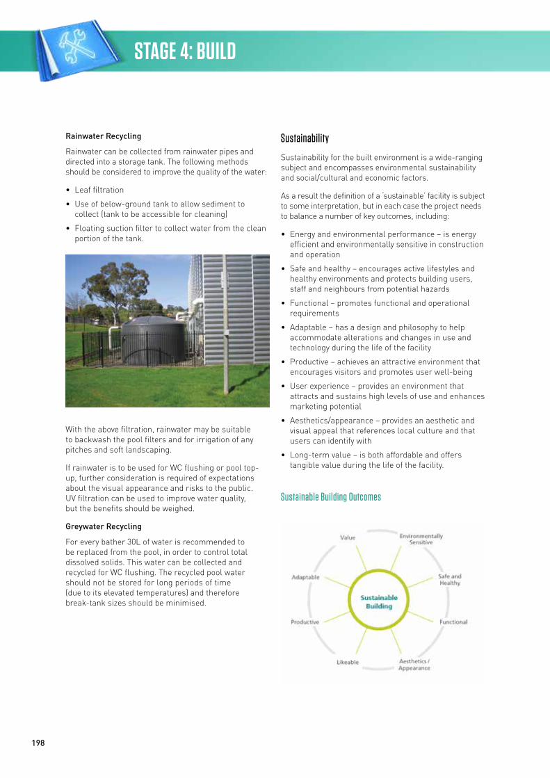
198
Rainwater Recycling
Rainwater can be collected from rainwater pipes and directed into a storage tank. The following methods should be considered to improve the quality of the water:
• Leaf filtration
• Use of below-ground tank to allow sediment to collect (tank to be accessible for cleaning)
• Floating suction filter to collect water from the clean portion of the tank.
With the above filtration, rainwater may be suitable to backwash the pool filters and for irrigation of any pitches and soft landscaping.
If rainwater is to be used for WC flushing or pool top-up, further consideration is required of expectations about the visual appearance and risks to the public. UV filtration can be used to improve water quality, but the benefits should be weighed.
Greywater Recycling
For every bather 30L of water is recommended to be replaced from the pool, in order to control total dissolved solids. This water can be collected and recycled for WC flushing. The recycled pool water should not be stored for long periods of time (due to its elevated temperatures) and therefore break-tank sizes should be minimised.
Sustainability
Sustainability for the built environment is a wide-ranging subject and encompasses environmental sustainability and social/cultural and economic factors.
As a result the definition of a ‘sustainable’ facility is subject to some interpretation, but in each case the project needs to balance a number of key outcomes, including:
• Energy and environmental performance – is energy efficient and environmentally sensitive in construction and operation
• Safe and healthy – encourages active lifestyles and healthy environments and protects building users, staff and neighbours from potential hazards
• Functional – promotes functional and operational requirements
• Adaptable – has a design and philosophy to help accommodate alterations and changes in use and technology during the life of the facility
• Productive – achieves an attractive environment that encourages visitors and promotes user well-being
• User experience – provides an environment that attracts and sustains high levels of use and enhances marketing potential
• Aesthetics/appearance – provides an aesthetic and visual appeal that references local culture and that users can identify with
• Long-term value – is both affordable and offers tangible value during the life of the facility.
Sustainable Building Outcomes
STAGE 4: BUILD
199
Environmental Strategy
The overarching environmental strategy for the project should apply a reduce-reuse-recycle approach, which seeks to minimise resource inputs before overlaying and applying effective and efficient system selections. A typical strategy for a sports facility is outlined below:
Indoor Environment
• Promote a safe and healthy indoor and outdoor environment that attracts and sustains high levels of use
Energy
• Design to take optimum advantage of daylight, passive solar heating and passive ventilation while mitigating glare and unwanted solar gains in warm weather (heat pump performance will be enhanced with constant condensing temperature)
• Recover and reuse energy
• Optimise efficiency of heating energy sources and systems
• Plan for future renewables to be incorporated
• Metering strategy for monitoring and targeting
Lighting
• Natural light provides all necessary illumination to spaces during daylight hours
• Daylight control systems and low-energy lighting systems to optimise energy savings
• Long-life lamps and easy access for replacement
• External lighting is limited to that necessary for orientation, security and safety
Water
• Water consumption is minimised for pool and ancillary uses
• Design pool water treatment plant to allow for future installation of water recycling systems
• Monitor consumption and target improvements
Emissions
• Minimise water, waste, chemical odours, noise and light pollution from the site
Materials
• Select appropriate, environmentally preferable materials for long-term value
Transport
• Promote public transport and sustainable transport options.
EECA Assistance
EECA (the Energy Efficiency and Conservation Authority) provides financial assistance for energy efficiency in projects through its Crown energy efficiency loan scheme and also through its commercial building design advice programme. Project teams should review assistance available from EECA when carrying out an options appraisal.
Soft Landings
Soft Landings is a collaborative approach to delivering buildings that meet occupants’ needs and allows the performance of the building to be optimised.
Commissioning bodies and design teams should collectively review the opportunities for a Soft Landings approach, in order to aim for a smooth handover and to get a building that operates as designed.
To aid the Soft Landings approach, in addition to the metering discussed above the BMS should enable the monitoring and logging of:
• Temperature and relative humidity in the pool hall at pool level and in spectator seating
• Visitor numbers.
For more information refer to The Soft Landings Framework – Australia & New Zealand document, which outlines how to implement Soft Landings in your scheme.
www.cibse.org/networks/regions/australia-new-zealand/the-soft-landings-framework-australia-new-zealand
Community Sport & Recreation Facility Development Guide
200
Options Roadmap for Consideration and Inclusion
The following options are provided for consideration and potential inclusion. Many of these items are considered good or best-practice for energy-efficient and environmentally responsible design outcomes. Each project and each climate zone will have differing drivers and influences. The intention is that the options below are used as part of the project decision-making process to establish the most appropriate energy and environmental inclusions for each project.
Building Form and Planning
• Site and orientate the building for passive solar design and minimum energy use
• Provide effective wind lobbies or revolving doors to minimise heat gains and losses due to open doors
• Locate energy sources to reduce losses and plant rooms near loads
• Provide sufficient space for services to allow energy-efficient design and specification
• Size plant rooms for ease of maintenance and future replacement
Building Fabric
• Utilise 3D computer simulations to inform final specifications
• Consider minimum enhanced thermal insulation to external walls
• Consider minimum enhanced thermal insulation to external roof areas
• Consider minimum enhanced thermal insulation to exposed floor areas
• Consider thermal insulation to swimming pool walls and floor
• Specification to avoid thermal bridges and weak points
• Specification to minimise air leakage through the external envelope
• Finishes to roofs and façades to align with environmental strategy
Windows and Glazing
• Size and specify to provide economical balance of thermal, visual and view requirements – use computer simulations to inform final glazing specifications
• Consider roof lights for daylight
• Provide appropriate architectural solar shading to large glazed areas to limit glare and overheating
• Specify high-performance double glazing with thermally broken frames
Heating
• Consider geothermal heating
• Adjust seasonal set points to align with ambient conditions and use
• Provide heat recovery to pool hall exhaust and all large spaces
• Variable speed pumps match flow to suit the demand
• Insulate all pipework, valves and fittings to AS 4508 as a minimum
• Consider solar thermal contribution
Cooling
• Consider heat exchanger recovers energy (sensible + latent) from exhaust air, offering ‘free’ cooling to ventilation air or via heat pump to pool
• Insulate all pipework, valves and fittings to AS 4508 as a minimum
• Use 100 percent outside air whenever ambient conditions suit
Ventilation
• Control to minimum ventilation rates
• Provide increased ventilation rates to pool areas only
• Adjust ventilation rates based on indoor air quality
• Design fan/duct systems for low pressure loss
• Variable speed fans modulate airflow rate to suit demand
STAGE 4: BUILD
201
Lighting
• Select appropriate design levels for visual comfort and energy efficiency (AS 1680)
• Specify light-coloured interior finishes
• Provide roof lights and clerestory lights for day-lit interior spaces
• Maximise the use of low-energy LED technology
• Provide daylight compensation control
• Provide occupancy control
• Label switches clearly
• Select appropriate zone sizes to balance efficiency and flexibility
• Make it easy for users to understand the lighting design and operation
Domestic Hot Water Heating
• Consider heat pump water heating
• Insulate all hot water pipework to better minimum requirements
Pool Water Services
• Undertake backwashes based on pressure drop and programme them in a sequence
• Provide automated pool covers for use during after-hours periods
• Provide variable speed drives for pool water circulation pumps to ensure correct pump speed
• Provide appropriate pool water filtration
• Provide appropriate pool water disinfection
• Design for appropriate pool water flows and turnover rates, all in accordance with NZS 4441 as a minimum
• Select appropriate water temperatures for pool bodies
• Select appropriate air temperature and relative humidity targets for pool halls
• Provide automatic control for pool water heating, pool hall HVAC, pool water disinfection and pumping
• Include prompts for manual functions such as backwash and bleed
Water Efficiency
• Install low-flow adjustable taps in kitchens and bathrooms
• Install low-flow WCs with dual flush
• Install low-flow adjustable showerheads
• Install low-flow urinals
• Consider benefits of rainwater recycling and recovery
• Install water-efficient appliances as part of the building contract
• Install water meters to monitor water consumption for all major water uses in the project
• Provide water meters to monitor water consumption and any water leakage automatically
• Provide low-water-use irrigation systems and/or provide native planting
• Treat stormwater run-off to minimise watercourse pollution
Appliances
• Install energy-efficient sports/exercise equipment
• Install energy-efficient appliances as part of the fit-out
Controls
• Widen temperature control bands for savings
• Provide central BMS for control and monitoring
• Provide BMS time scheduling with user-friendly means of grouping and adjusting zones
• Provide economiser controls to use outside air for cooling when temperatures suit
• Provide zone air quality sensors to adjust ventilation rate to achieve air quality criteria
• Provide variable-speed pumps to match flow to suit the demand
Community Sport & Recreation Facility Development Guide
202
Energy and Water Use Monitoring
• Provide metering to align with NABERSNZ recommendations
• Provide energy meter on pool water heating and coils serving pool hall ventilation
• Consider connecting sub-meters to electronic monitoring and reporting system
• Provide water metering and automatic leak detection
• Meter power supply to water treatment plant and cooling plant and include meter on pool water top-up
• Consider providing visual displays showing the energy/water use of the building
Energy Generation
• Future-proof electrical boards so that a photovoltaic (PV) cell installation for electricity generation may be integrated easily in the future
• Consider PVs
Waste
• Specify a comprehensive construction waste management plan and include a contract target for construction waste to be recycled
• Establish a comprehensive waste management plan for the operational phase of the facility
• Layouts to include recycling areas to align with best-practice guidelines
Transport
• Promote the use of public transport and more sustainable transport
• Provide priority parks for fuel-efficient vehicles
• Provide cycle storage and change facilities
• Consider charging points for electric cars
• Design cycleways and walkways as part of the site plan and landscaping
• Implement a green travel plan for the site
• Consider real-time displays in public areas to relay public transport information
• Provide sheltered, good-quality connections and waiting areas for public transport and sustainable transport connections
Materials
• Specify appropriate low-maintenance, durable materials for long-term operational value
• Specify environmentally preferable insulation, where possible
• Consider appropriate low-emission paint, where appropriate
• Consider appropriate low-emission carpets/flooring, where appropriate
• Consider appropriate emission materials, where appropriate
• Consider appropriate emission adhesives and sealants, where appropriate
• Consider appropriate formaldehyde composite wood products
• Consider appropriate zero ozone-depletion-potential (ODP) refrigerants
• Consider appropriate zero ODP thermal insulation materials
• Consider appropriate Environmental Choice certified products, where appropriate
Management and Operations
• Appoint an energy/sustainability champion to focus on improved energy efficiency and ESD outcomes
• Contractor to implement a comprehensive EMP (environmental management plan)
• Implement comprehensive IAQ (indoor air quality) plan during construction to reduce air quality problems
• Facility management team review of design proposals for ease of maintenance
• Agree list of equipment for ease of long-term management and maintenance
• Include in building services contract the requirement for full commissioning of building services to CIBSE/ASHRAE recommendations
• Include in building services contract the requirement for continual commissioning and tuning of building services for a minimum 12-month period
• Provide building users with guidance on how to operate the HVAC and lighting systems to align with the design intent
• Provide a guide outlining the design approach and technical features of the design
STAGE 4: BUILD
203
• Consider an independent commissioning agent to monitor and report on the commissioning of building services directly to the client
• Provide training for staff to understand the design intention and how best to operate the building and systems for the best outcome
• The BSRIA (Building Services Research and Information Association) Soft Landings Framework means designers and contractors stay involved with buildings beyond practical completion to assist building owners during the first months of operation (and beyond) to help fine-tune and de-bug systems, and ensure users understand the design philosophy and how to control and best use the building (preferred inclusion but depends on procurement option)
• Minimise building effluent and environmental, safety and health impacts on site and neighbours
• Reduce potential harm to the environment and people through improved management of chemicals
Benchmarking
• Benchmark the design inclusions using Green Star custom or agreed benchmarking option (note this is intended to benchmark the design only – not suggesting certification is pursued)
Capital CostsThe Rough Order of Costs included in this section are calculated using costing data derived from a number of projects completed within the last ten years. Escalation costs have been added to the analysed project costs so the listed rates are current as of the last quarter of 2017.
The rates provided are average rates for generic buildings within the city areas and should only be used for initial feasibility studies.
The costs given are based on the total floor area measured between the outer faces of external walls.
Whilst every effort has been made to ensure the accuracy of the information given herein, we do not, in any way, accept liability for loss of any kind resulting from the use by any person of such information.
Pricing Assumptions
The pricing included assumes the design and construction is at the affordable level of the design spectrum, allows for competitive market rates, good ground conditions and access.
As the figures given are for a typical building on a flat site, adjustment must be made for such factors as sloping sites, ground conditions, unusual shape and other design considerations. It should be stressed that attention must be given to particular circumstances and conditions of the project being reviewed, when using data contained herein.
No allowance has been included for locations remote from a city or town with the usual supply of materials, labour and construction skills required for the building of this type of facility. Additional allowances are needed to cover remote or rural locations.
Inclusions
The rates used include for the following:
• Construction Costs
• Fixtures, fittings and equipment
• Design fees
• Local Authority consent charges
• Siteworks, landscaping, carparking
Community Sport & Recreation Facility Development Guide
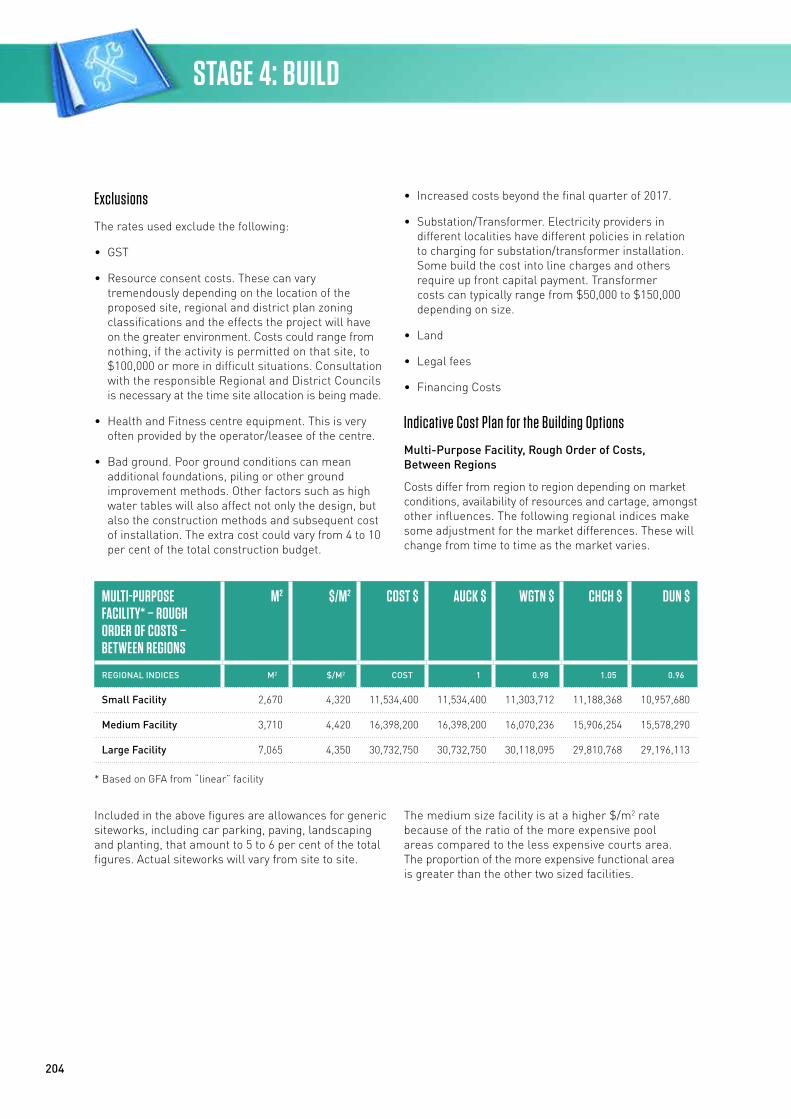
204
Exclusions
The rates used exclude the following:
• GST
• Resource consent costs. These can vary tremendously depending on the location of the proposed site, regional and district plan zoning classifications and the effects the project will have on the greater environment. Costs could range from nothing, if the activity is permitted on that site, to $100,000 or more in difficult situations. Consultation with the responsible Regional and District Councils is necessary at the time site allocation is being made.
• Health and Fitness centre equipment. This is very often provided by the operator/leasee of the centre.
• Bad ground. Poor ground conditions can mean additional foundations, piling or other ground improvement methods. Other factors such as high water tables will also affect not only the design, but also the construction methods and subsequent cost of installation. The extra cost could vary from 4 to 10 per cent of the total construction budget.
• Increased costs beyond the final quarter of 2017.
• Substation/Transformer. Electricity providers in different localities have different policies in relation to charging for substation/transformer installation. Some build the cost into line charges and others require up front capital payment. Transformer costs can typically range from $50,000 to $150,000 depending on size.
• Land
• Legal fees
• Financing Costs
Indicative Cost Plan for the Building Options
Multi-Purpose Facility, Rough Order of Costs, Between Regions
Costs differ from region to region depending on market conditions, availability of resources and cartage, amongst other influences. The following regional indices make some adjustment for the market differences. These will change from time to time as the market varies.
MULTI-PURPOSE FACILITY* – ROUGH ORDER OF COSTS – BETWEEN REGIONS
M2 $/M2 COST $ AUCK $ WGTN $ CHCH $ DUN $
REGIONAL INDICES M2 $/M2 COST 1 0.98 1.05 0.96
Small Facility 2,670 4,320 11,534,400 11,534,400 11,303,712 11,188,368 10,957,680
Medium Facility 3,710 4,420 16,398,200 16,398,200 16,070,236 15,906,254 15,578,290
Large Facility 7,065 4,350 30,732,750 30,732,750 30,118,095 29,810,768 29,196,113
* Based on GFA from “linear” facility
Included in the above figures are allowances for generic siteworks, including car parking, paving, landscaping and planting, that amount to 5 to 6 per cent of the total figures. Actual siteworks will vary from site to site.
The medium size facility is at a higher $/m2 rate because of the ratio of the more expensive pool areas compared to the less expensive courts area. The proportion of the more expensive functional area is greater than the other two sized facilities.
STAGE 4: BUILD
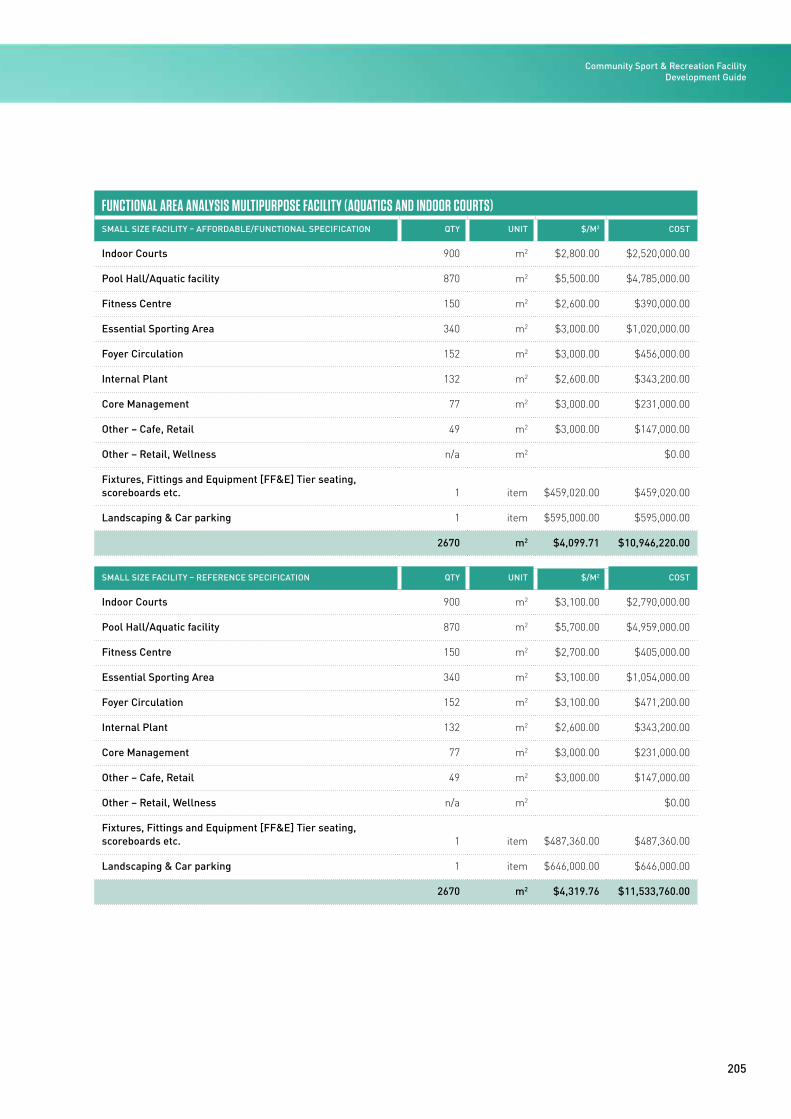
205
FUNCTIONAL AREA ANALYSIS MULTIPURPOSE FACILITY (AQUATICS AND INDOOR COURTS)SMALL SIZE FACILITY – AFFORDABLE/FUNCTIONAL SPECIFICATION QTY UNIT $/M2 COST
Indoor Courts 900 m2 $2,800.00 $2,520,000.00
Pool Hall/Aquatic facility 870 m2 $5,500.00 $4,785,000.00
Fitness Centre 150 m2 $2,600.00 $390,000.00
Essential Sporting Area 340 m2 $3,000.00 $1,020,000.00
Foyer Circulation 152 m2 $3,000.00 $456,000.00
Internal Plant 132 m2 $2,600.00 $343,200.00
Core Management 77 m2 $3,000.00 $231,000.00
Other – Cafe, Retail 49 m2 $3,000.00 $147,000.00
Other – Retail, Wellness n/a m2 $0.00
Fixtures, Fittings and Equipment [FF&E] Tier seating, scoreboards etc. 1 item $459,020.00 $459,020.00
Landscaping & Car parking 1 item $595,000.00 $595,000.00
2670 m2 $4,099.71 $10,946,220.00
SMALL SIZE FACILITY – REFERENCE SPECIFICATION QTY UNIT $/M2 COST
Indoor Courts 900 m2 $3,100.00 $2,790,000.00
Pool Hall/Aquatic facility 870 m2 $5,700.00 $4,959,000.00
Fitness Centre 150 m2 $2,700.00 $405,000.00
Essential Sporting Area 340 m2 $3,100.00 $1,054,000.00
Foyer Circulation 152 m2 $3,100.00 $471,200.00
Internal Plant 132 m2 $2,600.00 $343,200.00
Core Management 77 m2 $3,000.00 $231,000.00
Other – Cafe, Retail 49 m2 $3,000.00 $147,000.00
Other – Retail, Wellness n/a m2 $0.00
Fixtures, Fittings and Equipment [FF&E] Tier seating, scoreboards etc. 1 item $487,360.00 $487,360.00
Landscaping & Car parking 1 item $646,000.00 $646,000.00
2670 m2 $4,319.76 $11,533,760.00
Community Sport & Recreation Facility Development Guide

206
FUNCTIONAL AREA ANALYSIS MULTIPURPOSE FACILITY (AQUATICS AND INDOOR COURTS)SMALL SIZE FACILITY – ENHANCED SPECIFICATION QTY UNIT $/M2 COST ($)
Indoor Courts 900 m2 $3,200.00 $2,880,000.00
Pool Hall/Aquatic facility 870 m2 $6,100.00 $5,307,000.00
Fitness Centre 150 m2 $2,900.00 $435,000.00
Essential Sporting Area 340 m2 $3,000.00 $1,020,000.00
Foyer Circulation 152 m2 $3,100.00 $471,200.00
Internal Plant 132 m2 $2,800.00 $369,600.00
Core Management 77 m2 $3,300.00 $254,100.00
Other – Cafe, Retail 49 m2 $3,300.00 $161,700.00
Other – Retail, Wellness n/a m2 $0.00
Fixtures, Fittings and Equipment [FF&E] Tier seating, scoreboards etc. 1 item $633,740.00 $633,740.00
Landscaping & Car parking 1 item $750,000.00 $750,000.00
2670 m2 $4,600.13 $12,282,340.00
STAGE 4: BUILD
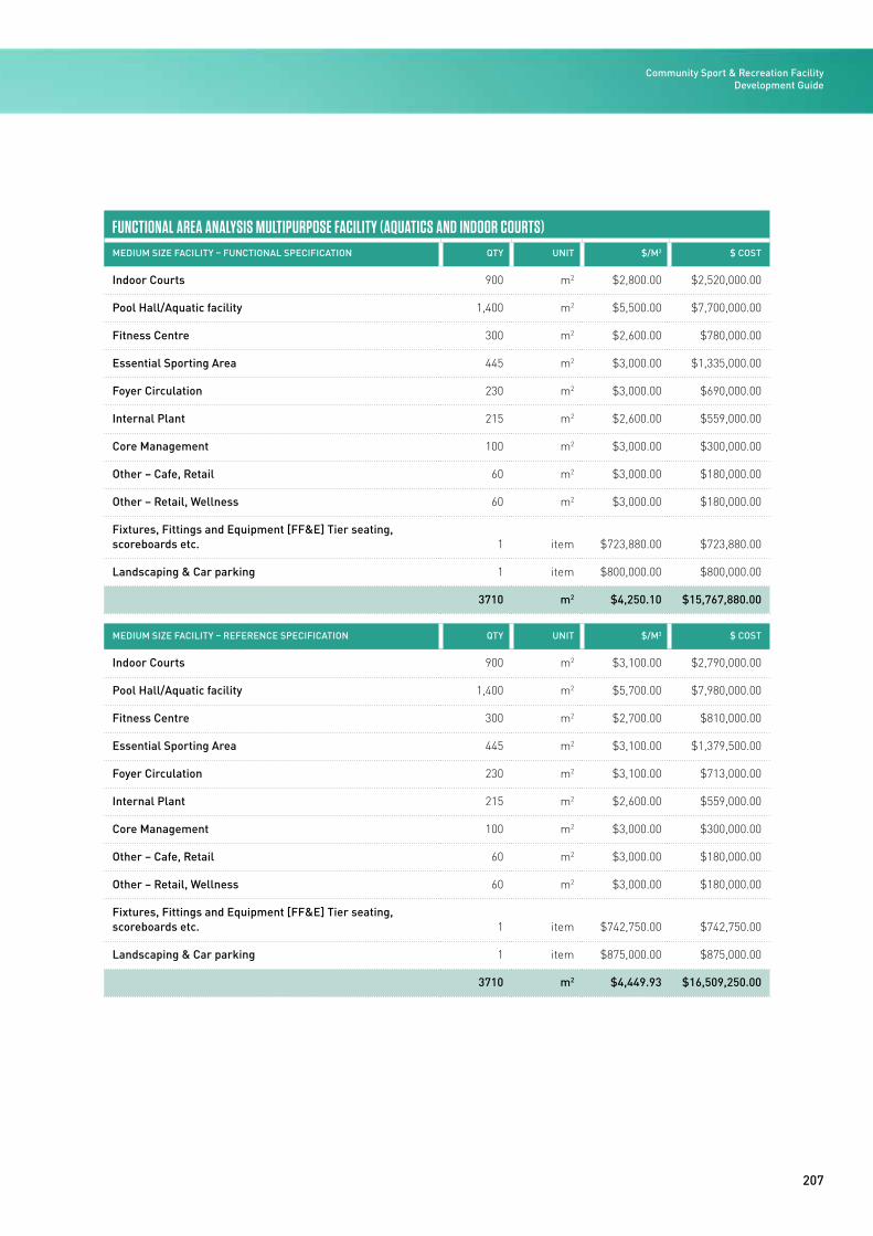
207
FUNCTIONAL AREA ANALYSIS MULTIPURPOSE FACILITY (AQUATICS AND INDOOR COURTS)MEDIUM SIZE FACILITY – FUNCTIONAL SPECIFICATION QTY UNIT $/M2 $ COST
Indoor Courts 900 m2 $2,800.00 $2,520,000.00
Pool Hall/Aquatic facility 1,400 m2 $5,500.00 $7,700,000.00
Fitness Centre 300 m2 $2,600.00 $780,000.00
Essential Sporting Area 445 m2 $3,000.00 $1,335,000.00
Foyer Circulation 230 m2 $3,000.00 $690,000.00
Internal Plant 215 m2 $2,600.00 $559,000.00
Core Management 100 m2 $3,000.00 $300,000.00
Other – Cafe, Retail 60 m2 $3,000.00 $180,000.00
Other – Retail, Wellness 60 m2 $3,000.00 $180,000.00
Fixtures, Fittings and Equipment [FF&E] Tier seating, scoreboards etc. 1 item $723,880.00 $723,880.00
Landscaping & Car parking 1 item $800,000.00 $800,000.00
3710 m2 $4,250.10 $15,767,880.00
MEDIUM SIZE FACILITY – REFERENCE SPECIFICATION QTY UNIT $/M2 $ COST
Indoor Courts 900 m2 $3,100.00 $2,790,000.00
Pool Hall/Aquatic facility 1,400 m2 $5,700.00 $7,980,000.00
Fitness Centre 300 m2 $2,700.00 $810,000.00
Essential Sporting Area 445 m2 $3,100.00 $1,379,500.00
Foyer Circulation 230 m2 $3,100.00 $713,000.00
Internal Plant 215 m2 $2,600.00 $559,000.00
Core Management 100 m2 $3,000.00 $300,000.00
Other – Cafe, Retail 60 m2 $3,000.00 $180,000.00
Other – Retail, Wellness 60 m2 $3,000.00 $180,000.00
Fixtures, Fittings and Equipment [FF&E] Tier seating, scoreboards etc. 1 item $742,750.00 $742,750.00
Landscaping & Car parking 1 item $875,000.00 $875,000.00
3710 m2 $4,449.93 $16,509,250.00
Community Sport & Recreation Facility Development Guide

208
FUNCTIONAL AREA ANALYSIS MULTIPURPOSE FACILITY (AQUATICS AND INDOOR COURTS)
MEDIUM SIZE FACILITY – ENHANCED SPECIFICATION QTY UNIT $/M2 $ COST
Indoor Courts 900 m2 $3,200.00 $2,880,000.00
Pool Hall/Aquatic facility 1,400 m2 $6,100.00 $8,540,000.00
Fitness Centre 300 m2 $2,700.00 $810,000.00
Essential Sporting Area 445 m2 $3,000.00 $1,335,000.00
Foyer Circulation 230 m2 $3,100.00 $713,000.00
Internal Plant 215 m2 $2,600.00 $559,000.00
Core Management 100 m2 $3,000.00 $300,000.00
Other – Cafe, Retail 60 m2 $3,000.00 $180,000.00
Other – Retail, Wellness 60 m2 $3,000.00 $180,000.00
Fixtures, Fittings and Equipment [FF&E] Tier seating, scoreboards etc. 1 item $827,910.00 $827,910.00
Landscaping & Car parking 1 item $925,000.00 $925,000.00
3710 m2 $4,649.57 $17,249,910.00
STAGE 4: BUILD
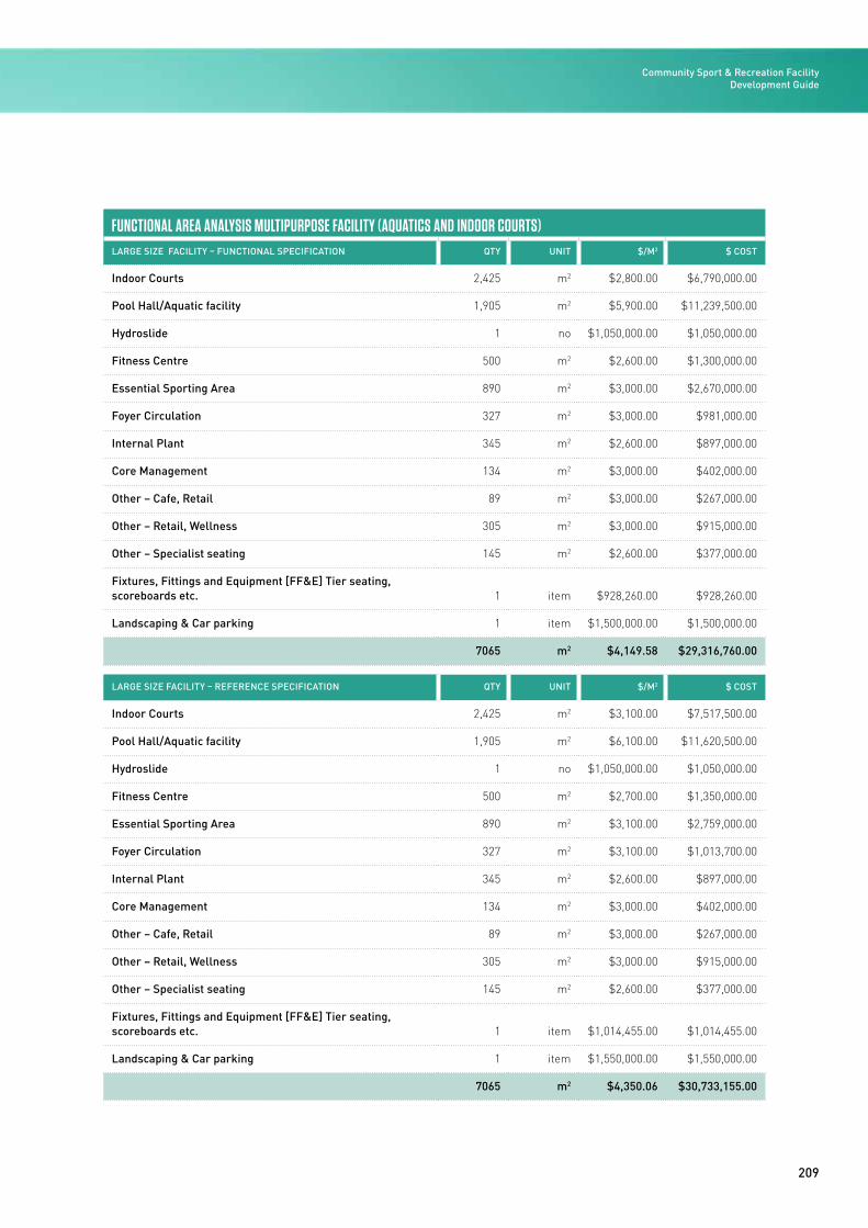
209
FUNCTIONAL AREA ANALYSIS MULTIPURPOSE FACILITY (AQUATICS AND INDOOR COURTS)LARGE SIZE FACILITY – FUNCTIONAL SPECIFICATION QTY UNIT $/M2 $ COST
Indoor Courts 2,425 m2 $2,800.00 $6,790,000.00
Pool Hall/Aquatic facility 1,905 m2 $5,900.00 $11,239,500.00
Hydroslide 1 no $1,050,000.00 $1,050,000.00
Fitness Centre 500 m2 $2,600.00 $1,300,000.00
Essential Sporting Area 890 m2 $3,000.00 $2,670,000.00
Foyer Circulation 327 m2 $3,000.00 $981,000.00
Internal Plant 345 m2 $2,600.00 $897,000.00
Core Management 134 m2 $3,000.00 $402,000.00
Other – Cafe, Retail 89 m2 $3,000.00 $267,000.00
Other – Retail, Wellness 305 m2 $3,000.00 $915,000.00
Other – Specialist seating 145 m2 $2,600.00 $377,000.00
Fixtures, Fittings and Equipment [FF&E] Tier seating, scoreboards etc. 1 item $928,260.00 $928,260.00
Landscaping & Car parking 1 item $1,500,000.00 $1,500,000.00
7065 m2 $4,149.58 $29,316,760.00
LARGE SIZE FACILITY – REFERENCE SPECIFICATION QTY UNIT $/M2 $ COST
Indoor Courts 2,425 m2 $3,100.00 $7,517,500.00
Pool Hall/Aquatic facility 1,905 m2 $6,100.00 $11,620,500.00
Hydroslide 1 no $1,050,000.00 $1,050,000.00
Fitness Centre 500 m2 $2,700.00 $1,350,000.00
Essential Sporting Area 890 m2 $3,100.00 $2,759,000.00
Foyer Circulation 327 m2 $3,100.00 $1,013,700.00
Internal Plant 345 m2 $2,600.00 $897,000.00
Core Management 134 m2 $3,000.00 $402,000.00
Other – Cafe, Retail 89 m2 $3,000.00 $267,000.00
Other – Retail, Wellness 305 m2 $3,000.00 $915,000.00
Other – Specialist seating 145 m2 $2,600.00 $377,000.00
Fixtures, Fittings and Equipment [FF&E] Tier seating, scoreboards etc. 1 item $1,014,455.00 $1,014,455.00
Landscaping & Car parking 1 item $1,550,000.00 $1,550,000.00
7065 m2 $4,350.06 $30,733,155.00
Community Sport & Recreation Facility Development Guide
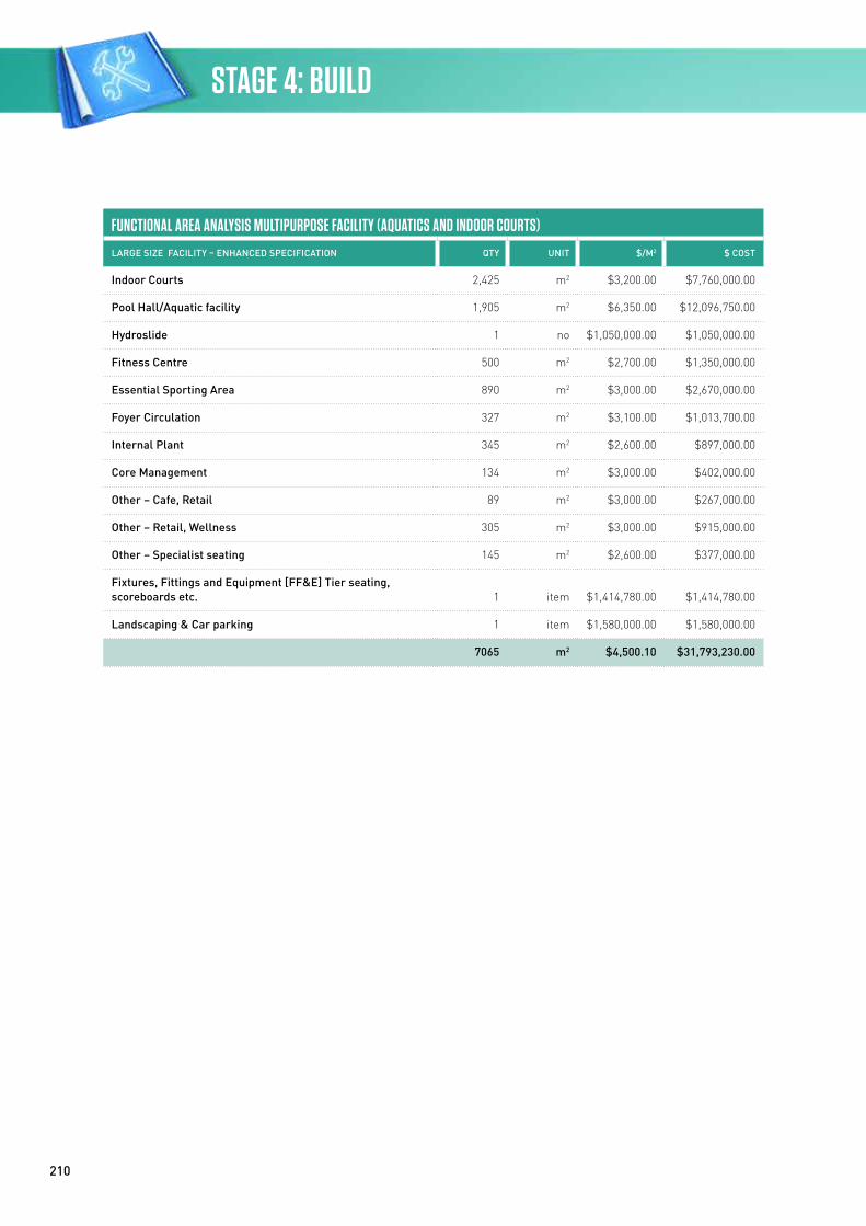
210
FUNCTIONAL AREA ANALYSIS MULTIPURPOSE FACILITY (AQUATICS AND INDOOR COURTS)
LARGE SIZE FACILITY – ENHANCED SPECIFICATION QTY UNIT $/M2 $ COST
Indoor Courts 2,425 m2 $3,200.00 $7,760,000.00
Pool Hall/Aquatic facility 1,905 m2 $6,350.00 $12,096,750.00
Hydroslide 1 no $1,050,000.00 $1,050,000.00
Fitness Centre 500 m2 $2,700.00 $1,350,000.00
Essential Sporting Area 890 m2 $3,000.00 $2,670,000.00
Foyer Circulation 327 m2 $3,100.00 $1,013,700.00
Internal Plant 345 m2 $2,600.00 $897,000.00
Core Management 134 m2 $3,000.00 $402,000.00
Other – Cafe, Retail 89 m2 $3,000.00 $267,000.00
Other – Retail, Wellness 305 m2 $3,000.00 $915,000.00
Other – Specialist seating 145 m2 $2,600.00 $377,000.00
Fixtures, Fittings and Equipment [FF&E] Tier seating, scoreboards etc. 1 item $1,414,780.00 $1,414,780.00
Landscaping & Car parking 1 item $1,580,000.00 $1,580,000.00
7065 m2 $4,500.10 $31,793,230.00
STAGE 4: BUILD
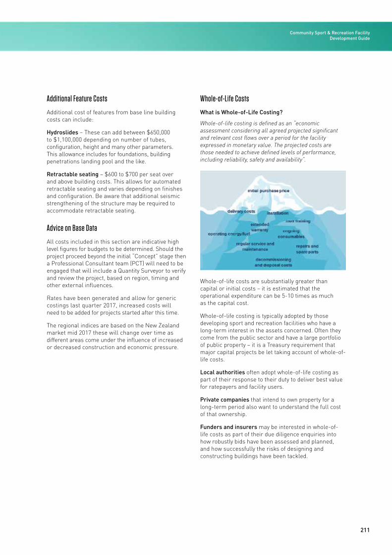
211
Additional Feature Costs
Additional cost of features from base line building costs can include:
Hydroslides – These can add between $650,000 to $1,100,000 depending on number of tubes, configuration, height and many other parameters. This allowance includes for foundations, building penetrations landing pool and the like.
Retractable seating – $600 to $700 per seat over and above building costs. This allows for automated retractable seating and varies depending on finishes and configuration. Be aware that additional seismic strengthening of the structure may be required to accommodate retractable seating.
Advice on Base Data
All costs included in this section are indicative high level figures for budgets to be determined. Should the project proceed beyond the initial “Concept” stage then a Professional Consultant team (PCT) will need to be engaged that will include a Quantity Surveyor to verify and review the project, based on region, timing and other external influences.
Rates have been generated and allow for generic costings last quarter 2017, increased costs will need to be added for projects started after this time.
The regional indices are based on the New Zealand market mid 2017 these will change over time as different areas come under the influence of increased or decreased construction and economic pressure.
Whole-of-Life Costs
What is Whole-of-Life Costing?
Whole-of-life costing is defined as an “economic assessment considering all agreed projected significant and relevant cost flows over a period for the facility expressed in monetary value. The projected costs are those needed to achieve defined levels of performance, including reliability, safety and availability”.
Whole-of-life costs are substantially greater than capital or initial costs – it is estimated that the operational expenditure can be 5-10 times as much as the capital cost.
Whole-of-life costing is typically adopted by those developing sport and recreation facilities who have a long-term interest in the assets concerned. Often they come from the public sector and have a large portfolio of public property – it is a Treasury requirement that major capital projects be let taking account of whole-of-life costs.
Local authorities often adopt whole-of-life costing as part of their response to their duty to deliver best value for ratepayers and facility users.
Private companies that intend to own property for a long-term period also want to understand the full cost of that ownership.
Funders and insurers may be interested in whole-of-life costs as part of their due diligence enquiries into how robustly bids have been assessed and planned, and how successfully the risks of designing and constructing buildings have been tackled.
Community Sport & Recreation Facility Development Guide
212
Demand for those developing community facilities and who want to consider whole-of-life costing is causing designers, contractors and manufacturers to develop their understanding of whole-of-life costs as applied to specific projects or their generic services.
What are the Benefits of Whole-of-Life Costing?
• Encourages analysis of business needs and communication of these to the project team
• Optimises the total cost of ownership/occupation by balancing initial capital and running costs
• Ensures risk and cost analysis of loss of functional performance due to failure or inadequate maintenance
• Promotes realistic budgeting for operation, maintenance and repairs
• Encourages discussion and recording of decisions about the durability of materials and components at the outset of the project
• Provides data on actual performance and operation compared with predicted performance for use in future planning and benchmarking.
STAGE 4: BUILD
Community Sport & Recreation Facility Development Guide / 2016
STAGE 5
214
STAGE 5: OPERATE
Well developed operations and management practices of sport and recreation facilities are of critical importance for management, operational planning and financial planning processes, but are often overlooked by facility operators who have little or no experience in maintaining sport and recreation assets.
Any community sport and recreation facility is a significant investment in infrastructure, and good management practices in terms of the asset are essential to ensure the longevity of the investment.
This section outlines the process for securing the right operators and management arrangements and contains key information about operating the reference facility, including indicative costs. For additional information and detail consider the following Sport NZ and NZRA resources:
Facility Management Manual www.sportnz.org.nz/facilitymanagementmanual
Aquatic Facility Guidelines www.sportnz.org.nz/aquaticfacilityguidelines
Procurement of OperatorsThe procurement of an operator is outlined below and covers:
• The procurement process
• Contracting type
• Selection of operator
• Specific contract mechanisms
• Key requirements and documents
• Evaluation criteria (selection criteria and weightings).
Operator Procurement Process
Typically, local government will operate, maintain and service the facilities, but there may be some cases where this is not applicable. In these cases the procurement of an operator is required. Operator procurement follows a similar process to the contractor procurement process in Section 4.
Contracting Type
The procurement strategy will also outline the preferred operational contracting type. The preferred contracting type establishes the framework for the life-cycle delivery of the project. There are several delivery models available, which represent varying degrees of complexity, risk, innovation, client involvement and programme influence. This is summarised for operations and maintenance in the following delivery model summary table.
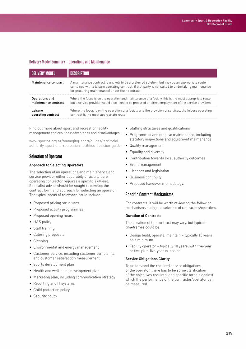
215
Community Sport & Recreation Facility Development Guide
Delivery Model Summary – Operations and Maintenance
DELIVERY MODEL DESCRIPTION
Maintenance contract A maintenance contract is unlikely to be a preferred solution, but may be an appropriate route if combined with a leisure operating contract, if that party is not suited to undertaking maintenance (or procuring maintenance) under their contract
Operations and maintenance contract
Where the focus is on the operation and maintenance of a facility, this is the most appropriate route, but a service provider would also need to be procured or direct employment of the service providers
Leisure operating contract
Where the focus is on the operation of a facility and the provision of services, the leisure operating contract is the most appropriate route
Find out more about sport and recreation facility management choices, their advantages and disadvantages:
www.sportnz.org.nz/managing-sport/guides/territorial-authority-sport-and-recreation-facilities-decision-guide
Selection of Operator
Approach to Selecting Operators
The selection of an operations and maintenance and service provider either separately or as a leisure operating contractor requires a specific skill-set. Specialist advice should be sought to develop the contract form and approach for selecting an operator. The typical areas of relevance could include:
• Proposed pricing structures
• Proposed activity programmes
• Proposed opening hours
• H&S policy
• Staff training
• Catering proposals
• Cleaning
• Environmental and energy management
• Customer service, including customer complaints and customer satisfaction measurement
• Sports development plan
• Health and well-being development plan
• Marketing plan, including communication strategy
• Reporting and IT systems
• Child protection policy
• Security policy
• Staffing structures and qualifications
• Programmed and reactive maintenance, including statutory inspections and equipment maintenance
• Quality management
• Equality and diversity
• Contribution towards local authority outcomes
• Event management
• Licences and legislation
• Business continuity
• Proposed handover methodology.
Specific Contract Mechanisms
For contracts, it will be worth reviewing the following mechanisms during the selection of contractors/operators.
Duration of Contracts
The duration of the contract may vary, but typical timeframes could be:
• Design build, operate, maintain – typically 15 years as a minimum
• Facility operator – typically 10 years, with five-year or five-plus-five-year extension.
Service Obligations Clarity
To understand the required service obligations of the operator, there has to be some clarification of the objectives required, and specific targets against which the performance of the contractor/operator can be measured.
216
STAGE 5: OPERATE
REQUIREMENT EXAMPLE
Service delivery requirements
Relating to sports development/health and well-being plans/customer care/reporting/pricing/programming/opening hours
Facility management requirements
Cleaning/maintenance/lighting/heating/staffing/equipment
Service Obligations and Audit Function Requirement
Specified service obligations will need to be audited to make sure the requirements are being met to a suitable standard and, if not, identify the remediation that will be required to meet the obligations. This may be through in-house auditing or outsourced to a third party.
Loss of Revenue
Under the conditional basis of operating and maintaining the facility, it may be prudent to consider lost income due to unforeseen circumstances. This can include income lost due to insufficient customers, for example, or even lost income due to the particular position of the facility.
Utilities’ Consumption and Utilities Tariff
A utilities benchmarking mechanism is often included in legal schedules to provide a framework within which a contractor can price for utilities. The standard position is that the contractor takes responsibility for consumption risk, with the local authority taking risks associated with fluctuations in tariff.
Key Requirements and Documents
Lease Agreement
In both forms of contract a lease is ultimately used, although a licence is granted to the contractor during the works period of the design, build, operate and maintain contract. The granting of a lease means the contractor will be ‘in occupation’ of the facilities. The lease does not contain any substantive provisions (for instance in relation to repairs/maintenance/insurance etc). These provisions are dealt with in the main contract and the lease refers back to the main contract on such issues so as to avoid conflict between the documents.
Safety in Design
SiD is the integration of hazard identification, risk assessment and control methods in the design process to eliminate or minimise risks to H&S throughout the construction and life of the element being designed.
All design documentation prepared for the project works shall be subject to this SiD process. Each design manager retains the primary responsibility for ensuring that the design work packages have been prepared in compliance with this procedure. This is also covered in more detail in Section 3.
Facility Management Plan
A facility management plan ensures that the essential requirements have been covered. Examples include but are not limited to:
• Cleaning
• Maintenance
• Lighting
• Heating
• Staffing
• Equipment.
Operations and Maintenance Plan
In an aquatic facility, an operation and maintenance plan is a critical component of maintaining H&S. Operation and maintenance lapses can be critical contributors to disease outbreaks and injuries. The facility operation and maintenance plan lays the foundation for operational improvement by containing requirements for:
• Closing and reopening for long- and short-term closures
• Comprehensive plans for preventive maintenance and equipment inventory and the development of an operations manual to be maintained at the facility
• Reducing and mitigating excessive glare and reflection on the pool surface through design of and adjustments to windows and lighting equipment
• Comprehensive daily records of pool operation and maintenance and of operational items inspected daily.
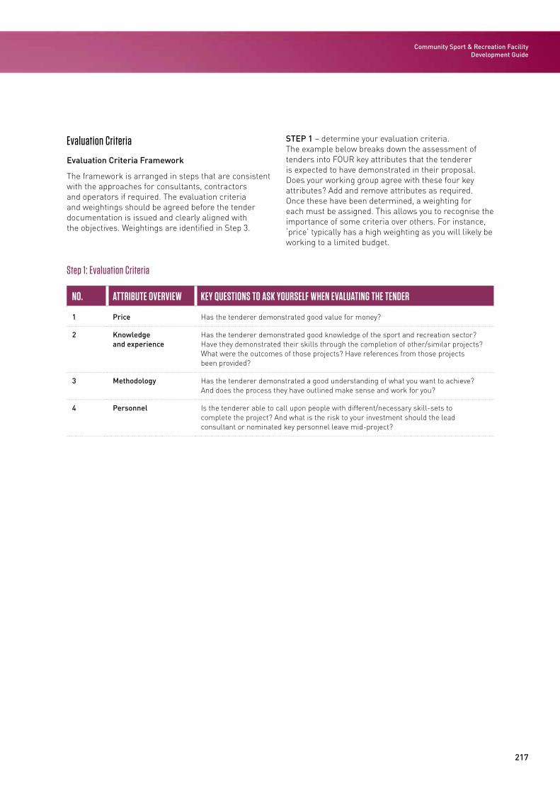
217
Community Sport & Recreation Facility Development Guide
Evaluation Criteria
Evaluation Criteria Framework
The framework is arranged in steps that are consistent with the approaches for consultants, contractors and operators if required. The evaluation criteria and weightings should be agreed before the tender documentation is issued and clearly aligned with the objectives. Weightings are identified in Step 3.
STEP 1 – determine your evaluation criteria. The example below breaks down the assessment of tenders into FOUR key attributes that the tenderer is expected to have demonstrated in their proposal. Does your working group agree with these four key attributes? Add and remove attributes as required. Once these have been determined, a weighting for each must be assigned. This allows you to recognise the importance of some criteria over others. For instance, ‘price’ typically has a high weighting as you will likely be working to a limited budget.
Step 1: Evaluation Criteria
NO. ATTRIBUTE OVERVIEW KEY QUESTIONS TO ASK YOURSELF WHEN EVALUATING THE TENDER
1 Price Has the tenderer demonstrated good value for money?
2 Knowledge and experience
Has the tenderer demonstrated good knowledge of the sport and recreation sector? Have they demonstrated their skills through the completion of other/similar projects? What were the outcomes of those projects? Have references from those projects been provided?
3 Methodology Has the tenderer demonstrated a good understanding of what you want to achieve? And does the process they have outlined make sense and work for you?
4 Personnel Is the tenderer able to call upon people with different/necessary skill-sets to complete the project? And what is the risk to your investment should the lead consultant or nominated key personnel leave mid-project?
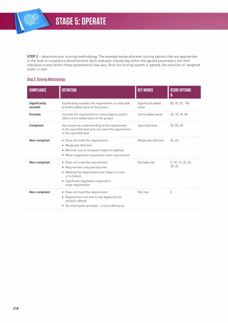
218
STAGE 5: OPERATE
STEP 2 – determine your scoring methodology. The example below allocates scoring options that are appropriate to the level of compliance demonstrated. Each evaluator should stay within the agreed parameters, but their individual scores (within those parameters) may vary. Once the scoring system is agreed, the selection of ‘weighted totals’ is next.
Step 2: Scoring Methodology
COMPLIANCE DEFINITION KEY WORDS SCORE OPTIONS%
Significantly exceeds
Significantly exceeds the requirement in a way that provides added value to the project
Significant added value
85, 90, 95, 100
Exceeds Exceeds the requirement in some aspects and/or offers some added value to the project
Some added value 65, 70, 75, 80
Compliant Has shown an understanding of the requirement to the specified level and can meet the requirement to the specified level
Specified level 50, 55, 60
Non-compliant • Does not meet the requirement
• Marginally deficient
• Minimal cost or schedule impact to address
• Minor negotiation required to meet requirement
Marginally deficient 40, 45
Non-compliant • Does not meet the requirement
• Requirement only partially met
• Meeting the requirement will impact on cost or schedule
• Significant negotiation required to meet requirement
Partially met 5, 10, 15, 20, 25, 30, 35
Non-compliant • Does not meet the requirement
• Requirement not met to any degree by the solution offered
• No information provided – critical deficiency
Not met 0
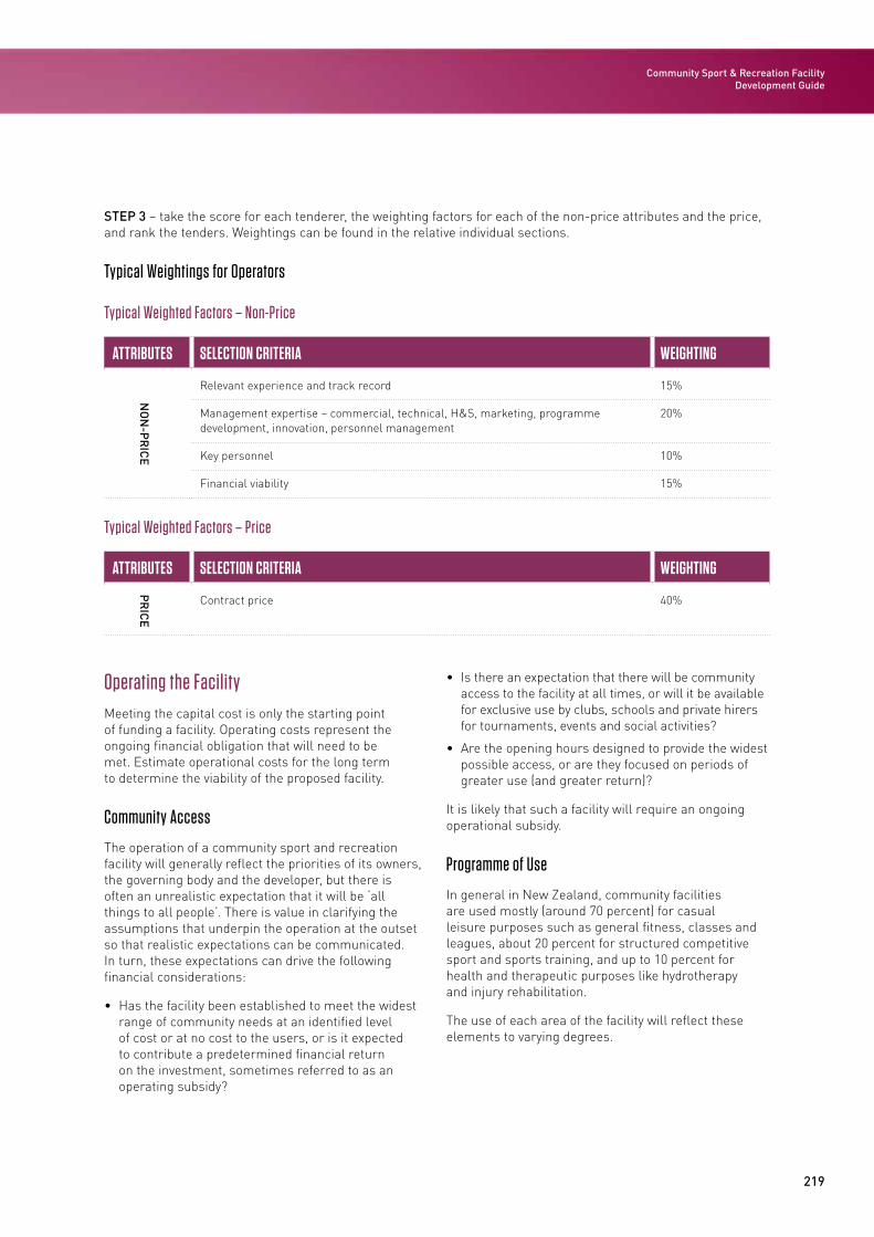
219
Community Sport & Recreation Facility Development Guide
STEP 3 – take the score for each tenderer, the weighting factors for each of the non-price attributes and the price, and rank the tenders. Weightings can be found in the relative individual sections.
Typical Weightings for Operators
Typical Weighted Factors – Non-Price
ATTRIBUTES SELECTION CRITERIA WEIGHTING
NO
N-P
RIC
E
Relevant experience and track record 15%
Management expertise – commercial, technical, H&S, marketing, programme development, innovation, personnel management
20%
Key personnel 10%
Financial viability 15%
Typical Weighted Factors – Price
ATTRIBUTES SELECTION CRITERIA WEIGHTING
PR
ICE
Contract price 40%
Operating the FacilityMeeting the capital cost is only the starting point of funding a facility. Operating costs represent the ongoing financial obligation that will need to be met. Estimate operational costs for the long term to determine the viability of the proposed facility.
Community Access
The operation of a community sport and recreation facility will generally reflect the priorities of its owners, the governing body and the developer, but there is often an unrealistic expectation that it will be ‘all things to all people’. There is value in clarifying the assumptions that underpin the operation at the outset so that realistic expectations can be communicated. In turn, these expectations can drive the following financial considerations:
• Has the facility been established to meet the widest range of community needs at an identified level of cost or at no cost to the users, or is it expected to contribute a predetermined financial return on the investment, sometimes referred to as an operating subsidy?
• Is there an expectation that there will be community access to the facility at all times, or will it be available for exclusive use by clubs, schools and private hirers for tournaments, events and social activities?
• Are the opening hours designed to provide the widest possible access, or are they focused on periods of greater use (and greater return)?
It is likely that such a facility will require an ongoing operational subsidy.
Programme of Use
In general in New Zealand, community facilities are used mostly (around 70 percent) for casual leisure purposes such as general fitness, classes and leagues, about 20 percent for structured competitive sport and sports training, and up to 10 percent for health and therapeutic purposes like hydrotherapy and injury rehabilitation.
The use of each area of the facility will reflect these elements to varying degrees.
220
STAGE 5: OPERATE
In the aquatics area, most hours are likely to be committed to casual use by families and individuals seeking an enjoyable recreational and leisure experience or some healthy physical activity. At peak times (usually weekdays in the late afternoon and early evening), there is likely to be competing demand for water space from aquatic sports clubs training or competition, swimming lessons, after-school care and lane swimming by individuals.
Daytime hours provide an opportunity for more targeted programming opportunities such as group activities (aquarobics classes, older adults, water safety, school groups) and swimming lessons.
Children’s programmes (holiday programmes, evening ‘fun’ sessions, after-school care) may also be major users at specific times.
Sports court areas are likely to have major use in the evening peak times by local sports organisations (especially netball, basketball, volleyball and tennis) and in the day by school groups if they are without their own facilities. The challenge for management is to fill the off-peak times as much as possible, and a major user may be sports leagues for those who prefer to participate in a more casual, less structured manner than those run by formal sporting bodies. Other activities may be group exercise classes, children’s classes, fitness circuits, prescribed health programmes, eg, ‘green prescription’, and sports academies’ training activities.
The use of the fitness centre is likely to follow a more traditional pattern, although sessions for older people, sports clubs, injury rehabilitation, weight loss and young athletes may be a feature depending on the local demographics, need and demand. Group fitness classes, including activities targeting flexibility and general-well-being, are likely to be attractive to many if space is available.
Potential Facility Management Arrangements
Local authorities in New Zealand have a history of investing in sport and recreation facilities in their communities to achieve community outcomes. Individual councils have tended to make decisions about how best to structure the management of these facilities based on varying levels of knowledge and differing levels of analysis.
Sport NZ commissioned a report published in 2013 to provide assistance in making these decisions. This report provides an overview of the range of
management choices, both current and potential. It outlines the key characteristics of each of the different models and their advantages and disadvantages, drawn from research conducted with a range of New Zealand local authorities and private providers and relevant Australian and UK research.
In New Zealand, there are currently six main management models for council sport and recreation facilities:
• In-house management
• Contracted or leased to a private provider
• Contracted or leased to a community trust or committee
• A council-controlled organisation
• A mixed management model, where the council chooses to have a combination of any or all of the above models
• A hands-off model, where the council supports and facilitates a local community to develop its own facilities.
In New Zealand, the great majority of facilities are managed in-house (at least 75 percent) while commercial operators manage 15-20 percent.
Where there is a major investment in the development of a facility by a private contractor, that contractor is likely to have an opportunity to manage the facility for a time period sufficient to generate a reasonable return on their investment.
Facility Indicative/Generic Income
Estimating the income of a facility requires making a number of assumptions about aspects including:
• Population numbers likely to produce facility users
• Local competition for sport and recreation activity
• Funding policy and pricing strategy
• Priorities for facility use and community demographics profile
• Arrangements with clubs and other hirers
• Community expectations.
In general, the major income areas for a facility are likely to be swimming lessons, health and fitness centre memberships and staff-run programmes such as children’s activities, group exercise and ‘social’ sports leagues.
221
Community Sport & Recreation Facility Development Guide
Income from hire-to-clubs and other community-based users does not usually contribute as significantly, and where activities such as LTS are offered to other providers, the return on operating costs is likely to be lower.
Retail, catering and vending are also potential income streams, although generally it is accepted that a fully catered café may require in excess of 240,000-300,000 visits per annum to be profitable. As a guideline, it may be assumed that a well run facility could achieve five to seven visits per head of population annually.
Facility Indicative/Generic Costs/Expenditure
The major costs in operating a community sport and recreation facility are related to staffing. In the main these are fixed costs, but there will be a variable element (such as casual lifeguard cover) linked to variations in the pool programme, and programme leader costs (such as for swimming or aerobics instructors and referees). A stand-alone facility will have proportionally higher staff costs than a multi-sports centre due to the limited ability to share resources. In New Zealand, the average staffing cost is as high as 87 percent of the income generated.
The second-largest operational cost is utilities. This is mainly fixed because the water and air need to be treated and heated, irrespective of usage levels and dependent on the efficiency and effectiveness of the heating and ventilation plant and equipment installed. Operational policies will also impact on utility costs, for example, by varying bather load, use of showers, backwashing filters and loss of water through leaks or evaporation.
An aquatic centre’s average operating cost is over $1,200 per sqm of water space, while revenue is around $750 per sqm of water space.
Indicative Operating Budgets for Facility Types
The following are indicative budgets for the three facilities outlined in Section 1 for the linear facility model (small, medium and large). The detail of these budgets will be impacted by a significant number of issues including population, pricing, facility management, costs of services and utilities, priorities for use and local competition.
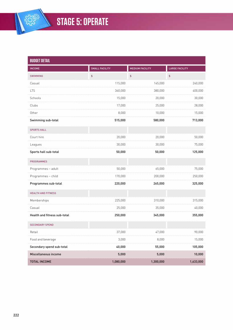
222
STAGE 5: OPERATE
BUDGET DETAIL
INCOME SMALL FACILITY MEDIUM FACILITY LARGE FACILITY
SWIMMING $ $ $
Casual 115,000 145,000 240,000
LTS 360,000 380,000 400,000
Schools 15,000 20,000 30,000
Clubs 17,000 25,000 28,000
Other 8,000 10,000 15,000
Swimming sub-total 515,000 580,000 713,000
SPORTS HALL
Court hire 20,000 20,000 50,000
Leagues 30,000 30,000 75,000
Sports hall sub-total 50,000 50,000 125,000
PROGRAMMES
Programmes – adult 50,000 65,000 75,000
Programmes – child 170,000 200,000 250,000
Programmes sub-total 220,000 265,000 325,000
HEALTH AND FITNESS
Memberships 225,000 310,000 315,000
Casual 25,000 35,000 40,000
Health and fitness sub-total 250,000 345,000 355,000
SECONDARY SPEND
Retail 37,000 47,000 90,000
Food and beverage 3,000 8,000 15,000
Secondary spend sub-total 40,000 55,000 105,000
Miscellaneous income 5,000 5,000 10,000
TOTAL INCOME 1,080,000 1,300,000 1,633,000
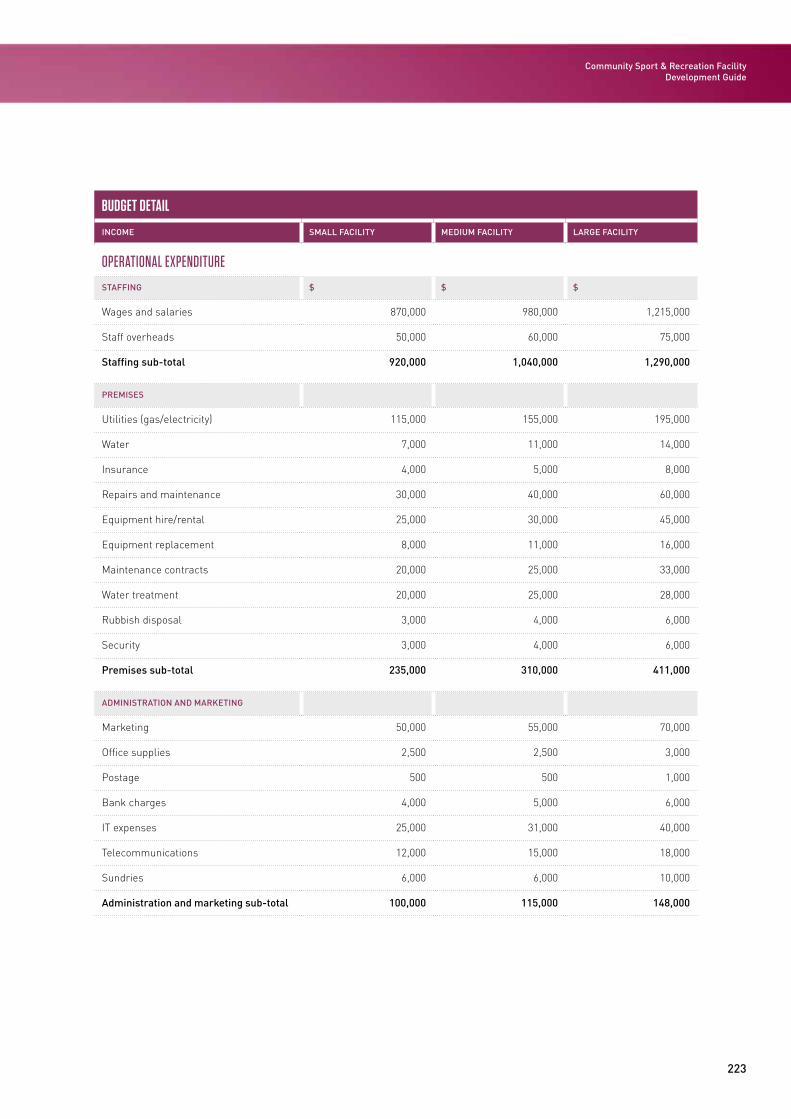
223
Community Sport & Recreation Facility Development Guide
BUDGET DETAIL
INCOME SMALL FACILITY MEDIUM FACILITY LARGE FACILITY
OPERATIONAL EXPENDITURE
STAFFING $ $ $
Wages and salaries 870,000 980,000 1,215,000
Staff overheads 50,000 60,000 75,000
Staffing sub-total 920,000 1,040,000 1,290,000
PREMISES
Utilities (gas/electricity) 115,000 155,000 195,000
Water 7,000 11,000 14,000
Insurance 4,000 5,000 8,000
Repairs and maintenance 30,000 40,000 60,000
Equipment hire/rental 25,000 30,000 45,000
Equipment replacement 8,000 11,000 16,000
Maintenance contracts 20,000 25,000 33,000
Water treatment 20,000 25,000 28,000
Rubbish disposal 3,000 4,000 6,000
Security 3,000 4,000 6,000
Premises sub-total 235,000 310,000 411,000
ADMINISTRATION AND MARKETING
Marketing 50,000 55,000 70,000
Office supplies 2,500 2,500 3,000
Postage 500 500 1,000
Bank charges 4,000 5,000 6,000
IT expenses 25,000 31,000 40,000
Telecommunications 12,000 15,000 18,000
Sundries 6,000 6,000 10,000
Administration and marketing sub-total 100,000 115,000 148,000
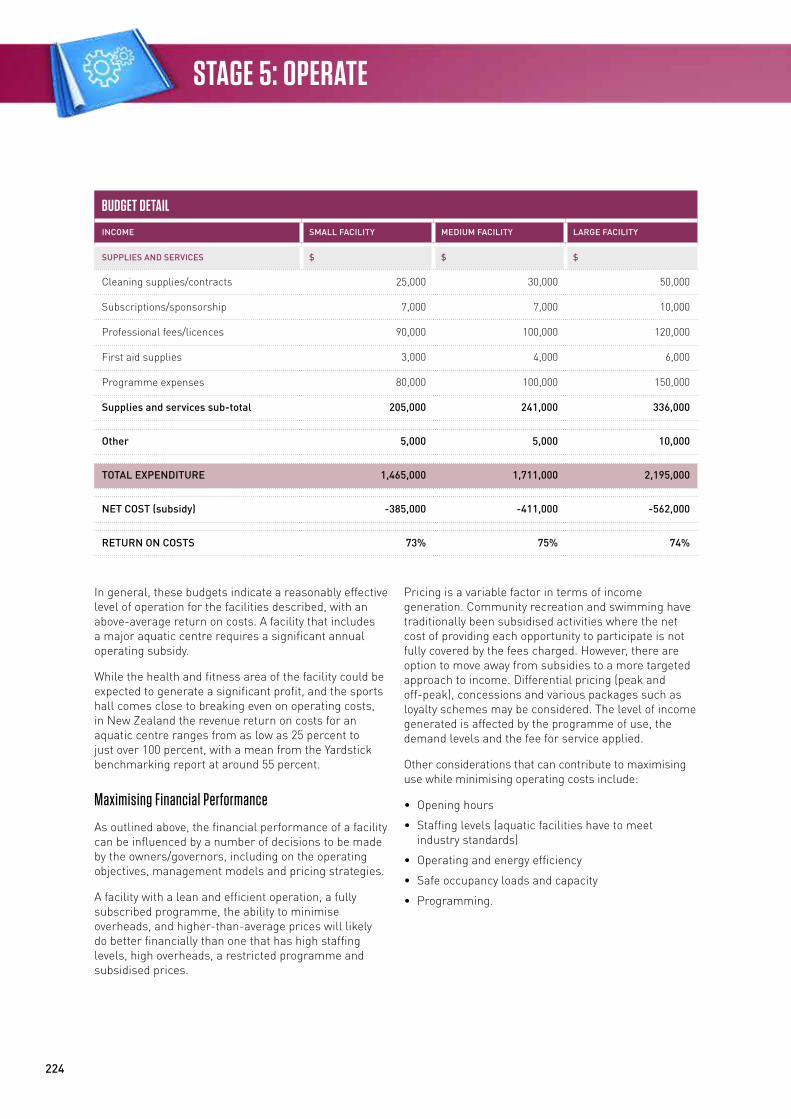
224
STAGE 5: OPERATE
BUDGET DETAIL
INCOME SMALL FACILITY MEDIUM FACILITY LARGE FACILITY
SUPPLIES AND SERVICES $ $ $
Cleaning supplies/contracts 25,000 30,000 50,000
Subscriptions/sponsorship 7,000 7,000 10,000
Professional fees/licences 90,000 100,000 120,000
First aid supplies 3,000 4,000 6,000
Programme expenses 80,000 100,000 150,000
Supplies and services sub-total 205,000 241,000 336,000
Other 5,000 5,000 10,000
TOTAL EXPENDITURE 1,465,000 1,711,000 2,195,000
NET COST (subsidy) -385,000 -411,000 -562,000
RETURN ON COSTS 73% 75% 74%
In general, these budgets indicate a reasonably effective level of operation for the facilities described, with an above-average return on costs. A facility that includes a major aquatic centre requires a significant annual operating subsidy.
While the health and fitness area of the facility could be expected to generate a significant profit, and the sports hall comes close to breaking even on operating costs, in New Zealand the revenue return on costs for an aquatic centre ranges from as low as 25 percent to just over 100 percent, with a mean from the Yardstick benchmarking report at around 55 percent.
Maximising Financial Performance
As outlined above, the financial performance of a facility can be influenced by a number of decisions to be made by the owners/governors, including on the operating objectives, management models and pricing strategies.
A facility with a lean and efficient operation, a fully subscribed programme, the ability to minimise overheads, and higher-than-average prices will likely do better financially than one that has high staffing levels, high overheads, a restricted programme and subsidised prices.
Pricing is a variable factor in terms of income generation. Community recreation and swimming have traditionally been subsidised activities where the net cost of providing each opportunity to participate is not fully covered by the fees charged. However, there are option to move away from subsidies to a more targeted approach to income. Differential pricing (peak and off-peak), concessions and various packages such as loyalty schemes may be considered. The level of income generated is affected by the programme of use, the demand levels and the fee for service applied.
Other considerations that can contribute to maximising use while minimising operating costs include:
• Opening hours
• Staffing levels (aquatic facilities have to meet industry standards)
• Operating and energy efficiency
• Safe occupancy loads and capacity
• Programming.
225
Community Sport & Recreation Facility Development Guide
Staffing levels and remuneration should be considered carefully and well managed without compromising requisite levels to maintain a safe and user-friendly experience. Active programming with a focus on creating revenue, particularly in off-peak times, can contribute significantly to an improved return on operating costs.
The design of the pool and the efficiency of the plant can also impact on running costs. In many cases additional capital expenditure on the most efficient plant, fittings and equipment can achieve savings in operating costs over the life of the facility. A robust repair and maintenance programme is needed to ensure that plant and equipment are working efficiently. Also, equipment and facility breakages are repaired quickly so as to not lessen the customer experience.
Revenue Stream Opportunities
The key to maximising revenue is to add value to the customer experience and in turn to increase the visitor spend. For example, a swim school enrolment provides the opportunity to market swimwear, towels, goggles and programme-related materials such as music and books. In addition, a presence in the swim school lends itself to marketing holiday programmes, other children’s programmes and other sports.
The same principle obviously applies to adult programmes. Well managed social media provide an opportunity to expand the market for a facility’s services far beyond that which is available through traditional advertising media.
The current trends in sports participation towards short-term, less-structured competitions entered by teams formed in workplaces, social settings, family or whanau also provide extra opportunities for facility revenue. Such competitions can include traditional indoor sports (netball, basketball and volleyball) and less traditional sports (indoor touch and dodgeball). Where these are delivered to a high standard of organisation and officiating they can prove more attractive than traditional leagues and dramatically improve revenue in times of otherwise low demand.
Operational Health and Safety Requirements
A community sport and recreation facility has the potential to have a number of H&S risks associated with the nature of the physical environment and how it gets used – deep water, high levels of possibly stressful physical activity often involving large groups of people, and potentially hazardous equipment. H&S is therefore a primary consideration in the operation and management of such a facility.
The majority of these requirements are outlined in New Zealand H&S legislation, and there are potentially severe penalties for failing to conform with them.
The recreation industry through the NZRA and Water Safety New Zealand also administers a voluntary minimum standard for H&S through the PoolSafe scheme, and offers management guidelines for swimming pools and recreation centres.
The New Zealand Accident Compensation Corporation also offers an accreditation scheme that provides an additional external measure of performance in relation to H&S.
Community Sport & Recreation Facility Development Guide / 2016
STAGE 6
227
Community Sport & Recreation Facility Development GuideSTAGE 6: IMPROVE
Building PerformanceAs modern building becomes more technology focused and ‘intelligent’, with specific requirements in design, construction, maintenance and operation, a process is required that aligns the interests of those who design and construct an asset with the interests of those who use and manage it. It aims to improve client and user experiences, with reduced re-visits, and to give a product that meets and performs to client expectations.
The Soft Landings process helps to solve the performance gap between design intentions and operational outcomes. This performance gap can emerge at any stage in a project:
• At inception and briefing, where ambitions and requirements are set but may not be informed by experience and feedback from other projects
• At design, where specific performance targets are set and regulatory compliance achieved, but those targets are neither re-visited nor reality-checked during detailed design
• During construction, where budget shortfalls may compromise the best of intentions, and variations are made to the building and its technical systems that change how the building will be used
• During handover, when commissioning and end-user training may be rushed or abandoned to meet deadlines
• During initial occupation, where not enough support is available to occupants and the managers to ensure the building is set up for the long term.
Soft Landings provides a step-by-step process for clients and their project teams to follow in order to avoid these pitfalls and deliver a better-performing product. It aims to create virtuous circles for all. Whether your project is attempting to achieve exemplary environmental standards or is a simple extension or retrofit of an existing building, the Soft Landings culture can be applied to ensure outcomes match the client’s intentions.
The Soft Landings process is designed to give clients and their project teams a process to follow that will lead to a better chance of success. It is a change of culture as much as it is a change of process. Everyone involved has to share the ambition, and share roles and responsibilities, to make buildings tread more lightly on the earth and provide the right internal environments to foster occupant well-being and productivity.
Soft Landings requires clients to appoint designers and contractors who stay involved with their new buildings beyond practical completion and into the critical initial periods of occupation. This will assist building managers during the first months of operation, help to fine-tune and de-bug the systems, and ensure the occupiers understand how to control and best use what they have been given. This is followed by a longer, less intensive period of aftercare lasting for up to three years, to monitor energy use and occupant satisfaction, and to check on the operation of systems that might need seasonal fine-tuning. At the end of three years a buildings’ steady performance can be fairly judged against the targets set at design, and any discrepancies accounted for with the appropriate modifications made for optimisation.
This extended duty of care requires Soft Landings to be considered at the outset and embedded in all client requirements and design decisions. It also needs to be adopted by the contractor so that good intentions are not unnecessarily sacrificed for reasons of cost or time.
The Soft Landings process includes the following key five stages:
• Inception and briefing
• Design development and review
• Pre-handover
• Commissioning
• Initial aftercare
• Years one to three extended aftercare and post-occupancy evaluation (POE).
228
STAGE 6: IMPROVE
Post-Occupancy EvaluationPOE involves the systematic evaluation of opinions about buildings in use from the perspectives of the people who plan, design, build, use, own, manage and operate them. A POE assesses how well buildings match users’ needs, and identifies ways to improve building design, performance and fitness for purpose. POE is an essential component of a continuous improvement process. POEs can be undertaken at any time in the life of a facility. They are often undertaken within a few months of commencing operation or after one or two years of operation. A multi-disciplinary team of relevant disciplines should be used including planning, architecture and engineering.
Benefits of POE include:
• Improving design for future buildings – a POE contributes feedback for designing new facilities. With an understanding of how similar buildings perform in use, successful design features can be capitalised on and mistakes avoided
• Renovation or redevelopment of existing buildings – the POE is an important tool in planning the refurbishment of existing buildings. It helps clarify perceived strengths and weaknesses to focus resources where they are needed. It is also used to identify where building design adjustments are needed to support changing needs, practices, markets, legislation and social trends
• Fine-tuning new buildings – POE improves the understanding of how buildings support and/or frustrate activities, so the building can be fine-tuned and management practices adjusted. Very often, slight adjustments to buildings and the ways they are used offer significant benefits to users
• Cost savings – the POE identifies ways that people can use buildings and equipment more efficiently and more cost-effectively. Seldom-used or poorly performing building features can be modified, eliminated or replaced
• Accountability – a POE is a valuable tool for assessing building quality and performance, which is essential when organisations are required to demonstrate that building programmes are being responsibly managed
• Staff and/or customer relations – the POE involves building users and staff in defining how buildings work for them. Staff and user group participation can engender a greater commitment to solutions and a greater willingness to accept shortcomings.
BenchmarkingSport NZ with its partner the NZRA has developed a national facility benchmarking tool to provide sport and recreation facility operators with high-level KPIs, ultimately aiming to ensure that their communities have access to effective and efficiently operated facilities.
The high-level benchmarking tool measures KPIs through an online data collection, which is free of charge to those who register their information.
Reporting tools will enable participating organisations and key stakeholders to analyse and compare performance, leading to better decision-making on facility development and operation. The tool aims to deliver the following benefits:
• Improved quality of planning and provision
• Improved quality of service provision
• Reduced duplication and improved service development.
Key performance and reporting points used are:
• Total usage per annum – individual usage for aquatic, fitness gym and dry facilities
• Usage per local authority population per annum – will need to add up all organisation facilities’ usage to calculate
• Total net direct operating cost – total direct operating cost and revenue
• Net cost per admission – total full-time-equivalent staff per annum (total annual staff hours divided by 2,080)
• Membership retention percentage (annual).
Additional information collected includes:
• Type of facility (allows for grouping by type), eg, full-year facility, seasonal facility, wet or dry only facility
• Size of facility – total building area in m2 – allows for a metric usage and cost per m2 if required for additional background analysis.

229
APPENDIX A Community Sport & Recreation Facility Development Guide
Community Sport & Recreation Facility Development Guide / 2016
APPENDIX AFacility Development Checklist
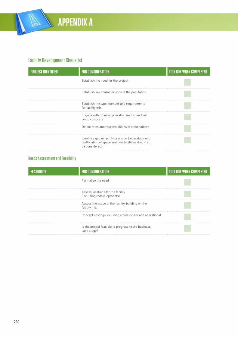
230
APPENDIX A
Facility Development Checklist
PROJECT IDENTIFIED FOR CONSIDERATION TICK BOX WHEN COMPLETED
Establish the need for the project
Establish key characteristics of the population
Establish the type, number and requirements for facility mix
Engage with other organisations/activities that could co-locate
Define roles and responsibilities of stakeholders
Identify a gap in facility provision (redevelopment, reallocation of space and new facilities should all be considered)
Needs Assessment and Feasibility
FEASIBILITY FOR CONSIDERATION TICK BOX WHEN COMPLETED
Formalise the need
Assess locations for the facility (including redevelopments)
Assess the scope of the facility, building on the facility mix
Concept costings including whole-of-life and operational
Is the project feasible to progress to the business case stage?
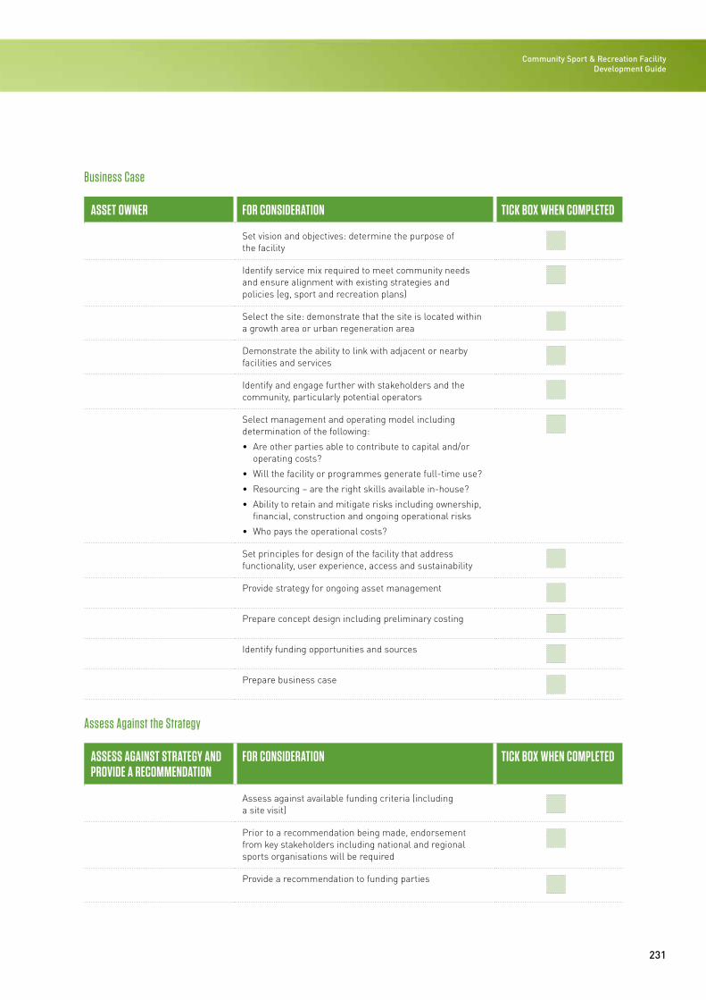
231
Community Sport & Recreation Facility Development Guide
Business Case
ASSET OWNER FOR CONSIDERATION TICK BOX WHEN COMPLETED
Set vision and objectives: determine the purpose of the facility
Identify service mix required to meet community needs and ensure alignment with existing strategies and policies (eg, sport and recreation plans)
Select the site: demonstrate that the site is located within a growth area or urban regeneration area
Demonstrate the ability to link with adjacent or nearby facilities and services
Identify and engage further with stakeholders and the community, particularly potential operators
Select management and operating model including determination of the following:
• Are other parties able to contribute to capital and/or operating costs?
• Will the facility or programmes generate full-time use?
• Resourcing – are the right skills available in-house?
• Ability to retain and mitigate risks including ownership, financial, construction and ongoing operational risks
• Who pays the operational costs?
Set principles for design of the facility that address functionality, user experience, access and sustainability
Provide strategy for ongoing asset management
Prepare concept design including preliminary costing
Identify funding opportunities and sources
Prepare business case
Assess Against the Strategy
ASSESS AGAINST STRATEGY AND PROVIDE A RECOMMENDATION
FOR CONSIDERATION TICK BOX WHEN COMPLETED
Assess against available funding criteria (including a site visit)
Prior to a recommendation being made, endorsement from key stakeholders including national and regional sports organisations will be required
Provide a recommendation to funding parties
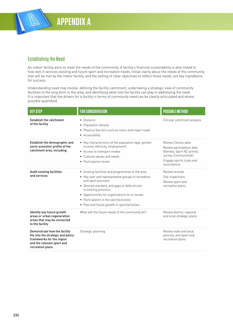
232
APPENDIX A
Establishing the NeedAn indoor facility aims to meet the needs of the community. A facility’s financial sustainability is also linked to how well it services existing and future sport and recreation needs. Initial clarity about the needs of the community that will be met by the indoor facility, and the setting of clear objectives to reflect those needs, are key ingredients for success.
Understanding need may involve: defining the facility catchment, undertaking a strategic view of community facilities in the long term in the area, and identifying what role the facility can play in addressing the need. It is important that the drivers for a facility in terms of community need can be clearly articulated and where possible quantified.
KEY STEP FOR CONSIDERATION POSSIBLE METHOD
Establish the catchment of the facility
• Distance
• Population density
• Physical barriers such as rivers and major roads
• Accessibility
Circular catchment analysis
Establish the demographic and socio-economic profile of the catchment area, including:
• Key characteristics of the population (age, gender, income, ethnicity, employment)
• Access to transport modes
• Cultural values and needs
• Participation levels
Review Census data
Review participation data (Gemba, Sport NZ activity survey, Communitrak)
Engage sports clubs and associations
Audit existing facilities and services
• Existing facilities and programmes in the area
• Key user and representative groups in recreation and sport provision
• Desired standard, and gaps or deficiencies in existing provision
• Opportunities for organisations to co-locate
• Participation in the sport/activities
• Past and future growth in sport/activities
Review records
Site inspections
Review sport and recreation plans
Identify any future growth areas or urban regeneration areas that may be connected to the facility
What will the future needs of the community be? Review district, regional and local strategic plans
Demonstrate how the facility fits into the strategic and policy frameworks for the region and the relevant sport and recreation plans
Strategic planning Review state and local policies, and sport and recreation plans
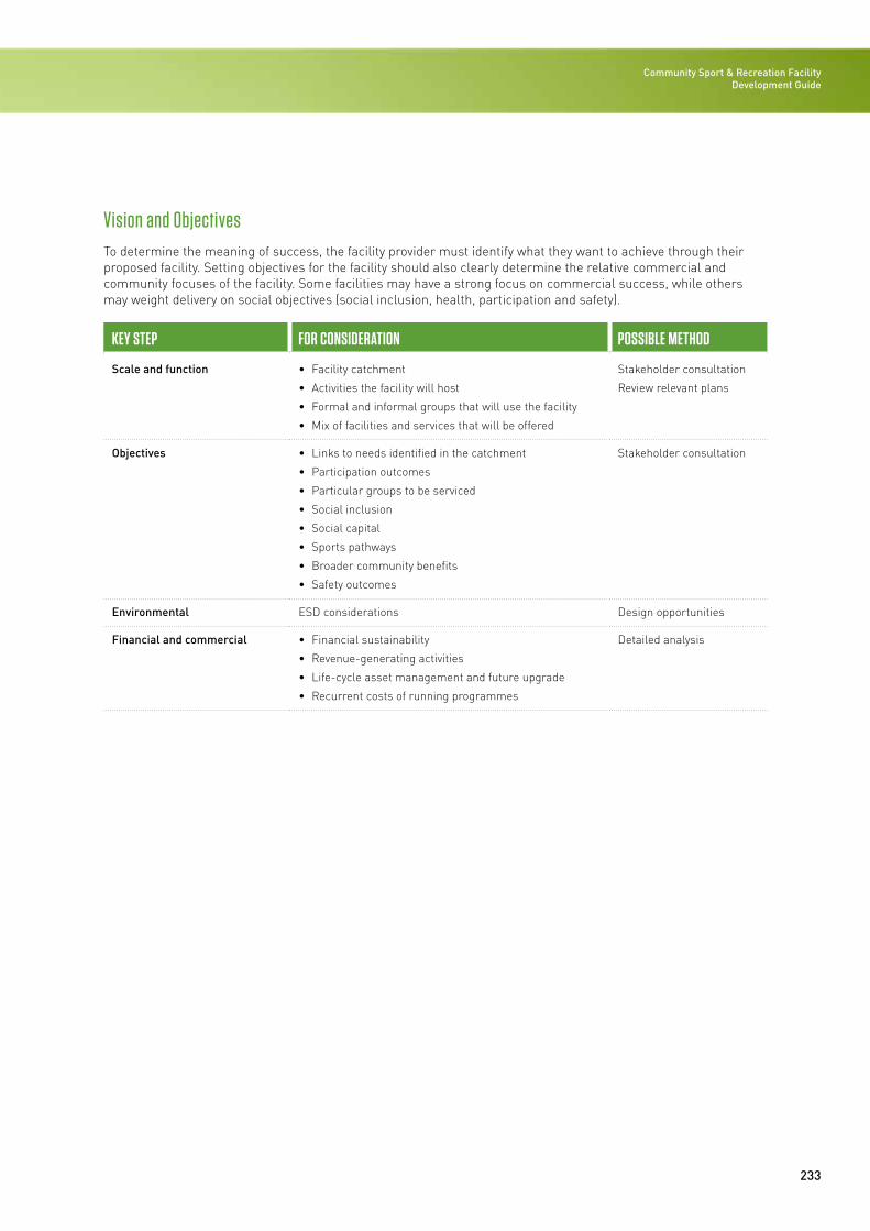
233
Community Sport & Recreation Facility Development Guide
Vision and ObjectivesTo determine the meaning of success, the facility provider must identify what they want to achieve through their proposed facility. Setting objectives for the facility should also clearly determine the relative commercial and community focuses of the facility. Some facilities may have a strong focus on commercial success, while others may weight delivery on social objectives (social inclusion, health, participation and safety).
KEY STEP FOR CONSIDERATION POSSIBLE METHOD
Scale and function • Facility catchment
• Activities the facility will host
• Formal and informal groups that will use the facility
• Mix of facilities and services that will be offered
Stakeholder consultation
Review relevant plans
Objectives • Links to needs identified in the catchment
• Participation outcomes
• Particular groups to be serviced
• Social inclusion
• Social capital
• Sports pathways
• Broader community benefits
• Safety outcomes
Stakeholder consultation
Environmental ESD considerations Design opportunities
Financial and commercial • Financial sustainability
• Revenue-generating activities
• Life-cycle asset management and future upgrade
• Recurrent costs of running programmes
Detailed analysis
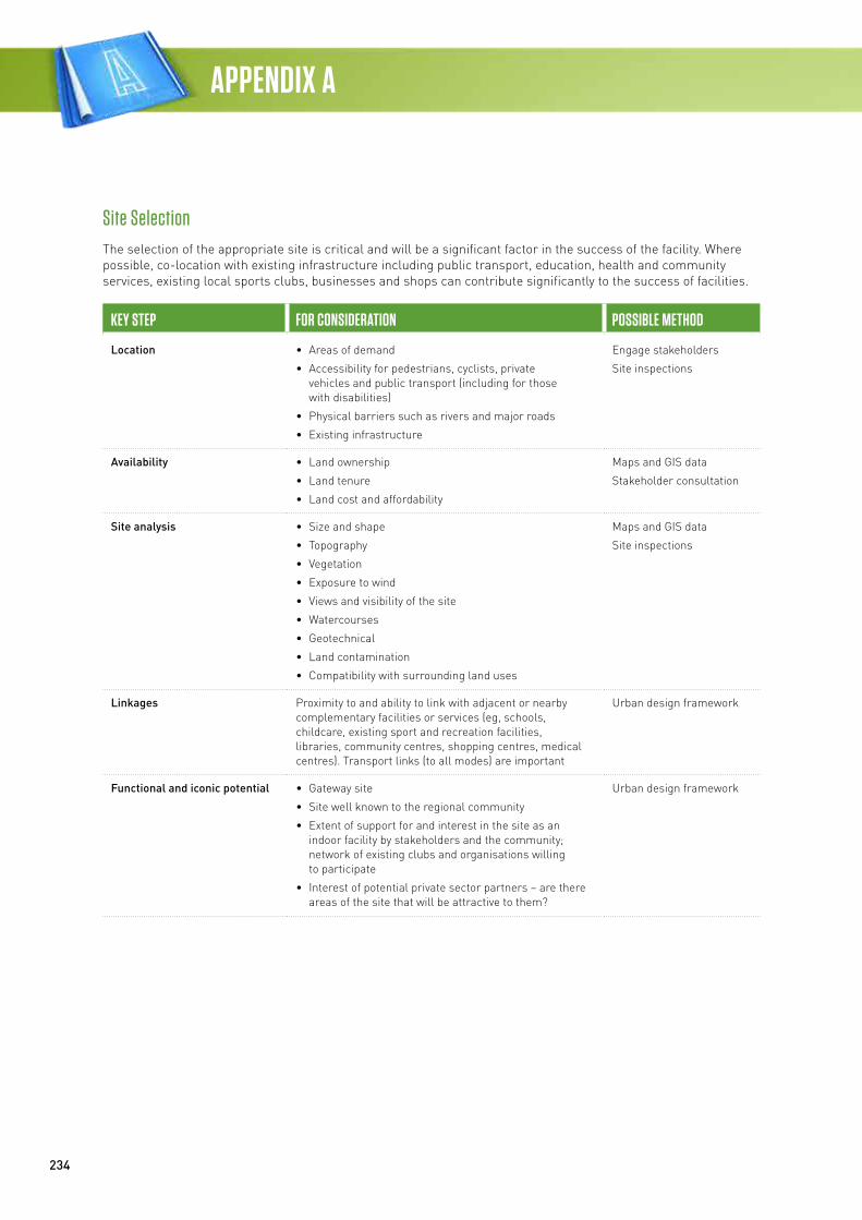
234
APPENDIX A
Site SelectionThe selection of the appropriate site is critical and will be a significant factor in the success of the facility. Where possible, co-location with existing infrastructure including public transport, education, health and community services, existing local sports clubs, businesses and shops can contribute significantly to the success of facilities.
KEY STEP FOR CONSIDERATION POSSIBLE METHOD
Location • Areas of demand
• Accessibility for pedestrians, cyclists, private vehicles and public transport (including for those with disabilities)
• Physical barriers such as rivers and major roads
• Existing infrastructure
Engage stakeholders
Site inspections
Availability • Land ownership
• Land tenure
• Land cost and affordability
Maps and GIS data
Stakeholder consultation
Site analysis • Size and shape
• Topography
• Vegetation
• Exposure to wind
• Views and visibility of the site
• Watercourses
• Geotechnical
• Land contamination
• Compatibility with surrounding land uses
Maps and GIS data
Site inspections
Linkages Proximity to and ability to link with adjacent or nearby complementary facilities or services (eg, schools, childcare, existing sport and recreation facilities, libraries, community centres, shopping centres, medical centres). Transport links (to all modes) are important
Urban design framework
Functional and iconic potential • Gateway site
• Site well known to the regional community
• Extent of support for and interest in the site as an indoor facility by stakeholders and the community; network of existing clubs and organisations willing to participate
• Interest of potential private sector partners – are there areas of the site that will be attractive to them?
Urban design framework
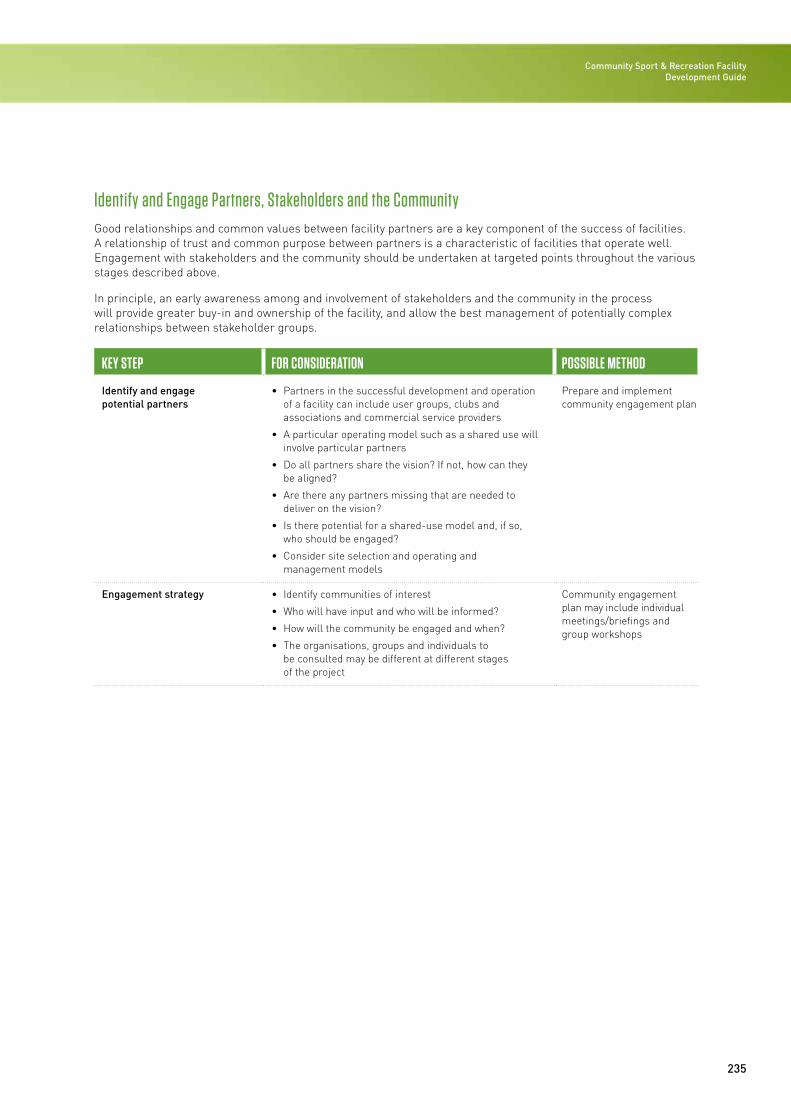
235
Community Sport & Recreation Facility Development Guide
Identify and Engage Partners, Stakeholders and the CommunityGood relationships and common values between facility partners are a key component of the success of facilities. A relationship of trust and common purpose between partners is a characteristic of facilities that operate well. Engagement with stakeholders and the community should be undertaken at targeted points throughout the various stages described above.
In principle, an early awareness among and involvement of stakeholders and the community in the process will provide greater buy-in and ownership of the facility, and allow the best management of potentially complex relationships between stakeholder groups.
KEY STEP FOR CONSIDERATION POSSIBLE METHOD
Identify and engage potential partners
• Partners in the successful development and operation of a facility can include user groups, clubs and associations and commercial service providers
• A particular operating model such as a shared use will involve particular partners
• Do all partners share the vision? If not, how can they be aligned?
• Are there any partners missing that are needed to deliver on the vision?
• Is there potential for a shared-use model and, if so, who should be engaged?
• Consider site selection and operating and management models
Prepare and implement community engagement plan
Engagement strategy • Identify communities of interest
• Who will have input and who will be informed?
• How will the community be engaged and when?
• The organisations, groups and individuals to be consulted may be different at different stages of the project
Community engagement plan may include individual meetings/briefings and group workshops
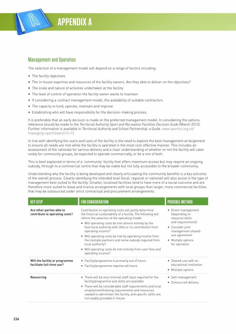
236
APPENDIX A
Management and OperationThe selection of a management model will depend on a range of factors including:
• The facility objectives
• The in-house expertise and resources of the facility owners. Are they able to deliver on the objectives?
• The scale and nature of activities undertaken at the facility
• The level of control of operation the facility owner wants to maintain
• If considering a contract management model, the availability of suitable contractors
• The capacity to fund, operate, maintain and improve
• Establishing who will have responsibility for the decision-making process.
It is preferable that an early decision is made on the preferred management model. In considering the options, reference should be made to the Territorial Authority Sport and Recreation Facilities Decision Guide (March 2013). Further information is available in Territorial Authority and School Partnership: a Guide. www.sportnz.org.nz/managing-sport/search?c=13
In line with identifying the users and uses of the facility is the need to explore the best management arrangement to ensure all needs are met while the facility is operated in the most cost-effective manner. This includes an assessment of the rationale for service delivery and a clear understanding of whether or not the facility will cater solely for community groups, be expected to operate commercially, or be a mix of both.
This is best explained in terms of a ‘community’ facility that offers maximum access but may require an ongoing subsidy, through to a commercial centre that may be viable but not fully accessible to the broader community.
Understanding why the facility is being developed and clearly articulating the community benefits is a key outcome of the overall process. Clearly identifying the intended level (local, regional or national) will also assist in the type of management best suited to the facility. Smaller, localised facilities tend to have more of a social outcome and are therefore more suited to lease and licence arrangements with local groups than larger, more commercial facilities that may be outsourced under strict contractual and procurement arrangements.
KEY STEP FOR CONSIDERATION POSSIBLE METHOD
Are other parties able to contribute to operating costs?
Contribution to operating costs will partly determine the financial sustainability of a facility. The following will inform the selection of the operating model:
• Will operating costs be met almost entirely by the host local authority with little or no contribution from operating income?
• Will operating costs be met by operating income from the multiple partners and some subsidy required from local authority?
• Will operating costs be met entirely from user fees and operating income?
• Direct management (depending on resource skills and requirements)
• Consider joint management shared-use agreement
• Multiple options for operation
Will the facility or programme facilitate full-time use?
• Facility/programme is primarily out of hours
• Facility/programme requires all hours
• Shared-use with an educational institution
• Multiple options
Resourcing • There will be very minimal staff input required for the facility/programme and skills are available
• There will be considerable staff requirements and local employment/training requirements and resources needed to administer the facility, and specific skills are not readily provided in-house
• Self-management
• Outsourced delivery
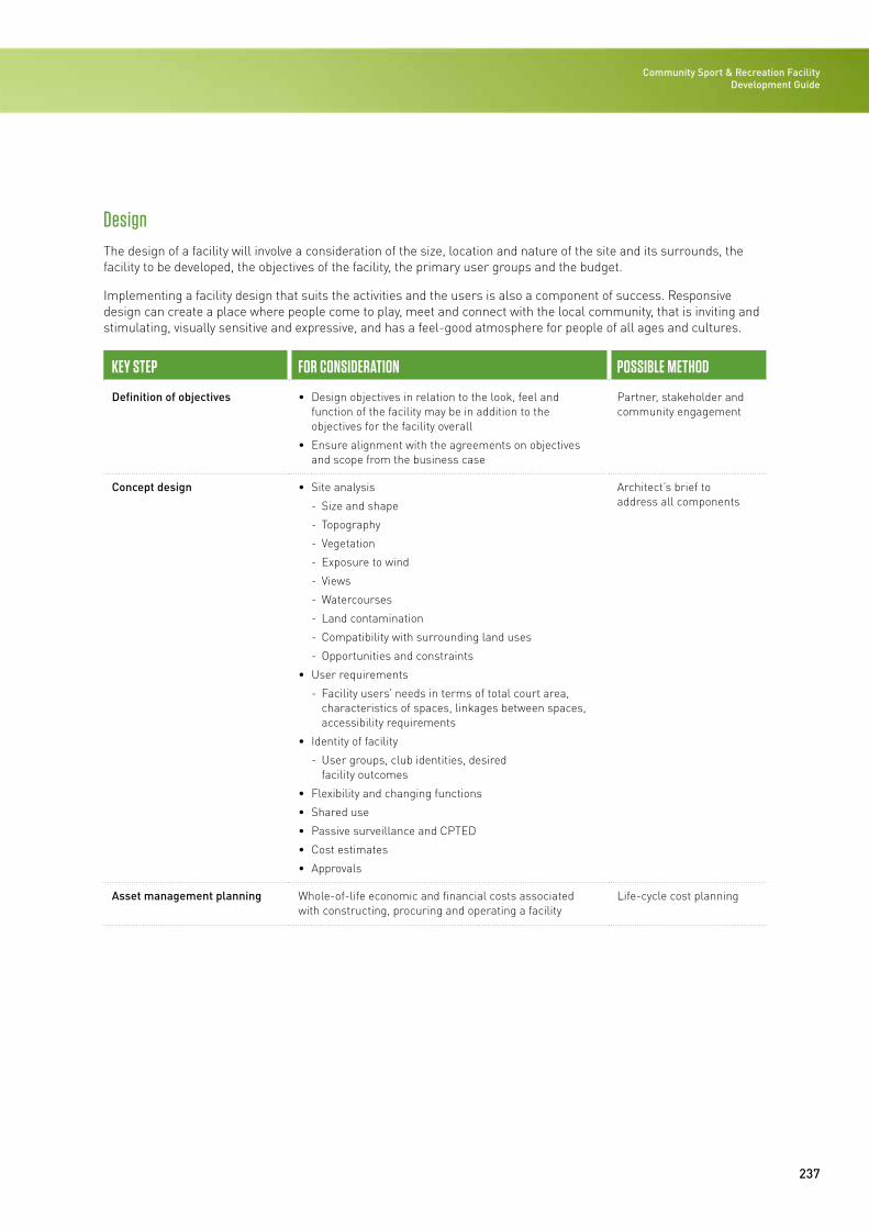
237
Community Sport & Recreation Facility Development Guide
DesignThe design of a facility will involve a consideration of the size, location and nature of the site and its surrounds, the facility to be developed, the objectives of the facility, the primary user groups and the budget.
Implementing a facility design that suits the activities and the users is also a component of success. Responsive design can create a place where people come to play, meet and connect with the local community, that is inviting and stimulating, visually sensitive and expressive, and has a feel-good atmosphere for people of all ages and cultures.
KEY STEP FOR CONSIDERATION POSSIBLE METHOD
Definition of objectives • Design objectives in relation to the look, feel and function of the facility may be in addition to the objectives for the facility overall
• Ensure alignment with the agreements on objectives and scope from the business case
Partner, stakeholder and community engagement
Concept design • Site analysis
- Size and shape
- Topography
- Vegetation
- Exposure to wind
- Views
- Watercourses
- Land contamination
- Compatibility with surrounding land uses
- Opportunities and constraints
• User requirements
- Facility users’ needs in terms of total court area, characteristics of spaces, linkages between spaces, accessibility requirements
• Identity of facility
- User groups, club identities, desired facility outcomes
• Flexibility and changing functions
• Shared use
• Passive surveillance and CPTED
• Cost estimates
• Approvals
Architect’s brief to address all components
Asset management planning Whole-of-life economic and financial costs associated with constructing, procuring and operating a facility
Life-cycle cost planning

Community Sport & Recreation Facility Development Guide / 2016
APPENDIX BAlternative strategies for affordable facilities
239
Community Sport & Recreation Facility Development GuideAPPENDIX B
Strategising the Delivery of Affordable FacilitiesWhen the project budget is under pressure, a number of critical questions need to be explored:
• Facility Size/Staging – should the facility be made smaller, or can parts of the development be staged?
• Materiality/Level of Finish – are there cheaper alternatives to the chosen materials/systems, and can the quality of finish be reduced without sacrificing long-term durability?
Facility Size/Staging
Facility size and the mix of offerings should be developed early as part of the feasibility study covered earlier in this guide.
At feasibility and early concept stage, the importance of getting good cost advice cannot be overstated. It is important that early cost indications allow a sufficient design development contingency to guide the early decision-making.
An important component of the early feasibility study is the development of a long-term development plan, or master plan.
The purpose of a long-term development plan is to investigate at an early stage of the project the various options that may be available on the site, irrespective of current budget restrictions. The aim is to investigate future development opportunities in order that sensible provision can be made within the initial development. In this way, future development opportunities are not compromised by the placement of buildings or service provision within the initial development.
Once built and operating, there is often little appetite for closing facilities to allow upgrades or extension work to occur.
Considerations when undertaking long-term development planning:
• Future facility mix – are the proposed future development objectives supported by demographic data and demand?
• Facility entry, security and control – does the entrance position allow later extension, and is it optimally located for future security and control?
• Change room location and size – can change room demand for future development be accommodated?
• Plant room location – is the plant room positioned to allow servicing and possible later enlargement?
• Parking – what is the future parking demand, and can it be accommodated?
Materiality/Level of Finish
If the budget allows, ‘doing it once and doing it right’ with the use of robust, proven materials and details is likely to lead to lower long-term operating expenditure.
One strategy in these instances may be to provide a bigger building that has ‘good bones’. The building may then achieve the brief and budget in terms of aquatic and/or dry sports provision, and allow the later upgrade of finish as funding becomes available in the longer-term.
The temptation when budget is under pressure may be to use materials and systems that appear cheap, but which have an unproven in-use history. Ultimately sports facilities rely on patronage. Attractive and legible facilities encourage return patronage, and there is therefore a limit to which the level of finish can be compromised before the quality of the facility experience is affected.
Examples of building components that might be excluded in the original development and upgraded later are as follows.
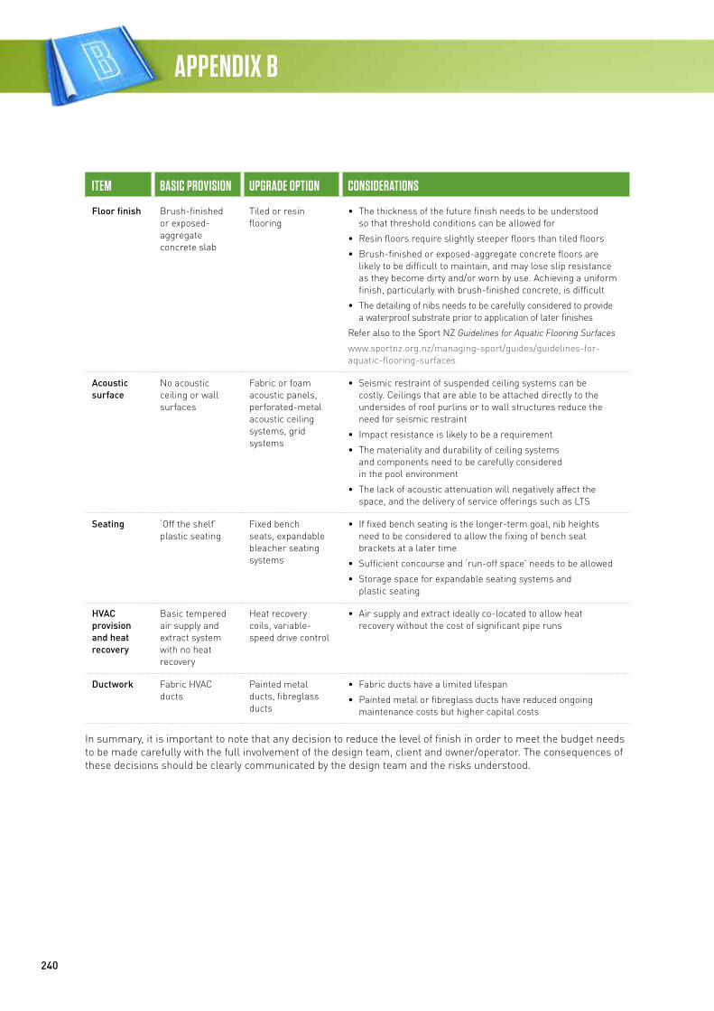
240
APPENDIX B
ITEM BASIC PROVISION UPGRADE OPTION CONSIDERATIONS
Floor finish Brush-finished or exposed-aggregate concrete slab
Tiled or resin flooring
• The thickness of the future finish needs to be understood so that threshold conditions can be allowed for
• Resin floors require slightly steeper floors than tiled floors
• Brush-finished or exposed-aggregate concrete floors are likely to be difficult to maintain, and may lose slip resistance as they become dirty and/or worn by use. Achieving a uniform finish, particularly with brush-finished concrete, is difficult
• The detailing of nibs needs to be carefully considered to provide a waterproof substrate prior to application of later finishes
Refer also to the Sport NZ Guidelines for Aquatic Flooring Surfaces
www.sportnz.org.nz/managing-sport/guides/guidelines-for-aquatic-flooring-surfaces
Acoustic surface
No acoustic ceiling or wall surfaces
Fabric or foam acoustic panels, perforated-metal acoustic ceiling systems, grid systems
• Seismic restraint of suspended ceiling systems can be costly. Ceilings that are able to be attached directly to the undersides of roof purlins or to wall structures reduce the need for seismic restraint
• Impact resistance is likely to be a requirement
• The materiality and durability of ceiling systems and components need to be carefully considered in the pool environment
• The lack of acoustic attenuation will negatively affect the space, and the delivery of service offerings such as LTS
Seating ‘Off the shelf’ plastic seating
Fixed bench seats, expandable bleacher seating systems
• If fixed bench seating is the longer-term goal, nib heights need to be considered to allow the fixing of bench seat brackets at a later time
• Sufficient concourse and ‘run-off space’ needs to be allowed
• Storage space for expandable seating systems and plastic seating
HVAC provision and heat recovery
Basic tempered air supply and extract system with no heat recovery
Heat recovery coils, variable-speed drive control
• Air supply and extract ideally co-located to allow heat recovery without the cost of significant pipe runs
Ductwork Fabric HVAC ducts
Painted metal ducts, fibreglass ducts
• Fabric ducts have a limited lifespan
• Painted metal or fibreglass ducts have reduced ongoing maintenance costs but higher capital costs
In summary, it is important to note that any decision to reduce the level of finish in order to meet the budget needs to be made carefully with the full involvement of the design team, client and owner/operator. The consequences of these decisions should be clearly communicated by the design team and the risks understood.
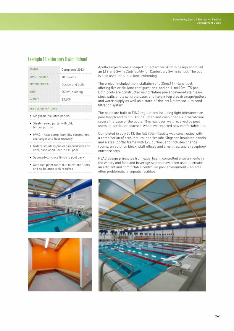
241
Community Sport & Recreation Facility Development Guide
STATUS: Completed 2013
CONSTRUCTION: 10 months
PROCUREMENT: Design and build
SIZE: 950m2, building
m2 RATE: $3,200
KEY DESIGN FEATURES
• Kingspan insulated panels
• Steel-framed portal with LVL timber purlins
• HVAC – heat pump, humidity control, heat exchanger and heat recovery
• Natare stainless pre-engineered wall and liner, cushioned liner in LTS pool
• Sponged-concrete finish to pool deck
• Compact plant room due to Natare filters and no balance tank required
Apollo Projects was engaged in September 2012 to design and build an LTS and Swim Club facility for Canterbury Swim School. The pool is also used for public lane swimming.
The project included the installation of a 25mx11m-lane pool, offering five or six-lane configurations, and an 11mx10m LTS pool. Both pools are constructed using Natare pre-engineered stainless-steel walls and a concrete base, and have integrated drainage/gutters and water supply as well as a state-of-the-art Natare vacuum sand filtration system.
The pools are built to FINA regulations including tight tolerances on pool length and depth. An insulated and cushioned PVC membrane covers the base of the pools. This has been well received by pool users, in particular coaches, who have reported how comfortable it is.
Completed in July 2013, the full 950m2 facility was constructed with a combination of architectural and firesafe Kingspan insulated panels and a steel portal frame with LVL purlins, and includes change rooms, an ablution block, staff offices and amenities, and a reception/entrance area.
HVAC design principles from expertise in controlled environments in the winery and food and beverage sectors have been used to create an efficient and comfortable controlled pool environment – an area often problematic in aquatic facilities.
Example 1 Canterbury Swim School
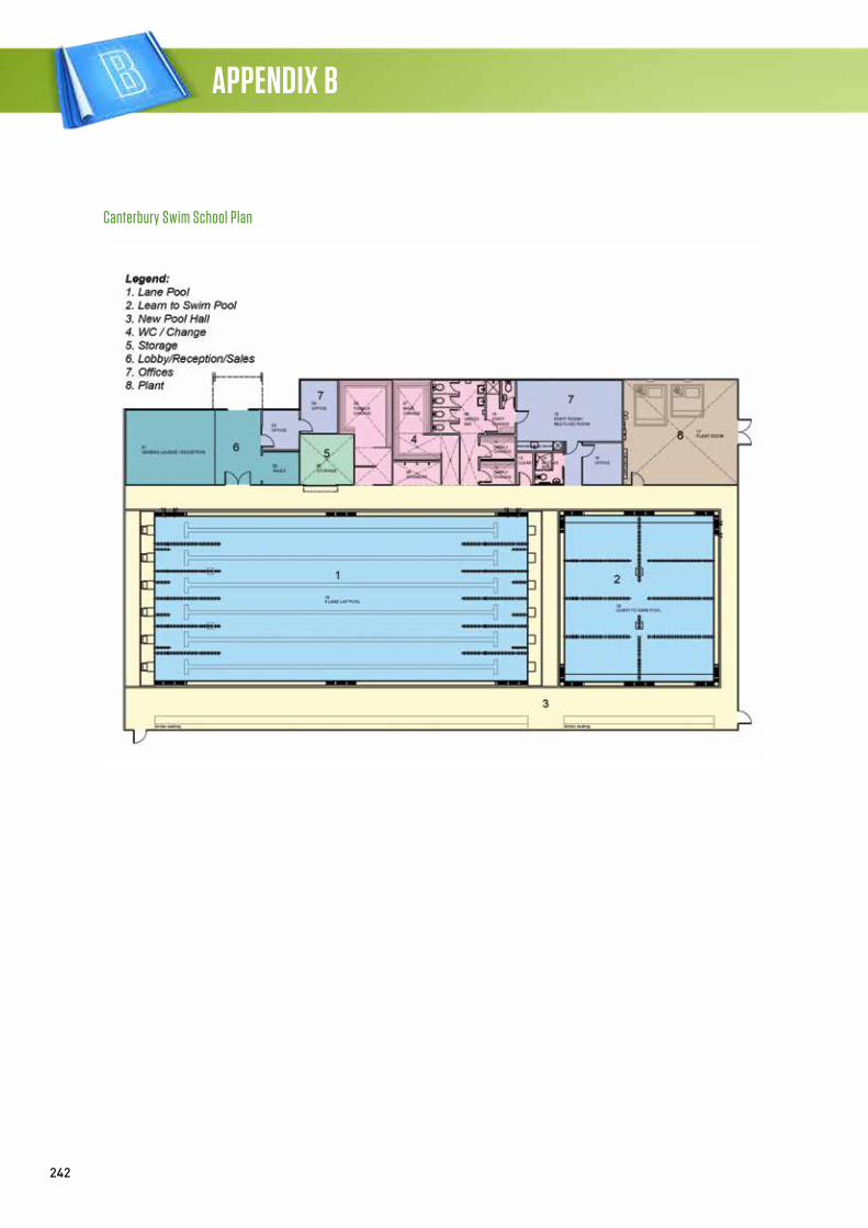
242
APPENDIX B
Canterbury Swim School Plan
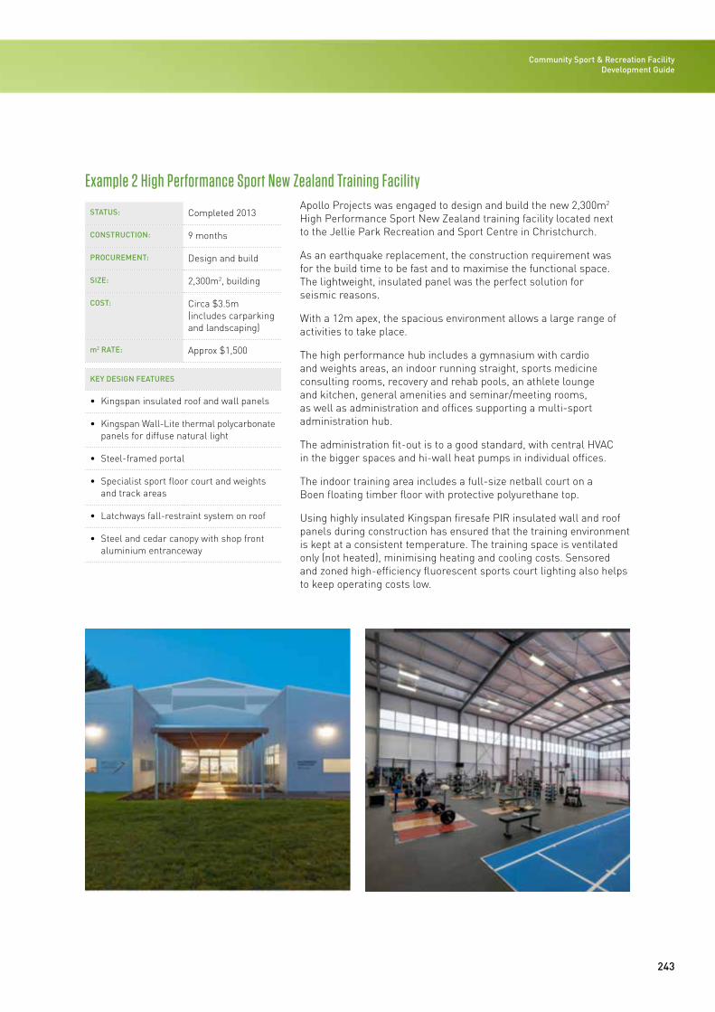
243
Community Sport & Recreation Facility Development Guide
STATUS: Completed 2013
CONSTRUCTION: 9 months
PROCUREMENT: Design and build
SIZE: 2,300m2, building
COST: Circa $3.5m (includes carparking and landscaping)
m2 RATE: Approx $1,500
KEY DESIGN FEATURES
• Kingspan insulated roof and wall panels
• Kingspan Wall-Lite thermal polycarbonate panels for diffuse natural light
• Steel-framed portal
• Specialist sport floor court and weights and track areas
• Latchways fall-restraint system on roof
• Steel and cedar canopy with shop front aluminium entranceway
Apollo Projects was engaged to design and build the new 2,300m2 High Performance Sport New Zealand training facility located next to the Jellie Park Recreation and Sport Centre in Christchurch.
As an earthquake replacement, the construction requirement was for the build time to be fast and to maximise the functional space. The lightweight, insulated panel was the perfect solution for seismic reasons.
With a 12m apex, the spacious environment allows a large range of activities to take place.
The high performance hub includes a gymnasium with cardio and weights areas, an indoor running straight, sports medicine consulting rooms, recovery and rehab pools, an athlete lounge and kitchen, general amenities and seminar/meeting rooms, as well as administration and offices supporting a multi-sport administration hub.
The administration fit-out is to a good standard, with central HVAC in the bigger spaces and hi-wall heat pumps in individual offices.
The indoor training area includes a full-size netball court on a Boen floating timber floor with protective polyurethane top.
Using highly insulated Kingspan firesafe PIR insulated wall and roof panels during construction has ensured that the training environment is kept at a consistent temperature. The training space is ventilated only (not heated), minimising heating and cooling costs. Sensored and zoned high-efficiency fluorescent sports court lighting also helps to keep operating costs low.
Example 2 High Performance Sport New Zealand Training Facility
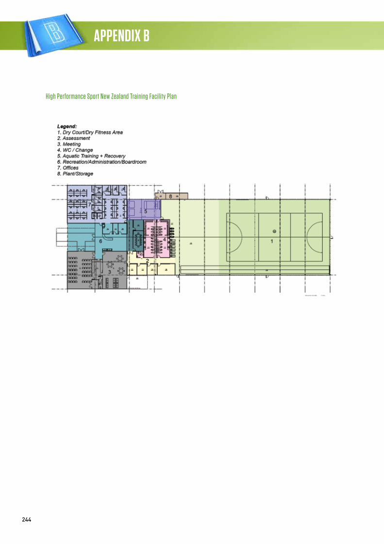
244
APPENDIX B
High Performance Sport New Zealand Training Facility Plan
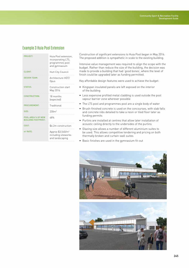
245
Community Sport & Recreation Facility Development Guide
PROJECT: Huia Pool extension, incorporating LTS, programmes pool and gymnasium
CLIENT: Hutt City Council
DESIGN TEAM: Architecture HDT/Opus
STATUS: Construction start May 2016
CONSTRUCTION: 18 months (expected)
PROCUREMENT: Traditional
SIZE: 230m2
POOL AREA % OF NEW BUILDING FOOTPRINT:
48%
COST: $6.2m construction
m2 RATE: Approx $3,540/m2 including siteworks and landscaping
Construction of significant extensions to Huia Pool began in May 2016. The proposed addition is sympathetic in scale to the existing building.
Intensive value management was required to align the scope with the budget. Rather than reduce the size of the building, the decision was made to provide a building that had ‘good bones’, where the level of finish could be upgraded later as funding permitted.
Key affordable design features were used to achieve the budget:
• Kingspan insulated panels are left exposed on the interior of the building
• Less expensive profiled metal cladding is used outside the pool vapour barrier zone wherever possible
• The LTS pool and programmes pool are a single body of water
• Brush-finished concrete is used on the concourses, with slab falls and concrete nibs detailed to take a resin or tiled floor later as funding permits
• Purlins are installed at centres that allow later installation of acoustic ceiling directly to the undersides of the purlins
• Glazing size allows a number of different aluminium suites to be used. This allows competitive tendering and pricing on both thermally broken and curtain-wall suites
• Basic finishes are used in the gymnasium fit-out
Example 3 Huia Pool Extension
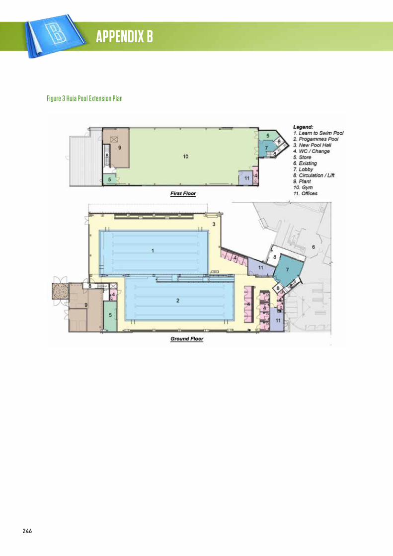
246
APPENDIX B
Figure 3 Huia Pool Extension Plan
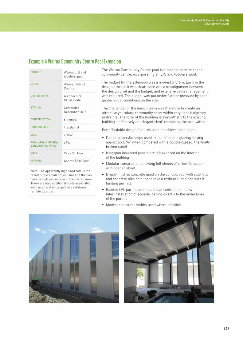
247
Community Sport & Recreation Facility Development Guide
PROJECT: Wairoa LTS and toddlers’ pool
CLIENT: Wairoa District Council
DESIGN TEAM: Architecture HDT/Create
STATUS: Completed December 2015
CONSTRUCTION: 6 months
PROCUREMENT: Traditional
SIZE: 230m2
POOL AREA % OF NEW BUILDING FOOTPRINT:
48%
COST: Circa $1.16m
m2 RATE: Approx $5,000/m2
Note. The apparently high SQM rate is the result of the small project size and the pool being a high percentage of the overall area. There are also additional costs associated with an alteration project in a relatively remote location.
The Wairoa Community Centre pool is a modest addition to the community centre, incorporating an LTS and toddlers’ pool.
The budget for the extension was a modest $1.16m. Early in the design process it was clear there was a misalignment between the design brief and the budget, and extensive value management was required. The budget was put under further pressure by poor geotechnical conditions on the site.
The challenge for the design team was therefore to create an attractive yet robust community asset within very tight budgetary restraints. The form of the building is sympathetic to the existing building – effectively an ‘elegant shed’ containing the pool within.
Key affordable design features used to achieve the budget:
• Danpalon acrylic strips used in lieu of double glazing (saving approx $500/m2 when compared with a double-glazed, thermally broken suite)
• Kingspan insulated panels are left exposed on the interior of the building
• Modular construction allowing full sheets of either Danpalon or Kingspan sheet.
• Brush-finished concrete used on the concourses, with slab falls and concrete nibs detailed to take a resin or tiled floor later if funding permits
• Painted LVL purlins are installed at centres that allow later installation of acoustic ceiling directly to the undersides of the purlins
• Modest concourse widths used where possible.
Example 4 Wairoa Community Centre Pool Extension
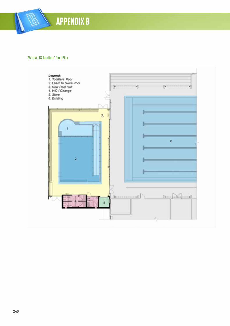
248
APPENDIX B
Wairoa LTS Toddlers’ Pool Plan
Community Sport & Recreation Facility Development Guide / 2016
APPENDIX CACRONYMS
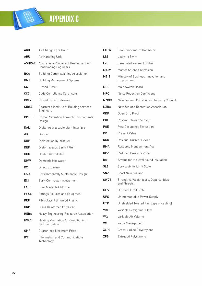
250
APPENDIX C
ACH Air Changes per Hour
AHU Air Handling Unit
ASHRAE Australasian Society of Heating and Air Conditioning Engineers
BCA Building Commissioning Association
BMS Building Management System
CC Closed Circuit
CCC Code Compliance Certificate
CCTV Closed Circuit Television
CIBSE Chartered Institute of Building services Engineers
CPTED Crime Prevention Through Environmental Design
DALI Digital Addressable Light Interface
dB Decibel
DBP Disinfection by-product
DEF Diatomaceous Earth Filter
DGU Double Glazed Unit
DHW Domestic Hot Water
DX Direct Expansion
ESD Environmentally Sustainable Design
ECI Early Contractor Involvement
FAC Free Available Chlorine
FF&E Fittings Fixtures and Equipment
FRP Fibreglass Reinforced Plastic
GRP Glass Reinforced Polyester
HERA Heavy Engineering Research Association
HVAC Heating Ventilation Air Conditioning and Circulation
GMP Guaranteed Maximum Price
ICT Information and Communications Technology
LTHW Low Temperature Hot Water
LTS Learn to Swim
LVL Laminated Veneer Lumber
MATV Master Antenna Television
MBIE Ministry of Business Innovation and Employment
MSB Main Switch Board
NRC Noise Reduction Coefficient
NZCIC New Zealand Construction Industry Council
NZRA New Zealand Recreation Association
ODP Open Drip Proof
PIR Passive Infrared Sensor
POE Post Occupancy Evaluation
PV Present Value
RCD Residual Current Device
RMA Resource Management Act
RPZ Reduced Pressure Zone
Rw A value for the level sound insulation
SLS Serviceability Limit State
SNZ Sport New Zealand
SWOT Strengths, Weaknesses, Opportunities and Threats
ULS Ultimate Limit State
UPS Uninterruptable Power Supply
UTP Unshielded Twisted Pair (type of cabling)
VRF Variable Refrigerant Flow
VAV Variable Air Volume
VM Value Management
XLPE Cross-Linked Polyethylene
XPS Extruded Polystyrene