Embed Size (px)
Citation preview

SpecificationsWing span ____________________________ 155cm.Wing area _________________________ 3950 sq cm .Approximate flying weight _______________ 2.6-2.8kg.Recommended engine size 0.40-0.46 cu. ins 2-stroke.Recommended R/C __________ 4 channels minimum.Flying skill level ___________________ Sports Trainer.Electric conversion: optional
Kit features.
• Ready-made—minimal assembly & finishing required.• Ready-covered—including decals, trim & covering.• Factory-installed pushrod.• Factory-pinned & glued control surface hinges for ultimate safety.• Comprehensive hardware pack including wheels, tank, spats,undercarriage& spinner.• Photo-illustrated step-by-step Assembly Manual.
Hand-made Almost Ready to Fly R/C Model Aircraft
ASSEMBLY MANUAL
Additional items required.Engine.4 Channels or greater Radio Control system.Glues.Tools.Starting Equipment.
Made in Vietnam.
SPORTS TRAINER - ENGINE SIZE.40 - .46 - 2STROKE
2
BOOMERANG 40. Instruction Manual.
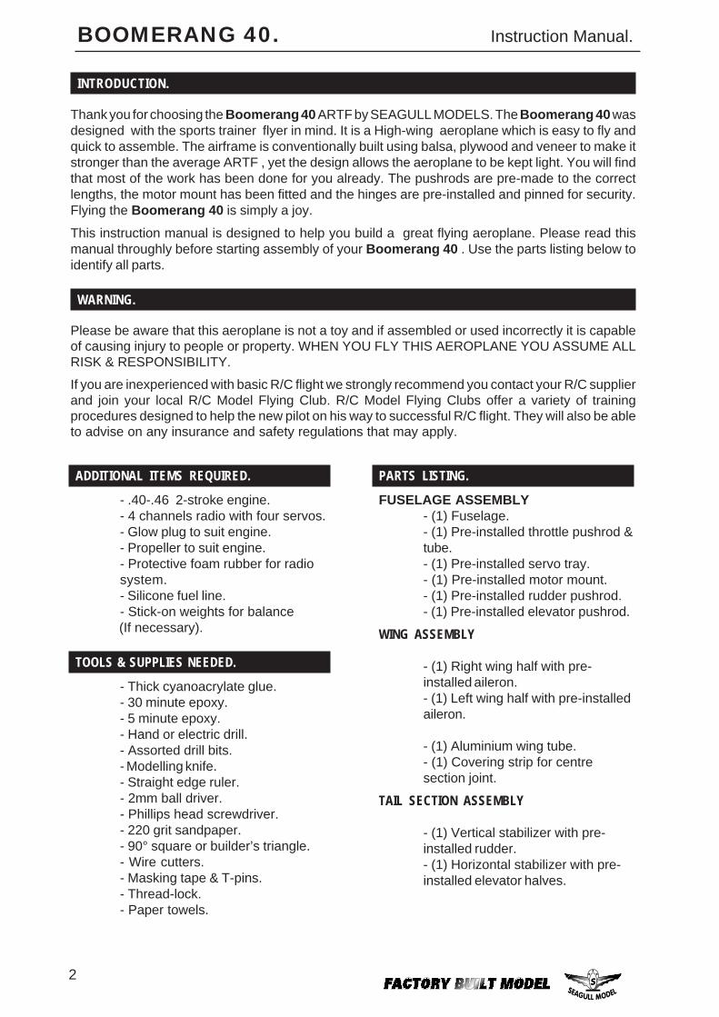
INTRODUCTION.
Thank you for choosing the Boomerang 40 ARTF by SEAGULL MODELS. The Boomerang 40 wasdesigned with the sports trainer flyer in mind. It is a High-wing aeroplane which is easy to fly andquick to assemble. The airframe is conventionally built using balsa, plywood and veneer to make itstronger than the average ARTF , yet the design allows the aeroplane to be kept light. You will findthat most of the work has been done for you already. The pushrods are pre-made to the correctlengths, the motor mount has been fitted and the hinges are pre-installed and pinned for security.Flying the Boomerang 40 is simply a joy.
This instruction manual is designed to help you build a great flying aeroplane. Please read thismanual throughly before starting assembly of your Boomerang 40 . Use the parts listing below toidentify all parts.
WARNING.
Please be aware that this aeroplane is not a toy and if assembled or used incorrectly it is capableof causing injury to people or property. WHEN YOU FLY THIS AEROPLANE YOU ASSUME ALLRISK & RESPONSIBILITY.
If you are inexperienced with basic R/C flight we strongly recommend you contact your R/C supplierand join your local R/C Model Flying Club. R/C Model Flying Clubs offer a variety of trainingprocedures designed to help the new pilot on his way to successful R/C flight. They will also be ableto advise on any insurance and safety regulations that may apply.
ADDITIONAL ITEMS REQUIRED.
- .40-.46 2-stroke engine.- 4 channels radio with four servos.- Glow plug to suit engine.- Propeller to suit engine.- Protective foam rubber for radiosystem.- Silicone fuel line.- Stick-on weights for balance
(If necessary).
TOOLS & SUPPLIES NEEDED.
- Thick cyanoacrylate glue.- 30 minute epoxy.- 5 minute epoxy.- Hand or electric drill.- Assorted drill bits.- Modelling knife.- Straight edge ruler.- 2mm ball driver.- Phillips head screwdriver.- 220 grit sandpaper.- 90° square or builder’s triangle.- Wire cutters.- Masking tape & T-pins.- Thread-lock.- Paper towels.
PARTS LISTING.
FUSELAGE ASSEMBLY- (1) Fuselage.- (1) Pre-installed throttle pushrod &tube.- (1) Pre-installed servo tray.- (1) Pre-installed motor mount.- (1) Pre-installed rudder pushrod.- (1) Pre-installed elevator pushrod.
WING ASSEMBLY
- (1) Right wing half with pre-installed aileron.- (1) Left wing half with pre-installedaileron.
- (1) Aluminium wing tube.- (1) Covering strip for centresection joint.
TAIL SECTION ASSEMBLY
- (1) Vertical stabilizer with pre-installed rudder.- (1) Horizontal stabilizer with pre-installed elevator halves.
3
BOOMERANG 40. Instruction Manual.
NOTE: To avoid scratching your new aero-plane we suggest that you coveryour workbench with an old towel.Keep a couple of jars or bowls handyto hold the small parts after you openthe bags.Please trial fit all parts. Make sureyou have the correct parts and thatthey fit and are aligned properly be-fore gluing! This will ensure properassembly as the Boomerang 40 ismade from natural materials andminor adjustments may have to bemade.The paint and plastic parts used inthis kit are fuel proof. However, theyare not tolerant of many harsh chemi-cals including the following: paintthinner, cyano-acrylate glue accel-erator, cyanoacrylate glue de-bonderand acetone. Do not let these chemi-cals come in contact with the colourson the covering and the plastic parts.
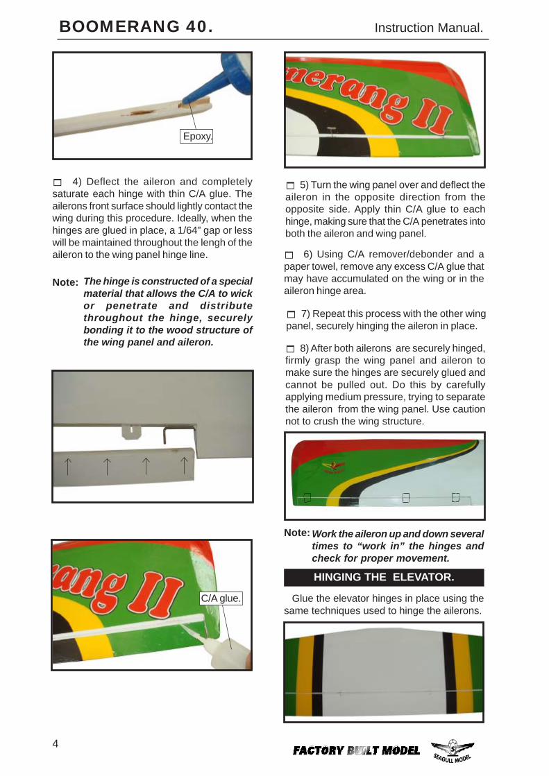
2) Remove each hinge from the wing paneland aileron and place a T-pin in the center ofeach hinge. Slide each hinge into the wingpanel until the T-pin is snug against the wingpanel. This will help ensure an equal amountof hinge is on either side of the hinge line whenthe aileron is mounted to the aileron.
The control surfaces, including theailerons, elevators, and rudder, areprehinged with hinges installed, but thehinges are not glued in place. It isimperative that you properly adhere thehinges in place per the steps that followusing a high-quality thin C/A glue.
Note:
HINGING THE AILERONS.
Hinge.
3) Slide the wing panel on the aileron untilthere is only a slight gap. The hinge is nowcentered on the wing panel and aileron.Remove the T-pins and snug the aileronagainst the wing panel. A gap of 1/64” or lessshould be maintained between the wing paneland aileron.
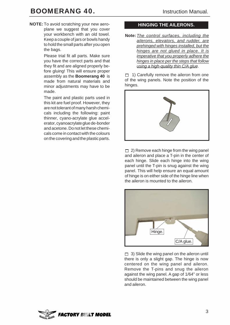
1) Carefully remove the aileron from oneof the wing panels. Note the position of thehinges.
C/A glue.
4
BOOMERANG 40. Instruction Manual.
8) After both ailerons are securely hinged,firmly grasp the wing panel and aileron tomake sure the hinges are securely glued andcannot be pulled out. Do this by carefullyapplying medium pressure, trying to separatethe aileron from the wing panel. Use cautionnot to crush the wing structure.
7) Repeat this process with the other wingpanel, securely hinging the aileron in place.
6) Using C/A remover/debonder and apaper towel, remove any excess C/A glue thatmay have accumulated on the wing or in theaileron hinge area.
5) Turn the wing panel over and deflect theaileron in the opposite direction from theopposite side. Apply thin C/A glue to eachhinge, making sure that the C/A penetrates intoboth the aileron and wing panel.
Work the aileron up and down severaltimes to “work in” the hinges andcheck for proper movement.
Note:
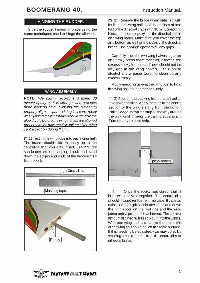
4) Deflect the aileron and completelysaturate each hinge with thin C/A glue. Theailerons front surface should lightly contact thewing during this procedure. Ideally, when thehinges are glued in place, a 1/64” gap or lesswill be maintained throughout the lengh of theaileron to the wing panel hinge line.
The hinge is constructed of a specialmaterial that allows the C/A to wickor penetrate and distributethroughout the hinge, securelybonding it to the wood structure ofthe wing panel and aileron.
Note:
Epoxy.
HINGING THE ELEVATOR.
Glue the elevator hinges in place using thesame techniques used to hinge the ailerons.
C/A glue.
5
BOOMERANG 40. Instruction Manual.
Masking tape.
Centre line.
2) Remove the brace when satisfied withits fit ineach wing half. Coat both sides of onehalf of the dihedral brace with 30 minute epoxy.Next, pour some epoxy into the dihedral box inone wing panel. Make sure you cover the topand bottom as well as the sides of the dihedralbrace. Use enough epoxy to fill any gaps.
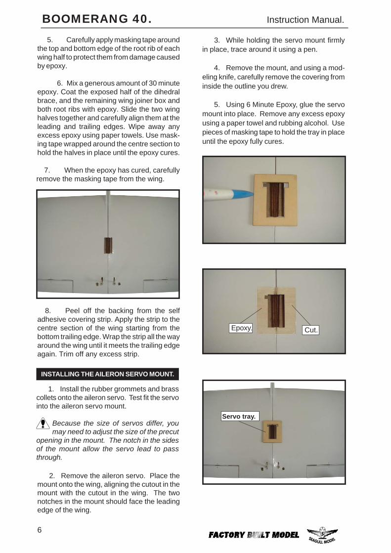
1) Test fit the wing tube into each wing half.The brace should slide in easily up to thecentreline that you drew.If not, use 220 gritsandpaper with a sanding block and sanddown the edges and ends of the brace until itfits properly.
WING ASSEMBLY.
NOTE: We highly recommend using 30minute epoxy as it is stronger and providesmore working time, allowing the builder toproperly align the parts. Using fast cure epoxywhen joining the wing halves could result in theglue drying before the wing halves are alignedproperly which may result in failure of the wingcentre section during flight.
Carefully slide the two wing halves togetherand firmly press them together, allowing theexcess epoxy to run out. There should not beany gap in the wing halves. Use rubbingalcohol and a paper tower to clean up anyexcess epoxy.
Apply masking tape at the wing join to holdthe wing halves together securely.
HINGING THE RUDDER.
Glue the rudder hinges in place using thesame techniques used to hinge the ailerons.
Epoxy attach.
3) Peel off the backing from the self adhe-sive covering strip. Apply the strip to the centresection of the wing starting from the bottomtrailing edge. Wrap the strip all the way aroundthe wing until it meets the trailing edge again.Trim off any excess strip.
4. Once the epoxy has cured, trial fitboth wing halves together. The centre ribsshould fit together flush with no gaps. If gaps doexist, use 220 grit sandpaper and sand downthe high spots on the root ribs and the wingjoiner until a proper fit is achieved. The correctamount of dihedral is ready-built into the wings.With one wing half laid flat on the table, theother wing tip should be off the table surface.If this needs to be adjusted, you may do so bysanding small amounts from the centre ribs ordihedral brace.Epoxy.
6
BOOMERANG 40. Instruction Manual.
5. Carefully apply masking tape aroundthe top and bottom edge of the root rib of eachwing half to protect them from damage causedby epoxy.
6. Mix a generous amount of 30 minuteepoxy. Coat the exposed half of the dihedralbrace, and the remaining wing joiner box andboth root ribs with epoxy. Slide the two winghalves together and carefully align them at theleading and trailing edges. Wipe away anyexcess epoxy using paper towels. Use mask-ing tape wrapped around the centre section tohold the halves in place until the epoxy cures.
2. Remove the aileron servo. Place themount onto the wing, aligning the cutout in themount with the cutout in the wing. The twonotches in the mount should face the leadingedge of the wing.
3. While holding the servo mount firmlyin place, trace around it using a pen.
4. Remove the mount, and using a mod-eling knife, carefully remove the covering frominside the outline you drew.
5. Using 6 Minute Epoxy, glue the servomount into place. Remove any excess epoxyusing a paper towel and rubbing alcohol. Usepieces of masking tape to hold the tray in placeuntil the epoxy fully cures.
INSTALLING THE AILERON SERVO MOUNT.
8. Peel off the backing from the selfadhesive covering strip. Apply the strip to thecentre section of the wing starting from thebottom trailing edge. Wrap the strip all the wayaround the wing until it meets the trailing edgeagain. Trim off any excess strip.
7. When the epoxy has cured, carefullyremove the masking tape from the wing.
1. Install the rubber grommets and brasscollets onto the aileron servo. Test fit the servointo the aileron servo mount.
Because the size of servos differ, youmay need to adjust the size of the precut
opening in the mount. The notch in the sidesof the mount allow the servo lead to passthrough.
Epoxy. Cut.
Servo tray.
7
BOOMERANG 40. Instruction Manual.
INSTALLING THE AILERON SERVO.
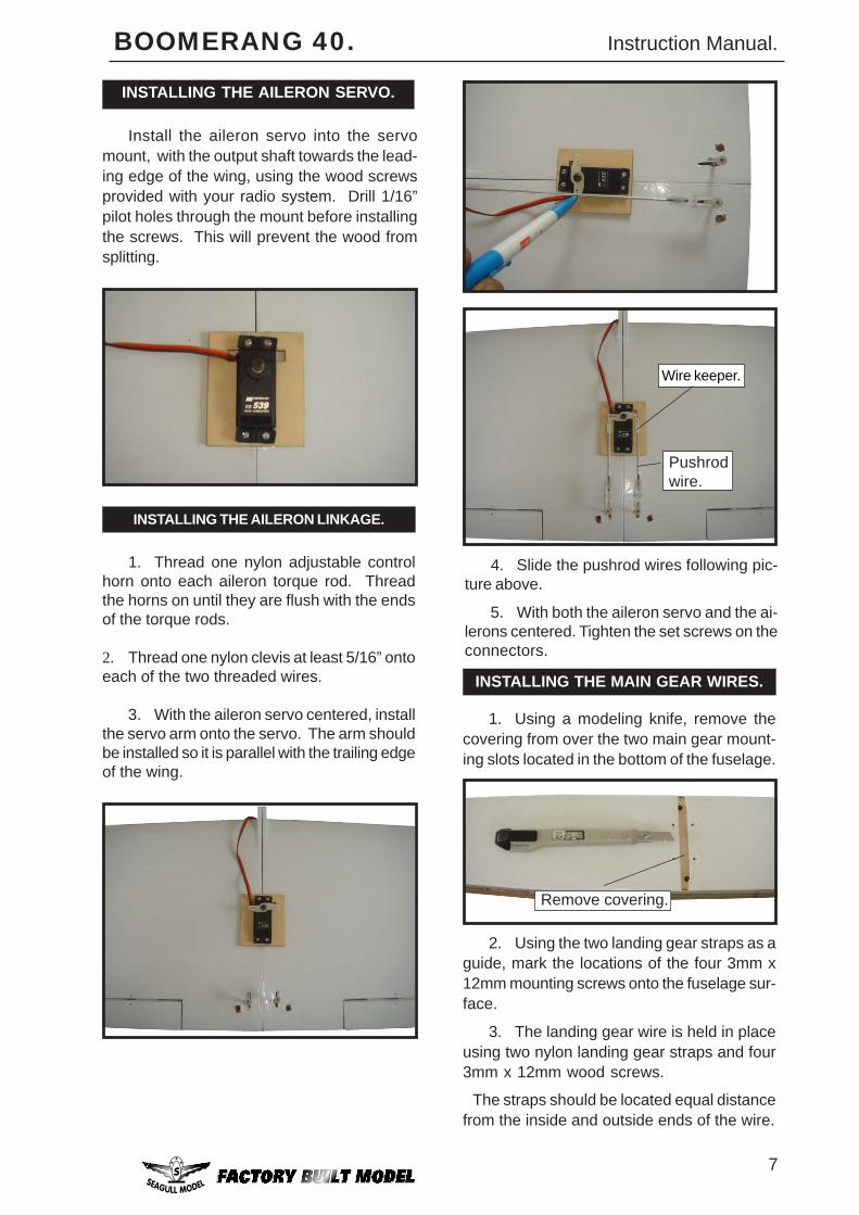
Install the aileron servo into the servomount, with the output shaft towards the lead-ing edge of the wing, using the wood screwsprovided with your radio system. Drill 1/16”pilot holes through the mount before installingthe screws. This will prevent the wood fromsplitting.
1. Thread one nylon adjustable controlhorn onto each aileron torque rod. Threadthe horns on until they are flush with the endsof the torque rods.
2. Thread one nylon clevis at least 5/16” ontoeach of the two threaded wires.
3. With the aileron servo centered, installthe servo arm onto the servo. The arm shouldbe installed so it is parallel with the trailing edgeof the wing.
Pushrodwire.
4. Slide the pushrod wires following pic-ture above.
5. With both the aileron servo and the ai-lerons centered. Tighten the set screws on theconnectors.
Wire keeper.
INSTALLING THE AILERON LINKAGE.
1. Using a modeling knife, remove thecovering from over the two main gear mount-ing slots located in the bottom of the fuselage.
2. Using the two landing gear straps as aguide, mark the locations of the four 3mm x12mm mounting screws onto the fuselage sur-face.
Remove covering.
INSTALLING THE MAIN GEAR WIRES.
3. The landing gear wire is held in placeusing two nylon landing gear straps and four3mm x 12mm wood screws.
The straps should be located equal distancefrom the inside and outside ends of the wire.
8
BOOMERANG 40. Instruction Manual.
1) Locate the items necessary to install theengine mount included with your model. .
ENGINE MOUNT INSTALLATION.
4x30mm.
2) Use four 4x30mm head bolts and four 4mmwashers to attach the engine mount rails tothe firewall. Tighten the screws . Make sure touse threadlock on the screws to help preventthem from vibrating loose.
2mm.
3mm X 12mm.
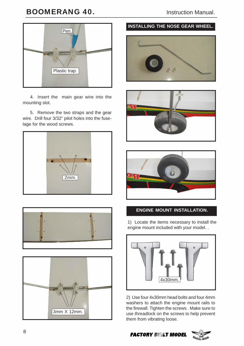
5. Remove the two straps and the gearwire. Drill four 3/32” pilot holes into the fuse-lage for the wood screws.
Plastic trap.
Pen.
4. Insert the main gear wire into themounting slot.
INSTALLING THE NOSE GEAR WHEEL.
9
BOOMERANG 40. Instruction Manual.
FUEL TANK.
INSTALLING THE STOPPER ASSEMBLY.
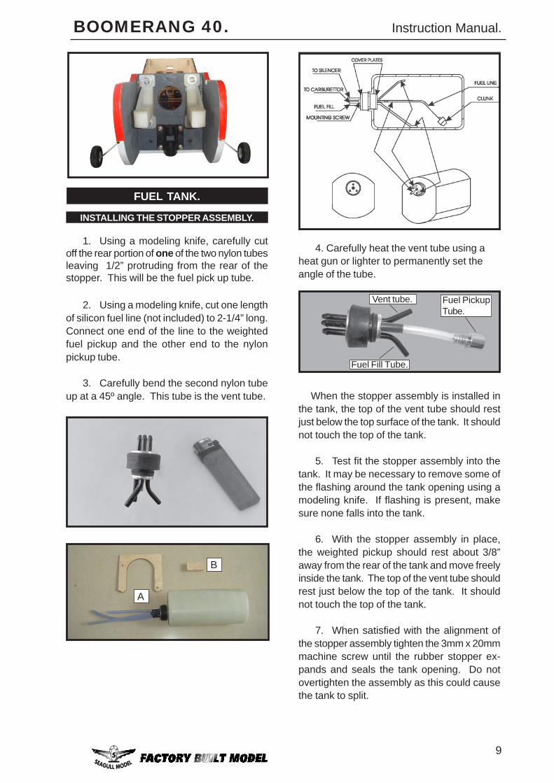
1. Using a modeling knife, carefully cutoff the rear portion of one of the two nylon tubesleaving 1/2” protruding from the rear of thestopper. This will be the fuel pick up tube.
2. Using a modeling knife, cut one lengthof silicon fuel line (not included) to 2-1/4” long.Connect one end of the line to the weightedfuel pickup and the other end to the nylonpickup tube.
3. Carefully bend the second nylon tubeup at a 45º angle. This tube is the vent tube.
4. Carefully heat the vent tube using aheat gun or lighter to permanently set theangle of the tube.
Fuel PickupTube.
Fuel Fill Tube.
Vent tube.
A
B
When the stopper assembly is installed inthe tank, the top of the vent tube should restjust below the top surface of the tank. It shouldnot touch the top of the tank.
5. Test fit the stopper assembly into thetank. It may be necessary to remove some ofthe flashing around the tank opening using amodeling knife. If flashing is present, makesure none falls into the tank.
6. With the stopper assembly in place,the weighted pickup should rest about 3/8”away from the rear of the tank and move freelyinside the tank. The top of the vent tube shouldrest just below the top of the tank. It shouldnot touch the top of the tank.
7. When satisfied with the alignment ofthe stopper assembly tighten the 3mm x 20mmmachine screw until the rubber stopper ex-pands and seals the tank opening. Do notovertighten the assembly as this could causethe tank to split.
10
BOOMERANG 40. Instruction Manual.
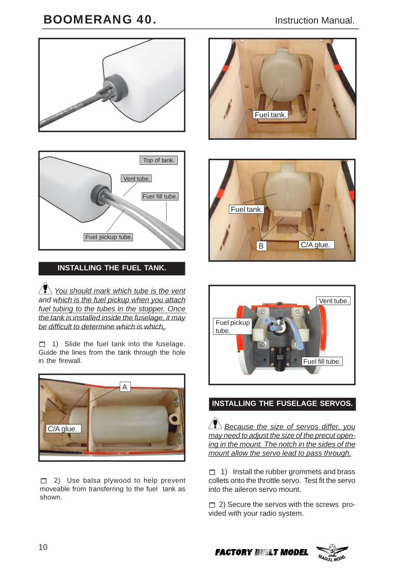
Fuel pickuptube.
Vent tube.
Fuel fill tube.
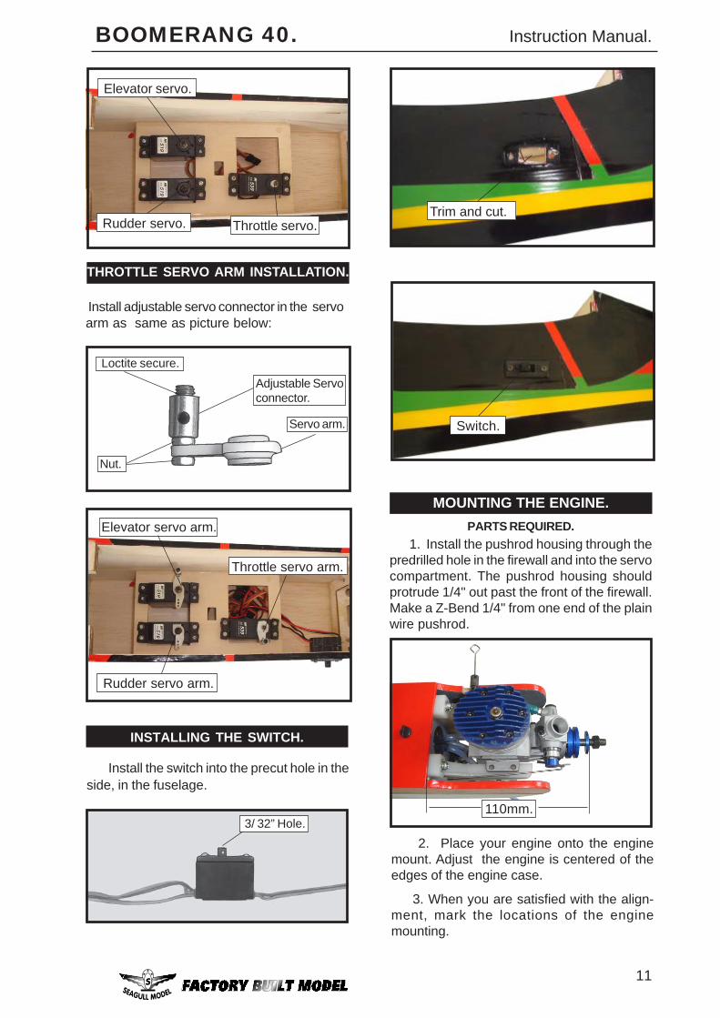
INSTALLING THE FUSELAGE SERVOS.
1) Install the rubber grommets and brasscollets onto the throttle servo. Test fit the servointo the aileron servo mount.
2) Secure the servos with the screws pro-vided with your radio system.
Because the size of servos differ, youmay need to adjust the size of the precut open-ing in the mount. The notch in the sides of themount allow the servo lead to pass through.
Fuel tank.
INSTALLING THE FUEL TANK.
Fuel tank.
C/A glue.Fuel pickup tube.
Top of tank.
Vent tube.
Fuel fill tube.
2) Use balsa plywood to help preventmoveable from transferring to the fuel tank asshown.
1) Slide the fuel tank into the fuselage.Guide the lines from the tank through the holein the firewall.
You should mark which tube is the ventand which is the fuel pickup when you attachfuel tubing to the tubes in the stopper. Oncethe tank is installed inside the fuselage, it maybe difficult to determine which is which.
A
B
C/A glue.
11
BOOMERANG 40. Instruction Manual.
Throttle servo.
Elevator servo.
Rudder servo.
THROTTLE SERVO ARM INSTALLATION.
Install adjustable servo connector in the servoarm as same as picture below:
Adjustable Servoconnector.
Servo arm.
Loctite secure.
Nut.
Elevator servo arm.
Throttle servo arm.
Rudder servo arm.
INSTALLING THE SWITCH.
3/ 32” Hole.
Trim and cut.
Install the switch into the precut hole in theside, in the fuselage.
Switch.
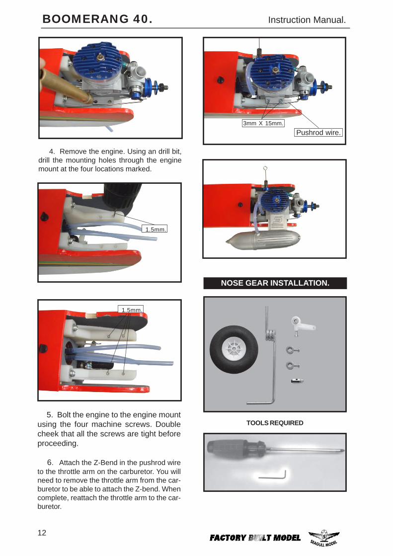
MOUNTING THE ENGINE.PARTS REQUIRED.
1. Install the pushrod housing through thepredrilled hole in the firewall and into the servocompartment. The pushrod housing shouldprotrude 1/4" out past the front of the firewall.Make a Z-Bend 1/4" from one end of the plainwire pushrod.
110mm.
2. Place your engine onto the enginemount. Adjust the engine is centered of theedges of the engine case.
3. When you are satisfied with the align-ment, mark the locations of the enginemounting.
12
BOOMERANG 40. Instruction Manual.
NOSE GEAR INSTALLATION.
TOOLS REQUIRED
3mm X 15mm.
1.5mm.
5. Bolt the engine to the engine mountusing the four machine screws. Doublecheek that all the screws are tight beforeproceeding.
6. Attach the Z-Bend in the pushrod wireto the throttle arm on the carburetor. You willneed to remove the throttle arm from the car-buretor to be able to attach the Z-bend. Whencomplete, reattach the throttle arm to the car-buretor.
Pushrod wire.
1.5mm.
4. Remove the engine. Using an drill bit,drill the mounting holes through the enginemount at the four locations marked.
13
BOOMERANG 40. Instruction Manual.
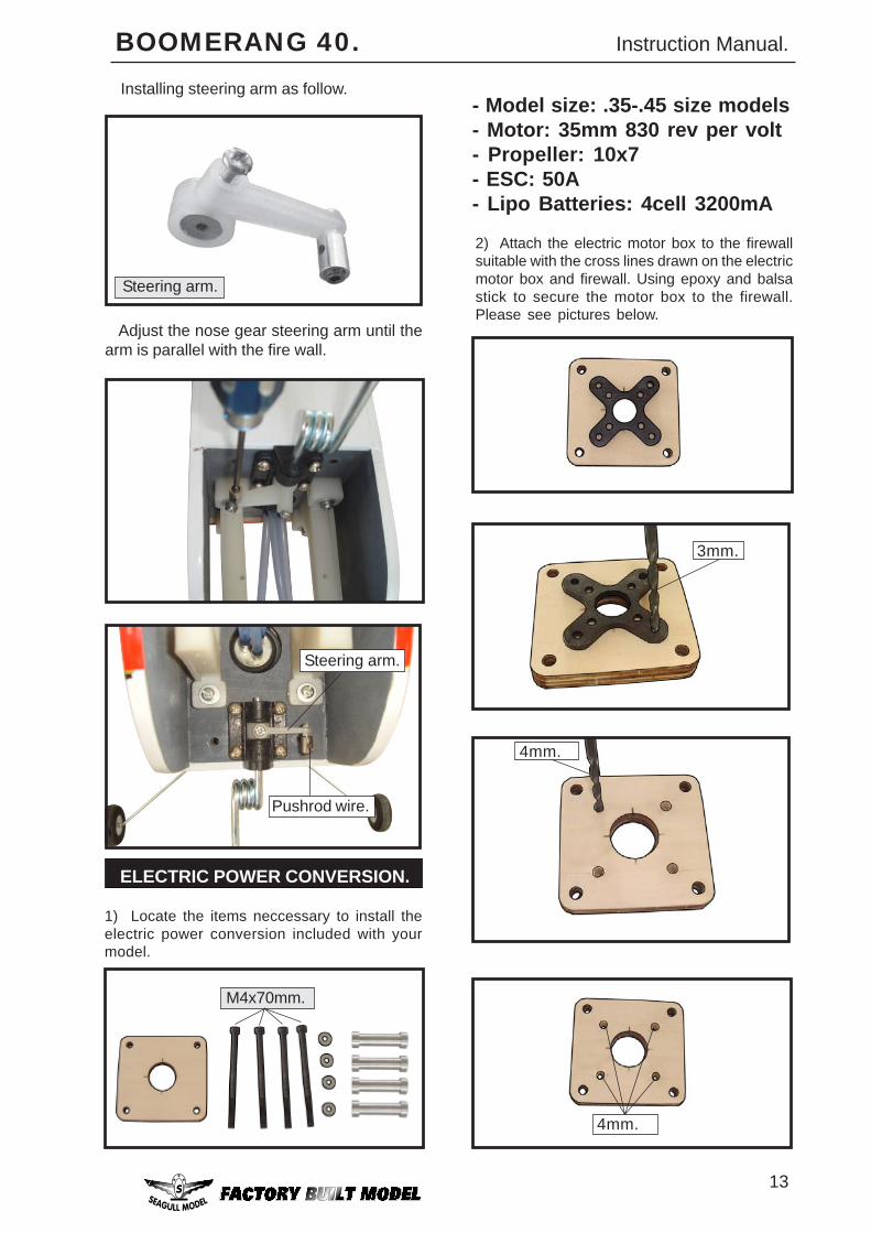
Steering arm.
Installing steering arm as follow.
Adjust the nose gear steering arm until thearm is parallel with the fire wall.
Steering arm.
Pushrod wire.
ELECTRIC POWER CONVERSION.
1) Locate the items neccessary to install theelectric power conversion included with yourmodel.
- Model size: .35-.45 size models- Motor: 35mm 830 rev per volt- Propeller: 10x7- ESC: 50A- Lipo Batteries: 4cell 3200mA
M4x70mm.
2) Attach the electric motor box to the firewallsuitable with the cross lines drawn on the electricmotor box and firewall. Using epoxy and balsastick to secure the motor box to the firewall.Please see pictures below.
3mm.
4mm.
4mm.
14
BOOMERANG 40. Instruction Manual.
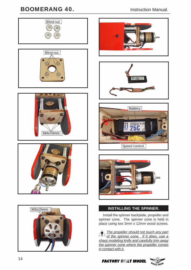
Battery.
Speed control.
Install the spinner backplate, propeller andspinner cone. The spinner cone is held inplace using two 3mm x 12mm wood screws.
The propeller should not touch any partof the spinner cone. If it does, use a
sharp modeling knife and carefully trim awaythe spinner cone where the propeller comesin contact with it.
INSTALLING THE SPINNER.
M4x70mm.
Blind nut.
Blind nut.
M3x15mm.
15
BOOMERANG 40. Instruction Manual.
3. Slide the stabilizer into place in the pre-cut slot in the rear of the fuselage. The stabi-lizer should be pushed firmly against the frontof the slot.
HORIZONTAL STABILIZER.
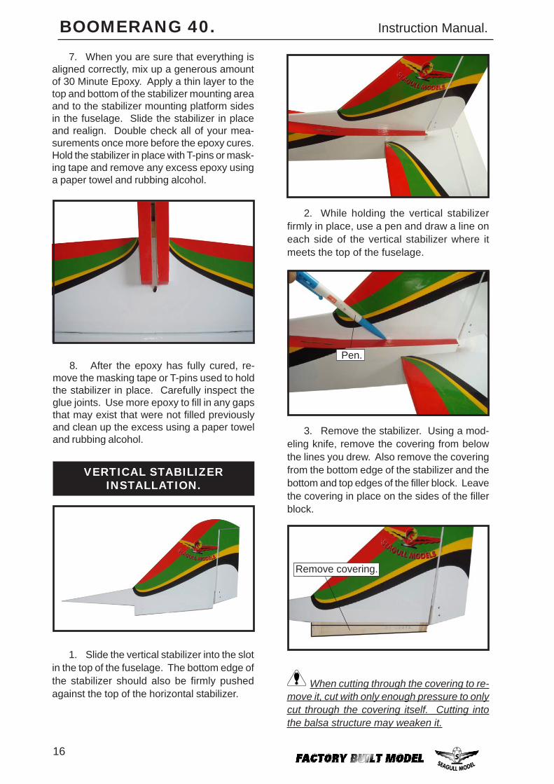
1. Using a ruler and a pen, locate thecenterline of the horizontal stabilizer, at thetrailing edge, and place a mark. Use a tri-angle and extend this mark, from back to front,across the top of the stabilizer. Also extendthis mark down the back of the trailing edgeof the stabilizer.
Draw centerline.
Remove covering.
The top of the stabilizer does not havethe hinge pins exposed.
2. Using a modeling knife, carefully re-move the covering from over the vertical sta-bilizer mounting slot in the top of the fuselage.
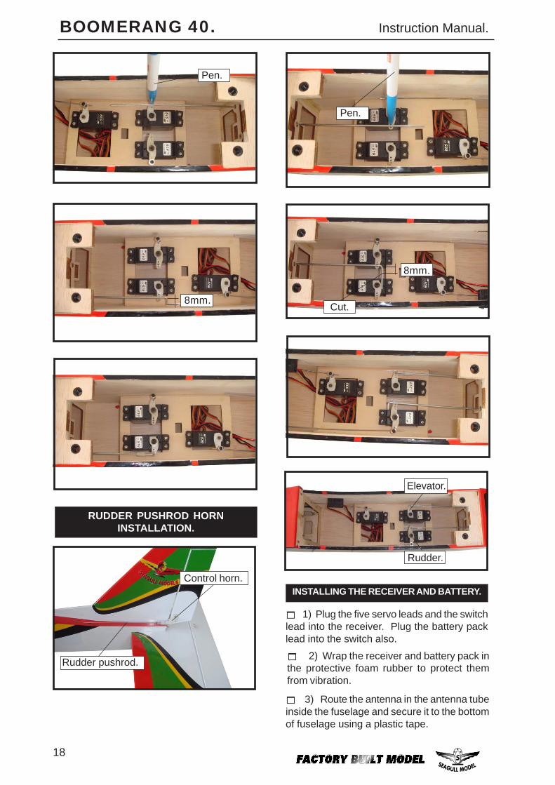
5. Remove the stabilizer. Using the linesyou just drew as a guide, carefully remove thecovering from between them using a model-ing knife.
6. Using a modeling knife, carefully re-move the covering that overlaps the stabilizermounting platform sides in the fuselage. Re-move the covering from both the top and thebottom of the platform sides.
When cutting through the covering to re-move it, cut with only enough pressure
to only cut through the covering itself. Cuttinginto the balsa structure may weaken it.
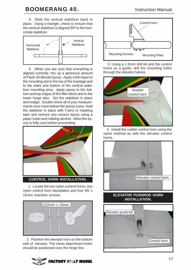
4. With the stabilizer held firmly in place,use a pen and draw lines onto the stabilizerwhere it and the fuselage sides meet. Do thison both the right and left sides and top andbottom of the stabilizer.
Pen.
Remove covering.
16
BOOMERANG 40. Instruction Manual.
2. While holding the vertical stabilizerfirmly in place, use a pen and draw a line oneach side of the vertical stabilizer where itmeets the top of the fuselage.
3. Remove the stabilizer. Using a mod-eling knife, remove the covering from belowthe lines you drew. Also remove the coveringfrom the bottom edge of the stabilizer and thebottom and top edges of the filler block. Leavethe covering in place on the sides of the fillerblock.
When cutting through the covering to re-move it, cut with only enough pressure to onlycut through the covering itself. Cutting intothe balsa structure may weaken it.
Remove covering.
Pen.
1. Slide the vertical stabilizer into the slotin the top of the fuselage. The bottom edge ofthe stabilizer should also be firmly pushedagainst the top of the horizontal stabilizer.
VERTICAL STABILIZERINSTALLATION.
7. When you are sure that everything isaligned correctly, mix up a generous amountof 30 Minute Epoxy. Apply a thin layer to thetop and bottom of the stabilizer mounting areaand to the stabilizer mounting platform sidesin the fuselage. Slide the stabilizer in placeand realign. Double check all of your mea-surements once more before the epoxy cures.Hold the stabilizer in place with T-pins or mask-ing tape and remove any excess epoxy usinga paper towel and rubbing alcohol.
8. After the epoxy has fully cured, re-move the masking tape or T-pins used to holdthe stabilizer in place. Carefully inspect theglue joints. Use more epoxy to fill in any gapsthat may exist that were not filled previouslyand clean up the excess using a paper toweland rubbing alcohol.
17
BOOMERANG 40. Instruction Manual.
CONTROL HORN INSTALLATION.
1. Locate the two nylon control horns, twonylon control horn backplates and four M2 x15mm machine screws.
(2)2mm x 15mm.
4. Slide the vertical stabilizer back inplace. Using a triangle, check to ensure thatthe vertical stabilizer is aligned 90º to the hori-zontal stabilizer.
5. When you are sure that everything isaligned correctly, mix up a generous amountof Flash 30 Minute Epoxy. Apply a thin layer tothe mounting slot in the top of the fuselage andto the sides and bottom of the vertical stabi-lizer mounting area. Apply epoxy to the bot-tom and top edges of the filler block and to thelower hinge also. Set the stabilizer in placeand realign. Double check all of your measure-ments once more before the epoxy cures. Holdthe stabilizer in place with T-pins or maskingtape and remove any excess epoxy using apaper towel and rubbing alcohol. Allow the ep-oxy to fully cure before proceeding.
90º
VerticalStabilizer.Horizontal
Stabilizer.
4. Install the rudder control horn using thesame method as with the elevator controlhorns.
Ruddercontrol horn.
Elevator control horn.
Control Horn.
Mounting Screws. Mounting Plate.
2. Position the elevator horn on the bottomside of elevator. The clevis attachment holesshould be positioned over the hinge line.
3. Using a 1.5mm drill bit and the controlhorns as a guide, drill the mounting holesthrough the elevator halves.
ELEVATOR PUSHROD HORNINSTALLATION.
Elevator pushrod.
Control horn.
18
BOOMERANG 40. Instruction Manual.
Pen.
Control horn.
Rudder pushrod.
RUDDER PUSHROD HORNINSTALLATION.
8mm.
Elevator.
Rudder.
8mm.
Cut.
Pen.
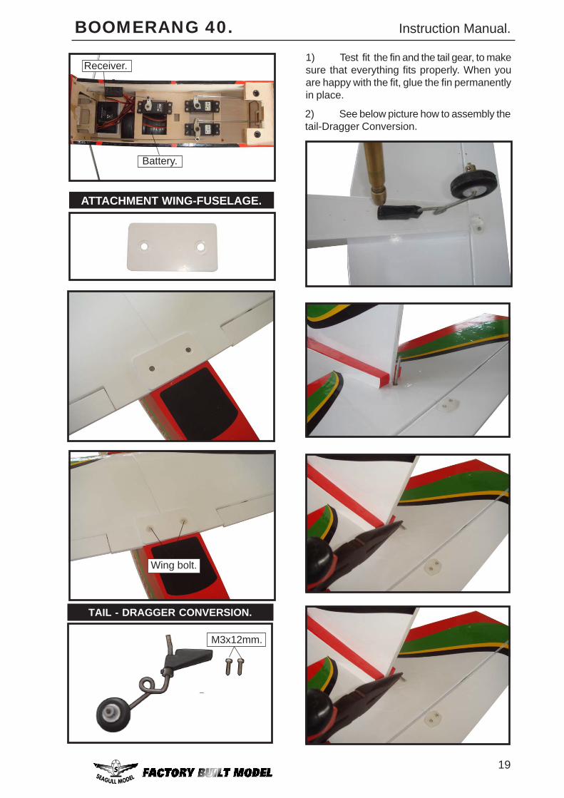
INSTALLING THE RECEIVER AND BATTERY.
1) Plug the five servo leads and the switchlead into the receiver. Plug the battery packlead into the switch also.
3) Route the antenna in the antenna tubeinside the fuselage and secure it to the bottomof fuselage using a plastic tape.
2) Wrap the receiver and battery pack inthe protective foam rubber to protect themfrom vibration.
19
BOOMERANG 40. Instruction Manual.
ATTACHMENT WING-FUSELAGE.
Receiver.
Battery.
Wing bolt.
TAIL - DRAGGER CONVERSION.
M3x12mm.
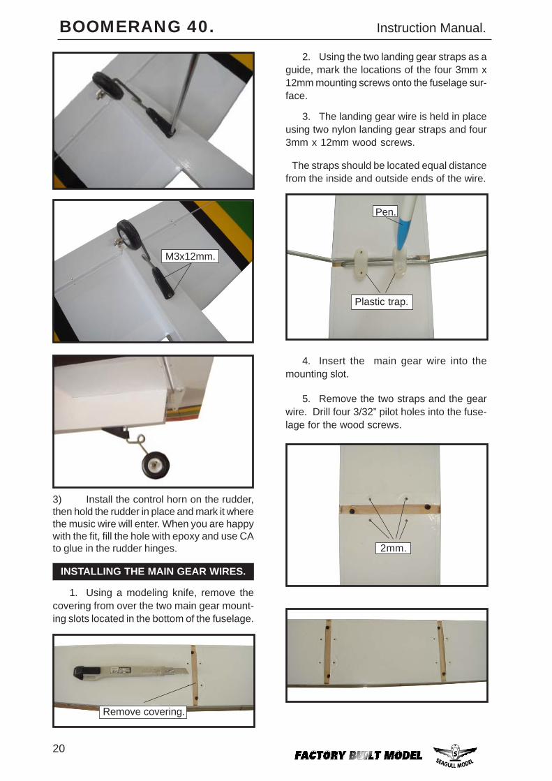
1) Test fit the fin and the tail gear, to makesure that everything fits properly. When youare happy with the fit, glue the fin permanentlyin place.
2) See below picture how to assembly thetail-Dragger Conversion.
20
BOOMERANG 40. Instruction Manual.
M3x12mm.
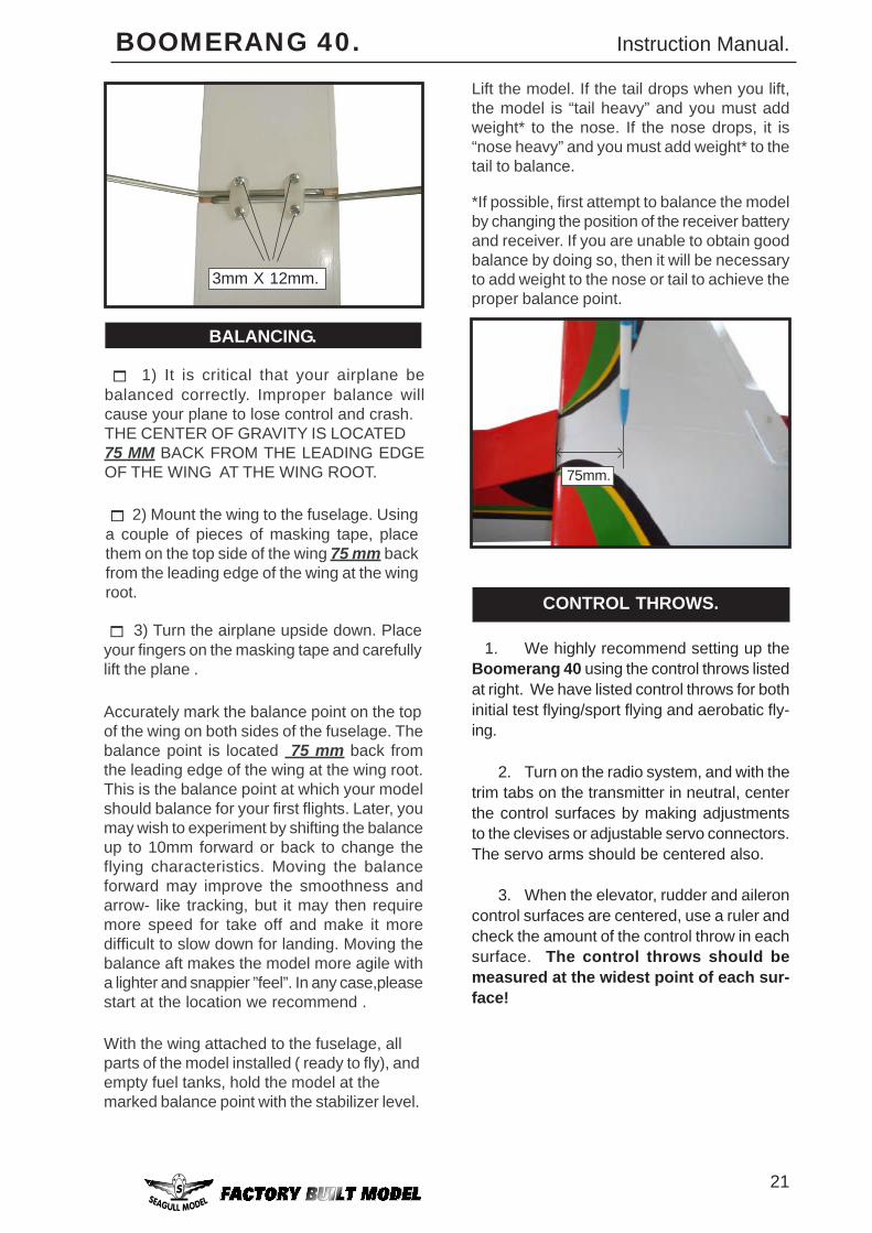
3) Install the control horn on the rudder,then hold the rudder in place and mark it wherethe music wire will enter. When you are happywith the fit, fill the hole with epoxy and use CAto glue in the rudder hinges. 2mm.
1. Using a modeling knife, remove thecovering from over the two main gear mount-ing slots located in the bottom of the fuselage.
2. Using the two landing gear straps as aguide, mark the locations of the four 3mm x12mm mounting screws onto the fuselage sur-face.
Remove covering.
INSTALLING THE MAIN GEAR WIRES.
3. The landing gear wire is held in placeusing two nylon landing gear straps and four3mm x 12mm wood screws.
The straps should be located equal distancefrom the inside and outside ends of the wire.
5. Remove the two straps and the gearwire. Drill four 3/32” pilot holes into the fuse-lage for the wood screws.
Plastic trap.
Pen.
4. Insert the main gear wire into themounting slot.
21
BOOMERANG 40. Instruction Manual.
BALANCING.
CONTROL THROWS.
2. Turn on the radio system, and with thetrim tabs on the transmitter in neutral, centerthe control surfaces by making adjustmentsto the clevises or adjustable servo connectors.The servo arms should be centered also.
3. When the elevator, rudder and aileroncontrol surfaces are centered, use a ruler andcheck the amount of the control throw in eachsurface. The control throws should bemeasured at the widest point of each sur-face!
1. We highly recommend setting up theBoomerang 40 using the control throws listedat right. We have listed control throws for bothinitial test flying/sport flying and aerobatic fly-ing.
3mm X 12mm.
With the wing attached to the fuselage, allparts of the model installed ( ready to fly), andempty fuel tanks, hold the model at themarked balance point with the stabilizer level.
Lift the model. If the tail drops when you lift,the model is “tail heavy” and you must addweight* to the nose. If the nose drops, it is“nose heavy” and you must add weight* to thetail to balance.
*If possible, first attempt to balance the modelby changing the position of the receiver batteryand receiver. If you are unable to obtain goodbalance by doing so, then it will be necessaryto add weight to the nose or tail to achieve theproper balance point.
3) Turn the airplane upside down. Placeyour fingers on the masking tape and carefullylift the plane .
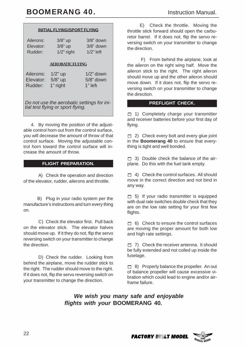
Accurately mark the balance point on the topof the wing on both sides of the fuselage. Thebalance point is located 75 mm back fromthe leading edge of the wing at the wing root.This is the balance point at which your modelshould balance for your first flights. Later, youmay wish to experiment by shifting the balanceup to 10mm forward or back to change theflying characteristics. Moving the balanceforward may improve the smoothness andarrow- like tracking, but it may then requiremore speed for take off and make it moredifficult to slow down for landing. Moving thebalance aft makes the model more agile witha lighter and snappier ”feel”. In any case,pleasestart at the location we recommend .
2) Mount the wing to the fuselage. Usinga couple of pieces of masking tape, placethem on the top side of the wing 75 mm backfrom the leading edge of the wing at the wingroot.
1) It is critical that your airplane bebalanced correctly. Improper balance willcause your plane to lose control and crash.THE CENTER OF GRAVITY IS LOCATED75 MM BACK FROM THE LEADING EDGEOF THE WING AT THE WING ROOT. 75mm.
22
BOOMERANG 40. Instruction Manual.
PREFLIGHT CHECK.
1) Completely charge your transmitterand receiver batteries before your first day offlying.
2) Check every bolt and every glue jointin the Boomerang 40 to ensure that every-thing is tight and well bonded.
3) Double check the balance of the air-plane. Do this with the fuel tank empty.
4) Check the control surfaces. All shouldmove in the correct direction and not bind inany way.
5) If your radio transmitter is equippedwith dual rate switches double check that theyare on the low rate setting for your first fewflights.
6) Check to ensure the control surfacesare moving the proper amount for both lowand high rate settings.
7) Check the receiver antenna. It shouldbe fully extended and not coiled up inside thefuselage.
We wish you many safe and enjoyableflights with your BOOMERANG 40.
8) Properly balance the propeller. An outof balance propeller will cause excessive vi-bration which could lead to engine and/or air-frame failure.
F) From behind the airplane, look atthe aileron on the right wing half. Move theaileron stick to the right. The right aileronshould move up and the other aileron shouldmove down. If it does not, flip the servo re-versing switch on your transmitter to changethe direction.
4. By moving the position of the adjust-able control horn out from the control surface,you will decrease the amount of throw of thatcontrol surface. Moving the adjustable con-trol horn toward the control surface will in-crease the amount of throw.
INITIAL FLYING/SPORT FLYING
Ailerons: 3/8” up 3/8” downElevator: 3/8” up 3/8” downRudder: 1/2” right 1/2” left
AEROBATIC FLYING
Ailerons: 1/2” up 1/2” downElevator: 5/8” up 5/8” downRudder: 1” right 1” left
Do not use the aerobatic settings for ini-tial test flying or sport flying.
E) Check the throttle. Moving thethrottle stick forward should open the carbu-retor barrel. If it does not, flip the servo re-versing switch on your transmitter to changethe direction.
FLIGHT PREPARATION.
C) Check the elevator first. Pull backon the elevator stick. The elevator halvesshould move up. If it they do not, flip the servoreversing switch on your transmitter to changethe direction.
D) Check the rudder. Looking frombehind the airplane, move the rudder stick tothe right. The rudder should move to the right.If it does not, flip the servo reversing switch onyour transmitter to change the direction.
A) Check the operation and directionof the elevator, rudder, ailerons and throttle.
B) Plug in your radio system per themanufacture’s instructions and turn every thingon.