Embed Size (px)
Citation preview

SPOT DEM Precision Product description
Version1.0 - April 1st, 2006
This edition supersedes previous versions

Spot DEM Precision product description V1.0; April 1st, 2006 1 / 18
Acronyms
DIMAP Digital Image MAP (encapsulation format supporting data display with an Internet browser)
DTED Digital Terrain Elevation Data
DXF Drawing Exchange Format (AutoCAD)
HRS High Resolution Stereoscopic (SPOT 5 sensor)
JPEG, JPG Joint Photographic Expert Group
Mb Megabytes
DTM
DEM
Digital Terrain Model
Digital Elevation Model
SRTM Shuttle Radar Topographic Mission
SVG Scalable Vector Graphics
TIFF - GeoTIFF Tag Image File Format – GeoTIFF is the geocoded version of TIFF
XML eXtensible Markup Language – Format of certain files in DIMAP

Spot DEM Precision product description V1.0; April 1st, 2006 2 / 18
Contents
1 Introduction ...........................................................................................................................................3
2 Product features.....................................................................................................................................4 2.1 SPOT DEM Precision contents ................................................................................................................4
2.1.1 Data framing...........................................................................................................................................................4 2.1.2 Coverage.................................................................................................................................................................4 2.1.3 Quality layers .........................................................................................................................................................4 2.1.4 Product format ........................................................................................................................................................4 2.1.5 Source data naming ................................................................................................................................................4
2.2 SPOT DEM Precision feasibility..............................................................................................................5 3 SPOT DEM Precision layer specification ............................................................................................6
3.1 DEM layer..................................................................................................................................................6 3.1.1 Data format and encoding.......................................................................................................................................6 3.1.2 Framing ..................................................................................................................................................................6
3.1.2.1 GeoTIFF option ............................................................................................................................................6 3.1.2.2 DTED option.................................................................................................................................................6
3.1.3 Datum.....................................................................................................................................................................7 3.1.4 DEM post-spacing ..................................................................................................................................................7 3.1.5 DEM geometric accuracy .......................................................................................................................................7 3.1.6 Landform characteristics ........................................................................................................................................8 3.1.7 Uniformity and continuity within a SPOT DEM Precision product.......................................................................8
3.2 Quality layer ..............................................................................................................................................9 3.2.1 Source data footprint and type................................................................................................................................9 3.2.2 SPOT DEM Precision quality masks......................................................................................................................9 3.2.3 Quality control masks of the Reference3D source data used for generation ........................................................11
3.3 Metadata ..................................................................................................................................................11 4 SPOT DEM Precision product structure............................................................................................12
4.1 File tree.....................................................................................................................................................12 4.2 File formats ..............................................................................................................................................13 4.3 Style sheets ...............................................................................................................................................14
5 SPOT DEM Precision sizes.................................................................................................................15
6 Annex 1 ................................................................................................................................................17

1 Introduction
This document describes the specifications and format for the SPOT DEM Precision product, fully derived from the Reference3D database. The Reference3D database, which chiefly comprises SPOT 5 HRS data covering pre-defined regions of interest, is planned to cover at least 30 million square kilometres by June 2008. Reference3D is co-produced by Spot Image and IGN, France’s national survey and mapping agency. As of April 1st, 2006, more than 15 millions km² of Reference3D tiles are available for SPOT DEM Precision products generation.
SPOT DEM Precision comprises several registerable layers of data:
- A 16 bits-signed DEM in GeoTIFF format (DTED2 as an option) - full layers of quality and traceability data
These layers are encapsulated within a DIMAP profile for display using an Internet browser.
SPOT DEM Precision is the sole DEM on the market providing detailed information on both the identification and localisation of residual errors (artefacts) inherent to automatic correlation computation. This capacity proves SPOT DEM Precision to be the ideal tool for UAV, missiles and aircrafts on-board databases, as well as mission planning for the MODs and armament industry.
1 328 Reference3D available tiles as of April 1st
Spot DEM Precision product description V1.0; April 1st, 2006 3 / 18
2 Product features
2.1 SPOT DEM Precision contents SPOT DEM Precision comprises the following layers of information:
- A DTED2-class DEM, exclusively derived from existing Reference3D tiles - Layers of quality and traceability information
2.1.1 Data framing SPOT DEM Precision is provided by square kilometers, according to the framing provided by the customer.
2.1.2 Coverage
The HRS instrument cannot guarantee complete coverage of some zones due to weather conditions, stereopair correlation limits due to the landscape, and the inherent limits of the sensor when imaging very mountainous terrain (B/H ratio of 0.8). Gaps in DEMs therefore will be filled locally by interpolation or with other source data.
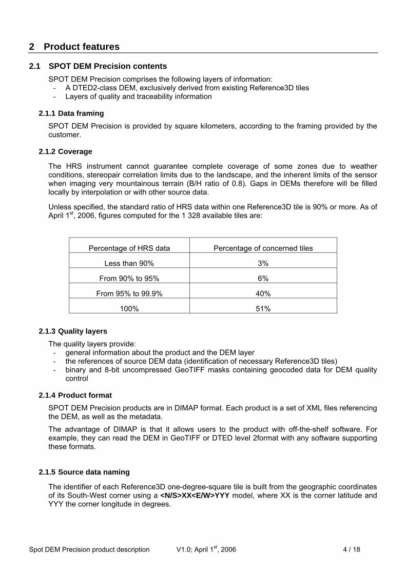
Unless specified, the standard ratio of HRS data within one Reference3D tile is 90% or more. As of April 1st, 2006, figures computed for the 1 328 available tiles are:
Percentage of HRS data Percentage of concerned tiles
Less than 90% 3%
From 90% to 95% 6%
From 95% to 99.9% 40%
100% 51%
2.1.3 Quality layers The quality layers provide:
- general information about the product and the DEM layer - the references of source DEM data (identification of necessary Reference3D tiles) - binary and 8-bit uncompressed GeoTIFF masks containing geocoded data for DEM quality
control
2.1.4 Product format SPOT DEM Precision products are in DIMAP format. Each product is a set of XML files referencing the DEM, as well as the metadata.
The advantage of DIMAP is that it allows users to the product with off-the-shelf software. For example, they can read the DEM in GeoTIFF or DTED level 2format with any software supporting these formats.
2.1.5 Source data naming
The identifier of each Reference3D one-degree-square tile is built from the geographic coordinates of its South-West corner using a <N/S>XX<E/W>YYY model, where XX is the corner latitude and YYY the corner longitude in degrees.
Spot DEM Precision product description V1.0; April 1st, 2006 4 / 18

2.2 SPOT DEM Precision feasibility
SPOT DEM Precision is fully derived from existing Reference3D product. As of April 1st, 2006, more than 15 millions km² are available off-the-shelf, enabling rapid generation of SPOT DEM Precision (see map in §1). More than 100 millions km² of qualified HRS data are though available worldwide for SPOT DEM Precision production upon request. The map found below highlights in red and orange the areas where SPOT DEM Precision generation can be initiated.
Tiles available on 01/04/2006
% of qualified HRS data per tile
Spot DEM Precision product description V1.0; April 1st, 2006 5 / 18

3 SPOT DEM Precision layer specification
3.1 DEM layer 3.1.1 Data format and encoding
The DEM layer of the SPOT DEM Precision product contains elevation values in metres, encoded as 16-bit signed integers with the most significant bit first (Intel coding). When generated in DTED format, this layer exclusively derived from Reference3D source data is fully compliant with the DTED level 2 standards. The –32767 value in the DTED format that indicates a null value is also used whenever outside of the Area of Interest (AOI) provided by the customer.
3.1.2 Framing Depending on the selected generation format (GeoTIFF or DTED) a SPOT DEM Precision product may comprise on or more products covering the AOI (see below).
3.1.2.1 GeoTIFF option
Customer’s area of Interest Provided product
Bounding box
AOI AOI
3.1.2.2 DTED option Customer’s area of Interest
Provided products
AOI
1°
1°
Spot DEM Precision product description V1.0; April 1st, 2006 6 / 18

Spot DEM Precision product description V1.0; April 1st, 2006 7 / 18
3.1.3 Datum The vertical datum is EGM 96.
On request, SPOT DEM Precision values can be provided in: - Geographic coordinates with respect to WGS84 - Cartographic coordinates in UTM WGS84 system, within the (one of the) applicable UTM
zone
Other cartographic systems can be used if all necessary conversion parameters between these systems and UTM WGS84 are provided by the customer. In such a case, no specifications are guaranteed by Spot Image.
3.1.4 DEM post-spacing Depending on the chosen referential system, the post-spacing of SPOT DEM Precision products can be provided in:
- Cartographic referential: resampled with a constant post spacing of 20 metres or - In accordance with the DTED level 2 standard (Geographic referential), as shown in the table
below:
Tile latitude Latitude post spacing
Longitude post spacing
Nodes
0° to 50° North or South 1 arc second 1 arc second 3601 * 3601 50° to 70° North or South 1 arc second 2 arc seconds 3601 * 1801 70° to 75° North or South 1 arc second 3 arc seconds 3601 * 1201 75° to 80° North or South 1 arc second 4 arc seconds 3601 * 901 80° to 90° North or South 1 arc second 6 arc seconds 3601 * 601
3.1.5 DEM geometric accuracy The DEM accuracy specifications below apply to DEMs generated from HRS imagery and not to DEMs derived from external sources.
- Absolute elevation accuracy
linear error with respect to EGM96 (confidence level 90%) flat or rolling terrain (slope ≤ 20 %)....................................................... 10 m hilly terrain (20 % < slope ≤ 40 %) ........................................................ 18 m mountainous terrain (slope > 40 %)...................................................... 30 m
- Absolute planimetric accuracy circular error with respect to WGS84 (confidence level 90%) .............. 15 m
- Relative elevation accuracy within tile linear error (confidence level 90%) flat or rolling terrain (slope ≤ 20 %)....................................................... 5 m hilly terrain (20 % < slope ≤ 40 %) ........................................................ 15 m mountainous terrain (slope > 40 %)...................................................... 28 m
- Relative planimetric accuracy within tile circular error (confidence level 90%) .................................................... 8 m

Spot DEM Precision product description V1.0; April 1st, 2006 8 / 18
3.1.6 Landform characteristics
Landform characteristics supplement geometric accuracy specifications, in particular for local features in a DEM. Special attention is paid to the following features, which must be visible in the DEM:
Critical landforms other than islands (confidence level 96%) - features larger than 200 m by 100 m - and an elevation difference with the surrounding terrain greater than 30 m
Islands (confidence level 99%) - islands larger than 200 m by 100 m - and an elevation difference with the surrounding water greater than 15 m OR - islands larger than 300 m by 300 m
Watersheds and drains (confidence level 96%) - Drains wider than 150 m
Cliffs (confidence level 99%) - longer than 200 m - higher than 30 m with a local slope greater than 80%
Artefacts - artefacts larger than 300 m by 200 m - and an elevation error greater than 40 m must cover less than 1% of the 1° x 1° square
Water bodies Water bodies are:
- oceans and open seas with an elevation of 0 m - lakes of constant elevation where they are more than 600 m across
Landscapes surrounding water bodies are not artificially raised.
3.1.7 Uniformity and continuity within a SPOT DEM Precision product No elevation discontinuities exhibiting a bias greater than 2 m are accepted within a SPOT DEM Precision product.
3.2 Quality layer
3.2.1 Source data footprint and type SPOT DEM Precision contains the references and ground footprints of source data, in polygon form in DXF and SVG formats.
3.2.2 SPOT DEM Precision quality masks
Performance mask MPL
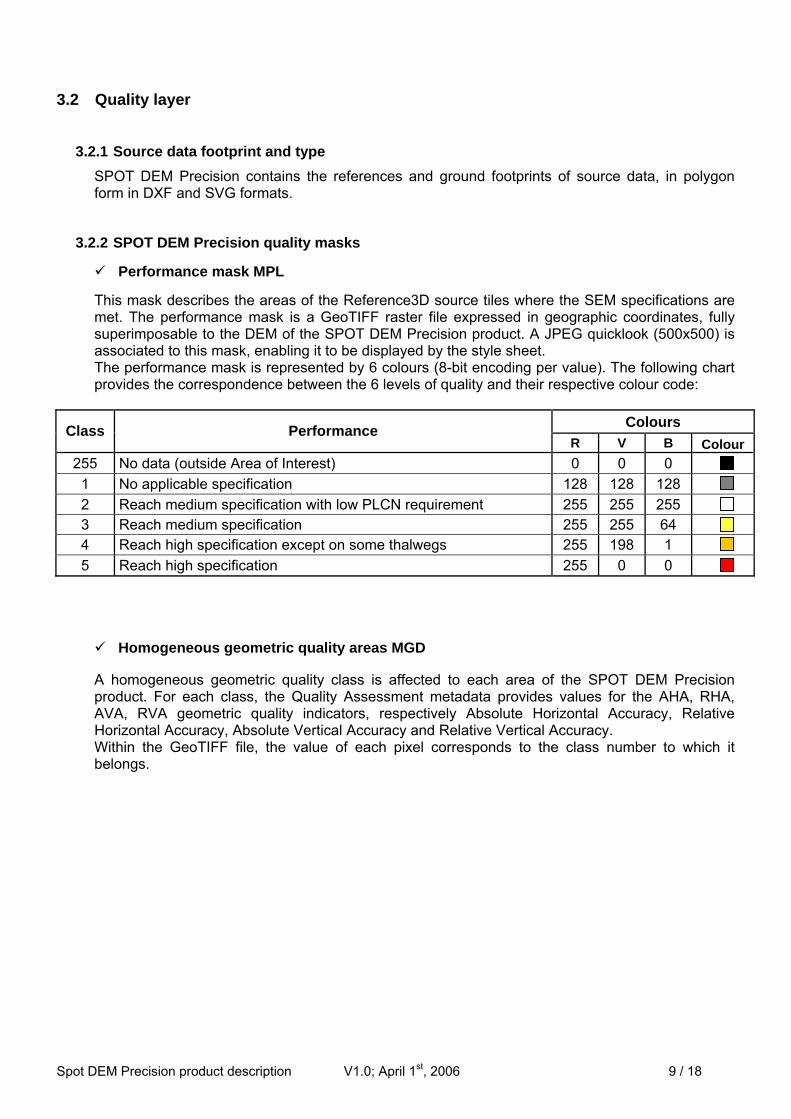
This mask describes the areas of the Reference3D source tiles where the SEM specifications are met. The performance mask is a GeoTIFF raster file expressed in geographic coordinates, fully superimposable to the DEM of the SPOT DEM Precision product. A JPEG quicklook (500x500) is associated to this mask, enabling it to be displayed by the style sheet. The performance mask is represented by 6 colours (8-bit encoding per value). The following chart provides the correspondence between the 6 levels of quality and their respective colour code:
Colours Class Performance R V B Colour
255 No data (outside Area of Interest) 0 0 0
1 No applicable specification 128 128 128 2 Reach medium specification with low PLCN requirement 255 255 255 3 Reach medium specification 255 255 64 4 Reach high specification except on some thalwegs 255 198 1 5 Reach high specification 255 0 0
Spot DEM Precision product description V1.0; April 1st, 2006 9 / 18
Homogeneous geometric quality areas MGD
A homogeneous geometric quality class is affected to each area of the SPOT DEM Precisiproduct. For each class, the Quality Assessment metadata provides values for the AHA, RHAVA, RVA geometric quality indicators, respectively Absolute Horizontal Accuracy, RelatiHorizontal Accuracy, Absolute Vertical Accuracy and Relative Vertical Accuracy. Within the GeoTIFF file, the value of each pixel corresponds to the class number to whichbelongs.
on A, ve
it

The following chart provides the correspondence between the quality classes and their respective colour code:
Quality classes Colours Index AHA RHA AVA RVA R V B Colour
0 0 0 0 0 0 0 0
1 13 8 10 5 0 0 225
2 13 8 10 15 30 30 225
3 13 8 10 28 60 60 95
4 13 8 18 5 180 100 65
5 13 8 18 15 210 130 35
6 13 8 18 28 240 160 5
7 13 8 30 5 195 195 60
8 13 8 30 15 225 225 30
9 13 8 30 28 255 255 0
10 15 10 12 7 0 255 0
11 15 10 12 18 30 245 20
12 15 10 12 35 90 235 40
13 15 10 22 7 120 225 60
14 15 10 22 18 150 215 80
15 15 10 22 35 180 205 100
16 15 10 35 7 210 195 120
17 15 10 35 18 240 185 140
18 15 10 35 35 255 175 160
19 30 18 25 15 255 0 0
20 30 18 25 30 245 30 20
21 30 18 25 40 235 90 40
22 30 18 40 15 225 120 60
23 30 18 40 30 215 150 80
24 30 18 40 40 205 180 100
25 30 18 50 15 195 210 120
26 30 18 50 30 185 240 140
27 30 18 50 40 175 255 160
Spot DEM Precision product description V1.0; April 1st, 2006
Water mask (MWa) Contains flat maritime or inland water bodies visible in the Reference3D orthoiIt is produced by manual delineation with an orthoimage underlay. The significant in zones that are zero-rated in the MCl mask (snow or cloud).
0: sea or water body more than 600 m across 1: no water
Exogenous mask (MEx) Indicates areas computed using external data. It is delineated manually.
0: exogenous data 1: no exogenous data
10 / 18
mages source data. water mask is not

3.2.3 Quality control masks of the Reference3D source data used for generation
Masks are 1-bit GeoTIFF files containing geographic coordinates, with the same post spacing as the DEM. They are provided on the entire footprint of the square-degree framing source data. Full description of these masks is to be found in Annex 1.
3.3 Metadata
Reference3D source data A link towards the Reference3D source data used for the SPOT DEM Precision product is included. These source data remain within their native projection system (WGS84).
HRS data strip The following metadata are provided for each HRS data strip used to produce a source tile:
Block triangulation Tie points:
number of points mean of planimetric residuals (in 10-m pixels) standard deviation of planimetric residuals (in 10-m pixels)
Z points: number of points used mean of Z residuals (in metres) standard deviation of Z residuals (in metres)
DEM number of rows/columns coordinates of 4 corners post spacing
DEM derived from HRS data strips merged to produce tile mean of elevation differences in overlap areas standard deviation of elevation differences in overlap areas
Exogenous data Source Rotation/translation
General information Geodetic reference system Producer reference
Spot DEM Precision product description V1.0; April 1st, 2006 11 / 18

4 SPOT DEM Precision product structure
4.1 File tree Files containing data for SPOT DEM Precision covering data source N26E057 are organized according to the tree below:
File names are eight characters and file extensions three characters maximum, in accordance with the ISO 9660 standard.
Spot DEM Precision product description V1.0; April 1st, 2006 12 / 18
Spot DEM Precision product description V1.0; April 1st, 2006 13 / 18
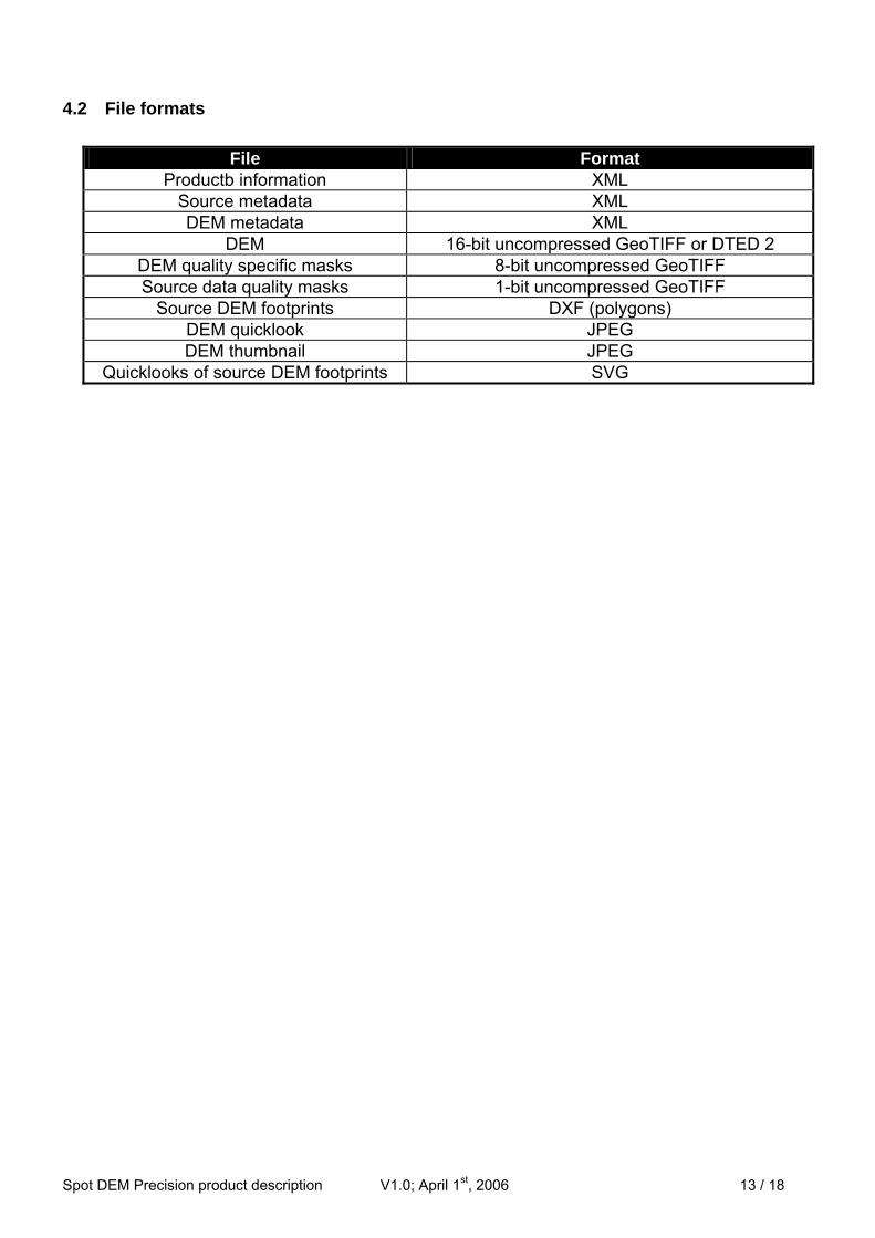
4.2 File formats
File Format Productb information XML
Source metadata XML DEM metadata XML
DEM 16-bit uncompressed GeoTIFF or DTED 2 DEM quality specific masks 8-bit uncompressed GeoTIFF Source data quality masks 1-bit uncompressed GeoTIFF
Source DEM footprints DXF (polygons) DEM quicklook JPEG DEM thumbnail JPEG
Quicklooks of source DEM footprints SVG

4.3 Style sheets Every SPOT DEM Precision product in DIMAP format comes with several XSL style sheets that allow its main features to be displayed with an Internet browser.
An example style sheet is shown below:
Characteristics of the style sheets are given as an indication and are subject to change without notice.
Spot DEM Precision product description V1.0; April 1st, 2006 14 / 18

Spot DEM Precision product description V1.0; April 1st, 2006 15 / 18
5 SPOT DEM Precision sizes
The appropriate maximum file sizes for a SPOT DEM Precision product located at the Equator can be estimated as shown below. The largest files will be those constituting tiles at latitudes below 50°. File sizes for all other products will decrease significantly as latitude increases.
GeoTIFF option (without reprojection) 1° x 1° 30' x 30' 15' x 15'
20 m constant post-spacing Encoding
(Nbits) 12 000 km² 3 000 km² 750 km²
DEM 16 26 Mo 7 Mo 2 Mo Specific SPOT DEM Precision masks (MGD, MPL, MWA, MEX)
8 52 Mo 13 Mo 3 Mo
Source data masks (MCL, MCO, MEX, MME, MQU, MRE, MVA, MWA)
1 11 Mo 3 Mo 1 Mo
DTED option 1° x 1° 30' x 30' 15' x 15'
1 sec arc post-spacing Encoding
(Nbits) 12 000 km² 3 000 km² 750 km²
DEM 16 26 Mo 7 Mo 2 Mo Specific SPOT DEM Precision masks (MGD, MPL)
8 26 Mo 7 Mo 2 Mo
Source data masks (MCL, MCO, MEX, MME, MQU, MRE, MVA, MWA)
1 11 Mo 3 Mo 1 Mo

Spot DEM Precision product description V1.0; April 1st, 2006 16 / 18

Spot DEM Precision product description V1.0; April 1st, 2006 17 / 18
6 Annex 1
Quality control masks of the Reference3D source data used for generation (see Reference3D Product Description for detailed information).
Masks are 1-bit GeoTIFF files containing geographic coordinates, with the same post spacing as the DEM. They are provided on the entire footprint of the square-degree framing source data.
Water mask (MWa) Contains flat maritime or inland water bodies visible in Reference3D orthoimages. It is produced by manual delineation with an orthoimage underlay. The water mask is not significant in zones that are zero-rated in the MCl mask (snow or cloud).
0: sea or water body more than 600 m across 1: no water
DEM merge mask (MMe) Contains areas derived from a single DEM and is generated automatically.
0: no DEM or one single DEM used 1: at least two merged DEMS
Correlation mask (MCo) Generated by a 50% thresholding of CCs.
0: confidence coefficient less than 50% 1: confidence coefficient greater than or equal to 50%
Cloud/snow mask (MCl) Describes the cloud- and snow-covered areas which remain in the Reference3D orthoimage. It is delineated manually using the orthoimage. On snow-covered areas, this mask only describes areas with out-of-specifications DEM.
0: cloud or snow 1: no cloud or snow
Exogenous mask (MEx) Indicates areas computed using external data. It is delineated manually.
0: exogenous data 1: no exogenous data
Regulation mask (MRe) Contains DEM artefacts corrected without external data. Water bodies in the MWa mask are not included.
0: artefacts detected and corrected 1: no artefacts
Visual control mask (MQu) Generated by a visual examination of the final DEM. This mask identifies areas in the DEM deemed by the operator not to meet specifications.
0: data do not meet Reference3D specifications 1: data meet Reference3D specifications