Embed Size (px)
Citation preview

Graham Betts and Bill Gordon
Module 11 Pumps plumbing and componentsHow they can work together
SPRAY APPLICATION MANUAL FOR GRAIN GROWERS
PAGE 2MODULE 11 Pumps plumbing and components
Key points
bull The correct plumbing will allow all of the components in the spray system to operate as they are intended
bull Careful consideration must be given to the selection of the pump plumbing valves and other components so they match all of the spray applications the operator plans to make
bull Before the purchase or installation of new components the operator shouldconsiderwhattherangeofflowratesthrougheachcomponentwill need to be
bull The operator should consider how heshe will access maintain and calibrate all of the components on the sprayer before they are installed
bull It is important to consider how various components of the spray system such as the main tank can be isolated from the rest of the spray system to provide safe access for maintenance and inspections
Acronyms used in this module
DIN = Deutsches Institut fuumlr Normung (DIN) the organisation for German national standards
ID = inside dimension
ISO = International Organization for Standardization
OD = outside dimension
PTO = power take-off
RHS = rectangular hollow section
RPM = revolutions per minute
PAGE 3PAGE 3MODULE 11 Pumps plumbing and components MODULE 11 Pumps plumbing and components
1 Introduction
For spraying the principle of using a pump to transfer liquid from the spray tank to the nozzles remains the same as it has for decades but the options available to control the flow to the boom and the output from the nozzles has advanced enormously in recent years
Plumbing has become increasingly important as spray application equipment has increased in size and complexity There are many options available so the operator must ensure that the plumbing and components chosen are suitable for the task and correctly installed to allow the sprayer to perform as intended
There are entire books written about sprayer pumps and components so the aim of this module is not to lsquoreinvent the wheelrsquo but to provide information and tips on how the components can best work together along with how to best install them into the spraying system to ensure it continues to operate efficiently and effectively
The major components of the spraying system and considerations discussed in this module are outlined in Figure 1
Main tank
Flush tank
Filtration
Agitation
Pump(s)
Filtration
Regulation and valves Bypassrelief
Boom and sections Re-circulation
Nozzle bodies
Things for the operator to considerMain tank shape sumps isolationFlush tank size relative to main tankFiltration suction pressure section nozzlesPumps diaphragm centrifugalRegulation pressure relief bypass Agitation sparge venturiValves two way three wayRe-circulation manual or electricNozzle bodies wet boom dry boom
Figure 1 Overview of the major components of the plumbing system
PAGE 4MODULE 11 Pumps plumbing and components
2 The main spray tank
The most common materials that spray tanks are manufactured from are stainless steel polypropylene and fibreglass (with a shiny layer of glass on the inside no fibre showing) Of the three stainless steel tanks will increase the sprayerrsquos weight but will also tend to hold their shape (and known volume) better than the other materials
The most important requirements of the main spray tank are that there are no internal ledges and that it is shaped so it is relatively easy to keep products agitated and in solution The main tank should also have a tapered bottom with a main and secondary sump
Product can become trapped unless it can circulate freely in the tank
Photo Graham Betts
Residue on tank ledges
PAGE 5PAGE 5MODULE 11 Pumps plumbing and components MODULE 11 Pumps plumbing and components
21 Main sump and secondary sump The main sump needs to be in the lowest point of the tank and positioned so that the sprayer frame does not prevent the installation of a tank outlet at the bottom of the sump (not at the side of the sump)
The secondary sump is the shape of the tank floor which should taper from all corners and edges of the tank into the main sump There should only be one hole at the base of the tank (sump) for the outlet An additional hole should only be installed at the end of an elongated tank if Venturi agitation is to be fitted
All other plumbing and return hoses to the tank including the plumbing for sparge agitators should be installed into the top of the tank This will help to reduce potential problems if fittings start to leak and will allow the tank to be isolated from other components This is particularly important if you need to complete work on the plumbing while the tank is full of water or product and to help with troubleshooting or cleaning filter screens
A tank outlet that does not move when installing fittings and allows the tank to totally drain is very practical eg a Banjoreg Bottom Drain manifold bolted tank fitting It is very important to have an anti-vortex fitting in any tank outlet to reduce the chance of the pump sucking air
TIPSbull It is important to use a bottom drain tank outlet eg Banjoreg Poly
Bolted Bottom Drain Tank flanges will allow the tank to be drained completely
bull Install an anti-vortex fitting in the top of the tank outlet to help reduce the chance of the pump sucking air when the tank is low
bull Install a manual ball valve on the tank outlet so the main spray tank can be isolated if there is a problem with the sprayer
bull It is ideal to use lsquoflangersquo or lsquofly-nut-and-tailrsquo fittings to make installation adjustment maintenance servicing and repairs easier For example removing a centrifugal pump to be repaired would be very easy if the pump inlet and outlet fittings are flange or nut-and-tail fittings Ideally these fittings could be used at any location on the sprayer on components that may need to be serviced adjusted or replaced
PAGE 6MODULE 11 Pumps plumbing and components
3Theflushtank
The flush tank should have a capacity that is at least 10 per cent of the capacity of the main tank
It is ideal if the flush tank has its own fill hose from the fresh-water source to reduce the chance of contamination along with a lsquoone-wayrsquo or lsquocheckrsquo valve in the suction line so mixed product cannot move from the main spray tank into the flush tank
Flush tanks are very important for being able to easily flush the pump spray components and nozzles in the field especially if the main spray tank has not been emptied
4 Hand-wash tank
The hand-wash tank (clean water) must be independently plumbed so there is no way it can become contaminated It should have a dedicated fresh water supply fitting that is different to any of the other liquid connections on the sprayer
Carefully consider the volume of water this tank will hold many safety data sheets state that eyes must be flushed with running water for 10 to 15 minutes if product accidently splashes into them It is also ideal to have a soap dispenser next to the hand wash container
PAGE 7PAGE 7MODULE 11 Pumps plumbing and components MODULE 11 Pumps plumbing and components
5 Filtration
Filtration is critical for protecting the sprayerrsquos components and to reduce the potential for nozzle blockages Generally filters are placed before the pump (suction) after the pump (pressure) and before the nozzles (often on boom sections)
There is an ISO standard for the colour of filter screens (related to their mesh size) but unfortunately not all manufacturers use this ISO colour code When ordering a filter it is itherefore mportant to state the mesh size required for the screen not just the colour
Different brands of filter screens are not always the same colour for the same mesh size
Source TeeJetreg
Exampleoffilterscreen
Table 1 The ISO colour code for filter mesh sizes
ISO colour code
Brown red Red Blue Yellow Green Grey (non-ISO)
Orange Pink
Mesh size 16 32 50 80 100 120 150 200
TIPbull Ideally filters should be located where they are easy to access
Locate filter bowls facing downwards and have a manual ball valve on the bowl so the filter is easier to service
PAGE 8MODULE 11 Pumps plumbing and components
51SuctionfiltersThe suction filter is located between the tank outlet and the pump
Suction filters for centrifugal pumps should ideally have a 16-mesh screen or similar which is the most appropriate filter screen size to reduce the chance of any foreign material getting caught in the pumprsquos impeller
Suction filters for diaphragm pumps should ideally have a 30 or 50-mesh screen which are the most appropriate filter screen sizes to protect positive-displacement pumps
52PressurefiltersIdeally the main pressure filter will be installed after the pump but before any of the plumbing components (such as the flow meter and regulating valves)
The main pressure filter should have either 80 or 100-mesh screens which are suitable for both centrifugal and diaphragm pumps It is important to have a pressure-relief valve installed between the pump and main pressure filter when using diaphragm pumps
53Boom-linefiltersBoom-line filters should also have 80 or 100-mesh screens However the mesh size can be changed to suit the nozzle orifice size or formulation type according to the recommendations on the product label
It is best to mount the boom-line filters out on the boom sections They should be plumbed into the spray line at a point as close as practical to where the spray line connects to the boom line
54NozzlefiltersThe mesh size for nozzle filter screens where fitted should match the nozzle orifice size Most nozzle manufacturers will recommend filter sizes to match particular nozzles
Nozzlefilters
Installing boom section filters may be more useful than using nozzle filters
Photo TeeJetreg
PAGE 9PAGE 9MODULE 11 Pumps plumbing and components MODULE 11 Pumps plumbing and components
For most situations it may be preferable that nozzle filters are not installed Generally if there is a problem with products blocking nozzles the source of the problem will be filtration upstream from the nozzles
Nozzle filters can accumulate material on the filter screen due to the low liquid flow rates that occur through a single nozzle At low flow rates the filter screen can strip components out of the formulation (detectable as a film on the screen) This generally does not occur when the same mesh-size screen is used on the boom filters due to the higher flow rates of liquid that will flow to a whole boom section compared to a single nozzle
From the operatorrsquos perspective it may be better to have a blocked nozzle that can be easily seen rather than a nozzle that has restricted the flow due to a partially blocked nozzle filter
TeeJetregfilterbowlwiththreadatbase
TIPSbull The main reasons for having a suction filter on a centrifugal pump are
to protect the pump by taking coarse foreign matter out of the spray solution and to reduce the amount of work the main pressure filter has to do
bull You may need to match the mesh size of the pressure filter screen to the product being used according to information on the product label or to the nozzle orifice size
bull All filters should be mounted so the filter bowl is facing down This way any foreign material falls out when the bowl is removed It is practical to have a manual ball valve at the base of the filter bowl so the filter can be flushed clean without the bowl having to be removed
bull Have a full set of gaskets or O-rings on hand Operators can waste a lot of time trying to install filter bowls with swollen gaskets or O-rings It is useful to place swollen O-rings and gaskets in direct sunlight for several hours (or days) to see if they shrink back to their normal size
Threaded filter bowls allow a ball valve to be installed for flushing the filter
Teejetreg image library
PAGE 10MODULE 11 Pumps plumbing and components
6 Pumps
The most common types of pumps used on sprayers are diaphragm pumps (positive displacement) centrifugal pumps (non-positive displacement) and to a lesser extent roller pumps
Before selecting a pump for the sprayer the operator needs to know what the expected range of flow rates and operating pressures are likely to be After establishing this the operator should carefully examine each pumprsquos performance curve (which shows the pumprsquos flow rate at different pressures) to see which model suits their requirements
Evaluating the performance curve is particularly important when considering purchasing a centrifugal pump or a 12-volt diaphragm pump
The main factors to look at when choosing between diaphragm and centrifugal pumps are the operating pressure required by the nozzles you have chosen to use and the total volume required (eg for the boom and for agitation)
61 Diaphragm pumps Diaphragm pumps are good for maintaining the flow rate (litres per minute) across the entire pressure range the pump is rated for For example the same diaphragm pump can deliver 170Lmin at 20 bar pressure and 165Lmin at 150 bar pressure
Diaphragm pumps are designed to operate at either 540 RPM or 1000 RPM depending on the make and model of the pump and may be PTO-driven or hydraulically driven
Ar150 diaphragm pump
Diaphragm pumps can maintain pressure over their range of flow
Photo TeeJetreg
For more information on howdifferentpump types work go to sprayers101compumps-for-applying-crop-protection-products
Determining pump capacity ndash diaphragm pump example
PAGE 11PAGE 11MODULE 11 Pumps plumbing and components MODULE 11 Pumps plumbing and components
There will be an impact of the RPM on pump performance and output For example the same diaphragm pump at 450 RPM will produce 135Lmin at 500 RPM will produce 150Lmin and at 550 RPM will produce 165Lmin
If using a PTO to drive the diaphragm pump it is important that the draw bar pin is as close as possible to the halfway point between the two yolks If this is not practical you may need to use a wide-angle shaft with the wide-angle-yolk end most commonly fitted to the tractor Alternatively a double bearing block can be installed on the chassis of the sprayer pull
If using a hydraulic drive system for a diaphragm pump it is important to have an aluminium block on the hydraulic motor that will not allow the pump to be run at more than 540 RPM The hydraulic return line for the drive system which should be frac34rdquo must go back to the lsquoreturnrsquo on the tractor hydraulic couplings not the lsquoremotesrsquo
Diaphragm pumps must be fitted with pressure relief valves
Photo TeeJetreg
TeeJetreg 8460 pressure relief valve
611 Diaphragm pumps require a pressure-relief valveIt is essential to install a pressure-relief valve between the pressure outlet of the diaphragm pump and before any other spray components (including the pressure filter) A diaphragm pump must never be dead-headed
The bypass from the pressure-relief valve must be returned back to the main spray tank unrestricted (preferably to the top of the tank) The bypass from the pressure-relief valve and bypass from the regulating valve can both be connected into a common return line to the main spray tank
The bypass from a pressure-relief valve should never be connected to an agitator
TIPbull 540 RPM diaphragm pumps need to run at a minimum of 450 RPM
and a maximum of 540 RPM
PAGE 12MODULE 11 Pumps plumbing and components
A Hyproreg centrifugal pump
62 Centrifugal pumpsCentrifugal pumps are good at delivering larger volumes of flow generally at lower operating pressures (ideally at pressures less than 50 to 60 bar)
Centrifugal pumps are good for delivering high volumes of flow
The performance of a centrifugal pump is highly dependent on the hydraulic oil flow to the pumprsquos motor
For example for a particular brand of centrifugal pump and hydraulic motor combination
bull at an oil flow of 568Lmin the total output is 830Lmin at 28 bar and 72Lmin 76 bar
bull at an oil flow of 606Lmin the total output is 830Lmin at 28 bar and 159Lmin at 83 bar and
bull at an oil flow of 644Lmin the total output is 830Lmin at 28 bar and 220Lmin at 90 bar
TIPSbull Always match the pressure rating of the pressure-relief valve to the
pumprsquos maximum operating pressure For example if the spray pump has a maximum pressure of 80 bar it would not be a good idea to install a 100 bar pressure-relief valve If the pump was not performing correctly it may be tempting to screw the pressure relief T-handle in which may dead-head the pump
bull If you have a TeeJet 8460 model pressure-relief valve it is a good idea to remove the stainless-steel washer from inside the pressure-relief valve to help reduce the pressure spike Remove the four Philliprsquos head screws remove the plunger and diaphragm undo the Philliprsquos head screw from the plunger remove the flat washer and reassemble the pressure-relief valve
PAGE 13PAGE 13MODULE 11 Pumps plumbing and components MODULE 11 Pumps plumbing and components
Match the hydraulic motor to the tractorrsquos hydraulic system capacityThere are commonly five different models of hydraulic motors fitted to centrifugal pumps It is important to match the hydraulic motor for the centrifugal pump to the actual tractor model and its hydraulic system capacity
Always refer to the manufacturerrsquos technical literature for an appropriate pump model to match the hydraulic oil flow available on the tractor or sprayer
63 Agitation systemsThe agitation in the main spray tank must be able to agitate product that may have settled to the bottom of the tank when the pump has been turned off or where the products were not correctly mixed This is particularly important when using powdered or granular formulations
There are two main types of agitation system Venturi and sparge
Venturi agitators are normally used with diaphragm pumps (at high pressure) and sparge agitators are mainly used with centrifugal pumps (at high volume)
Always install a vent line on centrifugal pumps according to the manufacturerrsquos instructions
Photo Graham Betts
Centrifugal pump with vent hose
TIPSbull When using hydraulic-drive centrifugal pumps it is important to read
the instructions particularly the one requiring the installation of a vent line
bull Use frac34rdquo hydraulic hose for the hydraulic return line from the hydraulic motor which must be returned to the dedicated lsquoreturnrsquo fitting in the tractor not lsquoremotesrsquo
bull When connecting all hydraulics for pumps connect the return line first and then the pressure line When disconnecting remove the pressure line first and the return line last
bull The flow from the outlet of the pump should go to the nozzles with the least number of fittings and bends in the hose Make sure that any fittings used are the same size or larger than the outlet size on the pump
bull It is not practical to service spray components if they are solid-mounted on the pump
PAGE 14MODULE 11 Pumps plumbing and components
Venturi agitators require both pressure and flow to perform correctly Most manufacturers of Venturi agitation systems only provide performance information for operating pressures above 50 bar
Sparge agitation systems are relatively simple comprising a tube running the length of the tank with a series of holes in either side of it to direct liquid downwards and to the sides of the tank The sparge tube is normally placed quite low in the tank to ensure the liquid flow is able to move product that may have settled However to be able to do this a high volume of liquid must flow through the sparge tube
Sparge agitation tube in the base of a Rogatorreg tank
Ideally spargreg agitator tubes would be fed from the top of the tank
Photo Graham Betts
Venturi agitators typically require higher pressures to engage and operate effectively
Photo Graham Betts
Venturi agitators in a John Deere sprayer
PAGE 15PAGE 15MODULE 11 Pumps plumbing and components MODULE 11 Pumps plumbing and components
64 Determining required pump capacity (forboomflowandagitation)
To determine the pump and plumbing capacity required for the sprayer the operator must consider the range of flow rates that are likely to be required by the boom as well as the additional capacity required to run the agitation system efficiently
Working out the pump capacity required for a sprayer Hypro Pumps recommends that
ldquoThe flow required from the pump should be the total of the flow required for the boom plus the flow required for agitation plus another 20 for a bufferrdquo
As a guide agitation requirements for different products in the tank mix are as follows
bull for liquid products the agitation requirement is the tank volume x 005 in litres per minute and
bull for powders or lsquoflowablesrsquo the agitation requirement is tank volume x 0125 in litres per minute
(Source Hypro Pumps Spray Tips and Accessories Catalogue 2012)
It may be useful to complete the following exercise to determine the required pump capacity and to also consider the pressures required to operate the nozzles and agitation system effectively
The following example considers the flow rates required to match the boom width and application rates (Lha) at a range of spraying speeds
TIPSbull It is ideal to have a dedicated agitation pump especially with the
larger main spray tanks that many modern sprayers havebull If you are using the spray pump for product transfer and spraying
it is important to have two separate pressure-regulation systems One system for spraying and agitation eg a pressure-relief valve set at 60 bar and the second system set at 100 bar for transfer If using only one regulation system (for boom agitation and filling) which has been set to around 100 bar for transfer the performance of the sprayer could be compromised because the regulating valve could be in the wrong position which will greatly affect the sprayerrsquos ability to adjust the application rate in response to changes in speed or section control
PAGE 16MODULE 11 Pumps plumbing and components
Table 2 Calculations of total flow through the boom required for the above example
Using the above calculations the operator can determine that for this example heshe will require a pump and plumbing system that can handle flow rates down to 204Lmin for the main hoses and fittings and flow rates down to 29Lmin for the boom section components and fittings (204Lmin divide 7 sections)
From the same example the operator can also determine that heshe will require a pump and plumbing system that can handle flow rates up to 1021Lmin for the main hoses and fittings and flow rates up to 146Lmin for each of the boom section components and fittings (1021Lmin divide 7 boom sections)
Agitation requirementsFrom the previous example using a 4000L main spray tank the spray pump needs to be able to deliver
bull 102Lmin to the nozzles at the optimum pressure that the nozzles need to be operated at
bull 200Lmin for agitation of liquid formulations (tank volume x 005 = agitation volume (Lmin)) and
bull 500Lmin for agitation of powdered formulations (tank volume x 0125 = agitation volume (Lmin))
Fromtheaboveexamplethetotalflowrequiredfromthepumpwhenapplyingliquidsat100Lhaand25kmhis102Lmin(fortheboom)+200Lmin(foragitation)+20(buffer)=3624Lmincapacity(attherequiredoperatingpressure)
It may be possible to use a Venturi agitator to achieve the above requirements but it would be important to check the pressure or flow requirements and ratings for the particular brand of Venturi agitator you may be considering as some models require a minimum of 50 bar pressure to start the agitator
Boom width X Lha x kmh divide 600 =
Total litres per minute
245 X 50 x 10 divide 600 = 204
245 X 50 x 20 divide 600 = 408
245 X 50 x 25 divide 600 = 510
245 X 75 x 10 divide 600 = 306
245 X 75 x 20 divide 600 = 612
245 X 75 x 25 divide 600 = 766
245 X 100 x 10 divide 600 = 408
245 X 100 x 20 divide 600 = 816
245 X 100 x 25 divide 600 = 1021
Tip If section widths are not even work out the proportionofflowto each section to determine the most appropriate capacity for valves components and fittings
Example Flow requirements for a 24m sprayer with a 4000L tank plumbed in seven sections (of equal length) at three common application volumes and three spraying speeds
PAGE 17PAGE 17MODULE 11 Pumps plumbing and components MODULE 11 Pumps plumbing and components
7 Regulating valves
The purpose of regulating valves is to ensure the required volume of liquid is delivered to the boom or boom sections in response to changes in spraying speed or section control operating To do this the liquid flow must either be restricted (throttle mode) or diverted back to the tank (bypass mode)
Operators should be aware that each sprayer manufacturer may use several different types of regulating valves on their particular brand of sprayer which they may change between models or over time
Common types of regulating valves include ball valves plunger valves and butterfly valves
The shape of the orifice in the regulating valve can be important to how it functions The standard ball (R-type valve) provides the least sensitive regulation whereas other variations on the orifice shape allow for more sensitive regulation of flow
Figure 2 Ball regulating valves
Regulating valves can work more efficiently when used in conjunction with three way boom valves
Photo TeeJetreg
TeeJet RL-type ball lsquospecial shaped ballrsquo RL balve
TeeJet PR-type ball lsquovee shaped ballrsquo PR valve
TeeJet R type ball lsquostandard ballrsquo R-type valve
Source Teejetreg catalogue 51-m
TeeJetreg regulating valve
PAGE 18MODULE 11 Pumps plumbing and components
71InstallingregulatingvalvesfordifferentpumpsandusesFor diaphragm pumps install regulating valves in bypass mode The regulating valve should be plumbed to the side of the pressure line before the flow meter with the bypass flow going back to the top of the tank (see figures 5 and 6 pages 42 and 43 for examples of how regulating valves may be plumbed for diaphragm pumps)
For centrifugal pumps install regulating valves in throttle mode
The regulating valve should be plumbed into the pressure line that is going to the boom valves (see figures 7 and 8 pages 43 and 44 for examples of how centrifugal pumps and valves may be plumbed)
The only exception to using throttle mode on a centrifugal pump may be when trying to control low liquid flow rates (eg liquid systems on seeders or planters) For low flow rates with a centrifugal pump it is a good idea to install the regulating valve in bypass mode with the additional flow going back to the top of the tank
Most self-propelled sprayers do not have a regulating valve in the liquid system they regulate the liquid flow to the boom by adjusting the hydraulic oil flow to the hydraulic motor on the spray pump
ARAG stainless shaped ball Source TeeJetreg technologies catalogue 51-M
ARAG proportional regulating valve
Source Teejetreg
For more information on setting regulating valves go to Module 6 Pre-operational and regular checks
TIPSbull For liquid systems that use regulating valves always check the
pressure rating of the valve and that the regulating mechanism suits your application
bull It is very important to set the position of the lsquobutterflyrsquo or lsquoballrsquo within the regulating valve correctly to get the best out of the sprayer Performing a pre-field check using the simulated speed function is very important for checking that the valve settings are appropriate
bull Avoid using one regulating valve for both filling operations and controlling the sprayer output A good solution is to two separate systems one for spraying and agitation and another one for chemical transfer Switching between the two systems can be achieved by using continuous flow three-way ball valves to avoid dead-heading either system
PAGE 19PAGE 19MODULE 11 Pumps plumbing and components MODULE 11 Pumps plumbing and components
8 Flow meters
There are two types of flow meters commonly used on sprayers impeller flow meters and electromagnetic flow meters
Impellerflowmeterscomeinarangeofsizesandflowcapacities
81ImpellerflowmetersImpeller flow meters have traditionally been the most common flow meters used on sprayers
As the name suggests they use an impeller located in the meter housing which is mounted on a shaft As liquid passes over the impeller it rotates and signals or pulses (based on the number of revolutions) are sent to the rate controller to indicate the flow rate of the liquid
Impeller flow meters will have a calibration factor or figure that may need to be changed to take into account possible changes in the density or viscosity of the product being used
To maintain their accuracy impeller-type flow meters need to be serviced regularly by cleaning the impeller and removing any build-up of product and checking for possible wear of the bearings
Always check the minimium flow requirements for the flow meter match what the sprayer may actually require
Photo TeeJetreg
For more information on calibrating flowmetersgo to Module 8 Calibration of the spray system
PAGE 20MODULE 11 Pumps plumbing and components
82ElectromagneticflowmetersElectromagnetic flow meters rely on a pulse and have no moving parts They are less likely to be impacted by the density or viscosity of the spray solution They are becoming more common on sprayers as operators increase the use of liquid fertilisers and other spray solutions with higher densities
For the best results when using an electromagnetic flow meter they should be mounted into the spray line so that the flow meter is orientated vertically (flow coming in the bottom and out the top) ensuring that the sensor is facing sideways (sending pulses horizontally through the liquid)
Mounting the flow meter this way reduces the likelihood that air or turbulence in the spray line will impact on the accuracy of the reading
ARAGelectromagneticflowmetermountedvertically
Vertical mounting of flow meters improves accuracy and reduces potential blockages
Photo Graham Betts
Plumbing ndash Mounting of flowmeters
PAGE 21PAGE 21MODULE 11 Pumps plumbing and components MODULE 11 Pumps plumbing and components
83ConsiderthelowerlimitofflowthateachflowmetercandetectMost flow meters will have a lower limit of flow that they can detect which the meter manufacturer will state in the product literature
If the flow rate through the flow meter drops below the minimum that it can detect it will not be able to provide information to the rate controller to correctly adjust the sprayerrsquos output
Low flow rates through a flow meter can create a problem for many spray applicators especially when the sprayer is fitted with narrow boom sections or when using an individual nozzle shut-off system where the flow rates can be particularly low at low spraying speeds
Where individual nozzle shut-off or narrow section widths are used it may be important for the sprayer to be fitted with a rate controller that can utilise bothflowand pressure readings to enable it to adjust the sprayerrsquos output
For example when the flow through the flow meter drops below the minimum that the flow meter can detect the rate controller is able to switch to using the nozzle pressure to adjust the sprayerrsquos output When the flow rate through the flow meter comes back into its operational range the rate controller reverts back to using the measured flow to adjust the sprayerrsquos output
For more information on preparing spray plans go to Module 5 Spray plans
TIPSbull Always recalibrate the flow meter after it has been servicedbull Ideally impeller and electromagnetic flow meters should be mounted
vertically with the outlet at the top and the feed from the bottom using a length of straight hose (about 10 times the size of the flow meter inlet) This will reduce the possibility of air affecting the flow reading Mounting the flow meter vertically reduces the chance of product settling in the flow meter
bull It is ideal to have a manual ball valve positioned somewhere past the flow meter (eg on the end of boom valve manifold) to make it easy to flush the manifold and to make it easy to calibrate the flow meter
bull Mount electromagnetic flow meters so the sensor is facing horizontally bull It may be useful for the operator to complete spray plans to work out
the required flow range of the flow meter
PAGE 22MODULE 11 Pumps plumbing and components
9 Boom valves
There are three different types of boom valves that are commonly fitted to sprayers solenoids ball valves and plunger valves
91 Solenoid boom valves with diaphragms Solenoid boom valves with diaphragms are a common boom valve used on sprayers with narrow booms and are also used to control the nozzle output on the WeedSeekerreg (target-selectable sprayer)
Examples include TeeJetreg DirectoValvereg Goyen solenoid valves and Texas Industrial solenoid valves
Most solenoid boom valves generally operate based on a lsquotwo-wire systemrsquo comprising a lsquosignal wirersquo and a lsquoground wirersquo which allows the liquid flow to turn on and off very rapidly
Some possible limitations of solenoid valves are
bull they must have power to remain open which can generate heat in the solenoid
bull they may continue to draw current from the battery if the boom switches are left on and
bull the solenoidrsquos diaphragm may be affected by the formulation type of the products used which can limit the flow rate
92 Ball boom valvesBall boom valves are commonly supplied with either nylon balls or stainless steel balls Examples include TeeJetreg DirectoValve and Banjo electric valves
Ball boom valves only need power to open or close the valve so there is no need for constant power when the valve is off (they will not flatten the battery if the controller panel is left on)
Generally ball boom valves require a lsquothree-wire systemrsquo comprising lsquopowerrsquo lsquogroundrsquo and lsquosignalrsquo wires More recent wiring looms tend to have three wires to each of the boom valves
Some older wiring looms (eg lsquotwo wirersquo) may require the installation of a dedicated lsquopower wirersquo to be able to operate ball boom valves
TIPbull It is important to match the material that the ball is made of to the
product being used eg stainless-steel balls for liquid fertilisers
PAGE 23PAGE 23MODULE 11 Pumps plumbing and components MODULE 11 Pumps plumbing and components
93 Plunger boom valves Plunger boom valves are very common on many spraying systems due to their speed of operation and the accuracy of regulation that can be achieved with some models
Examples of plunger boom valves include Hardi boom section valves GEOlinereg electric section valves and the ARAG Electrovalve
94 Two-way boom valves Two-way valves are the most common boom valve fitted onto sprayers
With a two-way boom valve the flow simply comes into the boom valve and can only go out to the boom (or section) When using two-way boom valves with a manual control system the pressure in the boom may spike when a boom switch or section is turned off When using an automatic rate controller with two-way boom valves the pressure may spike briefly when a boom switch (or section) is turned off However the pressure will return to normal once the regulating valve can adjust the flow to match the new overall width
95 Three-way boom valvesUnlike two-way valves where flow coming into the boom valve can only go out to the boom (or section) with a three-way valve installed when a boom switch is turned off the flow from the valve goes to a return line back to the top of the tank
When using three-way boom valves with a manual system the pressure will remain the same when a boom switch is turned off provided the correct adjustments have been made to the manual return valve
A TeeJetreg 2-way boom manifold
With a two-way manifold flow can only go from the manifold to the boom section
Photo TeeJetreg
PAGE 24MODULE 11 Pumps plumbing and components
When using an automatic spray rate controller with a three-way boom valve the pressure will remain the same when a boom switch (or section) is turned off As a result the regulating valve does not have to make any adjustments to the flow
Installing three-way boom valves is a good option for most sprayers provided the controller is able to operate them However they may not be directly compatible with chemical injection systems
Three-way boom valves are very good when using small boom sections or for systems that have individual nozzle shut-off because the flow meter does not have to work at the minimum flow it is capable of reading
When using three-way boom valves the flow meter reads the total flow but the controller lsquoknowsrsquo to work out the litres per hectare based on the boom sections or nozzles that are actually turned on
By setting up the spray system with three-way boom valves the workload on the regulating valve is reduced as it only has to respond when there is a speed adjustment
96 Flow-back boom valves Flow-back boom valves are located on the boom itself When a boom section is turned off by closing the boom valve (eg a two-way boom valve) the flow-back boom valves open to release the pressure from the boom line returning the liquid flow back to the top of the tank This type of boom valve allows the non-drip check valves on the nozzles to shut off the spray very quickly
With a three-way boom manifold flow can be returned to the tank when a boom section is switched off The amount of flow returned to the tank is able to be adjusted with some models
Photo TeeJetreg
A TeeJetreg 3-way boom manifold
TIPSbull Always have a can of contact cleaner on hand for servicing
connections and to troubleshoot electrical faults bull Most boom valve manufacturers use DIN connectors on their boom
valves which makes them easy to install service and to maintain the electrical connections
PAGE 25PAGE 25MODULE 11 Pumps plumbing and components MODULE 11 Pumps plumbing and components
10 Nozzle bodies and mounting
There are two common ways that nozzle bodies can be mounted as a dry boom mount or a wet boom mount
Wet boom nozzle bodies are clamped onto a tube (the spray line) and dry boom bodies are connected by hose
101 Wet boom plumbingWet boom mounting tends to be the prefered way of mounting nozzle bodies on modern sprayers as this provides for fewer restrictions in the spray line and spray lines are generally easier to decontaminate than with dry boom fittings
When mounting a wet boom nozzle body to a tube make sure that both the OD of the tube and ID of the nozzle body clamp are accurately measured
Wet boom nozzle bodies can be supplied to match metric and imperial OD tube Always check the size of the hole that is required in the tube to match the nipple in the wet boom nozzle body (eg 10 or 7 millimetres)
A wet boom nozzle body
Plumbing ndash matching nozzle spacing boom recirculation and single nozzle section control
Wet boom nozzle bodies are clamped over holes in the boom line Always check the required hole size for the brand and model selected
Photo TeeJetreg
PAGE 26MODULE 11 Pumps plumbing and components
102 Dry boom plumbing Dry boom nozzle bodies can be mounted onto round pipe or RHS steel using nozzle body clamps (see examples below)
Hardi wet boom stainless-steel plumbing
Always select dry boom nozzle bodies with the largest hose barbs available
When connecting the dry boom nozzle bodies with a hose always select an appropriate hose type that is rated for use with agricultural chemicals
Wet boom plumbing reduces the opportunity for residues to build up in the spray lines
Photo Graham Betts
Choose dry boom nozzle bodies with the largest hose barbs available
Photo TeeJetreg
A dry boom nozzle body
PAGE 27PAGE 27MODULE 11 Pumps plumbing and components MODULE 11 Pumps plumbing and components
Dry boom plumbing
Dry boom plumbing introduces more restrictions to flow and places where product may become trapped in the spray lines
Photo Graham Betts
Source TeeJetreg Technologies Catalog 51-M
Figure 3 Examples of dry boom clamps to hold nozzle bodies
QJ111 QJ111SQ AA111 AA111SQ
Go to wwwteejetcomliterature_pdfscatalogsC51A-Mcat51a_metricpdf
TIPbull Try to avoid dry boom plumbing sections that are too long for
the hose diameter as pressure drops will occur across the boom Consult a table that shows the pressure drop through various lengths of hose of different diameters such as in the TeeJet Catalogue 51A-M
PAGE 28MODULE 11 Pumps plumbing and components
11 Non-drip check valves
Always check the pressure rating of non-drip check valves before purchase or installation
One of the causes of nozzle bodies that are slow to shut off or that continue to drip after the boom section has been turned off could be the pressure rating of the non-drip check valve Some non-drip check valves are rated to open at pressures as low as 075 bar
It is very useful to have the highest pressure rated non-drip check valve that will match the nozzle types being used and the minimum setting on the rate controller (eg a 20 bar rating for use with low-pressure air-induction nozzles)
An alternative to the check valve is to use either an electric nozzle shut-off or an air nozzle shut-off system Both electric and air shut-off systems provide positive shut-off and turn-on for the nozzles
Always check the pressure rating that the non-drip valves will open and close at
Photo TeeJetreg
A TeeJetreg non-drip check valve
PAGE 29PAGE 29MODULE 11 Pumps plumbing and components MODULE 11 Pumps plumbing and components
12 Number of outlets on the nozzle body
Operators will generally be offered a choice by the sprayer manufacturer regarding the number of nozzle outlets they require per nozzle body Nozzle bodies are commonly available with one two three four or five outlets
There are strengths and limitations to using multiple-outlet nozzle bodies One of the greatest benefits of having multiple nozzles fitted on the one nozzle body is the ability to easily change the nozzle type or orifice size to match the product or tank mix the conditions and the operating parameters
One of the possible limitations to using multiple-outlet nozzle bodies is that they can become contaminated dirty or blocked if the lsquoturn-overrsquo or lsquorotationrsquo ability is not used regularly or the outlets are not covered by a nozzle and cap or a blanking cap during spraying operations
When rotating nozzle bodies become hard to turn they need to be pulled apart washed in hot soapy water and re-installed using an appropriate lubricant
Multiple nozzle bodies are very useful but require maintenance
Photo Bill Gordon
Five-nozzle body
TIPSbull Nozzle manufacturers make manual shut-off check valve assemblies
which may be useful for turning a selection of nozzles on and off For example manually shutting off half the nozzles when alternating between narrow nozzle spacings and wide nozzle spacings (eg going from 025m spacing for fungicide applications to 05m for fallow spraying)
bull If the nipple is broken in the wet boom body find some tube of the same size drill out the broken nipple and glue the new piece of tube into the nozzle body
PAGE 30MODULE 11 Pumps plumbing and components
13 Boom re-circulation
The main reason to consider boom re-circulation is the ability to prime the boom line with the tank mix before having to turn the nozzles on This eliminates the need to flush the tank mix through the boom line in the paddock
Boom re-circulation is also very useful to reduce the likelihood of products settling out in the boom line when the nozzles or boom sections are turned off as the spray solution in the boom lines can be returned back to the tank
A possible drawback to having a boom re-circulation system is the possibility that diluted product may be returned back to the main spray tank which makes most re-circulation systems incompatible with direct-injection systems
131 Setting up boom re-circulationThe general idea for a re-circulation system is to have a return line from the end of each of the boom sections that takes liquid back to the top of the tank This will keep the tank mix products circulating when the nozzles are turned off
Normally this can be achieved by having a common return line that runs along the boom to the top of the tank where each of the boom section return lines are plumbed into using T-pieces
Using re-circulation requires that the nozzles are able to be shut off to prevent flow coming out of the nozzles while the re-circulation is engaged
There are a range of air shut-off nozzle bodies and electric shut-off nozzle bodies that can turn off the nozzles while allowing liquid to flow through the boom section
Re-circulation allows booms to be primed before turning the nozzles on
Photo Graham Betts
Manual boom re-circulation
Benefitsofboom re-circulation
PAGE 31PAGE 31MODULE 11 Pumps plumbing and components MODULE 11 Pumps plumbing and components
An alternative system to allow flow to return to the tank while the nozzles are shut off is to fit non-drip check valves that only open at higher pressures (eg rated to open at a minimum pressure of 20 bar) this way liquid can be re-circulated at lower pressures (10 to 15 bar) without the nozzles opening
To be able to control the lsquoengagementrsquo or lsquodisengagementrsquo of the re-circulation system requires that a valve be installed between the end of each boom section and that the flow from the section is fed into a common return line to the tank when the valve is opened
It is also useful to have an additional valve at the end of the common return line just before the return line enters the tank This allows the common return line to be isolated if repairs or decontamination are required As with other plumbing on the sprayer it is important to use fly-nut-and-tail fittings to make access servicing and maintenance easier
There are three options for setting up a boom re-circulation system the only difference between the three options is the types of valves that may be used (see Figure 4)
Check the current draw for electric nozzle shutoff valves before installation particularly for wide booms
Photo Teejetreg
Electricnozzleshut-offvalve
PAGE 32MODULE 11 Pumps plumbing and components
Positioninthediagramabovecomponentorfittingtypeandplumbingtips
Position Fitting or component Description Plumbing tips
a Boom valves Boom valve manifold
b Pressure hose From boom valve one to boom section one
Plumb the flow into each boom section into one end of the boom section not into the centre of the boom section
c From boom valve two to boom section two
d From boom valve three to boom section three
e Ball valve Flush tap on the end of boom section one
Use ball valves on the opposite end of each boom section to the liquid feed these can act as a flush tap
f Flush tap on the end of boom section two
g Flush tap on the end of boom section three
h Return hose Boom 3 return line Use a minimum of 1rdquo hose as the return line Use fly-nut-and-tail fittings to make servicing easier T boom section two flush tap into the return line from boom section one
i Boom 2 return line
j Boom 1 return line
k Return line back to the top of the main spray tank
j
e f
ib
a
c d h
g
k
Figure 4 An example of how boom re-circulation can be plumbed
Table 3 Components and tips for installing a re-circulation system
PAGE 33PAGE 33MODULE 11 Pumps plumbing and components MODULE 11 Pumps plumbing and components
132 Options for setting up a re-circulation systemThe basic option ndash manual ball valves
Establish a common return line that runs along the booms and back to the top of the tank
Install manual ball valves (with a lsquobutterfly handlersquo) at one end of each boom section (opposite end to the feed)
A basic version of boom re-circulation using manual valves is easy to install
Photo Graham Betts
Photo Graham Betts
Manual return line into the top of the tank
End of boom manual boom re-circulation
PAGE 34MODULE 11 Pumps plumbing and components
Attach a return line for each section into the common return line This should run from the manual ball valve to a T-piece installed into the common return line
Between the common return line and the top of the tank install another manual ball valve close to the tank
Electric valves make it easier for the operator to engage and disengage the re-circulation system
Photo Graham Betts
Photo Graham Betts
Along the boom manual boom re-circulation
Manual return line into the top of the tank
The basic electric option Set up the plumbing as in lsquobasic optionrsquo with manual ball valves at the end of each boom section
Replace the manual ball valve at the top of the tank with an electric ball valve (at the end of the return line)
PAGE 35PAGE 35MODULE 11 Pumps plumbing and components MODULE 11 Pumps plumbing and components
Electric valves make it easier for the operator to engage and disengage the re-circulation system
Photo Graham Betts
Electric valves allow the re-circulation to be engaged or disengaged from the sprayer cab
Photo Graham Betts
Along the boom electric boom re-circulation
End of boom electric boom re-circulation
The best optionSet up all the plumbing as in lsquobasic electric optionrsquo with electric ball valves at the end of each boom section and an electric ball valve on the return line at the top of the tank
PAGE 36MODULE 11 Pumps plumbing and components
133Re-circulationballvalvepositionsfordifferentpurposes Ball valve positions when priming the boom Turn the ball valves located at the end of the boom sections and at the top of the tank to the lsquoopenrsquo position then with the pump operating turn each of the boom sections switches in the controller to the lsquoonrsquo position
If the sprayer has non-drip check valves on the nozzle bodies to prevent flow (eg rated to open at 20 bar) ensure there is only 10 to 15 bar pressure in the spray line to ensure the nozzles do not start to spray
Ball valve positions when sprayingJust prior to spraying after the boom is primed unfolded and turn the boom sections to switch off position at the controller (to stop the re-circulation)
Turn the ball valves at the end of the boom sections to the lsquoclosedrsquo position This will cause the spray solution to come out of the nozzles once the switches to the boom sections on the controller are turned on again
BallvalvepositionswhenflushingthesystemIf the tank is empty at the end of a spray job clean water from the flush tank may be used to flush the re-circulation system however this will send some diluted product back to the tank
Turn the re-circulation valves at the top of the tank and at the end of each boom section to the lsquoopenrsquo position (Check the system pressure if using non-drip check valves to stop flow from the nozzles)
Turn the boom section switches in the controller lsquoonrsquo and flow will now return to the tank
Click to go to the Hypro website legacyhypro pumpscomen-usToolsSelectionGuide
PAGE 37PAGE 37MODULE 11 Pumps plumbing and components MODULE 11 Pumps plumbing and components
Disconnecting return lines for decontamination After adding an appropriate decontamination agent to the tank use the re-circulation system while agitating the tank Allow the cleaning products to stay in the tank and re-circulation system for an appropriate amount of time then drain the tank and rinse with clean water
After rinsing and draining the tank avoid any product remaining in the re-circulation system returning to the tank Disconnect each of the boom section return lines from the valves at the end of each boom sections to allow for an open flow (this may be done by removing fly-nut-and-tail) Engage each boom section switch on the controller one at a time to maximise flow through each section of the boom
Once the boom sections have been flushed with clean water reconnect the return lines to the valves at the end of the boom sections and disconnect the common return line from the ball valve at the top of the tank then flush clean water through the common return line
The decontamination agents and number of flushes should follow the procedures outlined in Module 7 lsquoMixing and decontamination requirementsrsquo
For more information go to Module 7 Mixing and decontamination requirements
PAGE 38MODULE 11 Pumps plumbing and components
14 Hydraulics for the pump and plumbing system
Hydraulic drive is the best way to drive a diaphragm pump as there are generally too many issues with using PTO-driven shafts particularly for the safety of the operator
Diaphragm pumps (540 RPM models) that are hydraulically driven need to be set up so they cannot be run below a minimum of 450 RPM or above a maximum of 540 RPM Operators should install a fitting on the hydraulic drive block so that the pump cannot be run over 540 RPM no matter what the hydraulic setting or oil pressure is
Centrifugal pumps may not be able to perform as intended if the hydraulic plumbing is not correctly set up or adjusted Hydraulic motors on hydraulic centrifugal spray pumps need to be matched to the hydraulic capacity and system of the tractor
Always check the pump manufacturerrsquos website for the most appropriate model of hydraulic motor to match the tractor model or hydraulic oil flow capacity of the sprayer
When establishing the hydraulic plumbing to and from the hydraulic motor on the spray pump it is very important to have a frac34rdquo hydraulic hose going back to the dedicated lsquomotor return RETrsquo fitting on the tractor not the lsquocase drain TANKrsquo
Plumbing the hydraulics correctly can reduce the back pressure which needs to be no greater than about 50 psi This will help to reduce heat build-up and will extend the life of the seals in the hydraulic motor
While it is not common practice some centrifugal pumps can be operated at pressures of up to 100 or 120 bar provided the hydraulic plumbing is correctly selected and installed
Go to Hypro website httplegacyhypropumpscomen-usToolsSelectionGuide
TIPbull When connecting the hydraulics always connect the return
hose first and the pressure hose last and do the opposite when disconnecting the hydraulics remove the pressure hose first and the return hose last
PAGE 39PAGE 39MODULE 11 Pumps plumbing and components MODULE 11 Pumps plumbing and components
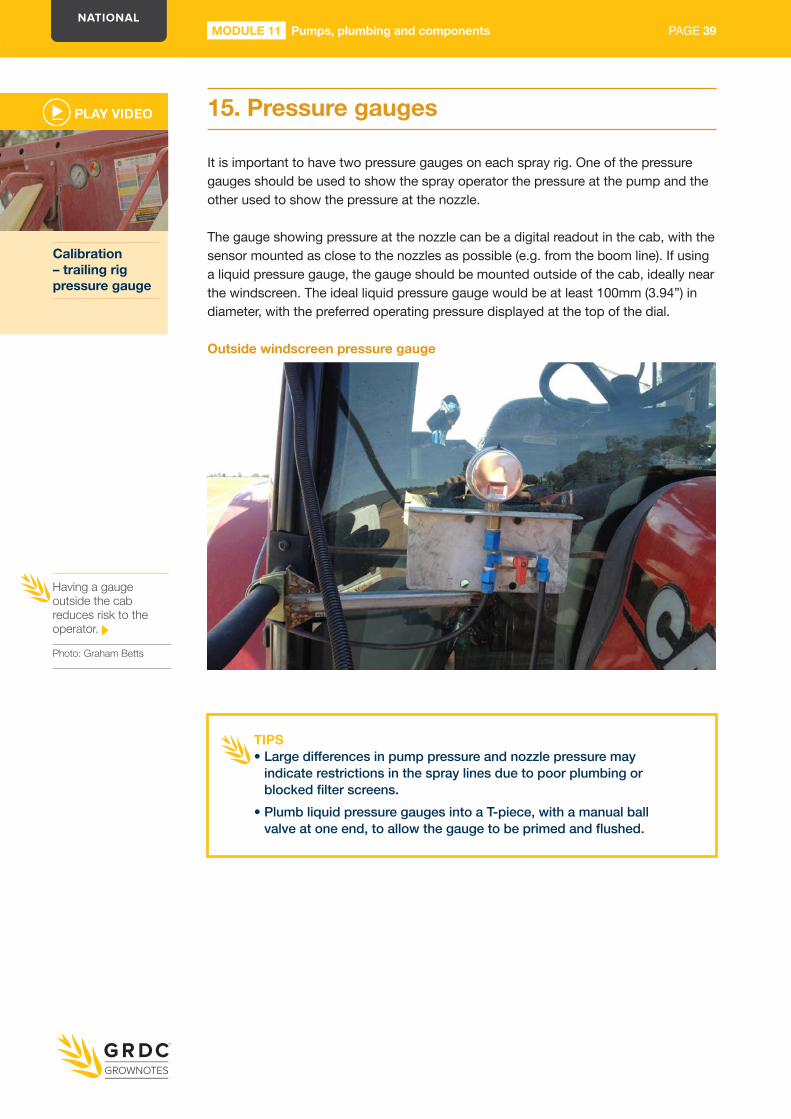
15 Pressure gauges
It is important to have two pressure gauges on each spray rig One of the pressure gauges should be used to show the spray operator the pressure at the pump and the other used to show the pressure at the nozzle
The gauge showing pressure at the nozzle can be a digital readout in the cab with the sensor mounted as close to the nozzles as possible (eg from the boom line) If using a liquid pressure gauge the gauge should be mounted outside of the cab ideally near the windscreen The ideal liquid pressure gauge would be at least 100mm (394rdquo) in diameter with the preferred operating pressure displayed at the top of the dial
Having a gauge outside the cab reduces risk to the operator
Photo Graham Betts
Outside windscreen pressure gauge
Calibration ndash trailing rig pressure gauge
TIPSbull Large differences in pump pressure and nozzle pressure may
indicate restrictions in the spray lines due to poor plumbing or blocked filter screens
bull Plumb liquid pressure gauges into a T-piece with a manual ball valve at one end to allow the gauge to be primed and flushed
PAGE 40MODULE 11 Pumps plumbing and components
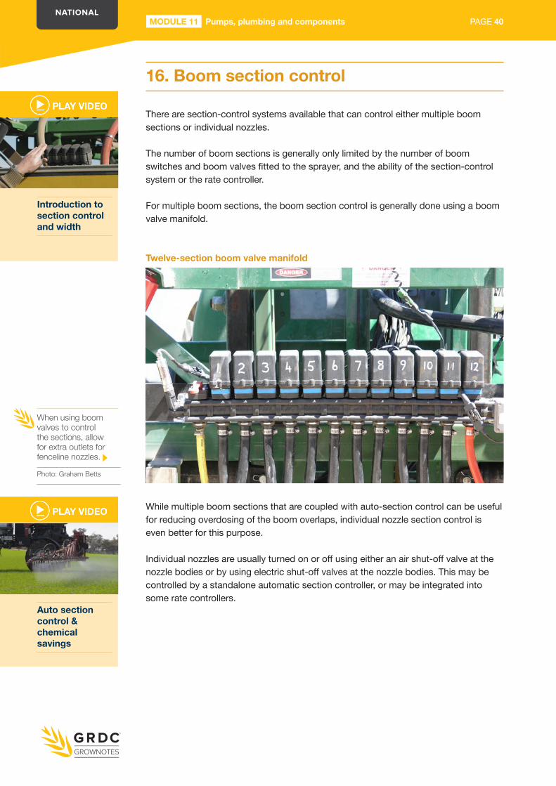
16 Boom section control
There are section-control systems available that can control either multiple boom sections or individual nozzles
The number of boom sections is generally only limited by the number of boom switches and boom valves fitted to the sprayer and the ability of the section-control system or the rate controller
For multiple boom sections the boom section control is generally done using a boom valve manifold
Twelve-section boom valve manifold
While multiple boom sections that are coupled with auto-section control can be useful for reducing overdosing of the boom overlaps individual nozzle section control is even better for this purpose
Individual nozzles are usually turned on or off using either an air shut-off valve at the nozzle bodies or by using electric shut-off valves at the nozzle bodies This may be controlled by a standalone automatic section controller or may be integrated into some rate controllers
When using boom valves to control the sections allow for extra outlets for fenceline nozzles
Photo Graham Betts
Introduction to section control and width
Auto section control amp chemical savings
PAGE 41PAGE 41MODULE 11 Pumps plumbing and components MODULE 11 Pumps plumbing and components
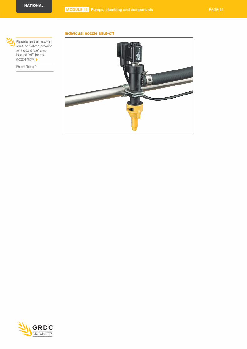
Individualnozzleshut-off
Electric and air nozzle shut-off valves provide an instant lsquoonrsquo and instant lsquooffrsquo for the nozzle flow
Photo TeeJetreg
PAGE 42MODULE 11 Pumps plumbing and components
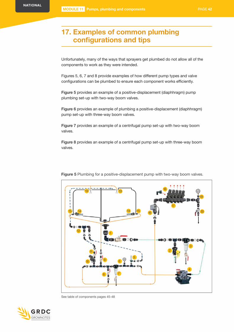
17 Examples of common plumbing configurationsandtips
Unfortunately many of the ways that sprayers get plumbed do not allow all of the components to work as they were intended
Figures 5 6 7 and 8 provide examples of how different pump types and valve configurations can be plumbed to ensure each component works efficiently
Figure 5 provides an example of a positive-displacement (diaphhragm) pump plumbing set-up with two-way boom valves
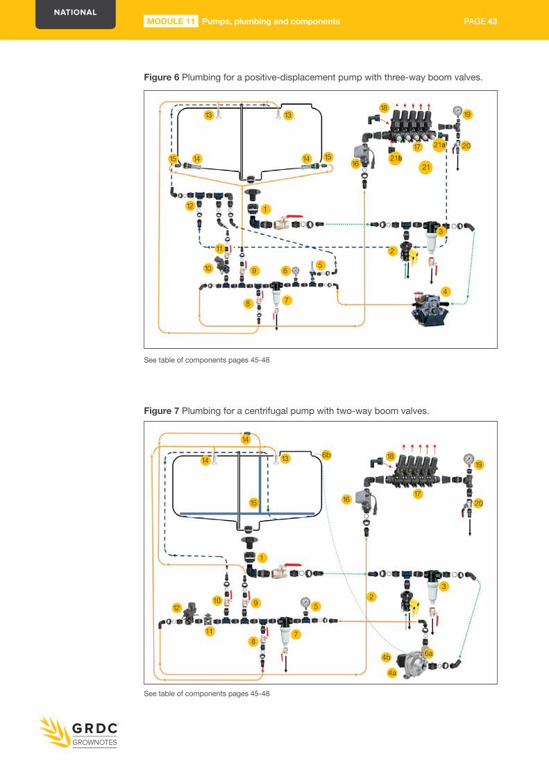
Figure 6 provides an example of plumbing a positive-displacement (diaphhragm) pump set-up with three-way boom valves
Figure 7 provides an example of a centrifugal pump set-up with two-way boom valves
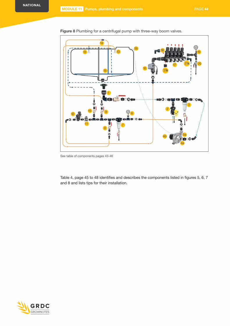
Figure 8 provides an example of a centrifugal pump set-up with three-way boom valves
Figure 5 Plumbing for a positive-displacement pump with two-way boom valves
13 13
15 14 14 15
12 1
9
8 7
65
16
23
4
18
17
19
20
11
10
See table of components pages 45-48
PAGE 43PAGE 43MODULE 11 Pumps plumbing and components MODULE 11 Pumps plumbing and components
Figure 6 Plumbing for a positive-displacement pump with three-way boom valves
Figure 7 Plumbing for a centrifugal pump with two-way boom valves
See table of components pages 45-48
See table of components pages 45-48
14 13
15 16
18
17
19
20
14
12
11
10 9
87
6b
52
3
4a
4b 6a
1
13
14
12
11
10
1
9
8 7
65
1415 1516
18
17 21a
2
3
4
19
20
13
21b21
PAGE 44MODULE 11 Pumps plumbing and components
Table 4 page 45 to 48 identifies and describes the components listed in figures 5 6 7 and 8 and lists tips for their installation
Figure 8 Plumbing for a centrifugal pump with three-way boom valves
13 13
1516
18
17
19
20
14
12
11
10 9
87
5b
62
3
4a
4b 5a
1
21b
21a
See table of components pages 43-46
PAGE 45PAGE 45MODULE 11 Pumps plumbing and components MODULE 11 Pumps plumbing and components
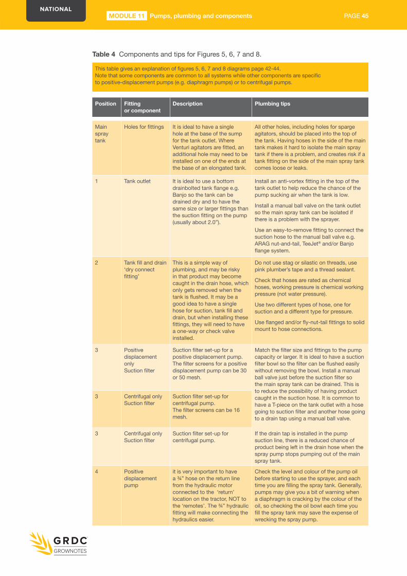
This table gives an explanation of figures 5 6 7 and 8 diagrams page 42-44Note that some components are common to all systems while other components are specific to positive-displacement pumps (eg diaphragm pumps) or to centrifugal pumps
Position Fitting or component
Description Plumbing tips
Main spray tank
Holes for fittings It is ideal to have a single hole at the base of the sump for the tank outlet Where Venturi agitators are fitted an additional hole may need to be installed on one of the ends at the base of an elongated tank
All other holes including holes for sparge agitators should be placed into the top of the tank Having hoses in the side of the main tank makes it hard to isolate the main spray tank if there is a problem and creates risk if a tank fitting on the side of the main spray tank comes loose or leaks
1 Tank outlet It is ideal to use a bottom drainbolted tank flange eg Banjo so the tank can be drained dry and to have the same size or larger fittings than the suction fitting on the pump (usually about 20rdquo)
Install an anti-vortex fitting in the top of the tank outlet to help reduce the chance of the pump sucking air when the tank is low
Install a manual ball valve on the tank outlet so the main spray tank can be isolated if there is a problem with the sprayer
Use an easy-to-remove fitting to connect the suction hose to the manual ball valve eg ARAG nut-and-tail TeeJetreg andor Banjo flange system
2 Tank fill and drain lsquodry connect fittingrsquo
This is a simple way of plumbing and may be risky in that product may become caught in the drain hose which only gets removed when the tank is flushed It may be a good idea to have a single hose for suction tank fill and drain but when installing these fittings they will need to have a one-way or check valve installed
Do not use stag or silastic on threads use pink plumberrsquos tape and a thread sealant
Check that hoses are rated as chemical hoses working pressure is chemical working pressure (not water pressure)
Use two different types of hose one for suction and a different type for pressure
Use flanged andor fly-nut-tail fittings to solid mount to hose connections
3 Positive displacement onlySuction filter
Suction filter set-up for a positive displacement pump The filter screens for a positive displacement pump can be 30 or 50 mesh
Match the filter size and fittings to the pump capacity or larger It is ideal to have a suction filter bowl so the filter can be flushed easily without removing the bowl Install a manual ball valve just before the suction filter so the main spray tank can be drained This is to reduce the possibility of having product caught in the suction hose It is common to have a T-piece on the tank outlet with a hose going to suction filter and another hose going to a drain tap using a manual ball valve
3 Centrifugal onlySuction filter
Suction filter set-up for centrifugal pumpThe filter screens can be 16 mesh
3 Centrifugal onlySuction filter
Suction filter set-up for centrifugal pump
If the drain tap is installed in the pump suction line there is a reduced chance of product being left in the drain hose when the spray pump stops pumping out of the main spray tank
4 Positive displacement pump
it is very important to have a frac34rdquo hose on the return line from the hydraulic motor connected to the lsquoreturnrsquo location on the tractor NOT to the lsquoremotesrsquo The frac34rdquo hydraulic fitting will make connecting the hydraulics easier
Check the level and colour of the pump oil before starting to use the sprayer and each time you are filling the spray tank Generally pumps may give you a bit of warning when a diaphragm is cracking by the colour of the oil so checking the oil bowl each time you fill the spray tank may save the expense of wrecking the spray pump
Table 4 Components and tips for Figures 5 6 7 and 8
PAGE 46MODULE 11 Pumps plumbing and components
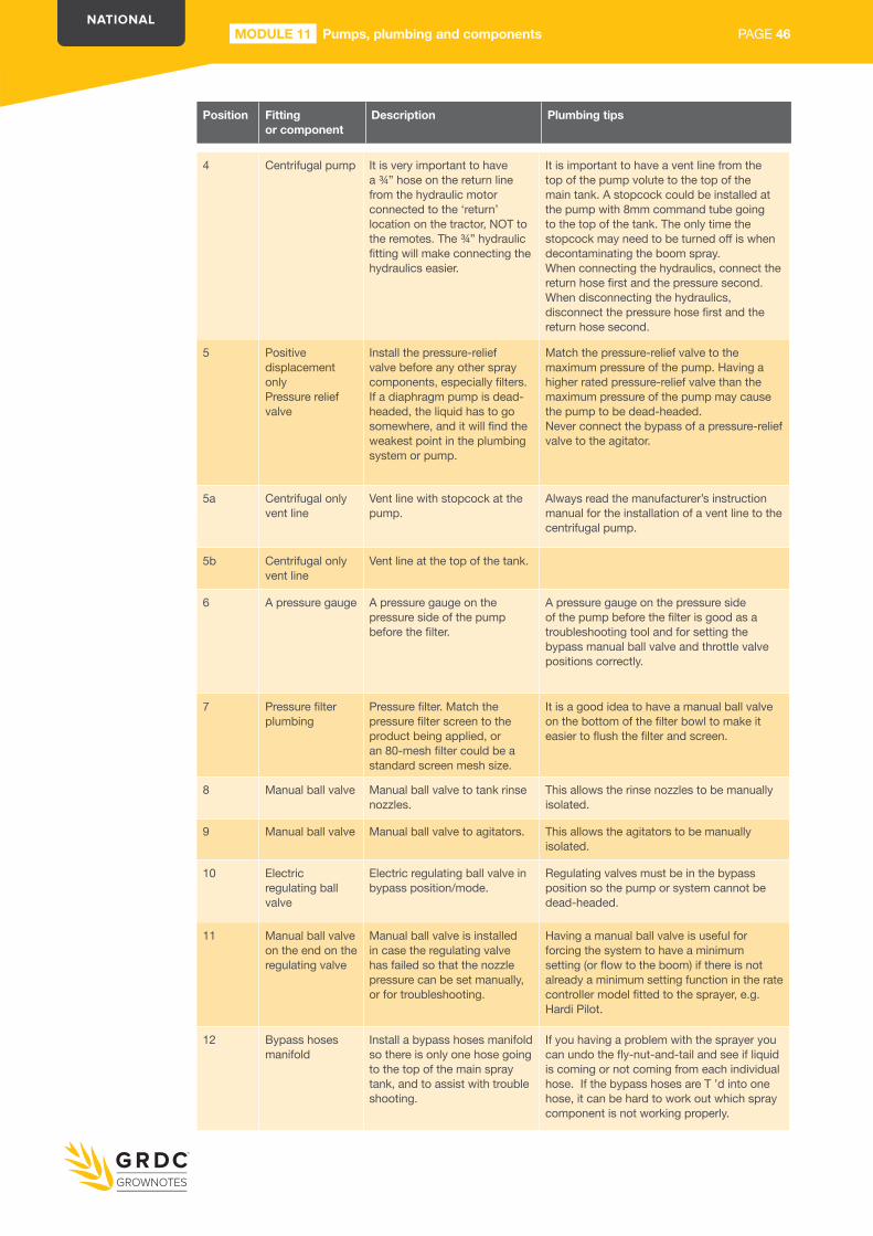
4 Centrifugal pump It is very important to have a frac34rdquo hose on the return line from the hydraulic motor connected to the lsquoreturnrsquo location on the tractor NOT to the remotes The frac34rdquo hydraulic fitting will make connecting the hydraulics easier
It is important to have a vent line from the top of the pump volute to the top of the main tank A stopcock could be installed at the pump with 8mm command tube going to the top of the tank The only time the stopcock may need to be turned off is when decontaminating the boom sprayWhen connecting the hydraulics connect the return hose first and the pressure secondWhen disconnecting the hydraulics disconnect the pressure hose first and the return hose second
5 Positive displacement onlyPressure relief valve
Install the pressure-relief valve before any other spray components especially filters If a diaphragm pump is dead-headed the liquid has to go somewhere and it will find the weakest point in the plumbing system or pump
Match the pressure-relief valve to the maximum pressure of the pump Having a higher rated pressure-relief valve than the maximum pressure of the pump may cause the pump to be dead-headedNever connect the bypass of a pressure-relief valve to the agitator
5a Centrifugal onlyvent line
Vent line with stopcock at the pump
Always read the manufacturerrsquos instruction manual for the installation of a vent line to the centrifugal pump
5b Centrifugal onlyvent line
Vent line at the top of the tank
6 A pressure gauge A pressure gauge on the pressure side of the pump before the filter
A pressure gauge on the pressure side of the pump before the filter is good as a troubleshooting tool and for setting the bypass manual ball valve and throttle valve positions correctly
7 Pressure filter plumbing
Pressure filter Match the pressure filter screen to the product being applied or an 80-mesh filter could be a standard screen mesh size
It is a good idea to have a manual ball valve on the bottom of the filter bowl to make it easier to flush the filter and screen
8 Manual ball valve Manual ball valve to tank rinse nozzles
This allows the rinse nozzles to be manually isolated
9 Manual ball valve Manual ball valve to agitators This allows the agitators to be manually isolated
10 Electric regulating ball valve
Electric regulating ball valve in bypass positionmode
Regulating valves must be in the bypass position so the pump or system cannot be dead-headed
11 Manual ball valve on the end on the regulating valve
Manual ball valve is installed in case the regulating valve has failed so that the nozzle pressure can be set manually or for troubleshooting
Having a manual ball valve is useful for forcing the system to have a minimum setting (or flow to the boom) if there is not already a minimum setting function in the rate controller model fitted to the sprayer eg Hardi Pilot
12 Bypass hoses manifold
Install a bypass hoses manifold so there is only one hose going to the top of the main spray tank and to assist with trouble shooting
If you having a problem with the sprayer you can undo the fly-nut-and-tail and see if liquid is coming or not coming from each individual hose If the bypass hoses are T rsquod into one hose it can be hard to work out which spray component is not working properly
Position Fitting or component
Description Plumbing tips
PAGE 47PAGE 47MODULE 11 Pumps plumbing and components MODULE 11 Pumps plumbing and components
13 Tank rinse nozzles
With rectangular spray tanks it is optimum to have two tank rinse nozzles to have a better distribution for a tank that is narrow one way and long the other way
Use the tank rinse nozzles to reduce the foam in the spray tank during filling and agitation
14 Positive-displacement agitation
Venturi agitators are a good option for positive-displacement pumps but take care to match the agitator(s) to the operating pressure The most common Venturi agitators have a minimum operating pressure of 50 bar If operating at low pressure it may be a good option to use a sparge agitation system
Use two agitators one each side of the tank to improve the swirl of liquid in the spray tankHave a one-way or check valve on the agitator so the spray tank can be isolated when checking plumbing on the sprayerIt is a good idea to have a dedicated agitation pump so agitation is not compromised This is critical for large main spray tanks
14 Centrifugal agitation
When using a centrifugal pump agitation is best done using a sparge agitator A sparge agitator is a piece of tube on the floor of the tank with holes drilled along each side It is best to come in from the top of the tank as per figures 7 and 8
On sprayers with large main tanks it is a good idea to have a dedicated agitation pump so the agitation of the tank mix is not compromised
15 One-way check valves
One-waycheck valves to isolate the spray tank
One-waycheck valves help to prevent contamination
16 Flow meter The flow meter can be attached to the boom valve manifold On the opposite end of the boom valve manifold install a T-piece
Mount the flow meter vertically with a straight length of hose coming into the bottom of the flow meter
17 Two-way boom valve manifold
Modern boom valves have three wires power signal and ground You may need to add a power wire to the wiring harness
Mount the boom valves at the back of the sprayer on the boom centre This will allow you to have one large spray line going from the pressure manifold to the back of the sprayer (instead of many smaller boom line hoses going from the pressure manifold to the back of the sprayer)
18 Boom valve hose tails going to the boom sections
Mount the boom valves on the boom centre at the back of the sprayer
Have boom valves dedicated to fenceline nozzles The fenceline can rob flow and pressure out the boom section if they are plumbed into a boom sectionA boom valve dedicated to a fenceline nozzle can be used as a spare boom valve if one of the other valves fails just swap the hose tail and electric wiringYou may need to use different size hose diameters on various sections to maintain a constant pressure at the nozzle Things that can cause pressure drops are the length of hose to the boom section or the number of (or lack of) nozzles on a boom section
Position Fitting or component
Description Plumbing tips
PAGE 48MODULE 11 Pumps plumbing and components
19 T-piece Install a fitting in the top of the T-piece that is on the end of the boom valve manifold The top of the T-piece is used for gauge electronic pressure sensor or fitting for 8mm airline or command tube The tube goes to a 100mm pressure gauge outside the windscreen
Run at least 100L through the flow meter when performing a flow meter calibration
20 Manual ball valve Install a manual ball valve on the bottom of the T-piece so the boom valve manifold can be flushed
The ball valve will allow the flow meter to be calibrated and help with troubleshooting
21a The bypass manifold
The bypass manifold is part of the three-way boom valve Bypass hose goes to the bypass manifold
Three-way boom valves do not work well with direct injection If using three-way boom valves on a direct-injection system have a manual ball valve on the bypass line
21b Plug for end of bypass manifold
Always plug empty sockets or outlets
Position Fitting or component
Description Plumbing tips
PAGE 49PAGE 49MODULE 11 Pumps plumbing and components MODULE 11 Pumps plumbing and components
19 T-piece Install a fitting in the top of the T-piece that is on the end of the boom valve manifold The top of the T-piece is used for gauge electronic pressure sensor or fitting for 8mm airline or command tube The tube goes to a 100mm pressure gauge outside the windscreen
Run at least 100L through the flow meter when performing a flow meter calibration
20 Manual ball valve Install a manual ball valve on the bottom of the T-piece so the boom valve manifold can be flushed
The ball valve will allow the flow meter to be calibrated and help with troubleshooting
21a The bypass manifold
The bypass manifold is part of the three-way boom valve Bypass hose goes to the bypass manifold
Three-way boom valves do not work well with direct injection If using three-way boom valves on a direct-injection system have a manual ball valve on the bypass line
21b Plug for end of bypass manifold
Always plug empty sockets or outlets
18 General plumbing tips forinstallinghosesandfittings
Always try to reduce all possibile lsquoblind spotsrsquo where product may become trapped never use reducing nipples or T-pieces on the inlet or outlet of a pump
To ensure components are easy to access and maintain consider using some of the following tips
General plumbing tips for the spray operatorFittings
bull It is preferable to have fittings that are easy to remove for installation maintenance and repairs such as Banjoreg GEOLine or ARAGreg fittings
bull Where two fittings need to be screwed into each other use thick (pink) plumberrsquos tape and thread paste to make sealing adjustment and removal easier Do not use silastic-type products or stag Silastic is hard do anything with if there is a leak and fittings that have been put together with stag are very hard to get apart
Hose clampsbull Use good-quality stainless steel hose clamps with a solid band It is a
good idea to spray lubricant onto the hose clamp before trying to adjust them new or old It is easier to tighten a hose clamp if you apply lubricant unscrew the clamp for a bit and then tighten If you try to tighten the hose clamp without doing these steps you may not get the clamp as tight as you need
Hoses bull Make the sprayer plumbing simple as possible always try to reduce the
amount of hose used and reduce or eliminate blind spots
bull The TeeJet Catalogue 51- M (httpwwwteejetcomliterature_pdfscatalogsC51A-Mcat51a_metricpdf) includes useful information on pressure drops through various hose diameters related to the length of hose and the flow rate
bull Hose with crossover webbing is good for going around bends due to its flexibility However it can expand too much when being pressurised or de-pressurised if the pressure rating is not high enough The result of the hose expanding may be that it takes a while for the nozzles to come on (because the hose needs to expand) and the nozzles can take a while to shut off (because the hose needs to contract to original size)
bull Use hose that is the same size or larger than the fittings on the pump
bull Use a hot-air gun to make removing hose from fittings easier and boiling water to install hose on fittings Do not tighten hose clamps before the hose has cooled off
Plumbing ndash section width and potential pressures
PAGE 50MODULE 11 Pumps plumbing and components
Components
bull To make plumbing easier it is best to make up separate manifolds rather than try to put all spray components into a single manifold
bull Use nipple fly-nuts-and-tails eg GEOline and ARAGreg fittings andor flange fittings eg Banjoreg Manifold Systems TeeJetreg DirectoValve Flange Fittings These fittings make it easy to make minor changes to the sprayer when conducting maintenance or repairs to the sprayerrsquos plumbing
bull Install a pressure gauge outside the windscreen of the sprayer or spray tractor that is connected as close to the nozzles as possible Leave the other pressure gauge at the front of the sprayer (on the pressure line from the pump) so the operator knows what the pump pressure is
bull Use filters (suction and pressure) that have a thread on the bottom of the bowl for the installation of a manual ball valve to make flushing easier between dismantling the filter or cleaning the screen
Fenceline nozzle
PAGE 51PAGE 51MODULE 11 Pumps plumbing and components MODULE 11 Pumps plumbing and components
19 Summary
It is important that the spray operator can access all of the components that require regular maintenance or calibration This includes the ability to isolate the main tank from the rest of the spraying system when required
Before purchasing or installing any new component carefully consider what the flow requirements will be for the range of application volumes (Lha) and spraying speeds likely to be done This will help to identify the most appropriate components such as pumps flow meters and valves
This module has tried to provide an overview of how the spraying system can be set up to ensure each of the components works as it is intended to along with many tips to make the installation and operation smoother
For further information on specific components always refer to the literature supplied by the product manufacturers
SPRAY APPLICATION MANUAL FOR GRAIN GROWERS Module 12 GPS systems The options available
NEXT MODULE
PAGE 2MODULE 11 Pumps plumbing and components
Key points
bull The correct plumbing will allow all of the components in the spray system to operate as they are intended
bull Careful consideration must be given to the selection of the pump plumbing valves and other components so they match all of the spray applications the operator plans to make
bull Before the purchase or installation of new components the operator shouldconsiderwhattherangeofflowratesthrougheachcomponentwill need to be
bull The operator should consider how heshe will access maintain and calibrate all of the components on the sprayer before they are installed
bull It is important to consider how various components of the spray system such as the main tank can be isolated from the rest of the spray system to provide safe access for maintenance and inspections
Acronyms used in this module
DIN = Deutsches Institut fuumlr Normung (DIN) the organisation for German national standards
ID = inside dimension
ISO = International Organization for Standardization
OD = outside dimension
PTO = power take-off
RHS = rectangular hollow section
RPM = revolutions per minute
PAGE 3PAGE 3MODULE 11 Pumps plumbing and components MODULE 11 Pumps plumbing and components
1 Introduction
For spraying the principle of using a pump to transfer liquid from the spray tank to the nozzles remains the same as it has for decades but the options available to control the flow to the boom and the output from the nozzles has advanced enormously in recent years
Plumbing has become increasingly important as spray application equipment has increased in size and complexity There are many options available so the operator must ensure that the plumbing and components chosen are suitable for the task and correctly installed to allow the sprayer to perform as intended
There are entire books written about sprayer pumps and components so the aim of this module is not to lsquoreinvent the wheelrsquo but to provide information and tips on how the components can best work together along with how to best install them into the spraying system to ensure it continues to operate efficiently and effectively
The major components of the spraying system and considerations discussed in this module are outlined in Figure 1
Main tank
Flush tank
Filtration
Agitation
Pump(s)
Filtration
Regulation and valves Bypassrelief
Boom and sections Re-circulation
Nozzle bodies
Things for the operator to considerMain tank shape sumps isolationFlush tank size relative to main tankFiltration suction pressure section nozzlesPumps diaphragm centrifugalRegulation pressure relief bypass Agitation sparge venturiValves two way three wayRe-circulation manual or electricNozzle bodies wet boom dry boom
Figure 1 Overview of the major components of the plumbing system
PAGE 4MODULE 11 Pumps plumbing and components
2 The main spray tank
The most common materials that spray tanks are manufactured from are stainless steel polypropylene and fibreglass (with a shiny layer of glass on the inside no fibre showing) Of the three stainless steel tanks will increase the sprayerrsquos weight but will also tend to hold their shape (and known volume) better than the other materials
The most important requirements of the main spray tank are that there are no internal ledges and that it is shaped so it is relatively easy to keep products agitated and in solution The main tank should also have a tapered bottom with a main and secondary sump
Product can become trapped unless it can circulate freely in the tank
Photo Graham Betts
Residue on tank ledges
PAGE 5PAGE 5MODULE 11 Pumps plumbing and components MODULE 11 Pumps plumbing and components
21 Main sump and secondary sump The main sump needs to be in the lowest point of the tank and positioned so that the sprayer frame does not prevent the installation of a tank outlet at the bottom of the sump (not at the side of the sump)
The secondary sump is the shape of the tank floor which should taper from all corners and edges of the tank into the main sump There should only be one hole at the base of the tank (sump) for the outlet An additional hole should only be installed at the end of an elongated tank if Venturi agitation is to be fitted
All other plumbing and return hoses to the tank including the plumbing for sparge agitators should be installed into the top of the tank This will help to reduce potential problems if fittings start to leak and will allow the tank to be isolated from other components This is particularly important if you need to complete work on the plumbing while the tank is full of water or product and to help with troubleshooting or cleaning filter screens
A tank outlet that does not move when installing fittings and allows the tank to totally drain is very practical eg a Banjoreg Bottom Drain manifold bolted tank fitting It is very important to have an anti-vortex fitting in any tank outlet to reduce the chance of the pump sucking air
TIPSbull It is important to use a bottom drain tank outlet eg Banjoreg Poly
Bolted Bottom Drain Tank flanges will allow the tank to be drained completely
bull Install an anti-vortex fitting in the top of the tank outlet to help reduce the chance of the pump sucking air when the tank is low
bull Install a manual ball valve on the tank outlet so the main spray tank can be isolated if there is a problem with the sprayer
bull It is ideal to use lsquoflangersquo or lsquofly-nut-and-tailrsquo fittings to make installation adjustment maintenance servicing and repairs easier For example removing a centrifugal pump to be repaired would be very easy if the pump inlet and outlet fittings are flange or nut-and-tail fittings Ideally these fittings could be used at any location on the sprayer on components that may need to be serviced adjusted or replaced
PAGE 6MODULE 11 Pumps plumbing and components
3Theflushtank
The flush tank should have a capacity that is at least 10 per cent of the capacity of the main tank
It is ideal if the flush tank has its own fill hose from the fresh-water source to reduce the chance of contamination along with a lsquoone-wayrsquo or lsquocheckrsquo valve in the suction line so mixed product cannot move from the main spray tank into the flush tank
Flush tanks are very important for being able to easily flush the pump spray components and nozzles in the field especially if the main spray tank has not been emptied
4 Hand-wash tank
The hand-wash tank (clean water) must be independently plumbed so there is no way it can become contaminated It should have a dedicated fresh water supply fitting that is different to any of the other liquid connections on the sprayer
Carefully consider the volume of water this tank will hold many safety data sheets state that eyes must be flushed with running water for 10 to 15 minutes if product accidently splashes into them It is also ideal to have a soap dispenser next to the hand wash container
PAGE 7PAGE 7MODULE 11 Pumps plumbing and components MODULE 11 Pumps plumbing and components
5 Filtration
Filtration is critical for protecting the sprayerrsquos components and to reduce the potential for nozzle blockages Generally filters are placed before the pump (suction) after the pump (pressure) and before the nozzles (often on boom sections)
There is an ISO standard for the colour of filter screens (related to their mesh size) but unfortunately not all manufacturers use this ISO colour code When ordering a filter it is itherefore mportant to state the mesh size required for the screen not just the colour
Different brands of filter screens are not always the same colour for the same mesh size
Source TeeJetreg
Exampleoffilterscreen
Table 1 The ISO colour code for filter mesh sizes
ISO colour code
Brown red Red Blue Yellow Green Grey (non-ISO)
Orange Pink
Mesh size 16 32 50 80 100 120 150 200
TIPbull Ideally filters should be located where they are easy to access
Locate filter bowls facing downwards and have a manual ball valve on the bowl so the filter is easier to service
PAGE 8MODULE 11 Pumps plumbing and components
51SuctionfiltersThe suction filter is located between the tank outlet and the pump
Suction filters for centrifugal pumps should ideally have a 16-mesh screen or similar which is the most appropriate filter screen size to reduce the chance of any foreign material getting caught in the pumprsquos impeller
Suction filters for diaphragm pumps should ideally have a 30 or 50-mesh screen which are the most appropriate filter screen sizes to protect positive-displacement pumps
52PressurefiltersIdeally the main pressure filter will be installed after the pump but before any of the plumbing components (such as the flow meter and regulating valves)
The main pressure filter should have either 80 or 100-mesh screens which are suitable for both centrifugal and diaphragm pumps It is important to have a pressure-relief valve installed between the pump and main pressure filter when using diaphragm pumps
53Boom-linefiltersBoom-line filters should also have 80 or 100-mesh screens However the mesh size can be changed to suit the nozzle orifice size or formulation type according to the recommendations on the product label
It is best to mount the boom-line filters out on the boom sections They should be plumbed into the spray line at a point as close as practical to where the spray line connects to the boom line
54NozzlefiltersThe mesh size for nozzle filter screens where fitted should match the nozzle orifice size Most nozzle manufacturers will recommend filter sizes to match particular nozzles
Nozzlefilters
Installing boom section filters may be more useful than using nozzle filters
Photo TeeJetreg
PAGE 9PAGE 9MODULE 11 Pumps plumbing and components MODULE 11 Pumps plumbing and components
For most situations it may be preferable that nozzle filters are not installed Generally if there is a problem with products blocking nozzles the source of the problem will be filtration upstream from the nozzles
Nozzle filters can accumulate material on the filter screen due to the low liquid flow rates that occur through a single nozzle At low flow rates the filter screen can strip components out of the formulation (detectable as a film on the screen) This generally does not occur when the same mesh-size screen is used on the boom filters due to the higher flow rates of liquid that will flow to a whole boom section compared to a single nozzle
From the operatorrsquos perspective it may be better to have a blocked nozzle that can be easily seen rather than a nozzle that has restricted the flow due to a partially blocked nozzle filter
TeeJetregfilterbowlwiththreadatbase
TIPSbull The main reasons for having a suction filter on a centrifugal pump are
to protect the pump by taking coarse foreign matter out of the spray solution and to reduce the amount of work the main pressure filter has to do
bull You may need to match the mesh size of the pressure filter screen to the product being used according to information on the product label or to the nozzle orifice size
bull All filters should be mounted so the filter bowl is facing down This way any foreign material falls out when the bowl is removed It is practical to have a manual ball valve at the base of the filter bowl so the filter can be flushed clean without the bowl having to be removed
bull Have a full set of gaskets or O-rings on hand Operators can waste a lot of time trying to install filter bowls with swollen gaskets or O-rings It is useful to place swollen O-rings and gaskets in direct sunlight for several hours (or days) to see if they shrink back to their normal size
Threaded filter bowls allow a ball valve to be installed for flushing the filter
Teejetreg image library
PAGE 10MODULE 11 Pumps plumbing and components
6 Pumps
The most common types of pumps used on sprayers are diaphragm pumps (positive displacement) centrifugal pumps (non-positive displacement) and to a lesser extent roller pumps
Before selecting a pump for the sprayer the operator needs to know what the expected range of flow rates and operating pressures are likely to be After establishing this the operator should carefully examine each pumprsquos performance curve (which shows the pumprsquos flow rate at different pressures) to see which model suits their requirements
Evaluating the performance curve is particularly important when considering purchasing a centrifugal pump or a 12-volt diaphragm pump
The main factors to look at when choosing between diaphragm and centrifugal pumps are the operating pressure required by the nozzles you have chosen to use and the total volume required (eg for the boom and for agitation)
61 Diaphragm pumps Diaphragm pumps are good for maintaining the flow rate (litres per minute) across the entire pressure range the pump is rated for For example the same diaphragm pump can deliver 170Lmin at 20 bar pressure and 165Lmin at 150 bar pressure
Diaphragm pumps are designed to operate at either 540 RPM or 1000 RPM depending on the make and model of the pump and may be PTO-driven or hydraulically driven
Ar150 diaphragm pump
Diaphragm pumps can maintain pressure over their range of flow
Photo TeeJetreg
For more information on howdifferentpump types work go to sprayers101compumps-for-applying-crop-protection-products
Determining pump capacity ndash diaphragm pump example
PAGE 11PAGE 11MODULE 11 Pumps plumbing and components MODULE 11 Pumps plumbing and components
There will be an impact of the RPM on pump performance and output For example the same diaphragm pump at 450 RPM will produce 135Lmin at 500 RPM will produce 150Lmin and at 550 RPM will produce 165Lmin
If using a PTO to drive the diaphragm pump it is important that the draw bar pin is as close as possible to the halfway point between the two yolks If this is not practical you may need to use a wide-angle shaft with the wide-angle-yolk end most commonly fitted to the tractor Alternatively a double bearing block can be installed on the chassis of the sprayer pull
If using a hydraulic drive system for a diaphragm pump it is important to have an aluminium block on the hydraulic motor that will not allow the pump to be run at more than 540 RPM The hydraulic return line for the drive system which should be frac34rdquo must go back to the lsquoreturnrsquo on the tractor hydraulic couplings not the lsquoremotesrsquo
Diaphragm pumps must be fitted with pressure relief valves
Photo TeeJetreg
TeeJetreg 8460 pressure relief valve
611 Diaphragm pumps require a pressure-relief valveIt is essential to install a pressure-relief valve between the pressure outlet of the diaphragm pump and before any other spray components (including the pressure filter) A diaphragm pump must never be dead-headed
The bypass from the pressure-relief valve must be returned back to the main spray tank unrestricted (preferably to the top of the tank) The bypass from the pressure-relief valve and bypass from the regulating valve can both be connected into a common return line to the main spray tank
The bypass from a pressure-relief valve should never be connected to an agitator
TIPbull 540 RPM diaphragm pumps need to run at a minimum of 450 RPM
and a maximum of 540 RPM
PAGE 12MODULE 11 Pumps plumbing and components
A Hyproreg centrifugal pump
62 Centrifugal pumpsCentrifugal pumps are good at delivering larger volumes of flow generally at lower operating pressures (ideally at pressures less than 50 to 60 bar)
Centrifugal pumps are good for delivering high volumes of flow
The performance of a centrifugal pump is highly dependent on the hydraulic oil flow to the pumprsquos motor
For example for a particular brand of centrifugal pump and hydraulic motor combination
bull at an oil flow of 568Lmin the total output is 830Lmin at 28 bar and 72Lmin 76 bar
bull at an oil flow of 606Lmin the total output is 830Lmin at 28 bar and 159Lmin at 83 bar and
bull at an oil flow of 644Lmin the total output is 830Lmin at 28 bar and 220Lmin at 90 bar
TIPSbull Always match the pressure rating of the pressure-relief valve to the
pumprsquos maximum operating pressure For example if the spray pump has a maximum pressure of 80 bar it would not be a good idea to install a 100 bar pressure-relief valve If the pump was not performing correctly it may be tempting to screw the pressure relief T-handle in which may dead-head the pump
bull If you have a TeeJet 8460 model pressure-relief valve it is a good idea to remove the stainless-steel washer from inside the pressure-relief valve to help reduce the pressure spike Remove the four Philliprsquos head screws remove the plunger and diaphragm undo the Philliprsquos head screw from the plunger remove the flat washer and reassemble the pressure-relief valve
PAGE 13PAGE 13MODULE 11 Pumps plumbing and components MODULE 11 Pumps plumbing and components
Match the hydraulic motor to the tractorrsquos hydraulic system capacityThere are commonly five different models of hydraulic motors fitted to centrifugal pumps It is important to match the hydraulic motor for the centrifugal pump to the actual tractor model and its hydraulic system capacity
Always refer to the manufacturerrsquos technical literature for an appropriate pump model to match the hydraulic oil flow available on the tractor or sprayer
63 Agitation systemsThe agitation in the main spray tank must be able to agitate product that may have settled to the bottom of the tank when the pump has been turned off or where the products were not correctly mixed This is particularly important when using powdered or granular formulations
There are two main types of agitation system Venturi and sparge
Venturi agitators are normally used with diaphragm pumps (at high pressure) and sparge agitators are mainly used with centrifugal pumps (at high volume)
Always install a vent line on centrifugal pumps according to the manufacturerrsquos instructions
Photo Graham Betts
Centrifugal pump with vent hose
TIPSbull When using hydraulic-drive centrifugal pumps it is important to read
the instructions particularly the one requiring the installation of a vent line
bull Use frac34rdquo hydraulic hose for the hydraulic return line from the hydraulic motor which must be returned to the dedicated lsquoreturnrsquo fitting in the tractor not lsquoremotesrsquo
bull When connecting all hydraulics for pumps connect the return line first and then the pressure line When disconnecting remove the pressure line first and the return line last
bull The flow from the outlet of the pump should go to the nozzles with the least number of fittings and bends in the hose Make sure that any fittings used are the same size or larger than the outlet size on the pump
bull It is not practical to service spray components if they are solid-mounted on the pump
PAGE 14MODULE 11 Pumps plumbing and components
Venturi agitators require both pressure and flow to perform correctly Most manufacturers of Venturi agitation systems only provide performance information for operating pressures above 50 bar
Sparge agitation systems are relatively simple comprising a tube running the length of the tank with a series of holes in either side of it to direct liquid downwards and to the sides of the tank The sparge tube is normally placed quite low in the tank to ensure the liquid flow is able to move product that may have settled However to be able to do this a high volume of liquid must flow through the sparge tube
Sparge agitation tube in the base of a Rogatorreg tank
Ideally spargreg agitator tubes would be fed from the top of the tank
Photo Graham Betts
Venturi agitators typically require higher pressures to engage and operate effectively
Photo Graham Betts
Venturi agitators in a John Deere sprayer
PAGE 15PAGE 15MODULE 11 Pumps plumbing and components MODULE 11 Pumps plumbing and components
64 Determining required pump capacity (forboomflowandagitation)
To determine the pump and plumbing capacity required for the sprayer the operator must consider the range of flow rates that are likely to be required by the boom as well as the additional capacity required to run the agitation system efficiently
Working out the pump capacity required for a sprayer Hypro Pumps recommends that
ldquoThe flow required from the pump should be the total of the flow required for the boom plus the flow required for agitation plus another 20 for a bufferrdquo
As a guide agitation requirements for different products in the tank mix are as follows
bull for liquid products the agitation requirement is the tank volume x 005 in litres per minute and
bull for powders or lsquoflowablesrsquo the agitation requirement is tank volume x 0125 in litres per minute
(Source Hypro Pumps Spray Tips and Accessories Catalogue 2012)
It may be useful to complete the following exercise to determine the required pump capacity and to also consider the pressures required to operate the nozzles and agitation system effectively
The following example considers the flow rates required to match the boom width and application rates (Lha) at a range of spraying speeds
TIPSbull It is ideal to have a dedicated agitation pump especially with the
larger main spray tanks that many modern sprayers havebull If you are using the spray pump for product transfer and spraying
it is important to have two separate pressure-regulation systems One system for spraying and agitation eg a pressure-relief valve set at 60 bar and the second system set at 100 bar for transfer If using only one regulation system (for boom agitation and filling) which has been set to around 100 bar for transfer the performance of the sprayer could be compromised because the regulating valve could be in the wrong position which will greatly affect the sprayerrsquos ability to adjust the application rate in response to changes in speed or section control
PAGE 16MODULE 11 Pumps plumbing and components
Table 2 Calculations of total flow through the boom required for the above example
Using the above calculations the operator can determine that for this example heshe will require a pump and plumbing system that can handle flow rates down to 204Lmin for the main hoses and fittings and flow rates down to 29Lmin for the boom section components and fittings (204Lmin divide 7 sections)
From the same example the operator can also determine that heshe will require a pump and plumbing system that can handle flow rates up to 1021Lmin for the main hoses and fittings and flow rates up to 146Lmin for each of the boom section components and fittings (1021Lmin divide 7 boom sections)
Agitation requirementsFrom the previous example using a 4000L main spray tank the spray pump needs to be able to deliver
bull 102Lmin to the nozzles at the optimum pressure that the nozzles need to be operated at
bull 200Lmin for agitation of liquid formulations (tank volume x 005 = agitation volume (Lmin)) and
bull 500Lmin for agitation of powdered formulations (tank volume x 0125 = agitation volume (Lmin))
Fromtheaboveexamplethetotalflowrequiredfromthepumpwhenapplyingliquidsat100Lhaand25kmhis102Lmin(fortheboom)+200Lmin(foragitation)+20(buffer)=3624Lmincapacity(attherequiredoperatingpressure)
It may be possible to use a Venturi agitator to achieve the above requirements but it would be important to check the pressure or flow requirements and ratings for the particular brand of Venturi agitator you may be considering as some models require a minimum of 50 bar pressure to start the agitator
Boom width X Lha x kmh divide 600 =
Total litres per minute
245 X 50 x 10 divide 600 = 204
245 X 50 x 20 divide 600 = 408
245 X 50 x 25 divide 600 = 510
245 X 75 x 10 divide 600 = 306
245 X 75 x 20 divide 600 = 612
245 X 75 x 25 divide 600 = 766
245 X 100 x 10 divide 600 = 408
245 X 100 x 20 divide 600 = 816
245 X 100 x 25 divide 600 = 1021
Tip If section widths are not even work out the proportionofflowto each section to determine the most appropriate capacity for valves components and fittings
Example Flow requirements for a 24m sprayer with a 4000L tank plumbed in seven sections (of equal length) at three common application volumes and three spraying speeds
PAGE 17PAGE 17MODULE 11 Pumps plumbing and components MODULE 11 Pumps plumbing and components
7 Regulating valves
The purpose of regulating valves is to ensure the required volume of liquid is delivered to the boom or boom sections in response to changes in spraying speed or section control operating To do this the liquid flow must either be restricted (throttle mode) or diverted back to the tank (bypass mode)
Operators should be aware that each sprayer manufacturer may use several different types of regulating valves on their particular brand of sprayer which they may change between models or over time
Common types of regulating valves include ball valves plunger valves and butterfly valves
The shape of the orifice in the regulating valve can be important to how it functions The standard ball (R-type valve) provides the least sensitive regulation whereas other variations on the orifice shape allow for more sensitive regulation of flow
Figure 2 Ball regulating valves
Regulating valves can work more efficiently when used in conjunction with three way boom valves
Photo TeeJetreg
TeeJet RL-type ball lsquospecial shaped ballrsquo RL balve
TeeJet PR-type ball lsquovee shaped ballrsquo PR valve
TeeJet R type ball lsquostandard ballrsquo R-type valve
Source Teejetreg catalogue 51-m
TeeJetreg regulating valve
PAGE 18MODULE 11 Pumps plumbing and components
71InstallingregulatingvalvesfordifferentpumpsandusesFor diaphragm pumps install regulating valves in bypass mode The regulating valve should be plumbed to the side of the pressure line before the flow meter with the bypass flow going back to the top of the tank (see figures 5 and 6 pages 42 and 43 for examples of how regulating valves may be plumbed for diaphragm pumps)
For centrifugal pumps install regulating valves in throttle mode
The regulating valve should be plumbed into the pressure line that is going to the boom valves (see figures 7 and 8 pages 43 and 44 for examples of how centrifugal pumps and valves may be plumbed)
The only exception to using throttle mode on a centrifugal pump may be when trying to control low liquid flow rates (eg liquid systems on seeders or planters) For low flow rates with a centrifugal pump it is a good idea to install the regulating valve in bypass mode with the additional flow going back to the top of the tank
Most self-propelled sprayers do not have a regulating valve in the liquid system they regulate the liquid flow to the boom by adjusting the hydraulic oil flow to the hydraulic motor on the spray pump
ARAG stainless shaped ball Source TeeJetreg technologies catalogue 51-M
ARAG proportional regulating valve
Source Teejetreg
For more information on setting regulating valves go to Module 6 Pre-operational and regular checks
TIPSbull For liquid systems that use regulating valves always check the
pressure rating of the valve and that the regulating mechanism suits your application
bull It is very important to set the position of the lsquobutterflyrsquo or lsquoballrsquo within the regulating valve correctly to get the best out of the sprayer Performing a pre-field check using the simulated speed function is very important for checking that the valve settings are appropriate
bull Avoid using one regulating valve for both filling operations and controlling the sprayer output A good solution is to two separate systems one for spraying and agitation and another one for chemical transfer Switching between the two systems can be achieved by using continuous flow three-way ball valves to avoid dead-heading either system
PAGE 19PAGE 19MODULE 11 Pumps plumbing and components MODULE 11 Pumps plumbing and components
8 Flow meters
There are two types of flow meters commonly used on sprayers impeller flow meters and electromagnetic flow meters
Impellerflowmeterscomeinarangeofsizesandflowcapacities
81ImpellerflowmetersImpeller flow meters have traditionally been the most common flow meters used on sprayers
As the name suggests they use an impeller located in the meter housing which is mounted on a shaft As liquid passes over the impeller it rotates and signals or pulses (based on the number of revolutions) are sent to the rate controller to indicate the flow rate of the liquid
Impeller flow meters will have a calibration factor or figure that may need to be changed to take into account possible changes in the density or viscosity of the product being used
To maintain their accuracy impeller-type flow meters need to be serviced regularly by cleaning the impeller and removing any build-up of product and checking for possible wear of the bearings
Always check the minimium flow requirements for the flow meter match what the sprayer may actually require
Photo TeeJetreg
For more information on calibrating flowmetersgo to Module 8 Calibration of the spray system
PAGE 20MODULE 11 Pumps plumbing and components
82ElectromagneticflowmetersElectromagnetic flow meters rely on a pulse and have no moving parts They are less likely to be impacted by the density or viscosity of the spray solution They are becoming more common on sprayers as operators increase the use of liquid fertilisers and other spray solutions with higher densities
For the best results when using an electromagnetic flow meter they should be mounted into the spray line so that the flow meter is orientated vertically (flow coming in the bottom and out the top) ensuring that the sensor is facing sideways (sending pulses horizontally through the liquid)
Mounting the flow meter this way reduces the likelihood that air or turbulence in the spray line will impact on the accuracy of the reading
ARAGelectromagneticflowmetermountedvertically
Vertical mounting of flow meters improves accuracy and reduces potential blockages
Photo Graham Betts
Plumbing ndash Mounting of flowmeters
PAGE 21PAGE 21MODULE 11 Pumps plumbing and components MODULE 11 Pumps plumbing and components
83ConsiderthelowerlimitofflowthateachflowmetercandetectMost flow meters will have a lower limit of flow that they can detect which the meter manufacturer will state in the product literature
If the flow rate through the flow meter drops below the minimum that it can detect it will not be able to provide information to the rate controller to correctly adjust the sprayerrsquos output
Low flow rates through a flow meter can create a problem for many spray applicators especially when the sprayer is fitted with narrow boom sections or when using an individual nozzle shut-off system where the flow rates can be particularly low at low spraying speeds
Where individual nozzle shut-off or narrow section widths are used it may be important for the sprayer to be fitted with a rate controller that can utilise bothflowand pressure readings to enable it to adjust the sprayerrsquos output
For example when the flow through the flow meter drops below the minimum that the flow meter can detect the rate controller is able to switch to using the nozzle pressure to adjust the sprayerrsquos output When the flow rate through the flow meter comes back into its operational range the rate controller reverts back to using the measured flow to adjust the sprayerrsquos output
For more information on preparing spray plans go to Module 5 Spray plans
TIPSbull Always recalibrate the flow meter after it has been servicedbull Ideally impeller and electromagnetic flow meters should be mounted
vertically with the outlet at the top and the feed from the bottom using a length of straight hose (about 10 times the size of the flow meter inlet) This will reduce the possibility of air affecting the flow reading Mounting the flow meter vertically reduces the chance of product settling in the flow meter
bull It is ideal to have a manual ball valve positioned somewhere past the flow meter (eg on the end of boom valve manifold) to make it easy to flush the manifold and to make it easy to calibrate the flow meter
bull Mount electromagnetic flow meters so the sensor is facing horizontally bull It may be useful for the operator to complete spray plans to work out
the required flow range of the flow meter
PAGE 22MODULE 11 Pumps plumbing and components
9 Boom valves
There are three different types of boom valves that are commonly fitted to sprayers solenoids ball valves and plunger valves
91 Solenoid boom valves with diaphragms Solenoid boom valves with diaphragms are a common boom valve used on sprayers with narrow booms and are also used to control the nozzle output on the WeedSeekerreg (target-selectable sprayer)
Examples include TeeJetreg DirectoValvereg Goyen solenoid valves and Texas Industrial solenoid valves
Most solenoid boom valves generally operate based on a lsquotwo-wire systemrsquo comprising a lsquosignal wirersquo and a lsquoground wirersquo which allows the liquid flow to turn on and off very rapidly
Some possible limitations of solenoid valves are
bull they must have power to remain open which can generate heat in the solenoid
bull they may continue to draw current from the battery if the boom switches are left on and
bull the solenoidrsquos diaphragm may be affected by the formulation type of the products used which can limit the flow rate
92 Ball boom valvesBall boom valves are commonly supplied with either nylon balls or stainless steel balls Examples include TeeJetreg DirectoValve and Banjo electric valves
Ball boom valves only need power to open or close the valve so there is no need for constant power when the valve is off (they will not flatten the battery if the controller panel is left on)
Generally ball boom valves require a lsquothree-wire systemrsquo comprising lsquopowerrsquo lsquogroundrsquo and lsquosignalrsquo wires More recent wiring looms tend to have three wires to each of the boom valves
Some older wiring looms (eg lsquotwo wirersquo) may require the installation of a dedicated lsquopower wirersquo to be able to operate ball boom valves
TIPbull It is important to match the material that the ball is made of to the
product being used eg stainless-steel balls for liquid fertilisers
PAGE 23PAGE 23MODULE 11 Pumps plumbing and components MODULE 11 Pumps plumbing and components
93 Plunger boom valves Plunger boom valves are very common on many spraying systems due to their speed of operation and the accuracy of regulation that can be achieved with some models
Examples of plunger boom valves include Hardi boom section valves GEOlinereg electric section valves and the ARAG Electrovalve
94 Two-way boom valves Two-way valves are the most common boom valve fitted onto sprayers
With a two-way boom valve the flow simply comes into the boom valve and can only go out to the boom (or section) When using two-way boom valves with a manual control system the pressure in the boom may spike when a boom switch or section is turned off When using an automatic rate controller with two-way boom valves the pressure may spike briefly when a boom switch (or section) is turned off However the pressure will return to normal once the regulating valve can adjust the flow to match the new overall width
95 Three-way boom valvesUnlike two-way valves where flow coming into the boom valve can only go out to the boom (or section) with a three-way valve installed when a boom switch is turned off the flow from the valve goes to a return line back to the top of the tank
When using three-way boom valves with a manual system the pressure will remain the same when a boom switch is turned off provided the correct adjustments have been made to the manual return valve
A TeeJetreg 2-way boom manifold
With a two-way manifold flow can only go from the manifold to the boom section
Photo TeeJetreg
PAGE 24MODULE 11 Pumps plumbing and components
When using an automatic spray rate controller with a three-way boom valve the pressure will remain the same when a boom switch (or section) is turned off As a result the regulating valve does not have to make any adjustments to the flow
Installing three-way boom valves is a good option for most sprayers provided the controller is able to operate them However they may not be directly compatible with chemical injection systems
Three-way boom valves are very good when using small boom sections or for systems that have individual nozzle shut-off because the flow meter does not have to work at the minimum flow it is capable of reading
When using three-way boom valves the flow meter reads the total flow but the controller lsquoknowsrsquo to work out the litres per hectare based on the boom sections or nozzles that are actually turned on
By setting up the spray system with three-way boom valves the workload on the regulating valve is reduced as it only has to respond when there is a speed adjustment
96 Flow-back boom valves Flow-back boom valves are located on the boom itself When a boom section is turned off by closing the boom valve (eg a two-way boom valve) the flow-back boom valves open to release the pressure from the boom line returning the liquid flow back to the top of the tank This type of boom valve allows the non-drip check valves on the nozzles to shut off the spray very quickly
With a three-way boom manifold flow can be returned to the tank when a boom section is switched off The amount of flow returned to the tank is able to be adjusted with some models
Photo TeeJetreg
A TeeJetreg 3-way boom manifold
TIPSbull Always have a can of contact cleaner on hand for servicing
connections and to troubleshoot electrical faults bull Most boom valve manufacturers use DIN connectors on their boom
valves which makes them easy to install service and to maintain the electrical connections
PAGE 25PAGE 25MODULE 11 Pumps plumbing and components MODULE 11 Pumps plumbing and components
10 Nozzle bodies and mounting
There are two common ways that nozzle bodies can be mounted as a dry boom mount or a wet boom mount
Wet boom nozzle bodies are clamped onto a tube (the spray line) and dry boom bodies are connected by hose
101 Wet boom plumbingWet boom mounting tends to be the prefered way of mounting nozzle bodies on modern sprayers as this provides for fewer restrictions in the spray line and spray lines are generally easier to decontaminate than with dry boom fittings
When mounting a wet boom nozzle body to a tube make sure that both the OD of the tube and ID of the nozzle body clamp are accurately measured
Wet boom nozzle bodies can be supplied to match metric and imperial OD tube Always check the size of the hole that is required in the tube to match the nipple in the wet boom nozzle body (eg 10 or 7 millimetres)
A wet boom nozzle body
Plumbing ndash matching nozzle spacing boom recirculation and single nozzle section control
Wet boom nozzle bodies are clamped over holes in the boom line Always check the required hole size for the brand and model selected
Photo TeeJetreg
PAGE 26MODULE 11 Pumps plumbing and components
102 Dry boom plumbing Dry boom nozzle bodies can be mounted onto round pipe or RHS steel using nozzle body clamps (see examples below)
Hardi wet boom stainless-steel plumbing
Always select dry boom nozzle bodies with the largest hose barbs available
When connecting the dry boom nozzle bodies with a hose always select an appropriate hose type that is rated for use with agricultural chemicals
Wet boom plumbing reduces the opportunity for residues to build up in the spray lines
Photo Graham Betts
Choose dry boom nozzle bodies with the largest hose barbs available
Photo TeeJetreg
A dry boom nozzle body
PAGE 27PAGE 27MODULE 11 Pumps plumbing and components MODULE 11 Pumps plumbing and components
Dry boom plumbing
Dry boom plumbing introduces more restrictions to flow and places where product may become trapped in the spray lines
Photo Graham Betts
Source TeeJetreg Technologies Catalog 51-M
Figure 3 Examples of dry boom clamps to hold nozzle bodies
QJ111 QJ111SQ AA111 AA111SQ
Go to wwwteejetcomliterature_pdfscatalogsC51A-Mcat51a_metricpdf
TIPbull Try to avoid dry boom plumbing sections that are too long for
the hose diameter as pressure drops will occur across the boom Consult a table that shows the pressure drop through various lengths of hose of different diameters such as in the TeeJet Catalogue 51A-M
PAGE 28MODULE 11 Pumps plumbing and components
11 Non-drip check valves
Always check the pressure rating of non-drip check valves before purchase or installation
One of the causes of nozzle bodies that are slow to shut off or that continue to drip after the boom section has been turned off could be the pressure rating of the non-drip check valve Some non-drip check valves are rated to open at pressures as low as 075 bar
It is very useful to have the highest pressure rated non-drip check valve that will match the nozzle types being used and the minimum setting on the rate controller (eg a 20 bar rating for use with low-pressure air-induction nozzles)
An alternative to the check valve is to use either an electric nozzle shut-off or an air nozzle shut-off system Both electric and air shut-off systems provide positive shut-off and turn-on for the nozzles
Always check the pressure rating that the non-drip valves will open and close at
Photo TeeJetreg
A TeeJetreg non-drip check valve
PAGE 29PAGE 29MODULE 11 Pumps plumbing and components MODULE 11 Pumps plumbing and components
12 Number of outlets on the nozzle body
Operators will generally be offered a choice by the sprayer manufacturer regarding the number of nozzle outlets they require per nozzle body Nozzle bodies are commonly available with one two three four or five outlets
There are strengths and limitations to using multiple-outlet nozzle bodies One of the greatest benefits of having multiple nozzles fitted on the one nozzle body is the ability to easily change the nozzle type or orifice size to match the product or tank mix the conditions and the operating parameters
One of the possible limitations to using multiple-outlet nozzle bodies is that they can become contaminated dirty or blocked if the lsquoturn-overrsquo or lsquorotationrsquo ability is not used regularly or the outlets are not covered by a nozzle and cap or a blanking cap during spraying operations
When rotating nozzle bodies become hard to turn they need to be pulled apart washed in hot soapy water and re-installed using an appropriate lubricant
Multiple nozzle bodies are very useful but require maintenance
Photo Bill Gordon
Five-nozzle body
TIPSbull Nozzle manufacturers make manual shut-off check valve assemblies
which may be useful for turning a selection of nozzles on and off For example manually shutting off half the nozzles when alternating between narrow nozzle spacings and wide nozzle spacings (eg going from 025m spacing for fungicide applications to 05m for fallow spraying)
bull If the nipple is broken in the wet boom body find some tube of the same size drill out the broken nipple and glue the new piece of tube into the nozzle body
PAGE 30MODULE 11 Pumps plumbing and components
13 Boom re-circulation
The main reason to consider boom re-circulation is the ability to prime the boom line with the tank mix before having to turn the nozzles on This eliminates the need to flush the tank mix through the boom line in the paddock
Boom re-circulation is also very useful to reduce the likelihood of products settling out in the boom line when the nozzles or boom sections are turned off as the spray solution in the boom lines can be returned back to the tank
A possible drawback to having a boom re-circulation system is the possibility that diluted product may be returned back to the main spray tank which makes most re-circulation systems incompatible with direct-injection systems
131 Setting up boom re-circulationThe general idea for a re-circulation system is to have a return line from the end of each of the boom sections that takes liquid back to the top of the tank This will keep the tank mix products circulating when the nozzles are turned off
Normally this can be achieved by having a common return line that runs along the boom to the top of the tank where each of the boom section return lines are plumbed into using T-pieces
Using re-circulation requires that the nozzles are able to be shut off to prevent flow coming out of the nozzles while the re-circulation is engaged
There are a range of air shut-off nozzle bodies and electric shut-off nozzle bodies that can turn off the nozzles while allowing liquid to flow through the boom section
Re-circulation allows booms to be primed before turning the nozzles on
Photo Graham Betts
Manual boom re-circulation
Benefitsofboom re-circulation
PAGE 31PAGE 31MODULE 11 Pumps plumbing and components MODULE 11 Pumps plumbing and components
An alternative system to allow flow to return to the tank while the nozzles are shut off is to fit non-drip check valves that only open at higher pressures (eg rated to open at a minimum pressure of 20 bar) this way liquid can be re-circulated at lower pressures (10 to 15 bar) without the nozzles opening
To be able to control the lsquoengagementrsquo or lsquodisengagementrsquo of the re-circulation system requires that a valve be installed between the end of each boom section and that the flow from the section is fed into a common return line to the tank when the valve is opened
It is also useful to have an additional valve at the end of the common return line just before the return line enters the tank This allows the common return line to be isolated if repairs or decontamination are required As with other plumbing on the sprayer it is important to use fly-nut-and-tail fittings to make access servicing and maintenance easier
There are three options for setting up a boom re-circulation system the only difference between the three options is the types of valves that may be used (see Figure 4)
Check the current draw for electric nozzle shutoff valves before installation particularly for wide booms
Photo Teejetreg
Electricnozzleshut-offvalve
PAGE 32MODULE 11 Pumps plumbing and components
Positioninthediagramabovecomponentorfittingtypeandplumbingtips
Position Fitting or component Description Plumbing tips
a Boom valves Boom valve manifold
b Pressure hose From boom valve one to boom section one
Plumb the flow into each boom section into one end of the boom section not into the centre of the boom section
c From boom valve two to boom section two
d From boom valve three to boom section three
e Ball valve Flush tap on the end of boom section one
Use ball valves on the opposite end of each boom section to the liquid feed these can act as a flush tap
f Flush tap on the end of boom section two
g Flush tap on the end of boom section three
h Return hose Boom 3 return line Use a minimum of 1rdquo hose as the return line Use fly-nut-and-tail fittings to make servicing easier T boom section two flush tap into the return line from boom section one
i Boom 2 return line
j Boom 1 return line
k Return line back to the top of the main spray tank
j
e f
ib
a
c d h
g
k
Figure 4 An example of how boom re-circulation can be plumbed
Table 3 Components and tips for installing a re-circulation system
PAGE 33PAGE 33MODULE 11 Pumps plumbing and components MODULE 11 Pumps plumbing and components
132 Options for setting up a re-circulation systemThe basic option ndash manual ball valves
Establish a common return line that runs along the booms and back to the top of the tank
Install manual ball valves (with a lsquobutterfly handlersquo) at one end of each boom section (opposite end to the feed)
A basic version of boom re-circulation using manual valves is easy to install
Photo Graham Betts
Photo Graham Betts
Manual return line into the top of the tank
End of boom manual boom re-circulation
PAGE 34MODULE 11 Pumps plumbing and components
Attach a return line for each section into the common return line This should run from the manual ball valve to a T-piece installed into the common return line
Between the common return line and the top of the tank install another manual ball valve close to the tank
Electric valves make it easier for the operator to engage and disengage the re-circulation system
Photo Graham Betts
Photo Graham Betts
Along the boom manual boom re-circulation
Manual return line into the top of the tank
The basic electric option Set up the plumbing as in lsquobasic optionrsquo with manual ball valves at the end of each boom section
Replace the manual ball valve at the top of the tank with an electric ball valve (at the end of the return line)
PAGE 35PAGE 35MODULE 11 Pumps plumbing and components MODULE 11 Pumps plumbing and components
Electric valves make it easier for the operator to engage and disengage the re-circulation system
Photo Graham Betts
Electric valves allow the re-circulation to be engaged or disengaged from the sprayer cab
Photo Graham Betts
Along the boom electric boom re-circulation
End of boom electric boom re-circulation
The best optionSet up all the plumbing as in lsquobasic electric optionrsquo with electric ball valves at the end of each boom section and an electric ball valve on the return line at the top of the tank
PAGE 36MODULE 11 Pumps plumbing and components
133Re-circulationballvalvepositionsfordifferentpurposes Ball valve positions when priming the boom Turn the ball valves located at the end of the boom sections and at the top of the tank to the lsquoopenrsquo position then with the pump operating turn each of the boom sections switches in the controller to the lsquoonrsquo position
If the sprayer has non-drip check valves on the nozzle bodies to prevent flow (eg rated to open at 20 bar) ensure there is only 10 to 15 bar pressure in the spray line to ensure the nozzles do not start to spray
Ball valve positions when sprayingJust prior to spraying after the boom is primed unfolded and turn the boom sections to switch off position at the controller (to stop the re-circulation)
Turn the ball valves at the end of the boom sections to the lsquoclosedrsquo position This will cause the spray solution to come out of the nozzles once the switches to the boom sections on the controller are turned on again
BallvalvepositionswhenflushingthesystemIf the tank is empty at the end of a spray job clean water from the flush tank may be used to flush the re-circulation system however this will send some diluted product back to the tank
Turn the re-circulation valves at the top of the tank and at the end of each boom section to the lsquoopenrsquo position (Check the system pressure if using non-drip check valves to stop flow from the nozzles)
Turn the boom section switches in the controller lsquoonrsquo and flow will now return to the tank
Click to go to the Hypro website legacyhypro pumpscomen-usToolsSelectionGuide
PAGE 37PAGE 37MODULE 11 Pumps plumbing and components MODULE 11 Pumps plumbing and components
Disconnecting return lines for decontamination After adding an appropriate decontamination agent to the tank use the re-circulation system while agitating the tank Allow the cleaning products to stay in the tank and re-circulation system for an appropriate amount of time then drain the tank and rinse with clean water
After rinsing and draining the tank avoid any product remaining in the re-circulation system returning to the tank Disconnect each of the boom section return lines from the valves at the end of each boom sections to allow for an open flow (this may be done by removing fly-nut-and-tail) Engage each boom section switch on the controller one at a time to maximise flow through each section of the boom
Once the boom sections have been flushed with clean water reconnect the return lines to the valves at the end of the boom sections and disconnect the common return line from the ball valve at the top of the tank then flush clean water through the common return line
The decontamination agents and number of flushes should follow the procedures outlined in Module 7 lsquoMixing and decontamination requirementsrsquo
For more information go to Module 7 Mixing and decontamination requirements
PAGE 38MODULE 11 Pumps plumbing and components
14 Hydraulics for the pump and plumbing system
Hydraulic drive is the best way to drive a diaphragm pump as there are generally too many issues with using PTO-driven shafts particularly for the safety of the operator
Diaphragm pumps (540 RPM models) that are hydraulically driven need to be set up so they cannot be run below a minimum of 450 RPM or above a maximum of 540 RPM Operators should install a fitting on the hydraulic drive block so that the pump cannot be run over 540 RPM no matter what the hydraulic setting or oil pressure is
Centrifugal pumps may not be able to perform as intended if the hydraulic plumbing is not correctly set up or adjusted Hydraulic motors on hydraulic centrifugal spray pumps need to be matched to the hydraulic capacity and system of the tractor
Always check the pump manufacturerrsquos website for the most appropriate model of hydraulic motor to match the tractor model or hydraulic oil flow capacity of the sprayer
When establishing the hydraulic plumbing to and from the hydraulic motor on the spray pump it is very important to have a frac34rdquo hydraulic hose going back to the dedicated lsquomotor return RETrsquo fitting on the tractor not the lsquocase drain TANKrsquo
Plumbing the hydraulics correctly can reduce the back pressure which needs to be no greater than about 50 psi This will help to reduce heat build-up and will extend the life of the seals in the hydraulic motor
While it is not common practice some centrifugal pumps can be operated at pressures of up to 100 or 120 bar provided the hydraulic plumbing is correctly selected and installed
Go to Hypro website httplegacyhypropumpscomen-usToolsSelectionGuide
TIPbull When connecting the hydraulics always connect the return
hose first and the pressure hose last and do the opposite when disconnecting the hydraulics remove the pressure hose first and the return hose last
PAGE 39PAGE 39MODULE 11 Pumps plumbing and components MODULE 11 Pumps plumbing and components
15 Pressure gauges
It is important to have two pressure gauges on each spray rig One of the pressure gauges should be used to show the spray operator the pressure at the pump and the other used to show the pressure at the nozzle
The gauge showing pressure at the nozzle can be a digital readout in the cab with the sensor mounted as close to the nozzles as possible (eg from the boom line) If using a liquid pressure gauge the gauge should be mounted outside of the cab ideally near the windscreen The ideal liquid pressure gauge would be at least 100mm (394rdquo) in diameter with the preferred operating pressure displayed at the top of the dial
Having a gauge outside the cab reduces risk to the operator
Photo Graham Betts
Outside windscreen pressure gauge
Calibration ndash trailing rig pressure gauge
TIPSbull Large differences in pump pressure and nozzle pressure may
indicate restrictions in the spray lines due to poor plumbing or blocked filter screens
bull Plumb liquid pressure gauges into a T-piece with a manual ball valve at one end to allow the gauge to be primed and flushed
PAGE 40MODULE 11 Pumps plumbing and components
16 Boom section control
There are section-control systems available that can control either multiple boom sections or individual nozzles
The number of boom sections is generally only limited by the number of boom switches and boom valves fitted to the sprayer and the ability of the section-control system or the rate controller
For multiple boom sections the boom section control is generally done using a boom valve manifold
Twelve-section boom valve manifold
While multiple boom sections that are coupled with auto-section control can be useful for reducing overdosing of the boom overlaps individual nozzle section control is even better for this purpose
Individual nozzles are usually turned on or off using either an air shut-off valve at the nozzle bodies or by using electric shut-off valves at the nozzle bodies This may be controlled by a standalone automatic section controller or may be integrated into some rate controllers
When using boom valves to control the sections allow for extra outlets for fenceline nozzles
Photo Graham Betts
Introduction to section control and width
Auto section control amp chemical savings
PAGE 41PAGE 41MODULE 11 Pumps plumbing and components MODULE 11 Pumps plumbing and components
Individualnozzleshut-off
Electric and air nozzle shut-off valves provide an instant lsquoonrsquo and instant lsquooffrsquo for the nozzle flow
Photo TeeJetreg
PAGE 42MODULE 11 Pumps plumbing and components
17 Examples of common plumbing configurationsandtips
Unfortunately many of the ways that sprayers get plumbed do not allow all of the components to work as they were intended
Figures 5 6 7 and 8 provide examples of how different pump types and valve configurations can be plumbed to ensure each component works efficiently
Figure 5 provides an example of a positive-displacement (diaphhragm) pump plumbing set-up with two-way boom valves
Figure 6 provides an example of plumbing a positive-displacement (diaphhragm) pump set-up with three-way boom valves
Figure 7 provides an example of a centrifugal pump set-up with two-way boom valves
Figure 8 provides an example of a centrifugal pump set-up with three-way boom valves
Figure 5 Plumbing for a positive-displacement pump with two-way boom valves
13 13
15 14 14 15
12 1
9
8 7
65
16
23
4
18
17
19
20
11
10
See table of components pages 45-48
PAGE 43PAGE 43MODULE 11 Pumps plumbing and components MODULE 11 Pumps plumbing and components
Figure 6 Plumbing for a positive-displacement pump with three-way boom valves
Figure 7 Plumbing for a centrifugal pump with two-way boom valves
See table of components pages 45-48
See table of components pages 45-48
14 13
15 16
18
17
19
20
14
12
11
10 9
87
6b
52
3
4a
4b 6a
1
13
14
12
11
10
1
9
8 7
65
1415 1516
18
17 21a
2
3
4
19
20
13
21b21
PAGE 44MODULE 11 Pumps plumbing and components
Table 4 page 45 to 48 identifies and describes the components listed in figures 5 6 7 and 8 and lists tips for their installation
Figure 8 Plumbing for a centrifugal pump with three-way boom valves
13 13
1516
18
17
19
20
14
12
11
10 9
87
5b
62
3
4a
4b 5a
1
21b
21a
See table of components pages 43-46
PAGE 45PAGE 45MODULE 11 Pumps plumbing and components MODULE 11 Pumps plumbing and components
This table gives an explanation of figures 5 6 7 and 8 diagrams page 42-44Note that some components are common to all systems while other components are specific to positive-displacement pumps (eg diaphragm pumps) or to centrifugal pumps
Position Fitting or component
Description Plumbing tips
Main spray tank
Holes for fittings It is ideal to have a single hole at the base of the sump for the tank outlet Where Venturi agitators are fitted an additional hole may need to be installed on one of the ends at the base of an elongated tank
All other holes including holes for sparge agitators should be placed into the top of the tank Having hoses in the side of the main tank makes it hard to isolate the main spray tank if there is a problem and creates risk if a tank fitting on the side of the main spray tank comes loose or leaks
1 Tank outlet It is ideal to use a bottom drainbolted tank flange eg Banjo so the tank can be drained dry and to have the same size or larger fittings than the suction fitting on the pump (usually about 20rdquo)
Install an anti-vortex fitting in the top of the tank outlet to help reduce the chance of the pump sucking air when the tank is low
Install a manual ball valve on the tank outlet so the main spray tank can be isolated if there is a problem with the sprayer
Use an easy-to-remove fitting to connect the suction hose to the manual ball valve eg ARAG nut-and-tail TeeJetreg andor Banjo flange system
2 Tank fill and drain lsquodry connect fittingrsquo
This is a simple way of plumbing and may be risky in that product may become caught in the drain hose which only gets removed when the tank is flushed It may be a good idea to have a single hose for suction tank fill and drain but when installing these fittings they will need to have a one-way or check valve installed
Do not use stag or silastic on threads use pink plumberrsquos tape and a thread sealant
Check that hoses are rated as chemical hoses working pressure is chemical working pressure (not water pressure)
Use two different types of hose one for suction and a different type for pressure
Use flanged andor fly-nut-tail fittings to solid mount to hose connections
3 Positive displacement onlySuction filter
Suction filter set-up for a positive displacement pump The filter screens for a positive displacement pump can be 30 or 50 mesh
Match the filter size and fittings to the pump capacity or larger It is ideal to have a suction filter bowl so the filter can be flushed easily without removing the bowl Install a manual ball valve just before the suction filter so the main spray tank can be drained This is to reduce the possibility of having product caught in the suction hose It is common to have a T-piece on the tank outlet with a hose going to suction filter and another hose going to a drain tap using a manual ball valve
3 Centrifugal onlySuction filter
Suction filter set-up for centrifugal pumpThe filter screens can be 16 mesh
3 Centrifugal onlySuction filter
Suction filter set-up for centrifugal pump
If the drain tap is installed in the pump suction line there is a reduced chance of product being left in the drain hose when the spray pump stops pumping out of the main spray tank
4 Positive displacement pump
it is very important to have a frac34rdquo hose on the return line from the hydraulic motor connected to the lsquoreturnrsquo location on the tractor NOT to the lsquoremotesrsquo The frac34rdquo hydraulic fitting will make connecting the hydraulics easier
Check the level and colour of the pump oil before starting to use the sprayer and each time you are filling the spray tank Generally pumps may give you a bit of warning when a diaphragm is cracking by the colour of the oil so checking the oil bowl each time you fill the spray tank may save the expense of wrecking the spray pump
Table 4 Components and tips for Figures 5 6 7 and 8
PAGE 46MODULE 11 Pumps plumbing and components
4 Centrifugal pump It is very important to have a frac34rdquo hose on the return line from the hydraulic motor connected to the lsquoreturnrsquo location on the tractor NOT to the remotes The frac34rdquo hydraulic fitting will make connecting the hydraulics easier
It is important to have a vent line from the top of the pump volute to the top of the main tank A stopcock could be installed at the pump with 8mm command tube going to the top of the tank The only time the stopcock may need to be turned off is when decontaminating the boom sprayWhen connecting the hydraulics connect the return hose first and the pressure secondWhen disconnecting the hydraulics disconnect the pressure hose first and the return hose second
5 Positive displacement onlyPressure relief valve
Install the pressure-relief valve before any other spray components especially filters If a diaphragm pump is dead-headed the liquid has to go somewhere and it will find the weakest point in the plumbing system or pump
Match the pressure-relief valve to the maximum pressure of the pump Having a higher rated pressure-relief valve than the maximum pressure of the pump may cause the pump to be dead-headedNever connect the bypass of a pressure-relief valve to the agitator
5a Centrifugal onlyvent line
Vent line with stopcock at the pump
Always read the manufacturerrsquos instruction manual for the installation of a vent line to the centrifugal pump
5b Centrifugal onlyvent line
Vent line at the top of the tank
6 A pressure gauge A pressure gauge on the pressure side of the pump before the filter
A pressure gauge on the pressure side of the pump before the filter is good as a troubleshooting tool and for setting the bypass manual ball valve and throttle valve positions correctly
7 Pressure filter plumbing
Pressure filter Match the pressure filter screen to the product being applied or an 80-mesh filter could be a standard screen mesh size
It is a good idea to have a manual ball valve on the bottom of the filter bowl to make it easier to flush the filter and screen
8 Manual ball valve Manual ball valve to tank rinse nozzles
This allows the rinse nozzles to be manually isolated
9 Manual ball valve Manual ball valve to agitators This allows the agitators to be manually isolated
10 Electric regulating ball valve
Electric regulating ball valve in bypass positionmode
Regulating valves must be in the bypass position so the pump or system cannot be dead-headed
11 Manual ball valve on the end on the regulating valve
Manual ball valve is installed in case the regulating valve has failed so that the nozzle pressure can be set manually or for troubleshooting
Having a manual ball valve is useful for forcing the system to have a minimum setting (or flow to the boom) if there is not already a minimum setting function in the rate controller model fitted to the sprayer eg Hardi Pilot
12 Bypass hoses manifold
Install a bypass hoses manifold so there is only one hose going to the top of the main spray tank and to assist with trouble shooting
If you having a problem with the sprayer you can undo the fly-nut-and-tail and see if liquid is coming or not coming from each individual hose If the bypass hoses are T rsquod into one hose it can be hard to work out which spray component is not working properly
Position Fitting or component
Description Plumbing tips
PAGE 47PAGE 47MODULE 11 Pumps plumbing and components MODULE 11 Pumps plumbing and components
13 Tank rinse nozzles
With rectangular spray tanks it is optimum to have two tank rinse nozzles to have a better distribution for a tank that is narrow one way and long the other way
Use the tank rinse nozzles to reduce the foam in the spray tank during filling and agitation
14 Positive-displacement agitation
Venturi agitators are a good option for positive-displacement pumps but take care to match the agitator(s) to the operating pressure The most common Venturi agitators have a minimum operating pressure of 50 bar If operating at low pressure it may be a good option to use a sparge agitation system
Use two agitators one each side of the tank to improve the swirl of liquid in the spray tankHave a one-way or check valve on the agitator so the spray tank can be isolated when checking plumbing on the sprayerIt is a good idea to have a dedicated agitation pump so agitation is not compromised This is critical for large main spray tanks
14 Centrifugal agitation
When using a centrifugal pump agitation is best done using a sparge agitator A sparge agitator is a piece of tube on the floor of the tank with holes drilled along each side It is best to come in from the top of the tank as per figures 7 and 8
On sprayers with large main tanks it is a good idea to have a dedicated agitation pump so the agitation of the tank mix is not compromised
15 One-way check valves
One-waycheck valves to isolate the spray tank
One-waycheck valves help to prevent contamination
16 Flow meter The flow meter can be attached to the boom valve manifold On the opposite end of the boom valve manifold install a T-piece
Mount the flow meter vertically with a straight length of hose coming into the bottom of the flow meter
17 Two-way boom valve manifold
Modern boom valves have three wires power signal and ground You may need to add a power wire to the wiring harness
Mount the boom valves at the back of the sprayer on the boom centre This will allow you to have one large spray line going from the pressure manifold to the back of the sprayer (instead of many smaller boom line hoses going from the pressure manifold to the back of the sprayer)
18 Boom valve hose tails going to the boom sections
Mount the boom valves on the boom centre at the back of the sprayer
Have boom valves dedicated to fenceline nozzles The fenceline can rob flow and pressure out the boom section if they are plumbed into a boom sectionA boom valve dedicated to a fenceline nozzle can be used as a spare boom valve if one of the other valves fails just swap the hose tail and electric wiringYou may need to use different size hose diameters on various sections to maintain a constant pressure at the nozzle Things that can cause pressure drops are the length of hose to the boom section or the number of (or lack of) nozzles on a boom section
Position Fitting or component
Description Plumbing tips
PAGE 48MODULE 11 Pumps plumbing and components
19 T-piece Install a fitting in the top of the T-piece that is on the end of the boom valve manifold The top of the T-piece is used for gauge electronic pressure sensor or fitting for 8mm airline or command tube The tube goes to a 100mm pressure gauge outside the windscreen
Run at least 100L through the flow meter when performing a flow meter calibration
20 Manual ball valve Install a manual ball valve on the bottom of the T-piece so the boom valve manifold can be flushed
The ball valve will allow the flow meter to be calibrated and help with troubleshooting
21a The bypass manifold
The bypass manifold is part of the three-way boom valve Bypass hose goes to the bypass manifold
Three-way boom valves do not work well with direct injection If using three-way boom valves on a direct-injection system have a manual ball valve on the bypass line
21b Plug for end of bypass manifold
Always plug empty sockets or outlets
Position Fitting or component
Description Plumbing tips
PAGE 49PAGE 49MODULE 11 Pumps plumbing and components MODULE 11 Pumps plumbing and components
19 T-piece Install a fitting in the top of the T-piece that is on the end of the boom valve manifold The top of the T-piece is used for gauge electronic pressure sensor or fitting for 8mm airline or command tube The tube goes to a 100mm pressure gauge outside the windscreen
Run at least 100L through the flow meter when performing a flow meter calibration
20 Manual ball valve Install a manual ball valve on the bottom of the T-piece so the boom valve manifold can be flushed
The ball valve will allow the flow meter to be calibrated and help with troubleshooting
21a The bypass manifold
The bypass manifold is part of the three-way boom valve Bypass hose goes to the bypass manifold
Three-way boom valves do not work well with direct injection If using three-way boom valves on a direct-injection system have a manual ball valve on the bypass line
21b Plug for end of bypass manifold
Always plug empty sockets or outlets
18 General plumbing tips forinstallinghosesandfittings
Always try to reduce all possibile lsquoblind spotsrsquo where product may become trapped never use reducing nipples or T-pieces on the inlet or outlet of a pump
To ensure components are easy to access and maintain consider using some of the following tips
General plumbing tips for the spray operatorFittings
bull It is preferable to have fittings that are easy to remove for installation maintenance and repairs such as Banjoreg GEOLine or ARAGreg fittings
bull Where two fittings need to be screwed into each other use thick (pink) plumberrsquos tape and thread paste to make sealing adjustment and removal easier Do not use silastic-type products or stag Silastic is hard do anything with if there is a leak and fittings that have been put together with stag are very hard to get apart
Hose clampsbull Use good-quality stainless steel hose clamps with a solid band It is a
good idea to spray lubricant onto the hose clamp before trying to adjust them new or old It is easier to tighten a hose clamp if you apply lubricant unscrew the clamp for a bit and then tighten If you try to tighten the hose clamp without doing these steps you may not get the clamp as tight as you need
Hoses bull Make the sprayer plumbing simple as possible always try to reduce the
amount of hose used and reduce or eliminate blind spots
bull The TeeJet Catalogue 51- M (httpwwwteejetcomliterature_pdfscatalogsC51A-Mcat51a_metricpdf) includes useful information on pressure drops through various hose diameters related to the length of hose and the flow rate
bull Hose with crossover webbing is good for going around bends due to its flexibility However it can expand too much when being pressurised or de-pressurised if the pressure rating is not high enough The result of the hose expanding may be that it takes a while for the nozzles to come on (because the hose needs to expand) and the nozzles can take a while to shut off (because the hose needs to contract to original size)
bull Use hose that is the same size or larger than the fittings on the pump
bull Use a hot-air gun to make removing hose from fittings easier and boiling water to install hose on fittings Do not tighten hose clamps before the hose has cooled off
Plumbing ndash section width and potential pressures
PAGE 50MODULE 11 Pumps plumbing and components
Components
bull To make plumbing easier it is best to make up separate manifolds rather than try to put all spray components into a single manifold
bull Use nipple fly-nuts-and-tails eg GEOline and ARAGreg fittings andor flange fittings eg Banjoreg Manifold Systems TeeJetreg DirectoValve Flange Fittings These fittings make it easy to make minor changes to the sprayer when conducting maintenance or repairs to the sprayerrsquos plumbing
bull Install a pressure gauge outside the windscreen of the sprayer or spray tractor that is connected as close to the nozzles as possible Leave the other pressure gauge at the front of the sprayer (on the pressure line from the pump) so the operator knows what the pump pressure is
bull Use filters (suction and pressure) that have a thread on the bottom of the bowl for the installation of a manual ball valve to make flushing easier between dismantling the filter or cleaning the screen
Fenceline nozzle
PAGE 51PAGE 51MODULE 11 Pumps plumbing and components MODULE 11 Pumps plumbing and components
19 Summary
It is important that the spray operator can access all of the components that require regular maintenance or calibration This includes the ability to isolate the main tank from the rest of the spraying system when required
Before purchasing or installing any new component carefully consider what the flow requirements will be for the range of application volumes (Lha) and spraying speeds likely to be done This will help to identify the most appropriate components such as pumps flow meters and valves
This module has tried to provide an overview of how the spraying system can be set up to ensure each of the components works as it is intended to along with many tips to make the installation and operation smoother
For further information on specific components always refer to the literature supplied by the product manufacturers
SPRAY APPLICATION MANUAL FOR GRAIN GROWERS Module 12 GPS systems The options available
NEXT MODULE
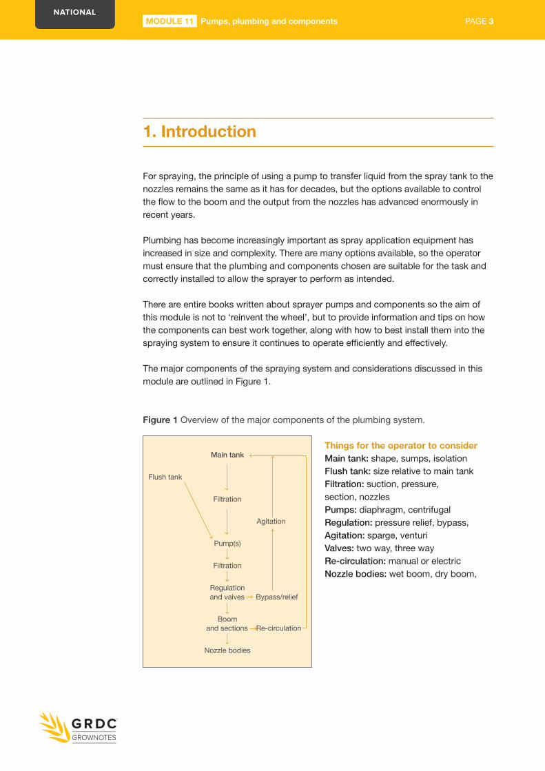
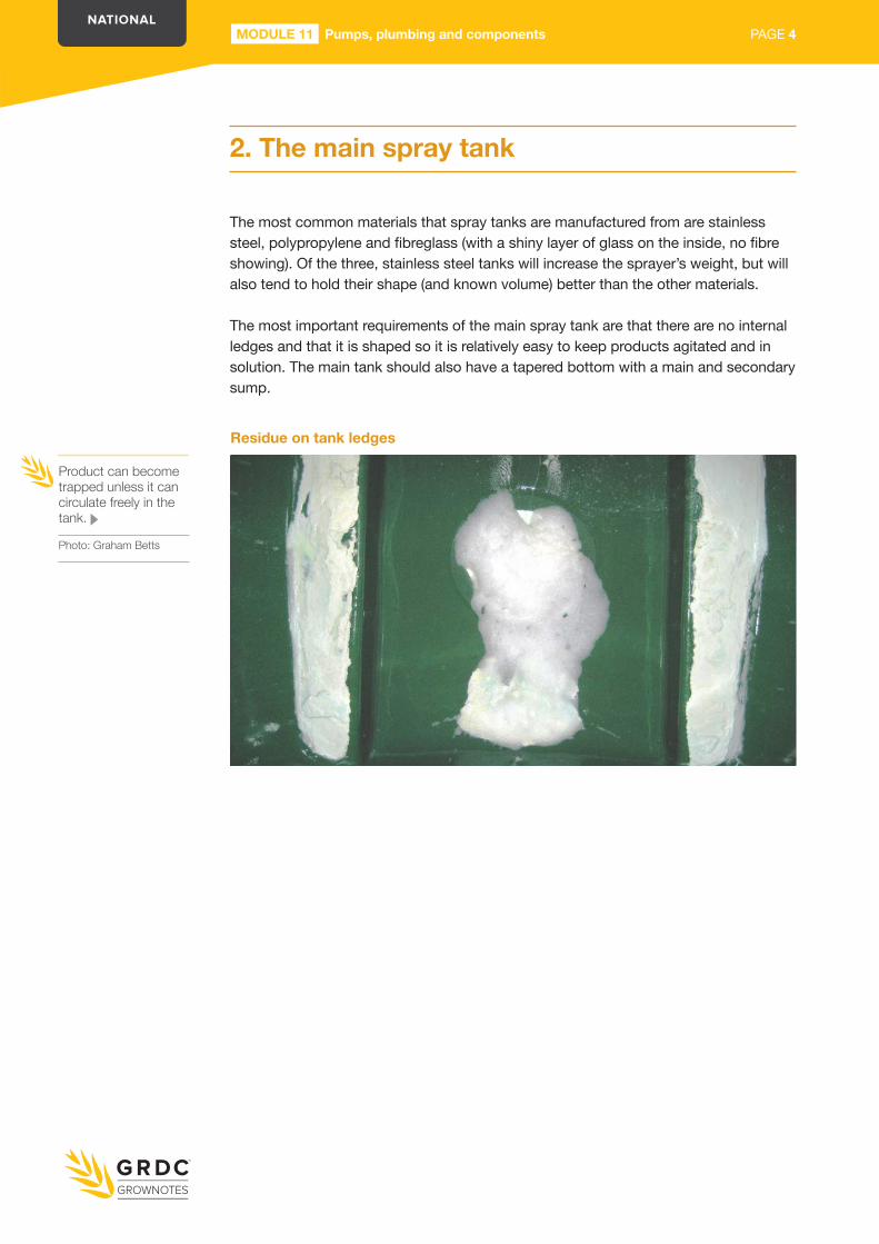
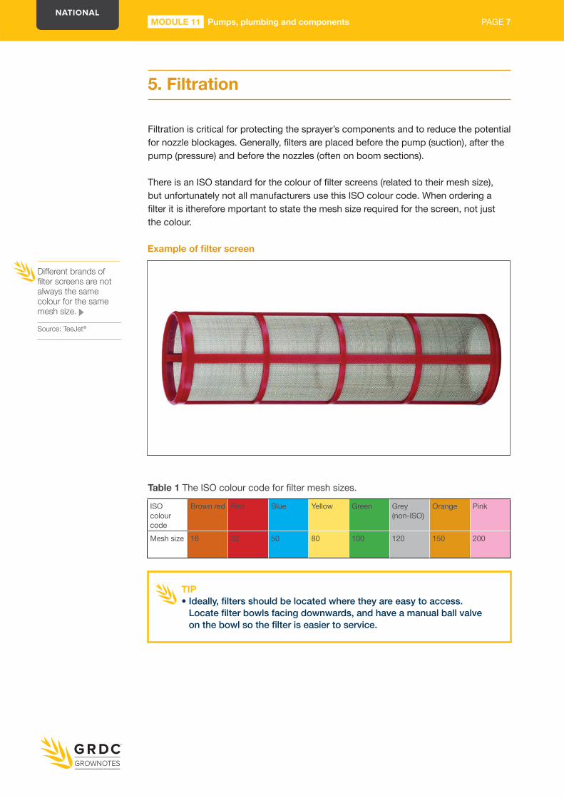
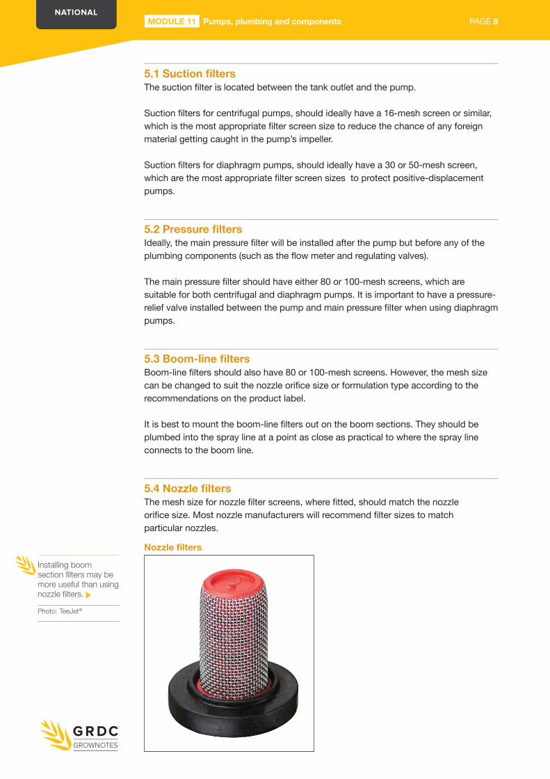
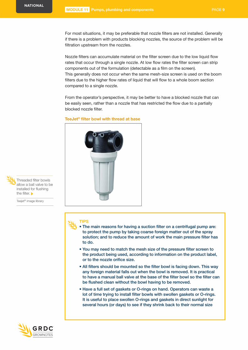
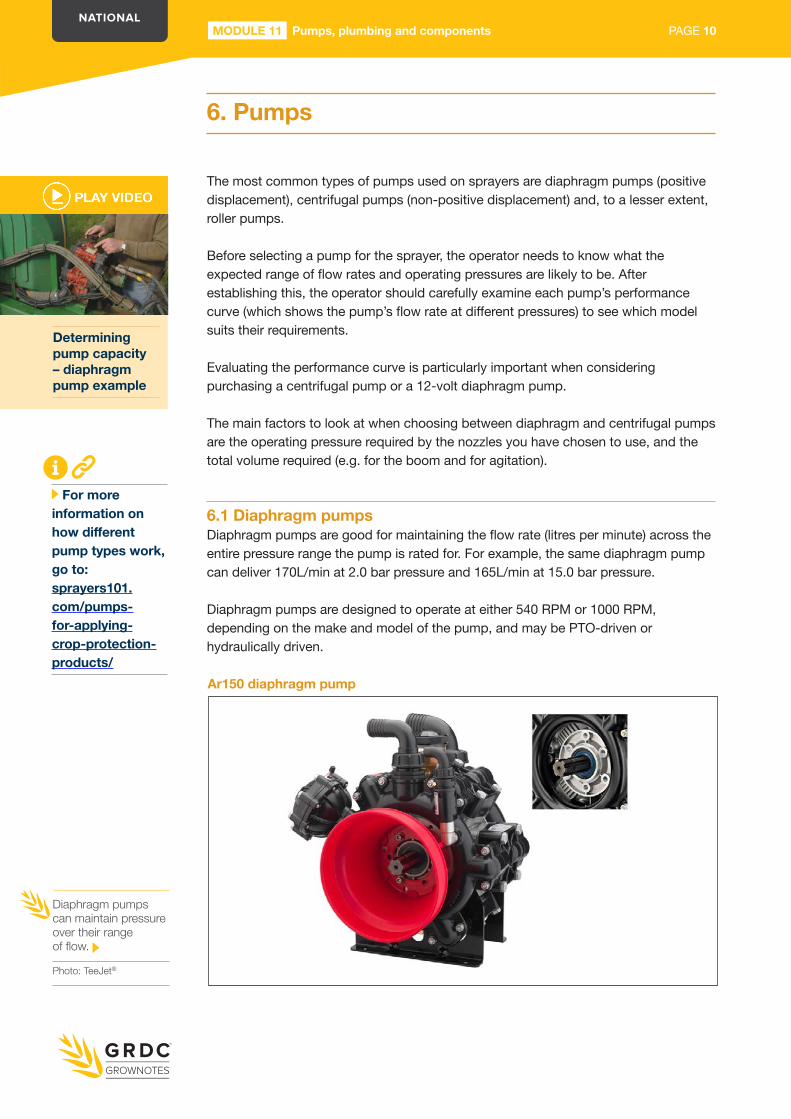
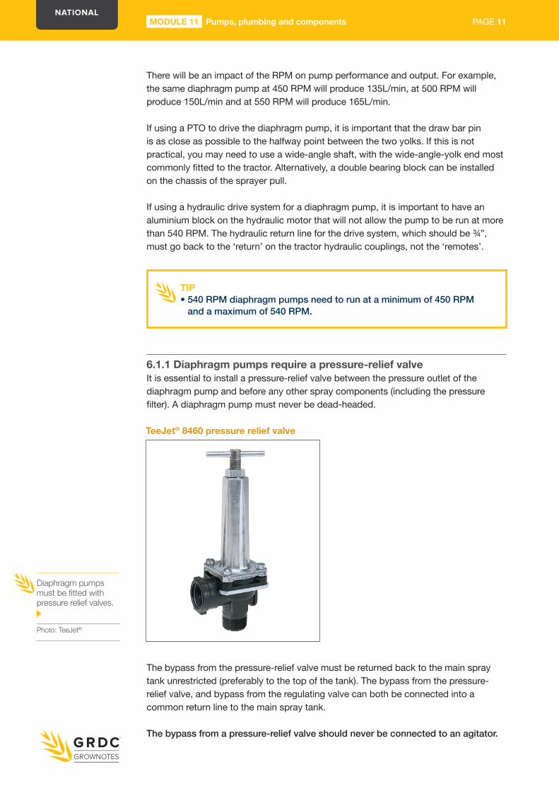
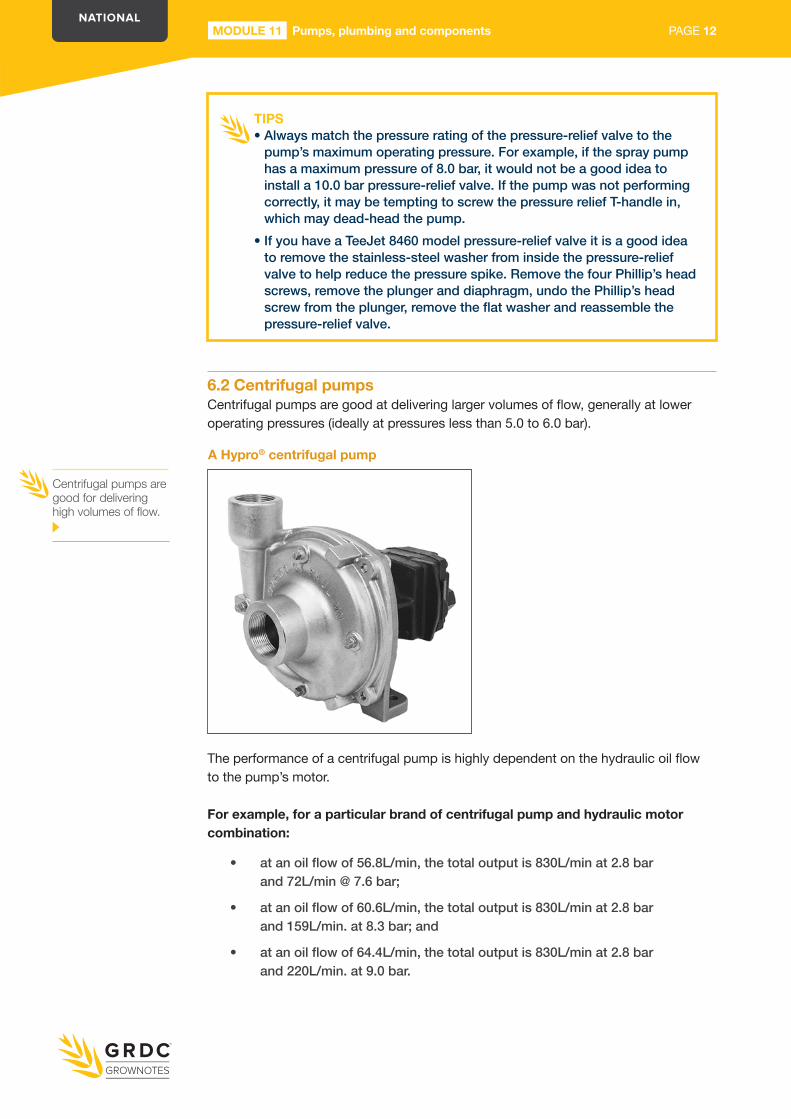
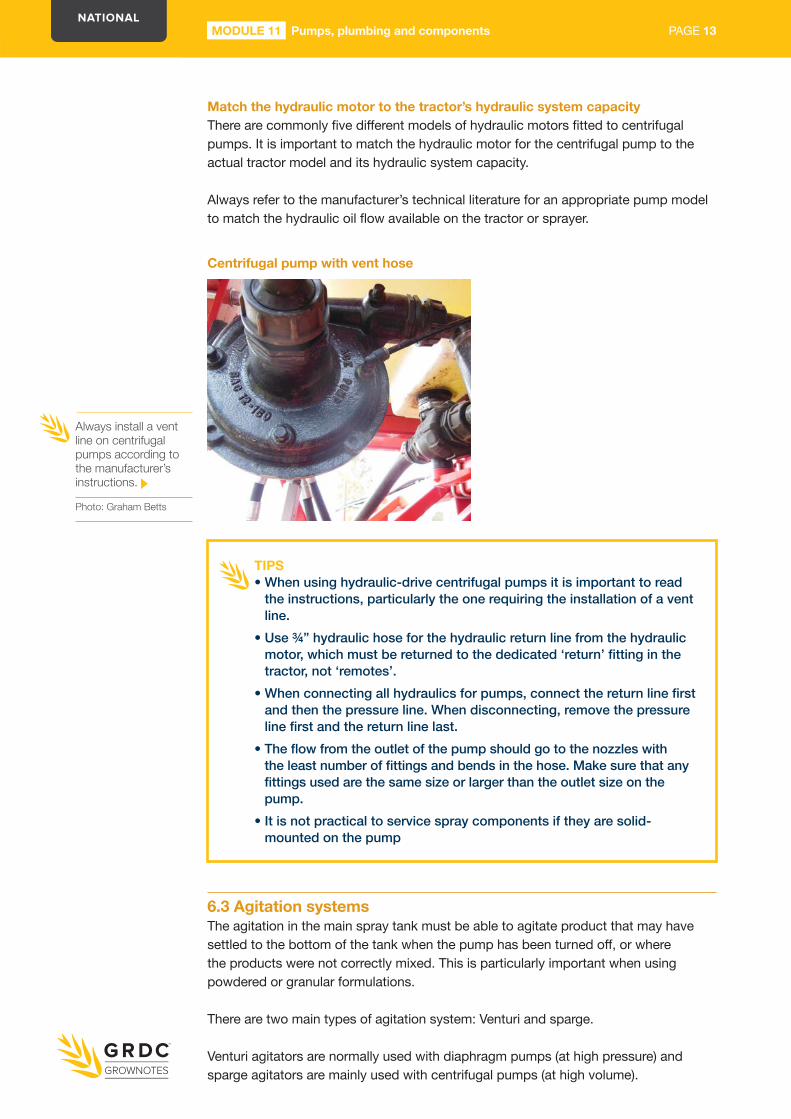
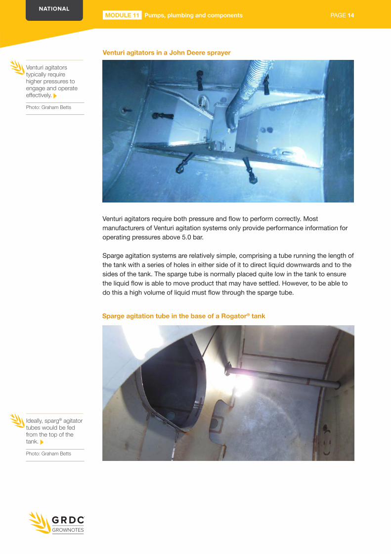
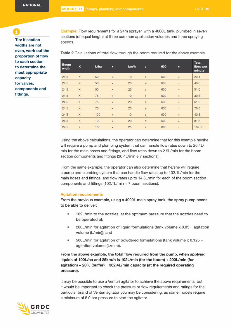
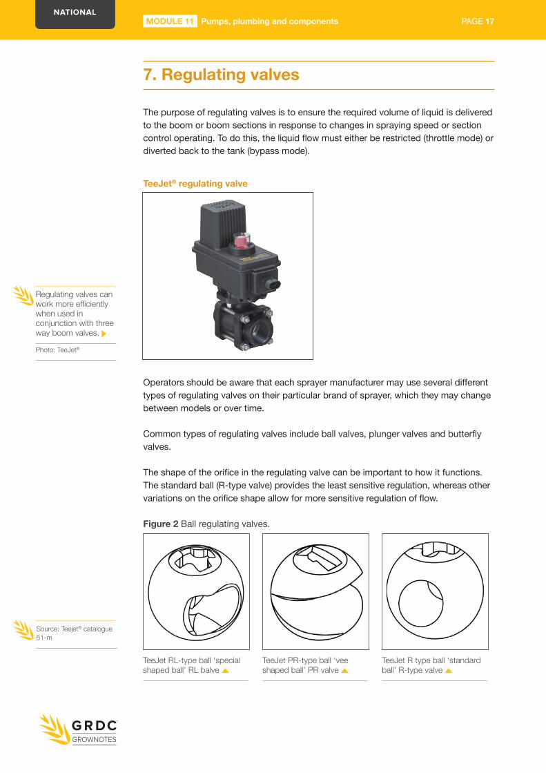
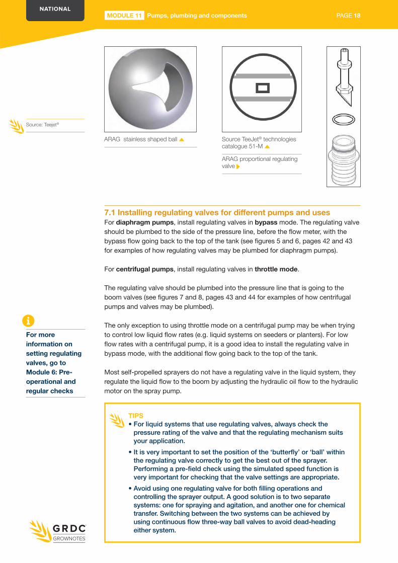
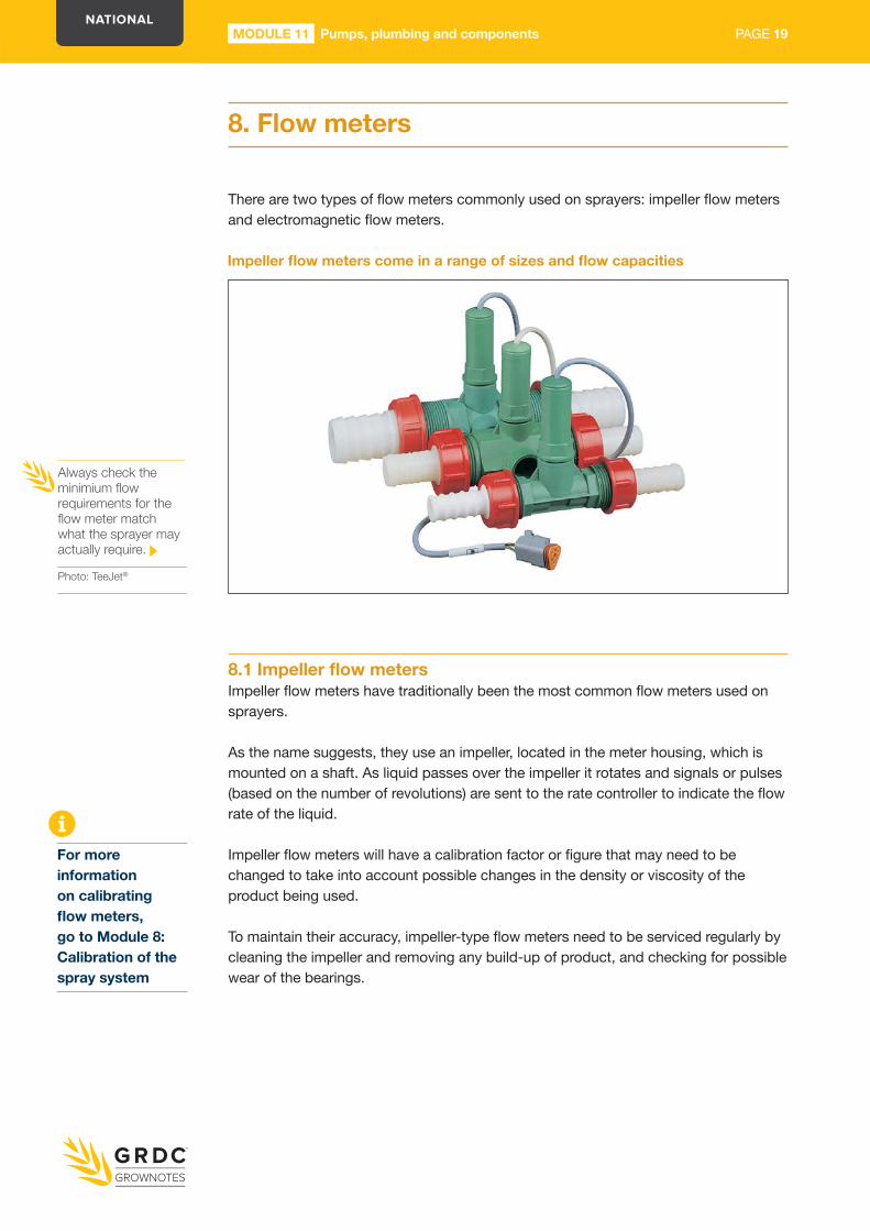
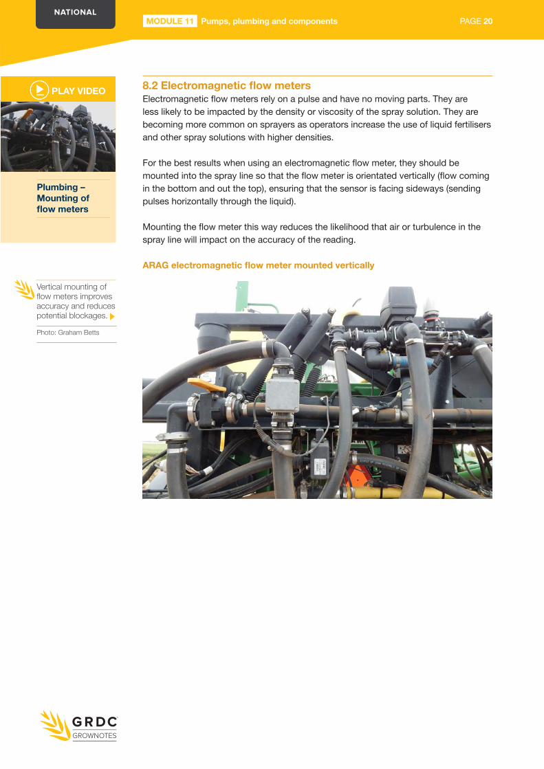
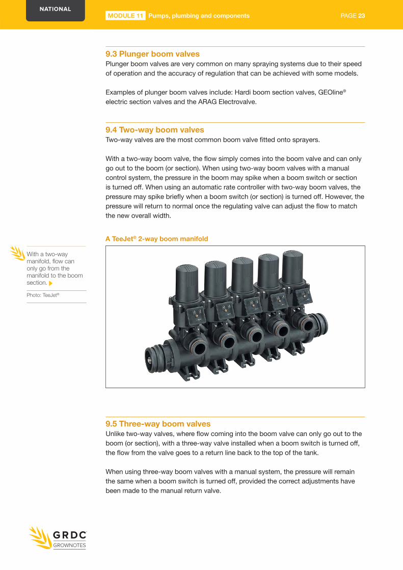
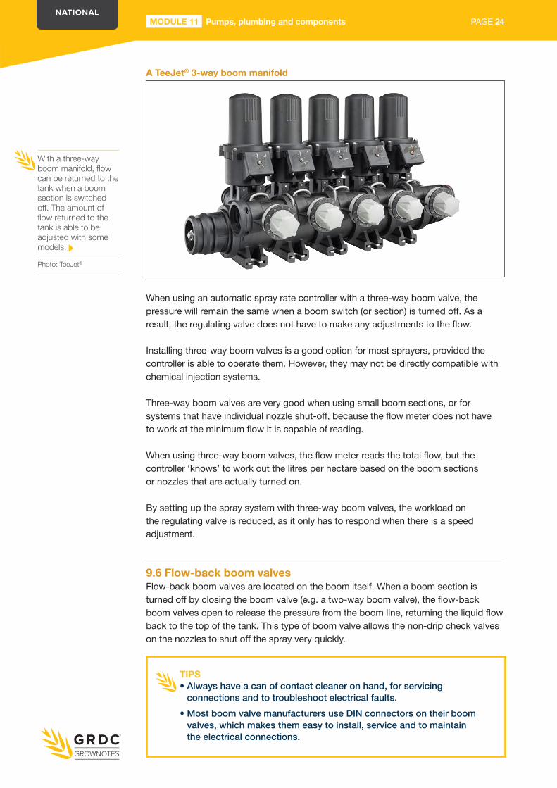
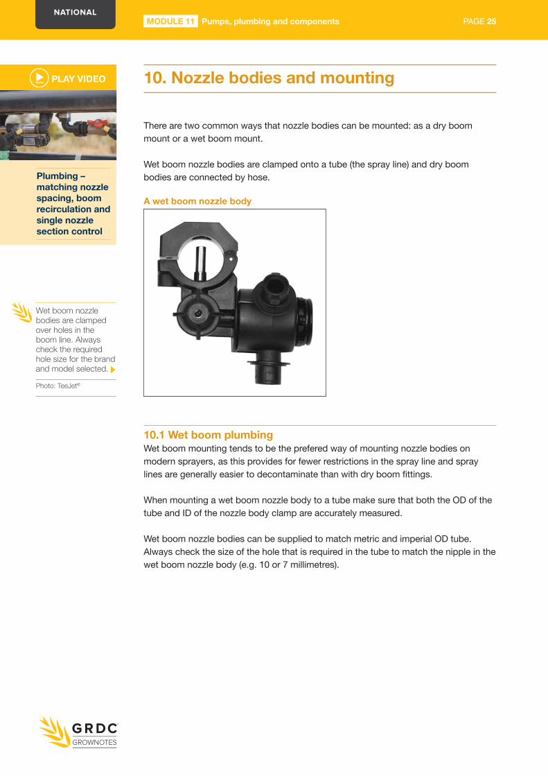
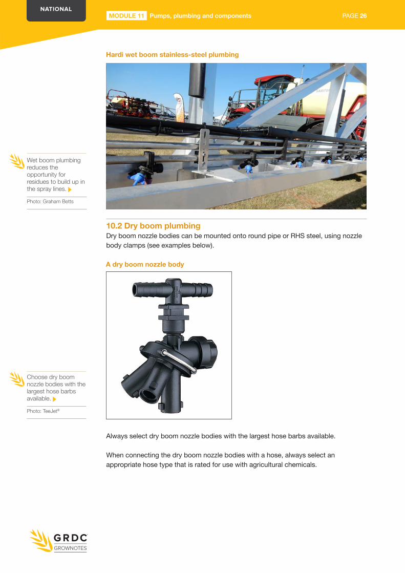
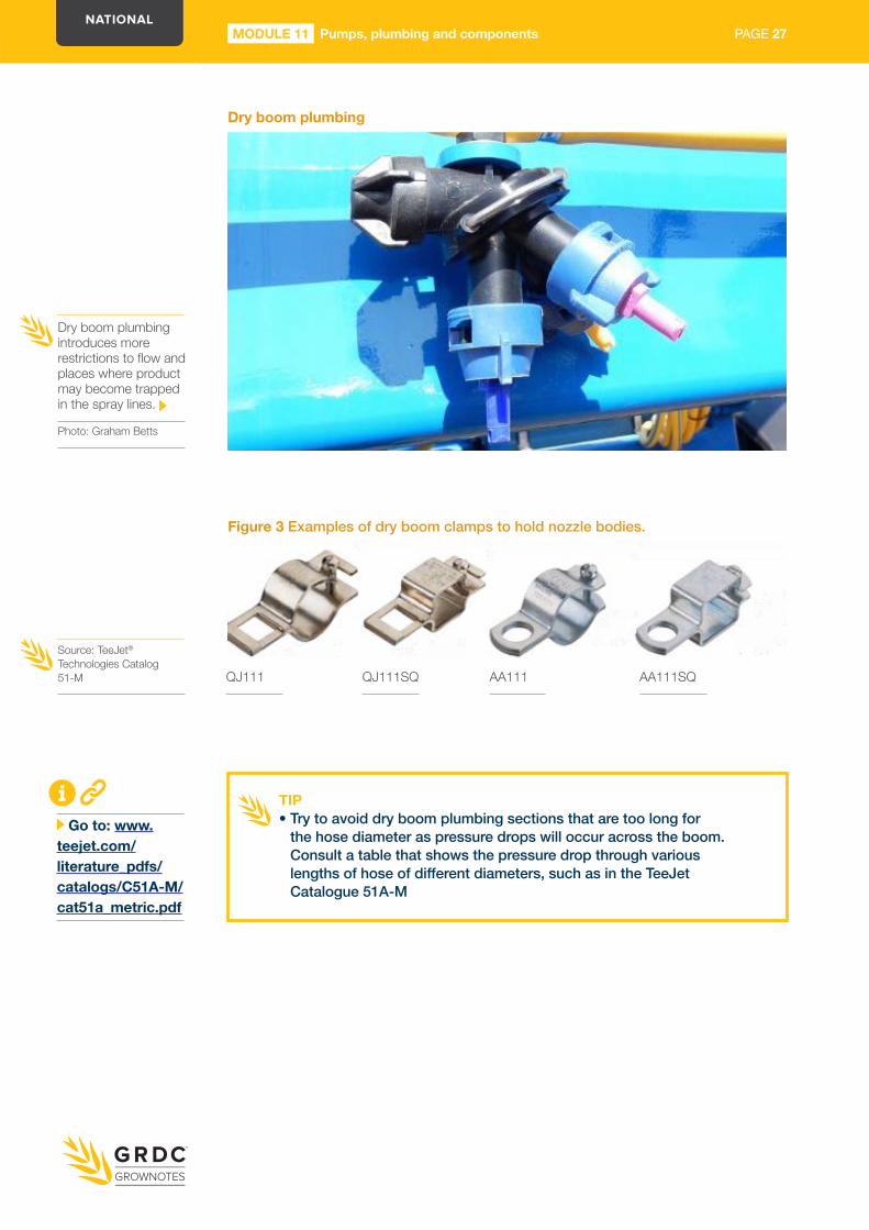
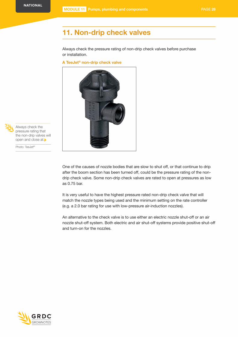
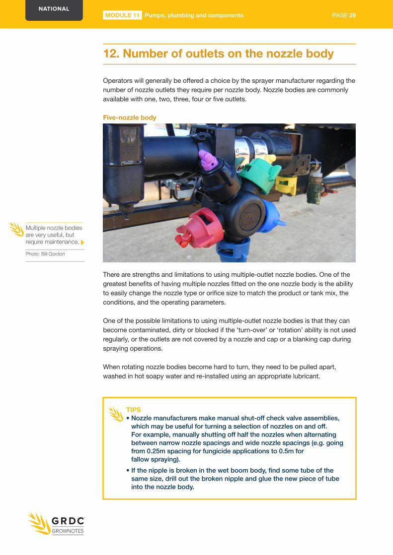
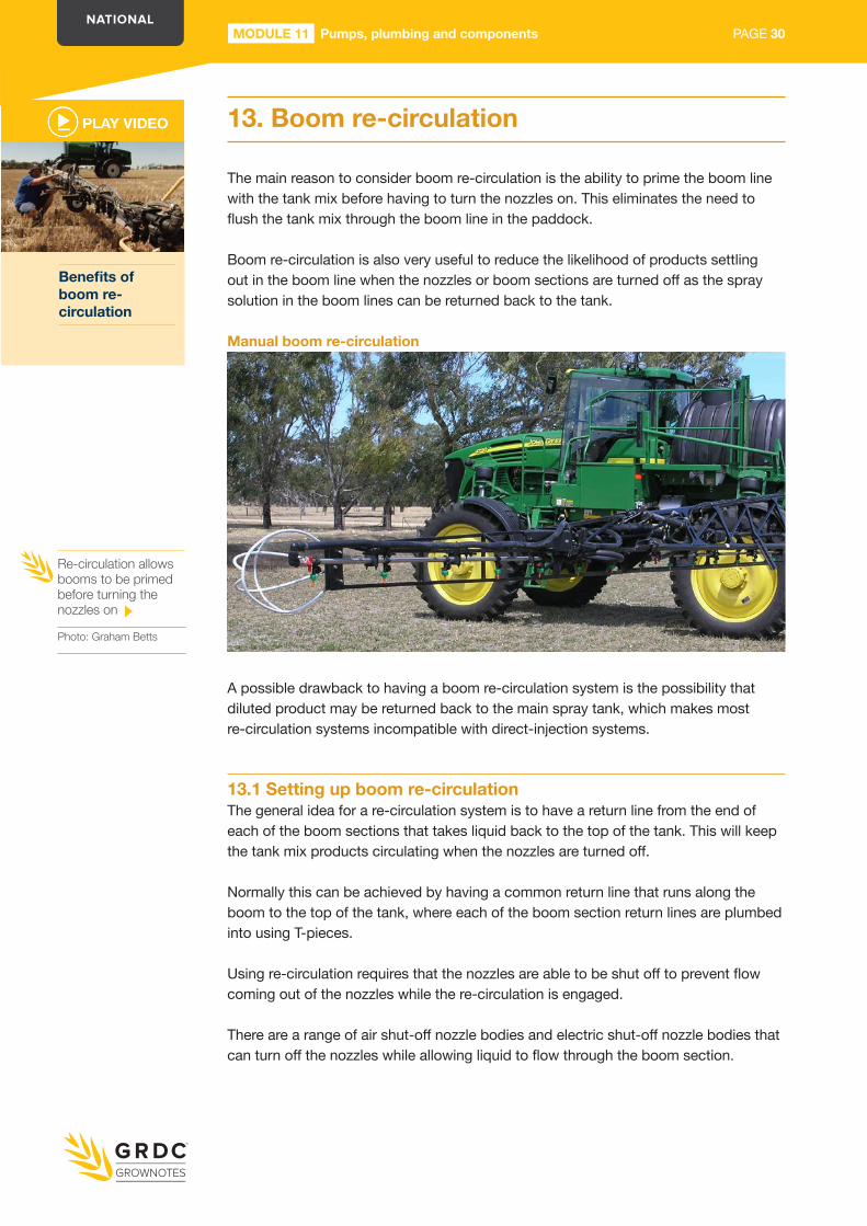
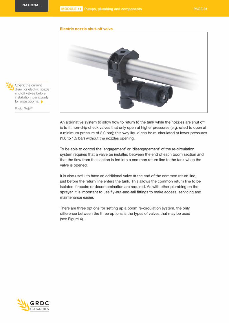
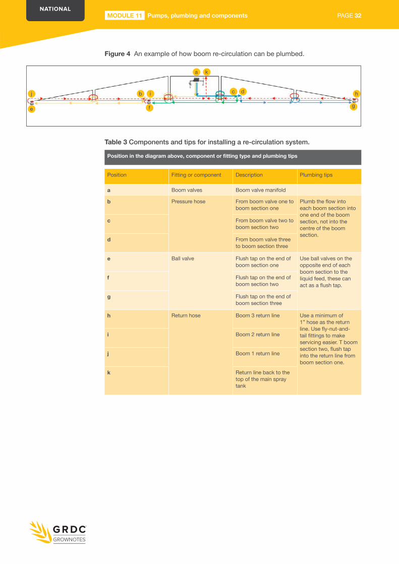
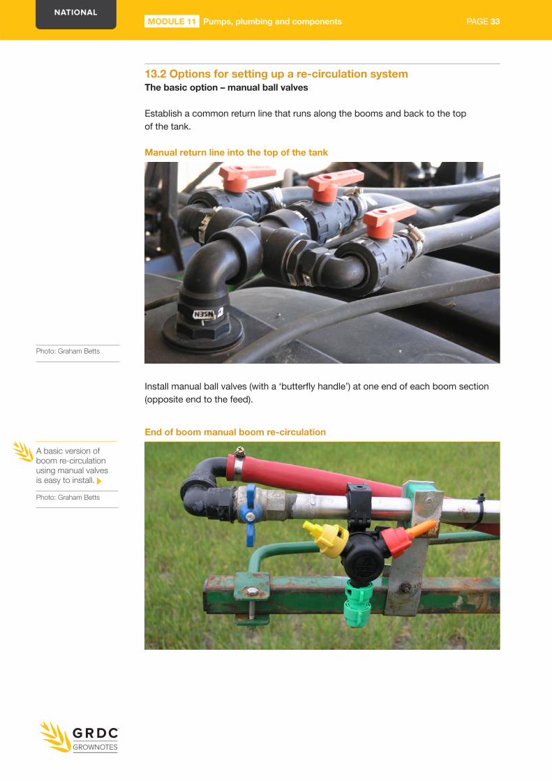
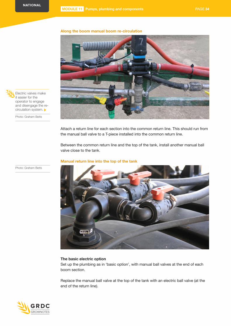
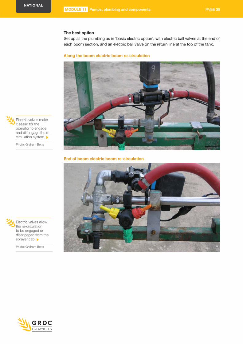