Embed Size (px)
Citation preview


Western Regional Trenchless Review 2008 3
Published by:
Suite 300, 6 Roslyn RoadWinnipeg, ManitobaCanada R3L 0G5
PresidentDavid LangstaffToll Free: [email protected]
PublisherJason StefanikToll Free: [email protected]
Editor-in-ChiefPaddy O’Toole
Advertising SalesGary BarringtonRoss JamesGladwyn NickelArlene NowickiDayna Oulion
Production services provided by:S.G. Bennett Marketing Serviceswww.sgbennett.com
Layout & DesignKathy Cable
Advertising ArtDebbie Dunmall
© Copyright 2008DEL Communications Inc.All rights reserved.The contents of this publication may notbe reproduced by any means, in whole orin part, without prior written consent ofthe publisher.
While every effort has been made to ensure theaccuracy of the information contained in andthe reliability of the source, the publisher in noway guarantees nor warrants the informationand is not responsible for errors, omissions orstatements made by advertisers. Opinions andrecommendations made by contributors oradvertisers are not necessarily those of thepublisher , its directors, officers or employees.
Publications mail agreement #40934510Return undeliverable Canadian addresses to:DEL Communications Inc.Suite 300, 6 Roslyn RoadWinnipeg, ManitobaCanada R3L 0G5Email: [email protected]
PRINTED IN CANADA 08/08
DELCommunications Inc.
W E S T T 2 0 0 8
IN THIS ISSUEMessage from the WESTT Chair Jennifer A. Glynn, P.E..................................................................4Message from the NASTT Chair Piero Salvo, P.Eng., M.Eng.. .......................................................5Message from the NASTT Executive Director Mike Willmets..........................................................62008-09 WESTT Calendar of Events ....................................................................................................72008-09 NASTT Training Courses, Chapter Events & Conferences..................................................8Fourth Annual Western Regional No-Dig Conference & Exhibition .................................................9Jacobs Associates
Going Long in Portland.........................................................................................................10
WESTT 2008-2009 Board of Directors ..............................................................................................15Horizontal Technology, Inc.
Superior Technology: At Your Fingertips Today!...........................................................16International No-Dig Show 2009: A Global Experience...................................................................18Digital Control, Inc.
Monitoring HDD Installations Made Easy With Tensitrak ........................................1917th Annual No-Dig Show, Dallas, Texas Highlights........................................................................24DCM Engineering
Geotechnical Engineering Aspects of Differing SiteCondition Claims on Trenchless Projects ........................................................................26
City of Los AngelesInnovation Method to Manage and Repair the Sewer the SMARTS© Way ..............30
Apollo TrenchlessInstalling Ductile Iron Pipe Utilizing Horizontal Directional Drilling....................33
TT TechnologiesPipe Ramming for UTA: Claude H. Nix Construction .................................................34
AkkermanMicrotunneling Equipment Prominent in Sacramento ...............................................36
Specialized Services Co.Lack of As-Builts Cause a Sticky Situation in St. Croix................................................38
AUI Inc.City of Phoenix Sewer line Relief & Replacement –Using Pipe Bursting in a Project to Increase Capacity...................................................40
INDEX TO ADVERTISERSAkkerman Inc. 36
AP/M Perma Form 15
Apollo Trenchless, Inc. 33
AUI Inc. 41
DCM Engineering 26
Digital Control, Inc. 21
Horizontal Technology Inc. IFC
IPL Technologies Inc. 22 & 23
Jacobs Associates 11
Michels Corporation 5
Pacific Multilining 6
Project Engineering Consultants Ltd. 32
Rain for Rent 32
Sanexen OBC
Specialized Services Company 39
Sprayroq Inc. 5, 13, 27, 37, IBC
TT Technologies, Inc. 12

4 Western Regional Trenchless Review 2008
WELCOME TO THE newest edition of the Western
Regional Trenchless Review! Our first two issues saw
nationwide distribution and received excellent feedback,
and we hope that this issue will continue to be a valuable
source of trenchless industry information. Thank you to all
the advertisers and article contributors for helping to make
this year’s issue a success.
There has been a changing of the guard and the introduc-
tion of new faces within our group this year. I would like to
personally thank our past Chair, Dr. Sam Ariaratnam, for all
of his hard work in establishing and growing the Western
Society for Trenchless Technology (WESTT). WESTT was
formed in 2004 as a regional chapter of the North American
Society for Trenchless Tech nology (NASTT) covering a four
state region of Arizona, California, Nevada, and New Mexico
with a volunteer Board of Directors comprised of representa-
tion from academia, government, and industry covering all
four States. I am proud to say that I have been involved with
the group from its inception and I am excited to continue to
play a role in shaping its future.
Our group’s objective is to advance the science and practice
of Trenchless Technology for public benefit; to promote and
conduct education, training, study and research for the pub-
lic benefit; and to make information readily available to all
interested and concerned parties. WESTT aims to be a “local”
source for connecting individuals interested in learning
about adoption of various trenchless techniques as a viable
solution to their infrastructure needs. Sharing of experiences
is an excellent way for evaluating the suitability of a particu-
lar trenchless method to your specific situation. Further -
more, sharing ideas amongst colleagues within our region
helps to disseminate information while building local net-
works and industry connections.
This year the Chapter will hold the Fourth Annual Western
Regional Mini No-Dig Conference and Exhibition on
October 13-14th, 2008 in downtown Sacramento, California.
The event will be held at The Holiday Inn Capitol Plaza,
which is just steps from the California Capitol Building as
well as more than 100 unique shops, restaurants and muse-
ums in Old Sacramento. The Conference will be an excellent
opportunity to learn more about trenchless methods from
technical presentations and an exhibition area featuring vari-
ous vendors from trenchless industry companies. I am excit-
ed about the networking that will take place during the event.
The Chapter is also pleased to announce a post-conference
site tour of a local large scale micro tunneling project in the
Sacramento area. Stay tuned for more details.
I look forward to another excellent year for trenchless activ-
ities in the Western region and welcome new members to join
the Western Chapter. Please feel free to contact me at
[email protected] or (925) 627-4151 or check out our
website at www.westt.org if you require any information on
WESTT or trenchless in general.
Warmest regards,
Jennifer A. Glynn, P.E.
Chairman, WESTT
JENNIFER A. GLYNN, P.E.
Message from the WESTT Chair

Western Regional Trenchless Review 2008 5
PIERO SALVO, P.Eng., M.Eng.
Message from the NASTT Chair
AS I ENTER the final stretch of my term as NASTT Chair, Iam feeling quite content with what I have seen and what isgoing on with our Regional Chapters. The WESTT society isheading into its Fourth Annual Regional No-Dig inSacramento, California. As I stated last year, their grass rootsinvolvement is a model to be looked at by other Chapters.Well done!
Once again, this year’s program is full and technicallysound. I have penciled the dates of the conference in and willbe going west!
Huge congratulations to the WESTT and their ongoing
successes and participation at the No-Digs. I expect a great
representation at the next No-Dig, the International No-Dig
in Toronto from March 29th to April 3rd 2009 at the
Sheraton Centre Toronto.
See you there!
Piero Salvo, P.Eng., M.Eng.
Chairman, NASTT
WSA Trenchless Consultants Inc.

Message from the NASTT Executive Director
MIKE WILLMETSTHIS IS MY first opportunity to
directly address the Western Society
for Trenchless Technology and to per-
sonally thank the members for their
dedication and outstanding commit-
ment to NASTT and our industry. The
strength of NASTT evolves almost
exclusively from the Chapter member-
ship and it is that volunteer spirit that
makes NASTT unique. While still a rel-
atively new chapter, WESTT members
continue to impress. That was certain-
ly witnessed at No-Dig 2008 in Dallas,
Texas where WESTT had strong repre-
sentation once again. WESTT abound-
ed from the podiums of the session
halls and from the floor of the trade
show. You have much to be proud of.
This year has presented change at
NASTT and as many of you already
know, John Hemphill, our Executive
Director for nearly a decade, has
retired. Often described as the face of
NASTT, John’s contribution to our
Society is immeasurable. Under John’s
leadership, there was significant
growth in membership, in the number
of regional and student chapters, as
well as the establishment of our high-
ly regarded training courses. John be -
lieved strongly in the peer-review
process for our No-Dig technical ses-
sions and always knew how to enlist
the expertise of our chapter members
for the Program Committee. John will
be missed and I wish him well with his
new role as Executive Director of the
International Society for Trenchless
Technology.
As the new Executive Director, I’ve
inherited something of great value and
I could not be more honoured. NASTT
is in great shape and our membership
has never been stronger. This again is
due to the extraordinary enthusiasm
of the membership and their under-
standing of the benefits of trenchless
technologies to the public and to the
environment. I look forward to work-
ing with you in the years to come and
wish WESTT the best of times with
your plans for the future.
Best wishes,
Mike Willmets
Executive Director, NASTT
6 Western Regional Trenchless Review 2008
Install CIPP linerswith NO INVESTMENT!• 4-5 times STRONGER than any felt CIPP liner• Delivered PRE-IMPREGNATED with 6 weeks shelf-life• RENT the installation equipment• Use YOUR CREW and OUR SPECIALIST!
INTRODUCING the UV Light Cured Multiliner
Pacific Multilining Inc.
33759 Morey Ave.
Abbotsford, B.C.
V2S 2W5, Canada
For more information
cal l us today!
1 800 864 [email protected]
www.multiliner.net

WESTT Events
Western Regional Trenchless Review 2008 7
2008-09 Calendar of EventsSeptember 2008
29-Oct. 3 IPLOCA 42nd Annual Convention, Athens, Greece
October 200813-14 4th Annual Western Regional No-Dig Conference & Exposition, Sacramento, CA
18-22 WEFTEC 2008 Annual Conference & Expo, Chicago, IL
20-23 Cal-Nevada AWWA Annual Fall Conference, Reno, NV
28 NASTT CIPP Course, Martinez, CA
November 20086-8 ASCE 138th Annual Conference, Pittsburgh, PA
12 NASTT New Installations Methods Course, Edmonton, Alberta
13 2008 Alberta Trenchless Technology Symposium, Edmonton, Alberta
25-28 China Bauma 2008, Shanghai, China
December 20089-10 2008 Damage Prevention Conference & Expo, Las Vegas, NV
January 200920-23 2009 UCT International Conference & Exposition, San Antonio, TX
20 NASTT HDD Good Practices Guidelines Course, San Antonio, TX
21 NASTT Pipe Bursting Good Practices Course, San Antonio, TX
February 200911-15 41st Annual Pipe Line Contractors Association Conference, Carlsbad, CA
16 NASTT Pipe Bursting Good Practices Course, Orlando, FL
17 NASTT Horizontal Directional Drilling Good Practices Course, Orlando, FL
17-19 2009 CGA Excavation Safety Conference & Expo, Orlando, FL
22-27 48th Annual Distribution Contractors Association Convention, Maui, HI
25-28 Pumper & Cleaners International Expo, Louisville, KY
27-4 Power & Communications Contractors Association 64th Convention, Hawaii
March 20094-6 NUCA Utility Construction Expo’09, Phoenix, AZ
29-3 2009 International No-Dig Conference & Exhibition, Toronto, Ontario Canada
April 20095-7 2009 ASCE Construction Research Congress, Seattle, WA
June 200914-18 AWWA Annual Conference & Exposition, San Diego, CA
August 200916-19 ASCE International Pipelines Conference 2009, San Diego, CA

8 Western Regional Trenchless Review 2008
NASTT Events
2008-09 Training Courses,Chapter Events & Conferences
Western Regional No-Dig Conference & ExhibitionMonday, October 13, 2008 – Tuesday, October 14, 2008 Holiday Inn Capitol Plaza – Sacramento, CaliforniaSponsored by the Western Society for Trenchless Technology(WESTT)CONTACT INFO:Website: http://www.westt.org Jennifer GlynnEmail: [email protected]
Horizontal Directional DrillingGood Practices Guidelines (HDD) CourseTuesday, January 20, 2009Henry B. Gonzalez Convention Center
– San Antonio, TexasSponsored by the North American Society for TrenchlessTechnology (NASTT) CONTACT INFO:
Website: http://www.uctonline.com Angela Ghosh, NASTTPhone: 703-217-1382Email: [email protected]
NASTT Pipe Bursting Good Practices CourseWednesday, January 21, 2009Henry B. Gonzalez Convention Center
– San Antonio, TexasSponsored by the North American Society for TrenchlessTechnology (NASTT)CONTACT INFO:
Website: http://www.uctonline.com Angela Ghosh, NASTTPhone: 703-217-1382Email: [email protected]
NASTT Cured-in-Place-Pipe (CIPP)Good Practices CourseWednesday, January 21, 2009Henry B. Gonzalez Convention Center
– San Antonio, TexasSponsored by the North American Society for TrenchlessTechnology (NASTT) CONTACT INFO:
Website: http://www.uctonline.com Angela Ghosh, NASTTPhone: 703-217-1382Email: [email protected]
NASTT New Installation MethodsGood Practices CourseThursday, January 22, 2008Henry B. Gonzalez Convention Center
– San Antonio, TexasSponsored by the North American Society for TrenchlessTechnology (NASTT) CONTACT INFO:
Website: http://www.uctonline.com Angela Ghosh, NASTTPhone: 703-217-1382Email: [email protected]
NASTT Laterals Good Practices CourseThursday, January 22, 2008Henry B. Gonzalez Convention Center
– San Antonio, TexasSponsored by the North American Society for TrenchlessTechnology (NASTT) CONTACT INFO:
Website: http://www.uctonline.com Angela Ghosh, NASTTPhone: 703-217-1382Email: [email protected]
2009 International No-Dig Conference & ExhibitionSunday, March 29, 2009 – Friday, April 3, 2009 Sheraton Centre Toronto – Toronto, Ontario CanadaSponsored by the North American Society for TrenchlessTechnology (NASTT) and the International Society forTrenchless Technology (ISTT)CONTACT INFO:
Website: http://www.nodigshow.comBenjamin Media, Inc. (Conference Management)Phone: 330-467-7588Email: [email protected]


10 Western Regional Trenchless Review 2008
JACOBS ASSOCIATES
THE EAST SIDE Combined SewerOverflow (CSO) Tunnel Project willconvey captured flows from SoutheastPortland to a pump station on SwanIsland, traveling under a busy industri-al area along the Willamette River. Themain tunnel is being constructed at adepth ranging from 100 to 160 feetand, when finished, will be approxi-mately 30,000 feet long with a finishedinside diameter of 22 feet. The maintunnel will function as a storage andconveyance conduit, intercepting aseries of gravity conduits and dropstructures that will collect flows from13 of the system’s existing outfalls.Flows from several of the existing out-falls will be conveyed to the new tunnelvia nine 84-inch-diameter reinforcedconcrete pipe microtunnels. The nine
microtunnel drives total approximately7,825 linear feet. One of the drives, theOutfall 46 drive, is a 3,055-foot-longmicrotunnel that was completed inApril 2008. It is currently the longestmicrotunnel driven in the UnitedStates. The Outfall 46 alignment passesbetween an active railroad yard and acement storage and shipping facility.
The $426 million East Side CSOTunnel Project, constructed by theJoint Venture of Kiewit-Bilfinger Berger(KBB), is scheduled for completion in2011. Jacobs Associates assists theowner, Portland’s Bureau of Environ -mental Services (BES), with construc-tion management (CM) services,including contract administration andresident engineering. Craig Kolell,Associate at Jacobs Associates, provides
CM services to the bureau for themicrotunnel and pipeline work on theEast Side CSO Tunnel Project. Mr.Kolell has over 24 years in the heavycivil construction industry, focusing ontunneling and microtunneling opera-tions. He recently served as AssistantConstruction Manager for the success-ful West Side CSO Tunnel project inPortland, Oregon. Christa Overby,Field Engineer for BES, now supervisesall of the East Side CSO microtunneland pipeline construction after work-ing as Task Lead on the design. Ms.Overby has over 10 years of experiencein civil design and construction. Thesuperintendent responsible for the pre-planning and management of themicrotunnel operations for KBB isMatt Roberts. Mr. Roberts has over 15years of experience in the heavy civilconstruction industry, focusing onunderground construction.
Geologic ConditionsThe Outfall 46 drive was driven
through two geologic units: artificialfill (Qaf) and sand/silt alluvium (Qaland Qff). These two units were definedin the GBR as follows:• Artificial Fill (Qaf) mostly consists of
gravel, sand, sandy silt, and silt withorganic debris. However, in this case,it will also contain building debris,abandoned steel rails and timber rail-road ties, concrete, logs, and woodwaste including sawdust, branches,wood chips and fragments. Fill com-position will vary within the projectarea depending on previous site-use.
By Craig Kolell, Jacobs Associates;Christa Overby, City of Portland;
and Matt Roberts, Kiewit-Bilfinger Berger JV.
GOING LONGIN PORTLAND
A 24-foot-diameter, 54-foot-deep secant pile shaft with a jet grouted plug in the bottomwas constructed for use as a jacking shaft.

• Sand/Silt Alluvium (Qal and Qff) pre-dominately comprises interbeddedsandy silt and silty fine sand deposit-ed as recent alluvium (Qal) and latePleistocene fine-grained catastrophicflood deposits (Qff). They are typical-ly non-plastic to low plasticity, butsome zones of moderate to high plas-ticity elastic silt are found. Some grav-el lenses are also found in this unit.The alluvium is typically stratifiedwith alternating layers of fine sand,sandy silt, silt, and clayey silt. The con-sistency of the alluvium is most oftendescribed as soft to medium stiff forfine-grained layers or loose to medi-um dense for coarse-grained layers.Organic material was encounteredduring drilling within the Sand/SiltAlluvium, especially in sloughs andgulches. Organic material commonlyconsists of organic silts, wood frag-ments, logs, and wood debris.
Design ConsiderationsA slurry pressure microtunnel boring
machine (MTBM) was required to pre-vent the soil from running or flowinguncontrollably into the machine face.Slurry microtunnelling minimizesground water drawdown and providespositive face support, thereby minimiz-ing the effects of tunneling on nearbystructures and utilities. The MTBM iscapable of supporting the soil exposedin parts of the face while cutting harderlayers and concretions in other parts. Itis equipped with a stone crusher anddisc cutters to break up boulders withcompressive strengths up to 55,000 psi.A manlock was included to allow hyper-baric interventions for removal ofobstructions and changes to cutterheadtools.
The original design for the Outfall 46drive called for two microtunnels of1,934 feet and 991 feet respectively, withan intermediate shaft. During construc-
Western Regional Trenchless Review 2008 11
A three chambered structure was builtaround the existing 78-inch outfall pipe.
The existing pipe will be removed andan elbow will be placed diverting flows
into the 84-inch microtunnel limitingflows into the river.
JACOBS ASSOCIATES

tion, KBB proposed eliminating the intermediate shaft. Itshould be noted that the construction contract is cost reim-bursable fixed-fee with labor, equipment, and materialspaid by the owner as reimbursable costs. BES accepted thehigher calculated risk of the long drive, which broughtpotential cost savings from the elimination of the interme-diate shaft. The decision was based on BES’ experience withmicrotunneling on the West Side CSO Project in similarground conditions and with a similar machine along with
the technical feasibility performed forthis long drive by KBB. The advantage ofthe longer drive to KBB was the schedulesavings from the elimination of theshaft, which was located in a difficultposition with limited space. After thedecision was made, design modificationswere made to the MTBM system to sup-port the longer alignment, includingchanges to the slurry system, intermedi-ate jacking stations controls, and electri-cal equipment.
ConstructionAn AVN 2000D machine built by
Herrenknecht Tunnelling Systems waspurchased for the project. The 104-inch-diameter cutting wheel can rotate inboth directions to compensate for anyrolling of the machine caused by reac-tion to the torque of the cutting wheel.Situated in the shield directly behind thecutting wheel, the excavation chamberprocesses all excavated material, crush-ing it to a grain size suitable for trans-portation by slurry circuit. The con-veyance of the excavated and crushedmaterial is undertaken in a slurry sus-pension. A feed pump pushes this sus-pension through a feed line into theexcavation chamber, where it mixes withthe excavated material. Then the mixturegets pumped via slurry pumps to theseparation plant at the ground surface.The separation plant disjoins the materi-al and slurry suspension. The addition ofbentonite allows the density and viscosi-ty of the slurry suspension to be varied tosuit geological conditions.
The jacking shaft was a 24-foot-diame-ter, 54-foot-deep secant pile shaft with ajet grout bottom plug. Due to space lim-
Typical Intermediate Jacking Station with special trailing pipeinstalled.
12 Western Regional Trenchless Review 2008
JACOBS ASSOCIATES

Western Regional Trenchless Review 2008 13
1
itations at the bottom of the shaft, a platform was erected 10feet off the bottom for the slurry pump. A 1,100 ton indexingjacking frame was used to handle the 10-foot pipe sections.
The receiving shaft is located at the existing 78-inch outfallthat will eventually divert flow into the microtunnel. The floorand walls of the structure were completed prior to the driveand the MTBM was removed from within the 14 foot wide by18 foot long chamber in the structure. An 11 by 11 foot open-ing was left in the diversion structure wall to allow for thebreak in.
Because of the length of the drive, seven 1,100 tonIntermediate Jacking Stations (IJSs) were used. The length ofthe drive also required some additional electrical equipment beset in the pipes behind the machine. Therefore, the first IJS wasinstalled approximately 150 feet behind the machine.Subsequent IJSs were installed approximately every 420 feet.The jacking forces slowly increased from 150 to 250 tons toapproximately 700 tons towards the end of the drive. 900 to1,000 tons was sometimes required to start the pipe movingagain after down time for adding pipe, surveying, or mainte-nance. On most pushes, only one or two IJSs were needed.
Tunneling of the Outfall 46 drive started on February 14,2008 and was completed on April 19, 2008. At the start of thedrive the high silt content in the ground required some modi-fications to the separation plant equipment and handling pro-cedures. Production rates were reduced when wood piles andmiscellaneous pieces of metal — including large spikes, nails,and bolts were encountered. The average daily production wasapproximately 54 feet per day, with production on the best daybeing 152 feet. No hyperbaric interventions were required andno cutterhead tools needed to be replaced.
The 3,055-foot Outfall 46 drive is now the longest micro-tunnel ever driven in the United States. Like most rewardingtunneling achievements, it was accomplished through hardwork and long hours by a team of laborers, operators, engi-neers, and managers. Most importantly, it was completed safe-ly. Three hundred and six pieces of undamaged pipe wereinstalled with no injuries. ❍
2
3
1: Close-up of the cutterhead showing silty sand and some wooddebris left on picks and bucket lip. 2: A good representation of the mix
of soil and shredded wood piles excavated by the MTBM.3: The MTBM hole-through on April 19, 2008.
JACOBS ASSOCIATES

WESTT
Jennifer Glynn, ChairpersonConsultants
RMC Water and EnvironmentWalnut Creek, CA
Matthew Wallin, TreasurerConsultants
Bennett Trenchless EngineersSacramento, CA
Dr. Samuel Ariaratnam, AdvisorAcademia
Arizona State UniversityTempe, AZ
Ron Ablin, DirectorConsultants
Brown and CaldwellPhoenix, AZ
Craig Camp, DirectorConsultants
Jacobs AssociatesSan Diego, CA
Richard Davis, DirectorConsultants
Stanley Consultants Inc.Las Vegas, NV
Collins Orton, DirectorManufacturers/Suppliers
TT Technologies Inc.Redwood City, [email protected]
Cindy Preuss, DirectorConsultants
Harris & AssociatesConcord, CA
Paul Reilly, DirectorManufacturers/Suppliers
Rain for RentBakersfield, CA
Michael Rocco, DirectorContractors
AUI IncorporatedAlbuquerque, [email protected]
Mike Stram, DirectorOwners
City of RenoReno, NV
Robert Webb, DirectorConsultants
Project Engineering ConsultantsPhoenix, AZ
Western Society for Trenchless Technology (WESTT)BOARD OF DIRECTORS (2008-2009)
Suite 300, 6 Roslyn RoadWinnipeg, Manitoba R3L 0G5
Toll Free:1.866.831.4744 | Toll Free Fax: 1.866.711.5282
www.delcommunications.com
DIRECTORIES
TRADE PUBLICATIONS
ADVERTISING DESIGN & LAYOUT
QUALIFIED SALES & EDITORIAL TEAM
DEL Communications Inc. has in excess of100 years combined experience working for you.
We offer outstanding personal serviceand quality in the areas of...
Western Regional Trenchless Review 2008 15

16 Western Regional Trenchless Review 2008
HORIZONTAL TECHNOLOGY, INC.
SINCE THE INCEPTION of HDD, the desire for advancedtechnology has dominated the mind-set of the industry. Thebasic story is simple. The competition for early contractorswas not each other but the task of convincing the construc-tion world that Horizontal Directional Drilling was a viableinstallation method. Contractors honed their skills with com-paratively few projects and usually in remote areas. About1988, guidance capabilities advanced giving the operator theability to precisely locate the steering tool below the surface.Prior to this, no one ever knew where the drill bit was locateduntil it exited the ground, severely limiting the areas thatHDD was feasible. By positioning an artificial magnetic fieldon the surface, the precise location of the steering tool belowthat field could be determined. The steering software offeredprecision beyond expectations. The advent of surface trackingallowed HDD contractors to know the location of the drill bitat all times. This was a gold-mine for the developer but a big-ger boom for the HDD industry, creating the ability to installlines safely in congested areas. Things changed quickly.
Few newcomers understood that the catalyst for the indus-try’s amazing expansion was steering accuracy, but entrepre-neurs recognized the opportunities and wanted in. The com-plexion changed rapidly and competition required contrac-tors to do one of two things, be low bidder or promise sometype of an advantage to their client. Industry growth created asevere experience shortage that affected the industry at all lev-els. Pipeline companies had very little HDD experience andwere looking to an ever growing number of contractors withequally diluted expertise for advice. “Cowboy” contractorswere financing rigs, pulling onto locations and drilling aheadwith little or no planning. HDD standards were being loweredacross the board. The steering specialist, a position previouslyrequiring years of experience, was now open to anyone whowould take the job.
In addition, a version of surface tracking, previously dis-
carded as inferior, was being misleadingly promoted as a sin-gle wire system, marketed as newer and faster. To contractorswho knew nothing about steering tools or the physics of howthey worked, new meant better. Owners and engineers alikemistakenly assumed wire-line steering was all the same.Without question, there must be an advantage to anythingnew. Nothing could have been farther from the truth. Theresult was that many tools were sold and hundreds of linesinstalled using a system inferior to established industry stan-dards. How did this occur? Contractors wanted a competitiveedge and someone promised them one. In a quote usuallyattributed to Mark Twain, “A lie will travel around the worldbefore the truth can get its boots on.”
The experience shortage was across the board and a hin-drance to the industry, but it created an opportunity for thetruly knowledgeable veterans to offer consulting services toboth pipeline owners and contractors. Even here, expansionexceeded available personnel, allowing overnight-experts tofill the void. Knowledgeable HDD consulting firms werequickly in competition with less knowledgeable, but enthusi-astic hustlers who promised the same service for less. If youknew a little of the terminology and had the gumption to callyourself an expert, you were in business.
The result was inexperienced HDD contractors using inferi-or steering methods, working under the supervision andinstruction of less experienced, and sometimes unscrupulous,consultants. (Some consulting firms found ways to siphon acommission from the drilling tools or service companies theyrequired contractors to use.)
Two decades later, the experience-level is finally starting toclose the gap. People are finally starting to ask questions. Ahealthy dose of skepticism is beginning to take hold.Contractors and, more importantly, engineering firms, arebeginning to realize how good the technology is and that allwire-line steering is not equal. The search for the “magic-bean”has been replaced by requirements of planning and design.Owners and engineers have learned the hard way that a mag-netic beacon or an AC wire laid across the surface is inept andinaccurate, especially when compared to the DC tracking sys-tem responsible for the industry’s tremendous expansion. Alllevels of HDD management are learning that accurate steeringrequires proper set up, planning and experience. Almost noone who purchased the new AC system, or required a contrac-tor to use it, wants to acknowledge that the accuracy is inferi-or to the established tracking method and that the actual loca-tion of many of those lines will need to be re-established.
By John English, Horizontal Technology, Inc.
SUPERIOR TECHNOLOGY:AT YOUR FINGERTIPS TODAY!
At Horizontal Technology, Inc., training never stops.

Western Regional Trenchless Review 2008 17
That’s right; the equipment that most of these companiesalready owned was more accurate than the new method theypurchased. Some projects installed with the “new” systemhave already had to be re-drilled using the more accurate DCtracking method. Contractors have had to absorb thesetremendous costs. Many right-of-ways are possibly unusablefor additional lines because the precise location of existingHDD crossings is unknown. Who knows how many lines areactually off the right-of-ways and what the costs of futurecourt cases will be?
Owners and consulting firms are learning the key to a suc-cessful drill is planning and that nothing is more accuratethan a precise DC based job set up and operated by an experi-enced, well trained steering person. The lifeline of HDD isaccuracy, and we have the most precise guidance method avail-able at our fingertips today.
In many cases, shortcuts and the search for a technologicaledge had replaced planning and proven HDD methods. As theindustry matures, this trend is slowly being reversed. TheHDD industry has always relied on the drilling technologydeveloped by the Oil & Gas industry, but the oilfield has neverabandoned their proven drilling techniques or well planning.Oilfield-developed drill motors, drill bits and steering toolsare only a few of the essentials required for installing HDDlines. In our industry, references to the oilfield technology andadvancements are made on a daily basis, but few understandthe technology already available to HDD contractors. In fact,because of surface tracking, the drilling accuracy available andrequired in our industry far exceeds that available in the Oil &Gas industry. The most important thing we can copy from theOil & Gas Industry is planning and record keeping. Thisremains the most notable difference between our industriesand is the Achilles heel of HDD. Professionalism is dependenton improved planning and documentation.
There are many professional HDD contractors. Contractorsare learning that the key to profits is planning and open com-munication with the inspectors and owners. The more profes-sional the HDD industry becomes, the quicker the competi-tion will thin and allow pricing to reach a more realistic stan-
dard. The secret is planning and the use of proven HDDmethods. By definition, technology must be an improvement,not new or different. If it isn’t better than what exists it is sim-ply regression. Today’s technology includes advanced steer-ing and intersect software, automated reports that can beemailed direct to the inspectors and owners after every survey,pressure tools that record annular and drill-pipe pressures,planning software that works with time-saving data collec-tors and documentation to record all relevant information,just to name a few.
Unchecked growth had resulted in the industry taking anumber of backward steps; the most significant being relatedto guidance and accuracy. Things are changing. Engineeringfirms and owners are learning that the pull-up and drill atti-tude is costing them time and money, not to mention a life-time of uncertainty and liability. Proper HDD techniques taketime, and the planning must occur before the project is mobi-lized. This investment in professionalism is preventing post-bore arguments and improving directional accuracy throughbetter documentation. Talking about new technology is onething, but the use of proven technology takes planning anddiscipline. Successful contractors are rediscovering HDD tech-nology developed by the industry pioneers. Owners and engi-neering firms are asking the right questions and demandingthe best HDD technology and methods be used. For the firsttime in a long time, directional projects are being designed toenhance the guidance accuracy while improving the chancesof a successful completion. The results are improving profitsfor everyone. ❍
1: Taking the time to establish a base line azimuth. 2: Workingin congested areas requires the most accurate steering available.
3: The result of a detailed set-up.
1 2
3
HORIZONTAL TECHNOLOGY, INC.

18 Western Regional Trenchless Review 2008
DearTrenchless
Professionals, You know that
excited feeling youget when you hear peo-
ple talking about a conference a year inadvance? The momentum is building.People are getting excited. People wantto get involved. That is what’s happen-ing for the International No-Dig Showslated for 29 March – 3 April, 2009, inToronto. This year’s No-Dig Show istruly special as NASTT is very proud tobe co-sponsoring this worldwide eventwith the International Society forTrenchless Technology (ISTT).
The International No-Dig Show pro-gram is driven and developed by agroup of NASTT and ISTT memberscalled the Program Committee. Theirspirit of volunteerism and hard workwill result in a high-quality informa-tion exchange for everyone who willattend in Toronto. By the time you readthis letter, our planning committee hasalready met to review abstracts and lay-out the technical paper program.
Nearly 200 high-quality abstractswere submitted for consideration, sur-passing the number of abstracts sub-mitted in past years. This outpouringof interest indicates strong growth inthe trenchless technology industry –not only here in North America – butalso from around the world. Inter na -tional papers from Denmark, France,Germany, Italy, Japan, Poland, Taiwan,the Netherlands and the United
Kingdom will be presented, showcasinginnovative new ideas in the globaltrenchless marketplace. (All papers willbe presented in English.)
No-Dig attendees may choose toattend from amongst 140 of the mostinteresting and compelling papers pub-lished and presented, all of which willbe carefully peer-reviewed for relevance,usefulness and non-commercialism,and make a long-lasting contributionto the trenchless technology industry.Paper presentations are arranged in a 5-track schedule by subject matter. Fullconference registrants will take homeCD-ROM conference proceedings ofpublished papers.
Conference organizers predict thatoverall participation in the Inter -national No-Dig Show will reach recordnumbers, especially with the interna-tional delegates in attendance. The ISTThas invited its 23 affiliated societies toget involved by attending, presenting apaper, exhibiting or sponsoring theshow. Nearly 2,000 people from aroundthe world are expected to attend.
The exhibition area has increased insize from previous North AmericanNo-Digs, and already 50% of boothspace is reserved. Several top industrymanufacturers have stepped forward tosponsor the international No-DigShow, and more are coming. Exhibitingand sponsoring is a great opportunityto get your company name in front of aglobal audience focused entirely ontrenchless technology. It’s not too lateto get involved – sponsorships and pre-
mium booth spaces are still available. In addition to the quality technical
paper presentations and large exhibi-tion hall, the Program Committee isworking diligently to offer an educa-tional, yet fun No-Dig program andplenty of opportunities for network-ing. The show offers specialized semi-nars, awards and recognitions, andentertaining events that you won’twant to miss. All of this will take placeunder one roof at the stylish and com-fortable Sheraton Centre Hotel indowntown Toronto.
The host city of Toronto, with agrowing population of 4.7 million peo-ple, offers warmth, energy and culturaldiversity for the No-Dig crowd.Toronto is an intimate metropolis fea-turing some of the best the world hasto offer in dining, shopping, creativity,entertainment and sports. Enjoy fabu-lous regional attractions and breath-taking vistas including nearby NiagaraFalls and the wine region, outstandingtheatres and galleries.
Things are definitely looking “up”for the International No-Dig Show,and this is only the beginning! Comesee for yourself. Join us in Toronto, 29March – 3 April, and experience thistruly global event. For more informa-tion, visit us at www.nodigshow.com. Warmest Regards,
Joe Loiacono2009 International No-DigProgram Chairman ❍
InternationalNo-Dig Show 2009:A Global Experience
No-Dig Show 2009

HORIZONTAL DIRECTIONAL DRILLINGhas become established as a viable con-struction method, as the growth duringthe past few years indicates. The tech-nology keeps advancing, and most man-ufacturers consistently introduce im -prove ments. One of those improve-ments is documentation of the installa-tion process. This is especially impor-tant in light of the need to convincedesign and consulting engineers to spec-ify HDD where appropriate. This iswhere education and properly docu-mented information will go a long waytowards assisting engineers and munici-palities in justifying the use of HDD.
In recent years, requirements formonitoring the HDD installationprocess in more detail have emerg ed.Some countries in Europe are working
on mandating stricter rules wheninstalling gas pipes. One area in particu-lar is the tension load applied to theproduct pipe during installation. Thedrilling fluid pressure during installa-tion is another variable that is of interestas it relates to help preventing frac-outs.
To address the some of the above,Digital Control Incorporated developedthe TensiTrakTM tension load anddrilling fluid pressure monitor. Theconcept includes a strain gauge and apressure-measuring device which areconnected to a transmitter. The trans-mitter transmits the load and pressurereadings in real time on the frequencyused by the Eclipse® locating system.The information transmitted includesthe instantaneous pull force, maximumpull force, drilling fluid pressure, trans-
mitter temperature, transmitter batterylife and a magnetic signal, which can beused to locate the depth and direction ofthe TensiTrak monitor should this bedesired. This will allow for confirmationof the placement of the product pipe.
The TensiTrak monitor is connectedto a swivel between the reamer and theproduct. In this configuration, only theload on the product is measured (seefigure 1). This is an important distinc-tion to make, since traditionally there isno way to gauge whether increasedpulling loads are due to harder groundconditions, i.e., higher loads caused bythe reaming process or due to directloads on the product being installed. Inthe case of increased loads, theTensiTrak readout will identify wherethe issue might lie.
The current TensiTrak monitor isavailable in two versions, a 60,000 and100,000 pound load reading capability.The mechanical capability of the units,however, far exceeds those levels. Theload is displayed in 15 lb. increments.The drilling fluid pressure is displayedin 1 psi increments and the system iscapable of measuring pressures as highas 127 psi. Although data is sampledmuch more often, readings of fluid pres-sure and tension are displayed every fourseconds on the receiver. In addition, themaximum force measured is stored inthe TensiTrak unit, and this value istransmitted along with the instanta-neous force and pressure values. Thereceiver transmits this information tothe remote display at the drill ring, sothat the drill rig operator can continu-
By Siggi Finnson
MONITORING HDDINSTALLATIONSMADE EASYWITH TENSITRAK
DIGITAL CONTROL, INC.
Figure 1: TensiTrak between product pipe and reamer.
Western Regional Trenchless Review 2008 19

20 Western Regional Trenchless Review 2008
ously monitor the fluid pressure andpipe loads during the installation, andtake corrective action should it be need-ed. In addition to displaying the data inreal time, the receiver can store the datato be downloaded at a later date for doc-umentation of the installation.
In mid August, 2007 BT Constructionout of Henderson Colorado used theTensiTrak system to monitor the instal-lation of a little over a 1000 ft. of 16” DR18 Fusible C-905® pipe for a potablewater main. Maximum depth was about11 ft. and the pullback was completed inabout 5 hours. The project is located inBroomfield, a suburb of Denver.
Figure 2 shows the reamer, TensiTrakand PVC pipe ready for the pullback,while Figure 3 shows the first 1000 datapoints logged. Tension is displayed onthe upper graph and pressure on thelower one. As one would expect, thepressure readings remained zero at the
outset while on the surface. It graduallyincreased as the depth increased.Maximum pressure logged was 8 psi atthe center of the bore. The tension loadshows the up and down characteristicsof the pulling process; during rodchanges the load on the pipe relaxes,and as pulling commences on the nextpipe, the load increases until the pipestarts moving and then stays relativelyconstant during the pull.
The maximum load was 22,700 lbs.,which happened after a 25-30 minutebreak while the drill pipe rack on themachine was being changed. This mighthave allowed the drilling fluid to set upa little more, requiring more force to get
it moving. The majority of the time thetension load was on the order of 16,000- 18,000 lbs.
The TensiTrak monitor is anothertool in the contractor’s hands thatallows for a better understanding of theHDD process through real time infor-mation and documentation. It shouldallow for better planning and executionof future projects.
Siggi Finnson has been with DigitalControl Incorporated since 1995, and hisprimary responsibilities include productmanagement, engineering liaison andmarketing communications .
❍
Above Figure 2: PVC Pipe laid out ready forinstallation. At right: Figure 3: Tension and
pressure data for Broomfield project.
DIGITAL CONTROL, INC.


CONFIDENCE.Confidence is why government agencies and engineerschoose UV CIPP liners by International Pipelining Technologies for successful pipe rehabilitation.
Why take risks with expensive, out of date CIPP methods?
IPL Technologies’ proven experience supplying liners and UV-curing equipment to contractors for large CIPP jobs takes the worry out of pipe rehabilitation challenges.
IPL’s LightStream™ ultraviolet light cured in place fiberglass pipe liner is North America’s #1 leader in UV CIPP. Quarterly sales exceed 200,000 linear feet for sewer mains, force mains and stormwater pipes.
IPL is lighting the way for cured in place pipe™

© 2008 International Pipelining Technologies Inc. All rights reserved.
[email protected] 858.909.0010Toll free 877.747.3737
With lower costs than hot water and steam-cured methods, LightStream™ is the CIPP leader in quality, environmental sensitivity and speed. Unequalled access to backyards, canyons and steep slopes without air or water discharges.
IPL Technologies is North America's leading manufacturer of UV CIPP liner. Ask about our 30-mile City of San Diego install. Meet us at WESTT 2008. See us online. Call us today.

24 Western Regional Trenchless Review 2008
17th Annual Highlights
NASTT HOSTED ITS 17th Annual No-Dig Conference andExhibition, April 27 – May 3, 2008, in Dallas (Grapevine) drawingmore than 1,500 key trenchless players – specifically utilities, engi-neers, contractors, manufacturers and suppliers – to do business inthe one forum that is dedicated to exclusively promoting trenchlesstechnology.
This year’s No-Dig program offered an impressive collection of109 quality technical papers, an exhibition hall with 122 trenchlesscompanies displaying their products and services, four specializedpre- and post-conference seminars, and many entertaining net-working events and special awards.
The No-Dig program is driven and developed by a group ofNASTT members, known as the Program Committee, who workdiligently to provide attendees with a quality educational program.“This conference would not have been possible without the dedica-tion of many individuals. In particular, I would like to thank mem-bers of the Program Committee,” said Kaleel Rahaim, No-DigProgram Chairman. “They have spent countless hours selflesslydevoting their time to the program, and they should be recognizedfor their efforts.”
The Program Committee works hard to put on a “show” whichcombines a great mix of educational opportunities with a lot of funactivities throughout the conference. The No-Dig Show kicked-offwith a crowd-pleasing Monday Opening Breakfast. Later thatevening, the NASTT Education Fund Auction raised over $40,000for student chapter support, research and training initiatives. OnTuesday, the Gala Awards Dinner provided great food and live bandentertainment. The Wednesday Closing Lunch set the stage for thefinal farewell of another successful No-Dig Show.
Photos of the No-Dig Show are available for viewing atwww.nodigshow.com courtesy of David Crowder, a member ofNASTT and the No-Dig Program Committee.
The ISTT and NASTT will join forces in Toronto, Ontario, Canada’slargest city, and host of the International No-Dig Show crowd, March 29 –April 3, 2009, at the Sheraton Centre. For more information, visitwww.nodigshow.com.
No-Dig 2008 Raises Record Amountof Sponsorship Support
No-Dig 2008 raised a record setting amount of sponsorship sup-port from among the industry’s top manufacturers and suppliers,including: TT Technologies, Inc. (Platinum level); Hammer -Head/Vermeer (Gold level); Interplastic Corp. (Silver level); Rain forRent (Silver level); International Pipe Lining Technologies (Silver
level) and Ditch Witch (Silver level). Numerous other companiessponsored No-Dig events and giveaways. The generosity of thesesponsors, as well those companies participating in the exhibition,greatly serves to enhance the No-Dig experience for all attendees.Thank you! For a complete listing of 2008 sponsors/exhibitors, please visitwww.nodigshow.com.
NASTT Recognizes Individuals and Companiesfor Contributions and Achievements
Throughout the No-Dig Show in Dallas, NASTT recognized anumber of individuals and companies for their contributions andachievements for NASTT and the trenchless industry.
Bill Gray Receives NASTT Chairman’sAward for Outstanding Lifetime Service
Bill Gray was honored with the 2008 NASTT Chairman’s Awardfor Outstanding Lifetime Service at the No-Dig Show annual GalaAwards Dinner, April 29, in Dallas, Texas. Since 2004, NASTT haspresented this prestigious award to individuals who have providedthe organization and the trenchless technology industry with mer-itorious service throughout the course of their careers. Past awardrecipients include Trent Ralston, Bernard P. Krzys and Tom Iseley.
Gray recently retired after 47 years specializing in the design andconstruction of gravity and pressure pipelines including extensiveinvolvement in the application of large and small diameter tunnels.While working as Project Manager with PB Water in the Atlantaoffice, he served as the PB water PAL for Wet Weather specializingin the use of storage and transport tunnel systems for mitigation ofCSOs across the nation. Gray was an early member of ISTT, as wellas NASTT, having served as Chairman of NASTT in 1996. Gray is along-time proponent of trenchless technology believing that “theuse of trenchless methods is a necessity for the design and con-struction of infrastructure in present-day cities and environments.”
Awards/Recognition on next page...
17th Annual No-Dig Show, Dallas, TXBy Angela Ghosh, NASTT Assistant Executive Director
Left to right: Bill and Isabel Gray and Piero Salvo, NASTT Chairman.

Award/Recognition Recipient(s)
2007 NASTT No-Dig Outstanding Paper Award(Rehabilitation)
Michael Delzingaro,Goldwin Pumps of America
2007 NASTT No-Dig Outstanding Paper Award(New Construction)
Robert Kahl and David Mathy, DCM Engineering,Tim Nealy, NAPA Sanitary District; and
Ted Whiton, Winzler & Kelly
2007 NASTT Outgoing Board Members Joe Abbott, Michael Spero and Michael Willmets
2008 Trenchless Technology Person of the Year Maynard Akkerman
NASTT Student Poster Competition(1st Place – Research) Ivan Diaz, Louisiana Tech University
NASTT Student Poster Competition(Runner-Up – Research) Sherif Kamel, McGill University
NASTT Student Poster Competition(1st Place – General) Denise Morello and Charles Ormsby, McGill University
NASTT Student Poster Competition(1st Place – General) John Matthews, Louisiana Tech University
John P. Lake – Rain for Rent Academic Scholarship Awards($1,000 each)
Adam Kolwicz, Bowling Green State University;John Matthews, Louisiana Tech University;
Robert Pohlman, Bowling Green State University; and Todd Snyder, University of Texas at Arlington
NASTT Innovative Product Award(Rehabilitation) TT Technologies, Inc.
NASTT Innovative Product Award(New Installation) Herrenknecht AG
NASTT Chairman’s Award for Outstanding Lifetime Service Bill Gray
NASTT Appreciation Award John Hemphill
NASTT Student Pipeline Assessment Competition(1st Place)
Ivan Diaz and John Matthews,Louisiana Tech University
NASTT Student Pipeline Assessment Competition(2nd Place)
Sneha D. Chavan and Priyant K. Sawant,University of Texas at Arlington
NASTT Student Pipeline Assessment Competition(3rd Place) Denise Morello and Charles Ormsby, McGill University
2008 Outgoing No-Dig Program Chairperson Award Kaleel Rahaim
17th Annual Highlights
Western Regional Trenchless Review 2008 25
DCM ENGINEERING
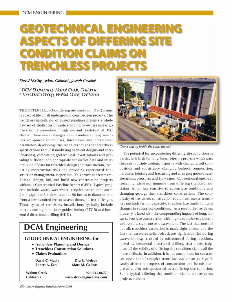
THE POTENTIAL FOR differing site condition (DSC) claimsis a fact of life on all underground construction projects. Thetrenchless installation of buried pipelines presents a wholenew set of challenges of understanding to owners and engi-neers in the prevention, mitigation and resolution of DSCclaims. These new challenges include understanding trench-less equipment capabilities, limitations and operationalparameters, developing true trenchless designs and trenchlessspecifications (not just modifying open-cut designs and spec-ifications), completing geotechnical investigations and pro-viding sufficient and appropriate subsurface data and inter-pretation of data for trenchless design and construction, eval-uating construction risks and providing experienced con-struction management/inspection. This article addresses tra-ditional design, bid, and build new construction projectswithout a Geotechnical Baseline Report (GBR). Typical proj-ects include water, wastewater, recycled water and stormdrain pipelines 6 inches to about 96 inches in diameter andfrom a few hundred feet to several thousand feet in length.These types of trenchless installations typically includemicrotunneling, pilot tube guided boring (PTGB) and hori-zontal directional drilling (HDD).
The potential for encountering differing site conditions isparticularly high for long, linear pipeline projects which passthrough multiple geologic deposits with changing soil com-position and consistency, changing bedrock composition,hardness, jointing and fracturing and changing groundwaterelevations, pressures and flow rates. Conventional open-cuttrenching, while not immune from differing site conditionclaims, is far less sensitive to subsurface conditions andchanging geology than trenchless construction. The com-plexity of trenchless construction equipment makes trench-less methods far more sensitive to subsurface conditions andchanges in subsurface conditions. As a result, the trenchlessindustry is faced with the compounding impacts of long, lin-ear subsurface construction with highly complex equipmentand remote, sight-unseen, excavation. The fact that most, ifnot all, trenchless excavation is made sight unseen and thefact that excavated soils/bedrock are highly modified duringexcavation (e.g., crushed by microtunnel boring machines,mixed by horizontal directional drilling, etc.) makes judg-ment of the validity of differing site condition claims all themore difficult. In addition, it is not uncommon for contrac-tor operation of complex trenchless equipment to signifi-cantly affect the progress of construction and be misinter-preted and/or misrepresented as a differing site condition.Some typical differing site condition claims on trenchlessprojects include:
David Mathy1, Marc Gelinas1, Joseph Covello2
1 DCM Engineering, Walnut Creek, California2 The Covello Group, Walnut Creek, California
GEOTECHNICAL ENGINEERINGASPECTS OF DIFFERING SITECONDITION CLAIMS ONTRENCHLESS PROJECTS
26 Western Regional Trenchless Review 2008
“Don’t end up inside the court house”.
• Obstructions• Low production rates• Excessive cutter face/tooling wear• Deviation from line and grade• Excessively high jacking/pull back forces• Ground surface heave or settlement• Undermining and damaging existing utilities • Fluids hydrofracture and fluids loss• Settlement and inability to steer• Cracked or damaged pipe
Some of these conditions can be fatal to the process andcause abandonment of the trenchless method. Almost all ofthese claim sources are unique to trenchless construction andwill not typically be found in traditional open-cut trenching.Most importantly, the majority of these potential claimsources can be caused by natural or manmade subsurfaceconditions or by contractor operations.
One of the most consistent themes in trenchless technolo-gy literature over the past 15 years in the United States is theimportance of geotechnical information upon which to baseboth owner design and contractor selection of trenchlessequipment and equipment options (i.e., match equipment tothe ground). Just as trenchless equipment is far more com-plex than open-cut trenching equipment, and just as trench-less equipment is far more sensitive to subsurface conditionsand less forgiving to changes in subsurface conditions, theneed for geotechnical information and geotechnical interpre-tation is greater for trenchless projects. Unfortunately, manyowners and design engineers don’t yet recognize this fact andspecify the same geotechnical investigation that has beenused for years for open-cut trenching projects. A typical geot-echnical investigation for open-cut trenching will not be ableto identify the many and diverse risk factors for trenchlessconstruction. A geotechnical investigation for trenchlessprojects should include the following phases:
Phase 1 – Establish alignment geologic setting and devel-opment history through geologic research, reconnaissanceand field mapping of geomorphic and development featuresand research into private and public sector developmentalong the alignment. It is imperative to establish geologic set-ting to allow for planning the subsurface geotechnical inves-tigation and interpret/interpolate between and beyond testboring locations. It is equally important to establish align-ment development history to check for potential obstruc-tions (e.g., fill debris, basement tie-backs, remnant pile foun-dations, contamination, etc.). This research can be donethrough historic maps, historic aerial photographs, local gov-ernment agency records (e.g., city, county, state), local historicsocieties and environmental regulatory agency records. Phase1 should also include research into construction precedence
(i.e., similar trenchless construction in the vicinity of the proj-
ect in the same geologic formations).
Phase 2 – Preliminary subsurface investigation including
borings, test pits and/or large diameter borings (to examine
fill debris, oversize material, cobbles and boulders, etc.), cone
penetration tests and geophysical testing all widely spaced
along the alignment. The results of Phase 1 and 2 will allow
for project alignment commitment, design of shaft spacing
for microtunneling and PTGB and bore path profile design
for HDD.
Phase 3 – Final subsurface investigation including test
Western Regional Trenchless Review 2008 27
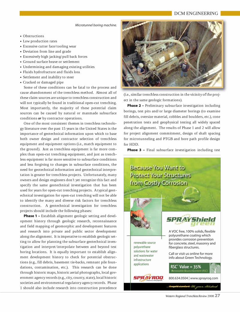
Microtunnel boring machine.
DCM ENGINEERING

borings at all shafts, mid-drive borings,(when shaft spacing exceeds about 500feet), large diameter borings, test pits,cone penetration tests, geophysicaltesting and groundwater monitoringwells. The results of Phase 3 (combinedwith Phase 1 and 2) will provide tunnelzone and bore path specific soil,bedrock and groundwater conditionsand engineering properties.
The importance of research intoalignment development history cannotbe overstated. In most urban settings,there will be a wealth of subsurfaceinformation potentially covering mul-tiple generations of development.Research should include “abandoned”or demolished facilities to ensure thatthe alignment is not close to remnantfoundations, etc.
Historically, geotechnical reports forunderground pipe lines to be installedby open-cut trenching are completed ata very early stage of design and withminimal coordination with the finalproject plans and specifications. Inaddition, these reports often do not doa good job of separating findings fromconclusions and recommendations.Some of the conclusions and recom-
mendations of these reports may notapply to the final design. As a result,owners have become reluctant toinclude geotechnical reports in thecontract documents for fear of havinginconsistencies with the final plans andspecifications and having those incon-sistencies used against them in a DSCclaim. For trenchless projects, it is use-
ful to follow the major undergroundconstruction and tunneling model anddivide the geotechnical investigationinto the following two parts:
Part 1 – Geotechnical Data ReportPart 2 – Geotechnical Design Sum -
mary Report (sometimes referred to asGeotechnical Interpretive Report orGeo tech ni cal Memoranda for Design)
The Geotechnical Data Report(GDR) should contain all of the objec-tive data generated by the geotechnicalinvestigation (e.g., research results, geo-logic mapping, boring logs, lab tests,CPT logs, geophysical plots, etc.). Thegeotechnical data can then be provideddirectly to bidding contractors in thecontract documents. The GeotechnicalDesign Summary Report (GDSR)should contain the geotechnical engi-neer’s interpretation of the geotechni-cal data including interpolated subsur-face soil profiles within the context ofoverall geologic setting and develop-ment history, and specific recommen-dations for trenchless design and con-
28 Western Regional Trenchless Review 2008
DCM ENGINEERING
At right: Slurry separation plant.Below: Tunnel cuttings from a microtunnel
boring machine througha slurry separation plant.

Western Regional Trenchless Review 2008 29
DCM ENGINEERING
struction. The GDSR report should becarefully coordinated with the finalproject plans and specifications. In themajor underground construction andtunneling model, these reports are fol-lowed by a Geotechnical BaselineReport (GBR) in which subsurfacequantities (e.g., groundwater, boulders,fill debris and obstructions) are quanti-fied for contract and bidding purposes.
The topic of DSC claims on trench-less projects is much too big for an arti-cle of this size. The principal objectivehere is to reinforce with owners andengineers that trenchless designs andthe evaluation of DSC claims ontrenchless projects is much more com-
plicated and demanding than conven-tional open-cut trenching. In addition,there is much more pressure to resolvea DSC claim and keep the project mov-ing forward because of the contractor’scommitment of very expensive equip-ment and personnel. For the mostpart, this equipment cannot be easilyand quickly demobilized, particularlywhen compared to an open-cut excava-tor. It is in no one’s interest to incurstandby charges for idle trenchlessequipment and specially trained opera-tors, which in the case of microtunnel-ing, can amount to as much as $1,000per hour for equipment only, pluslabor costs of a typical six man crew.
(Combined equipment and labor
standby can be as much as $15,000 per
day for microtunneling.) While the
potential for differing site condition
claims will never be eliminated, it can
be reduced and the resolution can be
quickened to the benefit of owners and
contractors by:
• an experienced design team;
• thorough alignment research looking
into development history;
• thorough research into, and incorpo-
ration of, construction precedence in
the project vicinity in the same geo-
logic deposits;
• thorough and accurate geotechnical
investigations specifically tailored to
the trenchless method;
• experienced interpretation of geot-
echnical data in the context of geo-
logic setting site history and trench-
less methods of construction;
• detailed plans and specifications
written specifically for the trenchless
method to be used; and
• experienced construction manage-
ment working with the contractor to
complete a successful project. ❍
At left: Tunnel cuttings from HDD.Above: “Sticky” clays plugging the face ofa microtunnel boring machine.

CITY OF LOS ANGELES
I. Introduction In October 2004, the City of Los Angeles Department of
Public Works (DPW) reached a settlement agreementwith various governmental and environmental agen-cies to rehabilitate and replace old, damaged, andsubstandard sewer pipes throughout the City for thenext 10 years. This work will be done by theSecondary Sewer Renewal Program (SSRP). The sewerpipes in this program are small – less than 16 inches indiameter – but are important because they are connect-ed to residents’ and businesses’ private sewers. There areapproximately 6,500 miles of them which serve more thanfour million people in the San Fernando Valley, West LA,Central LA, and Harbor areas (Figure 1). The smaller sewersconvey the waste stream to larger sewers that carry waste-water to the Hyperion Treatment Plant in Playa del Rey whereit is treated to a high quality before being released into theSanta Monica Bay. Rehabilitation of the faulty sewer pipeswill improve sewer flow, reduce maintenance and potentialsewer spills, and help minimize sewer odors. In order to meetthe requirements and deliver the increased number of proj-ects in a timely manner, sewers are being renewed by R&R(Remove & Replace) or lining at an average rate of 60 milesper year. The SSRP is commonly referred to as the 60-MileProgram. Since this program started in 2005, the work com-pleted has exceeded the annual 60 mile/year schedule. TheGIS-based program SMARTS© (Sewer Management Auto -mated Repair Tracking System) is dedicated to planning,designing, constructing, and managing the wastewater net-work in the City of LA.
II. SMARTS© Induced Sewer Management SMARTS© is a system of customized tools developed in
ARCGIS to help engineers design for the secondary sewerrenewal. It has been developed by GIS consulting companies(MARRS Services in the development stage, and currently bySuper GIS, Inc.) and the SSRP group. It offers a unique blendof capabilities in secondary sewer management and repair
design.The systememploys GIStechnology to usethe up-to-date geo-graphic informationand sewer pipe surveyinformation to deliverdesign projects faster, moreaccurately, more efficiently, andmore cost- effectively.
As presented in Figure 2., byusing GIS and database technolo-gy, SMARTS© integrates a largeamount of both spatial and non-spatial information into the GIS sys-tem. This program helps design engi-neers analyze the location and all important characteristics ofdamaged pipes, resulting in the best design for the piperepairs and sewer management. SMARTS© provides SSRPengineers all the necessary information relating to sewermains, sewer maintenance holes, sewer laterals, and othersewer related facilities fund CCTVs. This information is thenrendered on top of the City base map Parcels, streets, free-
By Keith Hanks, Richard Pedrozo, Mina Azarnia, Yafan Su, and Daeik Kim
INNOVATIVE METHOD TOMANAGE AND REPAIR THESEWER THE SMARTS© WAY
30 Western Regional Trenchless Review 2008
Figure 1.SSRP Basin Plan and Projects

Western Regional Trenchless Review 2008 31
ways, and easements to show the location of the damagedpipe on the map. More maps (House connection vector data,easement data, Thomas map grid, Council boundary, etc.)and color aerial photos have been added into SMARTS©recently. In addition to this, SMARTS© incorporates otherinformation that will help SSRP engineers identify factorsrelating to sewer repair. This includes but is not limited tostorm drains, substructure utilities, and aerial photographimages.
Below are the major feature/functionalities of SMARTS©.• Quick search of the pipe and its location• Identify/highlight pipes that need repair• Incorporate CCTV log information and pipe condition
information to identify damaged segments• Incorporate CCTV videos of the sewer pipe, which will
enable engineers to review the CCTV just by clicking thepipe
• Spatially identify sewer laterals/WYE along the reach• Provide initial repair approach based on SSRP guidelines.
In the design methods, structural lining is added in addi-tion to original non-structural lining and R&R. RecentlyBlind or capped WYE identification has been added toSMARTS©.
• Add/Remove repair segment of the pipe• Spatially identify neighboring utilities’ orientation and
station• Input and store the design data into the database• Generate “Vicinity Map”, “Index Map”, “Key Map” and
“Construction Map” for the project. The repair designmaps can be referenced and color-coded to represent dif-ferent repair methods so the construction engineers cansee the design on the maps. (See Figure 3)
• Generate various reports (Schedule of Repairs, Pre-Designand initial Cost “C” Estimates etc.) for the project. Morereports (e.g. Field Investigation Checklist, Class “A” Cost
Estimate, 60-Mile Project Tracking and StreetCategory, etc.) have been added into SMARTS©and can be auto-generated by SMARTS©.
Overall, SMARTS© allows users to review pipecondition assessments, construction constraints(utilities, site conditions, etc.), verify pipe informa-tion, help engineers to do the design, input andmanage design data, and print design documentsand various maps. The system continues to bedeveloped as the new design procedures and func-tions are suggested by the engineers and needed forthe SSRP group.
III. Recent and On-Going Progress of SSRP Recently, the City of LA endowed the DPW with a
“Technological Innovative Award,” for the SMARTS programused by SSRP. It was also presented at the 2008 WEFTEC(Water Environment Federation Technical Exhibition andConference) in San Diego. The SSRP, using the SMARTS pro-gram, received attention from both private and governmentalsectors. A protocol has been set up to expedite the delivery ofthese projects. As part of this process, the City subdivided theentire project area into 210 sewersheds, as shown in theFigure 1. In the sewersheds, more than 100 projects are iden-tified. Among them, twenty five projects have been success-fully completed by 12 city engineers and 5 consulting engi-neers in terms of project design. Engineers in the SSRP designteam have a wide range of work experience, from 32 years torecent graduates. The current design group includes 1 SeniorCivil Engineer, 2 Civil Engineers, 6 Civil Engineer AssociatesII and IIIs, 5 Consultants, and 6 Civil Engineer Associate Inew employees. For the Fiscal Year 2007/08, an average ofeight contractors bid on SSRP projects. For the Fiscal Year2008/09, designs for 60.57 miles were finished and designsfor an additional 12.32 miles were already completed for theFiscal Year 2009/10. Some of these projects are under con-struction by the bid-won contractor, based on the designpackage. The revised design package form includes: projectmaps (vicinity, index, key maps), schedule of repair, cost esti-mate, SSRP general requirement (GR), general conditionsand technical specifications, and is packaged in an 8 ½” x 11”letter size format.
Given the delivery goal of 60 miles designed annually, theBureau of Engineering (BOE) created a standardized designmanual in which all viable rehabilitation methods and designguidelines are described in detail: for instance, the R&R meth-ods and lining are explained. The design manual conforms toa well-defined regimen. The defects of pipes are categorizedto root intrusion/blockage (light, medium, severe), various
CITY OF LOS ANGELES
Figure2. Pathway of SMARTS© Program

32 Western Regional Trenchless Review 2008
structural upgrades such as new main-
tenance hole installation, remodeling
of maintenance hole base, chimney
replacement, drop connection, lamp-
hole replacement, flush tank replace-
ment, etc. Three rehabilitation meth-
ods are feasibly applied: remove and
replace (R&R), lining, or a combina-
tion of these two. The lining material
can be any of the City’s approved prod-
ucts for structural or nonstructural lin-
ing. When there is more than one
option to repair a reach, a cost-benefit
analysis is performed to find the most
economical solution. Additional fac-
tors such as traffic conditions will also
have impact on the selection of repair
method. When it comes to the method
selection, the sewer design is per-
formed with the goal of minimizing
the inconvenience to residents and
providing the best quality of sewer
work. The design manual and maps are
continually updated due to the innova-
tive ap proach of repair methods and
redefined repair items. Figure 3 illus-
trates an improvement in the construc-
tion map where different repair meth-
ods such as R&R, lining, and structur-
al lining, are shown. ❍
CITY OF LOS ANGELES
OUTSIDE SALESREPRESENTATIVES
Dynamic national company specializing in pump, pipe, tank, and filtration rental sales andservice is seeking an Outside Sales Rep with strong sales skills in Ventura, Los Angeles,Riverside, Orange County and the South Bay area. Hiring for ability and will train. Pump, fil-tration, water treatment or rental experience a plus but not required. BA/BS degree or equiv-alent needed. Must be motivated and possess good communication, PC and math skills.Excellent compensation and benefit package. To join a growing and team oriented company,send your resume to:
Human Resources Ref: RFROSRain for Rent
Fax: (661) 391-3565www.rainforrent.com
All applicants must submit to a pre-employmentbackground check, drug screen and physical.
EEO/AA Emp. M/F/V/D
Figure3. Improved Construction Map

APOLLO TRENCHLESS
IT SHOULD BE no big secret that one of the fastest growingsegments of trenchless technologies today are the municipalmarkets. With so many different ways to approach a project,engineers are faced with the daunting task of not only under-standing all the different types of trenchless technologies avail-able to them (HDD, pipe bursting, sliplining, etc.) but they arealso expected to know how to effectively select the most appro-priate technology for the project at hand. In addition, as thesetechnologies continue to improve, the challenge of providingproject owners with effective trenchless solutions continues tobecome more complex. For those who find themselves in thissituation, and lacking the ability to become an expert with allthe different trenchless options available today, it may be moreadvantageous to focus on the few technologies that can offerthe most “bang for your buck”. One such technology has beenthe process of installing Ductile Iron Pipe utilizing HorizontalDirectional Drilling (HDD).
Many municipal owners and operators have chosen DuctileIron Pipe as the preferred material with which to build theirinfrastructure. While many of these people see a great oppor-tunity for trenchless installations of their pipelines, they areoften left with the misconception that HDD can only be usedto install plastic or steel pipe. Nothing could be further fromthe truth. With the use of a Restrained Joint Ductile Iron Pipe,entire water transmission and distribution systems have beenconstructed exclusively through the use of HDD.
From the owner’s perspective, the use of HDD can offer sev-eral advantages to a trenchless pipeline installation. HDDinstallations often result in significantly less disturbance to thepublic throughout the project, less social costs, and manytimes can even be faster and cheaper when compared to tradi-tional construction methods. Installation of ductile iron pipewill also allow municipalities to utilize a material that is famil-iar and will not create the maintenance issues that result fromhaving various types of pipe materials in one system. Some ofthe advantages specific to Ductile Iron Pipe are its ability tohandle higher pressures and structural loads than plastic pipes,the ability to locate the pipe without needing a tracer wire, andthe corrosion protection obtained by installing the pipe with apolyethylene wrap and/or cathodic protection.
From an HDD contractors perspective, pulling ductile ironcan often times be easier than pulling a steel pipe, because arestrained joint ductile iron pipe allows a generous amount ofdeflection at each of the joints, which in turn allows a drilledbending radius that would not be possible with steel pipeinstallation. Another advantage to drilling with Ductile IronPipe is the ability to use the cartridge method of installation.When pulling steel or plastic, it is often necessary to preassem-ble the pipe prior to the pullback so that the borehole does not
collapse within the time it takes to fuse or weld sections ofpipeline. When using the cartridge method with Ductile IronPipe, the joints can be assembled in such a short amount oftime that the pullback phase and assembly of the pipe stringcan occur at the same time. This reduces or even eliminates theneed for large staging areas to preassemble pipe.
In today’s environment of increasing performance standardsand decreasing budgets, we need to find ways of leveragingtechnology to keep up and maintain our infrastructure.Horizontal Directional Drilling has proven to be an effectiveinstallation method for Ductile Iron Pipe. Not only has it beenused in situations where roads and waterways need to becrossed, HDD has been used in situations where traditional cutand cover methods are appropriate, but a trenchless alternativeproved to be cheaper, quicker, or just plain cleaner.
If you should have further questions about the use of HDD to installDuctile Iron Pipe, please contact Aaron Cohen with Apollo Trenchless,Inc. at (480) 310-0734, or visit our website atwww.apollotrenchless.com. ❍
INSTALLING DUCTILE IRON PIPEUTILIZING HORIZONTALDIRECTIONAL DRILLING
Western Regional Trenchless Review 2008 33
HORIZONTAL DIRECTIONAL DRILLINGFOR WATER & SEWER INSTALLATIONS
Apollo Trenchless, Inc. is the trenchlessconstruction and engineering solution providerfor your infrastructure demands. With drill rigscapable of pipeline installations up to 48”diameter and single length crossings of up to3000 feet, we are the right choice for yourtrenchless project.
Trenchless installation services offered:• Restrained joint ductile iron• Restrained joint and fusable PVC• Preassembled HDPE and welded steel• Gravity flow sewers• Water/sewer services
2487 S. Gilbert Road #106-229, Gilbert, AZ 85296Phone: (480) 310-0734 • Cell: (630) 816-8791
www.apollotrenchless.com

TT TECHNOLOGIES
THE UTAH TRANSIT Authority(UTA) is working on final constructionof a 44-mile commuter based rail lineconnecting Salt Lake City with thecommunities to its north. While thetask of constructing these rail linesincludes many forms of above groundconstruction, trenchless technology isplaying a role as well. Claude H. NixConstruction/Jasco, Inc. (C.H. Nix),Ogden Utah, was contracted to com-plete a complicated series of casinginstallations under the rail line.
According to C.H. Nix ProjectManager Jon Nix, initially they werecalled in to assist Commuter RailConstructors with the preliminarybudget numbers for the project, but didnot get the bid when the project wasawarded. However, the original borecontractor had been on the project forabout four months when they wereasked to leave, and Nix was called in onan emergency basis.
C.H. Nix needed to rescue an augerbore with a 60-inch steel casing thatwas stuck 40 feet into an 80-foot stormdrain bore. The auger had created avoid and subsequent 15-foot diametersinkhole between two Union Pacifictracks. C.H. Nix brought in an 18-inchGrundoram Goliath pipe rammer from
trenchless equipment manufacturerTT Technologies, Aurora, Ill. to com-plete the bore. Once ground waterissues were under control and the pitset up, crews were able to complete theram in short order.
In addition, a second 60-inch bore atthe location had also been started andnot completed. According to Nix, thesecond casing had been sitting at the 60-foot mark for over three months. Even
though the casing had sat idle in theground for several months, the Nix crewwas able to break the casing free with theGoliath rammer and ram the casing anadditional 20 LF to complete the align-ment. From there, CNC became an inte-gral part of the project, as did pneumat-ic pipe ramming.
Ramming Basics & BenefitsTrenchless pipe installation through
ramming is a fairly simple process. Apneumatic hammer is attached to therear of the casing or pipe. The rammingtool drives the pipe through the groundwith repeated percussive blows.
According to TT Technologies piperamming specialist Jim Moore, severaloptions are available for ramming vari-ous lengths of pipe. He said, “An entirelength of pipe can be installed at onceor, for longer runs, one section at a timecan be installed. In that case, the ram-ming tool is removed after each sectionis in place and a new section is weldedon to the end of the newly installed sec-tion. The ramming tool is connected tothe new section and ramming contin-ues. Depending on the size of the instal-
PIPE RAMMING FOR UTA:CLAUDE H. NIX CONSTRUCTION
The C.H. Nix ramming project was completed for a commuter rail line involvingconstruction of approximately 45 miles of new track, running from North Ogden,Utah to Salt Lake City, Utah.
Pipe ramming is a favorite installation method for contractors installing casings underroads and rail lines because the method provides accurate installation in a wide range ofsoils without surface slump.
34 Western Regional Trenchless Review 2008

Western Regional Trenchless Review 2008 35
TT TECHNOLOGIES
Above left: C.H. Nix crews used a Grundoram Goliath pneumatic pipe rammerfrom TT Technologies to install numerous casings at different locations along
the new rail line. Top right: In several situations the C.H. Nix crew used theGrundoram Goliath in conjunction with a pilot tube boring machine to
complete the casing installations. Note the ramming adapter attached to thelead end of the casing. At right: Casing diameters on the project ranged from
20 inches all the way up to 60 inches. Lengths ranged from 140 feet to 225 feet.
lation, spoil from inside the casing canbe removed with compressed air, water,an auguring system or other types ofearthmoving equipment.”
Some casing installation methods areimpaired or even rendered inoperableby rock or boulder filled soils. Pipe ram-ming is different. During pipe ram-ming, boulders and rocks as large as thecasing itself can be "swallowed up" asthe casing moves through the soil andcan be removed after the installation iscomplete.
Ramming tools, in general, are capableof installing 4- through 147-inch diame-ter pipe and steel casings. Rammingrequires minimal working depths andhas proven effective for horizontal, verti-cal, and angled applications. Ramming isalso ideal for installations under roadsand rail lines because it displaces the soilwithout creating voids or slumps.
Multiple RamsAfter freeing and installing the stuck
60-inch casing the crew moved on to thenext project site (3rd and 4th crossings)for another storm drain installation. Itincluded two parallel 48-inch steel cas-ings. Difficulties on this site includedminimal cover over the casing, less than18 inches below tracks, very limitedmuddy access, and proximity to the rail-road tracks.
The third site (5th crossing) was themost difficult. The scope of work includ-
ed boring under three sets of tracks andinto an existing freeway embankment inorder to realign an existing pressure irri-gation water line. The owner wanted toencase the line in one continuous steelcasing across both the freeway and rail-road tracks. The existing irrigation linehad a horizontal bend in it that neededto be removed and re-aligned.
Prior to construction, no one knewwhere the end of the existing casing forthe irrigation line was located or exactlyhow deep it was. Nix knew that oncethey located the existing end of casing,that accuracy in order to line up andbore to the existing end from the oppo-site side of the tracks would be critical.C.H. Nix crews opted to use anAkkerman pilot tube guided boring sys-tem and Goliath pipe rammer to com-plete this drive.
C.H. Nix crews were able to push thepilot tubes, and ram the 36-inch casing200 lf across the tracks with less than a2-inch deviation between the existingcasing and the newly installed casing.The crews were also able to connect thetwo by splitting and rewelding a piece of36-inch casing. Construction alsoincluded the installation of 30-inchHDPE through the steel casing.
The 6th through the 9th crossingswere completed in the Ogden Rail Yard.
A 24-inch steel casing, for stormdrain, was rammed 200 linear feetacross seven sets of tracks. The pilot
tube system was also used on this drivefor line and grade accuracy.
The 8th and 9th crossings were paral-lel 60-inch steel casings, for re-align-ment of an existing storm drain box cul-vert. C.H. Nix crews completed both ofthese crossings using an AkkermanTBM and series 5000 pipe jacking sys-tem. Nix used this method because ofthe pipe size, minimal grade, and tightalignment. They were able to come inon design line and grade with less than0.05 feet of deviation.
The 10th crossing included theinstallation of a 36-inch storm drainculvert crossing. It was similar to theothers with minimal cover, poor soilconditions, and high ground water.C.H. Nix crews were able to completethe crossing successfully using piperamming.
The 11th crossing was completed fora water transmission re-alignment andincluded ramming 120 lf of 36-inch cas-ing, and the sliding a 30-inch HDPEthrough the casing. Then crewsinstalled a 16-inch ductile iron pipe oneither side of the tracks and connectedit to the 30-inch HDPE.
The final three crossings (12ththrough 14th) will be constructed indowntown Salt Lake City. They willconsist of three 24-inch bores. All threecrossings will be completed using pilottube technology and the Goliath piperammer. ❍

36 Western Regional Trenchless Review 2008
A NEW WATER intake facility on the Sacramento River will supplement ground-
water and existing water conservation programs to the Sacra mento County and
East Bay area of California for many years to come. Mining 30’ below the water
table requires expertise. Microtunneling, often referred to as remote controlled
pipejacking, is the best application for unstable ground conditions. In the spring
of 2008, subcontractor Water C. Smith successfully installed 829’ of 102” steel cas-
ing under I-5 in Sacramento, just east of the intake facility with Akkerman micro-
tunneling equipment.
The Freeport Regional Water Intake Facilities job, owned by the Freeport
Regional Water Authority, will provide up to 185 mgd of drinking water to an esti-
mated 2.5 million customers. The scope of the project includes several pipeline seg-
ments and a water surface treatment plant. The contractor is Balfour/Beatty.
AKKERMAN MICROTUNNELINGEQUIPMENT PROMINENTIN SACRAMENTO By Laura Anderson
AKKERMAN

Pipelines will provide Sacramento County
residents with supplemental groundwater
and East Bay residents with water during
dry periods. The $903 million costs were
split between the two communities. The
construction portion of this project
began in December 2006 and will contin-
ue through 2011. The Freeport Regional
Intake Facility, located on the Sacramento
River, will feature a landscaped buffer and
art and poetry wall to help with aesthetics
for adjacent homes.
Walter C. Smith’s work consisted of two
drives, the first 487’ drive under I-5 and
the second 342’ drive under Freeport
Boulevard. A few years earlier, an attempt-
ed drive by a different contractor near the same area as the
first drive was conducted via microtunneling, and failed due
to the varied, wet ground conditions. Con se quent ly, Walter C.
Smith had some justified apprehension when ap proaching
this drive, as well as concerns about the larger sized
Microtunneling Boring Machine (MTBM) and drive length in
this type of soil.
The launch shaft needed to be 65’ deep with the ability to
withstand the high water head and an estimated 1,400 tons of
jacking force for pipeline advancement. Both the launch and
reception shafts were designed with grout concrete in front of
the pit seal and applied to the entrance and exit portals to
properly hold back the high water head.
Superior MTBM operation was essential to avoid any
ground subsidence. Walter C. Smith operators encountered
some challenges with the constant monitor and control of
water pressures. They found that the MTBM performed best
when the microtunneling slurry pressure was adjusted to
counterbalance the ground water pressure and in turn,
decrease jacking forces.
Walter C. Smith used an Akkerman MTBM SL74 with an
increase kit to 102” and control container, Westfailia jacking
frame and custom separation plant. Despite their initial
uneasiness, operators reported that all components per-
formed well with very little down time.
Construction on the Freeport Regional Water Intake
Facilities job will continue through 2011 and commence
with the construction of the Vineyard Surface Water
Treatment Plant.
Laura Anderson is a marketing specialist for Earth Pressure Balance,
Guided Boring Machine, Microtunneling, Tunneling and
Pipejacking equipment manufacturer, Akkerman Inc. of
Brownsdale, MN. ❍
Akkerman MTBM SL74 into 65’ launch shaftnear Freeport Regional Water Intake Facility in
Sacramento.
AKKERMAN
Western Regional Trenchless Review 2008 37

SPECIALIZED SERVICES CO.
Introduction:Saint Croix is an island in the
Caribbean Sea, and a county and con-stituent district of the United StatesVirgin Islands (USVI), an unincorporat-ed territory of the United States. It is thelargest of the U.S. Virgin Islands, being28 by 7 miles (45 by 11 km) and hostsone of the world’s largest and mostmodern oil refineries.
Construction of the 45,000 barrelsper day (BPD) refinery began in Octoberof 1966. Substantial expansion occurredin the period 1966 to 1974 to increasethe refinery's capacity and making it thelargest refinery in the world at that time:Heavy oil upgrading capacity was gradu-ally added beginning in 1981, eventuallyincreasing the refinery's capacity to485,000 barrels per day BPD.
To accommodate the original 2,000+
acre facilities on the south shore of St.Croix, a ¼ mile of wetlands was dredgedand contained by a 120’ long x 20’ highdike that eventually became home to aservice road, power and fire lines, andfour major fuel lines that connected therefinery to adjacent holding tanks.
Many years and four major hurricaneslater, two of four fuel lines had to beshut down due to leaks. At a cost of$800,000 per day in lost revenue, imme-diate upgrades were required.
Design ConsiderationsLack of as-builts and supporting doc-
umentation for the original facility andcontainment areas proved an immediatechallenge. Although it was well knownthat a 30” fire line, a 12” water line, anda 12,000 KV electric line existed in thearea of the newly proposed pipelines,
their exact location and depth wasunknown. Initial soil investigationrevealed moderate clay and coral at 15-ft., however soil conditions beyond thatpoint were also unknown.
To minimize the cost and risks associ-ated with this project, horizontal augerbore was selected as the most suitablemethod. Four 120’ auger bores to install(2) 30” OD steel casings and (2) 48” ODsteel casings were required.
Installation ChallengesConstruction began in early October
2007. The first of the two bores toinstall 48” OD steel casing failed.Extreme weather had stripped the bind-ing material from the outer layer ofcoral, causing the loose material it tocave in. Dropping a foot below grade, asecond bore successfully cleared theloose material, but became bound indense sticky clay at approximately 60ft.Water was pumped in and around theauger to loosen the clay and allow theauger to glide for another 40 ft. Onceagain, the auger encountered the outerlayer of coral as it exited the dike, mak-ing turning the auger impractical. It wasthen shut down and used as a rammingdevice for the remaining 20 ft., success-fully avoiding an overflow oil drain thatwas discovered during the installation.
With little room to maneuver, and lit-tle time to spare, each of the threeremaining casings were installed suc-cessfully and the project was completedin mid October 2007, amazingly eightdays ahead of schedule.
Although the lack of as-builts did
By Arvid Veidmark, III , Owner/Senior Estimator, Specialized Services Company (SSC)
38 Western Regional Trenchless Review 2008
LACK OF AS-BUILTSCAUSE A STICKYSITUATION IN ST. CROIX
Aging pipelines.

Western Regional Trenchless Review 2008 39
SPECIALIZED SERVICES CO.
Above left: New fuel lines.Above right: Loose coral causes challenges.
prove detrimental initially, we were ableto employ a combination of innovation,technology, and experience that resultedin success.
As demonstrated on this project, thelack of as-builts and documentation willbe the initial hurdle for any project. Anexcellent set of as-builts can save much
time and money for an owner and con-
tractor, helping them to make more
informed decisions and reduce risk. It is
common for changes to be made during
construction. What becomes the chal-
lenge is making sure those changes are
reflected in the as-built records.
Arvid Veidmark, III has more than two
decades of operational experience and holds
multiple licenses and certifications. He has
sponsored over 50 educational seminars and
has been consulting on major City improve-
ment projects in the Phoenix metropolitan
area since 1997. ❍

40 Western Regional Trenchless Review 2008
AUI INC.
IN 2006, THE City of Phoenix beganthe Sanitary Sewer Relief andReplacement Program to increase thecapacity of city sewer lines to combatsanitary sewer overflows and providefor future development. The areasrequiring increased capacity were deter-mined by the city’s Water ServicesDepartment and arranged into a seriesof projects by priority. Sundt/AUI, AJoint Venture was awarded PriorityProject No. 13 titled “Basin K01Maryland Avenue – N. 33rd Avenue toN. 27th Avenue”. The scope of work forthis project included installation ofapproximately 4,000 LF of 10” through15” VCP sewer lines using open-cut-and-replace construction, installationof 3,200 LF of 14” and 18” HDPE sewerlines using pipe bursting, sewer dewa-
tering and by-pass pumping, rehabilita-tion of existing sewer manholes, con-struction of new sewer manholes,removal and replacement of existingasphalt, curb and gutter, sidewalk andlandscaping, and abandonment ofexisting sewer lines. As part of the jointventure team, AUI Inc. (AUI) providedthe services of their TrenchlessTechnology Division to complete thepipe bursting portion of the scope ofwork.
Background – In 1998, AUI com-pleted a pipe bursting pilot project forthe City of Phoenix. This pilot projectincluded replacement of 521 LF of fail-ing sanitary sewer line with new 24”VCP using pipe bursting. The City ofPhoenix was tempted by advantages oftrenchless pipe replacement to reduce
replacement duration, minimize theduration by-pass pumping, minimizeor eliminate roadway closures and traf-fic control issues, minimize the poten-tial for damage to existing utilitiesthrough excavation, and reduce thecosts associated with surface restora-tion. Through this pilot project, AUIeffectively demonstrated to the cityrepresentatives that pipe burstingoffered a solution to the problem ofreplacing underground utility lines inhighly developed urban settings withminimal inconvenience to the inhabi-tants and without increasing construc-tion costs. Since that pilot project, theAUI pipe bursting team has completed110,000 feet of pipe bursting over 42separate projects.
The Phoenix Project – The 3,200 LFof pipe bursting included in this proj-ect was divided into three segmentsalong Bethany Home Road, MarylandAvenue and 27th Avenue. In July of2007, the AUI pipe bursting team,including Project Manager GaryHuffman and Project Super intendentArchie Lucero, mobilized to Phoenix tobegin the first segment on BethanyHome Road. This first segment wouldrequire three separate pulls to burst the919 feet of 10” VCP with 18” HDPE.AUI’s pipe bursting team subdividedthis segment into three pulls to mini-mize the risk of binding (specifically
— 919 LF Pipe Burst 10” Sewer Main with 18” HDPE — 2,320 LF Pipe Burst 10” Sewer Main with 14” HDPE
CITY OF PHOENIX SEWER LINE RELIEF & REPLACEMENT –
USING PIPE BURSTING IN APROJECT TO INCREASE CAPACITY
Ten inch existing clay pipe upsizedto 18 inch HDPE 17.

AUI INC.
when passing through the existingsewer manholes) due to the substantialincrease in pipe size, almost double thepipe size from 10 to 18 inches. The pipebursting team completed all three pullsin 26.5 hours and completely replacedthis segment of the sewer main inunder ten days (including sewer lateralreconnections and surface restoration).This segment included a burst directlyacross an arterial, signaled intersectionwith no lane drops; completely unde-tectable to the traveling public.
The second pipe bursting segmentof this project ran east alongMaryland Avenue for approximately1,345 feet. Although the pipe sizeincrease on this portion of the projectwas less than the previous pipe burstsegment, from 10 to 14 inches orabout 1.5 times, the team decided thatit would still be a good idea to dividethe segment into four separate pullsto (again) minimize the risk of bind-ing. The third segment of the projectwas 975 feet of 10 inch to 14 inchalong 27th Avenue.
Michael Rocco, AUI’s TrenchlessTechnology Division Manager and for-mer Chairperson of the InternationalPipe Bursting Association (IPBA),counts this project among the success-
es of the division and as a victory forpipe bursting technology in general.“Not only did we get to prove the pipebursting process is a solution to someof the common issues that cities have
with the open-cut-and-replace method,but we also made inroads for alterna-tive pipe materials in what has histor-ically been considered a clay pipemarket.” ❍
Western Regional Trenchless Review 2008 41
At left: AUI Sewer saddle fused to 14 inch HDPE.Above right:14 inch Bursting Head Assemblywith 14 Inch HDPE dr 17 pipe attached
12” WATERLINEPIPE BURSTING
PROJECT

42 Western Regional Trenchless Review 2008