Embed Size (px)
Citation preview
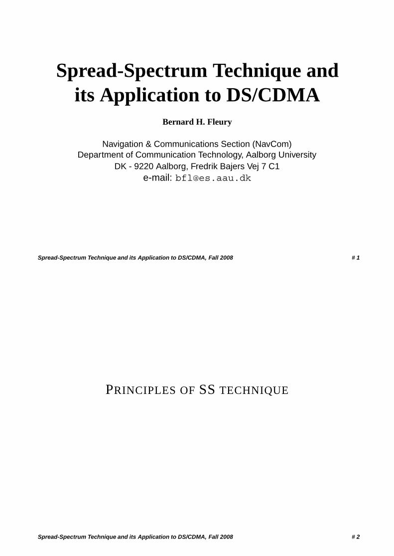
Spread-Spectrum Technique andits Application to DS/CDMA
Bernard H. Fleury
Navigation & Communications Section (NavCom)Department of Communication Technology, Aalborg University
DK - 9220 Aalborg, Fredrik Bajers Vej 7 C1e-mail: [email protected]
Spread-Spectrum Technique and its Application to DS/CDMA, Fall 2008 # 1
PRINCIPLES OF SS TECHNIQUE
Spread-Spectrum Technique and its Application to DS/CDMA, Fall 2008 # 2
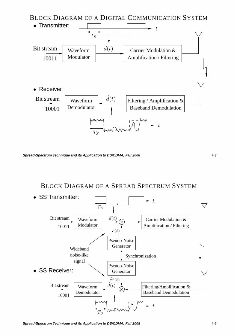
BLOCK DIAGRAM OF A DIGITAL COMMUNICATION SYSTEM• Transmitter:
Amplification / Filtering
Bit stream
10011
d(t)
t
WaveformModulator
Carrier Modulation &
TS
• Receiver:
Baseband Demodulation
Bit stream
10001
d(t)Waveform Filtering / Amplification &
t
Demodulator
TS
Spread-Spectrum Technique and its Application to DS/CDMA, Fall 2008 # 3
BLOCK DIAGRAM OF A SPREAD SPECTRUM SYSTEM
• SS Transmitter:
• SS Receiver:
Widebandnoise-like
signal
t
GeneratorPseudo-Noise
Bit stream
10011
d(t)
Pseudo-NoiseGenerator
Amplification / FilteringCarrier Modulation &
Filtering/Amplification &Baseband Demodulation
d(t)
10001
Bit stream
Synchronization
WaveformDemodulator
WaveformModulator
TS
tTS
c(t)
c∗(t)
Spread-Spectrum Technique and its Application to DS/CDMA, Fall 2008 # 4
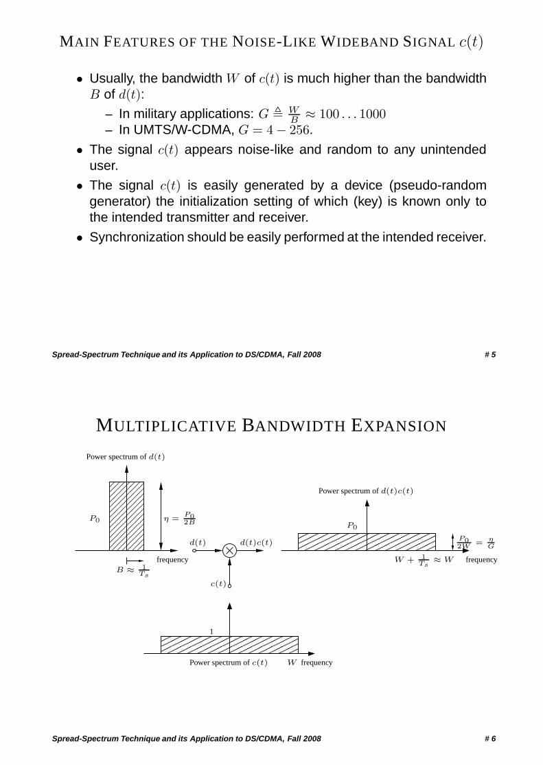
MAIN FEATURES OF THE NOISE-LIKE WIDEBAND SIGNAL c(t)
• Usually, the bandwidth W of c(t) is much higher than the bandwidthB of d(t):
– In military applications: G � WB ≈ 100 . . . 1000
– In UMTS/W-CDMA, G = 4 − 256.
• The signal c(t) appears noise-like and random to any unintendeduser.
• The signal c(t) is easily generated by a device (pseudo-randomgenerator) the initialization setting of which (key) is known only tothe intended transmitter and receiver.
• Synchronization should be easily performed at the intended receiver.
Spread-Spectrum Technique and its Application to DS/CDMA, Fall 2008 # 5
MULTIPLICATIVE BANDWIDTH EXPANSION
��������
��������
�����
�����
��������
����
��������������������������������
������
������
��������������������������������
������
������
����
P0
frequencyB ≈ 1
Ts
c(t)
d(t) d(t)c(t)
1
Power spectrum of c(t)
Power spectrum of d(t)
Power spectrum of d(t)c(t)
frequency
η =P02B P0
frequencyW + 1Ts
≈ W
P02W
= ηG
W
Spread-Spectrum Technique and its Application to DS/CDMA, Fall 2008 # 6
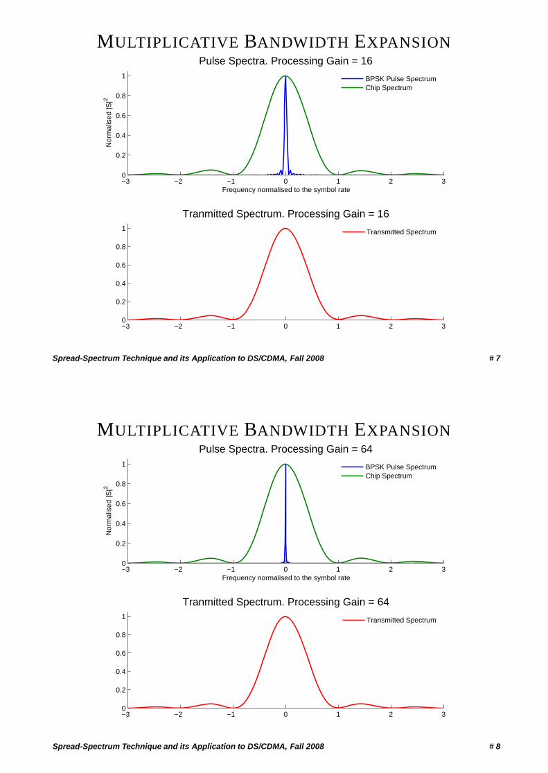
MULTIPLICATIVE BANDWIDTH EXPANSION
−3 −2 −1 0 1 2 30
0.2
0.4
0.6
0.8
1
Pulse Spectra. Processing Gain = 16
Frequency normalised to the symbol rate
Nor
mal
ised
|S|2
−3 −2 −1 0 1 2 30
0.2
0.4
0.6
0.8
1
Tranmitted Spectrum. Processing Gain = 16
BPSK Pulse SpectrumChip Spectrum
Transmitted Spectrum
Spread-Spectrum Technique and its Application to DS/CDMA, Fall 2008 # 7
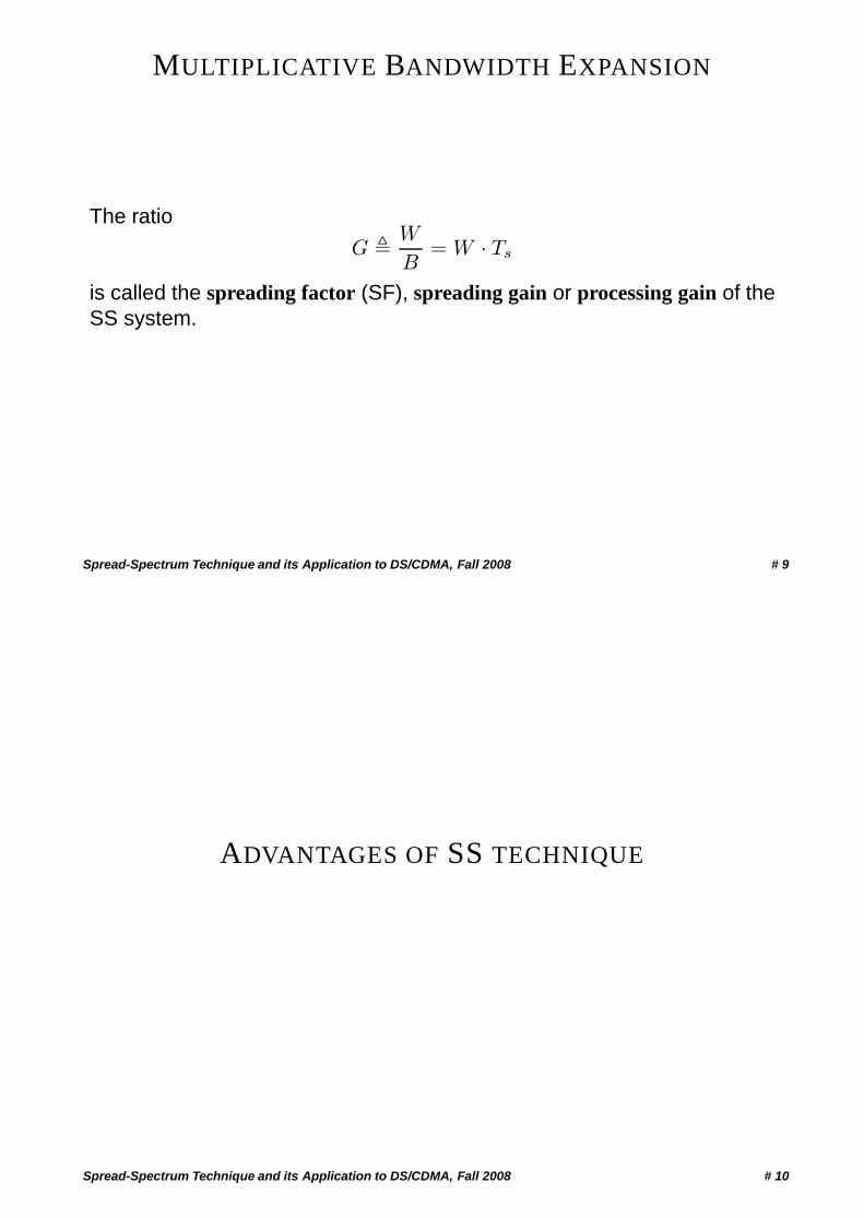
MULTIPLICATIVE BANDWIDTH EXPANSION
−3 −2 −1 0 1 2 30
0.2
0.4
0.6
0.8
1
Pulse Spectra. Processing Gain = 64
Frequency normalised to the symbol rate
Nor
mal
ised
|S|2
−3 −2 −1 0 1 2 30
0.2
0.4
0.6
0.8
1
Tranmitted Spectrum. Processing Gain = 64
BPSK Pulse SpectrumChip Spectrum
Transmitted Spectrum
Spread-Spectrum Technique and its Application to DS/CDMA, Fall 2008 # 8
MULTIPLICATIVE BANDWIDTH EXPANSION
The ratio
G � W
B= W · Ts
is called the spreading factor (SF), spreading gain or processing gain of theSS system.
Spread-Spectrum Technique and its Application to DS/CDMA, Fall 2008 # 9
ADVANTAGES OF SS TECHNIQUE
Spread-Spectrum Technique and its Application to DS/CDMA, Fall 2008 # 10
ADVANTAGES OF SS SYSTEMS
The following five items apply for large SF.1. Privacy.
It is a computational burden for an unintended user to demodulate aSS signal.
2. Low probability of intercept.Because of the low level of its power spectrum, a SS-signal can be“hidden” in the background noise.This feature makes a SS signal difficult to be detected by anunintended user.
3. High tolerance against interference.
• Intentional interference (jamming).• Unintentional interference (multiuser interference in a multiuser
communication system).
Spread-Spectrum Technique and its Application to DS/CDMA, Fall 2008 # 11
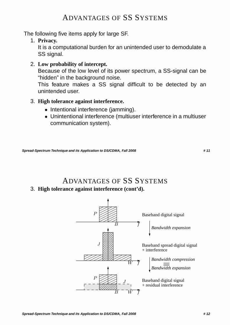
ADVANTAGES OF SS SYSTEMS3. High tolerance against interference (cont’d).
������������
������������������������������������
��������������������
������
������
��������������������������������������������
��������������������������������
����������������
������
������
������������
������������
����
���� �
��
���
����
����������������
P
P
Bandwidth expansion
Bandwidth compression
Bandwidth expansion
Baseband digital signal
Baseband spread digital signal+ interference
Baseband digital signal+ residual interference
J
B W f
W f
B f
J
Spread-Spectrum Technique and its Application to DS/CDMA, Fall 2008 # 12
ADVANTAGES OF SS SYSTEMS
3. High tolerance against interference (cont’d).
Signal-to-interference power ratio after bandwidth compression(also called de-spreading):
SIRd =P
J· G = SIRi · G
In dB:[SIRd]dB = [SIRi]dB + [G]dB
SIRi: Input signal-to-interference ratio.SIRd: Signal-to-interference ratio after despreading.
Interference reduction is proportional to the spreading factor G.
Spread-Spectrum Technique and its Application to DS/CDMA, Fall 2008 # 13
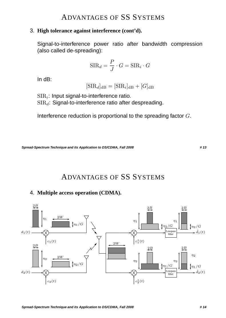
ADVANTAGES OF SS SYSTEMS
4. Multiple access operation (CDMA).
2B 2B
2B 2B
η2
2W
c2(t)
η2
η1/Gη2/G
Lowpassfilter
Lowpassfilter
η1
2W
2W
η2/G
2B
η1/G
2B
c1(t)
d1(t)
d2(t)
d1(t)
d2(t)
η2/G
η1/G
η1 η1
η2η2
c∗2(t)
c∗1(t)
Spread-Spectrum Technique and its Application to DS/CDMA, Fall 2008 # 14
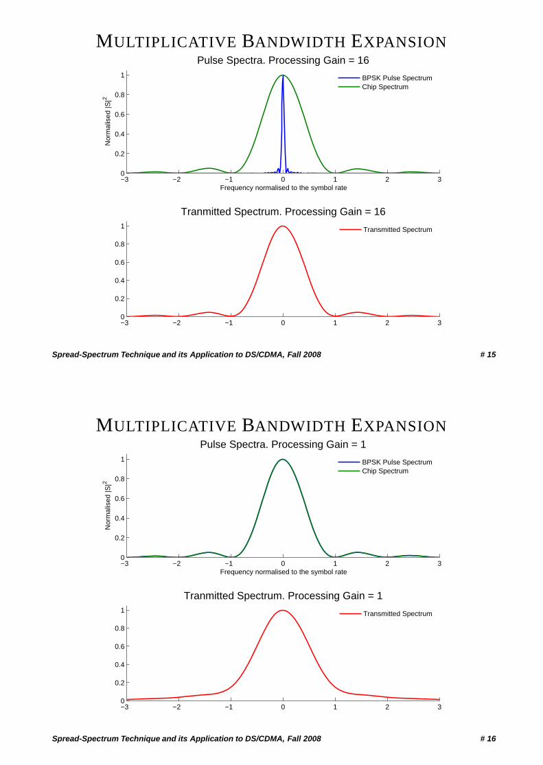
MULTIPLICATIVE BANDWIDTH EXPANSION
−3 −2 −1 0 1 2 30
0.2
0.4
0.6
0.8
1
Pulse Spectra. Processing Gain = 16
Frequency normalised to the symbol rate
Nor
mal
ised
|S|2
−3 −2 −1 0 1 2 30
0.2
0.4
0.6
0.8
1
Tranmitted Spectrum. Processing Gain = 16
BPSK Pulse SpectrumChip Spectrum
Transmitted Spectrum
Spread-Spectrum Technique and its Application to DS/CDMA, Fall 2008 # 15
MULTIPLICATIVE BANDWIDTH EXPANSION
−3 −2 −1 0 1 2 30
0.2
0.4
0.6
0.8
1
Pulse Spectra. Processing Gain = 1
Frequency normalised to the symbol rate
Nor
mal
ised
|S|2
−3 −2 −1 0 1 2 30
0.2
0.4
0.6
0.8
1
Tranmitted Spectrum. Processing Gain = 1
BPSK Pulse SpectrumChip Spectrum
Transmitted Spectrum
Spread-Spectrum Technique and its Application to DS/CDMA, Fall 2008 # 16
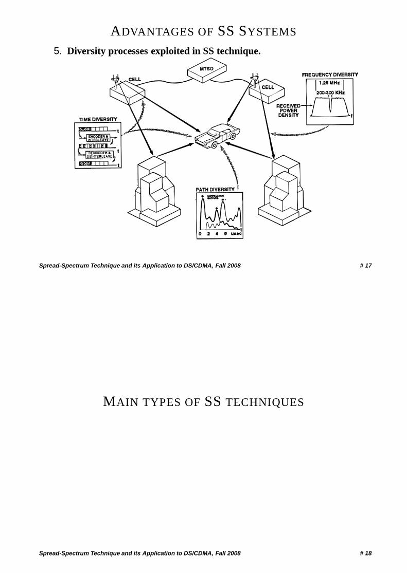
ADVANTAGES OF SS SYSTEMS
5. Diversity processes exploited in SS technique.
Spread-Spectrum Technique and its Application to DS/CDMA, Fall 2008 # 17
MAIN TYPES OF SS TECHNIQUES
Spread-Spectrum Technique and its Application to DS/CDMA, Fall 2008 # 18
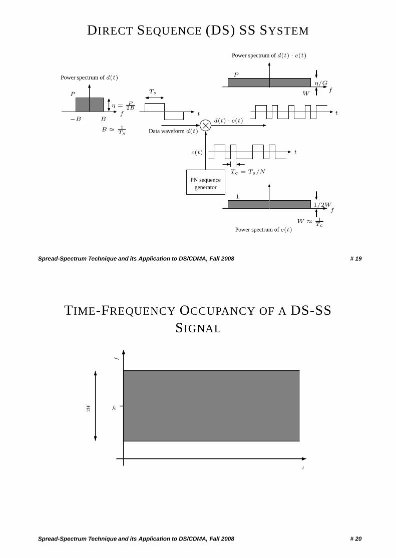
DIRECT SEQUENCE (DS) SS SYSTEM
t−B B
f
Power spectrum of d(t)
t
Ts
d(t) · c(t)
Data waveform d(t)
PN sequencegenerator
c(t)
P
η = P2B
t
Tc = Ts/N
P
Power spectrum of d(t) · c(t)
η/Gf
W ≈ 1Tc
Power spectrum of c(t)
f1/2W
1
W
B ≈ 1Ts
Spread-Spectrum Technique and its Application to DS/CDMA, Fall 2008 # 19
TIME-FREQUENCY OCCUPANCY OF A DS-SSSIGNAL
2W f0
f
t
Spread-Spectrum Technique and its Application to DS/CDMA, Fall 2008 # 20
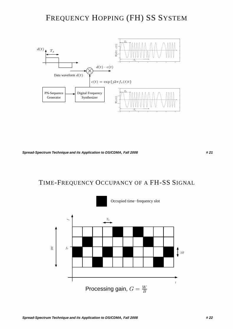
FREQUENCY HOPPING (FH) SS SYSTEM
Tsd(t)
d(t) · c(t)
Data waveform d(t)
Digital FrequencySynthesizer
PN-SequenceGenerator
c(t) = exp{j2πfc(t)t}
0 1 2 3 4 5 6−1.5
−1
−0.5
0
0.5
1
1.5
Ts
Th
�{d(t
)·c
(t)}
0 1 2 3 4 5 6−1.5
−1
−0.5
0
0.5
1
1.5
Ts
Th
�{c(
t)}
Spread-Spectrum Technique and its Application to DS/CDMA, Fall 2008 # 21
TIME-FREQUENCY OCCUPANCY OF A FH-SS SIGNAL
Occupied time−frequency slot
2W f0
f
t
2B
Th
Processing gain, G = WB
Spread-Spectrum Technique and its Application to DS/CDMA, Fall 2008 # 22

MULTI-CARRIER CDMA
Com
bine
r
PN-SequenceGenerator
PN-SequenceGenerator
fc[M ]
fc[2]
fc[1]
chip #1
chip #2
chip #M
fc[2]
fc[1]
fc[M ]
chip #1
chip #2
chip #M
Synchronized
Transmitter Receiver
bit stream
Code vectorCode vector
bit streamModulator Demodulator
Spread-Spectrum Technique and its Application to DS/CDMA, Fall 2008 # 23
ACCESS TECHNIQUES
Spread-Spectrum Technique and its Application to DS/CDMA, Fall 2008 # 24
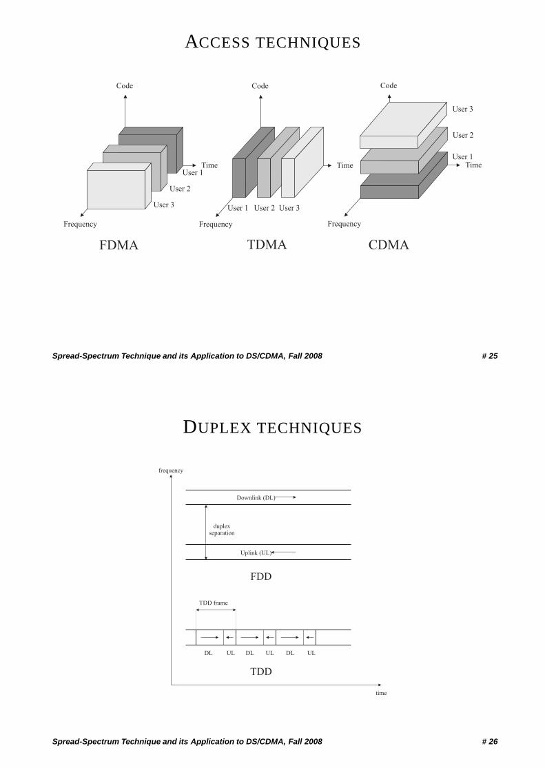
ACCESS TECHNIQUES
Frequency
Time
Code
Frequency
Time
Code
Frequency
Time
Code
User 1
User 2
User 3 User 1 User 2 User 3
User 1
User 2
User 3
FDMA TDMA CDMA
Spread-Spectrum Technique and its Application to DS/CDMA, Fall 2008 # 25
DUPLEX TECHNIQUES
Downlink (DL)
Uplink (UL)
duplexseparation
FDD
DL DL DLUL UL UL
TDD
time
frequency
TDD frame
Spread-Spectrum Technique and its Application to DS/CDMA, Fall 2008 # 26
THEORY AND APPLICATION OF PSEUDO RANDOMBINARY SEQUENCES
Spread-Spectrum Technique and its Application to DS/CDMA, Fall 2008 # 27
PROPERTIES OF RANDOM BINARY SEQUENCESLet us consider a set S of periodic sequences of same length N .
Example:
S = {(000111101011001), (010011010111100)}
In order for these sequences to be “pseudo-random” or “pseudo-noise(PN)” sequences, they have to satisfy the following properties:
• Balance Property
For each sequence in S the relative frequencies of “0” and “1”approximately equal 1
2 each.
• Run Property
For each sequence in S the relative frequencies of runs “0 0 . . . 0︸ ︷︷ ︸m
”
and “1 1 . . . 1︸ ︷︷ ︸m
” of length m approximately equal 12m each.
Spread-Spectrum Technique and its Application to DS/CDMA, Fall 2008 # 28
PROPERTIES OF RANDOM BINARY SEQUENCES (CONT’D)
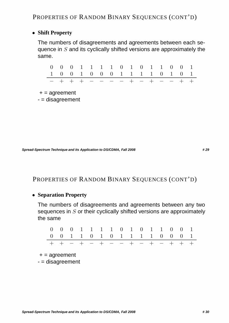
• Shift Property
The numbers of disagreements and agreements between each se-quence in S and its cyclically shifted versions are approximately thesame.
0 0 0 1 1 1 1 0 1 0 1 1 0 0 11 0 0 1 0 0 0 1 1 1 1 0 1 0 1− + + + − − − − + − + − − + +
+ = agreement- = disagreement
Spread-Spectrum Technique and its Application to DS/CDMA, Fall 2008 # 29
PROPERTIES OF RANDOM BINARY SEQUENCES (CONT’D)
• Separation Property
The numbers of disagreements and agreements between any twosequences in S or their cyclically shifted versions are approximatelythe same
0 0 0 1 1 1 1 0 1 0 1 1 0 0 10 0 1 1 0 1 0 1 1 1 1 0 0 0 1+ + − + − + − − + − + − + + +
+ = agreement- = disagreement
Spread-Spectrum Technique and its Application to DS/CDMA, Fall 2008 # 30
AUTOCORRELATION OF BINARY SEQUENCES
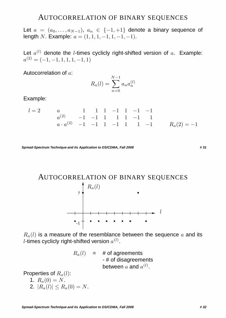
Let a = (a0, . . . , aN−1), an ∈ {−1,+1} denote a binary sequence oflength N . Example: a = (1, 1, 1,−1, 1,−1,−1).
Let a(l) denote the l-times cyclicly right-shifted version of a. Example:a(2) = (−1,−1, 1, 1, 1,−1, 1)
Autocorrelation of a:
Ra(l) =N−1∑n=0
ana(l)n
Example:
l = 2 a 1 1 1 −1 1 −1 −1a(2) −1 −1 1 1 1 −1 1a · a(2) −1 −1 1 −1 1 1 −1 Ra(2) = −1
Spread-Spectrum Technique and its Application to DS/CDMA, Fall 2008 # 31
AUTOCORRELATION OF BINARY SEQUENCES
7
-1
Ra(l)
l
Ra(l) is a measure of the resemblance between the sequence a and itsl-times cyclicly right-shifted version a(l).
Ra(l) = # of agreements- # of disagreementsbetween a and a(l).
Properties of Ra(l):1. Ra(0) = N .2. |Ra(l)| ≤ Ra(0) = N .
Spread-Spectrum Technique and its Application to DS/CDMA, Fall 2008 # 32
CROSSCORRELATION OF BINARY SEQUENCES
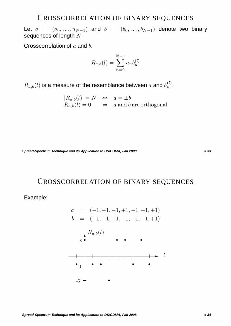
Let a = (a0, . . . , aN−1) and b = (b0, . . . , bN−1) denote two binarysequences of length N .
Crosscorrelation of a and b:
Ra,b(l) =N−1∑n=0
anb(l)n
Ra,b(l) is a measure of the resemblance between a and b(l)n .
|Ra,b(l)| = N ⇔ a = ±bRa,b(l) = 0 ⇔ a and b are orthogonal
Spread-Spectrum Technique and its Application to DS/CDMA, Fall 2008 # 33
CROSSCORRELATION OF BINARY SEQUENCES
Example:
a = (−1,−1,−1,+1,−1,+1,+1)b = (−1,+1,−1,−1,−1,+1,+1)
-1
l
3
-5
Ra,b(l)
Spread-Spectrum Technique and its Application to DS/CDMA, Fall 2008 # 34
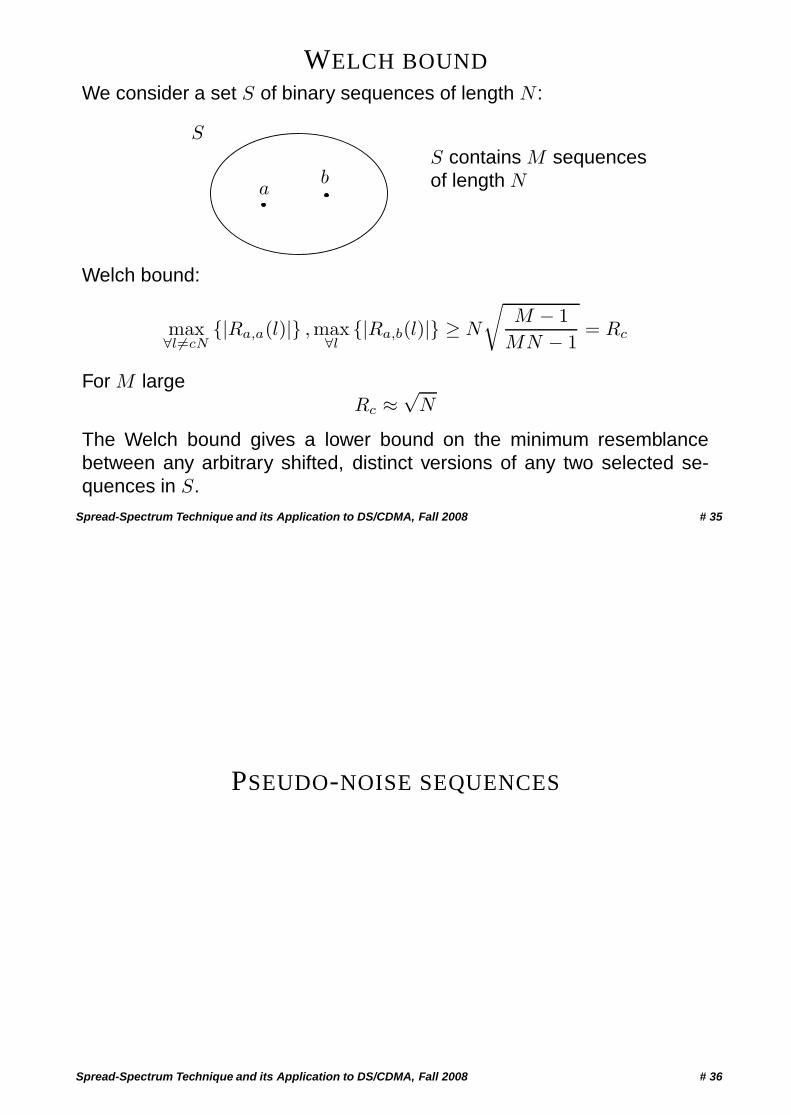
WELCH BOUNDWe consider a set S of binary sequences of length N :
ab
S
S contains M sequencesof length N
Welch bound:
max∀l �=cN
{|Ra,a(l)|} ,max∀l
{|Ra,b(l)|} ≥ N
√M − 1
MN − 1= Rc
For M largeRc ≈
√N
The Welch bound gives a lower bound on the minimum resemblancebetween any arbitrary shifted, distinct versions of any two selected se-quences in S.
Spread-Spectrum Technique and its Application to DS/CDMA, Fall 2008 # 35
PSEUDO-NOISE SEQUENCES
Spread-Spectrum Technique and its Application to DS/CDMA, Fall 2008 # 36
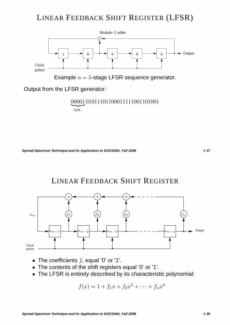
LINEAR FEEDBACK SHIFT REGISTER (LFSR)
1 0 0 0 0
Modulo−2 adder
Output
Clockpulses
Example n = 5-stage LFSR sequence generator.
Output from the LFSR generator:
00001︸ ︷︷ ︸init.
01011101100011111001101001
Spread-Spectrum Technique and its Application to DS/CDMA, Fall 2008 # 37
LINEAR FEEDBACK SHIFT REGISTER
Output
Clockpulses
am f1 f2 f3 fn
am−1 am−2 am−3 am−n
• The coefficients fi equal ’0’ or ’1’.• The contents of the shift registers equal ’0’ or ’1’.• The LFSR is entirely described by its characteristic polynomial:
f(x) = 1 + f1x + f2x2 + · · · + fnxn
Spread-Spectrum Technique and its Application to DS/CDMA, Fall 2008 # 38
PROPERTIES OF SEQUENCES GENERATED BY LFSRS
• A sequence generated by a LFSR is periodic with length N , where
N ≤ 2n − 1.
• If N = 2n−1, then the sequence is referred to as a maximum-length(ML) sequence or pseudo-noise (PN) sequence.
• A LFSR generates a PN sequence if, and only if, its characteristicpolynomial is primitive.
Spread-Spectrum Technique and its Application to DS/CDMA, Fall 2008 # 39
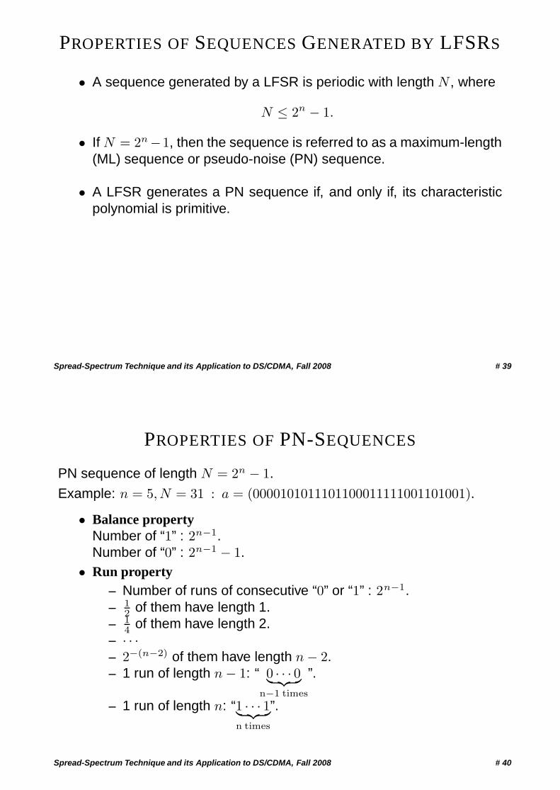
PROPERTIES OF PN-SEQUENCES
PN sequence of length N = 2n − 1.
Example: n = 5, N = 31 : a = (0000101011101100011111001101001).
• Balance propertyNumber of “1” : 2n−1.Number of “0” : 2n−1 − 1.
• Run property– Number of runs of consecutive “0” or “1” : 2n−1.– 1
2 of them have length 1.– 1
4 of them have length 2.– · · ·– 2−(n−2) of them have length n − 2.– 1 run of length n − 1: “ 0 · · · 0︸ ︷︷ ︸
n−1 times
”.
– 1 run of length n: “1 · · · 1︸ ︷︷ ︸n times
”.
Spread-Spectrum Technique and its Application to DS/CDMA, Fall 2008 # 40
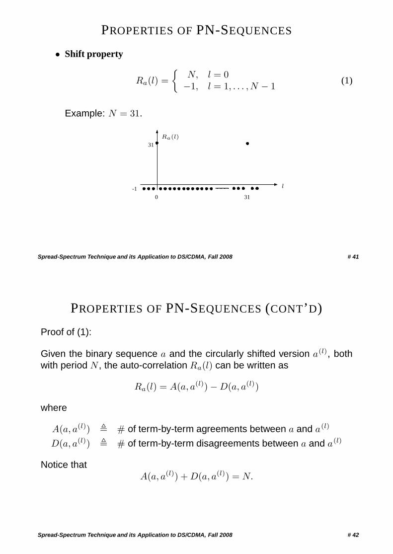
PROPERTIES OF PN-SEQUENCES
• Shift property
Ra(l) ={
N, l = 0−1, l = 1, . . . , N − 1 (1)
Example: N = 31.
31
0
-1 l
Ra(l)
31
Spread-Spectrum Technique and its Application to DS/CDMA, Fall 2008 # 41
PROPERTIES OF PN-SEQUENCES (CONT’D)
Proof of (1):
Given the binary sequence a and the circularly shifted version a(l), bothwith period N , the auto-correlation Ra(l) can be written as
Ra(l) = A(a, a(l)) − D(a, a(l))
where
A(a, a(l)) � # of term-by-term agreements between a and a(l)
D(a, a(l)) � # of term-by-term disagreements between a and a(l)
Notice thatA(a, a(l)) + D(a, a(l)) = N.
Spread-Spectrum Technique and its Application to DS/CDMA, Fall 2008 # 42
PROPERTIES OF PN-SEQUENCES (CONT’D)
Let W (a) be the Hamming weight of a. Then,
D(a, a(l)) = W (a ⊕ a(l)).
Thus,Ra(l) =
(N − W (a ⊕ a(l))
)− W (a ⊕ a(l)).
For ML sequences,
W (a ⊕ a(l �=iN)) = W (a) = (N + 1)/2.
Hence,
Ra(l = iN) = N − 2W (a ⊕ a(l))= N − 2W (a)= −1. �
Spread-Spectrum Technique and its Application to DS/CDMA, Fall 2008 # 43
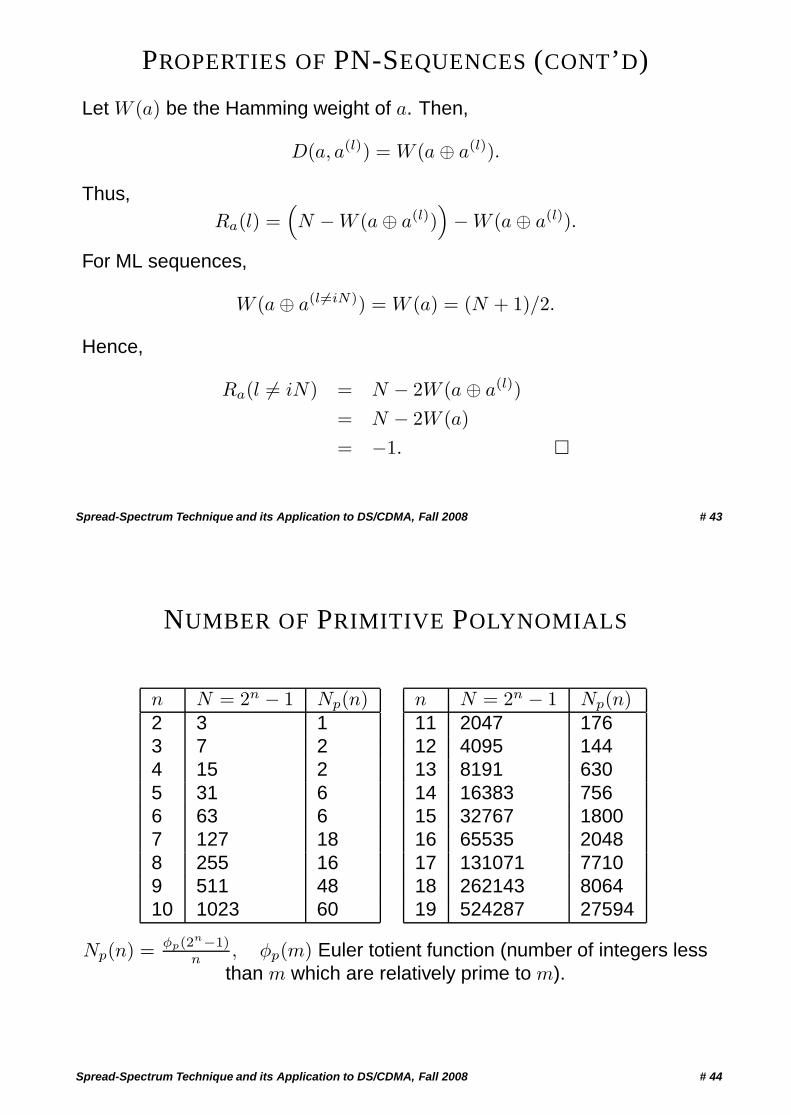
NUMBER OF PRIMITIVE POLYNOMIALS
n N = 2n − 1 Np(n)2 3 13 7 24 15 25 31 66 63 67 127 188 255 169 511 4810 1023 60
n N = 2n − 1 Np(n)11 2047 17612 4095 14413 8191 63014 16383 75615 32767 180016 65535 204817 131071 771018 262143 806419 524287 27594
Np(n) = φp(2n−1)n , φp(m) Euler totient function (number of integers less
than m which are relatively prime to m).
Spread-Spectrum Technique and its Application to DS/CDMA, Fall 2008 # 44
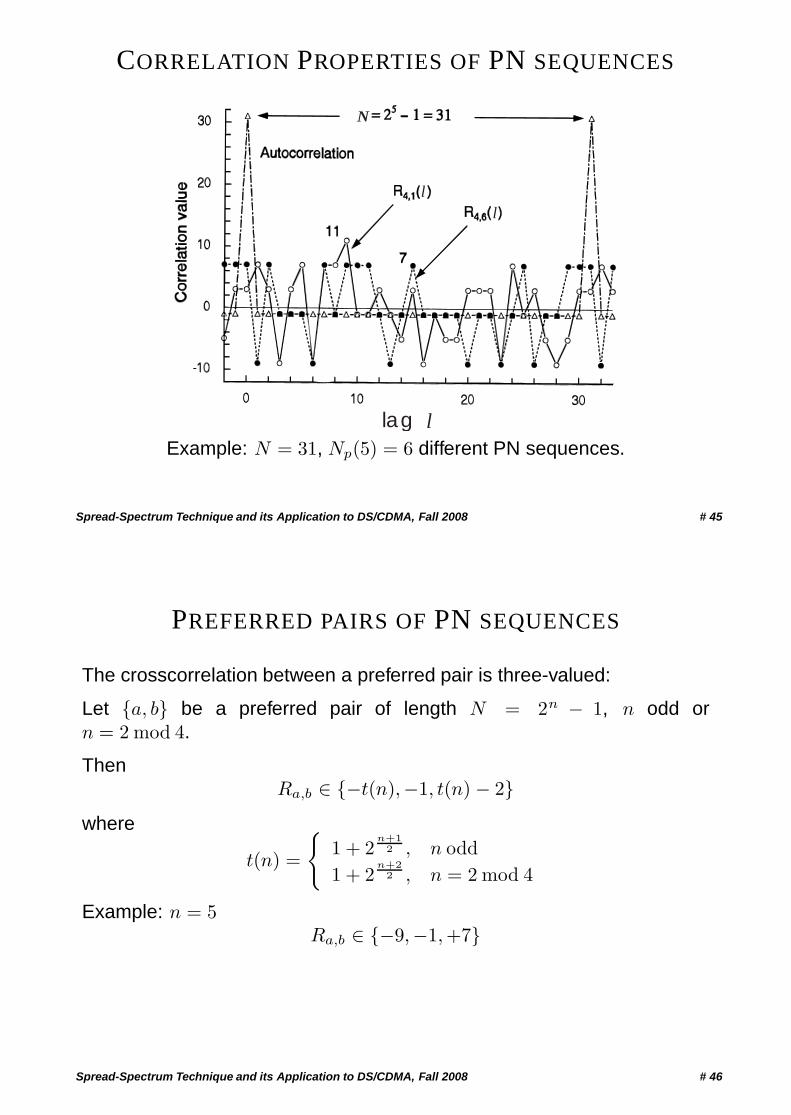
CORRELATION PROPERTIES OF PN SEQUENCES
l
N
l
lag lExample: N = 31, Np(5) = 6 different PN sequences.
Spread-Spectrum Technique and its Application to DS/CDMA, Fall 2008 # 45
PREFERRED PAIRS OF PN SEQUENCES
The crosscorrelation between a preferred pair is three-valued:
Let {a, b} be a preferred pair of length N = 2n − 1, n odd orn = 2 mod 4.
ThenRa,b ∈ {−t(n),−1, t(n) − 2}
where
t(n) =
{1 + 2
n+12 , n odd
1 + 2n+2
2 , n = 2 mod 4
Example: n = 5Ra,b ∈ {−9,−1,+7}
Spread-Spectrum Technique and its Application to DS/CDMA, Fall 2008 # 46
DEFINITION AND PROPERTIES OF GOLD SEQUENCES
Let {a, b} be a preferred pair of PN sequences of length N = 2n − 1.
Set of Gold sequences:
{a, b, a ⊕ b, a ⊕ b(1), . . . , a ⊕ b(N−1)}
Number of Gold sequences: N + 2 = 2n + 1.
Let c and c′ denote two Gold sequences from the above set.
• Autocorrelation property:
Rc(l){
= N, l = 0∈ {−t(n),−1, t(n) − 2} l = 1, . . . , N − 1
Spread-Spectrum Technique and its Application to DS/CDMA, Fall 2008 # 47
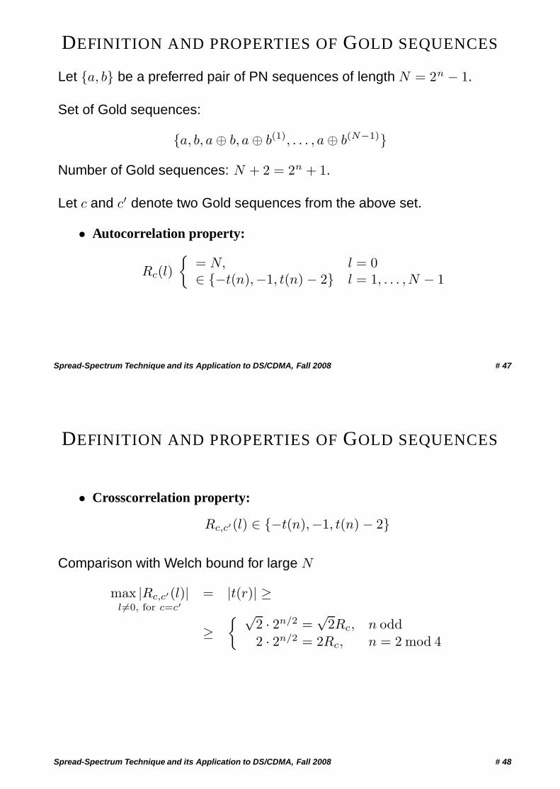
DEFINITION AND PROPERTIES OF GOLD SEQUENCES
• Crosscorrelation property:
Rc,c′(l) ∈ {−t(n),−1, t(n) − 2}
Comparison with Welch bound for large N
max |Rc,c′(l)|l �=0, for c=c′
= |t(r)| ≥
≥{ √
2 · 2n/2 =√
2Rc, n odd2 · 2n/2 = 2Rc, n = 2 mod 4
Spread-Spectrum Technique and its Application to DS/CDMA, Fall 2008 # 48
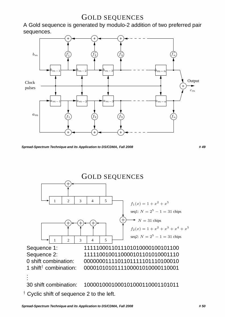
GOLD SEQUENCESA Gold sequence is generated by modulo-2 addition of two preferred pairsequences.
pulsesClock Output
am
bm
am−2am−1 am−3 am−n
bm−nbm−3bm−2bm−1
f ′1 f ′
2 f ′3
f1 f2 f3 fn
f ′n
cm
Spread-Spectrum Technique and its Application to DS/CDMA, Fall 2008 # 49
GOLD SEQUENCES
2 3 4 51
2 3 4 51
f2(x) = 1 + x2 + x3 + x4 + x5
seq2: N = 25 − 1 = 31 chips
f1(x) = 1 + x2 + x5
seq1: N = 25 − 1 = 31 chips
N = 31 chips
Sequence 1: 1111100011011101010000100101100Sequence 2: 11111001001100001011010100011100 shift combination: 00000001111011011111011101000101 shift† combination: 0000101010111100001010000110001...30 shift combination: 1000010001000101000110001101011
† Cyclic shift of sequence 2 to the left.
Spread-Spectrum Technique and its Application to DS/CDMA, Fall 2008 # 50
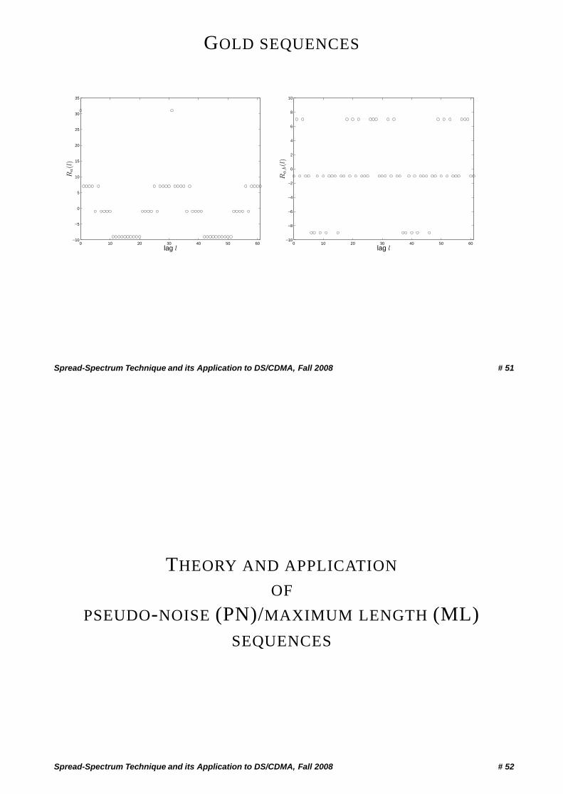
GOLD SEQUENCES
0 10 20 30 40 50 60−10
−5
0
5
10
15
20
25
30
35
lag l
Ra(l
)
0 10 20 30 40 50 60−10
−8
−6
−4
−2
0
2
4
6
8
10
lag l
Ra,b(l
)
Spread-Spectrum Technique and its Application to DS/CDMA, Fall 2008 # 51
THEORY AND APPLICATION
OF
PSEUDO-NOISE (PN)/MAXIMUM LENGTH (ML)SEQUENCES
Spread-Spectrum Technique and its Application to DS/CDMA, Fall 2008 # 52
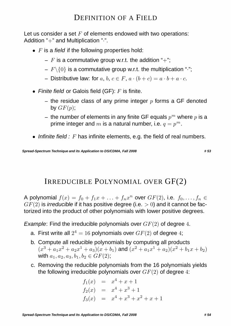
DEFINITION OF A FIELD
Let us consider a set F of elements endowed with two operations:Addition ”+” and Multiplication ”·”.
• F is a field if the following properties hold:
– F is a commutative group w.r.t. the addition “+”;
– F\{0} is a commutative group w.r.t. the multiplication “·”;– Distributive law: for a, b, c ∈ F , a · (b + c) = a · b + a · c.
• Finite field or Galois field (GF): F is finite.
– the residue class of any prime integer p forms a GF denotedby GF (p);
– the number of elements in any finite GF equals pm where p is aprime integer and m is a natural number, i.e. q = pm.
• Infinite field : F has infinite elements, e.g. the field of real numbers.
Spread-Spectrum Technique and its Application to DS/CDMA, Fall 2008 # 53
IRREDUCIBLE POLYNOMIAL OVER GF(2)
A polynomial f(x) = f0 + f1x + . . . + fnxn over GF (2), i.e. f0, . . . , fn ∈GF (2) is irreducible if it has positive degree (i.e. > 0) and it cannot be fac-torized into the product of other polynomials with lower positive degrees.
Example: Find the irreducible polynomials over GF (2) of degree 4.
a. First write all 24 = 16 polynomials over GF (2) of degree 4;
b. Compute all reducible polynomials by computing all products(x3 + a1x
2 + a2x1 + a3)(x + b1) and (x2 + a1x
1 + a2)(x2 + b1x + b2)with a1, a2, a3, b1, b2 ∈ GF (2);
c. Removing the reducible polynomials from the 16 polynomials yieldsthe following irreducible polynomials over GF (2) of degree 4:
f1(x) = x4 + x + 1f2(x) = x4 + x3 + 1f3(x) = x4 + x3 + x2 + x + 1
Spread-Spectrum Technique and its Application to DS/CDMA, Fall 2008 # 54
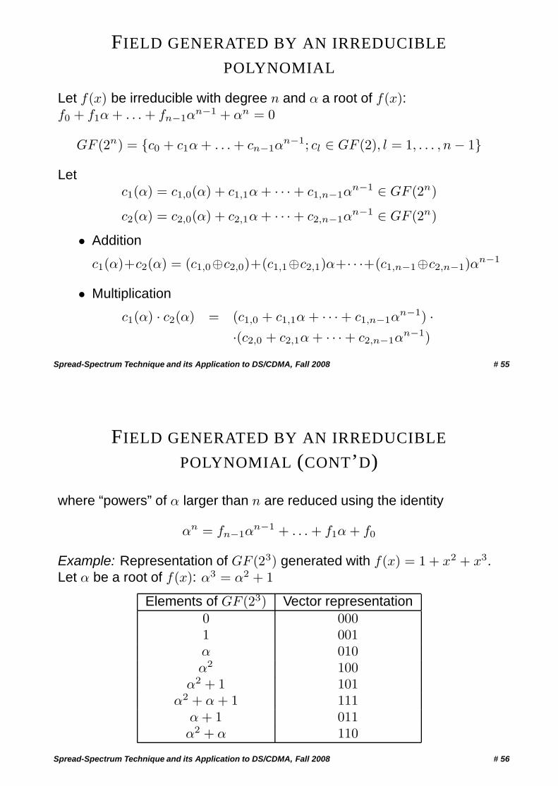
FIELD GENERATED BY AN IRREDUCIBLE
POLYNOMIAL
Let f(x) be irreducible with degree n and α a root of f(x):f0 + f1α + . . . + fn−1α
n−1 + αn = 0
GF (2n) = {c0 + c1α + . . . + cn−1αn−1; cl ∈ GF (2), l = 1, . . . , n − 1}
Letc1(α) = c1,0(α) + c1,1α + · · · + c1,n−1α
n−1 ∈ GF (2n)
c2(α) = c2,0(α) + c2,1α + · · · + c2,n−1αn−1 ∈ GF (2n)
• Addition
c1(α)+c2(α) = (c1,0⊕c2,0)+(c1,1⊕c2,1)α+· · ·+(c1,n−1⊕c2,n−1)αn−1
• Multiplication
c1(α) · c2(α) = (c1,0 + c1,1α + · · · + c1,n−1αn−1) ·
·(c2,0 + c2,1α + · · · + c2,n−1αn−1)
Spread-Spectrum Technique and its Application to DS/CDMA, Fall 2008 # 55
FIELD GENERATED BY AN IRREDUCIBLE
POLYNOMIAL (CONT’D)
where “powers” of α larger than n are reduced using the identity
αn = fn−1αn−1 + . . . + f1α + f0
Example: Representation of GF (23) generated with f(x) = 1 + x2 + x3.Let α be a root of f(x): α3 = α2 + 1
Elements of GF (23) Vector representation0 0001 001α 010α2 100
α2 + 1 101α2 + α + 1 111
α + 1 011α2 + α 110
Spread-Spectrum Technique and its Application to DS/CDMA, Fall 2008 # 56
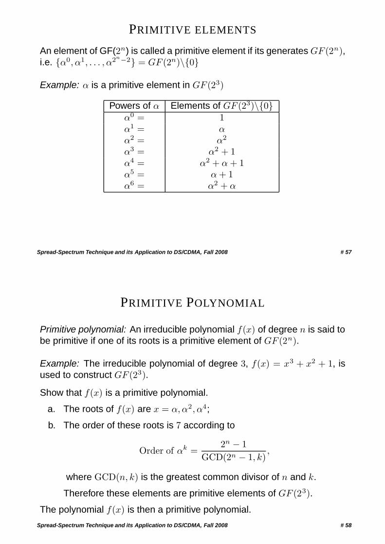
PRIMITIVE ELEMENTS
An element of GF(2n) is called a primitive element if its generates GF (2n),i.e. {α0, α1, . . . , α2n−2} = GF (2n)\{0}
Example: α is a primitive element in GF (23)
Powers of α Elements of GF (23)\{0}α0 = 1α1 = αα2 = α2
α3 = α2 + 1α4 = α2 + α + 1α5 = α + 1α6 = α2 + α
Spread-Spectrum Technique and its Application to DS/CDMA, Fall 2008 # 57
PRIMITIVE POLYNOMIAL
Primitive polynomial: An irreducible polynomial f(x) of degree n is said tobe primitive if one of its roots is a primitive element of GF (2n).
Example: The irreducible polynomial of degree 3, f(x) = x3 + x2 + 1, isused to construct GF (23).
Show that f(x) is a primitive polynomial.
a. The roots of f(x) are x = α,α2, α4;
b. The order of these roots is 7 according to
Order of αk =2n − 1
GCD(2n − 1, k),
where GCD(n, k) is the greatest common divisor of n and k.
Therefore these elements are primitive elements of GF (23).
The polynomial f(x) is then a primitive polynomial.
Spread-Spectrum Technique and its Application to DS/CDMA, Fall 2008 # 58
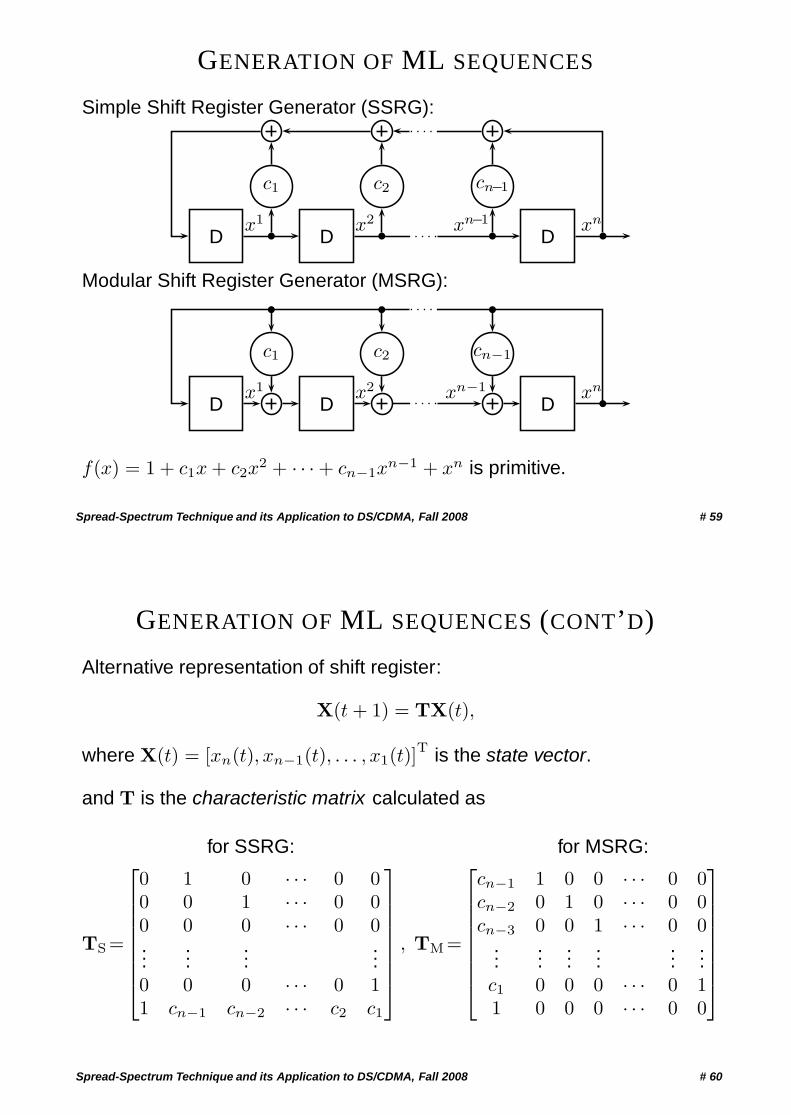
GENERATION OF ML SEQUENCES
Simple Shift Register Generator (SSRG):
D
c1
D
c2
D
cn−1
x1 x2 xn−1 xn
Modular Shift Register Generator (MSRG):
D
c1
D
c2
D
cn−1
x1 x2 xn−1 xn
f(x) = 1 + c1x + c2x2 + · · · + cn−1x
n−1 + xn is primitive.
Spread-Spectrum Technique and its Application to DS/CDMA, Fall 2008 # 59
GENERATION OF ML SEQUENCES (CONT’D)
Alternative representation of shift register:
X(t + 1) = TX(t),
where X(t) = [xn(t), xn−1(t), . . . , x1(t)]T is the state vector.
and T is the characteristic matrix calculated as
TS =
⎡⎢⎢⎢⎢⎢⎢⎢⎣
0 1 0
for SSRG:
· · · 0 00 0 1 · · · 0 00 0 0 · · · 0 0...
......
...0 0 0 · · · 0 11 cn−1 cn−2 · · · c2 c1
⎤⎥⎥⎥⎥⎥⎥⎥⎦
, TM =
⎡⎢⎢⎢⎢⎢⎢⎢⎣
cn−1 1 0 0
for MSRG:
· · · 0 0cn−2 0 1 0 · · · 0 0cn−3 0 0 1 · · · 0 0
......
......
......
c1 0 0 0 · · · 0 11 0 0 0 · · · 0 0
⎤⎥⎥⎥⎥⎥⎥⎥⎦
Spread-Spectrum Technique and its Application to DS/CDMA, Fall 2008 # 60
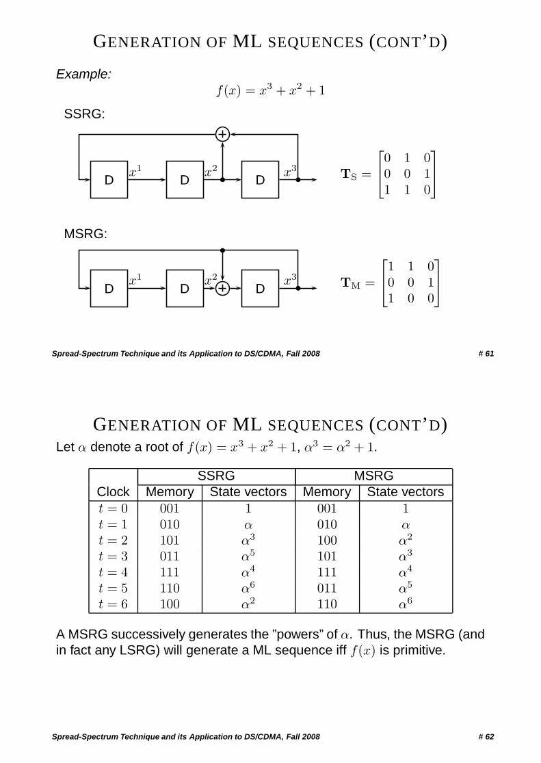
GENERATION OF ML SEQUENCES (CONT’D)
Example:f(x) = x3 + x2 + 1
SSRG:
D D Dx1 x2 x3 TS =
⎡⎣0 1 00 0 11 1 0
⎤⎦
MSRG:
D D Dx1 x2 x3 TM =
⎡⎣1 1 0
0 0 11 0 0
⎤⎦
Spread-Spectrum Technique and its Application to DS/CDMA, Fall 2008 # 61
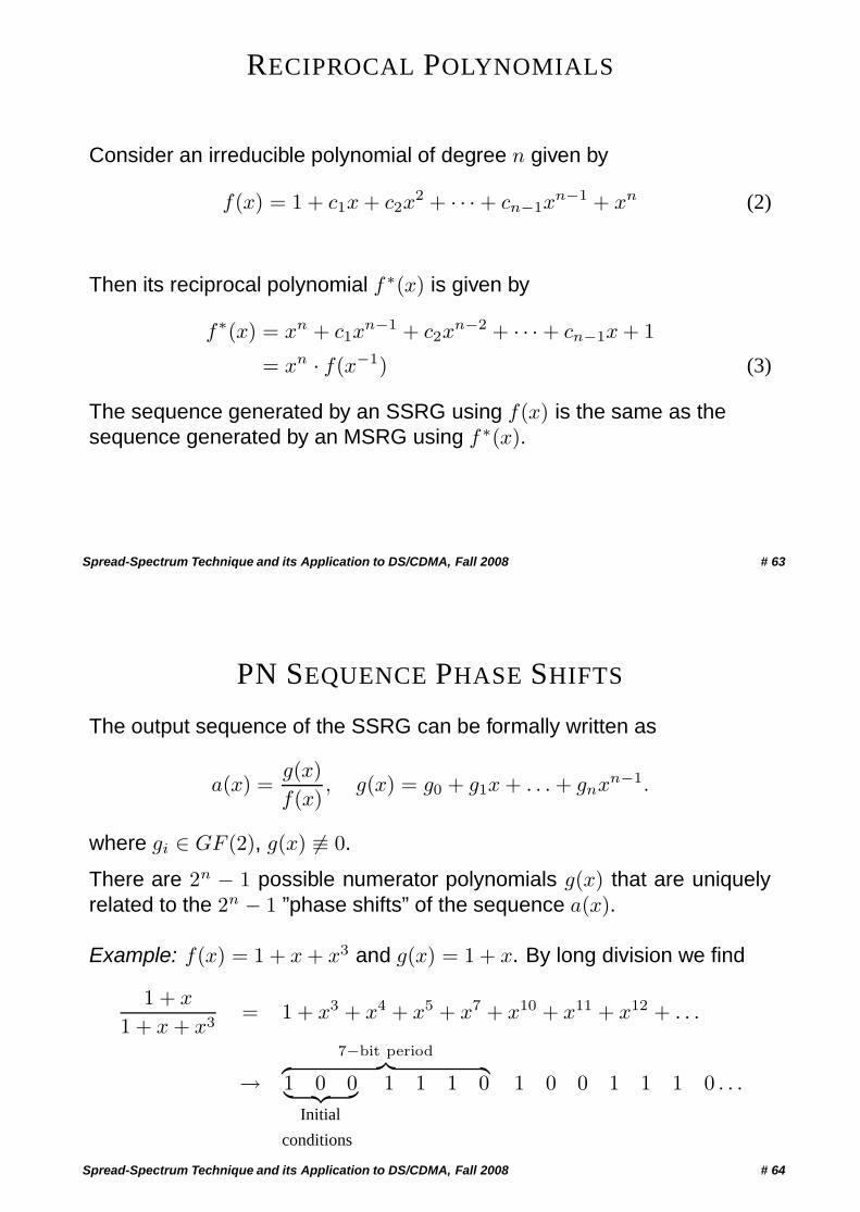
GENERATION OF ML SEQUENCES (CONT’D)Let α denote a root of f(x) = x3 + x2 + 1, α3 = α2 + 1.
SSRG MSRGClock Memory State vectors Memory State vectorst = 0 001 1 001 1t = 1 010 α 010 αt = 2 101 α3 100 α2
t = 3 011 α5 101 α3
t = 4 111 α4 111 α4
t = 5 110 α6 011 α5
t = 6 100 α2 110 α6
A MSRG successively generates the ”powers” of α. Thus, the MSRG (andin fact any LSRG) will generate a ML sequence iff f(x) is primitive.
Spread-Spectrum Technique and its Application to DS/CDMA, Fall 2008 # 62
RECIPROCAL POLYNOMIALS
Consider an irreducible polynomial of degree n given by
f(x) = 1 + c1x + c2x2 + · · · + cn−1x
n−1 + xn (2)
Then its reciprocal polynomial f ∗(x) is given by
f∗(x) = xn + c1xn−1 + c2x
n−2 + · · · + cn−1x + 1
= xn · f(x−1) (3)
The sequence generated by an SSRG using f(x) is the same as thesequence generated by an MSRG using f ∗(x).
Spread-Spectrum Technique and its Application to DS/CDMA, Fall 2008 # 63
PN SEQUENCE PHASE SHIFTS
The output sequence of the SSRG can be formally written as
a(x) =g(x)f(x)
, g(x) = g0 + g1x + . . . + gnxn−1.
where gi ∈ GF (2), g(x) ≡ 0.
There are 2n − 1 possible numerator polynomials g(x) that are uniquelyrelated to the 2n − 1 ”phase shifts” of the sequence a(x).
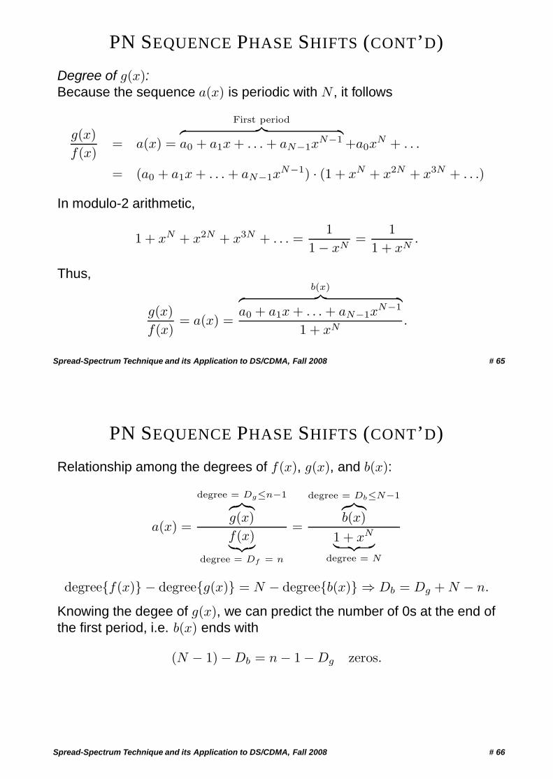
Example: f(x) = 1 + x + x3 and g(x) = 1 + x. By long division we find
1 + x
1 + x + x3= 1 + x3 + x4 + x5 + x7 + x10 + x11 + x12 + . . .
→7−bit period︷ ︸︸ ︷
1 0 0︸ ︷︷ ︸Initial
conditions
1 1 1 0 1 0 0 1 1 1 0 . . .
Spread-Spectrum Technique and its Application to DS/CDMA, Fall 2008 # 64
PN SEQUENCE PHASE SHIFTS (CONT’D)
Degree of g(x):Because the sequence a(x) is periodic with N , it follows
g(x)f(x)
= a(x) =
First period︷ ︸︸ ︷a0 + a1x + . . . + aN−1x
N−1 +a0xN + . . .
= (a0 + a1x + . . . + aN−1xN−1) · (1 + xN + x2N + x3N + . . .)
In modulo-2 arithmetic,
1 + xN + x2N + x3N + . . . =1
1 − xN=
11 + xN
.
Thus,
g(x)f(x)
= a(x) =
b(x)︷ ︸︸ ︷a0 + a1x + . . . + aN−1x
N−1
1 + xN.
Spread-Spectrum Technique and its Application to DS/CDMA, Fall 2008 # 65
PN SEQUENCE PHASE SHIFTS (CONT’D)
Relationship among the degrees of f(x), g(x), and b(x):
a(x) =
degree = Dg≤n−1︷︸︸︷g(x)f(x)︸︷︷︸
degree = Df = n
=
degree = Db≤N−1︷︸︸︷b(x)
1 + xN︸ ︷︷ ︸degree = N
degree{f(x)} − degree{g(x)} = N − degree{b(x)} ⇒ Db = Dg + N − n.
Knowing the degee of g(x), we can predict the number of 0s at the end ofthe first period, i.e. b(x) ends with
(N − 1) − Db = n − 1 − Dg zeros.
Spread-Spectrum Technique and its Application to DS/CDMA, Fall 2008 # 66
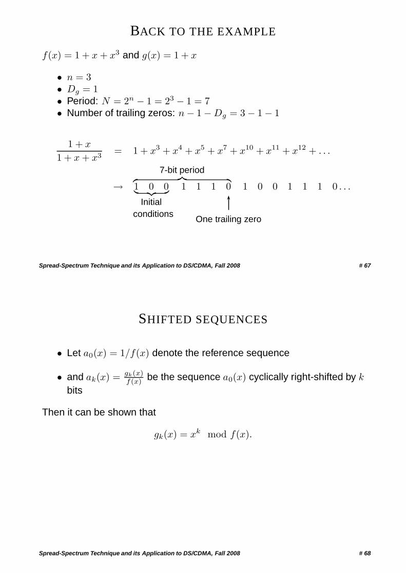
BACK TO THE EXAMPLE
f(x) = 1 + x + x3 and g(x) = 1 + x
• n = 3• Dg = 1• Period: N = 2n − 1 = 23 − 1 = 7• Number of trailing zeros: n − 1 − Dg = 3 − 1 − 1
1 + x
1 + x + x3= 1 + x3 + x4 + x5 + x7 + x10 + x11 + x12 + . . .
→7-bit period︷ ︸︸ ︷
1 0 0︸ ︷︷ ︸Initial
conditions
1 1 1 0
One trailing zero
1 0 0 1 1 1 0 . . .
Spread-Spectrum Technique and its Application to DS/CDMA, Fall 2008 # 67
SHIFTED SEQUENCES
• Let a0(x) = 1/f(x) denote the reference sequence
• and ak(x) = gk(x)f(x) be the sequence a0(x) cyclically right-shifted by k
bits
Then it can be shown that
gk(x) = xk mod f(x).
Spread-Spectrum Technique and its Application to DS/CDMA, Fall 2008 # 68
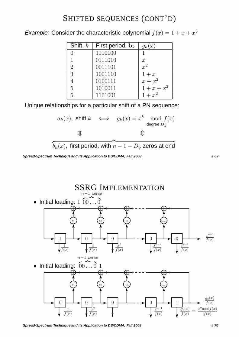
SHIFTED SEQUENCES (CONT’D)
Example: Consider the characteristic polynomial f(x) = 1 + x + x3
Shift, k First period, bk gk(x)0 1110100 11 0111010 x2 0011101 x2
3 1001110 1 + x4 0100111 x + x2
5 1010011 1 + x + x2
6 1101001 1 + x2
Unique relationships for a particular shift of a PN sequence:
ak(x), shift k ⇐⇒ gk(x) = xk mod f(x)degree Dg
� �︷ ︸︸ ︷bk(x), first period, with n − 1 − Dg zeros at end
Spread-Spectrum Technique and its Application to DS/CDMA, Fall 2008 # 69
SSRG IMPLEMENTATION
• Initial loading: 1
n−1 zeros︷ ︸︸ ︷00 . . . 0
0 0 001
cn−1c3c2c1
1f (x)
xf (x)
x2
f (x)xn−2
f (x)xn−1
f (x)
xn−1
f (x)
• Initial loading:
n−1 zeros︷ ︸︸ ︷00 . . . 0 1
0 00
cn−1c3c2c1
xf (x)
x2
f (x)xn−1
f (x)
gn(x)f (x)
gn(x)f (x) = xnmodf (x)
f (x)
0 1
Spread-Spectrum Technique and its Application to DS/CDMA, Fall 2008 # 70
PHASE SHIFTING USING MASKS FOR A SSRG
Phase shift network (PSN)
0 0 001
cn−1c3c2c1
Mask
m0 m1 m2 mn−1mn−2
1f (x)
xf (x)
x2
f (x)xn−2
f (x)xn−1
f (x)
xn−1
f (x)
m(x)f (x)
Spread-Spectrum Technique and its Application to DS/CDMA, Fall 2008 # 71
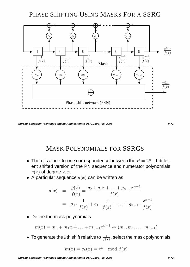
MASK POLYNOMIALS FOR SSRGS
• There is a one-to-one correspondence between the P = 2n−1 differ-ent shifted version of the PN sequence and numerator polynomialsg(x) of degree < n.
• A particular sequence a(x) can be written as
a(x) =g(x)f(x)
=g0 + g1x + . . . + gn−1x
n−1
f(x)
= g0 · 1f(x)
+ g1 · x
f(x)+ . . . + gn−1 · xn−1
f(x)
• Define the mask polynomials
m(x) = m0 + m1x + . . . + mn−1xn−1 ⇔ (m0,m1, . . . ,mn−1)
• To generate the kth shift relative to 1f(x) , select the mask polynomials
m(x) = gk(x) = xk mod f(x)
Spread-Spectrum Technique and its Application to DS/CDMA, Fall 2008 # 72
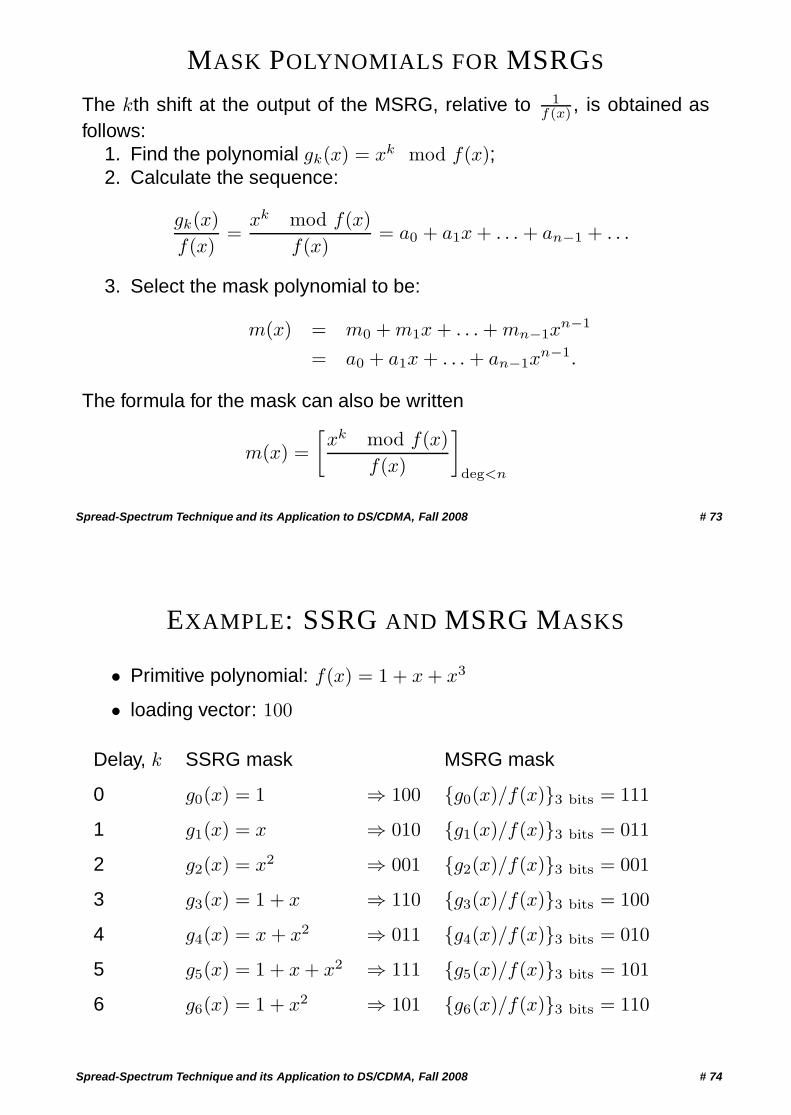
MASK POLYNOMIALS FOR MSRGS
The kth shift at the output of the MSRG, relative to 1f(x) , is obtained as
follows:1. Find the polynomial gk(x) = xk mod f(x);2. Calculate the sequence:
gk(x)f(x)
=xk mod f(x)
f(x)= a0 + a1x + . . . + an−1 + . . .
3. Select the mask polynomial to be:
m(x) = m0 + m1x + . . . + mn−1xn−1
= a0 + a1x + . . . + an−1xn−1.
The formula for the mask can also be written
m(x) =[xk mod f(x)
f(x)
]deg<n
Spread-Spectrum Technique and its Application to DS/CDMA, Fall 2008 # 73
EXAMPLE: SSRG AND MSRG MASKS
• Primitive polynomial: f(x) = 1 + x + x3
• loading vector: 100
Delay, k SSRG mask MSRG mask
0 g0(x) = 1 ⇒ 100 {g0(x)/f(x)}3 bits = 111
1 g1(x) = x ⇒ 010 {g1(x)/f(x)}3 bits = 011
2 g2(x) = x2 ⇒ 001 {g2(x)/f(x)}3 bits = 001
3 g3(x) = 1 + x ⇒ 110 {g3(x)/f(x)}3 bits = 100
4 g4(x) = x + x2 ⇒ 011 {g4(x)/f(x)}3 bits = 010
5 g5(x) = 1 + x + x2 ⇒ 111 {g5(x)/f(x)}3 bits = 101
6 g6(x) = 1 + x2 ⇒ 101 {g6(x)/f(x)}3 bits = 110
Spread-Spectrum Technique and its Application to DS/CDMA, Fall 2008 # 74
SYNCHRONISATION ISSUES
Spread-Spectrum Technique and its Application to DS/CDMA, Fall 2008 # 75
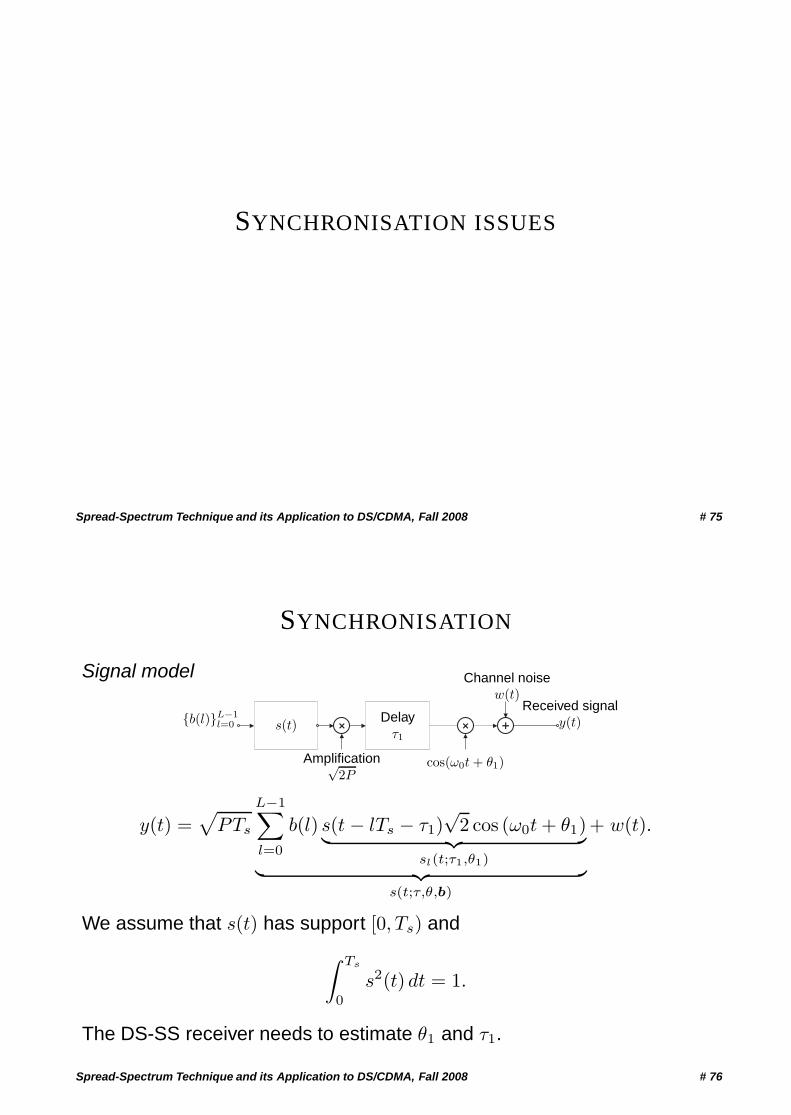
SYNCHRONISATION
Signal model
+ + +{b(l)}L−1
l=0
Amplification√2P
Delayτ1
Channel noisew(t)
Received signaly(t)
cos(ω0t + θ1)
s(t)
y(t) =√
PTs
L−1∑l=0
b(l) s(t − lTs − τ1)√
2 cos (ω0t + θ1)︸ ︷︷ ︸sl(t;τ1,θ1)︸ ︷︷ ︸
s(t;τ,θ,b)
+ w(t).
We assume that s(t) has support [0, Ts) and∫ Ts
0
s2(t) dt = 1.
The DS-SS receiver needs to estimate θ1 and τ1.
Spread-Spectrum Technique and its Application to DS/CDMA, Fall 2008 # 76
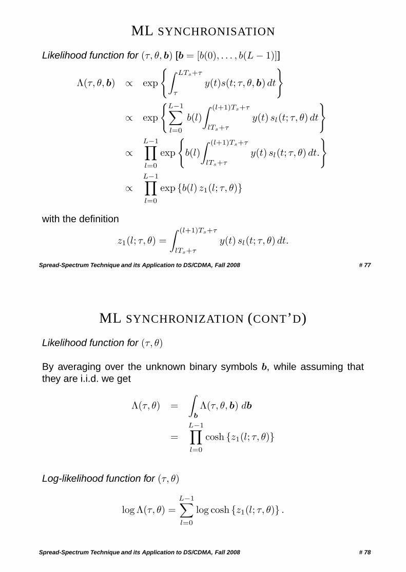
ML SYNCHRONISATION
Likelihood function for (τ, θ, b) [b = [b(0), . . . , b(L − 1)]]
Λ(τ, θ, b) ∝ exp
{∫ LTs+τ
τ
y(t)s(t; τ, θ, b) dt
}
∝ exp
{L−1∑l=0
b(l)∫ (l+1)Ts+τ
lTs+τ
y(t) sl(t; τ, θ) dt
}
∝L−1∏l=0
exp
{b(l)∫ (l+1)Ts+τ
lTs+τ
y(t) sl(t; τ, θ) dt.
}
∝L−1∏l=0
exp {b(l) z1(l; τ, θ)}
with the definition
z1(l; τ, θ) =∫ (l+1)Ts+τ
lTs+τ
y(t) sl(t; τ, θ) dt.
Spread-Spectrum Technique and its Application to DS/CDMA, Fall 2008 # 77
ML SYNCHRONIZATION (CONT’D)
Likelihood function for (τ, θ)
By averaging over the unknown binary symbols b, while assuming thatthey are i.i.d. we get
Λ(τ, θ) =∫
b
Λ(τ, θ, b) db
=L−1∏l=0
cosh {z1(l; τ, θ)}
Log-likelihood function for (τ, θ)
log Λ(τ, θ) =L−1∑l=0
log cosh {z1(l; τ, θ)} .
Spread-Spectrum Technique and its Application to DS/CDMA, Fall 2008 # 78
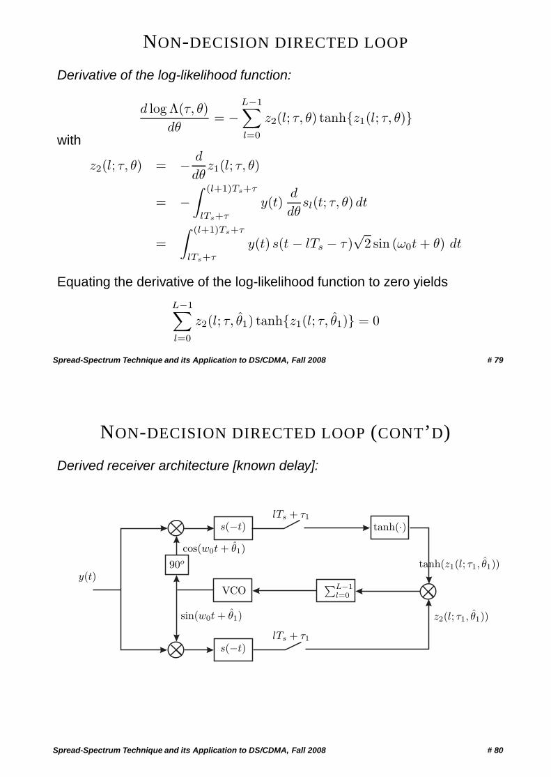
NON-DECISION DIRECTED LOOP
Derivative of the log-likelihood function:
d log Λ(τ, θ)dθ
= −L−1∑l=0
z2(l; τ, θ) tanh{z1(l; τ, θ)}with
z2(l; τ, θ) = − d
dθz1(l; τ, θ)
= −∫ (l+1)Ts+τ
lTs+τ
y(t)d
dθsl(t; τ, θ) dt
=∫ (l+1)Ts+τ
lTs+τ
y(t) s(t − lTs − τ )√
2 sin (ω0t + θ) dt
Equating the derivative of the log-likelihood function to zero yields
L−1∑l=0
z2(l; τ, θ1) tanh{z1(l; τ, θ1)} = 0
Spread-Spectrum Technique and its Application to DS/CDMA, Fall 2008 # 79
NON-DECISION DIRECTED LOOP (CONT’D)
Derived receiver architecture [known delay]:
VCOy(t)
s(−t)
s(−t)
∑L−1l=0
sin(w0t + θ1)
cos(w0t + θ1)90o
tanh(·)
tanh(z1(l; τ1, θ1))
z2(l; τ1, θ1))
lTs + τ1
lTs + τ1
Spread-Spectrum Technique and its Application to DS/CDMA, Fall 2008 # 80
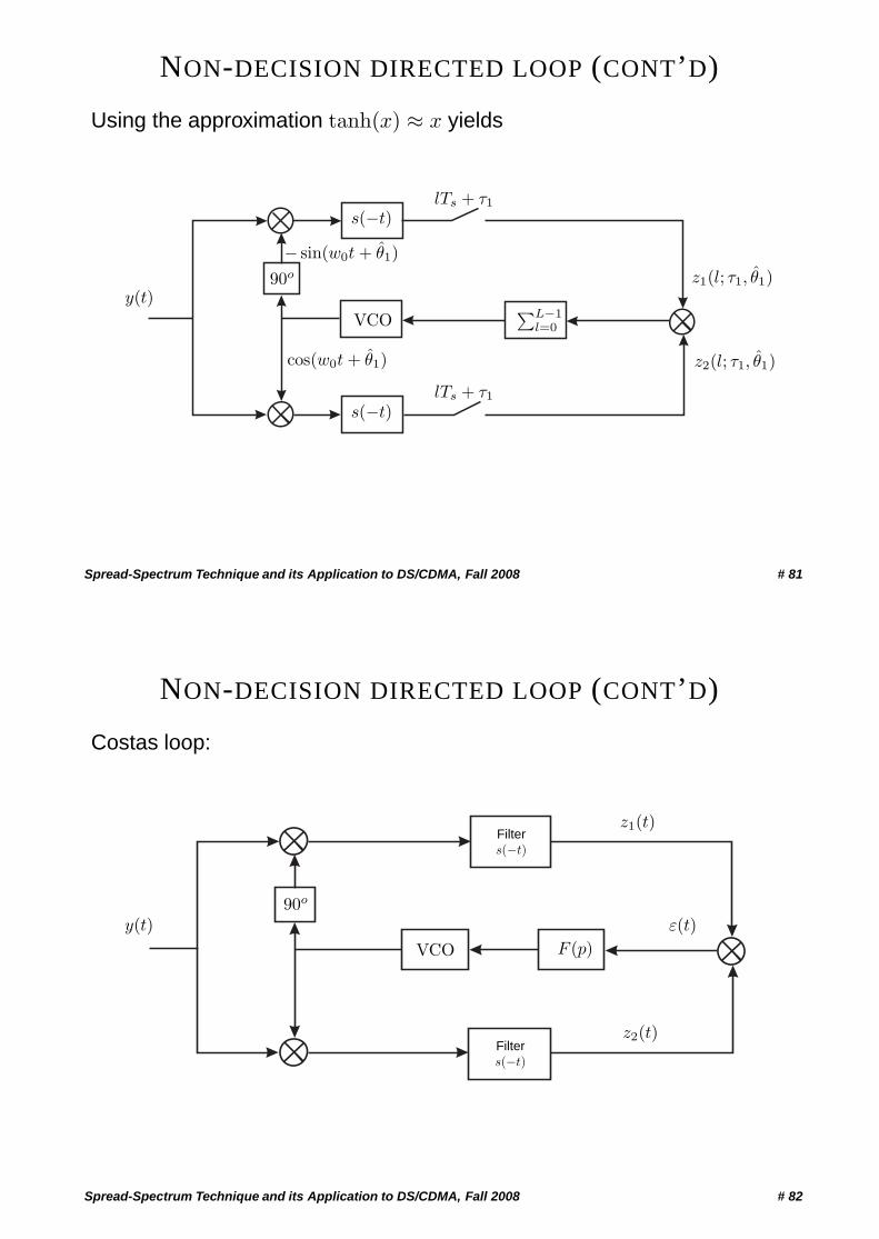
NON-DECISION DIRECTED LOOP (CONT’D)
Using the approximation tanh(x) ≈ x yields
VCOy(t)
s(−t)
s(−t)
∑L−1l=0
cos(w0t + θ1)
− sin(w0t + θ1)90o z1(l; τ1, θ1)
z2(l; τ1, θ1)
lTs + τ1
lTs + τ1
Spread-Spectrum Technique and its Application to DS/CDMA, Fall 2008 # 81
NON-DECISION DIRECTED LOOP (CONT’D)
Costas loop:
VCOy(t)
F (p)
90o
z1(t)
z2(t)
ε(t)
Filters(−t)
Filters(−t)
Spread-Spectrum Technique and its Application to DS/CDMA, Fall 2008 # 82
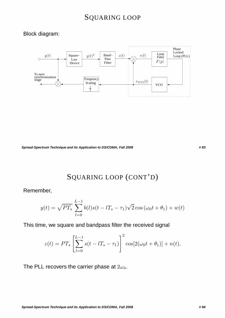
SQUARING LOOP
Block diagram:
Device
Square−Law
Band−
FilterPass
VCO
PhaseLockedLoop (PLL)
synchronizationstage
LoopFilter
To next
ScalingFrequency
f2
ε(t)z(t)
F (p)
rVCO(t)
y(t) y(t)2
Spread-Spectrum Technique and its Application to DS/CDMA, Fall 2008 # 83
SQUARING LOOP (CONT’D)
Remember,
y(t) =√
PTs
L−1∑l=0
b(l)s(t − lTs − τ1)√
2 cos (ω0t + θ1) + w(t)
This time, we square and bandpass filter the received signal
z(t) = PTs
[L−1∑l=0
s(t − lTs − τ1)
]2
cos[2(ω0t + θ1)] + n(t),
The PLL recovers the carrier phase at 2ω0.
Spread-Spectrum Technique and its Application to DS/CDMA, Fall 2008 # 84
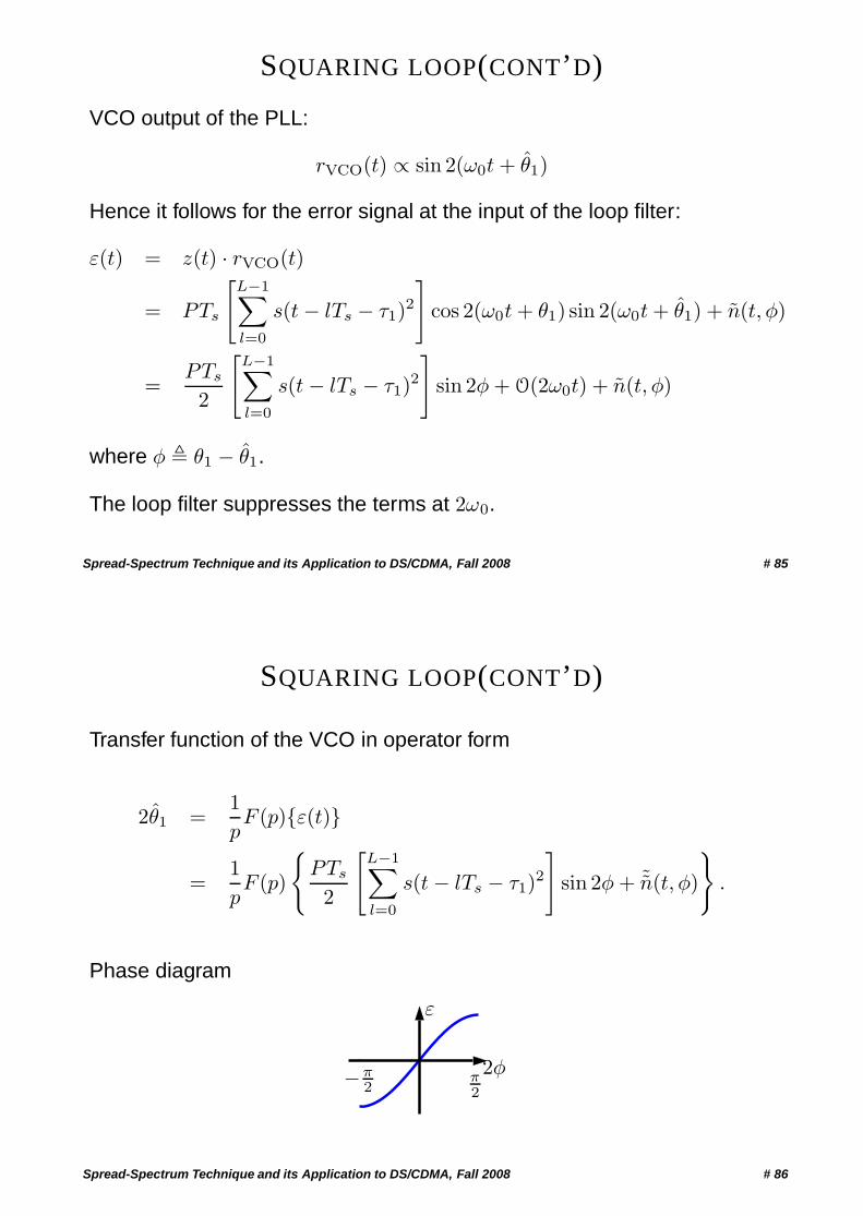
SQUARING LOOP(CONT’D)
VCO output of the PLL:
rVCO(t) ∝ sin 2(ω0t + θ1)
Hence it follows for the error signal at the input of the loop filter:
ε(t) = z(t) · rVCO(t)
= PTs
[L−1∑l=0
s(t − lTs − τ1)2]
cos 2(ω0t + θ1) sin 2(ω0t + θ1) + n(t, φ)
=PTs
2
[L−1∑l=0
s(t − lTs − τ1)2]
sin 2φ + O(2ω0t) + n(t, φ)
where φ � θ1 − θ1.
The loop filter suppresses the terms at 2ω0.
Spread-Spectrum Technique and its Application to DS/CDMA, Fall 2008 # 85
SQUARING LOOP(CONT’D)
Transfer function of the VCO in operator form
2θ1 =1pF (p){ε(t)}
=1pF (p)
{PTs
2
[L−1∑l=0
s(t − lTs − τ1)2]
sin 2φ + ˜n(t, φ)
}.
Phase diagram
ε
π2
−π2
2φ
Spread-Spectrum Technique and its Application to DS/CDMA, Fall 2008 # 86
TIMING SYNCHRONISATION
Spread-Spectrum Technique and its Application to DS/CDMA, Fall 2008 # 87
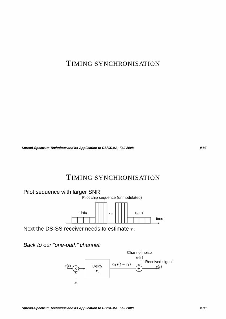
TIMING SYNCHRONISATION
Pilot sequence with larger SNR
· · · datadata
Pilot chip sequence (unmodulated)
time
Next the DS-SS receiver needs to estimate τ .
Back to our ”one-path” channel:
+ +s(t)
α1
Delayτ1
α1s(t − τ1)
Channel noisew(t)
Received signaly(t)
Spread-Spectrum Technique and its Application to DS/CDMA, Fall 2008 # 88
TIMING SYNCHRONISATION (CONT’D)
We distinguish between
• Acquisition: coarse estimate τ1c of τ1
• Tracking: maintaining fine estimate τ1 of τ1, i.e.
|τ1 − τ1| <Tc
Q= δ
Spread-Spectrum Technique and its Application to DS/CDMA, Fall 2008 # 89
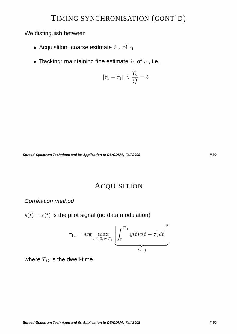
ACQUISITION
Correlation method
s(t) = c(t) is the pilot signal (no data modulation)
τ1c = arg maxτ∈[0,NTc]
∣∣∣∣∣∫ TD
0
y(t)c(t − τ )dt
∣∣∣∣∣2
︸ ︷︷ ︸λ(τ)
where TD is the dwell-time.
Spread-Spectrum Technique and its Application to DS/CDMA, Fall 2008 # 90
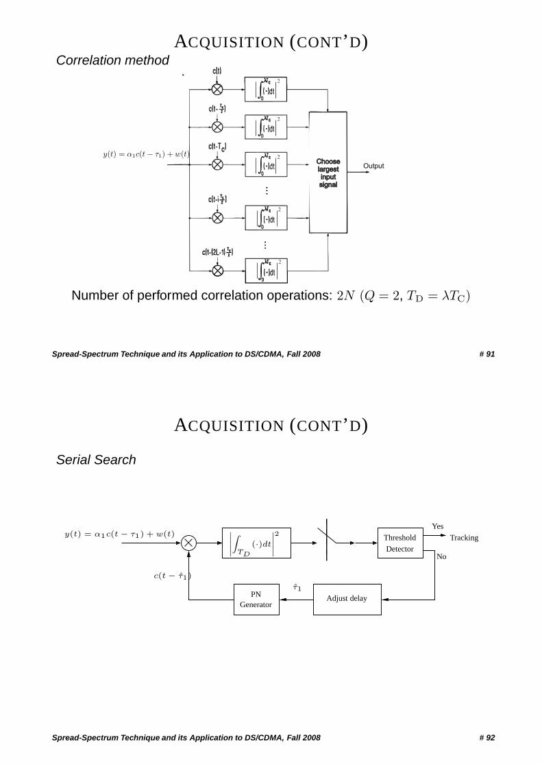
ACQUISITION (CONT’D)Correlation method
Chooselargestinputsignal
Chooselargestinputsignal
Output
2
2
2
2
2
y(t) = α1c(t − τ1) + w(t)
Number of performed correlation operations: 2N (Q = 2, TD = λTC)
Spread-Spectrum Technique and its Application to DS/CDMA, Fall 2008 # 91
ACQUISITION (CONT’D)
Serial Search
PNGenerator
Threshold
Detector
Yes
No
Tracking
Adjust delay
˛˛˛Z
TD
(·)dt
˛˛˛2y(t) = α1c(t − τ1) + w(t)
c(t − τ1)
τ1
Spread-Spectrum Technique and its Application to DS/CDMA, Fall 2008 # 92
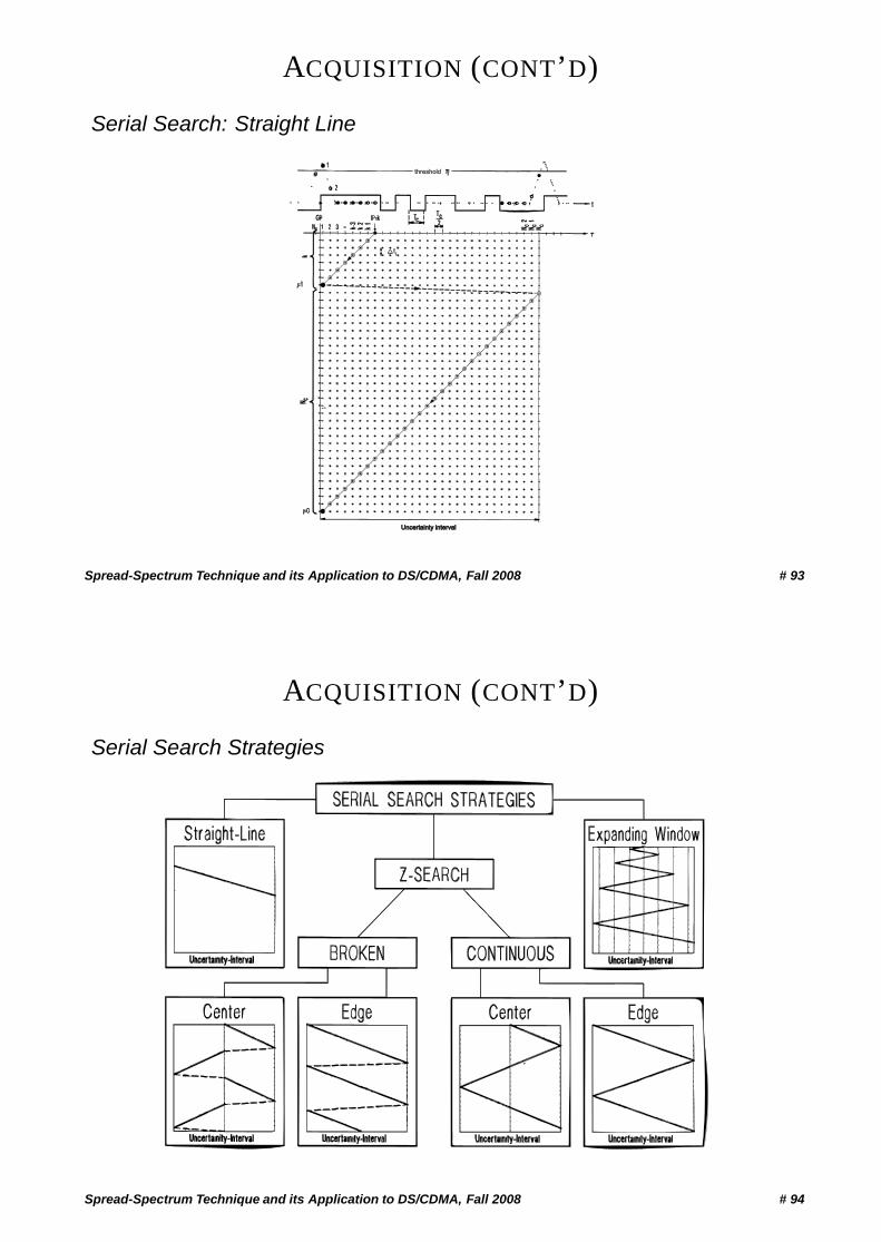
ACQUISITION (CONT’D)
Serial Search: Straight Line
threshold
Uncertainty intervalUncertainty interval
Spread-Spectrum Technique and its Application to DS/CDMA, Fall 2008 # 93
ACQUISITION (CONT’D)
Serial Search Strategies
Spread-Spectrum Technique and its Application to DS/CDMA, Fall 2008 # 94
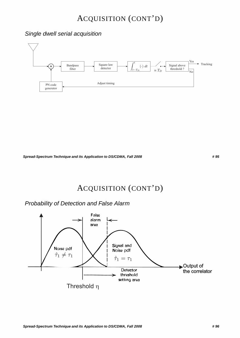
ACQUISITION (CONT’D)
Single dwell serial acquisition
+Square law
detectorBandpass
filterSignal abovethreshold ?
PN codegenerator
Adjust timing
Yes
No
Tracking∫ t
t−TD
(·) dtn TD
Spread-Spectrum Technique and its Application to DS/CDMA, Fall 2008 # 95
ACQUISITION (CONT’D)
Probability of Detection and False Alarm
Output ofthe correlatorOutput ofthe correlator
Threshold �
τ1 = τ1 τ1 = τ1
Spread-Spectrum Technique and its Application to DS/CDMA, Fall 2008 # 96
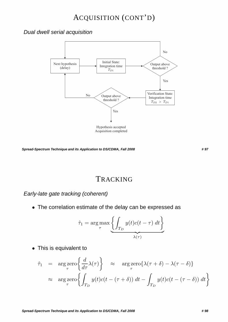
ACQUISITION (CONT’D)
Dual dwell serial acquisition
Next hypothesis(delay)
Initial State:Integration time
Verification State:Integration time
Output abovethreshold ?
Output abovethreshold ?
Yes
No
No
Yes
Hypothesis acceptedAcquisition completed
TD1
TD2 > TD1
Spread-Spectrum Technique and its Application to DS/CDMA, Fall 2008 # 97
TRACKING
Early-late gate tracking (coherent)
• The correlation estimate of the delay can be expressed as
τ1 = arg maxτ
{∫TD
y(t)c(t − τ ) dt
}︸ ︷︷ ︸
λ(τ)
• This is equivalent to
τ1 = arg zeroτ
{d
dτλ(τ )
}≈ arg zero
τ{λ(τ + δ) − λ(τ − δ)}
≈ arg zeroτ
{∫TD
y(t)c(t − (τ + δ)) dt −∫
TD
y(t)c(t − (τ − δ)) dt
}
Spread-Spectrum Technique and its Application to DS/CDMA, Fall 2008 # 98
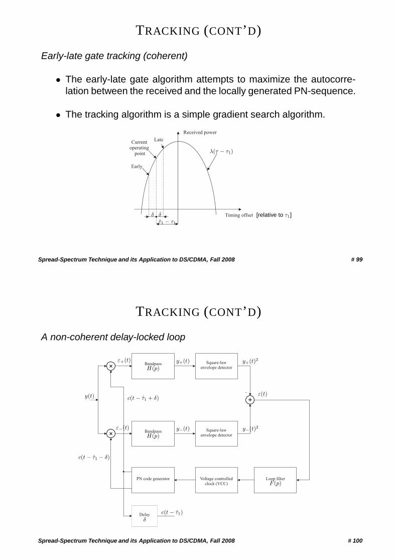
TRACKING (CONT’D)
Early-late gate tracking (coherent)
• The early-late gate algorithm attempts to maximize the autocorre-lation between the received and the locally generated PN-sequence.
• The tracking algorithm is a simple gradient search algorithm.
Received power
Timing offset
Early
Currentoperating
point
Late
λ(τ − τ1)
δδτ1 − τ1
[relative to τ1]
Spread-Spectrum Technique and its Application to DS/CDMA, Fall 2008 # 99
TRACKING (CONT’D)
A non-coherent delay-locked loop
+
+
+
Bandpass
Bandpass
Square-lawenvelope detector
Square-lawenvelope detector
-
Loop filterVoltage controlledclock (VCC)
PN code generator
Delay
y(t)
H(p)
H(p)
ε(t)
F (p)
ε+(t)
c(t − τ1 − δ)
ε−(t)
δ
c(t − τ1)
c(t − τ1 + δ)
y+(t)
y−(t)
y+(t)2
y−(t)2
Spread-Spectrum Technique and its Application to DS/CDMA, Fall 2008 # 100
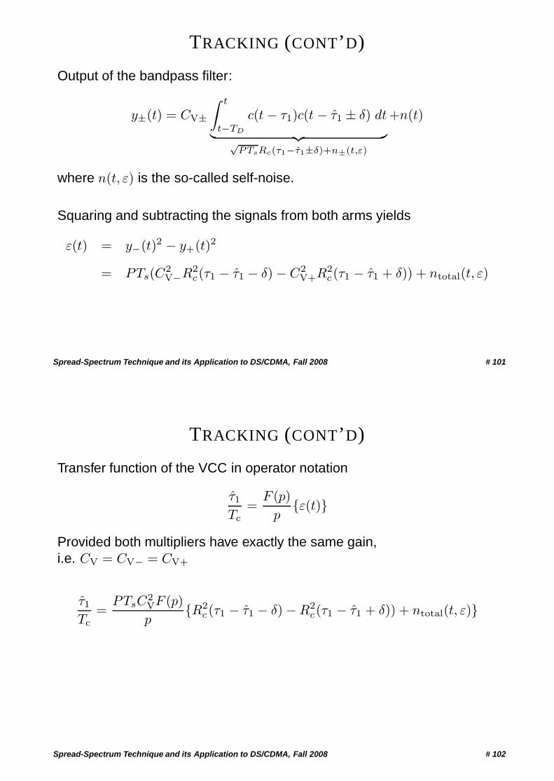
TRACKING (CONT’D)
Output of the bandpass filter:
y±(t) = CV±∫ t
t−TD
c(t − τ1)c(t − τ1 ± δ) dt︸ ︷︷ ︸√PTsRc(τ1−τ1±δ)+n±(t,ε)
+n(t)
where n(t, ε) is the so-called self-noise.
Squaring and subtracting the signals from both arms yields
ε(t) = y−(t)2 − y+(t)2
= PTs(C2V−R2
c(τ1 − τ1 − δ) − C2V+R2
c(τ1 − τ1 + δ)) + ntotal(t, ε)
Spread-Spectrum Technique and its Application to DS/CDMA, Fall 2008 # 101
TRACKING (CONT’D)
Transfer function of the VCC in operator notation
τ1
Tc=
F (p)p
{ε(t)}
Provided both multipliers have exactly the same gain,i.e. CV = CV− = CV+
τ1
Tc=
PTsC2VF (p)p
{R2c(τ1 − τ1 − δ) − R2
c(τ1 − τ1 + δ)) + ntotal(t, ε)}
Spread-Spectrum Technique and its Application to DS/CDMA, Fall 2008 # 102
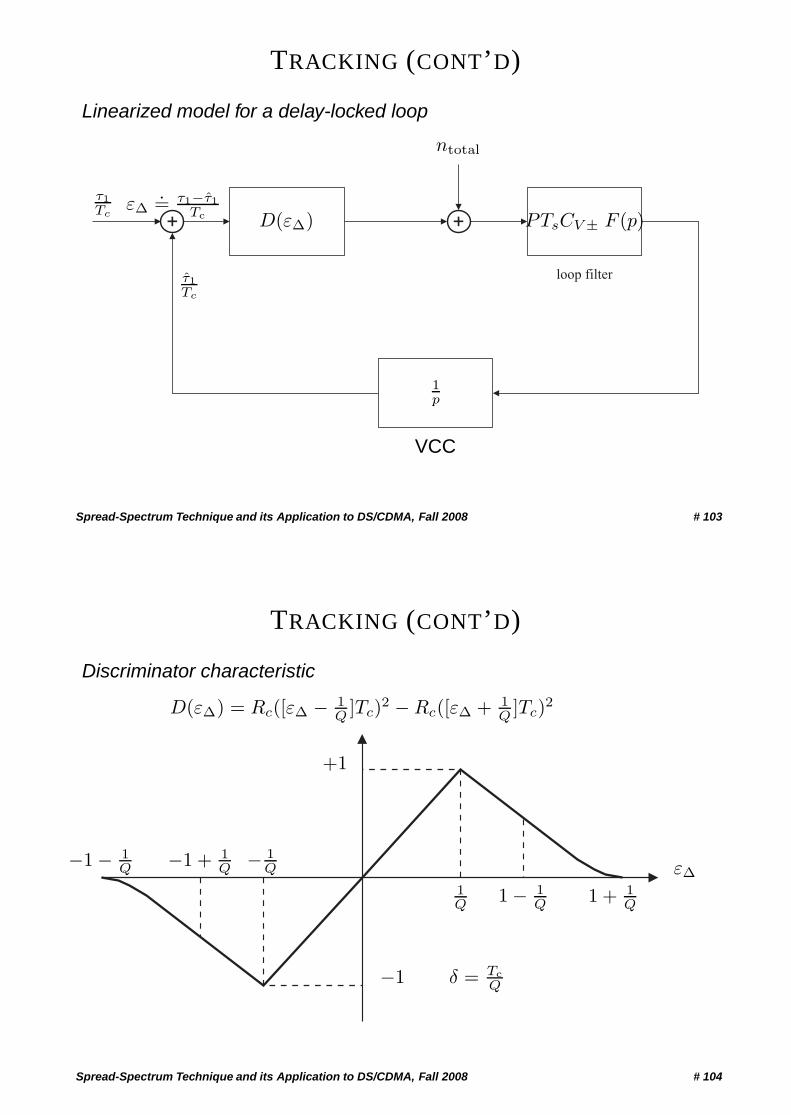
TRACKING (CONT’D)
Linearized model for a delay-locked loop
+ +
loop filter
τ1Tc
εΔ.= τ1−τ1
Tc D(εΔ)
ntotal
PTsCV ± F (p)
1p
τ1Tc
VCC
Spread-Spectrum Technique and its Application to DS/CDMA, Fall 2008 # 103
TRACKING (CONT’D)
Discriminator characteristic
−1 − 1Q −1 + 1
Q − 1Q
−1 δ = TcQ
+1
D(εΔ) = Rc([εΔ − 1Q ]Tc)2 − Rc([εΔ + 1
Q ]Tc)2
1Q
1 − 1Q 1 + 1
Q
εΔ
Spread-Spectrum Technique and its Application to DS/CDMA, Fall 2008 # 104
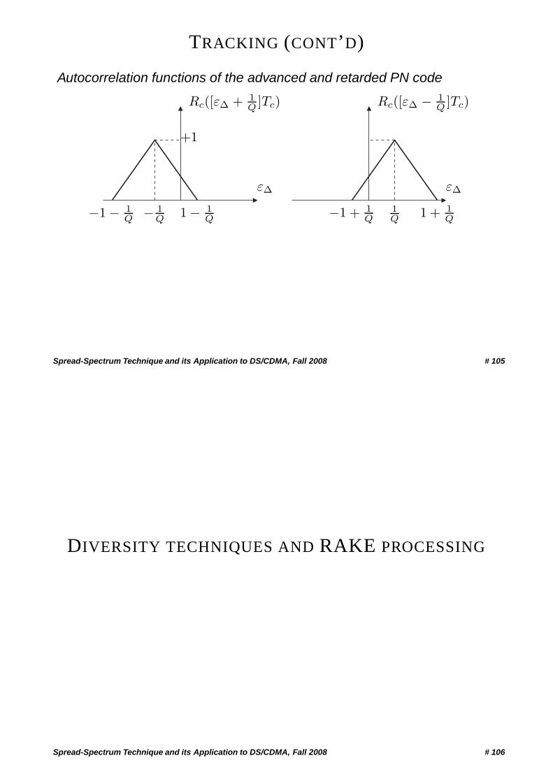
TRACKING (CONT’D)
Autocorrelation functions of the advanced and retarded PN code
−1 − 1Q −1 + 1
Q− 1Q
+1
1Q
1 − 1Q 1 + 1
Q
εΔ εΔ
Rc([εΔ + 1Q ]Tc) Rc([εΔ − 1
Q ]Tc)
Spread-Spectrum Technique and its Application to DS/CDMA, Fall 2008 # 105
DIVERSITY TECHNIQUES AND RAKE PROCESSING
Spread-Spectrum Technique and its Application to DS/CDMA, Fall 2008 # 106
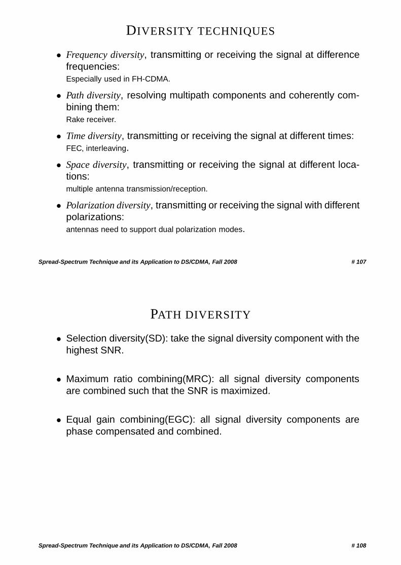
DIVERSITY TECHNIQUES
• Frequency diversity, transmitting or receiving the signal at differencefrequencies:Especially used in FH-CDMA.
• Path diversity, resolving multipath components and coherently com-bining them:Rake receiver.
• Time diversity, transmitting or receiving the signal at different times:FEC, interleaving.
• Space diversity, transmitting or receiving the signal at different loca-tions:multiple antenna transmission/reception.
• Polarization diversity, transmitting or receiving the signal with differentpolarizations:antennas need to support dual polarization modes.
Spread-Spectrum Technique and its Application to DS/CDMA, Fall 2008 # 107
PATH DIVERSITY
• Selection diversity(SD): take the signal diversity component with thehighest SNR.
• Maximum ratio combining(MRC): all signal diversity componentsare combined such that the SNR is maximized.
• Equal gain combining(EGC): all signal diversity components arephase compensated and combined.
Spread-Spectrum Technique and its Application to DS/CDMA, Fall 2008 # 108
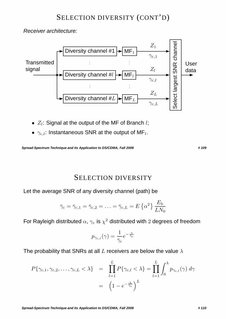
SELECTION DIVERSITY (CONT’D)
Receiver architecture:
Transmittedsignal
Diversity channel #1
Diversity channel #l
Diversity channel #L
MF1
MFl
MFL
Sel
ectl
arge
stS
NR
chan
nel
Z1
γc,1
Zl
γc,l
ZL
γc,L
Userdata
• Zl: Signal at the output of the MF of Branch l;
• γc,l: Instantaneous SNR at the output of MFl.
Spread-Spectrum Technique and its Application to DS/CDMA, Fall 2008 # 109
SELECTION DIVERSITY
Let the average SNR of any diversity channel (path) be
γc = γc,1 = γc,2 = . . . = γc,L = E{α2} Eb
LN0
For Rayleigh distributed α, γc is χ2 distributed with 2 degrees of freedom
pγc,l(γ) =
1γc
e−γγc
The probability that SNRs at all L receivers are below the value λ
P{γc,1, γc,2, . . . , γc,L < λ} =L∏
l=1
P{γc,l < λ} =L∏
l=1
∫ λ
0
pγc,l(γ) dγ
=(1 − e−
λγc
)L
Spread-Spectrum Technique and its Application to DS/CDMA, Fall 2008 # 110
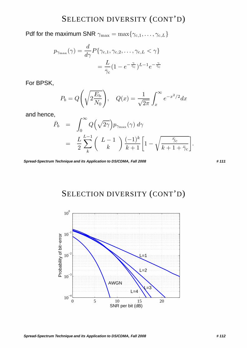
SELECTION DIVERSITY (CONT’D)
Pdf for the maximum SNR γmax = max{γc,1, . . . , γc,L}
pγmax(γ) =d
dγP{γc,1, γc,2, . . . , γc,L < γ}
=L
γc(1 − e−
γγc )L−1e−
γγc
For BPSK,
Pb = Q
(√2Eb
N0
), Q(x) =
1√2π
∫ ∞
x
e−x2/2dx
and hence,
Pb =∫ ∞
0
Q(√
2γ)pγmax (γ) dγ
=L
2
L−1∑k
(L − 1
k
)(−1)k
k + 1
[1 −
√γc
k + 1 + γc
].
Spread-Spectrum Technique and its Application to DS/CDMA, Fall 2008 # 111
SELECTION DIVERSITY (CONT’D)
0 5 10 15 2010
−4
10−3
10−2
10−1
100
L=1
L=2
L=3L=4
AWGN
SNR per bit (dB)
Pro
babi
lity
of b
it−er
ror
Spread-Spectrum Technique and its Application to DS/CDMA, Fall 2008 # 112
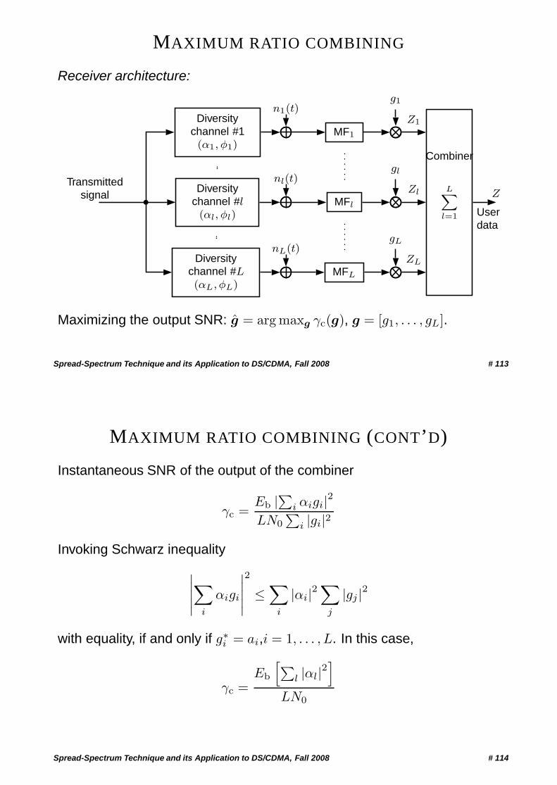
MAXIMUM RATIO COMBINING
Receiver architecture:
Transmittedsignal
Diversitychannel #1(α1, φ1)
Diversitychannel #l(αl, φl)
Diversitychannel #L(αL, φL)
n1(t)
nl(t)
nL(t)
g1
gl
gL
MF1
MFl
MFL
LX
l=1
Combiner
Z1
Zl
ZL
Z
Userdata
Maximizing the output SNR: g = arg maxg γc(g), g = [g1, . . . , gL].
Spread-Spectrum Technique and its Application to DS/CDMA, Fall 2008 # 113
MAXIMUM RATIO COMBINING (CONT’D)
Instantaneous SNR of the output of the combiner
γc =Eb |∑i αigi|2LN0
∑i |gi|2
Invoking Schwarz inequality∣∣∣∣∣∑i
αigi
∣∣∣∣∣2
≤∑
i
|αi|2∑
j
|gj |2
with equality, if and only if g∗i = ai,i = 1, . . . , L. In this case,
γc =Eb
[∑l |αl|2
]LN0
Spread-Spectrum Technique and its Application to DS/CDMA, Fall 2008 # 114
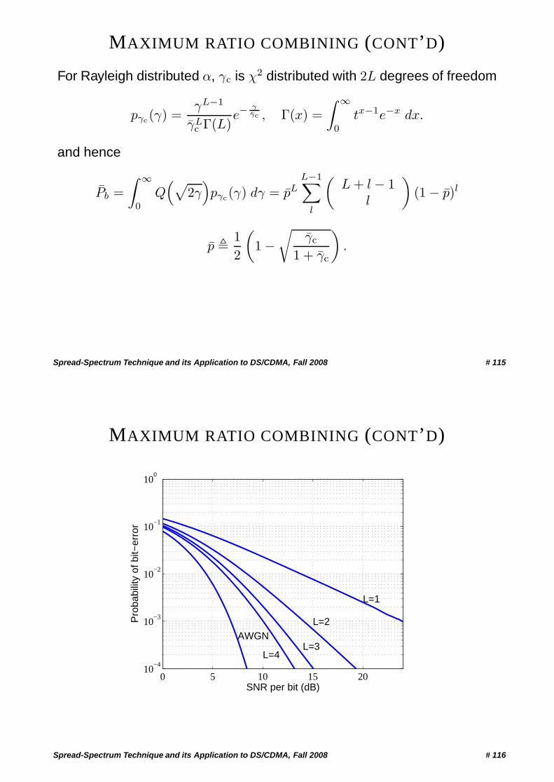
MAXIMUM RATIO COMBINING (CONT’D)
For Rayleigh distributed α, γc is χ2 distributed with 2L degrees of freedom
pγc(γ) =γL−1
γLc Γ(L)
e−γγc , Γ(x) =
∫ ∞
0
tx−1e−x dx.
and hence
Pb =∫ ∞
0
Q(√
2γ)pγc(γ) dγ = pL
L−1∑l
(L + l − 1
l
)(1 − p)l
p � 12
(1 −
√γc
1 + γc
).
Spread-Spectrum Technique and its Application to DS/CDMA, Fall 2008 # 115
MAXIMUM RATIO COMBINING (CONT’D)
0 5 10 15 2010
−4
10−3
10−2
10−1
100
L=1
L=2
L=3L=4
AWGN
SNR per bit (dB)
Pro
babi
lity
of b
it−er
ror
Spread-Spectrum Technique and its Application to DS/CDMA, Fall 2008 # 116
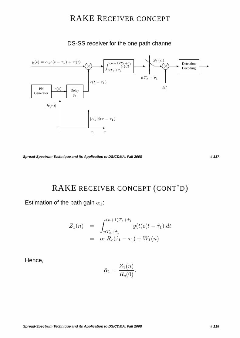
RAKE RECEIVER CONCEPT
DS-SS receiver for the one path channel
PNGenerator
DetectionDecoding
Delay
c(t − τ1)
c(t)
|h(τ)|
nTs + τ1
τ1 τ
|α1|δ(τ − τ1)
τ1
α∗1
Z (n+1)Ts+τ1
nTs+τ1(·)dt
y(t) = α1c(t − τ1) + w(t) Z1(n)
Spread-Spectrum Technique and its Application to DS/CDMA, Fall 2008 # 117
RAKE RECEIVER CONCEPT (CONT’D)
Estimation of the path gain α1:
Z1(n) =∫ (n+1)Ts+τ1
nTs+τ1
y(t)c(t − τ1) dt
= α1Rc(τ1 − τ1) + W1(n)
Hence,
α1 =Z1(n)Rc(0)
.
Spread-Spectrum Technique and its Application to DS/CDMA, Fall 2008 # 118
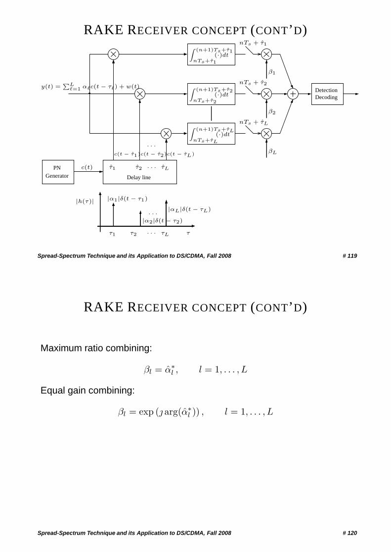
RAKE RECEIVER CONCEPT (CONT’D)
PNGenerator
DetectionDecoding
Z (n+1)Ts+τ1
nTs+τ1(·)dt
Z (n+1)Ts+τL
nTs+τL
(·)dt
Z (n+1)Ts+τ2
nTs+τ2(·)dt
τLτ2τ1
Delay line
c(t)
|αL|δ(t − τL)
τ
β1
β2
βL
|α1|δ(t − τ1)
c(t − τ1)c(t − τ2)c(t − τL)
|h(τ)|
τ1 τ2 τL
nTs + τ1
nTs + τ2
nTs + τL
|α2|δ(t − τ2)
· · ·
· · ·
· · ·
· · ·
y(t) =PL
�=1 α�c(t − τ�) + w(t)
Spread-Spectrum Technique and its Application to DS/CDMA, Fall 2008 # 119
RAKE RECEIVER CONCEPT (CONT’D)
Maximum ratio combining:
βl = α∗l , l = 1, . . . , L
Equal gain combining:
βl = exp (j arg(α∗l )) , l = 1, . . . , L
Spread-Spectrum Technique and its Application to DS/CDMA, Fall 2008 # 120
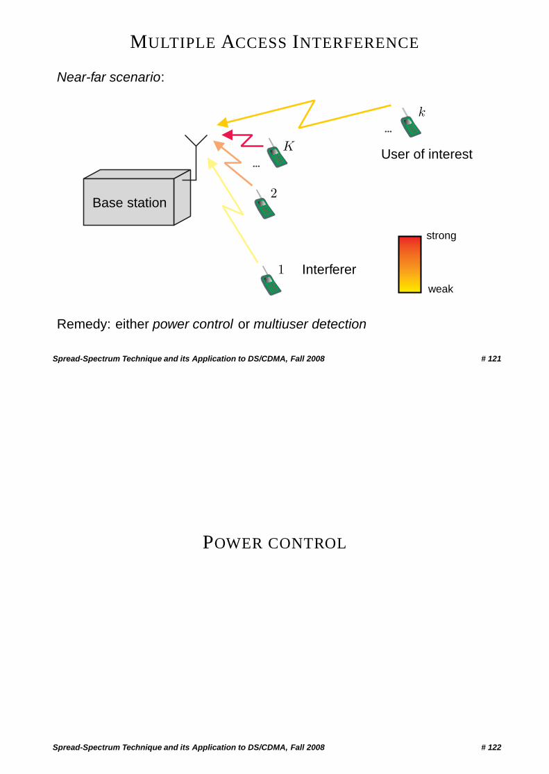
MULTIPLE ACCESS INTERFERENCE
Near-far scenario:
…
…
Base station
K
k
1
2
User of interest
Interfererweak
strong
Remedy: either power control or multiuser detection
Spread-Spectrum Technique and its Application to DS/CDMA, Fall 2008 # 121
POWER CONTROL
Spread-Spectrum Technique and its Application to DS/CDMA, Fall 2008 # 122
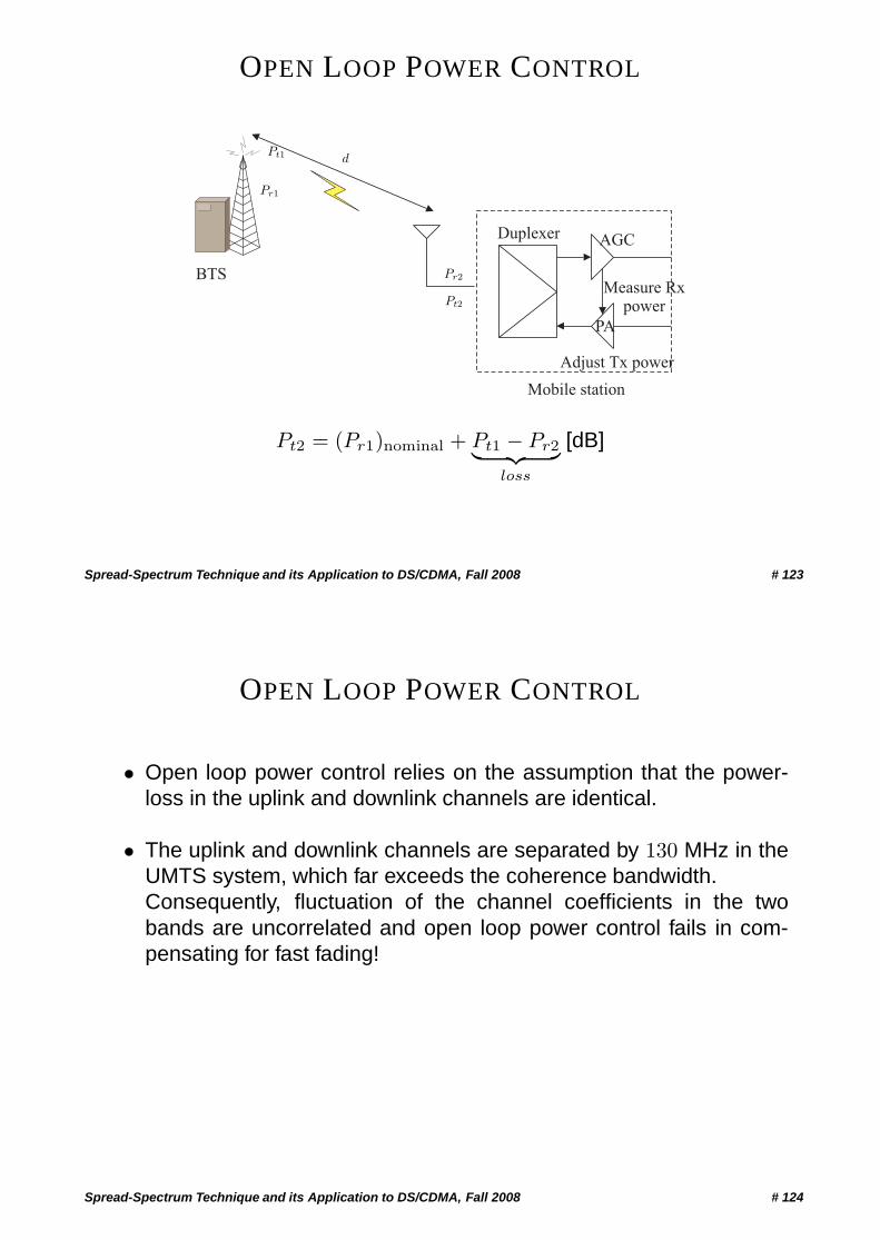
OPEN LOOP POWER CONTROL
Duplexer AGC
Measure Rxpower
Adjust Tx power
PA
Mobile station
BTS
Pr1
Pt1
Pr2
Pt2
d
Pt2 = (Pr1)nominal + Pt1 − Pr2︸ ︷︷ ︸loss
[dB]
Spread-Spectrum Technique and its Application to DS/CDMA, Fall 2008 # 123
OPEN LOOP POWER CONTROL
• Open loop power control relies on the assumption that the power-loss in the uplink and downlink channels are identical.
• The uplink and downlink channels are separated by 130 MHz in theUMTS system, which far exceeds the coherence bandwidth.Consequently, fluctuation of the channel coefficients in the twobands are uncorrelated and open loop power control fails in com-pensating for fast fading!
Spread-Spectrum Technique and its Application to DS/CDMA, Fall 2008 # 124
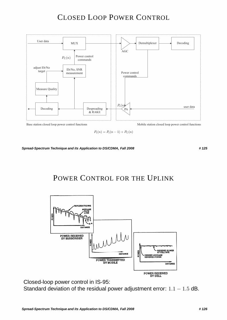
CLOSED LOOP POWER CONTROL
User dataMUX
Eb/No, SNRmeasurement
Power controlcommands
adjust Eb/Notarget
Measure Quality
Decoding Despreading& RAKE
PA
AGC
Demultiplexer Decoding
Power controlcommands
user data
Base station closed loop power control functions Mobile station closed loop power control functions
Pt(n)
Pt(n) = Pt(n − 1) + PC(n)
PC(n)
Spread-Spectrum Technique and its Application to DS/CDMA, Fall 2008 # 125
POWER CONTROL FOR THE UPLINK
Closed-loop power control in IS-95:Standard deviation of the residual power adjustment error: 1.1 − 1.5 dB.
Spread-Spectrum Technique and its Application to DS/CDMA, Fall 2008 # 126
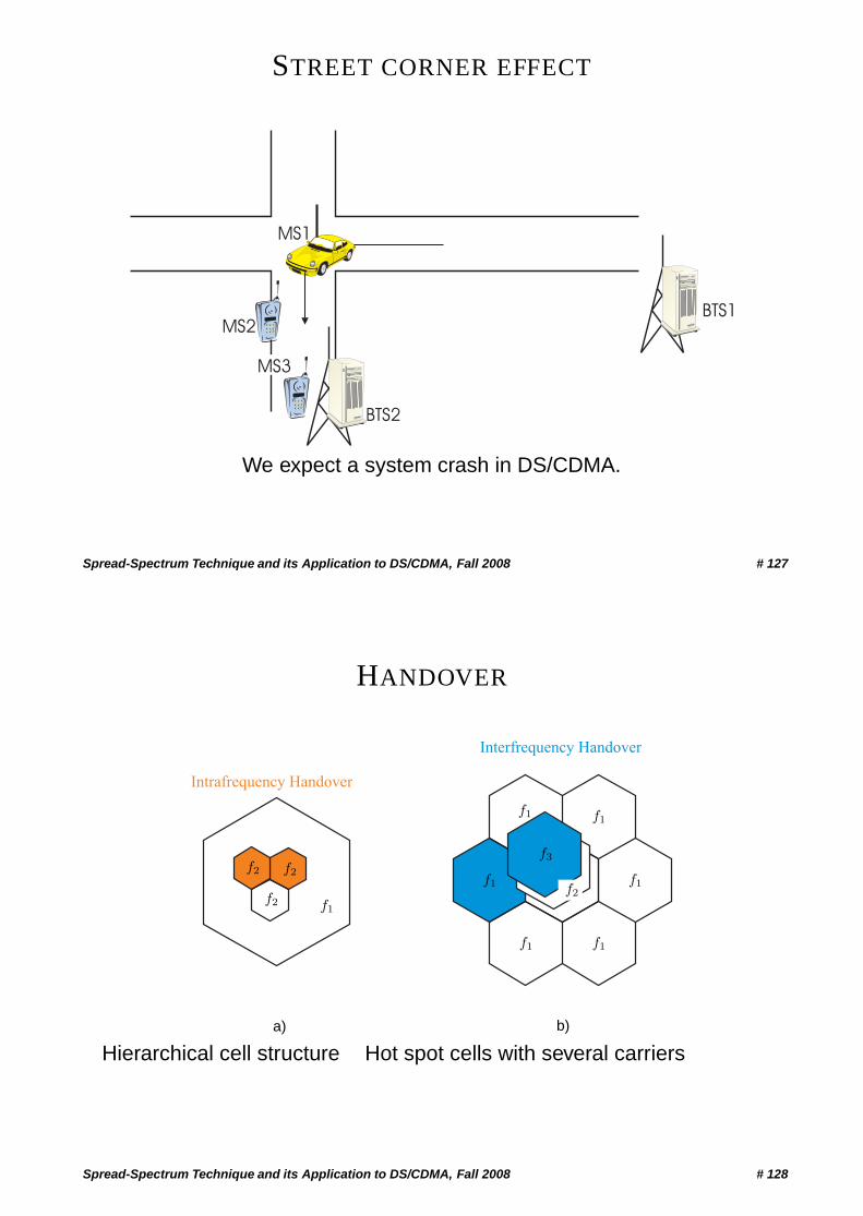
STREET CORNER EFFECT
BTS1
BTS2
MS1
MS2
MS3
We expect a system crash in DS/CDMA.
Spread-Spectrum Technique and its Application to DS/CDMA, Fall 2008 # 127
HANDOVER
Intrafrequency Handover
Interfrequency Handover
f1
f1
f1 f1
f1
f1
f1
f2f2
f2f2
f3
a) b)
Hierarchical cell structure Hot spot cells with several carriers
Spread-Spectrum Technique and its Application to DS/CDMA, Fall 2008 # 128
INTRAFREQUENCY HANDOVER
• The MS is connected to two BS at the same time.
• Separate pilot channel used for signal strength measurements.
• Handover is initiated if signal becomes smaller than a certainthreshold.
• Drawback: This 2nd BS causes additional interference, because dif-ferent cells use different scrambling codes.
Spread-Spectrum Technique and its Application to DS/CDMA, Fall 2008 # 129
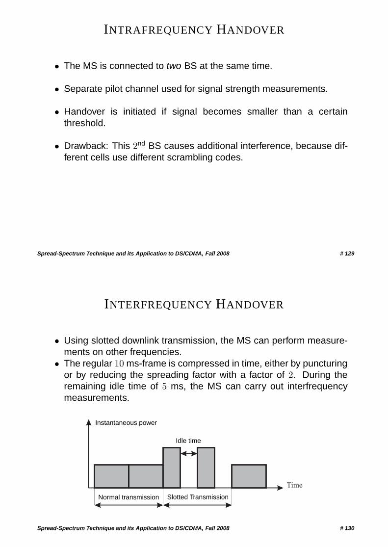
INTERFREQUENCY HANDOVER
• Using slotted downlink transmission, the MS can perform measure-ments on other frequencies.
• The regular 10 ms-frame is compressed in time, either by puncturingor by reducing the spreading factor with a factor of 2. During theremaining idle time of 5 ms, the MS can carry out interfrequencymeasurements.
Time
Instantaneous power
Normal transmission Slotted Transmission
Idle time
Spread-Spectrum Technique and its Application to DS/CDMA, Fall 2008 # 130
UMTS W-CDMA
Spread-Spectrum Technique and its Application to DS/CDMA, Fall 2008 # 131
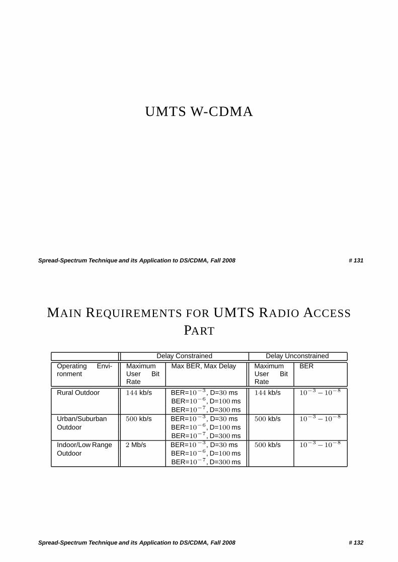
MAIN REQUIREMENTS FOR UMTS RADIO ACCESS
PART
Delay Constrained Delay Unconstrained
Operating Envi-ronment
MaximumUser BitRate
Max BER, Max Delay MaximumUser BitRate
BER
Rural Outdoor 144 kb/s BER=10−3, D=30 ms 144 kb/s 10−3 −10−8
BER=10−6, D=100 msBER=10−7, D=300 ms
Urban/Suburban 500 kb/s BER=10−3, D=30 ms 500 kb/s 10−3 −10−8
Outdoor BER=10−6, D=100 msBER=10−7, D=300 ms
Indoor/Low Range 2 Mb/s BER=10−3, D=30 ms 500 kb/s 10−3 −10−8
Outdoor BER=10−6, D=100 msBER=10−7, D=300 ms
Spread-Spectrum Technique and its Application to DS/CDMA, Fall 2008 # 132
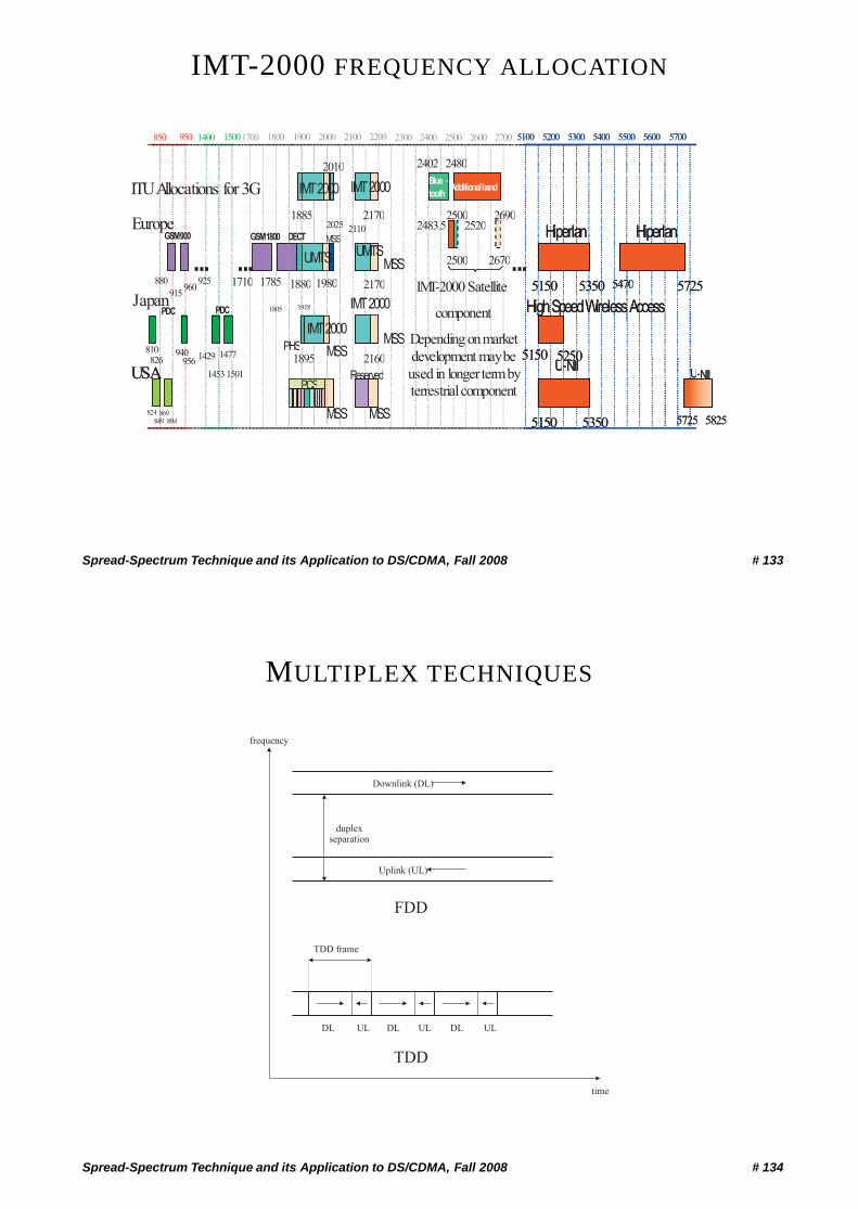
IMT-2000 FREQUENCY ALLOCATION
Spread-Spectrum Technique and its Application to DS/CDMA, Fall 2008 # 133
MULTIPLEX TECHNIQUES
Downlink (DL)
Uplink (UL)
duplexseparation
FDD
DL DL DLUL UL UL
TDD
time
frequency
TDD frame
Spread-Spectrum Technique and its Application to DS/CDMA, Fall 2008 # 134
WIDEBAND CDMA SPECIFICATIONS (FDD,PHYSICAL LAYER)
Multiple access DS-CDMADuplex technique FDDChip rate 3.84 Mchips/sCarrier spacing 5 MHzFrame size 10 msSpreading technique Variable-spreading factor+multi-codeChannel Coding 1/2-1/3 rate convolutional coding
Turbo codingInterleaving Block interleaver with inter-column permutationsModulation QPSK with roll-off factor α = 0.22
Spread-Spectrum Technique and its Application to DS/CDMA, Fall 2008 # 135
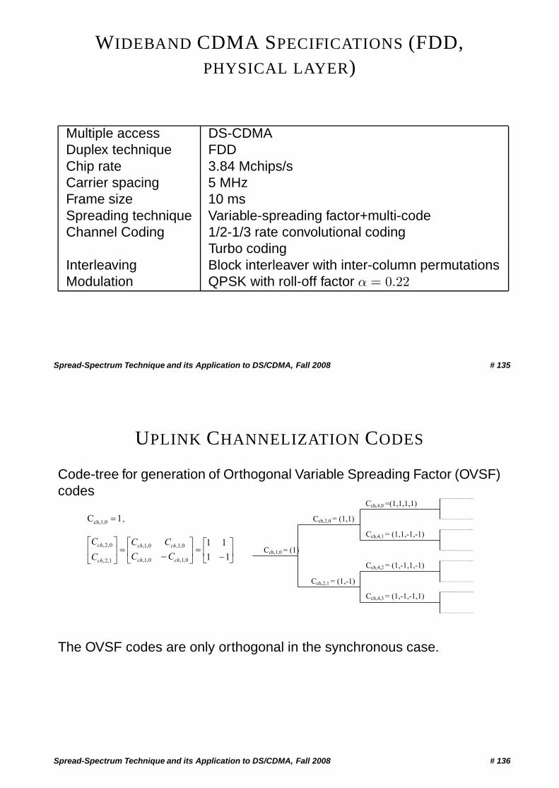
UPLINK CHANNELIZATION CODES
Code-tree for generation of Orthogonal Variable Spreading Factor (OVSF)codes
Cch,1,0 = (1)
Cch,2,0 = (1,1)
Cch,2,1 = (1,-1)
Cch,4,0 =(1,1,1,1)
Cch,4,1 = (1,1,-1,-1)
Cch,4,2 = (1,-1,1,-1)
Cch,4,3 = (1,-1,-1,1)
1Cch,1,0 � ,
��
���
���
���
���
���
11
11
0,1,
0,1,
0,1,
0,1,
1,2,
0,2,
ch
ch
ch
ch
ch
ch
C
C
C
C
C
C
The OVSF codes are only orthogonal in the synchronous case.
Spread-Spectrum Technique and its Application to DS/CDMA, Fall 2008 # 136
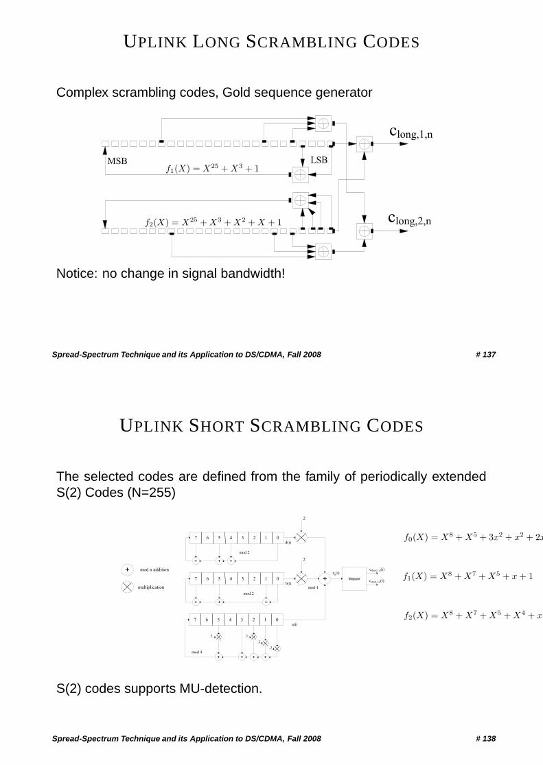
UPLINK LONG SCRAMBLING CODES
Complex scrambling codes, Gold sequence generator
clong,1,n
clong,2,n
MSB LSBf1(X) = X25 + X3 + 1
f2(X) = X25 + X3 + X2 + X + 1
Notice: no change in signal bandwidth!
Spread-Spectrum Technique and its Application to DS/CDMA, Fall 2008 # 137
UPLINK SHORT SCRAMBLING CODES
The selected codes are defined from the family of periodically extendedS(2) Codes (N=255)
07 4
+ mod n addition
d(i)12356
2
mod 2
07 4b(i)
12356
2
mod 2
+mod 4multiplication
zn(i)
07 4 12356
+mod 4
Mapper
cshort,1,n(i)
a(i)
+ + +
+ ++
+ ++
3 3
3
2
cshort,2,n(i)
f0(X) = X8 + X5 + 3x2 + x2 + 2x
f1(X) = X8 + X7 + X5 + x + 1
f2(X) = X8 + X7 + X5 + X4 + x
S(2) codes supports MU-detection.
Spread-Spectrum Technique and its Application to DS/CDMA, Fall 2008 # 138
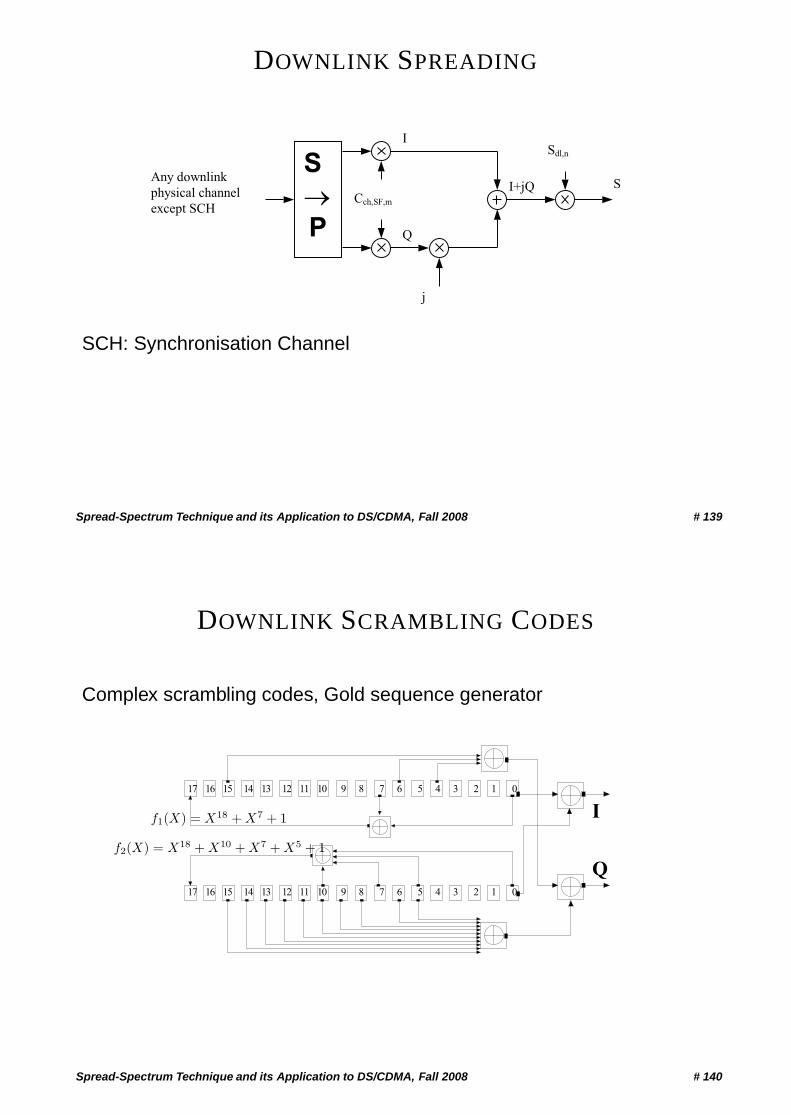
DOWNLINK SPREADING
I
Any downlink
physical channel
except SCH
S
�P
Cch,SF,m
j
Sdl,n
Q
I+jQ S
SCH: Synchronisation Channel
Spread-Spectrum Technique and its Application to DS/CDMA, Fall 2008 # 139
DOWNLINK SCRAMBLING CODES
Complex scrambling codes, Gold sequence generator
I
Q
1
1 0
02
2
3
3
4
4
5
5
6
6
7
7
8
8
9
9
17
17
16
16
15
15
14
14
13
13
12
12
11
11
10
10
f1(X) = X18 + X7 + 1
f2(X) = X18 + X10 + X7 + X5 + 1
Spread-Spectrum Technique and its Application to DS/CDMA, Fall 2008 # 140
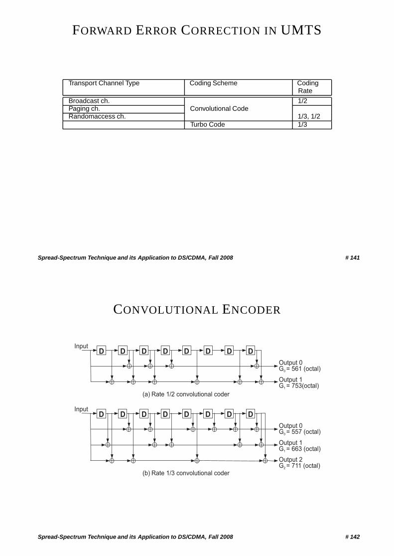
FORWARD ERROR CORRECTION IN UMTS
Transport Channel Type Coding Scheme CodingRate
Broadcast ch. 1/2Paging ch. Convolutional CodeRandomaccess ch. 1/3, 1/2
Turbo Code 1/3
Spread-Spectrum Technique and its Application to DS/CDMA, Fall 2008 # 141
CONVOLUTIONAL ENCODER
Output 0G0 = 557 (octal)
InputD D D D D D D D
Output 1G1 = 663 (octal)
Output 2G2 = 711 (octal)
Output 0G0 = 561 (octal)
InputD D D D D D D D
Output 1G1 = 753(octal)
(a) Rate 1/2 convolutional coder
(b) Rate 1/3 convolutional coder
Spread-Spectrum Technique and its Application to DS/CDMA, Fall 2008 # 142
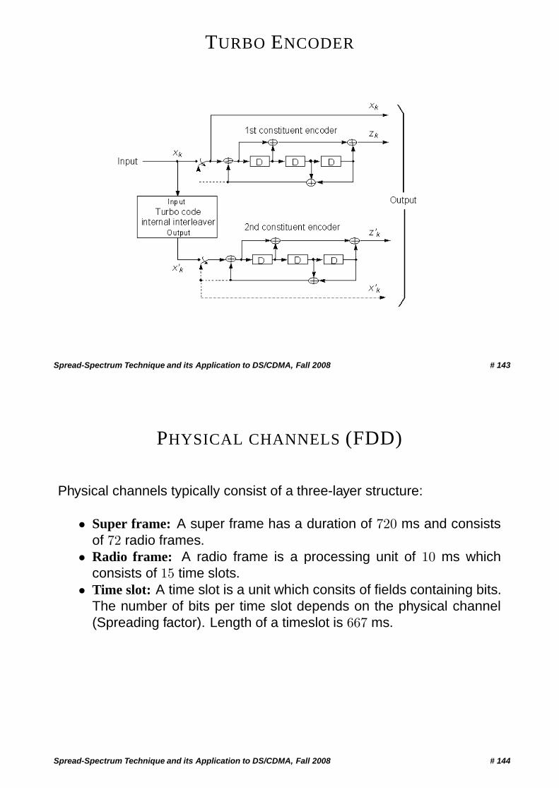
TURBO ENCODER
Spread-Spectrum Technique and its Application to DS/CDMA, Fall 2008 # 143
PHYSICAL CHANNELS (FDD)
Physical channels typically consist of a three-layer structure:
• Super frame: A super frame has a duration of 720 ms and consistsof 72 radio frames.
• Radio frame: A radio frame is a processing unit of 10 ms whichconsists of 15 time slots.
• Time slot: A time slot is a unit which consits of fields containing bits.The number of bits per time slot depends on the physical channel(Spreading factor). Length of a timeslot is 667 ms.
Spread-Spectrum Technique and its Application to DS/CDMA, Fall 2008 # 144
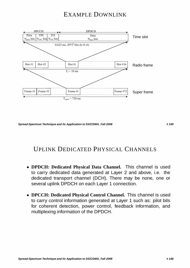
EXAMPLE DOWNLINK
TPC
NTPC bits
Slot #1 Slot #2 Slot #i Slot #16
Frame #1 Frame #2 Frame #i Frame #72
0.625 ms, 20*2k
bits (k=0..6)
Pilot
Npilot bitsData
Ndata bits
DPCCH DPDCH
Tf = 10 ms
Tsuper = 720 ms
TFI
NTFI bitsTime slot
Radio frame
Super frame
Spread-Spectrum Technique and its Application to DS/CDMA, Fall 2008 # 145
UPLINK DEDICATED PHYSICAL CHANNELS
• DPDCH: Dedicated Physical Data Channel. This channel is usedto carry dedicated data generated at Layer 2 and above, i.e. thededicated transport channel (DCH). There may be none, one orseveral uplink DPDCH on each Layer 1 connection.
• DPCCH: Dedicated Physical Control Channel. This channel is usedto carry control information generated at Layer 1 such as: pilot bitsfor coherent detection, power control, feedback information, andmultiplexing information of the DPDCH.
Spread-Spectrum Technique and its Application to DS/CDMA, Fall 2008 # 146
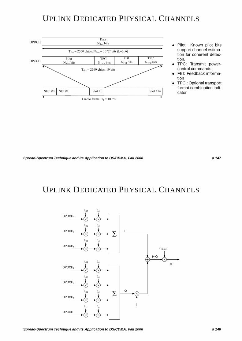
UPLINK DEDICATED PHYSICAL CHANNELS
Pilot
Npilot bits
TPC
NTPC bits
Data
Ndata bits
Slot #0 Slot #1 Slot #i Slot #14
Tslot = 2560 chips, 10 bits
1 radio frame: Tf = 10 ms
DPDCH
DPCCHFBI
NFBI bitsTFCI
NTFCI bits
Tslot = 2560 chips, Ndata = 10*2k
bits (k=0..6)
• Pilot: Known pilot bitssupport channel estima-tion for coherent detec-tion.
• TPC: Transmit power-control commands
• FBI: Feedback informa-tion
• TFCI: Optional transportformat combination indi-cator
Spread-Spectrum Technique and its Application to DS/CDMA, Fall 2008 # 147
UPLINK DEDICATED PHYSICAL CHANNELS
I
�
j
cd,1 d
Sdpch,n
I+jQ
DPDCH1
Q
cd,3 d
DPDCH3
cd,5 d
DPDCH5
cd,2 d
DPDCH2
cd,4 d
DPDCH4
cd,6 d
DPDCH6
cc c
DPCCH
�
S
Spread-Spectrum Technique and its Application to DS/CDMA, Fall 2008 # 148
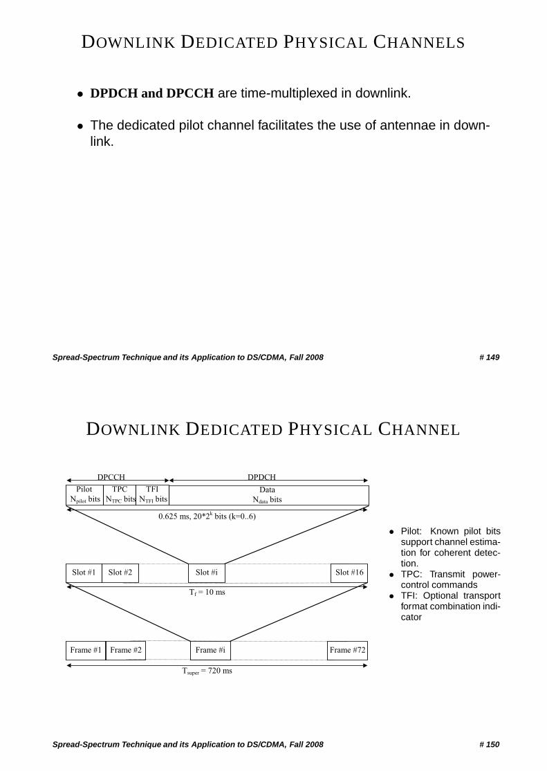
DOWNLINK DEDICATED PHYSICAL CHANNELS
• DPDCH and DPCCH are time-multiplexed in downlink.
• The dedicated pilot channel facilitates the use of antennae in down-link.
Spread-Spectrum Technique and its Application to DS/CDMA, Fall 2008 # 149
DOWNLINK DEDICATED PHYSICAL CHANNEL
TPC
NTPC bits
Slot #1 Slot #2 Slot #i Slot #16
Frame #1 Frame #2 Frame #i Frame #72
0.625 ms, 20*2k
bits (k=0..6)
Pilot
Npilot bitsData
Ndata bits
DPCCH DPDCH
Tf = 10 ms
Tsuper = 720 ms
TFI
NTFI bits
• Pilot: Known pilot bitssupport channel estima-tion for coherent detec-tion.
• TPC: Transmit power-control commands
• TFI: Optional transportformat combination indi-cator
Spread-Spectrum Technique and its Application to DS/CDMA, Fall 2008 # 150
SYNCHRONISATION IN UMTS
The initial Cell Search is carried out in three steps:
• Slot synchronisation using the primary synchronisation channel.
• Frame synchronisation and code-group identification – using thesecondary synchronisation channel.
• Scrambling-code identification through symbol-by-symbol correla-tion over the primary CCPCH with all the scambling codes withinthe code group.
Spread-Spectrum Technique and its Application to DS/CDMA, Fall 2008 # 151
UMTS FDD POWER CONTROL SPECIFICATIONS
• Open loop power control– The downlink power is measured on the CCPCH (Common
Control Physical Channel) before the MS transmits the random-access burst.
– Uplink interference level and required SIR is broadcast on theBCCH
• Closed loop power control– Power control commands are sent every 0.625ms.– The step size is 0.5 − 3.0 dB, and is fixed for each cell.– Target SIR is determined by the outer loop.
• Outer loop power control– The target SIR is determined by radio resource management,
i.e. not a physical layer issue.– The SIR level is adjusted according to a quality estimate (FER,
BER, a.s.o).
Spread-Spectrum Technique and its Application to DS/CDMA, Fall 2008 # 152