Embed Size (px)
Citation preview
Harbor Breeze® is a registered trademark of LF, LLC. All Rights Reserved.
ITEM #0152426015673801586200204925
SPRINGFIELD II CEILING FAN
Español p. 21
1
MODEL #E-BDB52LABZ5BC4NE-BDB52BNK5BC4N
E-BDB52LW5BC4NE-BDB52MBK5BC4N
ATTACH YOUR RECEIPT HERE
Serial Number Purchase Date
Questions, problems, missing parts? Before returning to your retailer, call our customer service department at 1-800-643-0067, 8 a.m. - 6 p.m., EST, Monday - Thursday, 8 a.m. - 5 p.m., EST, Friday.
EB15409Lowes.com/harborbreeze
E124404LISTED
Safety Information ...............................................................................................................2
Package Contents ...............................................................................................................4
Hardware Contents ..........................................................................................................................5
Preparation ..........................................................................................................................5
Initial Installation ..................................................................................................................6
Downrod-Style Fan Mounting ..............................................................................................8
Closemount-Style Fan Mounting .......................................................................................10
Wiring .................................................................................................................................11
Final Installation .................................................................................................................13
Operating Instructions .......................................................................................................16
Care and Maintenance ......................................................................................................18
Troubleshooting..................................................................................................................18
Limited Lifetime Warranty ..................................................................................................19
Replacement Parts List .....................................................................................................20
TABLE OF CONTENTS
2Lowes.com/harborbreeze
READ AND SAVE THESE INSTRUCTIONSPlease read and understand this entire manual before attempting to assemble, install or operate the
product.
• Do not discard fan carton or foam inserts. Should this fan need to be returned to the factory for repairs, it must be shipped in its original packaging to ensure proper protection against damage that might exceed the initial cause for return.
• Make sure all electrical connections comply with local codes, ordinances, the National Electrical Code and ANSI/NFPA 70-1999. Hire a qualified electrician or consult a do-it-yourself wiring handbook if you are unfamiliar with installing electrical wiring.
• Make sure the installation site you choose allows a minimum clearance of 7 ft. from the blades to the floor and at least 30 in. from the end of the blades to any obstruction.
• After you install the fan, make sure all connections are secure to prevent the fan from falling.• The net weight of this fan including the light kit is: 20.72 lbs.
SAFETY INFORMATION
SAFETY INFORMATION
3Lowes.com/harborbreeze
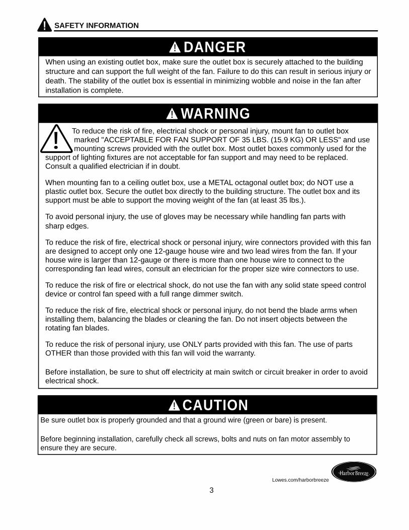
To reduce the risk of fire, electrical shock or personal injury, mount fan to outlet box marked "ACCEPTABLE FOR FAN SUPPORT OF 35 LBS. (15.9 KG) OR LESS" and use mounting screws provided with the outlet box. Most outlet boxes commonly used for the support of lighting fixtures are not acceptable for fan support and may need to be replaced. Consult a qualified electrician if in doubt.
When mounting fan to a ceiling outlet box, use a METAL octagonal outlet box; do NOT use a plastic outlet box. Secure the outlet box directly to the building structure. The outlet box and its support must be able to support the moving weight of the fan (at least 35 lbs.).
To avoid personal injury, the use of gloves may be necessary while handling fan parts with sharp edges.
To reduce the risk of fire, electrical shock or personal injury, wire connectors provided with this fan are designed to accept only one 12-gauge house wire and two lead wires from the fan. If your house wire is larger than 12-gauge or there is more than one house wire to connect to the corresponding fan lead wires, consult an electrician for the proper size wire connectors to use.
To reduce the risk of fire or electrical shock, do not use the fan with any solid state speed control device or control fan speed with a full range dimmer switch.
To reduce the risk of fire, electrical shock or personal injury, do not bend the blade arms when installing them, balancing the blades or cleaning the fan. Do not insert objects between the rotating fan blades.
To reduce the risk of personal injury, use ONLY parts provided with this fan. The use of parts OTHER than those provided with this fan will void the warranty.
Before installation, be sure to shut off electricity at main switch or circuit breaker in order to avoid electrical shock.
WARNING
DANGER
CAUTION
When using an existing outlet box, make sure the outlet box is securely attached to the buildingstructure and can support the full weight of the fan. Failure to do this can result in serious injury ordeath. The stability of the outlet box is essential in minimizing wobble and noise in the fan afterinstallation is complete.
Be sure outlet box is properly grounded and that a ground wire (green or bare) is present.
Before beginning installation, carefully check all screws, bolts and nuts on fan motor assembly to ensure they are secure.
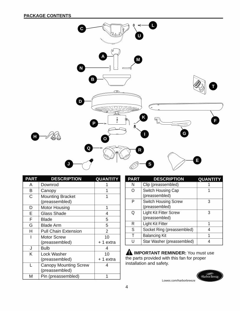
N Clip (preassembled) 1 O Switch Housing Cap 1 (preassembled) P Switch Housing Screw 3 (preassembled) Q Light Kit Fitter Screw 3 (preassembled) R Light Kit Fitter 1 S Socket Ring (preassembled) 4 T Balancing Kit 1 U Star Washer (preassembled) 4
IMPORTANT REMINDER: You must use the parts provided with this fan for proper installation and safety.
PACKAGE CONTENTS
4Lowes.com/harborbreeze
A Downrod 1 B Canopy 1 C Mounting Bracket 1 (preassembled) D Motor Housing 1 E Glass Shade 4 F Blade 5 G Blade Arm 5 H Pull Chain Extension 2 I Motor Screw 10 (preassembled) + 1 extra J Bulb 4 K Lock Washer 10 (preassembled) + 1 extra L Canopy Mounting Screw 4 (preassembled) M Pin (preassembled) 1
DESCRIPTIONPART QUANTITY DESCRIPTIONPART QUANTITY
JE
D
K
L
H
C
I
AM
S
Q
O
P
R
B
N
U
G
F
T
5
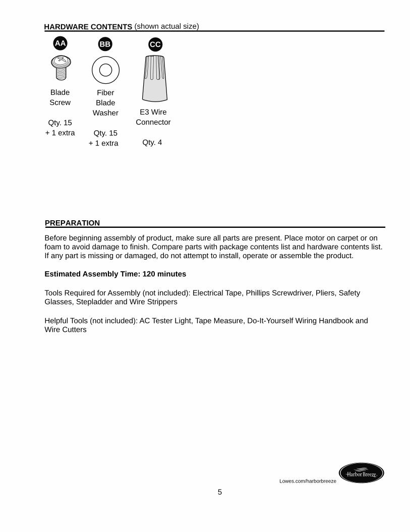
HARDWARE CONTENTS (shown actual size)
Lowes.com/harborbreeze
FiberBlade
Washer
Qty. 15+ 1 extra
CC
BladeScrew
Qty. 15+ 1 extra
E3 WireConnector
Qty. 4
AA BB CC
PREPARATION
Before beginning assembly of product, make sure all parts are present. Place motor on carpet or on foam to avoid damage to finish. Compare parts with package contents list and hardware contents list. If any part is missing or damaged, do not attempt to install, operate or assemble the product.
Estimated Assembly Time: 120 minutes
Tools Required for Assembly (not included): Electrical Tape, Phillips Screwdriver, Pliers, Safety Glasses, Stepladder and Wire Strippers
Helpful Tools (not included): AC Tester Light, Tape Measure, Do-It-Yourself Wiring Handbook and Wire Cutters
6
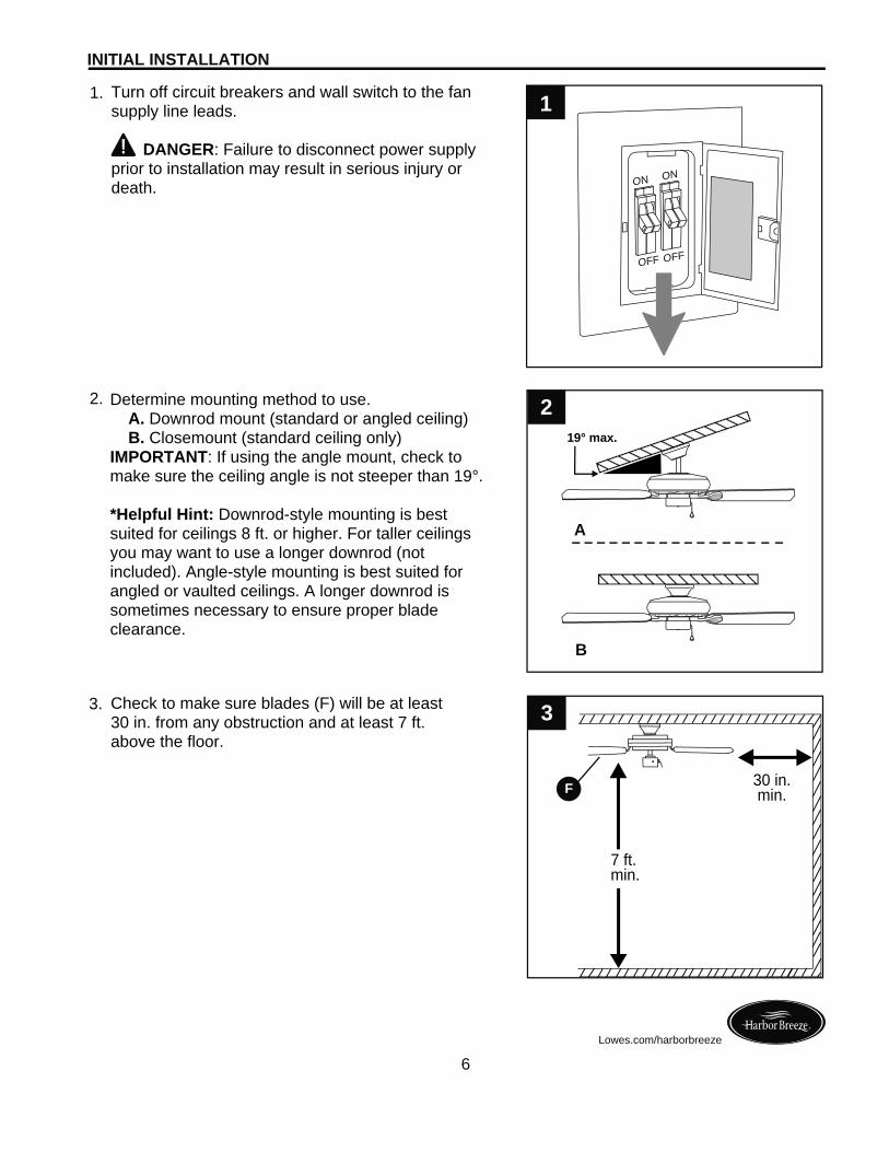
Turn off circuit breakers and wall switch to the fan supply line leads. DANGER: Failure to disconnect power supply prior to installation may result in serious injury or death.
1.
2.
3.
Determine mounting method to use. A. Downrod mount (standard or angled ceiling) B. Closemount (standard ceiling only)IMPORTANT: If using the angle mount, check to make sure the ceiling angle is not steeper than 19°.
*Helpful Hint: Downrod-style mounting is best suited for ceilings 8 ft. or higher. For taller ceilings you may want to use a longer downrod (not included). Angle-style mounting is best suited for angled or vaulted ceilings. A longer downrod is sometimes necessary to ensure proper blade clearance.
7 ft.min.
30 in.min.F
INITIAL INSTALLATION
ON
OFF
ON
OFF
3
1
Lowes.com/harborbreeze
A
B
219° max.
Check to make sure blades (F) will be at least 30 in. from any obstruction and at least 7 ft. above the floor.
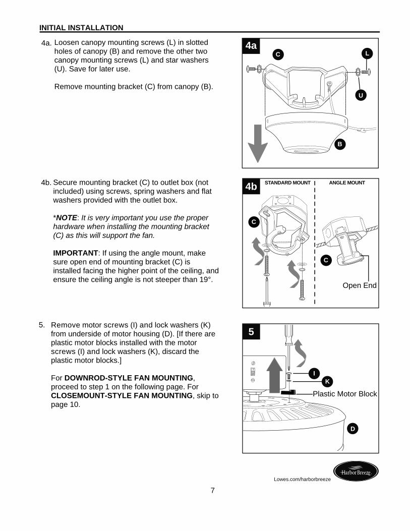
Secure mounting bracket (C) to outlet box (not included) using screws, spring washers and flat washers provided with the outlet box.
*NOTE: It is very important you use the proper hardware when installing the mounting bracket (C) as this will support the fan.
IMPORTANT: If using the angle mount, make sure open end of mounting bracket (C) is installed facing the higher point of the ceiling, and ensure the ceiling angle is not steeper than 19°.
4b.
INITIAL INSTALLATION
7Lowes.com/harborbreeze
5. Remove motor screws (I) and lock washers (K) from underside of motor housing (D). [If there are plastic motor blocks installed with the motor screws (I) and lock washers (K), discard the plastic motor blocks.]
For DOWNROD-STYLE FAN MOUNTING, proceed to step 1 on the following page. For CLOSEMOUNT-STYLE FAN MOUNTING, skip to page 10.
4b
Open End
C
C
ANGLE MOUNTSTANDARD MOUNT
KI
5
D
Plastic Motor Block
4a. Loosen canopy mounting screws (L) in slotted holes of canopy (B) and remove the other two canopy mounting screws (L) and star washers (U). Save for later use.
Remove mounting bracket (C) from canopy (B).
4aC L
B
U
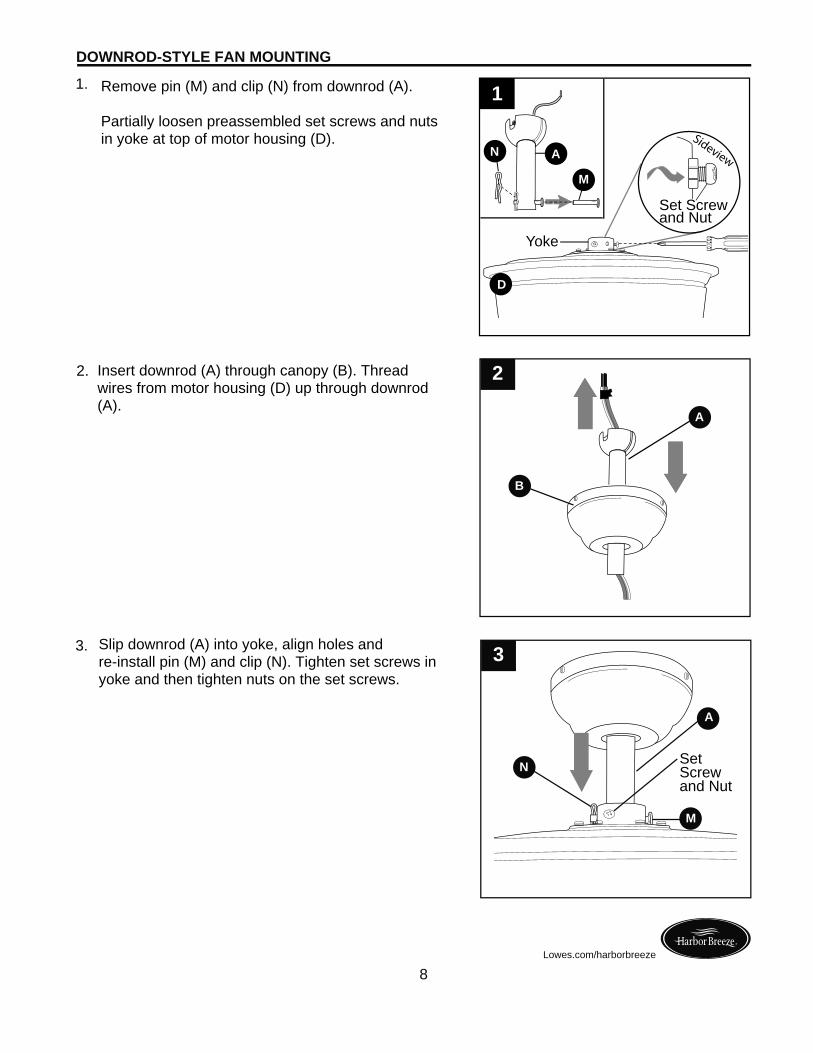
2. Insert downrod (A) through canopy (B). Thread wires from motor housing (D) up through downrod (A).
3.
A
N
M
DOWNROD-STYLE FAN MOUNTING
8
3
Lowes.com/harborbreeze
1.
Slip downrod (A) into yoke, align holes and re-install pin (M) and clip (N). Tighten set screws in yoke and then tighten nuts on the set screws.
SetScrew and Nut
B
A
2
Remove pin (M) and clip (N) from downrod (A).
Partially loosen preassembled set screws and nuts in yoke at top of motor housing (D).
1
N
M
A
Yoke
Set Screwand Nut
Sideview
D
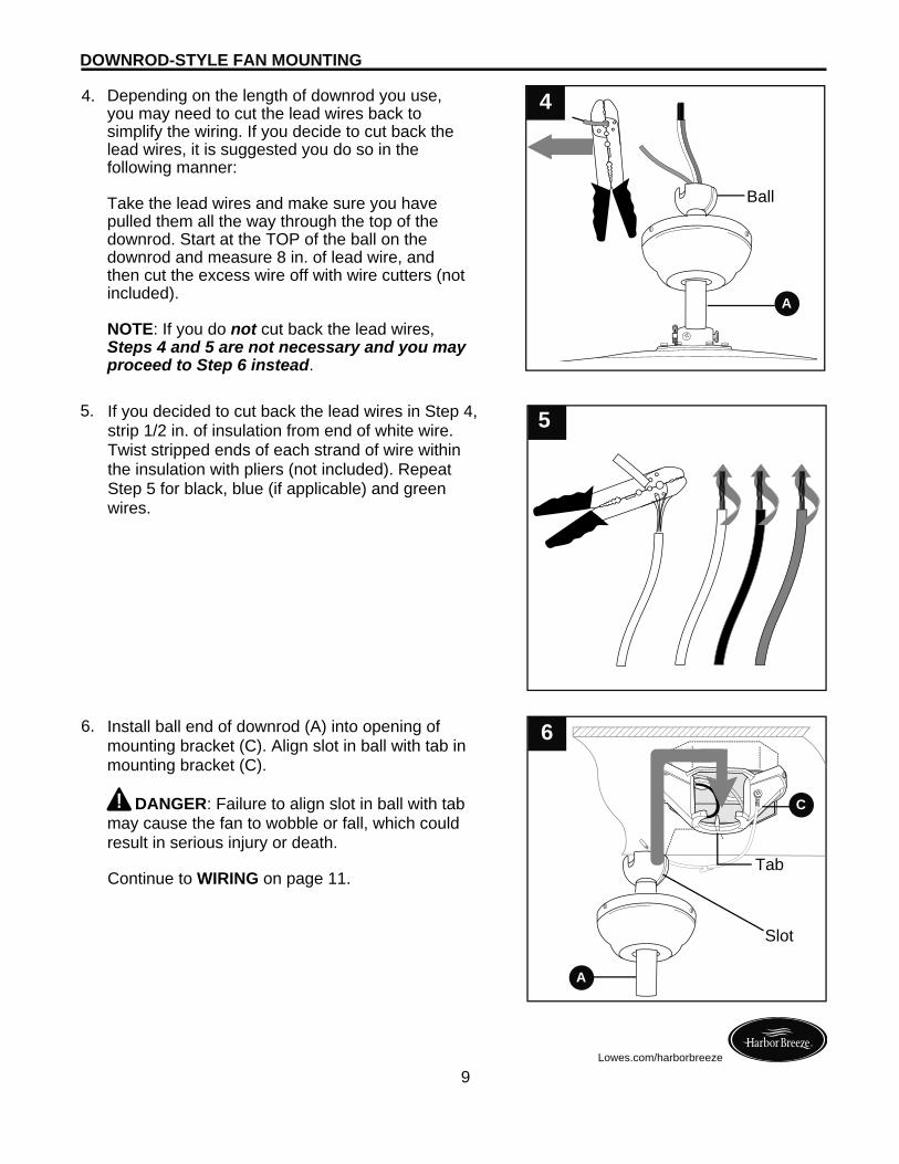
Depending on the length of downrod you use, you may need to cut the lead wires back to simplify the wiring. If you decide to cut back the lead wires, it is suggested you do so in the following manner:
Take the lead wires and make sure you have pulled them all the way through the top of the downrod. Start at the TOP of the ball on the downrod and measure 8 in. of lead wire, and then cut the excess wire off with wire cutters (not included).
NOTE: If you do not cut back the lead wires, Steps 4 and 5 are not necessary and you may proceed to Step 6 instead.
4.
Ball
5.
Install ball end of downrod (A) into opening of mounting bracket (C). Align slot in ball with tab in mounting bracket (C).
DANGER: Failure to align slot in ball with tab may cause the fan to wobble or fall, which could result in serious injury or death.
6.
Continue to WIRING on page 11.
A
C
A
DOWNROD-STYLE FAN MOUNTING
4
9
5
6
Lowes.com/harborbreeze
If you decided to cut back the lead wires in Step 4, strip 1/2 in. of insulation from end of white wire. Twist stripped ends of each strand of wire within the insulation with pliers (not included). Repeat Step 5 for black, blue (if applicable) and green wires.
Slot
Tab
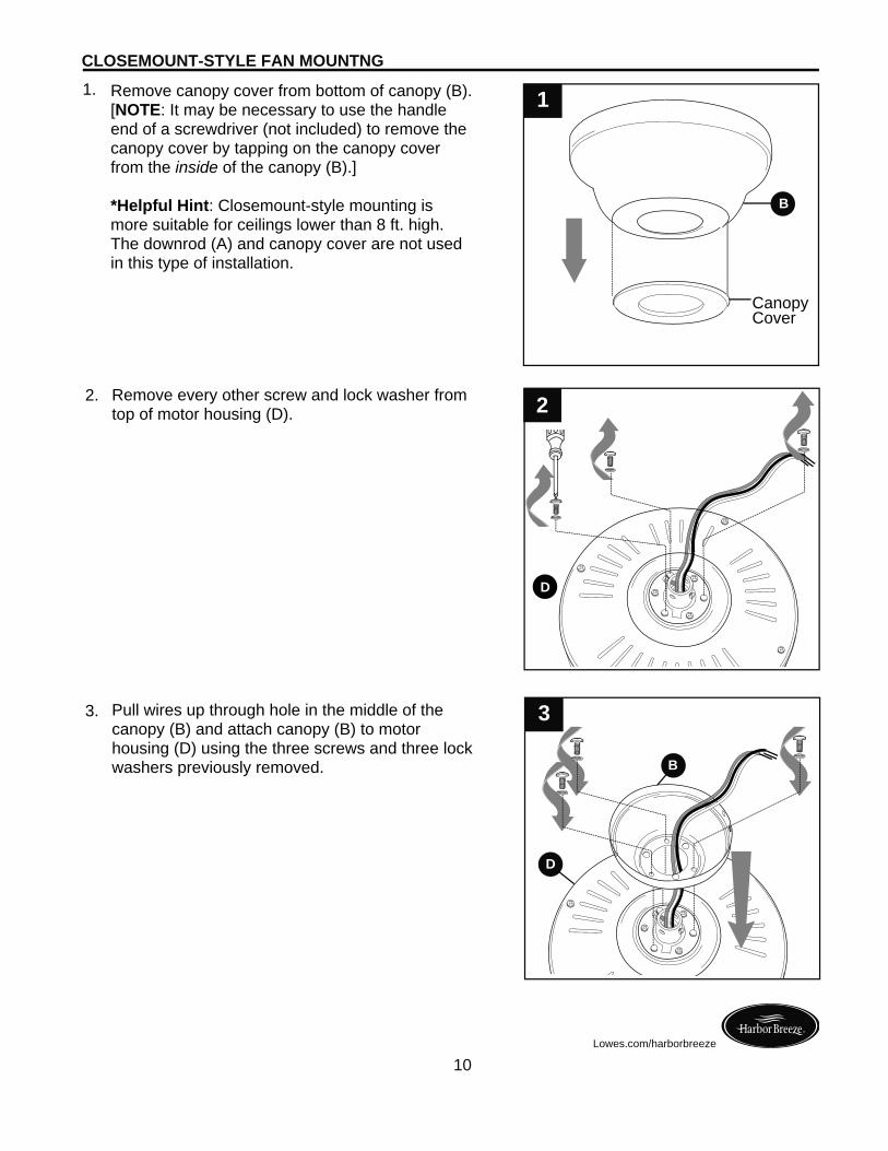
Remove canopy cover from bottom of canopy (B). [NOTE: It may be necessary to use the handle end of a screwdriver (not included) to remove the canopy cover by tapping on the canopy cover from the inside of the canopy (B).]
*Helpful Hint: Closemount-style mounting is more suitable for ceilings lower than 8 ft. high. The downrod (A) and canopy cover are not used in this type of installation.
1.
CanopyCover
Remove every other screw and lock washer from top of motor housing (D).
2.
3.
B
CLOSEMOUNT-STYLE FAN MOUNTNG
D
B
1
10
3
Lowes.com/harborbreeze
Pull wires up through hole in the middle of the canopy (B) and attach canopy (B) to motor housing (D) using the three screws and three lock washers previously removed.
2
D
B
D
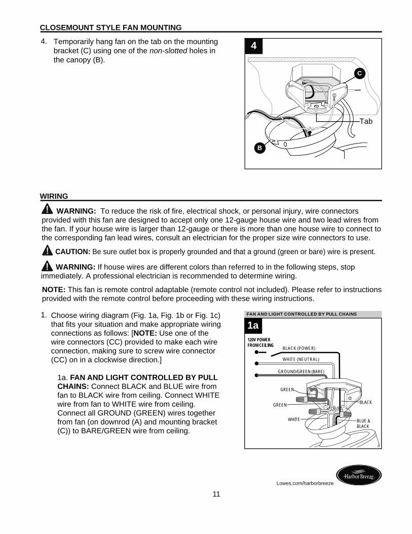
Temporarily hang fan on the tab on the mounting bracket (C) using one of the non-slotted holes in the canopy (B).
4.
WARNING: To reduce the risk of fire, electrical shock, or personal injury, wire connectors provided with this fan are designed to accept only one 12-gauge house wire and two lead wires from the fan. If your house wire is larger than 12-gauge or there is more than one house wire to connect to the corresponding fan lead wires, consult an electrician for the proper size wire connectors to use.
CAUTION: Be sure outlet box is properly grounded and that a ground (green or bare) wire is present.
WARNING: If house wires are different colors than referred to in the following steps, stop immediately. A professional electrician is recommended to determine wiring.
B
CLOSEMOUNT STYLE FAN MOUNTING
4
11Lowes.com/harborbreeze
WIRING
Choose wiring diagram (Fig. 1a, Fig. 1b or Fig. 1c) that fits your situation and make appropriate wiring connections as follows: [NOTE: Use one of the wire connectors (CC) provided to make each wire connection, making sure to screw wire connector (CC) on in a clockwise direction.]
1a. FAN AND LIGHT CONTROLLED BY PULL CHAINS: Connect BLACK and BLUE wire from fan to BLACK wire from ceiling. Connect WHITE wire from fan to WHITE wire from ceiling. Connect all GROUND (GREEN) wires together from fan (on downrod (A) and mounting bracket (C)) to BARE/GREEN wire from ceiling.
1.
Tab
C
NOTE: This fan is remote control adaptable (remote control not included). Please refer to instructions provided with the remote control before proceeding with these wiring instructions.
FAN AND LIGHT CONTROLLED BY TWO WALL SWITCHES
1aFAN AND LIGHT CONTROLLED BY PULL CHAINS
BLACK (POWER)
WHITE (NEUTRAL)
BLACK
GROUND/GREEN (BARE)
WHITE BLUE &BLACK
120V POWER FROM CEILING
GREEN
GREEN
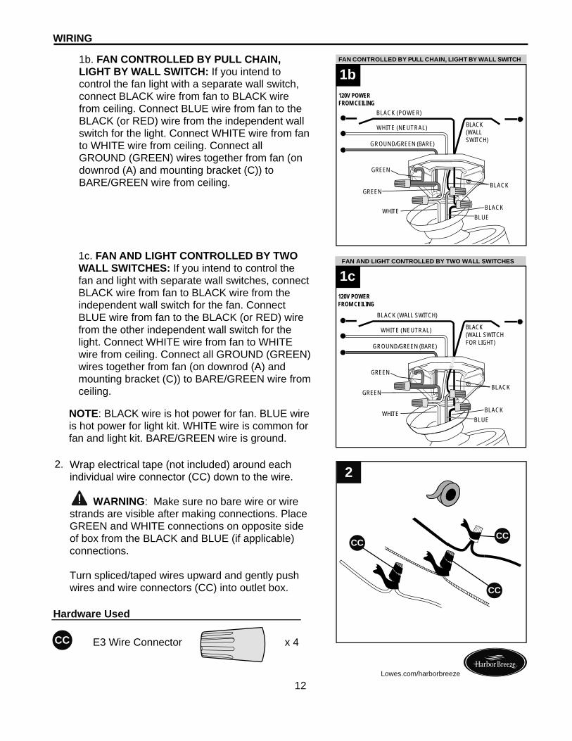
Wrap electrical tape (not included) around each individual wire connector (CC) down to the wire.
WARNING: Make sure no bare wire or wire strands are visible after making connections. Place GREEN and WHITE connections on opposite side of box from the BLACK and BLUE (if applicable) connections.
Turn spliced/taped wires upward and gently push wires and wire connectors (CC) into outlet box.
2.
12
WIRING
E3 Wire Connector x 4
Hardware Used
CC
CC
Lowes.com/harborbreeze
2
CC
CC
NOTE: BLACK wire is hot power for fan. BLUE wire is hot power for light kit. WHITE wire is common for fan and light kit. BARE/GREEN wire is ground.
1b. FAN CONTROLLED BY PULL CHAIN, LIGHT BY WALL SWITCH: If you intend to control the fan light with a separate wall switch, connect BLACK wire from fan to BLACK wire from ceiling. Connect BLUE wire from fan to the BLACK (or RED) wire from the independent wall switch for the light. Connect WHITE wire from fan to WHITE wire from ceiling. Connect all GROUND (GREEN) wires together from fan (on downrod (A) and mounting bracket (C)) to BARE/GREEN wire from ceiling.
1c. FAN AND LIGHT CONTROLLED BY TWO WALL SWITCHES: If you intend to control the fan and light with separate wall switches, connect BLACK wire from fan to BLACK wire from the independent wall switch for the fan. Connect BLUE wire from fan to the BLACK (or RED) wire from the other independent wall switch for the light. Connect WHITE wire from fan to WHITE wire from ceiling. Connect all GROUND (GREEN) wires together from fan (on downrod (A) and mounting bracket (C)) to BARE/GREEN wire from ceiling.
FAN AND LIGHT CONTROLLED BY TWO WALL SWITCHESFAN CONTROLLED BY PULL CHAIN, LIGHT BY WALL SWITCH
BLACK
BLACK(WALLSWITCH)
BLUE
1b
WHITE
BLACK (POWER)
WHITE (NEUTRAL)
GROUND/GREEN (BARE)
BLACK
FAN AND LIGHT CONTROLLED BY TWO WALL SWITCHESFAN AND LIGHT CONTROLLED BY TWO WALL SWITCHES
BLACK
BLACK(WALL SWITCHFOR LIGHT)
BLUE
1c
WHITE
BLACK (WALL SWITCH)
WHITE (NEUTRAL)
GROUND/GREEN (BARE)
BLACK
120V POWER FROM CEILING
120V POWER FROM CEILING
GREEN
GREEN
GREEN
GREEN
2.
WIRING
13Lowes.com/harborbreeze
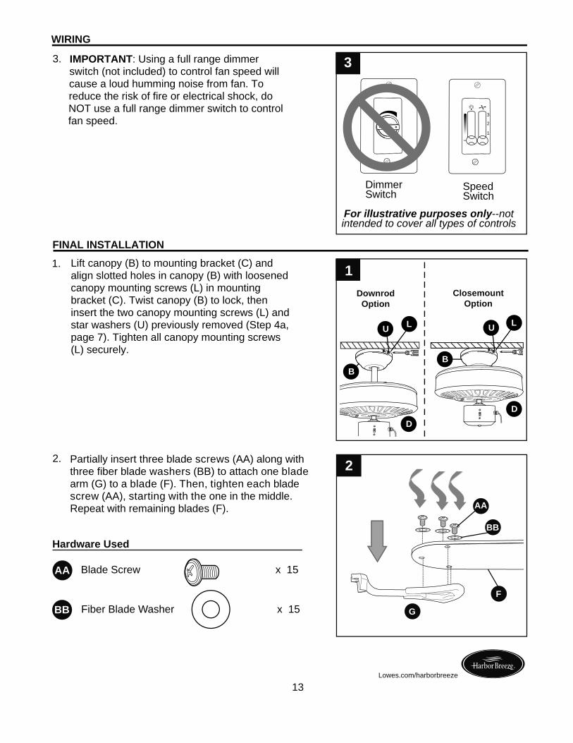
Partially insert three blade screws (AA) along with three fiber blade washers (BB) to attach one blade arm (G) to a blade (F). Then, tighten each blade screw (AA), starting with the one in the middle. Repeat with remaining blades (F).
Blade Screw x 15
Fiber Blade Washer x 15
2
AA
BB
F
G
Hardware Used
AA
BB
IMPORTANT: Using a full range dimmer switch (not included) to control fan speed will cause a loud humming noise from fan. To reduce the risk of fire or electrical shock, do NOT use a full range dimmer switch to control fan speed.
3.
1.
FINAL INSTALLATION
1
Dimmer Switch
Speed Switch
For illustrative purposes only--not intended to cover all types of controls
3
1
2
3
B
D
L
D
B
DownrodOption
ClosemountOption
Lift canopy (B) to mounting bracket (C) and align slotted holes in canopy (B) with loosened canopy mounting screws (L) in mounting bracket (C). Twist canopy (B) to lock, then insert the two canopy mounting screws (L) and star washers (U) previously removed (Step 4a, page 7). Tighten all canopy mounting screws (L) securely.
U LU
FINAL INSTALLATION
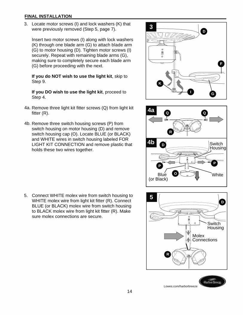
Connect WHITE molex wire from switch housing to WHITE molex wire from light kit fitter (R). Connect BLUE (or BLACK) molex wire from switch housing to BLACK molex wire from light kit fitter (R). Make sure molex connections are secure.
5.
14Lowes.com/harborbreeze
Locate motor screws (I) and lock washers (K) that were previously removed (Step 5, page 7).
Insert two motor screws (I) along with lock washers (K) through one blade arm (G) to attach blade arm (G) to motor housing (D). Tighten motor screws (I) securely. Repeat with remaining blade arms (G), making sure to completely secure each blade arm (G) before proceeding with the next.
If you do NOT wish to use the light kit, skip to Step 9.
If you DO wish to use the light kit, proceed to Step 4.
3.
4a. Remove three light kit fitter screws (Q) from light kit fitter (R).
Remove three switch housing screws (P) from switch housing on motor housing (D) and remove switch housing cap (O). Locate BLUE (or BLACK) and WHITE wires in switch housing labeled FOR LIGHT KIT CONNECTION and remove plastic that holds these two wires together.
4b.
4a
R
Q Q
F
GI
K
3
4b
D
R
5
MolexConnections
D
SwitchHousing
WhiteBlue (or Black)
O
P
SwitchHousing
P
D
15Lowes.com/harborbreeze
FINAL INSTALLATION
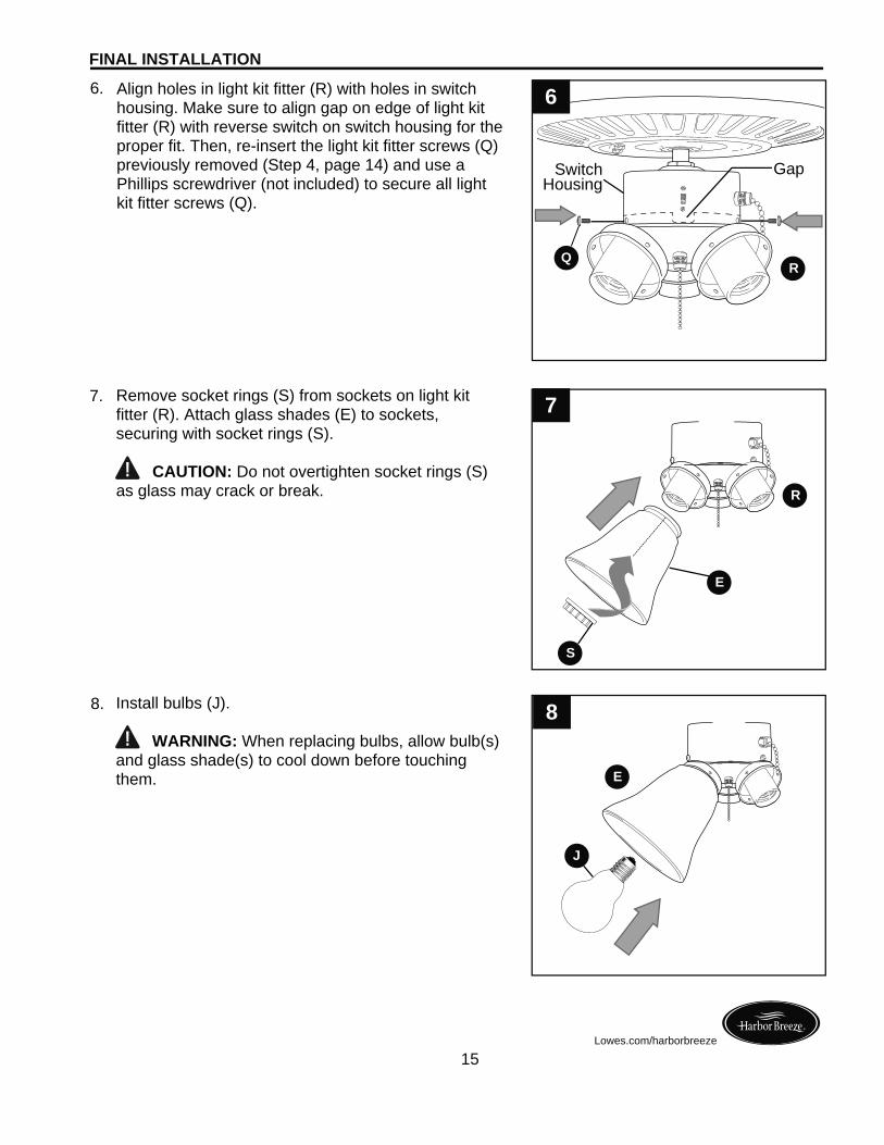
8. Install bulbs (J). WARNING: When replacing bulbs, allow bulb(s) and glass shade(s) to cool down before touching them.
8
Align holes in light kit fitter (R) with holes in switch housing. Make sure to align gap on edge of light kit fitter (R) with reverse switch on switch housing for the proper fit. Then, re-insert the light kit fitter screws (Q) previously removed (Step 4, page 14) and use a Phillips screwdriver (not included) to secure all light kit fitter screws (Q).
6.
Remove socket rings (S) from sockets on light kit fitter (R). Attach glass shades (E) to sockets, securing with socket rings (S).
CAUTION: Do not overtighten socket rings (S) as glass may crack or break.
7. 7
R
E
E
S
J
SwitchHousing
Gap
6
QR
FINAL INSTALLATION
16Lowes.com/harborbreeze
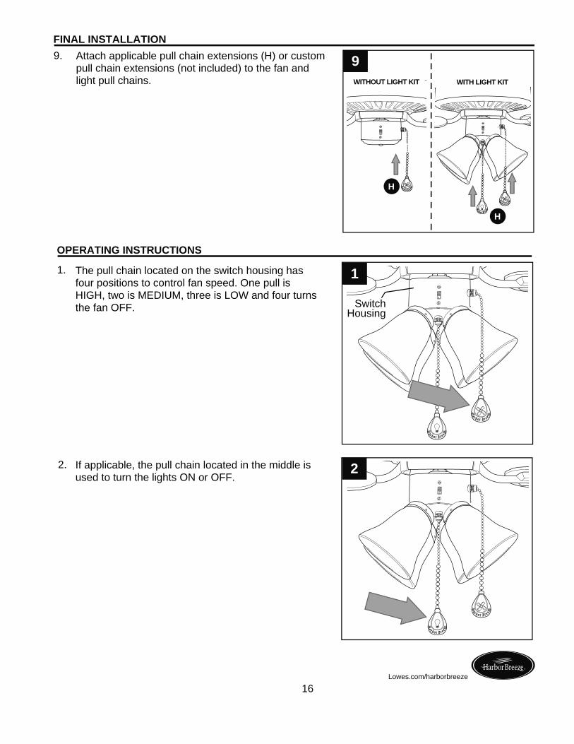
Attach applicable pull chain extensions (H) or custom pull chain extensions (not included) to the fan and light pull chains.
9.
OPERATING INSTRUCTIONS
2. If applicable, the pull chain located in the middle is used to turn the lights ON or OFF.
The pull chain located on the switch housing has four positions to control fan speed. One pull is HIGH, two is MEDIUM, three is LOW and four turns the fan OFF.
1.
SwitchHousing
H
H
9
1
2
WITHOUT LIGHT KIT WITH LIGHT KIT
17Lowes.com/harborbreeze
OPERATING INSTRUCTIONS
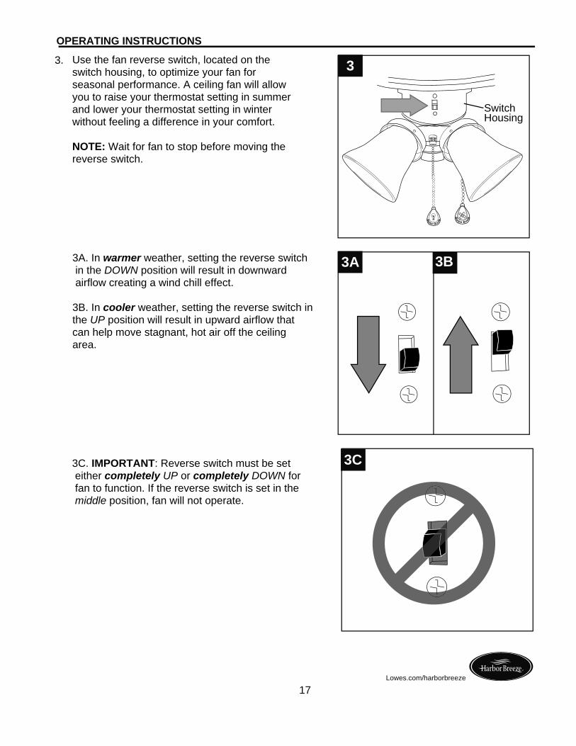
3C. IMPORTANT: Reverse switch must be set either completely UP or completely DOWN for fan to function. If the reverse switch is set in the middle position, fan will not operate.
3C
3. Use the fan reverse switch, located on the switch housing, to optimize your fan for seasonal performance. A ceiling fan will allow you to raise your thermostat setting in summer and lower your thermostat setting in winter without feeling a difference in your comfort.
NOTE: Wait for fan to stop before moving the reverse switch.
3
SwitchHousing
3A. In warmer weather, setting the reverse switch in the DOWN position will result in downward airflow creating a wind chill effect.
3B. In cooler weather, setting the reverse switch in the UP position will result in upward airflow that can help move stagnant, hot air off the ceiling area.
3A 3B
18Lowes.com/harborbreeze
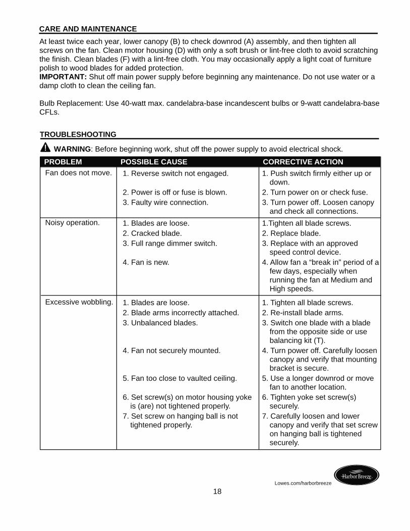
At least twice each year, lower canopy (B) to check downrod (A) assembly, and then tighten all screws on the fan. Clean motor housing (D) with only a soft brush or lint-free cloth to avoid scratching the finish. Clean blades (F) with a lint-free cloth. You may occasionally apply a light coat of furniture polish to wood blades for added protection.IMPORTANT: Shut off main power supply before beginning any maintenance. Do not use water or a damp cloth to clean the ceiling fan.
Bulb Replacement: Use 40-watt max. candelabra-base incandescent bulbs or 9-watt candelabra-base CFLs.
WARNING: Before beginning work, shut off the power supply to avoid electrical shock.
PROBLEM POSSIBLE CAUSE CORRECTIVE ACTIONFan does not move. 1. Reverse switch not engaged.
2. Power is off or fuse is blown.3. Faulty wire connection.
1. Push switch firmly either up or down.
2. Turn power on or check fuse.3. Turn power off. Loosen canopy
and check all connections.Noisy operation. 1. Blades are loose.
2. Cracked blade.3. Full range dimmer switch.
4. Fan is new.
1.Tighten all blade screws.2. Replace blade.3. Replace with an approved
speed control device.4. Allow fan a “break in” period of a
few days, especially when running the fan at Medium and High speeds.
Excessive wobbling. 1. Blades are loose.2. Blade arms incorrectly attached.3. Unbalanced blades.
4. Fan not securely mounted.
5. Fan too close to vaulted ceiling.
6. Set screw(s) on motor housing yoke is (are) not tightened properly.
7. Set screw on hanging ball is not tightened properly.
1. Tighten all blade screws.2. Re-install blade arms.3. Switch one blade with a blade
from the opposite side or use balancing kit (T).
4. Turn power off. Carefully loosen canopy and verify that mounting bracket is secure.
5. Use a longer downrod or move fan to another location.
6. Tighten yoke set screw(s) securely.
7. Carefully loosen and lower canopy and verify that set screw on hanging ball is tightened securely.
CARE AND MAINTENANCE
TROUBLESHOOTING
19Lowes.com/harborbreeze
The distributor warrants this fan to be free from defects in workmanship and materials present at time of shipment from the factory for Lifetime limited from the date of purchase. This warranty applies only to the original purchaser. The distributor agrees to correct any defect at no charge or, at our option, replace the ceiling fan with a comparable or superior model.
To obtain warranty service, present a copy of your sales receipt as proof of purchase. All cost of removal and reinstallation are the express responsibility of the purchaser. Any damage to the ceiling fan by accident, misuse or improper installation, or by using parts not produced by the manufacturer of this fan or affixing accessories not produced by the manufacturer of this fan, are the purchaser's own responsibility. The distributor assumes no responsibility whatsoever for fan installation during the limited lifetime warranty. Any service performed by an unauthorized person will render the warranty invalid.
Due to varying climatic conditions, this warranty does not cover changes in brass finish, rusting, pitting, tarnishing, corroding or peeling. Brass finish fans maintain their beauty when protected from varying weather conditions. Any glass provided with this fan is not covered by the warranty.
Any replacement of defective parts for the ceiling fan must be reported within the first year from the date of purchase. For the balance of the warranty, call our customer service department (at 1-800-643-0067) for return authorization and shipping instructions so that we may repair or replace the ceiling fan. Any fan or parts returned improperly packaged is/are the sole responsibility of the purchaser. There is no further express warranty. The distributor disclaims any and all implied warranties. The duration of any implied warranty which cannot be disclaimed is limited to the limited lifetime period as specified in our warranty. The distributor shall not be liable for incidental, consequential or special damages arising at or in connection with product use or performance except as may otherwise be accorded by law. This warranty gives you specific legal rights and you may also have other rights which vary from state to state. This warranty supersedes all prior warranties.
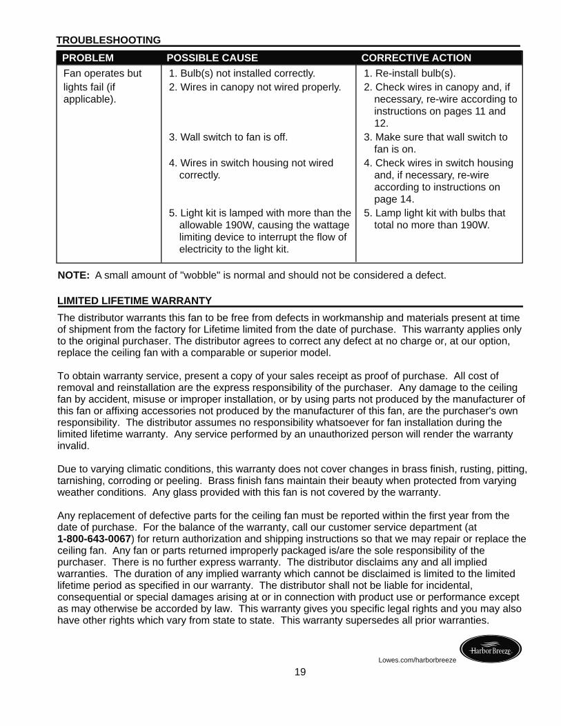
NOTE: A small amount of "wobble" is normal and should not be considered a defect.
LIMITED LIFETIME WARRANTY
TROUBLESHOOTING PROBLEM POSSIBLE CAUSE CORRECTIVE ACTION
Fan operates butlights fail (if applicable).
1. Bulb(s) not installed correctly.2. Wires in canopy not wired properly.
3. Wall switch to fan is off.
4. Wires in switch housing not wired correctly.
5. Light kit is lamped with more than the allowable 190W, causing the wattage limiting device to interrupt the flow of electricity to the light kit.
1. Re-install bulb(s).2. Check wires in canopy and, if
necessary, re-wire according to instructions on pages 11 and 12.
3. Make sure that wall switch to fan is on.
4. Check wires in switch housing and, if necessary, re-wire according to instructions on page 14.
5. Lamp light kit with bulbs that total no more than 190W.
Printed in China
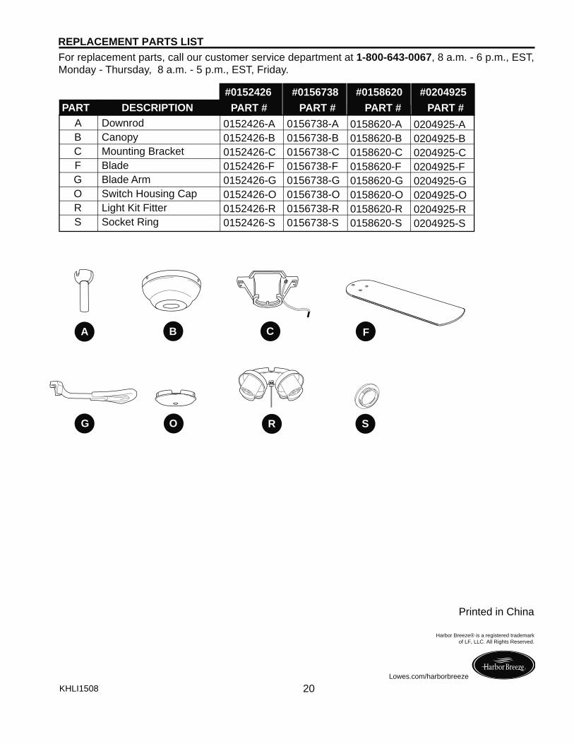
REPLACEMENT PARTS LISTFor replacement parts, call our customer service department at 1-800-643-0067, 8 a.m. - 6 p.m., EST, Monday - Thursday, 8 a.m. - 5 p.m., EST, Friday.
KHLI1508
Harbor Breeze® is a registered trademark of LF, LLC. All Rights Reserved.
20Lowes.com/harborbreeze
F
G O
B CA
SR
PART DESCRIPTION#0152426 #0156738 #0158620 #0204925 PART # PART # PART # PART #
A Downrod B Canopy C Mounting Bracket F Blade G Blade Arm O Switch Housing Cap R Light Kit Fitter S Socket Ring
0152426-A0152426-B0152426-C0152426-F0152426-G0152426-O0152426-R0152426-S
0156738-A0156738-B0156738-C0156738-F0156738-G0156738-O0156738-R0156738-S
0158620-A0158620-B0158620-C0158620-F0158620-G0158620-O0158620-R0158620-S
0204925-A0204925-B0204925-C0204925-F0204925-G0204925-O0204925-R0204925-S