Embed Size (px)
Citation preview

U N I N T E R R U P T I B L E P O W E R S U P P LY ( U P S ) + L I G H T I N G F L O W D I M M E R S TA B I L I Z E R S + P O W E R S U P P LY + S TAT I C I N V E R T E R S + P H O T O V O LTA I C I N V E R T E R S + M I C R O T U R B I N E S + V O LTA G E S TA B I L I S E R S
USER’S MANUAL
UNINTERRUPTIBLE POWER SOURCE
SPS ADVANCE Series


3
GENERAL INDEX
SALICRU
General index
1. Introduction
1.1. Gratefulness letter
1.2. Using this manual1.2.1. Used conventions and symbols1.2.2. For more information and/or help1.2.3. Safety and first aid
2. Quality and standard guarantee
2.1. Management declaration
2.2. Standard
2.3. Environment.
3. Description
4. Presentation of system
4.1. Front Panel
4.2. Introducing the LCD display
4.3. Audible alarm introduction
4.4. Back panel4.4.1. 750 / 1000 VA models4.4.2. 1500 / 2000 VA models4.4.3. 3000 VA model
5. Installation
5.1. Inspecting the Equipment
5.2. Placement
5.3. Charging 5.3.1. Load connection
5.4. Modem / Phoneline Connection
5.5. DC Start function
5.6. Turn On/Off
5.7. UPS Setup5.7.1. Tower Setup 5.7.2. Rack-Mount Setup
5.8. Emergency Power Off (E.P.O.) set up
5.9. Additional battery installation setup 5.9.1. 1500 / 2000 VA models 5.9.2. 3000 VA model
5.10. Communication Ports5.10.1. RS232 + Optocouplers5.10.2. USB port: HID protocol5.10.3. AS400 interface (Optional). Not available for models lower
than 1500 VA
5.11. Software installation
6. Maintenance, warranty and service
6.1. Troubleshooting guide6.1.1. Audible Alarm Trouble Shooting6.1.2. General Trouble Shooting
6.2. Battery replacement6.2.1. 750 / 1000 VA models6.2.2. 1500 / 2000 VA models6.2.3. 3000 VA model
6.3. Warranty conditions6.3.1. Covered product6.3.2. Warranty terms6.3.3. Out of the scope of supply
6.4. Available maintenance and service contracts
6.5. Technical service network
7. Annexes
7.1. Specification

4
INTRODUCTION
SALICRU
1. Introduction
1.1. Gratefulness letter
We would like to thank you in advance for the trust you have placed in us by purchasing this product. Read this instruc-tion manual carefully before starting up the equipment and keep it for any possible future consult that can arise.
We remain at you entire disposal for any further information or any query you should wish to make.
Yours sincerely.
� The equipment here described can cause impor-tant physical damages due to wrong handling. This is why, the installation, maintenance and/or fixing of the here described equipment must be done by our staff or specifically authorised.
� According to our policy of constant evolution, we re-serve the right to modify the specifications in part or in whole without forewarning.
� All reproduction or third party concession of this manual is prohibited without the previous written authorization of our firm.
1.2. Using this manual
The target of this manual is to give explanations and pro-cedures for the installation and operating of the equipment. This manual has to be read carefully before installing and operating it. Keep this manual for future consults.
This equipment has to be installed by qualified staff and, the simple help of this manual, it can usable by personnel without specific training.
1.2.1. Used conventions and symbols
«Warning» symbol. Carefully read the indicated paragraph and take the stated prevention meas-
ures.
«Danger of electrical discharge» symbol. Pay special attention to it, both in the indication on the
equipment and in the paragraph referred to this user’s manual.
i «Main protective earthing terminal» symbol. Con-nect the earth cable coming from the installation to
this terminal.
«Earth bonding terminal» symbol. Connect the earth cable from the loads or battery cabinet to this terminal.
i «Notes of information» symbol. Additional topics that complement the basic procedures.
Preservation of the environment: The presence of this symbol in the product or in their associated doc-umentation states that, when its useful life is expired,
it will not be disposed together with the domestic residuals. In order to avoid possible damages to the environment, separate this product from other residuals and recycle it suitably. The users can contact with their provider or with the pertinent local authorities to be informed on how and where they can take the product to be recycled and/or dis-posed correctly.
1.2.2. For more information and/or helpFor more information and/or help of the version of your spe-cific unit, request it to our Service and Technical Support (S.T.S.).
1.2.3. Safety and first aidTogether with the equipment and this «User and installa-tion manual», it is provided the information regarding to «Safety instructions» (See document EK266*08). Before proceeding to the installation or commissioning, check that both information are available; otherwise request them. It is obligatory the compliance of the «Safety instructions», being the user the legal responsible regarding to its obser-vance. Once read, keep them for future consults that can arise.
USER'S MANUAL

5
QUALITY AND STANDARD GUARANTEE
SALICRU
2. Quality and standard guarantee
2.1. Management declaration
Our target is the client’s satisfaction, therefore this Manage-ment has decided to establish a Quality and Environmental policy, by means of installation a Quality and Environmental Management System that becomes us capable to comply the requirements demanded by the standard ISO 9001 and ISO 14001 and by our Clients and concerned parts too.
Likewise, the enterprise Management is committed with the development and improvement of the Quality and Environ-mental Management System, through:
• The communication to all the company about the im-portance of satisfaction both in the client’s requirements and in the legal and regulations
• The Quality and Environmental Policy diffusion and the fixation of the Quality and Environment targets.
• To carry out revisions by the Management. • To provide the needed resources.
2.2. Standard
The SPS ADVANCE product is designed, manufactured and commercialized in accordance with the standard EN ISO 9001 of Quality Assurance. The marking shows the conformity to the EEC Directive (quoted between brackets) by means of the application of the following standards:
• 2006/95/EC of Safety of Low Voltage• 2004/108/EC of Electromagnetic Compatibility (EMC).• in accordance with the specifications of the harmonized
standards. Standards of reference: • EN 60950-1: Equipment Information Technology. Secu-
rity. Part 1: General requirements.• IEC/EN 62040-2: Uninterruptible power supplies
(UPS). Part 2: Requirements for Electromagnetic Compatibility (EMC).
• IEC/EN 62040-3: Uninterruptible power supplies (UPS). Part 3: Methods of operation and specification of test requirements.
The declaration of conformity CE of the product is at the disposal of the client previous express request to our head offices.
2.3. Environment.
Equipment recycling at the end of its useful life:Our company commits to use the services of authorised societies and according to the regulations, in order to treat the recovered product at the end of its useful life (contact your distributor).
Packing:To recycle the packing, follow the legal regulations in force.
Batteries:The batteries mean a serious danger for health and envi-ronment. The disposal of them must be done in accordance with the standards in force.

6
DESCRIPTION
3. Description
This series is a compact and fully pure sinewave line inter-active UPS, and it designs for application and environment, such as desktops, servers, workstations, and other net-working equipments. This model is available in the output ratings of 750, 1000, 1500, 2000, and 3000VA. This se-ries protects your sensitive electronic equipments against power problems including power sags, spike, brownouts, line noise, and blackouts.
This series designs from two-in-one form factor; it can be placed either in Rack 2U or Tower. The front panel of the UPS includes LED indicators and four push buttons (Power Switch, UPS Test/Silence, Configure, and Enter) that allow to monitor easily, configuration and control, AC line-in, noti-fication of site wiring fault and output load status of the UPS. It also includes four LCD bar graphic (Load/Battery Level Indication); two status indications (On AC, On Battery); five alarm indications (Overload, Over Temperature, Site Wiring Fault, Battery Fault, Self Test Failure). A push button from the front panel allows silencing of the AC fail alarm and the initiation of the UPS self test sequence as well. The UPS case for 750 ~ 2000VA is made of plastic as well as 3000VA is made of metal.
This series is powered from the AC mains and supply AC outputs via receptacles on the rear panel. Communication and control to the unit is available through serial or USB ports located on the rear panel. The serial port will sup-port communications directly with a server. The communi-cations protocol for the serial ports shall conform to true RS232 interface..
• Features:
� Microprocessor control guarantees high reliability. � High frequency design. � Built-in boost and buck AVR. � User replaceable design for 1500VA or above. � Selectable output range and line sensitive. � Cold startup capability. � Optocouplers/RS-232/USB communication port. � SNMP allows for web-based remote or monitoring
management. � Enable to extend runtime with scalable external bat-
tery pack for 1500VA or above. � Overload, Short-circuit, and overheat protection. � Rack/Tower 2 in 1 Design. � 19” rack mount available for all models.
USER'S MANUAL

7
PRESENTATION OF SYSTEM
SALICRU
4. Presentation of system
4.1. Front Panel
The total view of the LCD (in front panel):
Fig. 1. The total view of the LCD
The primary introduction to above figure:
1. Power Switch ON/OFF.
� To turn on the UPS, press the “ON/OFF” button more than three seconds.
� To turn off the UPS, press and hold this button until you hear the UPS beep ceases..
2. UPS Test/ Alarm Silence Switch.
� When AC utility power is available and battery is full charged, it is possible to perform self-test function by pressing and holding the “TEST” button for five seconds.
� To disable alarm buzzer, press this button for a second that will turn off the alarm buzzer. Each time a new alarm event is encountered the alarm that will sound and press this button to turn off the alarm.
Note: Unable to disable alarm buzzer as below con-ditions: Low Battery, Overload, Fan Failed, Fan Fault Time Out, Over Temperature.
3. Configure switch: To reconfigure the internal UPS setup options, follow the procedure as below:
� Step 1: By entering the “CNFG” button more than three seconds, UPS will transfer to “Rated voltage” configure mode.
� Step 2: Pressing the “CNFG” button more than one second, the UPS allows you to select the “Rated voltage one by one.
� Step 3: After selecting the mode, press the “ENTER” button more than three seconds, the “Rated voltage” is configured.
� Step 4: UPS will automatically transfer to “Input type” configure mode.
� Step 5: Pressing the “CNFG” button more than one second, the UPS will allow you to select the “Input type” one by one.
� Step 6: After selecting the mode, press the “ENTER” button more than three seconds, the “Input type” is configured..
4. Enter switch: Press the «ENTER» button after you choose the mode.
5. Input parameters (voltage & frequency): This part gives the information of the AC utility power, including input voltage and input frequency (autosensing).
Fig. 2. The figure indicates that the input voltage is 230V and the input frequency is 50Hz.
6. Auto Voltage Regulation: The LCD symbol indicates that the UPS is in AVR (Auto
Voltage Regulation) mode.
7. Line Mode: The LCD symbol illuminates when UPS is on and the AC source is available.
8. Battery.
� The LCD symbol indicates that the battery is in charging mode.

8
PRESENTATION OF SYSTEM
� The LCD symbol indicates that the bat-tery is working (the AC source is not available),and it will flicker every second when battery is low.
� The battery symbol also could show battery level: There are four segments to indicate the amount of battery capacity remaining. The higher the battery capacity, the more indicators that will be illuminated. Each indicator designates a 25% capacity level. Please see the following capacity level respectively. This is: – 100% to 76% , all of the four indicators
illuminate. – 75% to 51% , three indicators illuminate. – 50% to 26% , two indicators illuminate. – 25% to 11% , only one indicator illumi-
nates. – 10% to 0% , none of the indicator illumi-
nates.
When the battery is empty, the symbol will flicker every second.
9. Output parameters (voltage & frequency): This part gives the information of the output, including output voltage and output frequency.
Fig. 3. The figure indicates that the output voltage is 230V and the output frequency is 50Hz.
10. Capacity of Load %: The LCD gives the load informa-tion by displaying the load percentage.
Fig. 4. The figure indicates the capacity of Load.
Normally, the symbol will not illuminate, but when the load percentage is more than 110% (overload),it will flicker every second. If over load is time out , it will illuminate constantly.
11. Site Fault: The Site Fault indicator will light when UPS is plugged into an improperly utility. This function is only available for 120Vac models
12. Fault code: When UPS fails, the corresponding LCD symbol will illuminate to show the type of failure.
� Battery bad: When the battery of the UPS is bad, the symbol will be displayed constantly.
� Over load time out: When UPS is Over load time out, the symbol will be dis-played constantly. At the same time, the symbol will
be displayed constantly, and the output voltage is 0Vac 0Hz.
� Battery missing: If the battery connection is not good, the LCD will display “FAULT CODE 1”.
� Fan fail: If the fan is locked, The symbol “FAULT CODE 2” will flicker every second; if the time is out. The symbol will be displayed constantly.
� Over temperature: If the temperature of the UPS is too high, The LCD will display “FAULT CODE 3” constantly.
� Output invalid: If output voltage is out of range, the LCD will display “FAULT CODE 4” constantly.
� Battery overcharged: The LCD will display “FAULT CODE 5” constantly.
� Output short circuit: The LCD will display “FAULT CODE 6” constantly.
� Other fault type: The LCD will display “FAULT CODE 8” constantly.
13. Input type (Operation mode).
Fig. 5. Operation mode indication
� Normal: The UPS accepts a input voltage range of ±20%.
� Generator: The low frequence transfer point changes at 40Hz and there is not limit for the high frequence transfer point.
� Extended margin: The UPS accepts a input voltage margin of -30% to +20%.
14. Output voltage margin: The UPS output voltage se-lection: 110Vac / 120Vac / 127Vac o 220Vac / 230Vac / 240Vac.
Fig. 6. Output voltage margin indication
110Vac/120Vac/127Vac are LV mode (low voltage).
220Vac/230Vac/240Vac are HV mode (high voltage).
Example: To a HV UPS, after selection the 230Vac mode (default selection) by the switches “CNFG” and “ENTER”, the output voltage will be approximately 230V, and the LCD display will be how the next figure shows:
Fig. 7. Indication after the selection of HV 230 Vac mode.
USER'S MANUAL

9
PRESENTATION OF SYSTEM
SALICRU
Examples to the LCD display:
a. If the mains supply exist:
b. If the mains supply do not exist:
4.2. Introducing the LCD display
ICON STATUS DESCRIPTION
Steady The UPS is operating on mains power
Steady UPS is in AVR mode (AVR - Auto Voltage Regulation)
Steady Battery is in charging mode
Steady Battery is in discharging mode
Battery capacity: 76% ~ 100%
Battery capacity: 51% ~ 75%
Battery capacity: 26% ~ 50%
Battery capacity: 11% ~ 25%
Battery capacity: 0% ~ 10%
Flashing UPS is overload
Steady UPS is overload and the time is out
Steady UPS is overload and the time is out
SteadyUPS is plugged intro an improperly polarity (only for LV models)
Steady Battery bad
Code 1 Battery disconnect
Code 2 Fan fail
Code 3 Over temperature
Code 4 Output voltage is out of range
Code 5 Battery overcharged
Code 6 Output short circuit
Code 8 Other fault type
Table 1. Display LCD symbols
4.3. Audible alarm introduction
Condition Alarm
Backup mode (Power Failure) Sounding every four seconds
Low Battery Sounding every second
UPS fault Continuously Sounding
Overload Sounding every second
Battery Replacement Sounding every second
Table 2. Alarm warning frequency

10
PRESENTATION OF SYSTEM
4.4. Back panel
4.4.1. 750 / 1000 VA models
Fig. 8. View of the 750 and 1000 VA models
No.Function
LV model(110/120/127Vac) HV model(220/230/240Vac)
1 Modem / Network Surge Protection
2 RS232 / Dry-Contact Communication Port
3 USB Communication Port
4 AC Input Power cord AC Input & Protection
5 AC Output NEMA AC Output IEC
Table 3. Rear panel description for LV and HV models table
4.4.2. 1500 / 2000 VA models
4.4.2.1. UPS module
Fig. 9. Rear panel for HV model
1000-LV 750-LV 1000-HV 750-HV
Fig. 10. Rear panel for LV model
USER'S MANUAL

11
PRESENTATION OF SYSTEM
SALICRU
No.Function
LV model (110/120/127Vac) HV model (220/230/240Vac)
1 RS232 / Dry-Contact Communication Port
2 SNMP Port or AS400
3 USB Port
4 EPO
5 Modem / Network Surge Protection
6 N/A Input Breaker
7 AC Output
8 AC Input
9 External Battery Connector
Table 4. Rear panel description for LV and HV models table
4.4.2.2. Battery module
Fig. 11. Rear panel for HV model Fig. 12. Rear panel for LV model
4.4.3. 3000 VA model
Fig. 13. Rear panel for HV model Fig. 14. Rear panel for LV model
No.Function
LV model (110/120/127Vac) HV model (220/230/240Vac)
1 Output thermic protection
2 AC Output
3 AC Input
4 Modem / Network Surge Protection
5 Input Breaker N/A
6 Input Power Cord N/A
7 SNMP Slot or AS400
8 External Battery Connector
9 EPO
10 USB Port
11 RS232 / Dry-Contact Communication Port
Table 5. Rear panel description for LV and HV models table

12
INSTALLATION
5. Installation
5.1. Inspecting the Equipment
Inspect the UPS upon receipt. If the UPS has been dam-aged during shipment, keep the box and packing material for the carrier. Notify the carrier and dealer immediately.
5.2. Placement
This UPS should be installed indoors with adequate airflow and free of contamination. Locate it in a clean and indoor environment, free from moisture, flammable liquids, and direct sunlight. Maintain a minimum clearance of 4 inches (100mm); an ambient temperature range must be 0°C to 40°C (32°F to 104°F), and operating humidity range must be 20% to 80% relative humidity (non-condensing)..
The long term uses at ambient temperature in higher than 25°C which should reduce battery life.
In addition, place the UPS unit away from the monitor at least 20cm. to avoid interference.
5.3. Charging
This UPS is shipped from the factory with its internal battery fully charged; however, some charge may be lost during shipping. The battery should be recharged prior to use. Plug the UPS into an appropriate power supply and allow the UPS to charge at least 4 hours.
5.3.1. Load connectionConnect one load-related device to each of the power re-ceptacles supplied at the rear of the UPS.
5.4. Modem / Phoneline Connection
Plug incoming telephone line into the “In” socket at the back of the UPS. Use on telephone line cable and plug one end of the telephone line cable to the “Out” socket at the back of the UPS. Plug the other end to the modem input socket.
5.5. DC Start function
DC Start Function enables UPS to be started up when AC utility power is not available and battery is full charged. Just simply press the On/Off switch to turn on the UPS.
5.6. Turn On/Off
To turn on/off the UPS, you should press the on/off switch three seconds at least.
5.7. UPS Setup
All models series are designed for tower and rack purpose. They can be installed as a 19 inch equipment rack, and 3000 VA can be placed in a tower (with optional stand) as well. Please follow the instruction for Tower Setup or Rack-Mount Setup.
5.7.1. Tower Setup This series can be placed in horizontally and vertically. 3000 VA model is designed in a rack itself. As a tower, it is provided with the optional UPS stand to stabilize the UPS when the UPS is positioned in vertically. The UPS stand must be attached to the bottom of the tower.
5.7.1.1. 750 / 1000 VA models
Fig. 15. Front view 1500 / 2000 VA models
USER'S MANUAL
13
INSTALLATION
SALICRU
5.7.1.2. 1500 / 2000 VA modelsUPS and Battery modules integrate into three types of tower forms:
Tower form 1 Tower form 2
Fig. 16. Integrated format views 1 and 2 UPS - Bat-teries
Tower form 3
Fig. 17. Integrated format view 3 UPS - Batteries
5.7.1.3. 3000 VA modelFollow the next steps for setup:
1. Slide down the UPS vertically and put two UPS stands at the end of the tower.
Fig. 18. View of the setup first step
2. Place the UPS into two stands carefully.
Fig. 19. UPS placed in his stands
5.7.2. Rack-Mount Setup750/1000/1500/2000 VA (optional) and 3000 VA can be in-stalled in 19” racks. And the UPS and external battery en-closure need 2U of valuable rack space. Use the following procedure to install UPS in a rack.
5.7.2.1. 750 / 1000 VA models (optional) 1. Align the mounting ears with screw holes on the side
of the UPS.
Fig. 20. Placement lateral stands
2. Install rack-mounting rails with the screws provided tightened up into rack enclosure.
Fig. 21. Install rack-mounting rails
14
INSTALLATION
3. Insert UPS into the slide assemblies and lock it in the rack enclosure.
Fig. 22. Attaching the UPS in the rack cabinet
4. Add up the front panels for both sides. The load can be connected.
Fig. 23. End of the installation
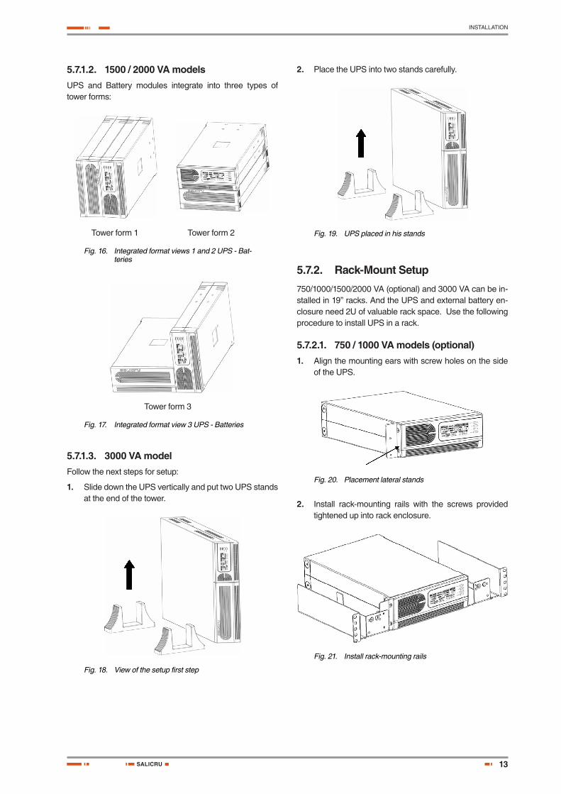
5.7.2.2. 1500 / 2000 VA models (optional) 1. UPS and Battery integrate into a rack form:
a. Place the UPS on a flat and in a clean place that the front side of the UPS is facing to you.
b. 2. Disconnect the cable from the UPS and Battery modules. .
Fig. 24. UPS and Battery are disconnected
c. Loosen the screws and remove the UPS and Bat-tery modules cover from the unit.
Fig. 25. Removal of screws and covers
d. Pull two covers toward the direction shown as below.
Fig. 26. Removing covers
e. Align the mounting bracket with the screw holes on the each side of UPS and Battery modules and secure with the supplied screws.
Fig. 27. Align the mounting bracket
f. Reinstall the UPS and Battery modules cover.
Fig. 28. Covers reinstallation
USER'S MANUAL

15
INSTALLATION
SALICRU
g. Tighten all screws up to front panels and setup rack-mount for front side is completed.
Fig. 29. End of the front side rack-mount
h. Align two small mounting brackets at the rear of UPS and Battery modules and secure with the supplied screws. Install Output receptacles at the rear panel of the UPS.
Fig. 30. Beginning rear mounting
i. Setup rack-mount is completed and to connect the UPS.
Fig. 31. End of the rack mounting
2. Battery and Battery modules integrate a rack form:
Fig. 32. Two battery modules in rack form
The rackmount kit for connecting the UPS-to-Bat-tery & Battery-to-Battery modules is different.
Please contact your dealer for further details.
5.7.2.3. 3000 VA model (optional)Install the 3000 VA series into 19” rack as shown below:
1. Turn on the UPS and connect the load.
2. After installing the UPS into rack, the load may be con-nected. Make sure the load equipment is turned off, then plug all loads into the output receptacle properly protected by a circuit breaker of fuse in accordance with national and local electrical codes.
Fig. 33. 3000 VA model in 19” rack
5.8. Emergency Power Off (E.P.O.) set up
1500/2000 VA and 3000 VA include E.P.O. port that allows power to be shut down the protected equipment immedi-ately and does not follow the shutdown procedure from any power management software.
Follow the procedure to install the E.P.O. switch as below:
1. Check the UPS is turned off.
2. Remove the E.P.O. connector from the E.P.O. port on the rear panel of UPS.
3. Connect isolated, normally-open, dry contacts (rated to handle 60 Vdc maximum, 30 Vac RMS maximum, and 20 mA maximum) across the EPO device to Pin 1 and Pin 2.
4. Reconnect the E.P.O. connector to the E.P.O. port.
5. Verify that the externally-connected E.P.O. switch is not activated to enable power to the UPS output re-ceptacles.
6. Plug in the UPS, then pressing power switch “ON/OFF” button to turn on the UPS.
7. Activate the external E.P.O. switch to test the E.P.O. function.
8. De-activate the external E.P.O. switch and restart the UPS.
16
INSTALLATION
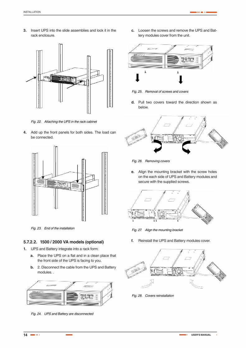
5.9. Additional battery installation setup
1500/2000 VA and 3000 VA include external battery port that allow to provide additional battery runtime. 1500/2000 VA model has no internal battery, and 3000 VA has de-signed an internal battery inside the UPS.
Connecting battery cable to external battery port may occur sparkle if adding up additional battery.
Follow the procedure to install additional battery as below:
5.9.1. 1500 / 2000 VA models There are two external battery ports for each side of UPS itself and battery pack.
1. Connect the battery cable to the external battery port of the rear of UPS.
2. Then connect the supplied battery cable from ex-tended battery module to the external battery port of the rear of previous UPS.
3. If continuing to add up extended battery pack, repeat above steps.
5.9.1.1. Additional battery connection in rack form
Fig. 34. Rear view of the additional battery connection
5.9.1.2. Additional battery connection in tower form
Fig. 35. Rear view of the additional battery connection
5.9.2. 3000 VA modelThere is one external battery port for the UPS itself.
1. Connect the supplied battery module cable from ex-tended battery module to the external battery port of the rear of UPS.
2. If continuing to add up extended battery module, re-peat above steps.
5.10. Communication Ports
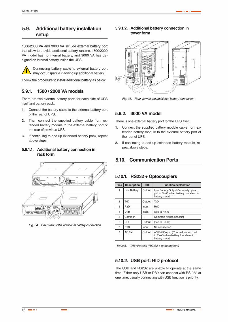
5.10.1. RS232 + Optocouplers
Pin# Description I/O Function explanation
1 Low Battery Output Low Battery Output (*normally open, pull to Pin#5 when battery low alarm in battery mode)
2 TxD Output TxD
3 RxD Input RxD
4 DTR Input (tied to Pin#6)
5 Common -- Common (tied to chassis)
6 DSR Output (tied to Pin#4)
7 RTS Input No connection
8 AC Fail Output AC Fail Output (**normally open, pull to Pin#5 when battery low alarm in battery mode)
Table 6. DB9 Female (RS232 + optocouplers)
5.10.2. USB port: HID protocolThe USB and RS232 are unable to operate at the same time. Either only USB or DB9 can connect with RS-232 at one time, usually connecting with USB function is priority.
USER'S MANUAL

17
INSTALLATION
SALICRU
5.10.3. AS400 interface (Optional). Not available for models lower than 1500 VA
This UPS has the AS400 communications as an op-tion, through a female DB9 connector, which allows to communicate with other equipments like the standard RS232+optocouplers simultaneously, but, the AS400 pro-vides dry contacts from relays instead of optocouplers and it has a higher quantity of alarms.
Its installation is very easy and not complicated:
1. Loosen and remove the screws from cover 2, for models up to 2000 VA or 7 for higher models. This cover is located in the rear side of the equipment.
2. Remove the cover and keep it in safe place.
3. Insert the AS400 card into the guides that are visible and enter it until is set with the connector of the bottom.
4. Put back the screws that fix the cover integrated with the AS400 card.
The following table and diagram, shows the pin-out of fe-male DB9 connector and its function.
Do not apply values higher than 24 V DC and 1 A to the pins of the AS400 connector..
Pin# Description E/S
1 UPS failure Output
2 General alarm Output
7 Low Battery Output
8 UPS On Output
9 Mains failure Output
5 Common Input
1
5
6
9
Table 7. DB9 Connector Pin-out and his function
5.11. Software installation
WinPower is a brand new UPS monitoring software, which provides user-friendly interface to monitor and control your UPS. This unique software provides safely auto shutdown for multi-computer systems while power failure. With this software, users can monitor and control any UPS on the same LAN no matter how far from the UPSs.
Fig. 36. WinPower Main menu
Installation procedure:
1. Insert CD. The installation assistant runs up automatically. Follow the steps.
2. When the system requires, tape the serial number: 511C1-01220-0100-478DF2A.
When your computer restarts, the WinPower software will appear as a green plug icon located in the system tray, near the clock.

18
MAINTENANCE, WARRANTY AND SERVICE
6. Maintenance, warranty and service
6.1. Troubleshooting guide
6.1.1. Audible Alarm Trouble Shooting
Problem Cause Solution
Sounding every 4 seconds
The UPS is on battery Check the input voltage
Sounding every second
The battery is running low
Save your work and turn off your equipment
Output overload Check load level indicator and remove some load
Continuously sounding
The UPS fails Please contact your local dealer
Battery may need to charge or service
Replace the battery
Table 8. Audible Alarm Trouble Shooting
6.1.2. General Trouble Shooting
Problem Cause Solution
The UPS is not on when power switch is pressed
The power cord is not connected correctly
Check the power cord connection
The wall outlet may be faulty
Please contact your local qualified electrician
The UPS output may short-circuit or overload
1. Disconnect all loads and ensure nothing in output receptacles.
2. Ensure loads are not defective or shorted internally.
UPS could not provide power to the load
Power presents on one output receptacle
Check the output fuse
No output from any output receptacle
1. Check the cable2. Ensure the load
does not exceed the maximum rating of UPS.
Battery has reduced backup time
Battery is no charged Re-charge the battery at least 24 hours
Battery may not able to hold a full charge due to age
1. Recharge the battery at least 8 hours.
2. Replace battery.
The UPS fault LCD symbol lights on
The UPS fails 1. Save your work and turn off equipment.
2. Contact your local dealer.
Connected equipment’s lose power while connected to the UPS
UPS overloaded Check the load status
The UPS may be failed Contact local dealer.
The UPS is beeping continuously
The UPS is in fault condition
Check the audible alarms condition table
Buttons does not work The UPS is in green mode
Wait for a while and try again
Button is broken Contact local dealer.
Table 9. General Trouble Shooting
6.2. Battery replacement
When the Bad Battery icon lights and there is a continuous sounding, the battery may need to be re-placed. Please check the battery connection or contact your local dealer to order new battery.
A battery can present a risk of electrical shock and high short circuit current. The following pre-
cautions should be observed before replacing the bat-teries:
1. Turn off the UPS and disconnect the utility power cord from the wall outlet.
2. Remove rings, watches, and other metal objects.
3. If the battery replacement kit is damaged in anyway or shows signs of leakage, contact your dealer imme-diately.
4. Properly recycle or dispose of used battery. Do not dis-pose of batteries in a fire. The batteries may explode.
If you are not qualified service personnel to replace the battery, do not attempt to open the battery door.
Please call local dealer or distributor immediately.
Recycle the used battery:
• Never dispose the batteries in a fire. It may explode.• Do not open or mutilate the batteries. Released
electrolyte is harmful to the skins and eyes. It may be toxic. A battery can present a risk of electrical shock and high short circuit current.
To recycle properly the used battery, please do not dis-card the UPS, battery pack, and batteries into the trashbin. Please follow your local laws and regulations; you may con-tact your local recycling waste centre for further informa-tion to dispose properly of the used UPS, battery pack, and batteries.
Follow the steps and Charts below to replace batteries:
USER'S MANUAL

19
MAINTENANCE, WARRANTY AND SERVICE
SALICRU
6.2.1. 750 / 1000 VA models1. Unscrew and remove the front panel on both ends.
Fig. 37. Front panel removal
2. Disconnect the battery cable from the UPS and re-move the battery retaining battery bracket.
Fig. 38. Battery bracket removal
3. Grasp the battery and pull it out from the front panel.
Fig. 39. Battery removal
4. Slide the new battery into UPS.
5. Reconnect the battery cable and screw up the battery retaining battery bracket.
6. Close and reinstall the front panel.
6.2.2. 1500 / 2000 VA models1. Remove the battery case front panel by pulling on both
ends.
Fig. 40. Front panel removal
2. Disconnect the battery cable from the Battery module.
Fig. 41. Battery cable disconnect
3. Unscrew and remove the battery retaining battery bracket.
Fig. 42. Battery bracket removal
4. Pull the battery out onto a flat area.
Fig. 43. Battery removal
5. Slide the new battery into Battery module.
6. Reconnect the battery cable and screw up the battery retaining bracket.
7. Close and reinstall the front panel back to Battery module.

20
MAINTENANCE, WARRANTY AND SERVICE
6.2.3. 3000 VA model1. Remove the battery case front panel by pulling on both
ends.
Fig. 44. Front panel removal
2. Disconnect the battery cable from UPS.
3. Unscrew the battery bracket from the Battery module.
Fig. 45. Battery cable disconnect and battery bracket removal
4. Remove the battery bracket from EBM by pulling on both ends.
Fig. 46. EBM battery bracket removal
5. Pull the battery out (from right side and the left side) onto flat area.
Fig. 47. Battery right side removal
Fig. 48. Battery left side removal
6. Slide the new batteries into Battery module.
7. Reconnect the battery cable and screw up the battery bracket.
8. Close and reinstall the front panel back to Battery module.
6.3. Warranty conditions
The limited warranty only applies to those products that you acquire for commercial or industrial use in the normal devel-opment of your business.
6.3.1. Covered productSPS ADVANCE UPS series.
6.3.2. Warranty termsOur company guarantees this product against any parts and/or labour defect for 12 months period from its com-missioning by our personal staff or other specifically au-thorised, or 18 months from its factory delivery, whichever expires first. In case of failure of the product inside the war-ranty period, repairs to our facilities at no cost, the faulty part or parts. The transport expenses and packaging will be borne to the user.
Guarantee for period time higher than 10 years, the avail-ability of parts and spare parts, as hardware as software, as well as a complete assistance regarding the reparations, components replacement and software updating.
6.3.3. Out of the scope of supplyOur company is not forced by the warranty if it appreciates that the defect in the product doesn’t exist or it was caused by a wrong use, negligence, installation and/or inadequate testing, tentative of repairing or not authorized modification, or any other cause beyond the foreseen use, or by acci-dent, fire, lightnings or other dangers. Neither it will cover, in any case, compensations for damages or injuries.
6.4. Available maintenance and service contracts
When the warranty is expired, has several maintenance modalities:
• Preventive. It guarantees a higher safety to preserve the correct operating of the equipments with a yearly preventive visit, in which the specialised technicians make several tests and sets in the systems:
� Check and write down the input and output voltages and currents per phase.
� Check the logged alarms. � Check the readings of the LCD panel. � Other measurements. � Check the fan status. � Check the load level. � Check the selected language. � Check the correct location of the equipment.
USER'S MANUAL

21
MAINTENANCE, WARRANTY AND SERVICE
SALICRU
General cleaning of the equipment.This way, it is guaranteed the perfect operating and the possible coming faults are avoided. These supervisions are usually done without shut-down the equipment. In those cases that a shut-down were needed, a date and time would agree with the customer to do the task.This maintenance modality covers, inside the working timetable, all the journey expenses and manpower.
• Corrective. When a fault occurs in the equipment oper-ating, and previous notice to our Service and Technical Support (S.T.S.), in which a specialized technician will establish the failure scope and he will determine a first diagnostic, the corrective action starts.The needed visits for its correct resolution are unlimited and they are included inside the maintenance modali-ties. This means that our technicians reviewed, in case of failure, will check the equipments as many time as it were needed.Besides, inside these two modalities, is possible to fix the action timetable and response times in order to be adapted to the customer’s needs:
� LV8HLS. Customer’s attention from Monday to Friday from 9 h. to 18 h. Response time inside the same day or, as maximum, in the next 24 hours of the fault notification.
� LS14HLS. Customer’s attention from Monday to Saturday from 6 h. to 20 h. Response time is inside the same day or, as maximum, at first time of the next working day.
� LD24HLS. Customer’s attention from Monday to Sunday 24 h., 365 days per year. Response time in less than two or three hours after the fault notifica-tion.
• Additional arrangement: 1-m-cb. � Index 1. It means the number or Preventive visits
per year. It includes displacement and manpower expenses inside the established timetable for each maintenance modality, as well as all the needed Correctives visits. Excluding all the parts and bat-teries in case of reparation.
� Index m. It means to include all the parts. � Index cb. It means to include the batteries.
6.5. Technical service network
The covering, as national as international, of Service and Technical Support (S.T.S.) points, are made up by:
In Spain:
Andorra, Barcelona, Madrid, Bilbao, Gijon, A Coruña, Las Palmas de G.Canaria, Malaga, Murcia, Palma de Mallorca, San Sebastian, Santa Cruz de Tenerife, Seville, Taco (La Laguna - Tenerife), Valencia and Zaragoza.
At international level:
France, Brazil, Hungary, Portugal, Singapore, U.K., China, Mexico, Uruguay, Chile, Venezuela, Colombia, Argentina, Poland, Philippines, Malaysia, Pakistan, Morocco, Thai-land, United Arab Emirates, Egypt, Australia and New Zea-land.
22
ANNEXES
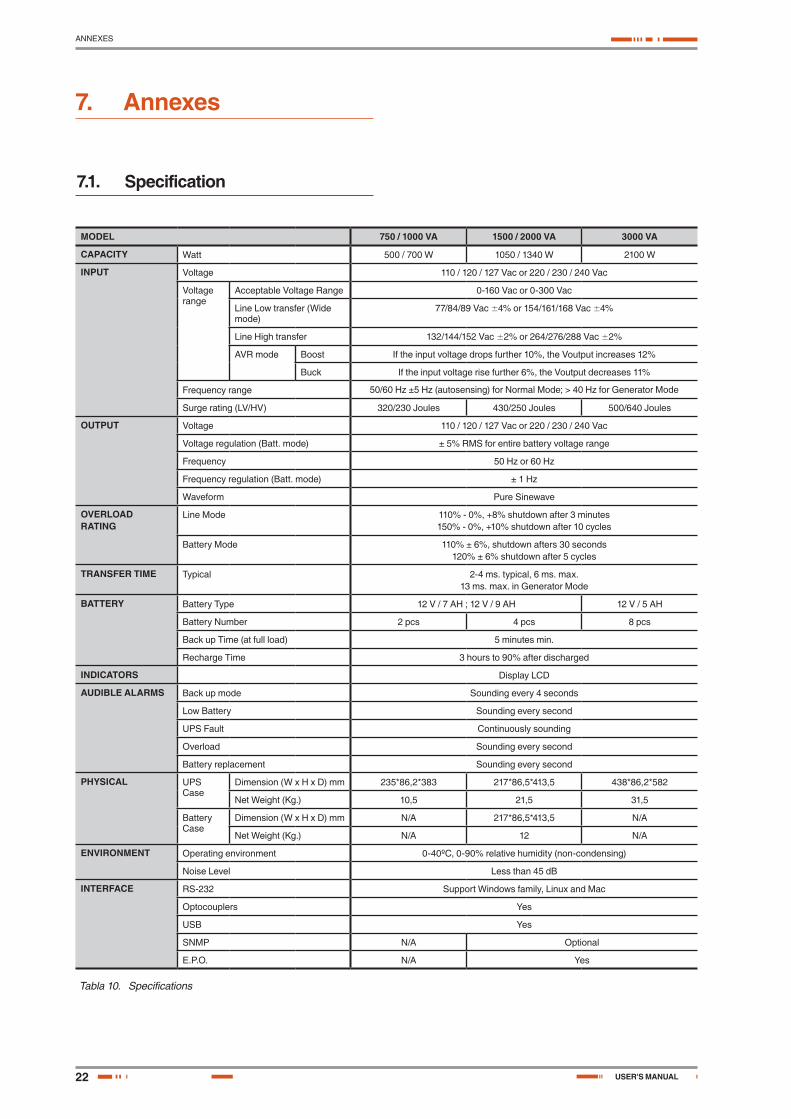
7. Annexes
7.1. Specification
MODEL 750 / 1000 VA 1500 / 2000 VA 3000 VA
CAPACITY Watt 500 / 700 W 1050 / 1340 W 2100 W
INPUT Voltage 110 / 120 / 127 Vac or 220 / 230 / 240 Vac
Voltage range
Acceptable Voltage Range 0-160 Vac or 0-300 Vac
Line Low transfer (Wide mode)
77/84/89 Vac ±4% or 154/161/168 Vac ±4%
Line High transfer 132/144/152 Vac ±2% or 264/276/288 Vac ±2%
AVR mode Boost If the input voltage drops further 10%, the Voutput increases 12%
Buck If the input voltage rise further 6%, the Voutput decreases 11%
Frequency range 50/60 Hz ±5 Hz (autosensing) for Normal Mode; > 40 Hz for Generator Mode
Surge rating (LV/HV) 320/230 Joules 430/250 Joules 500/640 Joules
OUTPUT Voltage 110 / 120 / 127 Vac or 220 / 230 / 240 Vac
Voltage regulation (Batt. mode) ± 5% RMS for entire battery voltage range
Frequency 50 Hz or 60 Hz
Frequency regulation (Batt. mode) ± 1 Hz
Waveform Pure Sinewave
OVERLOAD RATING
Line Mode 110% - 0%, +8% shutdown after 3 minutes150% - 0%, +10% shutdown after 10 cycles
Battery Mode 110% ± 6%, shutdown afters 30 seconds120% ± 6% shutdown after 5 cycles
TRANSFER TIME Typical 2-4 ms. typical, 6 ms. max.13 ms. max. in Generator Mode
BATTERY Battery Type 12 V / 7 AH ; 12 V / 9 AH 12 V / 5 AH
Battery Number 2 pcs 4 pcs 8 pcs
Back up Time (at full load) 5 minutes min.
Recharge Time 3 hours to 90% after discharged
INDICATORS Display LCD
AUDIBLE ALARMS Back up mode Sounding every 4 seconds
Low Battery Sounding every second
UPS Fault Continuously sounding
Overload Sounding every second
Battery replacement Sounding every second
PHYSICAL UPS Case
Dimension (W x H x D) mm 235*86,2*383 217*86,5*413,5 438*86,2*582
Net Weight (Kg.) 10,5 21,5 31,5
Battery Case
Dimension (W x H x D) mm N/A 217*86,5*413,5 N/A
Net Weight (Kg.) N/A 12 N/A
ENVIRONMENT Operating environment 0-40ºC, 0-90% relative humidity (non-condensing)
Noise Level Less than 45 dB
INTERFACE RS-232 Support Windows family, Linux and Mac
Optocouplers Yes
USB Yes
SNMP N/A Optional
E.P.O. N/A Yes
Tabla 10. Specifications
USER'S MANUAL


Avda. de la Serra, 10008460 PalautorderaBARCELONATel. +34 93 848 24 00
902 48 24 00Fax. +34 94 848 11 [email protected]. (S.T.S.) 902 48 24 01Fax. (S.T.S.) +34 848 22 [email protected]
MADRIDBARCELONABILBAOGIJÓNLA CORUÑALAS PALMAS DE G. CANARIAMÁLAGA
MURCIAPALMA DE MALLORCAPAMPLONASAN SEBASTIANSEVILLAVALENCIAVALLADOLIDZARAGOZA
BRANCHES AND SERVICES and TECHNICAL SUPPORT (S.T.S.....)
FRANCEPORTUGALHUNGARYUNITED KINGDOM
CHINASINGAPOREMEXICO
SUBSIDIARIES
GERMANYBELGIUMDENMARKHOLLANDIRELANDNORWAYPOLANDCZECH REPUBLICRUSSIASWEDENSWITZERLANDUKRAINEARGENTINABRAZILCHILECOLOMBIACUBAECUADOR
PERUURUGUAYVENEZUELASAUDI ARABIAALGERIAEGYPTJORDANKUWAITMOROCCOTUNISIAKAZAKHSTANPAKISTANUEAPHILIPPINESINDONESIAMALAYSIATHAILANDVIETNAM
REST of WORLD
Product Range
Uninterruptible Power Supply UPS
Lighting Flow Dimmer-Stabilizers
Power Supplies
Static Inverters
Photovoltaic Inverters
Microturbines
Voltage Stabilisers
Not
a: S
alic
ru c
an g
ive
othe
r ele
ctro
nics
sol
utio
ns a
ccor
ding
to th
e ap
plic
atio
n sp
ecifi
catio
ns o
r tec
hnic
al s
peci
ficat
ions
.
U N I N T E R R U P T I B L E P O W E R S U P P LY ( U P S ) + L I G H T I N G F L O W D I M M E R S TA B I L I Z E R S + P O W E R S U P P LY + S TAT I C I N V E R T E R S + P H O T O V O LTA I C I N V E R T E R S + M I C R O T U R B I N E S + V O LTA G E S TA B I L I S E R S
EK459C01


![Catalogo General Salicru SPA[1]](https://img.pdfslide.net/doc/110x75/557201124979599169a0b34e/catalogo-general-salicru-spa1.jpg)